
1
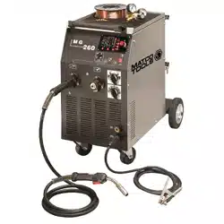
INSTRUCTION MANUAL FOR WIRE WELDING MACHINE
IMPORTANT: BEFORE STARTING THE EQUIPMENT, READ THE CONTENTS OF THIS
MANUAL. THIS EQUIPMENT MUST BE USED SOLELY FOR WELDING OPERATIONS AND
USED ONLY IN AN INDUSTRIAL OPERATING ENVIRONMENT.
1 SAFETY PRECAUTIONS
WELDING AND ARC CUTTING CAN BE HARMFUL TO YOURSELF AND OTHERS. The
user must therefore be educated against the hazards, summarized below, deriving from welding
operations. For more detailed information, order the manual.
ELECTRIC SHOCK - May be fatal.
Install and earth the welding machine according to the applicable regulations.
Do not touch live electrical parts or electrodes with bare skin, gloves or wet clothing.
Isolate yourselves from both the earth and the workpiece.
Make sure your working position is safe.
FUMES AND GASES - May be hazardous to your health.
Keep your head away from fumes.
Work in the presence of adequate ventilation, and use ventilators around the arc to prevent gases from
forming in the work area.
ARC RAYS - May injure the eyes and burn the skin.
Protect your eyes with welding masks fitted with filtered lenses, and protect your body with
appropriate safety garments.
Protect others by installing adequate shields or curtains.
RISK OF FIRE AND BURNS
Sparks (sprays) may cause fires and burn the skin; you should therefore make sure there are no
flammable materials in the area, and wear appropriate protective garments.
NOISE
This machine does not directly produce noise exceeding 80dB. The plasma cutting/welding procedure
may produce noise levels beyond said limit; users must therefore implement all precautions required
by law.
PACEMAKERS
The magnetic fields created by high currents may affect the operation of pacemakers. Wearers of vital
electronic equipment (pacemakers) should consult their physician before beginning any arc welding,
cutting, gouging or spot welding operations.
EXPLOSIONS
Do not weld in the vicinity of containers under pressure, or in the presence of explosive dust, gases or
fumes. All cylinders and pressure regulators should be handled with care.
ELECTROMAGNETIC COMPATIBILITY
This machine is manufactured in compliance with the instructions contained in the harmonized
standard.
IN CASE OF MALFUNCTIONS, REQUEST ASSISTANCE FROM QUALIFIED
PERSONNEL.
2
2 GENERAL TECHNICAL DESCRIPTION
2.1 SPECIFICATIONS
This manual has been prepared with the intent of instructing the operator on how to install, operate,
and properly maintain this electric arc welding machine. This machine is a constant voltage power
source for MIG and OPEN-ARC welding. Upon receiving and unpacking the machine, make a careful
inspection to ensure that there are no damaged parts. Should there be a claim for losses or damages it
must be made by the purchaser directly to the shipper who handled the goods. When requesting
information about this welding machine, please state the machine’s part number and serial number to
ensure receiving accurate information relating to your machine.
2.2 DESCRIPTION OF TECHNICAL SPECIFICATIONS
MODEL: The model of the machine
INTN’L STANDARDS: EN 60974-10:2003
SN: Machine Serial Number which must appear on requests or inquiries concerning the machine.
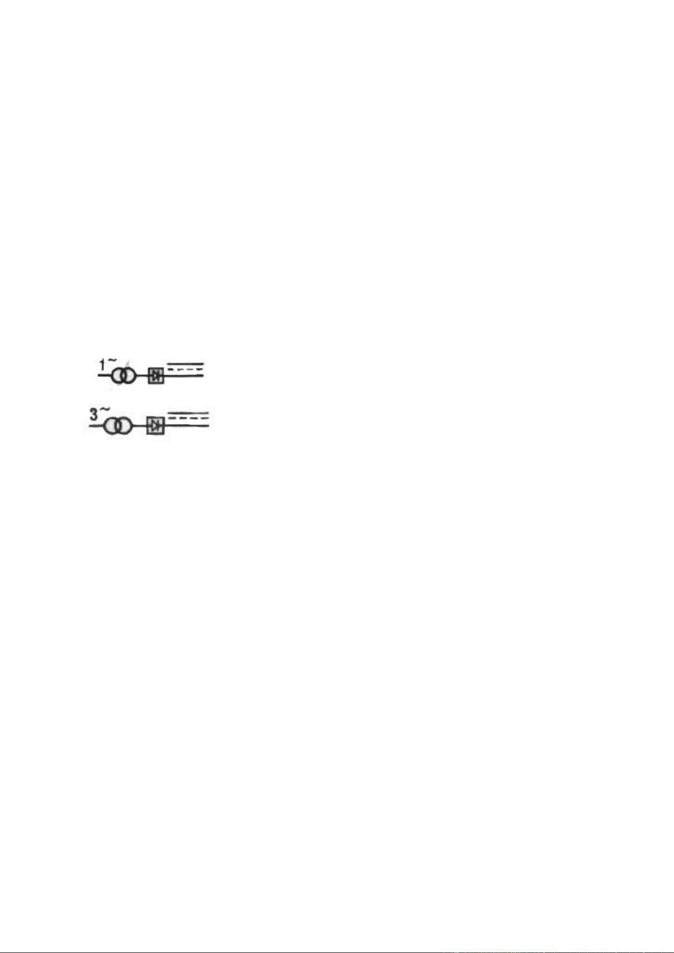
Single-phase transformer-rectifier
Three-phase transformer-rectifier
3-50/60Hz Three-phase input supply at 50 or 60 Hz
1-50/60Hz Single-phase input supply at 50 or 60 Hz.
Uo Secondary no-load voltage (peak value).
X Duty-Cycle Percentage
The duty-cycle is the number of minutes, expressed as a percentage, the machine can operate (arc on)
within a ten minute period without overheating. The duty cycle varies according to the output current.
I2 Output welding current
I1 Input Amps absorbed corresponding to different output levels (I2).
U2 Secondary voltage with welding current I2.
U1 Nominal supply voltage
IP21 Machine case protection class. The 1 in the second digit place means that this unit is not fit to work
outdoors in the rain.
F Insulation Class
NOTE: This machine has also been designed to work in class 3 pollution areas .
3 INSTALLATION
3.1 SETUP
Place the machine in a clean, well ventilated area. Dust, dirt, or any other foreign material that might
enter the machine may restrict the cooling (ventilation) which could affect the machine’s performance.
Fasten the (rotating support to the machine top and fix the handle) the wheels and the bottle support.

3
3.2 INPUT POWER CONNECTIONS
This machine must be installed by skilled personnel and wired in accordance with local codes.
When installing qualified plug make sure to connect Green (w/yellow stripe) wire to ground and other
two power leads to Line.
The machine must be connected to the input supply voltage marked on the input power cord.
This machine must never be used without the top and side covers. This is both for obvious safety
reasons and to avoid interference with the machine’s internal cooling system. The warranty is to be
considered null and void it this machine is used without the protection of its top and side covers.
3.3 OUTPUT CONNECTIONS
3.3.1 Wire feeder connection
This power source is compatible with external wire feeders. To connect the power source to the wire
feeder units use the extension cable.
3.3.2 Connecting the work return lead clamp.
Connect the male end of the work return lead to one of the impedance taps on the front panel of the
machine. The impedance tap designated by provides the maximum amount of impedance
and is recommended when welding thinner aluminum, stainless steel, and carbon steels of
binary or ternary composition. The impedance tap designated by provides the least
amount of impedance and is recommended when using carbon dioxide (Co2) as a shielding gas to
weld thicker carbon steels of binary or ternary composition.
It is generally advisable to use low impedance values for small diameter wires and high values for big
diameter wires.
After having selected the proper impedance tap, attach the work return clamp to the work to be
welded.
Make sure that the ground clamp is tightly fastened to the work return cable and periodically check
that this connection remains well tightened. A loose connection can cause weld current drops or
overheating of the work return lead and clamp which, in turn, creates the risk of burns from accidental
contact with the work return lead. The weld circuit must not be placed deliberately in direct or indirect
contact with the ground conductor if it is not on the work to be welded.
3.3.3 Connecting Cylinder Gas Hose.
Keep the cylinders in an upright position by chaining them to both upper and lower supports.
Do not lift the machine with the cylinder on its support shelf.
Keep the cylinder away from the welding area and un-insulated electric circuits.
Cylinders containing inert gas have to be equipped with a pressure regulator and a flow meter.
After having positioned the cylinder(s), connect the gas hose that comes out from the rear of machine
to the gas regulator output. NOTE: separate gas lines to mig gun and spool gun machine connects
Regulate the gas flow to 8-10 L/min (15-20 CFH).
4
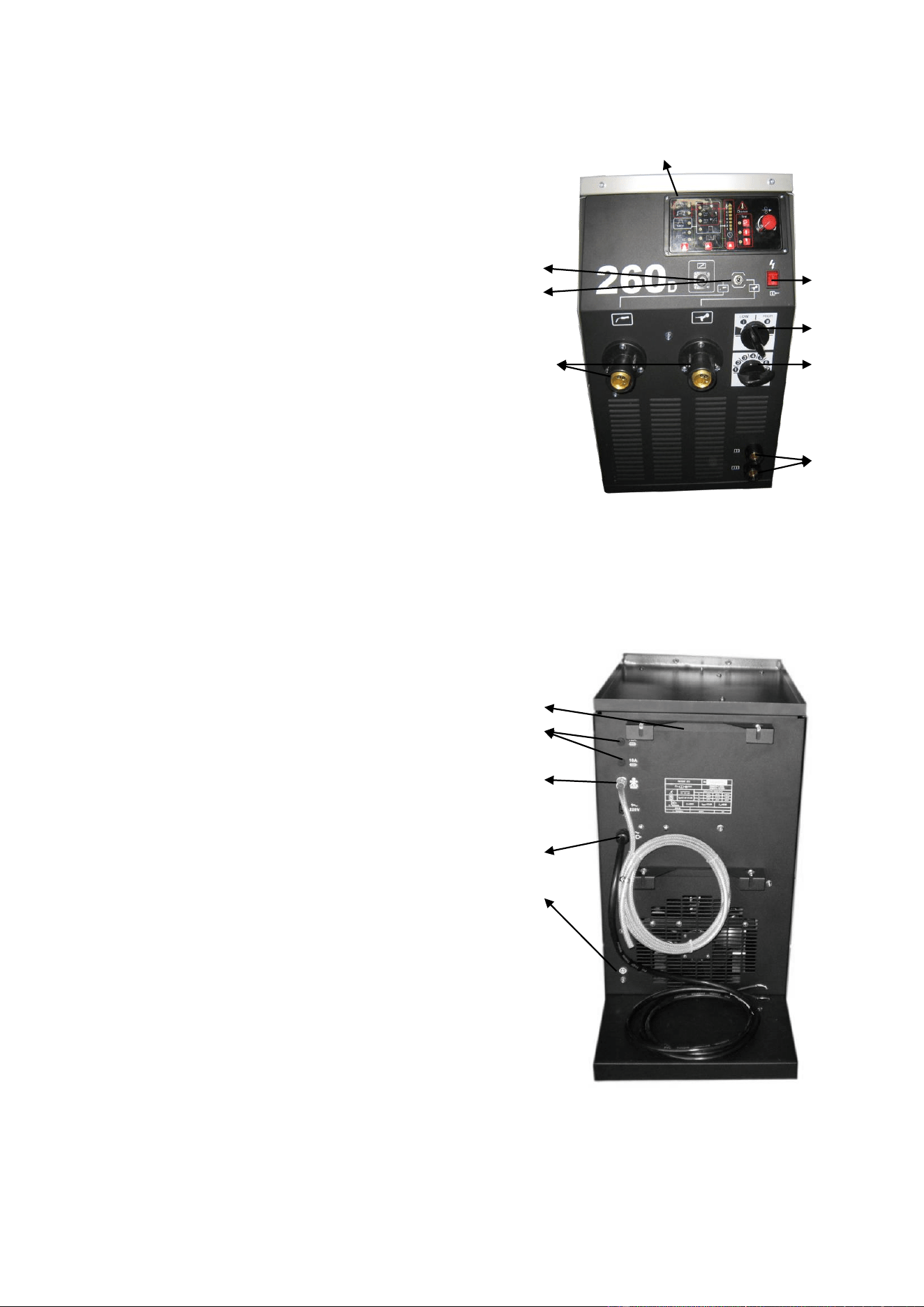
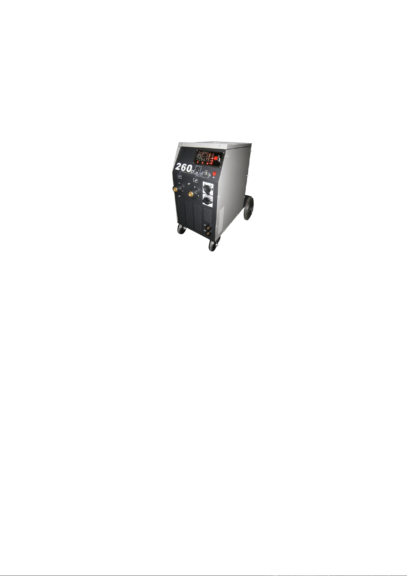
4 DESCRIPTION OF CONTROLS
4.1 CONTROLS ON GENERATOR FRONT PANEL
A: Digital control
B: Connector of torch
C: Power switch
D: Rotary weld voltage switch:
This switch adjusts the weld voltage range.
D2: Rotary weld voltage switch:
This switch allows the fine tuning of
the welding voltage selected with switch G.
(Step adjustment)
E: Quick connector for work return lead
F: control socket
G: toggle switch (torch selection)
4.2 CONTROLS ON GENERATOR REAR PANEL
A: Gas pipe connecter
B: Input power cable (Confirm the power voltage before
use)
D: Support for cylinder
E: Power fuses for control power and wire feed power
F: Ground connector
D
E
A
B
F
F
G
B
C
D
D2
E
A
5
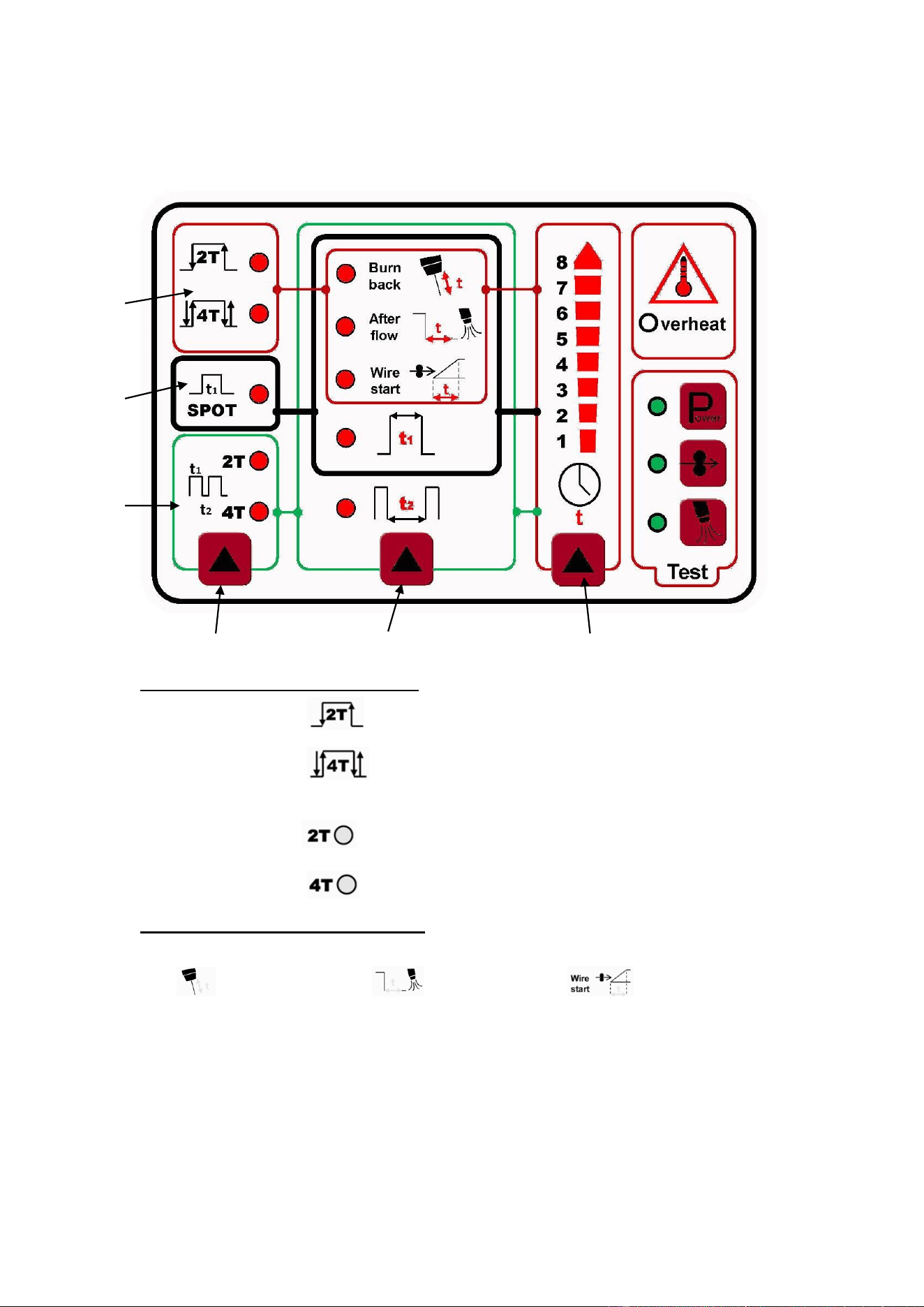
4.3 Digital Control description
1---Trigger Function Select Button: Three modes to select
A---MIG welding mode: ---MIG welding 2T mode (non-latching trigger)
---MIG welding 4Tmode (latching trigger)
B---Spot welding mode: Set time with “3” Select Button
C---Stitch welding mode: ---Stitch welding 2Tmode (non-latching trigger)
---Stitch welding 4Tmode (latching trigger)
2---Parameter Setting Select Button: Please note frame color on the panel:
A) MIG Welding modes (RED frame)
---burn back ---gas after flow ---wire start
t3 Timer: 1 (short) to 8 (long)
B) Spot welding modes ( frame)
t1---Welding time for “spot” or “stitch ON” operation.
C) Stitch welding modes (GREEN frame)
t2---Welding time for “stitch OFF” operation.
1 2 3
A
B
C

6
3--- Timer Setting Select Button:
The higher the number, the longer the time for function selected.
4---Set-Up & Diagnostics Indicators
---Overheat warning. Machine will auto-reset after cooling period and light will go off.
---Power test. Confirms machine is wired correctly to 230VAC line power supply.
---Fast wire feeding test. Confirms wire feed motor is functional and used for set-up.
---Gas test. Confirms shield gas solenoid valve system is functioning correctly.
5 WELDING
5.1 INSTALLATION AND START-UP
Machine installation must be done by licensed professional. All connections must correspond to the
rules in force and must respect local laws and codes concerning accidents.
Confirm that the wire diameter selected matches that indicated on the drive roll and mount spool.
Loosen drive roll “Pinch” arm and slide wire over rollers and into guide tube 1-2 inches.
Reconnect “Pinch” arm and set wire tension being careful not to detent softer wires.
Check that the gas line is connected but the cylinder valve closed.
Position the welding machine so as to allow free air circulation in both front and rear panels.
5.2 THE MACHINE IS READY TO WELD
Connect the earth clamp (ground) to the part to be welded as close to the weld area as possible.
Turn the machine power “ON”.
Remove the gas nozzle from the gun neck by rotating it clockwise.
Remove the contact tip from the tip holder making sure not to loosen the tip holder/nozzle seat.
Hold torch away from work and press the trigger to feed the wire from the machine to the torch.
WARNING: Keep torch away from operator (face) and work while waiting for wire to feed out.
Slide contact tip over wire, making sure that the hole diameter is the same as that the wire being used,
and screw tip firmly into torch neck. Loose tip can cause poor weld and permanently damage torch.
Reinstall gas nozzle and open the gas cylinder with flowmeter set at 8-10L/min. (15-20 CFH)
WARNING: Check that the gas selected is correct for the material to be welded.
5.3 WELDING CARBON STEELS.
To weld carbon steels the following things are necessary:
1) Shielding gas which is most commonly Argon and Carbon dioxide, in a ratio of 75-80 % Argon
and 25-20% Carbon dioxide. Some applications, however, may require a mix of three gases: Argon,
Carbon dioxide (CO2), and dioxide (O2). These gas mixtures generate heat during welding and as a
result the weld bead will be well filleted and neat in appearance. The penetration, however, will not be
deep.

7
The use of Carbon dioxide as the shield gas results in a narrow weld bead with deep penetration but
the ionization of the gas will have an influence on arc stability.
2) Welding (Filler) wire should be of the same quality and type as the steel to be welded. It is
recommended that high quality wires be used and that welding with rusted wires be avoided because
they can give rise to defects in the weld bead. Generally, the wire current range can be calculated in
the following manner:
Diameter Ø of welding wire x 100 = minimum Amperage.
Diameter Ø of welding wire x 200 = maximum Amperage
Example: 1.20 Ø wire = 120 Amps Min. and 240 Amps Max. These amperages are based on the use
of an Argon/CO2mixture as the shield gas and welding in the Short Arc transfer mode.
3) Avoid welding on rusted work pieces or work having spots of oil and grease present on the surface.
4) Welding torch must be rated for the welding currents (Amps) that are going to be used.
5) Periodically check that the two handles making up the ground clamp are not damaged and that the
welding cables (torch cable and the work return lead) do not have any cuts or burn marks that would
reduce their efficiency.
5.4 WELDING STAINLESS STEEL
Welding stainless steels in the 300 series (the austenitic series) must be done using a shield gas
mixture of predominantly Argon with a small percentage of O2 added to stabilize the arc. The
recommended mixture is AR/O2 in the ratio of 98/2. Do not use CO2 or AR/CO2 shield gases.
Stainless (Aluminum) must be very clean for good welds. Do not touch the welding wire with your
bare hands.
The wire must be of a higher quality than the work to be welded and the weld area must be clean.
5.5 WELDING ALUMINIUM
Requirements for aluminum welding:
1) 100% Argon as welding shield gas.
2) A torch wire of composition suitable for the basic material to be welded.
For ALUMAN welding wire 3.5% silicon.
For ANTICORODAL welding wire 3.5% silicon.
For PERALUMAN welding wire 5% magnesium.
For ERGAL welding wire 5% magnesium.
3) A torch prepared for aluminum welding with special Teflon liner and AL style contact tip or
Aluminum spool gun attached to machine.
4) Use drive rolls that are suitable for aluminum wire. The drive rolls, when being installed, must be
tightened as tight as possible.
5) Use contact tips that are suitable for aluminum wire and make sure that the diameter of the contact
tip hole corresponds to the wire diameter that is going to be used.
6) Use abrasive grinders and tool brushes specifically designed for aluminum. Never use these tools
on other materials. REMEMBER that cleanliness equals quality.
The wire spools must be stored in plastic bags with a dehumidifier.

8
6 COMMON ALUMINUM WELDING DEFECTS
A- DEFECT- Porosity (in, or on the surface of the weld bead)
CAUSES Bad wire (rust on the surface).
Insufficient gas shielding due to:
- Inadequate gas flow due to a block in the gas line.
- Defective flowmeter.
- Gas regulator covered with frost because CO2 heater regulator was not used.
- Failure of gas valve solenoid.
- Gas nozzle plugged up with spatter.
- Air drafts in the welding area.
B- DEFECT- Shrinkage Cracks
CAUSES Welding wire or work to be welded dirty or rusty.
Weld bead too small.
Weld bead too concave.
Too much weld bead penetration.
C- DEFECT- Lateral cracking
CAUSES Welding speed too fast.
Low current and high arc voltages.
D- DEFECT- Too much Spatter
CAUSES Voltage too high
Insufficient impedance
No gas heater used for CO2 shielding gas.
7 GENERAL MAINTENANCE
Torch Nozzle: Periodically clean the nozzle of all weld spatter that may have accumulated during
welding operations. If the nozzle should become distorted or oval in shape then it must be replaced.
Contact tip: A good contact between the contact tip and the wire ensures a stable arc and optimal
current output. Therefore, following steps must be followed:
A) The contact tip hole must be kept free of dirt or oxidation.
B) After lengthy welds, spatter can easily accumulate on the contact tip and prevent the wire
from being fed. The contact tip must be cleaned regularly and if necessary it must be replaced.
C) The contact tip must always be screwed tightly on to the body of the torch. The thermal
cycles which the torch undergoes during operation may loosen the contact tip which, in turn, may
cause the torch body and nozzle to overheat or cause unsteady wire feed.
Torch Liner: Check for deposits of copper dust or tiny metal shavings in the lining. Periodically
clean the liner with dry compressed air. Wire liners are exposed to continual wear and therefore they
must be replaced after a certain period of time.
Wire Feed Drive: Periodically clean the wire feed assembly and the drive rolls from any rust or metal
shavings due to the feeding of the wire. A periodic check of all the components of the wire feed
assembly, spool holder, drive rolls, wire liner and the contact tip is recommended.

9
8 TROUBLESHOOTING
TROUBLE
PROBABLE CAUSE
REMEDY
Limited electric
output
Wrong input voltage or a phase missing
Check the voltage on all phases of the feed line
and/or the remove control switch contacts
A line fuse is blown
Replace it
Wrong connection on the voltage
changer terminal board
Check the terminal board connections by
following the plate scheme
The rectifier diode are blown
Replace the rectifier
Loosened torch or ground connections
Tighten all connections
Welding regulation contactor has an
burnt contacts
Replace the contactor
Loose transformer wire on contactor
Remove wire under terminal, inspect for good
connection and reinstall on contactor.
Welding with a
lot of metal
spatter
Wrong adjustment of the welding
parameters
Select the correct parameters through the
welding voltage switch and the wire-speed
adjustment potentiometer
Wire advancing unproperly
Uncorrected sheath diam.
Insufficient grounding
Check grounding connections
Wire not
advancing
Wire roller with too wide groove
Replace roller
Wire advancing
unproperly
Obstructed or clogged liner
Extract it and clean
Loose wire pressing roller.
Tighten it
Coil reel friction too tight
Loosen and adjust it
Current nozzle clogged
Replace it
The wire jams
or entangles
between the
drive rolls and
the torch feed
wire guide
Wrong contact tip diameter
Replace it
Wrong drive roller groove or alignment
Flip, replace or re-align roller
Obstructed torch cable connection or
clogged/kinked wire conduit liner.
Remove and clean obstruction, tighten torch
cable and clean or replace wire liner.
Note: All repair work must be done by qualified personnel.
Disconnect the power input cable from the mains supply before replacing cables or before removing
the unit covers. The machine is equipped with a thermostat that shuts the machine down when the
power source overheats. After the thermostat intervenes, let the power source cool down for several
minutes before resuming welding operations.
The troubleshooting table lists troubles, causes and remedies for those troubles that occur most
commonly.
9 WELDING MACHINE SERVICING
Machine should be serviced by trained welding professional only…please contact your dealer
for repair locations or the manufacturer’s technical service department at 847-662-8763 or
800-554-0074.
10
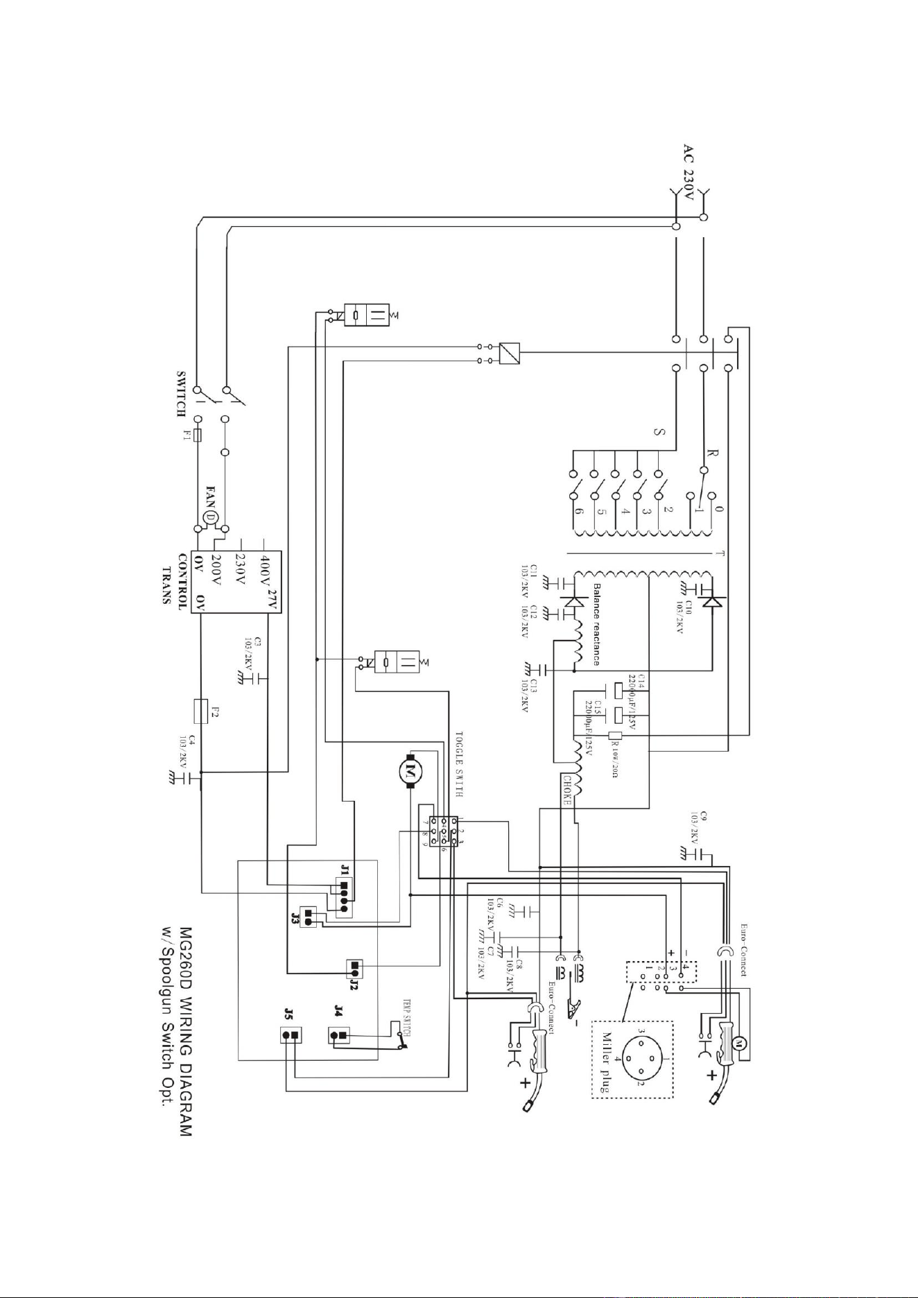
10 ILLUSTRATION OF WORKING PRINCIPLE
11
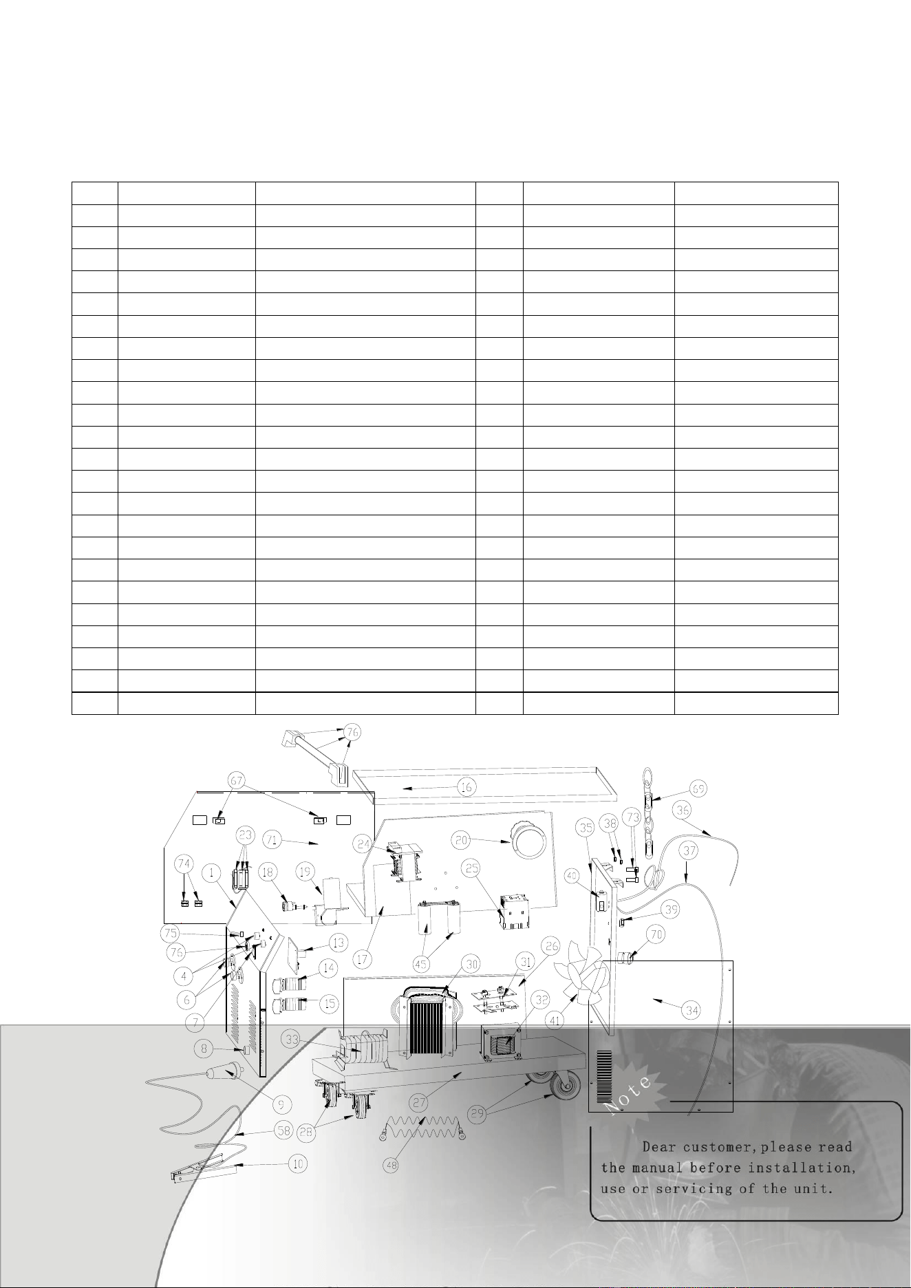
11 ILLUSTRATION OF EXPLODED
PARTS & SERVICE HOTLINE 847-662-8763 / 800-554-0074
CODE: MG260D
No.
Code No.
Description
No.
Code No.
Description
1
EW064004-12-1
front panel
30
526.0025
main transformer
4
530.0011
wire speed knob
31
526.0016
rectifier
6
511N9997
torch connector plastic case
32
WA055000-2E
Inductance choke
7
530.0020
power switch
33
WB063000-E
balance reactance
8
511N0014
ground socket
34
EW063004-19-3
Big side panel (right)
9
511N0015
ground plug
35
EW063004-12-6-A
back panel
10
513N0003
earth clamp
36
100N9000
power cord
13
526.0029
digital control PCB
37
526.0026
gas pipe
14
526.0021
2 steps switch
38
GMC-1
power fuse 1A
15
526.0022
7 steps switch
GMC-5
power fuse 5A
16
EW063004-19-1
top tray
40
709.0116
gas solenoid
17
EW063004-12-3
inside baffle
41
526.0015
fan
18
501N9994
torch connector
45
CA055003
capacitor
19
526.0010
wire feeder
48
EK055010
stainless wire
20
526.0013
wire feeder reel
58
199.0025
work return lead
23
RD062009-E
resistor
67
530.0017
closing
24
526.0017
control transformer
69
EE055000
chain
25
526.0014
magnetic switch
70
SE055004
gland
26
EW063004-19-2
Small side panel (left)
71
EW063004-19-4
door panel
27
EW063004-12-4
bottom board
73
525.0025
20mm fuse-holder
28
526.0019
front swivel caster
74
530.0019
Hinge
29
526.0020
2-wheels & axel set
75
526.0011
toggle switch
76
526.0018
Machine handle
12
MG 260D