
OPERATION MANUAL
MU-C HUS
EX MACHINE No 2015
EDITION 11-2022
REFERENCE NUMBER MU-C-F-HUS_BA_15_EN_2022-11
EN |
Original

Machine identification
In order for your dealer to assist you as efficiently as possible, you will need to provide some information
about your machine. Please enter the information here.
Designation
Working width
Weight
Machine number
Additional equipment
Dealer's address
Manufacturer's address
The copyright and usage rights are owned by Müthing GmbH & Co. KG Soest. Reproduction, transfer to other media, translation or the use of
extracts or parts of this manual without the explicit permission of Müthing GmbH & Co. KG Soest , is not permitted. All rights reserved. The contents
of this operating manual are subject to change without notice. The right to technical revision is reserved.
Müthing GmbH & Co. KG Soest
Am Silberg 23
59494 Soest
Germany

3
Handover declaration
Handover declaration
– Fill out this sheet with your dealer.
– Then separate this sheet from the operating manual and send it to the manufacturer within 10 days of delivery.
Only in this way will the guarantee be effective from the date of delivery
.
I have bought the machine described below from Müthing GmbH & Co. KG Soest, and confirm full
delivery and handover of the machine including the operating manual and spare parts list, as well
as training in operating the devices with safety instructions and warning information from your
dealer.
I confirm additionally that I have read and understood the operating manual and am in agreement with the
information contained therein.
This applies in particular to the chapter Safety.
Client
Machine
Name
First name
Address
Post code Town/city
Telephone Fax
E-mail Date
Machine
MU- Serial number
Working width Gear-box
Rigid mount-
ing
Non-rigid
mounting
Year of con-
struction
Delivery date
Delivered by
Signature of client Signature and stamp of sales partner
To
Müthing Gmbh & Co. KG Soest
Am Silberg 23
59494 Soest
Germany

4
Handover declaration

5
Handover declaration – Copy
Handover declaration – Copy
– This sheet remains with the client in the operating manual
I have bought the machine described below from Müthing GmbH & Co. KG Soest, and confirm full
delivery and handover of the machine including the operating manual and spare parts list, as well
as training in operating the devices with safety instructions and warning information from your
dealer.
I confirm additionally that I have read and understood the operating manual and am in agreement with the
information contained therein.
This applies in particular to the chapter Safety.
Client
Machine
Name
First name
Address
Post code Town/city
Telephone Fax
E-mail Date
Machine
MU- Serial number
Working width Gear-box
Rigid mount-
ing
Non-rigid
mounting
Year of con-
struction
Delivery date
Delivered by
Signature of client Signature and stamp of sales partner

6
Handover declaration – Copy

7
Table of Contents
Table of Contents
Handover declaration ................................ 3
Handover declaration – Copy ................... 5
About this operating manual .................... 8
Target group 8
Safety 8
Training 8
Other applicable documents 8
Symbols 9
Safety .......................................................... 10
For your safety 10
Warning signs 10
Definitions 13
Who is allowed to operate the machine? 13
Coupling 14
Centre of gravity 15
Road transport 17
Putting the machine into operation 17
Uncoupling the machine 19
Care and maintenance 19
Further regulations 20
Familiarising yourself with the machine . 21
Range of application of the machine 21
Features of the machine 22
Designation of components 23
Technical specifications 24
Delivery and assembly .............................. 26
Checking the scope of delivery 26
Coupling the machine ............................... 27
Adapter 27
Implement triangles 28
Mechanical drive 29
Preparation ................................................. 30
Working depth 30
Driving on the road .................................... 31
Transport position 31
Transport without coupling 31
Mulching ..................................................... 32
Task 32
Cleaning and care ...................................... 35
Cleaning 35
Care 35
Parking and storage .................................. 36
Setting down the machine in a secure position
36
Storing the machine 37
Maintenance ............................................... 38
For your safety 38
General information 39
Maintenance intervals and setting work 42
Lubricating work 43
PTO shaft 45
Gearbox oil 46
Tools 48
V-belt 49
Runners 52
Additional equipment ................................ 53
Wear insert 53
Counter cutter 53
Support wheels 53
Operating hours counter 53
Fault elimination ........................................ 54
Disposal of the machine ........................... 56
EC Declaration of Conformity .................. 57
EC Directive
2006/42/EG 57
UK Declaration of Conformity .................. 58
UKCA 58
Index ........................................................... 59

MU-C HUS
8
About this operating manual
About this operating manual
Target group
This operating manual is intended for trained machine operators and
persons who are otherwise qualified to carry out landscape work and
who have received training in how to use this machine.
Safety
Familiarise yourself with the contents of this operating manual which are
relevant for your activity before commissioning or assembling the ma-
chine. Always read through the safety instructions in the chapter “Safe-
ty” and observe the warning information in the individual chapters. In
this way, you will achieve optimum work results and operational safety.
For the employer:
Staff must be instructed in the safe handling of the machine before the
initial commissioning. Untrained or unauthorised persons are not per-
mitted to use the machine.
The following are included in this training:
• Checking that staff possess the necessary requirements for safely
handling the machine.
• Handing out the operating manual and the other relevant and appli-
cable documents or an intensive course of training which, in
particular, includes the safe handling of the machine.
Regular instruction ses-
sions
Instruct your staff regularly, but at least once a year, concerning the
basic procedural measures for safely handling the machine.
Training
You will receive training from your dealership concerning using the con-
trols, safe operation and care of the machine. Commissioning without
first receiving training is not permitted.
Other applicable
documents
In addition to the operating manual, other documents also form an inte-
gral part of the machine:
EC Declaration of Conformity Integral part of this opera-
ting manual
Chapter »EC Declara-
tion of Conformity«,
page 57
Spare parts list Integral part of the delivery
with this machine
PTO shaft operating manual Integral part of the delivery
with this machine

MU-C HUS
9
About this operating manual
Symbols
In order to make this manual clear and easy to read, we have used va-
rious symbols. They are explained below:
• A bullet point accompanies each item in a list
A triangle indicates operating functions which must be performed
An arrow indicates a cross-reference to other sections of this manual
[+] A plus sign indicates an accessory that is not included in the stan-
dard version.
Pictograms
We have also used pictograms to help you find instructions more qui-
ckly:
This symbol indicates information, tips and instructions about operation.
This symbol indicates tips for assembly or adjustment work.
This symbol indicates examples that help you to understand the instruc-
tions better.
Parts in the text which refer to individual machines or to conditions have
a colored background. After the colored section, the text then applies
again to all machines. For example:
Only for MU-Farmer/S with pneumatic brake system
Connect hydraulic hoses
The warning triangle indicates warning information. Failure to ob-
serve these safety instructions can result in:
• Moderate to serious injury
• Fatal injury
You will find the warning information associated with individual ope-
rations, where it is important to observe the warning information be-
fore these operations are carried out.
You will also find safety instructions in the chapter »Safety« which
cannot be assigned to any particular operations, but increase your
ability to work safely in different situations.
This sign indicates important instructions regarding the machine.
Failure to observe these safety instructions can result in:
• Serious faults in the correct operation of the machine.
• Damage to the machine.
Connect brake hoses
MU-C HUS
10
Safety
Safety
For your safety
This chapter contains general safety instructions. Each chapter of the
operating manual contains additional warning instructions which are not
described here. Observe the safety instructions:
• in the interest of your own safety,
• in the interest of the safety of others
• to ensure the safety of the machine
Numerous risks can result from handling landscaping machines the
wrong way. Therefore, always work with particular care and never under
time pressure. Therefore, always work with particular care and never
under time pressure.
For the employer:
Inform personnel working with the machine of these safety instructions
at regular intervals and according to statutory regulations.
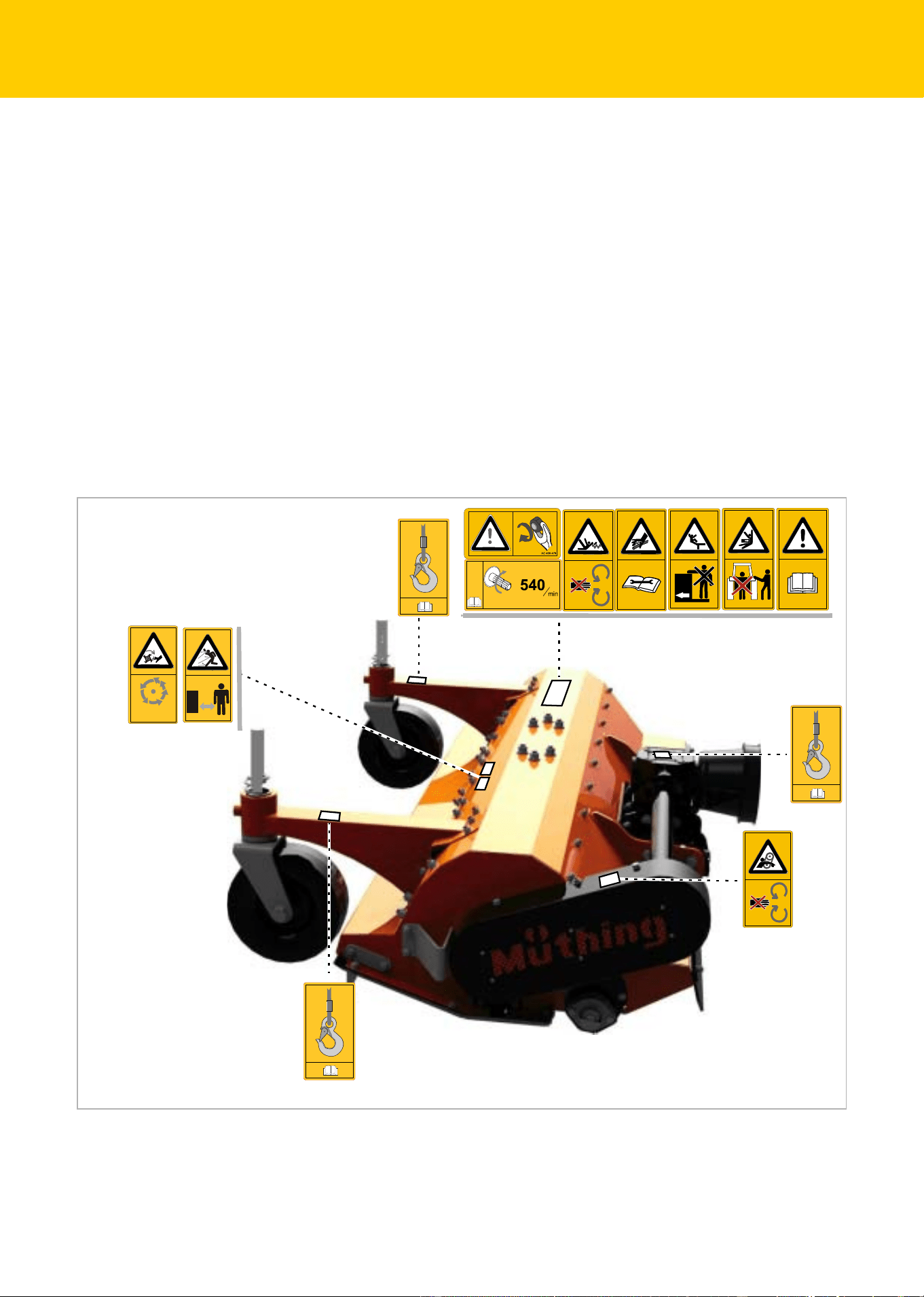
Warning signs
On the machine you will find labels that serve to ensure your safety. The
labels must not be removed. If labels become illegible or begin to peel
off, new labels can be ordered and attached in the appropriate places.
STOP
AC 495465
AC 351057
AC 351057
AC 351057
MU-C HUS
11
Safety
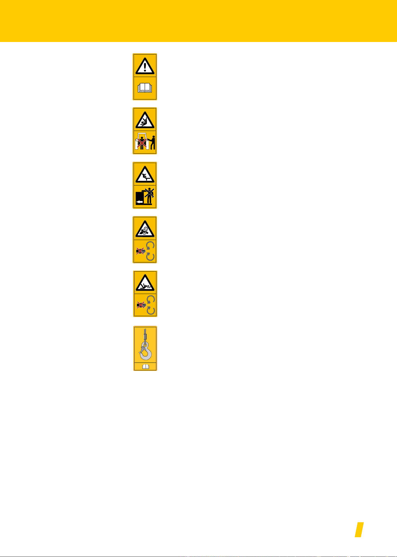
Meaning of warning
signs
Read the operating manual carefully and follow the instructions
Commissioning of the machine must not take place before the operating
manual has been read and understood. This particularly applies to sa-
fety instructions.
Do not stand between the carrier vehicle and the machine
Standing between the carrier vehicle and the machine while the engine
is running is prohibited, especially during coupling and uncoupling. The
carrier vehicle must also be secured so that it cannot roll away.
Riding on the machine is prohibited
It can result in serious or even fatal injury.
Do not remove protective devices
Do not open or remove the protective devices while the engine of the
carrier vehicle is running. Never operate the machine without the pro-
tective device.
Be aware of the danger of being pulled in
There is a danger of being pulled into the PTO shaft in the event of in-
appropriate use.
Shackles
Only raise the machine using loading equipment at the points indicated.
AC 351057
MU-C HUS
12
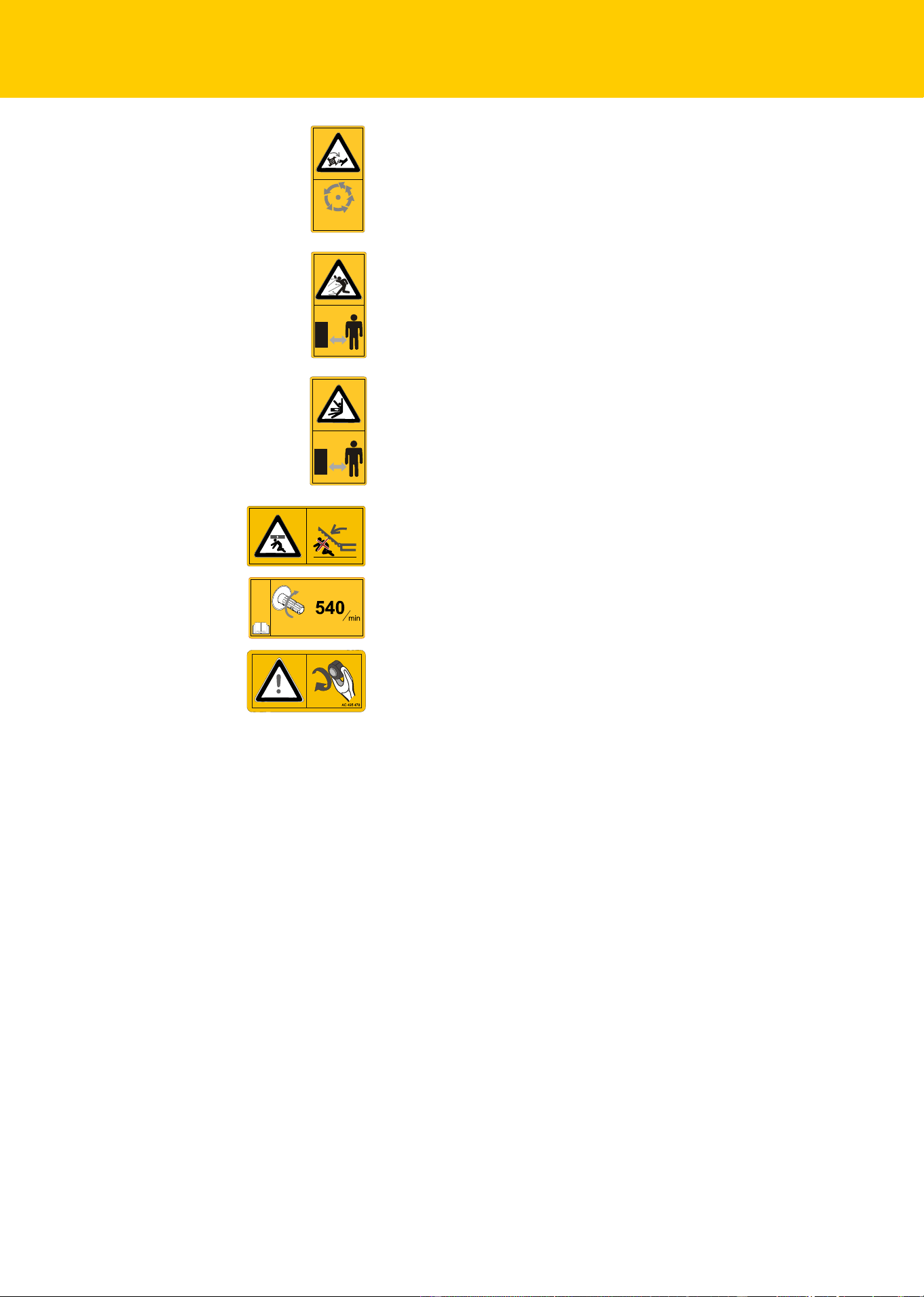
Safety
Rotating and trailing machine parts
Only approach the machine when all machine parts have stopped mo-
ving.
Danger of objects being thrown out
During operation, there is a danger of objects such as stones being pi-
cked up and thrown out by the machine. Ensure that no persons are
present in the hazard area.
Danger from moving machine parts
Nobody is permitted to remain within the hazard area during operation.
Do not stand in the slewing range
There is an extreme risk of injury within the slewing range from slewing
or folding machine parts.
Check the rotational speed of the PTO stub shaft
Connect PTO shaft to a PTO stub shaft with an appropriate rpm. Always
switch off the PTO stub shaft when working on the machine.
Retighten screws
After the first hours of operation, and as required, all screws must be
checked and tightened if necessary. Vibrations might have loosened the
screwed connections.
STOP
AC 495465

MU-C HUS
13
Safety
Definitions
All direction information is given in relation to the direction of travel of
the machine:
Who is allowed to
operate the ma-
chine?
Only qualified personnel
Only qualified persons who have been informed of the dangers associ-
ated with handling the machine are permitted to operate, service or re-
pair the machine. As a rule, such persons are trained machine opera-
tors or have had similar intensive training.
Up
Right
Down
Left
Front
Rear

MU-C HUS
14
Safety
Coupling
Increased risk of injury
There is an increased risk of injury when the machine is being coupled
to the carrier vehicle. Therefore:
• The carrier vehicle must be fitted with the corresponding adaptor in
order to be coupled to the machine.
• Only couple the machine with the road chassis raised
• Secure the carrier vehicle so that it cannot roll away.
• Never stand between the carrier vehicle and the machine during
coupling.
• Actuate the power lever slowly and carefully.
Failure to observe these instructions can result in serious or fatal injury.
Connect electric wires or cables only after mounting the attach-
ment
The electrical supply to the carrier vehicle must not be connected up du-
ring the fitting of the lighting equipment. Short circuits and damage to
the electronics are possible.
Only connect hydraulics at zero pressure
Only connect the hydraulic hoses to the carrier vehicle while the hydrau-
lic system on the carrier vehicle and machine is de-pressurised. A hy-
draulic system under pressure can trigger unpredictable machine mo-
vements.
High pressures in the hydraulic system
The hydraulic system is under high pressure. Regularly check all lines,
tubes and screwed connections for leaks and externally visible damage.
Only use suitable tools when looking for leaks. Rectify any damage im-
mediately. Oil escaping under pressure may result in injuries and fires.
In the event of injuries, seek medical attention immediately.
Color-coded hydraulic hoses
To avoid operating errors, the sockets and plugs of the hydraulic con-
nections between the carrier vehicle and the machine should be color-
coded. Wrongly connected hydraulic hoses can trigger unpredictable
movements of the machine.
MU-C HUS
15
Safety
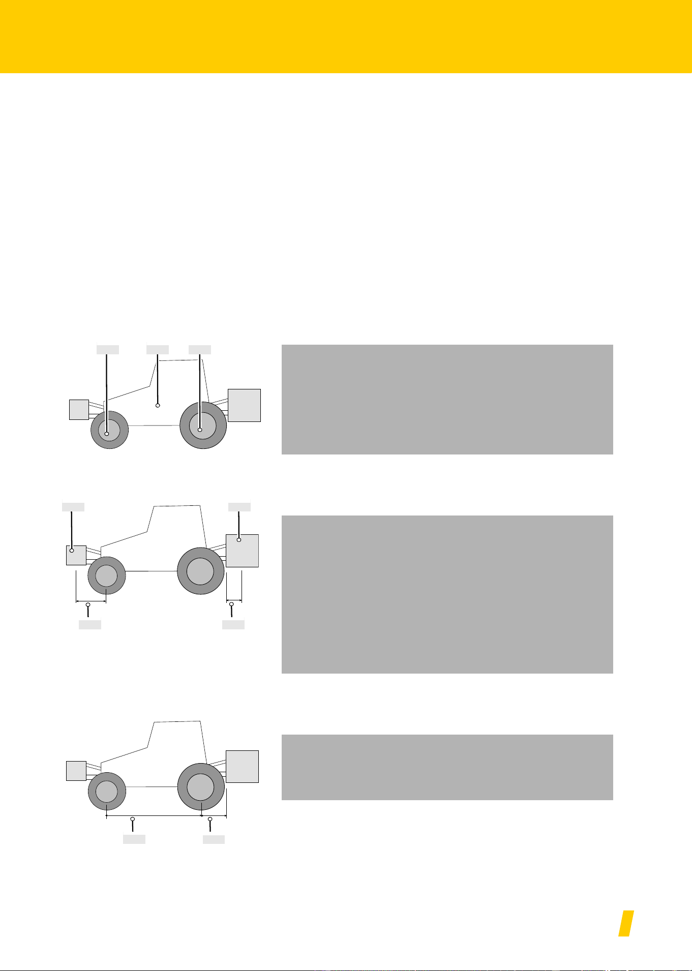
Centre of gravity
Observe the total weight, axle loads, tyre load-bearing capacity
and minimum ballast specifications
The front/rear attachment of machines must not cause the carrier vehic-
le's permissible total weight, permissible axle loads, or tyre load-bearing
capacity to be exceeded. The front axle must bear at least 20 % of the
empty weight of the carrier vehicle to ensure steering capability.
By investing some effort in making the calculations it is possible to de-
termine the:
• Total weight
• Axle loads
• Tyre load-bearing capacity and
• Minimum ballast
For this calculation, the following data is required:
Data from the operating manual of the carrier vehicle:
Data from this operating manual:
Data which you can determine by measuring:
• (A) unladen weight
• (B) front axle load
• (C) rear axle load
Please take into consideration, for example, the weight of water in
the tyres, accessories, etc.
• (D) total weight of the machine when rear-mounted; the suppor-
ting load with the machines attached
• (E) total weight of the machine when front-mounted
• (F) distance between the machine's centre of gravity when front-
mounted and the front-axle midpoint
• (G) distance between the lower link ball midpoint and the machi-
ne's centre of gravity when rear-mounted. With machines
attached, G=0.
• (H) wheel base of carrier vehicle
• (I) distance between the rear axle midpoint and the lower link
ball midpoint
Front axle
load
Empty
weight
Total weight front
attachment
Total weight rear
attachment
Distance:
Between front
attachment centre
of gravity and front
axle midpoint
Distance:
Between lower link
ball midpoint and
rear attachment
centre of gravity
Wheel
base
Rear axle
load
Distance:
Rear axle midpoint to
lower link ball midpoint
(B) (A) (C)
(E) (D)
(F) (G)
(I)
(H)

MU-C HUS
16
Safety
Calculation
The measured values can now be inserted into the formulas.
Ballast with front weights
Calculating the ballast with front weights
on rear-mounted machines.
Front ballast in kg =
Ballast with rear weights
Calculating the ballast with rear weights
on front-mounted machines.
Rear ballast in kg =
Front axle load
Calculating the actual front axle load
Front ballast in kg =
Total weight
Calculating the actual total weight
Total weight =
Rear axle load
Calculating the actual rear axle load
Rear axle load in kg = actual total weight - actual front axle load
Tyre load-bearing capacity
Data on the tyre load-bearing capacity of the front and rear wheels can
be found in the tyre manufacturer's documentation.
• The front tyre load-bearing capacity for two wheels is equal to twice
the permissible tyre load-bearing capacity of a single front wheel.
• The rear tyre load-bearing capacity for two wheels is equal to twice
the permissible tyre load-bearing capacity of a single rear wheel.
Summary
Check if the following conditions are met:
• The actual values for the rear axle load must be less than the per-
missible values stated in the operating manual of the carrier vehicle.
• The tyre load-bearing capacity must be greater than the values for
the rear axle load given in the operating manual.
• The actual total weight must be less than the permissible total weight
stated in the operating manual of the carrier vehicle.
If these conditions are not met, you are not allowed to couple the ma-
chine to this carrier vehicle.
If you have a sufficiently large weigh-bridge, you can determine the total
weight and the rear axle load by weighing.
DIG+ BH 02 A H,+–
FH+
-------------------------------------------------------------------------------------------
EFC H 045 A H,+–
HIG++
-------------------------------------------------------------------------------------
EFH BH DIG+–++
H
---------------------------------------------------------------------------------------
EAD++

MU-C HUS
17
Safety
Road transport
Make sure that the condition of the machine conforms to traffic re-
gulations
The machine must conform to current traffic regulations if you intend to
drive it on public roads. This includes for example:
• Lighting, warning and protective equipment must be fitted
• The permissible transport width and weight, axle load, tyre load-be-
aring capacity and total weight are observed
The driver and owner of the vehicle are liable if traffic regulations are not
observed.
Closing ball valves
If ball valves are provided on the hydraulic lines or the chassis cylinders,
the ball valves must be closed for road transport. The accidental actua-
tion of control devices on the carrier vehicle could otherwise cause mo-
vements on the machine. Accidents or damage to the machine may be
caused as a result.
Check release cable for the quick-release coupling
Release cables must hang loose and must not, when in their lowered
position, release the couplings of their own accord. Attached machines
might otherwise come loose from the three-point linkage of their own ac-
cord.
Riding on the machine is strictly prohibited
People or objects must never be transported on the machine. Riding on
the machine poses a risk to life and limb and is strictly prohibited.
Take the change in driving and braking performance into account
Driving and braking performance is altered when the machine is atta-
ched to the tractor. Take the width and balancing weight of the machine
into consideration, especially when cornering. A driving style which not
adjusted to the road conditions can lead to accidents.
Drive at a suitable speed
Always adjust your driving speed to the road conditions. Driving at ex-
cessive speeds in poor road conditions can create extremely high for-
ces which can severely load or overload the carrier vehicle and machi-
ne. Driving at unsuitable speeds can cause machine damage and lead
to accidents.
Putting the ma-
chine into opera-
tion
Training required before commissioning
The machine must not be put into operation until the user has been gi-
ven proper training by an employee of the dealer, a factory representa-
tive, or an employee of the manufacturer. Commissioning without trai-
ning can lead to damage to the machine due to false operation or acci-
dents can happen.
Ensure that the machine is in perfect working condition
Do not operate the machine unless it is in perfect working condition.
Check all important components and replace any defective components
before starting the machine. Defective components can cause damage
to equipment and personal injury.

MU-C HUS
18
Safety
Do not remove the protective equipment
The protective equipment must not be removed or by-passed. Check all
protective equipment before starting the machine. Unprotected machi-
ne parts can cause serious or fatal injury.
Riding on the machine is strictly prohibited
People or objects must never be transported on the machine. Riding on
the machine poses a risk to life and limb and is strictly prohibited.
Height of the machine and overhead power lines
If a height of 4.00 m is exceeded when folding the machine in and out,
the machine must not be folded in the vicinity of live overhead power li-
nes. Danger of electrocution! Should the machine come into contact
with a live overhead power line:
• Do not leave the carrier vehicle.
• Do not touch any of the metal parts on the carrier vehicle.
• Do not create any conductive contact with the ground
• Warn anyone in the area not to approach the carrier vehicle or
machine.
• Wait for help from professional emergency service personnel as po-
wer in the live overhead power line must first be switched off
Never climb onto the machine beneath live overhead power lines. The
voltage can jump across even if the lines are not actually touching the
machine.
Check the hazard area
Before driving off, folding out, and operating the machine and during
operation, check its hazard area. Make sure that you have an adequate
view. Do not begin work until the hazard area is cleared of any persons
or objects. Information regarding the hazard area can be found in the
corresponding chapter.
Chapter »Mulching«, section »Task«, Page 32.
Parts could be ejected from the machine at high speed in certain cir-
cumstances. The hazard area, particularly in front of and behind the ma-
chine, must be cleared of any persons, animals or objects before start-
ing.
Any use of the machine without verification of the hazard area can lead
to serious or fatal accidents.
Retighten all nuts, bolts and screws
Nuts, bolts and screws should be checked at regular intervals and tight-
ened if necessary. Screws can come loose unnoticed while operating.
Damage to the machine or accidents may be caused as a result.
What to do in the event of a fault
In the event of a malfunction, shut down and secure the machine imme-
diately. The fault may be eliminated immediately, or a specialist work-
shop must be assigned the task. Further operation of the machine can
lead to damage to the machine or injury to persons.

MU-C HUS
19
Safety
Uncoupling the
machine
Increased risk of injury
There is an increased risk of injury when uncoupling the machine from
the carrier vehicle. Therefore:
• Secure the carrier vehicle so that it cannot roll away.
• Never stand between the carrier vehicle and the machine during
uncoupling.
• Actuate the power lever slowly and carefully.
• Make sure the machine is standing on a secure and level surface
• Do not disconnect the hydraulic hoses until the hydraulic system of
the carrier vehicle and machine is de-pressurised.
Failure to observe these instructions can result in serious or fatal injury.
Care and mainte-
nance
Observe the care and maintenance intervals
Observe prescribed intervals for maintenance checks and inspections
specified in the operating manual. If these periods are not observed, this
can lead to damage to the machine, poor quality of work or accidents.
Use original replacement parts
Many components have special properties that are essential for the sta-
bility and correct operation of the machine. Unsuitable spare parts or ac-
cessory parts or incorrectly performed repairs or changes can cause da-
mage to the machine, accidents or serious injury.
Müthing strongly recommends using only approved original Müthing ac-
cessories and spare parts. Müthing can guarantee the safety, reliability
and suitability of these parts only.
Use of non-original Müthing spare parts shall invalidate any warranty
claims.
When performing care and maintenance work:
• Switch off the PTO stub shaft
• Depressurise the hydraulic system
• If possible, uncouple the carrier vehicle.
• Make sure the machine is standing securely. Provide additional sup-
port as required
• Do not use parts of the machine as climbing aids; use only secure
steps, ladders or other means of access
• Secure the machine against rolling away
• Never reach into the V-belt while it is running
It is only possible to guarantee work safety during care or maintenance
work through observing these regulations.
Turn off the electrical supply
Prior to carrying out work on the electrical system, disconnect the sys-
tem from the power supply. Systems supplied with electrical power can
cause damage to equipment and personal injury.

MU-C HUS
20
Safety
Replace hydraulic hoses
Replace hydraulic hoses every six years. Hydraulic hoses can age wit-
hout any externally visible damage. Defect hydraulic lines can lead to
severe or fatal injuries.
Caution when cleaning with a high-pressure cleaner
The machine can be cleaned using either water or a steam jet. Only use
a low pressure to clean bearings, fans, signal mixer units, plastic parts
and hydraulic hoses. Excessively high pressures can cause damage to
these parts.
Before carrying out welding work, disconnect the battery and al-
ternator
Before carrying out any electric welding work on the attached machine,
disconnect the battery of the carrier vehicle and disconnect the alterna-
tor. This avoids damage to the electrical system.
Tighten all screwed connections
All screwed connections that are released during maintenance and re-
pair work must now be retightened. Loose screwed connections can
cause bolts to undo without you noticing during your work. As a result,
machine parts can become detached. Severe injury to persons or da-
mage to equipment can result.
Further regulati-
ons
Observe the regulations
In addition to these safety instructions, observe the following:
• Accident prevention regulations
• Generally recognised safety regulations, occupational health requi-
rements and road traffic regulations
• Information and instructions in this operating manual
• Regulations relating to operation, maintenance and repair

MU-C HUS
21
Familiarising yourself with the machine
Familiarising yourself with the machine
This chapter contains general information on your machine as well as
information on:
• Range of application
• Features
• Designation of components
• Technical specifications
Range of applica-
tion of the ma-
chine
The machine is only allowed to be used for its intended purpose in land-
scaping or similar fields of work in accordance with its tooling.
Since the conditions of use are very varied, the user must pay particular
attention to the machine's performance limits. The machine must be
switched off immediately if there is any indication of overstress.
Proper use
The machine should only be used for the designated work as described
in this operating manual. Any application other than or beyond this is
considered improper use.
Examples of improper use:
• Transporting persons or objects
• Cutting of any products other than those specified or those of a simi-
lar nature
»Range of application of the machine«
• Transferring power to other objects
• Front mounting of machines designed for rear mounting
• Rear mounting of machines designed for front mounting
• Working depths under 25 mm clearance from ground
• Any type of ground work
• Use of the machine in a position in which the tools do not point to-
wards the ground, for example in a vertical position
The manufacturer and dealers are not liable for damage caused by im-
proper use. The risk is borne solely by the user.
Tool Purpose
Carbide M shackle flails To cut grass, other growth or sections up
to a maximum of 2 cm diameter. The
shackle flails can deviate sideways. As
they are made from carbide, the flails
can be used for longer and need to be
replaced less often.

MU-C HUS
22
Familiarising yourself with the machine
Features of the
machine
Robust housing in optimised form
The housing is particularly robust for heavy use and is designed in an
optimised form.
Power transmission
In the case of mechanically driven machines, power is transmitted to a
gear box using a PTO shaft. From there, the rotor is driven via V-belt.
From there, the rotor is driven via V-belt.
Safety
The machine is constructed in accordance with EU regulations, for ma-
ximum possible safety of operation. The machine bears the CE mark
and the UKCA mark.
MU-C HUS
23
Familiarising yourself with the machine
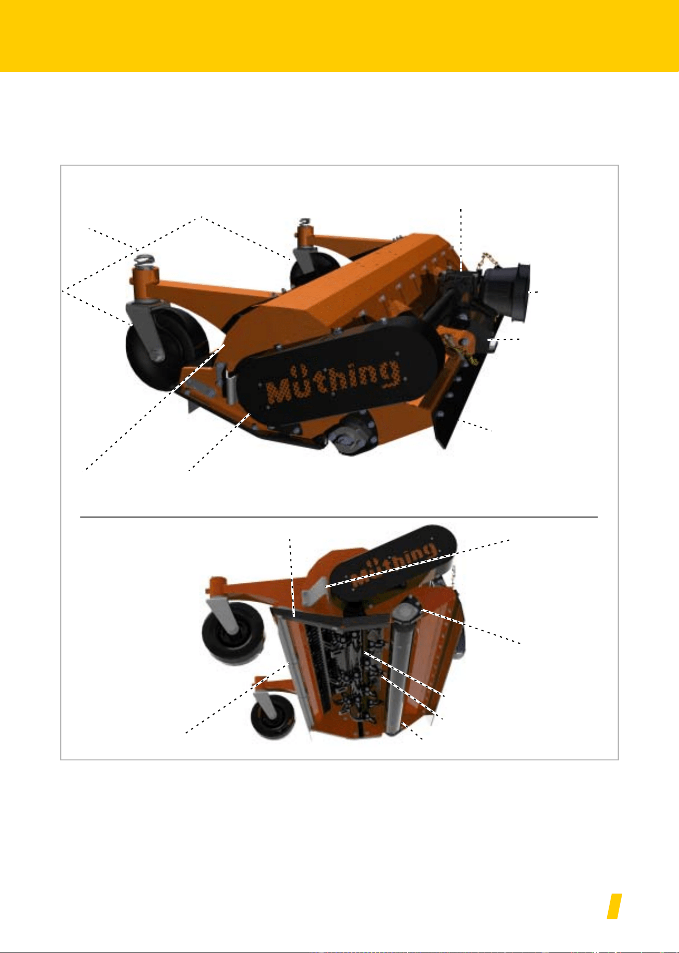
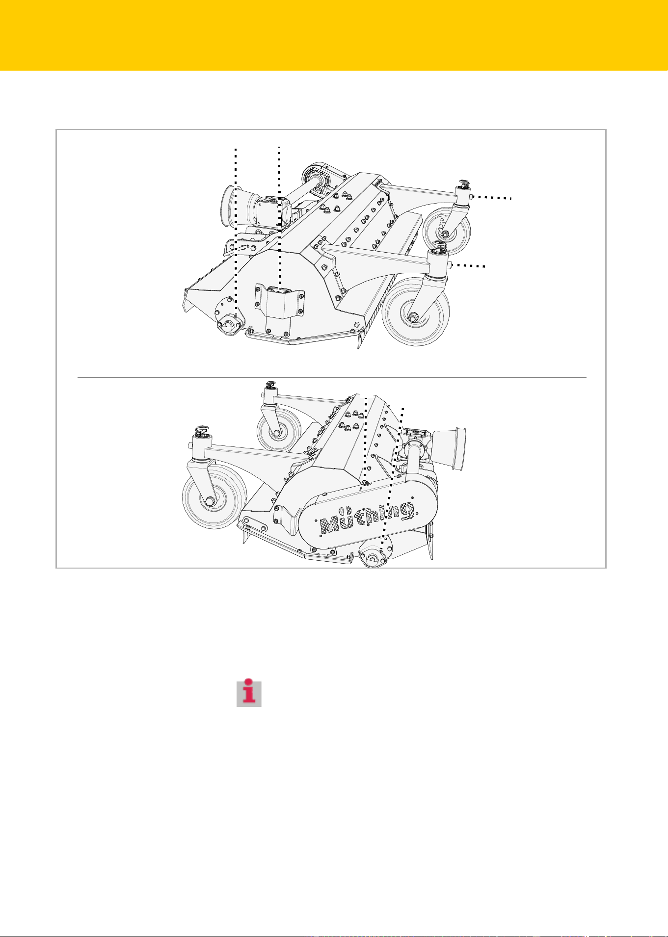
Designation of
components
Mechanical drive
Front stone impact
protection
Front support
wheels [+]
Deflector
Roller
Tool
Working depth adjus-
ter
Runner
Rotor
Connection for
PTO shaft to car-
rier vehicle
Rear stone impact
protection
Protective cover
for V-belt
Housing
Gear box
Connection to carrier
vehicle Connection
for the lower link here

MU-C HUS
24
Familiarising yourself with the machine
Technical specifi-
cations
Mechanical drive
Height
Width
Depth
MU-C HUS 120
Height (m)
Without support wheels 0.72
With support wheels 0.72
Width (m)
In work position 1.40
In transport position 1.40
Depth (m)
Without support wheels 0.85
With support wheels 1.16
Working width (m)
In work position 1.20
Total weight (kg)
Without support wheels 150
With support wheels 180
Centre of gravity (dimension G)
Without support wheels 0.39
Depending on equipment level, approx. 0.47
Rotational speed of rotor (rpm)
PTO stub shaft 1000 2000 rpm 2660
Power requirement (kW)
Minimum 9
Maximum permitted 26
Working depth (mm)
Without support wheels, in 10 mm steps 16-55
With support wheels, in 15-mm steps 16-55
Number of tools
Carbide M shackle flails 20
Lubricants
Gearbox oil SAE 75W-90
fully synthetic

MU-C HUS
25
Familiarising yourself with the machine
Category
KAT 1
Paint colors
Orange NCS S 1080-
Y70R
Black RAL 9005
PTO shaft
Model GE2101
Noise level (dbA)
In the workplace < 85
MU-C HUS 120

MU-C HUS
26
Delivery and assembly
Delivery and assemb ly
Checking the
scope of delivery
The machine is delivered completely assembled. If parts of the machine
have not been assembled, please contact your dealer.
If parts are missing or have been damaged during transportation, plea-
se submit a claim immediately to your dealer, importer or the manufac-
turer.
Do not assemble the machine yourself
Do not perform assembly work yourself since requirements for an
orderly condition of the machine are :
• Observance of a sequence of worksteps
• Compliance with tolerances and torques
Incorrect assembly may result in damage to the machine or poor
performance.

MU-C HUS
27
Coupling the machine
Coupling the machine
Adapter
The machine must be fitted with a suitable adaptor in order to be atta-
ched to a carrier vehicle. Before attaching the machine, you should the-
refore check whether the correct adaptor for your carrier vehicle is pre-
sent on the machine. Only use carrier vehicles from the list below.
If you do not have the correct adaptor:
Husqvarna-Adapter
For attachment of front-mounted implement to carrier vehicles
• P 520D
• P 525D
Contact your dealer or the manufacturer. They will be able to
supply the correct adaptor.
MU-C HUS
28
Coupling the machine
Check that the machine is securely positioned. The support wheels
and runners should be on the ground.
Chapter »Parking and storage«, section »Setting down the machine
in a secure position«, page 36
If the machine is not securely positioned:
Implement triang-
les
Requirement: Your carrier vehicle is fitted with an implement triangle
and the machine is fitted with the corresponding receiver.
Drive the carrier vehicle up to the receiver on the machine so that it
is centrally positioned.
Lower the implement triangle on the carrier vehicle so that it fits un-
der the receiver on the machine.
Drive the carrier vehicle up to the receiver on the machine.
Raise the implement triangle, making sure that it latches into the re-
ceiver securely.
Secure the implement triangle in the receiver.
Implement triangle operating instructions
Increased risk of injury
There is an increased risk of injury when the machine is being cou-
pled to the carrier vehicle. Therefore:
• Secure the carrier vehicle so that it cannot roll away.
• The carrier vehicle must be fitted with an adaptor for the
machine.
• Never stand between the carrier vehicle and the machine during
coupling.
• Actuate the power lever slowly and carefully.
Failure to observe these instructions can result in serious or fatal in-
jury.
Machine for front mounting only
The machine is only allowed to be attached to the carrier vehicle at
the front.
You can damage the machine if you mount it at the rear.
Secure the machine with suitable lifting gear and move into the
correct position
Support wheels
[+]
Runners
MU-C HUS
29
Coupling the machine
Mechanical drive
The PTO shaft has been adapted by your dealer in line with your carrier
vehicle.
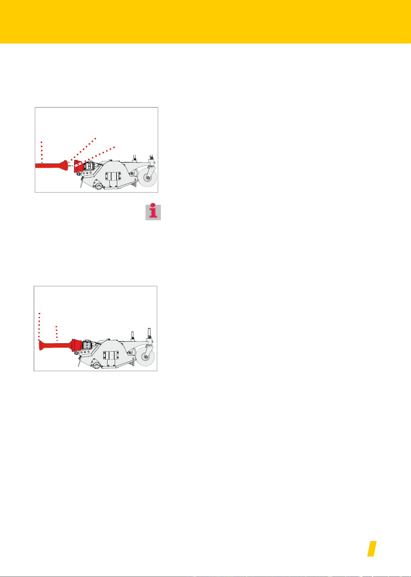
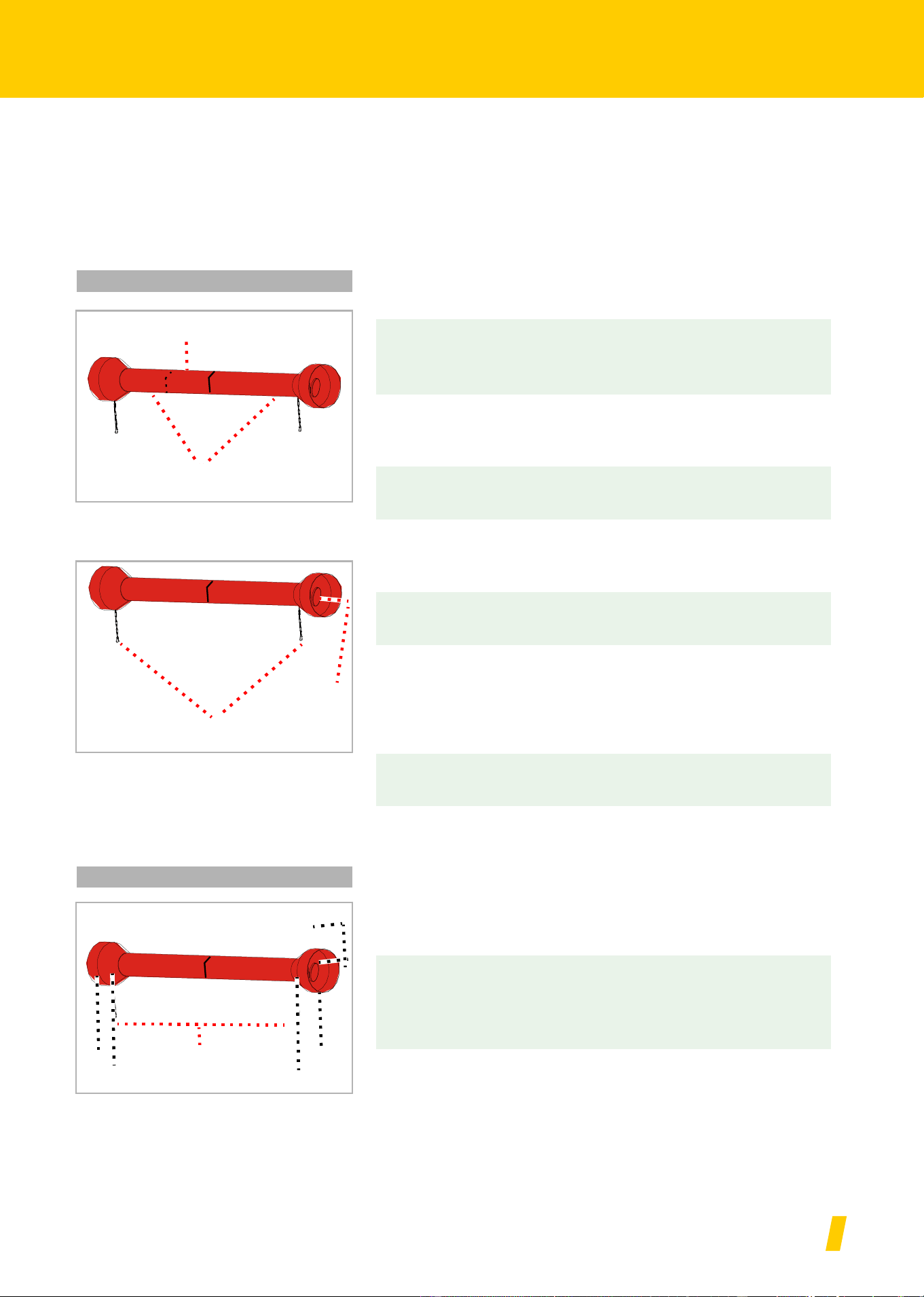
PTO shaft
Generally, the PTO shaft is already connected to the machine. If the
PTO shaft is replaced or after maintenance work to the PTO shaft, it will
be necessary to connect it to the machine.
Carefully clean and grease the PTO shaft and connection to the ma-
chine
Push the PTO shaft onto the connection to the machine and ensure
that the cotter pin locks into place on the PTO shaft
Connection to carrier ve-
hicle
If you switch to a different carrier vehicle, you must check that the PTO
shaft is the right length. It is particularly important when checking the
PTO shaft to ensure that the two halves of the PTO shaft continue to
overlap at the position in which the PTO shaft is pulled apart furthest.
If you switch to a different carrier vehicle, you must make sure that the
PTO shaft is suitable for the new carrier vehicle. If necessary, you must
swap the PTO shaft for a new one and have it adapted in a qualified
specialist workshop.
Connect the PTO shaft to the PTO stub shaft of the carrier vehicle.
Make sure that the safety split pin on the PTO shaft latches into pla-
ce.
Connection to
the machine
PTO shaft
Cotter pin
Cotter pin
PTO shaft
MU-C HUS
30
Preparation
Preparation
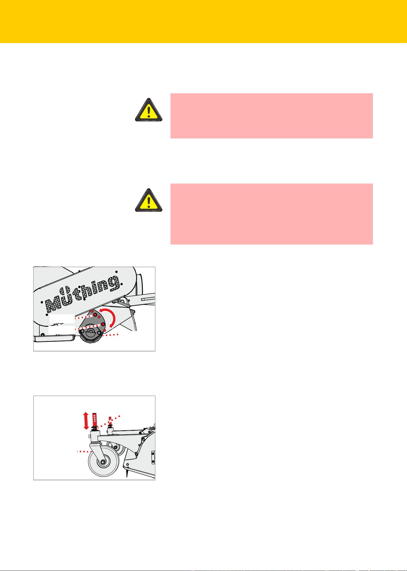
Working depth
Without support wheels, the working depth can be adjusted in 10 mm
steps. With support wheels, the working depth can be adjusted in
15 mm steps.
The optimal working depth for most applications is the middle setting.
Secure the carrier vehicle so that it cannot roll away.
Raise the machine approximately 5 cm
Without support
wheels
Undo and remove the nuts on bolt 1 and bolt 2.
Remove bolt 1 and bolt 2.
Use the adjustment plate to adjust the working depth as desired.
Secure the adjustment plate with bolt 1 and bolt 2.
Secure bolt 1 and bolt 2 with nuts.
Make the same adjustment on the opposite side of the housing.
With support wheels
[+]
Remove the cotter pin.
Raise or lower the support wheel as required.
Secure the support wheel again using the cotter pin.
Make the same setting on the second support wheel.
Tools must not come into contact with the ground
Any contact with the ground could result in stones or other material
not being held back safely by the stone impact protection.
Persons even outside of the hazard area could be injured by ejec-
ted material.
Always secure the adjusting plate with two screws
The adjustment plate must always be secured with two bolts. If the
adjustment plate is only secured with one bolt, the working depth
could change by itself and the tools could come into contact with the
ground.
Persons even outside of the hazard area could be injured by ejec-
ted material.
Bolt 1
Bolt 2
Adjustment
plate
Higher working
depth
Shallower working depth
Support wheel
Cotter pin
MU-C HUS
31
Driving on the road
Driving on the road
Transport position
Adjust the height of the lower links using the power lever of the car-
rier vehicle so that the machine is high enough for transport.
Secure the control devices on the carrier vehicle so that they cannot
be actuated accidentally.
Operating manual of carrier vehicle
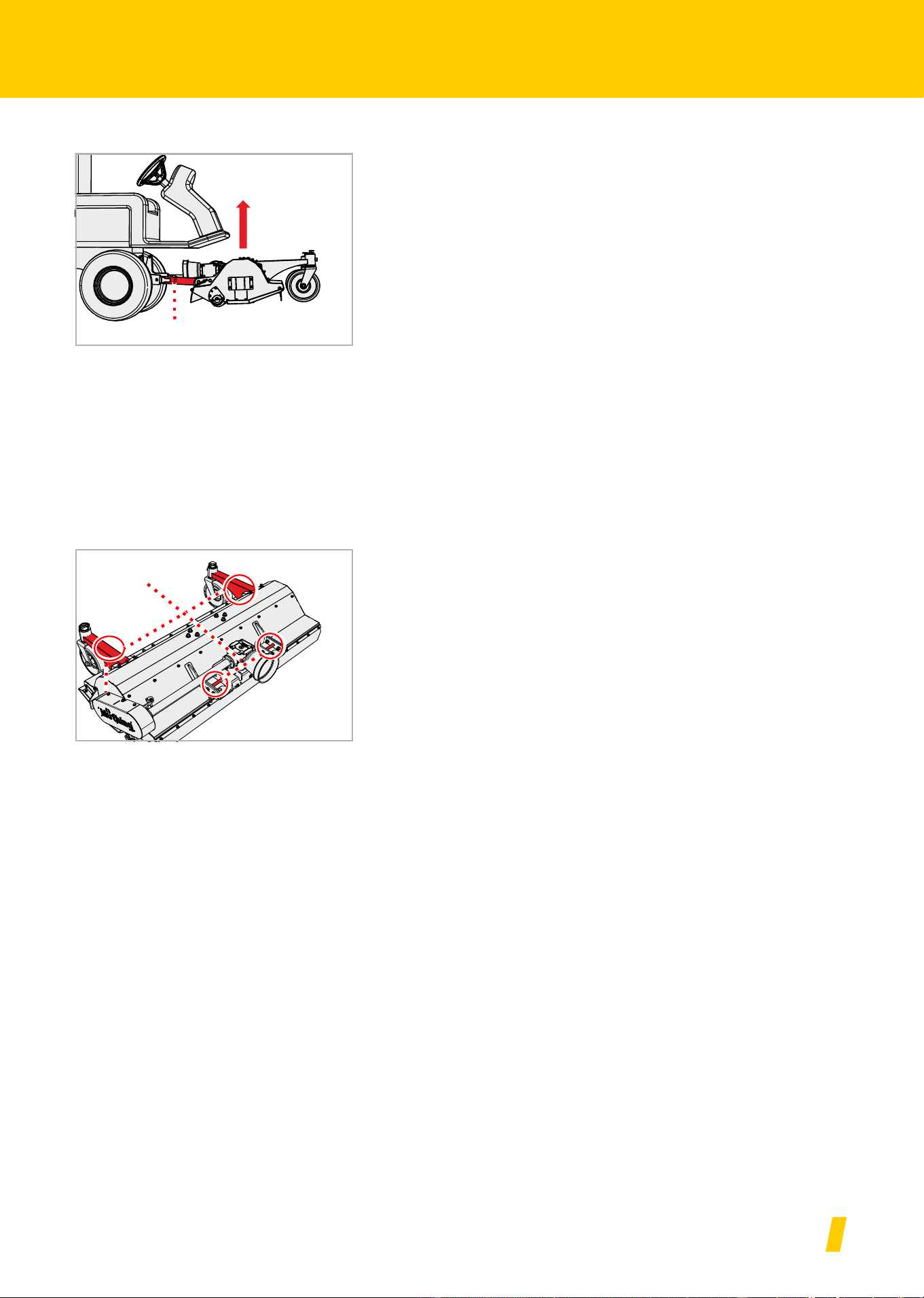
Transport without
coupling
For transport on, for example, a trailer, the machine can be raised. Only
use the designated points for attaching the lifting device. The machine
must be securely positioned.
Setting down the machine in a secure position
Chapter »Parking and storage«, section »Setting down the machine
in a secure position«, page 36
Attach suitable lifting devices to the lifting eyes
Raise the machine with suitable lifting gear and position on the loa-
ding bed
Secure the machine against slipping
Lower link
Shackles

MU-C HUS
32
Mulching
Mulching
Task
Check the hazard area
The hazard area in front of the machine is 8 m. It is 2 m at the sides.
Before driving off, operating the machine and during operation,
check its hazard area. Make sure that you have an adequate view.
Do not begin work until the hazard area is cleared of any persons
or objects.
Parts could be ejected from the machine at high speed in certain
circumstances. The hazard area, particularly in front of and behind
the machine, must be cleared of any persons, animals or objects
before starting.
Any use of the machine without verification of the hazard area can
lead to serious or fatal accidents.
Assess the dust exposure levels
If the ground and the material to be mulched are dry, you may be
exposed to dust. Dust exposure can be avoided by taking into ac-
count the direction of the wind. If dust exposure cannot be avoided,
you can protect yourself by wearing a dust mask. If these measu-
res are not sufficient, use a carrier vehicle with an enclosed cab and
a dust filter.
Dust exposure may lead to respiratory diseases.
Only work forwards
The machine may only be located in work position when moving
forwards. The machine must be raised up when reversing.
A machine in work position when reversing could result in serious
damage to the machine.
2.00 m
2.00 m
8.00 m
2.00 m
Hazard
area
MU-C HUS
33
Mulching
Particular care should be taken by the operator when working with the
mulcher. Working on ditches, overhangs or slopes are activities which
tend to be particularly hazardous. We can only give general instructions,
the actual situation must be evaluated by the operator.
MU-C HUS
34
Mulching
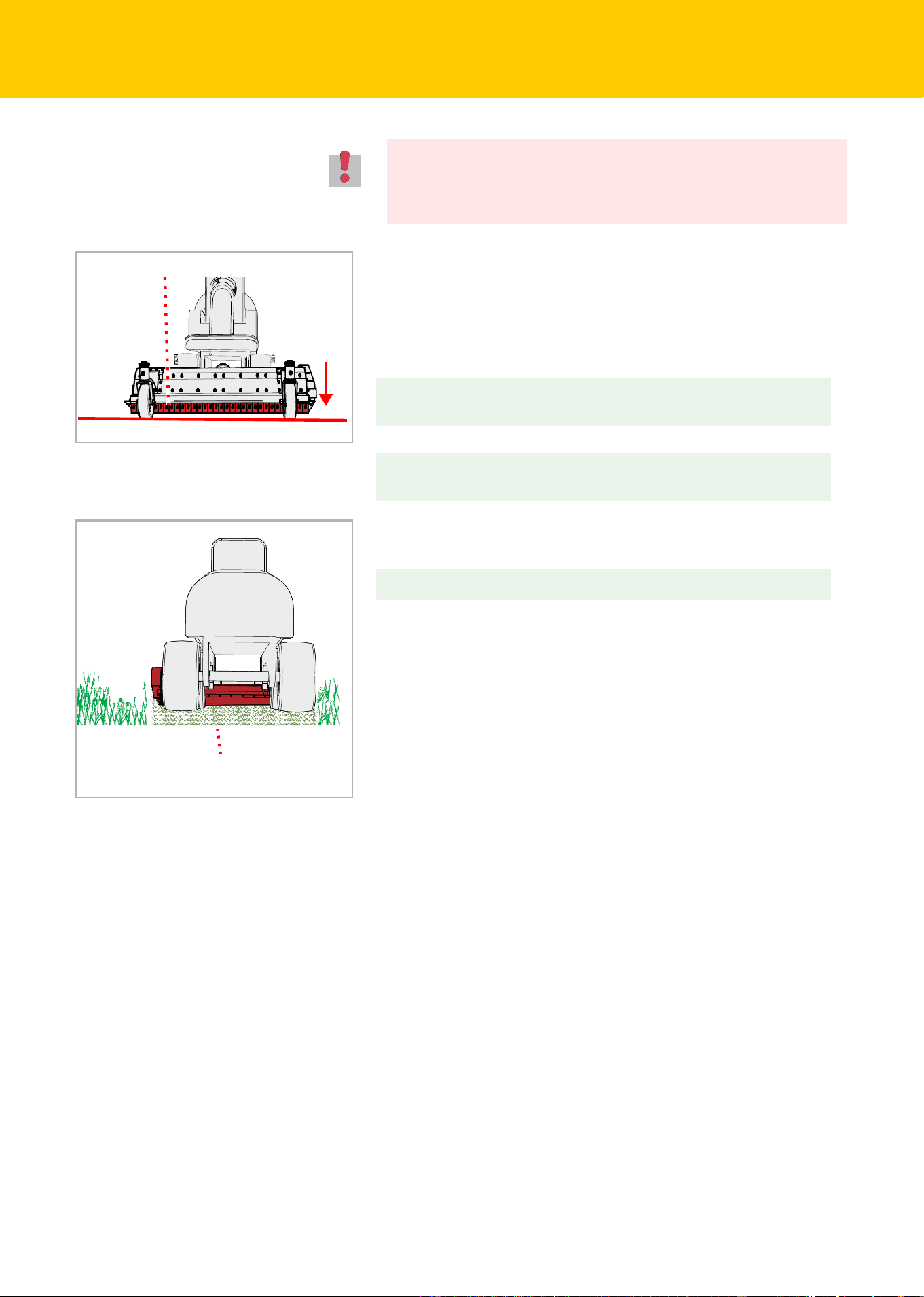
Lower the machine using the carrier vehicle until the machine is on
the ground. The front stone impact protection device should be par-
allel to the ground.
Place the control device on the carrier vehicle for the lower links into
the floating position.
In the case of machines with a mechanical drive:
In the case of machines with a hydraulic drive:
Then drive at low speed into the stock, increase speed slowly. Pay
attention to the machine while doing this.
If the machine is working too hard:
Drive at a suitable speed. The speed must be appropriate to the
growth and the type of terrain.
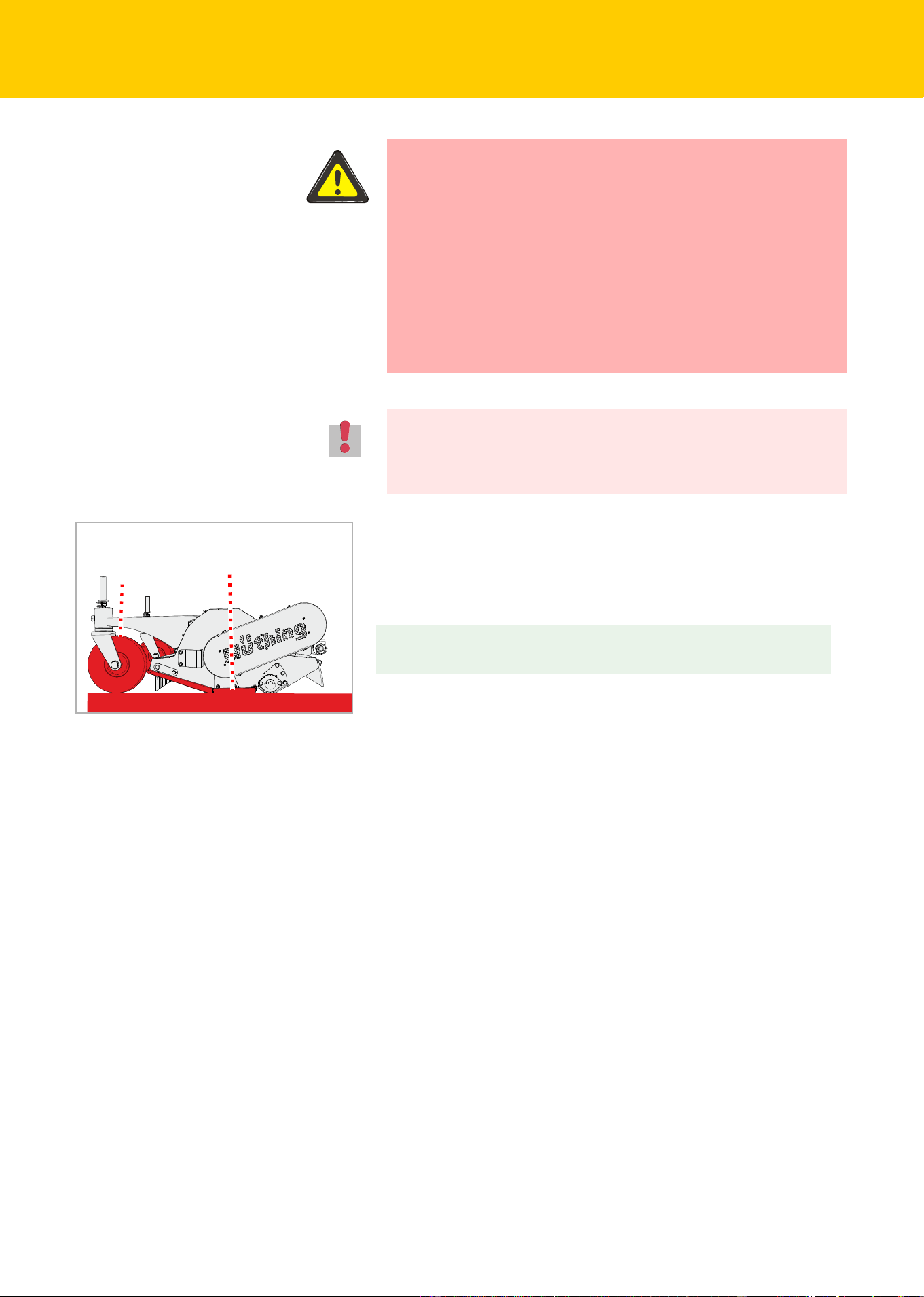
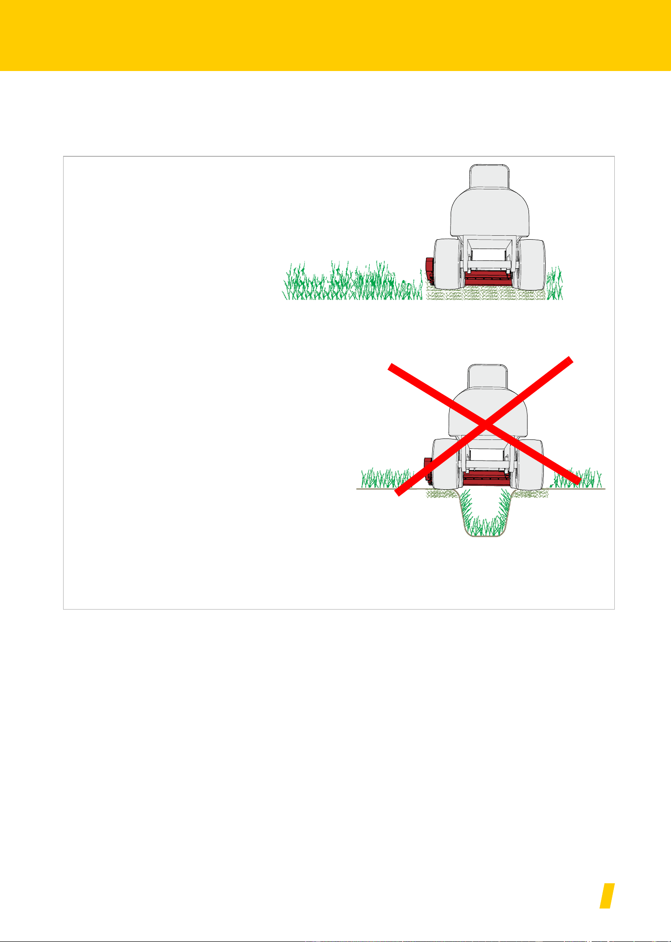
Do not lean the machine forwards
The machine must not lean forwards or backwards during work.
A machine that is leaning forwards or backwards can become clog-
ged up and work incorrectly.
Switch the PTO stub shaft into the work position and slowly
bring the machine to the rated speed
In the work position, switch on the hydraulic drive and slowly
bring the machine up to its rated speed.
Reduce speed
Front stone impact protection
Worked surface

MU-C HUS
35
Cleaning and care
Cleaning and care
Cleaning
A high-pressure cleaner, for example, can be used to clean the machi-
ne. Never point the water jet directly at the labels or type plate.
We recommend that you lubricate all bearings after cleaning. his forces
any water which has found a way into the bearings back out and increa-
ses the service life of the machine.
Care
To ensure the machine's long service life, we recommend applying a
protective coating of oil after the end of the season and during storage.
Use only approved and biodegradable oil, e.g. rapeseed oil.
Only use low pressure to clean the bearings
Only use low pressure to clean the bearings.
The ingress of water shortens the service life of the bearings

MU-C HUS
36
Parking and storage
Parking and storage
Setting down the
machine in a se-
cure position
Requirements on the set-down location:
• Horizontal, solid surface
• Sufficient room on all sides
• Protected against access by unauthorised persons, such as children
Ensure that there are no unauthorised persons can enter the
set-down location
If the machine is set down either coupled to the carrier vehicle or
uncoupled, you must make sure that it is protected so that unaut-
horised persons have no access to it.
Persons could be injured by coming into contact with parts of the
machine or by manipulating the machine.
Select the set-down location carefully
The set-down location must be relatively even and the ground must
be solid.
Uneven or soft ground could result in the machine rolling away and
becoming damaged.

MU-C HUS
37
Parking and storage
PTO shaft
Disconnect the PTO shaft from the carrier vehicle.
Adapter
Lowering the machine
Undo the retainer between the implement triangle and the receiver.
Move the carrier vehicle backwards and away from the machine.
Storing the ma-
chine
After cleaning, the machine should be stored in transport position in a
dry location and on a level and stable surface.
Section »Setting down the machine in a secure position«, page 36
Apply a protective coating of oil during storage. Use only approved and
biodegradable oil, e.g. rapeseed oil.
Chapter »Cleaning and care«, starting at page 35
PTO shaft

MU-C HUS
38
Maintenance
Maintenance
For your safety
Special safety inst-
ructions
Requirements for conducting maintenance work
Only perform the maintenance work if you have the required expert
knowledge and suitable tools.
A lack of specialist knowledge or the use of unsuitable tools can
cause accidents.
Protect the machine from being started up accidentally
If the machine is coupled, only carry out repair and maintenance
work and only rectify malfunctions on it if:
• the PTO stub shaft is off,
• the engine is switched off,
• the ignition key is removed,
Serious accidents may be caused if the machine starts accidentally.
Welding work
Welding work is only allowed to be carried out by persons trained
in welding who also have specialist knowledge of repairing landsca-
ping machinery. Welding work which negatively impacts the machi-
ne's construction is prohibited.
Incorrect welding work could impair or destroy the machine's func-
tion. If in doubt, contact your dealer before carrying out any welding
work.
Use replacement parts with identical properties
Many components have special properties that are essential for the
stability and correct operation of the machine.
When replacing components, dimensions, stability and material
quality must be guaranteed. We recommend the exclusive use of
original replacement parts.
Use of replacement parts which do not correspond to requirements
could cause damage to the machine or impaired performance.

MU-C HUS
39
Maintenance
Protective measures
when handling oils or
lubricants
Additives in oils and lubricants may have adverse effects on health. Sin-
ce the hazardous material code does not require any special identifica-
tion, please always observe the following:
• Collect old oil and dispose of it in accordance with statutory
regulations.
• If your skin becomes irritated by oil or lubricants, contact a doctor
immediately.
General informa-
tion
This information relates to general maintenance work. For all mainte-
nance work, the machine must be locked in the work position. If it is ne-
cessary to put the machine in its transport position for maintenance
work, you will see an appropriate reference in the maintenance instruc-
tions.
Working with the grease gun:
One or two strokes with the grease gun are sufficient for lubrication. If
you feel resistance during the second stroke of the grease gun, do not
complete it.
Too much grease will force the bearings apart. This could allow dust and
dirt to enter the bearing, resulting in premature wear.
Avoid skin contact
Avoid skin contact with these materials.
Contact can result in skin damage.
Protect your skin
When handling oils and lubricants, protect your skin with lotion or
wear oil-resistant gloves.
Oils can be hazardous to your health.
Do not use oils for cleaning
Do not use oils or lubricants to clean your hands.
Swarf and abraded material in these materials can also result in in-
juries.
Change out of soiled clothing
Change out of clothing that is heavily soiled with oil as soon as pos-
sible.
Oils can be hazardous to your health.

MU-C HUS
40
Maintenance
Fundamentals
The following table contains a brief explanation of the most important
terms used for maintenance.
Task Explanation
Greasing
• Apply grease to the slide surfaces
using a brush
Lubrication • Unless specified otherwise, one or
two strokes with the grease gun provi-
de sufficient lubrication
Oiling
• Unless otherwise specified, use only
vegetable-based oil such as rapeseed
oil
• Mineral oils are not suitable
• The use of used oil will endanger your
health and is also strictly prohibited
Replacement • Replace the component in question ac-
cording to the instructions in the
»Maintenance« chapter
Check
• An inspection may be required in con-
junction with the replacement of the
component in question
Observe the mainte-
nance intervals
• All information is based on average
machine usage
• In the case of heavy usage (e.g. con-
tract work), shorten the maintenance
intervals accordingly
• Shorter maintenance intervals may al-
so be required under extreme working
conditions (e.g. heavy dust generation)

MU-C HUS
41
Maintenance
Screwed connec-
tions
Retighten screws
All bolts must be retightened:
• After the first hours of operation
• According to the frequency of use
• But at least once a season
General tightening torques
Tighten all screwed connections in accordance with the information in
the table. If different tightening torques are necessary, they are speci-
fied in the chapter »Maintenance«. The minimum quality of the bolts is
8.8.
Bolt size
Quality of the bolts
„8.8“ „10.9“ „12.9“
Tightening torques in Nm
M6 9.9 14 17
M8 24 34 41
M10 486881
M12 85 120 145
M16 210 290 350
M20 425 610 710
M24 730 1050 1220

MU-C HUS
42
Maintenance
Maintenance inter-
vals and setting
work
The information relates to average usage under the machine's normal
operating conditions. Maintenance intervals are shorter for heavy usa-
ge, such as with hire companies, or for extreme operating conditions
such as very dusty environments.
After the first hours of operation
Once daily
After 30 hours of operation
After 75 hours of operation
Once per season
As required
In case of wear
grease / oil / lubricate
Check
Replacement
Cleaning
General
Retighten all screws • •
Visual inspection ••
Bearing • • •
Pivots ••
Tools
Fastenings on the rotor ••
Condition, wear • • •
Other
Position of rotor • •
Roller bearing ••
Shafts and pins • •
PTO shaft
Protective cover
•
•
•
•
•
•
•
•
•
•
•
•
Gearbox oil • •
••

MU-C HUS
43
Maintenance
Lubricating work
Lubricate bearings
The bearings must be lubricated regularly. Lubricate only with one or
two strokes from the grease gun:
• According to the maintenance chart
• After heavy use
• But at least once a season
Bearings that require no maintenance must not be lubricated.
MU-C HUS
44
Maintenance
Overview of lubrica-
tion points
Other lubrication
points
The following applies:
• In addition to the lubrication points shown in this operating manual,
your machine may have other lubrication points
• As a rule, lubrication points are located at pivots or bearings. There-
fore, inspect your entire machine for any such additional lubrication
points.
The location of the lubricating nipple is usually shown on one compo-
nent as an example. If multiple components of this kind exist, the lubri-
cating nipples have to be lubricated at each of these components.
S = lubrication point
S
S
S
S
S
S
MU-C HUS
45
Maintenance
PTO shaft
The PTO shafts are heavily stressed. This means that regular mainte-
nance is decisive for the PTO shafts' service life. Only the most import-
ant work is shown here.
Full maintenance work on the PTO shaft:
PTO shaft operating manual
Checking
Check the PTO shaft for contamination and clean if required. Dust in
conjunction with oil and grease results in increased wear
If the PTO shaft is heavily contaminated:
Check protective cover for damage
If the protective cover is damaged:
Check presence and correct function of safety chains
If the safety chains are not present or are heavily worn:
Check the PTO shaft for wear in the universal joints and at the con-
nection to the PTO stub shaft
If the universal joints are heavily worn:
Lubrication
In case of heavy usage or in extreme operating conditions, such as a
very dusty environment, more frequent lubrication is required.
Lubricate in the universal joint with 1 - 2 strokes of the grease gun.
Lubricate on the slip rings with 1 - 2 pumps of the grease gun
For wide-angle PTO shafts:
Daily
Clean PTO shaft
Grease the interior of the overlap area of the protective cover
PTO shaft operating manual
Replace protective cover
PTO shaft operating manual
Replace the safety chains
PTO shaft operating manual
Replace the universal joints
PTO shaft operating manual
Protective
cover
Overlap area
Safety
chains
Universal joint
and connec-
tion to PTO
stub shaft
Every 50 hours of operation
The wide-angle joint contains a lubricant reserve which must be fil-
led with 400-500 g [14-17 OZ] of grease.
Lubricate with at least 5-6 pumps of the grease gun
PTO shaft operating manual
S
S
S
S
S
Slip ring lubrica-
tion points
MU-C HUS
46
Maintenance
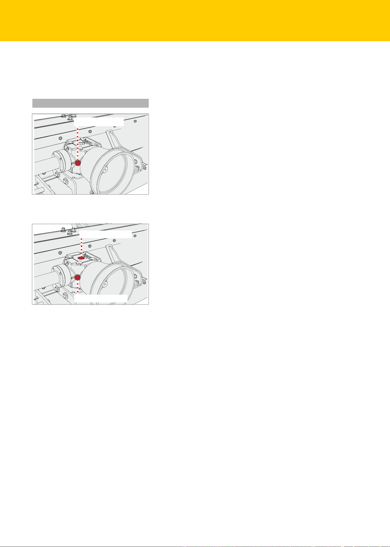
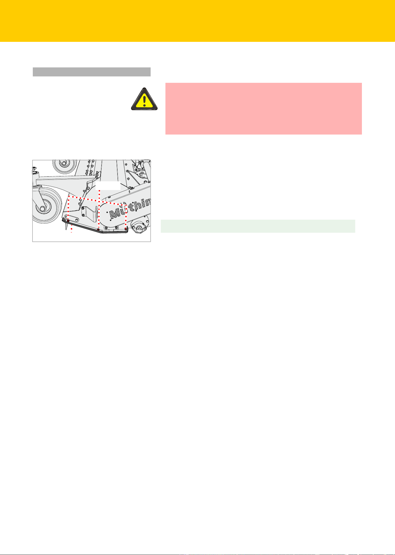
Gearbox oil
The gearbox oil must conform to the specification.
Chapter »Familiarising yourself with the machine«, section »Techni-
cal specifications«, page 24
Check
Loosen the screw on the inspection opening with an Allen key and
remove the screw
Check the oil level. The oil level must reach the lower edge of the in-
spection opening.
Retighten the screw at the inspection opening
Refilling
Loosen the screw on the inspection opening with an Allen key and
remove the screw
Loosen the screw on the filler opening with an Allen key and remove
the screw.
Use a funnel to fill with gear oil of the appropriate specification until
the oil level reaches the lower edge of the inspection opening
Retighten the screw at the inspection opening
Retighten the screw at the inspection opening
Twice per season
Inspection opening
Inspection opening
Inspection opening
MU-C HUS
47
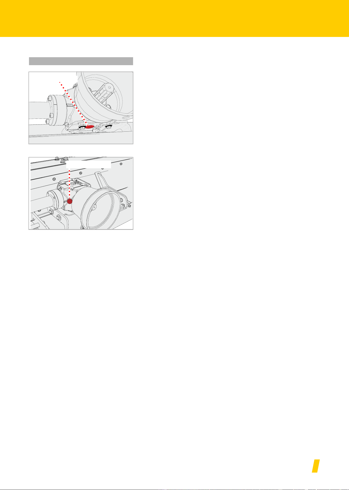
Maintenance
Replacement
Place a collection container under the outlet for the waste oil
Loosen the screw on the inspection opening using a hex key
Loosen the screw on the outlet with an Allen key and remove the
screw
Allow the oil to drain out fully
Screw the screw on the outlet back in.
Refill with new gear oil
Section »Refilling«
1x per season
Outlet
Inspection opening
MU-C HUS
48
Maintenance
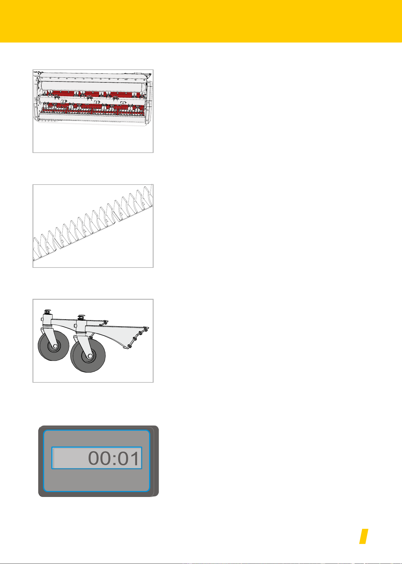
Tools
The tools must be replaced if they:
• Are damaged
• Are heavily worn
• The bore on the tool is worn
• The fastening screws or the fastening nuts are worn
It is important that the rotor runs without unbalance. Therefore:
• Always replace tools with the same type
• Always replace tools opposite each other at the same time
• In case of wear it is best to replace the entire set of tools
Secure the machine against rolling away and dropping
Loosen the nuts and remove the bolts
Remove old tool
Insert the new tool in the same way.
Fit a new screw and secure with a new nut
As required
Secure the machine
Work can only be carried out on a machine secured against rolling
away and dropping. To prevent dropping, for example, permitted
and correctly dimensioned support legs can be used.
If the machine is not secured against rolling away and lowering, se-
rious or fatal accidents could result.
New tools – new nuts and bolts
When replacing the tools, the nuts and bolts must also be replaced.
If the nuts and bolts are not replaced, the worn bolts may break.
Tools may become detached during work and be flung out. Even
persons outside of the hazard area could be seriously injured or kil-
led.
Rotor
Tool
Bolt
Nut
MU-C HUS
49
Maintenance
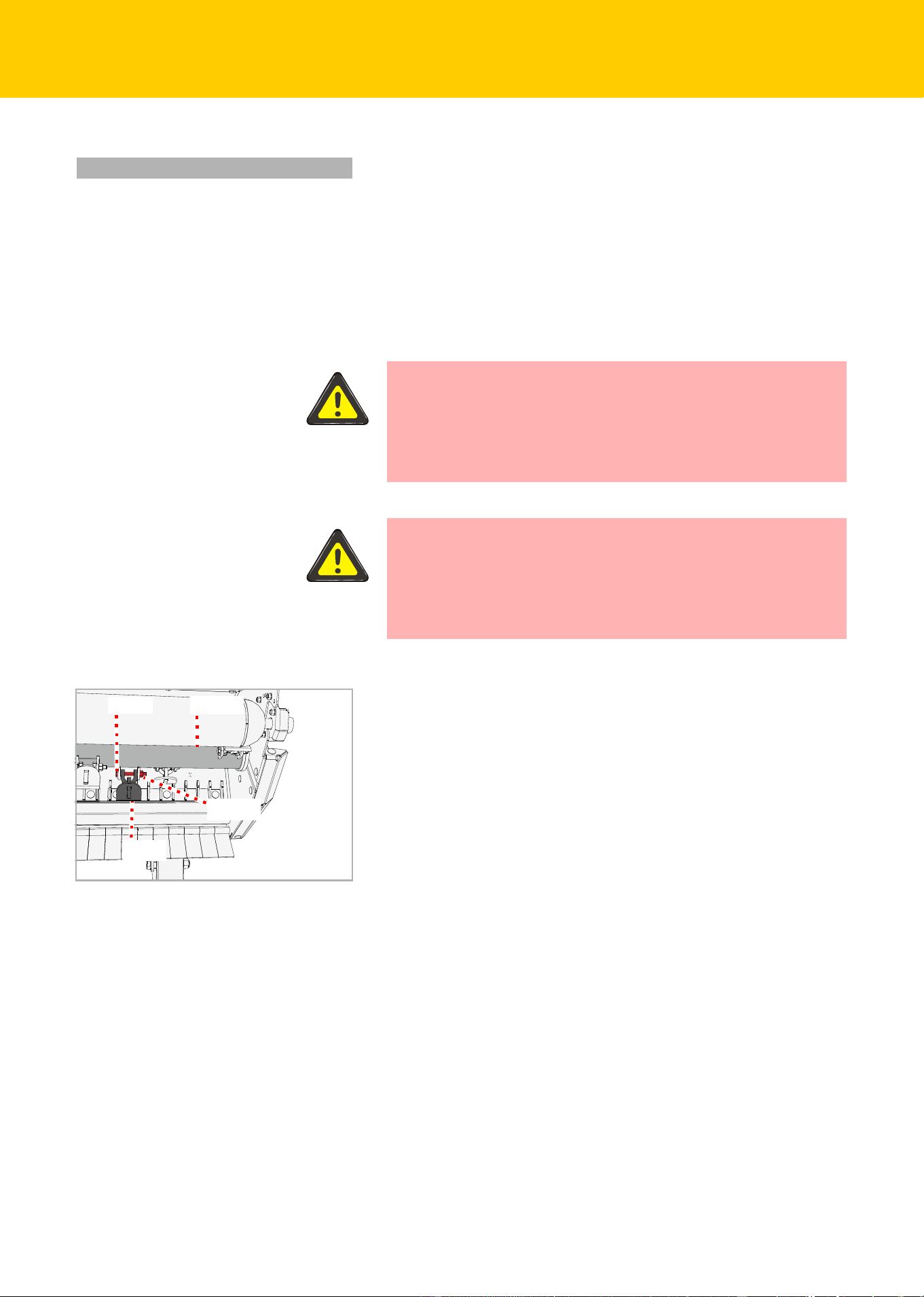
V-belt
The V-belt is tensioned by a counterweight. If the V-belt is not sufficient-
ly tensioned, it must be retensioned. If there are any tears or the V-belt
is damaged, it must be replaced.
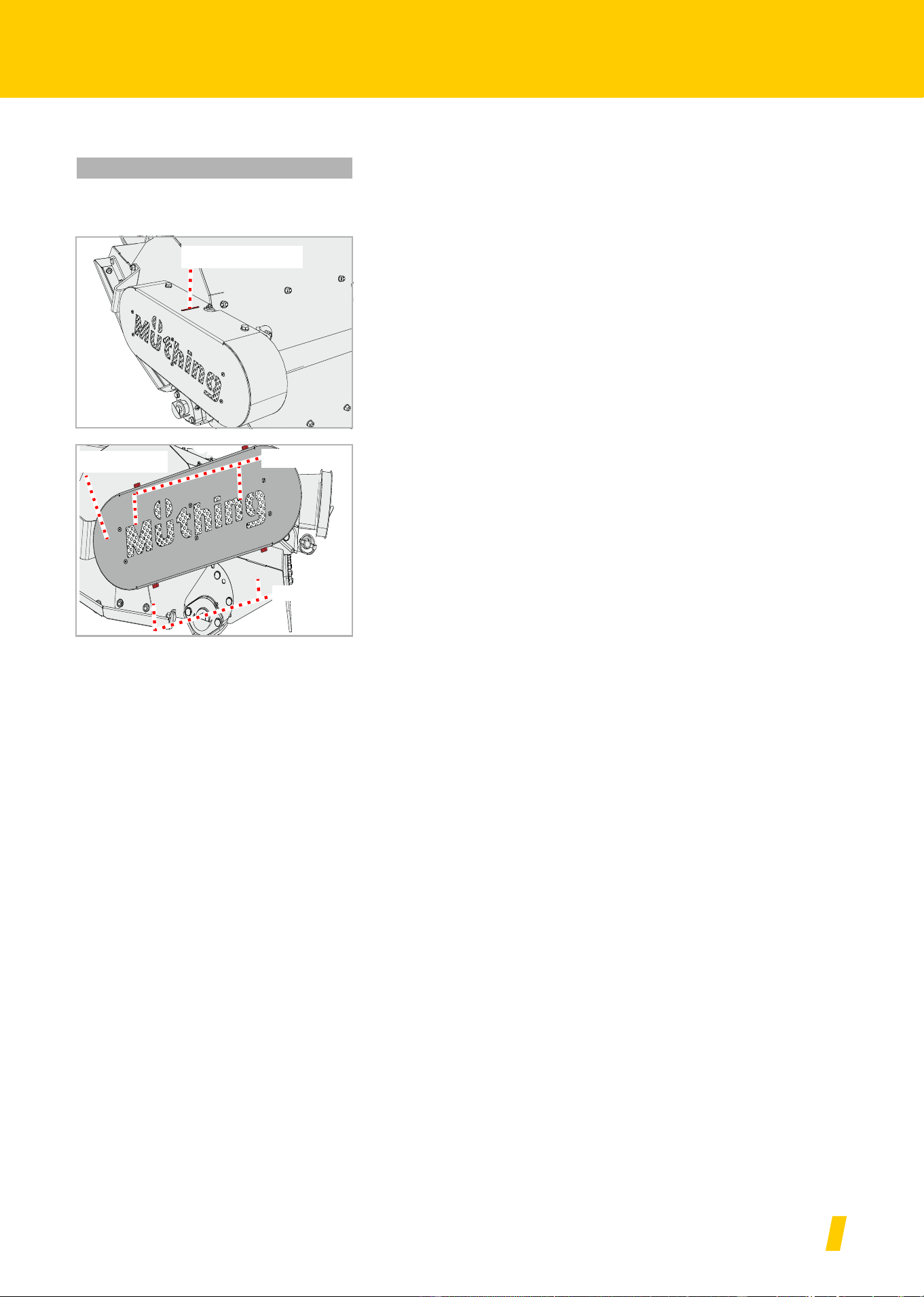
Checking
There is an inspection opening on the machine.
Check the tension of the V-belt. When under a load of 6 kg, it must
not be possible to push the V-belt through more than 10 mm.
Remove the screws, remove the safety cover.
Check the V-belt for damage
Reassemble the safety cover
As required
Inspection opening
Screws
Screws
Safety cover
MU-C HUS
50
Maintenance
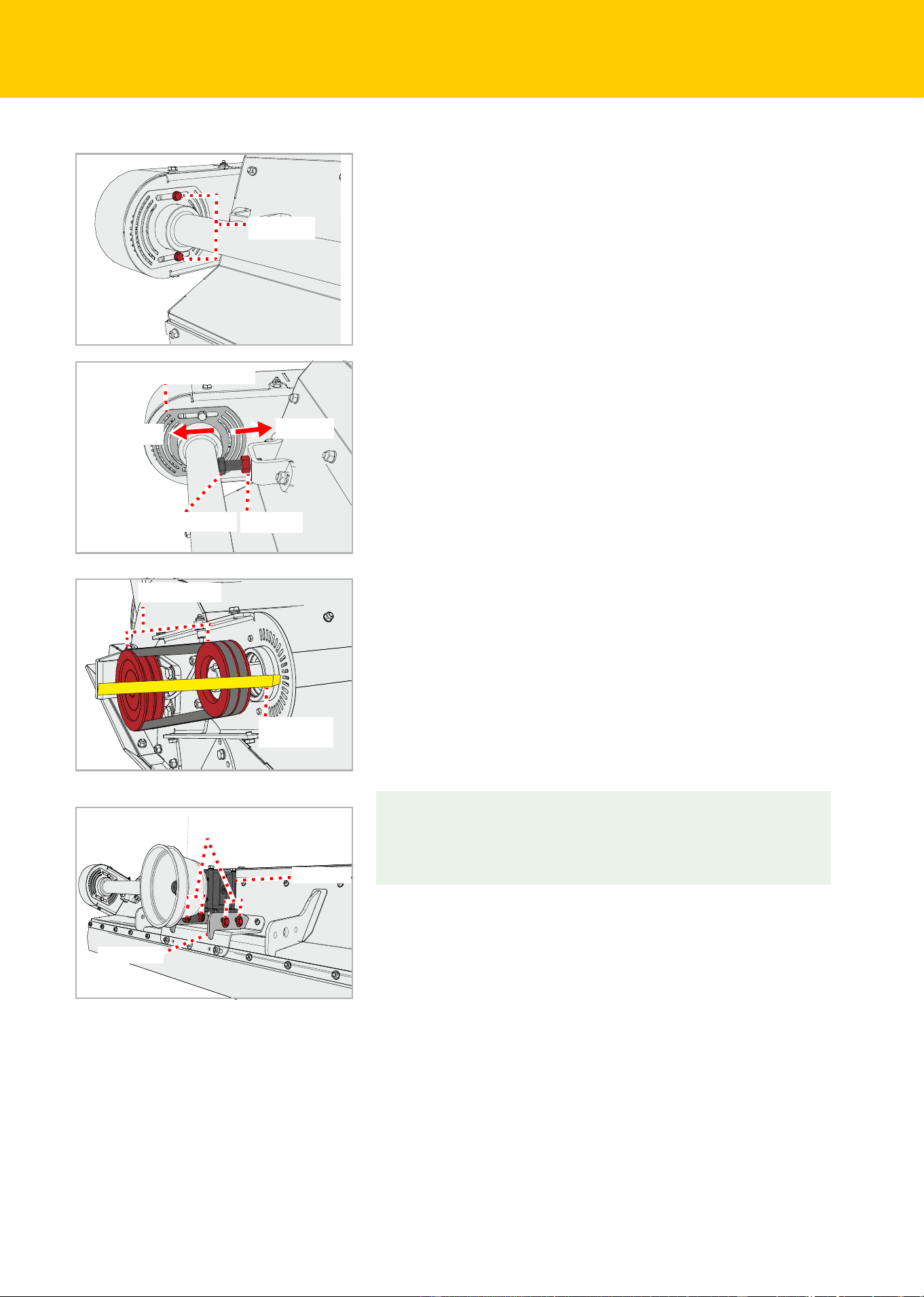
Tensioning
Loosen the nuts but do not remove them.
Loosen the lock nut.
Use the bolt to set the V-belt tension as required via the counter-
weight
Tighten the lock nut again.
Check the alignment of the V-belt pulleys. Use a surveyor's staff or
similar. The surveyor’s staff must lie flat on both V-belt pulleys and
must be properly aligned.
If the surveyor's staff does not lie flat:
Check the tension of the V-belt
Undo the nuts on the bolts.
Move the holder with the gear-box until the surveyor's staff lies
flat on both V-belt pulleys
Retighten the nuts on the bolts.
Bolts
Counterweight
Bolt
Lock nut
Release
Tensioning
Surveyor's
staff
V-belt pulleys
Gear box
Bracket
Bolts with nuts
MU-C HUS
51
Maintenance
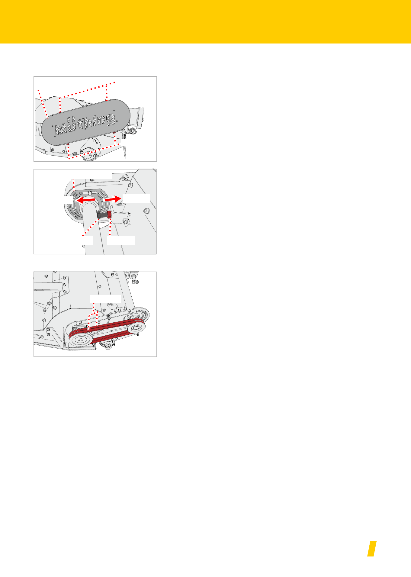
Replacement
If there are any tears or other damage on the V-belt, it must be replaced.
Remove the screws, remove the safety cover.
Loosen the lock nut.
Use the bolt to slacken the V-belt tension
The V-belt unit consists of two narrow V-belts.
Remove the old V-belts
Fit the new V-belts
Check the V-belt for correct positioning
Tension the V-belt
Section »Tensioning«, page 50
Reassemble the safety cover
Screws
Screws
Safety cover
Counterweight
Bolt
Lock nut
Release
Tensioning
V-belt
MU-C HUS
52
Maintenance
Runners
The runners protect the machine from direct contact with the ground. If
they are not replaced in good time, the housing of the machine will be
damaged.
Runners
There are runners on the right-hand side and left-hand side.
Undo nuts, remove screws and washers.
Remove old runner
Fit new runner
Fit new screws and washers
Secure screws with new nuts
If the runners also need to be replaced on the opposite side:
As required
Secure the machine
Work can only be carried out on a machine secured against rolling
away and dropping. To prevent dropping, for example, permitted
and correctly dimensioned support legs can be used.
If the machine is not secured against rolling away and lowering, se-
rious or fatal accidents could result.
Replace the runners on the opposite side as well.
Screws
Runner
MU-C HUS
53
Additional equipment
Additional equ ipment
Wear insert
A metal insert protects the housing from wear.
Counter cutter
A second counter-cutter optimises the material feed. This produces bet-
ter cutting. This produces better cutting.
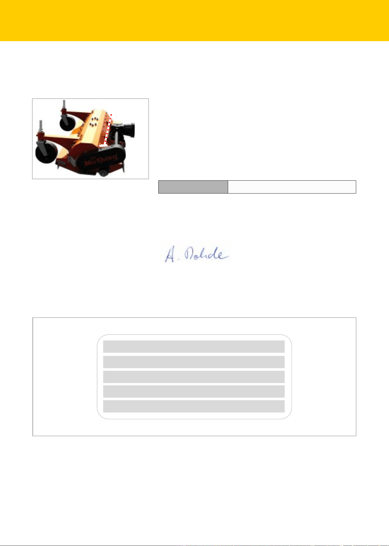
Support wheels
Support wheels are available for comfortable depth guidance.
Operating hours
counter
An electronic operating hours counter displays the actual operating du-
ration. This means that data can be recorded precisely and used, for
example, for calculations.

MU-C HUS
54
Fault elimination
Fault elimination
Faults can often be eliminated quickly and easily. In the event of hydrau-
lic problems, first check:
• Are the hydraulic hoses properly connected?
• Is the control valve on the carrier vehicle defective?
If so, contact your dealer.
• Is the hydraulic pump of the carrier vehicle defective?
If so, contact your dealer.
Before calling Customer Service, refer to the table below to check whet-
her the fault is one you can eliminate yourself.
Fault Cause Remedy
Strong vibrations and high noise
development
Tools are worn Replace the tools
One or more tools are missing Replace tools
Tools are damaged Replace the tools
Bearings for the rotor are worn Have the bearings replaced
Foreign bodies, such as wire, are
wound around the rotor
Remove foreign bodies
Tools have become loose Tighten nuts on screws
Speed of rotation of the PTO stub
shaft is not set correctly
Set the correct speed of rotation on
the PTO stub shaft
Rotor not correctly counterbalanced Check balancing and rebalance the
rotor if necessary
Tools wearing quickly The tools are working too deeply Set correct working depth
Material cut too rough and cut ma-
terial not distributed evenly
Drive speed too high Reduce the drive speed
The tools are working too deeply Set correct working depth
The tools are working too high Set correct working depth
V-belt worn Replace V-belt set
V-belt not correctly tensioned Check V-belt tension and retension
if necessary
The speed of the PTO stub shaft of
the carrier vehicle is too low.
Increase the rpm
Tools are worn Replace the tools
The machine is not standing parallel
to the ground
Adjust the machine correctly
Rotor does not turn Rotor is blocked by a foreign body Remove foreign bodies
The PTO shaft is free-wheeling or
the gear box is incorrectly assem-
bled.
Have the free running state cor-
rectly assembled

MU-C HUS
55
Fault elimination
PTO shaft rotating, rotor is not V-belt torn Replace the V-belt
Unusual noises from the PTO shaft Insufficient lubrication Lubricate the PTO shaft
Gear box overheating Incorrect oil specification Change oil and select oil with cor-
rect specification
Oil too old Change oil
Oil level too low Fill the oil to the lower edge of the
inspection opening
Machine overload Maintain rpm in correct region, ad-
just driving speed to suit the work,
maintain performance area (avoid
excessively heavy growth or exces-
sively thick branches)
High wear on V-belts
V-belts running hot
Power transmission not optimal
The tools are working too deeply and
touching the ground
Set correct working depth
Pulleys not aligned in parallel Have pulleys correctly aligned
V-belt is worn Replace the V-belt
V-belt is not correctly tensioned Check the tension jack
Oil leaking from the gear box Sealing rings worn or damaged Have sealing rings replaced
Drive elements broken Machine was started up abruptly or
is blocked by foreign bodies
Have defective drive element repla-
ced. Start the machine up slowly.
Fault Cause Remedy

MU-C HUS
56
Disposal of the machine
Disposal of the machine
When the service life of your machine is over, it must be disposed of
properly. Please observe currently valid disposal regulations.
Metal parts
All metal machine components can be sent for metal recycling.
Plastic parts
All plastic parts are marked and can be recycled.
Oil
Collect fluid from the hydraulic system in a suitable container and dis-
pose of at a used oil collection facility.

MU-C HUS
57
EC Declaration of Conformity
EC Declaration o f Conformity
EC Directive
2006/42/EG
Müthing GmbH & Co KG Soest
Am Silberg 23
D-59494 Soest
assumes sole responsibility for declaring that the following product
complies with EC Directive 2006/42/EC:
Assorted samples of harmonized standards:
• DIN EN ISO 4254-1
• DIN EN ISO 4254-12
• EN 13524
Soest, 28.10.2022
Andreas Rohde
CEO and authorised person for compiling technical documentation
Type plate and
CE symbol
MU-C HUS and additional equipment
Copy of the type plate/serial number entry
Maschine Type: Mulcher
Working width:
Serial number:
Year of construction:
Maschine Name:
MU-C HUS
58
UK Declaration of Conformity
UK Declaration of Conformity
UKCA
Müthing GmbH & Co. KG Soest
Am Silberg 23
D-59494 Soest
Germany
declares under sole responsibility that the machine conforms with the
following directives:
• Supply of Machinery (Safety) Regulations 2008
Assorted samples of harmonized standards:
• BS EN ISO 4254-1
• BS EN ISO 4254-12
• BS EN 13524
The special technical documents corresponding to the machine have
been created according to Annex VII, Part B.
Soest, 28.10.2022
Andreas Rohde
CEO and authorised person for compiling technical documentation
Machine designation MU-C Hydro and additional equipment
Type plate and
CE symbol
Copy of the type plate/serial number entry
Type of machine: Mulcher
Working Width:
Maschine ID:
Production Year:
Model:

59
Index
Index
A
Additional equipment 53
Counter cutter
53
Operating hours counter
53
Support wheels
53
Wear insert
53
Assemblies
23
C
Care 35
Centre of gravity
15
Cleaning
35
Coupling
28
D
Declaration of Conformity 57
Dimension G
15
Direction information
13
E
Employer 8
F
Fault 54
Features
22
L
labels, see warning signs
Lubricate bearings
43
M
Machine
Storing
37
Maintenance
General information
39
Maintenance intervals
42
Overview of lubrication points
44
Safety
38
P
Parking 36
Pictograms
9
Protective measures
Oils or lubricants
39
R
Range of application 21
Carbide M shackle flails
21
S
Safety 10
Agricultural training
13
Axle loads
15
Centre of gravity
15
Check the screwed connections
20
Cleaning
20
Coupling
14
Minimum ballast
15
Observe the care and maintenance intervals
19
Proper use
21
Putting the machine into operation
17
Riding on the machine
17
Take the change in driving and braking
performance into account
17
Total weight
15
Tyre load-bearing capacity
15
Uncoupling the machine
19
Warning signs
10
Welding work
20
Scope of delivery
26
Screwed connections
41
Setting down the machine in a secure position
36
Symbols
9
T
Target group 8
Task
32
Technical specifications
24
Tightening torques
General
41
Training
8
Transport
Transport position
31
Transport without coupling
31
W
Warning signs 10
Meaning
11
Working depth
30

www.husqvarna.com
11-0556_Husqvarna manual_A4.indd 2 2012-11-13 10:13
FR

