1
Installation Instructions
for your new
RAB42*
Assembly Required
Wall Sleeve for All AZ Series
Zoneline Models
Before you begin - Read these instructions completely
and carefully. IMPORTANT – OBSERVE ALL
GOVERNING CODES AND ORDINANCES. Note to
Installer – Be sure to leave these instructions with the
Consumer. Note to Consumer – Keep these instructions
with your Owner’s Manual for future reference.
NOTES:
• Handle the sleeve carefully.
• The cardboard stiffener inside the case and the
rear protective panel must remain in place until
the chassis is installed to assure case rigidity and
squareness.
• If a sub-base is to be used, it may be desirable to
assemble it to the sleeve before securing the sleeve
in the wall.
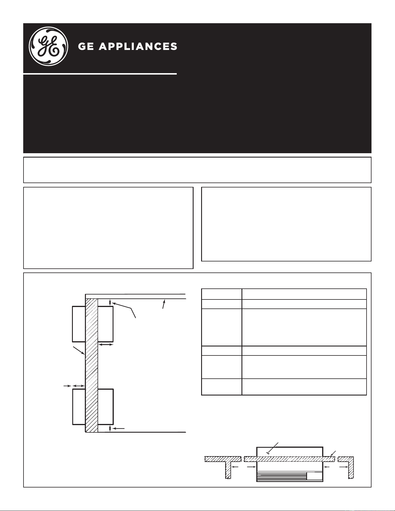
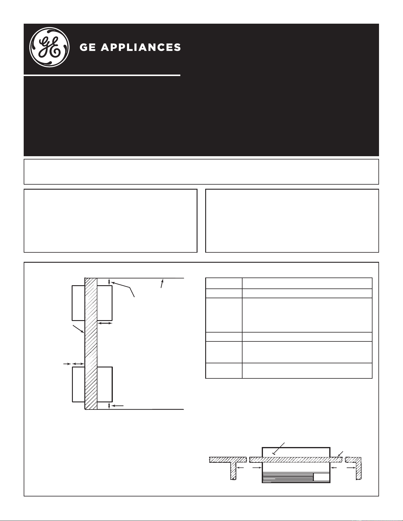
CRITICAL DIMENSIONS
Ceiling
“A”
“B”
“C”
Roomside
Outside
wall
“D”
)LQLVKHGÀRRURUWRSRIFDUSHW
NOTE: Care should be taken in location of electrical
supply entry in relationship to wall sleeve to ensure
access to power once the unit is installed.
Dimensions Recommended Installation Clearance
A 7RSRIVOHHYHWR¿QLVKHGFHLOLQJ´PLQ
B
3URMHFWLRQRIVOHHYHLQWRURRPIURP¿QLVKHG
ZDOOó´PLQQRVXEEDVHǪ´PLQZKHQ
VXEEDVHLVXVHG,IPRUHWKDQ´RIWKHVOHHYH
projects into the room, a sub-base or other
support is recommended.
C 3URMHFWLRQRIVOHHYHWRRXWVLGH´PLQ
D
+HLJKWDERYH¿QLVKHGÀRRURUWRSRIFDUSHW
´PLQZLWKRXWVXEEDVH´PLQ´PD[ZLWK
sub-base.
E Left/Right side of sleeve to adjacent wall -
´PLQ
NOTE: For sleeves with an internal drain, install level
LQDOOGLUHFWLRQV)RUVOHHYHVZLWKDQH[WHUQDOGUDLQ
LQVWDOOOHYHOOHIWWRULJKWZLWKDVOLJKWWLOWWRWKHH[WHULRU
IRUGUDLQDJHPD[LPXPWLOWóEXEEOHWRWKHH[WHULRU
SLEEVE LOCATION
Sleeve must be located on an outside wall for proper
operation. As a general rule, the air conditioner should
be centrally located in an outside wall to ensure proper
distribution of conditioned air. It should be located in
a portion of the wall where there is no electrical wiring
or plumbing, and where there are no obstructions
immediately inside or outside.
For further details, refer to the GE Appliances Architects and Engineers Design Data Manual for Zonelines. To
REWDLQDFRS\RIWKHPDQXDOFDOO*($SSOLDQFHVDWRUYLVLWXVDWZoneline.com.
Outside wall
“E”
“E”
Top of Sleeve
5HY
31-5000912 Rev. 1
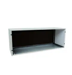
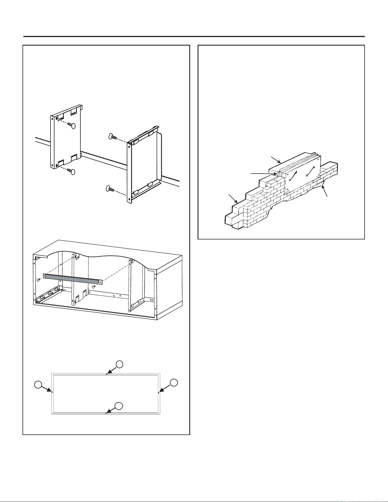
STEP 3:
Assemble the Wall Sleeve on Deep
Sleeve Models Only
$OLJQWKHDLUGLYHUWHUSDQHOVZLWKWKHWDEVRQGHHSVOHHYH
PRGHOVORFDWHGRQWKHWRSDQGERWWRPSDQHOV6OLGHWKHP
into place until the holes on the vertical surface line up.
([WHQGHGVOHHYHPRGHOQXPEHUVDUHRAB4216MG, RAB-
4218MG, RAB4220MG, RAB4224MG.
Installation Instructions
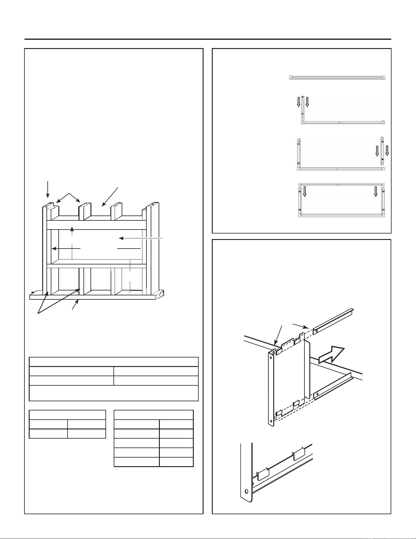
STEP 1: Preparation of the wall
The wall sleeve should be installed during construction
and lintels should be used to support the block above
the wall sleeve. The sleeve will not support the concrete
EORFNRUEULFN7KHVOHHYHLVPRGXODULQKHLJKWDQGZLGWK
+HLJKW ±)LWVFRXUVHVFRQFUHWHEORFN
– Fits 6 courses standard brick
±)LWVFRXUVHMXPEREULFN
:LGWK ±)LWVDSSUR[LPDWHO\VWXGVSDFHV
)RUH[LVWLQJFRQVWUXFWLRQZDOORSHQLQJVPXVWEHPDGH
Wall openings of the proper dimensions are essential to
DYRLGWKHQHFHVVLW\RI¿OOHUVRUDGGLWLRQDOIUDPLQJ
42
1
/
2
16
1
/4
16¼” Min.
42 ¼” Min.
“D”*
NOTE: Use lintel to support brick, block, etc., above the
DLUFRQGLWLRQHUVOHHYH,IGLUHFWO\XQGHUDZLQGRZVLOOWKH
XVHRIDOLQWHOPD\QRWEHQHFHVVDU\
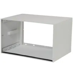
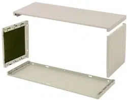
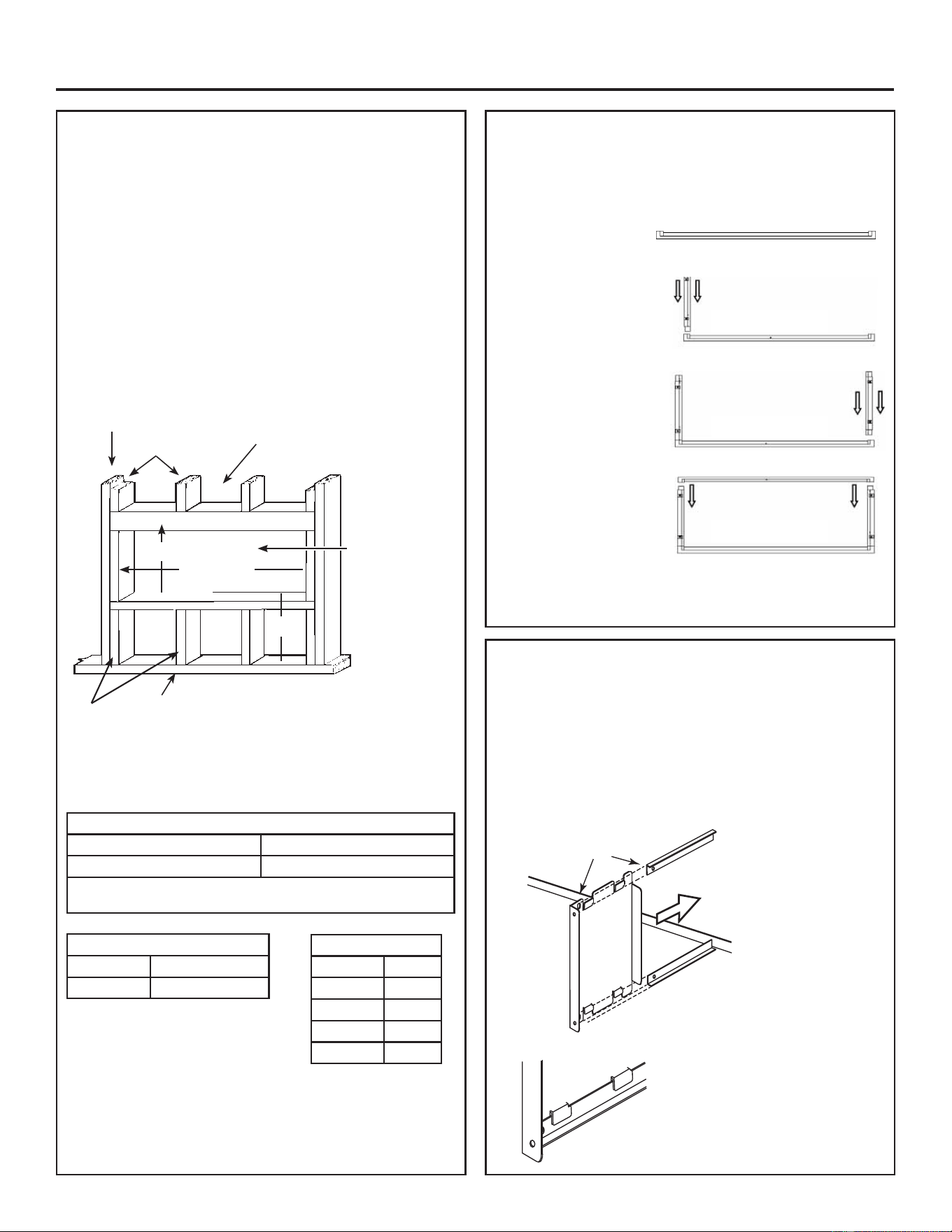
STEP 2:
Assemble the Wall Sleeve
1. Set the bottom panel
RQDFOHDQÀDWOHYHO
surface.
/RFDWHOHIWVLGHSDQHO
Align panel in the left
bottom panel slot. Insert
the left panel into the
bottom panel until all
tabs lock completely.
/RFDWHULJKWVLGHSDQHO
Align panel in the right
bottom panel slot.
Fully insert right panel
into bottom panel until
locking tabs engage.
4. Locate top panel and
align with top of right
and left side panels.
Fully insert top panel
into right and left side
panels until locking tabs
engage.
Front View
Front View
Front View
Front View
Minimum Finished Opening Dimensions*
Height Width
´
´
'LPHQVLRQVPD\QHHGWREHLQFUHDVHGWR¿WXQLTXHVLWXDWLRQVLQWKH
¿HOGLIXVLQJVOHHYHDQJOHV
Sleeve Dimensions
Height ´
Width ´
Main stud
Jack studs
Jack studs
+HDGHU´[´RU
WZR´[´RQHGJH
Adjust
framing to
secure these
dimensions
VHHFKDUW
RQSDJH
Cripple
RIGHT
SIDE
PANEL
Make sure the panel engages
with the tab on the bottom and
top panels correctly
Align these holes
Depth
RAB42MG ເ»´
RAB4216MG ´
RAB4218MG ´
RAB4220MG ´
RAB4224MG ´
31-5000912 Rev. 1
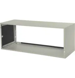
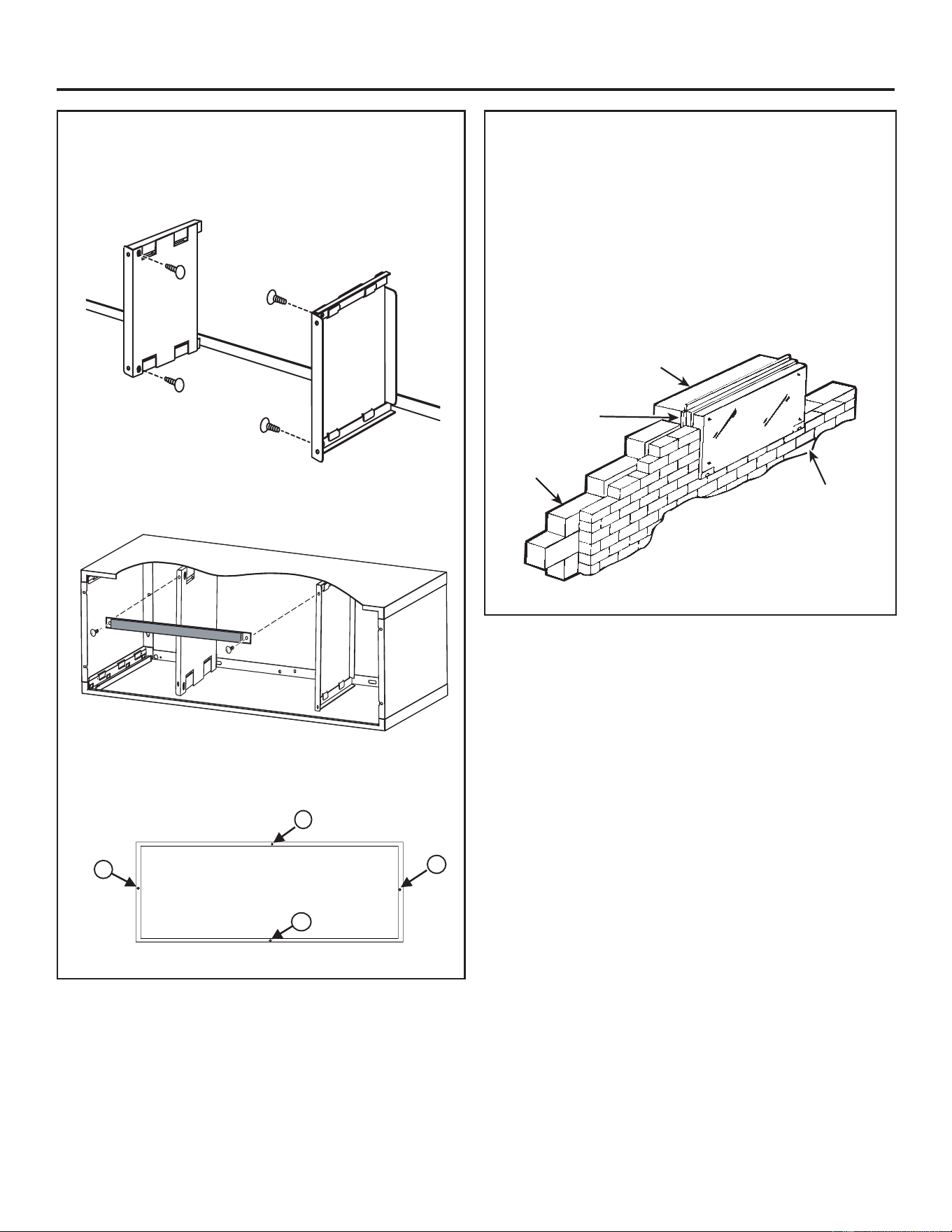
STEP 3:
Assemble the Wall Sleeve on Deep
Sleeve Models Only
:KHQDLUGLYHUWHUVDUHLQVHUWHGVHFXUHWKHPLQSODFHZLWKWKH
IRXUVXSSOLHGSXVKSLQV
6HFXUHXSSHUEUDFNHWZLWKIRDPJDVNHWWRWKHDLUGLYHUWHUV
XVLQJWKHWZRVXSSOLHGSXVKSLQV
,IUHTXLUHG/RFDWHZHDWKHUEDUULHUDQGDWWDFKWRWKHUHDURI
WKHDVVHPEOHGVOHHYHZLWKIRXUVXSSOLHGSXVKSLQV
Installation Instructions
STEP 4: Sleeve angles
,I¿HOGVXSSOLHGVOHHYHDQJOHVDUHWREHXVHGDQGPXVWEH
LQVWDOOHGSURFHHGDVIROORZV
1. Position the sleeve angle around top and sides of the sleeve
DWWKHGHVLUHGORFDWLRQIURQWWRUHDUZLWKDQJOHVIDFLQJ
WRZDUGUHDURXWVLGH
0DUNWKHVOHHYHWKURXJKWKHKROHVLQWKHVOHHYHDQJOHV
'ULOO´GLDPHWHUKROHVDWPDUNHGORFDWLRQVRQWKHVOHHYH
DQGDVVHPEOHWKHDQJOHVXVLQJRQO\[´VFUHZV,QVWDOO
the screws from the outside of the sleeve.
NOTE: Do not drill any holes in the bottom of the sleeve.
4
3
2
1
Weather Barrier
Rear View
Sleeve
Roomside
Block
Sleeve angle
¿HOGVXSSOLHG
Brick
4 31-5000912 Rev. 1
Installation Instructions
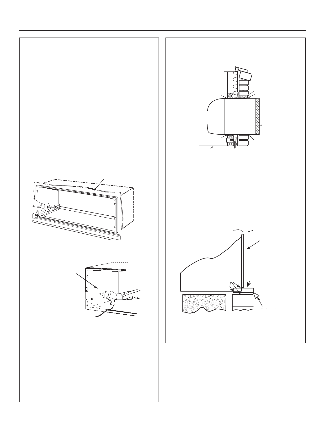
STEP 5: Installation of the sleeve in the
wall opening
1. Position the sleeve into the wall. Refer to chart on page
IRUURRPVLGHSURMHFWLRQ7KHUHDURXWVLGHHGJHRIWKH
VOHHYHVKRXOGH[WHQGDWOHDVW´EH\RQGWKHRXWVLGHZDOO
to be able to caulk properly and prevent sealing the drain
KROHVLQWKHUHDUÀDQJHRIWKHVOHHYH7KLVIDFLOLWDWHVHDV\
LQVWDOODWLRQRIDQDFFHVVRU\GUDLQLIGHVLUHG,ILWLVGHVLUHG
WRKDYHWKHUHDUJULOOHÀXVKRQWKHRXWVLGHDGULSUDLOPXVW
be installed under the sleeve and caulking applied between
WKHGULSUDLODQGVOHHYH6HHLQVWUXFWLRQVLQ6WHS
IMPORTANT:
Install sleeve level from side to side and from front to rear.
Using a level, allowable tilt to the outside is maximum of
1/4 bubble. Never allow sleeve to tilt to the inside.
If an internal drain kit is being installed, it is important to install
the sleeve level in all directions. Drain kits should be installed
before securing the sleeve to the wall.
Inside wall
)LUPO\VHFXUHWKHVOHHYHWRWKHZDOOVWUXFWXUH'RQRWGULOO
any holes in the bottom of the sleeve.
Secure sleeve through
side and/or top only
2” min. from
sleeve bottom
&DXONWKHHQWLUHRSHQLQJRQWKHRXWVLGHEHWZHHQWKHVOHHYH
DQGWKHEXLOGLQJH[WHULRU
4. Caulk the entire opening on the inside between the sleeve
and the building interior.
Use lintel, when required, to support brick and block above the
sleeve.
NOTE: Do not drill any holes in the sleeve for electrical
connections. See the Zoneline Air Conditioner Owner’s
Manual for instructions on how to connect the electrical supply.
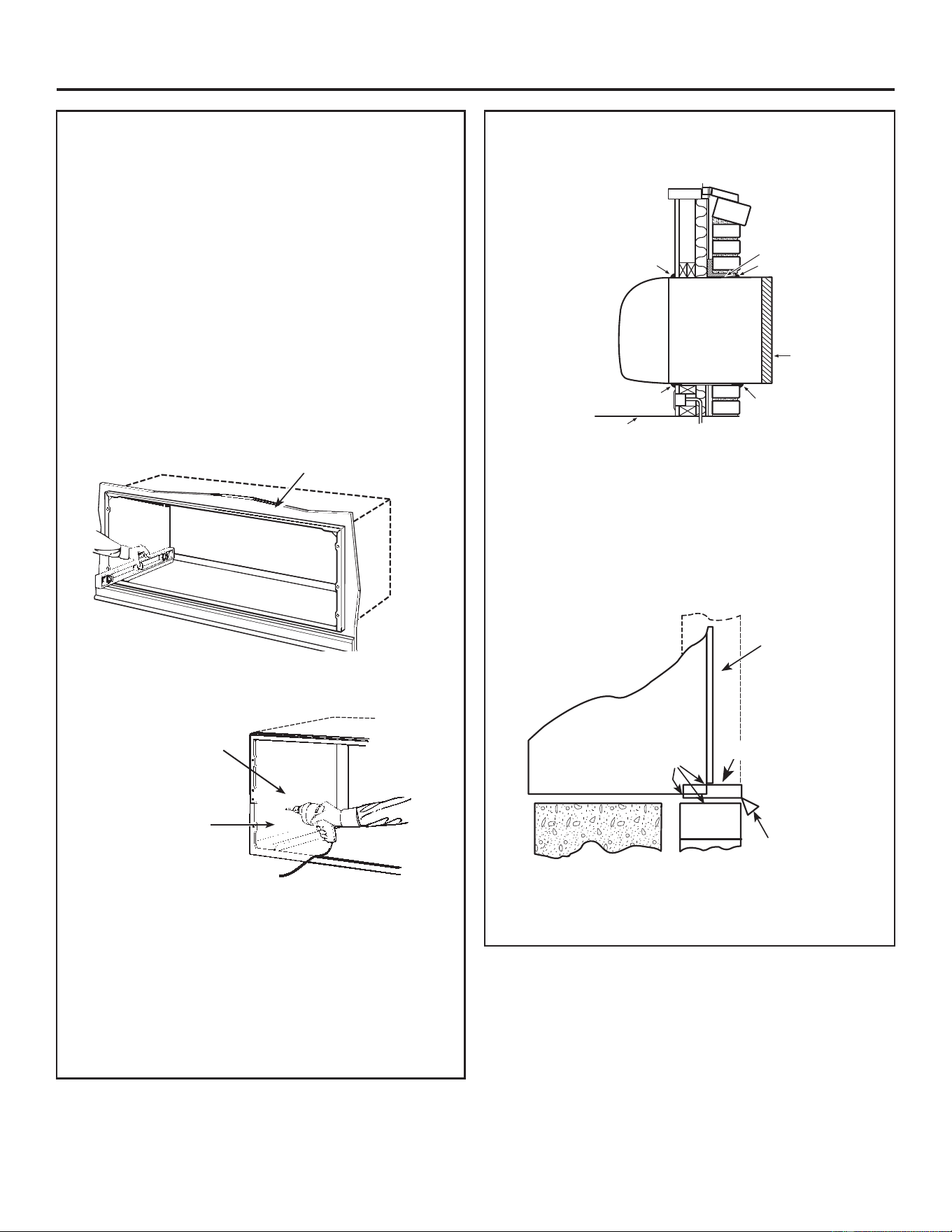
67(3:HDWKHUSURR¿QJ
:HDWKHUSURRIJDSVEHWZHHQWKHH[WHULRUDQGLQWHULRUZDOOVDQG
WKHVOHHYHZLWKFDXONLQJRUHTXLYDOHWZHDWKHUSURR¿QJPDWHULDO
Caulk*
Steel lintel
Caulk*
Outdoor
grille
Room
cabinet
Caulk*
Sleeve
Caulk*
FinisheGÀoor or top of carpet
NOTE:
*It is critical to caulk around the perimeter of the wall
sleeve on all four sides on the outside and roomside where
LWMRLQVWKHEXLOGLQJWRSUHYHQWDLUDQGZDWHULQ¿OWUDWLRQ
FOR INSTALLATION IN EXTRA THICK WALLS
1. If the sleeve is being installed in a wall where the recess is
´RUOHVVÀDVKLQJPXVWEHLQVWDOOHGXQGHUWKHVOHHYHDQG
H[WHQGXSWR´RQHDFKVLGH7KHÀDVKLQJPXVWLQFOXGHD
GULSUDLODVLOOXVWUDWHGLQWKH¿JXUHEHORZ
Outdoor
grille
Drip rail
Sleeve
Caulk**
Flashing
NOTE: **It is critical to caulk around the perimeter of the
ÀDVKLQJDQGGULSUDLOZKHUHLWMRLQVWKHEXLOGLQJDQGVOHHYHWR
SUHYHQWDLUDQGZDWHULQ¿OWUDWLRQ
31-5000912 Rev. 1
Installation Instructions
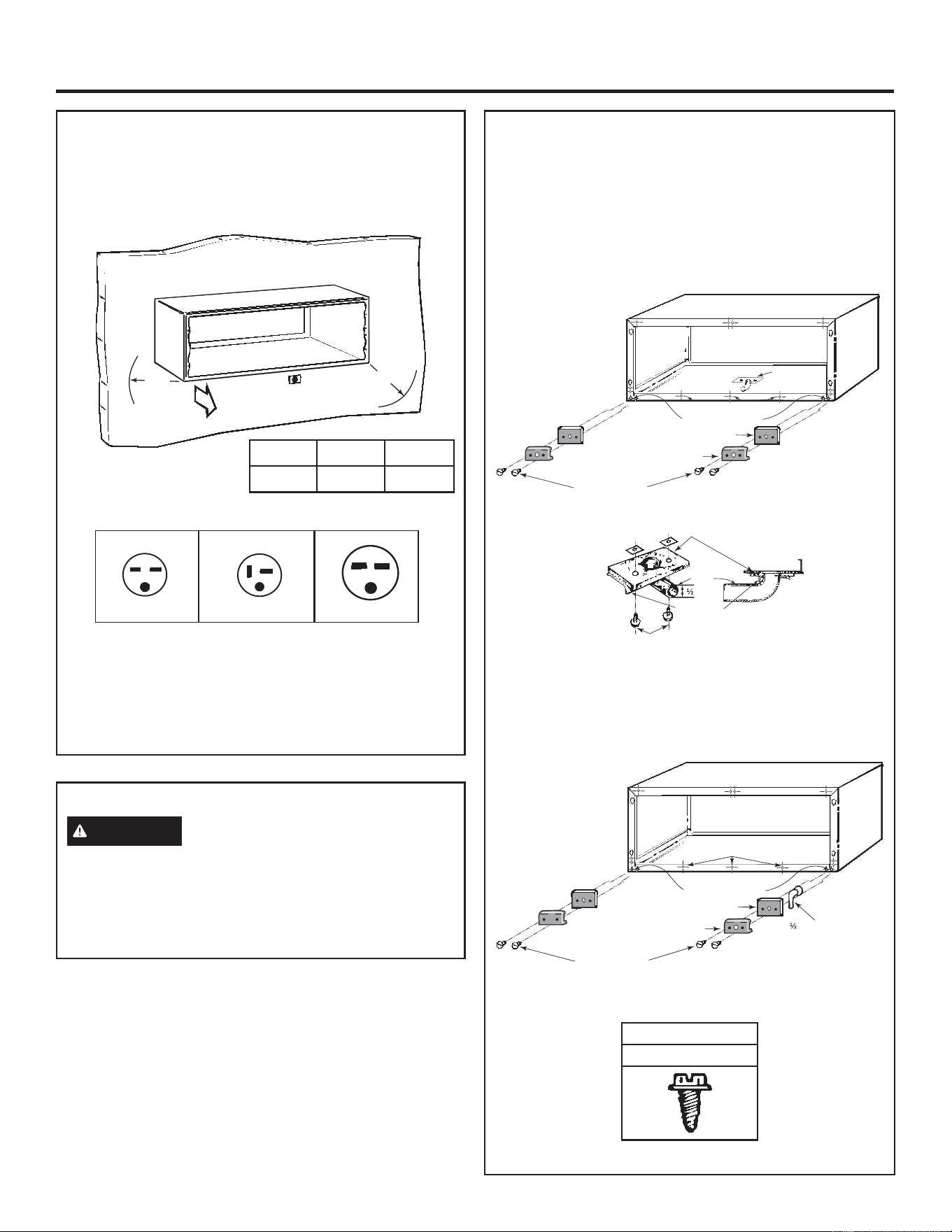
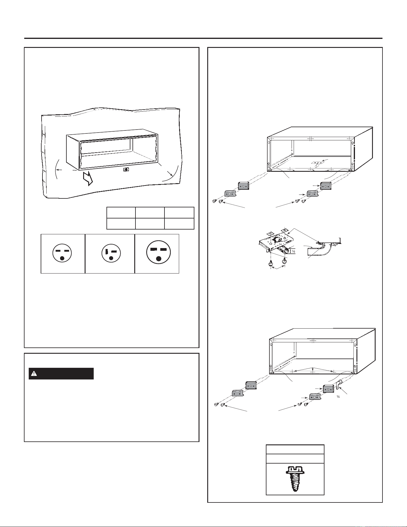
Electrical Requirements (230V/208V)
Provisions should be made to have the proper electrical outlet
near the sleeve. All wiring should be made in accordance with
local codes and regulations. The line cord included with the
FKDVVLVLIXVHGZLOOH[WHQGWRDZDOOUHFHSWDFOHORFDWHGZLWKLQ
the area shown in tabulation below.
Inside
“F”
“G”
Wall Receptacles
“tandem” type “perpendicular” type large “tandem” type
230V/208V 15 amp 230V/208V 20 amp 230V/208V 30 amp
NEMA6-15R
NEMA6-20R NEMA6-30R
All wiring should be made in accordance with local electrical
codes and regulation.
See the Owner’s Manual for how to connect electrical supply.
NOTE: Aluminum wiring in structure may pose special
SUREOHPV±FRQVXOWDTXDOL¿HGHOHFWULFLDQ
Drain Kit
If it is necessary to install a drain kit on this wall sleeve, the
IROORZLQJNLWLVDYDLODEOH
RAD10 Internal/External Drain
:LWKDQ³,QWHUQDO'UDLQ´WKHFRQGHQVDWHGUDLQWXEHPXVWEH
connected to an internal drain system in the building.
Wall Sleeve with RAD10 Drain Unit
Internal Drain
Note: S haded part s
includ ed w it h
RAD10 dr ain ki t
See detail
below
2YHUÀRZUHOLHIGUDLQ
Square drain holes
Neoprene sponge gasket
Steel mounting plate
Type “A” screws
Speed nuts
Gasket
Cabinet bottom
Tube
” O.D.
Steel mounting plate
Type “A” screws
:LWKDQ³([WHUQDO'UDLQ´ZKLFKPD\EHFRQQHFWHGWRD¿HOG
VXSSOLHGGUDLQOLQHFRQGHQVDWHZDWHUFDQEHGUDLQHGDZD\
from the unit and building.
Wall Sleeve with RAD10 Drain Unit
External Drain
2YHUÀRZUHOLHIGUDLQ
6TXDUHGUDLQKROHV
1HRSUHQHVSRQJHJDVNHW
6WHHOPRXQWLQJSODWH
7\SH³$´VFUHZV
´2'GUDLQWXEH
NOTE: It may be desirable or necessary to install the drain kit
on the sleeve prior to installing the sleeve into the wall.
Screw
7\SH³$´0HWDO
Electrical Requirements (265V)
WARNING
&RQQHFWLRQRID9SURGXFWWRDEUDQFKFLUFXLWMUST
be done by direct connection to be in compliance with the
1DWLRQDO(OHFWULF&RGH3OXJJLQJD9XQLWGLUHFWO\LQWRD
EXLOGLQJPRXQWHGH[SRVHGUHFHSWDFOHLVQRWSHUPLWWHGE\FRGH
See the Owner’s Manual for how to connect the electrical supply.
Model ³)´ ³*´
AZ Series ´PD[ ´PD[
6SHFL¿FDWLRQVVXEMHFWWRFKDQJHZLWKRXWQRWLFH
NOTE: Shaded parts
included with RAD10
drain Kit.
NOTE: Shaded parts
included with RAD10
drain Kit.

6 31-5000912 Rev. 1
Notes
7
31-5000912 Rev. 1 06-25
Instructions d’installation pour le
nouveau
RAB42*
Assemblage requis
Manchon mural pour toute la
série AZ Modèles Zoneline
Avant de commencer - Veuillez lire ces instructions
attentivement et en totalité. IMPORTANT – OBSERVEZ
TOUS LES CODES ET RÈGLEMENTS EN VIGUEUR.
Note à l’installateur – Assurez-vous de laisser ces
instructions au consommateur. Note au consommateur
- Conservez ces instructions avec votre manuel
d’utilisation pour consultation ultérieure.
REMARQUES :
• Manipulez le manchon avec soin.
• Le raidisseur en carton à l’intérieur de la gaine ainsi que le
panneau de protection arrière doivent demeurer en place
jusqu’à ce que le châssis soit installé afin d’assurer la rigidité
et la perpendicularité de la gaine.
• Si un socle est utilisé, il pourrait être souhaitable de
l’assembler au manchon avant de fixer ce dernier au mur.
DIMENSIONS CRITIQUES
Ceiling
“A”
“B”
“C”
Roomside
Outside
wall
“D”
)LQLVKHGÀRRURUWRSRIFDUSHW
REMARQUE :
Une attention particulière doit être portée à l’emplacement de
O¶HQWUpHpOHFWULTXHSDUUDSSRUWjODJDLQHPXUDOHD¿QG¶DVVXUHU
l’accès à l’alimentation une fois l’appareil installé.
Dimensions Dégagements d’installation recommandés
A +DXWGXPDQFKRQMXVTX¶DXSODIRQG¿QL±SRPLQ
B 6DLOOLHGXPDQFKRQGDQVODSLqFHjSDUWLUGXPXU¿QL
óSRPLQDXFXQVRFOHǪSRPLQORUVTX¶XQVRFOH
est utilisé. Si plus de 6 po du manchon fait saillie
dans la pièce, un socle ou un autre type de support
est recommandé
C Saillie du manchon à l’extérieur - ¼ po min.
D +DXWHXUDXGHVVXVGXSODQFKHU¿QLRXGXGHVVXV
de tapis - 0 po min. sans socle, 3 po min./5 po max.
avec socle.
E Côté gauche/droit du manchon par rapport au mur
DGMDFHQW±SRPLQ
REMARQUE : Pour les manchons avec vidange interne,
mettez de niveau dans toutes les directions. Pour les
manchons avec vidange externe, mettez de niveau de gauche
à droite avec une légère inclinaison vers l’extérieur pour la
vidange (inclinaison maximale : 1/4 de bulle vers l’extérieur).
EMPLACEMENT DU MANCHON
Pour fonctionner correctement, le manchon doit se trouver sur
un mur extérieur. En règle générale, le climatiseur être centré
dans un mur extérieur pour assurer une distribution d’air
climatisé correcte. Cette section de mur doit être dépourvue
de câblage électrique, de plomberie et d’obstructions
immédiatement à l’intérieur ou l’extérieur.
Pour de l’information détaillée, veuillez vous reporter au manuel des données de conception des ingénieurs et architectes GE relatif
aux climatiseurs Zoneline. Pour obtenir une copie de ce manuel, appelez le GE Appliances au 800.626.2000 ou visitez-nous sur
Zoneline.com.
Outside wall
“E”
“E”
Top of Sleeve
Haut du manchon
Mur extérieur
Côté pièce
Techo
Mur extérieur
3ODQFKHU¿QLRXGHVVXVGHWDSLV
8 31-5000912 Rev. 1
ÉTAPE 1: Préparation du mur
Le manchon mural doit être installé pendant la construction
et des linteaux doivent être utilisés pour supporter le bloc
au-dessus du manchon mural. Le manchon ne soutiendra
pas le bloc de béton ou la brique. La hauteur et la largeur du
manchon sont modulaires :
Hauteur — S’insère dans 2 rangées de blocs de béton.
— S’insère dans 6 rangées de briques standard.
— S’insère dans 5 rangées de briques grand format.
Largeur — S’insère dans 3 espaces de montant environ.
Il faut pratiquer des ouvertures dans le cas d’une construction
existante. Il est essentiel de pratiquer des ouvertures aux
dimensions appropriées pour éviter l’utilisation de fourrures ou
de bâti additionnel.
42
1
/
2
16
1
/4
16¼” Min.
42 ¼” Min.
“D”*
REMARQUE : Utilisez un linteau pour soutenir une brique, un
bloc, etc., au-dessus du manchon de climatiseur. (Il n’est pas
nécessaire d’utiliser un linteau immédiatement sous un seuil
de fenêtre.)
ÉTAPE 2 : Assembler le manchon mural
1. Placez le panneau inférieur sur une surface propre, plane et
de niveau.
2. Repérez le panneau latéral gauche. Alignez le panneau
sur la fente du
panneau inférieur
gauche. Insérez le
panneau gauche
dans le panneau
inférieur jusqu’à ce
que les languettes
se verrouillent
complètement.
3. Repérez le panneau
latéral droit. Alignez
le panneau sur la
fente du panneau
inférieur droit. Insérez
le panneau droit
dans le panneau
inférieur jusqu’à ce
que les languettes
se verrouillent
complètement.
4. Repérez le panneau
supérieur et alignez-le
sur le dessus des panneaux latéraux gauche et droit. Insérez
le panneau supérieur dans les panneaux latéraux gauche et
droit jusqu’à ce que les languettes se verrouillent.
Front View
Front View
Front View
Front View
Instructions d’installation
Montant principal
Montants nains
Montants
nains
Linteau - 4 x 4 po ou
deux 2 x 4 po sur le chant
Ajuster le
bâti pour
obtenir ces
dimensions
(*Voir le
tableau de la
page 1)
Sole
Dimensions Minimales De L’ouverture Finie*
Hauteur Largeur
16 1/4”
42 1/4”
* Une situation particulière comme l’utilisation de cornières de gaine
peut nécessiter d’augmenter les dimensions.
Dimensions de manchon
Hauteur Largeur
16” 42”
Profondeur
RAB42MG ເ»´
RAB4216MG 16”
RAB4218MG 18”
RAB4220MG 20”
RAB4224MG 24”
ÉTAPE 3: Assemblez le manchon mural
sur les modèles à manchon
profond seulement
$OLJQH]OHVSDQQHDX[GXGpÀHFWHXUG¶DLUDYHFOHVODQJXHWWHV
(sur modèles à manchon profond) situées sur les panneaux
supérieur et inférieur. Faites-les glisser jusqu’à ce que les
trous de la surface verticale soient alignés. Les numéros
de modèle avec manchon allongé sont les suivants :
RAB4216MG, RAB4218MG, RAB4220MG, RAB4224MG.
RIGHT
SIDE
PANEL
Alignez ces trous
Assurez-vous que le panneau
s’engage avec la languette
sur les panneaux inférieur et
supérieur correctement
Vue de face
Vue de face
Vue de face
Vue de face
931-5000912 Rev. 1
Instructions d’installation
ÉTAPE 4 : (facultatif) Cornières de gaine
S’il faut installer des cornières de gaine (achetées localement),
procédez comme suit :
1. Positionnez l’angle de manchon autour du haut et des côtés
du manchon à l’emplacement souhaité (d’avant en arrière)
avec les angles faisant face vers l’arrière (extérieur).
2. Marquez le manchon à travers les trous dans les angles de
manchon.
3. Percez des trous de 5/32 po de diamètre aux emplace-
ments marqués dans le manchon et assemblez les angles
en utilisant uniquement des vis #10x1/2 po. Installez les vis
depuis l’extérieur du manchon
REMARQUE : Ne percez aucun trou dans la base du manchon.
ÉTAPE 3 :
Assemblez le manchon mural sur
les modèles à manchon profond
seulement
2. Lorsque des dispositifs de répartition d’air sont insérés,
¿[H]OHVVROLGHPHQWHQSODFHjO¶DLGHGHVTXDWUH
goupilles-poussoir fournies.
3. Fixez le support supérieur (avec un joint d’étanchéité en
mousse) sur les dispositifs de répartition d’air à l’aide des
deux (2) goupilles-poussoir fournies.
$XEHVRLQ5HSpUH]ODEDUULqUHLJQLIXJHHW¿[H]ODjO¶DUULqUH
du manchon assemblé à l’aide des quatre (4) goupilles-
poussoir fournies.
Manchon
Côté pièce
Bloc
Angle de
manchon (acheté
localement)
Brique
4
3
2
1
Weather Barrier
Rear View
Vue arrière
Panneau anti-
intempéries
10 31-5000912 Rev. 1
ÉTAPE 6: Étanchéisation
Étanchéisez les espaces entre les murs extérieur
et intérieur et le manchon avec un produit
d’étanchéité ou un matériel hydrofuge équivalent.
Caulk*
Steel lintel
Caulk*
Outdoor
grille
Room
cabinet
Caulk*
Sleeve
Caulk*
FinisheGÀoor or top of carpet
REMARQUE: *Il est essentiel de calfeutrer le périmètre
du manchon mural des quatre côtés sur l’extérieur et le
côté pièce à l’endroit où il rejoint le bâtiment pour éviter
O¶LQ¿OWUDWLRQG¶DLUHWG¶HDX
Installation dans des murs très épais
1. Si le manchon est installé dans un mur où le renfoncement
est de 3 po ou moins, un solin doit être installé sous le
manchon et s’étendre jusqu’à 2 po de chaque côté. Le solin
GRLWFRPSUHQGUHXQHJRXWWLqUHFRPPHLOOXVWUpGDQVOD¿JXUH
ci-dessous.
Outdoor
grille
Drip rail
Sleeve
Caulk**
Flashing
REMARQUE: **Il est essentiel de calfeutrer les périmètres du
solin et de la gouttière là où ils joignent le bâtiment et la gaine
D¿QGHSUpYHQLUOHVLQ¿OWUDWLRQVG¶DLUHWG¶HDX
Instructions d’installation
ÉTAPE 5 : Installation du manchon dans
l’ouverture murale
1. Placez le manchon dans le mur. Consultez le tableau de la
page 1 pour connaître la saillie côté pièce. Le bord arrière
(extérieur) du manchon doit faire saillie d’au moins ¼ po
au-delà du mur extérieur pour qu’il soit possible de calfeu-
trer correctement. De plus, il faut éviter de sceller les trous
de vidange dans la bride arrière du manchon. Au besoin,
ceci facilite l’installation. (Si vous souhaitez avoir une grille
DUULqUHHQDႉHXUHPHQWVXUO¶H[WpULHXULOIDXWLQVWDOOHUXQH
gouttière sous le manchon et calfeutrer entre la gouttière et
le manchon.) Consultez les instructions de l’étape 6.
IMPORTANT:
Installez le manchon au niveau d’un côté à l’autre et de
l’avant à l’arrière. En utilisant un niveau, l’inclinaison
admissible vers l’extérieur est d’au maximum 1/4 de bulle.
Ne laissez jamais le manchon s’incliner vers l’intérieur.
Si une trousse de vidange interne est installée, il est important
d’installer le manchon au niveau dans toutes les directions.
/HVWURXVVHVGHYLGDQJHGRLYHQWrWUHLQVWDOOpHVDYDQWGH¿[HU
le manchon au mur.
Inside wall
2. Fixez fermement le manchon à la structure murale. Ne
percez aucun trou dans la base du manchon.
Secure sleeve through
side and/or top only
2” min. from
sleeve bottom
3. Calfeutrez l’ouverture en entier à l’extérieur entre le
manchon et l’extérieur du bâtiment.
4. Calfeutrez l’ouverture en entier sur l’intérieur, entre le
manchon et l’intérieur du bâtiment.
Utilisez un linteau, au besoin, pour soutenir la brique et le bloc
au-dessus du manchon.
REMARQUE : ne percez aucun trou dans le manchon
pour des connexions électriques. Consultez le manuel
du propriétaire du climatiseur Zoneline pour obtenir
OHVLQVWUXFWLRQVVXUODPDQLqUHG¶HႇHFWXHUOHUDFFRUGj
l’alimentation électrique.
Mur intérieur
Fixez le manchon dans
le côté et/ou le dessus
seulement
2 po min.
depuis le bas
du manchon
Calfeutrage*
Calfeutrage*
Calfeutrage*
Solin
Gouttière
Calfeutrage*
Linteau en acier
Grille
extérieure
Carrosserie
côté pièce
Manchon
3ODQFKHU¿QLRXGHVVXVGHWDSLV
Calfeutrage**
Grille
extérieure
Manchon
1131-5000912 Rev. 1
TROUSSE DE VIDANGE
S’il est nécessaire d’installer une gouttière sur le manchon
PXUDOODWURXVVHVXLYDQWHHVWRႇHUWH
Dispositif de vidange intérieur/extérieur RAD10
1. Avec un dispositif de vidange intérieur, le tube de vidange
du condensat doit être raccordé au système d’évacuation
intérieur du bâtiment.
Manchon mural avec unité de vidange RAD10
Vidange interne
Note: S haded part s
included w it h
RAD10 dr ain ki t
See detail
below
2YHUÀRZUHOLHIGUDLQ
Square drain holes
Neoprene sponge gasket
Steel mounting plate
Type “A” screws
Speed nuts
Gasket
Cabinet bottom
Tube
” O.D.
Steel mounting plate
Type “A” screws
2. Avec un dispositif de vidange extérieur (qu’on peut
raccorder à un tuyau de vidange acheté localement), l’eau
de condensation peut être évacuée à l’écart de l’appareil et
du bâtiment.
Manchon mural avec unité de vidange RAD10
Vidange externe
2YHUÀRZUHOLHIGUDLQ
6TXDUHGUDLQKROHV
1HRSUHQHVSRQJHJDVNHW
6WHHOPRXQWLQJSODWH
7\SH³$´VFUHZV
´2'GUDLQWXEH
REMARQUE: Il pourrait être souhaitable ou nécessaire
d’installer une trousse de vidange sur le manchon avant
d’installer le manchon dans le mur.
VIS
Type “A” MÉTAL
EXIGENCES ÉLECTRIQUES (230V/208V)
Des dispositions doivent être prises pour disposer d’une prise
électrique adéquate proche du manchon.Tout le câblage doit
rWUHHႇHFWXpFRQIRUPpPHQWDX[FRGHVHWUqJOHPHQWVORFDX[
Le cordon de ligne fourni avec le châssis (le cas échéant)
s’étend à une prise murale située dans la zone indiquée dans
le tableau ci-dessous.
Inside
“F”
“G”
Prises murales
“tandem” type “perpendicular” type large “tandem” type
230V/208V 15 amp 230V/208V 20 amp 230V/208V 30 amp
NEMA6-15R
NEMA6-20R NEMA6-30R
Tout le câblage électrique doit être réalisé conformément aux
codes et règlements locaux.
Consultez le manuel d’utilisation pour savoir comment
raccorder l’alimentation électrique.
REMARQUE: Le câblage en aluminium dans la structure peut
poser des problèmes particuliers, consultez un électricien
TXDOL¿p
EXIGENCES ÉLECTRIQUES (265 V)
AVERTISSEMENT
Le raccordement d’un produit alimenté par un courant de 265
V à un circuit de dérivation DOIT être réalisé par raccordement
GLUHFWD¿QG¶rWUHFRQIRUPHDX&RGHQDWLRQDOGHO¶pOHFWULFLWp
Ce code interdit le branchement d’un appareil de 265 V
directement dans une prise murale exposée.
Consultez le manuel d’utilisation pour savoir comment
raccorder l’alimentation électrique.
Modèle “F” “G”
Série AZ 21” max. 58” max.
6RXVUpVHUYHGHPRGL¿FDWLRQVVDQVSUpDYLV
Instructions d’installation
Remarque : Les
parties ombragées
sont incluses avec la
trousse de vidange
RAD10.
Remarque : Les
parties ombragées
sont incluses avec la
trousse de vidange
RAD10.
Intérieur
Bas de gaine
Joint
d’étanchéité
Tube
Plaque de montage
en acier
Plaque de montage en acier
2UL¿FHVG¶pFRXOHPHQWFDUUpV
Joint néoprène
Vis de type « A »
Vis de type « A »
Écrous à
ressort
2UL¿FHVGHWURSSOHLQ
Voir détails
ci-dessous
Plaque de montage
en acier
2UL¿FHVG¶pFRXOHPHQW
carrés
Joint néoprène
Vis de type « A »
2UL¿FHVGHWURSSOHLQ
Tube de vidange
1/2 po D.E.

12 31-5000912 Rev. 1
Remarques