JAN24V1
OWNER’S GUIDE
serial number:
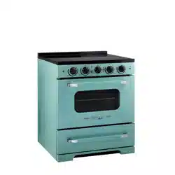
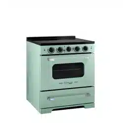
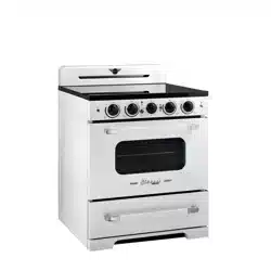
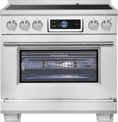
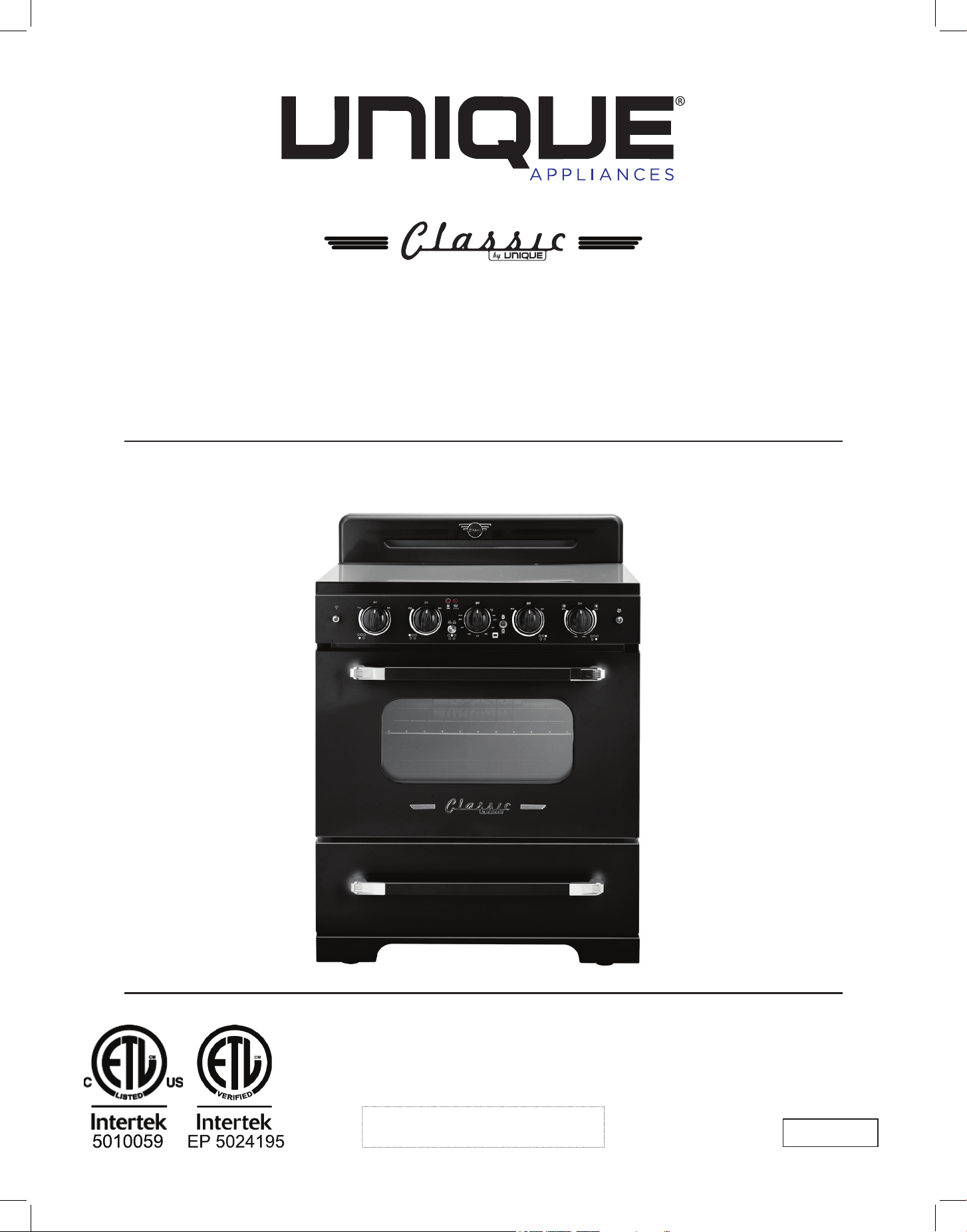
CLASSIC RETRO BY UNIQUE
30" INDUCTION RANGE
30” (76.2 cm)
MODEL NUMBER: UNQ-30CR IC W, UNQ-30CR IC B, UNQ-30CR IC LG, UNQ-30CR IC T
2
Read and save these instructions
Installation & Owner’s Manual
This manual contains information for:
• Important Safeguards
• Installation
• Use and Care
IMPORTANT
TO THE OWNER OF THE RANGE: Retain this owner’s manual for future reference.
TO THE INSTALLER: Leave this owner’s manual with the range.
Certain ranges come equipped with special features. Determine from a study of your
range which of the instructions given in this booklet pertain to your range.
This booklet gives valuable instructions covering the installation, adjustment and use of
your range.
How to Obtain Service and/or Parts
If your range does not operate in accordance with the instructions in the manual, you
should contact the dealer in your immediate vicinity for service. Or, the purchaser may
contact the service organization noted on the warranty.
CLASSIC RETRO 30" (76.2 CM) INDUCTION RANGE
3
MANUFACTURED & CERTIFIED BY
Unique Appliances Ltd
2245 Wyecroft Road #5, Oakville, Ontario, Canada L6L 5L7
www.UniqueAppliances.com
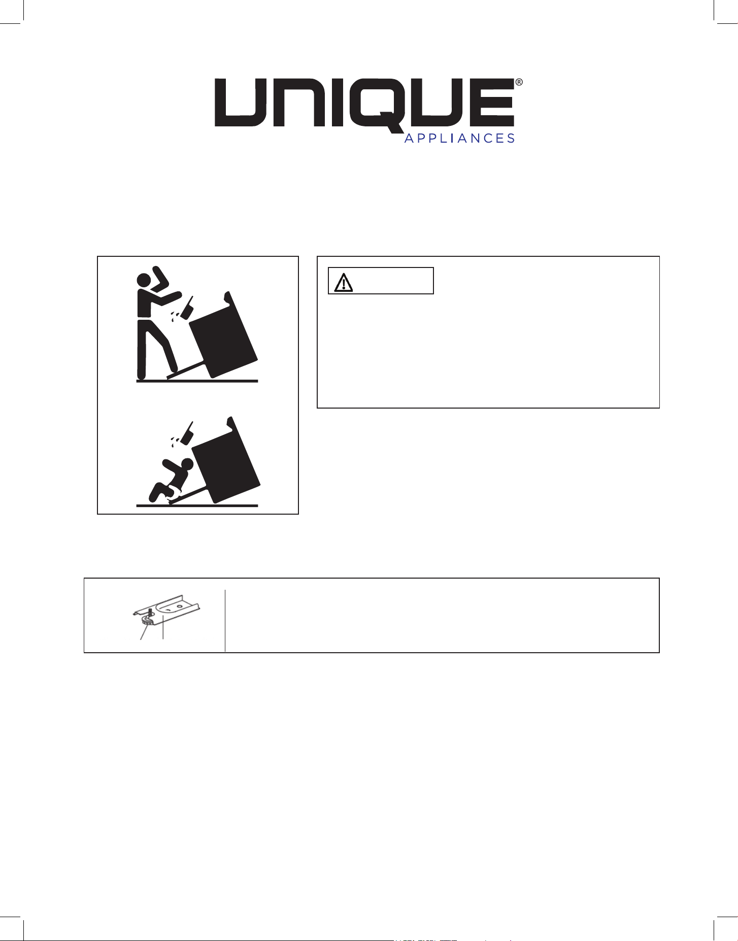
WARNING
To reduce the risk of tipping the
appliance by abnormal usage or improper door
loading, the appliance must be secured by properly
installing the Anti-Tip device packed with the
appliance. To check if the device is installed and
engaged properly, carefully tip the range forward.
The Anti-Tip device should engage and prevent the
range from tipping over.
If this range is removed for any reason, service or
cleaning, etc., it must be replaced as outlined in the
installation instructions before placing the range back
in operation.
Making sure the anti-tip bracket is installed:
• Slide range forward.
• Look for the anti-tip bracket securely attached to fl oor.
• Slide range back so rear range foot is under anti-tip bracket.
X2
Range Foot Anti-tip Bracket

4
IMPORTANT SAFETY NOTES . . . . . . . . . . . . . . . . . . . . . . . . . . . 6
BEFORE INSTALLING YOUR RANGE . . . . . . . . . . . . . . . . . . . . . . . 10
GROUNDING INSTRUCTIONS . . . . . . . . . . . . . . . . . . . . . . . . . . . 11
HOW TO INSTALL THE BACKSPLASH . . . . . . . . . . . . . . . . . . . . . . . 11
HOW TO INSTALL CONTROL KNOBS . . . . . . . . . . . . . . . . . . . . . . . 12
ANTI-TIP BRACKET INSTALLATION . . . . . . . . . . . . . . . . . . . . . . . . 13
WALL CLEARANCES & ANTI-TIP LOCATION . . . . . . . . . . . . . . . . . . . 14
PARTS & FEATURES . . . . . . . . . . . . . . . . . . . . . . . . . . . . . . . . . 17
GETTING TO KNOW YOUR INDUCTION RANGE . . . . . . . . . . . . . . . . . 18
RANGE CONTROLS . . . . . . . . . . . . . . . . . . . . . . . . . . . . . . . . 20
OPERATION OF RANGE . . . . . . . . . . . . . . . . . . . . . . . . . . . . . 22
OPERATION OF OVEN . . . . . . . . . . . . . . . . . . . . . . . . . . . . . . 24
CARE & MAINTENANCE. . . . . . . . . . . . . . . . . . . . . . . . . . . . . . 26
CLEANING THE RANGE . . . . . . . . . . . . . . . . . . . . . . . . . . . . . 29
TROUBLESHOOTING . . . . . . . . . . . . . . . . . . . . . . . . . . . . . . . . 29
ERROR CODES . . . . . . . . . . . . . . . . . . . . . . . . . . . . . . . . . . . . 31
WIRING DIAGRAM . . . . . . . . . . . . . . . . . . . . . . . . . . . . . . . . . 32
RATING LABEL . . . . . . . . . . . . . . . . . . . . . . . . . . . . . . . . . . . 33
WARRANTY. . . . . . . . . . . . . . . . . . . . . . . . . . . . . . . . . . . . . 34
APPLIANCE INFORMATION. . . . . . . . . . . . . . . . . . . . . . . . . . . . 35
PRODUCT REGISTRATION . . . . . . . . . . . . . . . . . . . . . . . . . . . . 35
CONTACT US . . . . . . . . . . . . . . . . . . . . . . . . . . . . . . . . . . . . 35
TABLE OF CONTENTS

5
Congratulations on your purchase of a UNIQUE range! We are very proud of our product –
and are committed to providing you with the best service possible. Your satisfaction is our
#1 priority. Please read this manual very carefully. It contains valuable information on how to
properly maintain your new Unique induction range.
We know you will enjoy your new range and thank you for choosing one of our Unique
Appliances! We hope you will consider us for future purchases.
PLEASE READ AND SAVE THESE INSTRUCTIONS
This manual provides specific operation instructions for your model. Use your range only as
instructed in this manual. These instructions are not meant to cover every possible condition
and situation that may occur. Common sense and caution must be practiced when installing,
operating and maintaining the appliance.
Record in the space provided below the Model No. and Serial No. of this appliance.
These numbers are found on the serial plate located at the bottom drawer.
Model No. ______________________
Serial No. ________________________
Purchase Date ________________________
Record these numbers for future use.
IMPORTANT: Keep a copy of your bill of sale. The date on the bill establishes the warranty
period should service be required. If service is performed, it is in your best interest to obtain
and keep all receipts.
Right now:
Please visit our website at https://UniqueAppliances.com/product-registration/ to register
your product.
WELCOME
NEED HELP?
6
USER SERVICING: Do not repair or replace any part of the appliance unless specifically
recommended in this owner’s guide. Only a qualified technician should do all other servicing.
This will reduce the risk of personal injury and damage to the range.
Storage in or on appliance: Flammable materials should not be stored in an oven, near
surface elements or in the broiler section. This includes paper, plastic and cloth items, such
as cookbooks, plastic ware and towels, as well as flammable liquids. Do not use the oven for
storage. Do not store explosives, such as aerosol cans, on or near the range.
Remove the oven door from any unused range if it is to be stored or discarded.
Stepping, leaning or sitting on the doors or broiler section of this range can result in serious
injuries and cause damage to the range.
The following situations could cause bodily injury or property damage:
DO NOT TOUCH INTERIOR SURFACES OF THE OVEN. Oven elements may be hot even
though o. When in use, and after cooking cook ware may become hot enough to cause burns.
During and after use, do not touch, or let clothing or other flammable materials touch cook
ware, oven vent openings, oven door and windows, and adjacent surfaces until they have had
sucient time to cool.
NEVER use this appliance as a space heater to heat or warm the room.
Wear proper apparel. Loose fitting or hanging garments should never be worn while using
the appliance. Do not let clothing or other flammable materials contact cook ware or interior
surfaces of the oven until they have had sucient time to cool.
Never modify or alter the construction of the range. Do not remove leveling legs, panels, wire
covers, anti-tip brackets or any other permanent part of the product.
When heating fat or grease, watch it closely. Fat or grease may catch fire if allowed to become
too hot.
Do not use water or our on grease res. Smother the fire with a pan lid, baking soda or use
a dry chemical or foam-type extinguisher.
Use only dry potholders. Wet or damp potholders on hot surfaces could result in burns from
steam. Do not let the potholder touch heating areas. Do not use a towel or other bulky cloth
instead of a potholder.
NEVER cover any slots, holes or passages in the oven bottom or cover an entire
rack with materials such as aluminum foil. Doing so blocks air flow through the oven and
may cause carbon monoxide poisoning. Aluminum foil linings may also trap heat, causing a
fire hazard. Refer to the cleaning section of this manual for more information on the use of
aluminum foil.
IMPORTANT SAFETY NOTES
7
WARNINGS
Destroy and recycled the carton and plastic bags after the range is unpacked. Children should
not use packaging material for play. Cartons covered with rugs, bedspreads, or plastic sheets can
become airtight chambers that can trap a child. Remove all staples from the carton. Staples can
cause severe cuts and destroy finishes if they come in contact with other appliances or furniture.
Be safety conscious. The preparation of food on a range and in an oven requires
temperatures that could cause severe burns. Before using this new appliance, carefully read
and follow all instructions.
WARNING
PROP 65 WARNING FOR CALIFORNIA RESIDENTS
The California Safe Drinking Water and Toxic Enforcement Act of 1986 (Proposition 65)
requires the Governor of California to publish a list of substances known to the State of
California to cause cancer or reproductive harm. In addition, businesses must warn customers
of potential exposure to such substances
The following situations may cause serious bodily harm, death or property damage:
TO REDUCE THE RISK OF TIPPING OF THE RANGE, THE RANGE MUST BE SECURED BY A
PROPERLY INSTALLED ANTI-TIP BRACKET PROVIDED WITH THE RANGE. TO CHECK IF THE
DEVICE IS INSTALLED AND ENGAGED PROPERLY, CAREFULLY TIP THE RANGE FORWARD.
THE ANTI-TIP DEVICE SHOULD ENGAGE AND PREVENT THE RANGE FROM TIPPING OVER.
REFER TO THE INSTALLATION INSTRUCTIONS PACKAGED WITH THE ANTI-TIP BRACKET
FOR PROPER ANTI-TIP BRACKET INSTALLATION. See page 14 for details.
• Never leave children alone or unattended in the area where an appliance is in use. They
should never be allowed to sit or stand on any part of the appliance. Never leave the oven
door open when the range is unattended.
• Do not store items of interest to children in the cabinets above a range or on the
backguard of a range. Children climbing on the range to reach the items could be seriously
injured.
• Do not allow children to climb or play around the range. The weight of a child on an open
oven door may cause the range to tip, resulting in serious burns or other injury.
IMPORTANT: Observe all governing codes and ordinances. Do not obstruct flow of heat and
ventilation.
IMPORTANT SAFETY NOTES

8
Placement of oven racks: Always place an oven rack in the desired location while the oven is
cool. If a rack must be moved when the oven is hot, use potholders and grasp the rack with
both hands to reposition. Do not let potholders contact hot oven walls. Remove all cookware
from the rack before moving.
Do not heat unopened food containers. Build-up of pressure may cause the container to
burst and result in injury.
Keep the oven vent duct unobstructed. The oven vent is located along the bottom of the
back guard. Touching the surfaces in the vent area when the oven is being operated may
cause severe burns. Also, do not place plastic or heat-sensitive items on or near the oven
vents. These items could melt or ignite. The range requires adequate ventilation for heat
dissipation. Do not block the flow of air around the base or beneath the lower front panel of
the range.
Use care when opening oven door: Stand to the side of the oven when opening the oven
door. Slowly open the door to allow hot air or steam to escape before removing or replacing
food.
Know which knob controls each element. Place a pan of food on the element before turning
it on, and turn the element o before removing the pan.
Cookware handles should be turned inward and not extend over adjacent surface
elements as to reduce the risk of burns, ignition of flammable materials, and spillage due to
unintentional contact with the cookware.
Never leave the surface elements unattended. Boil-overs, grease and spills may catch fire,
and a pan which has boiled dry may melt.
Do not place hands between the spring tension hinge and the oven door frame when you
are removing the oven door. You could pinch your fingers.
Be care when touching or removing pots and pans from the range, as they will be hot. Even
after the surface element has been turned o, the pot/pan is hot enough to cause burns.
When removing appliance for cleaning and/or service:
• Disconnect AC power supply.
• Carefully remove the range by pulling outward.
CAUTION: Range is heavy. Use care in handling.
NOTE: When installing or removing the range for service, a rolling lift jack should be used.
Do not push against any of the edges of the range in an attempt to slide it into or out of
the installation. Pushing or pulling a range (rather than using a lift jack) also increases the
possibility of bending the leg spindles or damaging the internal coupling connectors.
Never clean appliance parts with ammable uids. These fumes can create a fire hazard
or explosion. And do not store or use gasoline or other flammable vapors and liquids in the
vicinity of this or any other appliance. The fumes can create a fire hazard or explosion.
IMPORTANT SAFETY NOTES
9
Before proceeding with cleaning and maintenance operations, make sure the power line of
the unit is disconnected.
Do not attempt to repair or replace any part of your appliance unless it is specifically
recommended in this manual. All other servicing should be done by a qualified technician.
Clean the range regularly. Exhaust fan ventilating hoods and grease filters should be kept
clean. Do not allow fat or grease to accumulate. Greasy deposits in the fan could catch fire.
Refer to the hood manufacturer’s instructions for cleaning.
Use Induction-ready cookware: Only cast iron, enamelled cast iron, some stainless steel and
induction-ready cookware can be used with an induction range. Check the manufacturer’s
recommendations for rangetop use, and consult page 17 for more information.
Do not use a wok equipped with a metal ring. Only flat bottomed woks are suitable.
Use proper pan size: This appliance is equipped with one or more surface units of dierent
sizes. Select pots with flat bottoms large enough to cover the surface of the induction heating
element.
WARNING: Do not place lids at (seal side down) on top of glass cooking surface when
hot, as this could crack the cooktop. Heat trapped between the lid and the glass cooktop
can create a strong vacuum seal which could shatter the glass (This is not covered by your
warranty).
Do not clean the oven door gasket. The door gasket is essential for a good seal. Care should
be taken not to rub, damage or move the gasket.
Do not cook on broken cooktop: cleaning solutions and spill overs may penetrate the broken
cook top and create a risk of electric shock. Contact a qualified technician immediately.
Clean cooktop with caution: use soap and water to clean the cooktop after use. Do not use
abrasive cleansers, or cleansers that produce reactions or noxious fumes.
It’s good practice for each household to have an appropriate re extinguisher for use in the
event of a house re.
THE INSTRUCTIONS APPEARING IN THIS OWNER’S GUIDE ARE NOT MEANT TO COVER
EVERY POSSIBLE CONDITION AND SITUATION THAT MAY OCCUR. COMMON SENSE AND
CAUTION MUST BE PRACTICED WHEN OPERATING AND MAINTAINING ANY APPLIANCE.
IMPORTANT SAFETY NOTES

10
BEFORE INSTALLING YOUR RANGE
HAVE THIS RANGE INSTALLED BY A QUALIFIED INSTALLER.
Improper installation, adjustment, alteration or maintenance can cause injury or property
damage. Consult a qualied installer or service agency. It must be properly positioned and
installed as described in this manual, so read the manual carefully. To reduce the risk of
re, electrical shock or injury when using the appliance, follow basic precaution, including
the following:
BEFORE INSTALLING YOUR INDUCTION RANGE:
• Remove the exterior and interior packing.
• Remove the protective film on steel and aluminum parts.
• Check to be sure you have all of the parts listed below.
- 1 backsplash
- 2 anti-tip brackets
- 2 oven racks
- 4 screws for backsplash
- 1 instruction/installation manual
- Air fryer crisper tray and pan
• Wipe down the interior and exterior surfaces with lukewarm water and a soft cloth.
IMPORTANT
• Have your range installed and properly grounded by a qualified installer in accordance with
the installation instructions
• Do not attempt to repair or replace any part of your range unless it is specifically
recommended in this manual.
• Do not remove permanently axed labels, warnings, or plates from the unit. This may void
the warranty.
• The installer should leave these instructions with the consumer who should retain for local
inspectors use and for future reference,
• Please observe all local and national codes and ordinances.
REPLACEMENT PARTS
Only authorized replacement parts may be used in performing service on the range.
Replacement parts are available from factory authorized parts distributors. Contact the
nearest Unique parts distributor in your area.
For your safety, ensure that your appliance is properly installed and grounded
by a qualied technician
WARNING
11
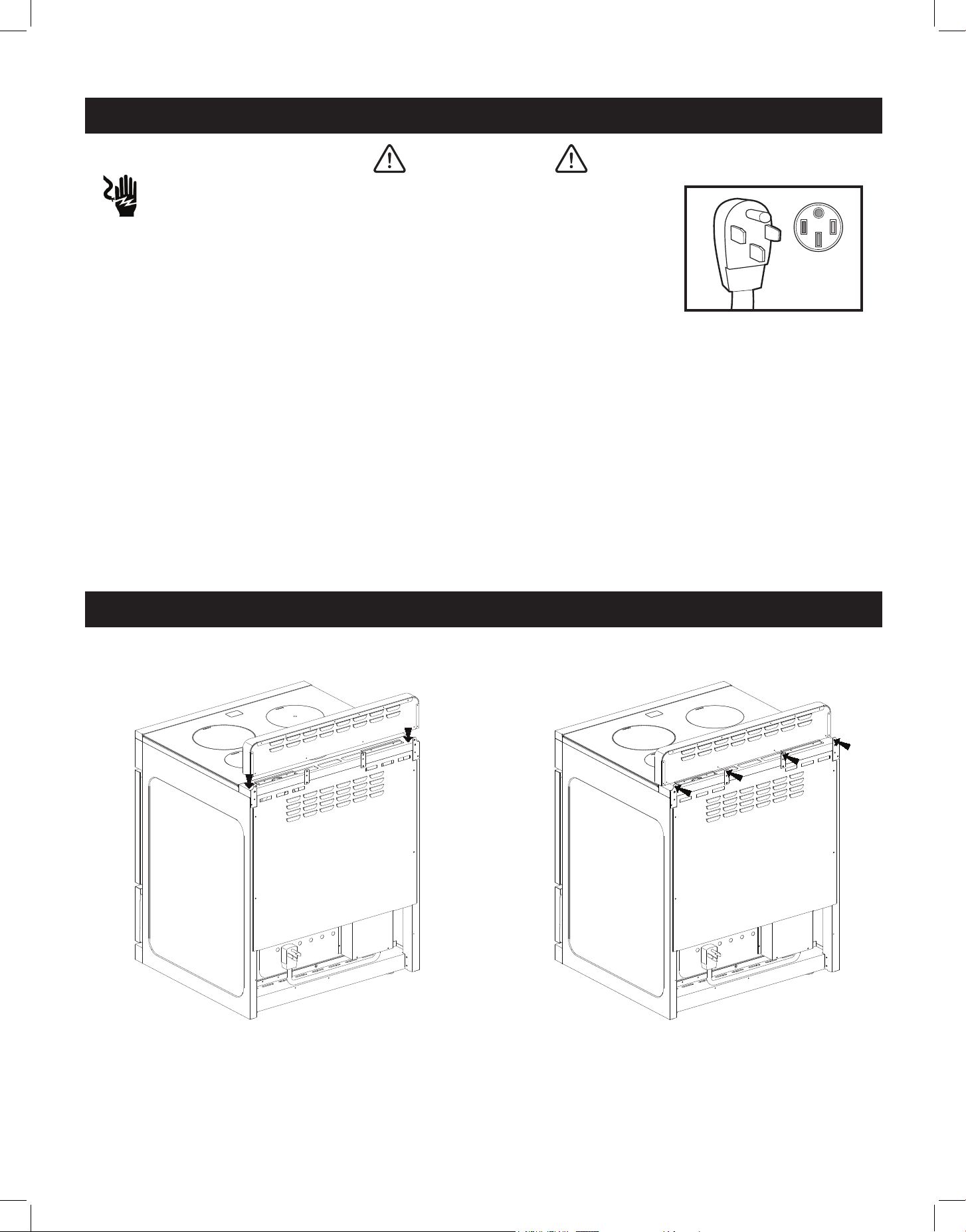
ELECTRICAL SHOCK HAZARD
• Plug into a grounded 4-prong outlet.
Ensure proper ground exists before using the range.
• Do not remove ground prong.
• Do not use an adapter or extension cord.
FAILURE TO FOLLOW THESE INSTRUCTIONS CAN RESULT IN DEATH, FIRE,
OR ELECTRICAL SHOCK.
FOR PERSONAL SAFETY, THIS APPLIANCE MUST BE PROPERLY GROUNDED.
This appliance is equipped with a four-prong grounding plug for your protection against
shock hazard and should be plugged directly into a properly grounded socket. Do not cut or
remove the grounding prong from the plug.
Do not under any circumstances cut or remove the green color (ground) prong from the
power plug. Electrical installation should comply with national and local codes.
It is recommended that a separate circuit, serving only your appliance be provided. Use
receptacles that cannot be turned o by a switch or pull chain.
GROUNDING INSTRUCTIONS
WARNING
HOW TO INSTALL THE BACKSPLASH
1. Align the backsplash to the rear part of
the cooktop as shown in the diagram.
STEP 1 STEP 2
2. Secure the backsplash to the cooktop
from the back using the 4 Phillips
head screws provided as shown in the
diagram.
12
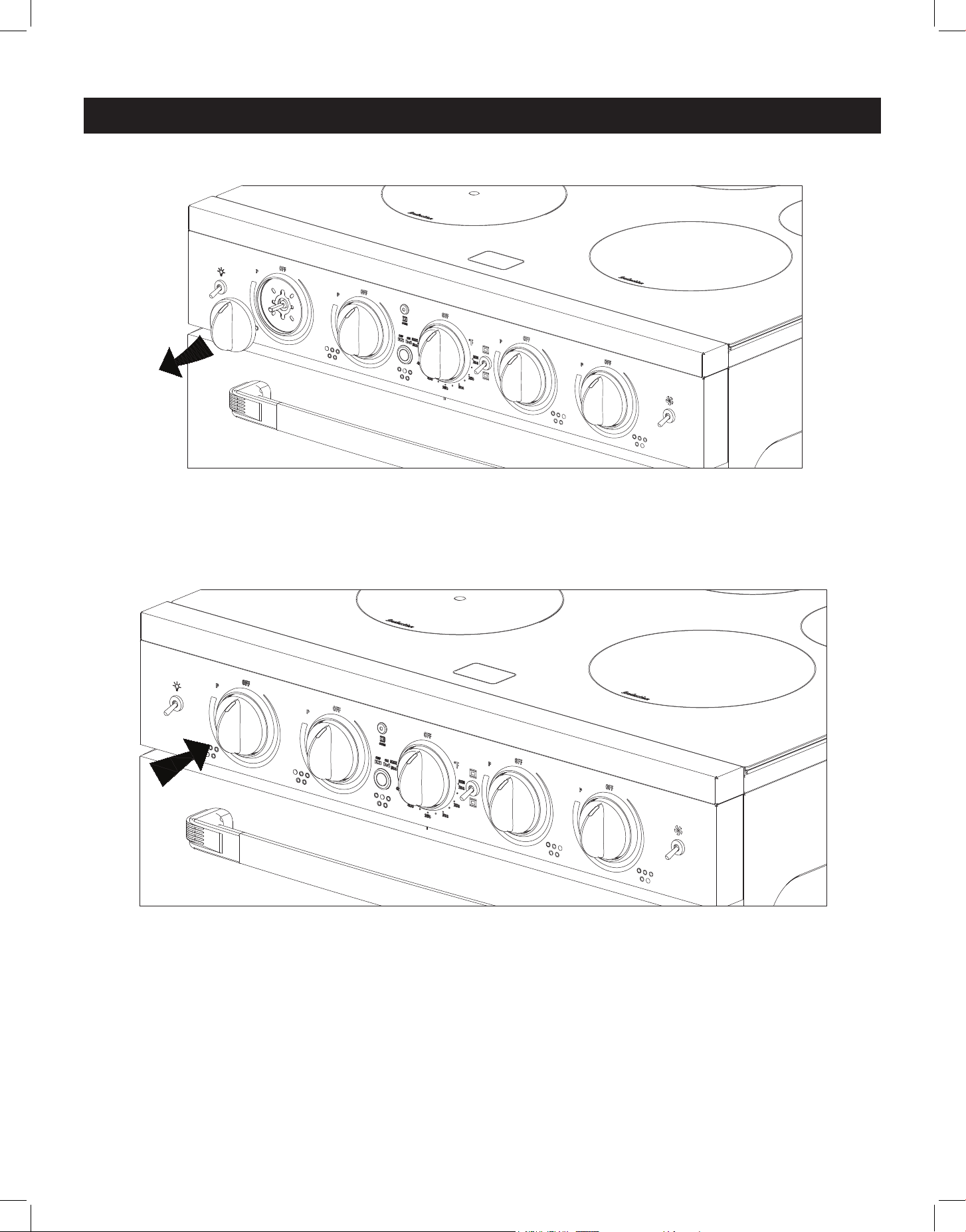
HOW TO INSTALL CONTROL KNOBS
1. To replace knobs, pull existing knob straight out and o stem.
2. Position new knob on the stem with the indicator mark pointing upwards to OFF, and
slowly push it into place.
STEP 1
STEP 2
13
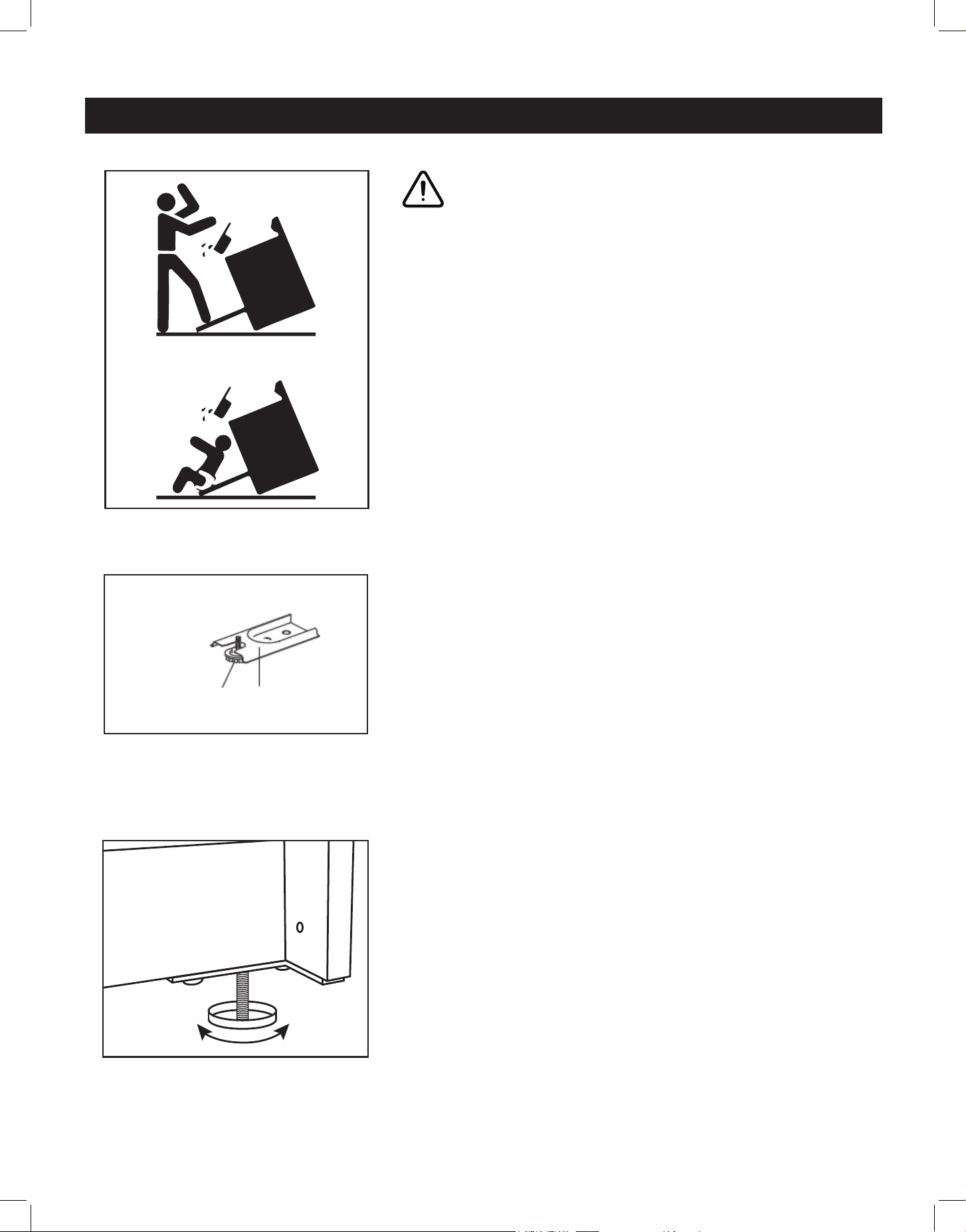
LEVELLING A FREE-STANDING RANGE
All free-standing ranges must be level to obtain proper
cooking results. The leveling legs should be screwed
into the corner brackets. Place pan or measuring cup
partially filled with water vor a level on the oven rack.
Adjust the leveling legs by hand until the range is level.
The top of the side panels should be level with the
counter top.
MAKING SURE THE ANTI-TIP BRACKET IS INSTALLED
• Slide the range forward
• Look for the anti-tip bracket securely attached to floor
• Slide range back so that the rear range foot is under
the anti-tip bracket.
• NOTE: Refer to page 14 for clearances required for
installing the anti-tip brackets.
• NOTE: Refer to page 16 for how to connect the range
to the anti-tip brackets.
x2
Range Foot Anti-tip Bracket
ANTI-TIP BRACKET INSTALLATION
WARNING
A child or adult can tip the range and be seriously
injured or killed. Install the anti-tip device to the
structure and/or the range. Verify the anti-tip device
has been properly installed and engaged. If the range
is moved, be sure to re-engage the range to the anti-tip
device.
Do not operate the range without the anti-tip device
in place and engaged. See installation instructions for
details. Failure to do so can result in serious burns and/
or death to children or adults.
14
IMPORTANT: Save these instructions for electrical inspector's use.
To eliminate the risk of burns or re by reaching over heated surface units, cabinet storage
space located above the surface units should be avoided. If cabinet storage is to be
provided the risk can be reduced by installing a range hood that projects horizontally a
minimum of 5 inches beyond the bottom of the cabinets.
IN THE EVENT OVERHEAD CABINETS ARE INSTALLED, THE MAXIMUM DEPTH OF
CABINETS INSTALLED ABOVE COOKING TOPS SHOULD BE 13”.
All units must be installed in accordance to minimum rear and side wall clearance and
clearances extended vertically above cooking top which are stated on the serial plate located
at the back of the range.
ANY OPENINGS IN THE WALL BEHIND THE UNIT AND IN THE FLOOR UNDER THE UNIT
MUST BE SEALED.
Note: Due to potential hazards it is recommended that storage cabinets NOT be installed
above the cooking surface.
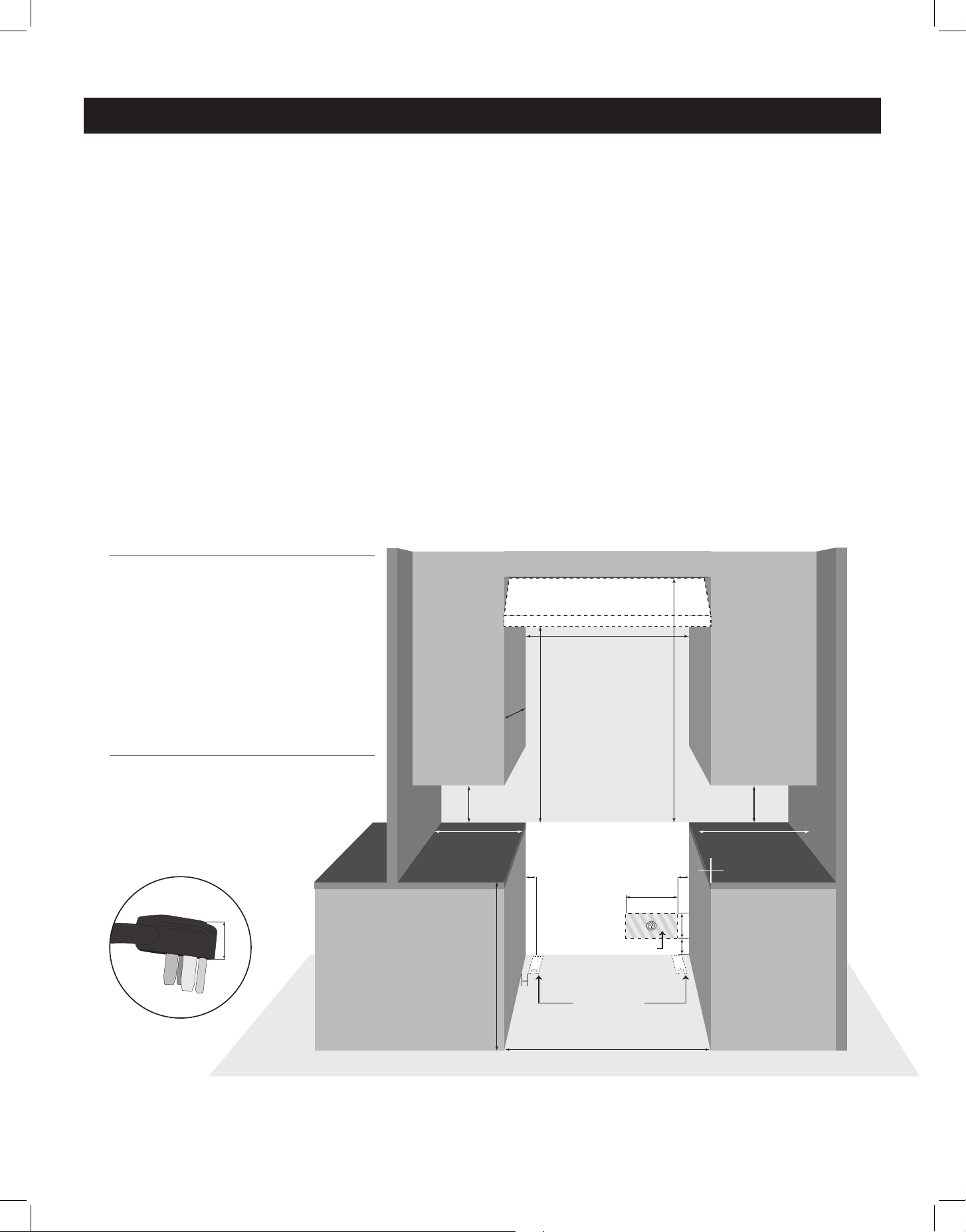
WALL CLEARANCES & ANTI-TIP LOCATION
30” (76.2 cm) or 36” (91.4 cm)
min 8”
(20.3 cm)
min. 8”
(20.3 cm)
min. 18”
(45.7 cm)
min. 30”
(76.2 cm)
to bottom of
ventilation hood
36”
(91.4 cm)
min. 48”
(122 cm)
minimum
to ceiling
min. 18”
(45.7 cm)
max. 13”
(33 cm)
B B
3.5” (8.9 cm)
D
E
opening for range plug
anti-tip brackets
30” (76.2 cm) or 36” (91.4 cm)
*ILLUSTRATION NOT TO SCALE
C
1.25”
(3.2 cm)
A
ELECTRIC RANGE - REQUIRED CLEARANCES
If range outlet is situated within the “opening for range plug”
(as shown), the plug will fit within this opening and the range
will sit flush against the wall.
If the outlet is situated elsewhere, the range will require an
allowance of at least 1.25” (3.2 cm) between the wall and
the back of the range to accomodate the plug.
A - From side of counter to side of range: 0”/0 cm
B - From side of counter to edge of opening for range plug: 2”/5 cm
C - From side of counter to outer edge of anti-tip bracket: 1.5”/3.8 cm
D - Width of opening for range plug: 15.7”/39.8 cm
E - Height of opening for range plug: 7”/17.8 cm
ELECTRICAL CONNECTION CLEARANCES
15
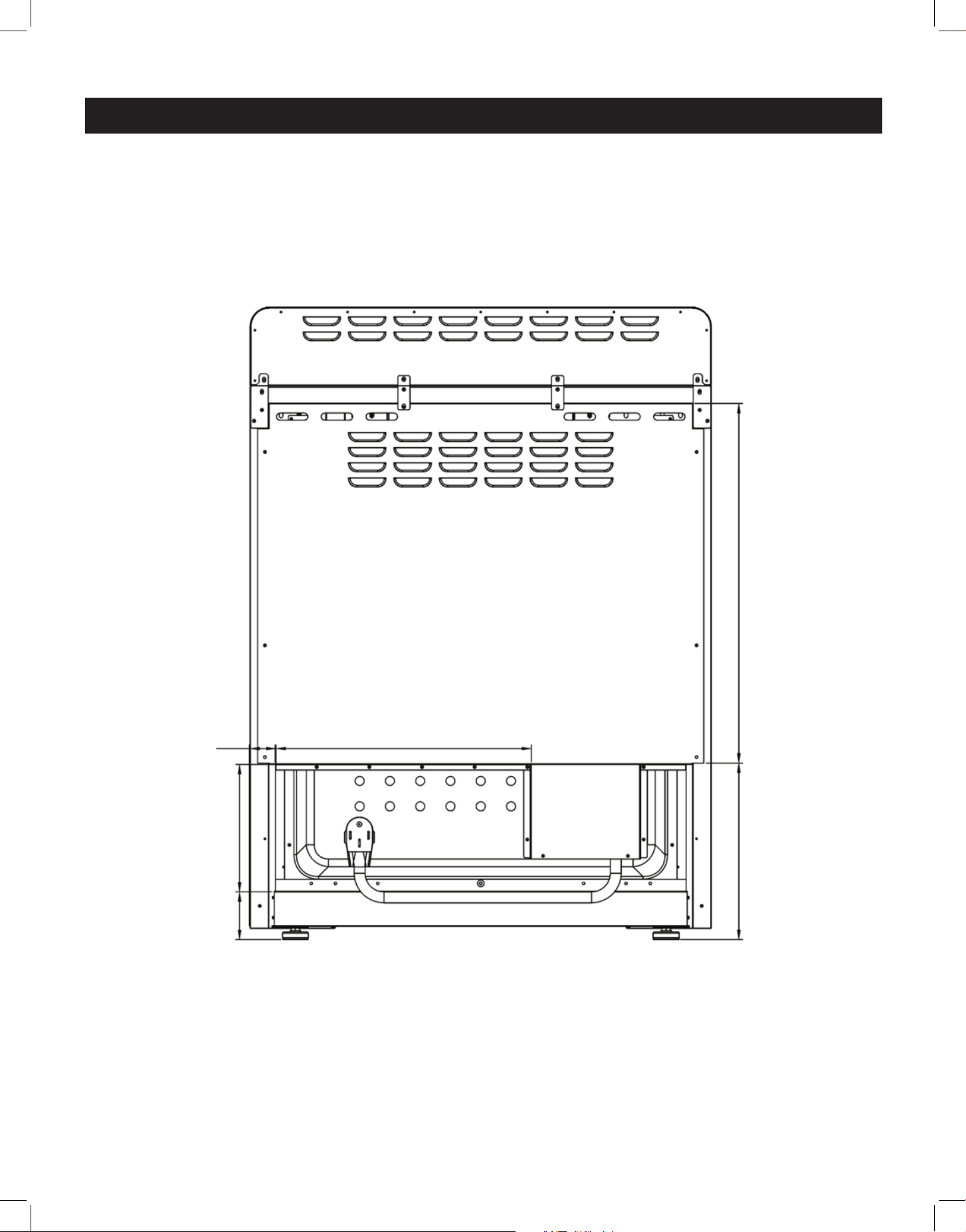
WALL CLEARANCES & ANTI-TIP LOCATION (continued)
BACK OF THE APPLIANCE FOR PLUG PLACEMENT
15.7" (39.8 cm)2" (5 cm)
7" (17.8 cm)
10.5" (26.6 cm) 25.5" (64.7 cm)
3.5"
(8.9 cm)
16
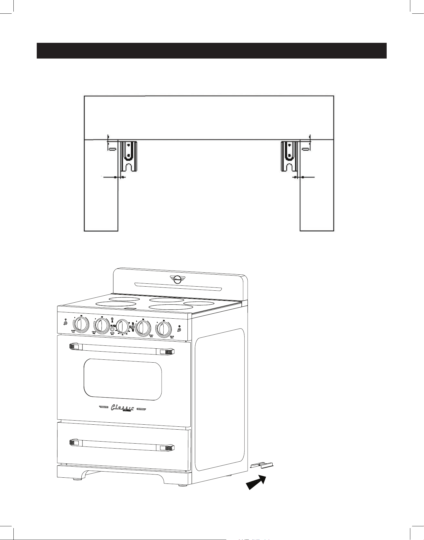
ANTI-TIP BRACKET LOCATION
WALL CLEARANCES & ANTI-TIP LOCATION (continued)
1.5" (3.8 cm) 1.5" (3.8 cm)
CONNECTING THE RANGE TO
THE ANTI-TIP BRACKET
• With the range slid forward
(away from the wall), look for
the anti-tip brackets securely
attached to floor on either side
of the range.
• Slide range back into its
installed position so that the
rear range feet slide under the
anti-tip brackets.
17
Ø160
1200W(P 1800W)
Ø180
100W
Ø160
1200W(P 1800W)
Ø230
2300W(P 3700W)
Ø210
2300W(P 2600W)
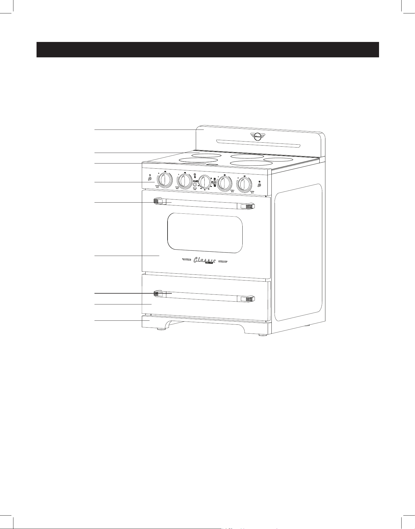
1. Backsplash with integrated oven vents
2. Cooktop
3. Display panel
4. Control panel
5. Oven handle
6. Oven door
7. Storage drawer handle
8. Storage drawer
9. Kick plate
10. Leveling legs (4)
PARTS & FEATURES
1
2
3
4
5
6
7
8
9
18
GETTING TO KNOW YOUR INDUCTION RANGE
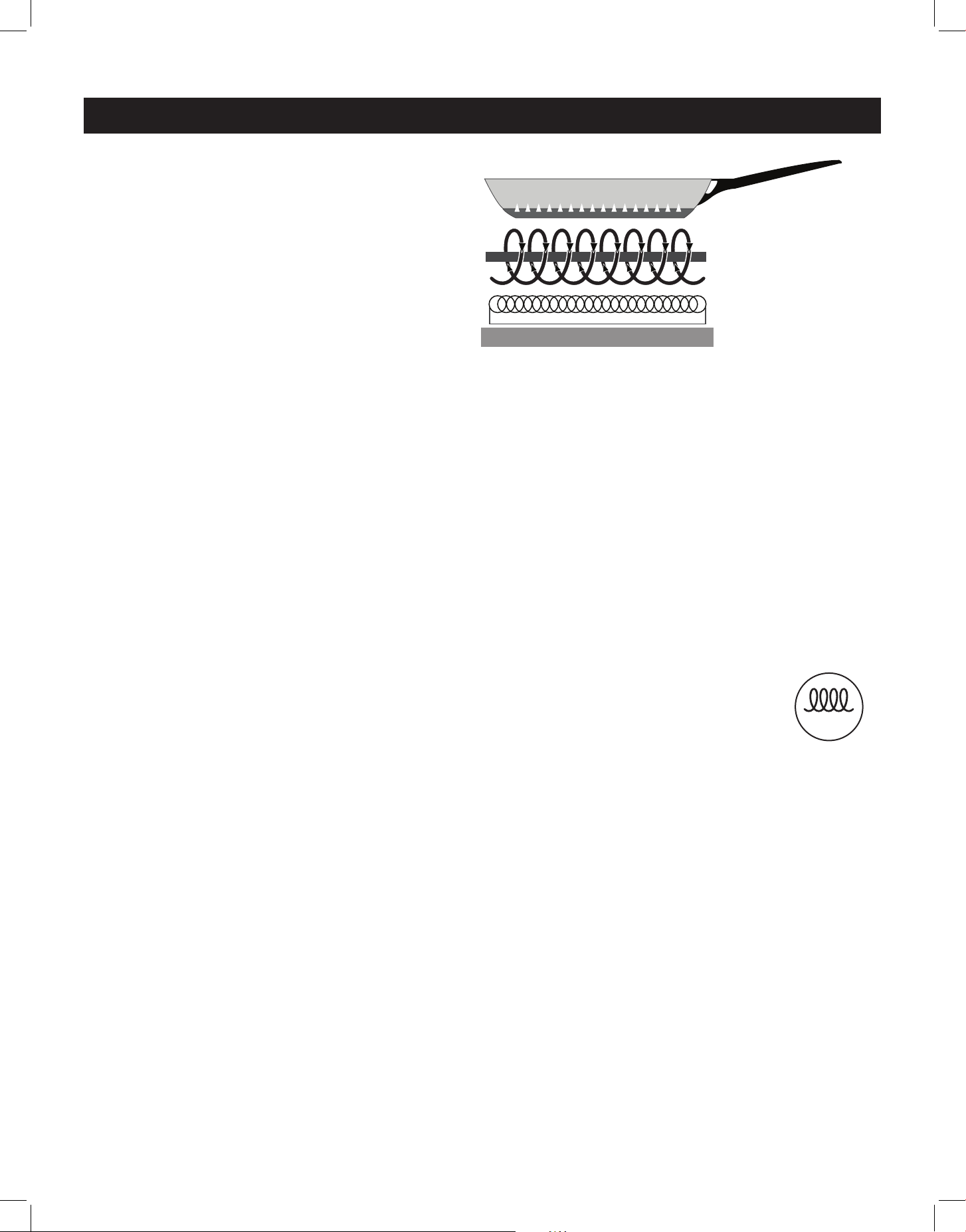
HOW YOUR INDUCTION RANGE WORKS
Induction ranges create an electromagnetic
current that oscillates between copper coils
within the cooktop surface and the cookware
itself, creating the heat that cooks your food.
Because this reaction occurs between the
connection of cookware and cooktop, there
is no physical heat created on the cooktop.
INDUCTION COOKING IS:
Faster – Induction cooktops heat up quickly, and allow for immediate and precise adjustments
to cooking temperature – no waiting for burners to heat up or cool down to achieve the ideal
cooking temperature.
Efcient – Induction cooktops use much less energy than traditional electric or gas cooktops,
cook food more quickly, and don't create residual heat, resulting in a cooler kitchen.
Safe – Since the induction cooktop only heats the cookware, the cooktop remains cool to the
touch, significantly reducing the risk of kitchen fires and/or accidents.
Easy to clean – With no heat generated on the surface of the induction cooktop, spills or
messes don’t burn or cook on to the surface, making them easy to wipe up.
INDUCTION COOKWARE: WHAT WORKS, AND WHAT DOESN’T
Because induction cooking uses an electromagnetic current to create heat,
induction cookware needs to be magnetic. Non-ferrous cookware such as aluminum,
copper and do not work with induction cooktops; instead, choose cast iron,
porcelain-enamelled cast iron, stainless steel or induction-ready cookware (identified
by this logo.)
How to test cookware for induction range compatibility:
• hold a magnet close to the bottom of the pot
• if the magnet pulls itself to the pot quickly and holds rm, this pot is induction-ready
• if the magnet’s draw is weak or non-existent, this pot isn’t suitable for induction cooking
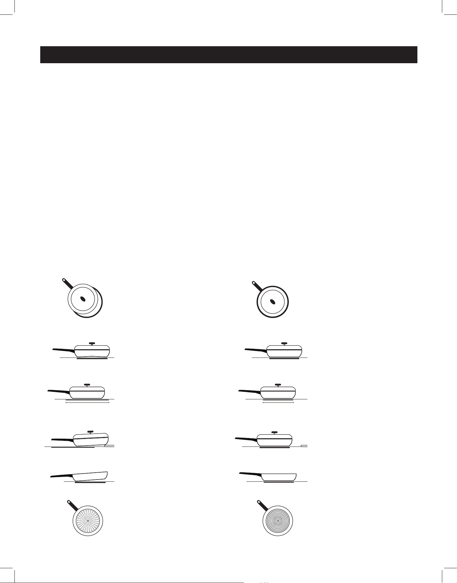
In order to maximize the contact between the cookware and the element, choose pots/pans
that have flat bottoms. Cookware the makes full contact with the element will produce the
best results; pots/pans with curved or warped bottoms will not heat evenly. Round cookware
that fits within the element ring is your best choice; cookware larger than the element ring can
be used, but heating will occur only above the element (within the ring's diameter.)
For wok cooking, only use a flat-bottomed wok. Do not use a wok with a support ring as the
wok will not contact the element.
NOTE: The warming zone is NOT an induction element, therefore it will work with flat-
bottomed pots/pans that are not specified for induction cooking.
magnetic field
cooktop surface
power coil
magnetic source (induction)
power supply
INDUCTION
19
PREPARING YOUR INDUCTION COOKTOP
Before using your induction cooktop for the first time, wipe the cooktop surface down with
a ceramic cooktop cleanser (like Weiman Cooktop Cleaner) and remove any residue with a
clean paper towel or soft cloth. This will leave a protective finish on the cooktop that helps to
protect against marks and scratches, and makes any cooking residue easier to clean up.
A NOTE ABOUT INDUCTION NOISE
Because induction heating is a magnetic function, some light vibration can occur with some
kinds of cookware, particularly those pots and pans that aren't perfectly flat on the bottom, or
that have loose handles or lids. Using heavier weight, high quality cookware (such as cast iron,
or enamelled cast iron) can help to eliminate vibrational noise.
When using more than one element, magnetic fields from adjacent elements may interact,
producing a low humming or whining noise. This noise can be reduced by raising or lowering
the power level settings of one or all of the elements. This humming noise is most noticeable
when the elements are set to high levels. Pans that completely contact and cover the element
rings will produce less noise.
Dierent cookware materials can product dierent, normal sounds. A low buzz may be heard
on element start-up if a pan's contents are cold, and will decrease as the pan heats up. You
can adjust/reduce the sound of this buzz simply by adjusting the heat setting higher or lower.
GETTING TO KNOW YOUR INDUCTION RANGE (continued)
INCORRECT CORRECT
Cookware is not
centred within the
heating element ring.
Cookware has a warped
bottom that isn't fully
contacting the element
Cookware does not
match the size of the
heating element
Cookware rests on the
cooktop trim/edge or
does not contact fully
with the element
Heavy handle causes
the pan to tilt
Cookware is not fully
magnetic/induction
compatible
Cookware is fully
magnetic/induction
compatible
Balanced cookware
ensures full contact
with element
Cookware makes
complete contact with
the element
Cookware matches or is
larger than the size of
the heating element
Cookware has a flat
bottom that fully
contacts the element
Cookware is centred
within the heating
element ring.
20
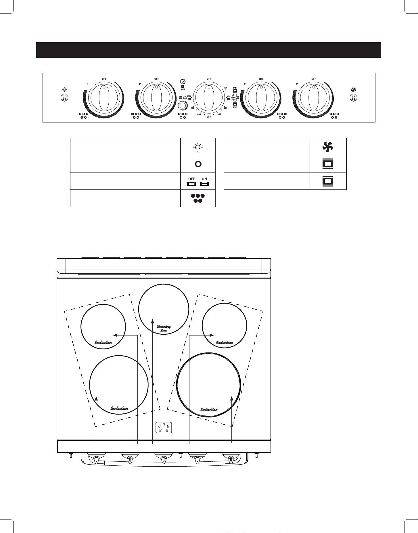
Convection fan switch
Broiler
Oven
RANGE CONTROLS
Ø160
1200W(P 1800W)
Ø180
100W
Ø160
1200W(P 1800W)
Ø230
2300W(P 3700W)
Ø210
2300W(P 2600W)
A B C D E
F
A Front left induction
element knob
B Back left induction
element knob
C Warming zone switch
D Back right induction
element knob
E Front right induction
element knob
F Display control panel
Oven light switch
Oven on/o indicator light
Warming zone on/o switch
Cooktop on/o indicator light
INDUCTION ELEMENT PLACEMENT
21
RANGE CONTROLS (continued)
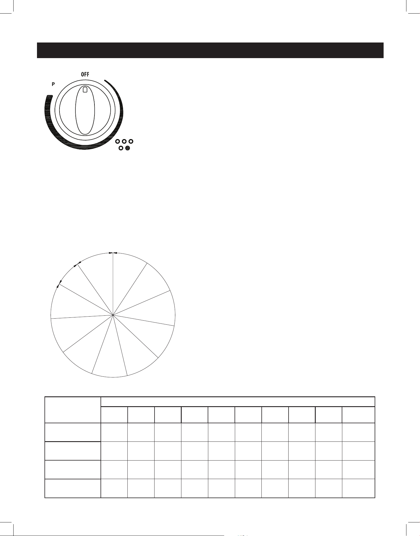
SETTING AND ADJUSTING THE ELEMENTS
• Select the desired element setting by pushing the
knob in and turning it to the right (clockwise.)
• Turn the knob to "MIN/1" for the lowest tempera-
ture, to "MAX/9" high temperature, or to P for
"Power Boost". You can adjust your element tem-
perature between the MIN/1 and MAX/9 settings
during the cooking process.
• To turn the element o, turn the knob to the left
(counter-clockwise) to 0 (OFF).
If the temperature in the element area is higher
than 60˚C, the setting/residual heat LED will dis-
play H on the control display panel.
• Left Front and Left Rear group: output power
limit of 3500W
• Right Front and Right Rear group: output power
limit of 3700W
1
0˚
2
3
4
5
6
7
8
9
300˚
MAX
MIN
OFF
P
25˚
knob will
not rotate
past this
area
ELEMENT CONTROL
The range comes with 4 elements and a central warming zone.
Each burner is designed with 9 heat settings and a Power Boost
setting (P).
This induction range also has a "warming zone" to keep hot,
cooked foods at serving temperature. To activate the warming
zone, press the "warming zone" button in. Press again to turn the
warming zone o.
NOTE: The warming zone should not be used to heat cold food.
POWER CONTROL
If an element is set to high for an extended period of time, or if additional elements are in
use on the cooktop, there might be a slight reduction in the power of the element set to
high. Ensure that any spills are wiped up promptly, as moisture under a pan may also cause a
reduction of heating power.
NOTE: When the front right element is set to Power Boost (P), the rear right element sets
to OFF. The rear right element can be used when the front right element is set to any level
between MIN/1 and MAX/9.
ELEMENT
LOCATION
POWER SETTINGS (watts)
1 2 3 4 5 6 7 8 9
POWER
BOOST
LEFT FRONT
100 150 200 250 350 600 1000 1500 2300 2600
LEFT REAR
100 150 200 250 300 350 600 1000 1200 1800
RIGHT FRONT
100 150 200 250 350 600 1000 1500 2300 3700
RIGHT REAR
100 150 200 250 300 350 600 1000 1200 1800
22
OPERATION OF RANGE
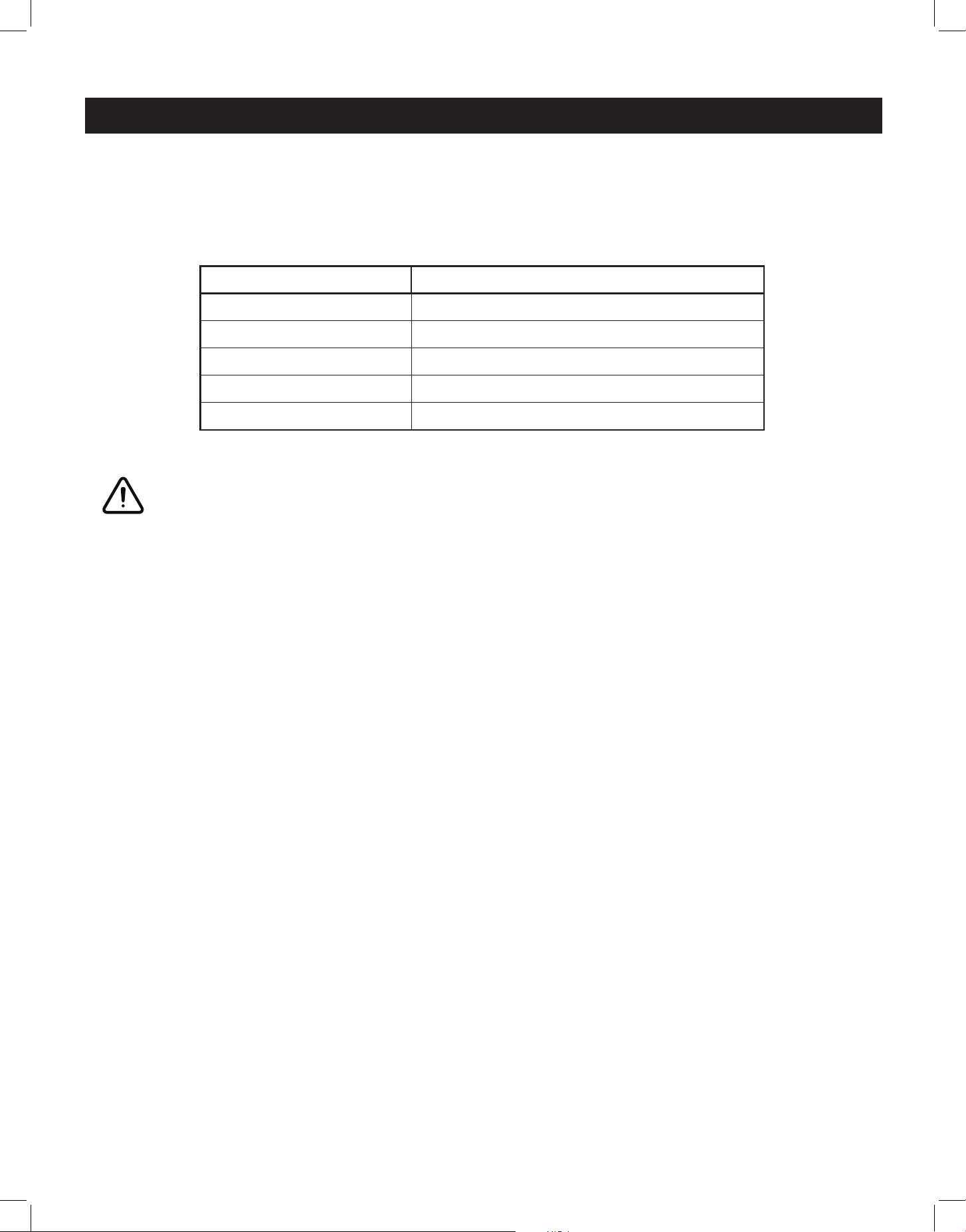
SYMBOL FUNCTION DESCRIPTION
Pan Detection
If a cooking area is turned on with no pot/pan placed
on it, or if the pot/pan is too small, the cooking area will
not heat up. After 10 seconds, the Pan Detection symbol
will display. This symbol will disappear and the element
will start to heat when an appropriately sized pot/pan is
placed on the cooking area.
If no appropriate, flat-bottomed pot/pan is detected
after 1 minute, the control panel will display 0.
Residual Heat
After an element has been turned o, the setting/
residual heat LED will display H on the corresponding
area of the control display panel if the temperature
in the cooking area is higher than 60˚C. Once this
temperature drops below 60˚C, the symbol will turn o.
Power Boost
function
The Power Boost function is a high-speed heating
function available on all cooking areas. To activate
Power Boost, turn the knob to P. The Power Boost
function will automatically downshift to MAX/9 after 5
minutes.
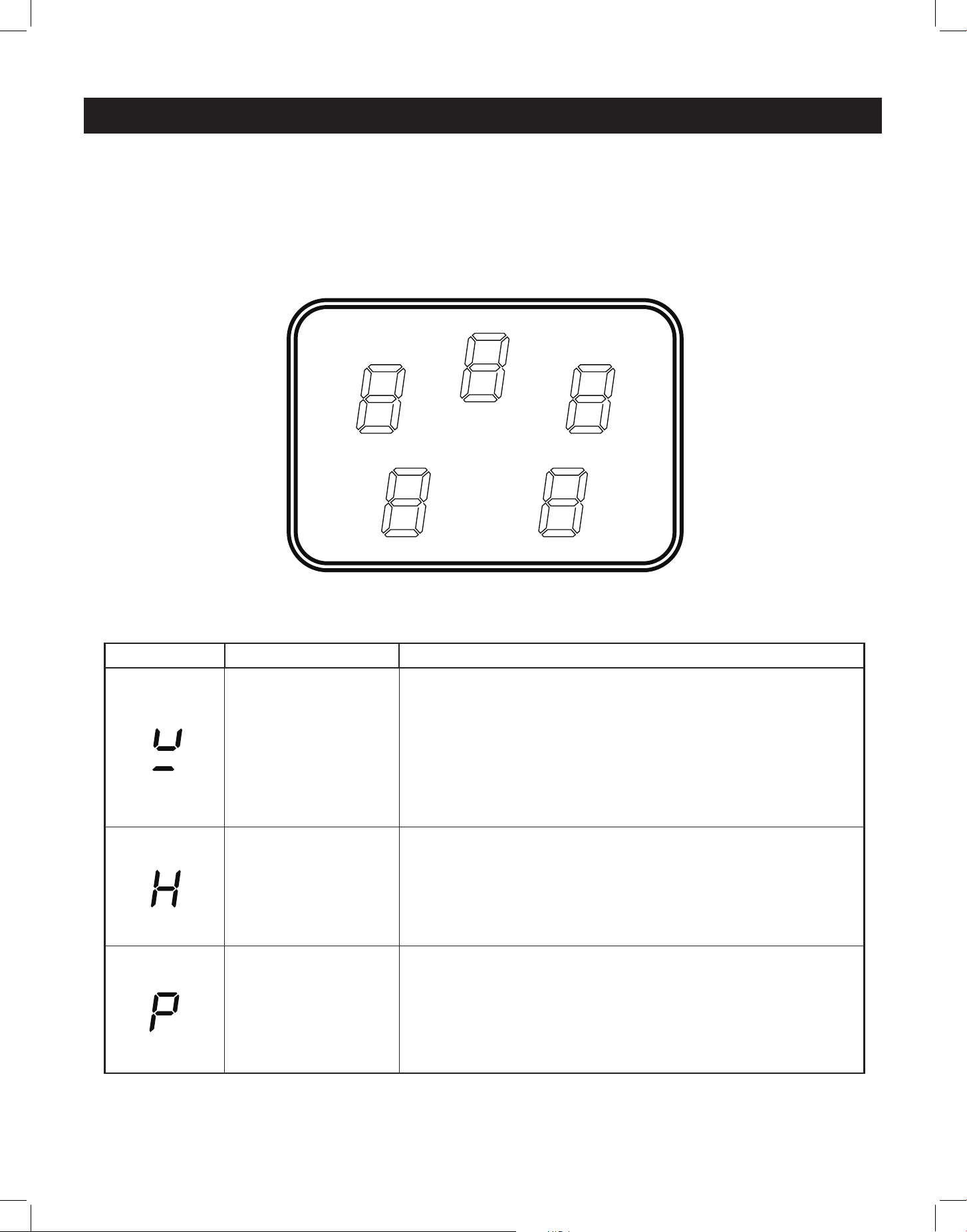
RANGETOP CONTROL DISPLAY
LEFT REAR
BURNER
Cook settings: 0 - 9
Power Boost: P
Residual heat: H
RIGHT REAR
BURNER
Cook settings: 0 - 9
Power Boost: P
Residual heat: H
WARMING ZONE
Warm settings: 0 - 1
(0 = o)
Residual heat: H
LEFT FRONT
BURNER
Cook settings: 0 - 9
Power Boost: P
Residual heat: H
RIGHT FRONT
BURNER
Cook settings: 0 - 9
Power Boost: P
Residual heat: H
23
OPERATION OF RANGE (continued)
ELEMENT SETTING SAFETY SHUTDOWN AFTER:
1-2
6 hours
3-4
5 hours
5
4 hours
6-9
1.5 hours
Power Boost
5 minutes
SAFETY SHUTDOWN FUNCTION
The induction range has a safety shuto feature to prevent the cooking areas from staying
active for a long time, which can waste energy.
COOKWARE TIPS
You must use compatible cookware with your induction range - only cast iron, porcelain-
enamelled cast iron, some stainless steel and induction-ready cookware can be used with
an induction range. Check the manufacturer’s recommendations for rangetop use, and
consult page 17 for more information.
• Pots with flat bottoms maximize the contact made with the magnetic field, making cooking
more ecient, while using tight-fitting lids help conserve energy and shorten cooking times.
• Pot size should match the element size. A slightly larger pan covers the entire element for
better eciency. Pots that are too small for the cooking area may trigger the Pan Detection
function.
• Pots should be centred on cooking zones. Uncentered pots may lead to uneven cooking.
WARNING
Make sure that the handles of cookware do not stick out over the edge of the range, to avoid
them being knocked over by accident. This also makes it more dicult for children to reach
the cooking pots/pans.
• To avoid damage to the cooktop, move pots and pans gently.
• Do not use the cooktop if the glass is cracked or broken. Using the cooktop can present a
risk of electric shock. Contact a qualified technician immediately.
• Avoid scratching the glass. The cooktop can be easily scratched by using items similar to
knives, sharp objects/edges, and jewelry.
• Avoid storing items that can melt or possibly catch fire on the glass cooktop, even if not in
use. Heat from the oven vent may cause items to melt or ignite.
24
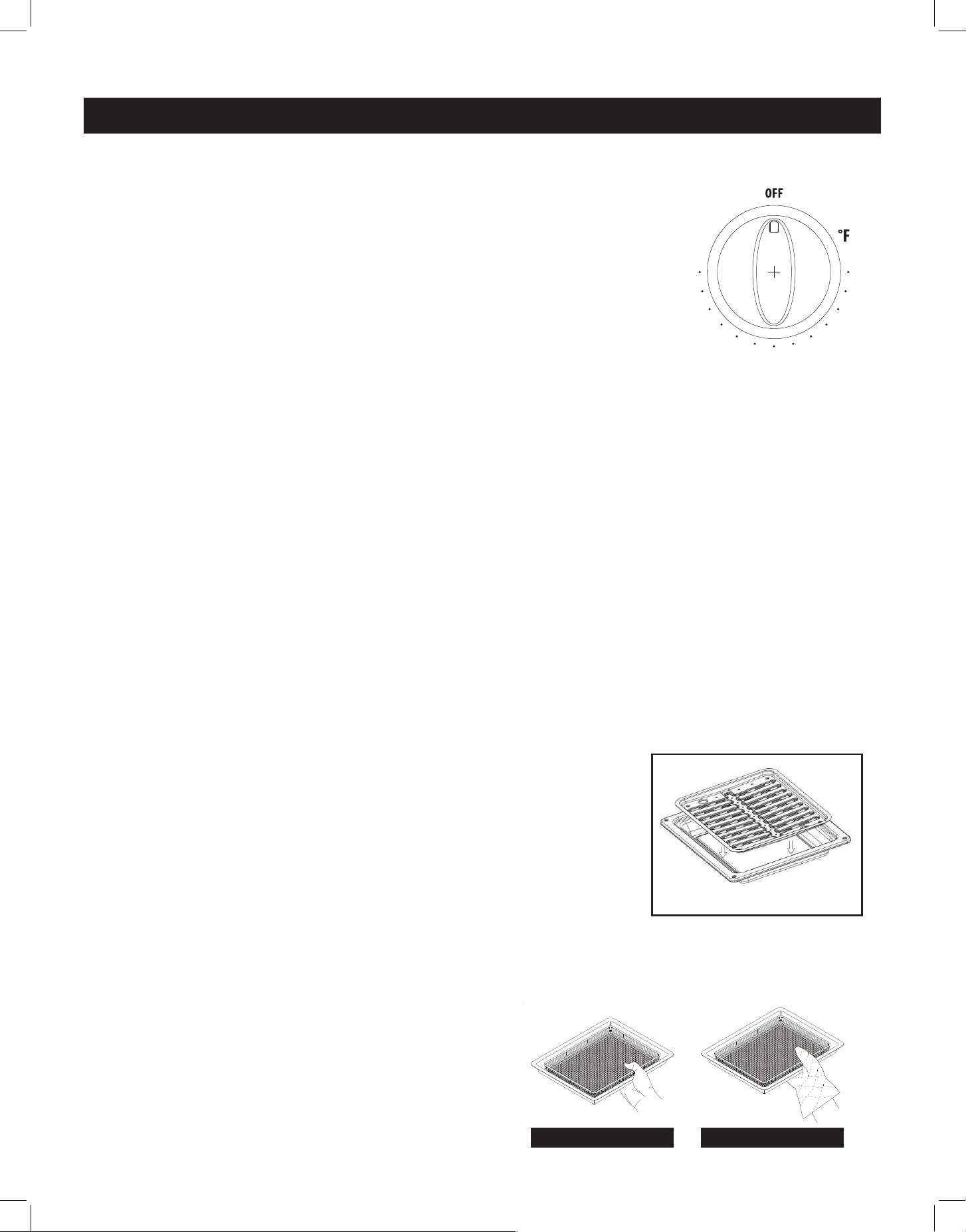
HOW TO USE THE OVEN
The oven is controlled by two separate switches: the Broil/Oven
switch is used to select the cooking mode, and the oven temperature
knob which is used to select the desired oven temperature. You must
first select the appropriate cooking mode (broil or oven/bake) and
then select the desired temperature.
The oven has three dierent heating modes:
Broil – 3400W (upper heating element)
Oven – 3400W (lower heating element)
Oven + Fan - 4638W (lower+ back heating element)
USING THE OVEN
• Switch the broil/oven rocker switch to “oven” mode
• Press the oven temperature knob in and turn it clockwise to select the desired temperature,
up to 500˚F max
• To switch the oven o, turn the oven temperature knob to the “O” position
NOTE: When the oven element is on, the indicator light will be lit regardless of the setting.
ATTENTION: The oven door becomes very hot during operation, be sure to use the handle to
open/close. Keep children away from the stove/oven when it is in use.
USING THE BROILER
• Switch the broil/oven rocker switch to “broil” mode
• Turn the oven temperature knob clockwise to the desired temperature on Broil
• To switch the broiler o turn the oven temperature knob too the “O” position
To use the broiler:
• Turn the Broil/Oven control knob to Broil, and turn the Oven
Temperature control knob clockwise to select the desired
temperature up to 500° F. Let the broiler preheat for about 5
minutes with the door closed.
• Place food in a broiler pan with a fitted grill. Always use the grill
so that the fat drips into the broiler pan, otherwise the juices may
spatter or catch fire. Do not broil without using a broiler pan.
• Position the broiler pan on the second level from the top, centered under the broil element.
• To switch o the oven, turn the thermostat control and function control knobs to the “O”
position.
IMPORTANT:
Always use suitable protective gloves when
inserting/removing broiler or air fryer crisper pan,
shelves, trays and other cooking utensils from the
oven.
The broiler function must always be used with
the oven door closed.
OPERATION OF OVEN
(Broiler Pan not Included)
500
450
400
350
300
250
200
MAX
MIN
OFF
ON
OVEN
OVEN
BROIL
Unique Appliances
30” Classic Induction
Control Panel
12 December 2023
Rev 1
Scale 1:1 Ink Color: Black ink on White and Pastels paint
Ink Color: Warm Gray 1C on Black paint
Screen: Use fine mesh only
500 Font: Myriad Pro Bold - 13.5pt
INCORRECT CORRECT
25
VERY IMPORTANT:
• The oven/broil should only be used with the door closed.
• Never obstruct the oven vent slots on the backsplash.
• Do not broil without using the broiling pan.
• Do not leave food under the broiler unattended.
• The cooktop surface may become hot when using the oven and/or broiler.
OVEN INDICATOR LIGHT
The oven indicator light will remain on until the oven knob is turned to the o position or the
desired temperature is reached in the oven.
OVEN THERMOSTAT
- The numbers printed on the control panel indicate the increasing oven temperature valve (˚F)
- To regulate the temperature, set the chosen number onto the control knob indicator.
COOKING IN FAHRENHEIT/CELCIUS
The oven temperatures are listed in degrees Fahrenheit
on the knob (˚F) - use the chart at right to determine the
equivalent temperature in degrees Celcius (˚C).
OPERATION OF OVEN (continued)
Knob setting
(temperature
in ˚F)
Corresponding
temperature
in ˚C
200 93
250 121
300 149
350 177
400 204
450 232
500 260
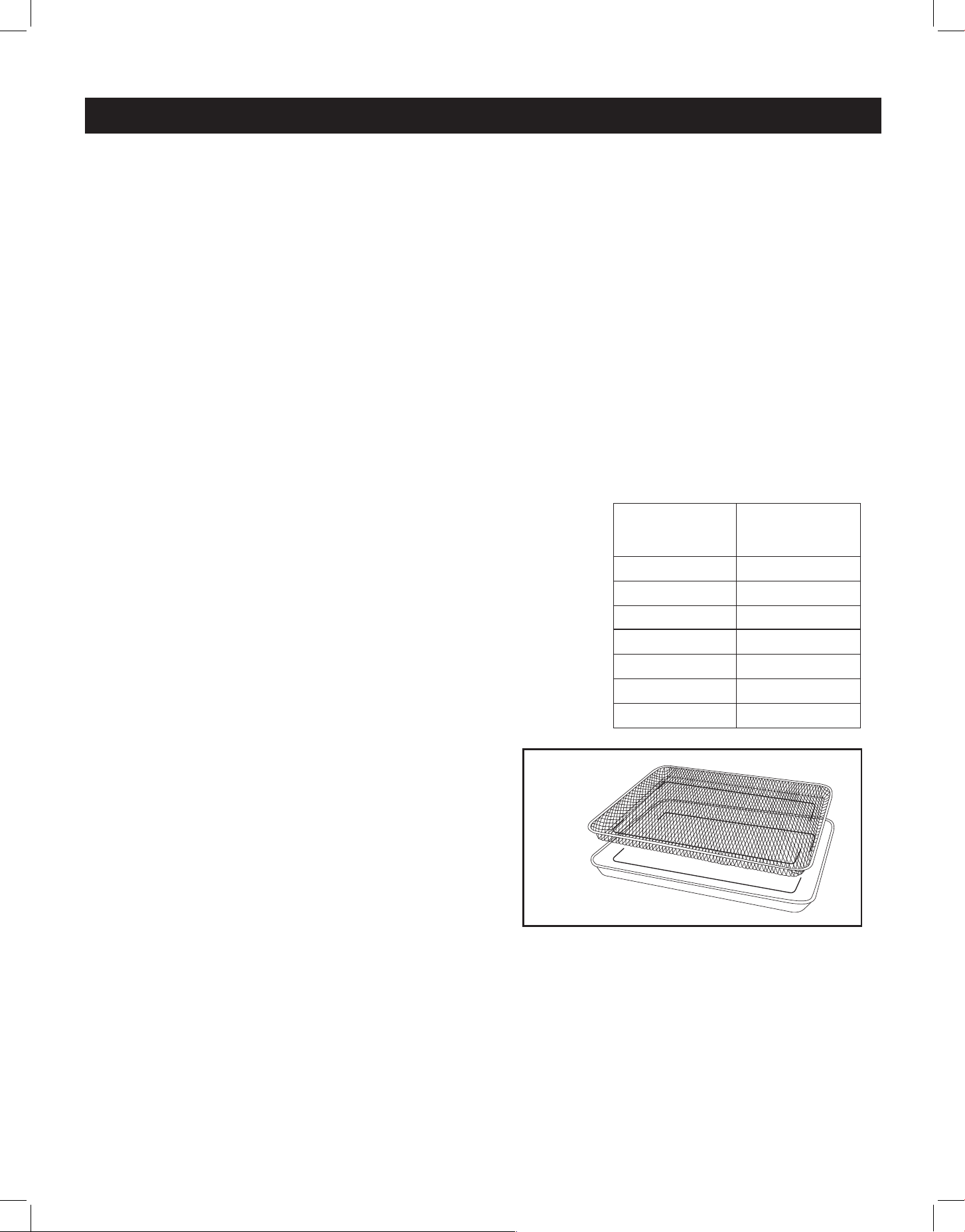
USING THE AIR FRYER CRISPER TRAY AND PAN
• Position the oven racks to the middle of the oven.
• Set the broil/oven rocker switch to OVEN and
switch the convection fan to ON
• Turn the oven temperature knob clockwise to the
desired temperature (up to 500˚F) and let the
oven preheat for about 5 minutes with the door
closed.
• Place food in a single layer in the mesh air fryer
crisper tray with its fitted pan beneath.
To promote even cooking and browning, do not over-crowd food in the crisper tray.
• Baste or mist food lightly with oil to help ensure a crispy exterior and moist interior.
• Cook food according to package/recipe directions. Food should be shaken/stirred once or
twice during the cooking process to ensure even cooking and a crispy exterior.
For example: French fries cook to perfection in about 18 minutes at 400˚F, shaking/stirring
them halfway through the cooking time.
• When finished cooking, remove the air fryer crisper tray from the oven, turn the convection fan
to OFF, and turn the oven temperature knob to the “OFF” position
Air Fryer Crisper Tray and Pan

26
CARE & MAINTENANCE
Important: Before performing any cleaning and/or maintenance, disconnect the appliance
from the electrical supply.
• It is best to clean both the range surfaces and the enameled surfaces when they are cold.
• Avoid leaving alkaline or acidic substances (lemon juice, vinegar, etc.) on surfaces.
• For best results, use cleansers specially made for cleaning induction cooktops. Avoid using
cleaning products with a chlorine or acidic base.
• The oven should be cleaned after every use, using suitable products. Heating the oven to
its hightest temperature for 30 minutes will reduce most grime and debris to ash, making
clean-up easier.
CLEANERS AND CLEANING MATERIALS
Do not use harsh cleaners or degreasers on or around functional parts (valves, controls, etc., or
aluminum tubing). This will damage or drastically reduce the life of the part.
Use only a mild solution of soap and water on back guards, aluminum control panels and
painted surfaces. Never use harsh abrasives or cleaning powders that may scratch or mar the
surface. Make sure the cleaners and cleaning materials are suitable for use on the area to be
cleaned. Always keep cleaning materials in a safe place. Never use a sharp metal scraper to
clean glass, porcelain, or painted surfaces.
COOKTOP
Use a sponge and a commercial cooktop cleaner (like Weiman Cooktop Cleaner) for best results.
To remove heavier grease and stubborn residue, a plastic scraper can be used to help loosen
residue: follow the cleaner's application instructions.
KNOBS
Pull forward on the knobs to remove them (you can slide dental floss behind the knob and use it
to pull the knob forward if needed.) Wash knobs with water mixed with a mild detergent. To avoid
scratches, do not use an abrasive cleaner or any abrasive action. Dry the knobs with a soft cloth
and reinstall.
AIR FRYER CRISPER TRAY AND PAN
Using a soft, damp cloth, wipe away any crumbs or baked-on food residue. Place the air fryer
crisper tray and pan in the dishwasher for easy clean-up, or soak both in a solution of hot water
and dish detergent for 10 minutes and gently scrub any residue o with a scrub brush or sponge.
Once clean, thoroughly dry both the crisper tray and pan before storing.
USING COMMERCIAL OVEN CLEANERS
Commercial oven cleaners may be used on porcelain-lined ovens; however, many cleaners are
very strong, and it’s important to follow instructions carefully. Ensure adequate ventilation, and be
sure to wear rubber gloves to protect your hands.
After using such cleaners, thoroughly rinse the oven with a solution of 1 tablespoon vinegar to 1
cup of water. Oven cleaners can coat or damage the thermostat sensing device (the long tube in
the oven) so that it will not respond to temperature accurately. If you use an oven cleaner, do not
let it contact the sensing bulb, or any chrome, aluminum, or plastic part of the range.
Do not apply or allow the cleaner to come in contact with any parts or surfaces other than
the oven interior.
27
REPLACING THE OVEN LIGHT
• Let the oven cavity and broil element cool down.
• Switch o the electric supply.
• Remove the protective cover.
• Unscrew light bulb counter clockwise.
• Replace the bulb with an E14 120V 25W 300°C bulb.
• Reassemble the protective cover.
NOTE: Oven bulb replacement is not covered by your warranty.
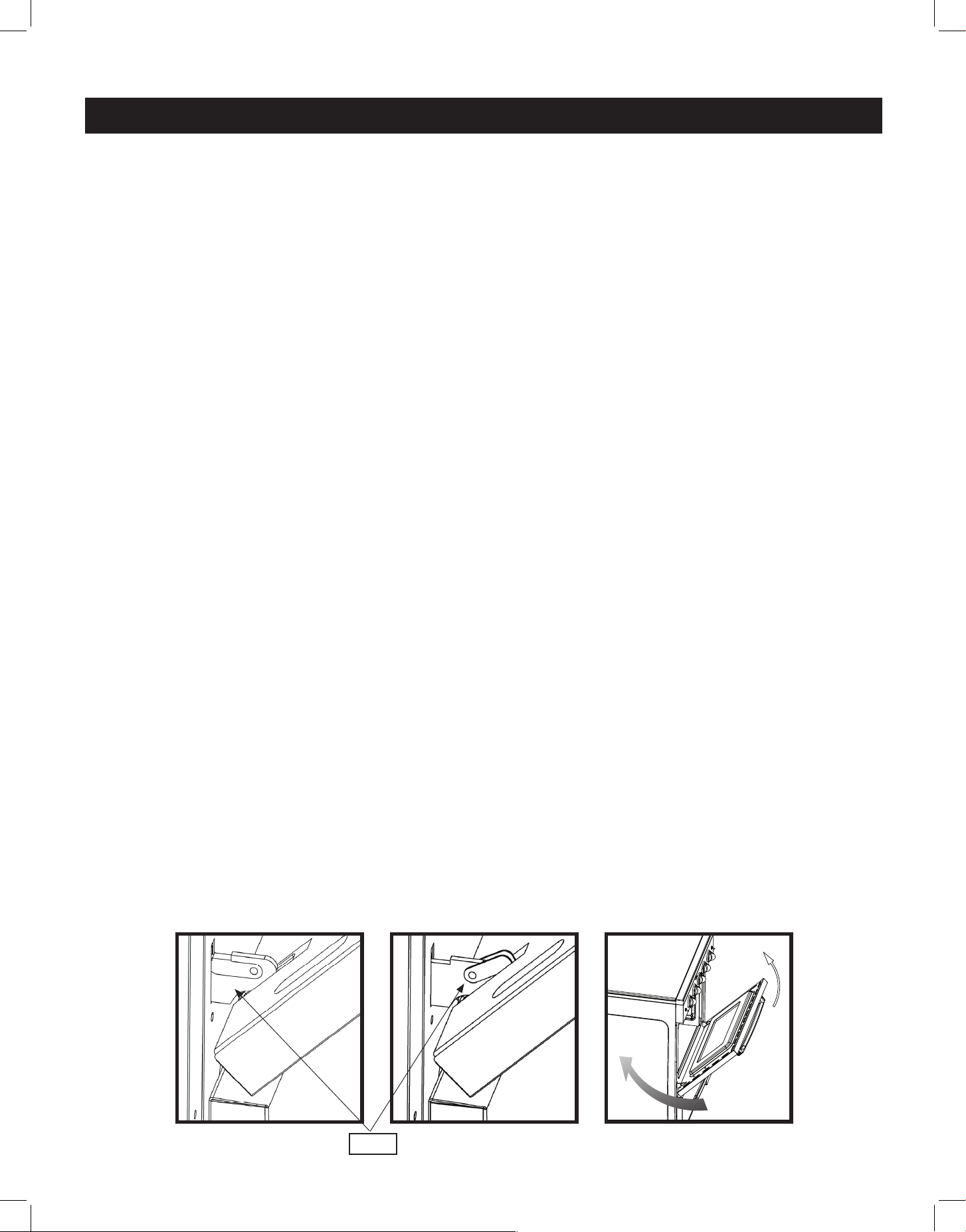
REMOVING THE OVEN DOOR FOR CLEANING
To facilitate oven cleaning, it is possible to remove the door for better access. Please
follow the instructions carefully:
The oven door can easily be removed as follows:
• Open the door to fully.
• Lift the left and right hooks on the hinge figure (A,B).
• Hold the door as shown in figure (C) on a 45 degree angle.
• Gently close the door until the hooks touch the door, then lift at a 45 degree angle
• Set the door on a soft flat surface.
• To replace the door, repeat the above steps in reverse order.
CARE & MAINTENANCE (continued)
(C)(B)(A)
HOOK
USING ALUMINUM FOIL IN OVEN
WARNING: Do not cover any slots, holes or passages in the oven bottom, or cover an entire
rack with materials such as aluminum foil. Doing so blocks air ow through the oven and may
trap heat, causing a re hazard.
Aluminium foil, when improperly used, can be a cause of range fires. Make certain that vents or
air openings aren’t covered by the foil. If the vents located along the sides of the oven bottom
are blocked, poor cooking will result.
Never cover a rack completely. A piece of foil slightly larger than the cookware can be placed
on the rack beneath the cookware.
Remove and discard aluminum foil after each use. This will help prevent grease and spilled food
from accumulating and becoming a fire hazard.
28
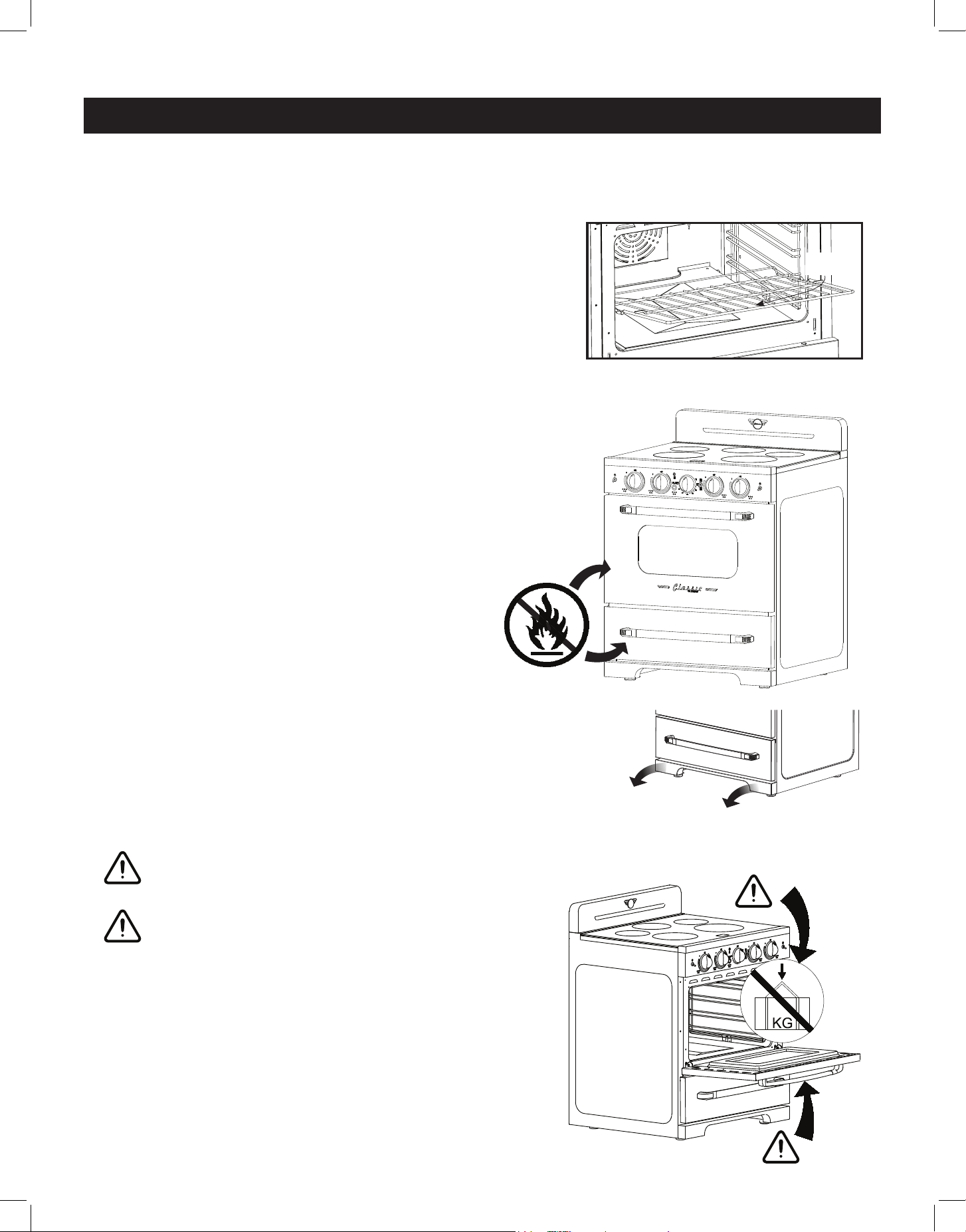
OVEN RACK INSTALLATION AND REMOVAL
• The oven racks are provided with a safety catch to prevent accidental removal
• They must be inserted as shown
• To remove, pull the rack towards you and tilt it
upwards to remove the safety catch from the side
support rails
• To replace the racks, slide the safety catch between the
side support rails with the rack tilted slightly upwards,
then slowly lower the rack down to level as you push
it all the way in
CARE & MAINTENANCE (continued)
SAFETY
CATCH
DO NOT STORE FLAMMABLE MATERIAL IN THE OVEN
OR IN THE BOTTOM DRAWER
Only store heat-resistant pots, pans and trays in the
drawer as it gets very hot when the oven is on.
NOTE: Do not store plastic items (or pots and pans
with plastic handles) in your drawer.
REMOVING THE KICKPLATE FOR CLEANING
For better access when cleaning underneath the range, remove
the magnetic kickplate at the bottom of the range by pulling it
forward.
CAUTION
Do not place heavy objects on the open oven door.
CAUTION
DO NOT PULL THE OVEN HANDLE TO THE LEFT OR
RIGHT WITH FORCE DURING INSTALLATION.
DO NOT USE THE OPEN OVEN DOOR TO MOVE OR
POSITION THE APPLIANCE.
Ø160
1200W(P 1800W)
Ø180
100W
Ø160
1200W(P 1800W)
Ø230
2300W(P 3700W)
Ø210
2300W(P 2600W)
DO NOT PLACE HEAVY OBJECTS ON
THE OVEN DOOR.
NE PLACEZ PAS D’OBJETS LOURDS
SUR LA PORTE DU FOUR.
DO NOT PULL THE OVEN HANDLE TO THE LEFT
OR RIGHT WITH FORCE DURING INSTALLATION.
NE TIREZ PAS LA POIGNÉE DU FOUR VERS LA
GAUCHE OU LA DROITE AVEC FORCE PENDANT
L'INSTALLATION.
29
CLEANING THE RANGE
REPAIR PARTS
When repair parts are needed, contact the dealer from whom the range was purchased. If your
range was purchased from a source other than an appliance dealer, contact the manufacturer at
the address shown in this manual.
MOISTURE
During the initial heat-up of your range, heat mixing with the cooler air in the oven cavity may
produce fogging of the door glass or a collection of water on the door. To prevent this, open the
oven door for the first few seconds of initial oven heat-up. This will allow the moist air within the
oven to escape, without the forming of visible moisture on the range. The amount of moisture
will depend upon the humidity of the air and water content of the food being cooked. Fogging
and/or dripping water can occur in geographic locations of high humidity.
PROBLEM
PROBLEM
POSSIBLE CAUSE/SOLUTIONS
POSSIBLE CAUSE/SOLUTIONS
The cooktop makes
faint clicking sounds
during operation
• This is a normal sound of the electronic switches that maintain
cooking temperature
The cooktop makes
a loud humming
noise
• Improper cookware can cause loud humming noises of up to 63 dB
• Ensure you are using induction compatible cookware
The cooktop makes
a low humming
noise when more
than 2 elements
are being used
simultanelously
• This is a normal noise due to interacting magnetic fields
This humming is most noticeable when the elements are set to high
• Raise or lower the power level settings of one or all of the elements
to reduce/eliminate noise
• Ensure that pots/pans make complete contact with surface and fully
cover the element ring
Surface units will not
maintain a rolling
boil or frying rate is
not fast enough
• Bottom of pan is not making adequate contact with cooktop
Use heavy-weight pans that have flat bottoms
• Use appropriate induction-ready cookware - the size of the pan
bottom should match the diameter of the surface unit selected
Foods cook slowly
or not at all
• Improper cookware being used - use induction compatible
cookware
Many common appliance problems can be solved by following the suggestions below.
TROUBLESHOOTING
30
TROUBLESHOOTING (continued)
PROBLEM
PROBLEM
POSSIBLE CAUSE/SOLUTIONS
POSSIBLE CAUSE/SOLUTIONS
Surface units do not
operate.
• You have blown a household fuse or tripped a circuit breaker
• The surface units are not plugged in correctly
• You have not set the element control correctly
Control knobs will
not turn
• For cooktop control knobs, be sure to push them in before turning
• For oven control knobs, be sure to turn the knob in the right
direction
Oven light does not
work
• Light bulb is loose or defective - check and replace if necessary
• The oven light switch is broken - contact Unique’s technical service
department for instructions
Oven does not work.
• Ensure that the rocker switch is set to OVEN
• You have blown a household fuse or tripped a circuit breaker
• You have not set the control knobs correctly
Broil does not work
• Ensure that the rocker switch is set to BROIL
• You have blown a household fuse or tripped a circuit breaker
Food does not broil
properly
• The oven control switch is not set to BROIL
• Improper rack position being used - check and reposition if needed
• Ensure that cookware is suitable for broiling
• Oven thermostat is defective - contact Unique’s technical service
department for instructions
Food does not bake
properly
• The oven control knob is not set properly
• Rack position is incorrect - check and reposition if needed
• Improper cookware is being used - replace if necessary
• Oven thermostat is defective - contact Unique’s technical service
department for instructions
31
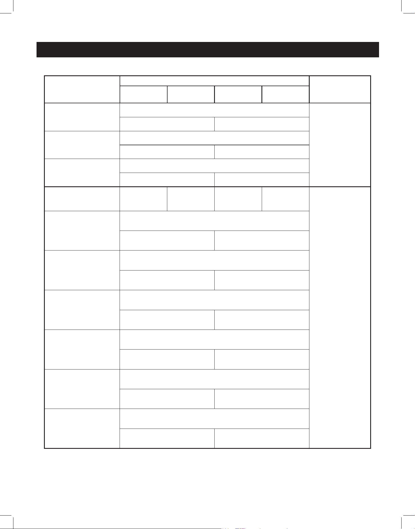
ERROR CODES
ERROR
CATEGORY
ERROR CODE DISPLAYED
REPAIR
STATUS
A digital
tube
B digital
tube
C digital
tube
D digital
tube
Power board failure
or communication
error
F1
NOT
RECOVERABLE
Left Module Right Module
Line coil NTC
failure
F3
Left Module Right Module
IGBT NTC failure
F4
Left Module Right Module
10s Press button
for more than 10
seconds
- - - -
RECOVERABLE
NTC overheating of
wire coil
E1
Left Module Right Module
IGBT overheating
E2
Left Module Right Module
High voltage
protection
E3
Left Module Right Module
Under voltage
protection
E4
Left Module Right Module
NTC line coil
NTC removal
protection
E5
Left Module Right Module
IGBT NTC removal
protection
E6
Left Module Right Module
32
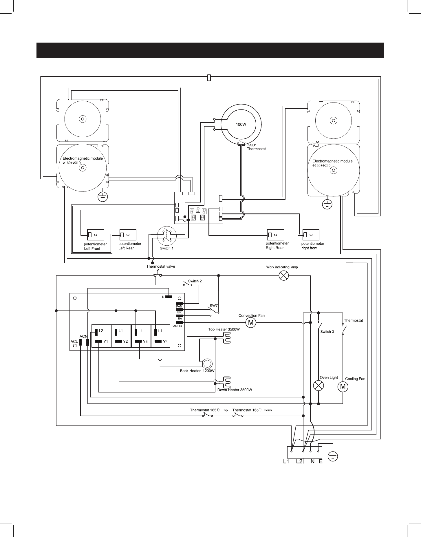
WIRING DIAGRAM
33
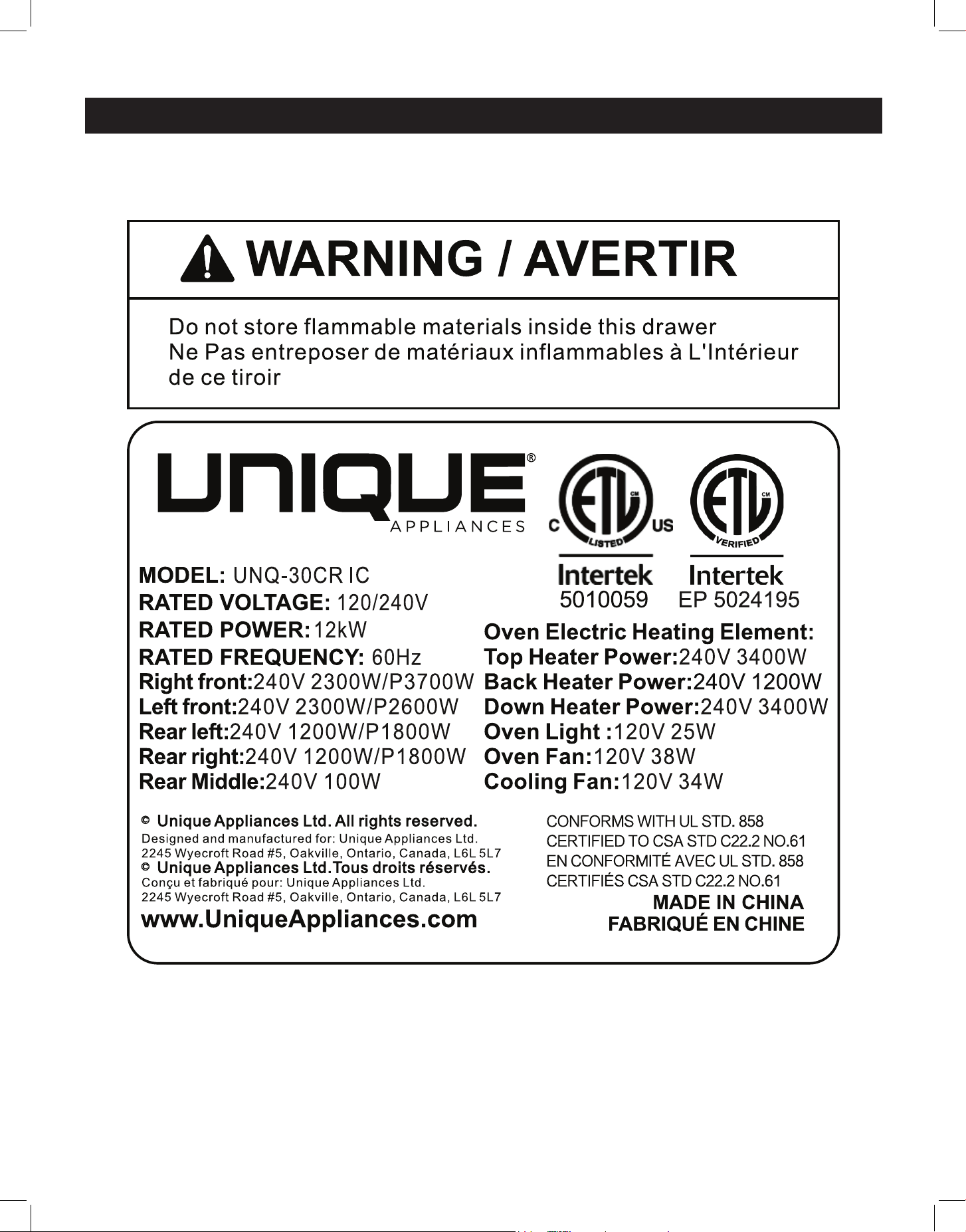
RATING LABEL

34
Unique Appliances Ltd. (hereafter “Unique”) warrants that this UNIQUE appliance is free from manufacturer’s
defects in material and workmanship under normal usage and service under the following terms.
Parts Warranty
This appliance has been designed for domestic household use. If properly installed, adjusted and operated under
normal conditions in accordance with printed instructions, it will satisfactorily perform the functions that are
generally expected of this type of appliance.
If the appliance fails to do so because of a defect in material or workmanship within one year from the original date of purchase:
Unique will at our option, repair, exchange, or correct by other means Unique consider appropriate, any part(s) Unique finds to
be defective except for the surface finish.
Ownership
This Warranty is made only to the first purchaser (”original purchaser”) who acquires this appliance for his/her own use and will
be honored by Unique Appliances and by the Seller. Purchaser must retain their receipt as proof of purchase date.
Warranty Conditions
This warranty does not apply to any appliance that has been subjected to alterations, misuse, abuse (including damage by
foreign agents or chemicals), accident, improper installation or service, delivery damage, or other than normal household use
and service. This UNIQUE appliance must be serviced regularly as outlined in the Owner’s Manual. In case of damage, the owner
must provide proof of purchase, Model, and Serial Number to the selling dealer or Unique Appliances. This warranty is LIMITED
STRICTLY to the terms indicated herein, and no other expressed warranties or remedies thereunder shall be binding on Unique.
Purchaser’s Responsibilities
The purchaser will be responsible for the costs of any service calls requested to demonstrate or confirm the proper operation
of the appliance, the installation, or to correct malfunctions in the appearance created by the operation of the appliance in a
manner not prescribed by or cautioned against in the use and care instructions.
Model and Serial Number
The appliance model number and serial number can be found on a rating plate on the range. The purchaser should always refer
to the model and serial number when talking to or contacting the dealer from whom the appliance was purchased.
EXCLUSIONS
Save as herein provided, by Unique, there are no other warranties, conditions, representations or guarantees, express or implied,
made or intended by Unique or its authorized distributors and all other warranties, conditions, representations or guarantees,
including any warranties, conditions, representations or guarantees under any Sale of Goods Act or like legislation or statute is
hereby expressly excluded. Save as herein provided, Unique shall not be responsible for any damages to persons or property,
including the unit itself, howsoever caused or any consequential damages arising from the malfunction of the unit and by the
purchase of the unit, the purchaser does hereby agree to indemnify and hold harmless Unique from any claim for damages to
persons or property caused by the unit
Removal or disfigurement of the rating plate will void the warranty. The purchaser will be responsible for any expenses
involved in making the range readily accessible for servicing. The purchaser will be responsible for any extra charges where the
installation is in a remote location such as un-assumed roads, islands, areas known as cottage country, more than 75 km outside a
metropolitan area, or where a technician is not available. Freight damage is not covered by this warranty.
GENERAL PROVISIONS
No warranty or insurance herein contained or set out shall apply when damage or repair is caused by any of the following:
1) Power failure.
2) Damage in transit or when moving the appliance.
3) Improper power supply such as low voltage, defective house wiring or inadequate fuses.
4) Accident, alteration, abuse or misuse of the appliance such as inadequate air circulation in the room or abnormal operating
conditions (ie. extremely high or low room temperature).
5) Use for commercial or industrial purposes (ie. If the appliance is not installed in a domestic residence).
6) Fire, water damage, theft, war, riot, hostility, acts of God such as hurricanes, floods etc.
7) Service calls resulting in customer education.
8) Improper Installation (ie. building-in of a free standing appliance or using an appliance outdoors that is not approved for
outdoor application, including but not limited to: garages, patios, porches or anywhere that is not properly insulated or
climate controlled).
Proof of purchase date will be required for warranty claims; retain bills of sale. In the event that warranty service is required,
present the proof of purchase to our authorized service depot.
Nothing within this warranty shall imply that Unique will be responsible or liable for any direct or indirect loss of foods
caused by failure in operation.
Factory Assistance
If the purchaser is unable to locate an authorized dealer/service agent, or if the purchaser does not receive satisfaction from the
dealer, they may contact Unique Appliances Customer Service directly at Toll Free 1-877-427-2266 or 905-827-6154.
WARRANTY
35
For questions related to the operation, safety or the purchase of your appliances, please contact your
dealer for more information. For general information, contact our customer service department:
APPLIANCE INFORMATION
(manual copy - keep with your records)
To make care and servicing of your appliance easy and ecient, please record the following infor-
mation for future reference:
Model:
Serial Number:
Purchased From:
Date Purchased:
APPLIANCE INFORMATION
CONTACT US
Toll-free
1-877-427-2266 or 1-905-827-6154
(available during regular business
hours, 8:30 am to 4:30 pm, EST.
Website
www.uniqueappliances.com
Email
info@UniqueAppliances.com
Scan the QR Code
or
Visit our website at https://uniqueappliances.com/product-registration/ to
register your product.
PRODUCT REGISTRATION

36
©2024 Unique Appliances Ltd., 2245 Wyecroft Road #5,
Oakville, Ontario, Canada, L6L 5L7
www.UniqueAppliances.com