
© 20 GeoVision, Inc. All rights reserved.
Under the copyright laws, this manual may not be copied, in whole or in part,
without the written consent of GeoVision.
Every effort has been made to ensure that the information in this manual is
accurate. GeoVision, Inc. makes no expressed or implied warranty of any kind
and assumes no responsibility for errors or omissions. No liability is assumed
for incidental or consequential damages arising from the use of the information
or products contained herein. Features and specifications are subject to
change without notice.
GeoVision, Inc.
9F, No. 246, Sec. 1, Neihu Rd.,
Neihu District, Taipei, Taiwan
Tel: +886-2-8797-8377
Fax: +886-2-8797-8335
http://www.geovision.com.tw
Trademarks used in this manual: GeoVision,the GeoVision logo and GV
series products are trademarks of GeoVision, Inc. Windows is the registered
trademark of Microsoft Corporation.
December20
Scan the following QR codes for product warranty and technical support
policy:
[Warranty] [Technical Support Policy]

i
Notice
The features described in the manual vary among camera models and firmware
versions. Some features may not be available in your camera.
Safety Instruction
⚫ This product is intended to be supplied by a Listed Power Unit, marked with 'Limited
Power Source', 'LPS' on unit, output rated minimum 12V/2 A or POE 48V/ 350mA or
AC24V (depending on models), no more than 2000m altitude of operation and Tma=60
Deg.C.
⚫ As for the modes with PoE function, the function of the ITE being investigated to IEC
60950-1 standard is considered not likely to require connection to an Ethernet network
with outside plant routing, including campus environment and the ITE is to be connected
only to PoE networks without routing to the outside plant.
⚫ Do not attempt to disassemble the camera; in order to prevent electric shock, do not
remove screws or covers.
⚫ There are no user-serviceable parts inside. Please contact the nearest service center as
soon as possible if there is any failure.
⚫ Avoid aiming the camera directly towards extremely bright objects, such as, sun, as this
may damage the image sensor.
⚫ Please follow the instructions to install the camera. Do not reverse the camera, or the
reversing image will be received.
⚫ Do not operate it in case temperature, humidity and power supply are beyond the limited
stipulations.
⚫ Keep away from heat sources such as radiators, heat registers, stove, etc.
⚫ Do not expose the product to the direct airflow from an air conditioner.
⚫ This manual is for using and managing the product. We may reserve the rights of
amending the typographical errors, inconsistencies with the latest version, software
upgrades and product improvements, interpretation, and modification. These changes
will be published in the latest version without special notification.
⚫ All pictures, charts, images in this manual are only for description and explanation of our
products. The ownerships of trademarks, logos and other intellectual properties related to
Microsoft, Apple and Google belong to the above-mentioned companies.
⚫ This manual is suitable for face detection network cameras.
ii
Disclaimer
⚫ With regard to the product with internet access, the use of product shall be wholly at your
own risks. Our company shall be irresponsible for abnormal operation, privacy leakage or
other damages resulting from cyber attack, hacker attack, virus inspection, or other internet
security risks; however, Our company will provide timely technical support if necessary.
⚫ Surveillance laws vary from country to country. Check all laws in your local region before
using this product for surveillance purposes. We shall not take the responsibility for any
consequences resulting from illegal operations.
Cybersecurity Recommendations
⚫ Use a strong password. At least 8 characters or a combination of characters, numbers, and
upper and lower case letters should be used in your password.
⚫ Regularly change the passwords of your devices to ensure that only authorized users can
access the system (recommended time is 90 days).
⚫ It is recommended to change the service default ports (like HTTP-80, HTTPS-443, etc.) to
reduce the risk of outsiders being able to access.
⚫ It is recommended to set the firewall of your router. But note that some important ports
cannot be closed (like HTTP port, HTTPS port, Data Port).
⚫ It is not recommended to expose the device to the public network. When it is necessary to
be exposed to the public network, please set the external hardware firewall and the
corresponding firewall policy.
⚫ It is not recommended to use the v1 and v2 functions of SNMP.
⚫ In order to enhance the security of WEB client access, please create a TLS certificate to
enable HTTPS.
⚫ Use black and white list to filter the IP address. This will prevent everyone, except those
specified IP addresses from accessing the system.
⚫ If you add multiple users, please limit functions of guest accounts.
⚫ If you enable UPnP, it will automatically try to forward ports in your router or modem. It is
convenient for users, but this will increase the risk of data leakage when the system
automatically forwards ports. Disabling UPnP is recommended when the function is not
used in real applications.
⚫ Check the log. If you want to know whether your device has been accessed by
unauthorized users or not, you can check the log. The system log will show you which IP
addresses were used to log in your system and what was accessed.
iii
Regulatory Information
FCC Information
1. FCC compliance
The products have been tested and found in compliance with the council FCC rules and
regulations part 15 subpart B. These limits are designed to provide reasonable protection
against harmful interference. This equipment generates uses and can radiate radio frequency
energy and, if not installed and used in accordance with the instruction manual, may cause
harmful interference to radio communication. However, there is no guarantee that interference
will not occur in a particular installation. The user will be required to correct the interface at his
own expense in case the harmful interference occurs.
2. FCC conditions:
Operation of this product is subject the following two conditions: (1) this device may not cause
harmful interface, and (2) this device must accept any interference received, including
interference that may cause undesired operation.
CE Information
The products have been manufactured to comply with the following directives.
EMC Directive 2014/30/EU
RoHS
The products have been designed and manufactured in accordance with Directive EU RoHS
Directive 2011/65/EU and its amendment Directive EU 2015/863 on the restriction of the use
of certain hazardous substances in electrical and electronic equipment.
2012/19/EU (WEEE directive): The Directive on waste electrical and electronic
equipment (WEEE Directive). To improve the environmental management of WEEE,
the improvement of collection, treatment and recycling of electronics at the end of
their life is essential. Therefore, the product marked with this symbol must be
disposed of in a responsible manner.
Directive 94/62/EC: The Directive aims at the management of packaging and packaging
waste and environmental protection. The packaging and packaging waste of the product in
this manual refers to must be disposed of at designated collection points for proper recycling
and environmental protection.
REACH(EC1907/2006): REACH concerns the Registration, Evaluation, Authorization and
Restriction of Chemicals, which aims to ensure a high level of protection of human health and
the environment through better and earlier identification of the intrinsic properties of chemical
substances. The product in this manual refers to conforms to the rules and regulations of
REACH. For more information of REACH, please refer to DG GROWTH or ECHA websites.

iv
Table of Contents
Contents
Notice ........................................................................................................................................................................................ i
Safety Instruction ................................................................................................................................................................... i
Contents ................................................................................................................................................................................. iv
Chapter 1 Introduction ...................................................................................................................................................... 1
Chapter 2 Network Connection ....................................................................................................................................... 2
2.1 LAN .......................................................................................................................................................................... 3
2.1.1 Access Through IP-Tool ............................................................................................................................. 3
2.1.2 Directly Access Through IE Mode in Edge .............................................................................................. 5
2.2 WAN ......................................................................................................................................................................... 7
Chapter 3 Live View ........................................................................................................................................................... 9
Chapter 4 Network Camera Configuration ................................................................................................................. 17
4.1 System Configuration .......................................................................................................................................... 17
4.1.1 Basic Information ...................................................................................................................................... 17
4.1.2 Date and Time ........................................................................................................................................... 17
4.1.3 Local Config ............................................................................................................................................... 19
4.1.4 Storage ....................................................................................................................................................... 20
4.1.5 Configuring Fisheye Parameters ............................................................................................................ 23
4.2 Image Configuration............................................................................................................................................. 24
4.2.1 Display Configuration ............................................................................................................................... 24
4.2.2 Video / Audio Configuration ..................................................................................................................... 27
4.2.3 OSD Configuration .................................................................................................................................... 30
4.2.4 Video Mask ................................................................................................................................................ 32
4.2.5 ROI Configuration ..................................................................................................................................... 33
4.2.6 Lens Control............................................................................................................................................... 34
4.3 Alarm Configuration ............................................................................................................................................. 35
4.3.1 Motion Detection ....................................................................................................................................... 35
4.3.2 Exception Alarm ........................................................................................................................................ 38
4.3.3 Alarm In ...................................................................................................................................................... 40
4.3.4 Alarm Out ................................................................................................................................................... 41
4.3.5 Alarm Server .............................................................................................................................................. 42
4.3.6 Audio Alarm ................................................................................................................................................ 42
4.3.7 Light Alarm ................................................................................................................................................. 44
4.3.8 Video Exception ........................................................................................................................................ 44
4.3.9 Audio Exception ........................................................................................................................................ 45
4.4 Event Configuration ............................................................................................................................................. 47
4.4.1 Object Abandoned / Missing .................................................................................................................... 49
4.4.2 Video Exception ........................................................................................................................................ 52
4.4.3 Line Crossing ............................................................................................................................................. 55
4.4.4 Region Entrance ....................................................................................................................................... 61
4.4.5 Region Exiting ........................................................................................................................................... 64
4.4.6 Target Counting by Line ........................................................................................................................... 65
4.4.7 Target Counting by Area........................................................................................................................... 70
4.4.8 Region Intrusion ........................................................................................................................................ 73
4.4.9 Face Detection .......................................................................................................................................... 76
4.4.10 Crowd Density ......................................................................................................................................... 82
4.4.11 Heat Map .................................................................................................................................................. 84
4.4.12 Video Metadata ....................................................................................................................................... 87
4.4.13 Loitering Detection .................................................................................................................................. 90
4.4.14 Illegal Parking Detection ........................................................................................................................ 92
4.5 Service ................................................................................................................................................................... 94
4.5.1 GV-Cloud VMS .......................................................................................................................................... 94
4.5.2 GV-Center V2 ............................................................................................................................................ 95
4.6 Network Configuration ......................................................................................................................................... 96
4.6.1 TCP/IP ........................................................................................................................................................ 96
4.6.2 Port .............................................................................................................................................................. 97
4.6.3 DDNS .......................................................................................................................................................... 98

v
4.6.4 SNMP ......................................................................................................................................................... 99
4.6.5 802.1x ....................................................................................................................................................... 100
4.6.6 RTSP ........................................................................................................................................................ 101
4.6.7 RTMP ........................................................................................................................................................ 102
4.6.8 UPnP ......................................................................................................................................................... 103
4.6.9 Email ......................................................................................................................................................... 104
4.6.10 FTP ......................................................................................................................................................... 105
4.6.11 HTTP POST ........................................................................................................................................... 107
4.6.12 HTTPS .................................................................................................................................................... 108
4.6.13 QoS ......................................................................................................................................................... 109
4.6.14 TS Multicast ............................................................................................................................................110
4.7 Security Configuration ........................................................................................................................................ 111
4.7.1 User Configuration ................................................................................................................................... 111
4.7.2 Online User ...............................................................................................................................................113
4.7.3 Block and Allow Lists ...............................................................................................................................113
4.7.4 Security Management..............................................................................................................................114
4.8 Maintenance Configuration ................................................................................................................................115
4.8.1 Backup and Restore ................................................................................................................................115
4.8.2 Reboot .......................................................................................................................................................117
4.8.3 Upgrade .....................................................................................................................................................117
4.8.4 Operation Log ...........................................................................................................................................118
4.8.5 Advanced ..................................................................................................................................................118
4.8.6 Debug Mode .............................................................................................................................................118
Chapter 5 Search ............................................................................................................................................................. 119
5.1 Image Search.......................................................................................................................................................119
5.2 Video Search ...................................................................................................................................................... 123
Appendix ............................................................................................................................................................................. 127
Appendix 1 Troubleshooting .................................................................................................................................... 127
Appendix 2 Configuration Requirements and Surrounding Area ....................................................................... 129
1
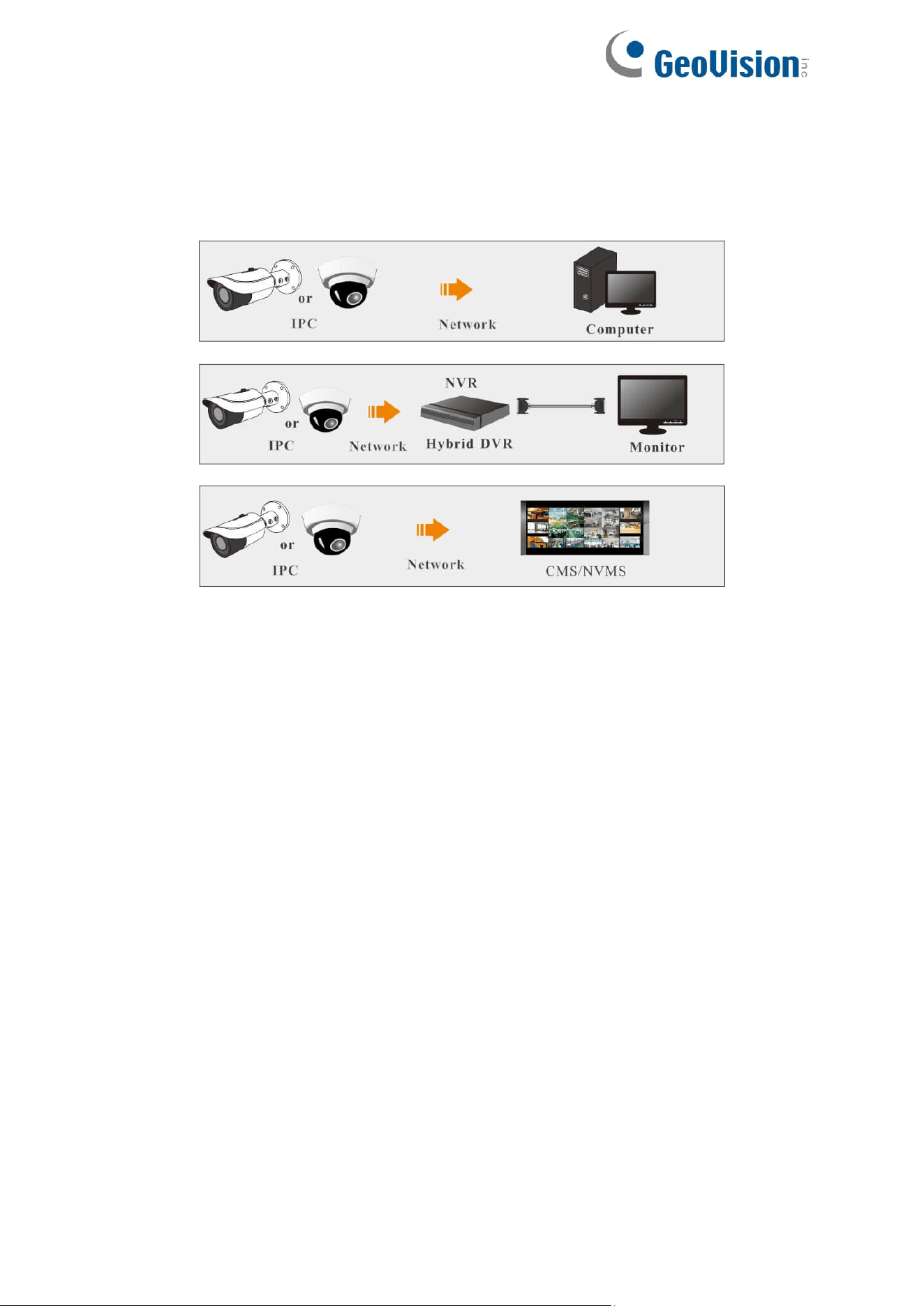
Chapter 1 Introduction
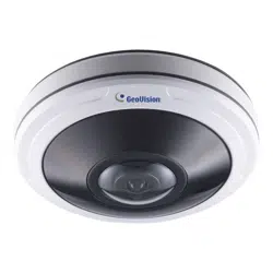
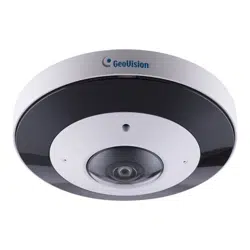
Surveillance Application

2
Chapter 2 Network Connection
System Requirement
For proper operation of the product, the following requirements should be met for your
computer.
Web browser: Edge / Chrome / Firefox / Safari
*It is recommended to use the latest version of these web browsers.
The menu display and operation of the camera may be slightly different by using the browsers
with plugins or without plugins. Installing the applicable plugins will display more functions of
the camera.
Connect the IP camera via LAN or WAN. For this example, we will use IE mode in Microsoft
Edge. The details are as follows:
3
2.1 LAN
In a LAN environment, there are two ways to access the IP camera: 1. through GV-IP Device
Utility; 2. directly through IE mode in Microsoft Edge.
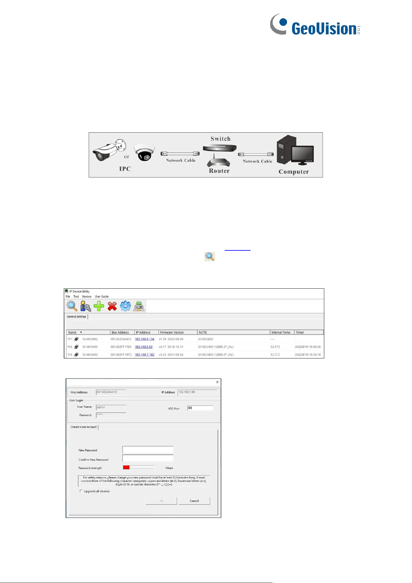
2.1.1 Access Through IP-Tool
Network connection:
By default, when the camera is connected to LAN with DHCP server, it is automatically
assigned with a dynamic IP address. Follow the steps below to look up its IP address, and use
the accessed IP address to log in from its Web interface.
1. Make sure the PC and the camera are connected to the LAN, and GV-IP Device Utility
(V8.9.8 or later) is installed on the PC from our website.
2. On GV-IP Device Utility window, click the button to search for the IP devices in the
same LAN. Click the Name or Mac Address column to sort.
3. Find the camera with its Mac Address, click on its IP address.
4. For first-time users, you are requested to create a password.

4
5. Type a new password and click OK.
6. Click on its IP address again and select Webpage to open its Web interface.
7. Type the set password on the login page and click Login.
IMPORTANT:
1. By default, the Administrator’s username is admin and cannot be modified.
2. To change the password using GV-IP Device Utility, click on the camera’s IP address,
and select Configure > Change Password. Or you can optionally change the password
on the camera’s Web interface by clicking Config→Security→User; see “Modify User”
in 4.7.1 User Configuration.
3. It is highly recommended to use the strong password for your account security. If you
want to change your password level, you can go to Config→Security
Management→Password Security interface to change the level. See “Password
Security” in 4.7.4 Security Management.
4. The security questions should be set after you log in. It is very important for you to reset
your password when you forget your password. If you forget the admin password, you
can reset the password by clicking Forget Password on the login page. For more
details, see 4.7.1 User Configuration.
5
2.1.2 Directly Access Through IE Mode in Edge
The default network settings are as shown below:
IP address: 192.168.0.10
Subnet Mask: 255.255.255.0
Gateway: 192.168.226.1
HTTP: 80
Data port: 9008
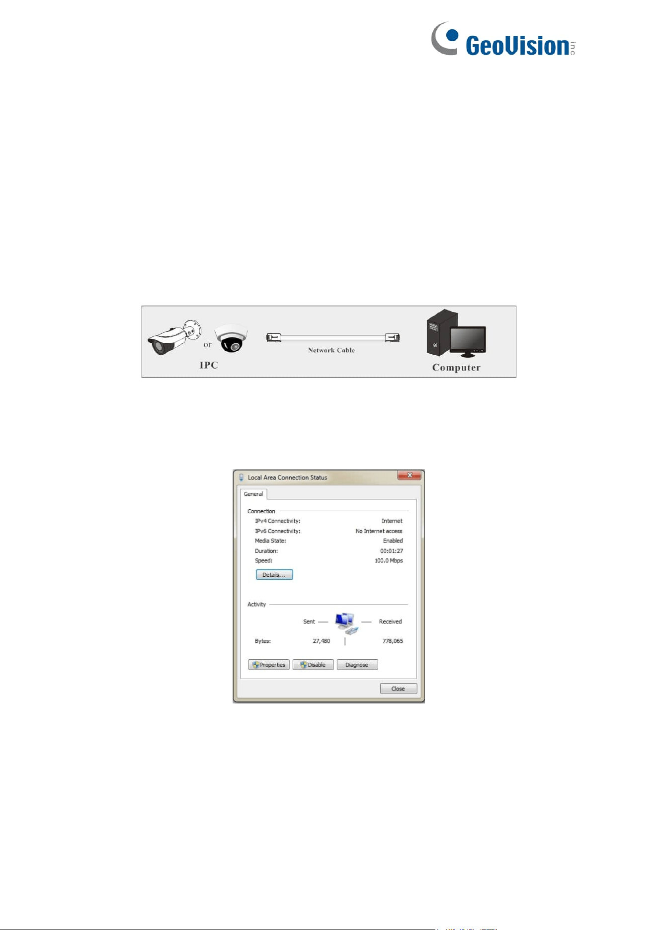
Use the above default settings when logging in the camera for the first time. Directly connect
the camera to the computer through network cable.
1. Manually set the IP address of the PC and the network segment should be the same as
the default settings of the IP camera. Open the network and share center. Click “Local
Area Connection” to pop up the following window.
2. Select “Properties” and then select internet protocol according to the actual situation (for
example: IPv4).
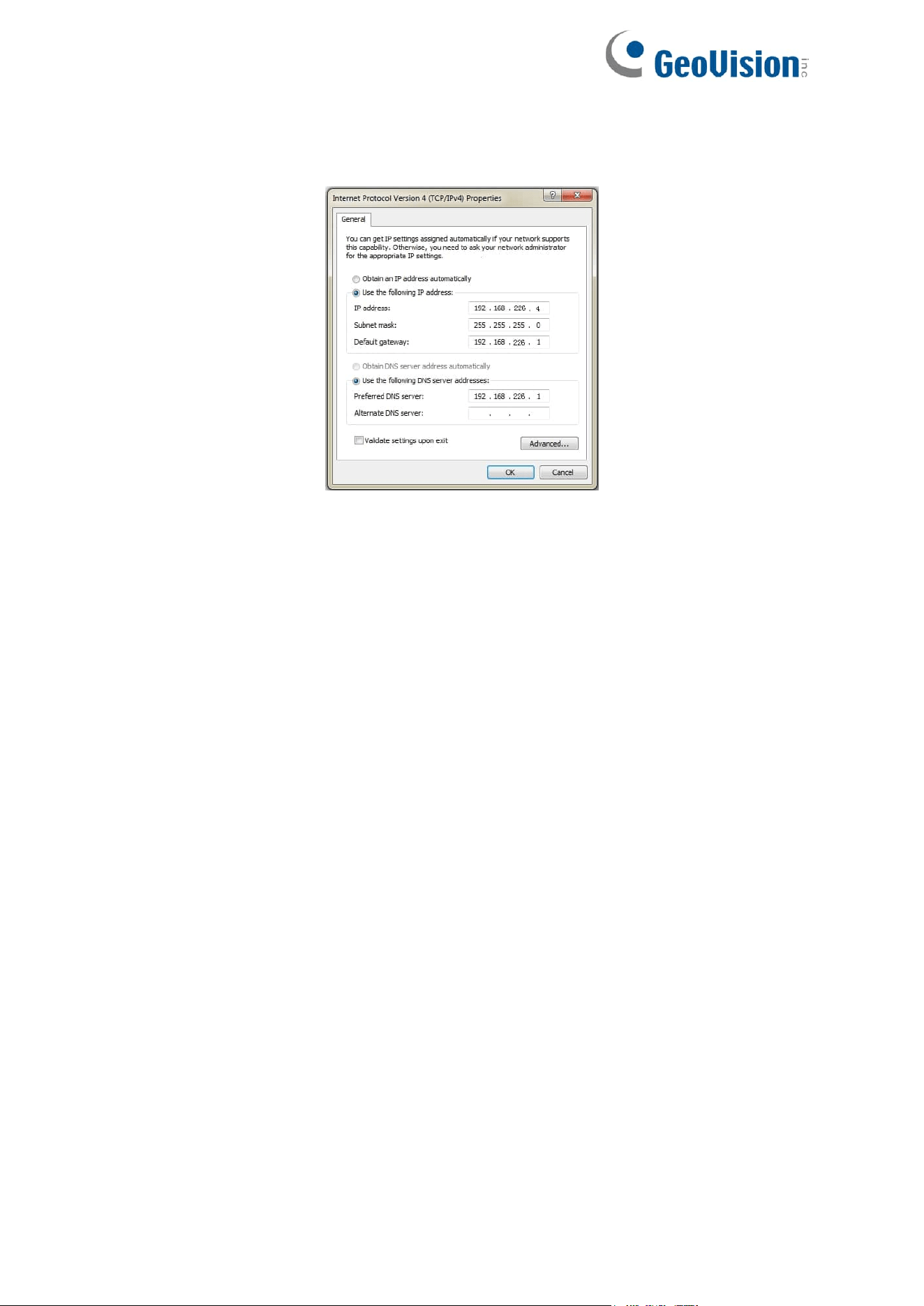
6
3. Next, click the “Properties” button to set the network of the PC.
4. Open the Web browser and enter the default address of the IP-camera.
5. Follow directions to download and install the plugins.
6. Enter the default username and password on the login page and click “Login”.
7
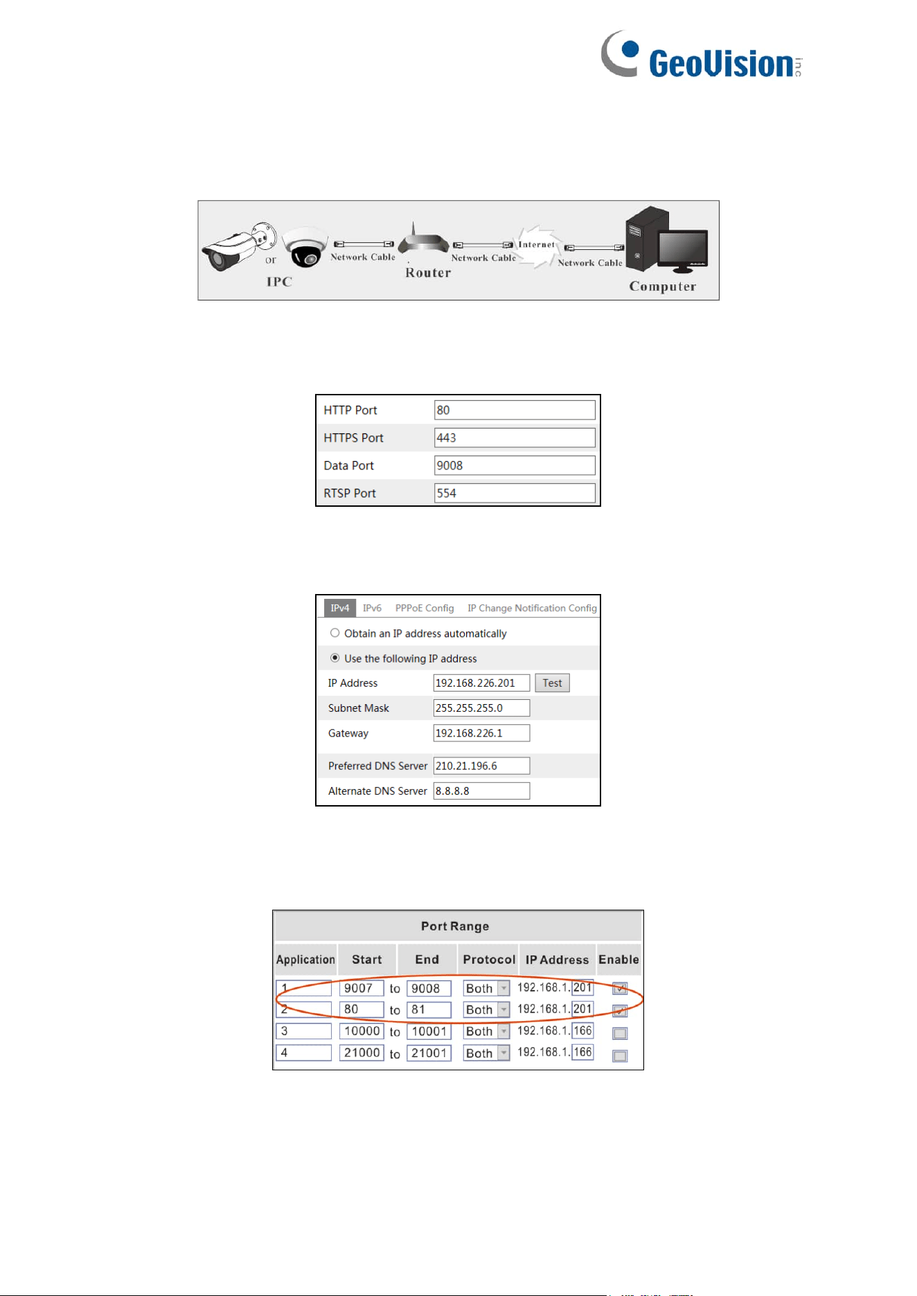
2.2 WAN
Access through the router or virtual server
1. Make sure the camera is connected to the local network and then log in the camera via
LAN and go to Config→Network→Port menu to set the port number.
Port Setup
2. Go to Config →Network→TCP/IP menu to modify the IP address.
IP Setup
3. Go to the router’s management interface through IE mode in Microsoft Edge to forward
the IP address and port of the camera in the “Virtual Server”.
Router Setup
4. Open IE mode in Microsoft Edge and enter its WAN IP and http port to access. (For
example, if the http port is changed to 81, please enter “192.198.1.201:81” in the address
bar of web browser to access).
8
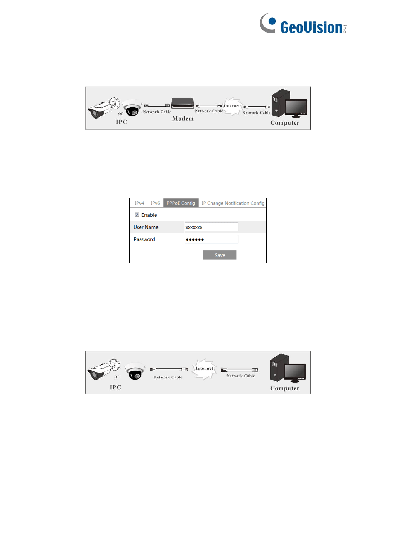
Access through PPPoE dial-up
Network connection
Access the camera through PPPoE auto dial-up. The setup steps are as follow:
1. Go to Config→Network→Port menu to set the port number.
2. Go to Config →Network→TCP/IP→PPPoE Config menu. Enable PPPoE and then enter
the user name and password from your internet service provider.
3. Go to Config →Network→DDNS menu. Before configuring the DDNS, please apply for a
domain name first. Please refer to DDNS configuration for detail information.
4. Open IE mode in Microsoft Edge and enter the domain name and http port to access.
Access through static IP
Network connection
The setup steps are as follow:
1. Go to Config→Network→Port menu to set the port number.
2. Go to Config →Network→TCP/IP menu to set the IP address. Check “Use the following
IP address” and then enter the static IP address and other parameters.
3. Open IE mode in Microsoft Edge and enter its WAN IP and http port to access.
9
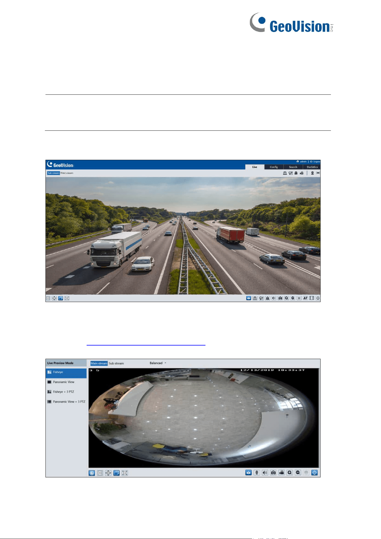
Chapter 3 Live View
After logging in, the following window will be shown.
Note: Main stream, local recording, two-way audio, and the preview mode switch
(real-time / balanced / fluent mode) are only supported in the browsers supporting
plugins.
For GV-GBL4900 / GBL4911 / GDR4900 / GEB4900 / GEBF4911 / GVD4910:
For GV-GFER4900:
Before you view the live image, please set the stream mode and installation method as
needed (see 4.1.5 Configuring Fisheye Parameters for details). In the live mode, the different
streams and live view modes can be switched as needed.
10
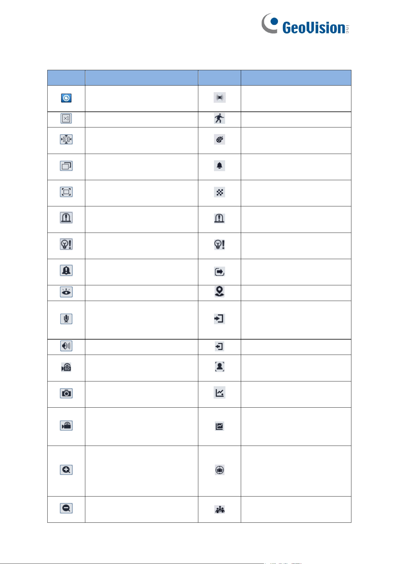
The following table is the instructions of the icons on the live view interface.
Icon
Description
Icon
Description
Select live preview mode (only
for GV-GFER6900)
Sensor alarm indicator
Original size
Motion alarm indicator
Fit correct scale
Color abnormal indicator (not
applicable to GV-GFER6900)
Adapt
Abnormal clarity indicator (not
applicable to GV-GFER6900)
Full screen
Scene change indicator (not
applicable to GV-GFER6900)
Enable/disable alarm output (not
applicable to GV-GFER6900)
Alarm output indicator (not
applicable to GV-GFER6900)
Enable/disable light alarm (only
for GV-GEBF4911)
Light alarm indicator (only for
GV-GEBF4911)
Enable/disable audio alarm (not
applicable to GV-GFER6900)
Line Crossing indicator
Start/stop live view
Region Intrusion indicator
Start/stop two-way audio (only
available in the browsers
supporting plugins)
Region Entrance indicator
Enable/disable audio
Region Exiting indicator
SD card recording indicator
Face detection indicator (not
applicable to GV-GFER6900)
Snapshot
Target Counting by Line
indicator
Start/stop local recording (only
available in the browsers
supporting plugins)
Target Counting by Area
indicator (not applicable to
GV-GFER6900)
Zoom in
Object detection indicator
(object Abandoned/Missing)
(not applicable to
GV-GFER6900)
Zoom out
Crowd density indicator (only
for GV-GFER6900)
11
Note:
1. Those smart alarm indicators will flash only when the camera supports those functions
and the corresponding events are enabled.
2. After clicking the audio alarm icon, the sound warning will be triggered according to the
set warning times (you can set the warning times by clicking Config→Alarm→Audio
Alarm). Click this icon again. After the current warning voice is completely sounded, it
will stop.
3. After clicking the light alarm icon, the red-blue light will flash alternatively according to
the set flashing time (you can set the flashing time by clicking Config→Alarm→Light
Alarm). Click this icon again to stop flashing.
AZ Control
Click AZ control button to show AZ control panel. The descriptions of the control panel are as
follows:
Icon
Description
Icon
Description
Zoom -
Zoom +
Focus -
Focus +
One key focus (used when image is out of focus after
manual adjustment)
Note: The AZ Control function is only applicable to GV-GEBF4911.
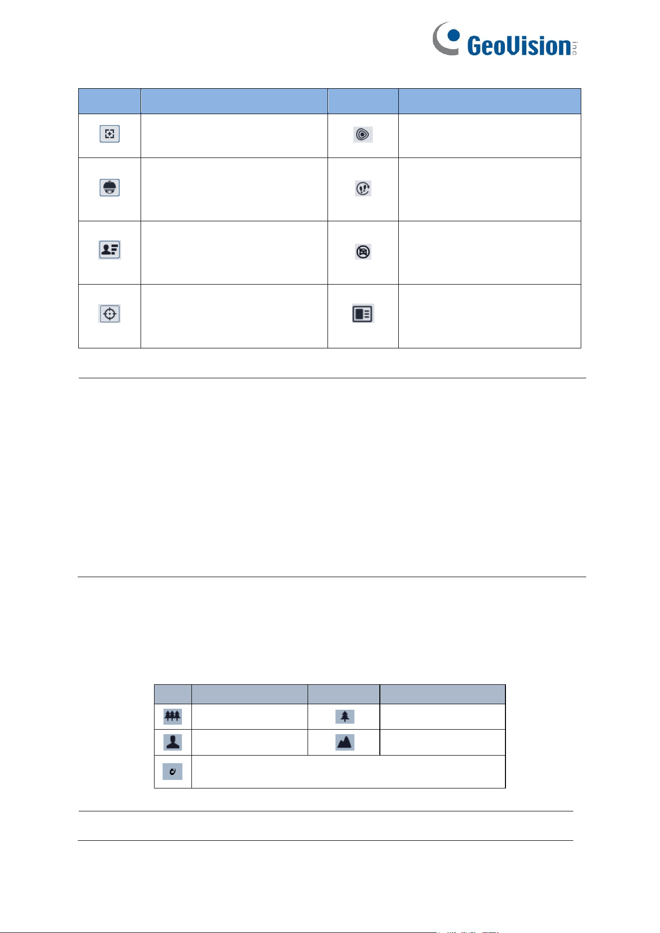
Icon
Description
Icon
Description
AZ control (only for
GV-GEBF4911)
Heat map indicator
PTZ control
Loitering detection indicator
(not applicable to
GV-GEBF4911 / GFER6900)
Face Detection (not applicable
to GV-GFER6900)
Illegal parking detection
indicator (not applicable to
GV-GEBF4911 / GFER6900)
Rule information display
Video metadata extraction
indicator (not applicable to
GV-GFER6900)
12
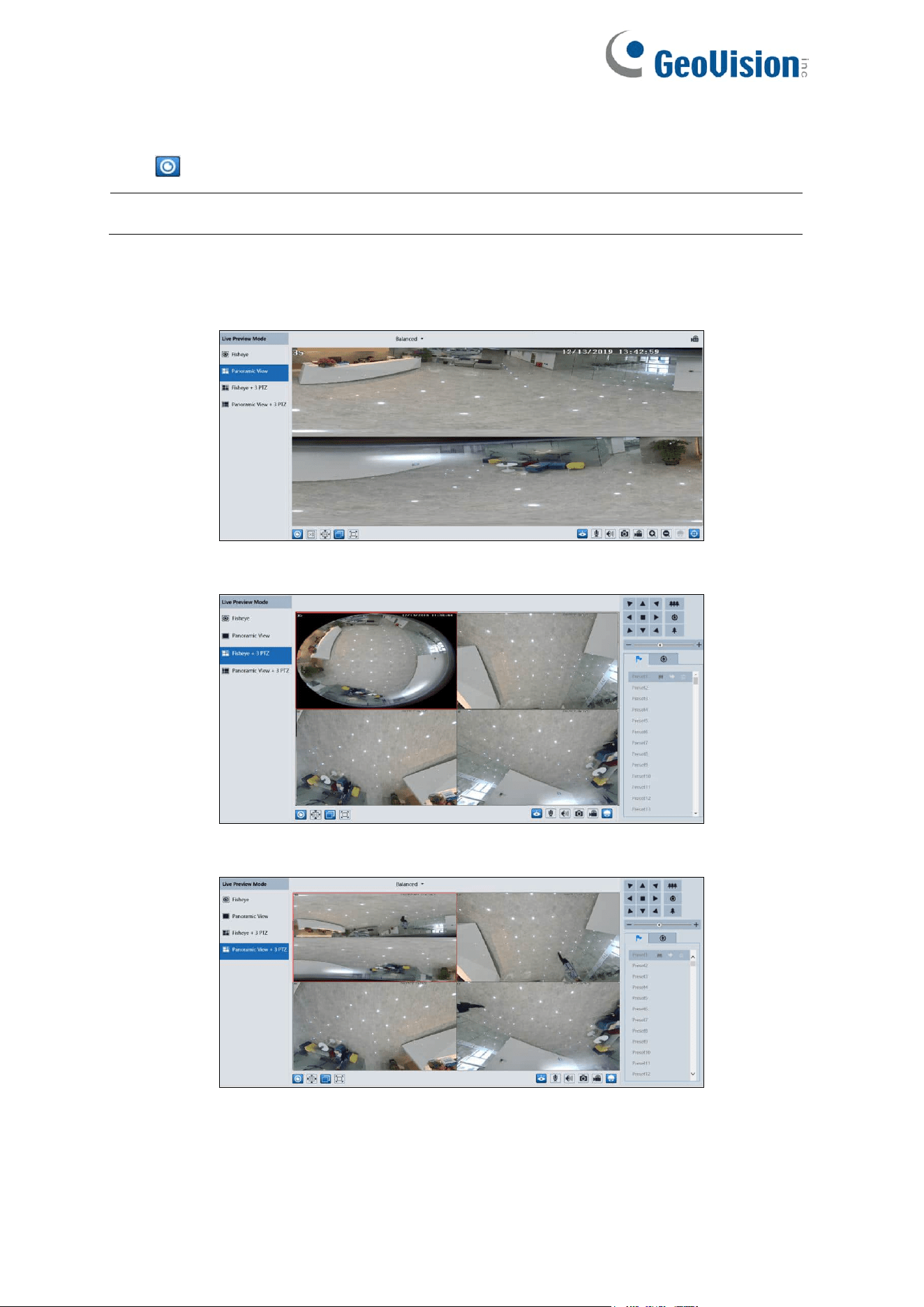
Live Preview Mode
Click to select the live view mode.
Note: The Live Preview Mode menu is only applicable to GV-GFER6900.
Fisheye view mode: See the picture as shown above.
Panoramic view mode:
Fisheye+ 3PTZ view mode:
Panoramic + 3PTZ view mode:
13
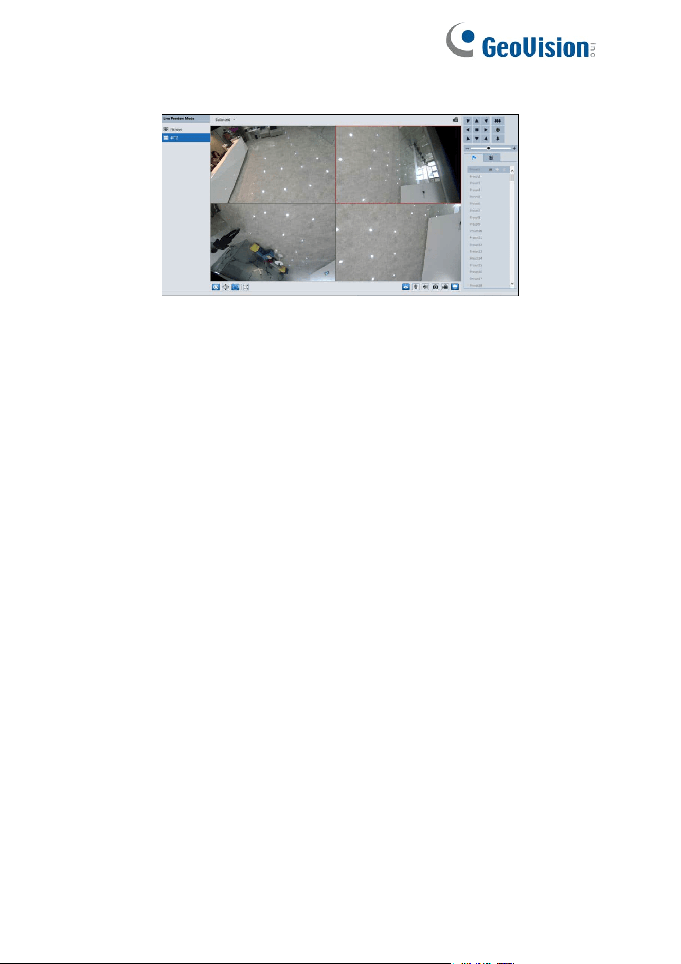
4PTZ view mode: Requires switching the stream mode in the Fisheye Parameters settings
4PTZ fusion view mode: Displays a complete image formed by 4 smaller windows, none of
which can be controlled via the PTZ panel.
In Panoramic + 3PTZ view mode, Fisheye + 3PTZ view mode, or 4PTZ view mode, select a
PTZ window and view the image from every direction by controlling the PTZ panel.
14
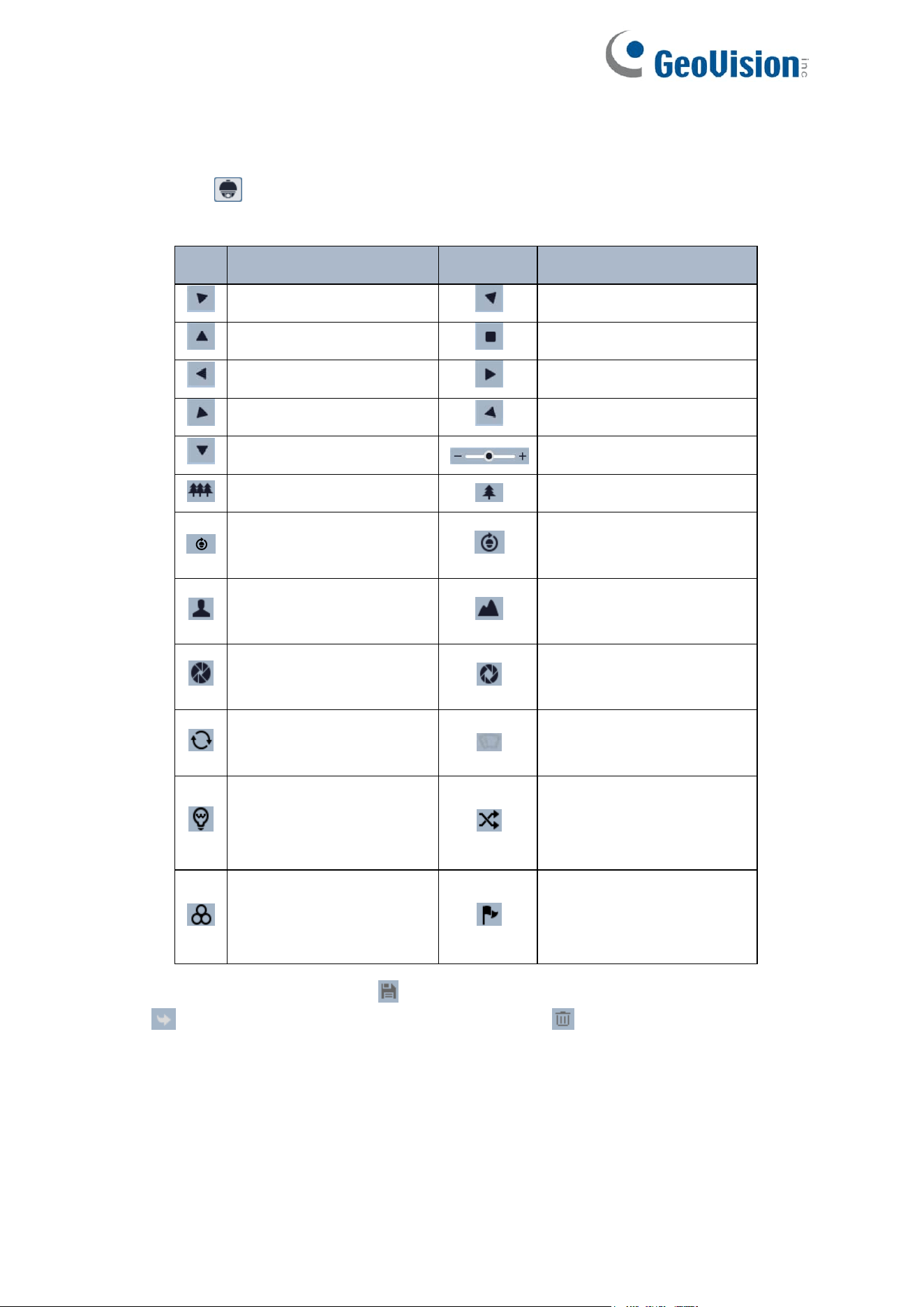
PTZ Control
Some cameras can be installed in a compatible external PTZ enclosure through RS485. Click
the PTZ icon to reveal the PTZ control panel. The descriptions of the control panel are as
follows:
Select and set the preset and click to save the position of the preset. Select preset and
click to call the preset. Select the set preset and click to delete it.
Icon
Description
Icon
Description
Move upper left direction
Move upper right direction
Move up
Stop movement
Move left
Move right
Move lower left direction
Move lower right direction
Move down
Speed adjustment
Zoom out
Zoom in
Automatic cruise (only for
GV-GFER6900)
Create and call cruise
(only for GV-GFER6900)
Focus – (not applicable to
GV-GFER6900)
Focus + (not applicable to
GV-GFER6900)
Iris - (not applicable to
GV-GFER6900)
Iris + (not applicable to
GV-GFER6900)
Auto scan (not applicable
to GV-GFER6900)
Wiper (not applicable to
GV-GFER6900)
Light (not applicable to
GV-GFER6900)
Random scan (not
applicable to
GV-GFER6900)
Group scan (not
applicable to
GV-GFER6900)
Preset
15
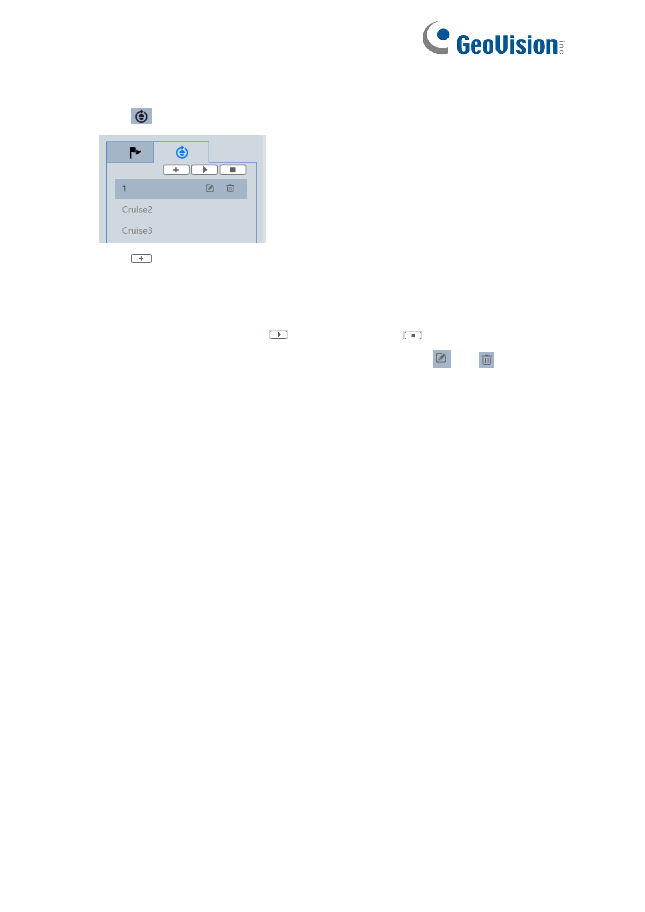
To create a cruise (only for GV-GFER6900):
1. Click as shown below.
2. Click to create a cruise. In the cruise creation window, enter the cruise name and
then click “Add preset”.
3. In the preset adding window, select the preset name and time. Click “OK” to add this
preset. After the presets are added to the cruise, click “OK” to save the settings.
4. Select the cruise and then click to start cruise. Click to stop cruise.
5. The added cruise also can be modified and deleted by clicking or .
16
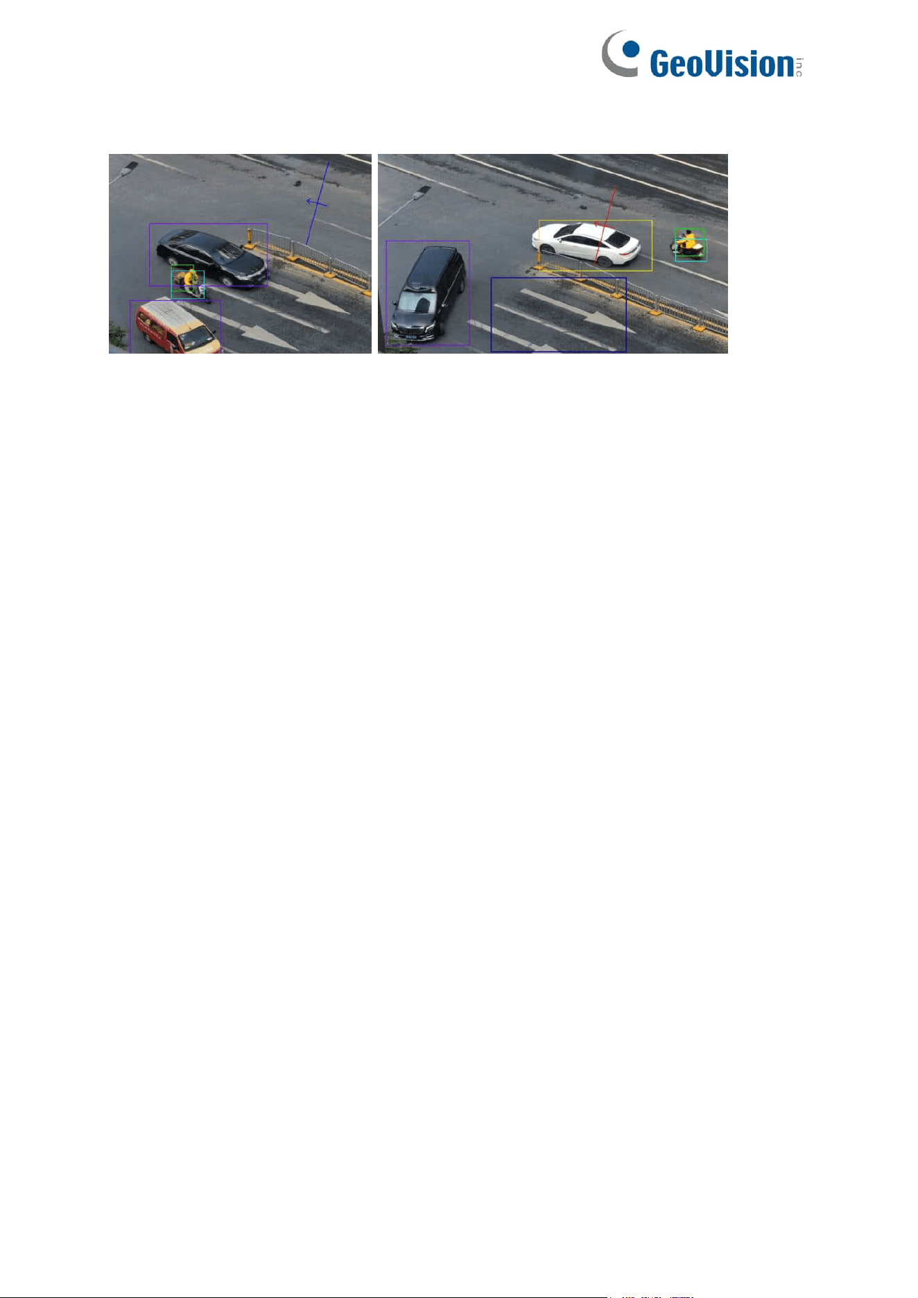
Rule Information
Color Descriptions of Target Recognition box:
Green box: detect human
Purple box: detect motor vehicle
Light blue box: detect non-motor vehicle (motorcycle/bicycle)
Rule line or area color display:
Rule line or area: blue
Rule line or area after an event is triggered: turn from blue to red
17
Chapter 4 Network Camera Configuration
In the Webcam client, choose “Config” to go to the configuration interface.
Note: Wherever applicable, click the “Save” button to save the settings.
4.1 System Configuration
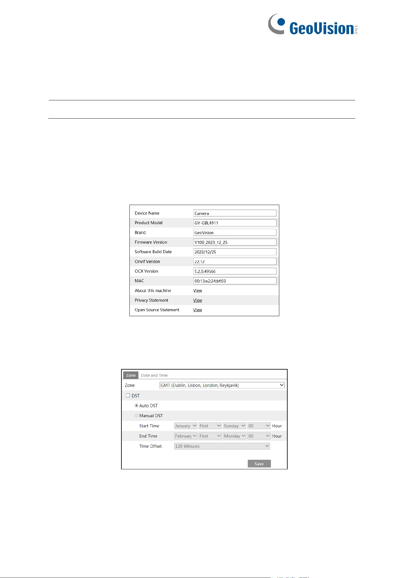
4.1.1 Basic Information
In the “Basic Information” interface, the system information of the device is listed.
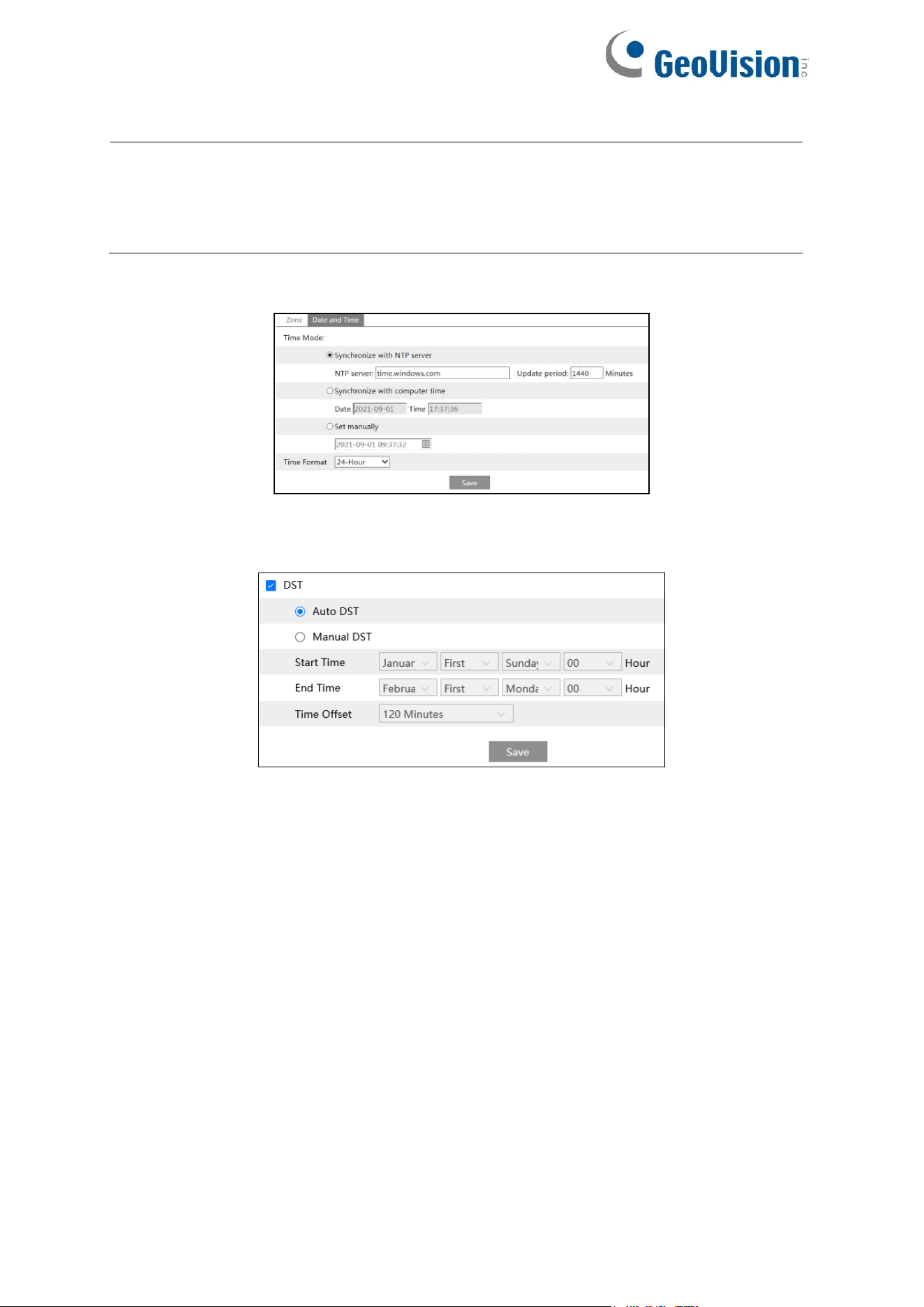
4.1.2 Date and Time
Go to Config→System→Date and Time. Please refer to the following interface.
Select the time zone and DST as required.
18
Note: The time zone of the camera and the computer must be the same. It is
recommended to modify the time zone of the camera according to the time zone of the
computer. If the time zone of the computer is modified, the current web client needs to
be closed. Then re-open it and log in again.
For GV-GEBF4911: Click the “Date and Time” tab to set the time mode and time format.
For GV-GBL4900 / GBL4911 / GDR4900 / GEB4900 / GFER6900 / GVD4910:
Click the “Summer Time” tab to set DST (Daylight Saving Time) as needed.
19
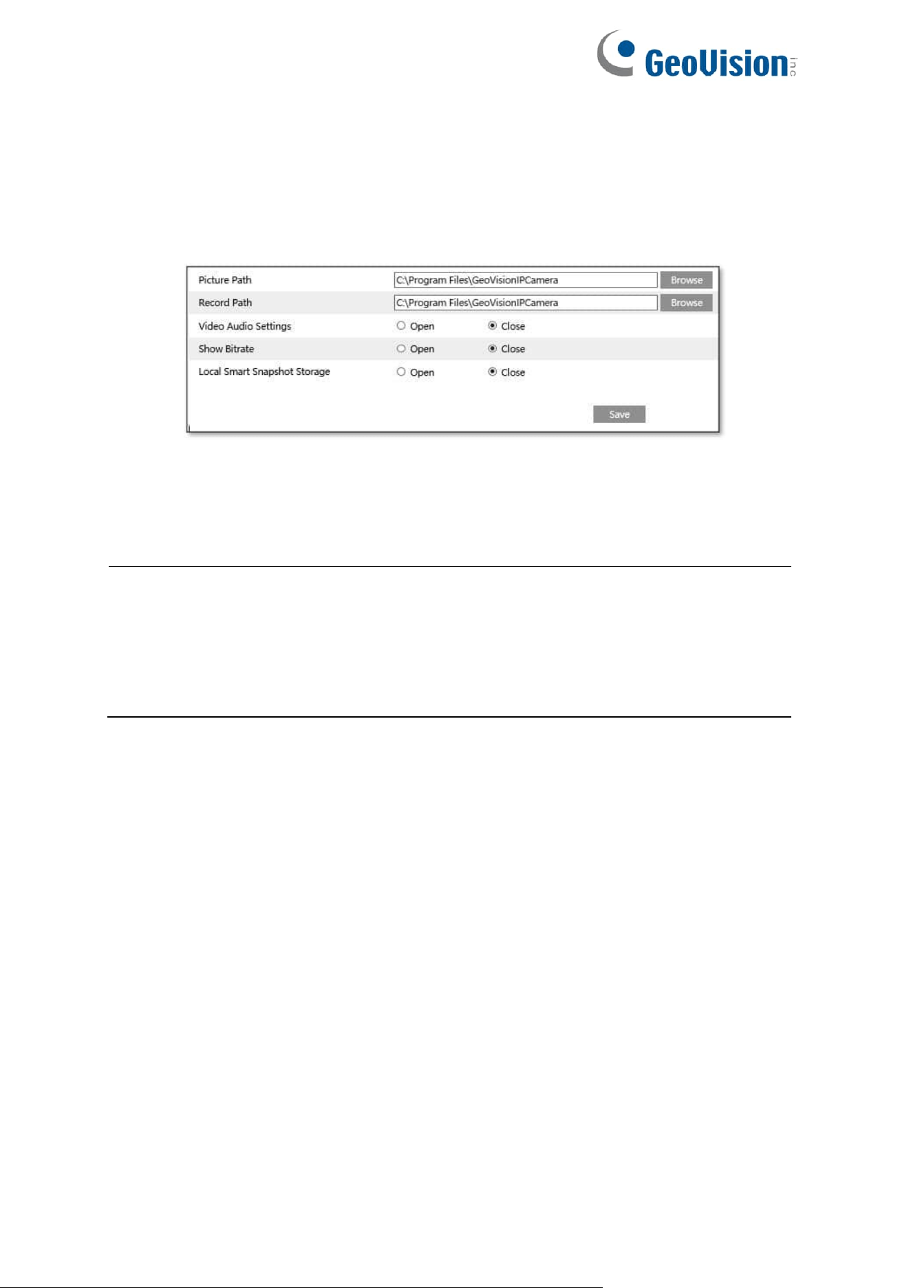
4.1.3 Local Config
Go to Config→System→Local Config to set up the storage path of captured pictures and
recorded videos on the local PC. There is also an option to enable or disable the bitrate
display in the recorded files.
Additionally, “Local smart snapshot storage” can be enabled or disabled here. If enabled, the
captured pictures triggered by smart events (like line crossing detection, region entrance, etc.)
will be saved to the local PC.
Note:
1. If you are using the browsers not supporting plugins or your computer has no graphics
card, low-efficient mode is suggested.
2. In the browsers not supporting plugins, only Show Bitrate can be set in the above
interface.
20
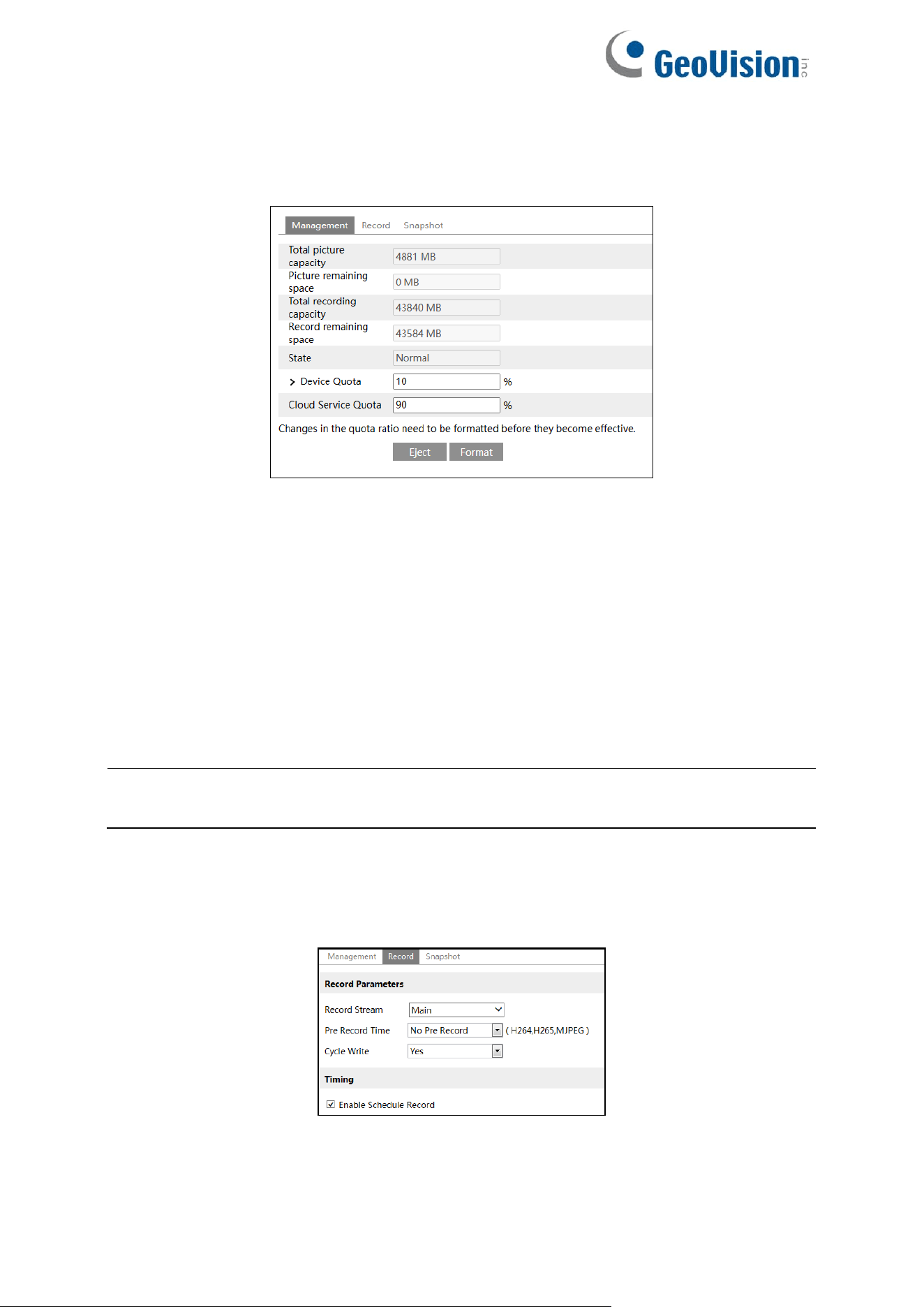
4.1.4 Storage
Go to Config→System→Storage to go to the interface as shown below.
4.1.4.1 SD Card Management
Click the “Format” button to format the SD card. All data will be cleared by clicking this button.
Click the “Eject” button to stop writing data to SD card. Then the SD card can be ejected
safely.
Device Quota: Set the capacity proportion of captured pictures/record files on the SD card.
Cloud Service Quota: Set the capacity proportion of captured pictures/record files uploaded
onto GV-Cloud VMS.
Note: For details on connecting to GV-Cloud VMS, see 7. Connecting to GV-Cloud VMS in
GV-IP Cloud Cameras Quick Start Guide.
4.1.4.2 Schedule Recording Settings
1. Go to Config→System→Storage→Record to go to the interface as shown below.
2. Set record stream, pre-record time, cycle writing.
Pre Record Time: Set the time to record before the actual recording begins.
21
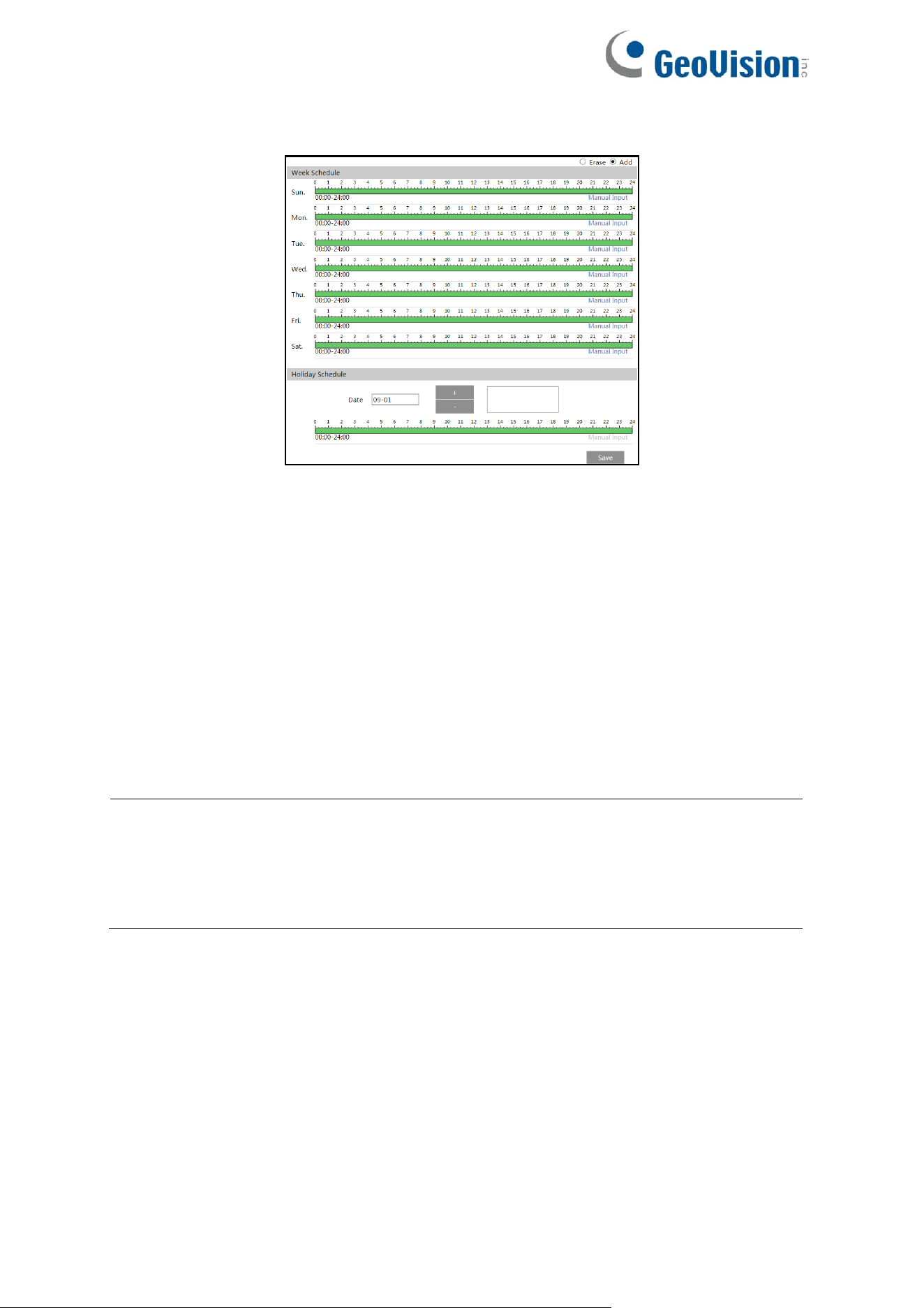
3. Set schedule recording. Check “Enable Schedule Record” and set the schedule.
Weekly Schedule
Set the alarm time from Monday to Sunday for a single week. Each day is divided in one-hour
increments. Green means scheduled. Blank means unscheduled.
“Add”: Add the schedule for a special day. Drag the mouse to set the time on the timeline.
“Erase”: Delete the schedule. Drag the mouse to erase the time on the timeline.
Manual Input: Click it for a specific day to enter specific start and end times. This adds more
granularities (minutes).
Holiday Schedule
Set the alarm time for alarm a special day, such as a holiday.
Note:
1. The Schedule Recording settings, including Record Parameters, are for playback on
the camera’s Web interface. They will not apply to GV-Center V2 or GV-Cloud VMS.
2. Holiday schedule takes priority over weekly schedule.
22
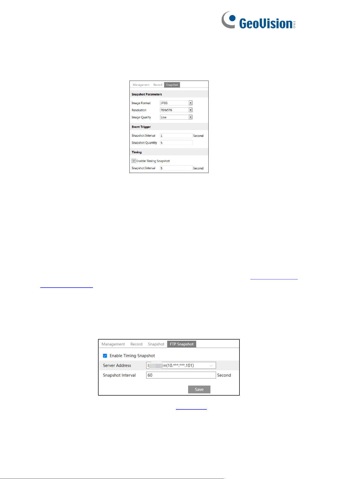
4.1.4.3 Snapshot Settings
Go to Config→System→Storage→Snapshot to go to the interface as shown below.
Set the format, resolution and quality of the image saved on the SD card and the snapshot
interval and quantity and the timing snapshot here.
Snapshot Quantity: The number you set here is the maximum quantity of snapshots. The
actual quantity of snapshots may be less than this number. Supposing the occurrence time of
an alarm event is less than the time of capturing pictures, the actual quantity of snapshots is
less than the set quantity of snapshots.
Snapshot Timing
Check the box for “Enable Timing Snapshot” first and set the snapshot interval and schedule.
The setup steps of schedule are the same as the schedule recording (See 4.1.4.2 Schedule
Recording Settings).
4.1.4.4 FTP Snapshot
If enabled, the system will upload snapshots to the FTP server according to the time interval.
Server Address: select the set FTP server. See 4.6.10 FTP for the FTP server setting.
23
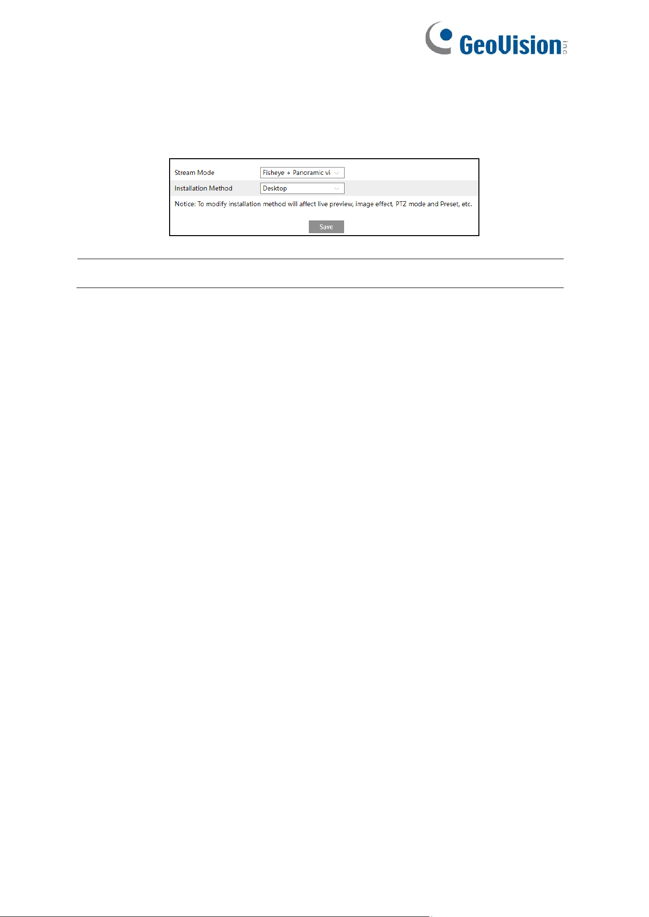
4.1.5 Configuring Fisheye Parameters
Before viewing the live image, please go to Config→System→Fisheye Parameters menu to
set the stream mode and installation method.
Note: The Fisheye Parameters menu is only applicable to GV-GFER6900.
Stream Mode: Fisheye, Panoramic View, Fisheye + Panoramic view + 3PTZ, Fisheye +
4PTZ, and Fisheye + 4PTZ Fusion modes are optional.
Installation Method: Wall, Desktop, and Ceiling installation methods are optional. Select the
installation mode according to the actual way of installation.
24
4.2 Image Configuration
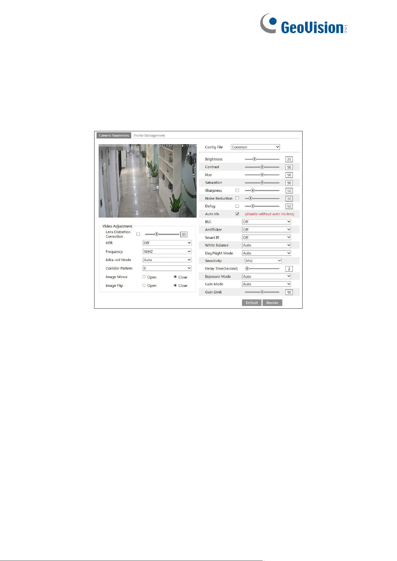
4.2.1 Display Configuration
Go to Image→Display Settings interface as shown below. The image’s brightness, contrast,
hue and saturation and so on for common, day and night mode can be set up separately. The
image effect can be quickly seen by switching the configuration file.
Brightness: Set the brightness level of the camera’s image.
Contrast: Set the color difference between the brightest and darkest parts.
Hue: Set the total color degree of the image.
Saturation: Set the degree of color purity. The purer the color, the brighter the image is.
Sharpness: Set the resolution level of the image plane and the sharpness level of the image
edge.
Noise Reduction: Decrease the noise and make the image more thorough. Increasing the
value will make the noise reduction effect better but it will reduce the image resolution.
Defog: Activating this function and setting an appropriate value as needed in foggy, dusty,
smoggy, or rainy environment to get clear images.
Auto Iris: If your camera is equipped with auto Iris lens, please enable it.
Backlight Compensation (BLC):
⚫ Off: Disables the backlight compensation function. It is the default mode.
⚫ HWDR: WDR can adjust the camera to provide a better image when there are both
very bright and very dark areas simultaneously in the field of the view by lowering the
brightness of the bright area and increasing the brightness of the dark area.

25
⚫ HLC: Lowers the brightness of the entire image by suppressing the brightness of the
image’s bright area and reducing the size of the halo area.
⚫ BLC: If enabled, the auto exposure will activate according to the scene so that the
object of the image in the darkest area will be seen clearly.
Recording will be stopped for a few seconds while the mode is changing from non-WDR to
WDR mode.
Antiflicker:
⚫ Off: disables the anti-flicker function. This is used mostly in outdoor installations.
⚫ 50Hz: reduces flicker in 50Hz lighting conditions.
⚫ 60Hz: reduces flicker in 60Hz lighting conditions.
Smart IR: Choose “ON” or “OFF”. This function can effectively avoid image overexposure so
as to make the image more realistic. The higher the level is, the more overexposure
compensation will be given.
White Balance: Adjust the color temperature according to the environment automatically.
If “Infrared light” is selected for Illumination Mode, “Smart IR” and “Day/Night Mode” can be
configured.
Day/Night Mode: Choose “Auto”, “Day”, “Night” or “Timing”.
If “Timing” is selected, you need to set daytime and night time. For example: if “Daytime” is set
to “7:00”, the camera will switch to Day mode at 7:00; if “Night time” is set to “17:00”, the
camera will switch from Day mode to Night mode at 17:00.
Shutter Mode (for GV-GEBF4911): Choose “Auto” or “Manual”. If manual is chosen, the
digital shutter speed can be adjusted.
Shutter (for GV-GBL4900 / GBL4911 / GDR4900 / GEB4900 / GFER6900 / GVD4910): Set
the upper limit of the effective exposure time. The exposure time will be automatically adjusted
(within the set shutter limit value) according to the actual situation.
Gain Mode (for GV-GEBF4911): Choose “Auto” or “Manual”. If “Auto” is selected, the gain
value will be automatically adjusted (within the set gain limit value) according to the actual
situation. If “Manual” is selected, the gain value shall be set manually. The higher the value is,
the brighter the image is.
Gain (for GV-GBL4900 / GBL4911 / GDR4900 / GEB4900 / GFER6900 / GVD4910): Set the
upper limit of the gain. The gain value will be automatically adjusted (within the set gain limit
value) according to the actual situation.
26
Lens Distortion Correction (not applicable to GV-GFER6900): When the image appears
distortion to some extent, please enable this function and adjust the level according to the
actual scene to correct the distortion.
Frequency: 50 Hz and 60 Hz can be optional.
Corridor Pattern (not applicable to GV-GFER6900): Corridor viewing modes can be used
for situations such as long hallways. 0, 90, 180 and 270 are available. The default value is 0.
Image Mirror: Turn the current video image horizontally.
Image Flip: Turn the current video image vertically.
Illumination Mode (for GV-GEBF4911): Choose “White light”, “Infrared light” or “Smart
supplement light” as needed.
Smart supplement light (for GV-GEBF4911): If selected, in low ambient light, the system will
automatically turn on the IR light or white light. Once there are people appearing in the
detection area, it will automatically switch to white light. When no people are detected, it will
switch to IR light.
If “White Light” is selected, “Overexposure control” and “white light mode” can be configured.
Overexposure Control (for GV-GEBF4911): Choose “OFF”, “Low”, “Mid” or “High”. This
function can automatically adjust the exposure parameter according to the actual effect of the
image, effectively avoiding detail missing caused by image overexposure, so that the image
will be more vivid. Please set it as needed.
White Light Mode: Choose “Off”, “Auto” or “Manual”. Please select it as needed.
Infrared Mode: Choose “Auto”, “ON” or “OFF”.
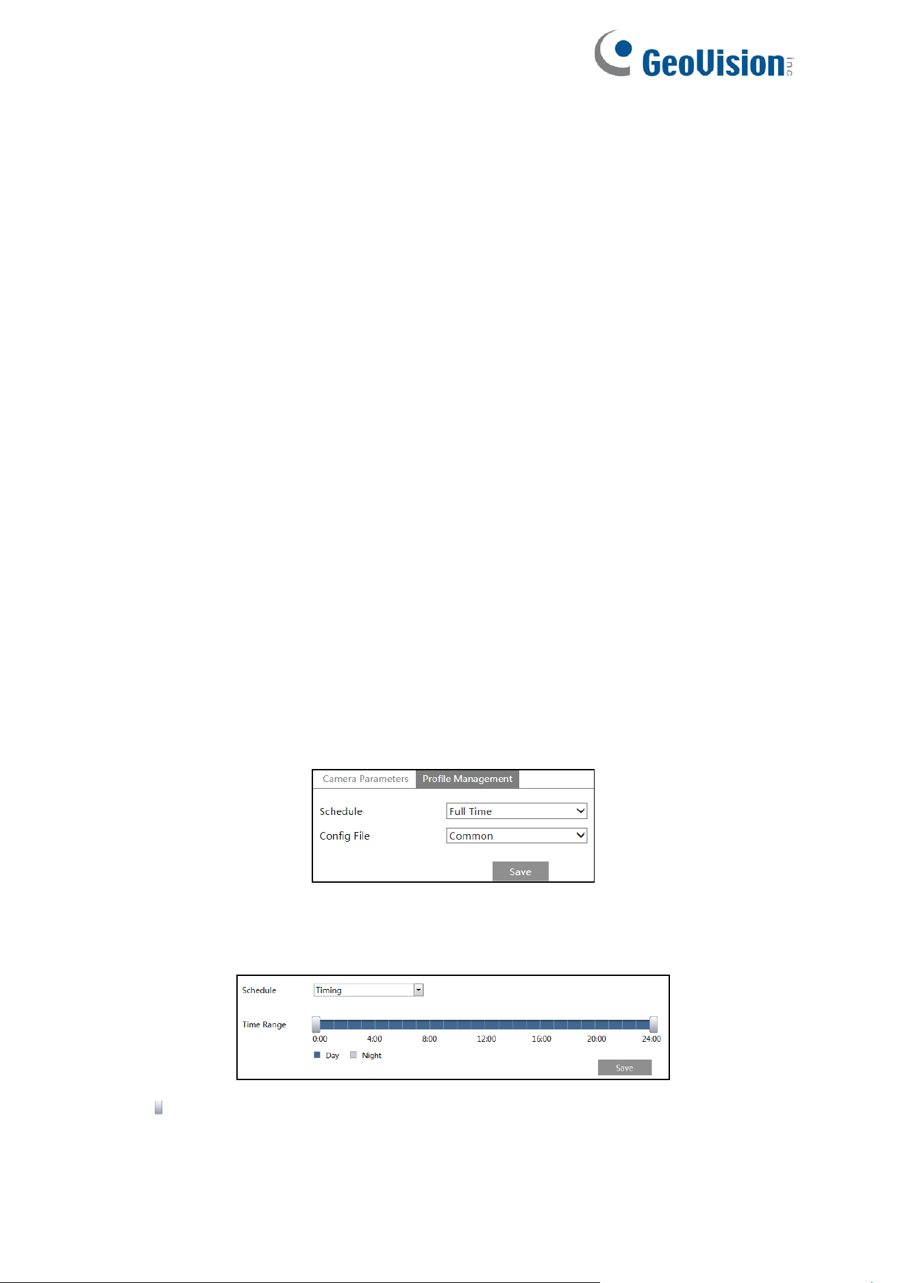
Schedule Settings of Image Parameters
Click the “Profile Management” tab as shown below.
Set full time schedule for common, day, night mode and specified time schedule for day and
night. Choose “Timing” in the drop-down box of schedule as shown below.
Drag “ ” icons to set the time of day and night. Blue means day time and blank means night
time. If the current mode of camera parameters is set to schedule, the image configuration
mode will automatically switch between day and night according to the schedule.
27
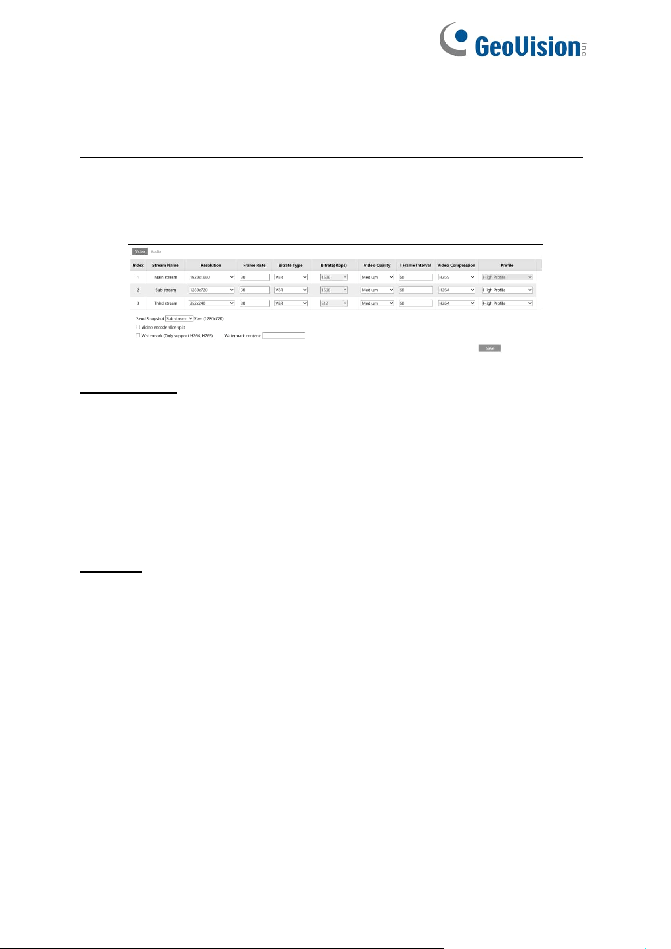
4.2.2 Video / Audio Configuration
Go to Image→Video / Audio interface as shown below. In this interface, set the resolution,
frame rate, bitrate type, video quality and so on subject to the actual network condition.
Note: The video stream parameters of different camera series may be different. The
following pictures and descriptions are for reference only. The real camera interface
shall prevail.
For GV-FER6900
You can select streams for different channels.
IP Channel 1: Fisheye view channel, 2 streams can be set. Please set them according to the
actual network condition.
IP Channel 2: Panoramic view channel, main stream can be set. Please set them according to
the actual network condition.
IP Channel 3/4/5: PTZ view channel, main stream can be set for each channel. Please set
them according to the actual network condition.
All Models
Three video streams can be adjustable.
Resolution: The size of image.
Frame rate: The higher the frame rate, the smoother the video is.
Bitrate type: CBR and VBR are optional. Bitrate is related to image quality. CBR means that
no matter how much change is seen in the video scene, the compression bitrate will be kept
constant. VBR means that the compression bitrate will be adjusted according to scene
changes. For example, for scenes that do not have much movement, the bitrate will be kept at
a lower value. This can help optimize the network bandwidth usage.
Bitrate: It can be adjusted when the bitrate type is set to CBR. The higher the bitrate, the
better the image quality will be.
Video Quality: It can be adjusted when the bitrate type is set to VBR. The higher the image
quality, the more bitrate will be required.
I Frame interval: It determines how many frames are allowed between a “group of pictures”.
When a new scene begins in a video, until that scene ends, the entire group of frames (or
pictures) can be considered as a group of pictures. If there is not much movement in the
scene, setting the value higher than the frame rate is fine, potentially resulting in less
28
bandwidth usage. However, if the value is set too high, and there is a high frequency of
movement in the video, there is a risk of frame skipping.
Video Compression: MJPEG, H264+, H264, H265 or H265+ are applicable. MJPEG is not
available for main stream. If H.265 / H.265+is chosen, make sure the client system is able to
decode H.265 / H.265+. Compared to H.265, H.265+ saves more storage space with the
same maximum bitrate in most scenes. Compared to H.264, H.265 reduces the transmission
bitrate under the same resolution, frame rate and image quality.
Note: For the browsers not supporting plugins, MJPEG is not recommended (if the sub /
third stream and MJPEG are selected, no image will be output).
Profile: For H.264. Baseline, main and high profiles are selectable.
Send Snapshot: Set the snapshot stream.
Video encode slice split: If this function is enabled, smooth image can be gotten even
though using the low-performance PC.
Watermark: When playing back the local recorded video in the search interface, the
watermark can be displayed. To enable it, check the watermark box and enter the watermark
text.
Note: When the camera is connected to GV-Cloud VMS, the resolution and bitrate values
will be grayed out and cannot be modified. For details on GV-Cloud VMS connection, see
4.5.1 GV-Cloud.
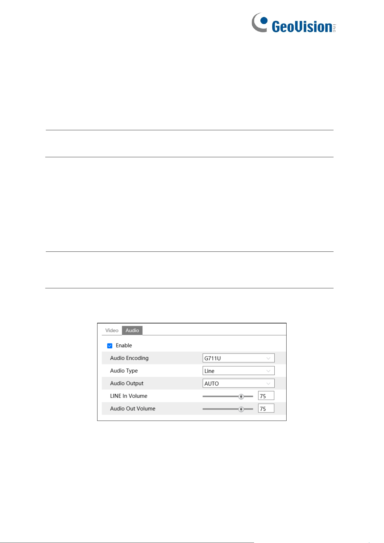
Click the “Audio” tab to go to the interface as shown below.
Only the models with the built-in MIC support this function.
Audio Encoding: G711A and G711U are selectable.
Audio Type: Line or MIC can be optional.
LINE IN/MIC IN Volume: LINE IN Volume can be set here. If MIC is selected, MIC IN volume
can be set.

29
Audio Output (not applicable to GV-GFER6900): Talkback, warning or auto can be optional.
If “Talkback” is selected, the audio output will be used to output sound for two-way talk. If
“Warning” is selected, the audio output will be used to output the pre-defined audio alarm. If
“Auto” is selected, the system will output sound for two-way talk or warning voice as needed.
But when it is warning and two-way audio is being enabled simultaneously, two-way audio will
be output first.
Speaker (for GV-GEBF4911): Talkback, warning or auto can be optional. If “Talkback” is
selected, the built-in speaker will be used to output sound for two-way talk. If “Warning” is
selected, the built-in speaker will be used to output the pre-defined audio alarm. If “Auto” is
selected, the system will output sound for two-way talk or warning voice as needed. But when
it is warning and two-way audio is being enabled simultaneously, two-way audio will be output
first.
Audio Out Volume: This function is available for the model with audio out interface.
30
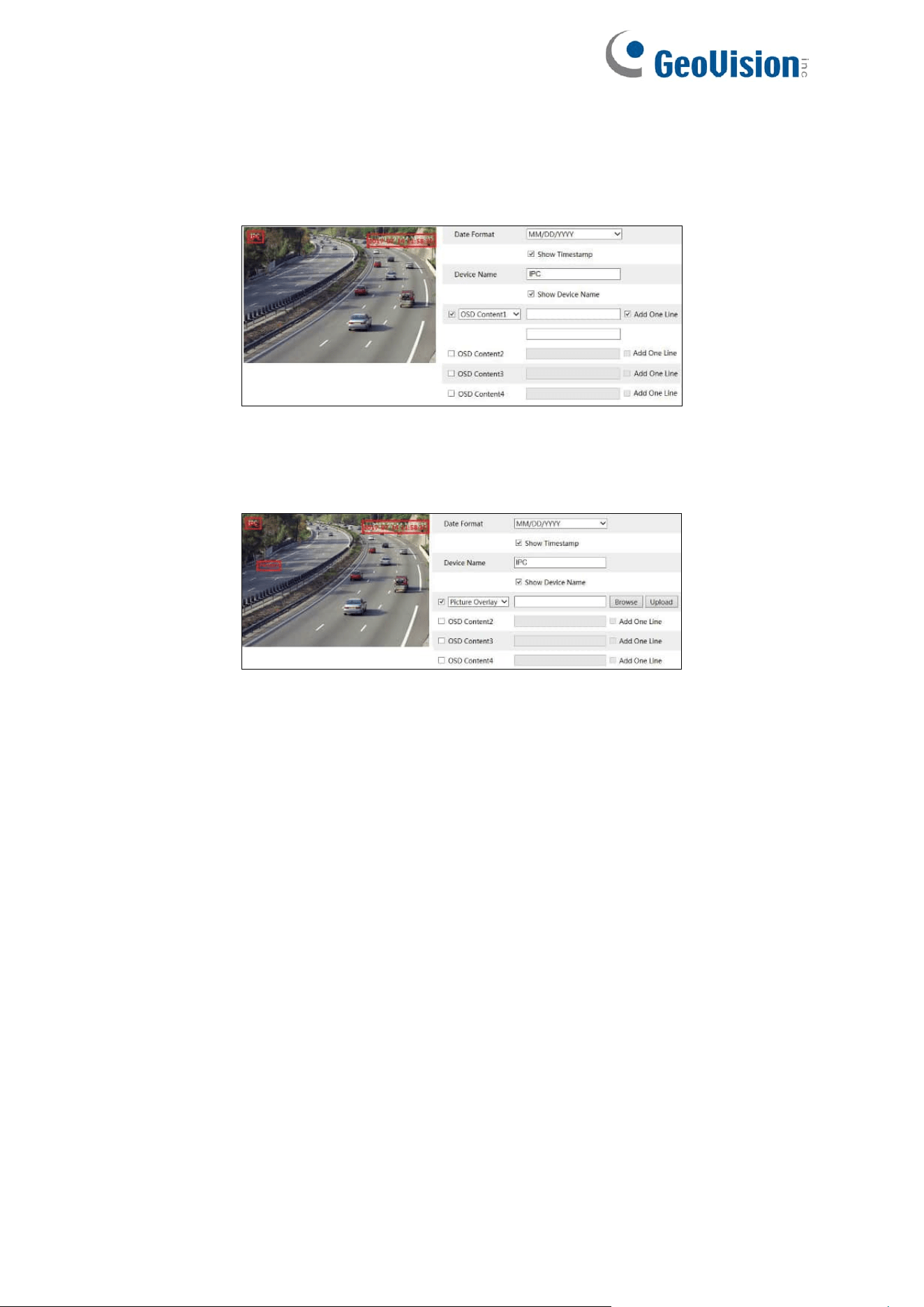
4.2.3 OSD Configuration
Go to Image→OSD interface as shown below.
For GV-GEBF4911
Set time stamp, device name, OSD content and picture overlap here. After enabling the
corresponding display and entering the content, drag them to change their position. Then click
the “Save” button to save the settings.
Picture Overlap Settings:
Check “OSD Content1”, choose “Picture Overlay” and click “Browse” to select the overlap
picture. Then click “Upload” to upload the overlap picture. The pixel of the image shall not
exceed 200*200, or it cannot be uploaded.
31
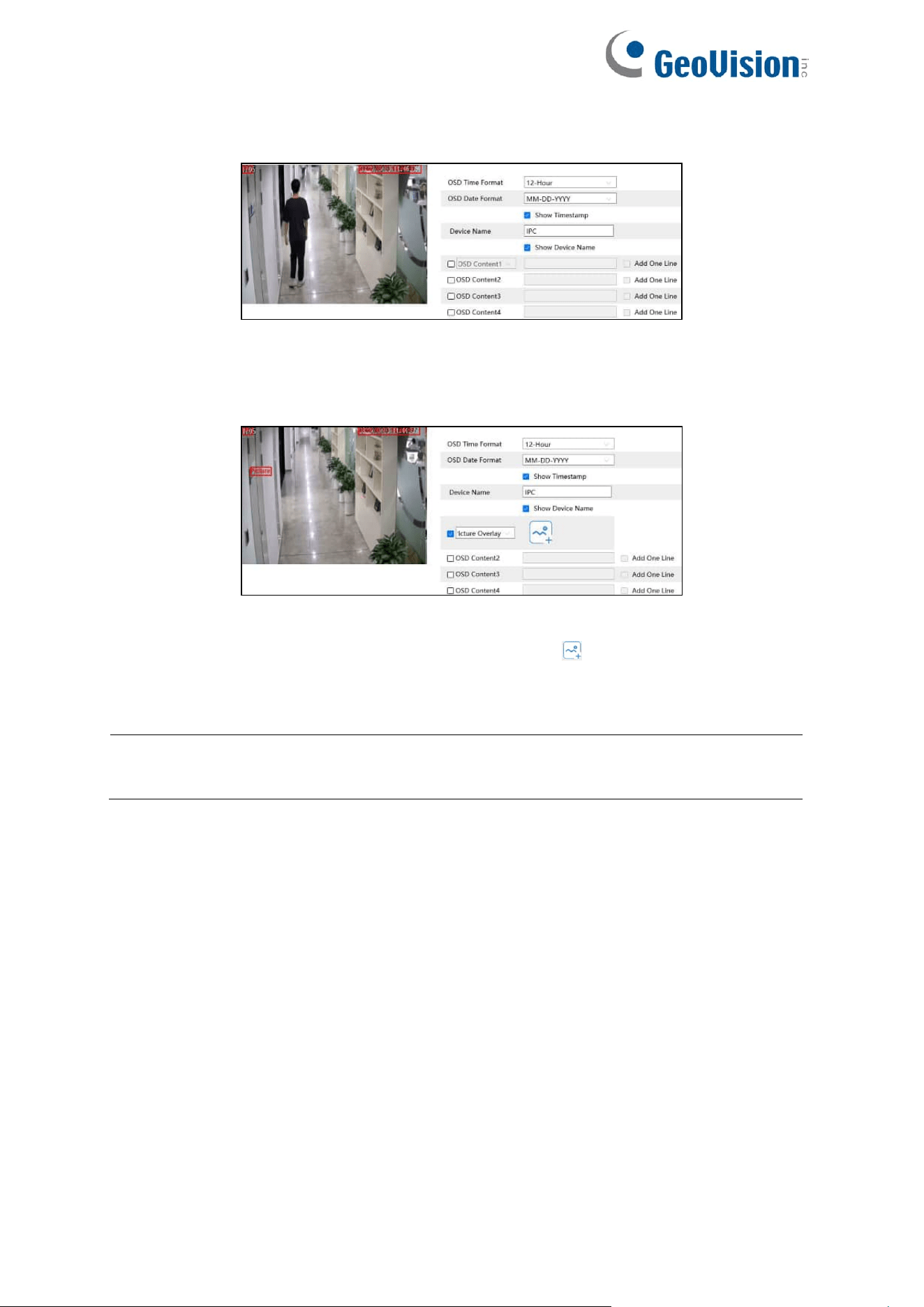
For GV-GBL4900 / GBL4911 / GDR4900 / GEB4900 / GFER6900 / GVD4910
Set time stamp, device name, OSD content and picture overlap here. After enabling the
corresponding display and entering the content, drag them to change their position. Then click
the “Save” button to save the settings.
Picture Overlap Settings:
Check “OSD Content1”, choose “Picture Overlay” and click to select the overlap picture.
Then click “Open” to upload the overlap picture. The pixel of the image shall not exceed
200*200, or it cannot be uploaded.
Note: For GV-GFER6900, the OSD information can only be overlaid on the Fisheye
channel.
32
4.2.4 Video Mask
Go to Image→Video Mask interface as shown below. A maximum of 4 zones can be set up.
To set up video mask:
1. Enable video mask.
2. Click the “Draw Area” button and then drag the mouse to draw the video mask area.
3. Click the “Save” button to save the settings.
4. Return to the live to verify that the area has been drawn as shown as blocked out in the
image.
To clear the video mask:
Click the “Clear” button to delete the current video mask area.
33
4.2.5 ROI Configuration
Go to Image→ROI Config interface as shown below. An area in the image can be set as a
region of interest. This area will have a higher bitrate than the rest of the image, resulting in
better image quality for the identified area.
1. Check “Enable” and then click the “Draw Area” button.
2. Drag the mouse to set the ROI area.
3. Set the level.
4. Click the “Save” button to save the settings.
34
4.2.6 Lens Control
This function is only available for the model with motorized zoom lens. Within this
section, zoom and focus can be controlled. If the image is out of focus after a manual
adjustment, one key focus can be used to set the focus automatically. Go to Config→Image→
Zoom/Focus interface to set.
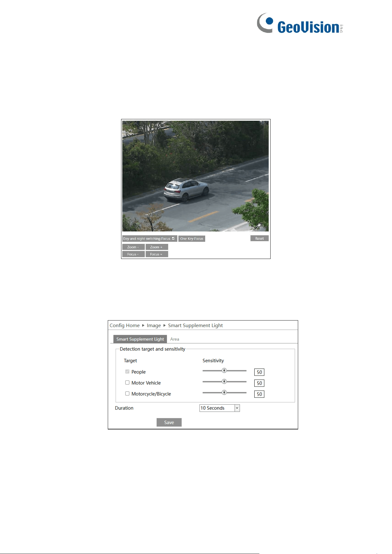
4.2.7 Smart Supplement Light
This function is only for GV-GEBF4911. You can set up vehicle motion sensitivity, duration,
and alarm area when the Smart Supplement Light function is enabled (Image→Display
Settings)
35
4.3 Alarm Configuration
4.3.1 Motion Detection
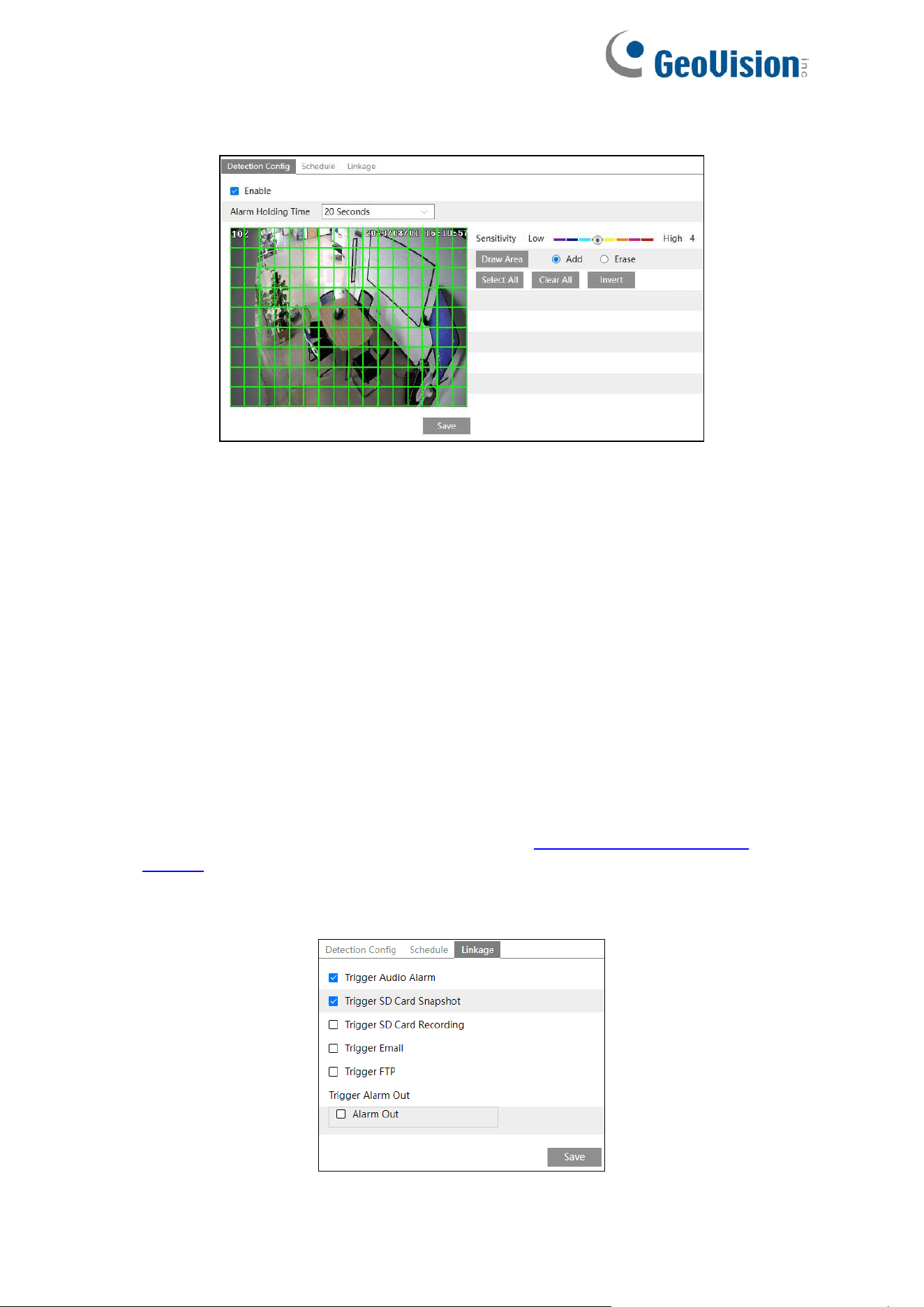
Go to Alarm→Motion Detection to set motion detection alarm.
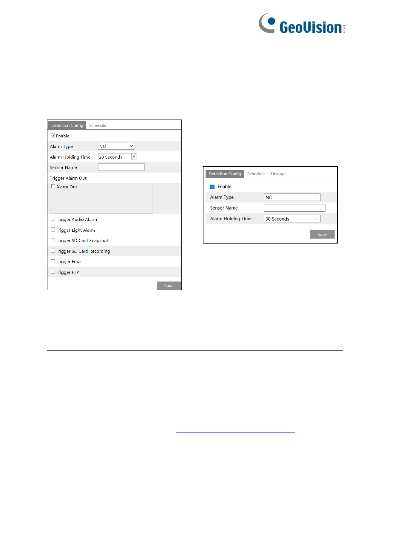
For GV-GEBF4911 / GFER6900
1. Check “Enable” check box to activate motion based alarms. If unchecked, the camera will
not send out any signals to trigger motion-based recording to the NVR or CMS, even if
there is motion in the video.
Alarm Holding Time: It refers to the interval time between the adjacent motion
detections. For instance, if the alarm holding time is set to 20 seconds, once the camera
detects a motion, it will go to alarm and would not detect any other motion in 20 seconds.
If there is another motion detected during this period, it will be considered as continuous
movement; otherwise, it will be considered as a single motion.
Alarm Out: If selected, this would trigger an external relay output that is connected to the
camera on detecting a motion based alarm.
Trigger Audio Alarm: If selected, the warning voice will be uttered on detecting a motion
based alarm. (Please set the warning voice first. See 4.3.6 Audio Alarm for details).
Trigger SD Snapshot: If selected, the system will capture images on motion detection
and save the images on an SD card.
Trigger SD Recording: If selected, video will be recorded on an SD card on motion
detection.
Trigger Email: If “Trigger Email” and “Attach Picture” are checked (email address must
be set first in the Email configuration interface), the captured pictures and triggered event
will be sent to the set addresses.
Trigger FTP: If “Trigger FTP” and “Attach Picture” are checked, the captured pictures will
be sent into FTP server address. Please refer to 4.6.10 FTP for more details.
36
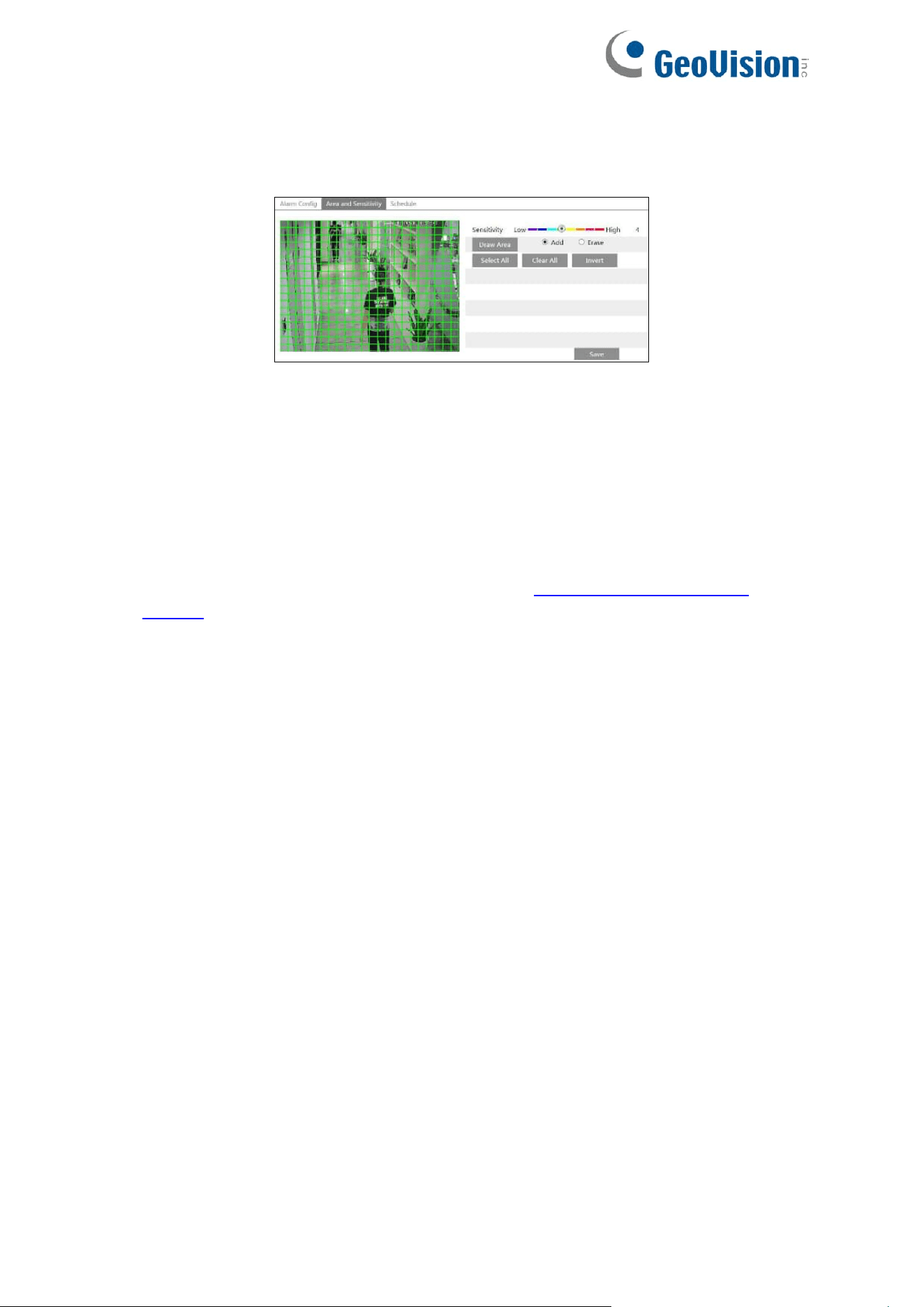
2. Set motion detection area and sensitivity. Click the “Area and Sensitivity” tab to go to the
interface as shown below.
Move the “Sensitivity” scroll bar to set the sensitivity. Higher sensitivity value means that
motion will be triggered more easily.
Select “Add” and click “Draw”. Drag the mouse to draw the motion detection area; Select
“Erase” and drag the mouse to clear motion detection area.
After that, click the “Save” to save the settings.
3. Set the schedule for motion detection. The schedule setup steps of the motion detection
are the same as the schedule recording setup (See 4.1.4.2 Schedule Recording
Settings).
37
4. For GV-GBL4900 / GBL4911 / GDR4900 / GEB4900 / GVD4910
1. Check “Enable” check box to activate motion-based alarms. If unchecked, the camera will
not send out any signals to trigger motion-based recording to the NVR or CMS, even if
there is motion in the video.
Alarm Holding Time: It refers to the interval time between the adjacent motion
detections. For instance, if the alarm holding time is set to 20 seconds, once the camera
detects a motion, it will go to alarm and would not detect any other motion in 20 seconds.
If there is another motion detected during this period, it will be considered as continuous
movement; otherwise, it will be considered as a single motion.
2. Set motion detection area and sensitivity.
Move the “Sensitivity” scroll bar to set the sensitivity. Higher sensitivity value means that
motion will be triggered more easily.
Select “Add” and click “Draw”. Drag the mouse to draw the motion detection area; Select
“Erase” and drag the mouse to clear motion detection area.
After that, click the “Save” to save the settings.
3. Set the schedule for motion detection. The schedule setup steps of the motion detection
are the same as the schedule recording setup (See 4.1.4.2 Schedule Recording
Settings).
4. Click “Linkage” to configure the alarm linkage items. For details, see For GV-GEBF4911
above.
38
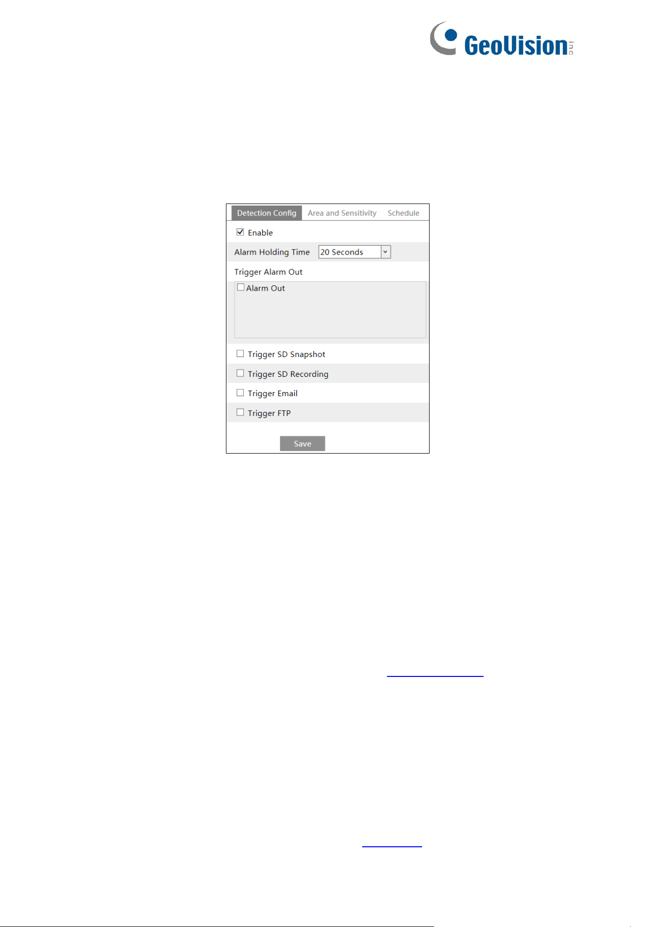
4.3.2 Exception Alarm
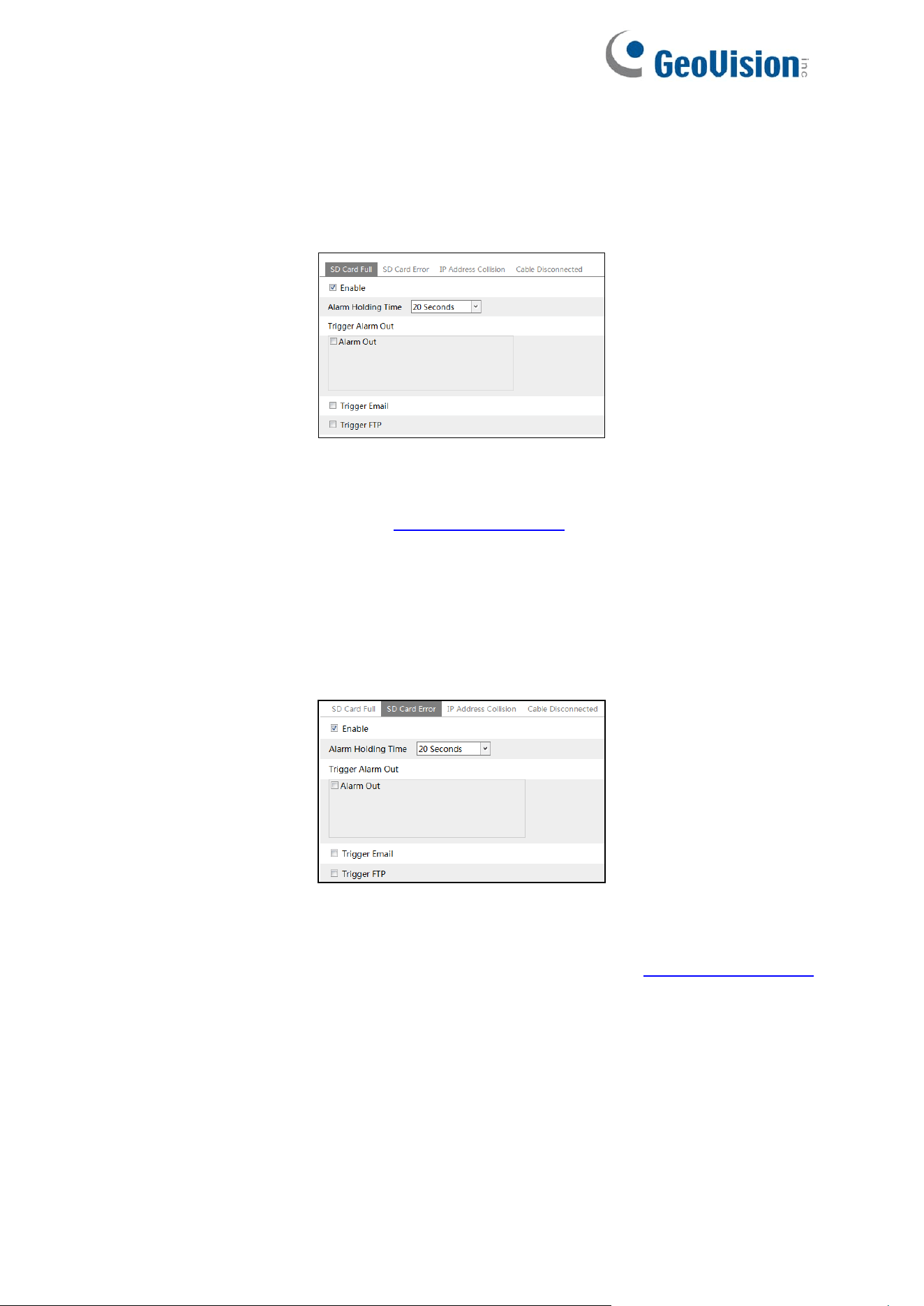
⚫ SD Card Full
1. Go to Config→Alarm→Exception Alarm→SD Card Full.
2. Click “Enable”.
3. Set the alarm holding time and alarm trigger options. The setup steps are the same as
motion detection. Please refer to 4.3.1 Motion Detection for details.
⚫ SD Card Error
When there are some errors in writing SD card, the corresponding alarms will be triggered.
1. Go to Config→Alarm→Exception Alarm→SD Card Error as shown below.
2. Click “Enable”.
3. Set the alarm holding time and alarm trigger options. Trigger alarm out, Email and FTP.
The setup steps are the same as motion detection. Please refer to 4.3.1 Motion Detection
for details.
39
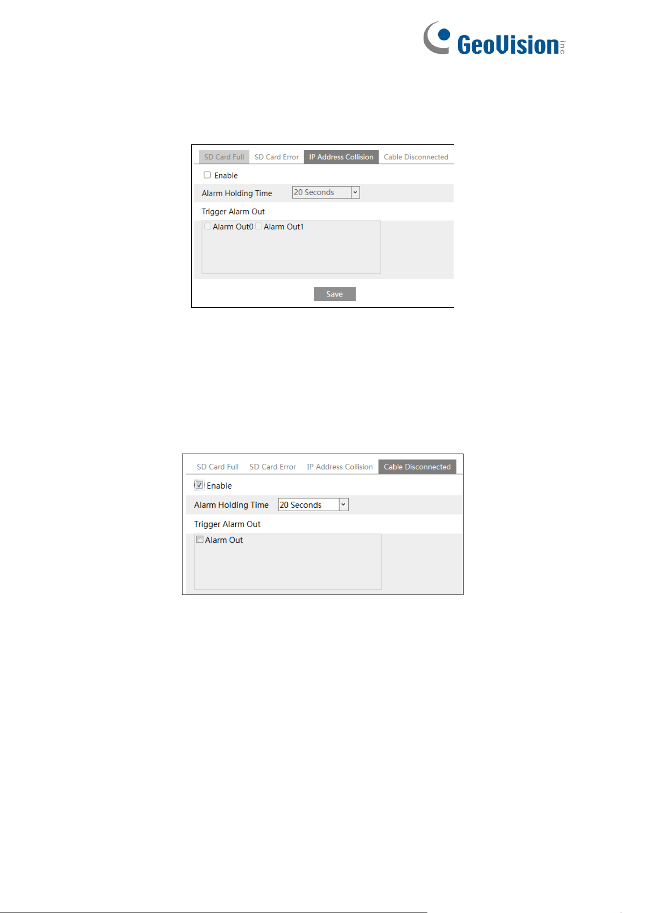
⚫ IP Address Conflict
1. Go to Config→Alarm→Exception Alarm→IP Address Collision as shown below.
2. Click “Enable” and set the alarm holding time.
3. Trigger alarm out. When the IP address of the camera conflicts with the IP address of
other devices, the system will trigger the alarm out.
⚫ Cable Disconnection
1. Go to Config→Alarm→Exception Alarm→Cable Disconnected as shown below.
2. Click “Enable” and set the alarm holding time.
3. Trigger alarm out. When the camera is disconnected, the system will trigger the alarm
out.
40
4.3.3 Alarm In
To set sensor alarm (alarm in):
Go to Config→Alarm→Alarm In interface as shown below.
GV-GEBF4911 / GFER6900
GV-GBL4900 / GBL4911 / GDR4900 /
GEB4900 / GVD4910
1. Click “Enable” and set the alarm type, alarm holding time and sensor name.
2. Set alarm trigger options. The setup steps are the same as motion detection. Please refer
to 4.3.1 Motion Detection for details.
Note: For alarm trigger options: if Day/night switch linkage is enabled, the system will
switch to day or night mode upon the occurrence of the sensor alarm. Note that this is only
applicable to GV-GBL4900 / GBL4911 / GDR4900 / GEB4900 / GFER6900 / GVD4910.
3. Click “Save” button to save the settings.
4. Set the schedule of the sensor alarm. The setup steps of the schedule are the same as
the schedule recording setup. (See 4.1.4.2 Schedule Recording Settings).
If there are two sensors, please select the sensor ID. Click “Apply settings to” to quickly apply
the settings to the other alarm input.
41
4.3.4 Alarm Out
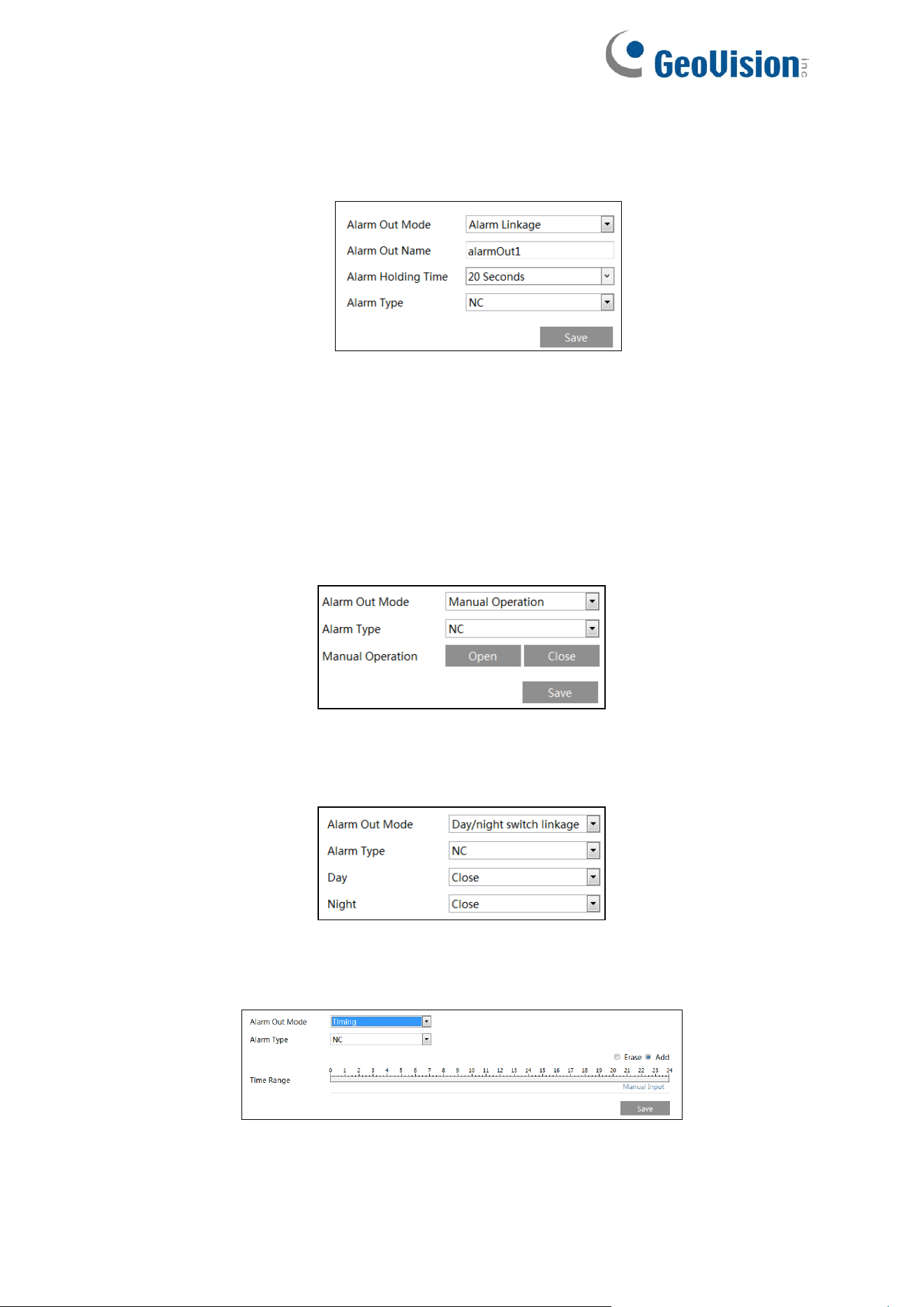
Go to Config→Alarm→Alarm Out.
Alarm Out ID: The alarm out can be set respectively by selecting alarm out ID.
Alarm Out Mode: Alarm linkage, manual operation, day/night switch linkage and timing are
optional.
Alarm Linkage: Having selected this mode, select alarm out name, alarm holding time at the
“Alarm Holding Time” pull down list box and alarm type.
Manual Operation: Having selected this mode, select the alarm type and click “Open” to
trigger the alarm out immediately; click “Close” to stop alarm.
Day/Night Switch Linkage (for GV-GBL4900 / GBL4911 / GDR4900 / GEB4900 /
GFER6900 / GVD4910): Having selected this mode, select the alarm type and choose to
open or close alarm out when the camera switches to day or night mode.
Timing: Select the alarm type. Then click “Add” and drag the mouse on the timeline to set the
schedule of alarm out; click “Erase” and drag the mouse on the timeline to erase the set time
schedule. After this schedule is saved, the alarm out will be triggered in the specified time.
42
4.3.5 Alarm Server
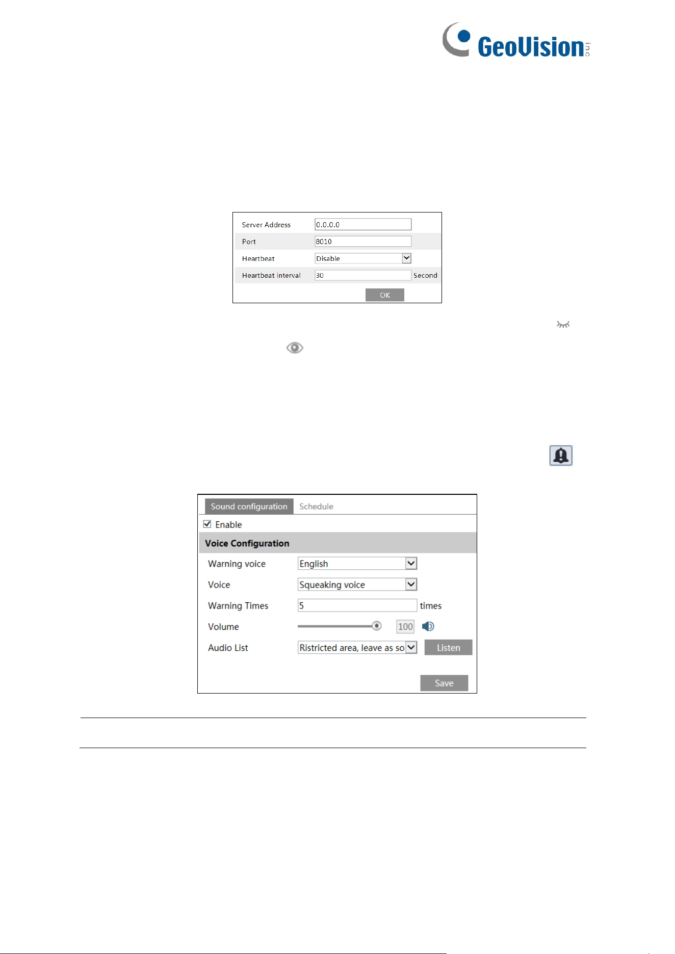
Go to Alarm→Alarm Server interface as shown below.
Set the server address, port, heartbeat and heartbeat interval. When an alarm occurs, the
camera will transfer the alarm event to the alarm server. If an alarm server is not needed,
there is no need to configure this section.
For GV-GBL4900 / GBL4911 / GDR4900 / GEB4900 / GFER6900 / GVD4910: Click to
view the entire server address; click to hide a part of sensitive data.
4.3.6 Audio Alarm
Go to Alarm→Audio Alarm interface as shown below.
Enable audio alarm. If disabled, the warning sound will not be uttered by clicking the
icon in the live view interface.
Note: The Audio Alarm function is not applicable to GV-GFER6900.
43
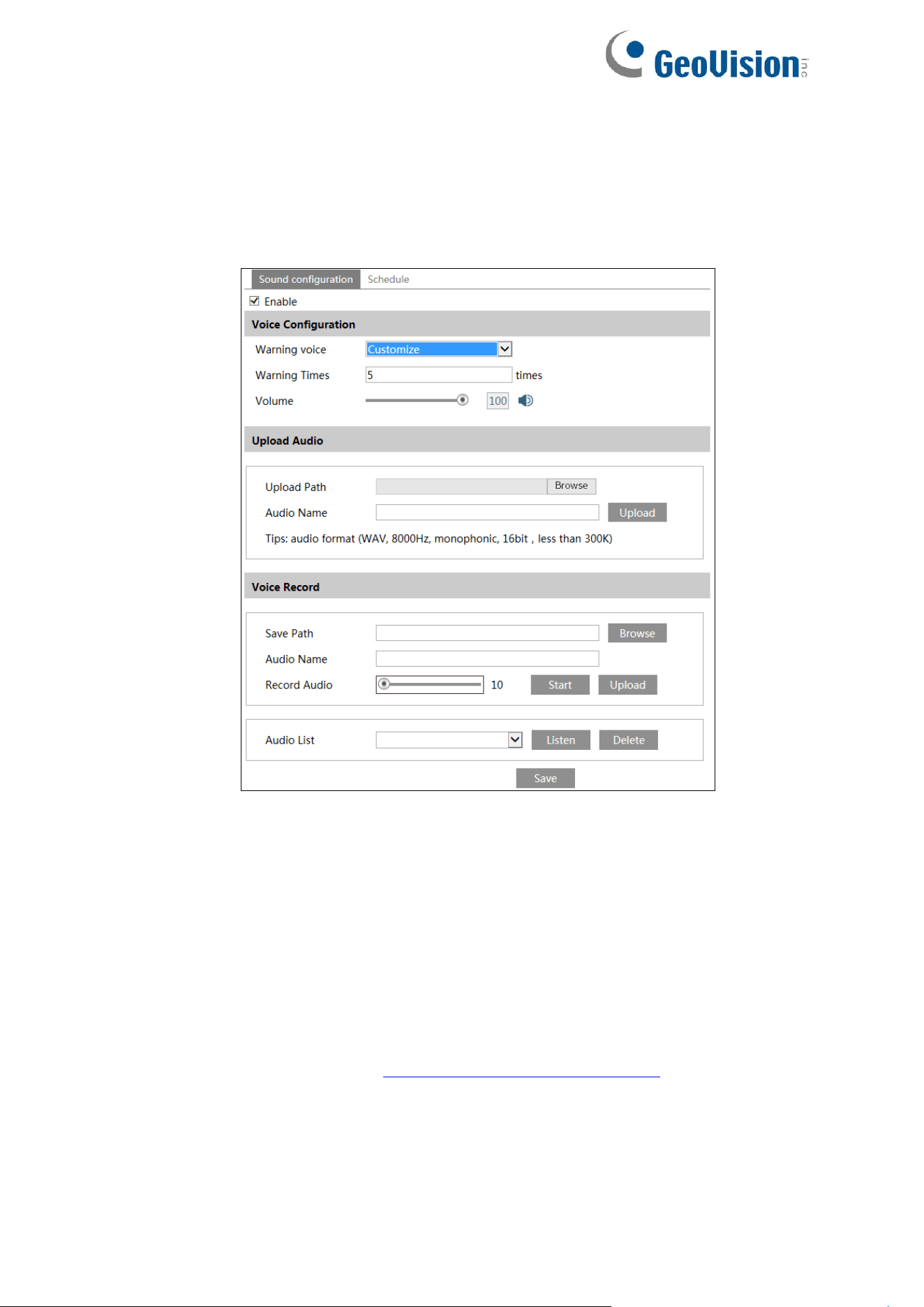
1. Select the warning voice. If you want to customize the voice, you can chose “Customize”.
Click “Browse” to choose the audio file you to upload and then enter the audio name.
Finally, click “Upload” to upload the audio file. Note that the format of the audio file must
meet the requirement, or it will not be uploaded. After you upload the audio file, you can
select the audio name from the audio list and click “Listen” to listen to it. Click “Delete” to
delete the audio.
You can also record your own voice in the above interface and then upload.
⚫ Insert the microphone into your PC.
⚫ Click “Browse” to choose the save path of the audio you want to record.
⚫ Set the record audio volume and then click “Start” to start recording your voice.
⚫ Click “Upload” to upload your customized voice.
2. Select the voice and then set the warning times and volume as needed. Warning times: it
ranges from 1 to 50.
3. Set the schedule of audio alarm. The setup steps of the schedule are the same as the
schedule recording setup. (See 4.1.4.2 Schedule Recording Settings).
4. Click OK to save the settings.
44
4.3.7 Light Alarm
Go to Alarm→Audio Alarm interface as shown below.
Note: The Audio Alarm function is only applicable to GV-GEBF4911.
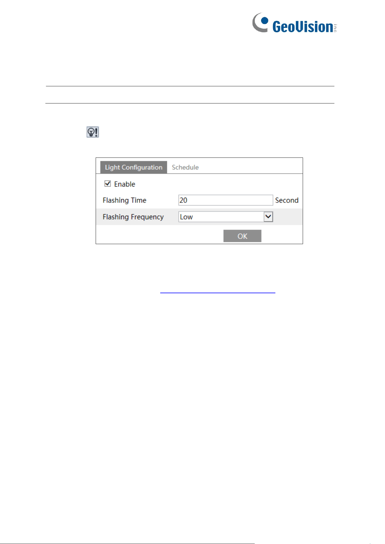
1. Enable light alarm as needed. If it is disabled, the flashing light will not be turned on by
clicking in the live view interface.
2. Set the flashing time and frequency of the light.
Flashing Time: The flashing time ranges from 1 second to 60 seconds.
Flashing Frequency: Three options – low, middle and high
3. Set the schedule of audio alarm. The setup steps of the schedule are the same as the
schedule recording setup. (See 4.1.4.2 Schedule Recording Settings).
4.3.8 Video Exception
For more details, see 4.4.2 Video Exception.
45
4.3.9 Audio Exception
Alarms will be triggered when the abnormal sound is detected in the surveillance scene, such
as the sudden increase/decrease of the sound intensity.
Note: The Audio Exception function is only applicable to GV-GBL4900 / GBL4911 /
GDR4900 / GEB4900 / GVD4910.
To set audio exception detection:
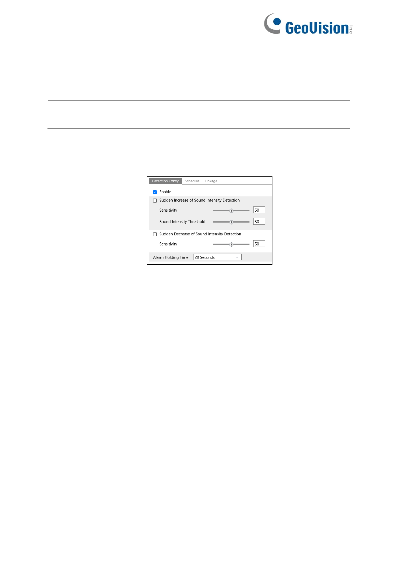
1. Go to Alarm→Audio Exception interface as shown below.
2. Enable audio exception.
3. Select the audio exception detection types.
Sudden Increase of Sound Intensity Detection: Detect sudden increase of sound
intensity. If enabled, sensitivity and sound intensity threshold are configurable. Alarms will
be triggered when the detected sound intensity exceeds the sound threshold.
Sensitivity: The higher the value is, the easier the alarm will be triggered.
Sound Intensity Threshold: It is the sound intensity reference for the detection. The
lower the value is, the easier the alarm will be triggered. It is recommended to set as the
average sound intensity in the environment. The louder the environment sound, the
higher the value should be. Please adjust it according to the actual environment
condition.
Sudden Decrease of Sound Intensity Detection: Detect sudden decrease of sound
intensity. Please set the sensitivity as needed. The higher the value is, the easier the
alarm will be triggered.
46
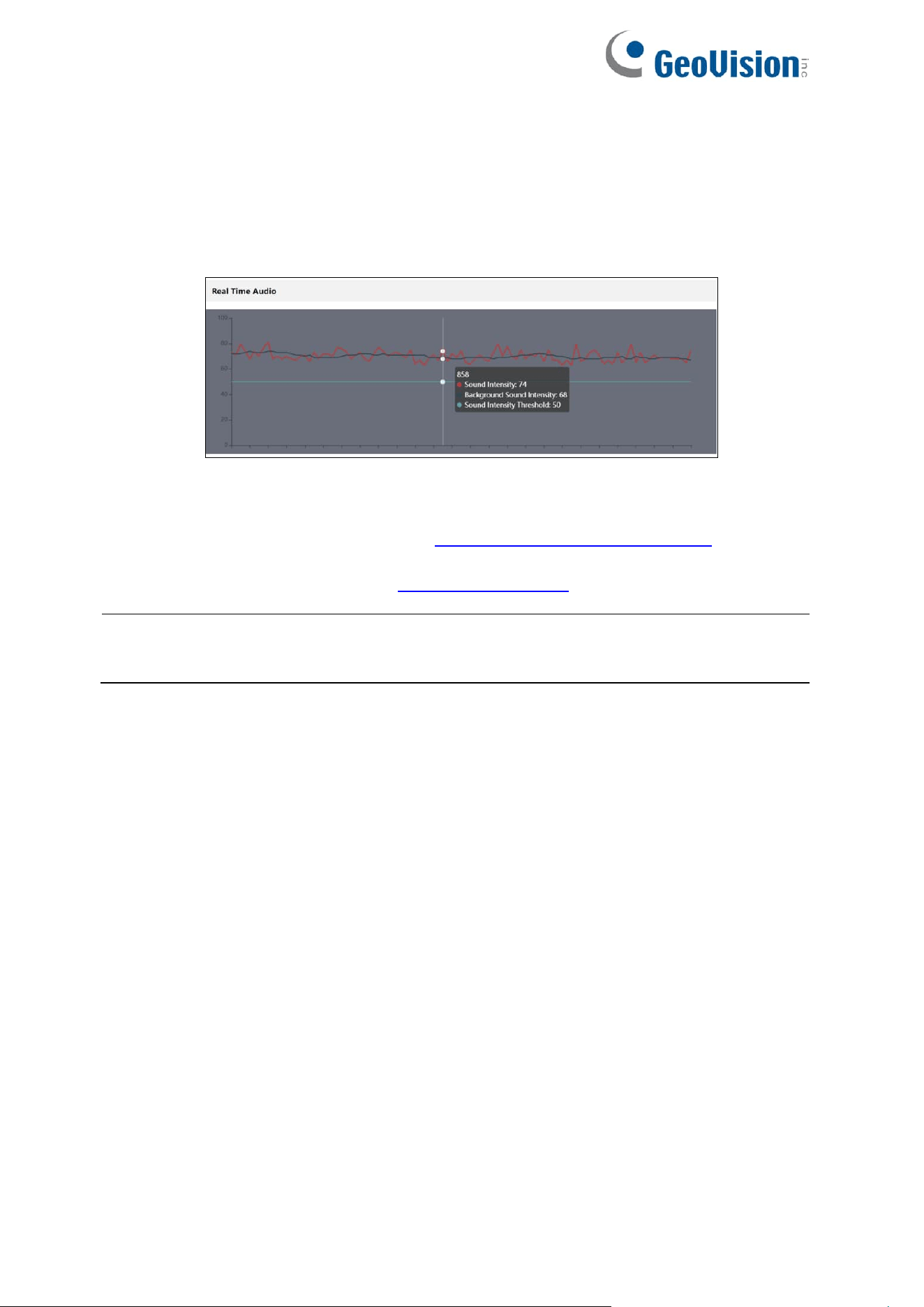
Real-time audio graphic:
Red wavy line stands for the current detected sound intensity.
Navy blue line stands for the environment (background) sound intensity.
Green line stands for the sound intensity threshold.
In order to reduce false alarm, it is recommended to set the sensitivity and sound intensity
threshold according to the real-time audio graphic.
4. Set the alarm holding time and click “Save” to save the settings.
5. Set the schedule of the audio exception detection. The setup steps of schedule are the
same as the schedule recording (See 4.1.4.2 Schedule Recording Settings).
6. Click “Linkage” to configure the alarm linkage items. The setup steps are the same as
motion detection. Please refer to 4.3.1 Motion Detection for details.
Note: The alarm recording type triggered by audio exception event is “Common”. In the
search interface, you can search the recorded files of audio exception by selecting the
“Common” event.

47
4.4 Event Configuration
For more accuracy, here are some recommendations for installation.
⚫ Cameras should be installed on stable surfaces, as vibrations can affect the accuracy of
detection.
⚫ Avoid pointing the camera at the reflective surfaces (like shiny floors, mirrors, glass, lake
surfaces and so on).
⚫ Avoid places that are narrow or have too much shadowing.
⚫ Avoid scenario where the object’s color is similar to the background color.
⚫ At any time of day or night, please make sure the image of the camera is clear and with
adequate and even light, avoiding overexposure or too much darkness on both sides.
The event types supported by GV-Cloud Cameras are as follows.
1. Video Analytics Events:
Object Abandoned / Missing Detection, Video Exception (Scene Change Detection,
Video Blur Detection, Abnormal Color Detection)
2. AI Analytics Events:
a. Smart Events: Line Crossing, Region Entrance, Region Exiting, Target Counting by
Line, Target Counting by Area, Region Intrusion, Crowd Density, Heat Map, Video
Metadata, Loitering Detection, Illegal Parking Detection
b. Face Events: Face Detection
The configurations and supported AI analytics for each model, along with stream mode
compatibility, are detailed as follows.
For GV-GBL4900 / GBL4911 / GDR4900 / GEB4900 / GEBF4911 / GVD4910:
1. Multiple AI events can be enabled simultaneously. However, enabling more than two
smart events may compromise speed and detection accuracy. Limit the number of smart
events to two for optimal camera performance and complete detection.
2. Smart events and face events cannot be enabled at the same time.
3. Only 2 smart events are supported when connected to GV-Cloud VMS or GV-Center V2.
48
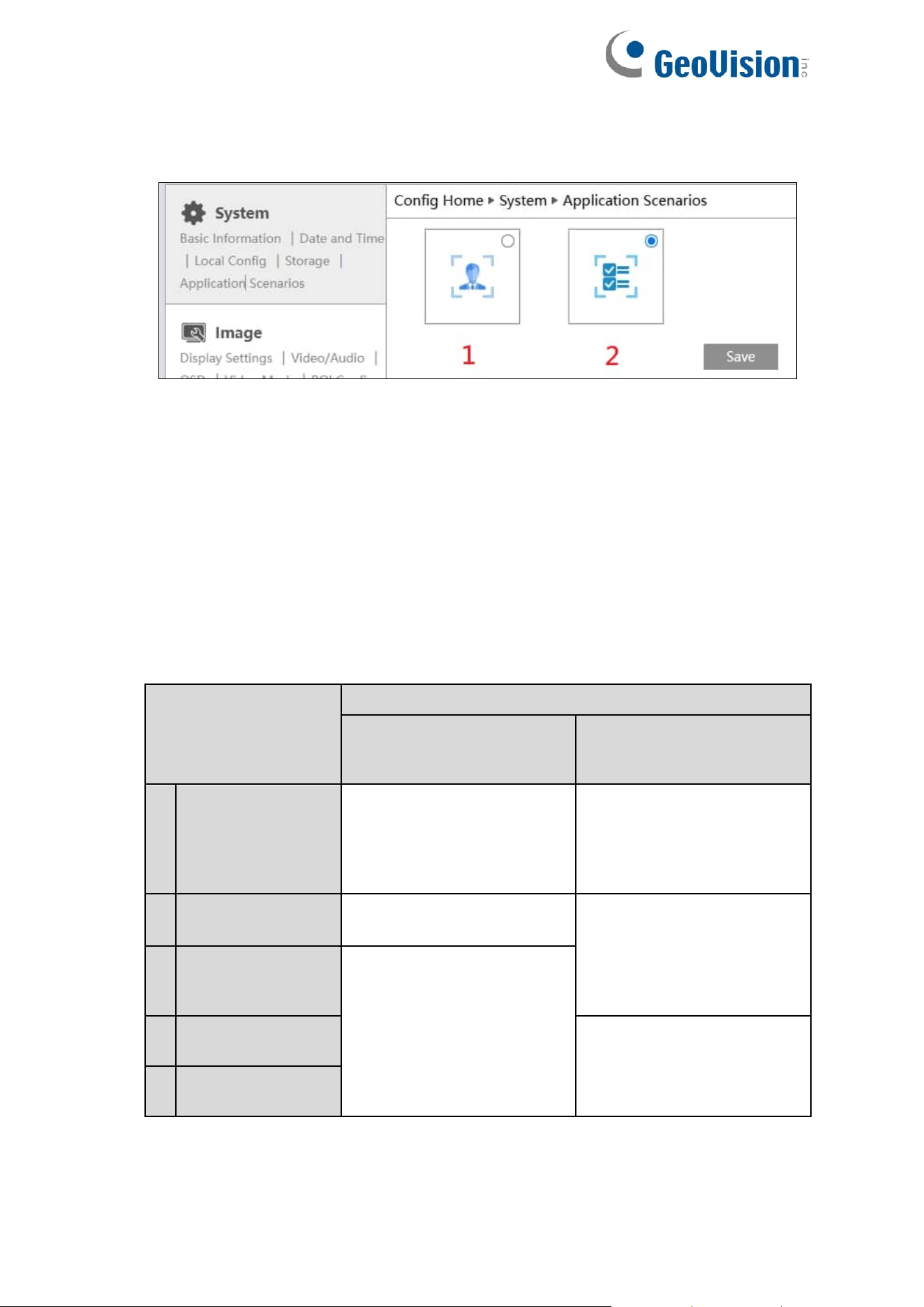
5. You can enable the AI event type as needed. Go to System→Application Scenarios
→Enable Event interface as shown below.
AI Event Types: 1. Face Event; 2. Smart Event
The default AI event type is smart event. To switch to face event, select it and click Save.
After a successful reboot, the corresponding event will be displayed. Configure as
needed.
For GV-GFER6900:
1. Only 1 AI event can be enabled at a time: smart events only, as GV-GFER6900 does not
support face events.
2. Only 1 smart event is supported when connected to GV-Cloud VMS or GV-Center V2.
3. Supported AI analytics and stream modes:
Stream Mode
Supports AI Analytics
Ceiling Mount
(Human detection only)
Wall or Desktop Mount
(Human and vehicle
detection)
1
Fisheye View
Target Counting by Line, Line
Crossing, Region Entrance,
Region Exiting, Region
Intrusion, Crowd Density,
Heat Map
N/A
2
Panoramic View
N/A
Target Counting by Line, Line
Crossing, Region Entrance,
Region Exiting, Region
Intrusion, Crowd Density
3
Fisheye
+ Panoramic View
+ 3 PTZ
Target Counting by Line, Line
Crossing, Region Entrance,
Region Exiting, Region
Intrusion, Crowd Density,
Heat Map
4
Fisheye
+ 4 PTZ Fisheye
N/A
5
Fisheye
+ 4 PTZ Fusion
49
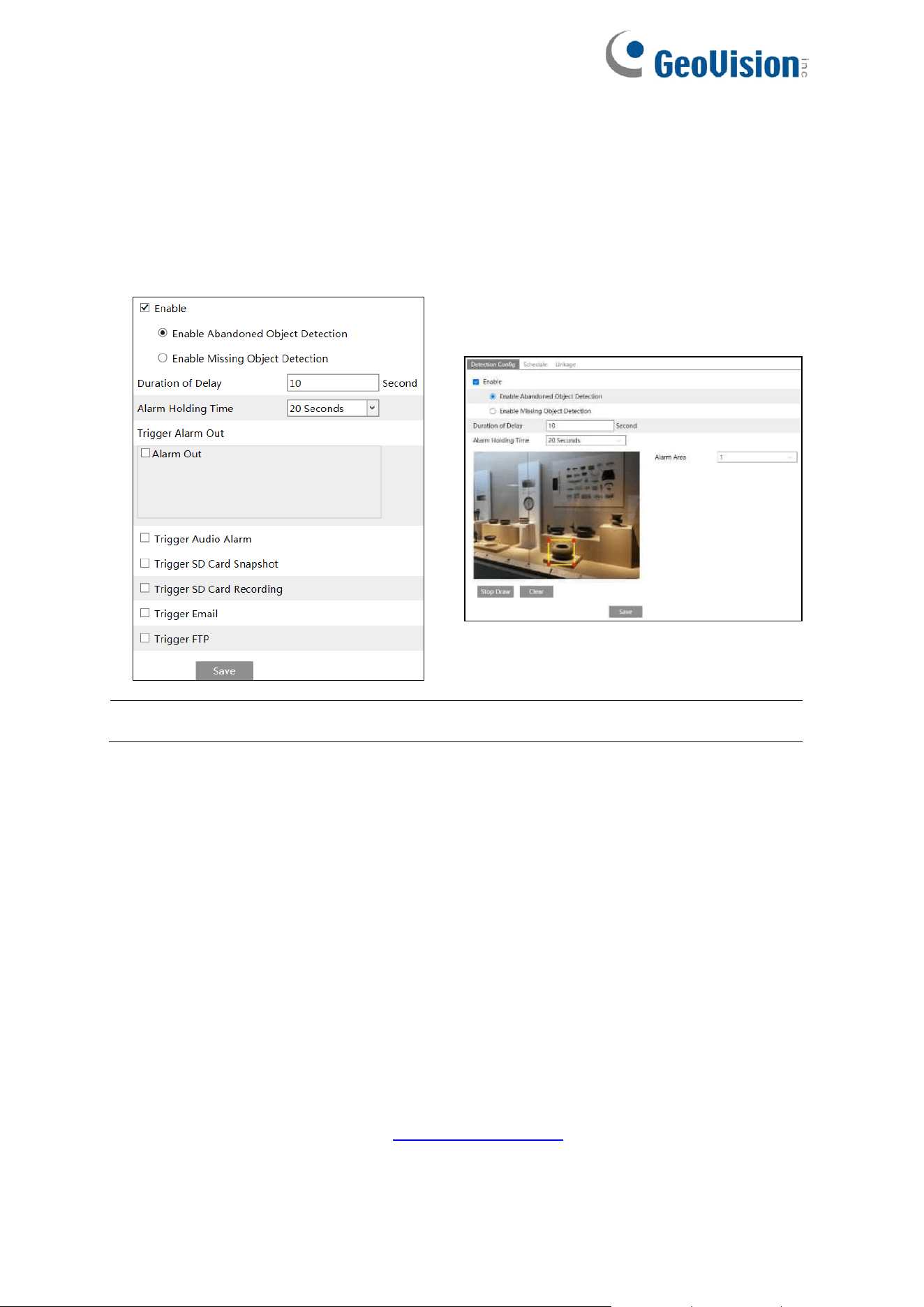
4.4.1 Object Abandoned / Missing
Alarms will be triggered when the objects are removed from or left at the pre-defined area.
To set abandoned/missing object detection:
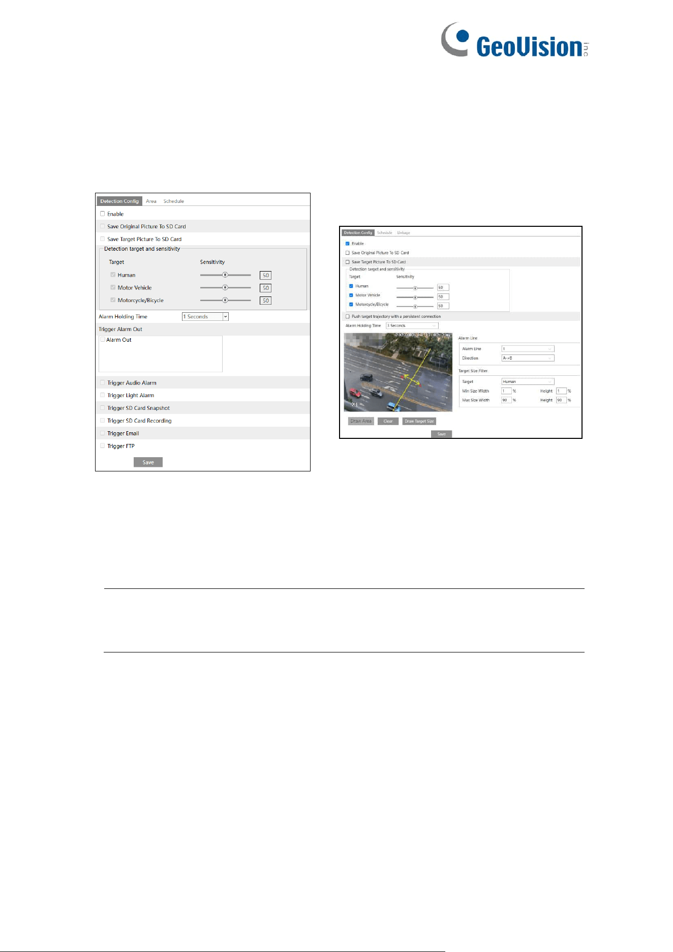
Go to Config→Event→Object Abandoned/Missing interface as shown below.
GV-GEBF4911
GV-GBL4900 / GBL4911 / GDR4900 /
GEB4900 / GVD4910
Note: The Object Abandoned / Missing function is not applicable to GV-GFER6900.
1. Enable abandoned/missing object detection and then select the detection type.
Enable Abandoned Object Detection: Alarms will be triggered if there are items left in
the pre-defined area.
Enable Missing Object Detection: Alarms will be triggered if there are items missing in
the pre-defined area.
Duration of Delay: It is the alarm delay time of the object left in the region (ranging from
10~3600s) or the alarm delay time of the object removed from the region (ranging from
3~3600s). For example, if “Enable Abandoned Object Detection” is selected and the
duration of delay is set as 10, alarms will be triggered after the object is left and stay in the
region for 10s, but when someone takes away the object within 10s, alarms will not be
triggered.
Set the alarm holding time and alarm trigger options. The setup steps are the same as
motion detection. Please refer to 4.3.1 Motion Detection for details.
50
For GV-GEBF4911
2. Click “Save” button to save the settings.
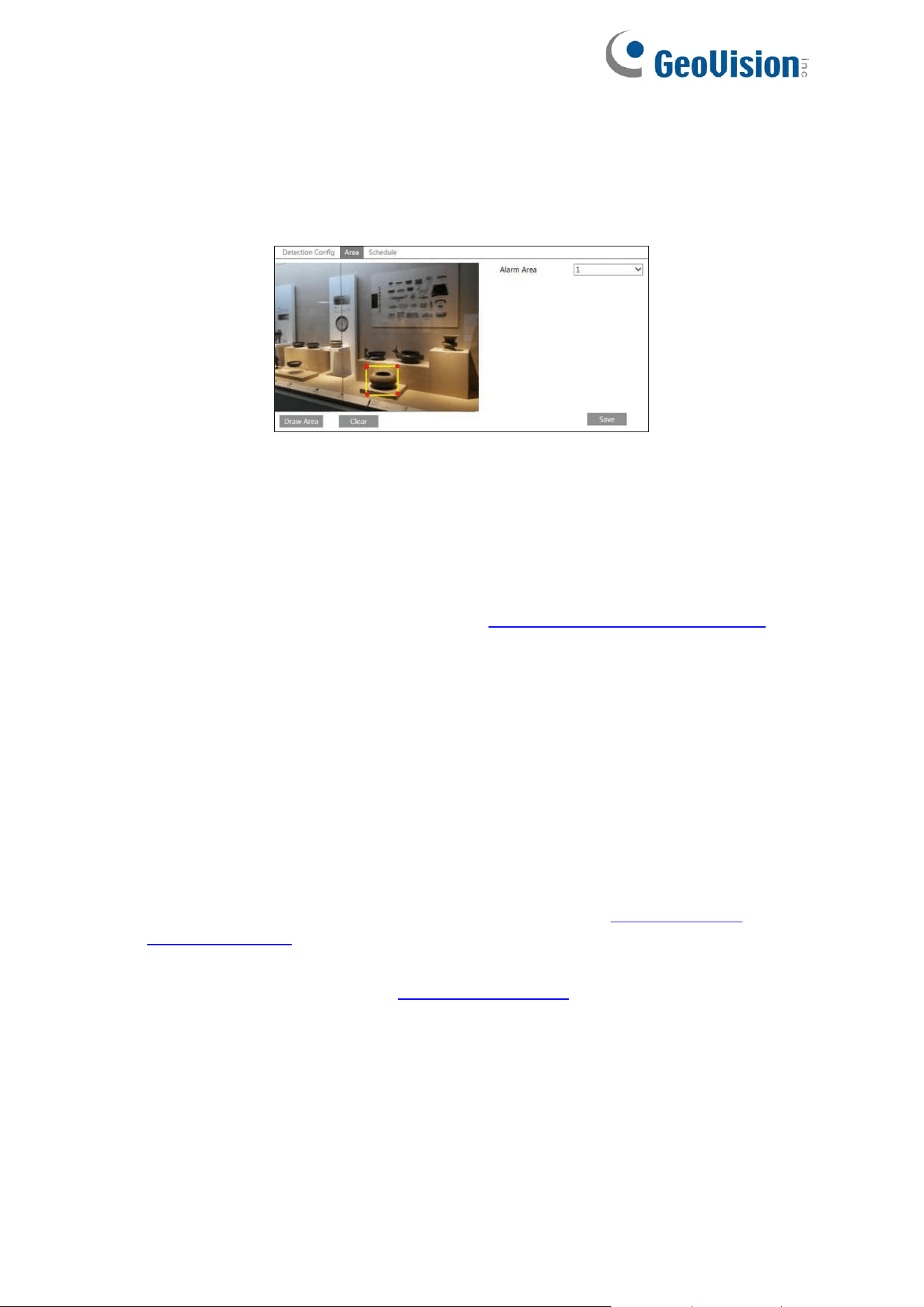
3. Set the alarm area of the abandoned/missing object detection. Click the “Area” tab to go
to the interface as shown below.
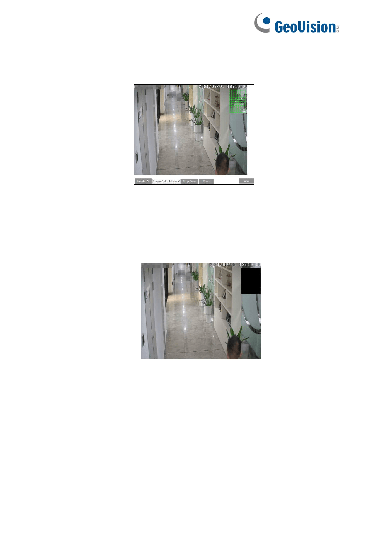
Set the alarm area number and then enter the desired alarm area name. Only one alarm
area can be added. Click the “Draw Area” button and then click around the area where
you want to set as the alarm area in the image (the alarm area should be a closed area).
Click the “Stop Draw” button to stop drawing. Click the “Clear” button to delete the alarm
area. Click the “Save” button to save the settings.
4. Set the schedule of the abandoned/missing object detection. The setup steps of schedule
are the same as the schedule recording (See 4.1.4.2 Schedule Recording Settings).
For GV-GBL4900 / GBL4911 / GDR4900 / GEB4900 / GVD4910
3. Set the alarm area of the abandoned/missing object detection. Set the alarm area
number and then enter the desired alarm area name. Only one alarm area can be added.
Click the “Draw Area” button and then click around the area where you want to set as the
alarm area in the image (the alarm area should be a closed area). Click the “Stop Draw”
button to stop drawing. Click the “Clear” button to delete the alarm area. Click the “Save”
button to save the settings.
4. Click “Save” button to save the settings.
5. Set the schedule of the abandoned/missing object detection. The setup steps of schedule
are the same as the motion detection schedule settings (See 4.1.4.2 Schedule
Recording Settings).
6. Click “Linkage” to configure the alarm linkage items. The setup steps are the same as
motion detection. Please refer to 4.3.1 Motion Detection for details.

51
※ The configuration requirements of camera and surrounding areas
1. The range of the detection object should occupy from 1/50 to 1/3 of the entire image.
2. The detection time of objects in the camera shall be from 3 to 5 seconds.
3. The defined area cannot be covered frequently and continuously (like people and traffic
flow).
4. It is necessary for abandoned/missing object detection that the drawn frame must be very
close to the margin of the object in enhancing the sensitivity and accuracy of the
detection.
5. Abandoned/missing object detection cannot determine the objects’ ownership. For
instance, there is an unattended package in the station. Abandoned object detection can
detect the package itself but it cannot determine to whom it belongs to.
6. Try not to enable abandoned/missing object detection when light changes greatly in the
scene.
7. Try not to enable abandoned/missing object if there are complex and dynamic
environments in the scene.
8. Adequate light and clear scenery are very important to abandoned/missing object
detection.
52
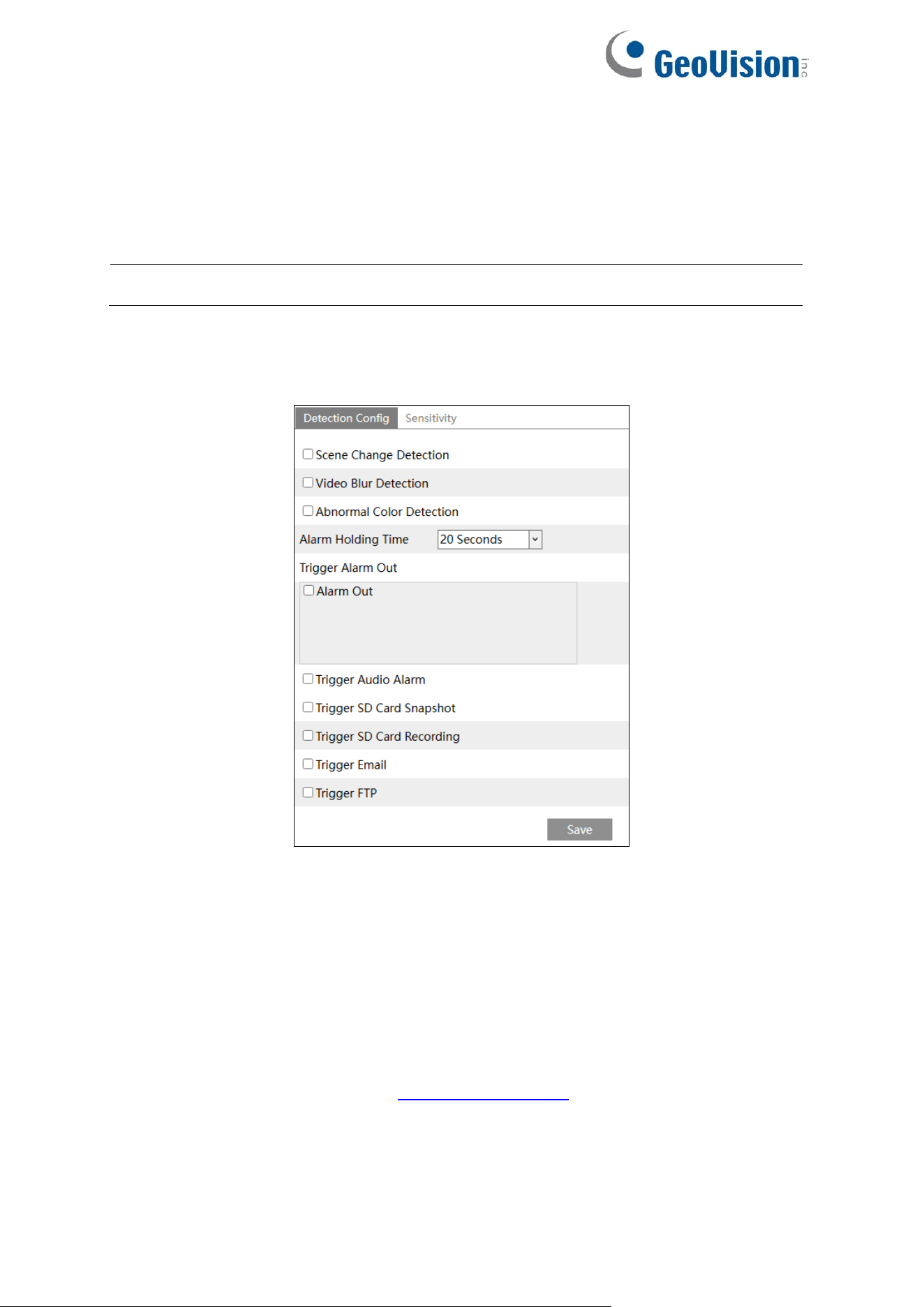
4.4.2 Video Exception
This function can detect changes in the surveillance environment affected by the external
factors.
To set exception detection:
Note: The Video Exception function is not applicable to GV-GFER6900.
For GV-GEBF4911
Go to Config→Event→Video Exception interface as shown below.
1. Enable the applicable detection that’s desired.
Scene Change Detection: Alarms will be triggered if the scene of the monitor video has
changed.
Video Blur Detection: Alarms will be triggered if the video becomes blurry.
Abnormal Color Detection: Alarms will be triggered if the image is abnormal caused by
color deviation.
2. Set the alarm holding time and alarm trigger options. The setup steps are the same as
motion detection. Please refer to 4.3.1 Motion Detection for details.
3. Click “Save” button to save the settings.
53
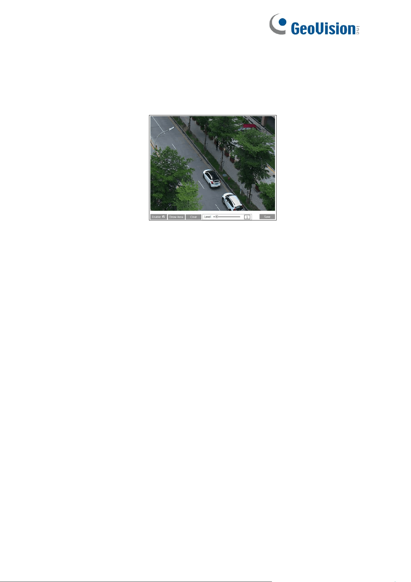
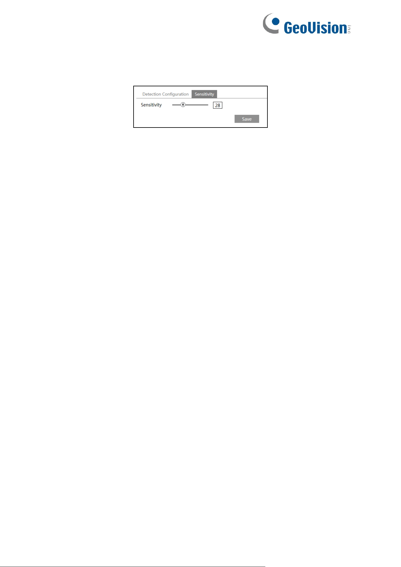
4. Set the sensitivity of the exception detection. Click “Sensitivity” tab to go to the interface
as shown below.
Drag the slider to set the sensitivity value or directly enter the sensitivity value in the
textbox. Click “Save” button to save the settings.
The sensitivity value of Scene Change Detection: The higher the value is, the more
sensitive the system responds to the amplitude of the scene change.
The sensitivity value of Video Blur Detection: The higher the value is, the more
sensitive the system responds to the blurriness of the image.
The sensitivity value of Abnormal Color Detection: The higher the value is, the more
sensitive the system responds to the color shift of the image.
54
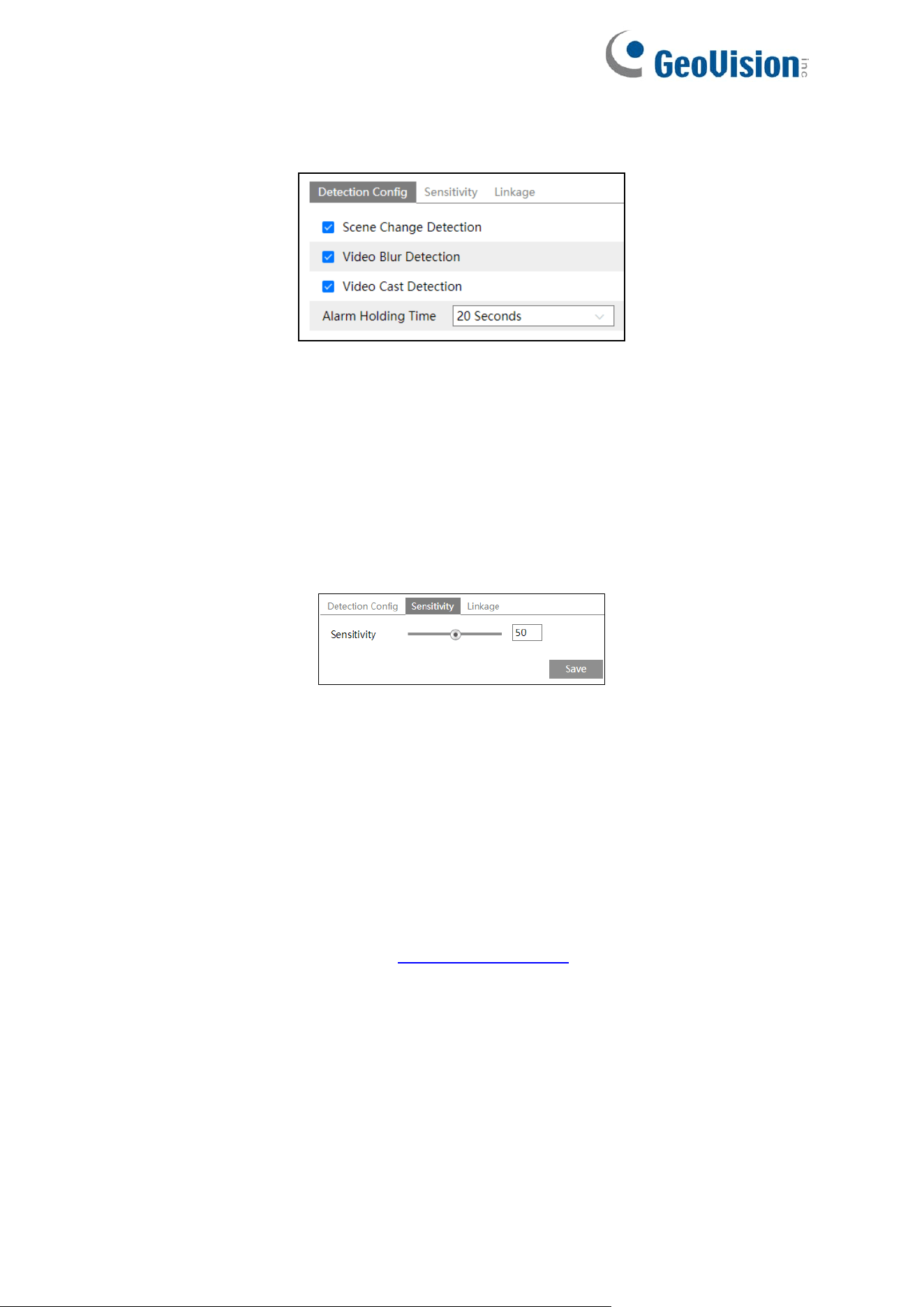
For GV-GBL4900 / GBL4911 / GDR4900 / GEB4900 / GVD4910
Go to Config→Alarm→Video Exception interface as shown below.
1. Enable the applicable detection that’s desired.
Scene Change Detection: Alarms will be triggered if the scene of the monitor video has
changed.
Video Blur Detection: Alarms will be triggered if the video becomes blurry.
Video Cast Detection: Alarms will be triggered if the image is abnormal because of color
deviation.
2. Set the alarm holding time.
3. Click “Save” button to save the settings.
4. Set the sensitivity of the exception detection. Click “Sensitivity” tab to go to the interface
as shown below.
Drag the slider to set the sensitivity value or directly enter the sensitivity value in the
textbox. Click “Save” button to save the settings.
The sensitivity value of Scene Change Detection: The higher the value is, the more
sensitive the system responds to the amplitude of the scene change.
The sensitivity value of Video Blur Detection: The higher the value is, the more
sensitive the system responds to the blurriness of the image.
The sensitivity value of Video Cast Detection: The higher the value is, the more
sensitive the system responds to the color shift of the image.
5. Click “Linkage” to configure the alarm linkage items. The setup steps are the same as
motion detection. Please refer to 4.3.1 Motion Detection for details.
After checking “Trigger SD Card Snapshot” and/or “Trigger SD Card Recording”, you can
search the recorded files or snapshots of video exception by selecting the “Common” event.
※ The requirements of camera and surrounding area
1. Auto-focusing function should not be enabled for exception detection.
2. Try not to enable exception detection when light changes greatly in the scene.
3. Please contact us for more detailed application scenarios.
55
4.4.3 Line Crossing
Line Crossing: Alarms will be triggered if the target crosses the pre-defined alarm lines.
Go to Config→Event→Line Crossing interface as shown below.
GV-GEBF4911 / GFER6900
GV-GBL4900 / GBL4911 / GDR4900 /
GEB4900 / GVD4910
1. Enable line crossing alarm and select the snapshot type and the detection target.
Save Original Picture to SD Card: If it is enabled, the detected original pictures will be
captured and saved to the SD card when the targets cross the alarm line.
Save Target Picture to SD Card: If it is enabled, the detected target cutout pictures will
be captured and saved to the SD card when the targets cross the alarm line.
Note: To save snapshots to the local PC, please enable “Local Smart Snapshot
Storage” in the local config interface first. To save snapshots to the SD card, please
install an SD card first.
Detection Target:
⚫ Human: Select it and then alarms will be triggered if someone crosses the
pre-defined alarm lines.
⚫ Motor Vehicle: Select it and then alarms will be triggered if a vehicle with four or
more wheels (eg. a car, bus or truck) crosses the pre-defined alarm lines.
⚫ Motorcycle/Bicycle: Select it and then alarms will be triggered if a vehicle with two
wheels (eg. a motorcycle or bicycle) crosses the pre-defined alarm lines.
All of the three types of objects can be selected simultaneously. Please select the
detection objects as needed. If no object / target is selected, alarms will not be triggered
even if line crossing detection is enabled.
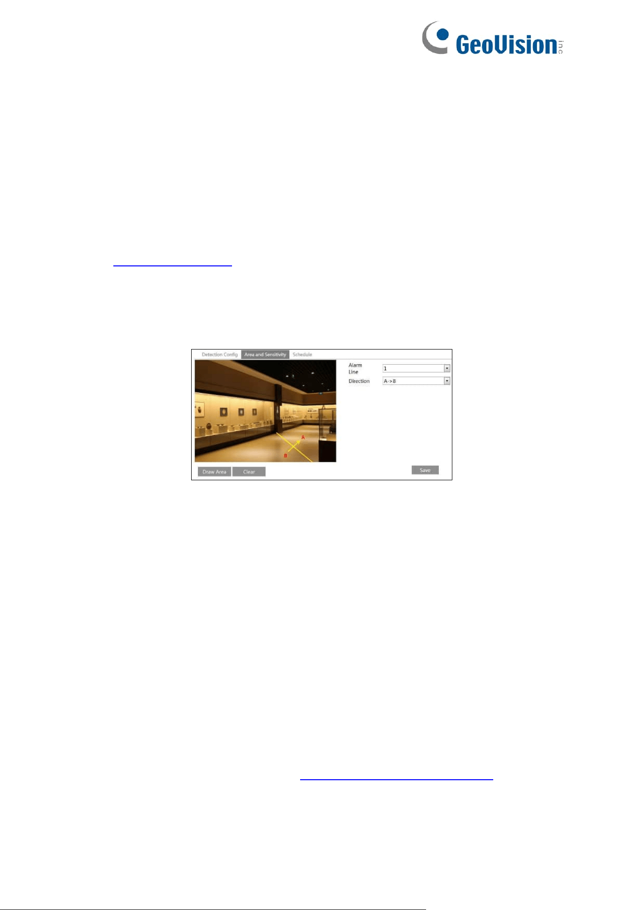
56
Push target trajectory with a persistent connection (for GV-GBL4900 / GBL4911 /
GDR4900 / GEB4900 / GFER6900 / GVD4910): Push target trajectory (moving
coordinate) to API test tool with a persistent connection. If enabled, the system will push
the target trajectory upon detecting a target. If disabled, the system will push the target
trajectory only when triggering line crossing alarm.
2. Set the alarm holding time.
For GV-GEBF4911 / GFER6900
3. Set alarm trigger options. The setup steps are the same as motion detection. Please refer
to 4.3.1 Motion Detection for details.
4. Click “Save” button to save the settings.
5. Set area and sensitivity of the line crossing alarm. Click the “Area and Sensitivity” tab
(“Area” tab for GV-GFER6900) to go to the interface as shown below.
Set the alarm line number and direction. Up to 4 lines can be added. Multiple lines cannot
be added simultaneously.
Direction: A←→B, A→B and A←B optional. This indicates the direction of the
intruder/vehicle crosses over the alarm line.
⚫ A←→B: The alarm will be triggered when the intruder/vehicle crosses over the alarm
line from B to A or from A to B.
⚫ A→B: The alarm will be triggered when the intruder/vehicle crosses over the alarm
line from A to B.
⚫ A←B: The alarm will be triggered when the intruder/vehicle crosses over the alarm
line from B to A.
Click the “Draw Area” button and then drag the mouse to draw a line in the image. Click
the “Stop Draw” button to stop drawing. Click the “Clear” button to delete the lines. Click
the “Save” button to save the settings.
6. Set the schedule of the line crossing alarm. The setup steps of the schedule are the same
as the schedule recording setup (See 4.1.4.2 Schedule Recording Settings).
7. In the live view interface, click “Fisheye” (ceiling mounting mode) to view line crossing
detection. (This step is only applicable to GV-GFER6900)
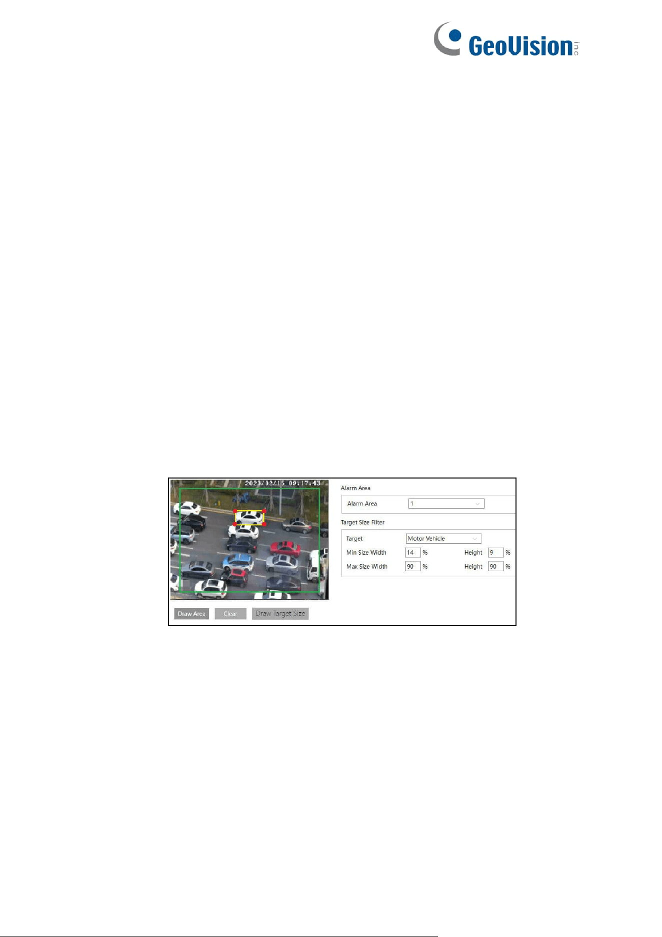
57
For GV-GBL4900 / GBL4911 / GDR4900 / GEB4900 / GVD4910
3. Set alarm lines and target size filter for line crossing detection.
Set the alarm line number and direction. Four lines can be added. Multiple lines cannot be
added simultaneously.
Direction: A←→B, A→B and A←B optional. This indicates the direction of the intruder
who crosses over the alarm line that would trigger the alarm.
A←→B: The alarm will be triggered when the intruder crosses over the alarm line from B
to A or from A to B.
A→B: The alarm will be triggered when the intruder crosses over the alarm line from A to
B.
A←B: The alarm will be triggered when the intruder crosses over the alarm line from B to
A.
Click the “Draw Area” button and then drag the mouse to draw a line in the image. Click
the “Stop Draw” button to stop drawing. Click the “Clear” button to delete the lines. Click
the “Save” button to save the settings.
To set target size filter:
Click “Draw Target Size” to draw the maximum and minimum size of a specific target as
shown below.
Target: Choose “Human”, “Motor Vehicle” or “Motorcycle/Bicycle” as needed.
Green box is the maximum target detection box; yellow box is the minimum target
detection box.
Click the green box to edit the maximum target detection box; click the yellow box to edit
the minimum target detection box.
Drag one of four corners of the green or yellow box to change the box size. The
corresponding size value on the right will be changed too. You can also enter the digital
number to directly change the box size.
Click and drag the green or yellow box to move its position.
Finally, click “Save” to save the settings.
After the target size range is set, only the target whose size is between the minimum
value and the maximum value can be detected.
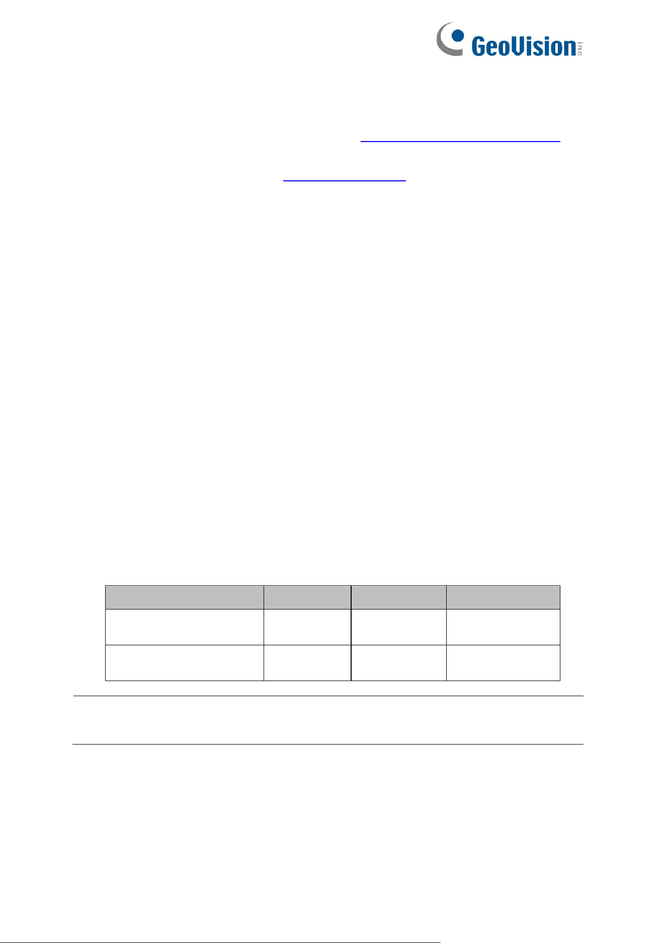
58
4. Click “Save” button to save the settings.
5. Set the schedule of the line crossing detection. The setup steps of schedule are the same
as the motion detection schedule settings (See 4.1.4.2 Schedule Recording Settings).
6. Click “Linkage” to configure the alarm linkage items. The setup steps are the same as
motion detection. Please refer to 4.3.1 Motion Detection for details.
※ Configuration requirements of camera and surrounding area
1. Auto-focusing function should not be enabled for line crossing detection.
2. Avoid the scenes with many trees or the scenes with various light changes (like many
flashing headlights). The ambient brightness of the scenes shouldn’t be too low.
3. Cameras should be mounted at a height of 2.8 meters or above.
4. The recommended depression angle of the camera is from 30° to 45° (See 8. Installation
suggestion below).
5. For pedestrians, their heads and main bodies should be clearly visible on a video. The
detected objects should not be less than 1% of the entire image and the largest sizes of
the detected objects should not be more than 1/8 of the entire image.
For vehicles, the depression angle should not be more than the recommended value.
The sideways or horizontal viewing angle is recommended on a video.
6. Make sure cameras can view objects for at least 2 seconds in the detected area for
accurate detection.
7. Adequate light and clear scenery are crucial for line crossing detection.
8. Please adjust the installation position or focus to meet the requirements of the target
recognition size.
The recommended target recognition size:
Note: The percentage means that a target occupies the percentage of the entire image. For
example, in a 1080p (1920×1080) video image, the minimum resolution of human is 80×160
(w=1920 x 4%=80, h=1920 x 8%=160).
Percentage
Human
Motor Vehicle
Motorcycle/Bicycle
Minimum
(Width × Height)
4% × 8%
8% × 8%
4% × 4%
Maximum
(Width × Height)
50%× 50%
50%× 50%
50%× 50%
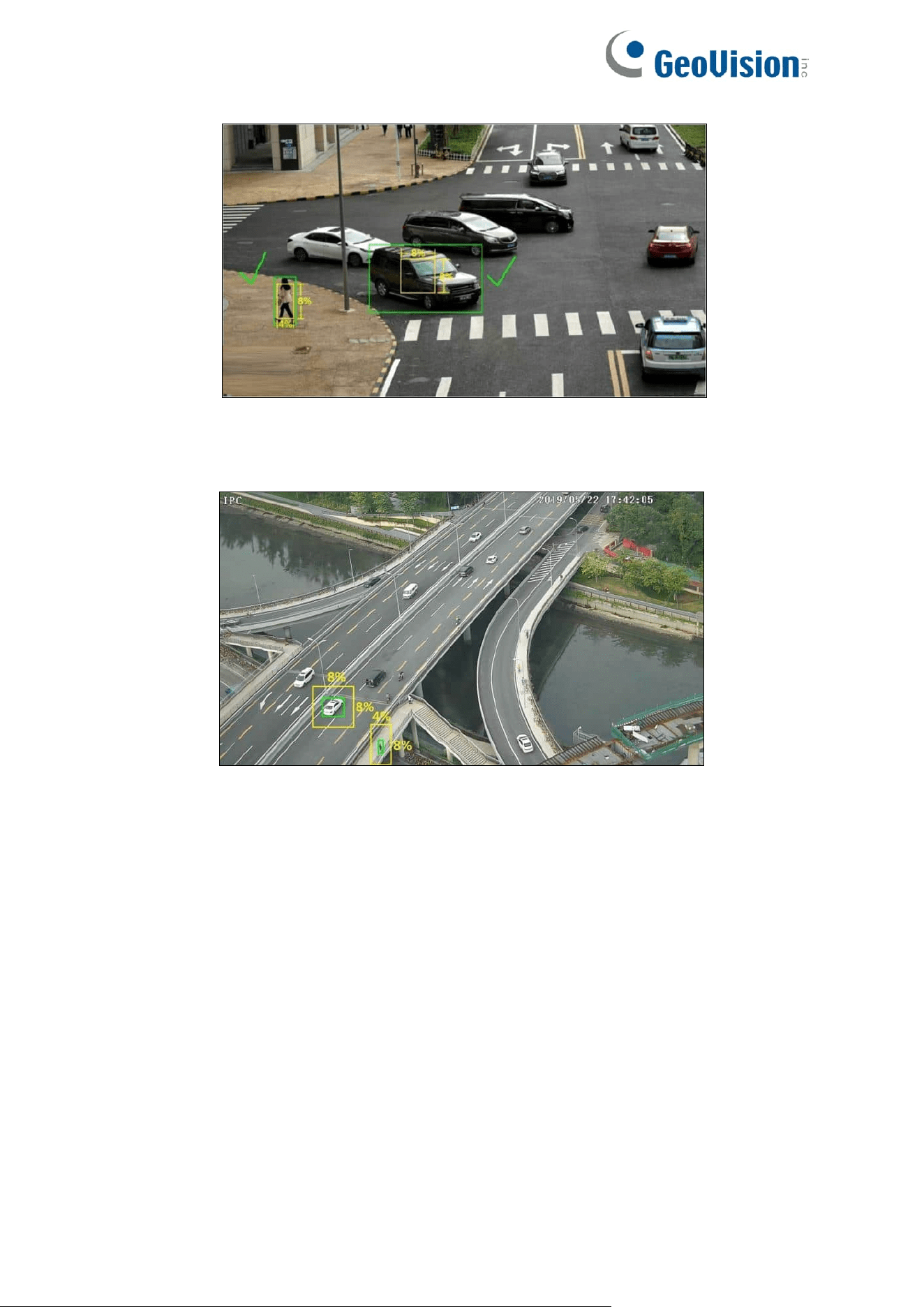
59
Correct example
The target recognition box meets the requirements of the minimum size. The yellow box
stands for the minimum recognition size. The green box stands for the set target box.
Wrong example
The yellow box stands for the minimum recognition size. The green box stands for the set
target box. These two target recognition boxes don’t meet the requirement of the minimum
size. Therefore, you need to adjust the camera position or focus as needed.
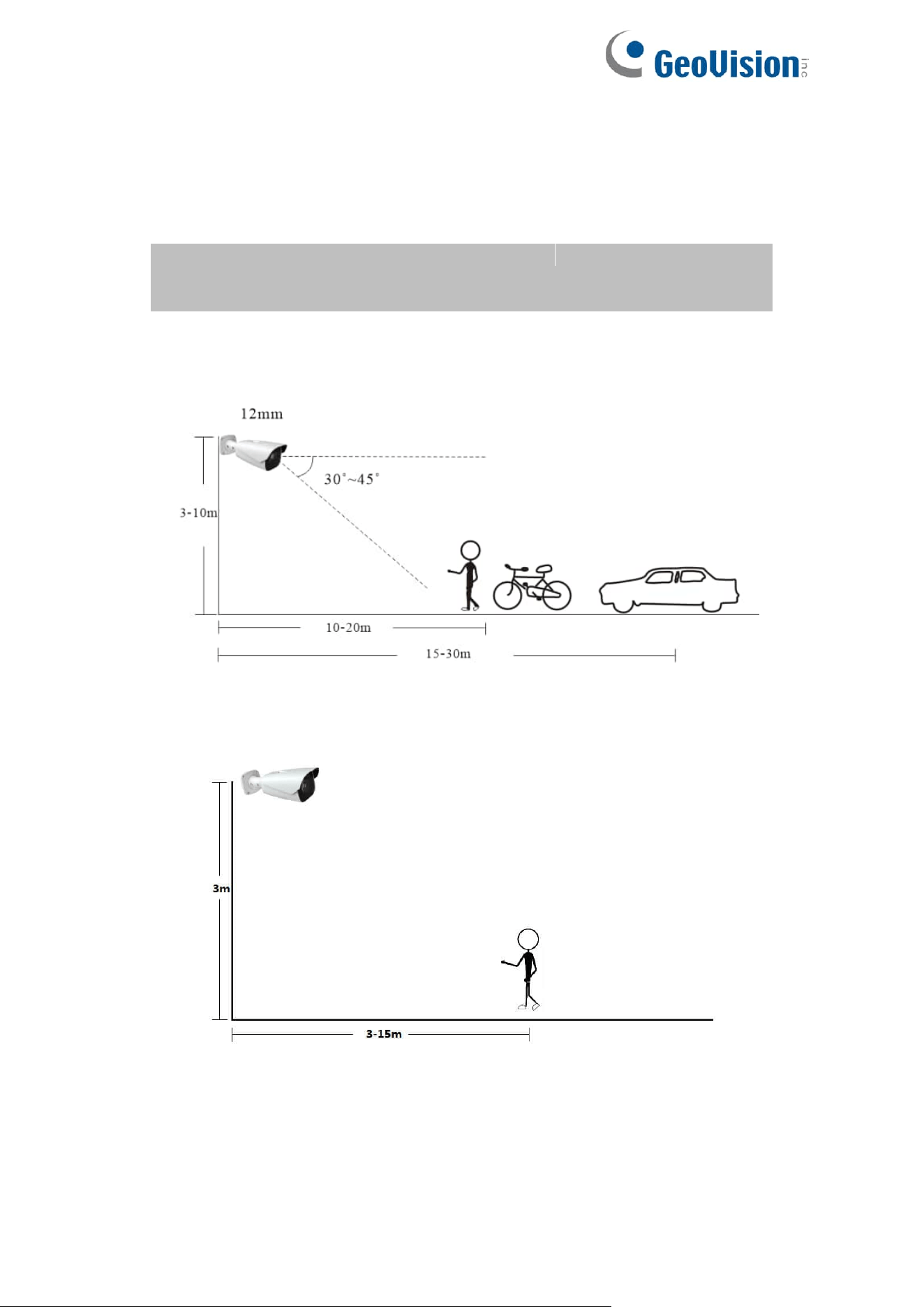
60
9. Installation suggestion:
Outdoor mounting:
The optimal detection distance varies due to different focal length. Please refer to the
following table.
Example for 12 mm focal length
Indoor Mounting:
Focal
Length
Installation
Height(m)
Human/Motorcycle/Bicycle
Motor Vehicle
Maximum
Distance(m)
Optimal
Distance(m)
Maximum
Distance(m)
Optimal
Distance(m)
2.8 mm
3-10
8
4-8
15
10-15
3.6 mm
3-10
10
5-10
20
15-20
12 mm
3-10
25
10~20
35
15~30
22 mm
3-10
45
30~40
70
20~50
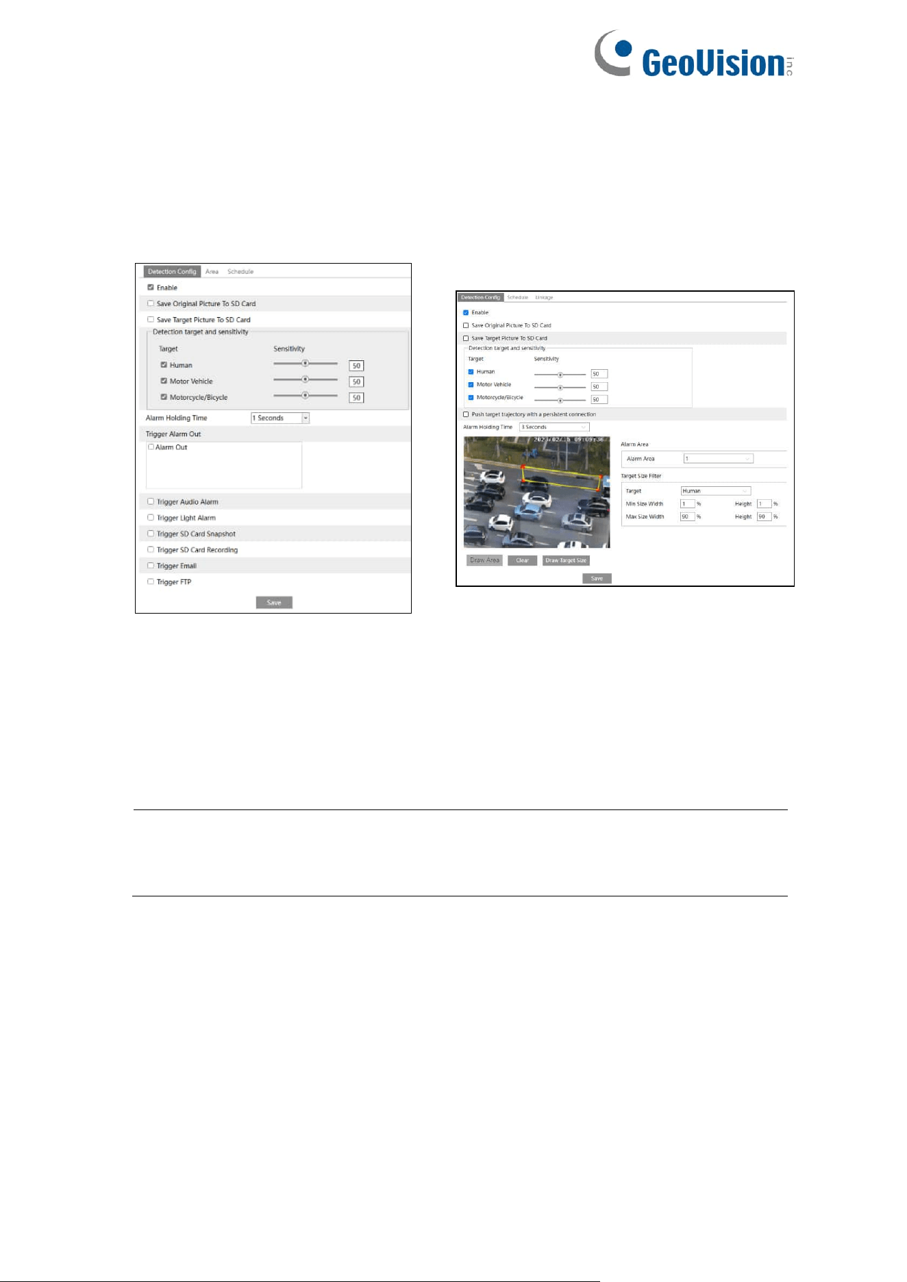
61
4.4.4 Region Entrance
Region Entrance: Alarms will be triggered if the target enters the pre-defined areas.
Go to Config→Event→Region Entrance interface as shown below.
GV-GEBF4911 / GFER6900
GV-GBL4900 / GBL4911 / GDR4900 /
GEB4900 / GVD4910
1. Enable region entrance detection and select the snapshot type and the detection target.
Save Original Picture to SD Card: If it is enabled, the detected original pictures will be
captured and saved to the SD card when the targets intrude into the pre-defined areas.
Save Target Picture to SD Card: If it is enabled, the detected target cutout pictures will
be captured and saved to the SD card when the targets intrude into the pre-defined
areas.
Note: To save snapshots to the local PC, please enable “Local Smart Snapshot
Storage” in the local config interface first. To save snapshots to the SD card, please
install an SD card first.
Detection Target:
⚫ Human: Select it and then alarms will be triggered if someone intrudes into the
pre-defined area.
⚫ Motor Vehicle: Select it and then alarms will be triggered if a vehicle with four or
more wheels (eg. a car, bus or truck) intrudes into the pre-defined area.
⚫ Motorcycle/Bicycle: Select it and then alarms will be triggered if a vehicle with two
wheels (eg. a motorcycle or bicycle) intrudes into the pre-defined area.
All of the three types of objects can be selected simultaneously. Please select the
detection objects as needed. If no object/target is selected, alarms will not be triggered
even if intrusion detection is enabled.
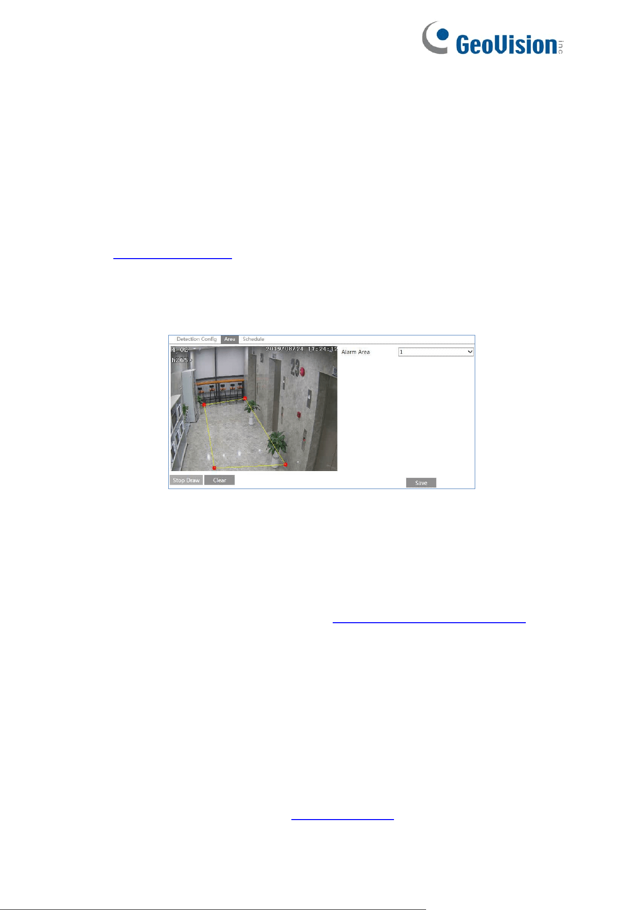
62
Push target trajectory with a persistent connection (for GV-GBL4900 / GBL4911 /
GDR4900 / GEB4900 / GFER6900 / GVD4910): Push target trajectory (moving
coordinate) to API test tool with a persistent connection. If enabled, the system will push
the target trajectory upon detecting a target. If disabled, the system will push the target
trajectory only when triggering line crossing alarm.
2. Set the alarm holding time.
For GV-GEBF4911 / GFER6900
3. Set alarm trigger options. The setup steps are the same as motion detection. Please refer
to 4.3.1 Motion Detection for details.
4. Click the “Save” button to save the settings.
5. Set the alarm area of the region entrance detection. Click the “Area” tab to go to the
interface as shown below.
Set the alarm area number on the right side. Up to 4 alarm areas can be added.
Click the “Draw Area” button and then click around the area where you want to set as the
alarm area in the image on the left side (the alarm area should be a closed area). Click
the “Stop Draw” button to stop drawing. Click the “Clear” button to delete the alarm area.
Click the “Save” button to save the settings.
6. Set the schedule of the region intrusion detection. The setup steps of the schedule are
the same as schedule recording setup (See 4.1.4.2 Schedule Recording Settings).
For GV-GBL4900 / GBL4911 / GDR4900 / GEB4900 / GVD4910
3. Set alarm areas and target size filter for region intrusion detection.
4. Set the alarm area number. Four alarm areas can be added.
5. Click the “Draw Area” button and then click around the area where you want to set as the
alarm area in the image (the alarm area should be a closed area). Click the “Stop Draw”
button to stop drawing. Click the “Clear” button to delete the alarm area. Click the “Save”
button to save the settings.
Target size filter setup: The setup steps of the target size filter are the same as line
crossing target size filter setup (See 4.4.3 Line Crossing).

63
6. Set the schedule of the region entrance detection. The setup steps of schedule are the
same as the motion detection schedule settings (See 4.1.4.2 Schedule Recording
Settings).
7. Click “Linkage” to configure the alarm linkage items. The setup steps are the same as
motion detection. Please refer to 4.3.1 Motion Detection for details.
※ Configuration requirements of camera and surrounding area
The requirements are similar to line crossing detection. Please refer to Configuration
requirements of camera and surrounding area in 4.4.3 Line Crossing for details.
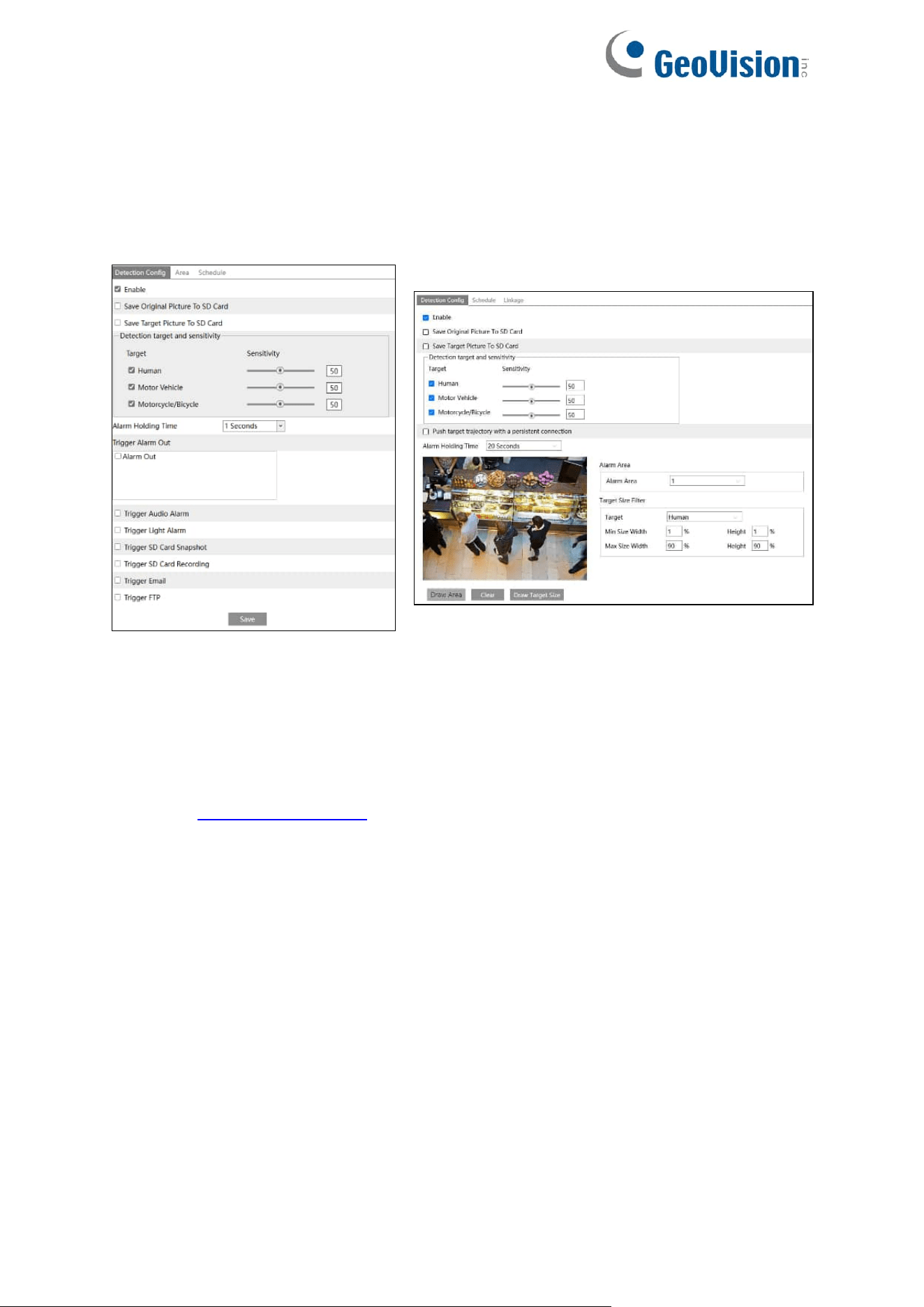
64
4.4.5 Region Exiting
Region Exiting: Alarms will be triggered if the target exits from the pre-defined areas.
Go to Config→Event→Region Exiting interface as shown below.
GV-GEBF4911 / GFER6900
GV-GBL4900 / GBL4911 / GDR4900 / GEB4900 /
GVD4910
1. Enable region exiting detection and select the snapshot type and the detection target.
2. Set the alarm holding time and alarm trigger options.
3. Set the alarm area of the region exiting detection.
4. Set the schedule of the region exiting detection.
The setup steps of the region exiting detection are the same as the region entrance detection
setup (See 4.4.4 Region Entrance for details).
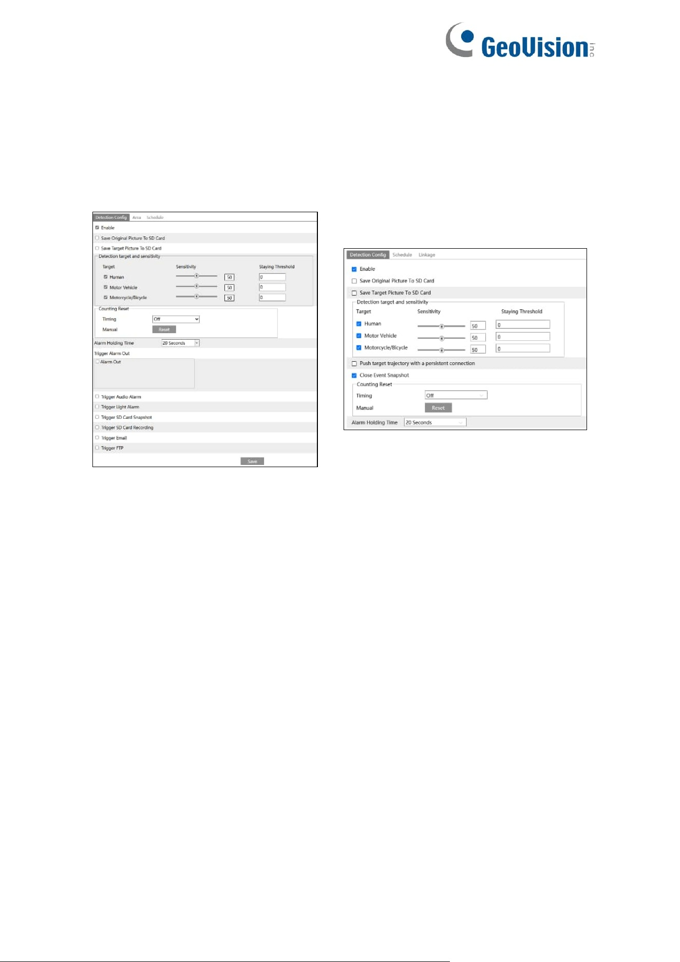
65
4.4.6 Target Counting by Line
This function is to calculate the number of the people or vehicles crossing the alarm line
through detecting, tracking and counting the shapes of the people or vehicles.
1. Go to Config→Event→Target Counting by Line as shown below.
GV-GEBF4911 / GFER6900
GV-GBL4900 / GBL4911 / GDR4900 /
GEB4900 / GVD4910
2. Enable Target Counting by Line, and select the snapshot type and the detection target.
Detection Target: Select the target to calculate. Human, motor vehicle and
motorcycle/bicycle can be selected.
Staying Threshold: When the targets (human/vehicle) staying in the specified area
exceed the threshold, alarms will be triggered.
Counting Reset: The current number of the target counting can be reset. You can
choose to reset the counting daily, weekly or monthly. Click “Reset” to manually reset the
current number of crossing line people/car/bike counting.
Push target trajectory with a persistent connection (for GV-GBL4900 / GBL4911 /
GDR4900 / GEB4900 / GFER6900 / GVD4910): Push target trajectory (moving
coordinate) to API test tool with a persistent connection. If enabled, the system will push
the target trajectory upon detecting a target. If disabled, the system will push the target
trajectory only when triggering Target Counting by Line.
Close Event Snapshot (for GV-GBL4900 / GBL4911 / GDR4900 / GEB4900 /
GFER6900 / GVD4910): If enabled, the pictures that are captured when counting targets
will be neither saved to an SD card/local PC nor pushed to the NVR/APP/platform/….
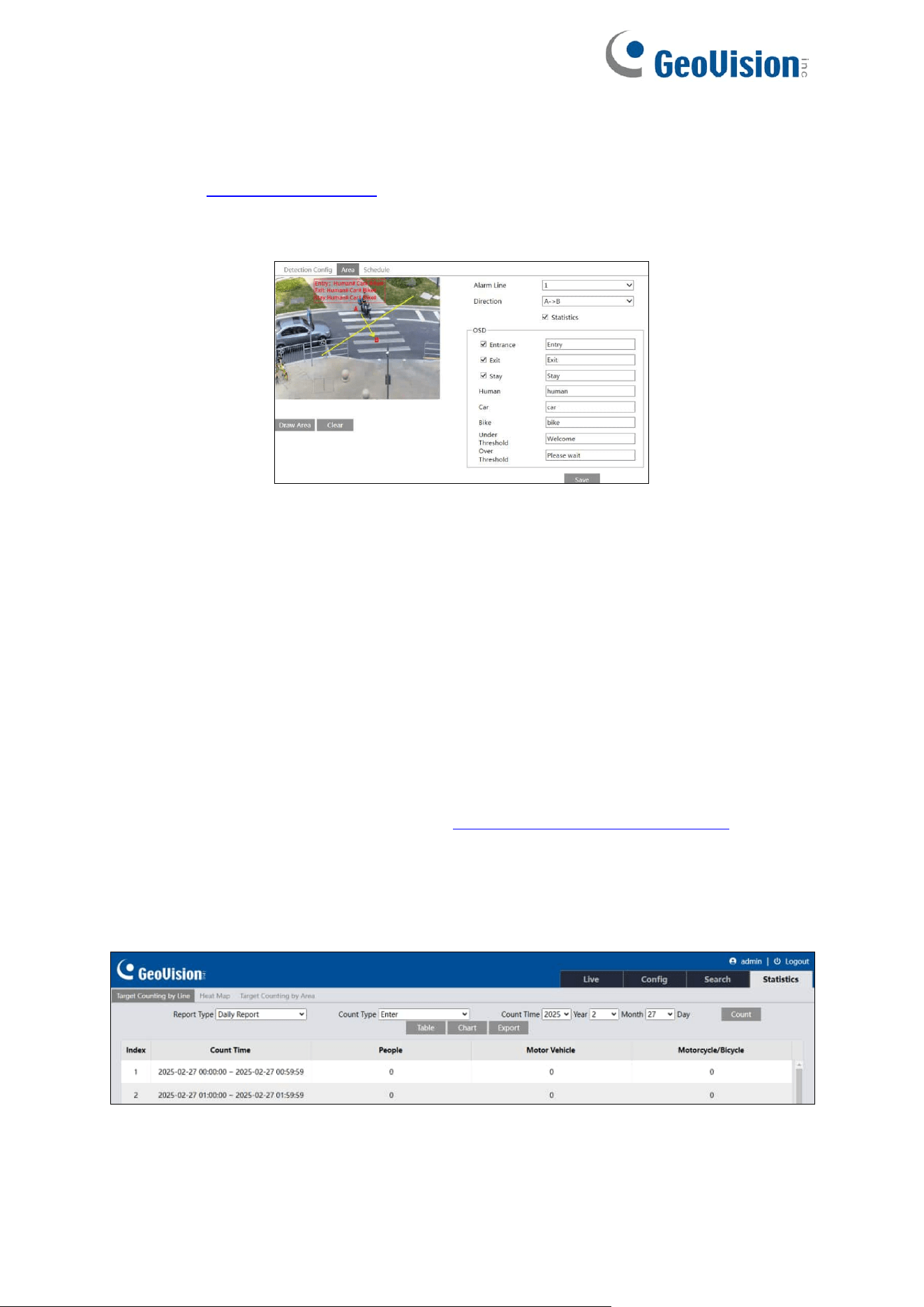
66
For GV-GEBF4911 / GFER6900
3. Set the alarm trigger options. The setup steps are the same as motion detection. Please
refer to 4.3.1 Motion Detection for details.
4. Set the alarm line. Click the “Area” tab to go to the interface as shown below.
Set the alarm line number and direction. Only one alarm line can be added.
Direction:A→B and A←B can be optional. The direction of the arrow is entrance.
Statistics: If enabled, you can see the statistical information in the live view interface. If
disabled, the statistical information will not be displayed in the live view interface.
The statistical OSD information can be customized as needed.
Click the “Draw Area” button and then drag the mouse to draw a line in the image. Check
“Statistics” and then move the red box to change the position of the statistical information
displayed on the screen. Click the “Stop Draw” button to stop drawing. Click the “Clear”
button to delete the lines.
Click the “Save” button to save the settings.
5. Set the schedule of the Target Counting by Line. The setup steps of the schedule are the
same as schedule recording setup (See 4.1.4.2 Schedule Recording Settings).
6. View the statistical information in the live view interface. (For GV-GFER6900, click the
Fisheye live preview mode in the live view interface.)
7. View the statistical information of the Target Counting by Line. Click “Statistics” to enter
the following interface.
Select the report type. Daily report, weekly report, monthly report and annual report are
selectable.
Select the count type. Enter or leave can be optional.
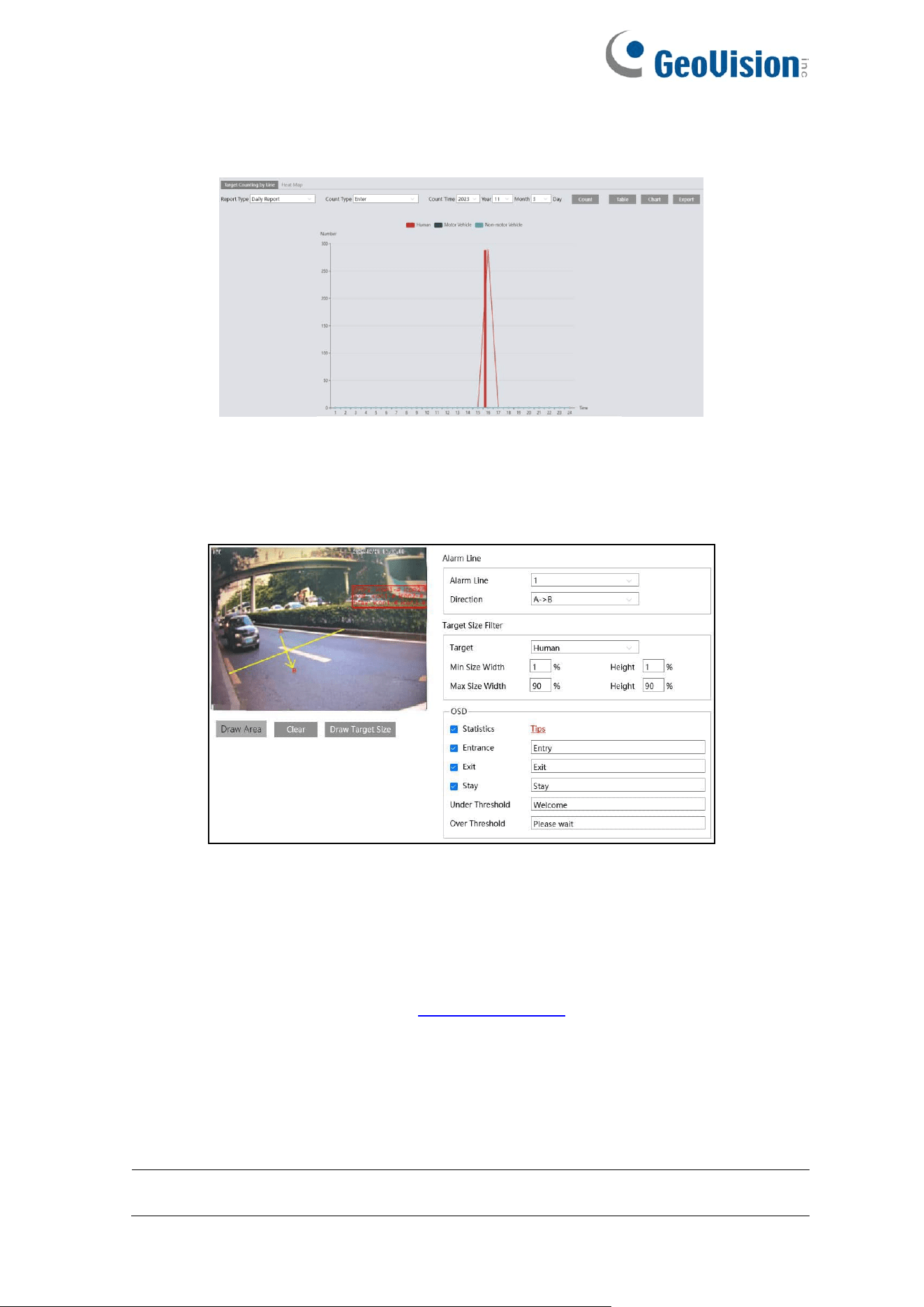
67
Select the start time and then click “Count”. Then the counting result will display in the
statistic result area. Click Table or Chart to display the result in different way.
GV-GBL4900 / GBL4911 / GDR4900 / GEB4900 / GVD4910
3. Set the alarm holding time.
4. Set alarm lines and target size filter.
Set the alarm line number and direction. Only one alarm line can be added.
Direction: A→B and A←B can be optional. The direction of the arrow is entrance.
Click the “Draw Area” button and then drag the mouse to draw a line in the image. Click
the “Clear” button to delete the lines.
Target size filter setup: The setup steps of the target size filter are the same as line
crossing target size filter setup (See 4.4.3 Line Crossing for details).
Statistics: If enabled, you can see the statistical information in the live view interface. If
disabled, the statistical information will not be displayed in the live view interface.
Check “Statistics” and then move the red box to change the position of the statistical
information displayed on the screen.
The statistical OSD information can be customized as needed.
Note: When target counting by line and by area are enabled simultaneously, the OSD
position shown in the image depends on the OSD position of target counting by area.
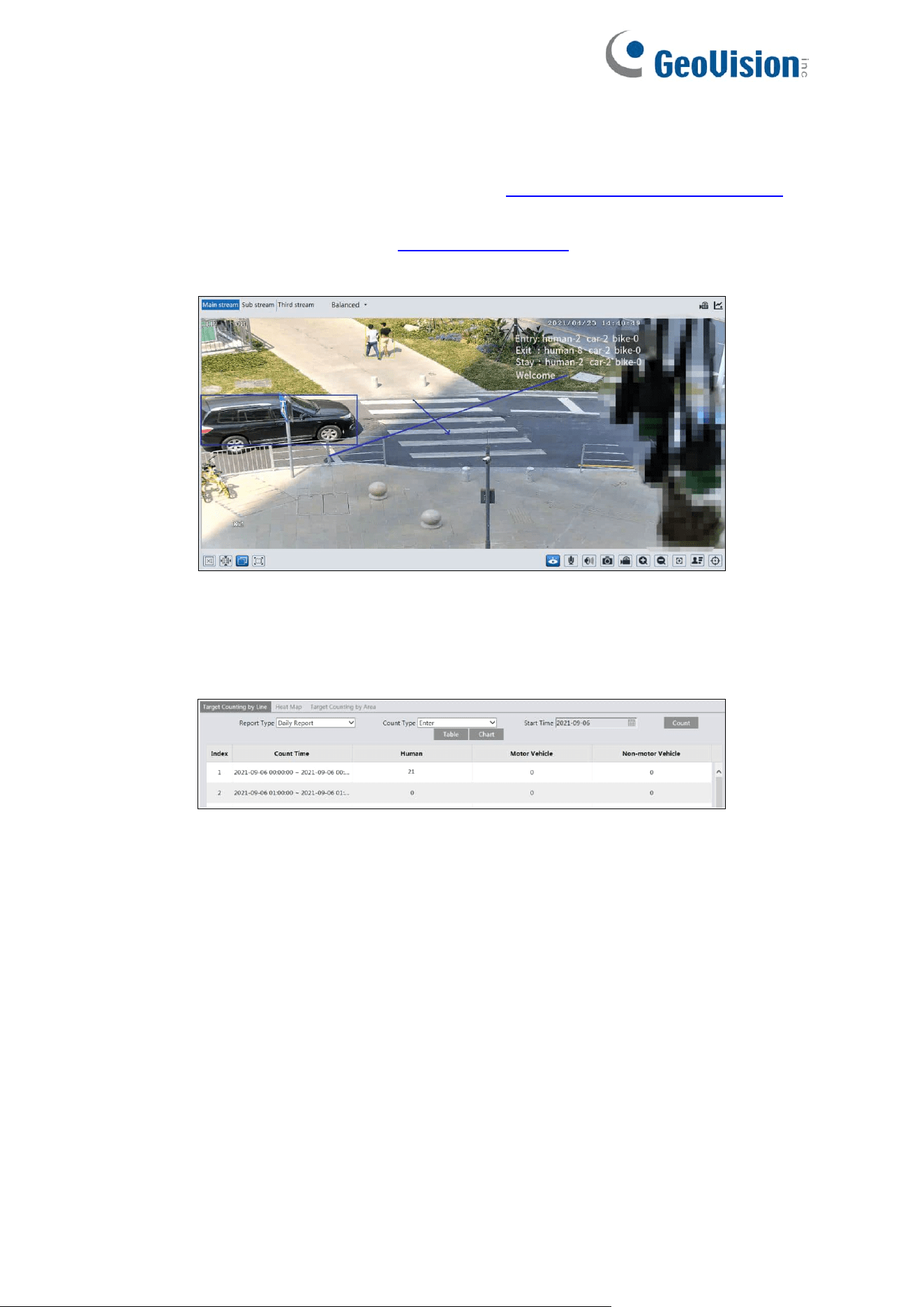
68
Click “Save” button to save the settings.
5. Set the schedule of the target counting by line. The setup steps of schedule are the same
as the motion detection schedule settings (See 4.1.4.2 Schedule Recording Settings).
6. Click “Linkage” to configure the alarm linkage items. The setup steps are the same as
motion detection. Please refer to 4.3.1 Motion Detection for details.
7. View the statistical information in the live view interface.
8. View the statistical information of target counting by line. Click Statistics→Target
Counting by Line (GV-GEBF4911 / GFER6900) / Chart→Target Counting by Line
(GV-GBL4900 / GBL4911 / GDR4900 / GEB4900 / GVD4910) to enter the following
interface.
Select the Report Type. Daily Report, Weekly Report, Monthly Report, and Annual Report
are selectable.
Select the Count Type. Enter or leave can be optional.
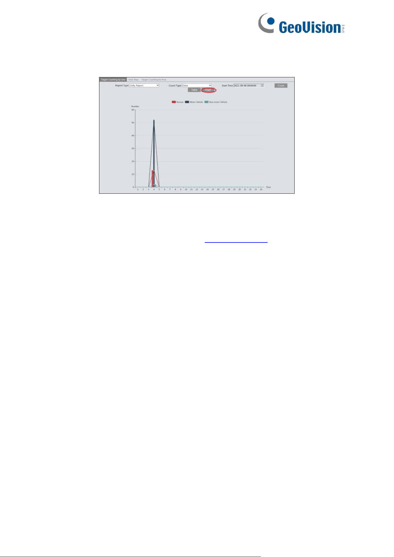
69
Select the start time and then click “Count”. Then the counting result will display in the
statistic result area. Click Table or Statistics to display the result in different way.
※ Configuration requirements of camera and surrounding area
The requirements are similar to line crossing detection. Please refer to Configuration
requirements of camera and surrounding area in 4.4.3 Line Crossing for details.
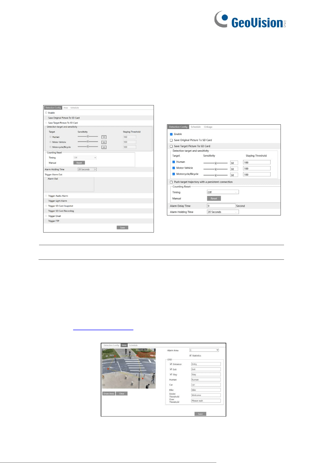
70
4.4.7 Target Counting by Area
This function is to calculate the number of the people or vehicles intruding into the pre-defined
area through detecting, tracking and counting the shapes of the people or vehicles.
Go to Config→Event→Target Counting by Area as shown below.
GV-GEBF4911
GV-GBL4900 / GBL4911 / GDR4900 /
GEB4900 / GVD4910
Note: The Target Counting by Area function is not applicable to GV-GFER6900.
1. Enable target counting by area, select the snapshot type, the detection target, counting
reset.
For GV-GEBF4911
2. Set up alarm triggers. The setup steps are the same as the target counting by line. Please
refer to 4.3.1 Motion Detection for details.
3. Set the statistic area. Click the “Area” tab to go to the interface as shown below.
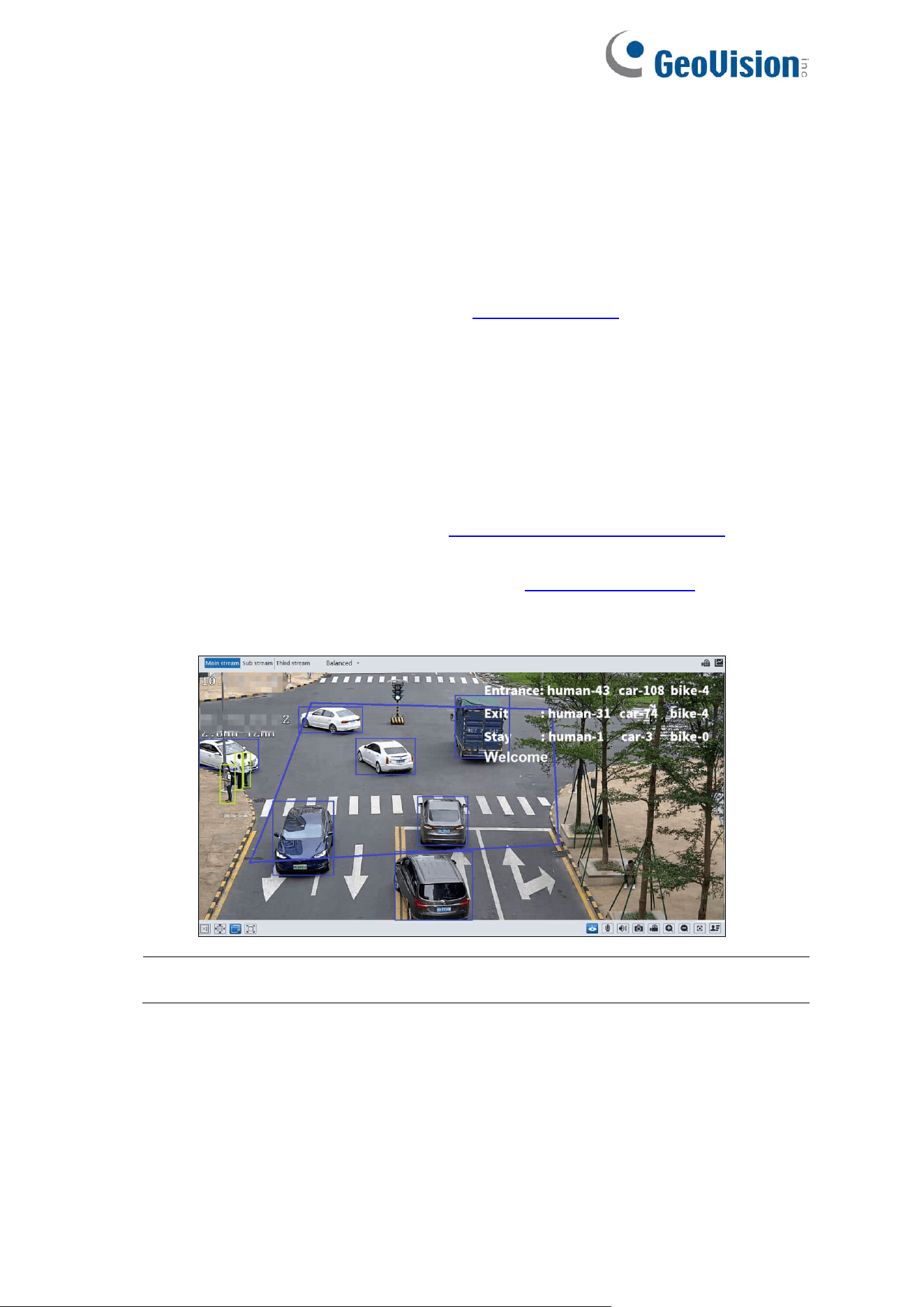
71
Select the alarm area number on the right side. Only one alarm area can be added.
Click the “Draw Area” button and then click around the area where you want to set as the
alarm area in the image on the left side (the alarm area should be a closed area). Click
the “Stop Draw” button to stop drawing. Click the “Clear” button to delete the alarm area.
Click the “Save” button to save the settings.
Push target trajectory with a persistent connection (for GV-GBL4900 / GBL4911 /
GDR4900 / GEB4900 / GVD4910): The setup steps of the target size filter are the same
as line crossing target size filter setup (See 4.4.3 Line Crossing for details).
Statistics (for GV-GBL4900 / GBL4911 / GDR4900 / GEB4900 / GVD4910): If enabled,
you can see the statistical information in the live view interface. If disabled, the statistical
information will not be displayed in the live view interface.
Check “Statistics” and then move the red box to change the position of the statistical
information displayed on the screen.
The statistical OSD information can be customized as needed.
4. Set the schedule of the target counting by area. The setup steps of the schedule are the
same as schedule recording setup (See 4.1.4.2 Schedule Recording Settings).
5. To set up alarm triggers for GV-GDR4900 / GEB4900, click “Linkage”. The setup steps
are the same as motion detection. Please refer to 4.3.1 Motion Detection for details.
6. View the statistical information in the live view interface.
Note: When target counting by line and by area are enabled simultaneously, the OSD
position shown in the image depends on the OSD position of target counting by area.
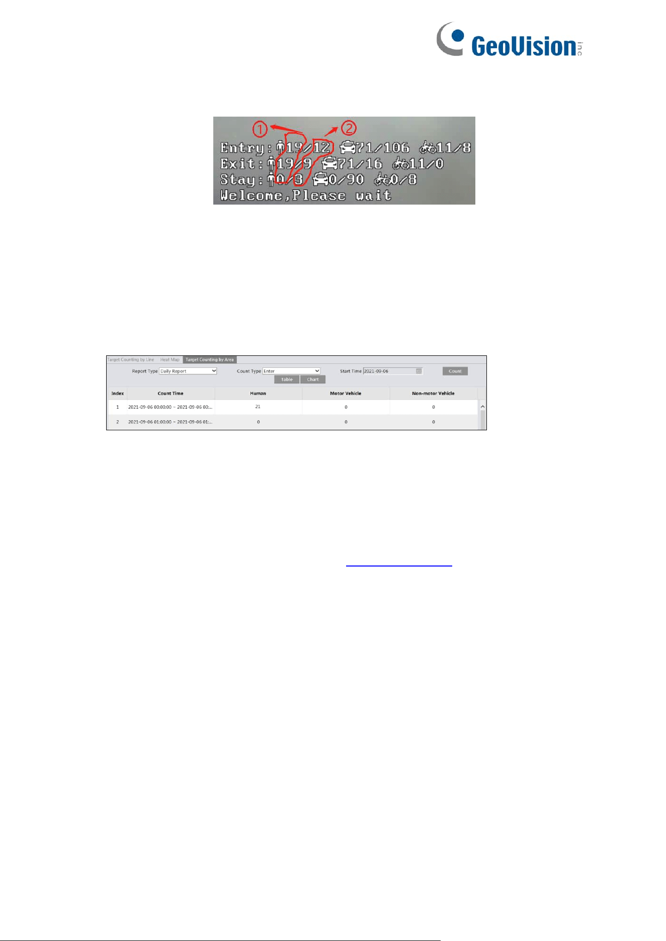
72
Only for GV-GBL4900 / GBL4911 / GDR4900 / GEB4900 / GVD4910
○1 : the statistical number of target counting by area
○2 : the statistical number of target counting by line
Each line of the above OSD information (including OSD content, colon, slashes and
images) cannot exceed 37 characters, or some data will not be displayed completely.
7. View the statistical information of target counting by area. Click Statistics→Target
Counting by Area (GV-GEBF4911) / Chart→ Target Counting by Area (GV-GBL4900 /
GBL4911 / GDR4900 / GEB4900 / GVD4910) to enter the following interface.
Please select Report Type, Count Type and Count Time as needed. Then click “Count” to
search the statistic result. Click “Statistics” to view the statistic result intuitively.
※ Configuration requirements of camera and surrounding area
The requirements are similar to line crossing detection. Please refer to Configuration
requirements of camera and surrounding area in 4.4.3 Line Crossing for details.
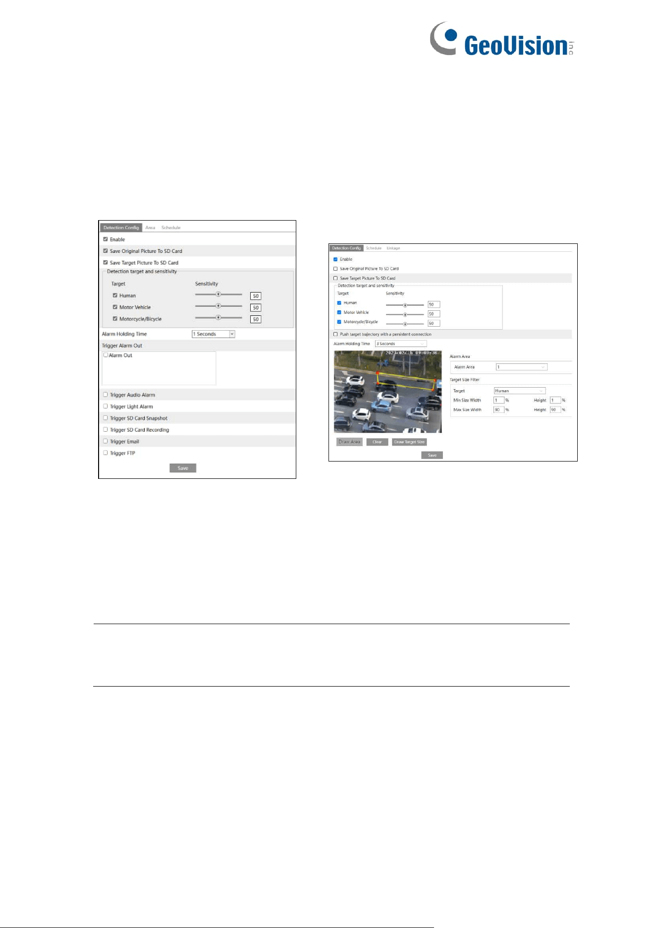
73
4.4.8 Region Intrusion
Region Intrusion: Alarms will be triggered if the target intrudes into the pre-defined areas.
This function can be applicable to important supervision places, danger areas and prohibited
areas, like military administrative zones, high danger areas, no man’s areas, etc.
Go to Config→Event→Region Intrusion interface as shown below.
GV-GEBF4911 / GFER6900
GV-GBL4900 / GBL4911 / GDR4900 /
GEB4900 / GVD4910
1. Enable intrusion detection and select the snapshot type and the detection target.
Save Original Picture to SD Card: If it is enabled, the detected original pictures will be
captured and saved to the SD card when the targets intrude into the pre-defined areas.
Save Target Picture to SD Card: If it is enabled, the detected target cutout pictures will
be captured and saved to the SD card when the targets intrude into the pre-defined
areas.
Note: To save snapshots to the local PC, please enable “Local Smart Snapshot
Storage” in the local config interface first. To save snapshots to the SD card, please
install an SD card first.
Detection Target:
⚫ Human: Select it and then alarms will be triggered if someone intrudes into the
pre-defined area.
⚫ Motor Vehicle: Select it and then alarms will be triggered if a vehicle with four or
more wheels (e.g., a car, bus or truck) intrudes into the pre-defined area.
⚫ Motorcycle/Bicycle: Select it and then alarms will be triggered if a vehicle with two
wheels (e.g., a motorcycle or bicycle) intrudes into the pre-defined area.
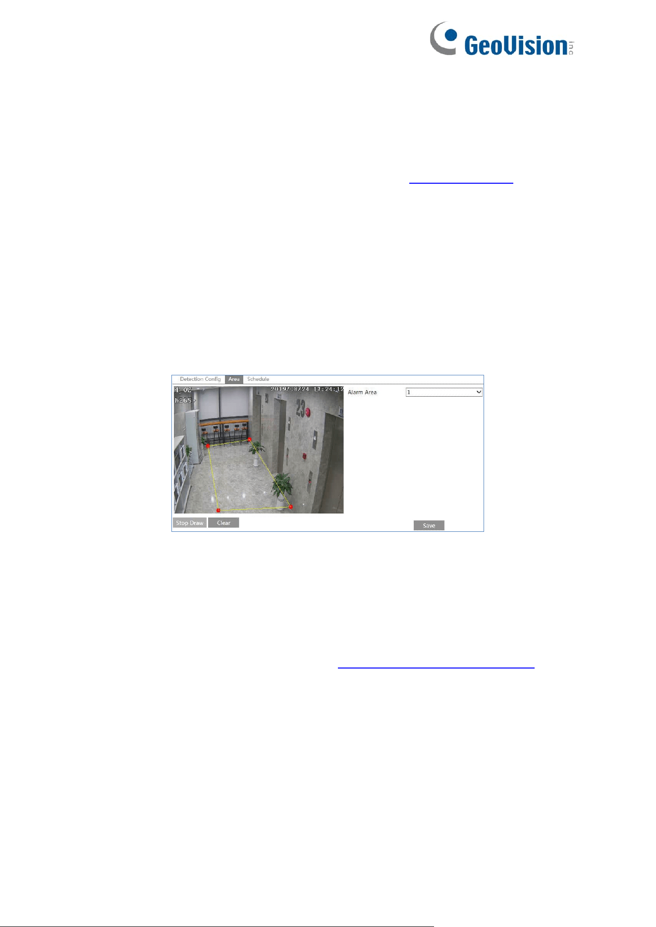
74
All of the three types of objects can be selected simultaneously. Please select the
detection objects as needed. If no object/target is selected, alarms will not be triggered
even if intrusion detection is enabled.
Push target trajectory with a persistent connection (for GV-GBL4900 / GBL4911 /
GDR4900 / GEB4900 / GFER6900 / GVD4910): The setup steps of the target size filter
are the same as line crossing target size filter setup (See 4.4.3 Line Crossing for details).
2. Set the alarm holding time.
For GV-GEBF4911 / GFER6900
3. Set alarm trigger options. The setup steps are the same as motion detection. Please refer
to motion detection chapter for details.
4. Click the “Save” button to save the settings.
5. Set the alarm area of the region intrusion detection. Click the “Area” tab to go to the
interface as shown below.
Set the alarm area number on the right side. Up to 4 alarm areas can be added.
Click the “Draw Area” button and then click around the area where you want to set as the
alarm area in the image on the left side (the alarm area should be a closed area). Click
the “Stop Draw” button to stop drawing. Click the “Clear” button to delete the alarm area.
Click the “Save” button to save the settings.
6. Set the schedule of the region intrusion detection. The setup steps of the schedule are
the same as schedule recording setup (See 4.1.4.2 Schedule Recording Settings).
7. In the live view interface, click “Fisheye” (ceiling mounting mode) to view region intrusion
detection. (This step is only applicable to GV-GFER6900)

75
For GV-GBL4900 / GBL4911 / GDR4900 / GEB4900 / GVD4910
3. Set alarm areas and target size filter for region intrusion detection.
4. Set the alarm area number. Four alarm areas can be added.
Click the “Draw Area” button and then click around the area where you want to set as the
alarm area in the image (the alarm area should be a closed area). Click the “Stop Draw”
button to stop drawing. Click the “Clear” button to delete the alarm area. Click the “Save”
button to save the settings.
Target size filter setup: The setup steps of the target size filter are the same as line
crossing target size filter setup (See 4.4.3 Line Crossing for details).
5. Click “Save” button to save the settings.
6. Set the schedule of region intrusion detection. The setup steps of the schedule are the
same as schedule recording setup (See 4.1.4.2 Schedule Recording Settings).
7. To set up alarm triggers, click “Linkage”. The setup steps are the same as motion
detection. Please refer to 4.3.1 Motion Detection for details.
※ Configuration requirements of camera and surrounding area
The requirements are similar to line crossing detection. Please refer to Configuration
requirements of camera and surrounding area in 4.4.3 Line Crossing for details.
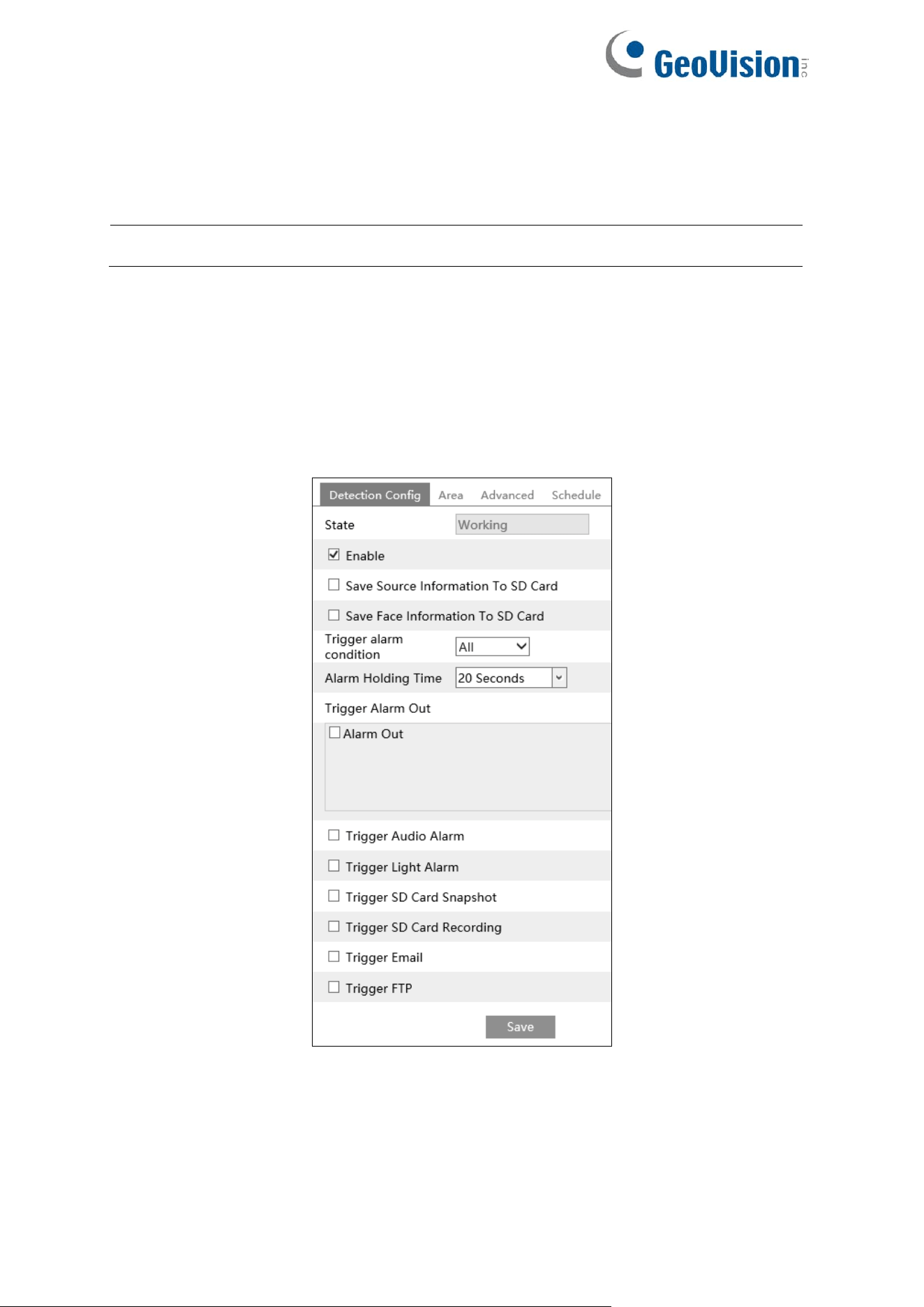
76
4.4.9 Face Detection
Face detection function is to detect the face appearing in the surveillance scene. Alarms will
be triggered when a face is detected.
Note: The Face Detection function is not applicable to GV-GFER6900.
The setting steps are as follows:
For GV-GEBF4911
1. Go to Config→Event→Face Detection as shown below.
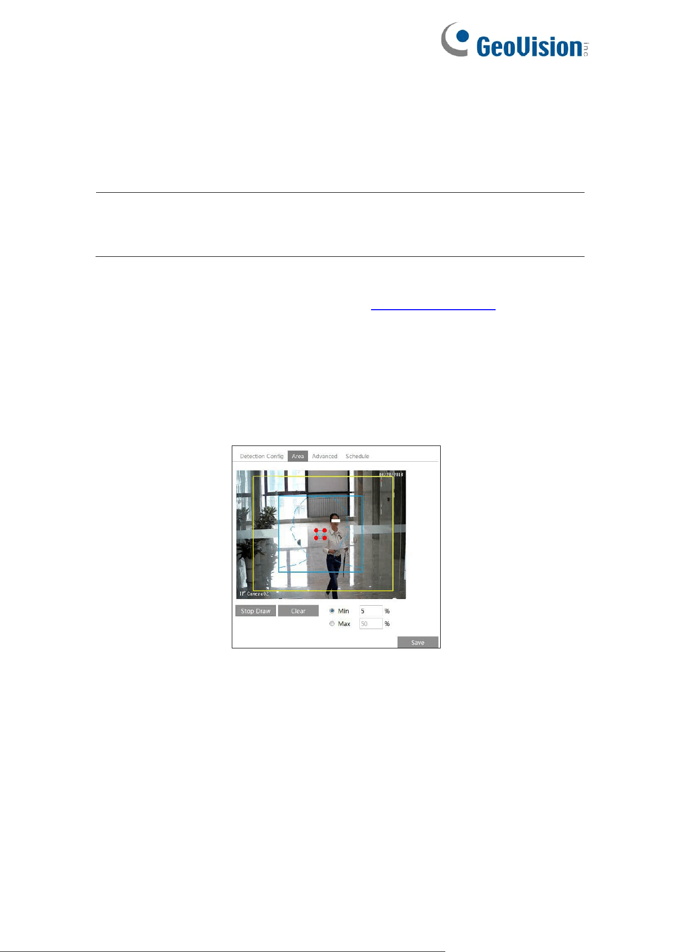
77
2. Enable the face detection function.
Save Source Information to SD Card: if checked, the whole picture will be saved to the
local PC or SD card when detecting a face.
Save Face Information to SD Card: if checked, the captured face picture will be saved
to the local PC or SD card when detecting a face.
Note: To save images to the local PC, please enable the local smart snapshot storage
first (Config→System→Local Config). To save images to the SD card, please install an
SD card first.
3. Set alarm holding time and alarm trigger options. The alarm trigger setup steps are the
same as motion detection setup. Please refer to 4.3.1 Motion Detection chapter for
details.
Trigger alarm condition: all or mask off can be selectable.
⚫ All: Alarms will be triggered when the camera detects a face (with/without a mask).
⚫ Mask off: Alarms will be triggered when the detected person is not wearing a mask on
the face.
4. Set alarm detection area.
Click “Draw Area” and drag the border lines of the rectangle to modify its size. Move the
rectangle to change its position. Click “Stop Draw” to stop drawing the area. Click “Clear”
to clear the area. Then set the detectable face size by defining the maximum value and
the minimum value (The default size range of a single face image occupies from 3% to
50% of the entire image).
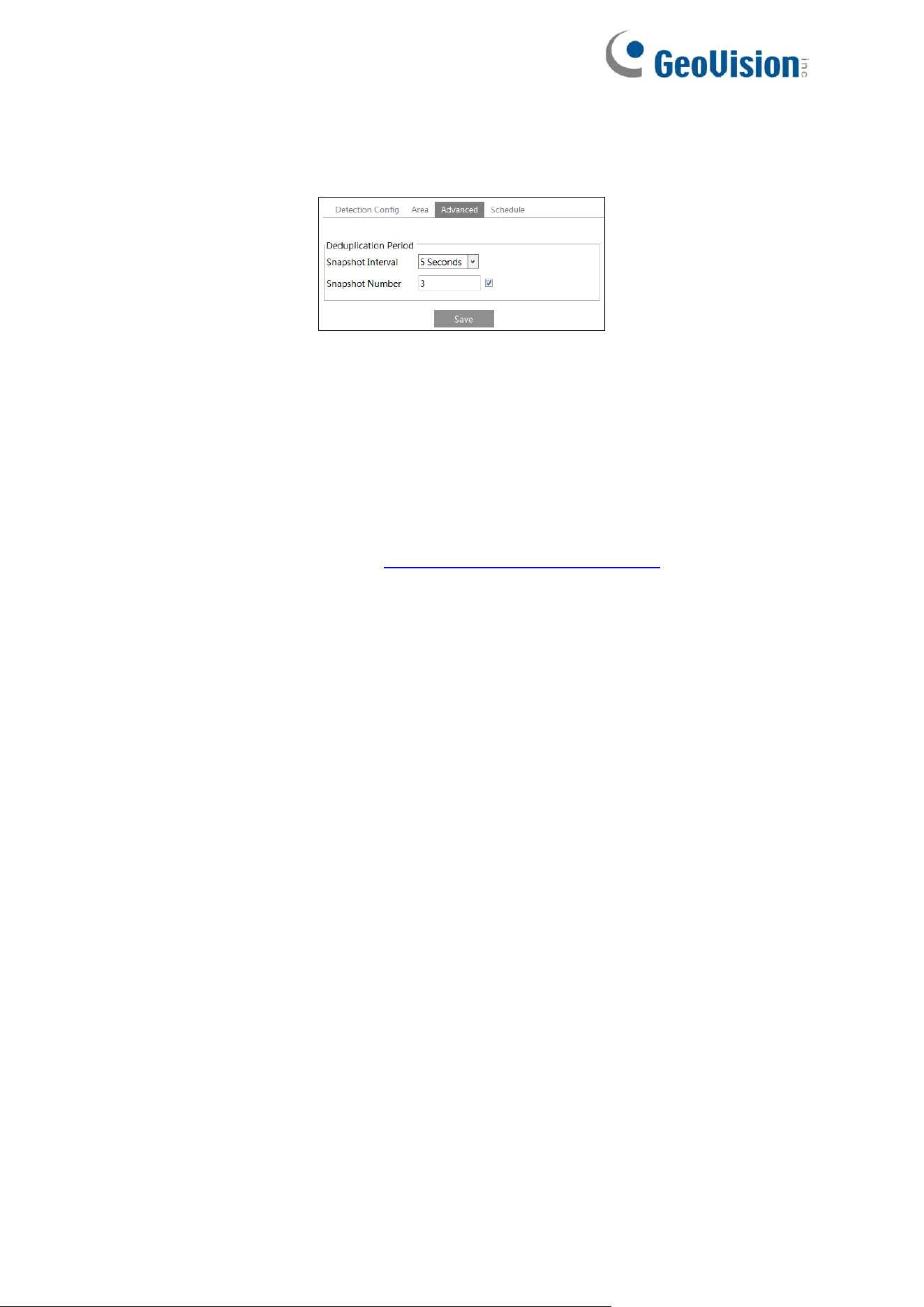
78
5. Advanced settings. Choose the snapshot interval and number as needed to avoid
capturing multiple similar pictures in a very short period of time.
Snapshot Interval: If 5 seconds is selected, the camera will capture the same target
once every 5 seconds during its continuous tracking period.
Snapshot Number: If the snapshot number is enabled and set (eg. 3), the camera will
capture the same target once every 5 seconds and it will capture this target 3 times at
most during its continuous tracking period. If the snapshot number is disabled, the
camera will capture the same target once every 5 seconds until the target disappears in
the detected area.
6. Set the schedule of the face detection. The setup steps of the schedule are the same as
schedule recording setup (See 4.1.4.2 Schedule Recording Settings).
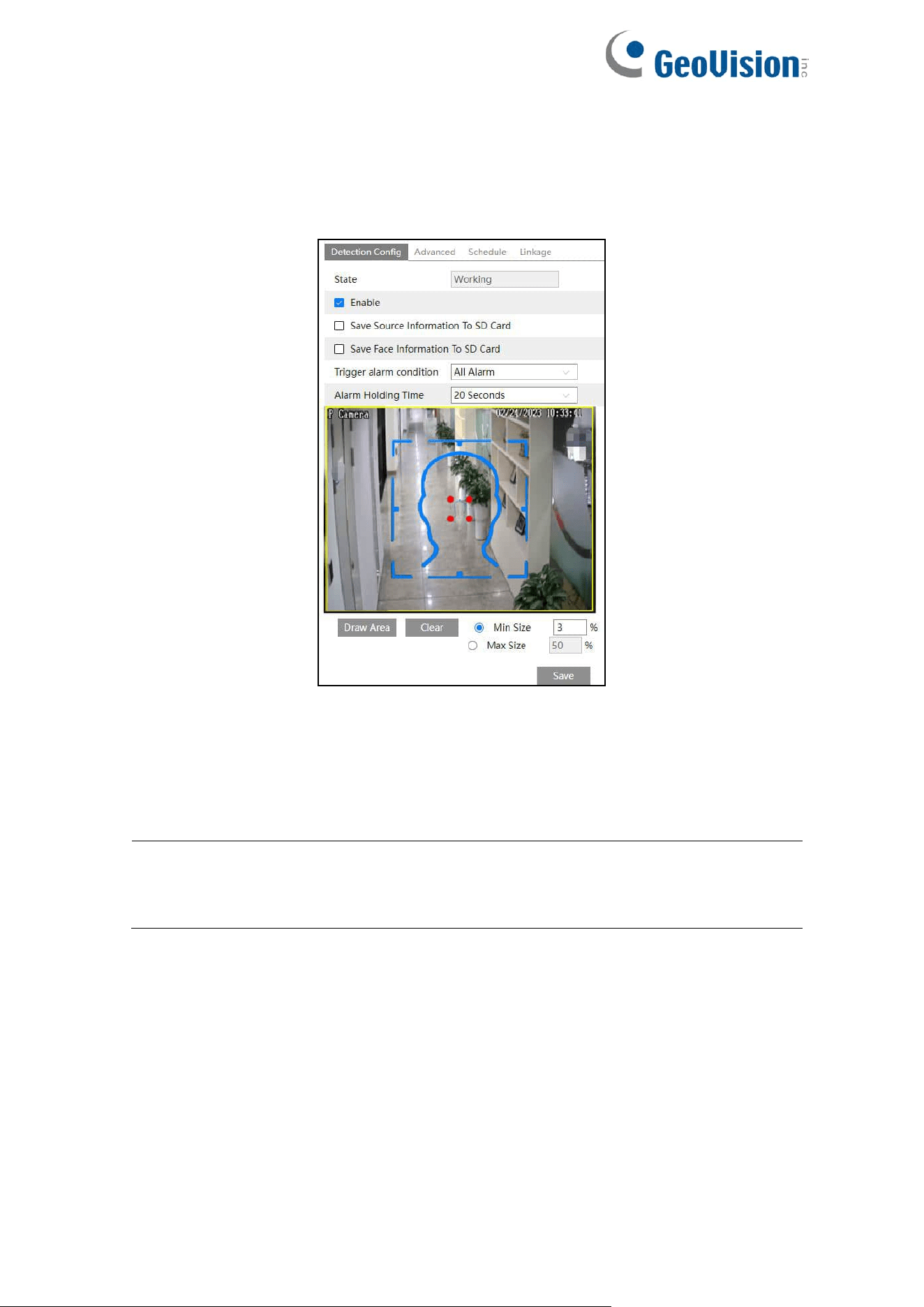
79
For GV-GBL4900 / GBL4911 / GDR4900 / GEB4900 / GVD4910
1. Click Config→Event→Enable Event. Select the face event and then save the setting.
After the camera restarts successfully, you can view the face detection menu.
2. Go to Config→Event→Face Detection as shown below.
3. Enable the face detection function.
Save Source Information to SD Card: if checked, the whole picture will be saved to SD
card when detecting a face.
Save Face Information to SD Card: if checked, the captured face picture will be saved to
SD card when detecting a face.
Note: To save images to the local PC, please enable the local smart snapshot storage
first (Config→System→Local Config). To save images to the SD card, please install an
SD card first.
4. Set alarm condition and the alarm holding time.
Trigger alarm condition: all or mask off can be selectable.
All: Alarms will be triggered when the camera detects a face (with/without a mask).
Mask off: Alarms will be triggered when the detected person is not wearing a mask on
the face.
5. Set alarm detection area.
Click “Draw Area” and drag the border lines of the rectangle to modify its size. Move the
rectangle to change its position. Click “Stop Draw” to stop drawing the area. Click “Clear”
to clear the area. Then set the detectable face size by defining the maximum value and
the minimum value (The default size range of a single face image occupies from 3% to
50% of the entire image).
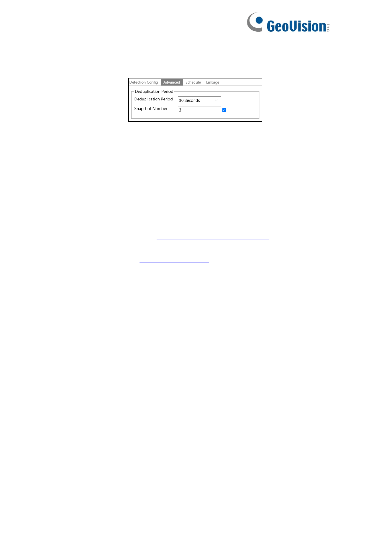
80
6. Advanced settings. Choose the snapshot interval and number as needed to avoid
capturing multiple similar pictures in a very short period of time.
Deduplication Period: If 30 seconds is selected, the camera will capture the same target
once every 30 seconds during its continuous tracking period.
Snapshot Number: If the snapshot number is enabled and set (eg. 3), the camera will
capture the same target once every 30 seconds and it will capture this target 3 times at
most during its continuous tracking period. If the snapshot number is disabled, the
camera will capture the same target once every 30 seconds until the target disappears in
the detected area.
7. Advanced settings. Choose the snapshot interval and number as needed to avoid
capturing multiple similar pictures in a very short period of time.
8. Set the schedule of face detection. The setup steps of the schedule are the same as
schedule recording setup (See 4.1.4.2 Schedule Recording Settings).
9. To set up alarm triggers, click “Linkage”. The setup steps are the same as motion
detection. Please refer to 4.3.1 Motion Detection for details.
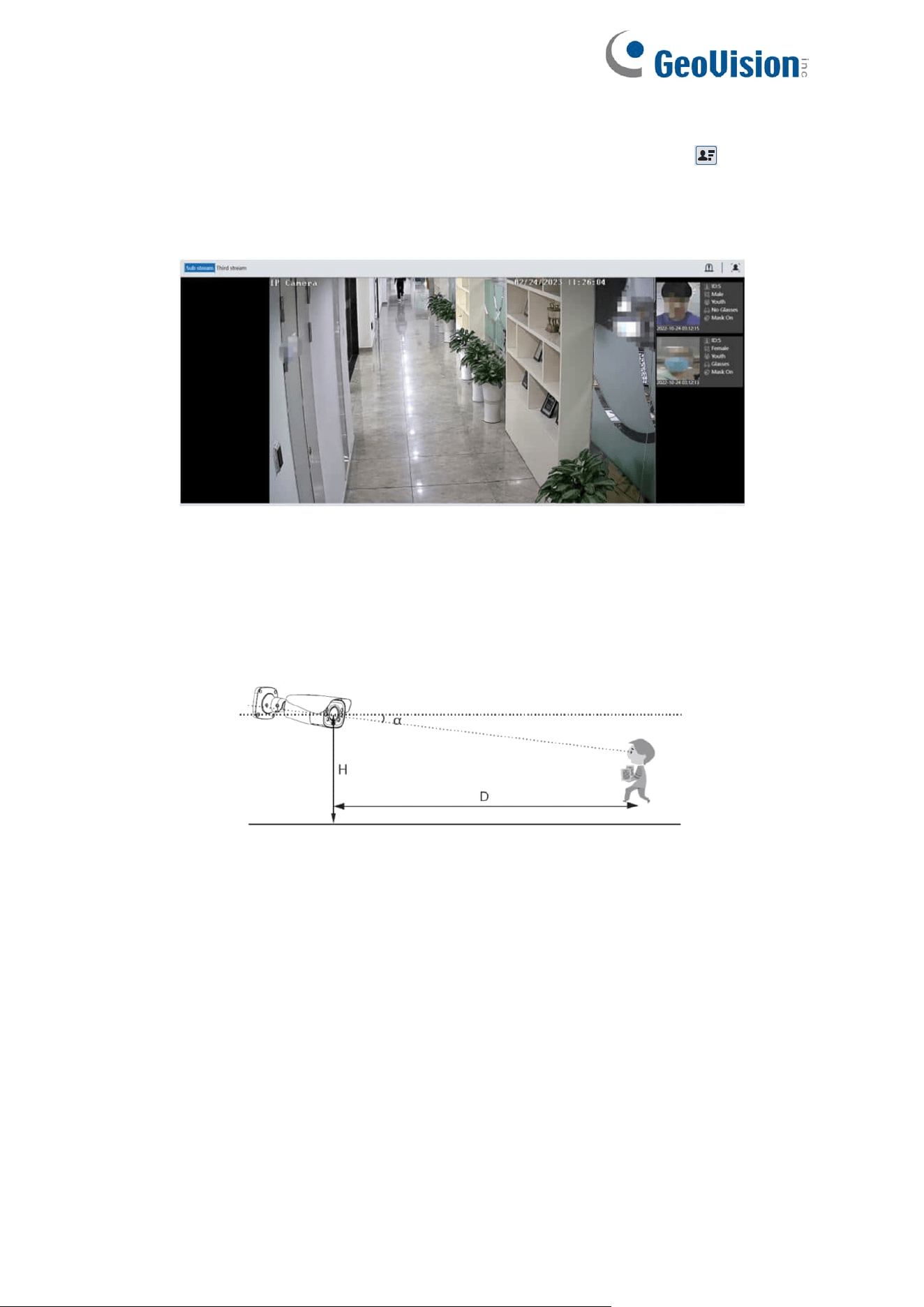
81
Face Capture View
After enabling face detection function, return to the live view interface. Click to go to the
following interface. When there are faces detected, the face pictures will be listed on the right.
The features of captured faces also can be displayed, such as gender, whether to wear a
mask, whether to wear glasses, age group, etc.
※ Configuration requirements of camera and surrounding area
1. Cameras must be installed in the area with stable and adequate light sources.
2. The installation height ranges from 2.0 m to 3.5 m, adjustable according to the
focal-length of different lenses and object distances.
3. The depression angle of the camera shall be less than or equal to 15°.
4. The object distance depends on the focal-length of the lens mounted in the camera.
5. In order to guarantee the captured face recognition rate, the requirement for face capture
area: left or right turn angle is less than about 30°; pitching angle is less than 20°.
6. Face illumination must be uniform, if the brightness is low or there is a large area of
shadow, need to do the light filling.
7. When the capture scenario is backlight, the camera’s BLC/HLC/WDR need to be turned
on, or fill the light.
8. The following scenes are not applicable, like crowded scenes (airport, railway station,
square, etc.), backlight scenes, crossroads and so on.
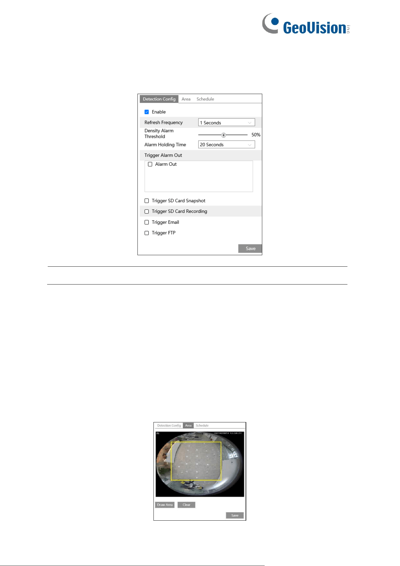
82
4.4.10 Crowd Density
This function can detect the density of the people in a specified area (like square,
supermarket). Go to Config→Event→Crowd Density as shown below.
Note: The Crowd Density function is only applicable to GV-GFER6900.
1. Enable the crowd density detection.
2. Set “Refresh Frequency”, “Density Alarm Threshold” and “Alarm Holding Time”.
Refresh Frequency: The refresh frequency of the detection result.
Density Alarm Threshold: Alarms will be triggered once the percentage of the crowd
density in a specified area exceeds the pre-defined threshold value.
3. Set alarm trigger options. The setup steps are the same as motion detection. Please refer
to motion detection section for details.
4. Set an alarm area for the crowd density detection. Click the “Area” tab as shown below.
Click “Draw Area” and drag the mouse to draw a rectangle area. Drag the border lines of
the rectangle to modify its size and move the rectangle to change its position. Click “Stop
Draw” to stop drawing the area. Click “Clear” to clear the area.
83
5. Set the schedule of the crowd density detection. The setup steps of the schedule are the
same as schedule recording setup (See 4.1.4.2 Schedule Recording Settings).
Note: The camera only can roughly calculate the crowd density through detecting the
human faces. The head or back of the person detected is not counted.
※Configuration of camera and surrounding area
1. The camera lens should face to the people flow.
2. The size range of a single person image should take up from 1% to 5% of the entire
image and the height range of a single person image should occupy from 1/5 to 1/2 of
the entire image.
3. This function is inapplicable to the scene where there are many moving objects except
human shape. (eg. moving cars)
4. A lot of trees and billboards will affect the detection results in the detected area.
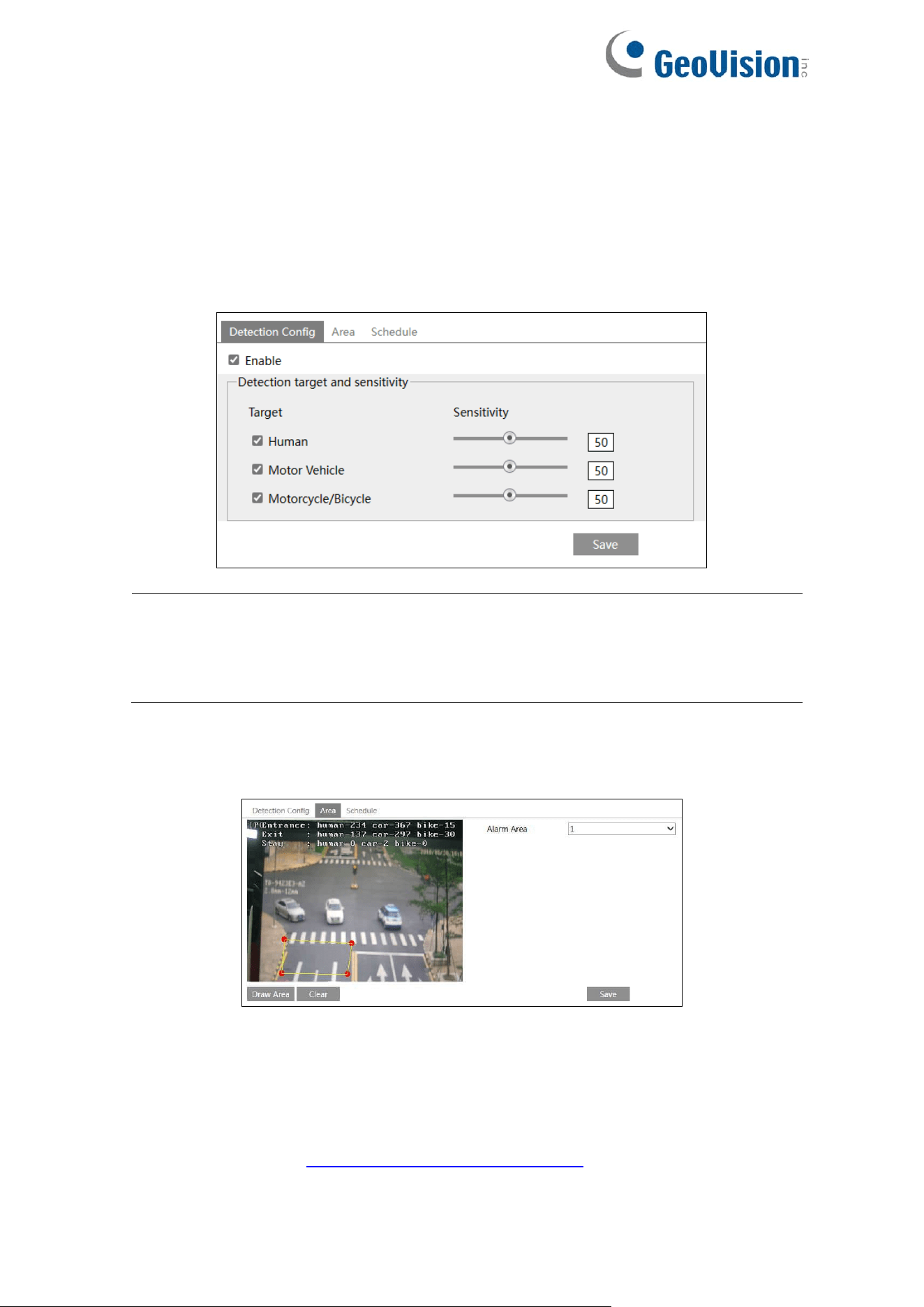
84
4.4.11 Heat Map
Heat Map is to display the flow distribution of people/vehicles in pre-defined areas by different
colors.
For GV-GEBF4911 / GFER6900
1. Enable Heat Map, set snapshot type and detection target type as needed.
Note: For GV-GFER6900:
1. The Motor Vehicle and Motorcycle/Bicycle targets are not applicable.
2. The Heat Map function is only available when the installation method is set to
“Ceiling”.
2. Set heat map display area. Up to 4 areas can be set.
Click the “Draw Area” button and then click around the area where you want to set as the
alarm area in the image on the left side (the alarm area should be a closed area). Click
the “Stop Draw” button to stop drawing. Click the “Clear” button to delete the alarm area.
Click the “Save” button to save the settings.
3. Set the schedule of heat map. The setup steps of the schedule are the same as schedule
recording setup (See 4.1.4.2 Schedule Recording Settings).
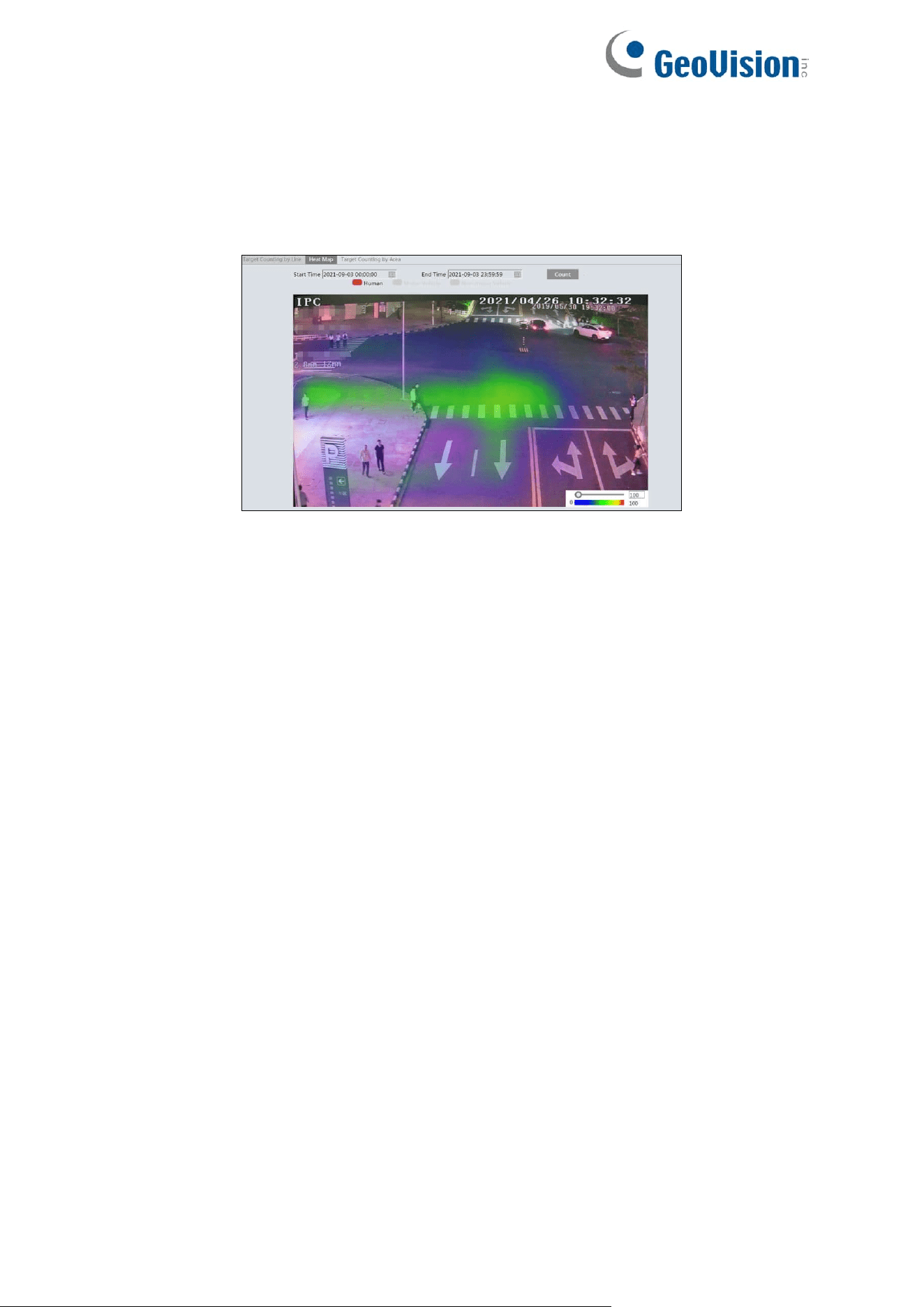
85
4. View the heat map data (click Statistics→Heat Map). Set the start time and the end time.
Click “Count” to view the heat map as shown below. The default heat map is people flow
data display. Click “Motor Vehicle” or “Non-motor Vehicle” to view the corresponding data.
(People flow data is the only display option for GV-GFER6900.)
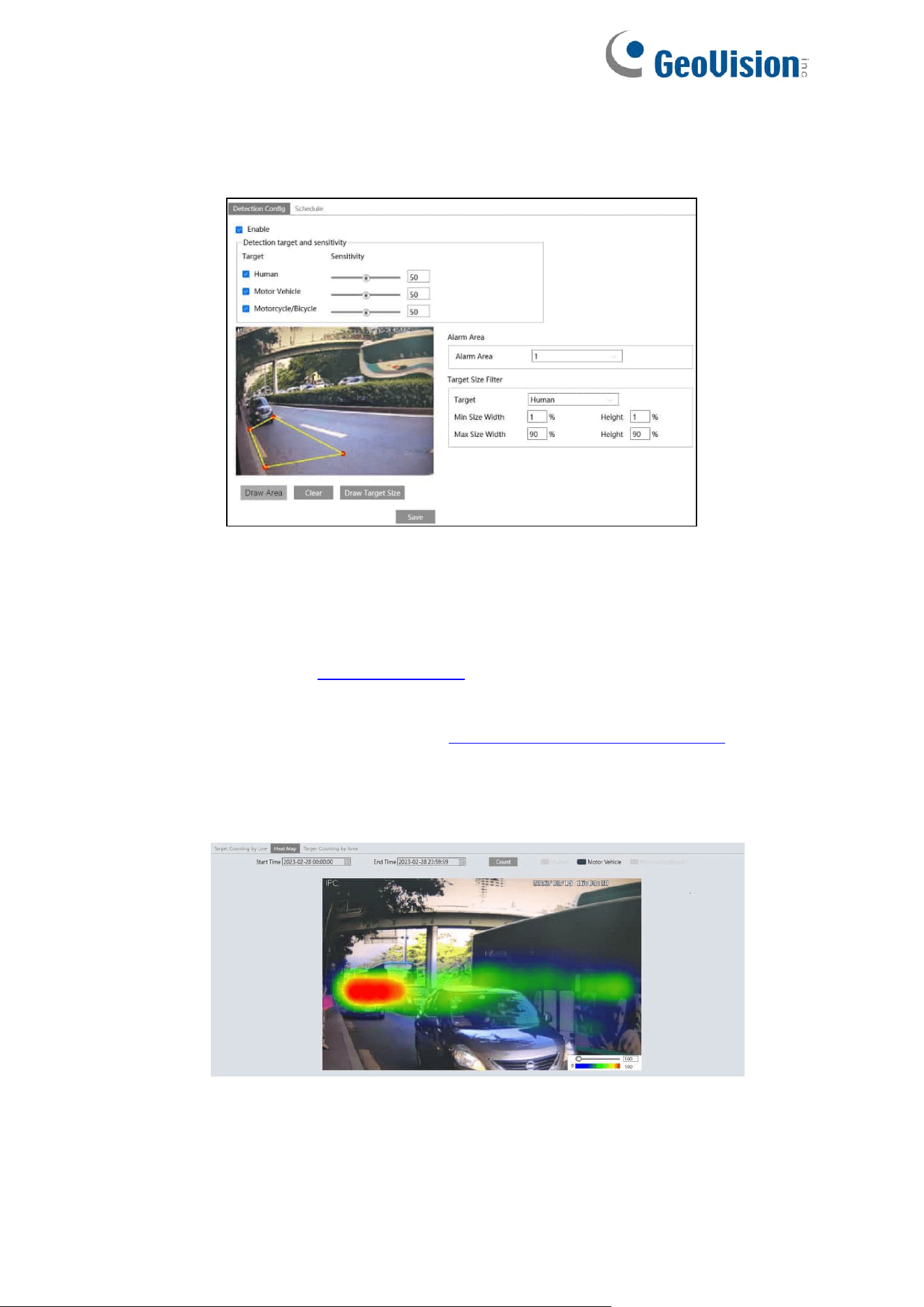
86
For GV-GBL4900 / GBL4911 / GDR4900 / GEB4900 / GVD4910
1. Enable Heat Map, set snapshot type and detection target type as needed.
2. Set heat map display area and target size filter. Up to 4 areas can be set.
Click the “Draw Area” button and then click around the area where you want to set as the
alarm area in the image (the alarm area should be a closed area). Click the “Clear” button to
delete the alarm area. Click the “Save” button to save the settings.
Target size filter setup: The setup steps of the target size filter are the same as line crossing
target size filter setup (See 4.4.3 Line Crossing for details).
3. Set the schedule of region intrusion detection. The setup steps of the schedule are the
same as schedule recording setup (See 4.1.4.2 Schedule Recording Settings).
4. View the heat map data (click Chart→Heat Map). Set the start time and the end time.
Click “Count” to view the heat map as shown below. The default heat map is people flow
data display. Click “Motor Vehicle” or “Motorcycle/bicycle” to view the corresponding data.
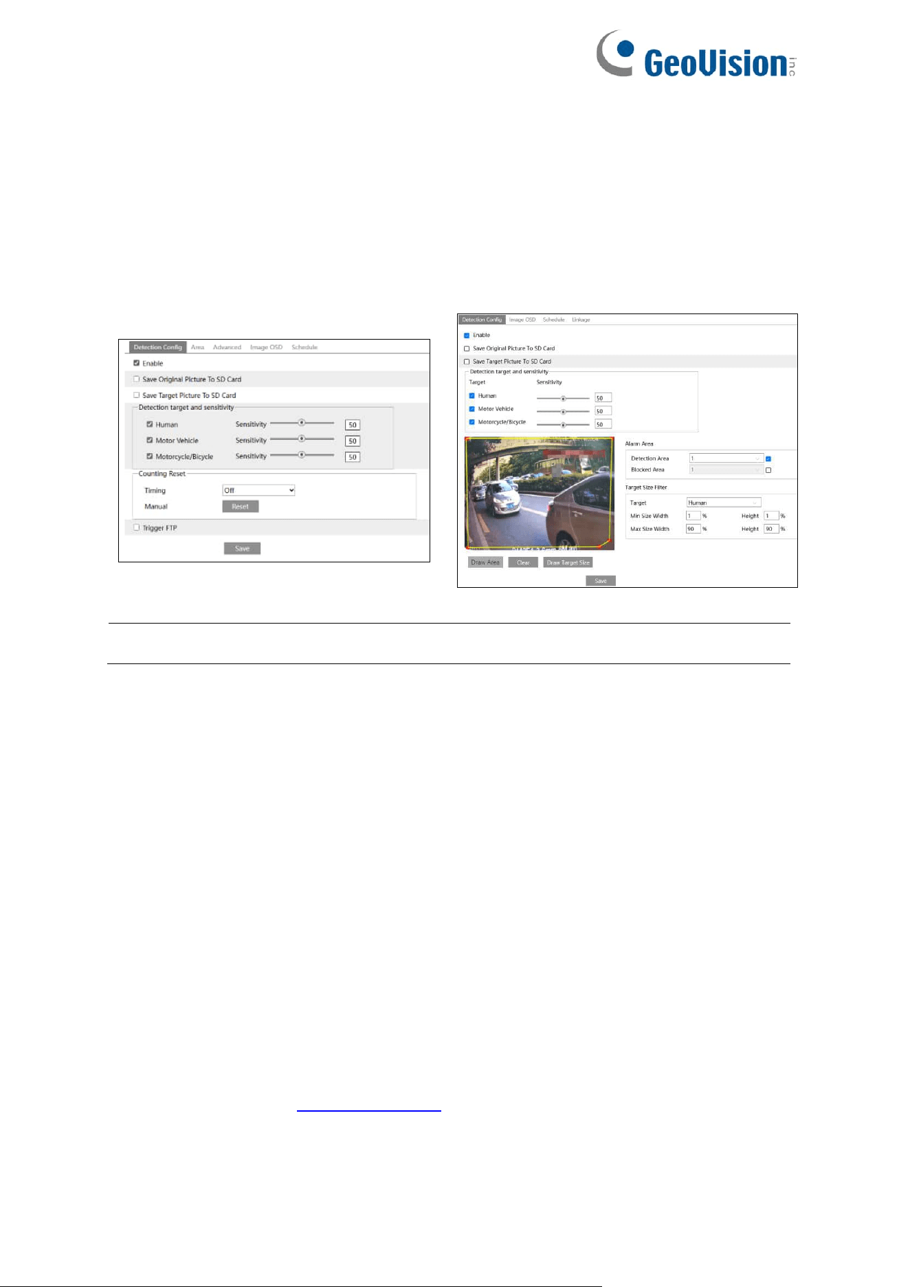
87
4.4.12 Video Metadata
Video Metadata: Human, motor vehicle and non-motor vehicle in the video can be classified,
counted and captured, and the relevant features can be extracted and displayed on the live
interface.
Go to Config→Event→Video Metadata interface. The setting steps are as follows:
GV-GEBF4911
GV-GBL4900 / GBL4911 / GDR4900 /
GEB4900 / GVD4910
Note: The Video Metadata function is not applicable to GV-GFER6900.
1. Enable video metadata and select the snapshot type and the detection target.
Save Original Picture to SD Card: If it is enabled, the detected original pictures will be
captured and saved to the SD card when the targets enter the pre-defined areas.
Save Target Picture to SD Card: If it is enabled, the detected target cutout pictures will
be captured and saved to the SD card when the targets enter the pre-defined areas.
Detection target: Human, motor vehicle and motorcycle/bicycle. All of the three types of
objects can be selected simultaneously.
Counting Reset: The current number of the target counting can be reset. You can
choose to reset the counting daily, weekly or monthly. Click “Reset” to manually reset the
current number of crossing line people/car/bike counting.
Blocked Area: Up to 4 blocked areas can be set. Targets that enter the pre-defined
blocked area will not be captured.
You need to set the detection area and blocked area separately.
Target size filter setup (for GV-GBL4900 / GBL4911 / GDR4900 / GEB4900 /
GVD4910): The setup steps of the target size filter are the same as line crossing target
size filter setup (See 4.4.3 Line Crossing for details).
2. Check “Trigger FTP” as needed. For GV-GBL4900 / GBL4911 / GDR4900 / GEB4900 /
GVD4910, click “Linkage” to access the interface.
3. Set the detection area and blocked area.

88
Detection Area: 4 detection areas can be set. Targets that enter in the pre-defined
detection area will be counted and captured.
Blocked Area: 4 blocked areas can be set. Targets that enter in the pre-defined blocked
area will not be counted and captured.
You need to set the detection area and blocked area separately.
To set detection area:
Check the checkbox of detection area and select the number and to set the detection
area.
Click the “Draw Area” button and then click around the area where you want to set as the
alarm area in the image on the left side (the alarm area should be a closed area). Click
the “Stop Draw” button to stop drawing. Click the “Clear” button to delete the alarm area.
Click the “Save” button to save the settings.
To set blocked area:
Check the checkbox of blocked area and select the number and to set the blocked area.
The setting steps are the same as detection area settings.
Statistics (only for GV-GEBF4911): If enabled, you can see the statistical information of
human, motor vehicle and non-motor vehicle in the live view interface.
The statistical OSD information can be customized as needed.
4. Advanced settings. Click the “Advanced” tab to enter the advanced setting interface.
Select the recognition mode as needed. Interval mode and instant mode can be
selectable.
Interval mode (only for GV-GEBF4911): the system will push the captured picture to the
live interface according to the set interval time.
Instant mode (only for GV-GEBF4911): the system will push the captured picture
immediately once a target is detected.
5. Select the attribute information of the target. Click “Image OSD” and then select the
relevant attribute information. When the target is detected, the information you select will
be displayed in the attribute display area. See Video Metadata View below for details.
6. Set the schedule of video metadata function. The setup steps of the schedule are the
same as schedule recording setup. (See 4.1.4.2 Schedule Recording Settings).
After all settings above are configured, return to the live interface to view the captured pictures
and features.
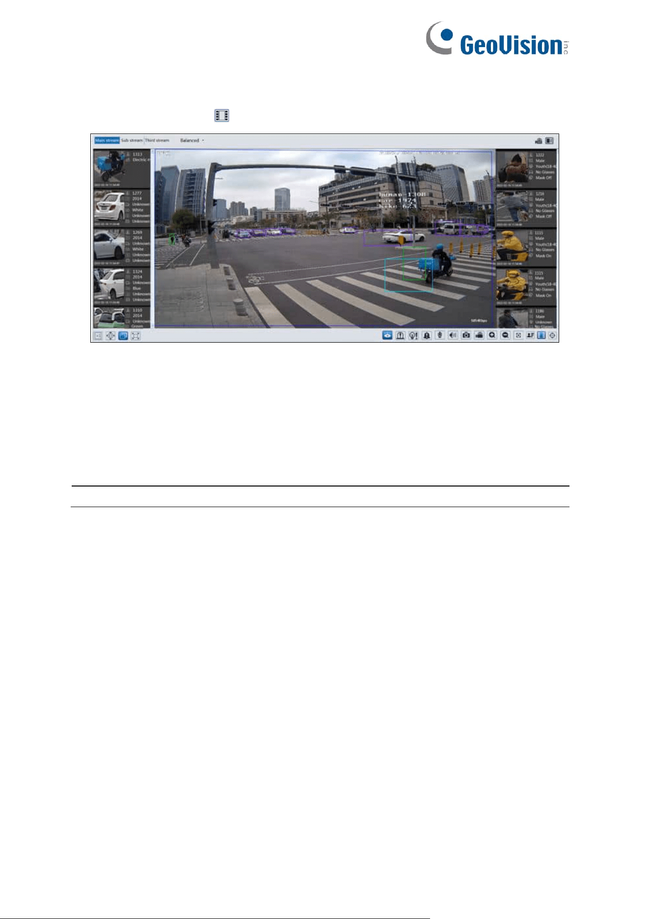
89
Video Metadata View
In the live interface, click to view the following smart snapshots.
Human information will be shown on the right panel.
Motor vehicle and non-motor vehicle information will be shown on the left panel.
Click the captured picture to view the detailed information, including original picture, target
picture and detailed attributes.
A maximum of 1,000 captured pictures can be shown on the live interface. If exceeded, the
previous captured pictures will be overwritten.
Note: This function is not applicable to the scene with a large flow of people and vehicles.
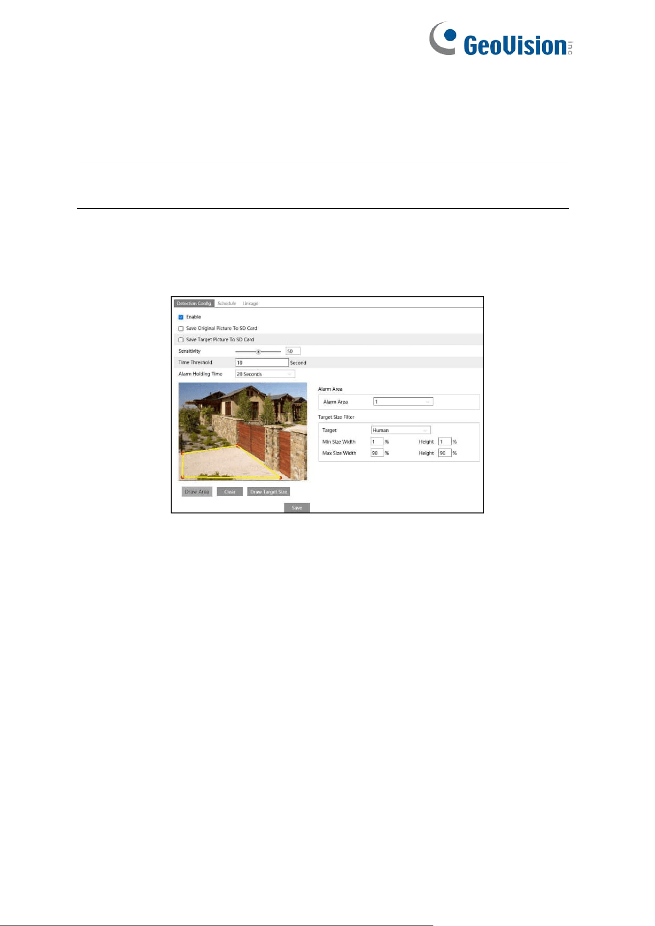
90
s4.4.13 Loitering Detection
Loitering Detection: when someone entering and loitering in a pre-defined area exceeds the
threshold, alarms will be triggered until the object leaves this area.
Note: The Loitering Detection function is only applicable to GV-GBL4900 / GBL4911 /
GDR4900 / GEB4900 / GVD4910.
Go to Event→Loitering Detection interface as shown below. The setting steps are as follows:
1. Enable loitering detection and select the snapshot type.
2. Set sensitivity, time threshold and alarm holding time.
Sensitivity: The higher the value is, the easier the alarm can be triggered.
Time Threshold: the time that a person is allowed to stay in the area. If a person staying
and moving in the specified area exceeds the threshold, alarms will be triggered until this
person leaves or stops moving.
For example: Set the threshold to “60seconds; when a person staying and moving in the
specified area exceeds 60seconds, an alarm is triggered and continues. 2 minutes later,
this person stops moving in the specified area, and then the alarm stops. However, the
alarm will continue once this person moves again in the specified area unless the person
leaves this area.
Alarm Holding Time: it is the time that the alarm extends for after an alarm ends.
3. Set alarm areas and target size filter.
Select the alarm area number. Four alarm areas can be added.
Click the “Draw Area” button and then click around the area where you want to set as the
alarm area in the image (the alarm area should be a closed area). Click the “Clear” button
to delete the alarm area. Click the “Save” button to save the settings.

91
Target size filter setup: The setup steps of the target size filter are the same as line
crossing target size filter setup (See 4.4.3 Line Crossing for details).
4. Set the schedule of the target counting by line. The setup steps of schedule are the same
as the motion detection schedule settings (See 4.1.4.2 Schedule Recording Settings).
5. Click “Linkage” to configure the alarm linkage items. The setup steps are the same as
motion detection. Please refer to 4.3.1 Motion Detection for details.
※ Configuration requirements of camera and surrounding area
1. Avoid enabling this function in complex scenes, such as a scene with a large flow of
people and vehicles.
2. The requirements are similar to line crossing detection. Please refer to Configuration
requirements of camera and surrounding area in 4.4.3 Line Crossing for details.
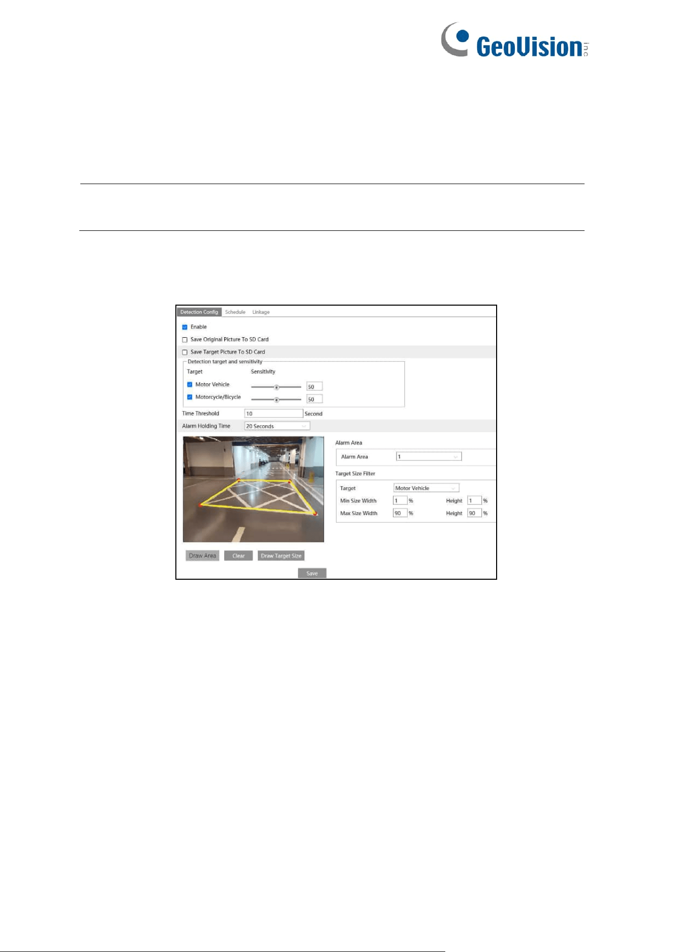
92
4.4.14 Illegal Parking Detection
Illegal Parking Detection: when a vehicle (like a car, truck, motorcycle, etc.) staying in a
no-parking zone exceeds the threshold, alarms will be triggered until the vehicle is driven
away.
Note: The Illegal Parking Detection function is only applicable to GV-GBL4900 /
GBL4911 / GDR4900 / GEB4900 / GVD4910.
Go to Event→Illegal Parking Detection. The setting steps are as follows:
1. Enable illegal parking detection and select the snapshot type.
2. Set the detection target, sensitivity, time threshold and alarm holding time.
Motor Vehicle: a vehicle with four or more wheels
Motorcycle/Bicycle Vehicle: a vehicle with two wheels (e.g., a motorcycle or bicycle)
Sensitivity: the higher the value is, the easier the alarm can be triggered.
Time Threshold: the time that a vehicle is allowed to stay in the specified area. If a
vehicle staying in the area exceeds the threshold, alarms will be triggered until it is driven
away. For example, the time threshold is set to 30s. When the system detects a vehicle
stopping in the set no-parking zone, it will start counting. Alarms will be triggered after it
stays for more than 30s. And the illegal parking alarm will not stop until the vehicle is
driven away from the non-parking zone.
Alarm Holding Time: it is the time that the alarm extends for after the overstaying vehicle
leaves.
3. Set alarm areas and target size filter.
Select the alarm area number. Four alarm areas can be added.

93
Click the “Draw Area” button and then click around the area where you want to set as the
alarm area in the image (the alarm area should be a closed area). Click the “Clear” button
to delete the alarm area. Click the “Save” button to save the settings.
Target size filter setup: The setup steps of the target size filter are the same as line
crossing target size filter setup (See 4.4.3 Line Crossing for details).
4. Set the schedule of the target counting by line. The setup steps of schedule are the same
as the motion detection schedule settings (See 4.1.4.2 Schedule Recording Settings).
5. Click “Linkage” to configure the alarm linkage items. The setup steps are the same as
motion detection. Please refer to 4.3.1 Motion Detection for details.
※ Configuration requirements of camera and surrounding area
1. Avoid enabling this function in complex scenes, such as a scene with a large flow of
people and vehicles.
2. The requirements are similar to line crossing detection. Please refer to Configuration
requirements of camera and surrounding area in 4.4.3 Line Crossing for details.
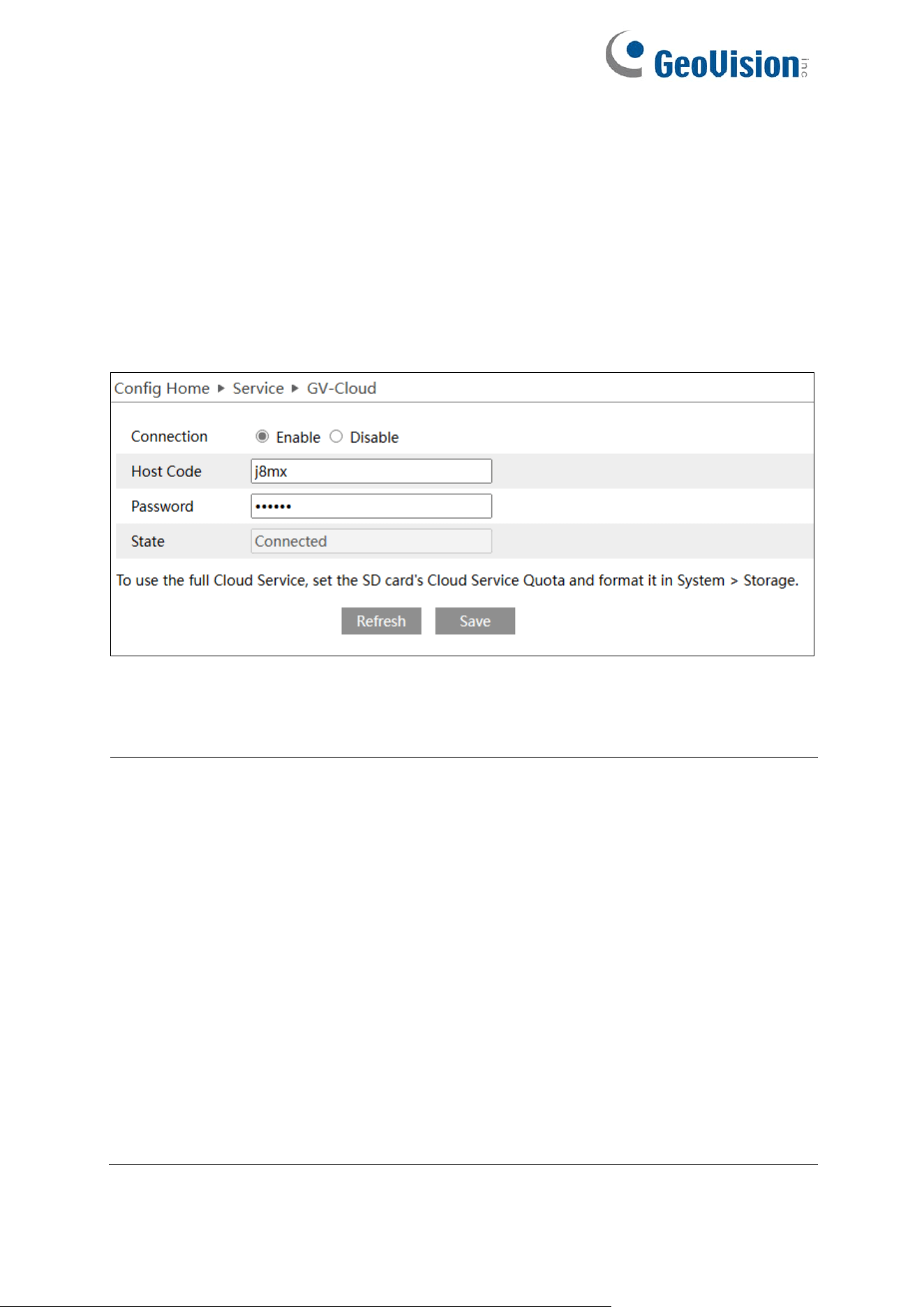
94
4.5 Service
4.5.1 GV-Cloud VMS
The GV-Cloud VMS service is a cloud-based data center and video surveillance solution.
Thousands of on-site videos, alarm devices, and AI events can be monitored and managed
from a single platform. With GV-Cloud VMS, you can easily search for events and watch live
streams or recordings from anywhere using a web browser.
Go to Config→Service→GV-Cloud interface as shown below.
It is required to sign up and log in GV-Cloud first to create a host for the camera.
1. Enable the function and fill in the Host Code and Password created on GV-Cloud.
2. Click Save and Refresh to set up and refresh the connection.
Note:
1. See 7. Connecting to GV-Cloud VMS in the Quick Start Guide for detailed steps.
2. Motion Detection is required for GV-Cloud connection. The event is enabled by default
for the following scenarios:
i. When the camera is successfully connected to GV-Cloud
ii. When the camera reconnects to GV-Cloud after disconnection
iii. When the camera is rebooted after connecting to GV-Cloud
3. Make sure to assign adequate service quota from the camera’s SD card for the
snapshots and recordings uploaded onto GV-Cloud VMS. For details on setting the SD
card storage quota for GV-Cloud VMS, see 4.1.4 Storage.
4. The following events are supported on GV-Cloud VMS:
A. GV-GBL4900 / GBL4911 / GDR4900 / GEBF4911 / GFER6900 / GVD4910: Motion
Detection, Line Crossing, Region Entrance, Region Exiting, Region Intrusion,
Video Exception (Scene Change / Video Blur Detection), I/O events
B. GV-GEB4900: Motion Detection, Line Crossing, Region Entrance, Region Exiting,
Region Intrusion, Video Exception (Scene Change / Video Blur Detection)
5. When connecting to GV-Cloud VMS, avoid connecting to other GV-Software at the
same time.
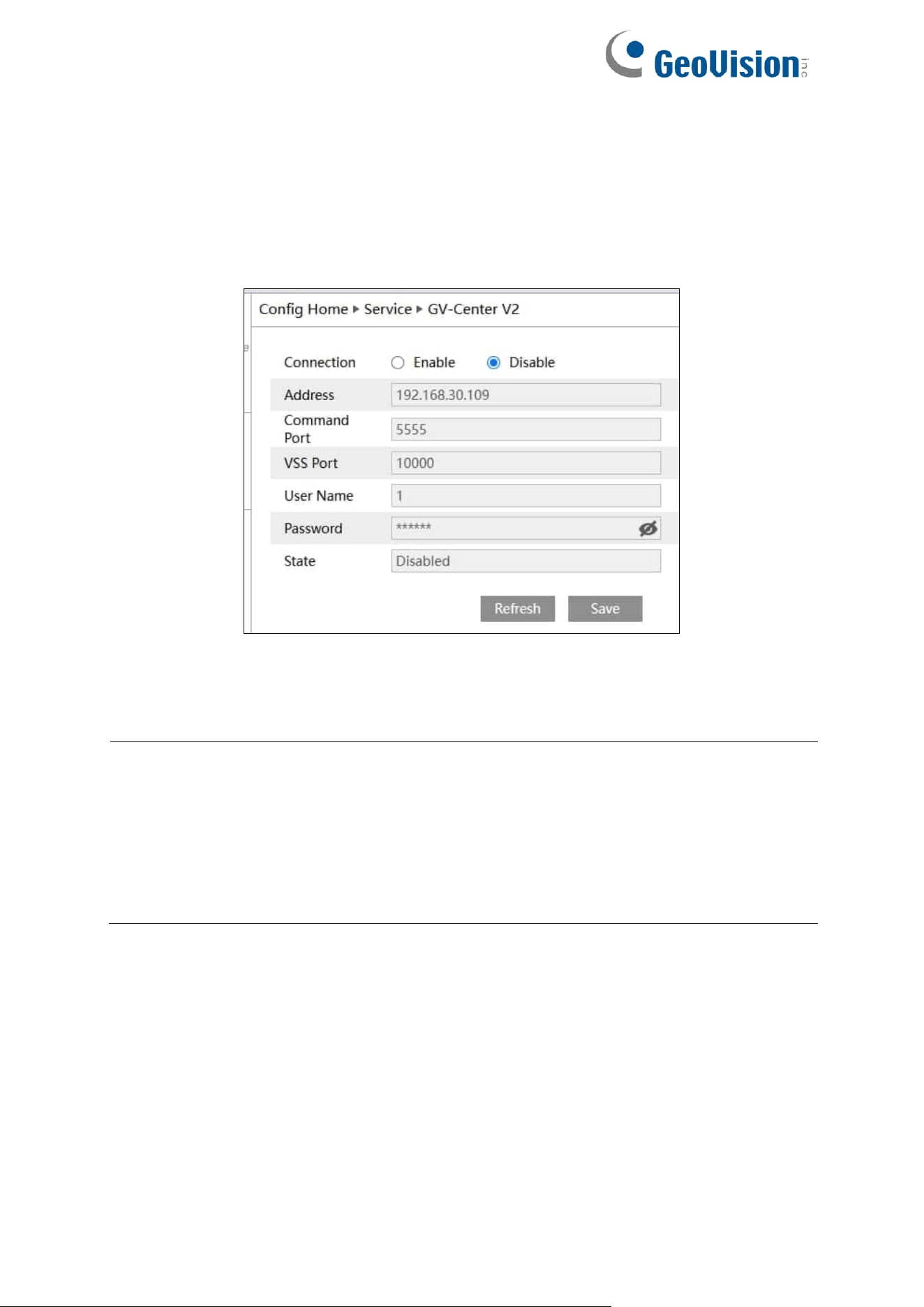
95
4.5.2 GV-Center V2
GV-Center V2 is a Central Monitoring System (CMS) software that allows users to monitor,
receive and record events from IP cameras and surveillance systems on a single platform.
During alert events, GV-Center V2 receives live view and messages with attached recordings,
allowing users to track any abnormalities on the premises.
Go to Config→Service→GV-Center V2 interface as shown below.
1. Enable the function and fill in the connection information.
2. Click Save and Refresh to set up and refresh the connection.
Note:
1. See 8. Connecting to GV-Center V2 in the Quick Start Guide for detailed steps.
2. The following events are supported on GV-Center V2:
A. GV-GBL4900 / GBL4911 / GDR4900 / GEBF4911 / GFER6900 / GVD4910: Motion
Detection, Line Crossing, Region Entrance, Region Exiting, Region Intrusion,
Video Exception (Scene Change Detection), I/O events
B. GV-GEB4900: Motion Detection, Line Crossing, Region Entrance, Region Exiting,
Region Intrusion, Video Exception (Scene Change Detection)
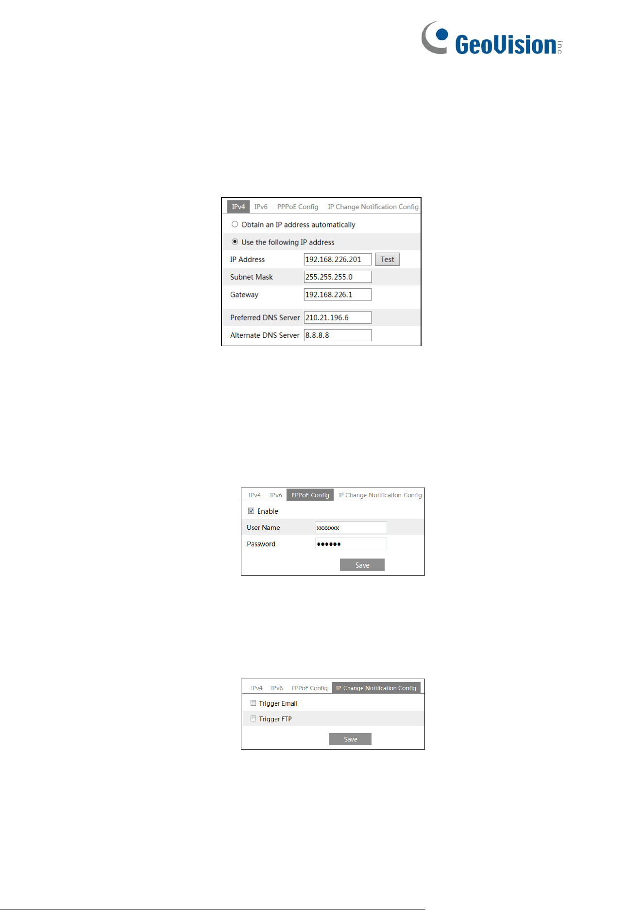
96
4.6 Network Configuration
4.6.1 TCP/IP
Go to Config→Network→TCP/IP interface as shown below. There are two ways for network
connection.
Use IP address (take IPv4 for example): There are two options for IP setup: obtain an IP
address automatically by DHCP and use the following IP address. Please choose one of the
options as needed.
Test: Test the effectiveness of the IP address by clicking this button.
Use PPPoE: Click the “PPPoE Config” tab to go to the interface as shown below. Enable
PPPoE and then enter the user name and password from your ISP.
Either method of network connection can be used. If PPPoE is used to connect internet, the
camera will get a dynamic WAN IP address. This IP address will change frequently. To be
notified, the IP change notification function can be used.
Click “IP Change Notification Config” to go to the interface as shown below.
Trigger Email: When the IP address of the device is changed, the new IP address will be sent
to the email address that has been set up.
Trigger FTP: When the IP address of the device is changed, the new IP address will be sent
to FTP server that has been set up.
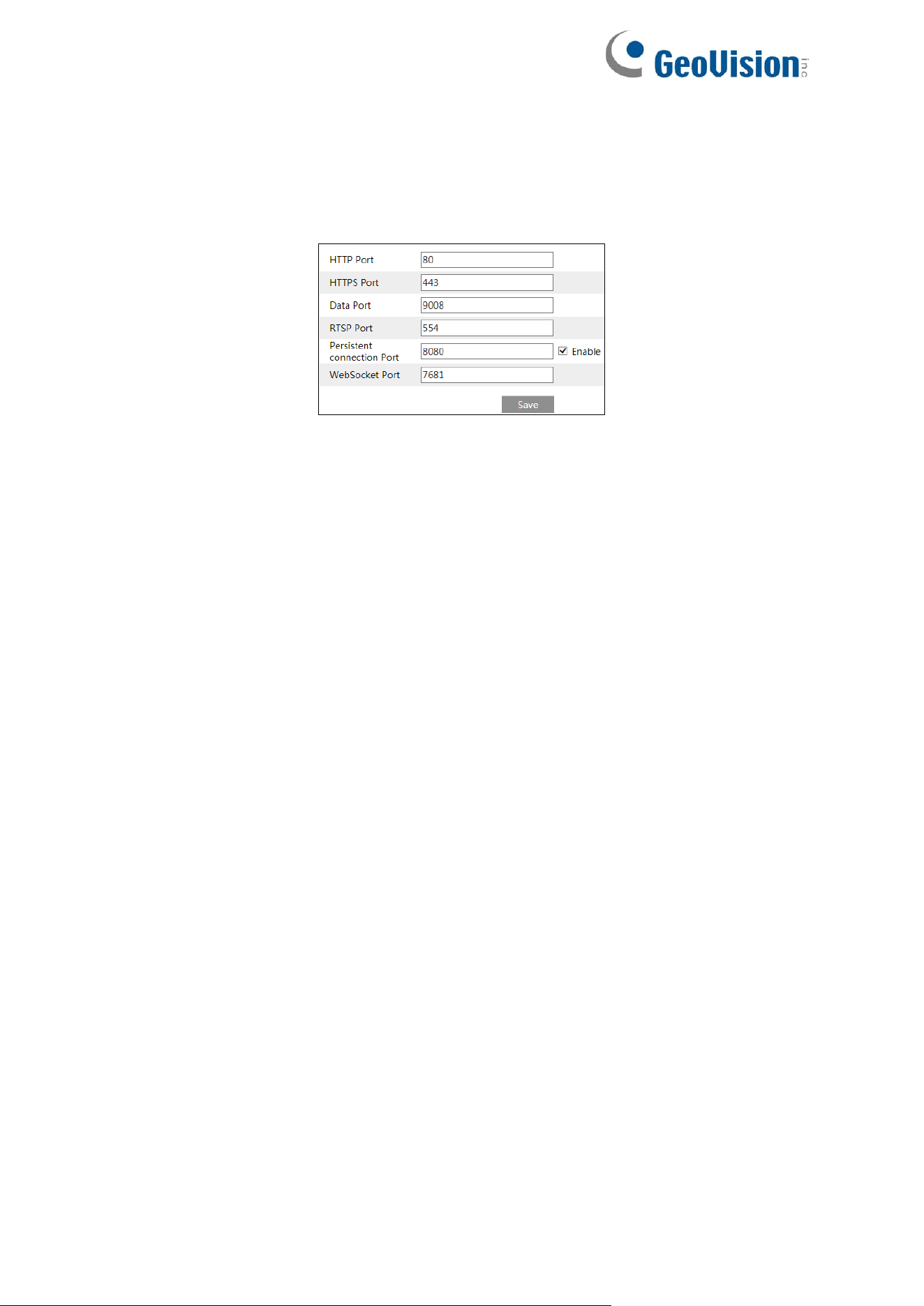
97
4.6.2 Port
Go to Config→Network→Port interface as shown below. HTTP port, Data port and RTSP port
can be set.
HTTP Port: The default HTTP port is 80. It can be changed to any port which is not occupied.
HTTPS Port: The default HTTPs port is 443. It can be changed to any port which is not
occupied.
Data Port: The default data port is 9008. Please change it as necessary.
RTSP Port: The default port is 554. Please change it as necessary.
Persistent Connection Port: The port is used for a persistent connection of the third-party
platform to push smart data, like face pictures.
WebSocket Port: Communication protocol port for the plug-in free preview.
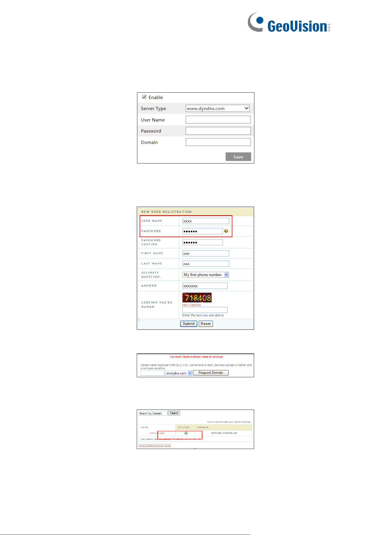
98
4.6.3 DDNS
If the camera is set up with a DHCP connection, DDNS should be set for the internet.
1. Go to Config→Network→ DDNS.
2. Apply for a domain name. Take www.dvrdyndns.com for example.
Enter www.dvrdydns.com in the address bar of a browser to visit its website. Then, click
the “Registration” button.
Create domain name.
After the domain name is successfully applied for, the domain name will be listed as
below.
3. Click “Edit” and “Enable” (for GV-GDR4900 / GEB4900 / GFER6900). Enter the
username, password, domain you apply for in the DDNS configuration interface.
4. Click the “Save” button to save the settings.
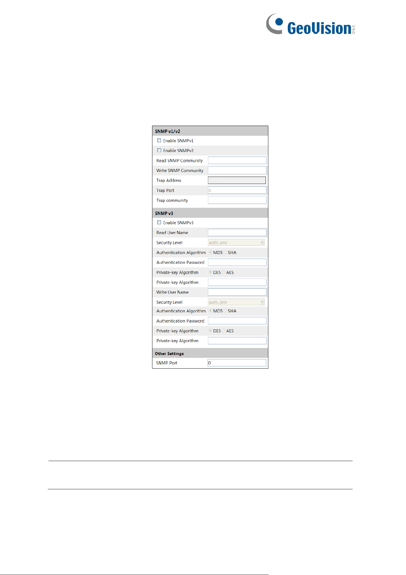
99
4.6.4 SNMP
To get camera status, parameters and alarm information and remotely manage the camera,
the SNMP function can be used. Before using SNMP, please install an SNMP management
tool and set the parameters of the SNMP, such as SNMP port, trap address.
1. Go to Config→Network→SNMP.
2. Click “Edit” at the bottom (for GV-GBL4900 / GBL4911 / GDR4900 / GEB4900 /
GFER6900 / GVD4910). Check the corresponding version checkbox (Enable SNMPv1,
Enable SNMPv2, Enable SNMPv3) according to the version of the SNMP software that
will be used.
3. Set the values for “Read SNMP Community”, “Write SNMP Community”, “Trap Address”,
“Trap Port” and so on. Please make sure the settings are the same as that of the SNMP
software.
Note: Please use the different version in accordance with the security level you required.
The higher the version is, the higher the level of the security is.
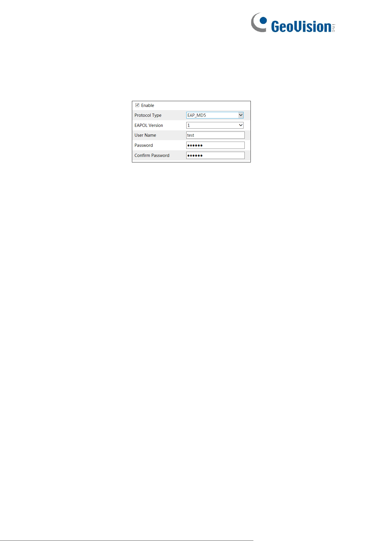
100
4.6.5 802.1x
If it is enabled, the camera’s data can be protected. When the camera is connected to the
network protected by the IEEE 802.1x, user authentication is needed.
To use this function, the camera shall be connected to a switch supporting 802.1x protocol.
The switch can be reckoned as an authentication system to identify the device in a local
network. If the camera connected to the network interface of the switch has passed the
authentication of the switch, it can be accessed via the local network.
For GV-GBL4900 / GBL4911 / GDR4900 / GEB4900 / GFER6900 / GVD4910: Click “Edit” to
start the setup.
Protocol type / EAPOL version: Please use the default settings.
User name / Password: The user name and password must be the same with the user name
and password applied for and registered in the authentication server.
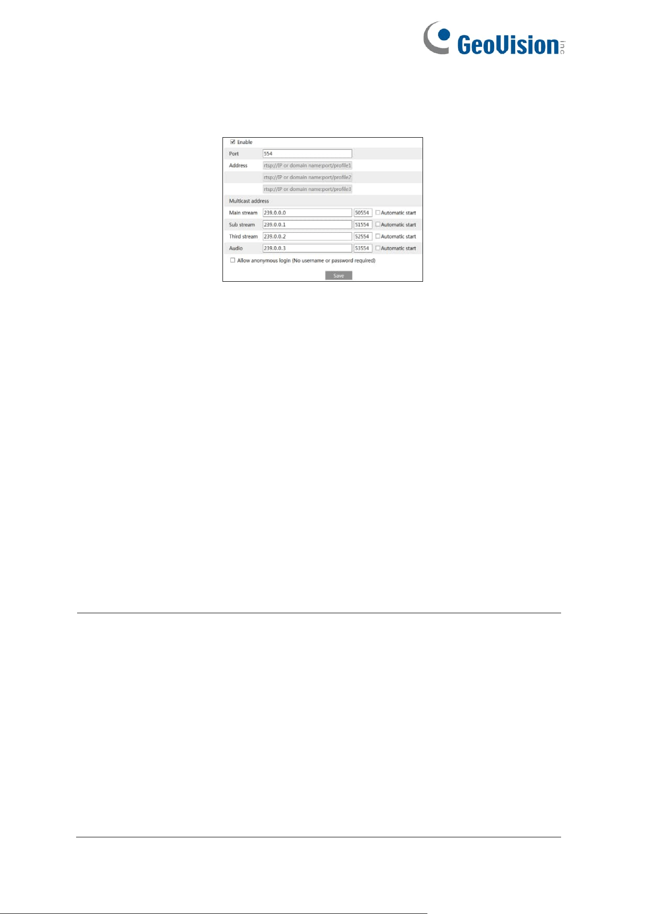
101
4.6.6 RTSP
Go to Config→Network→RTSP.
For GV-GBL4900 / GBL4911 / GDR4900 / GEB4900 / GFER6900 / GVD4910: Click “Edit” to
start the setup. Select “Enable” to enable the RTSP function.
Port: Access port of the streaming media. The default number is 554.
RTSP Address: The RTSP address (unicast) format that can be used to play the stream in a
media player.
Multicast Address
⚫ Main stream: The address format is “rtsp://IP address:rtsp port/profile1?transportmode=mcast”.
⚫ Sub stream: The address format is “rtsp://IP address:rtsp port/profile2?transportmode=mcast”.
⚫ Third stream: The address format is “rtsp://IP address:rtsp port/profile3?transportmode=mcast”.
Audio: Having entered the main/sub stream in a VLC player, the video and audio will play
automatically.
If “Allow anonymous login…” is checked, there is no need to enter the username and
password to view the video.
If “Automatic Start” is enabled, the multicast received data should be added into a VLC player
to play the video.
Note:
1. This camera supports local play through a VLC player. Enter the RTSP address
(unicast or multicast, eg. rtsp://192.168.226.201:554/profile1?transportmode=mcast)
in a VLC player to realize the simultaneous play with the web client.
2. The IP address mentioned above cannot be the address of IPv6.
3. Avoid the use of the same multicast address in the same local network.
4. When playing the video through the multicast streams in a VLC player, please pay
attention to the mode of the VLC player. If it is set to TCP mode, the video cannot be
played.
5. If the coding format of the video of the main stream is MJPEG, the video may be
disordered at some resolutions.
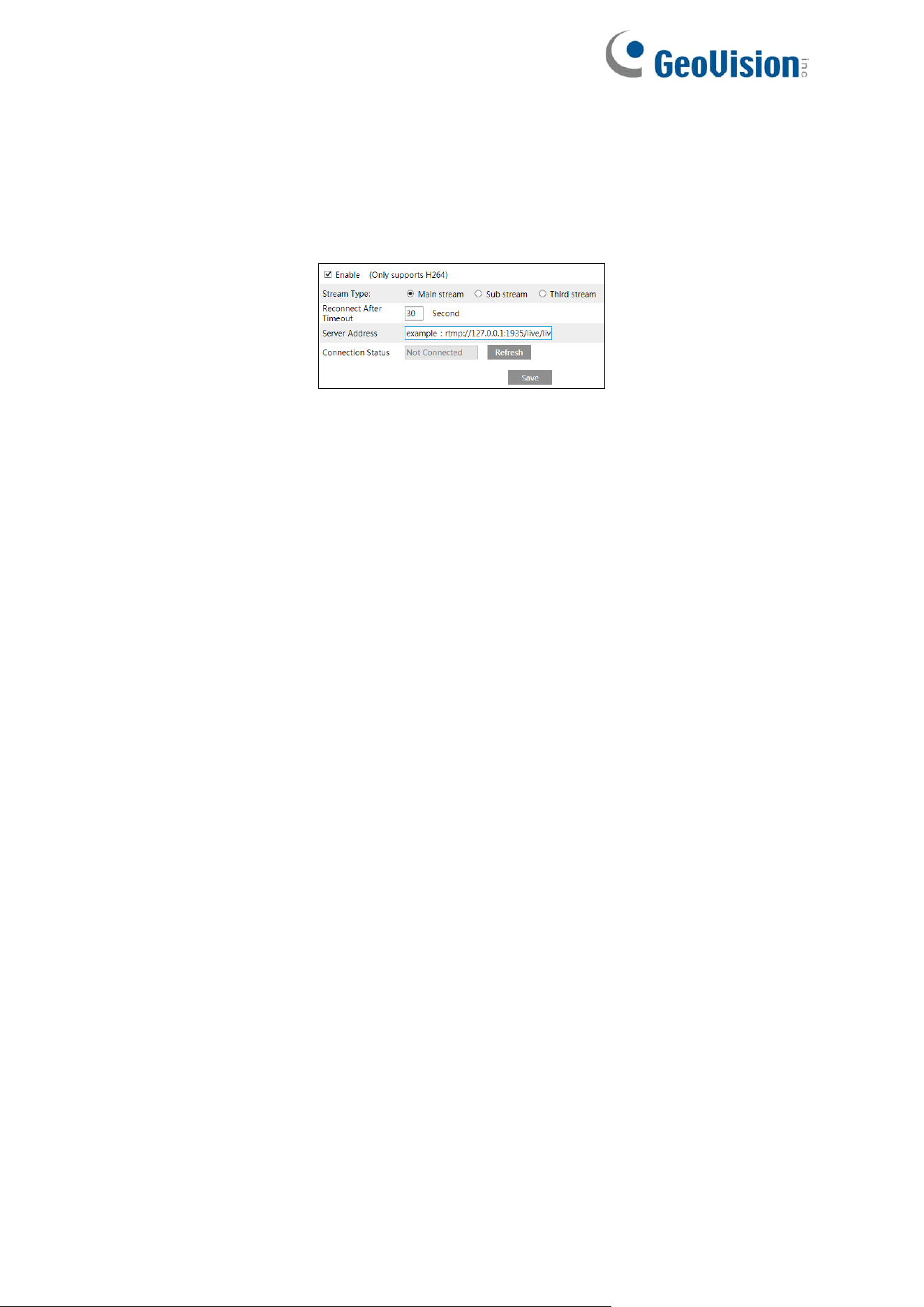
102
4.6.7 RTMP
You can access the third-party (like YouTube) to realize video live view through RTMP
protocol.
Go to Config→Network→RTMP.
For GV-GBL4900 / GBL4911 / GDR4900 / GEB4900 / GFER6900 / GVD4910: Click “Edit” to
start the setup. Check “Enable”, select stream type, set the reconnection time after timeout
and server address as needed.
Server address: Enter the server address allocated by the third-party server.
After that, click “Save” to save the settings. Then click “Refresh” to view the connection status.
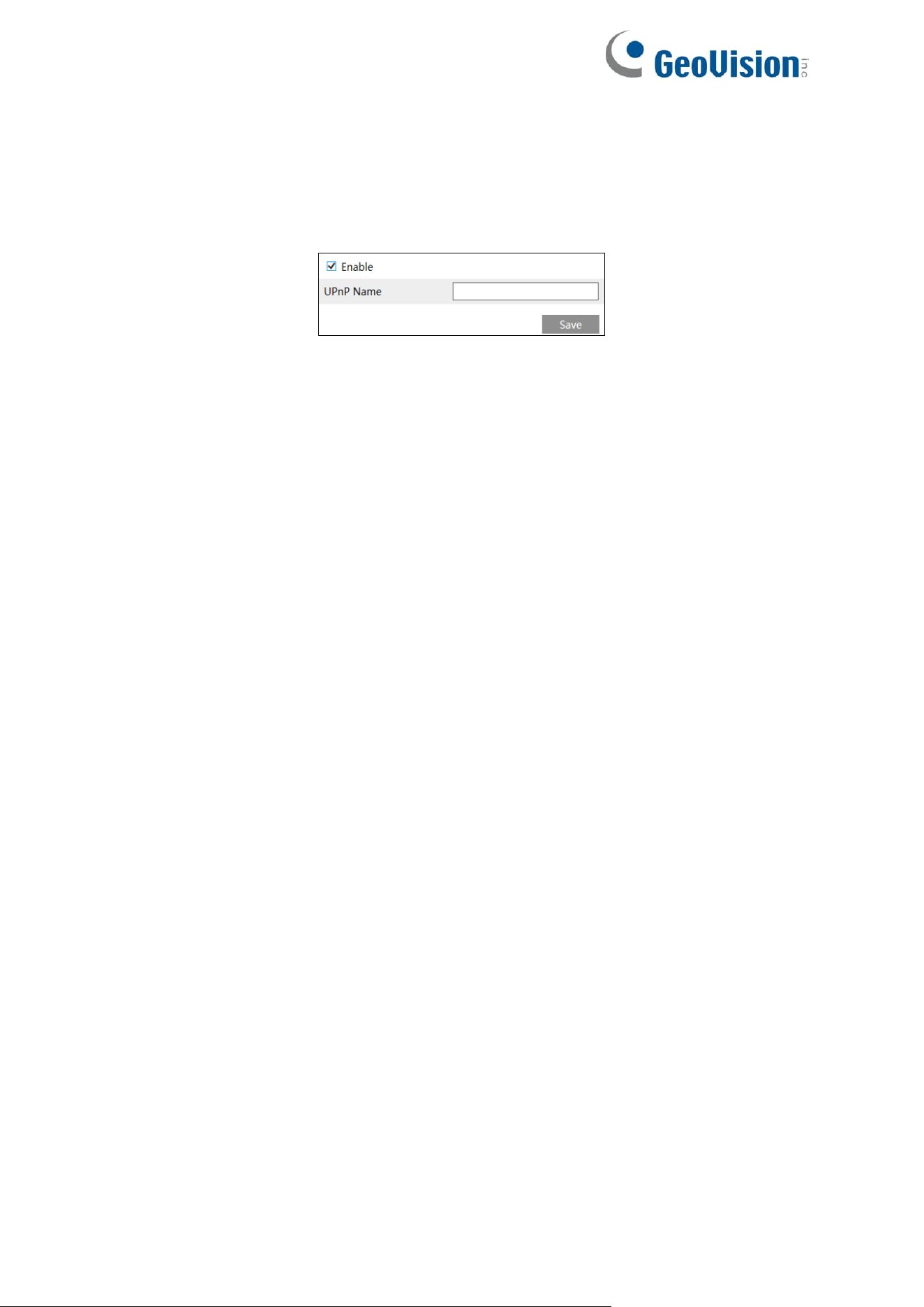
103
4.6.8 UPnP
If this function is enabled, the camera can be quickly accessed through the LAN.
Go to Config→Network→UPnP. Enable UPNP and then enter UPnP name.
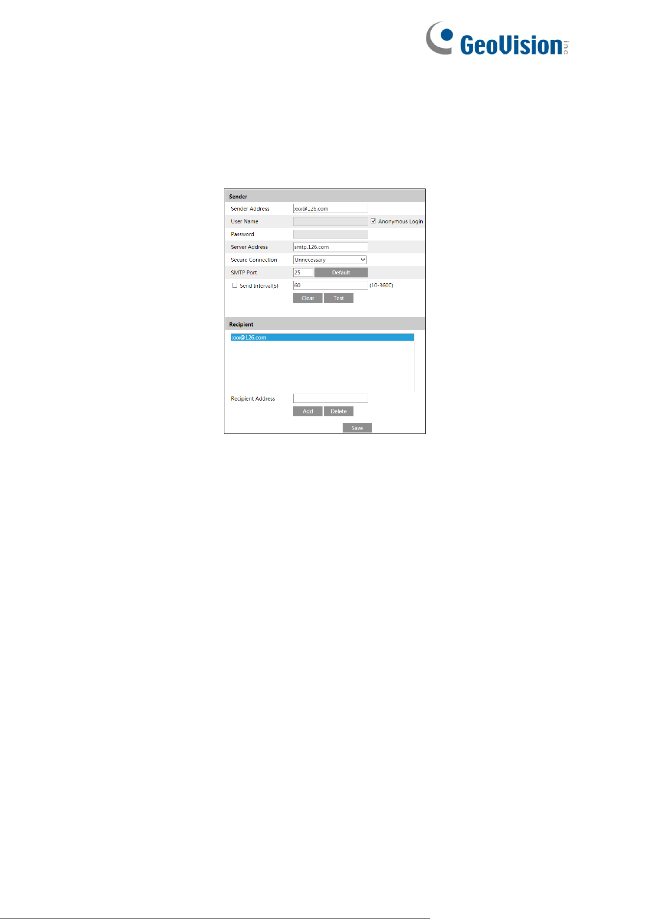
104
4.6.9 Email
If you need to trigger Email when an alarm happens or IP address is changed, please set the
Email here first.
Go to Config→Network →Email.
For GV-GBL4900 / GBL4911 / GDR4900 / GEB4900 / GFER6900 / GVD4911, click “Edit and
Test” to set the sender and the recipient.
Sender Address: Sender’s e-mail address.
User name and password: Sender’s user name and password (you don’t have to enter the
username and password if “Anonymous Login” is enabled).
Server Address: The SMTP IP address or host name.
Select the secure connection type at the “Secure Connection” pull-down list according to
what’s required.
SMTP Port: The SMTP port.
Send Interval(S): The time interval of sending email. For example, if it is set to 60 seconds
and multiple motion detection alarms are triggered within 60 seconds, they will be considered
as only one alarm event and only one email will be sent. If one motion alarm event is triggered
and then another motion detection alarm event is triggered after 60 seconds, two emails will
be sent. When different alarms are triggered at the same time, multiple emails will be sent
separately.
Click the “Test” button to test the connection of the account.
Recipient Address: Receiver’s e-mail address.
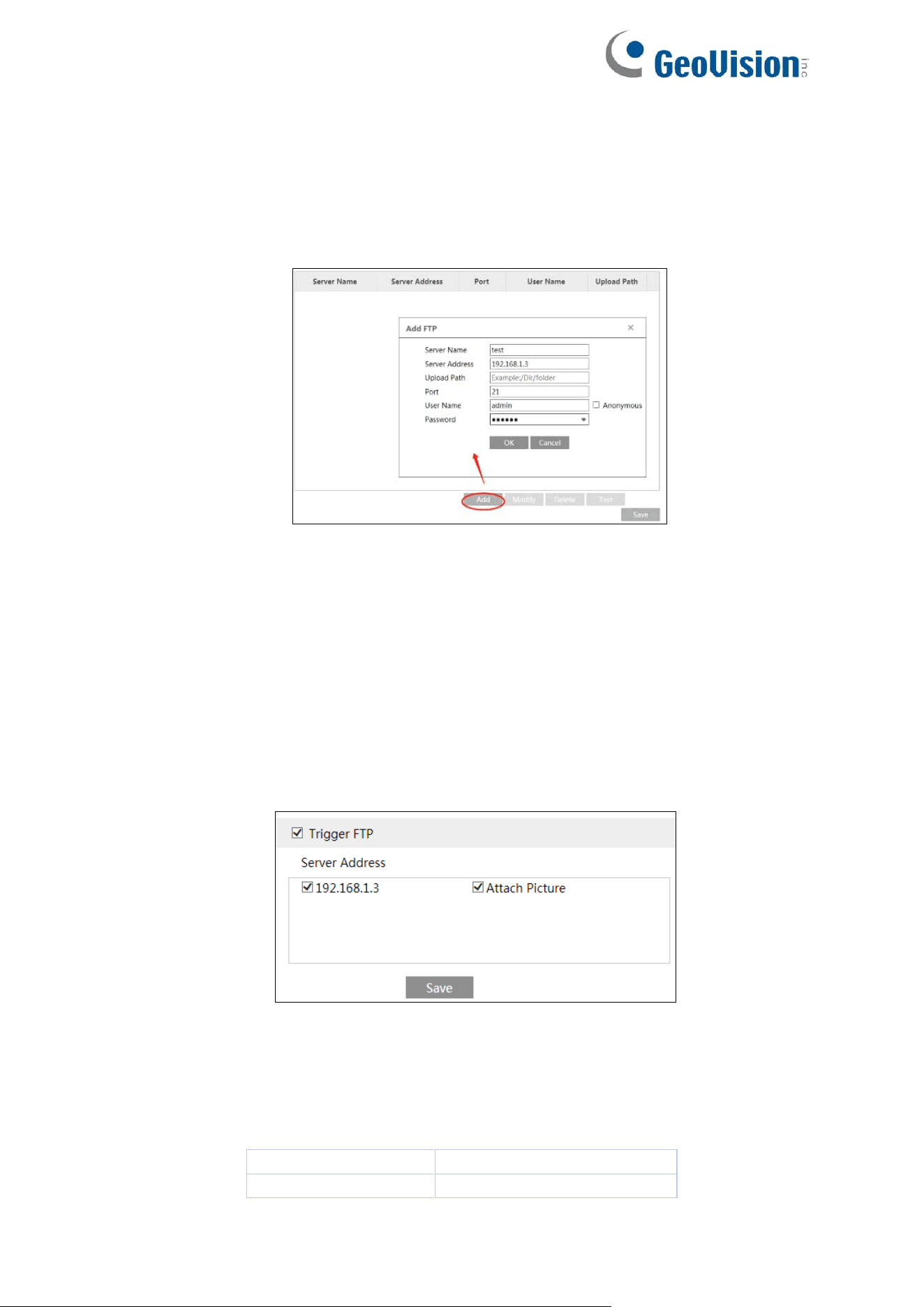
105
4.6.10 FTP
After an FTP server is set up, captured pictures from events will be uploaded to the FTP
server.
1. Go to Config→Network →FTP.
2. For GV-GBL4900 / GBL4911 / GDR4900 / GEB4900 / GFER6900 / GVD4910: Click “Edit
and Test” to start the setup.
3. Click “Add” to add the information of the FTP. After that, click “Save” to save the settings.
Server Name: The name of the FTP server.
Server Address: The IP address or domain name of the FTP.
Upload Path: The directory where files will be uploaded to.
Port: The port of the FTP server.
User Name and Password: The username and password that are used to login to the
FTP server.
4. In the event setting interface (like intrusion, line crossing, etc.), trigger FTP as shown
below.
Rule of FTP storage path: /device MAC address/event type/date/time/
For example: a face detection alarm occurs
FTP file path: \00-18-ae-a8-da-2a\VFD\2021-01-09\14\
Event name table:
File Name
Event Type
IP
IP address change

106
MOTION
Motion Detection
SENSOR
Sensor Alarm
TRIPWIRE
Line Crossing Detection
PERIMETER
Region Intrusion Detection
OSC
Object Abandoned/Missing
AVD
Video Exception
VFD
Face Detection
AOIENTRY
Region Entrance
AOILEAVE
Region Exiting
PASSLINECOUNT
Target Counting by Line
TRAFFIC
Target Counting by Area
LOITER
Loitering Detection
PVD
Illegal Parking Detection
SDFULL
SD Full
SDERROR
SD Error
VSD
Video Metadata
TXT file content:
Device name: xxx mac: device MAC address Event Type time:
For example:
device name: IPC mac: 00-18-ae-a8-da-2a MOTION time: 2021-03-16 12:20:07
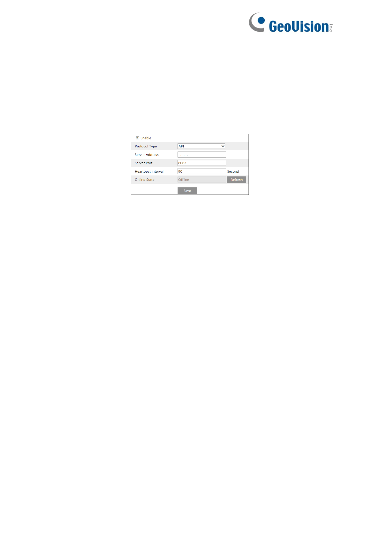
107
4.6.11 HTTP POST
For GV-GBL4900 / GBL4911 / GDR4900 / GEB4900 / GFER6900 / GVD4910: Click “Edit” to
start the setup.
Go to Config→Network →HTTP POST interface.
Check “Enable”, select protocol type and then set the server address (IP address/domain
name), server port and heartbeat interval.
Server Address: The IP address/domain name of the third-party platform.
Server Port: The server port of the third-party platform.
After the above parameters are set, click “Save” to save the settings. Then the camera will
automatically connect the third-party platform. The online state can be viewed in the above
interface. After the camera is successfully connected, it will send the alarm information (HTTP
format) to the third-party platform once the smart alarm is triggered. The alarm information
includes target tracing coordinates, target features, the captured original/target image (like the
captured face picture, motor vehicle picture) and so on.
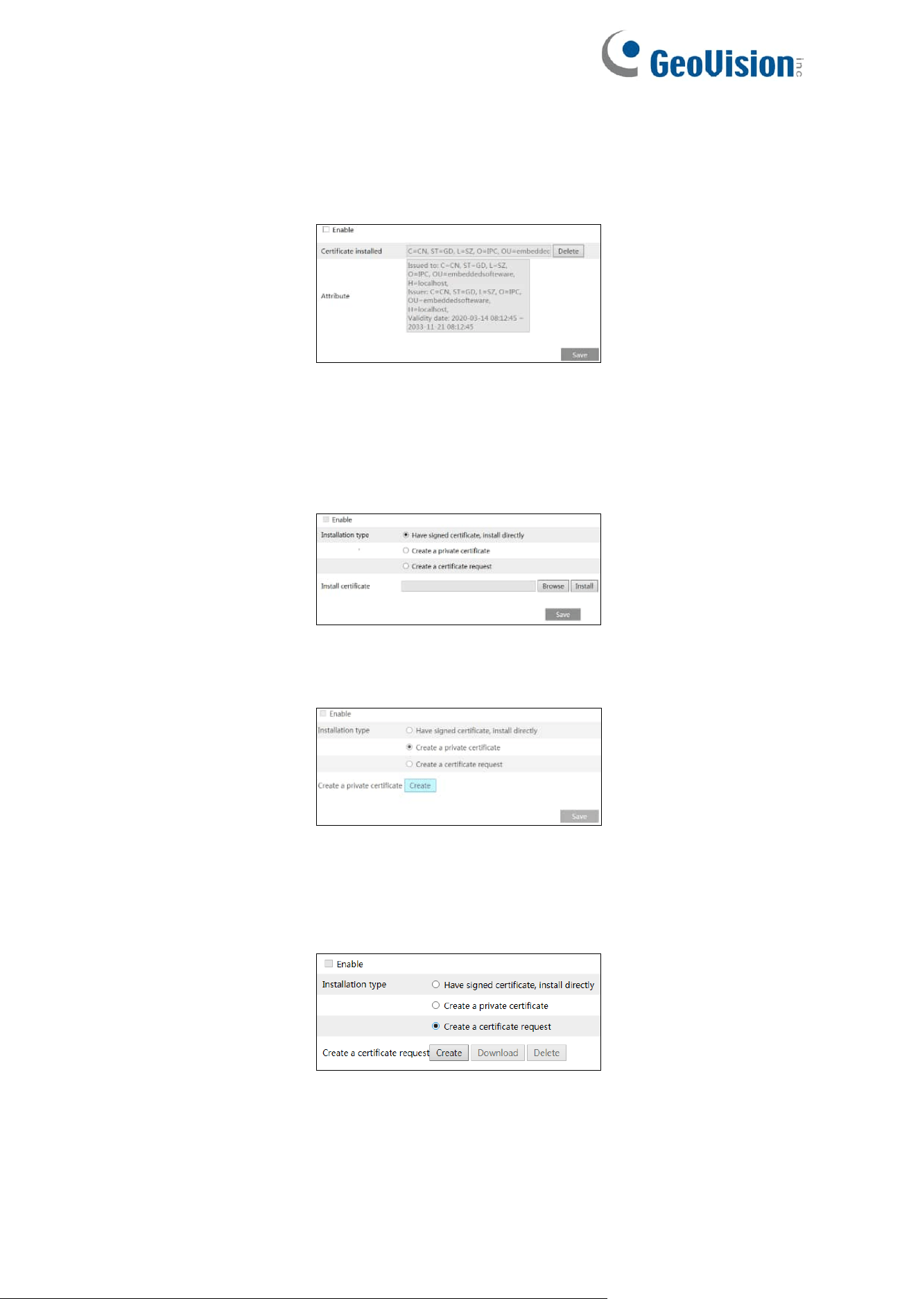
108
4.6.12 HTTPS
HTTPs provides authentication of the web site and protects user privacy.
Go to Config →Network→HTTPS as shown below.
There is a certificate installed by default as shown above. Enable this function and save it.
Then the camera can be accessed by entering https://IP: https port via the web browser (e.g.,
https://192.168.226.201:443).
A private certificate can be created if users don’t want to use the default one. Click “Delete” to
cancel the default certificate. Then the following interface will be displayed.
*If there is a signed certificate, click “Browse” to select it and then click “Install” to install it.
*Click “Create a private certificate” to enter the following creation interface.
Click the “Create” button to create a private certificate. Enter the country (only two letters
available), domain (camera’s IP address/domain), validity date, password, province/state,
region and so on. Then click “OK” to save the settings.
*Click “Create a certificate request” to enter the following interface.
Click “Create” to create the certificate request. Then download the certificate request and
submit it to the trusted certificate authority for signature. After receiving the signed certificate,
import the certificate to the device.
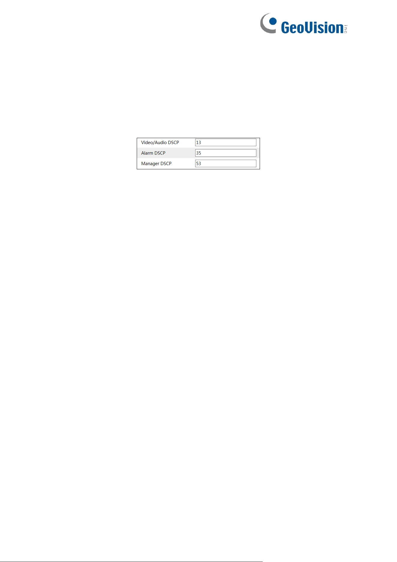
109
4.6.13 QoS
QoS (Quality of Service) function is used to provide different quality of services for different
network applications. With the deficient bandwidth, the router or switch will sort the data
streams and transfer them according to their priority to solve the network delay and network
congestion by using this function.
Go to Config→Network→QoS.
Video/Audio DSCP: The range is from 0 to 63.
Alarm DSCP: The range is from 0 to 63.
Manager DSCP: The range is from 0 to 63.
Generally, the larger the number is, the higher the priority is.
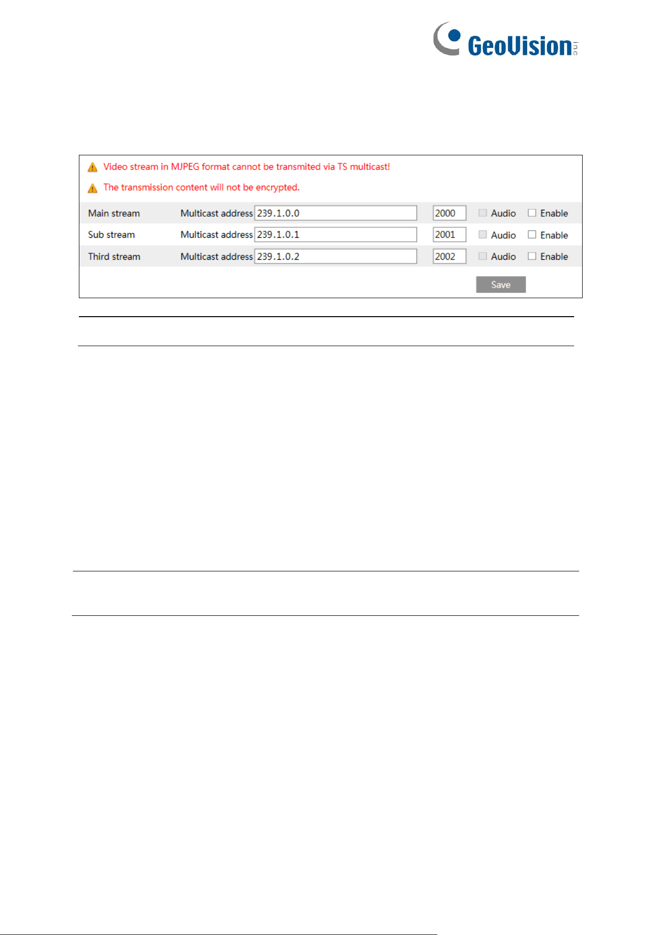
110
4.6.14 TS Multicast
By using transport stream multicast (TS Multicast), multiple users can view the video image
simultaneously even if there is not enough bandwidth.
Note: TS Multicast is only applicable to GV-GEBF4911.
Multicast address: the multicast IP address of Main Stream/Sub Stream/Third Stream ranges
from 224.0.0.0 to 239.255.255.255.
Port: Main stream:2000; sub stream:2001; third stream:2002
Main stream: The address format is “udp://@IP address: main stream port.”
Sub stream: The address format is “udp://@IP address: sub stream port.”
Third stream: The address format is “udp://@IP address: third stream port.”
Audio: if enabled, the video and audio will play automatically.
For example: you can test the TS multicast by using a VLC player. Enter the TS multicast
address (eg. udp://@239.1.0.1:2001) in a VLC player.
Note: The TS multicast user also will be counted as an online user. You can go to
Config→Security→Online User to view.
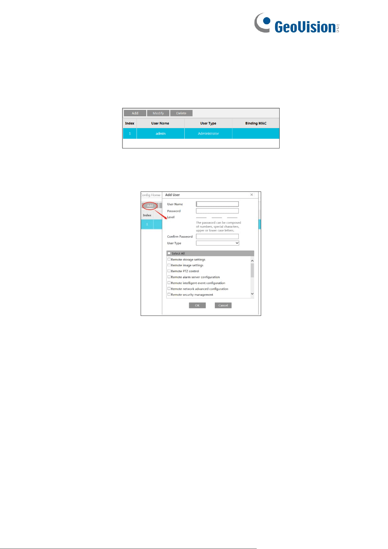
111
4.7 Security Configuration
4.7.1 User Configuration
Go to Config→Security→User interface as shown below.
Add user:
1. Click the “Add” button to pop up the following textbox.
2. Enter user name in the “User Name” textbox.
3. Enter the password in the “Password” and “Confirm Password” textbox. Please set the
password according to the requirement of the password security level (Go to
Config→Security→Security Management→Password Security interface to set the
security level).
4. Choose the user type and select the desired user permissions.
5. Click the “OK” button and then the newly added user will be displayed in the user list.
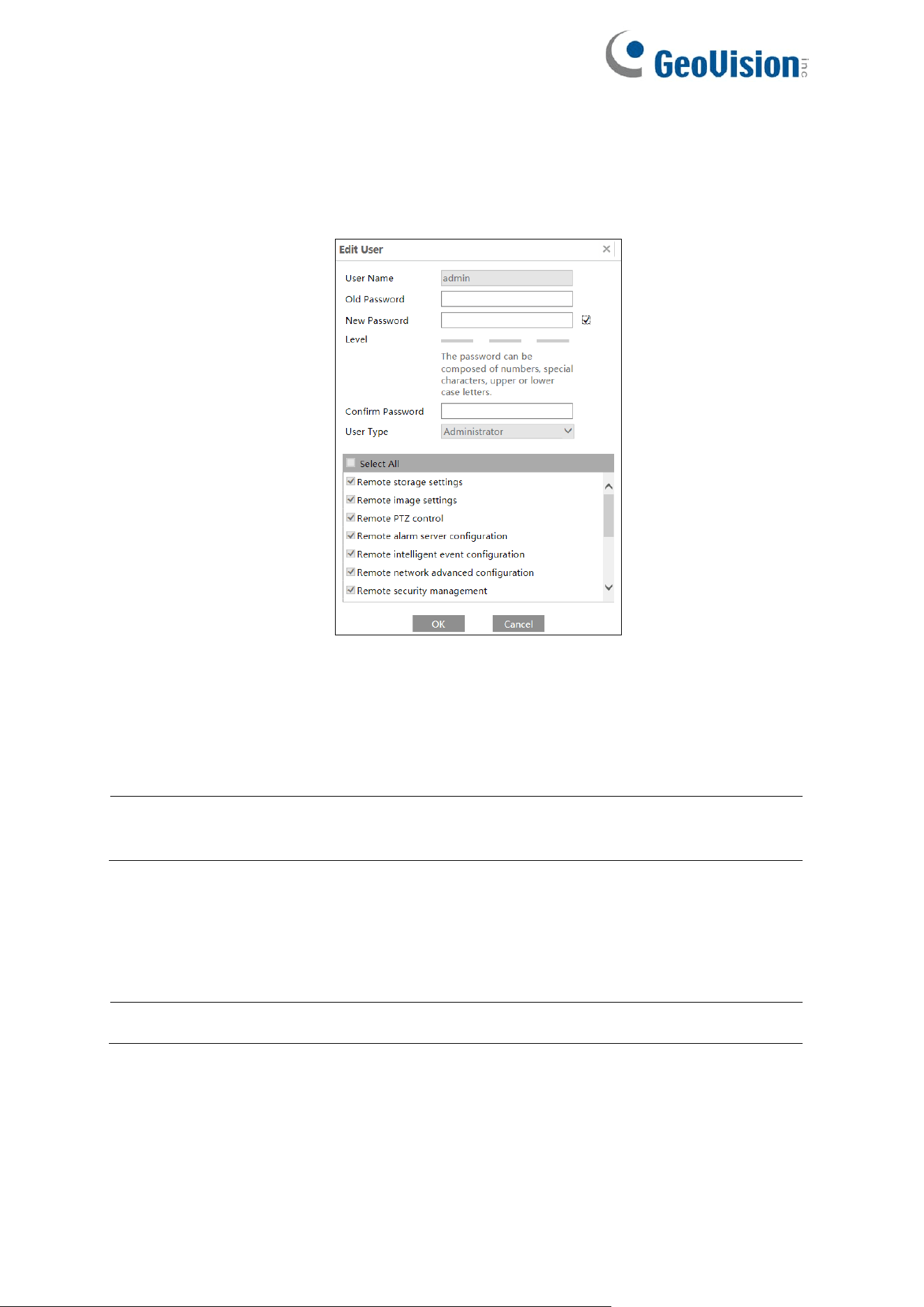
112
Modify user:
1. Select a user to modify password in the user configuration list box.
2. The “Edit user” dialog box pops up by clicking the “Modify” button.
3. Enter the old password of the user in the “Old Password” text box.
4. Enter the new password in the “New password” and “Confirm Password” text box.
5. Select the user permissions for advanced or normal user.
6. Click the “OK” button to save the settings.
Note: When the password level is set to “Strong”, the password cannot be set the same
as the previous five.
Delete user:
1. Select the user to be deleted in the user configuration list box.
2. Click the “Delete” button to delete the user.
Note: The default administrator account cannot be deleted.
Safety Question Settings: Set the questions and answers for admin to reset the password
after you forget the password. You can set the account security question during the activation,
or you can go to Config→Security→User, and click Safety Question. Select the security
questions and input your answers.
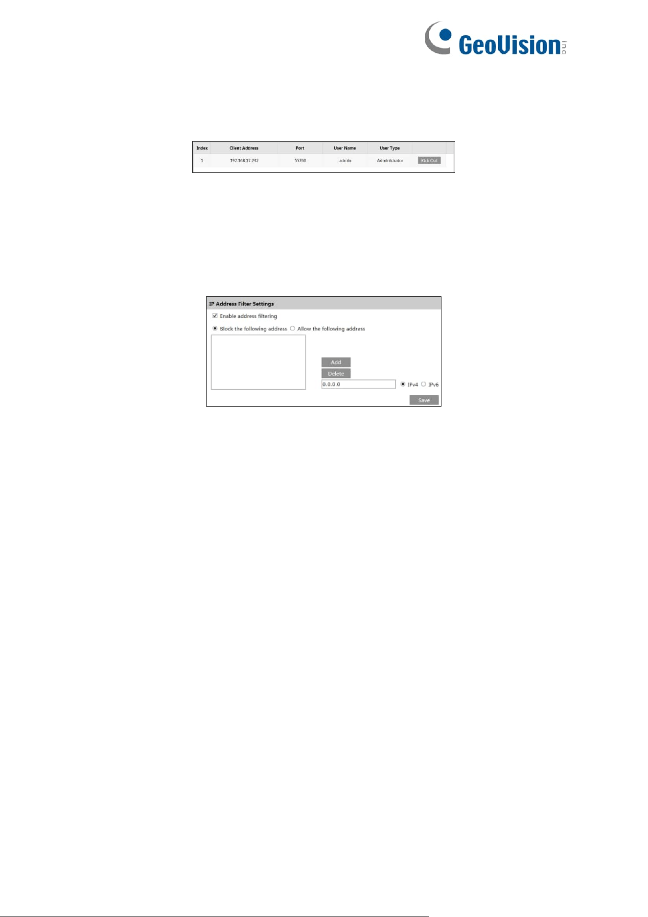
113
4.7.2 Online User
Go to Config→Security→Online User to view the user who is viewing the live video.
An administrator user can kick out all the other users (including other administrators).
4.7.3 Block and Allow Lists
Go to Config→Security→Block and Allow Lists as shown below.
The setup steps are as follows:
Check the “Enable address filtering” check box.
Select “Block/Allow the following address”, IPv4/IPv6 and then enter IP address in the
address box and click the “Add” button.
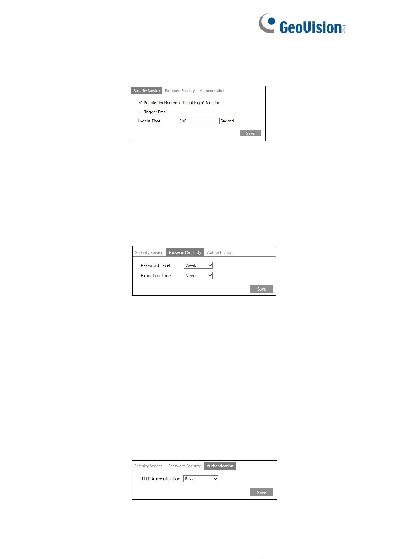
114
4.7.4 Security Management
Go to Config→Security→Security Management as shown below.
⚫ Security Service
In order to prevent against malicious password unlocking, “locking once illegal login”
function can be enabled here. If this function is enabled, login failure after trying six times
will make the login interface locked. The camera can be logged in again after a half hour
or after the camera reboots.
Trigger Email: if enabled, e-mail will be sent when logging in/out or illegal login lock
occurs.
⚫ Password Security
Please set the password level and expiration time as needed.
Password Level: Weak, Medium or Strong.
⚫ Weak: Numbers, special characters, upper- or lower-case letters can be used. You
can choose one of them or any combination of them when setting the password.
⚫ Meddle: 8~16 characters, including at least two of the following categories: numbers,
special characters, upper-case letters and lower-case letters.
⚫ Strong: 8~16 characters. Numbers, special characters, upper case letters and
lower-case letters must be included.
For your account security, it is recommended to set a strong password and change your
password regularly.
⚫ HTTP Authentication
Basic or Token is selectable.
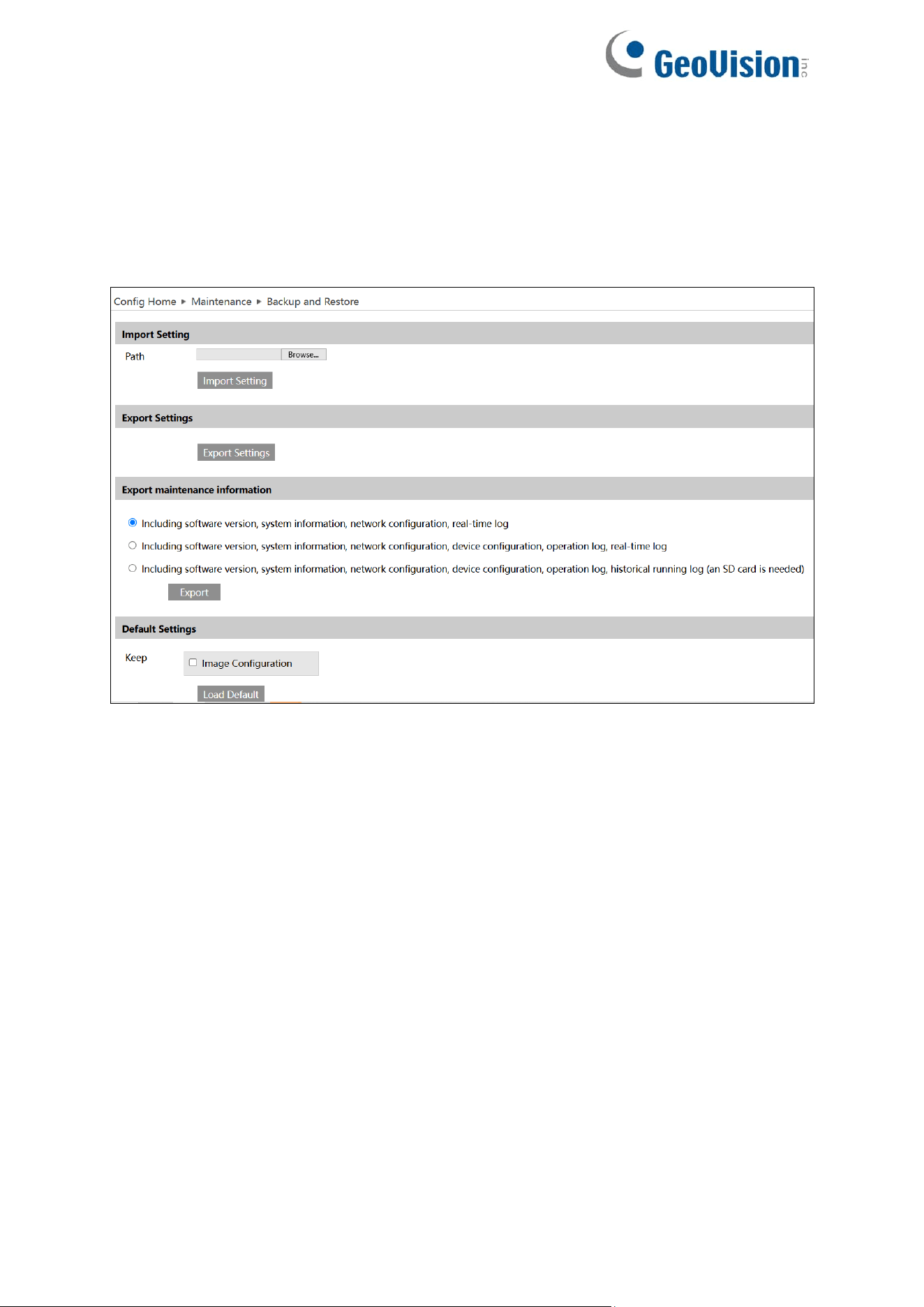
115
4.8 Maintenance Configuration
4.8.1 Backup and Restore
Go to Config→Maintenance→Backup and Restore.
GV-GEBF4911
⚫ Import & Export Settings
Configuration settings of the camera can be exported form a camera into another camera.
1. Click “Browse” to select the save path for import or export information on the PC.
2. Click the “Import Setting” or “Export Setting” button.
⚫ Default Settings
Click the “Load Default” button to restore all system settings to the default factory settings
except those you want to keep.
⚫ Export Maintenance Information
When the device failure occurs, you can export the maintenance information and send it to the
technicians, so that they can quickly find out and analyze the problem.
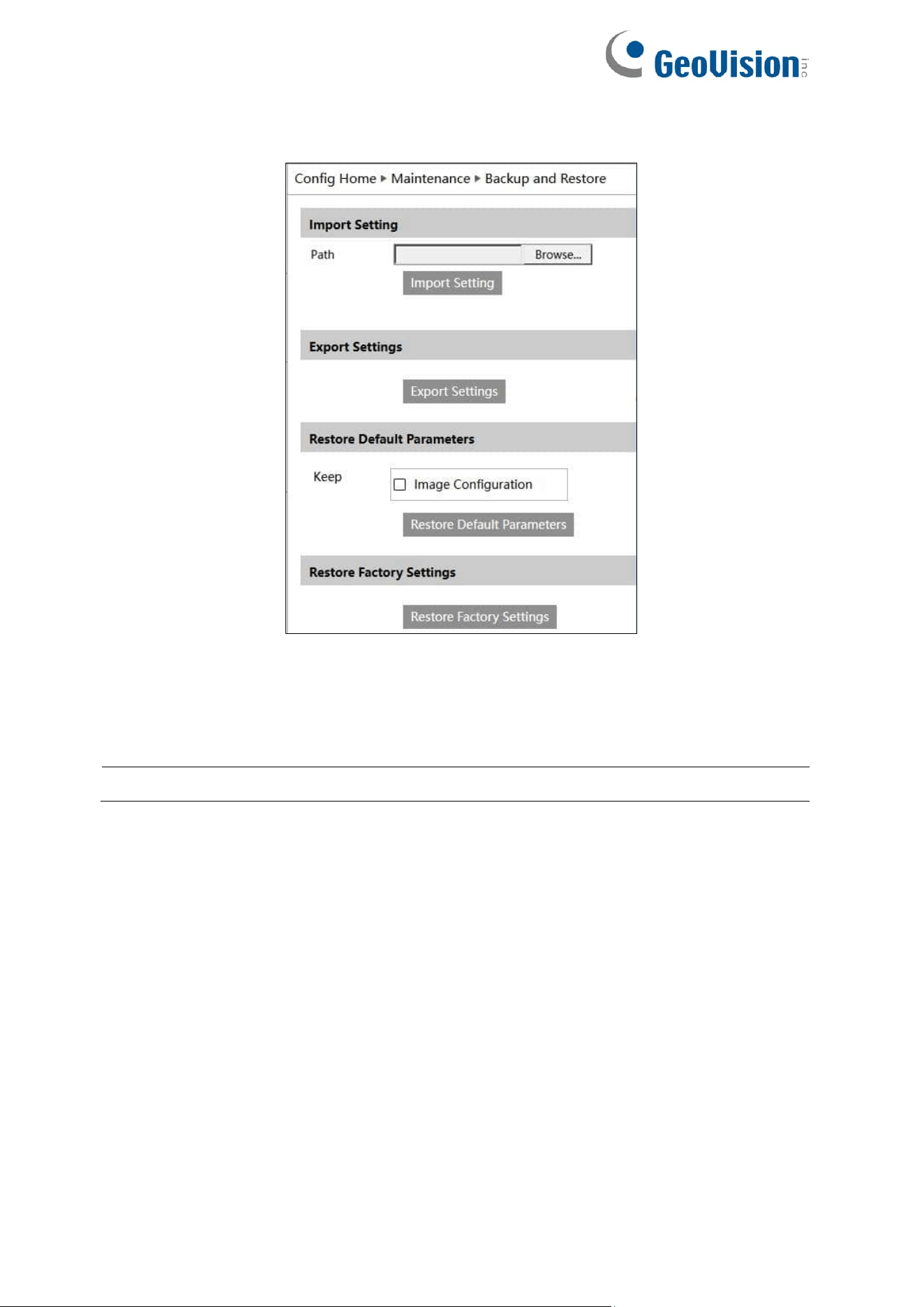
116
GV-GBL4900 / GBL4911 / GDR4900 / GEB4900 / GFER6900 / GVD4910
⚫ Import & Export Settings
Configuration settings of the camera can be exported form a camera into another camera.
1. Click “Browse” to select the save path for import or export information on the PC.
2. Click the “Import Setting” or “Export Setting” button.
Note: The login password needs to be entered after clicking the “Import Setting” button.
⚫ Restore Factory Settings
Click the “Restore Factory Settings” button and then verify the password to restore all system
settings to the default factory settings. Or, select the “Keep Image Configuration” option to
remain passwords and image configurations after restoring defaults.
117
4.8.2 Reboot
Go to Config→Maintenance→Reboot.
Click the “Reboot” button to reboot the device.
Timed Reboot Setting:
If necessary, the camera can be set up to reboot on a time interval. Enable “Time Settings”,
set the date and time and then click the “Save” button to save the settings.
4.8.3 Upgrade
Go to Config→Maintenance→Upgrade. In this interface, the camera firmware can be
updated.
1. Click the “Choose File” / “Browse” button to select the save path of the upgrade file.
2. Click the “Upgrade” or “Back up and upgrade” button to start upgrading the firmware.
3. Enter the correct password and then the device will restart automatically
Export Upgrade Log: If upgrade error occurs, the upgrade log can be exported to help the
technician to analyze and solve the problem.
In case of failed upgrade, power off and power on the camera for 40 seconds, and repeat it for
7 times to switch to another system.
IMPORTANT:
1. Do not allow downgrading from the current version to the lower version.
2. Do not close the browser or disconnect the camera from the network during the
upgrade, or it will cause system failure. After the device is successfully upgraded,
there are ten minutes of observation. During this observation period, do not upgrade
the device again.
Note:
1. If “Back up and upgrade” is selected, the configuration file will be exported to your
local PC before starting upgrading.
2. To decrease the upgrade risk, the camera adopts two systems. After one system is
successfully upgraded, the other system will be synchronized. If one system fails
caused by power failure or other reasons during the upgrade, the other system will
not be affected and the camera still can work normally. You can also upgrade your
camera through the normal system.
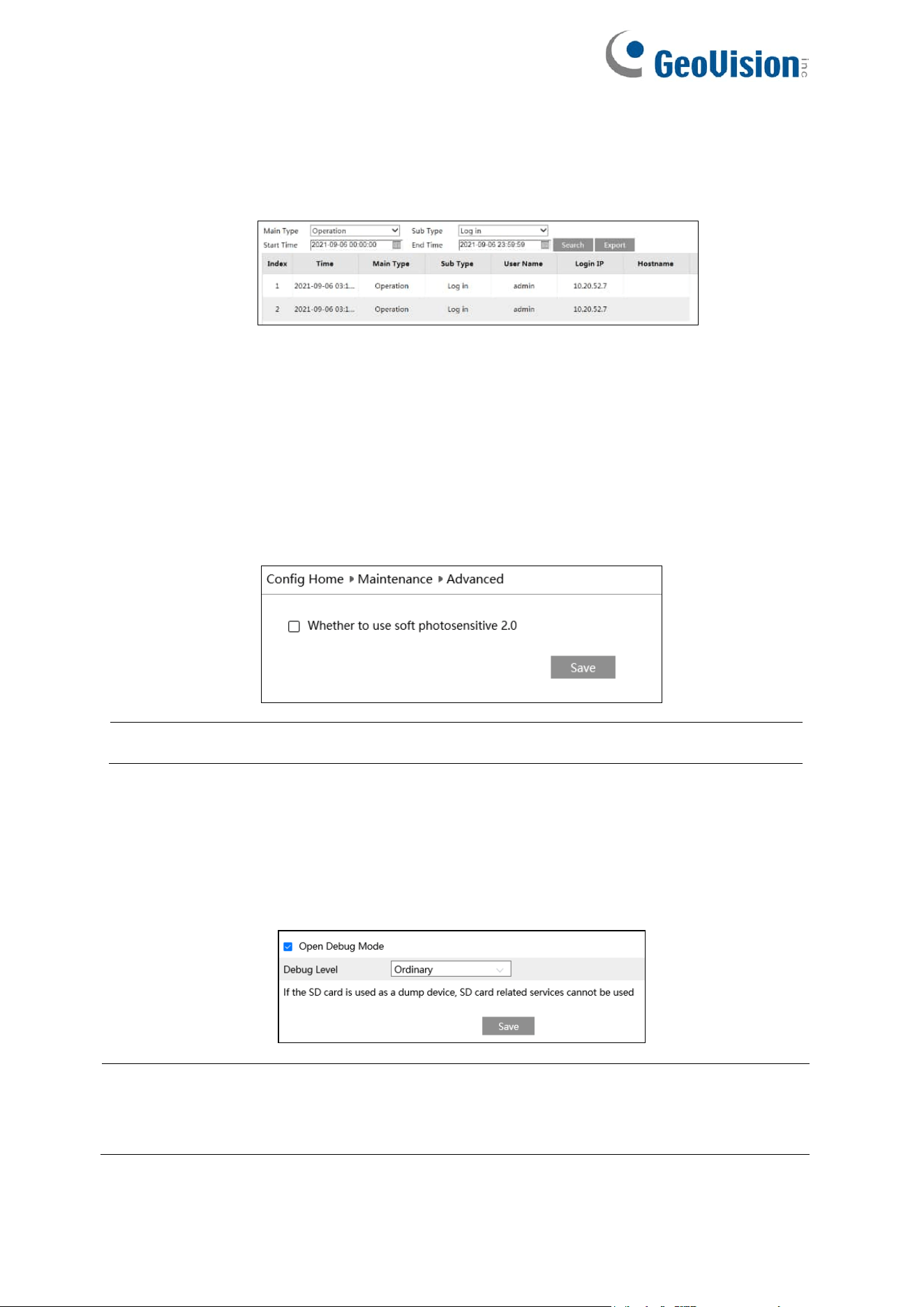
118
4.8.4 Operation Log
To query and export log:
1. Go to Config→Maintenance→Operation Log.
2. Select the main type, sub type, start and end time.
3. Click “Search” to view the operation log.
4. Click “Export” to export the operation log.
4.8.5 Advanced
The software photosensitive 2.0 function is used to enable software light sensitivity mode
depending on the setup environment.
Note: The Advanced setting is not applicable to GV-GEBF4911 / GFER6900.
4.8.6 Debug Mode
Debug Mode is used to record and collect the required system data, so that the technician can
quickly find out and analyze the problem, and help us to improve service.
Before enabling the debug mode, you are advised to consult our technical support.
Note: Once the SD card is used to collect the system data, the SD card will not be used to
store snapshots and recorded files. Only when you disable debug mode and format the SD
card in the storage interface (Config→System→Storage→Management) after the device is
rebooted, can the SD card be used to store snapshots and recorded files.
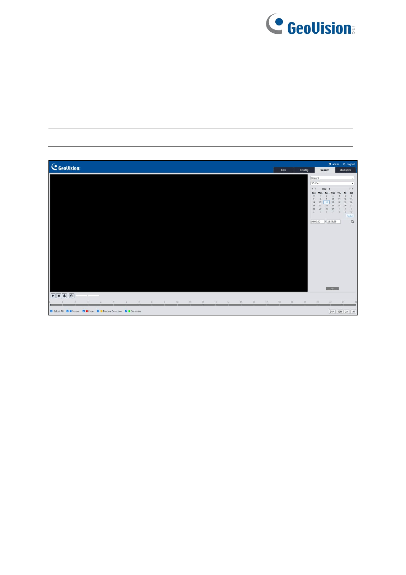
119
Chapter 5 Search
5.1 Image Search
Click Search to go to the interface as shown below. Images that are saved on the SD card can
be found here.
Note: Local images can only be searched in the browsers supporting plugins.
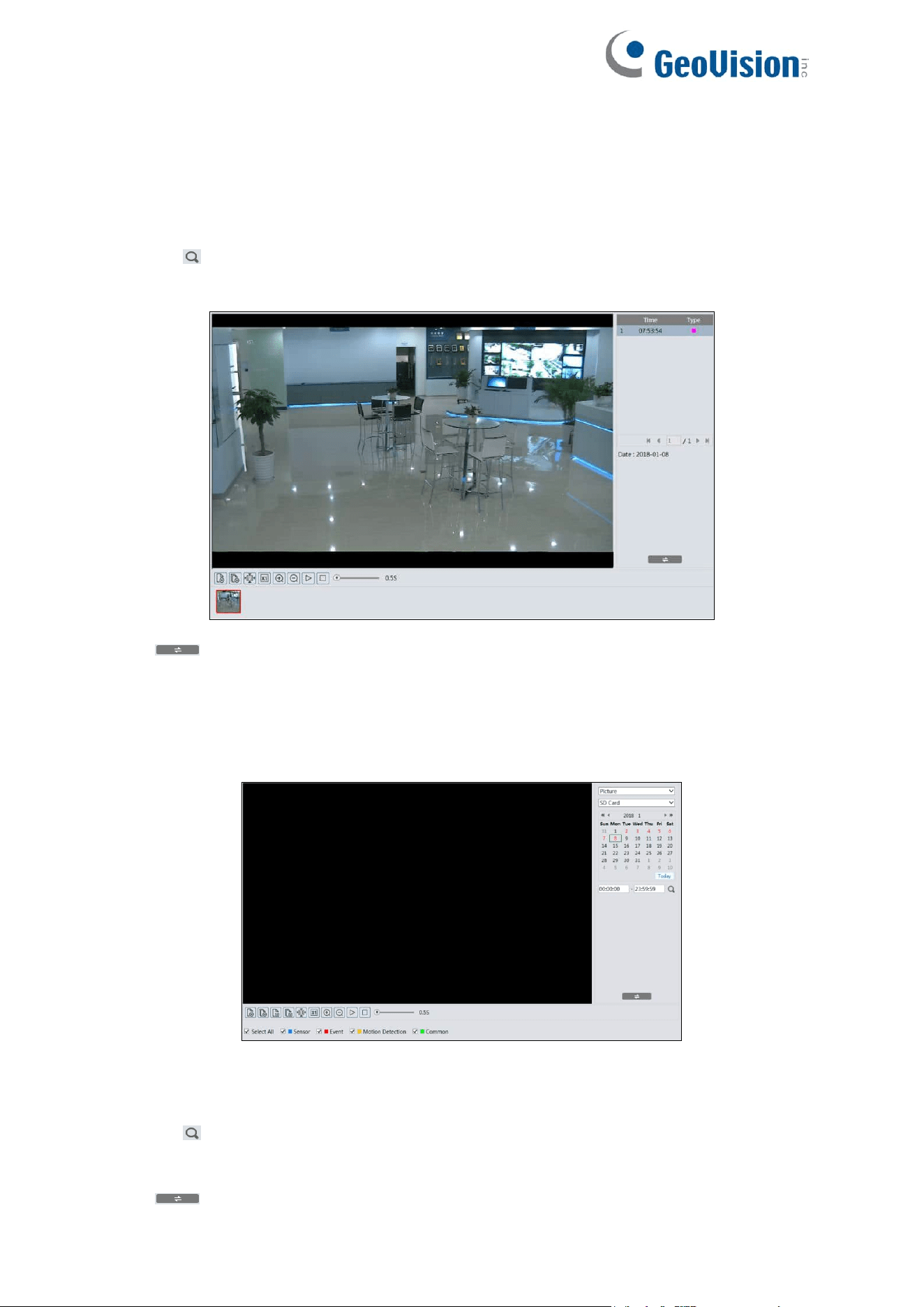
120
For GV-GEBF4911
⚫ Local Image Search
1. Choose “Picture”—“Local”.
2. Set time: Select date and choose the start and end time.
3. Click to search the images.
4. Double click a file name in the list to view the captured photos.
Click to return to the previous interface.
⚫ SD Card Image Search
1. Choose “Picture”—“SD Card”.
2. Set time: Select date and choose the start and end time.
3. Choose the alarm events at the bottom of the interface.
4. Click to search the images.
5. Double click a file name in the list to view the captured photos.
Click to return to the previous interface.
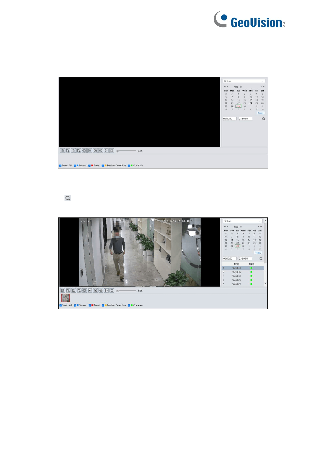
121
GV-GBL4900 / GBL4911 / GDR4900 / GEB4900 / GFER6900 / GVD4910
⚫ SD Card Image Search
1. Choose “Picture”.
2. Set time: Select date and choose the start and end time.
3. Choose the alarm events at the bottom of the interface.
4. Click to search the images.
5. Double click a file name in the list to view the captured photos.
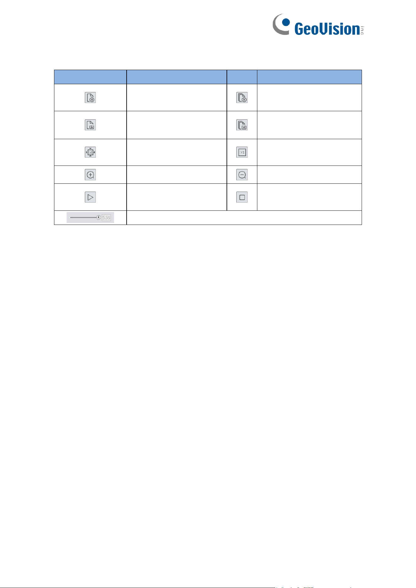
122
The descriptions of the buttons are shown as follows.
Icon
Description
Icon
Description
Close: Select an image
and click this button to
close the image.
Close all: Click this button to
close all images.
Save: Click this button to
select the path for saving
the image on the PC.
Save All: Click this button to
select the path for saving all
pictures on the PC.
Proper Size: Click to fit the
image on the screen.
Actual size: Click this button
to display the actual size of
the image.
Zoom in: Click this button
to digitally zoom in.
Zoom out: Click this button
to digitally zoom out.
Slide show play: Click this
button to start the slide
show mode.
Stop: Click this button to
stop the slide show.
Play speed: Play speed of the slide show.
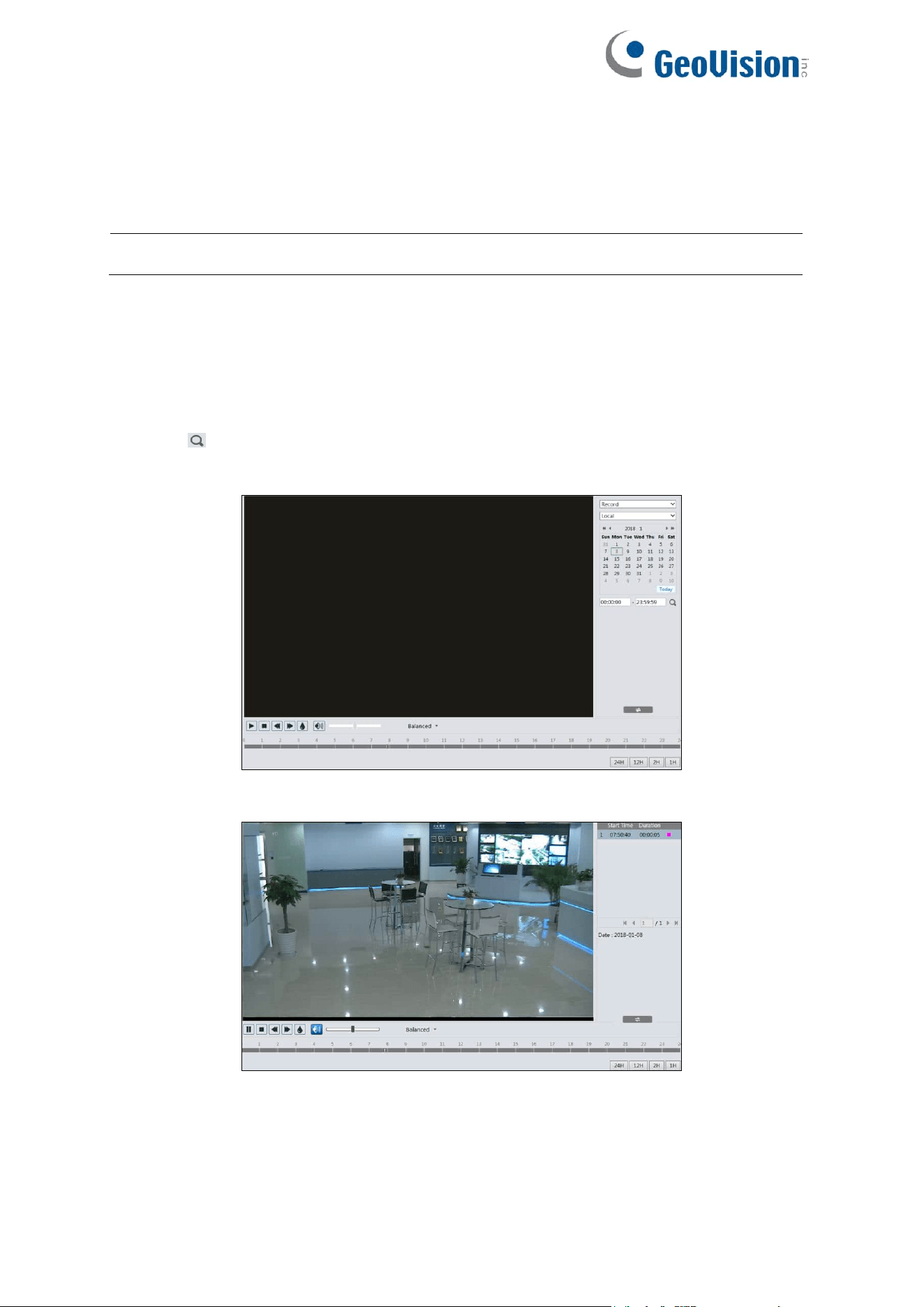
123
5.2 Video Search
Click Search to go to the interface as shown below. Videos were recorded locally to the PC /
save in the SD card can be played in this interface.
Note: Local videos can only be searched in the browsers supporting plugins.
For GV-GEBF4911
⚫ Local Video Search
1. Choose “Record”—“Local”.
2. Set search time: Select the date and choose the start and end time.
3. Click to search the images.
4. Double click on a file name in the list to start playback.
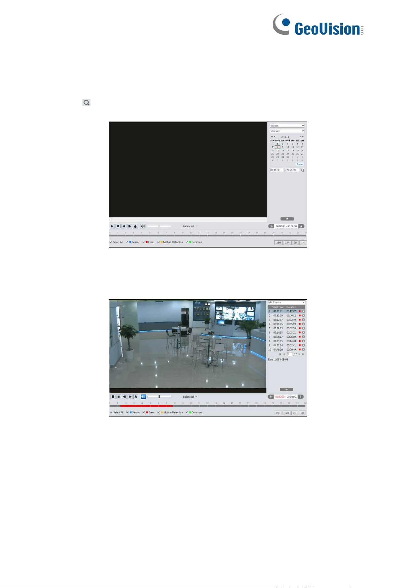
124
⚫ SD Card Video Search
1. Choose “Record”—“SD Card”.
2. Set search time: Select the date and choose the start and end time.
3. Click to search the images.
4. Select the alarm events at the bottom of the interface.
5. Select mix stream (video and audio stream) or video stream as needed.
6. Double click on a file name in the list to start playback.
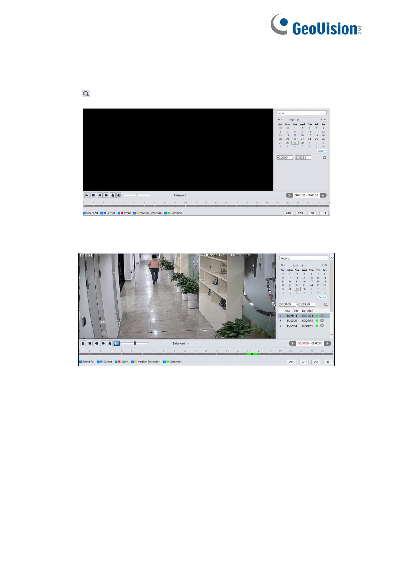
125
For GV-GBL4900 / GBL4911 / GDR4900 / GEB4900 / GFER6900 / GVD4910
1. Choose “Record”.
2. Set search time: Select the date and choose the start and end time.
3. Click to search the images.
4. Select the alarm events at the bottom of the interface.
5. Double click on a file name in the list to start playback.
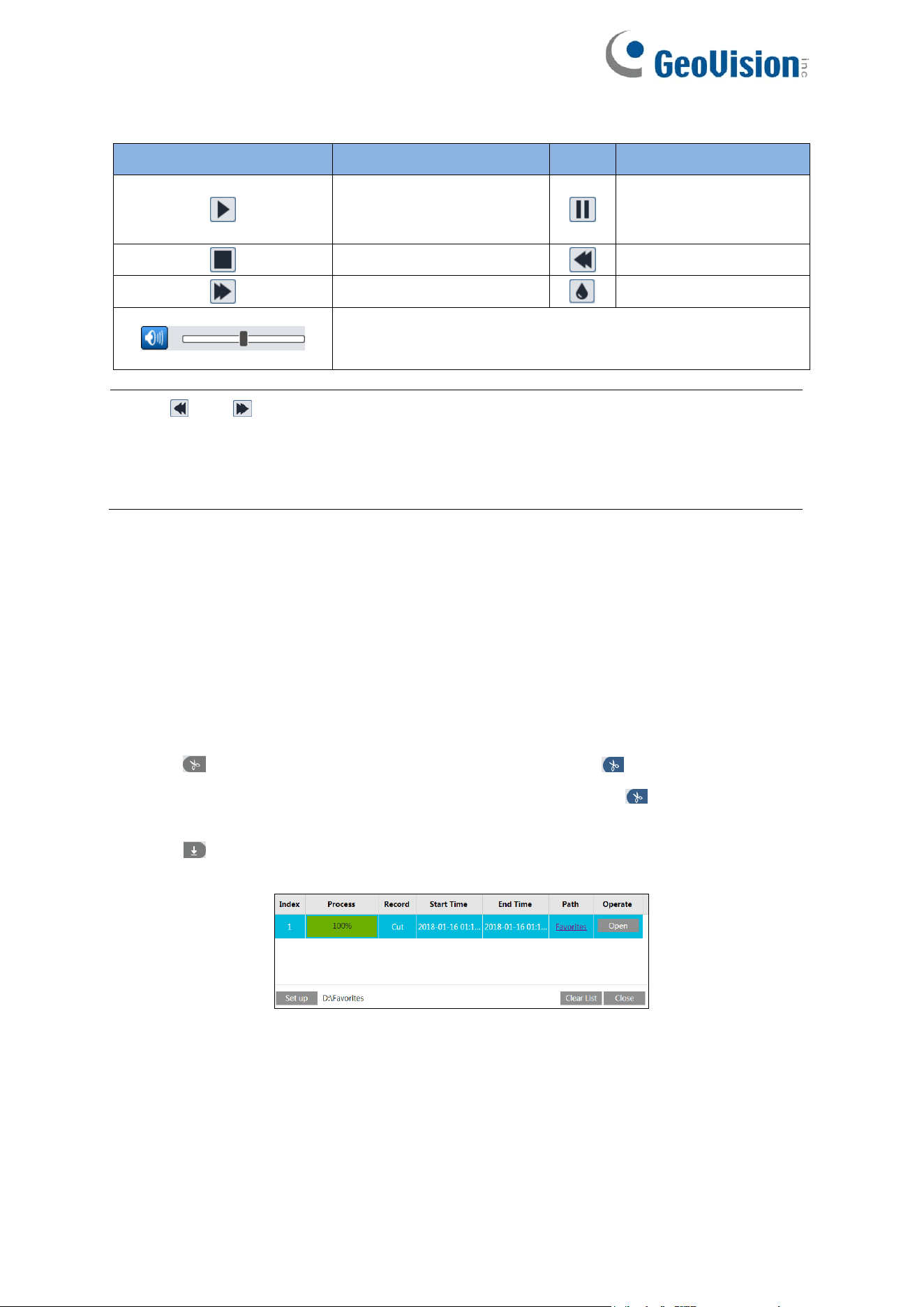
126
Icon
Description
Icon
Description
Play button. After pausing
the video, click this button
to continue playing.
Pause button
Stop button
Speed down
Speed up
Watermark display
Enable / disable audio; drag the slider to adjust the volume
after enabling audio.
Note: and can only be displayed in the above interface via the browsers
supporting plugins.
Additionally, playback mode switch (balanced / real-time / fluent mode) and downloading
functions are also only supported in the browsers supporting plugins.
The time table can be shown in 24H / 12H / 2H / 1H format by clicking the corresponding
buttons.
Video clip and downloading
1. Search the video files according to the above-mentioned steps.
2. Select the start time by clicking on the time table.
3. Click to set the start time and then this button turns blue .
4. Select the end time by clicking on the time table. Then click the button to set the end
time.
5. Click to download the video file in the PC.
Click “Set up” to set the storage directory of the video files.
Click “Open” to play the video.
Click “Clear List” to clear the downloading list.
Click “Close” to close the downloading window.
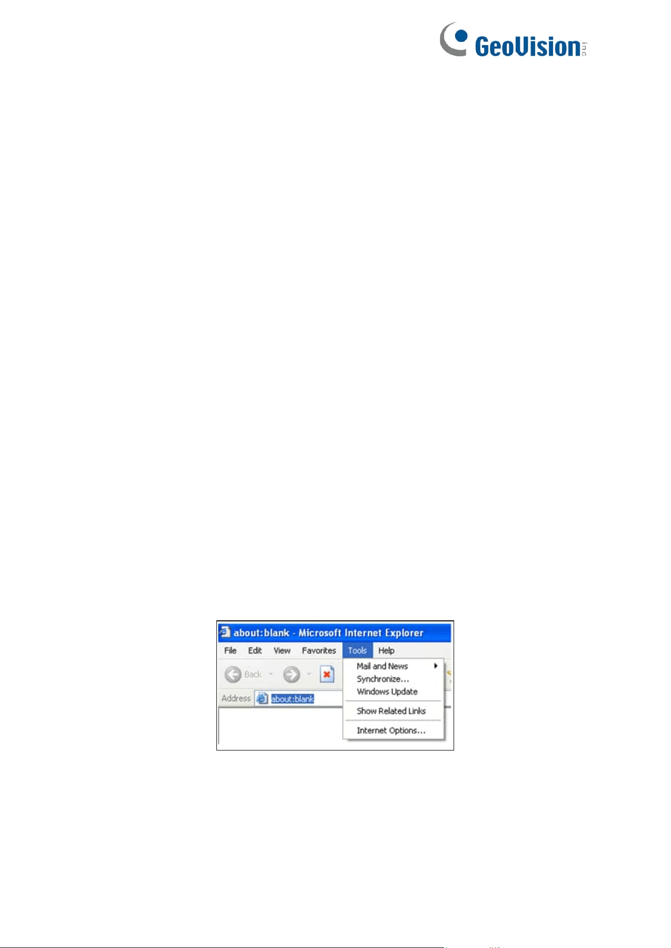
127
Appendix
Appendix 1 Troubleshooting
How to find the password?
A: The password for admin can be reset through “Edit Safety Question” function.
Click “Forget Password?” on the login page and enter the corresponding answer of the
selected question in the popup window. After you correctly answer all questions, you can
reset the password for admin. If you forget the answer of the question, this way will be invalid,
please contact your dealer for help.
B: The passwords of other users can be reset by admin.
Fail to connect devices through a browswer.
A: Network is not well connected. Check the connection and make sure it is connected well.
B: IP address is not available. Reset the IP address.
C: Web port number has been changed: contact administrator to get the correct port number.
D: Exclude the above reasons. Restore to default setting by IP-Tool.
IP tool cannot search devices.
It may be caused by the anti-virus software in your computer. Please exit it and try to search
device again.
IE mode in Microsoft Edge does not support downloading plugins.
A. IE mode in Microsoft Edge may be set up to block plugins. Follow the steps below.
1. Open IE mode in Microsoft Edge and then click Tools→Internet Options.
2. Select Security→Custom Level.
3. Enable all the options under the plugins.
4. Click OK to finish setup.
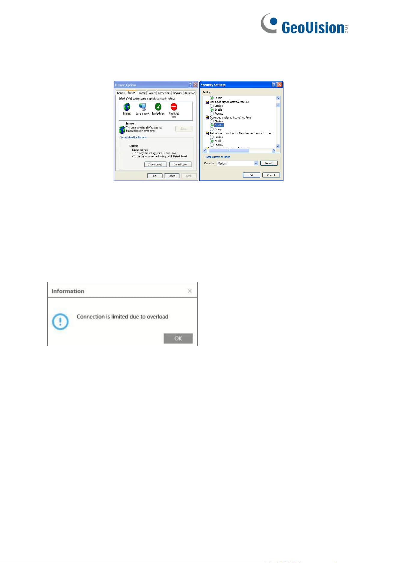
128
B. Other plugins or anti-virus blocks plugins. Please uninstall or close them.
No sound can be heard.
A: Audio input device is not connected. Please connect and try again.
B: Audio function is not enabled at the corresponding channel. Please enable this function.
What’s the Web/ONVIF/RTSP connection limit?
A maximum of 6 connections of Web/ONVIF/RTSP is supported. When the connection
exceeds the specification, the following message pops up:
129
Appendix 2 Configuration Requirements and Surrounding
Area
1. Auto-focusing function should not be enabled. Enabling auto-focusing may cause
significant changes in the picture, leading to temporary algorithm interruption.
2. Try to avoid excessive obstruction from trees, while also avoiding excessive variations in
lighting conditions in the scene, such as frequent and excessive car headlights, etc., to
improve the accuracy of intelligent functions. The brightness of the scene should not be
too low, as excessively dim scenes will reduce the accuracy of alarms. Adequate lighting
and clear scenery are important conditions.
3. The optimal overhead angle for the camera is between 30 degrees and 45 degrees (see
outdoor installation diagram for 12 mm lens).
For pedestrians: It is necessary to include the upper body, with the head and torso.
For vehicles: The downward angle should not be too large (not exceeding the
recommended angle). Oblique and horizontal views are preferred over downward views,
and it is recommended to install the camera with an oblique view.
4. When the camera is detecting, the target should spend at least about 2 seconds passing
through the detection area.
5. Not suitable for scenes with significant changes in lighting.
6. Adjust the camera so that the area needing protection is positioned as centrally as
possible within the field of view. There should be no obstructions in the main thoroughfare
areas. Try to exclude swaying obstructions such as trees, bushes, flags, etc., from the
detection area.
7. Please adjust the camera's installation position or focal length so that the targets of
interest in the frame meet certain size requirements. Optimal target recognition sizes:
The proportion here refers to the ratio of the target's width to the width of the frame. For
example, in a resolution of 1920×1080, the minimum resolution for a person would be 80×160
(w=1920×4%=80, h=1920×8%=160).
Percentage
Human
Motor Vehicle
Motorcycle/Bicycle
Minimum
(Width × Height)
4% × 8%
8% × 8%
4% × 4%
Maximum
(Width × Height)
50%× 50%
50%× 50%
50%× 50%
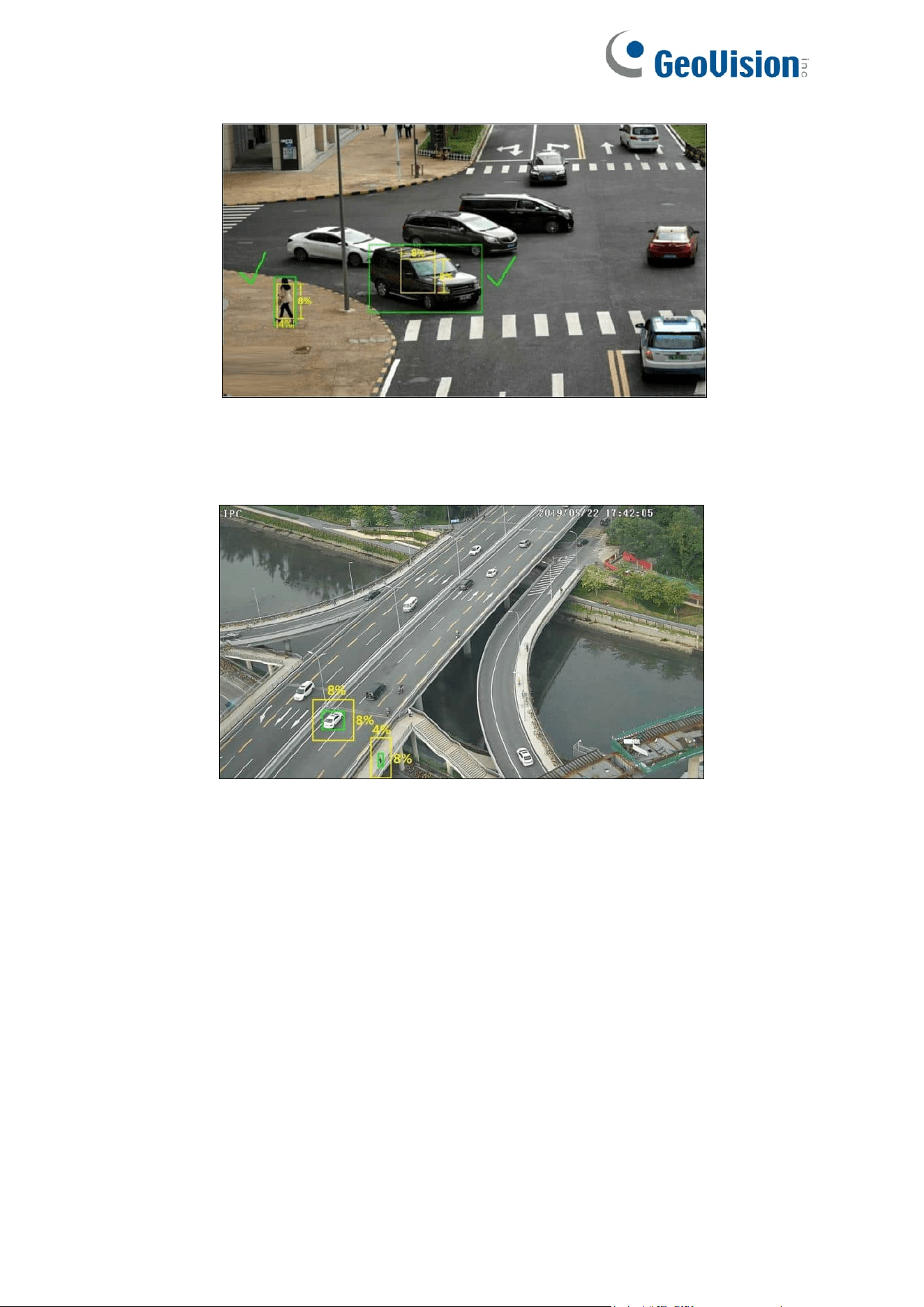
130
Correct example: The target meets the minimum size requirements. The yellow box in the
image represents the minimum detection box.
Incorrect example: The target does not meet the minimum size requirements. The yellow
box in the image represents the minimum detection box.
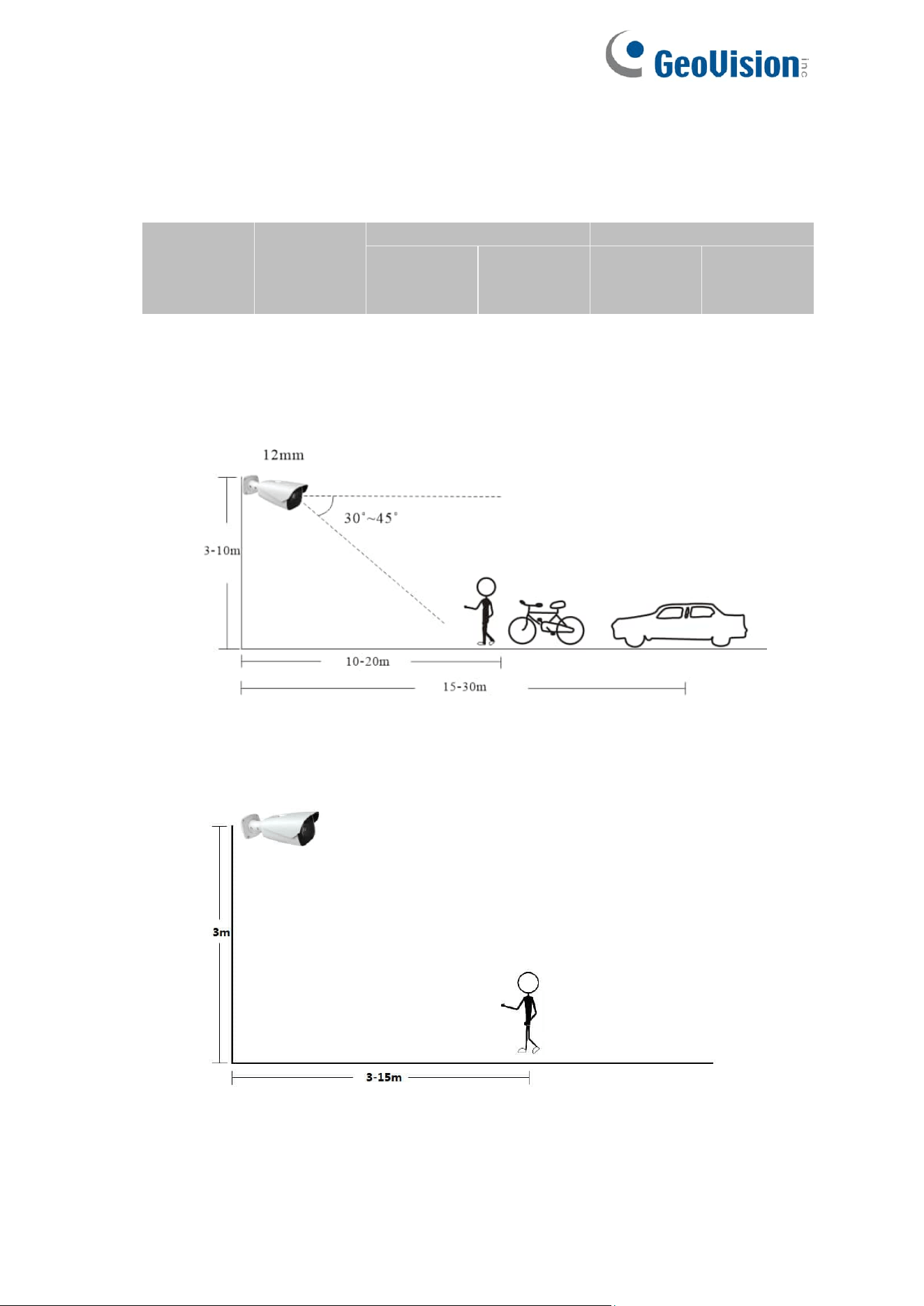
131
8. Installation suggestion:
Outdoor mounting:
The optimal detection distance varies due to different focal length. Please refer to the
following table.
Focal
Length
Installation
Height (m)
Human/Motorcycle/Bicycle
Motor Vehicle
Maximum
Distance
(m)
Optimal
Distance
(m)
Maximum
Distance
(m)
Optimal
Distance
(m)
2.8 mm
3-10
8
4-8
15
10-15
3.6 mm
3-10
10
5-10
20
15-20
12 mm
3-10
25
10~20
35
15~30
22 mm
3-10
45
30~40
70
20~50
Example for 12 mm focal length
Indoor Mounting: