
FeelTech
FY2300H Series Fully Numerical Control
Dual Channel Function/Arbitrary
Waveform Generator
User’s Manual
Rev2.1 May,2016


FeelTech
FY2300H Series User’s Manual I
Guaranty and Declaration
Copyright
© 2016 FeelTech Technology Co. Ltd. All Rights Reserved.
Trademark Information
FeelTech is a registered trademark of FeelTech Technology Co. Ltd.
Declaration
FeelTech reserves the right to modify or change parts of or all the
specifications and pricing policies at company’s sole decision.
Information in this publication replaces all previously corresponding material.
FeelTech shall not be liable for losses caused by either incidental or
consequential in connection with the furnishing, use or performance of this
manual as well as any information contained.
Any part of this document is forbidden to be copied or photocopied or
rearranged without prior written approval of FeelTech。
Contact Us
If you have any problem or requirement when using our products or this
manual, please contact FeelTech.
Tel
:
0086 371 68997005 E-mail
:
Website:www.feeltech.net

FeelTech
II FY2300H Series User’s Manual
Contents
Guaranty and Declaration...................................................................................................I
Brief Introduction................................................................................................................. 1
Quick Start.............................................................................................................................. 4
General Inspection
..........................................................................................................
4
Front Panel Overview.....................................................................................................5
Right Panel Overview.....................................................................................................7
Left Panel Overview........................................................................................................8
Power On and Inspection..............................................................................................9
User Interface................................................................................................................ 10
Appearance and Dimensions.....................................................................................12
Front Panel Operations
....................................................................................................
14
Waveform Output..........................................................................................................14
Select Output Channel........................................................................................................14
Select Waveform..................................................................................................................15
Set Frequency......................................................................................................................16
Set Amplitude....................................................................................................................... 17
Set Offset.............................................................................................................................. 19
Set Duty Cycle (Square).....................................................................................................20
Set Phase..............................................................................................................................21
Enable Output...................................................................................................................... 22
Example:Output Sine Waveform....................................................................................23
Generate a Burst Waveform.......................................................................................25
Frequency Meter/Counter...........................................................................................26
Enable the Counter............................................................................................................. 26
Set the Counter....................................................................................................................27
Sweep..............................................................................................................................28
Sweep Object....................................................................................................................... 28
Sweep Start Position...........................................................................................................29
Sweep End Position............................................................................................................ 30
Sweep Time..........................................................................................................................31
Sweep Type.......................................................................................................................... 32
Enable Sweep Function......................................................................................................33
System Configuration and Auxiliary Functions
......................................................
34
Save and Load.....................................................................................................................35
Synchronization................................................................................................................... 36
Configuration........................................................................................................................ 37
Uplink.....................................................................................................................................38
Troubleshooting
.................................................................................................................
39
Technical Specification
....................................................................................................
40
Appendix
...............................................................................................................................
43

FeelTech
FY2300H Series User’s Manual 1
Brief Introduction
This manual applies to each model of FY2300H series Function/Arbitrary
Waveform Signal Generator. The last three characters of the model indicate the
up limit output of Sine Wave (MHz). For example, the “60M” of the Model
Number “FY2300H-60M” indicates the Sine wave maximum output frequency is
up to 60MHz.
FY2300H series Dual Channel Function/Arbitrary Waveform Generator is a
multifunctional signal generator product integrating Function Signal Generator,
Arbitrary Waveform Generator, Pulse Signal Generator, Noise Signal Generator,
Counter and Frequency Meter with excellent cost performance. This instrument
adopts large scale CMOS integrated circuit and high speed MCU microprocessor.
The internal circuit uses SPXO as the basic standard to guarantee the stability of
signals. Surface mounting technology improves interference immunity and
operational life span.
This instrument has double channels can output 31 preseted DDS signals
including Sine, Square, Triangle(Ramp), Rise Sawtooth, Fall Sawtooth, Lorenz
Pulse, Multitone, Noise, Cardiogram, Trapezoidal Pulse, Sinc Pulse, Narrow
Pulse, Gauss White Noise, AM, FM, Step and user-defined waveform. It can also
output TTL electric level. Both channels are completely independent
It has friendly human-machine mutual interface. 2.4 inch TFT Color LCD with
320
×
240 resolution can display all the parameters of both channels and current
functions of all buttons . Shortcut keys simplify all complicated operations and
save time. Users can be proficient after several minutes practice.
The advantages of this instrument in signal generating, waveform sweeping,
parameter measurement and other fields, make it to be the ideal equipment for
electronic engineers, laboratories, industry producing line, university, R&D
institutes and so on.
Main Features:
Adopt DDS technology to generate accurate, stable signal with low distortion.
Portable design with top grade aluminum alloy shell. Use DC5V power

FeelTech
2 FY2300H Series User’s Manual
adopter or 5V portable power for power supply.
2.4 inch TFT Color LCD with 320 × 240 resolution can display all the
parameters of both channels and current functions of all buttons .
Frequency output of Sine wave can be up to 60MHz. 250MSa/s sampling rate.
14 bits vertical resolution.
Complete independent dual channels can work at same time and phase
difference is adjustable.
Following function allows users to synchronize all or partial parameters of
CH2 to CH1.
Two instruments or more can be synchronized by TTL_IO interface.
Various Waveform:
Sine
Square
Triangle/Ramp
Rise Sawtooth
Fall Sawtooth
Lorenz Pulse
Multitone
Noise
Electrocardiogram (ECG)
Trapezoidal Pulse
Sinc Pulse
Narrow Pulse
Gauss White Noise
Step Triangle
Positive Step
Inverse Step
Positive Exponent
Inverse Exponent
Positive Falling Exponent
Inverse Falling Exponent
Positive Logarithm
Inverse Logarithm
Positive Falling Logarithm
Inverse Falling Logarithm
Linear FM
AM
FM
Positive Half Wave
Negative Half Wave
Positive Half Wave
Rectification
Negative Half Wave
Rectification
User-defined waveform
It has 16 positions for saving user-defined waveform. Waveform Length of
each one is 8192 and vertical resolution is 14 bits.
High frequency precision up to 10
-6
orders of magnitude.
Full range of 1μHz frequency resolution.
Minimum amplitude resolution can be up to 1 mV.

FeelTech
FY2300H Series User’s Manual 3
Duty cycle of each channel can be adjusted separately. Precision can be
0.1%.
Phase of two channels adjustable during 0~359.9°. Accuracy can be 0.1
°
.
Direct digital Setting covering full range of frequency without grading.
Sweep Function: It can sweep 4 properties of signals including frequency,
amplitude, offset and duty cycle. It has Linear and Logarithm two sweep types.
Sweep time can be up to 999.99S. Sweep starting point and end point can be
set arbitrarily.
It has pulse train burst output function. There has Manual Trigger, internal
CH2 Trigger, and External Trigger for your options. It can output 1~1048575
pulse trains.
-10V~+10V DC Offset function
(
<20MHz
)
. Resolution 0.01V.
Digital signal output function can output any 0~10V CMOS electric level.
Save function: It can save 20 sets user-set parameters and can be loaded at
anytime.
100M Frequency meter function: It can measure frequency, period, pulse
width and duty cycle. Max. frequency workable is 100MHz and Min.
frequency workable is 0.01 Hz.
Counter Function: It has 2 coupling measure modes including DC coupling
and AC coupling. This design can solve inaccuracy problem of AC coupling.
All parameters can be calibrated by internal program.
Powerful arbitrary waveform edit function: Users can download arbitrary
waveform to this instrument after edit through PC program which is included
in user CD.
Powerful communicating function. All functions can be controlled by PC
program and the communication protocol is open for secondary development.
Output short-circuit protection: All channels can work more than 60 seconds
when the load is short-circuited.
Can choose our FYV2000 series or FPA1000 series power amplifier to output
20W or higher signals in DC-2MHz width without any distortion. The highest
power can be up to 60W with our FPA1016 amplifier.

FeelTech
4 FY2300H Series User’s Manual
Quick Start
General Inspection
Please follow the items below when you receive a new FY2300H series
Function/Arbitrary Waveform Generator.
1. Inspect the shipping container for damage
Keep the damaged shipping container or cushioning material until the
contents of the shipment have been checked for completeness and the
instrument has passed both electrical and mechanical tests. The consigner or
carrier shall be liable for the damage to instrument resulting from shipment.
2. Inspect the instrument
In case of any damage, or defect, or failure, notify your FeelTech sales
representative.
3. Check the accessories
Please check the accessories according to the Appendix C ( packing lists). If
the accessories are incomplete or damaged, please contact your FeelTech sales
representative.
FeelTech
FY2300H Series User’s Manual 5
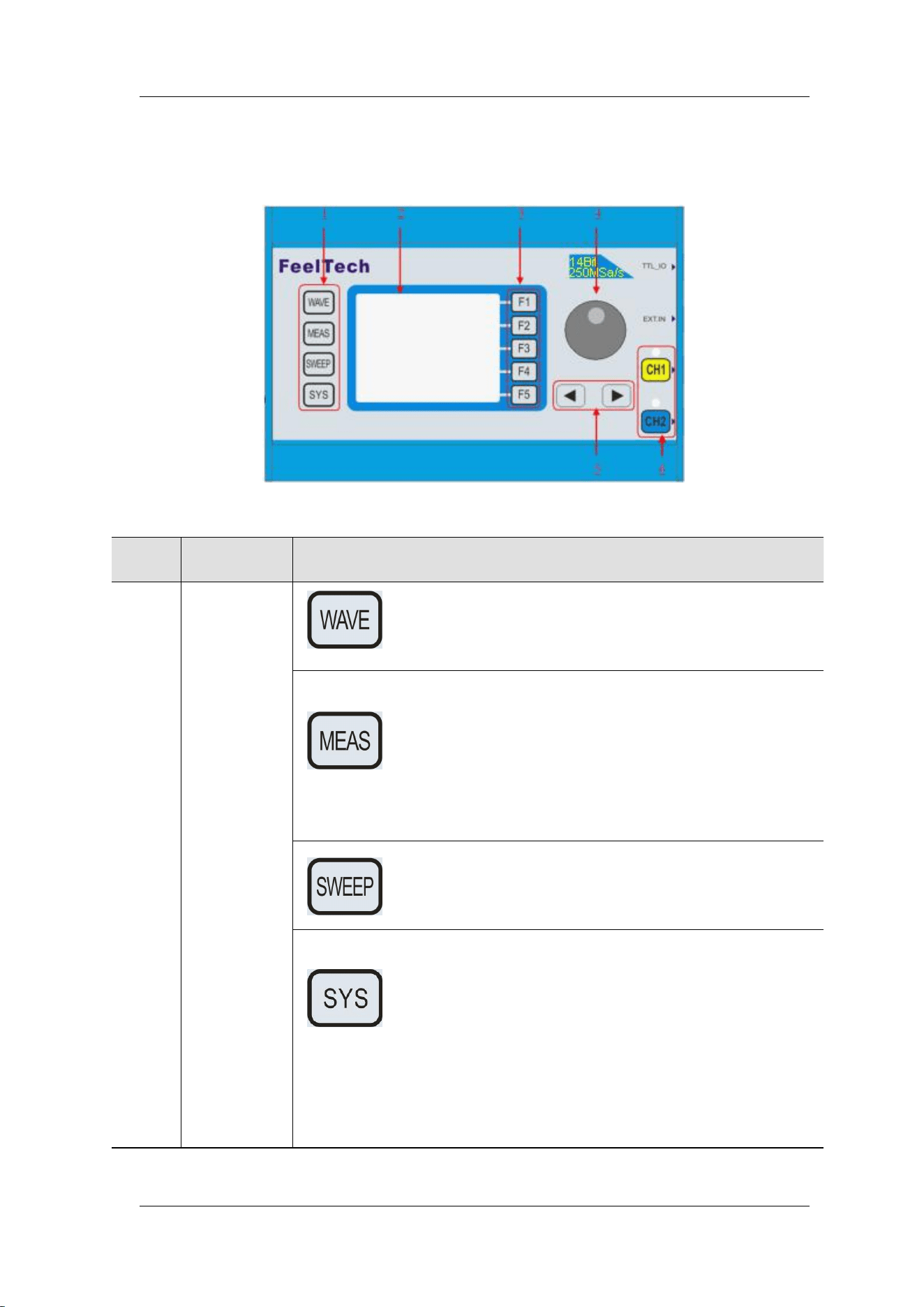
Front Panel Overview
The front panel is divided into several function areas for easy operation.
Front Panel
Item
Function
Description
1
Function
Buttons Area
Press this buttons to switch waveforms among Sine,
Square, Triangle and so on.
Press this button to switch between frequency meter and
counter to measure frequency, period, duty cycle and
pulse width of external signal output.
— Both DC and AC are workable.
— Gate Time can be 1S, 10S or 100S.
— Dual channels output and measurement function can
work together at same time.
Can sweep Sine, Square, Arbitrary and so on.
— Can sweep frequency, amplitude, offset and phase.
— 2 sweep types: Linear, Logarithm.
Auxiliary functions and system configuration setting.
— Can save 20 sets waveform parameters including
frequency, amplitude, offset, phase and so on.
— System Language has English and Chinese for
user’s option.
— Buzzer can be turned on/off in this manu.
— Set multimachine uplink.
— Switch Master-Slave status
— Set default status of dual channels at start-up.
FeelTech
6 FY2300H Series User’s Manual
2
LCD
2.4 inch TFT(320×240)color LCD. Operation instruction please
check chapter “User Interface”.
3
Manu
Buttons
F1~F5 buttons are matched with Manu displayed on the LCD.
Press corresponding button to activate submenu represented.
4
ADJ Knob
— Rotate the ADJ Knob to increase or reduce the current value
indicated by the cursor.
— Frequency unit can be changed by Press ADJ Knob under
Frequency value setting status.
— Press ADJ Knob to Start/Stop sweep under Sweep interface.
5
Arrows
Press Arrow buttons to select figure which you want to edit
when setting values of each parameter.
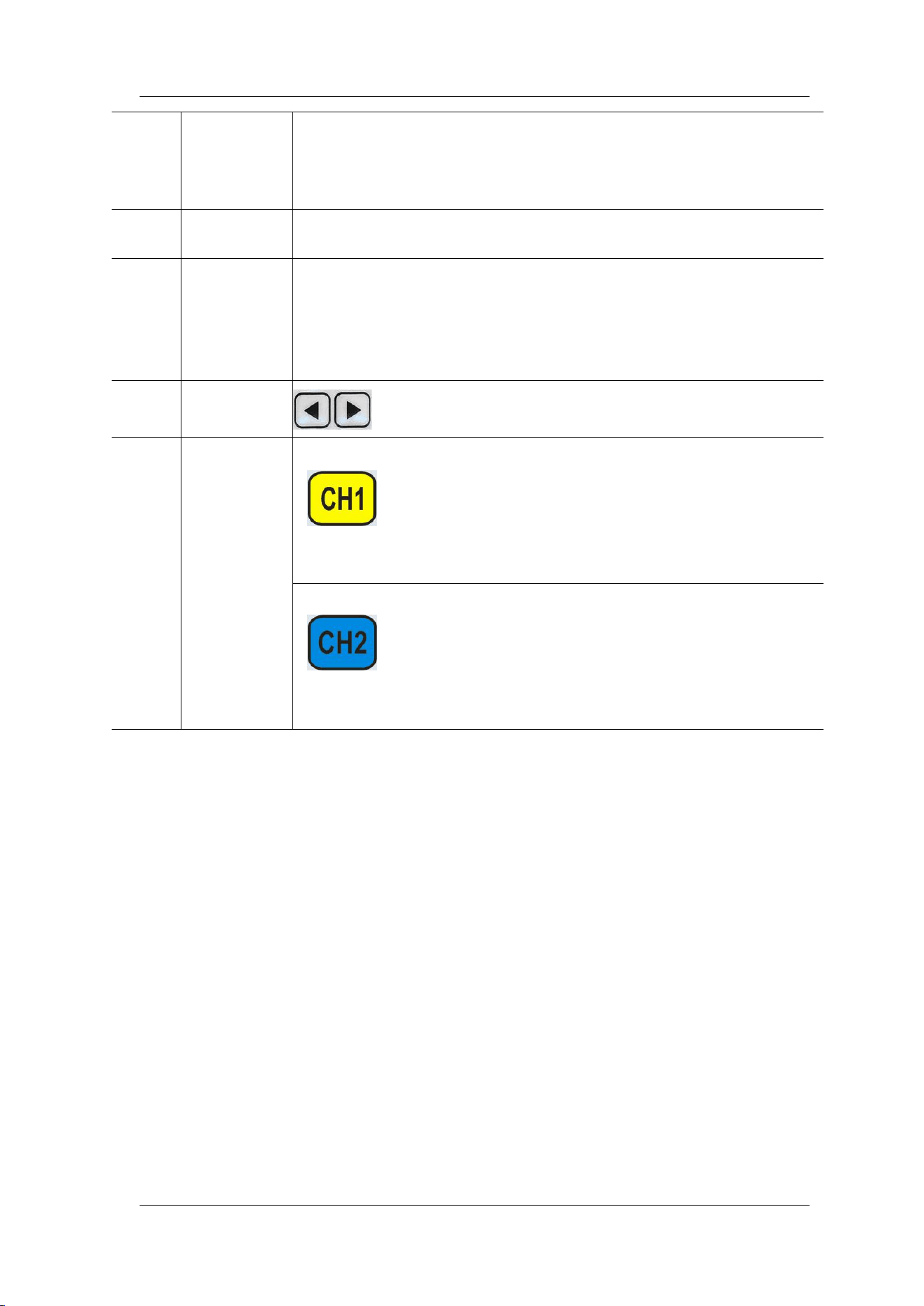
6
Output
Channels
Control CH1 output. Press it to switch to CH1 parameter
setting interface.
— Press it to turn on CH1 output with current
configuration. The indicator will illuminate.
— Press it again to turn off CH1 output and the indicator
will extinguish.
Control CH2 output. Press it to switch to CH2 parameter
setting interface.
— Press it to turn on CH2 output with current
configuration. The indicator will illuminate.
— Press it again to turn off CH2 output and the indicator
will extinguish.
FeelTech
FY2300H Series User’s Manual 7
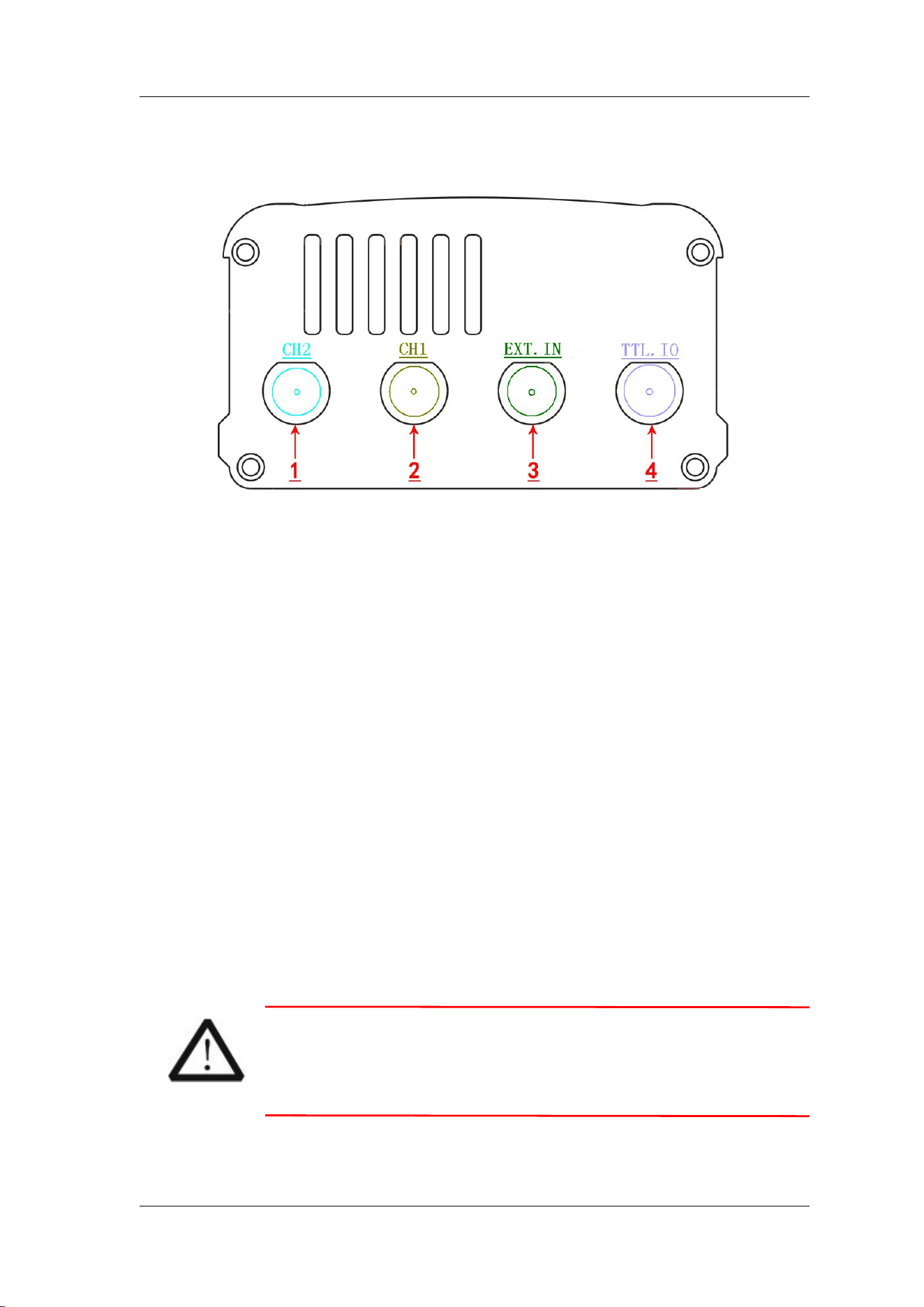
Right Panel Overview
Right Panel
1. CH2 BNC
It is a BNC (female) connector which nominal impedance is 50Ω. The
function of this connector is determined by the work mode of CH2.
2. CH1 BNC
It is a BNC (female) connector which nominal impedance is 50Ω. The
function of this connector is determined by the work mode of CH1.
3. EXT.IN Connector
It is a BNC (female) connector for inputting signals for measurement.
Impedance is 100KΩ.
4. TTL_IO Connector
It is a BNC (female) connector for outputting TTL signal synchronized with
CH1 and inputting uplink signal.
1) Under non-uplink status it can output 3.3 Vpp LVTTL signal synchronized
with CH1 and output impedance is no higher than 50Ω.
2) When uplink is enabled and work as slave, the connector works as external
signal input interface and input impedance is more than 100 KΩ. Please refer to
chapter “Synchronization”.
3) Under Measurement function, it is as digital signal input terminal (DC
Coupling).
Note:
Voltage of signal input CANNOT exceed ±20Vac+dc at EXT.IN
Terminal and CANNOT exceed DC5V at TTL_IO Terminal in
case any damage to this instrument.
FeelTech
8 FY2300H Series User’s Manual
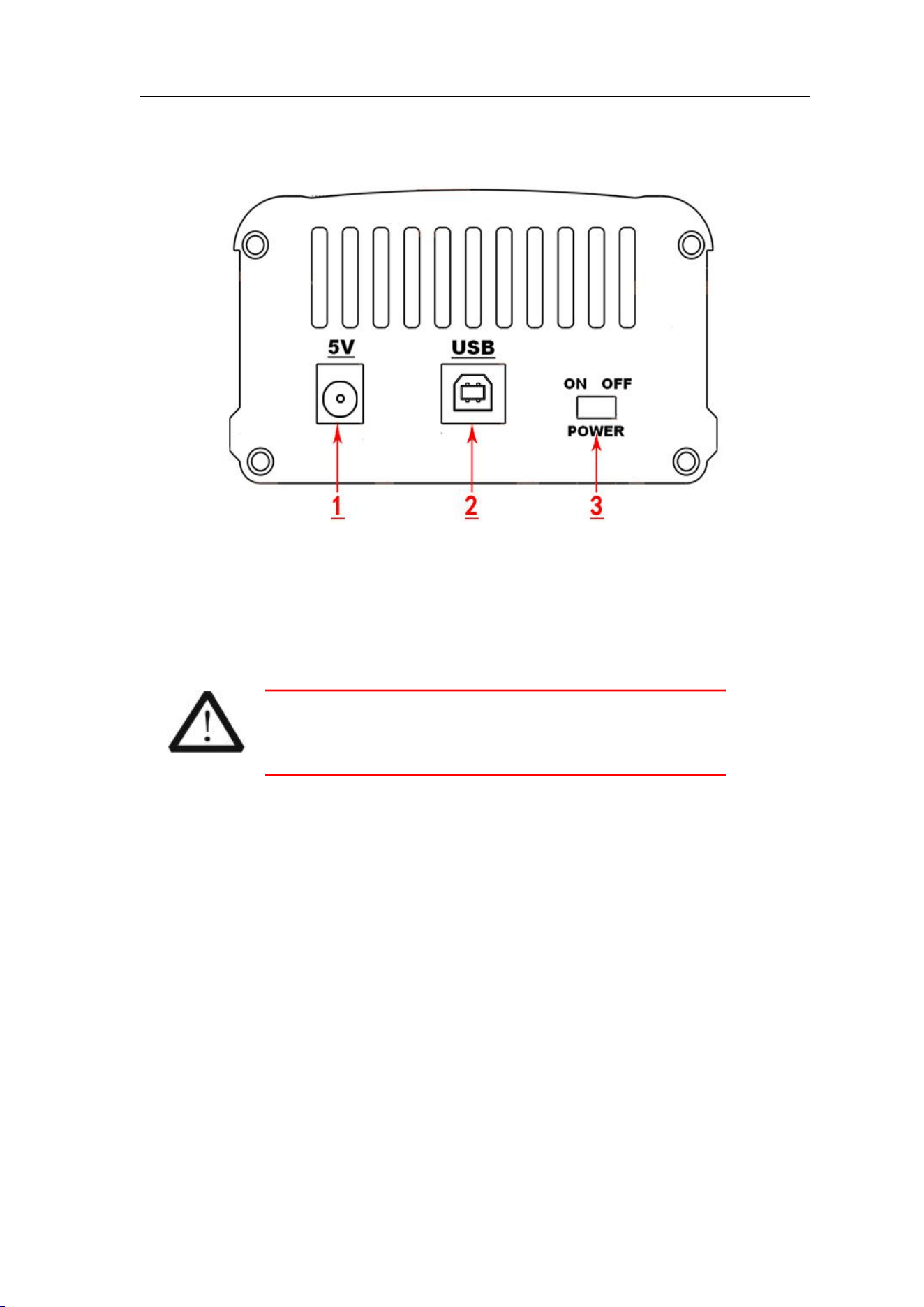
Left Panel Overview
1. DC power input connector (External diameter 5.5mm, Inner diameter 2.1mm)
The DC voltage is 5V±0.5V, and electric current is 500 mA. The
maximum power input cannot exceed 5W. Instrument also supports
DC5V mobile power supply.
Note:
Please use original power adapter and data cable to
guarantee normal use.
2. USB Device Interface
This is for communicating with PC.
— Use PC Host software to program.
3. Power Switch
Set to “ON” to turn on this instrument or “OFF” to turn it off.
FeelTech
FY2300H Series User’s Manual 9
Power On and Inspection
Connect to Power
Please connect the generator to AC power supply using the Power Adaptor
supplied in the accessories. The specifications of the adaptor: DC voltage is
5V±0.5V, and electric current should be no lower than 800 mA. The power of this
instrument is less than 5W.
Power On
Turn on the power switch after the power cord is connected. The generator
will execute self-inspection. The LCD will show welcome interface after the
inspection is over. If the generator cannot work normally, please check the
Chapter “Troubleshooting” for solution.
Set the System Language
FY2300H series Function/Arbitrary Waveform Generator supports Chinese
and English system languages. You can press SYS→CONF to switch the system
language.
FeelTech
10 FY2300H Series User’s Manual
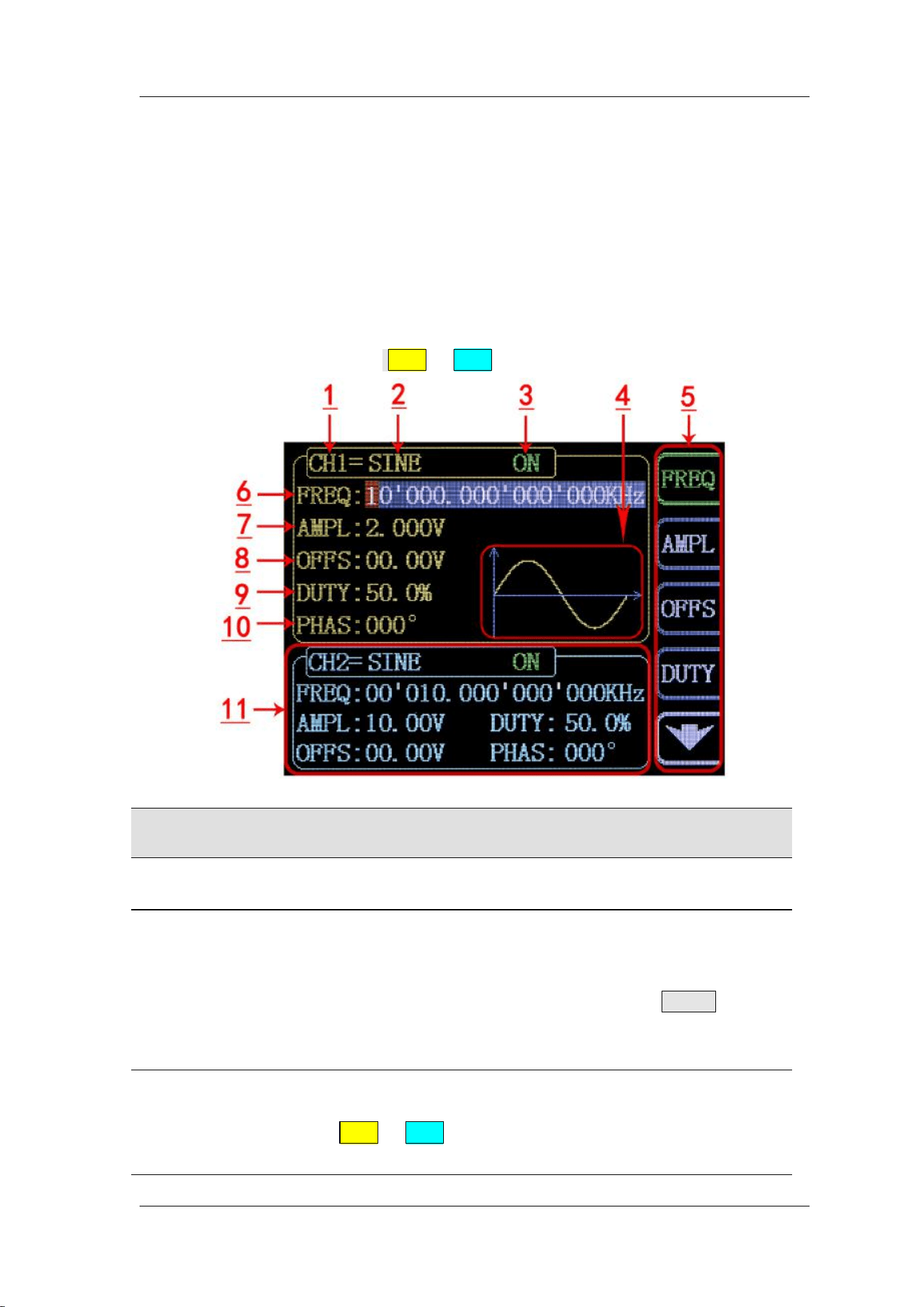
User Interface
The user interface of FY2300H provides four types of display modes: Dual
Channels Parameters (default), Single Channel Extension, Auxiliary Functions
and System Interface.
Dual Channels Parameters (default)
The upper half of LCD displays the channel selected currently and the
parameters can be set. Press CH1 or CH2 to change current channel selected.
Item
Description
1
Current channel selected.
Display current channel selected for operation.
2
Current waveform selected.
Display the name of current waveform selected. For example,
“CH1=Sine” means current waveform selected of CH1 is
Sine Wave. It can be changed by press WAVE button.
Meanwhile, waveform can be changed quickly by rotating
ADJ Knob when waveform switch function is activated.
3
Output status of current channel.
Display On/Off status of current channel. It can be switched
by Press CH1 or CH2.

FeelTech
FY2300H Series User’s Manual 11
4
Waveform
Display diagram of current waveform
(
Including Arbitrary
)。
5
Manu Bar
Display current operable options 。
6
Frequency
Display frequency value of current channel. Press FREQ
button to highlight it and use ADJ Knob and Arrows to change
the value.
7
Amplitude
Display amplitude value of current channel. Press AMPL
button to highlight it and use ADJ Knob and Arrows to change
the value.
8
Offset
Display DC Offset value of current channel. Press OFFS
button to highlight it and use ADJ Knob and Arrows to change
the value.
9
Duty Cycle
Display Duty Cycle value of current channel. Press DUTY
button to highlight it and use ADJ Knob and Arrows to change
the value.
10
Phase
Display Phase value of current channel. Press
▼
button
to enter Single Channel Extension and press PHAS to
highlight it and use ADJ Knob and Arrows to change the
value.
11
Parameters of the channel unselected.
Display parameters of the channel unselected including
frequency, amplitude, offset, phase, duty cycle and output
status. These Parameters cannot be changed directly in this
interface. If you need to change them, Please switch the
channel to be selected.
FeelTech
12 FY2300H Series User’s Manual
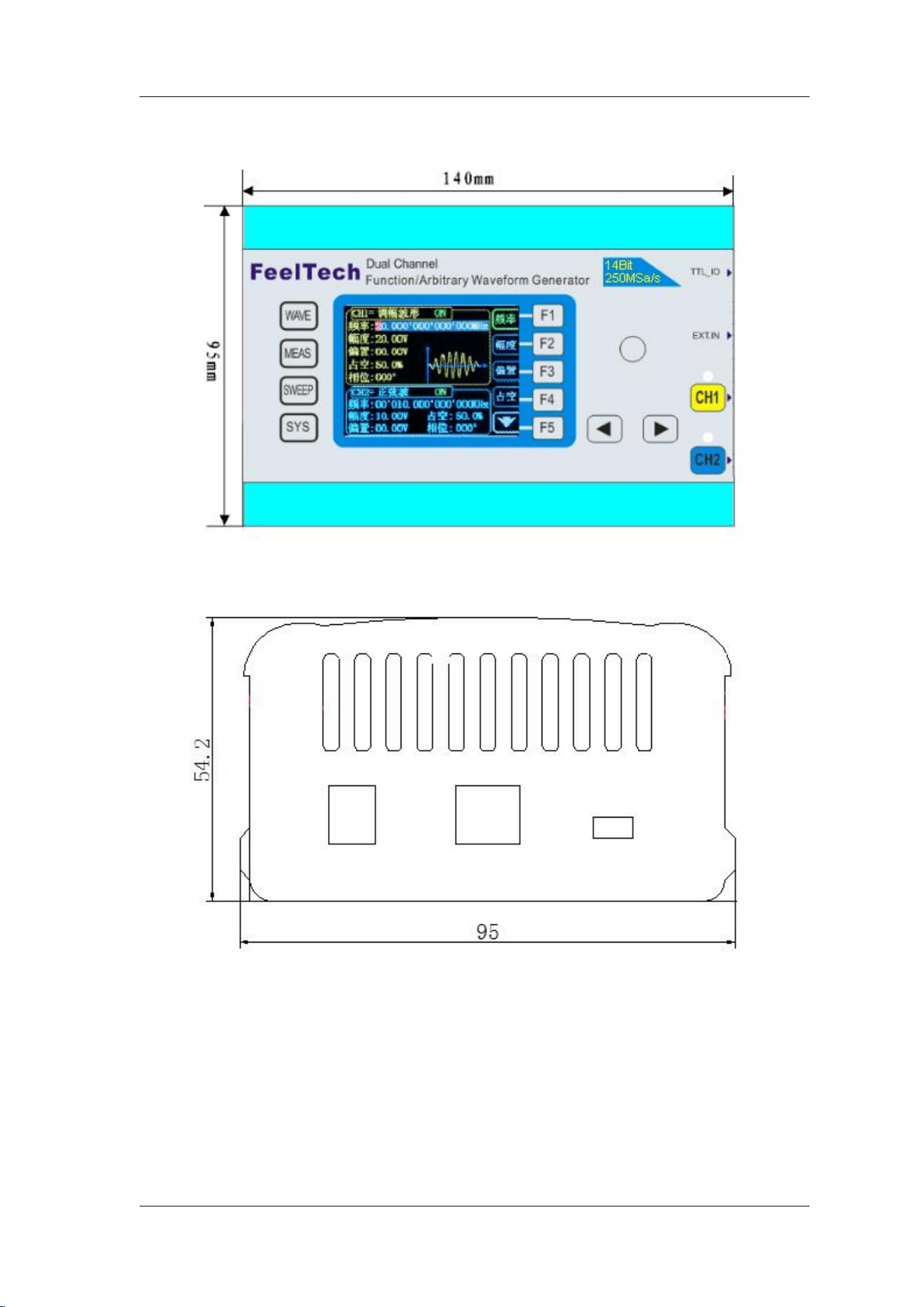
Appearance and Dimensions
Front View
Left View
FeelTech
FY2300H Series User’s Manual 13
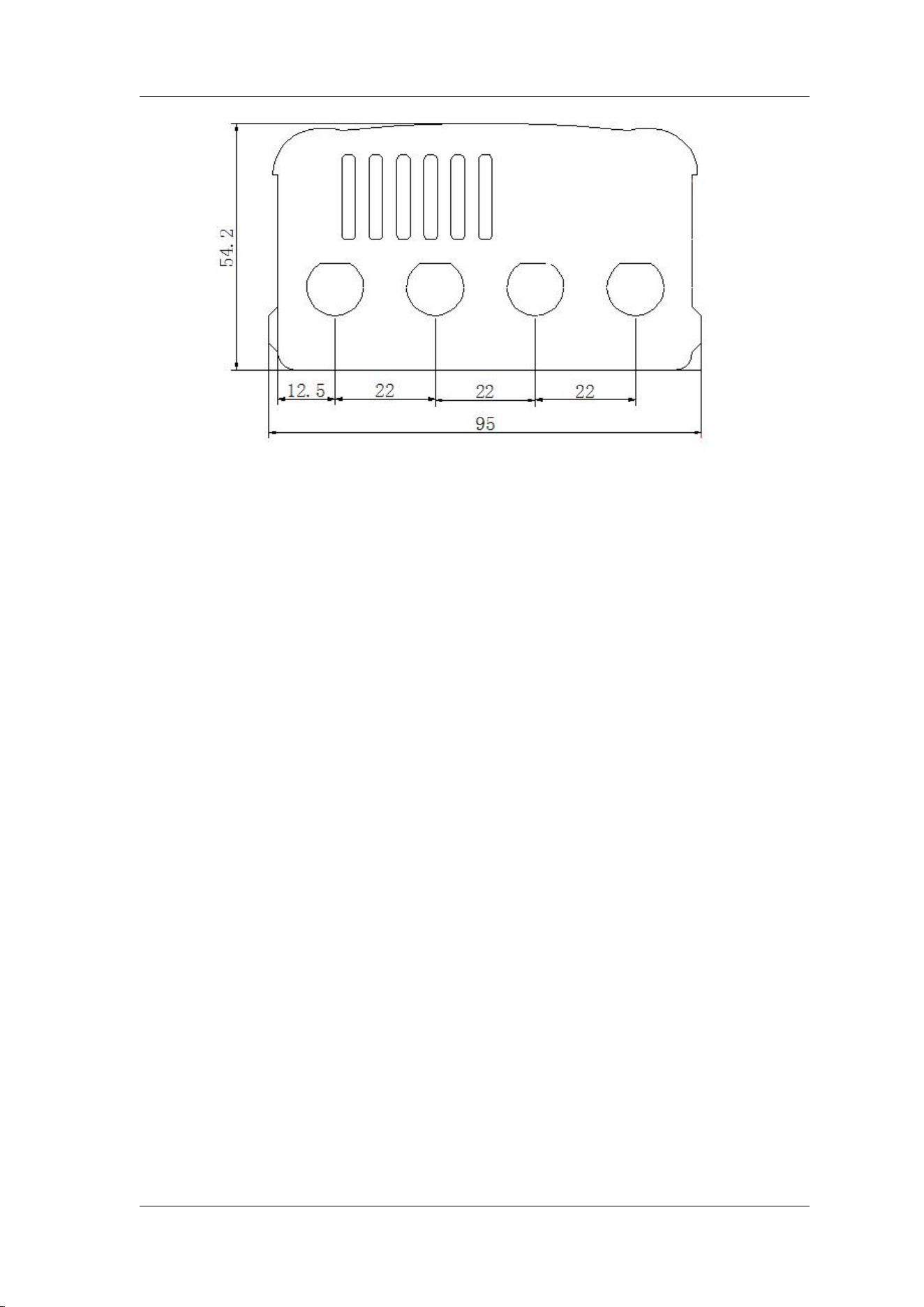
Right View

FeelTech
14 FY2300H Series User’s Manual
Front Panel Operations
Waveform Output
FY2300H series can output waveforms (Sine, Square, Triangle/Ramp, Pulse
and Noise etc.) from one of the channels separately or from the two channels at
the same time. At start-up, the dual channels are configured to output a sine
waveform with 10kHz frequency and 5Vpp amplitude by default. Users can
configure the instrument to output various waveforms.
Select Output Channel
CH1 and CH2 buttons are used to change current channel selected. At
start-up, CH1 is displayed on the top with yellow color and CH2 is displayed on
the bottom with blue color. Press CH1 or CH2 to select channel needed. When
selecting CH2 as output channel, CH2 parameters displays on the top for
configuration.
KEY POINT:
CH1 and CH2 can not be selected at the same time. Users can first select
CH1 and then select CH2 after configuring the waveform and parameters of
CH1. If you need to change the parameters of two channel at same time,
please refer to Chapter “Synchronization”.

FeelTech
FY2300H Series User’s Manual 15
Select Waveform
FY2300H can output Function/Arbitrary Waveform including:
Sine
Square
Triangle/Ramp
Rise Sawtooth
Fall Sawtooth
Lorenz Pulse
Multitone
Noise
Electrocardiogram (ECG)
Trapezoidal Pulse
Sinc Pulse
Narrow Pulse
Gauss White Noise
Step Triangle
Positive Step
Inverse Step
Positive Exponent
Inverse Exponent
Positive Falling Exponent
Inverse Falling Exponent
Positive Logarithm
Inverse Logarithm
Positive Falling Logarithm
Inverse Falling Logarithm
Linear FM
AM
FM
Positive Half Wave
Negative Half Wave
Positive Half Wave
Rectification
Negative Half Wave
Rectification
User-defined waveform
Press WAVE to change waveform selected. Or rotate ADJ Knob under waveform
switching status to change waveform. The waveform diagram displays on the
screen. At start-up Sine is selected by default. (Users can also configure start-up
waveform. Please check Chapter “Save and Load”.
Waveforms
Sine
Square
Triangle
Sawtooth
Arbitrary
Function Name
SINE
SQUR
TRGL
Ramp
Arb
Parameters
Frequency
√
√
√
√
√
Amplitude
√
√
√
√
√
Offset
√
√
√
√
√
Phase
√
√
√
√
√
Duty Cycle
√
Note: Arbitrary waveforms can be edited and downloaded from PC software
provided by FeelTech. The relevant software and driver can be downloaded from
our website: www.feeltech.net .
FeelTech
16 FY2300H Series User’s Manual
Set Frequency
Frequency is one of the most important parameters of waveforms. For
different instrument models and waveforms, the setting ranges of frequency are
different. For detailed information, please refer to “Frequency” in
“Specifications”. The default frequency is 10kHz.
Press FREQ button to highlight value of Frequency. Then use Arrow
buttons and ADJ Knob to set the value. Press Arrows button to move the cursor
and rotate ADJ Knob to set the value.
Under setting frequency status, press ADJ Knob to change frequency units
among MHz, KHz, Hz, mHz, μHz.

FeelTech
FY2300H Series User’s Manual 17
Set Amplitude
The amplitude setting range is limited by the “Attenuation” and “Frequency”
settings. Please refer to “Output Characteristics” in “Specifications”. The
default value is 5Vpp.
Press AMPL button to highlight amplitude value. Then use Arrows button
and ADJ Knob to set the value. Press Arrows button to move the cursor and
rotate ADJ Knob to set the value.
FeelTech
18 FY2300H Series User’s Manual
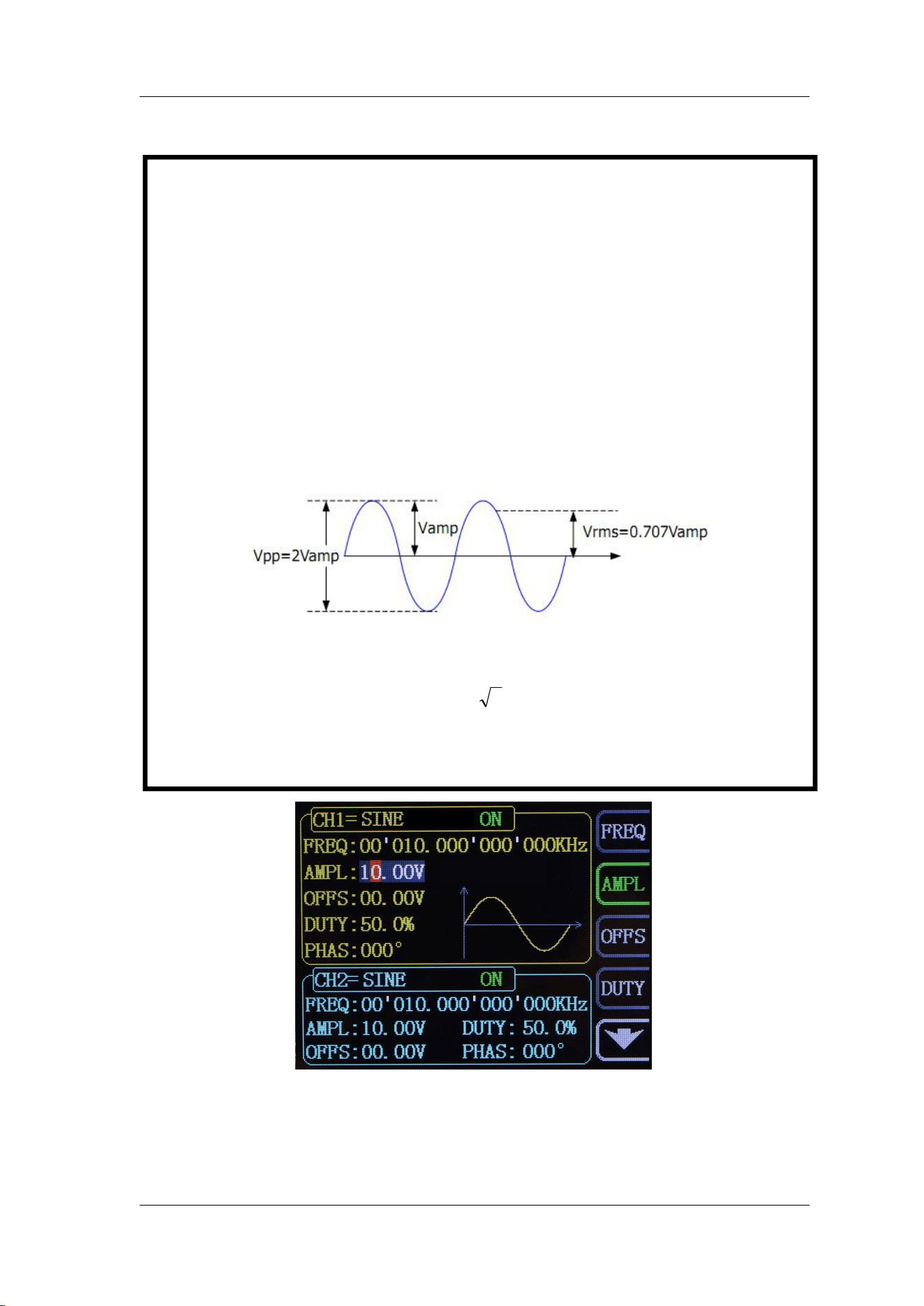
Key Points:
1.What’s the difference of amplitude in Vpp and the corresponding value in
Vrms?
Answer:
Vpp is the unit for signal peak-peak value and Vrms is the unit for signal effective value.
The default unit is Vpp.
Note:
For different waveforms, the relation between Vpp and Vrms is different. The
relation of the two units is as shown in the figure below (take sine waveform as
an example).
According to the figure above, the conversion relation between Vpp and Vrms
fulfills the following equation:
Vpp = 2
2
Vrms
For example, if the current amplitude is 5Vpp, For sine waveform, the
converted value is 1.768Vrms.
FeelTech
FY2300H Series User’s Manual 19
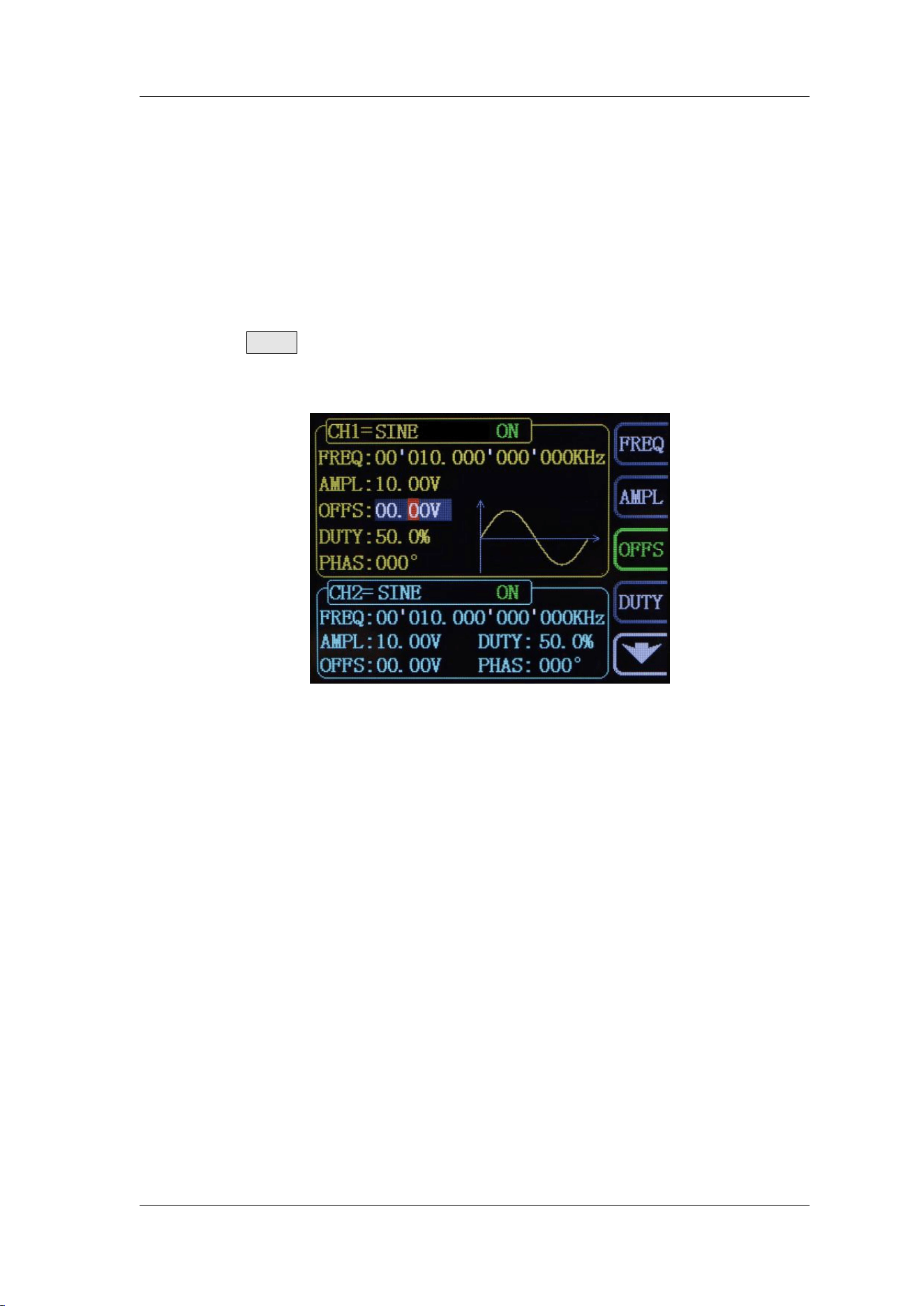
Set Offset
The DC offset setting range is limited by the “Attenuation”. Please refer to the
“Output Characteristics” in “Specifications”. The default value is 0VDC.
The DC offset voltage displayed on the screen is the default value or the
offset previously set. When the attenuation value is changed, the instrument will
set the value according to the attenuation value automatically.
Press OFFS button to highlight offset value. Then use Arrows button and
ADJ Knob to set the value. Press Arrows button to move the cursor and rotate
ADJ Knob to set the value.
FeelTech
20 FY2300H Series User’s Manual
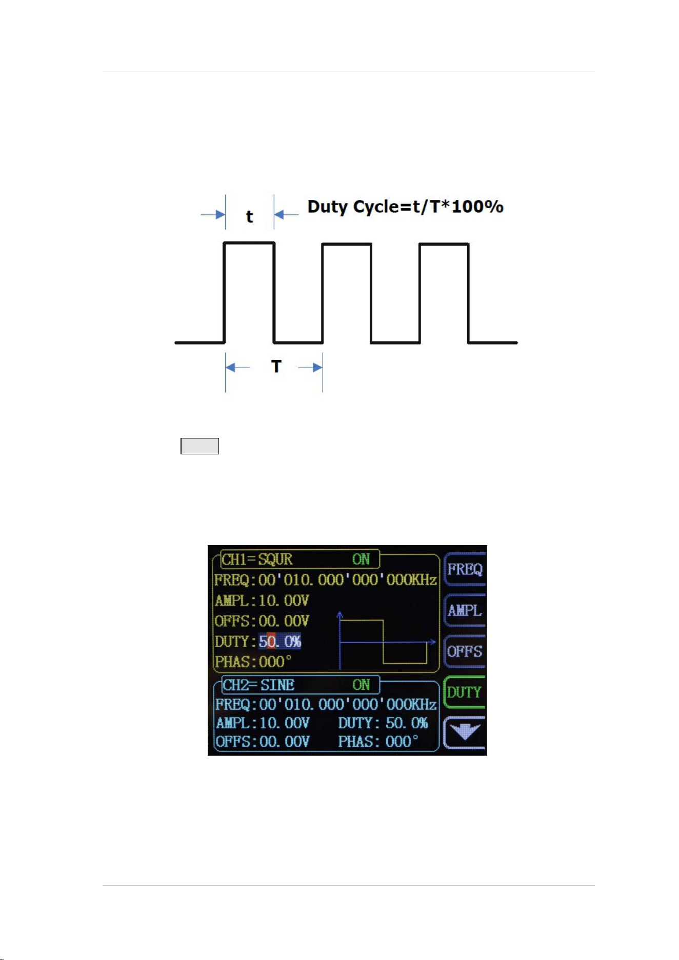
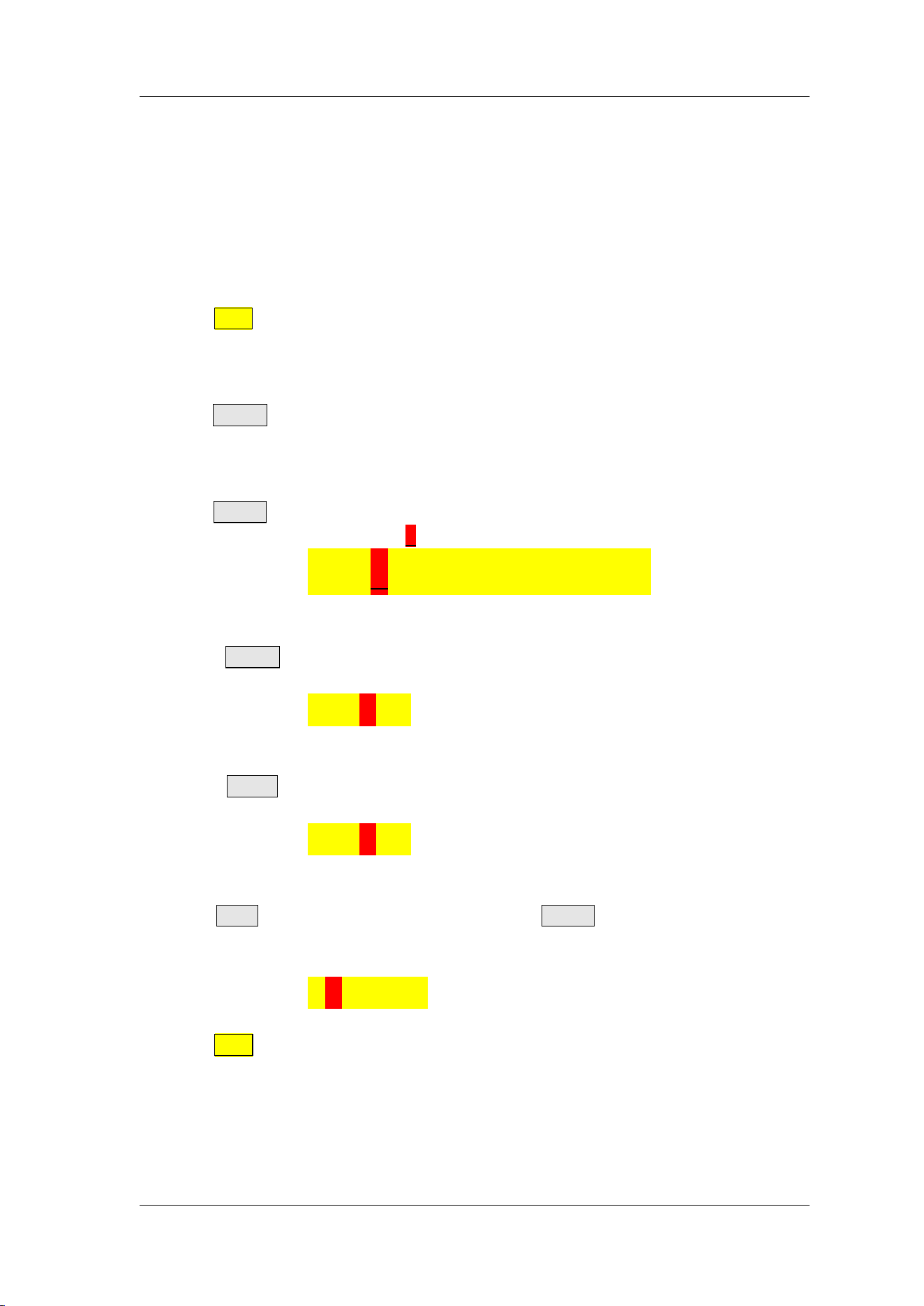
Set Duty Cycle (Square)
Duty cycle is defined as the percentage that the high level takes up in the
whole period (as shown in the figure below). This parameter is only available
when square is selected.
The setting range of duty cycle is limited by the “FREQ” setting. Please refer
to “Waveform Characteristics” in “Specifications”. The default value is 50%.
Press DUTY button to highlight duty cycle value. Then use Arrows button
and ADJ Knob to set the value. Press Arrows button to move the cursor and
rotate ADJ Knob to set the value.
The setting range of duty cycle is 0.1%-99.9%;
Press ADJ Knob under duty cycle setting status will initial the value to 50%.
FeelTech
FY2300H Series User’s Manual 21
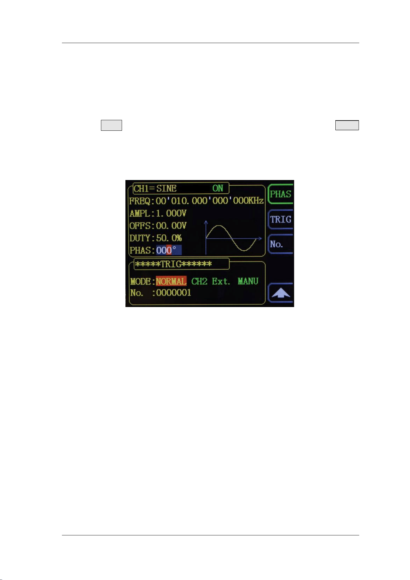
Set Phase
The setting range of phase is from 0° to 359.9°. The phase resolution is 0.1°.
The default phase value is 0°
The start phase displayed on the screen is the default value or the phase
previously set.
Press ▼ button to enter Single Channel Extension. Then press PHAS
button to highlight phase value. Then use Arrows button and ADJ Knob to set the
value. Press Arrows button to move the cursor and rotate ADJ Knob to set the
value.
FeelTech
22 FY2300H Series User’s Manual
Enable Output
After configuring the parameters of the waveform selected, waveform output
could be enabled.
At start-up output of CH1 and CH2 are both turned on as default. At this time
indicator lights of dual channels illuminate.
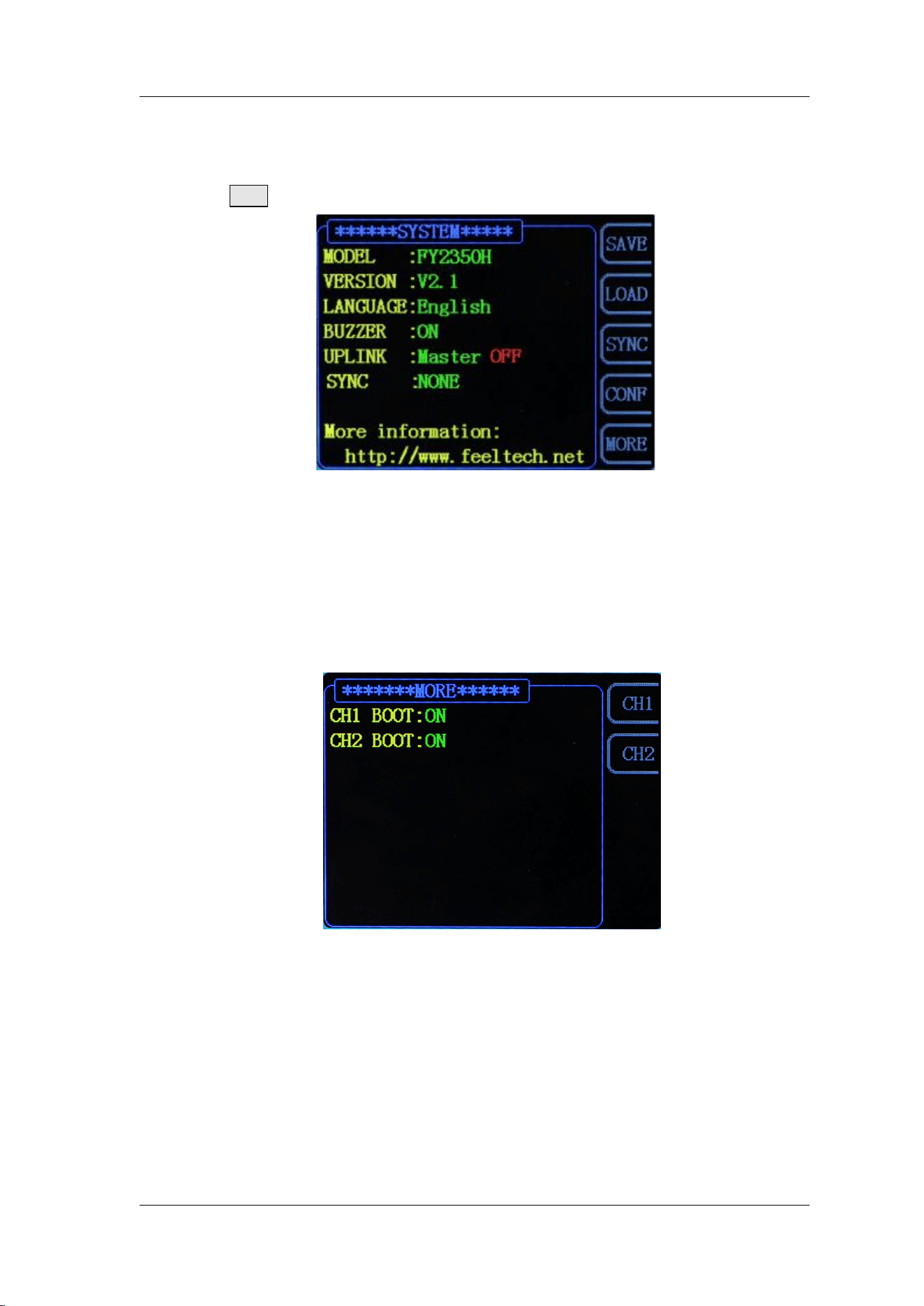
The default status can be modified. Press【SYS】button and then press【MORE】
button to set the output status of dual channels.
For CH1 there are two status:
1) Generator is in parameter setting status and current channel selected is
CH1, then press CH1 to switch between output ON/OFF.
2) Generator is in other working status or current channel selected is not
CH1, then press CH1 to make CH1 as channel selected and press CH1
again to switch between output ON/OFF.
For CH2 there are two status:
3) Generator is in parameter setting status and current channel selected is
CH2, then press CH2 to switch between output ON/OFF.
4) Generator is in other working status or current channel selected is not
CH2, then press CH2 to make CH2 as channel selected and press CH2
again to switch between output ON/OFF.
FeelTech
FY2300H Series User’s Manual 23
Example:Output Sine Waveform
This section mainly introduces how to output a sine waveform (Frequency:
20kHz, Amplitude:2.5Vpp, DC Offset: 1.6VDC, Start Phase: 90.9°) from the [CH1]
channel.
1. Select output channel
Press CH1 to select CH1. Now all characters and border of the channel is
displayed in yellow.
2. Select the Sine
Press WAVE button to select Sine. Then the diagram of Sine displays on the
screen.
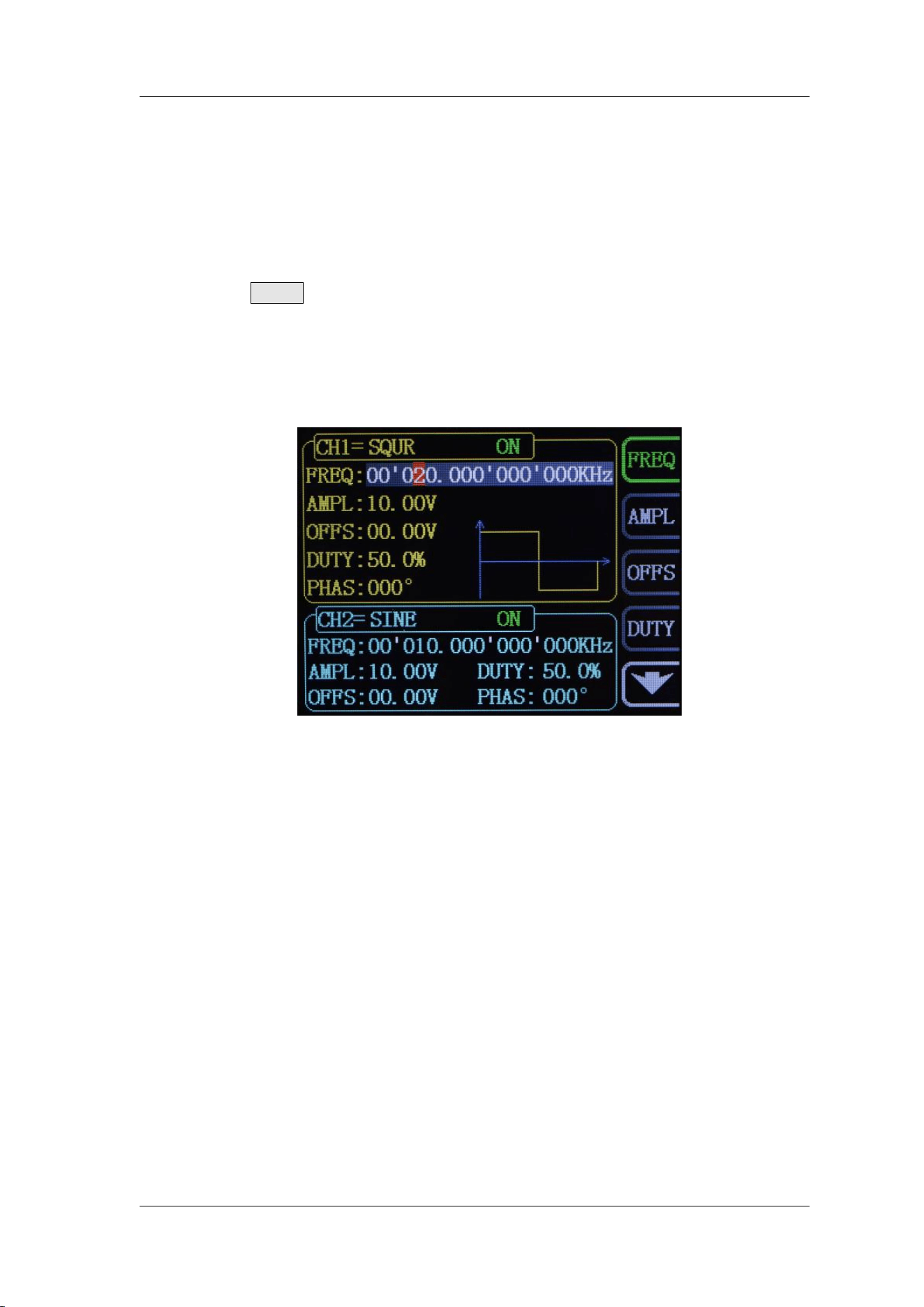
3. Set the frequency
Press FREQ button to highlight the frequency value. Press Arrow buttons to
move the cursor to the position “2” below. Then rotate the ADJ Knob to get “2”.
FREQ:00’020.000’000’000kHz
4. Set the Amplitude
Press AMPL to highlight the amplitude value. Press Arrow buttons to move
the cursor and rotate the ADJ Knob to get the figures below.
AMPL:02.50V
5. Set Offset
Press OFFS to highlight the offset value. Press Arrow buttons to move the
cursor and rotate the ADJ Knob to get the figures below.
OFFS:01.60V
6. Set Phase
Press ▼ button to page down and press PHAS button to highlight phase
value. Then Press Arrow buttons to move the cursor and rotate the ADJ Knob to
get the figures below.
PHAS:090.9°
7. Enable the output
Press CH1 button to turn CH1 output on. The [CH1] connector outputs the
configured waveform.
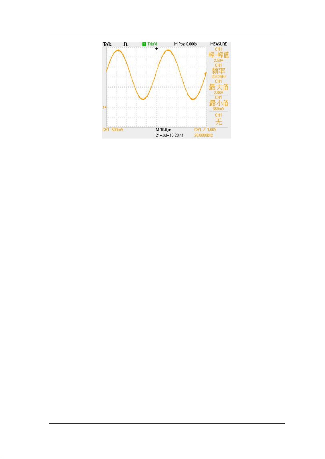
8. Observe the output waveform
Connect the [CH1] connector to the oscilloscope with BNC cable. The
waveform is as shown below.
FeelTech
24 FY2300H Series User’s Manual
FeelTech
FY2300H Series User’s Manual 25
Generate a Burst Waveform
This instrument can output a burst (waveform with specified number of cycles)
using standard waveforms such as sine, square, Triangle/ramp, and noise, or
arbitrary waveforms. The instrument supports control of burst output by internal
CH2, manual and external trigger source.
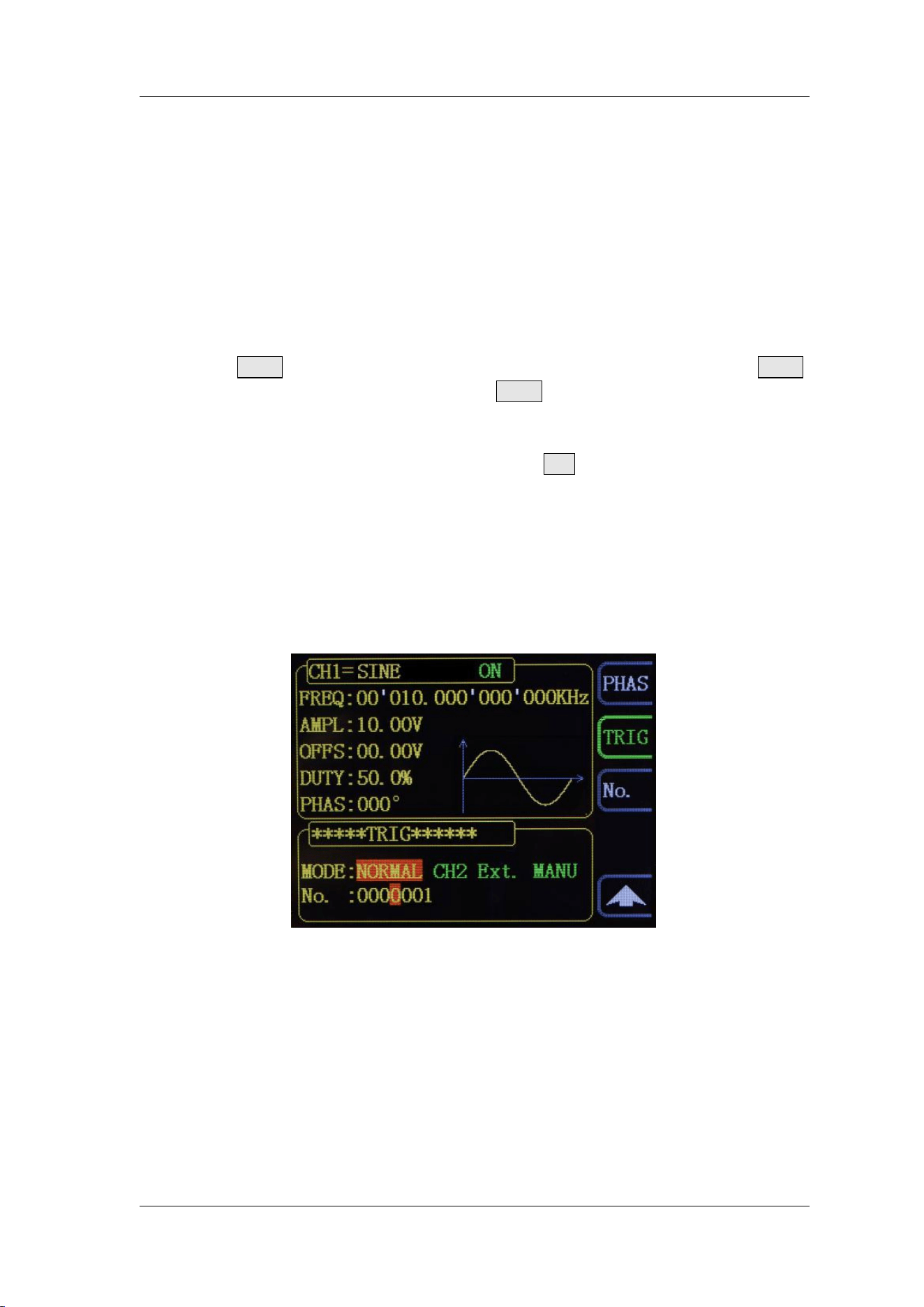
Enable Burst Function
Press ▼ button in CH1 parameter setting status. Then press “TRIG”
button to enter burst function. Then press TRIG button to select trigger sources
from “ CH2”, “Ext.” and “MANU”. Then the generator will output burst waveform
according to current configuration.
When the burst function is enabled, press No. button to set the cycles of
burst. Use arrow buttons and ADJ Knob to set the numbers from 1 to 1048575.
NORMAL: The Burst function is disabled。
CH2 Trigger: CH1 will generate a burst when CH2 generates a pulse.
Ext. Trigger: CH1 will generate a burst when EXT.IN connector was inputted a
pulse.
MANU Trigger: User can trigger a burst by pressing ADJ Knob (OK button).
FeelTech
26 FY2300H Series User’s Manual
Frequency Meter/Counter
FY2300H provides a counter which can measure various parameters of
external input signal such as frequency, period, duty cycle, positive pulse width
and negative pulse width. Dual channels output can work together with counter.
Enable the Counter
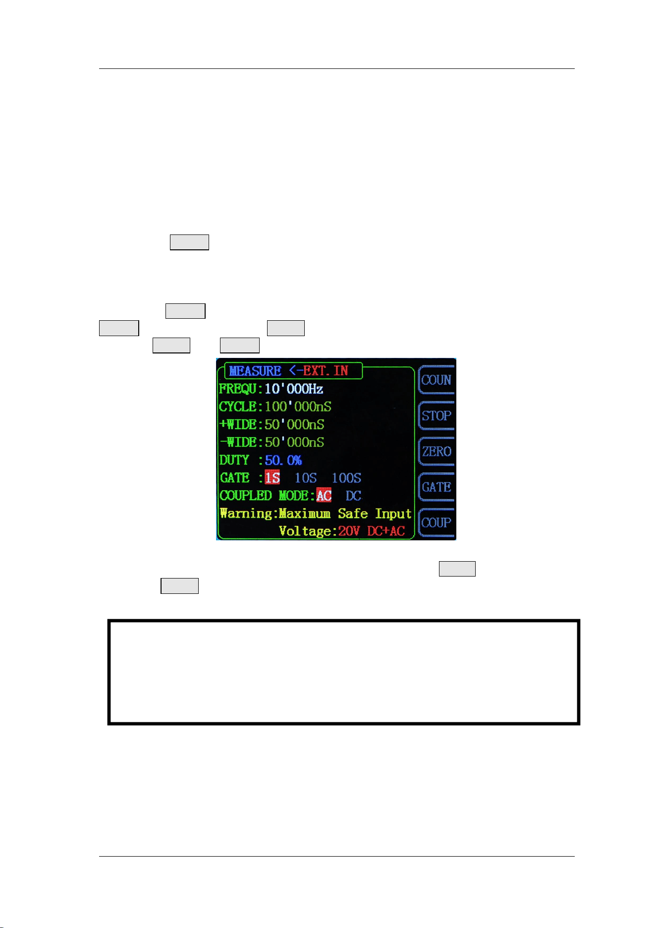
Press MEAS button of the front panel to enable the counter and
measurement Manu. External signal for measurement can be inputted by EXT.IN
connector and the result will be displayed on the screen in real time. The lowest
frequency workable is 0.01 Hz. (GATE TIME:100S)。
Press COUN button to enter external pulse counter function. At this time
COUN button is turned into FREQ button. Repeat pressing this button to switch
between FREQ and COUN.
Frequency Meter/Counter Interface
When the Frequency Meter/Counter is turned on, press STOP button to pause
and press ZERO button to reset.
Key Point:
Amplitude of signal inputted should be bigger than 1.5V. Maximum safe
voltage inputted from EXT.IN is 20V. Maximum safe voltage inputted from
TTL_IO is DC5V. The Uplink function need to be turned off when using
Counter/Meter.

FeelTech
FY2300H Series User’s Manual 27
Set the Counter
Gate Time
Press GATE button to select gate time. The default is “1S”. It’s better to use
“10S” as gate time for low frequency signal.
Gate Time
Frequency Resolution
1S
1Hz
10S
0.1Hz
100S
0.01Hz
Coupling
Set the coupling mode of the input signal to “AC” or “DC” and the default is
“AC”.
When the AC coupling mode is selected, signal should be inputted from EXT.IN
terminal.
When the DC coupling mode is selected, signal should be inputted from TTL_IO
terminal.
FeelTech
28 FY2300H Series User’s Manual
Sweep
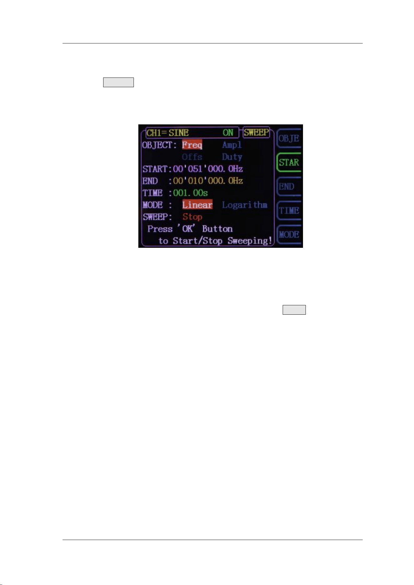
Press SWEEP button of front panel to enable sweep function. FY2300H can
output sweep from CH1. In sweep mode, the generator outputs signal variably
from the start frequency to stop frequency within the specified sweep time. It can
generate sweep output for Sine, Square, Triangle/Ramp and arbitrary waveform.
Sweep Object
FY2300H Can output sweep from CH1. The sweep objects include frequency,
amplitude, offset, duty cycle. It can be selected by pressing OBJE button.
In Frequency Sweep Mode, the generator will output signal variably from
start frequency to end frequency within the specified sweep time.
In Amplitude Sweep Mode, the generator will output signal variably from
start amplitude to end amplitude within the specified sweep time.
In Offset Sweep Mode, the generator will output signal variably from start
offset to end offset within the specified sweep time.
In Duty Cycle Sweep Mode, the generator will output signal variably from
start duty cycle to end duty cycle within the specified sweep time.
FeelTech
FY2300H Series User’s Manual 29
Sweep Start Position
When Sweep function is enabled. Sweep start position need to be set
according to sweep objects.
Frequency Sweep: Press STAR button to highlight start frequency
parameter. Press the Arrow buttons and rotate the ADJ Knob to set the
specified value. For example:
START:00’010.000’000’000kHz
Amplitude Sweep: Press STAR button to highlight start amplitude parameter.
Press the Arrow buttons and rotate the ADJ Knob to set the specified value.
For example:
START:10.00V
Offset Sweep: Press STAR button to highlight start offset parameter. Press
the Arrow buttons and rotate the ADJ Knob to set the specified value. For
example:
START:00.00V
Duty Cycle Sweep: Press STAR button to highlight start duty cycle
parameter. Press the Arrow buttons and rotate the ADJ Knob to set the
specified value. For example:
START:50.0%
FeelTech
30 FY2300H Series User’s Manual
Sweep End Position
When Sweep function is enabled. Sweep end position need to be set
according to sweep objects.
Frequency Sweep: Press END button to highlight end frequency parameter.
Press the Arrow buttons and rotate the ADJ Knob to set the specified value.
For example:
END:00’020.000’000’000kHz
Amplitude Sweep: Press END button to highlight end amplitude parameter.
Press the Arrow buttons and rotate the ADJ Knob to set the specified value.
For example:
END:20.00V
Offset Sweep: Press END button to highlight end offset parameter. Press
the Arrow buttons and rotate the ADJ Knob to set the specified value. For
example:
END:10.00V
Duty Cycle Sweep: Press END button to highlight end duty cycle parameter.
Press the Arrow buttons and rotate the ADJ Knob to set the specified value.
For example:
END:80.0%

FeelTech
FY2300H Series User’s Manual 31
Sweep Time
When Sweep function is enabled, press TIME button to highlight time parameter.
Press the Arrow buttons and rotate the ADJ Knob to set the specified value. The
default is “1S”. The work range is 10mS~999.99S. For Example:
TIME:999.99S

FeelTech
32 FY2300H Series User’s Manual
Sweep Type
FY2300H provides Linear, Logarithm sweep types. The default is Linear
sweep. The sweep type can be switched by pressing “MODE” button.
Linear Sweep
In linear sweep type, the signal parameter varies linearly. For example, in the
frequency sweep the output frequency of the instrument varies linearly in the way
of “Changing several Hertz per second”. The variation is controlled by “Start
Frequency”, “End Frequency” and “Sweep Time”.
The step value of linear sweep object is computed by the generator, the
formula is as follows:
Step value=(End value — Start value)/(Sweep time*100)
Logarithm Sweep
In linear sweep type, the signal parameter varies logarithmically.
For example, in the frequency sweep the output frequency changes in the way of
“octave per second” or “decade per second”. The variation is controlled by “Start
Frequency”, “End Frequency” and “Sweep Time”.
When Logarithm Sweep is enabled, users can set the following parameters:
Start Frequency (F
start
), Stop Frequency (F
end
) and Sweep Time (T
sweep
).
The function prototype of Logarithm Sweep:
F
current
=P
T
F
current
is the instantaneous frequency of the current output. P and T could be
expressed as shown below by the above-mentioned parameters:
P=10
lg(F
stop
/F
end
)/T
sweep
T=t+lg(F
start
)/lg(P)
Wherein, t is the time from the start of the sweep and its range is from 0 to
T
sweep.

FeelTech
FY2300H Series User’s Manual 33
Enable Sweep Function
Press SWEEP button of front panel to enable sweep function. Then press
ADJ Knob to start sweep process. Press ADJ Knob again to stop sweep.
Start value and End value
Start value and stop value are the upper and lower limits of sweep for
specified parameter. sweep. The generator always sweeps from the start value to
the end value and then returns back to the start value and continues indefinitely.
For example, in Frequency Sweep function:
Start Frequency < End Frequency: the generator sweeps from low
frequency to high frequency.
Start Frequency > End Frequency: the generator sweeps from high
frequency to low frequency.
Start Frequency = Stop Frequency: the generator outputs with a fixed
frequency.
When Sweep function is enabled, press STAR button to highlight start value. Use
arrow buttons and ADJ Knob to set the specified value. Different frequency sweep
corresponds to different start frequency and end frequency range.
Sine: 100mHz to 25MHz~60MHZ (Varies according to different model)
Square: 100mHz to 25MHz
Ramp: 100mHz to 10MHz
Arbitrary:100mHz to 10MHz
The generator will restart sweep (according to the current new configuration)
from the specified “start frequency” after start or end frequency is changed.
FeelTech
34 FY2300H Series User’s Manual
System Configuration and Auxiliary Functions
Press SYS button of front panel to enter System interface.
SAVE: To save current parameters of waveform to save positions (20 sets).
LOAD: To load parameters to current working status from save positions.
SYNC: To synchronize CH2 parameter with CH1. Each parameter can be
selected separately for synchronization including waveform,
frequency, amplitude, offset and duty cycle.
CONF: To set system language, turn on/off Buzzer and Uplink mode.
MORE: To set default output status of dual channels.

FeelTech
FY2300H Series User’s Manual 35
Save and Load
Press SAVE button in System interface to save parameters of current
waveform to specified position. Press “Load” button to load parameters of
waveforms previously set to current system status.
Select S xx on the right to save current parameters to corresponding
position.
Select L xx on the right to load parameters from corresponding position to
current system status.
FY2300H provides 20 positions for saving.
The generator will load default parameters from Position 1
automatically after start-up.

FeelTech
36 FY2300H Series User’s Manual
Synchronization
Press SYNC button in system interface to enter synchronization setting
interface. Press corresponding buttons on the right to highlight or cancel selecting
status to set synchronization status of CH2.
When the synchronization of corresponding parameters are activated, the
corresponding parameters of CH2 will vary according to variation of CH1
automatically. The parameters workable for synchronization include waveform,
frequency, amplitude, offset, and duty cycle, which can be set separately.
When WAVE is highlighted, the waveform of CH2 will vary according to
variation of CH1.
When FREQ is highlighted, the frequency of CH2 will vary according to
variation of CH1.
When AMPL is highlighted, the amplitude of CH2 will vary according to
variation of CH1.
When OFFS is highlighted, the offset of CH2 will vary according to variation
of CH1.
When DUTY is highlighted, the duty cycle of CH2 will vary according to
variation of CH1.
FeelTech
FY2300H Series User’s Manual 37
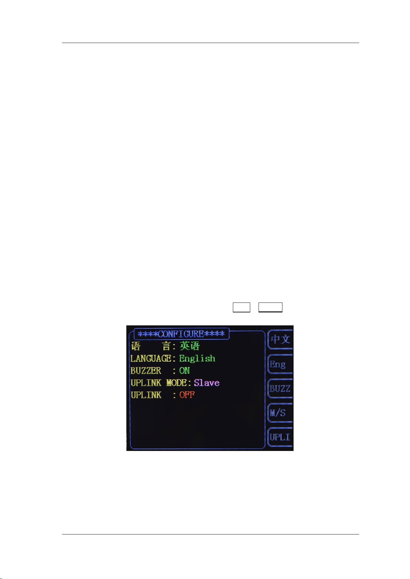
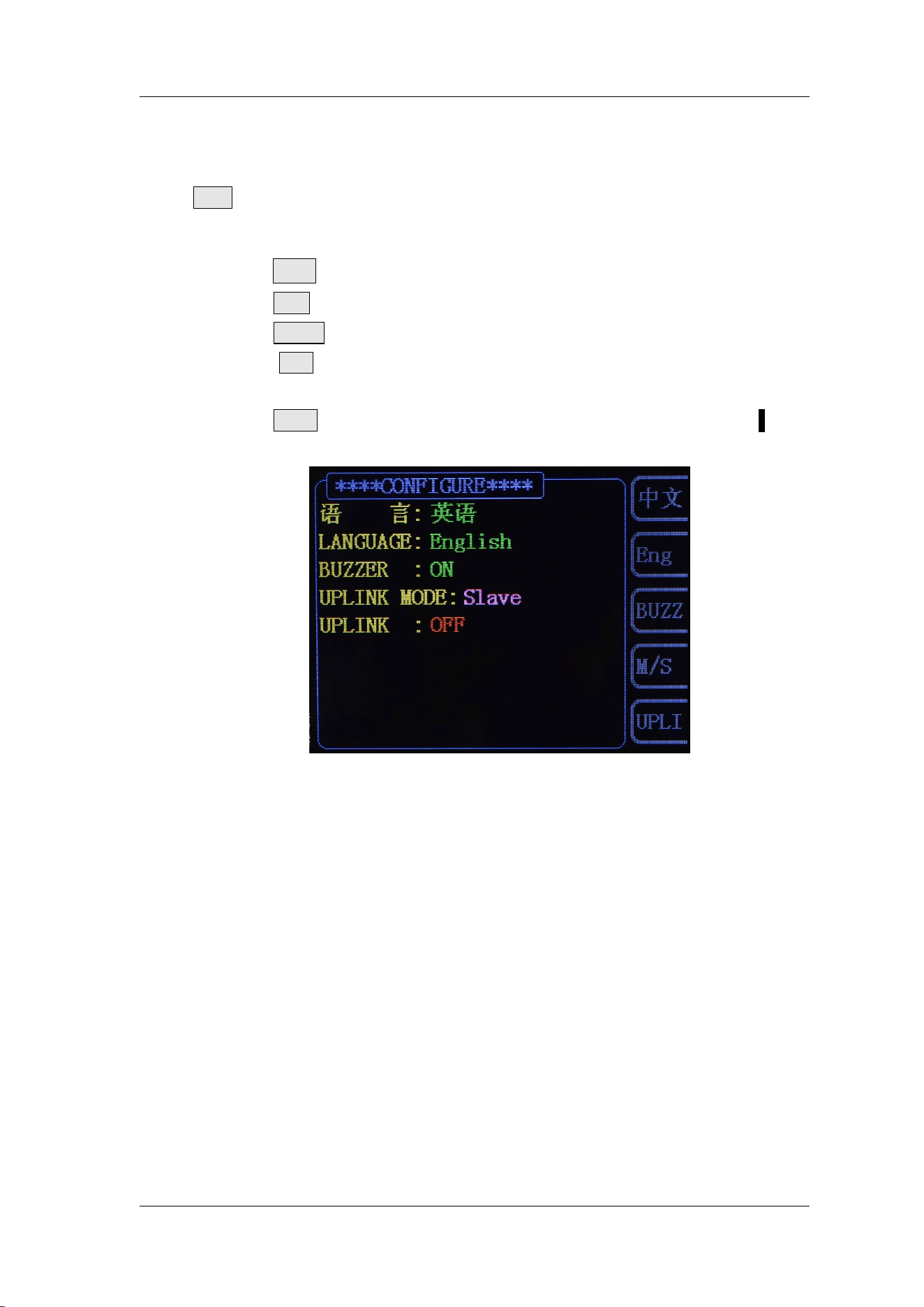
Configuration
Press SYS button to enter system interface. Then press “CONF” button to enter
system configuration interface. Press corresponding buttons to select system
work mode.
Press
中文
button to select Chinese as system language.
Press Eng button to select English as system language.
Press BUZZ button to turn on/off buzzer. On is the default.
Press M/S button to set uplink mode: Master/Slave. Master is the
default.
Press UPLI button to turn on/off uplink function. Off is the default.

FeelTech
38 FY2300H Series User’s Manual
Uplink
FY2300H supports multi-machine uplink, which can provide users more
channels for output. In uplink network, only one master machine can exist. Others
must be set as slave machine. The setting method is as follows:
Select on FY2300H as master machine. Press SYS -> CONF ->M/S, to set
the UPLINK MODE to be “Master”. Press UPLI, to set the UPLINK to be
“ON”.
Set all other machines to be slave machines. Press SYS -> CONF ->M/S, to
set the UPLINK MODE to be “Slave”. Press UPLI, to set the UPLINK to be
“ON”. Repeat this step to set all slave machines.
Connect all FY2300H in parallel by TTL_IO connecter.
The uplink machines cannot exceed 8 because the driving ability.
When the setting above has been finished, all machines in network will work
synchronously according to the start phase of master machine. When outputting
signal with same frequency, multi channels output can be executed with phase
adjustable.
FeelTech
FY2300H Series User’s Manual 39
Troubleshooting
This chapter lists the commonly encountered failures of FY2300H and their
solutions. When you encounter these problems, please solve them following the
corresponding steps below. If the problem remains still, please contact FeelTech
and provide the device information (Press SYS to get it).
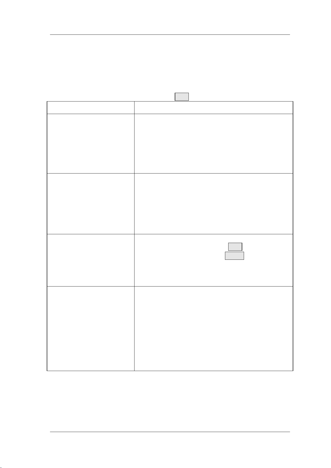
Failure Phenomena
Solutions
The screen of the
generator is still dark (no
display) after switch on.
1) Check whether the power is correctly connected.
2) Check whether the power switch has been pulled
in place.
3) Restart the instrument after finishing the above
inspections.
4) If it still does not work correctly, please contact
FeelTech.
. The screen of the
generator is still dark (no
display) after switch on, but
the channel indicator lights
illuminate.
This is because the power supply is not enough.
1). Please use original power adapter.
2). Please use original data cable.
3). Please do not repeat switching the power switch
too soon. The instrument has power protection.
Please wait for 2S at least to switch on after it is
switched off.
CH2 is locked.
1) Check whether the generator is worked in
synchronization mode. Press SYS button to enter
system interface, then press SYNC button to enter
synchronization setting interface and cancel all
parameters selected.
2) If the problem is still, please restart the generator.
The settings are correct but
there’s no waveform being
generated:
1) Check whether the BNC cable is connected
tightly with CH1 or CH2 connector.
2) Check whether the BNC cable has internal
damage.
3) Check whether the BNC cable is connected
tightly with the test instrument.
4) Check whether the indicators of CH1 or CH2 is
turned on. If not press corresponding button to turn
it on.
5) If the problem is still, please contact FeelTech.

FeelTech
40 FY2300H Series User’s Manual
Technical Specification
Unless specified, all specifications can be guaranteed if the following two
conditions are met.
The generator has passed self-inspection.
The generator has been working continuously for at least 30 minutes
under the specified temperature (18℃~28℃).
All the specifications are guaranteed unless those marked with “typical”
Frequency
FY2300H
-25MHz
FY2300H
-30MHz
FY2300H
-40MHz
FY2300H
-50MHz
FY2300H
-60MHz
Sine
0~25MHz
0~30MHz
0~40MHz
0~50MHz
0~60MHz
Square
0~25MHz
0~25MHz
0~25MHz
0~25MHz
0~25MHz
Ramp/Triangle
0~20MHz
0~20MHz
0~20MHz
0~20MHz
0~20MHz
Pulse
0~0MHz
0~20MHz
0~20MHz
0~20MHz
0~20MHz
TTL
0~25MHz
0~30MHz
0~40MHz
0~50MHz
0~60MHz
Others
0~20MHz
0~20MHz
0~20MHz
0~20MHz
0~20MHz
Resolution
1μHz (0.000001Hz)
Accuracy
± 5×10
-6
Stability
±1×10
-6
/ 3 Hours
Impedance
50Ω±10%(Typical)
Phase Range
0~359.9°
Phase Resolution
0.1°
Waveform Characteristics
Waveforms
Sine, Square, Triangle(Ramp), Arbitrary, Rise Sawtooth, Fall
Sawtooth, Lorenz Pulse, Multitone, Noise, Cardiogram, Rapezoidal
Pulse, Sinc Pulse, Narrow Pulse, Gauss White Noise, AM, FM, Step.
Waveform Length
8192Points
Sampling Rate
250MSa/s
Vertical Resolution
14 Bits
Sine
Harmonic
Suppression
≥45dBc(<1MHz);≥40dBc(1MHz~60MHz);
Total Harmonic
Distortion
<0.8% (20Hz~20kHz,0dBm)
Square
Rise/Fall Time
≤10ns (Vpp<5V)
Overshoot
≤7.5%
Duty Cycle
0.1%~99.9%

FeelTech
FY2300H Series User’s Manual 41
Sawtooth
Linearity
≥98% (0.01Hz~10kHz)
Output characteristics
Amplitude (50Ω)
<20MHz:10mVpp~20Vpp
>20MHz:10mVpp~5Vpp
Amplitude Resolution
1mV (Attenuate 20dB)
Amplitude Stability
±0.5%/ 5 Hours
Amplitude flatness
±5%(<10MHz);±10%(>10MHz);
Waveform Output
Impedance
50Ω±10%(Typical)
Protection
All channels can work more than 60 seconds when the load is
short-circuited.
Dc Offset
Offset Range
<20MHz:±10V
>20MHz: ±2.5V
Offset Resolution
1mV
TTL Output
Electrical Level
Amplitude
>3Vpp
Fan-out
>8 TTL Load
Rise/Fall Time
≤10ns
CMOS Output
Low Electric Level
<0.3V
High Electric Level
1V~10V
Rise/Fall Time
≤20ns
External Measurement
Frequency Meter
Range
0.01Hz~100MHz
Sensitivity
Gate Time 3 grades adjustable
Counter
Range
0-4294967295
Coupling
DC , AC
Working Mode
Manual
Pulse Width
measurement
Resolution 5 nS. Max. 10S
Voltage Input Range
0.7Vpp~20Vpp
Pulse Width
Measurement
Resolution 5ns,Max. Limit 10s

FeelTech
42 FY2300H Series User’s Manual
Period Measurement
Resolution 5ns,Max. Limit 10s
Sweep
Only CH1 available
Sweep Type
Linear or :Logarithm
Sweep Objects
Frequency, Amplitude, Offset, Duty Cycle
Sweep Time
0.01S~999.99S/Step
Sweep Range
Starting position and Finishing position can be set arbitrarily.
General Specifications
Display
Mode
2.4 inch TFT Color Lcd.
Save & Load
Amount
20
Position
01 to20 (01 for default value)
Interface
Type
USB to Serial interface.
Communicati
ng Speed
9600bps
Protocol
Command line mode, protocol complete open.
Power
Voltage
Range
DC5V±0.5V
Buzzer
Can be turned on/off by setting.
Environment
Temp.:0~40℃ Humidity:﹤80%
Dimension
140mm(Length)X95mm(Width)X54.2mm(Height)
Weight
Net Weight: 450g, Gross Weight: 750g

FeelTech
FY2300H Series User’s Manual 43
Appendix
Appendix A
:
Safety Notes
1. Before using this instrument, please check if the power supply is normal, to
ensure the normal use and personal safety.
2. This instrument must be used in the technical index range.
3. Please do not change the instrument circuit arbitrarily, so as to avoid damaging
equipment or endangering the safety.
Appendix B
:
Warning and personal injury
Do not apply the product in the safety protection device or emergency stop
device, or any other applications that the product failure could result in personal
injury, unless there is special purpose or use authorization. Before the installation
and use, each parameter of the technical indexes in this manual should be
referred to. If this suggestion is not obeyed, death or serious personal injury could
be caused. In this condition the company will not be responsible for any
compensation of personal injury or death, and all the company managers and
employees and auxiliary agents, distributors, other personnel concerned will be
released from any claim (including all the costs, expenses, attorney fees etc.) that
may result in.
Appendix C
:
Accessories and Options
Description
Quantity
Model
FY2300H-25M(25MHz, Dual-channel)
1
FY2300H-30M(30MHz, Dual-channel)
FY2300H-40M(40MHz, Dual-channel)
FY2300H-50M(50MHz, Dual-channel)
FY2300H-60M(60MHz, Dual-channel)
Standard
Accessories
5V 1A Power Adapter
1
USB-B Data/Power Cable
1
BNC-Clip Cable
2
BNC-BNC Cable
1
Warranty Card
1
Options
FYA2000 Series Amplifier
FPA1000 Series Amplifier
Note: Options can be ordered from local FeelTech distributors.

FeelTech
44 FY2300H Series User’s Manual
Appendix D:Warranty
FeelTech warrants that its products mainframe and accessories will be free
from defects in materials and workmanship within the warranty period. If a
product is proven to be defective within the respective period, FeelTech
guarantees the free replacement or repair of products which are approved
defective. This product enjoy 1 year warranty since its delivery. Damages caused
by misuse, vandalism, improper maintenance or force majeure are not covered by
the warranty. Any disassembly or amendment without permission will be deemed
giving up warranty rights consciously.