FeelElec
User’s Manual
FY6200 Series Fully Numerical Control
Dual Channel Function/Arbitrary
Waveform Generator
Rev2.0 April, 2019


FeelElec
FY6800 系列用户手册 I
Guaranty and Declaration
Copyright
© FeelElec Technology Co. Ltd. All Rights Reserved.
Trademark information
FeelElec is a registered trademark of Zhengzhou FeelElec Technology
Co., LTD.
Declaration
The company reserves the right to change specifications and
prices.
The information provided in this manual supersedes all previous
publications.
FeelElec shall not be liable for any errors that may be contained
in this manual, or for any incidental or consequential loss resulting from
the information and deductive functions provided in this manual, or
from the use of this manual.
No part of this manual may be reproduced or adapted without the
prior written permission of FeelElec.
Contact Us
If you have any problem or requirement when using our products or this
manual, please contact FeelElec.
Website:www.feelelec.com

Contents
Guarantee and Declaration ............................................. 错误!未定义书签。
Product Introduction ............................................................................... 3
General Description ................................................................................. 6
General Inspection .................................................................................... 6
Front Panel Overview ................................................................................ 7
Back Panel Overview ............................................................................... 10
Power On and Inspection ......................................................................... 11
User Interface ......................................................................................... 12
Dimensions ............................................................................................. 14
Front Panel Operations .......................................................................... 15
Waveform Output .................................................................................... 15
Select Output Channel .................................................................................... 15
Select Waveform ............................................................................................ 16
Selevct Frequency .......................................................................................... 17
Set Amplitude ................................................................................................ 18
Set Offset ...................................................................................................... 19
Set Duty Cycle(Square) ................................................................................... 20
Set Phase ...................................................................................................... 21
Enable Channel Output ................................................................................... 22
Example: Output sine waveform ...................................................................... 23
Generate burst waveform ............................................... 错误!未定义书签。
Digital Modulation .......................................................... 错误!未定义书签。
Frequency meter/counter ........................................................................ 30
Enable frequency meter .................................................................................. 30
Set the Counter ............................................................................................. 31
Sweep .................................................................................................... 32
Sweep Object ................................................................................................ 32
Sweep Start Position .............................................................. 错误!未定义书签。
Scan Termination Position & Sweep Time ......................................................... 34
Sweep Type ................................................................................................... 35
Enable Frequency Sweep Function ................................................................... 36
System Setup and Auxiliary Functions ....................................................... 38
Storage and Loading ...................................................................................... 39
Configuration ................................................................................................. 40
Uplink ................................................................................... 错误!未定义书签。
Synchronizing ................................................................................................ 41
Fault Handling ........................................................................................ 42
Technical Indicator ................................................................................ 43
Appendix ......................................................................... 错误!未定义书签。

FeelElec
FY6200 系列用户手册 3
Product Introduction
This manual is applicable to various models of FY6200 series Function /
Arbitrary Waveform Generator. The last three digits in the model of FY6200
instrument indicate the upper limit value of sine wave frequency (MHz) of the
instrument. For example: the “60M” of the Model Number “FY6200-60M” indicates
the Sine wave maximum output frequency is up to 60MHz.
FY6200 series dual channel function / arbitrary waveform generator is a high-
performance, cost-effective and multi-functional signal generator which integrates
the functions of function signal generator, arbitrary waveform generator, pulse
signal generator, noise generator, counter and frequency meter. The instrument
adopts large-scale FPGA integrated circuit and high-speed MCU microprocessor,
the internal circuit uses high-precision active crystal oscillator as the reference,
and the signal has high stability. Surface mount technology greatly improves the
anti-interference and service life of the instrument. The instrument has completely
independent two-way DDS signal and four-way TTL level output, which can
generate 31 preset waveform signals such as sine wave, square wave, triangle
wave, sawtooth wave, pulse wave, white noise and 64 groups of user-defined
waveforms. The instrument is easy to use, excellent technical index and perfect
combination of many functional characteristics in signal generation, waveform
scanning, parameter measurement and use, which can help users complete work
tasks faster. It is an ideal testing and measuring equipment for electronic engineers,
electronic laboratories, production lines, teaching and scientific research.
FY6200 series dual channel function / arbitrary waveform generator has
humanized keyboard layout and indication, providing users with intuitive operation
interface. The display interface adopts 3.2-inch TFT color LCD with high resolution
of 320 * 240, which can display all parameters of two channels at the same time
and prompt the current key function. The fast key greatly simplifies the complex
operation process and greatly enhances the operability of the instrument. Users
do not have to spend a lot of time to learn and familiar with the operation of the
instrument, you can use it proficiently.

The instrument has the following excellent technical indicators and
Functional Characteristics:
◆ DDS direct digital synthesis technology is used to produce accurate, stable
and low distortion output signals.
◆ It adopts the embedded panel design of ABS plastic shell, which is
convenient to integrate with user's equipment and easy to install.
◆ Use the 3.2-inch (320 * 240) color display screen is used to display the
waveform parameters of two channels at the same time.
◆ Maximum output frequency 60MHz (sine wave), 250msa / s sampling rate,
14bits vertical resolution.
◆ Long press the “OK” key during use to quickly save the current output
parameter information of the instrument, and the saved parameters can be
loaded automatically after the next power on.
◆ Fully independent dual channel output (equivalent to two independent
signal sources), which can work synchronously and the phase difference can be
precisely adjusted.
◆ Standard channel tracking function. When tracking is turned on, all
parameters of the two channels can be updated according to the user's
configuration at the same time.
◆ It can output up to 98 groups of functions / arbitrary waveforms, including
34 groups of preset waveforms and 64 groups of user-defined waveforms. Preset
waveforms include sine wave, square wave (duty cycle adjustable), triangle wave,
pulse wave (pulse width and frequency can be accurately set), rising sawtooth
wave, falling sawtooth wave, step wave, trapezoid pulse wave, cinke pulse, narrow
pulse wave, noise wave, exponential rise, exponential fall, ECG, Lorentz pulse wave,
multi audio wave, CMOS (0-10V) and DC voltage, etc.
◆ There are 64 groups of arbitrary wave storage bits, each group of storage
depth is 8192 * 14bits.
◆ High frequency accuracy: Frequency accuracy can reach 10-6 orders of
magnitude;
◆ The frequency resolution is relatively high: the full-range frequency
resolution is 1uHz(0.000001Hz);
◆ Amplitude resolution is higher: Amplitude resolution can be as low as 1mV

FeelElec
FY6200 系列用户手册 5
(0.001V).
◆ It has a DC bias function of - 10V ~ + 10V (< 20MHz), with a resolution of
1mV.
◆ With -10V~+10V DC bias function (<20MHz), resolution up to 1mV
◆ The pulse width and frequency of the pulse wave are continuously
adjustable, and the adjustment range is 20ns-1s. The pulse amplitude can be
continuously adjusted between 0-10V, and the adjustment accuracy is 0.001V.
◆ The phase adjustment range of the two channels is 0~359.99°, and the
adjustment accuracy is 0.01°
◆ No range limit: The full range of frequency is not divided into gear switches,
program-controlled settings.
◆ With digital signal output function, it can realize any CMOS level with 0~10V
amplitude.
◆ Scanning function: It can scan the four properties of the signal: frequency,
amplitude, offset, and duty cycle. It has two scanning modes: linear scan and
logarithmic scan. The scan time can reach 999.99S. The start and end of the scan
can be set arbitrarily.
◆ Burst Output Function: There has Manual Trigger, internal CH2 Trigger, and
External Trigger for your options. It can output 1~1048575 pulse trains.
◆ Various modulation types: AM, FM, PM, ASK, FSK and PSK modulations.
◆ Storage feature: it can be store 20 groups of instrument state parameters
set by users, and call up and reappear at any time.;
◆ 100M Frequency meter function: It can measure frequency, period, pulse
width and duty cycle. Max. frequency workable is 100MHz and Min. frequency
workable is 0.01 Hz.
◆ Counter Function: It has 2 coupling measure modes including DC coupling
and AC coupling. This design can solve inaccuracy problem of AC coupling.
◆ All parameters can be calibrated by internal procedures;
◆ Equipped with powerful arbitrary waveform editing function, it can edit
arbitrary waveform on PC and download to instrument output waveform.
◆ Powerful communication features that can be controlled using a PC. Open
communication protocol makes secondary development very simple
◆ High reliability: Large-scale integrated circuit, surface mount technology,
high reliability, long service life
◆ Output short-circuit protection: All signal outputs can work under load short-

circuit conditions 60S or more.
◆ Optional FYV2000 series or fpa2000 series power amplifier of our company
can stably output the undistorted power signal of more than 20W in DC-10mhz
bandwidth. The maximum output power of FPA2000-50w can reach 60W, and the
maximum output power of FPA101a can reach 100W.
General Description
General Inspection
Please follow the items below when you receive a new FY6200 series
Function/Arbitrary Waveform Generator.
1. Inspect the shipping container for damage
Keep the damaged shipping container or cushioning material until the
contents of the shipment have been checked for completeness and the
instrument has passed both electrical and mechanical tests. The consigner or
carrier shall be liable for the damage to instrument resulting from shipment.
2. Inspect the instrument
If there is mechanical damage or missing, or the instrument fails electrical and
mechanical tests, please contact your FeelElec dealer.
3. Check the accessories
Please check the accessories according to the Appendix C ( packing lists). If
the accessories are incomplete or damaged, please contact your FeelElec sales
representative.
FeelElec
FY6200 系列用户手册 7
Front Panel Overview
The front panel is divided into easy to operate functional areas. This section
briefly introduces the front panel control components and screen interface.
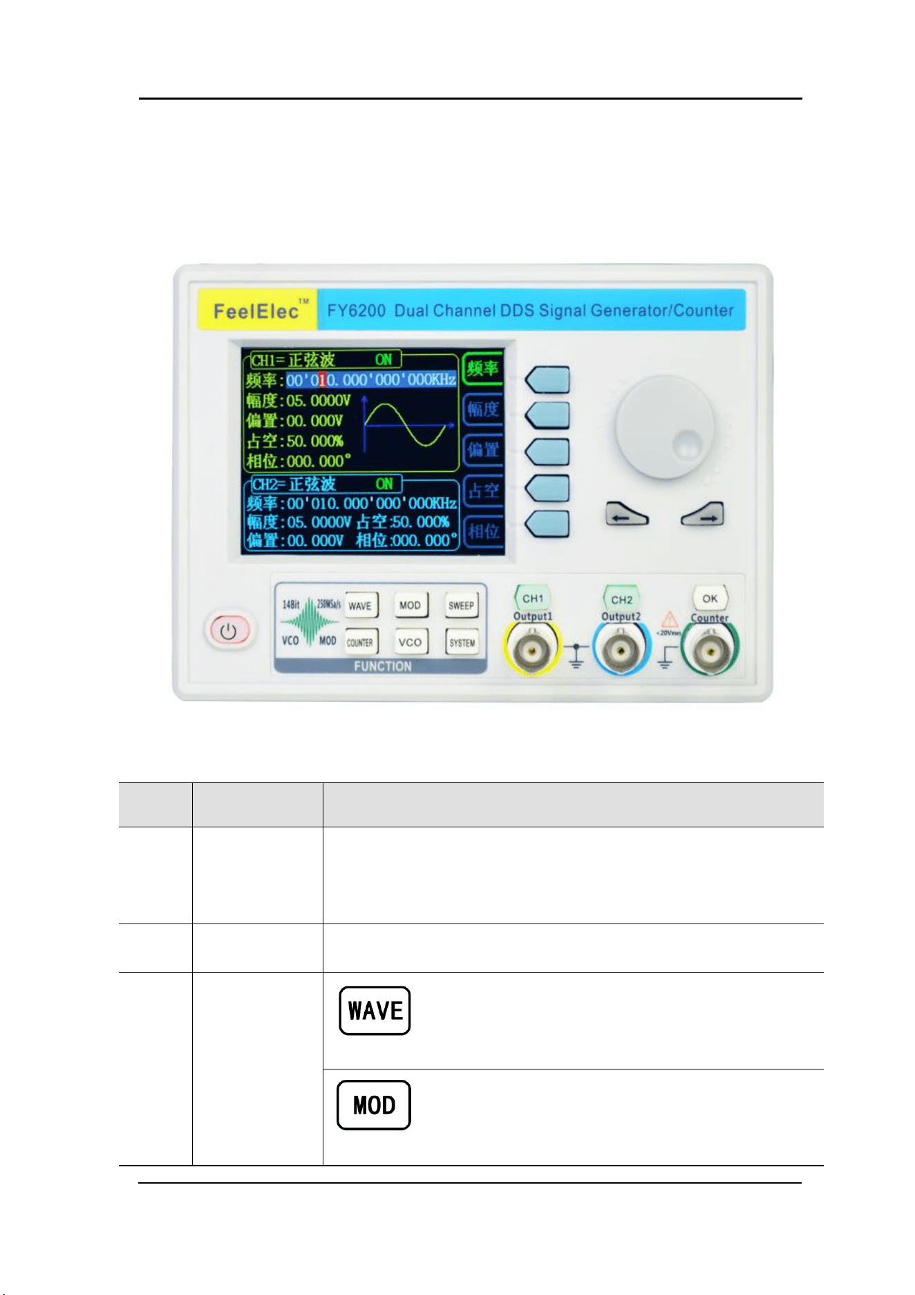
1-1 Front Panel
Item
Description
Explain
1
LCD
The 3.2 inch TFT (320 x 240) color LCD displays the menu and
parameter settings, system status and prompt message of the
current function. Please refer to the “User Interface” section for
details.
2
Manu Buttons
Corresponding to the menu displayed on the left, press this soft key
to activate the corresponding menu.
3
Function
shortcut,
Function for
switching signal
generator
Waveform selection button:
— You can switch between sine, square wave,
triangle wave, and any type of arbitrary wave
— Change the selected channel signal type
Trigger and modulation function buttons
— Can set a specific number of pulse train output
function(BURS)
— Modulation mode can be set :ASK、FSK、PSK、AM、
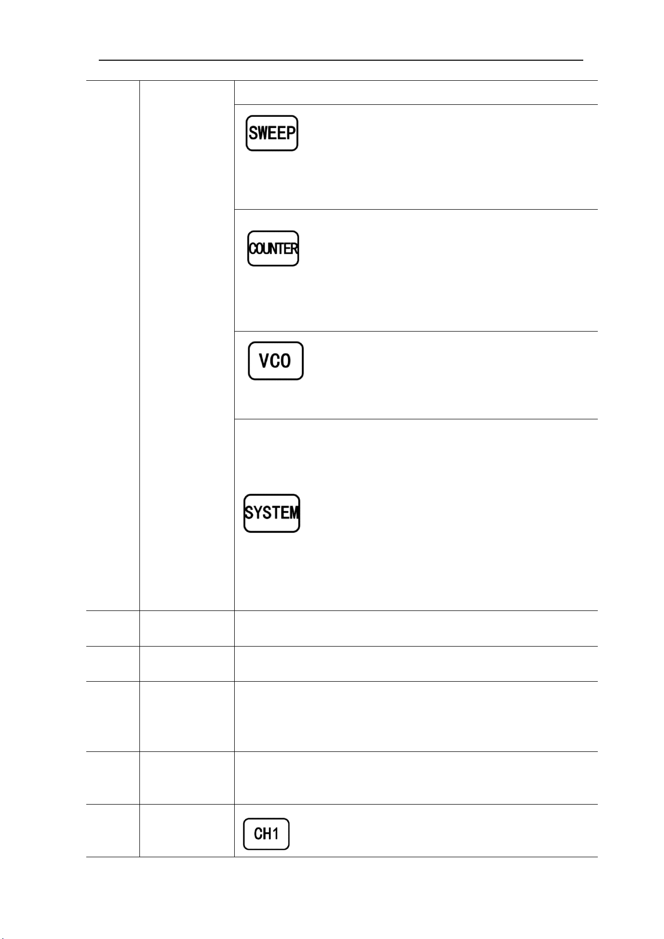
FM、PM
Sine, square, sawtooth and arbitrary waveforms can
be scanned.
— Supports scanning of four parameters of
frequency, amplitude, offset, and duty cycle.
— Supports two linear and logarithmic scanning
methods.
Can switch to frequency meter and counter function,
measure frequency, period, duty cycle, positive pulse
width of external input signal.
— Supports DC and AC signal input
— Supports 1 s, 10 s and 100 s gate time switching.
— Dual channel output can work with frequency
meter measurement.
VCO function can be set
— Support VCO voltage control signal generator's
frequency, amplitude, offset, duty cycle and other
parameter output functions (such as voltage-
controlled oscillator).
Used to set auxiliary function parameters and system
parameters.
— Supports storage of 20 sets of parameters such as
frequency, amplitude, offset, and phase
— Support Chinese and English switching
— Support prompt tone off/on
— Supports multi-machine cascading
— Supports master/slave switchover in cascaded
state
— Supports dual-channel power-on default output
state setting
4
Direction key
When the knob is used to set parameters, it is used to move the
cursor to select the bit to be edited.
5
Adjusting knob
When using the knob to set parameters, you can increase (clockwise)
or decrease (counterclockwise) the value at the current cursor.
6
Power button
The power indicator will remain on when it is turned on.
When the signal generator is turned off, the indicator light will enter
the breathing lamp state and CH1 and CH2 will stop outputting (the
output will remain at 0 volts).
7
CH1 channel
output
Connector
BNC connector, nominal output impedance 50Ω.
When channel CH1 is on (the CH1 button indicator lights up), the
connector outputs the waveform in the current configuration of CH1.
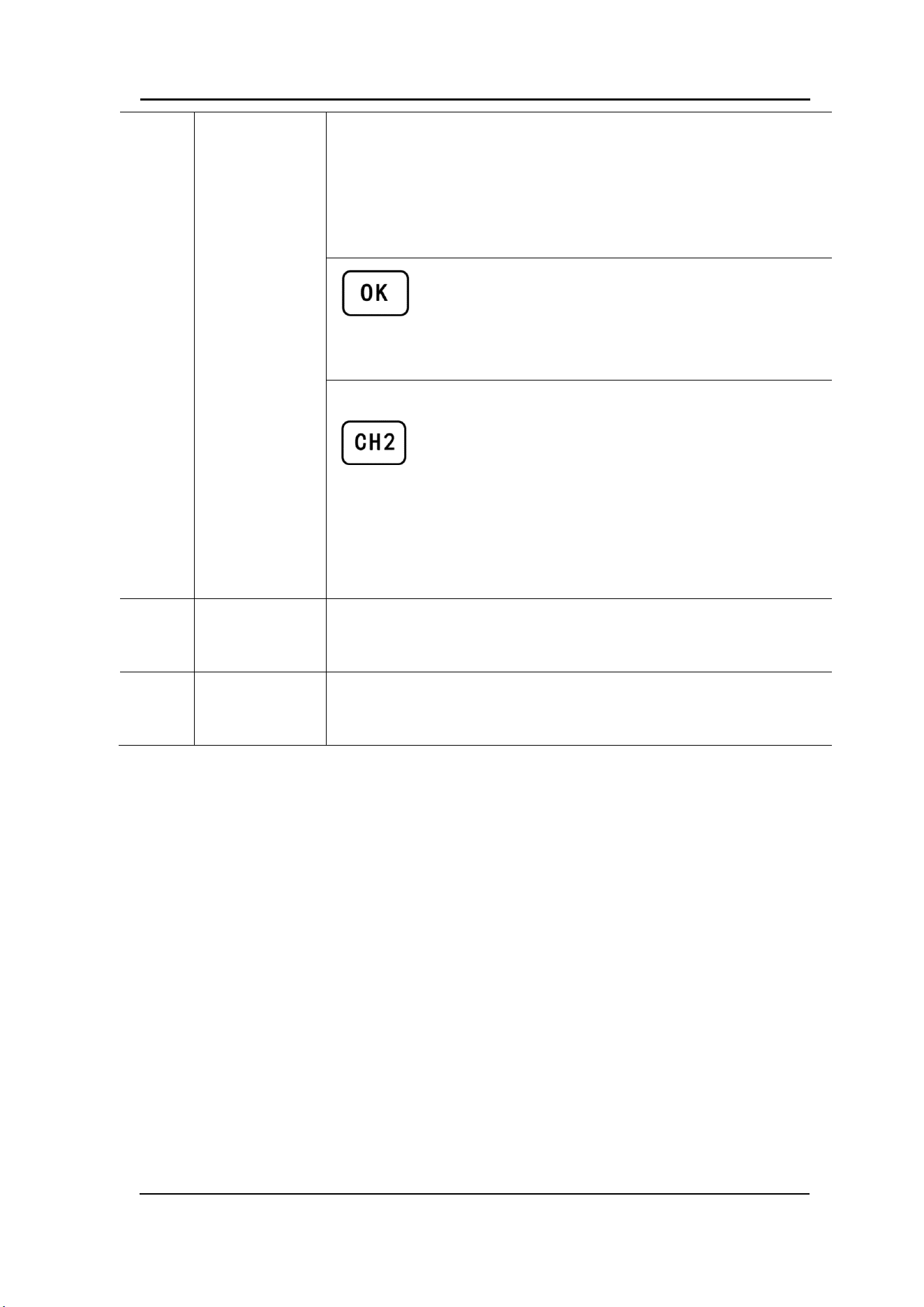
8
Channel
control,
Confirm button
It is used to control the output of the CH1 channel and
can be switched to the CH1 parameter setting interface
in any interface.
FeelElec
FY6200 系列用户手册 9
— Press this button, the CH1 light will turn on, and the
CH1 output will turn on. At this point, the [CH1]
connector outputs the signal in the current
configuration.
— Press this button again, the indicator light goes off,
and at this point, the CH1 output is turned off
Confirm button
— When editing frequency parameters, press this key
to change the frequency unit.
— When scanning the interface, press this button to
start/stop scanning.
It is used to control the output of the CH1 channel and
can be switched to the CH1 parameter setting interface
in any interface.
— Press this button, the CH2 light will turn on, and the
CH2 output will turn on. At this point, the [CH2]
connector outputs the signal in the current
configuration.
— Press this button again, the indicator light goes off,
and at this point, the CH2 output is turned off.
9
CH2 channel
output
connector
BNC connector, nominal output impedance 50Ω.
When channel CH2 is on (the CH2 button indicator lights up), the
connector outputs the waveform in the current configuration of CH2.
10
AC coupling
measuring
terminal
BNC connector, input impedance 100Ω. For inputting signal of meter
or counter.
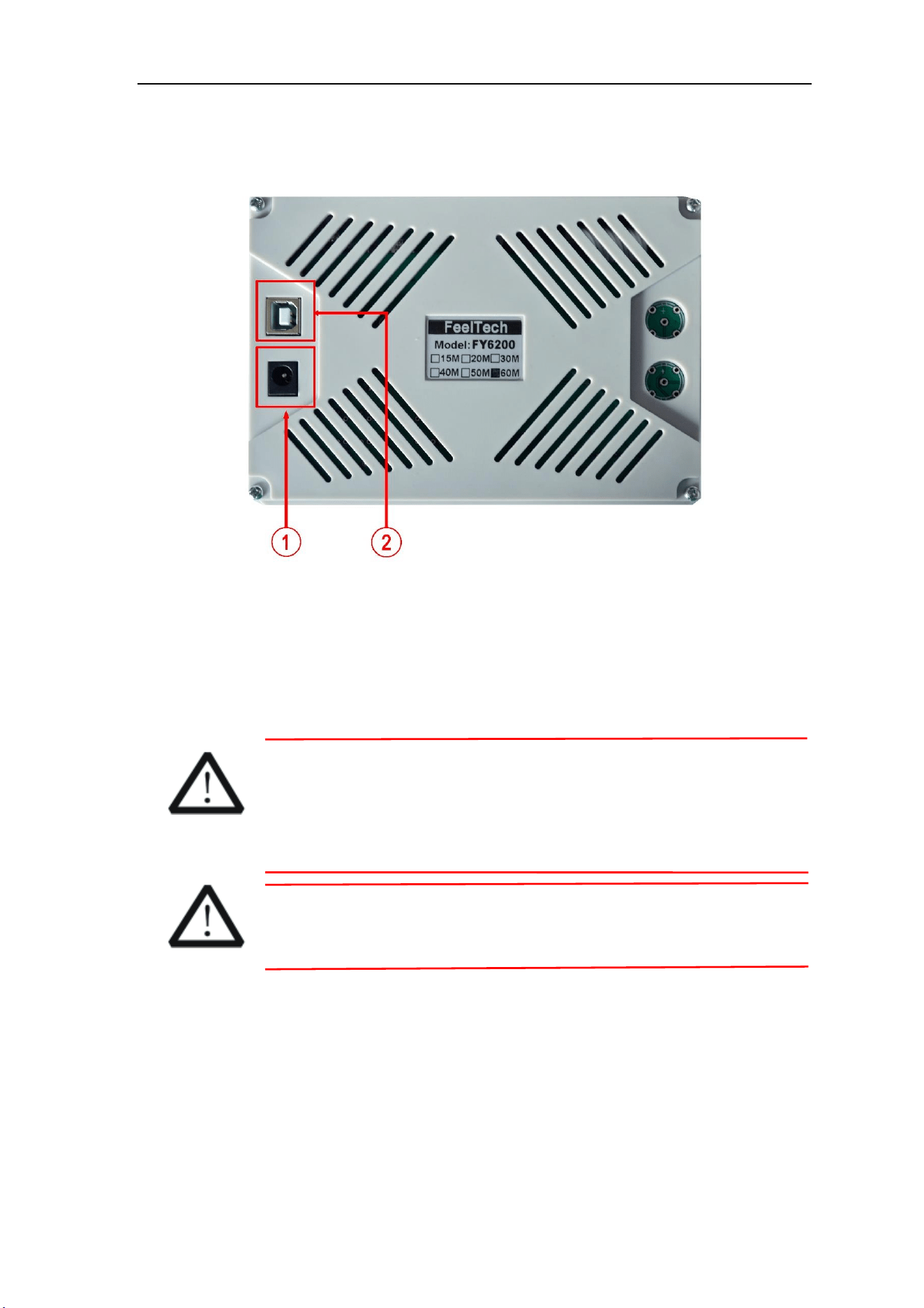
Back Panel Overview
1-2 Back Panel
1. Power input interface, input voltage DC5V 1.5A.
2. USB Device Interface
Used to communicate with the computer. (this is a USB to TTL serial port. You
need to install a serial driver). Through the upper computer software or user-
defined programming.
Warning
In order to avoid damaging the instrument, the voltage range of
the input signal of the ext.in terminal shall not exceed ± 20Vac +
dc. The input signal voltage range of Trig / FSK / ASK / PSK in
terminal shall not exceed DC5V.
Note
In order to ensure the normal operation of the instrument, please
use 5V 1.5A DC power supply.

FeelElec
FY6200 系列用户手册 11
Power On and Inspection
Connect to Power
Please use the power supply provided by the accessory to connect
to the DC power connector on the back of the signal generator. The
signal generator supports DC power of DC5V specification, and the
power consumption of the whole machine is less than 3W.
Power On
Turn on the power switch after the power cord is connected. The generator
will execute self-inspection. The LCD will show welcome interface after the
inspection is over. If the generator cannot work normally, please check the Chapter
“Fault Handing” for solution.
Set the System Language
FY6200 series Function/Arbitrary Waveform Generator supports Chinese and
English system languages. You can press SYSTEM→CONF to switch the system
language.
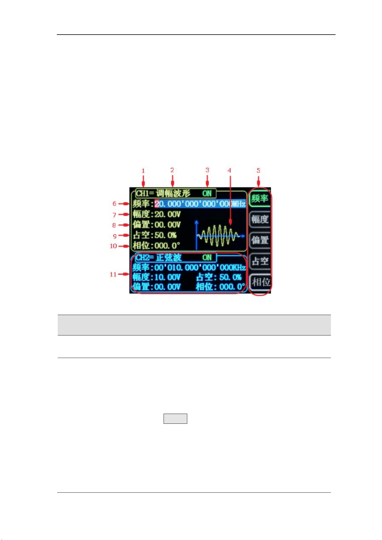
User Interface
The user interface of fy6200 includes four display modes: dual channel
parameter display mode, single channel extended display mode, additional
function display mode and system configuration display mode.
Dual Channels Parameters
The upper half of LCD displays the channel selected currently and the
parameters can be set. Press CH1 or CH2 to change current channel selected.
1-4 User Interface(CH1 channel is selected)
Item
Description
1
Current channel selected.
Display current channel selected for operation.
2
Current waveform type selected
Displays the name of the currently selected feature. For
example: "ch1 = amplitude modulation waveform" means that
the currently selected channel CH1 outputs amplitude
modulation waveform, and the waveform type can be changed
through the WAVE button on the front panel. In addition,
when the change waveform type function is activated, you can
use the parameter adjustment knob to perform fast switching
on the waveform type or click the knob to quickly locate the
waveform. In the waveform adjustment state, the preset
waveform and customization can be realized by pressing the
OK button. Fast switching between waveforms.
FeelElec
FY6200 系列用户手册 13
3
Currently selected channel output status bar
The current channel output on / off status is displayed, and
the output status can be changed by adjusting the front panel
channel control buttons CH1 and CH2.
4
Waveform
Display diagram of current waveform(Including Arbitrary).
Yellow indicates CH1 and blue indicates CH2.(The instrument can
also display any user-defined waveform.)
5
Manu Bar
Displays the action menu for the currently selected function.
6
Frequency
Displays the frequency of the currently selected channel
waveform. Press the corresponding FREQ button to highlight the
"frequency" display value, and change the parameter through
the direction key and adjustment knob.
7
Amplitude
Displays the amplitude of the currently selected channel
waveform. Press the corresponding FREQ button to highlight
the "amplitude" display value, and change the parameter
through the direction key and knob.
8
Offset
Displays the DC offset of the currently selected channel
waveform. Press the corresponding OFFS button to highlight the
"offset" display value, and change the parameter through the
direction key and knob.
9
Duty Cycle
Display Duty Cycle value of current channel. Press DUTY
button to highlight it and use adjusting Knob and Arrows to change
the value.
10
Phase
Displays the phase of the current waveform for each channel.
After pressing the corresponding PHAS button menu, change the
parameter with the arrow keys and knob.
11
Channel parameter status is not selected
Displays information such as the frequency, amplitude, offset,
phase, duty cycle, and output status of the current waveform of
the unselected channel. The parameters in this column cannot be
directly changed under the current interface. If you need to
change, please switch the channel to the selected channel.
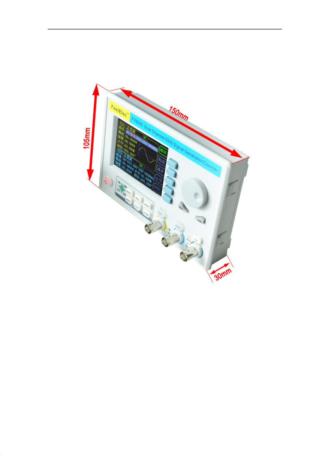
Dimensions

FeelElec
FY6200 系列用户手册 15
Front Panel Operations
Waveform Output
FY6200 series can output waveforms (Sine, Square, Triangle/Ramp, Pulse and
Noise etc.) from one of the channels separately or from the two channels at the
same time. At start-up, the dual channels are configured to output a sine waveform
with 10kHz frequency and 5Vpp amplitude by default. Two channels use default
setting saved at Position 1 when power on. Users can configure the instrument to
output various waveforms.
Select Output Channel
CH1、CH2 keys are used to switch ch1 or CH2 to the currently selected
channel. When power on, ch1 is selected by default and displayed in yellow on the
top half of the screen. Press the CH2 key on the front panel to select CH2, which
is displayed in blue on the top half of the screen. After selecting the required output
channel, you can configure the waveform and parameters of the selected channel.
KEY POINT:
CH1 and CH2 can not be selected at the same time. Users can first select CH1 and
then select CH2 after configuring the waveform and parameters of CH1. If you need
to change the parameters of two channel at same time, please refer to Chapter
“Synchronizing”.

Select Waveform
FY6200 can output Function/Arbitrary Waveform including:
⚫ Sine
⚫ Square
⚫ Triangle/Ramp
⚫ Rise Sawtooth
⚫ Fall Sawtooth
⚫ Lorenz Pulse
⚫ Multitone
⚫ Noise
⚫ Electrocardiogram (ECG)
⚫ Trapezoidal Pulse
⚫ Sinc Pulse
⚫ Narrow Pulse
⚫ Gauss White Noise
⚫ Step Triangle
⚫ Positive Step
⚫ Inverse Step
⚫ Positive Exponent
⚫ Inverse Exponent
⚫ Positive Falling Exponent
⚫ Inverse Falling Exponent
⚫ Positive Logarithm
⚫ Inverse Logarithm
⚫ Positive Falling Logarithm
⚫ Inverse Falling Logarithm
⚫ Linear FM
⚫ AM
⚫ FM
⚫ Positive Half Wave
⚫ Negative Half Wave
⚫ Positive Half Wave
Rectification
⚫ Negative Half Wave
Rectification
⚫ User-defined waveform
Press WAVE to change waveform selected. Or rotate ADJ Knob under waveform
switching status to change waveform. The waveform diagram displays on the
screen. Pressing the knob can change to arbitrary waveform directly when
choosing waveform. At start-up Sine is selected by default. (Users can also
configure start-up waveform. Please check Chapter “Save and Load”.)
Waveform
Sine
Square
Triangle
Sawtooth
Arbitrary
Function Name
SINE
SQUR
TRGL
RAMP
ARB
Parameter
Frequency
√
√
√
√
√
Amplitude
√
√
√
√
√
Offset
√
√
√
√
√
Phase
√
√
√
√
√
Duty Cycle
√
Note: the user-defined waveform can be edited and downloaded through the
fy6200 upper computer control software provided by feelelec. Relevant software
and drivers can be downloaded from our website: http://www.feelelec.com

FeelElec
FY6200 系列用户手册 17
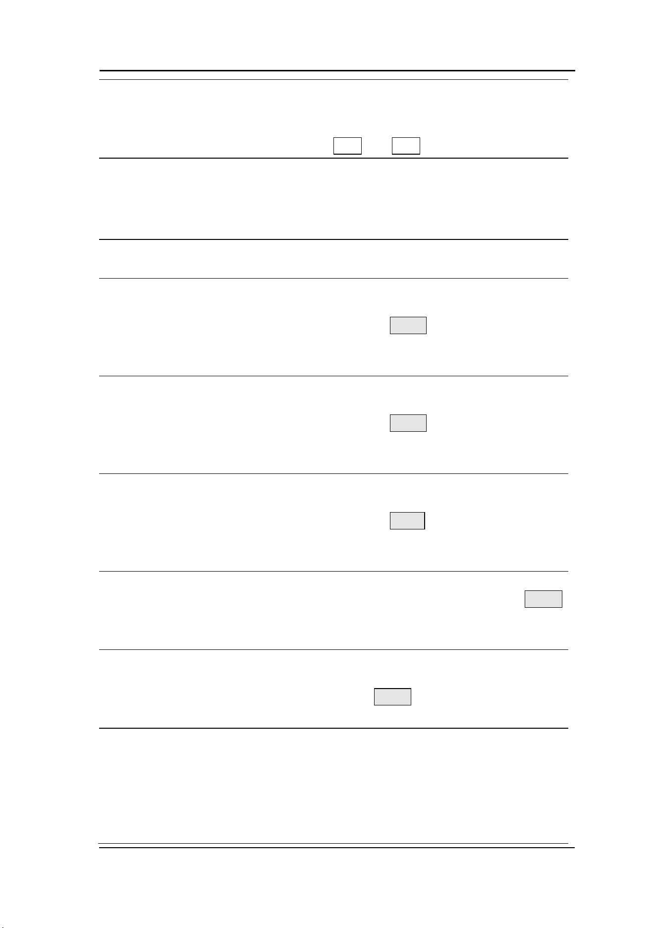
Set Frequency
Frequency is one of the most important parameters of the basic waveform.
The frequency can be set differently based on different signals and different
waveforms. Please refer to the description of “Frequency Characteristics” in
“Performance Specifications”. The factory default setting is 10KHz.
Press the FREQ soft key to highlight the frequency parameter. At this time,
use the direction key and knob to set the parameter value: use the direction key
to move the cursor to select the position to be edited, and then rotate the knob to
modify the value.
The frequency unit can be switched according to the user's requirements.
Press the OK key to change the frequency unit. The optional frequency units are:
MHz, kHz, Hz, MHz and μ Hz.
Set Amplitude
The settable range of amplitude is limited by the "frequency" setting. Please
refer to the description of "output characteristic" in "performance index". The
default is 5vpp.
Press the FREQ soft key to highlight the amplitude parameter. At this time,
use the direction key and the adjustment knob to set the value of the amplitude:
use the direction key to move the cursor to select the position to be edited, and
then rotate the knob to modify the value.
Key Points:
1.What is the difference between the amplitude in Vpp and the value in Vrms?
Answer:
Vpp is the unit of signal peak value, Vrms is the unit of signal effective value. Vpp is
used by default.
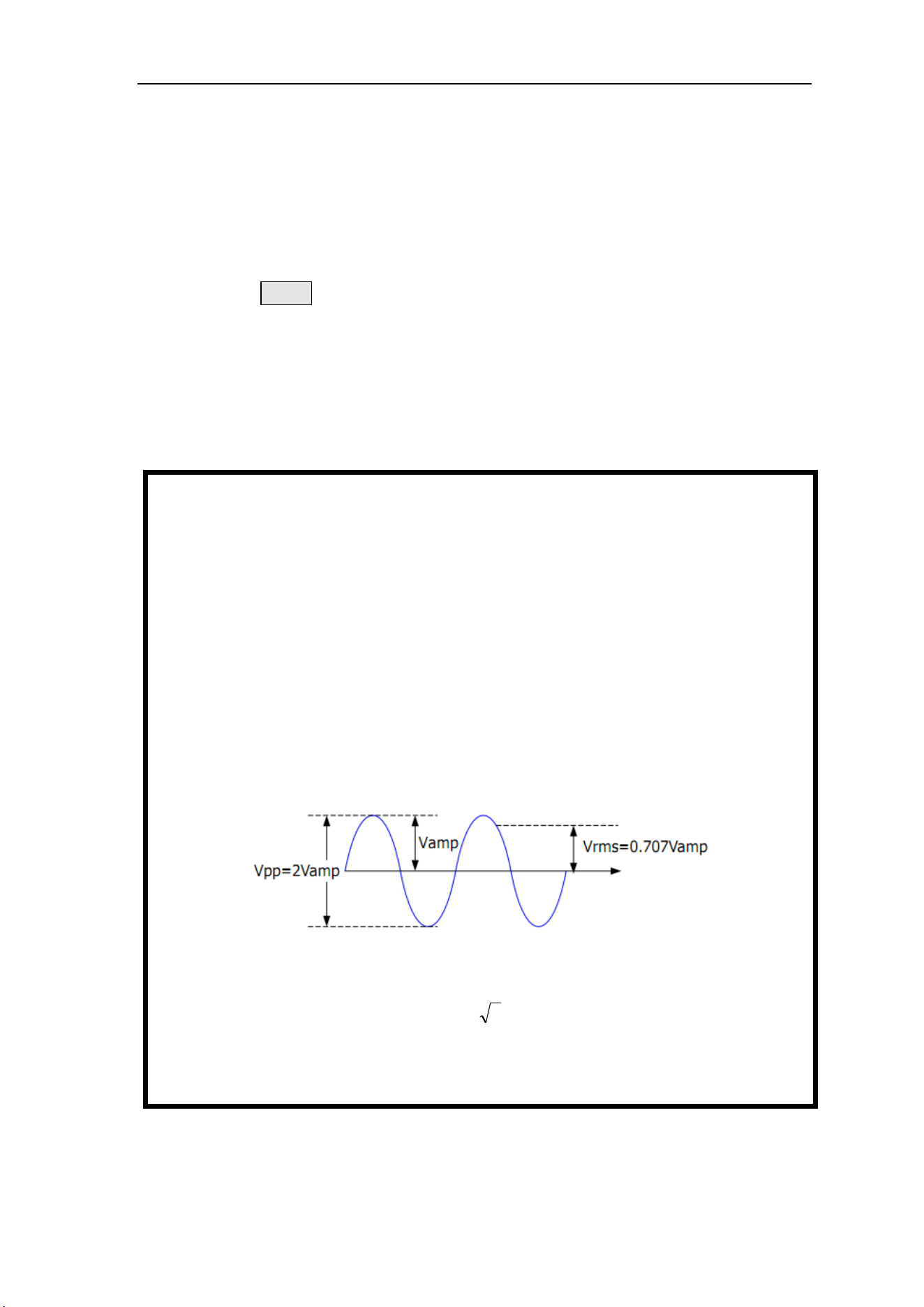
Explain:
For different waveforms, the relationship between Vpp and Vrms is different. Take the
sine wave as an example.
The relationship is shown in the figure below.
According to the above figure, it can be deduced that the conversion relationship
between Vpp and Vrms meets the following relationship:
Vpp = 2
2
Vrms
For example, for a sine wave with a current amplitude of 5Vpp, the converted value is
1.768Vrms.

FeelElec
FY6200 系列用户手册 19
Set Offset
Press the OFFS key to highlight the offset parameter. At this time, use the
direction key and adjustment knob to set the offset value: use the direction key to
move the cursor to select the position to be edited, and then rotate the knob to
modify the value.
The minimum adjustment accuracy of offset is 1mV (0.001V).
When the output frequency is lower than 20MHz, the bias voltage can be
adjusted arbitrarily between - 10V and + 10V.
When the output frequency exceeds 20MHz, the bias voltage can be adjusted
arbitrarily between - 2.5V and + 2.5V.
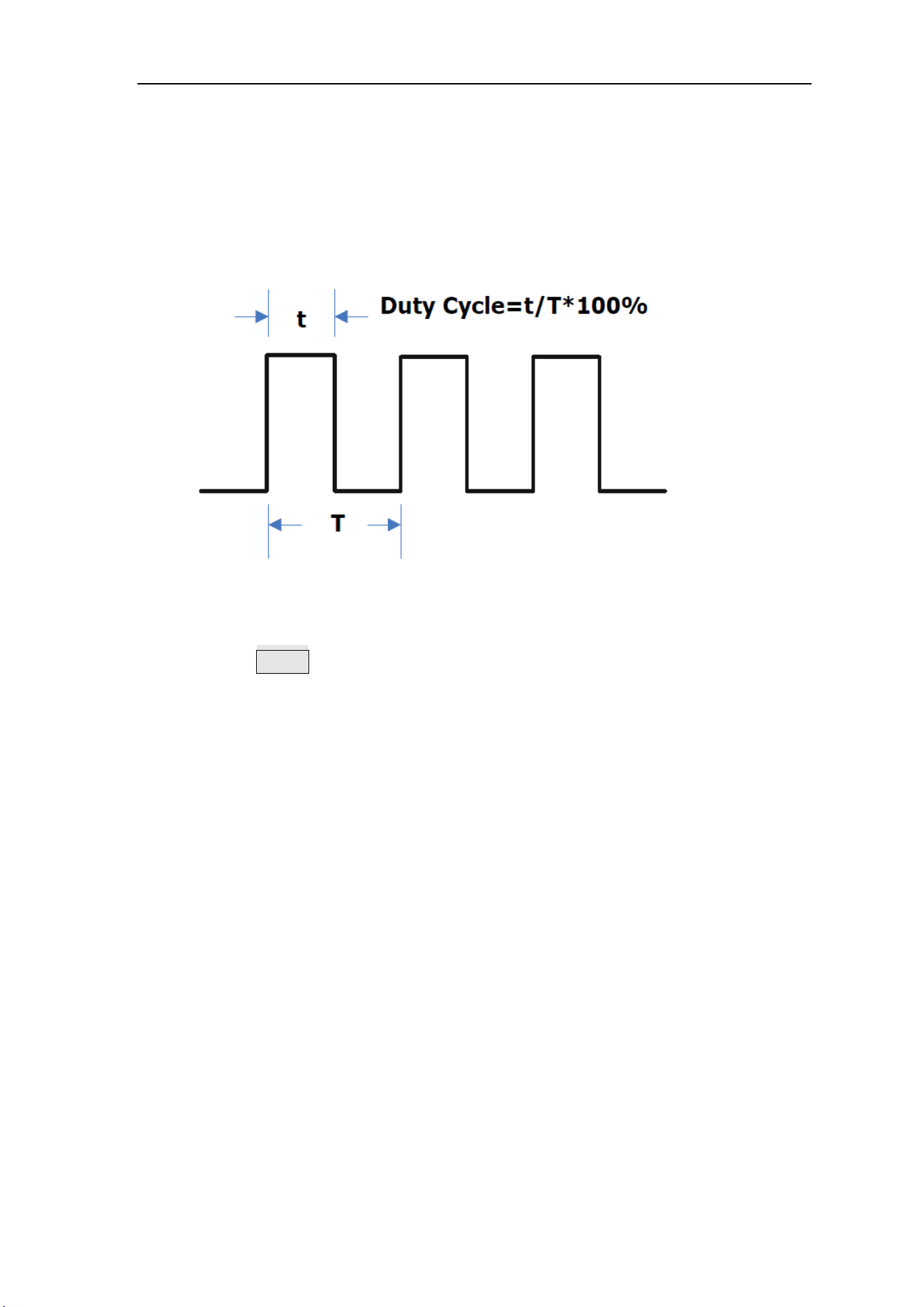
Set duty cycle (square wave)
Duty cycle is defined as the percentage of the duration of the high level of the
square wave in the cycle, as shown in the figure below. This parameter is only
valid when square wave is selected.
The setting range of duty cycle is limited by the “FREQ” setting. Please refer
to “Waveform Characteristics” in “Specifications”. The default value is 50%.
1. Press the DUTY soft key to highlight the duty cycle parameter. At this time,
use the direction key and knob to set the parameter value: use the direction
key to move the cursor to select the position to be edited, and then rotate the
knob to modify the value.
a. The adjusting range of duty cycle of this instrument is 0.01% - 99.99%.
b. Press the OK key in the duty cycle adjustment state, and the duty cycle
will be initialized to 50.0%.
2. Press duty cycle repeatedly to switch between rising edge time and falling edge
time.
Set pulse width (pulse wave)
The adjustable pulse wave refers to a square wave that can maintain a fixed
pulse width at any frequency, that is, the pulse width set by the user does not
change with the frequency change.
Pulse width setting method: when the tunable pulse wave is
selected, press the time key to adjust the duration of the pulse width t
(NS). Pulse width can be set by direction key and parameter adjusting knob. Use
the direction key to move the cursor to select the position to be edited, and then
turn the knob to modify the value.((Note: Please don’t make the set length of the

FeelElec
FY6200 系列用户手册 21
positive pulse width t greater than or equal to the period T length of the output
waveform).
Set Phase
The initial phase can be set from 0 ° to 359.99 ° and the phase resolution is
0.01 °. The default value is 0 °.
1. The starting phase of the screen display is the default value or the previously
set phase.
2. Press the PHAS soft key to highlight the phase parameters. At this time, use
the direction key to move the cursor to select the position to be edited, and
then turn the knob to modify the value.

Enable channel output
After completing the parameter settings for the selected waveform, you need
to turn on the channel to output the waveform. When the output is off, the LED
below the corresponding channel button is off; when the output is on, the LED is
lit.
The default CH1 and CH2 are enabled for output, and the LEDs under the CH1
and CH2 buttons are lit.
The power-on can also be set to the default off output state. Setting method:
Press the【SYS】button, and then press the【MORE】soft key to set the default
output status of the two channels.
⚫ To turn off/on the output on the CH1 channel, there are two states:
1. The signal generator works in the waveform parameter setting menu, and
the currently selected channel is CH1, Pressing the CH1 button will switch
the output between off/on.
2. The signal generator works in other function menus, or the selected
channel is not CH1,Press CH1 button once to make CH1 as the currently
selected channel. Press CH1 again to switch the output between off/on.
⚫ To turn off/on the output on the CH2 channel, there are two states:
1. The signal generator works in the waveform parameter setting menu, and
the currently selected channel is CH2. Pressing theCH2 button will switch
the output between off/on.
2. The current signal generator works in other function menus, or the selected
channel is not CH2. Press CH2 once to take CH2 as the currently selected
channel, and press CH2 again to switch the output between off / on.
FeelElec
FY6200 系列用户手册 23
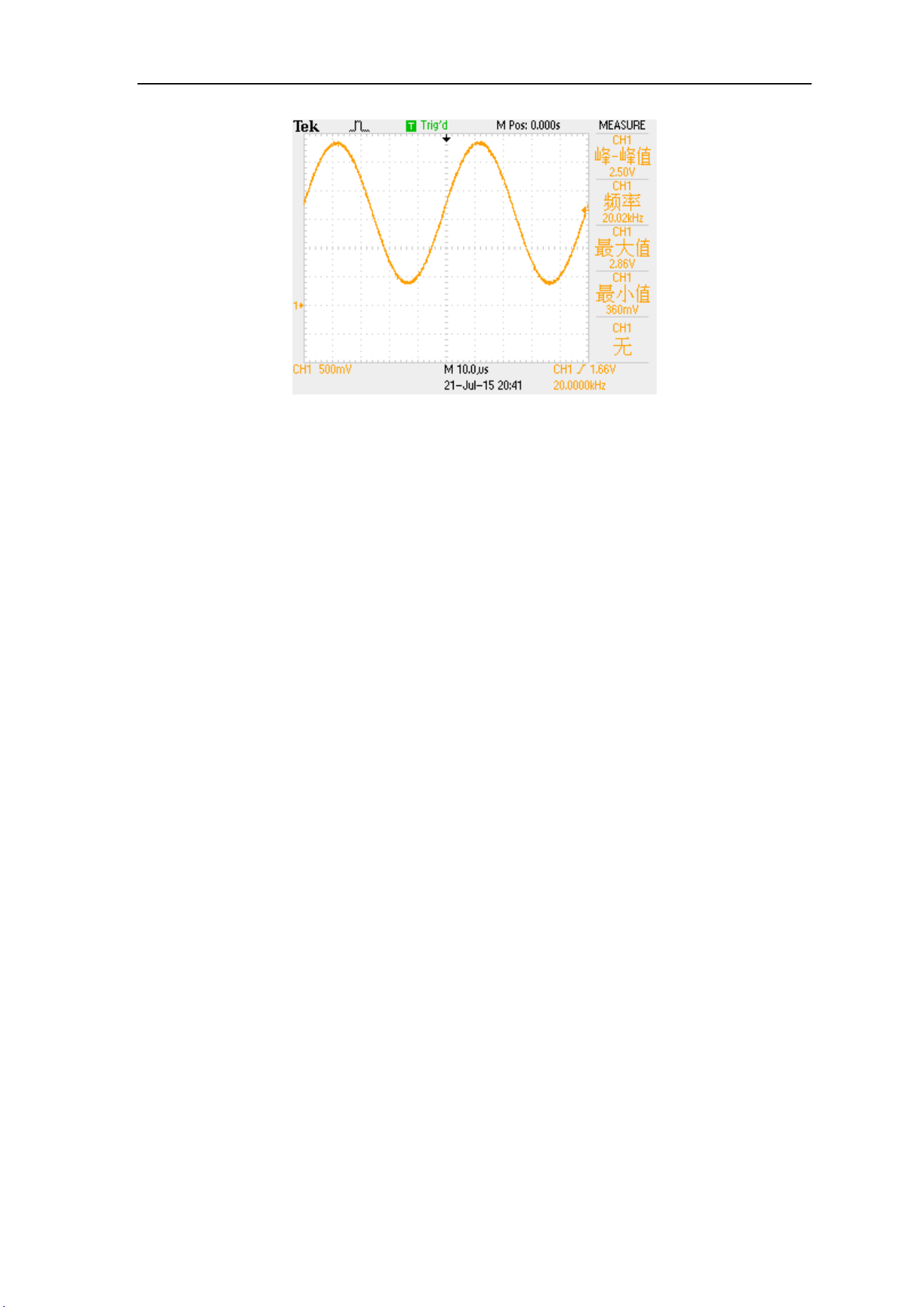
Example: output sine wave
This section mainly introduces how to output a sine wave from the [ch1]
connector (frequency 20KHz, amplitude 2.5vpp, offset 1.6vdc, initial phase 90.9 °)
1. Select output channel: Press CH1 to select CH1. Now all characters and
border of the channel is displayed in yellow.
2. Select the Sine: Press WAVE button to select Sine. Then the diagram of
Sine displays on the screen.
3. Set the frequency: Press FREQ button to highlight the frequency value.
press the direction key to adjust the cursor to the "2" position as shown in the
figure below, and rotate the adjustment knob to obtain the following data.
FREQ:00’020.000’000’000kHz
4. Set the Amplitude: Press AMPL to highlight the amplitude value, Press the
direction key and rotate the adjustment knob to obtain the following data.
AMPL:02.500V
5. Set the offset voltage: Press OFFS to highlight the offset value. Press the
direction key and rotate the adjustment knob to obtain the following data.
OFFS:01.600V
6. Set Phase: Press the PHAS soft key to highlight the "phase" parameter. Press
the direction key and rotate the adjustment knob to obtain the following data.
PHAS:090.90°
7. Enable channel output: Press the CH1 key to turn on the ch1 output light,
and the [CH1] connector outputs the sine wave signal in the current configuration.
8. Observe the output waveform: Connect the [CH1] of fy6200 to the
oscilloscope with BNC connecting wire. The following figure shows the waveform
observed by the oscilloscope.
FeelElec
FY6200 系列用户手册 25
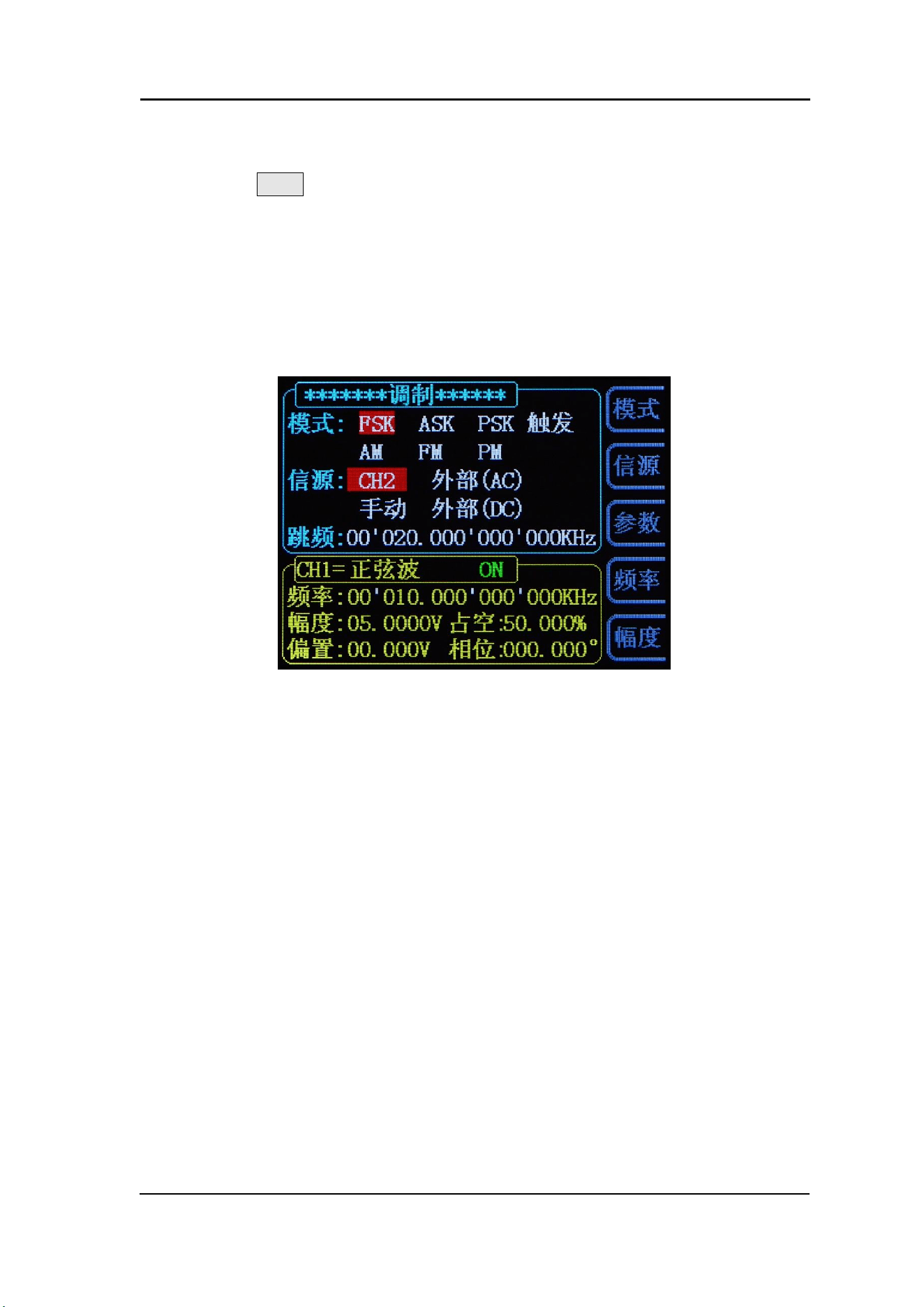
Modulation function
Press the MOD key on the front panel to enable the modulation function, and
fy6200 can output the modulation waveform from ch1 channel. This function uses
ch1 waveform signal as carrier, CH2 waveform signal, external signal or manual
pulse signal as modulation wave to modulate signal. It can realize FSK, ASK, PSK
digital modulation, trigger pulse series output, and AM, FM, PM analog signal
modulation functions. The modulation signal is input by Trig / FSK / ASK / PSK IN
at the tail of the signal generator.
2-3 Modulation parameter setting interface
( Note: after entering the modulation interface, the signal generator will
immediately perform the current modulation function.)

Modulation mode
Click the < F1 > mode key under the modulation function to switch the
modulation modes, including
① FSK (frequency keying)
② ASK (amplitude keying)
③ PSK (phase keying).
④ Trigger (controllable burst output).
⑤ AM (Amplitude Modulation).)
⑥ FM(Frequency modulation)
⑦ PM(Phase modulation)
Every time the "mode" button is pressed, the function will switch down once.

FeelElec
FY6200 系列用户手册 27
Modulation source
Under the modulation function, click the <F2> source button to switch the
modulation source, that is to say, select the modulation signal.
In FSK, ASK, PSK and Trigger modes, there are four sources:
① CH2: Channel 2 signal as modulation signal
② External (AC): access external signals in the form of AC coupling through
the EXT.IN port
③ Manual: click "OK" key manually as modulation signal
④ External (DC): access external signals in the form of DC coupling through
TTL_IO port.
There are two sources in AM, FM and PM modes:
① CH2: Channel 2 signal as modulation signal
② External (Ext.IN): access external signals in the form of DC coupling
through the EXT.IN port
Every time the "source" button is pressed, the function will switch down once

Modulation parameter
Click the < F3 > parameter key under the modulation function to adjust the
modulation parameters.
For Example:
① In the "FSK" mode, the frequency of frequency hopping can be adjusted.
② In the "trigger" mode, the number of output pulse trains can be adjusted.
③ In the "AM" mode, you can adjust the modulation rate of the amplitude modulation
(0 to 200%).
④ In FM mode, frequency offset parameters can be adjusted.
⑤ In the "PM" mode, the degree of phase deviation can be adjusted.
Other button functions
You can adjust the frequency of CH1 by clicking the <F4>“Frequency” button
under the modulation function.
You can adjust the amplitude of CH1 by clicking the <F5> “Amplitude” button
under the modulation function.
FeelElec
FY6200 系列用户手册 29
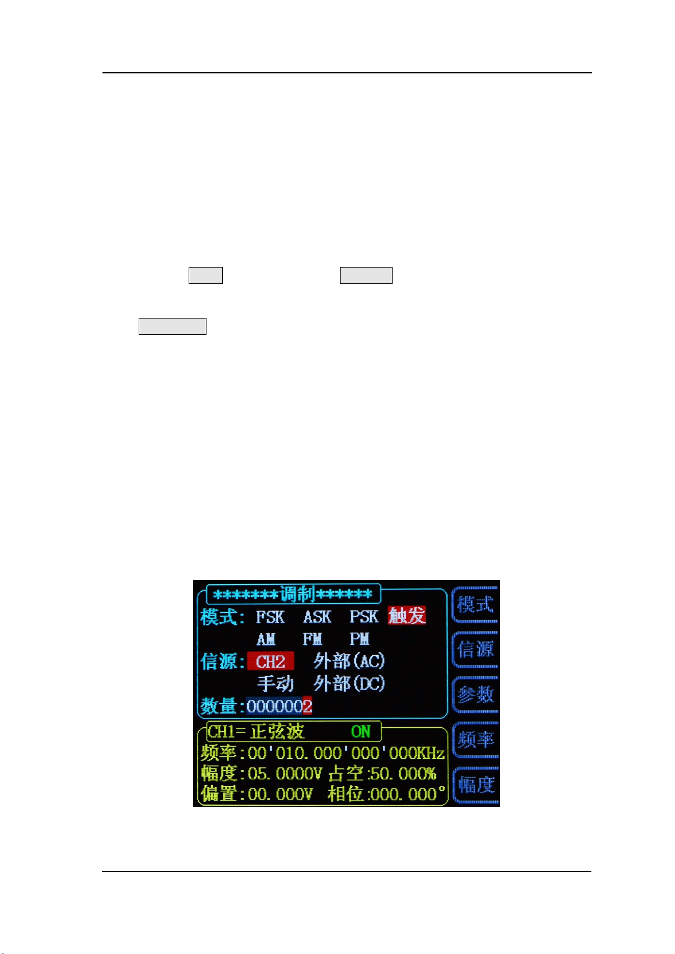
Pulse string
The FY6200 can output a waveform with the specified number of cycles from
the CH1 channel (called burst, Burst). Fy6200 supports the output of pulse strings
controlled by CH2 internal, manual or external trigger sources; the signal generator
can use sine wave, square wave, sawtooth wave, pulse, noise wave or any wave
(except DC) to generate pulse strings.
Enable burst function
Press the MOD key and press the BURS soft key to enter the burst burst
burst output function. The instrument supports [CH2], [external] and [manual]
three trigger output modes, which can be selected by corresponding soft keys.
Press COUNTER soft key to set the number of pulse strings. When the number
of pulses is selected, use the direction key and parameter adjustment knob to
change the number of single burst output pulses. The default value is 1, and the
setting range is 1 to 1048575. After the parameter setting, the signal generator
will output the pulse train waveform from ch1 channel (if it is currently on)
according to the current trigger configuration.
⚫ Normal mode, i.e. burst off mode.
⚫ CH2 triggering mode, that is, CH2 has a pulse generation, then CH1 outputs a
burst pulse waveform.
⚫ External trigger mode, that is, if Trig.IN terminal has a pulse input, CH1 will
output a burst pulse waveform.
⚫ Manual trigger mode, the user can press the [OK] key to trigger CH1 to output
a burst pulse waveform.
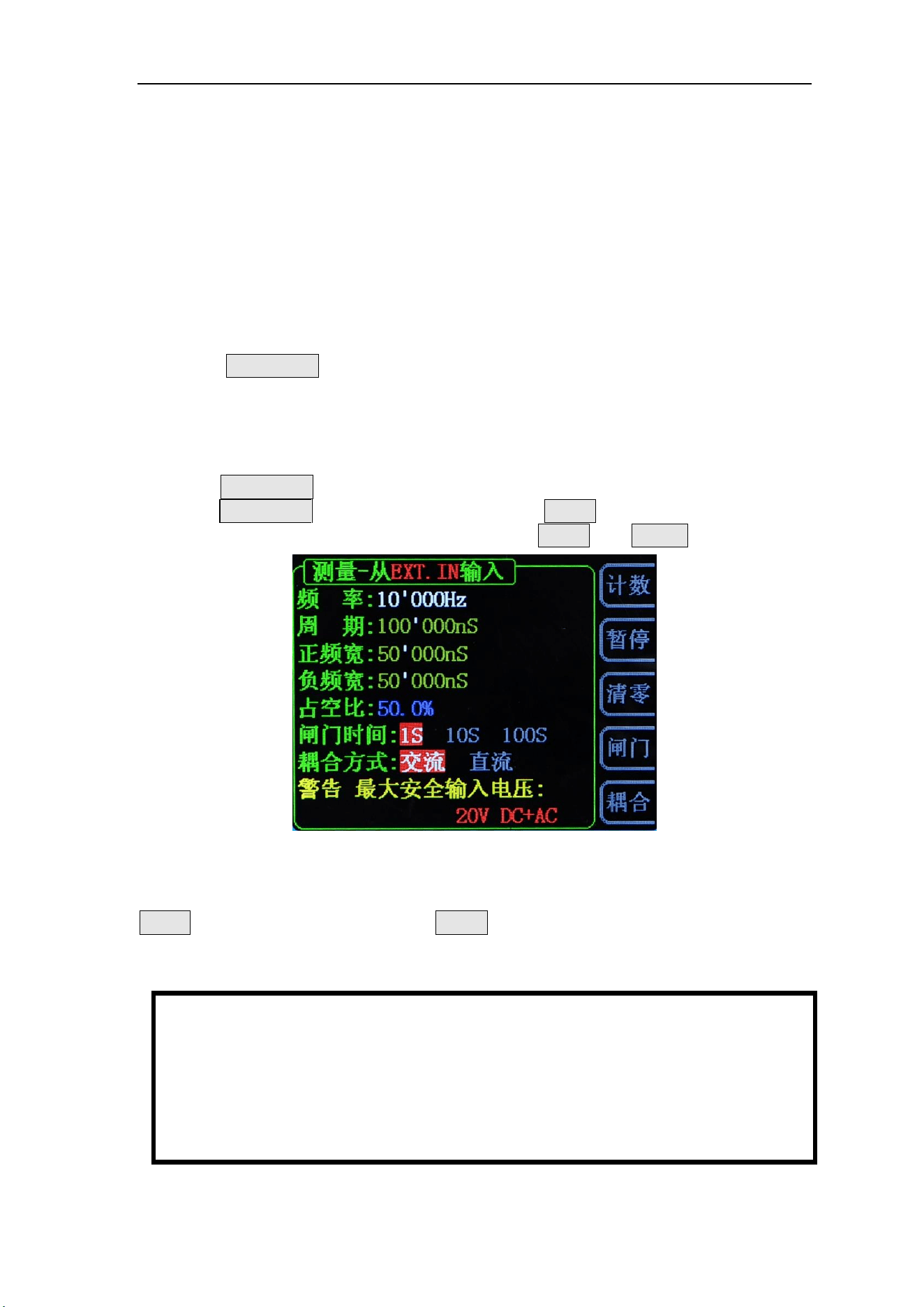
Frequency meter/counter
FY6200 provides the function of frequency meter/counter, which can measure
the frequency, period, duty cycle, positive pulse width, negative pulse width and
other parameters of external input signal. Dual channel output can work
simultaneously with the frequency meter measurement.
Enable frequency meter
Press COUNTER on the front panel to open the function of frequency meter
and display the setting interface of frequency meter. The measurement signal is
introduced from the input (AC coupling) or Trig.IN (DC coupling) terminal and
displayed on the screen in real time. The minimum frequency of measurement is
0.01Hz (gate time 100s).
⚫ Press COUNTER soft key to enter the external pulse counting function. At this
time, COUNTER soft key will be changed to FREQ.
⚫ Press this key repeatedly to switch between FREQ and COUN functions.
2-1 Frequency meter / counter parameter setting interface
If the current frequency meter is turned on, you can use the stop soft key to
STOP he screen content, and the ZERO soft key to set the frequency / count
value to zero.
Key Points:
The amplitude of the input signal of the frequency meter of the fy6200
series generator is greater than 1.5V, and the maximum safe input voltage of
the [counter] terminal is 20vpp. When using the function of frequency meter /
counter, please turn off the cascade function of the instrument.

FeelElec
FY6200 系列用户手册 31
Set frequency meter
Gate Time
Press the GATE soft key to select the gate time of the measurement system.
The default is 1s. When measuring low frequency signal, 10s or 100s gate time
can be selected.
Strobe time
Frequency resolution
1S
1Hz
10S
0.1Hz
100S
0.01Hz
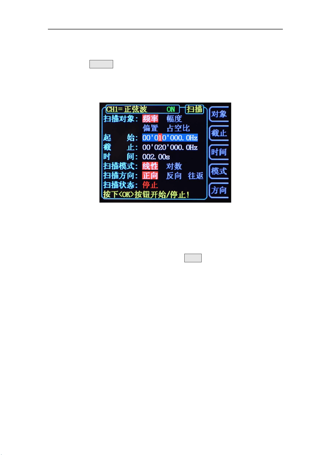
Sweep
Press the SWEEP key on the front panel to enable the scanning function, and
fy6200 can output the scanning waveform from ch1 channel. The process of
gradient scanning for a specific parameter object at a specified time from the initial
value to the termination value. For sine wave, square wave, sawtooth wave and
arbitrary wave, scanning output can be generated.
2-2 Sweep parameter setting interface
Sweep Object
The FY6200 can output sweep waveforms from the CH1 channel. The
parameters that can be scanned are: frequency, amplitude, offset, duty cycle.
Switching object types can be switched via the OBJE soft key.
⚫ In the frequency scanning mode, the signal generator changes the output from
the starting frequency to the ending frequency within the specified sweep time.
⚫ In the amplitude scanning mode, the signal generator changes the output from
the starting amplitude to the ending amplitude within the specified scanning
time.
⚫ In the offset scanning mode, the signal generator changes the output from the
start offset to the end offset within the specified scanning time.
⚫ In duty cycle scanning mode, the signal generator changes the output from
the start duty cycle to the end duty cycle within the specified scanning time.
FeelElec
FY6200 系列用户手册 33
Scanning start position
After the "Sweep" function key is enabled, the scan start value needs to be
set according to the scan object.
⚫ Frequency scanning: press the STAR soft key to highlight the "start"
parameter, press the direction key and rotate the adjustment knob to adjust
to the start value specified by the user, as shown in the following example.
START:00’010.000’000’000kHz
⚫ Amplitude scanning: press the STAR soft key to highlight the "start" parameter,
press the direction key and rotate the adjustment knob to adjust to the start
value specified by the user, as shown in the following example.
START:10.000V
⚫ Offset scanning: press the STAR soft key to highlight the "start" parameter,
press the direction key and rotate the adjustment knob to adjust to the start
value specified by the user, as shown in the following example.
START:00.000V
⚫ Duty cycle scanning: press the STAR soft key to highlight the "start" parameter,
press the direction key and rotate the adjustment knob to adjust to the start
value specified by the user, as shown in the following example.
START:50.0%
Sweep end position
When the sweep function key is enabled, you need to set the scan cut-off
value according to the scan object.
⚫ Frequency scanning: press the END soft key to highlight the "cut-off"
parameter, press the direction key and rotate the adjustment knob to adjust
to the cut-off value specified by the user, as shown in the following example.
END:00’020.000’000’000kHz
⚫ Amplitude scanning: press the END soft key to highlight the "cut-off"
parameter, press the direction key and rotate the adjustment knob to adjust
to the cut-off value specified by the user, as shown in the following example.
END:20.000V
⚫ Offset scanning: press the END soft key to highlight the "END" parameter,
press the direction key and rotate the adjustment knob to adjust to the cut-off
value specified by the user, as shown in the following example.
END:10.000V
⚫ Duty cycle scanning: press the END soft key to highlight the "END" parameter,
press the direction key and rotate the adjustment knob to adjust to the cut-off
value specified by the user, as shown in the following example.
END:80.0%
Sweep Time
When the scan function is enabled, press the [Time] soft key to highlight the
[time] parameter. Press the direction key and the parameter adjustment knob to
set the required scanning time value. The default is 2S, and the setting range is
10ms to 999.99s. The setting interface is as follows
TIME:002.00S

FeelElec
FY6200 系列用户手册 35
Sweep Type
FY6200 provides two types of scanning: linear scanning and logarithmic
scanning. The default is linear scanning. In the scan interface, press the mode soft
key to switch.
Linear sweep
Under the linear scanning mode, the parameters of the output signal of the
instrument change linearly.
Take frequency scanning as an example, i.e. changing the output frequency
by several Hertz per second, which is controlled by "start frequency", "end
frequency" and "scanning time".
The step value of the object parameter of linear scanning is calculated by the
signal generator, and the calculation formula is as follows:
Step value = (cut-off value - start value) / (scanning time * 100)
Logarithmic scanning
In the logarithmic scanning mode, the parameters of the output signal of the
instrument change in logarithmic mode.
Take the frequency sweep as an example, that is, change the output frequency
in octaves per second or ten times per second. The change is controlled by the
"starting frequency", "terminating frequency" and "scanning time".
When logarithmic sweep is enabled, the user can set the following parameters:
start frequency Fstart, stop frequency Fend and scan time Tsweep. The function
prototype of logarithmic sweep is:
F
current
=P
T
F
current
is the instantaneous frequency of the current output. The parameters
p and t can be expressed as follows with the above parameters.
P=10 lg
(Fend/Fstart)/Tsweep
T=t+lg(F
start
)/lg(P)
Among them, t is the time from the beginning of scavenging, ranging from 0
to T
sweep
.
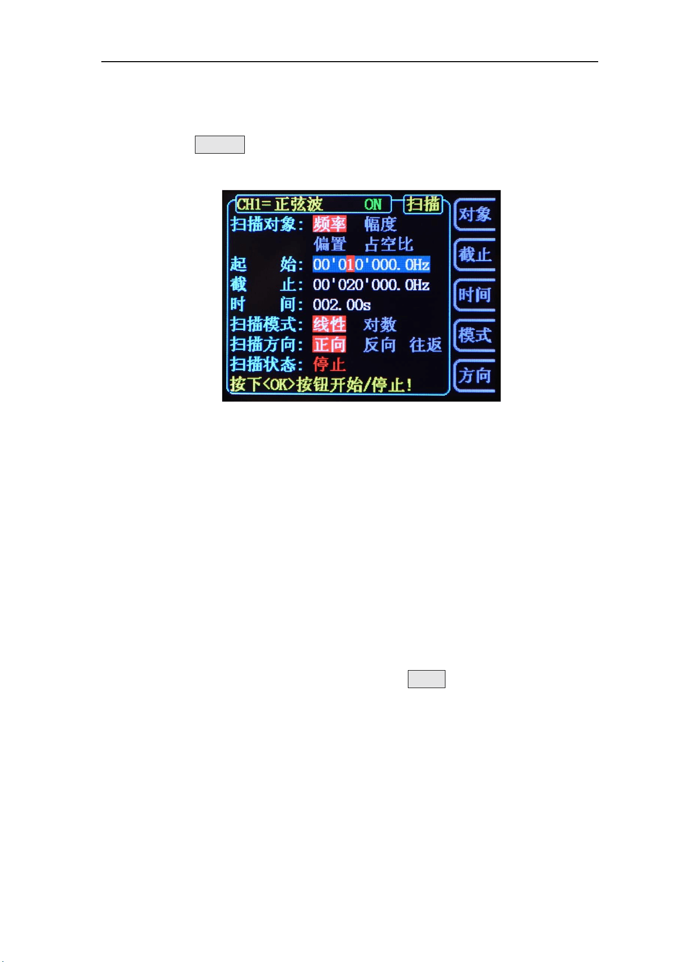
Enable frequency sweep function:
Press the SWEEP key on the front panel to enable the frequency sweep
function, press the OK key to start the scanning process, and press the OK key
again to stop the scanning.
Initial value and cut-off value
Initial and cut-off values are the upper and lower bounds of parametric
scanning. The signal generator always scans from the start value to the end value
of the parameter, then returns to the start value, and circulates.
Here is an example of frequency scanning:
When the starting frequency is < the ending frequency, the signal generator
scans from low frequency to high frequency.
When the starting frequency > the ending frequency, the signal generator
scans from high frequency to low frequency。
When the starting frequency = the ending frequency, the signal generator
outputs at a fixed frequency.
When the sweep mode is enabled, press the STAR soft key to highlight the
start parameter. Use the direction key and the knob to enter the desired frequency
value. The start and end frequency ranges of different sweep waveforms are
different.
Sine wave: 100MHz to the highest output frequency of this type of sine wave
Square wave: 100MHz to 25MHz
Sawtooth wave: 100MHz to 10MHz
Arbitrary wave: 100MHz to 10MHz
After modifying the "starting frequency" or "terminating frequency", the signal
generator will restart the sweep output from the specified "starting frequency".

FeelElec
FY6200 系列用户手册 37
VCO Sweep Function
Function introduction: The signal output of the external voltage control signal
generator can be realized by external scanning (VCO function). This function can
be realized: voltage control frequency (VCF), voltage control amplitude (VCA),
voltage control bias, voltage control duty cycle function. Note:VCO (Voltage
Control Output)
Operation method: Press the [VCO] button to enter the function interface.
After the scan object, start, cutoff, and scan mode settings are completed, connect
the external scan signal to the [Counter] port on the instrument panel. At this
point, press the OK button to start the VCO scan function. Press OK again, the
scan stops.
Note: The input signal of the external scan (VCO function) needs to be input from
the [Counter] port on the front panel of the signal generator. The input signal
frequency should be within 1000Hz, and the voltage amplitude must be between
0~5V.
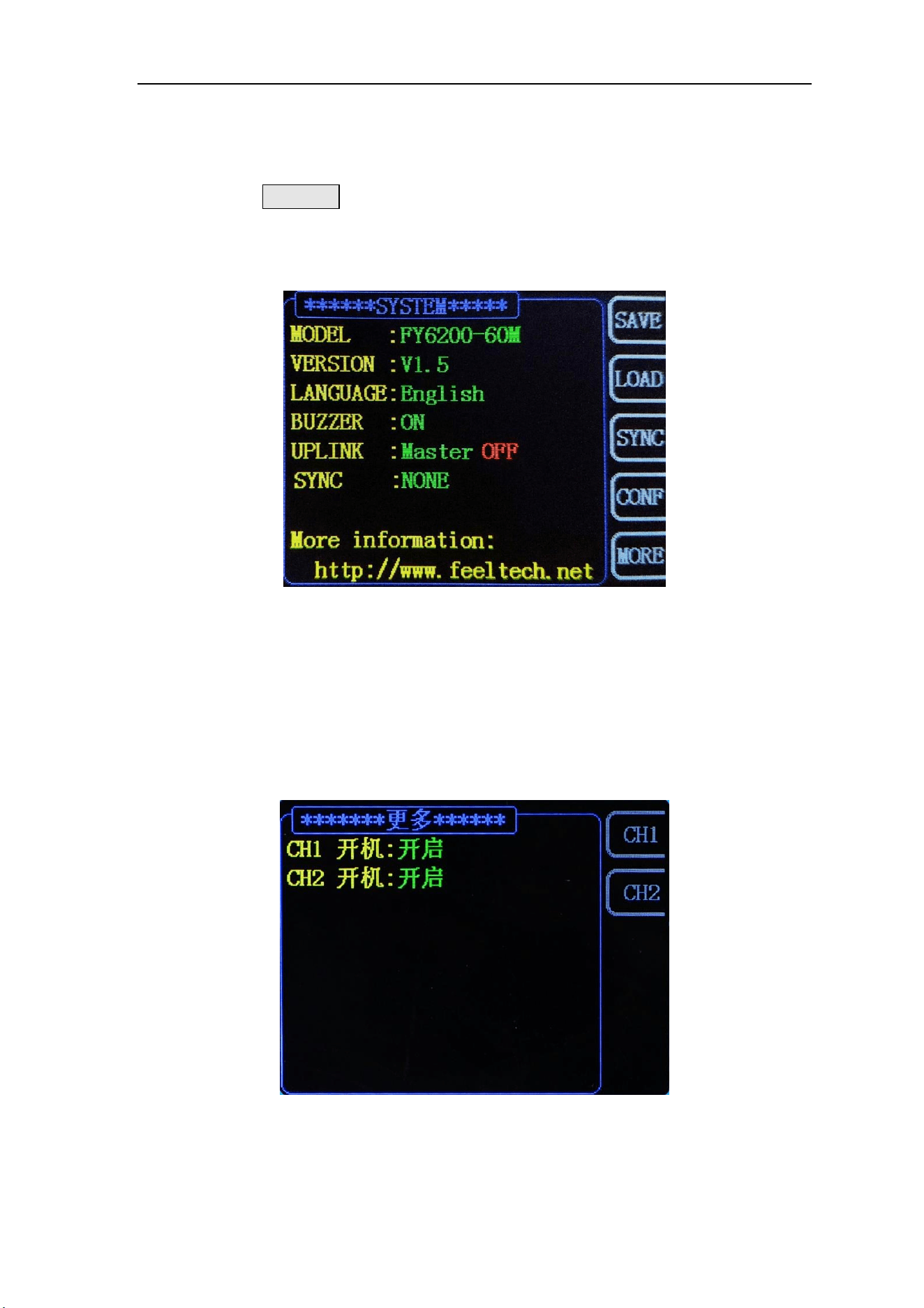
System settings and auxiliary functions
Press the SYSTEM key on the front panel to open the operation interface
shown in the figure below. This interface displays the function information of
instrument parameter storage, parameter loading, synchronization, configuration,
etc.
⚫ SAVE:The current waveform parameters can be stored in 20 groups of storage
areas of the system.
⚫ LOAD:The preset parameter information in the system can be loaded into the
current working state.
⚫ CONF:The system language can be set, the on / off of prompt tone, the on /
off of multi machine cascade function, and the mode setting in the cascade
state.
⚫ MORE:The default output state of CH1 and CH2 channel power on can be set.

FeelElec
FY6200 系列用户手册 39
SAVE and LOAD
In the system interface, press the SAVE soft key to store the information of
the current system waveform in the specified storage location; press the LOAD
soft key to load the previously stored system waveform parameter information into
the current system status.
Select the SAVE soft key on the right to store the current system parameters
in the corresponding storage location.
Select the right LOAD soft key to load system parameters from the
corresponding position.
⚫ FY6200 provides 20 groups of available storage areas。
⚫ The signal generator is powered on by default and automatically stores the
storage 1 position data parameter.

Configuration
Press the【SYSTEM】key to enter the system interface, press the SYSTEM
soft key to enter the system configuration interface, press the right parameter soft
key to set the system's working mode.
⚫ Press the 中文 soft key and select the system prompt language as Chinese.
⚫ Press the Eng soft key and select the system prompt language as English.
⚫ Press the BUZZ soft key to switch the system button tone between on/off
status, and the system default tone is turned on.

FeelElec
FY6200 系列用户手册 41
Synchronization function
After pressing the【SYSTEM】button, press the【Sync】soft key to enter the
synchronization function setting interface. Press the right parameter soft key to
switch it in the selected (highlighted) / canceled state.
When the synchronization of the corresponding parameters is turned on, the
corresponding parameter of CH2 changes according to the change of CH1, and no
human intervention is required. The synchronization parameters provided by the
FY6200 include: waveform, frequency, amplitude, offset, duty cycle, and can be
set separately.
⚫ WAVE The soft key is highlighted, and the waveform type of CH2 changes
synchronously with the waveform type of CH1.
⚫ FREQ The soft key is highlighted, and the waveform frequency of CH2 and
the waveform frequency of CH1 change synchronously.
⚫ AMPL The soft key is highlighted, and the waveform amplitude of CH2 and
the waveform amplitude of CH1 change synchronously.
⚫ OFFS The soft key is highlighted, the waveform offset of CH2 and the
waveform offset of CH1 are changed synchronously.
⚫ DUTY The soft key is highlighted, and the duty cycle of CH2 and the duty
cycle of CH1 change synchronously.

Fault Handling
The following is a list of faults and troubleshooting methods that may occur
during the use of the FY6200. When you encounter these faults, please follow the
corresponding steps, if not, please contact FeelElec and provide the equipment
information of your machine (obtaining method: press the SYSTEM key to obtain
the system information.)
Fault phenomenon
Methods of Resolution
After the instrument is
connected to the power
supply, there is no display and
the channel indicator is not on
1) Check whether the power socket has power.
2) Check whether the power connector is
connected properly.
3) After the above inspection, restart the
instrument.
4) If you are still unable to use the product
properly, please contact FeelElec.
Signal generator CH2 locked
1) Check whether the signal generator works in
synchronous state. Press the SYSTEM button ->
SYNC to enter the synchronization setting interface
to cancel all synchronization parameters.
2) Restart the signal generator and unlock it.
Correct setting but no
waveform output
1) Check that the BNC cable is securely
connected to the corresponding [CH1] or [CH2]
channel output port.
2) Check BNC wire for internal damage.
3) Check whether the BNC wire is firmly
connected with the test instrument.
4) Check whether the side indicator light on the
[CH1] or [CH2] key is lit on. If it is not lit, press
the corresponding button to make its indicator
light.
5) If you still cannot use the product properly,
please contact FeelElec.

FeelElec
FY6200 系列用户手册 43
Technical Index
Unless otherwise stated, all technical specifications are guaranteed when the
following two conditions are met.
⚫ The signal generator is in the pass-through state.
⚫ The signal generator runs continuously for more than 30 minutes at the
specified operating temperature (18 ° C to 28 ° C).
Technical specifications
Frequency characteristics
Product number
FY6200-20M
FY6200-30M
FY6200-50M
FY6200-60M
Sine wave
0~20MHz
0~30MHz
0~50MHz
0~60MHz
Square wave
0~15MHz
0~20MHz
0~25MHz
0~25MHz
Triangular wave
0~10MHz
0~10MHz
0~10MHz
0~10MHz
Pulse wave
0~10MHz
0~10MHz
0~10MHz
0~10MHz
Arbitrary wave
0~10MHz
0~10MHz
0~10MHz
0~10MHz
TTL/CMOS Digital wave
0~10MHz
0~20MHz
0~20MHz
0~20MHz
Minimum pulse width
20ns(The minimum adjustable width of all types of pulse wave can reach 20ns)
Min. Resolution on all
frequency range
1μHz (The minimum resolution of the whole frequency band can reach 1uhz, so as to ensure
the adjustment accuracy of the instrument at high frequency. For example, the instrument can
output 10.000000000001MHz high-precision signal.)
Frequency Accuracy
±20ppm
Frequency stability
±1ppm/ 3 hours
Waveform Characteristic
Waveform Catalog
Sine wave, square wave (duty cycle adjustable), pulse wave (pulse width and cycle time can
be accurately set), triangle wave, rising sawtooth wave, falling sawtooth wave, CMOS wave,
DC level, half wave, full wave, positive ladder wave, anti ladder wave, exponential rise,
exponential fall, Lorentz pulse wave, multi sound wave, irregular noise wave, ECG wave,
trapezoid pulse wave, cinke pulse wave, narrow Pulse wave, Gaussian white noise wave,
amplitude modulation wave, frequency modulation wave, and 64 user-defined waves.
Nonvolatile storage (64)
64 user-defined arbitrary waveforms can be stored
Waveform Length
8192 points (8K points) * 14bits
Sampling rate
250MSa/s
Vertical Resolution
14 bits
Sine Wave
Harmonic suppression system
≥50dBc(<1MHz);≥45dBc(1MHz~20MHz);
Total harmonic distortion
<0.5% (20Hz~20kHz,0dBm)
Rising and falling time
≤7ns(VPP<5V)

Square and Pulse wave
overshoot
≤5%
Duty cycle adjustment range
0.01%~99.99% (Resolution 0.01%)
Sawtooth wave
linearity
≥98% (0.01Hz~10kHz)
Output characteristics
Amplitude(VPP)
Frequency≤10MHz
10MHz<Frequency
≤20MHz
Frequency>20MHz
1mVpp~20Vpp
1mVpp~10Vpp,
1mVpp~5Vpp
Amplitude Resolution
1mV
Amplitude Stability
±0.5%/ 5 hours
Amplitude flatness
±5%(<10MHz);±10%(>10MHz);
Waveform Output
Output Impedance
50Ω±10%(Typical)
Protection
All signal output terminals can work for more than 60s under load short circuit condition
DC Offset
Offset Range
Frequency≤20MHz:±10V; Frequency>20MHz: ±2.5V
Offset Resolution
1mV (Minimum)
Phase Feature
Adjustable Range
0~359.99°
Minimum resolution
0.01°
TTL Output
TTL Level Amplitude
>3Vpp
Fan-out coefficient
>8 TTL Load
Rise/Fall Time
≤10ns
CMOS Output
Low Electric Level
<0.3V
High Electric Level
1V~10V
Rise/Fall Time
≤18ns
External measuring function
Function
It can measure frequency, period, positive pulse width, negative pulse width and duty cycle
of external signal.
Input signal voltage range
2Vpp~20Vpp
Function of frequency meter
Frequency measurement range
0.01Hz~100MHz
measurement accuracy
Gate time 1s, 10s, 100s three speed regulation

FeelElec
FY6200 系列用户手册 45
Counter function
Counting range
0-4294967295
counting mode
Manual
Pulse width measurement
10ns Resolution,Maximum measurable 20S
Cycle measurement
10ns Resolution,Maximum measurable 20S
Sweep Function
Carrier waveform
Sine wave, square wave, sawtooth wave, arbitrary wave (excluding DC voltage)
Sweep Type
Linear sweep, logarithmic sweep
Sweep Direction
Forward, reverse, round trip
Sweep Object
Frequency, amplitude, offset, duty cycle
Sweep Time
0.01S~999.99S/ stepping
Setting Range
Arbitrary setting of start point and end point
Sweep Range
Determined by sweep parameter setting value
VCO Function
Note:VCO (Voltage Control Output)
Modulation signal range
to input
0~5V
VCO signal frequency
range
0-1000Hz
VCO control object
• Voltage-controlled frequency(VCF)Voltage control range(VCA)Voltage-controlled
bias voltage controlled duty ratio
VCO Feature
Amplitude modulation(AM)or frequency modulation(FM)can be performed by an
external analog signal
Modulation function
Modulation Type
AM, FM, PM, ASK, FSK, PSK
Carrier waveform
Sine wave, square wave, triangle wave, sawtooth wave, arbitrary wave (except DC voltage)
AM
Source
Internal(CH2)/ External(Counter)
Modulation Waveform
Sine wave, square wave, triangle wave, sawtooth wave, arbitrary wave
Modulation Depth
0% to 100%
Modulation Frequency
Internal: 1μHz~1MHz; External: 1μHz~2KHz;
FM
Source
Internal(CH2)/External(Counter)
Modulation Waveform
Sine wave, square wave, triangle wave, sawtooth wave, arbitrary wave
Modulation Frequency
Internal: 1μHz~1MHz; External: 1μHz~2KHz;
PM
Source
Internal(CH2)/ External(Counter)
Modulation Waveform
Sine wave, square wave, triangle wave, sawtooth wave, arbitrary wave
Phase shift range
0°~360°
Modulation Frequency
Internal: 1μHz~1MHz; External: 1μHz~2KHz;

ASK
Source
Internal(CH2) Manual
Modulation Waveform
50% Duty Cycle square wave
Keying frequency
1μHz~10MHz
FSK
Source
Internal(CH2) Manual
Modulation Waveform
50% Duty Cycle square wave
Keying Frequency
1μHz~10MHz
PSK
Source
Internal(CH2) Manual
Modulation Waveform
50% Duty Cycle square wave
Keying Frequency
1μHz~10MHz
Burst Function
Carrier waveform
Sine wave, square wave, triangle wave, sawtooth wave, arbitrary wave (except DC voltage)
Pulse Count
1-1048575
Burst Mode
Manual Burst, Internal Burst (CH2), External Burst (Counter)
General specifications
Display
Display Type
3.2-inch TFT color LCD display
Storage and Load
Quantity
20 sets
Location
01 to 20 (Power on by default to enter 01 storage location
parameters)
Connector
Interface mode
USB to serial interface
Communication Rate
115200 bps
Communication protocol
Using the command line, the agreement is open
Power supply
Voltage Range
AC100V~240V
Manufacturing
technique
Surface mount technology, large scale integrated circuit, high reliability and long service life
Warning Tone
Users can turn on or off through program settings
Operational
characteristics
All buttons are operated, and the knob is adjusted continuously.
Environment
condition
Temperature:0~40℃ Humidity:﹤80%
Size
150mm (Length)×105mm(Width) ×30mm(Height)
Weight
Mainframe(350g) Accessory(200g)

FeelElec
FY6200 系列用户手册 47
Appendix
Appendix A:Safety precautions
1. Before using the instrument, please check whether the power supply is normal to ensure
the normal use and personal safety of the instrument.
2. It must be used within the range of technical indexes of the instrument.
3. Please don't change the circuit of the instrument at will to avoid damaging the instrument
and endangering the safety.
Appendix B:Warning and personal injury
Please don't apply the product to the safety protection device or emergency stop device, and
any other application that may cause personal injury due to the failure of the product, unless
there is a special purpose or authorized use. Before installation and use, all technical indexes
in the instructions shall be referred to. Failure to comply with this recommendation may
result in death and serious personal injury. The company will not be liable for all
compensation for personal injury or death arising therefrom, and will be exempt from any
claims that may arise from this to the company's managers and employees, affiliated agents,
distributors, etc., including various costs, compensation fees, attorney fees, etc.
Appendix C: accessories and options
Description
数量
Main
Frame
FY6200 series signal generator
1
Standard
Accessories
DC5V DC power supply
1
USB cable
1
BNC Transfer clip cable (Q9 clip cable)
2
BNC-BNC Connecting cable
1
Warranty Card
1
• Optional
Accessories
FYA2000 serial power amplifier
FPA2000 serial power amplifier
Note: Accessories need to be ordered from the dealer
Appendix D:Summary of the warranty
FeelElec warrants that its products mainframe and accessories will be free
from defects in materials and workmanship within the warranty period. If a product
is proven to be defective within the respective period, FeelElec guarantees the
free replacement or repair of products which are approved defective. This product
enjoy 1 year warranty since its delivery. Damages caused by misuse, vandalism,
improper maintenance or force majeure are not covered by the warranty. Any
disassembly or amendment without permission will be deemed giving up warranty
rights consciously.