
IMPORTANT: Your new tool has been engineered and manufactured to WEN’s highest standards for dependability,
ease of operation, and operator safety. When properly cared for, this product will supply you years of rugged,
trouble-free performance. Pay close attention to the rules for safe operation, warnings, and cautions. If you use
your tool properly and for its intended purpose, you will enjoy years of safe, reliable service.
NEED HELP? CONTACT US!
Have product questions? Need technical support? Please feel free to contact us:
TECHSUPPOR[email protected]1-847-429-9263 (M-F 8AM-5PM CST)
For replacement parts and the most up-to-date instruction manuals, visit WENPRODUCTS.COM
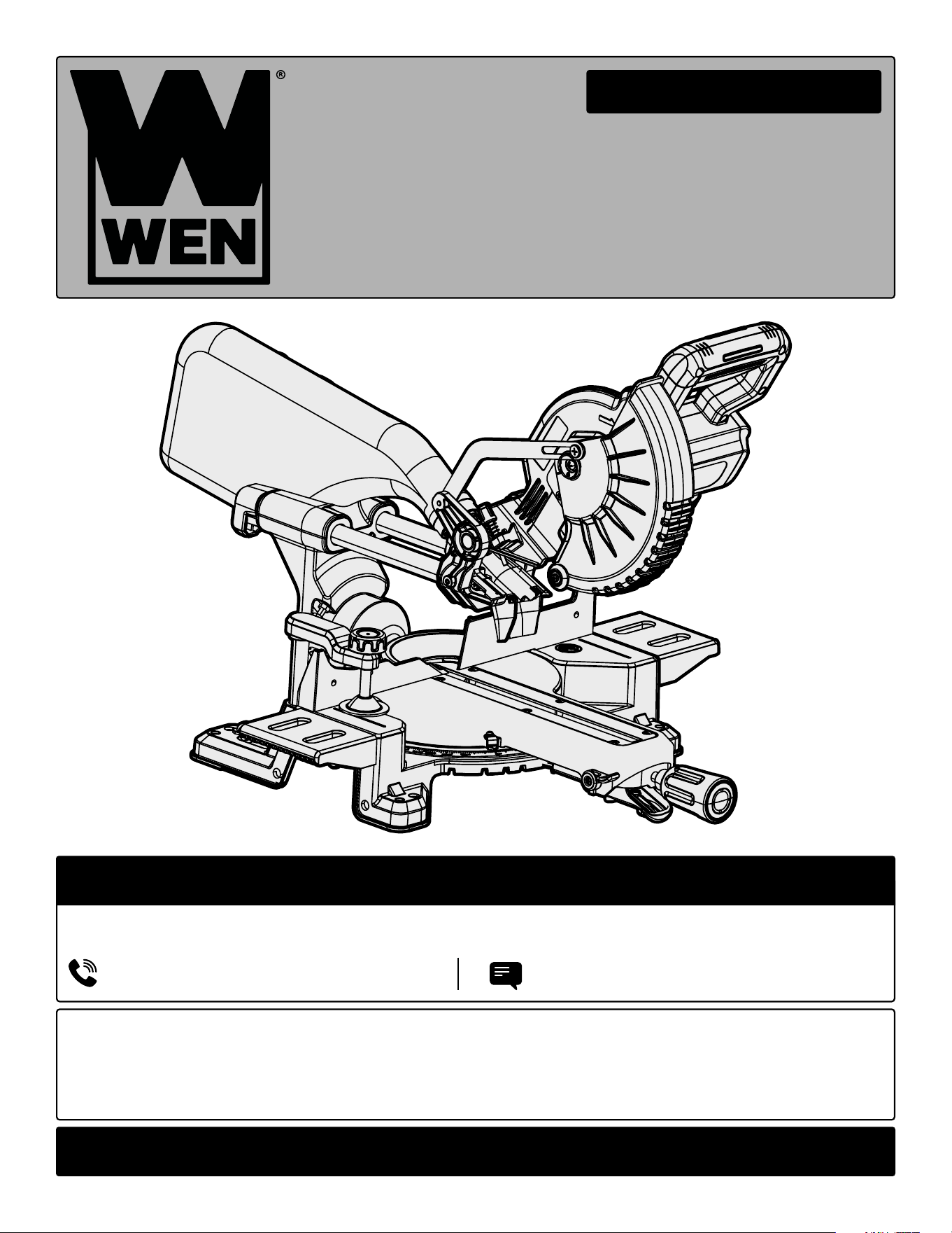
20V MAX BRUSHLESS
7¼-INCH MITER SAW
Instruction Manual
MODEL 20672, 20672BT
2
CONTENTS
WELCOME 3
Introduction ......................................................................................................3
Specifications ....................................................................................................3
SAFETY 4
General Safety Rules .........................................................................................4
Miter Saw Safety Warnings ...............................................................................6
Electrical Information ........................................................................................8
Battery & Charger Safety Warnings ..................................................................9
BEFORE OPERATING 11
Unpacking & Packing List ...............................................................................11
Know Your Miter Saw .....................................................................................12
Assembly & Adjustment ..................................................................................13
OPERATION & MAINTENANCE 17
Operation ........................................................................................................17
Maintenance ....................................................................................................18
Exploded View & Parts List .............................................................................21
Warranty Statement ........................................................................................27
To purchase accessories and replacement parts for your tool, visit WENPRODUCTS.COM
WEN plans to continue to add more items to our 20V line. For an up-to-date list of the 20V cordless tools compat-
ible with the included battery and charger, visit wenproducts.com.
20V 4.0Ah Max Battery (Model 20204)
20V 2A Charger (Model 20200C)
20V 5.0Ah Max Battery (Model 20205)
20V 5A Quick Charger (Model 20201Q)
20V 2.0Ah Max Battery (Model 20202)
Replacement Blade (Model BL0740)
20V 8.0Ah Max Battery (Model 20208)

SPECIFICATIONS
INTRODUCTION
Thanks for purchasing the WEN Miter Saw. We know you are excited to put your tool to work, but first, please
take a moment to read through the manual. Safe operation of this tool requires that you read and understand this
operator’s manual and all the labels affixed to the tool. This manual provides information regarding potential safety
concerns, as well as helpful assembly and operating instructions for your tool.
NOTE: The following safety information is not meant to cover all possible conditions and situations that may occur.
WEN reserves the right to change this product and specifications at any time without prior notice.
At WEN, we are continuously improving our products. If you find that your tool does not exactly match this manual,
please visit wenproducts.com for the most up-to-date manual or contact our customer service at 1-847-429-9263.
Keep this manual available to all users during the entire life of the tool and review it frequently to maximize
safety for both yourself and others.
Indicates danger, warning, or caution. The safety symbols and the explanations with them deserve your
careful attention and understanding. Always follow the safety precautions to reduce the risk of fire, electric shock
or personal injury. However, please note that these instructions and warnings are not substitutes for proper ac-
cident prevention measures.
3
Model Number 20672, 20672BT
Included Battery *4.0Ah Battery (Model 20204)
Included Charger *20V, 2A DC (Model 20200C)
Minimum Recommended Battery Capacity 4.0Ah
Blade 7-1/4 in. Diameter, 5/8 in. Arbor, 40 Teeth
No Load Speed 3800 RPM
Dust Port Outer Diameter: 1.46 in. Inner Diameter: 1.25 in.
Cutting Capacity at 0º
0° Miter, 0° Bevel: 9.25 in. x 2 in.
0° Miter, 45° Bevel: 9.25 in. x 1.5 in.
Cutting Capacity at 45º
45° Miter, 0° Bevel: 6.5 in. x 2 in.
45° Miter, 45° Bevel: 6.5 in. x 1.5 in.
Product Weight 18.92 lbs
Product Dimensions 25.35 in. x 16.22 in. x 12.99 in.
Battery Models All WEN 20V MAX Batteries**
Charger Models All WEN 20V MAX Chargers
**NOTE: Some tools may not be compatible with WEN 20V MAX 1.5Ah Batteries, model 49120B.
Contact WEN customer service at 1-847-429-9263, M-F with questions.
*NOTE: Battery and charger only included with model 20672. Model 20672BT does not include a
battery or charger.

4
GENERAL SAFETY RULES
WORK AREA SAFETY
1. Keep work area clean and well lit. Cluttered or dark
areas invite accidents.
2. Do not operate power tools in explosive atmo-
spheres, such as in the presence of flammable liquids,
gases or dust. Power tools create sparks which may ig-
nite the dust or fumes.
3. Keep children and bystanders away while operating
a power tool. Distractions can cause you to lose control.
ELECTRICAL SAFETY
1. Power tool plugs must match the outlet. Never mod-
ify the plug in any way. Do not use any adapter plugs
with earthed (grounded) power tools. Unmodified plugs
and matching outlets will reduce risk of electric shock.
2. Avoid body contact with earthed or grounded surfac-
es such as pipes, radiators, ranges and refrigerators.
There is an increased risk of electric shock if your body
is earthed or grounded.
3. Do not expose power tools to rain or wet conditions.
Water entering a power tool will increase the risk of elec-
tric shock.
4. Do not abuse the cord. Never use the cord for car-
rying, pulling or unplugging the power tool. Keep cord
away from heat, oil, sharp edges or moving parts.
Damaged or entangled cords increase the risk of electric
shock.
5. When operating a power tool outdoors, use an ex-
tension cord suitable for outdoor use. Use of a cord
suitable for outdoor use reduces the risk of electric
shock.
6. If operating a power tool in a damp location is un-
avoidable, use a ground fault circuit interrupter (GFCI)
protected supply. Use of a GFCI reduces the risk of elec-
tric shock.
PERSONAL SAFETY
1. Stay alert, watch what you are doing and use com-
mon sense when operating a power tool. Do not use a
power tool while you are tired or under the influence
of drugs, alcohol or medication. A moment of inatten-
tion while operating power tools may result in serious
personal injury.
2. Use personal protective equipment. Always wear
eye protection. Protective equipment such as a respira-
tory mask, non-skid safety shoes and hearing protection
used for appropriate conditions will reduce the risk of
personal injury.
3. Prevent unintentional starting. Ensure the switch is
in the off-position before connecting to power source
and/or battery pack, picking up or carrying the tool.
Carrying power tools with your finger on the switch or
energizing power tools that have the switch on invites
accidents.
4. Remove any adjusting key or wrench before turning
the power tool on. A wrench or a key left attached to a
rotating part of the power tool may result in personal
injury.
5. Do not overreach. Keep proper footing and balance
at all times. This enables better control of the power
tool in unexpected situations.
6. Dress properly. Do not wear loose clothing or jew-
elry. Keep your hair and clothing away from moving
parts. Loose clothes, jewelry or long hair can be caught
in moving parts.
Safety is a combination of common sense, staying alert and knowing how your item works. The term “power tool”
in the warnings refers to your mains-operated (corded) power tool or battery-operated (cordless) power tool.
SAVE THESE SAFETY INSTRUCTIONS.
WARNING! Read all safety warnings and all instructions. Failure to follow the warnings and instructions may
result in electric shock, fire and/or serious injury.

5
GENERAL SAFETY RULES
7. If devices are provided for the connection of dust
extraction and collection facilities, ensure these are
connected and properly used. Use of dust collection
can reduce dust-related hazards.
POWER TOOL USE AND CARE
1. Do not force the power tool. Use the correct power
tool for your application. The correct power tool will
do the job better and safer at the rate for which it was
designed.
2. Do not use the power tool if the switch does not turn
it on and off. Any power tool that cannot be controlled
with the switch is dangerous and must be repaired.
3. Disconnect the plug from the power source and/or
the battery pack from the power tool before making
any adjustments, changing accessories, or storing
power tools. Such preventive safety measures reduce
the risk of starting the power tool accidentally.
4. Store idle power tools out of the reach of children
and do not allow persons unfamiliar with the power
tool or these instructions to operate the power tool.
Power tools are dangerous in the hands of untrained us-
ers.
5. Maintain power tools. Check for misalignment or
binding of moving parts, breakage of parts and any
other condition that may affect the power tool’s opera-
tion. If damaged, have the power tool repaired before
use. Many accidents are caused by poorly maintained
power tools.
6. Keep cutting tools sharp and clean. Properly main-
tained cutting tools with sharp cutting edges are less
likely to bind and are easier to control.
7. Use the power tool, accessories and tool bits, etc.
in accordance with these instructions, taking into ac-
count the working conditions and the work to be per-
formed. Use of the power tool for operations different
from those intended could result in a hazardous situa-
tion.
8. Use clamps to secure your workpiece to a stable
surface. Holding a workpiece by hand or using your
body to support it may lead to loss of control.
9. KEEP GUARDS IN PLACE and in working order.
SERVICE
1. Have your power tool serviced by a qualified repair
person using only identical replacement parts. This
will ensure that the safety of the power tool is main-
tained.
CALIFORNIA PROPOSITION 65 WARNING
Some dust created by power sanding, sawing, grinding,
drilling, and other construction activities may contain
chemicals, including lead, known to the State of Califor-
nia to cause cancer, birth defects, or other reproductive
harm. Wash hands after handling. Some examples of
these chemicals are:
• Lead from lead-based paints.
• Crystalline silica from bricks, cement, and other
masonry products.
• Arsenic and chromium from chemically treated
lumber.
Your risk from these exposures varies depending on
how often you do this type of work. To reduce your ex-
posure to these chemicals, work in a well-ventilated area
with approved safety equipment such as dust masks
specially designed to filter out microscopic particles.
Safety is a combination of common sense, staying alert and knowing how your item works. The term “power tool”
in the warnings refers to your mains-operated (corded) power tool or battery-operated (cordless) power tool.
SAVE THESE SAFETY INSTRUCTIONS.
WARNING! Read all safety warnings and all instructions. Failure to follow the warnings and instructions may
result in electric shock, fire and/or serious injury.

SAW BLADE SAFETY
1. Always wear protective gloves when handling saw
blades.
2. Only use blades with correct size and type for both
your miter saw and your workpiece.
3. The rated diameter of the saw blade is 7-1/4 inches
with a 5/8 inch arbor.
4. The no-load speed of the Miter Saw is 3800 RPM. The
maximum permissible speed of your saw blade should
always be higher than the no-load rotational speed of
the saw.
5. Never use damaged or deformed saw blades. Only use
sharp blades.
6. Install the saw blade in the correct orientation indi-
cated in the instructions.
7. Keep hands out of path of saw blade. Never use your
hands to remove sawdust, chips or workpieces near the
saw blade or the cutting path of the saw.
8. Never reach around the saw blade or reach in back of
the saw blade.
9. Do not use blades made from high-speed steel, abra-
sive blades, metal-cutting blades or masonry-cutting
blades. The guards of this saw are not designed to pro-
tect against the failure of such blades.
10. The use of accessories or attachments not recom-
mended by the manufacturer may result in a risk of per-
sonal injury.
PERSONAL SAFETY
1. Operate in a well ventilated area. Keep the floor area
around the miter saw level and free of slippery substanc-
es or other tripping hazards.
2. Wear ANSI-approved safety goggles to protect your
eyes from sparks and sawdust. Use hearing protection
to protect yourself from hearing loss.
3. People with pacemakers should consult their
physician(s) before use. Electromagnetic fields in close
proximity to pacemakers could cause pacemaker inter-
ference or pacemaker failure.
4. Wear work gloves when handling saw blades. DO NOT
wear gloves while operating the saw.
5. Sawdust is harmful to your health. Use NIOSH-ap-
proved dust masks or other respiratory protection dur-
ing operation and cleaning.
6. Always turn OFF and remove the battery from the mi-
ter saw before making any adjustments or repair tasks.
Never adjust the miter saw or the workpiece while the
saw is running.
7. Never use damaged or incorrect blade flanges or bolt.
The blade flanges and bolt were specially designed for
your saw, for optimum performance and safety of opera-
tion.
8. Do not use to cut metal, logs, tree limbs, or uneven
lumber. Inspect the workpiece and remove all nails and
other embedded objects prior to starting work.
9. Wet lumber, green (unseasoned) lumber, and pres-
sure treated lumber all have an increased potential for
kickback and should only be cut with a blade specifically
designed for that lumber type. Wear a NIOSH-approved
respirator and have appropriate ventilation whenever
cutting pressure treated lumber.
PREPARING THE MITER SAW
1. When transporting the miter saw, carry it by either the
handle or the base. Never carry the device by its guards
or its accessories. Make sure that the blade is fully cov-
ered by the blade cover and not exposed. Lock the miter
head in place and lock the slides before transporting the
saw. Remove the battery before transporting the saw.
2. Examine the miter saw for any damaged or missing
parts. Replace or repair damaged parts before operation.
Periodically check that all nuts, bolts and other fasteners
are properly tightened.
MITER SAW SAFETY WARNINGS
WARNING! Do not operate the power tool until you have read and understood the following instructions and
the warning labels.
6

SECURE YOUR WORKPIECE
1. Never hand-hold a workpiece that is too small to be
clamped, as it can be launched away and cause injury.
Use proper support and guides to secure the small
workpiece.
DURING CUTTING OPERATIONS
1. Always stand to one side when operating the saw.
Never have any part of the body in line with the path of
the saw. Never hold a workpiece in your hand or across
your legs while cutting.
2. Ensure hands are away from the cutting area and
blade. Keep one hand on the operating handle, and the
other out away from the blade and its path.
3. Feed work into the blade against the direction of rota-
tion of the blade only.
4. If you are interrupted when operating the saw, com-
plete the process and switch the saw OFF before looking
up.
5. Power tools must always be held by the insulated grip-
ping surfaces when performing an operation, ensuring
protection if the cutting tool makes contact with hidden
wiring. Contact with a ‘live’ wire will make exposed metal
parts of the power tool ‘live’ and shock the operator if the
insulated gripping surfaces are not used.
6. Do not use the miter saw unless all guards are in
place. Do not operate with any guard disabled, damaged,
or removed. Moving guards must move freely and close
instantly.
7. Turn on the miter saw and let it reach full speed, then
slowly slide the saw into the workpiece. This will help
produce safer and cleaner cuts.
8. Always push the saw blade forwards and away from
you. Do not pull the saw towards you, or move the saw
backwards while cutting. Do not apply any sideways or
twisting force to the blade while cutting.
9. Never cut more than one piece at a time. Do not stack
workpieces together. Do not attempt to cut material
thicker than specified on page 2 of this manual. Adjust
the cutting depth to the thickness of the workpiece (less
than a full tooth of the blade should be visible below the
workpiece).
10. If a cut does not extend to the edge of the workpiece,
or if the blade binds in the cut, allow the blade to come
to a complete stop and lift the saw out of the workpiece.
11. Turn off the tool and wait for the saw blade to stop
before moving workpiece or changing settings. Do not
slow or stop a blade with a piece of wood. Let the blade
come to rest naturally. Do not attempt to free a jammed
blade while the machine is still running or connected to
power.
12. Always raise the blade so that it is covered by the
blade guard after use.
MITER SAW SAFETY WARNINGS
WARNING! Do not operate the power tool until you have read and understood the following instructions and
the warning labels.
7

8
ELECTRICAL INFORMATION (CHARGER)
AMPERAGE
REQUIRED GAUGE FOR EXTENSION CORDS
25 ft. 50 ft. 100 ft. 150 ft.
2A 18 gauge 16 gauge 16 gauge 14 gauge
IMPORTANT: Servicing a double-insulated product requires extreme care and knowledge of the system, and
should be done only by qualified service personnel using identical replacement parts. Always use original factory
replacement parts when servicing.
1. Polarized Plugs. To reduce the risk of electric shock, this equipment has a polarized plug (one blade is wider
than the other). This plug will fit in a polarized outlet only one way. If the plug does not fit fully in the outlet, reverse
the plug. If it still does not fit, contact a qualified electrician to install a proper outlet. Do not modify the machine
plug or the extension cord in any way.
2. Ground fault circuit interrupter protection (GFCI) should be provided on the circuit or outlet used for this power
tool to reduce the risk of electric shock.
3. Service and repair. To avoid danger, electrical appliances must only be repaired by a qualified service technician
using original replacement parts.
GUIDELINES AND RECOMMENDATIONS FOR EXTENSION CORDS
When using an extension cord, be sure to use one heavy enough to carry the current your product will draw. An
undersized cord will cause a drop in line voltage, resulting in loss of power and overheating. The table below shows
the correct size to be used according to cord length and ampere rating. When in doubt, use a heavier cord. The
smaller the gauge number, the heavier the cord.
DOUBLE-INSULATED CHARGER
The charger’s electrical system is double-insulated where two systems of insulation are provided. This
eliminates the need for the usual three-wire grounded power cord. Double-insulated tools do not need
to be grounded, nor should a means for grounding be added to the product. All exposed metal parts are
isolated from the internal metal components with protecting insulation.
1. Examine extension cord before use. Make sure your extension cord is properly wired and in good condition.
Always replace a damaged extension cord or have it repaired by a qualified person before using it.
2. Do not abuse extension cord. Do not pull on cord to disconnect from receptacle; always disconnect by pulling on
plug. Disconnect the extension cord from the receptacle before disconnecting the product from the extension cord.
Protect your extension cords from sharp objects, excessive heat and damp/wet areas.
3. Use a separate electrical circuit for your tool. This circuit must not be less than a 12-gauge wire and should be
protected with a 15A time-delayed fuse. Before connecting the motor to the power line, make sure the switch is in
the OFF position and the electric current is rated the same as the current stamped on the motor nameplate. Running
at a lower voltage will damage the motor.

9
• Avoid dangerous environments – Do not charge the
battery pack in rain, snow or in damp or wet locations.
Do not use the battery pack or charger in the presence
of explosive atmospheres (gaseous fumes, dust or flam-
mable materials) because sparks may be generated when
inserting or removing the battery pack, which could lead
to a fire.
• Charge in a well-ventilated area – Do not block the
charger vents. Keep them clear to allow for proper ven-
tilation. Do not allow smoking or open flames near a
charging battery pack. Vented gases may explode.
NOTE: The safe temperature range for the battery charg-
ing is 41°F to 104°F. Do not charge the battery outside in
freezing weather; charge it at room temperature.
• Maintain charger cord – When unplugging the char-
ger, pull the plug, not the cord, from the receptacle to
reduce the risk of damage to the electrical plug and cord.
Never carry the charger by its cord or yank it by the cord
to disconnect it from the receptacle. Keep the cord away
from heat, oil and sharp edges. Make sure the cord will
not be stepped on, tripped over or subjected to dam-
age or stress when the charger is in use. Do not use the
charger with a damaged cord or plug. Replace a dam-
aged charger immediately.
• Do not use an extension cord unless it is absolutely
necessary – Using the wrong, damaged or improperly
wired extension cord poses a risk of fire and electric
shock. If an extension cord must be used, plug the char-
ger into a properly wired 16 gauge or larger extension
cord with the female plug matching the male plug on the
charger. Make sure that the extension cord is in good
electrical condition.
• Charger is rated for 120 volt AC only – The charger
must be plugged into an appropriate receptacle.
• Use only recommended attachments – Use of an at-
tachment not recommended or sold by WEN Products
may result in risk of fire, electric shock or personal in-
jury.
• Unplug charger when not in use – Make sure to re-
move battery packs from unplugged chargers.
• Do not burn or incinerate battery packs – Battery
packs may explode, causing personal injury or dam-
age. Toxic fumes and materials are created when battery
packs are burned.
• Do not crush, drop or damage battery packs – Do not
use the battery pack or charger if they have sustained a
sharp blow, been dropped, run over or have been dam-
aged in any way (i.e. pierced with a nail, hit with a ham-
mer, stepped on, etc.).
• Do not disassemble – Incorrect reassembly may pose
a serious risk of electric shock, fire or exposure to toxic
battery chemicals. If the battery or charger are damaged,
call WEN customer service at 1-847-429-9263 for as-
sistance.
• Battery chemicals cause serious burns – Never let a
damaged battery pack contact the skin, eyes or mouth.
If a damaged battery pack leaks battery chemicals, use
rubber or neoprene gloves to safely dispose of it. If skin
is exposed to battery fluids, wash the affected area with
soap and water and rinse with vinegar. If eyes are ex-
posed to battery chemicals, immediately flush with wa-
ter for 20 minutes and seek medical attention. Remove
and dispose of contaminated clothing.
• Store your battery pack and charger in a cool, dry
place – Do not store the battery pack or charger where
temperatures may exceed 104 °F, such as in direct sun-
light or inside a vehicle or metal building during the
summer.
• Do not short circuit – A battery pack will short circuit if
a metal object makes a connection between the positive
and negative contacts on the battery pack. Do not place
a battery pack near anything that may cause a short cir-
cuit, such as paper clips, coins, keys, screws, nails and
other metallic objects. A short-circuited battery pack
poses a risk of fire and severe personal injury.
BATTERY & CHARGER SAFETY WARNINGS
Despite all of the safety precautions, caution must always be taken when handling batteries. The following
points must be obeyed at all times to ensure safe use. Safe use can only be guaranteed if undamaged cells are
used. Incorrect handling of the battery pack can cause cell damage.
WARNING! To reduce the risk of electric shock,
always unplug the charger before performing any
cleaning or maintenance. Do not allow water to
flow into the charger. Use a Ground Fault Circuit
Interrupter (GFCI) to reduce shock hazards.

BATTERY & CHARGER SAFETY WARNINGS
ABOUT THE BATTERY
1. The battery pack has to be charged completely before you use the tool for the first time.
2. For optimum battery performance, avoid low discharge cycles by charging the battery pack frequently.
3. Lithium-ion batteries are subject to a natural aging process. The battery pack must be replaced at the latest when
its capacity falls to just 80% of its capacity when new. Weakened cells in an aged battery pack are no longer capable
of meeting the high power requirements needed for the proper operation of your tool, and therefore pose a safety
risk.
4. Do not throw battery packs into an open fire as this poses a risk of explosion. Do not ignite the battery pack or
expose it to fire.
5. Do not exhaustively discharge batteries. Exhaustive discharge will damage the battery cells. The most common
cause of exhaustive discharge is lengthy storage or non-use of partially discharged batteries. Stop working as soon
as the performance of the battery falls noticeably or the electronic protection system triggers. Place the battery pack
in storage only after it has been fully charged.
6. Protect batteries and the tool from overloads. Overloads will quickly result in overheating and cell damage inside
the battery housing even if this overheating is not apparent externally.
7. Avoid damage and shocks. Immediately replace batteries that have been dropped from a height of more than
one meter or those that have been exposed to violent shocks, even if the housing of the battery pack appears to be
undamaged. The battery cells inside the battery may have suffered serious damage. In such instances, please read
the waste disposal information for proper battery disposal.
8. If the battery pack suffers overloading and overheating, the integrated protective cutoff will switch off the equip-
ment for safety reasons.
9. Use only original battery packs. The use of other batteries poses a fire risk and may result in injuries or an explo-
sion.
ABOUT THE CHARGER
Protect battery charger and cord from damage. Keep the charger and its cord away from heat, oil and sharp edges.
Electrical plugs must match the outlet. Never modify the plug in any way. Do not use any adapter plugs with ground-
ed appliances. Unmodified plugs and matching outlets will reduce the risk of electric shock.
Keep the battery charger, battery pack(s), and the cordless tool out of the reach of children.
Do not use the supplied battery charger to charge other cordless tools.
During periods of heavy use, the battery pack will become warm. Allow the battery pack to cool to room temperature
before inserting it into the charger to recharge.
Do not overcharge batteries. Do not exceed the maximum charging times. These charging times only apply to dis-
charged batteries. Frequent insertion of a charged or partially charged battery pack will result in overcharging and
cell damage. Do not leave battery in the charger for days on end.
Never use or charge a battery if you suspect that it has been more than 12 months since last time they were charged.
There is a high probability that the battery pack has already suffered dangerous damage (exhaustive discharge).
Do not use batteries that have been exposed to heat during the charging process, as the battery cells may have suf-
fered dangerous damage.
Do not use batteries that have suffered curvature or deformation during the charging process or those that exhibit
other atypical symptoms (gassing, hissing, cracking, etc.)
10
UNPACKING & PACKING LIST
UNPACKING
Carefully remove the miter saw from the packaging and place it on a sturdy, flat surface. Make sure to take out all
contents and accessories. Do not discard the packaging until everything is removed. Check the packing list below
to make sure you have all of the parts and accessories. If any part is missing or broken, please contact customer
service at 1-847-429-9263 (M-F 8-5 CST), or email [email protected].
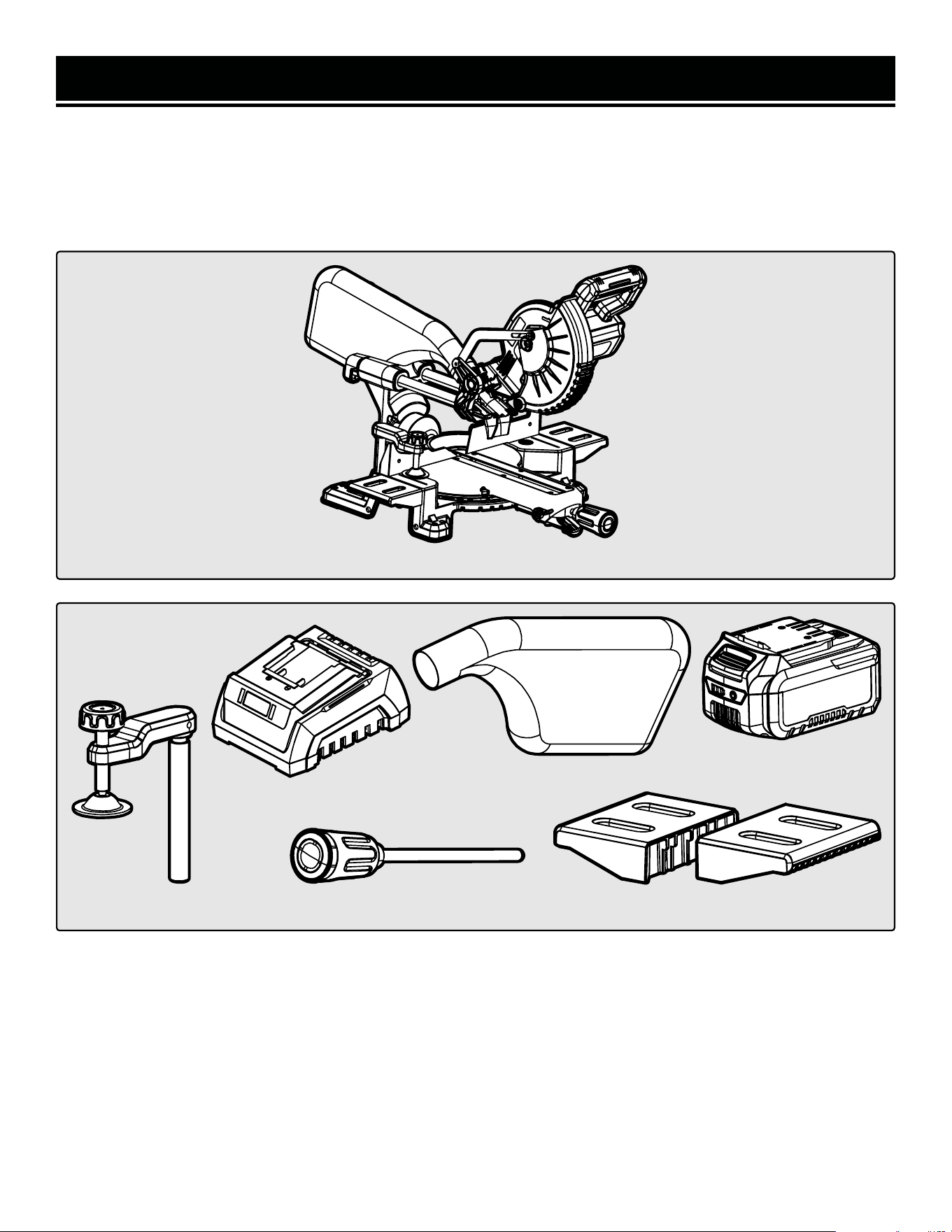
Components
NOTE: The 5mm/6mm hex wrench comes pre-installed on the miter saw.
*Only included with model number 20672.
11
Miter Saw
Accessories
*20V Battery (1)
Workpiece Clamp (1) Miter Lock Handle (1)
Dust Bag (1)
Left & Right Work Tables (2)
*20V Charger (1)
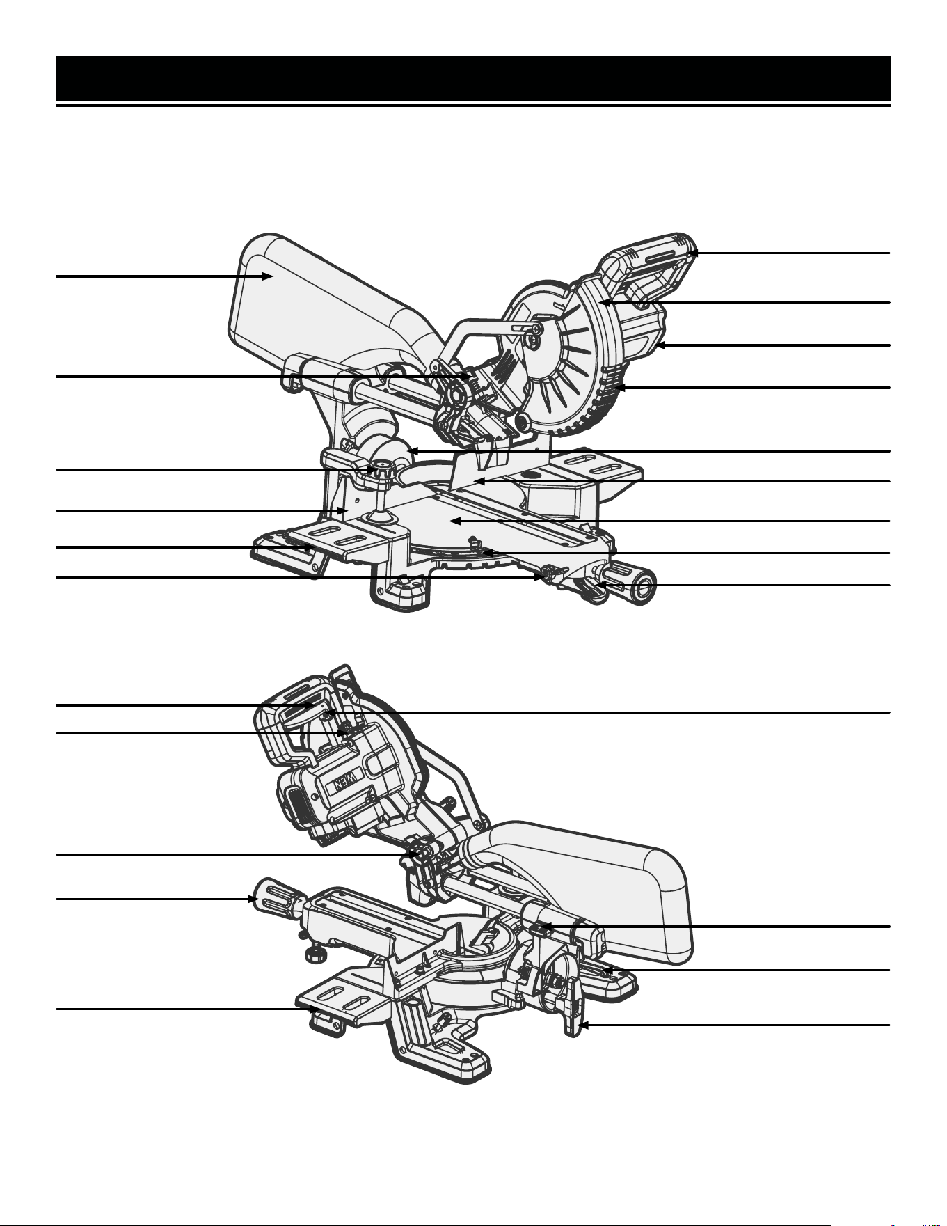
KNOW YOUR MITER SAW
TOOL PURPOSE
Easily make cuts at a variety of angles with your WEN Miter Saw. Refer to the following diagrams to become famil-
iarized with all the parts and controls of your miter saw. The components will be referred to later in the manual for
assembly and operation instructions.
12
Dust Bag
Operating Handle
Lower Blade Guard
Upper Blade Guard
Motor
Bevel Scale
Right Fence
Miter Angle Adjustment Lever
Wood Clamp
Left Table Extension
Left Fence
Depth Adjustment Knob
Right Table Extension
Miter Detent Override
Miter Scale
Work Table
Power Trigger
Power Trigger Lock
LED Power Switch
Hex Wrench Storage
Bevel Locking Knob
Lock Pin
Miter Lock Knob
Sliding Lock Knob
1
ASSEMBLY & ADJUSTMENTS
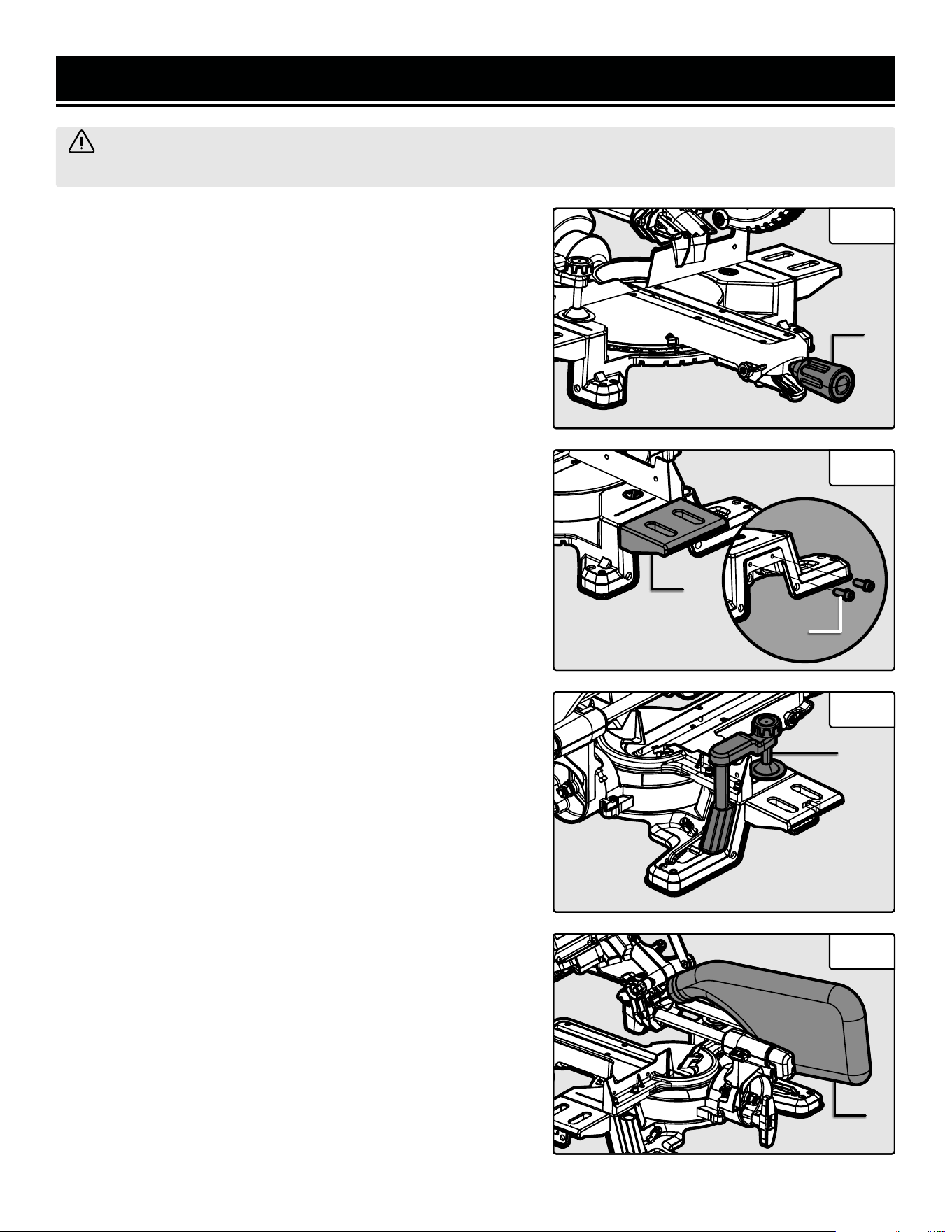
INSTALLING THE MITER LOCK KNOB
1. Screw the miter lock knob (Fig. 1 - 1) into the miter lock until
hand-tight. Do not overtighten; this could damage the miter lock.
INSTALLING THE TABLE EXTENSIONS
1. Remove the four M6x20 socket head cap screws (Fig. 2 - 1)
from the right and left sides of the miter saw base.
2. Align the left and right table extensions (Fig. 2 - 2) to the holes
on the sides of the miter saw base.
3. Secure the table extensions to the miter saw base using the
four M6x20 socket head cap screws that you removed in step 1.
Tighten using the included hex wrench.
4. Make sure that the table extensions are secure before beginning
operation.
INSTALLING THE CLAMP ASSEMBLY
The clamp can be mounted on the left or right side of the saw,
depending on the cutting task at hand.
1. Insert the clamp (Fig. 3 - 1) into the left or right clamp holder
behind the fence, as shown in Fig. 3.
2. Rotate the clamp knob to raise or lower the jaw of the clamp.
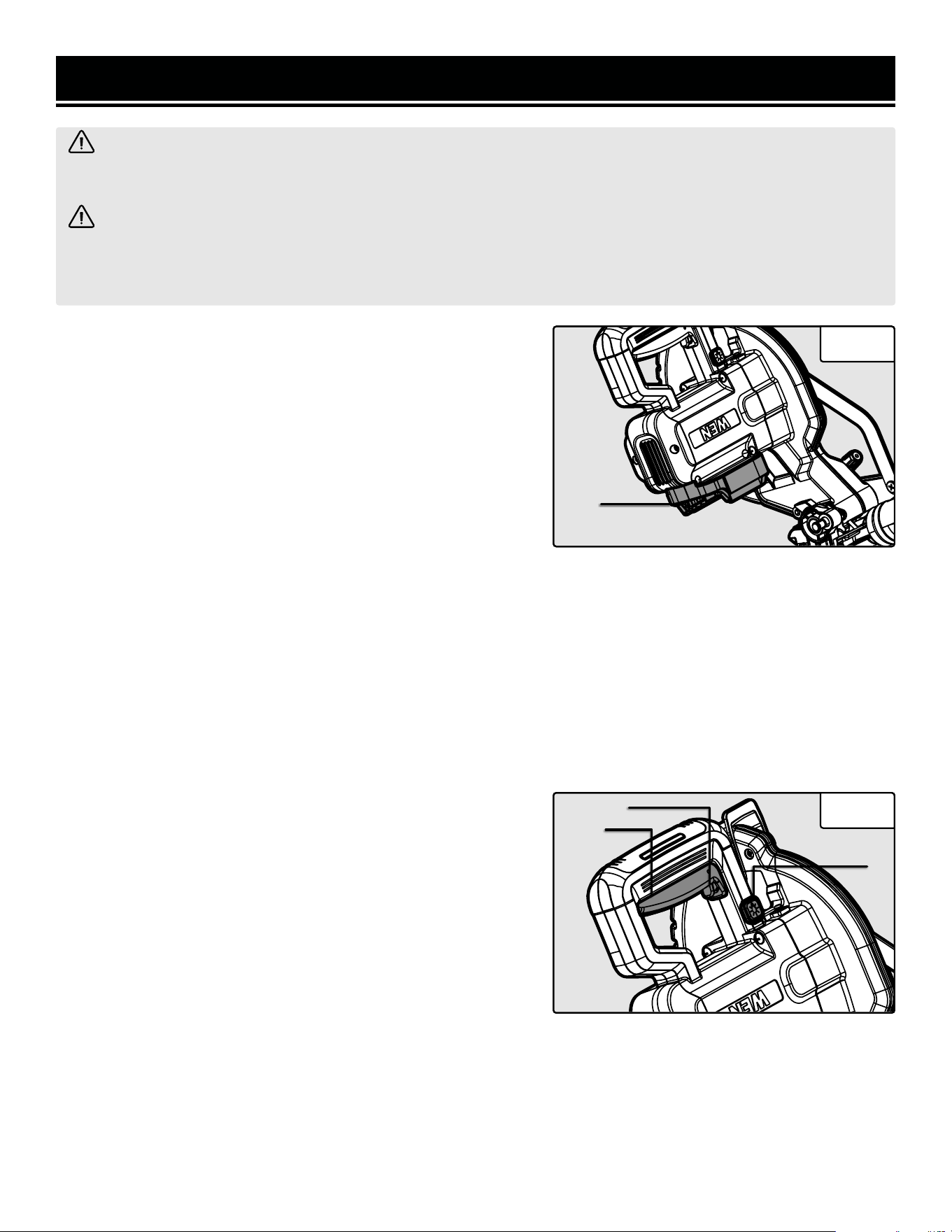
INSTALLING THE DUST COLLECTION BAG
The dust collection bag should be used at all times. Follow the
instructions below to install the bag:
1. Locate the dust port on the back of the miter saw.
2. Slide the mouth of the dust collection bag (Fig. 4 - 1) over the
dust port. Make sure that it is secured in place before beginning
operation.
3. Open the zipper on the bottom of the bag to empty it. For more
efficient operation, empty the dust bag when half full to allow for
better air flow through the bag.
NOTE: if you do not plan to use the dust collection bag, attach a
1.5-inch dust hose or connector to the dust port. The dust port’s
outer diameter is 1.46 in.; its inner diameter is 1.25 in. A hose
clamp (not included) may be required to secure the dust hose or
connector to the dust port.
WARNING! To avoid accidental startups, make sure that the tool is OFF and the battery is removed before
assembling the tool or making any adjustments.
Fig. 1
13
1
Fig. 2
Fig. 3
Fig. 4
1
2
1
14
ASSEMBLY & ADJUSTMENTS
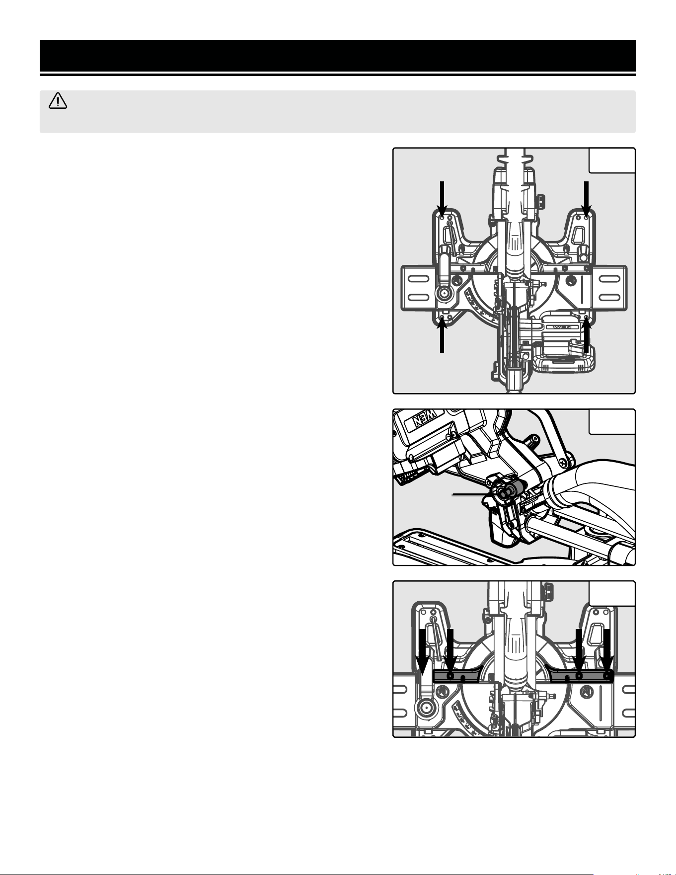
MOUNTING THE MITER SAW
The miter saw has four holes on the base for bench mounting (Fig.
5). Mount and fix the saw to a level, horizontal bench, worktable,
or miter saw stand (compatible with all WEN and most universal
miter saw stands) using four bolts and nuts (not included).
If desired, you can mount the saw to a piece of 1/2 inch or thicker
plywood which can then be clamped to your work bench or moved
to other jobsites and reclamped.
CAUTION! Make sure that the mounting surface is not warped.
Uneven surfaces can cause binding and inaccurate sawing.
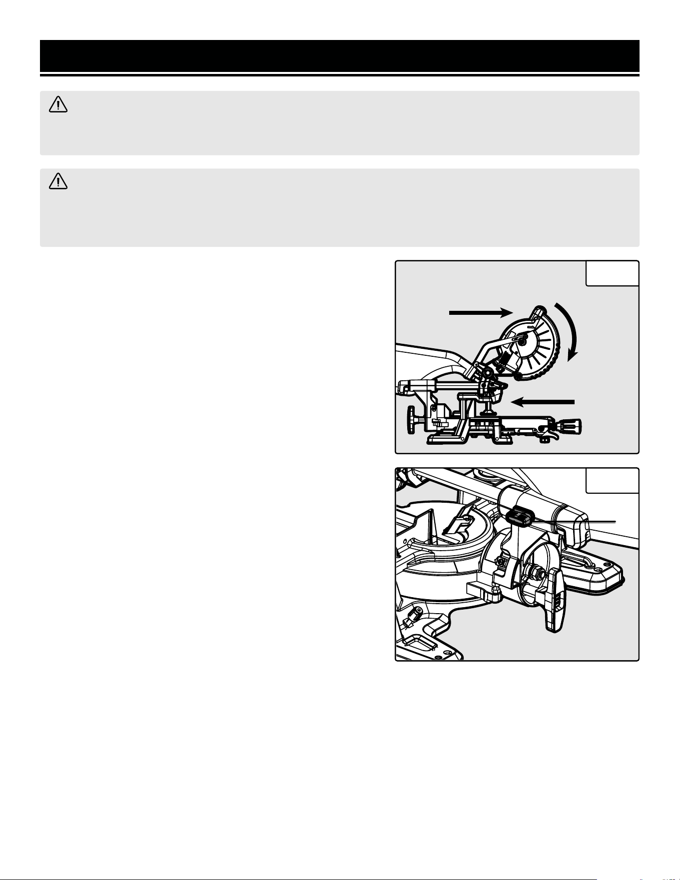
RAISING/LOWERING THE SAW ARM
The saw arm needs to be raised up before operation and locked
down for transporting and storage.
To raise the saw arm from the lower position:
1. Hold the operating handle and apply downward pressure. At the
same time, pull the locking pin (Fig. 6 - 1) out and slowly raise the
saw arm.
To lower the saw arm from the upper position:
1. Hold the operating handle and apply downward pressure. At the
same time, push the locking pin (Fig. 6 - 1) in to lock the saw arm
in place.
SQUARING THE BLADE TO THE FENCE
1. Make sure that the head is in the lowered position before squar-
ing the blade to the fence.
2. Set the bevel and miter angles to 0º. Tighten the adjustment
knobs. Slide the saw arm to the back and tighten the slide lock
knob.
3. Using a carpenter’s square (not included), place one edge
against the blade and the other edge against the fence.
NOTE: Make sure to rest the edge against the body of the blade
and not against the teeth of the blade.
4. Adjustments need to be made if the blade is not 90º to the fence.
5. Use the included hex wrench to loosen the four fence screws
that secure the fence to the table (Fig. 7).
WARNING! To avoid accidental startups, make sure that the tool is OFF and the battery is removed before
assembling the tool or making any adjustments.
Fig. 5
Fig. 6
1
Fig. 7
6. Rotate the fence left or right until the saw blade is perfectly perpendicular to the fence.
7. Tighten the four fence screws and double check that the fence and blade are square before beginning operation.
15
ASSEMBLY & ADJUSTMENTS
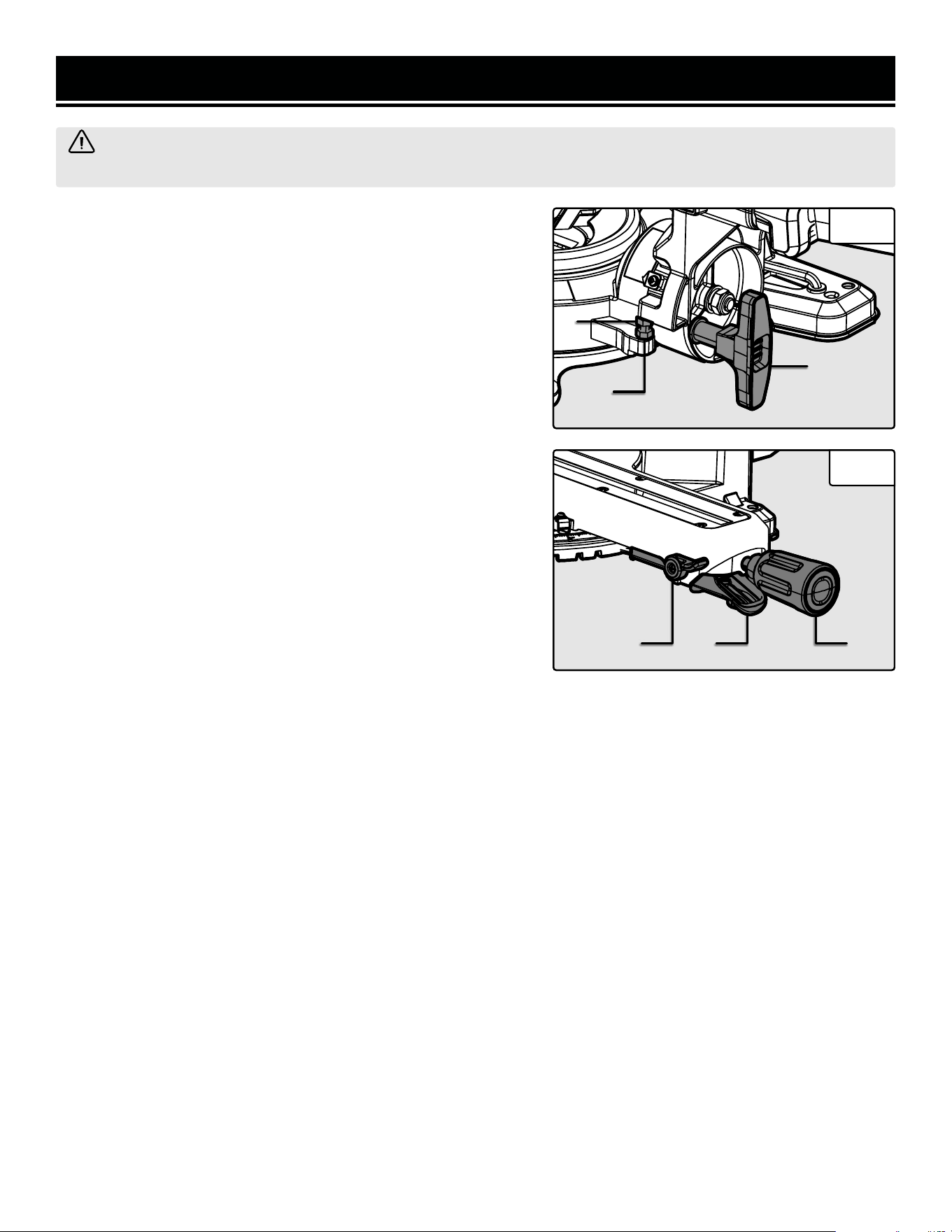
SQUARING THE BLADE TO THE TABLE
1. Make sure that the head is in the lowered position before squar-
ing the blade to the fence.
2. Set the bevel and miter angles to 0º. Tighten the adjustment
knobs. Slide the saw arm to the back and tighten the slide lock
knob.
3. Place a combination square (not included) on the table with the
heel of the square against the saw blade.
NOTE: Make sure to rest the square against the body of the blade
and not against the teeth of the blade.
4. Adjustments need to be made if the blade is not 90º to the table.
5. Loosen the bevel lock knob (Fig. 8 - 1).
6. Using a wrench (not included), loosen the positive stop nut (Fig.
8 - 2) and adjust the positive stop bolt (Fig. 8 - 3). Once the bolt is
in the desired position, tighten the positive stop nut.
7. Tighten the bevel lock knob and double check that the blade and
table are square before beginning operation.
8. Once everything has been squared, it may be necessary to loos-
en the indicator arrow screws and reset the indicator arrows to 0º.
ADJUSTING THE MITER ANGLE
1. Loosen the miter lock knob (Fig. 9 - 1) by twisting it counter-
clockwise.
2. Pull the miter angle adjustment lever (Fig. 9 - 2) and move the
table to the desired angle.
3. Release the miter angle adjustment lever and tighten the miter
lock knob to secure the table in place. Make sure that the table is
secure before beginning operation.
MITER DETENT OVERRIDE
The detent override (Fig. 9 - 3) allows for the table to move freely
to any desired angle, without stopping at the detents on the miter
scale. Loosen the miter lock knob, rotate the detent override back-
wards, and set the desired angle. Then tighten the miter lock knob.
To re-engage the detents, loosen the miter lock knob, rotate the
detent override forwards, and tighten the miter lock knob.
WARNING! To avoid accidental startups, make sure that the tool is OFF and the battery is removed before
assembling the tool or making any adjustments.
Fig. 8
2
1
Fig. 9
3 2 1
3
ASSEMBLY & ADJUSTMENTS
WARNING! To avoid accidental startups, make sure that the tool is OFF and the battery is removed before
assembling the tool or making any adjustments.
Fig. 10
1
2
16
Fig. 11
1
33.9º
45º
47º
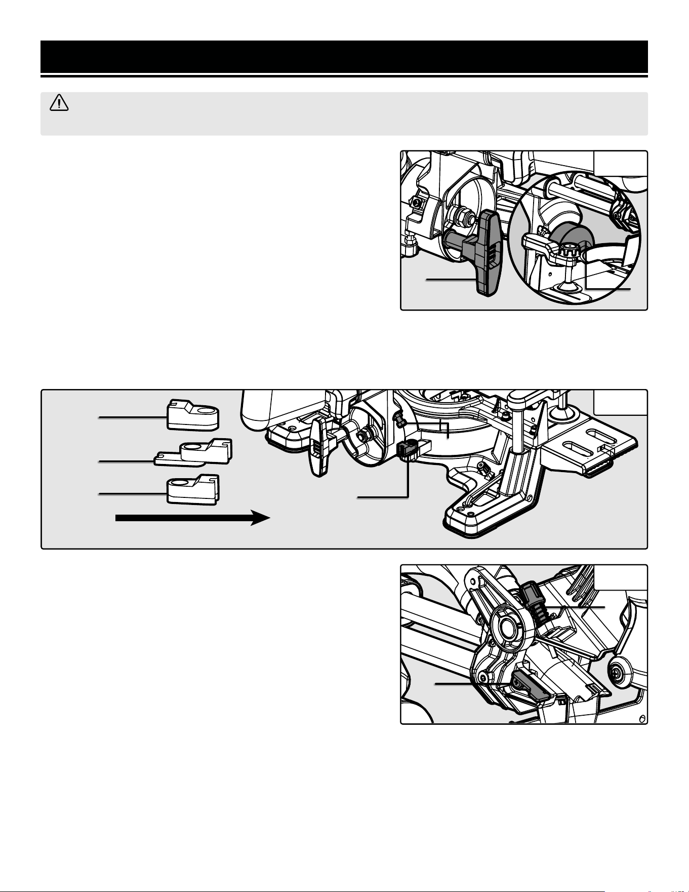
ADJUSTING THE CUTTING DEPTH
1. Raise the saw arm.
2. To use the depth stop, flip the depth stop lever (Fig. 12 - 1)
down. If you do not want to use the depth stop, flip the depth stop
lever up.
3. Rotate the depth stop knob (Fig. 12 - 2) to the desired depth.
When you lower the saw arm, the depth stop knob will come into
contact with the depth stop lever to stop the saw arm at the de-
sired depth.
Fig. 12
1
2
Front of the Saw
2
ADJUSTING THE BEVEL ANGLE
1. Loosen the bevel lock knob (Fig, 10 - 1).
2. Tilt the saw head to the desired angle on the bevel scale (Fig.
10 - 2).
3. Tighten the bevel lock knob.
USING THE BEVEL STOP BLOCKS
This saw is equipped with bevel stop blocks (Fig. 11 - 1) that allow
you to quickly and accurately set the bevel angle to 33.9º, 45º, or
47º. See Fig. 11 for the proper bevel stop block configurations.
Use the bevel positive stop bolt and nut (Fig. 11 - 2) to dial in the bevel stop blocks. Using a wrench (not included),
loosen the positive stop nut and adjust the positive stop bolt. Once the bolt is in the desired position, tighten the
positive stop nut.
17
OPERATION
SETTING UP THE WORKPIECE
Place the workpiece flat on the table with one edge securely against
the fence.
Warped Boards: If the board is warped, place the concave side
against the table. CAUTION: The board could break and jam the
blade if the convex side is placed against the table.
Long Boards: When cutting long workpieces, support the opposite
end of the material with a roller stand or work surface that is level
with the saw table.
Fig. 13
1
Fig. 14
1
2
3
SECURING THE WORKPIECE
Secure the workpiece with the clamp on the table whenever possible to prevent the material from moving during
cutting operation.
BEFORE OPERATION
• Check that the miter table does not rotate and the saw arm does not bevel.
• Check that the workpiece is fully supported, against the fence and securely clamped down.
• Check that you have the proper blade for the material you are cutting.
• Without turning the saw ON, perform a dry run of the cutting operation to check that nothing is obstructing the
path of the saw.
STARTING & STOPPING THE MITER SAW
1. Install the battery on the battery port (Fig. 13 - 1).
2. Press the power trigger lock (Fig. 14 - 1).
3. With the power trigger lock depressed, press the power trigger
(Fig. 14 - 2) to start the saw. Your saw is equipped with soft-start
technology, so the blade will take a moment to reach full speed.
Only start cutting after the blade has reached full speed.
4. To stop the saw, release the power trigger. The blade will spin
freely for a moment before the blade brake engages. Once opera-
tion has been completed, remove the battery from the battery port.
USING THE LED LIGHT
The LED light will automatically come on when the trigger is pulled, and will automatically turn off 15 seconds after
the trigger is released.
To turn the LED light on without starting the saw, press the LED light button (Fig. 14 - 3) once. The light will auto-
matically turn off 15 seconds later.
WARNING! Do not install the battery or turn the tool ON until it is fully assembled according to the instructions.
Read through and become familiarized with the following procedures of handling and adjusting your tool. Failure
to follow the safety instructions may result in serious personal injury.
WARNING! Before operating the miter saw, make sure to equip yourself with a dust mask, ear protection,
and safety glasses for protection from possible injuries. Tie back long hair and do not wear loose clothing or
jewelry. DO NOT look directly into the LED light; this can cause serious eye damage or blindness. Do not wear
gloves while operating the saw.
18
OPERATION
PERFORMING THE CUT
1. Install the battery. Turn the LED switch ON to see where your cut
will land on the material. CAUTION: DO NOT look into the LED light
or point it at any living thing.
2. Grip the operating handle firmly, press the power trigger lock,
and squeeze the power trigger to turn the saw ON.
3. Allow the blade to reach full speed. Make sure the workpiece is
held securely against the table and fence at all times. If the material
binds the blade, release the power trigger.
4. Slowly lower the blade into and through the workpiece as shown
in Fig. 15.
5. Release the power trigger and wait until the blade comes to a
full stop before raising it from the workpiece.
6. Remove the battery from the miter saw once operation has been
competed. Clean your work station and store the miter saw in a
safe location out of the reach of children.
SETTING UP THE SLIDING FUNCTION
The saw arm can be adjusted to different lengths using the slide
bar, and can slide back and forth when crosscutting.
For sliding cuts: Loosen the sliding bar lock knob (Fig. 16 - 1) and
slide the saw arm to desired position.
For non-sliding cuts and transportation: Tighten the sliding bar
lock knob for non-sliding operations and before transporting the
miter saw.
WARNING! Do not install the battery or turn the tool ON until it is fully assembled according to the instructions.
Read through and become familiarized with the following procedures of handling and adjusting your tool. Failure
to follow the safety instructions may result in serious personal injury.
WARNING! Before operating the miter saw, make sure to equip yourself with a dust mask, ear protection,
and safety glasses for protection from possible injuries. Tie back long hair and do not wear loose clothing or
jewelry. DO NOT look directly into the LED light; this can cause serious eye damage or blindness. Do not wear
gloves while operating the saw.
Fig. 15
1. Pull1. Pull
ForwardForward
2. Lower2. Lower
BladeBlade
3. Push Back 3. Push Back
to Cutto Cut
Fig. 16
For materials with a width under 3-1/2 inches (89mm): the sliding function isn’t necessary.
For materials with a width over 3-1/2 inches (89mm): the saw arm will need to slide to cut through the workpiece.
1
19
MAINTENANCE
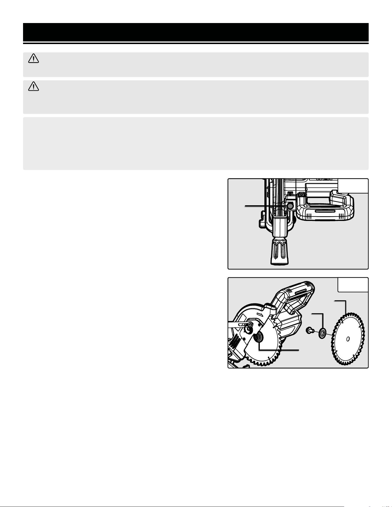
REPLACING THE SAW BLADE
DANGER! Never try to use a blade larger than the stated capacity
of the saw. Do not use a blade thicker than 1.9mm. It will prevent
the blade screw from properly securing the blade onto the spindle.
Install the suitable blade for your cutting operation.
1. Make sure that the tool is OFF and the battery pack is removed
before changing out the blade.
2. Press the spindle lock button (Fig. 17 - 1) and carefully rotate
the blade until it locks in place.
3. Using the included hex wrench, loosen the arbor bolt (Fig. 18 -
1) by turning it clockwise. Carefully remove the arbor bolt, outer
flange (Fig. 18 - 2), and blade (Fig. 18 - 3).
5. Install the new blade, outer flange, and arbor bolt. Tighten the
arbor bolt by turning it counterclockwise with the included hex
wrench. Make sure that the blade is secure before beginning op-
eration.
IMPORTANT: Make sure the blade’s rotation arrow points in the
same direction as the rotation arrow on the upper blade guard.
IMPORTANT: Carefully rotate the saw blade and make sure that
it does not wobble. Lower the saw arm and check that the blade
does not contact the throat plate, with the saw at 0° and 45° bevel
angles. Make sure the lower blade guard operates properly before
using the saw.
Fig. 17
Fig. 18
NOTE: Electric tools used on fiberglass material, wallboard, spackling compounds, or plaster are subject to ac-
celerated wear and possible premature failure because the fiberglass chips and grindings are highly abrasive to
bearings, brushes, commutators, etc. Consequently, we do not recommend using this tool for extended work on
these types of materials. However, if you do work with any of these materials, it is extremely important to clean
the tool using compressed air after operation.
WARNING! To avoid accidents, turn the tool OFF and remove the battery pack before cleaning, adjusting, or
performing any maintenance work.
WARNING! Any attempt to repair or replace electrical parts on this tool may be hazardous. Servicing of the
tool must be performed by a qualified technician. When servicing, use only identical WEN replacement parts.
Use of other parts may be hazardous or induce product failure.
1
1
2
3
MAINTENANCE
ROUTINE INSPECTION
Before each use, inspect the general condition of the tool. If any of these following conditions exist, do not use until
parts are replaced.
Check for:
• Loose hardware,
• Damaged battery pack,
• Cracked or broken parts, and
• Any other condition that may affect its safe operation
CLEANING & STORAGE
1. Keep the ventilation openings free from dust and debris to prevent the motor from overheating.
2. Wipe the tool surfaces clean with a damp cloth and mild soap. Make sure water does not get into the tool.
WARNING! To avoid accidents, turn OFF and remove the battery pack from the charger and the charger from
the outlet before cleaning, adjusting, or performing any maintenance work.
WARNING! Any attempt to repair or replace electrical parts on this tool may be hazardous. Servicing of the
tool must be performed by a qualified technician. When servicing, use only identical WEN replacement parts.
Use of other parts may be hazardous or induce product failure.
CAUTION: Most plastics are susceptible to damage from various types of commercial solvents. Do not use any
solvents or cleaning products that could damage the plastic parts. Some of these include but are not limited to:
gasoline, carbon tetrachloride, chlorinated cleaning solvents, and household detergents that contain ammonia.
3. Allow the tool to cool before storing it. Store the tool in a clean and dry place away from the reach of children.
PRODUCT DISPOSAL
Used power tools should not be disposed of together with household waste. This product contains electronic com-
ponents that should be recycled. Please take this product to your local recycling facility for responsible disposal and
to minimize its environmental impact.
20
Fig. 19
1
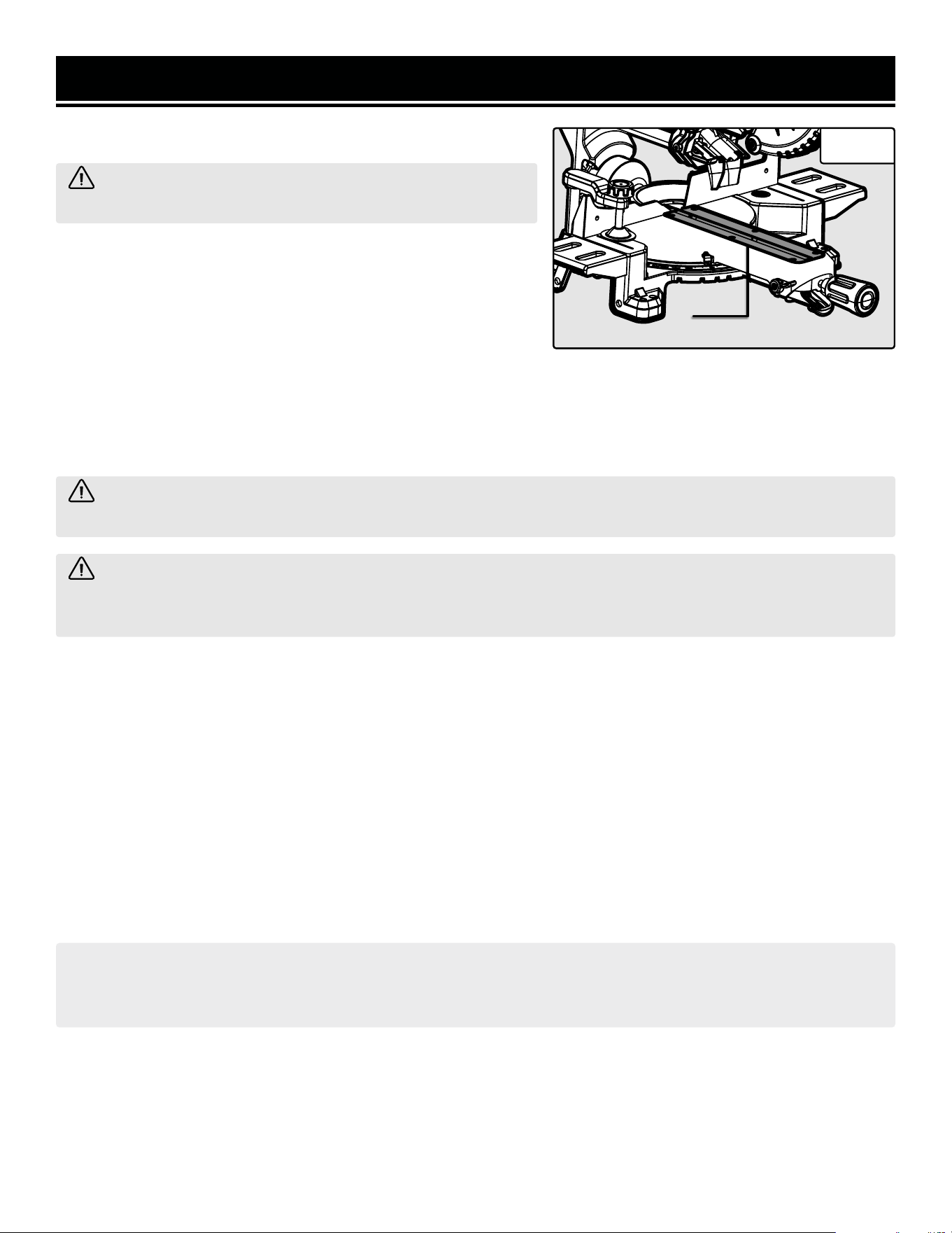
REPLACING THE SAW THROAT PLATE
WARNING! Never operate the miter saw without a throat
plate installed.
1. Make sure that the tool is OFF and the battery pack is removed
before replacing the throat plate.
2. Remove the six mounting screws securing the throat plate (Fig.
19 - 1) to the table and lift the plate from the saw.
3. Install the new throat plate using the six mounting screws that
you removed previously. DO NOT overtighten the screws. Over-
tightening the screws can cause the throat plate to bend. Replace-
ment throat plates can be purchased from wenproducts.com (part
no. 20672-6014).
EXPLODED VIEW & PARTS LIST
21
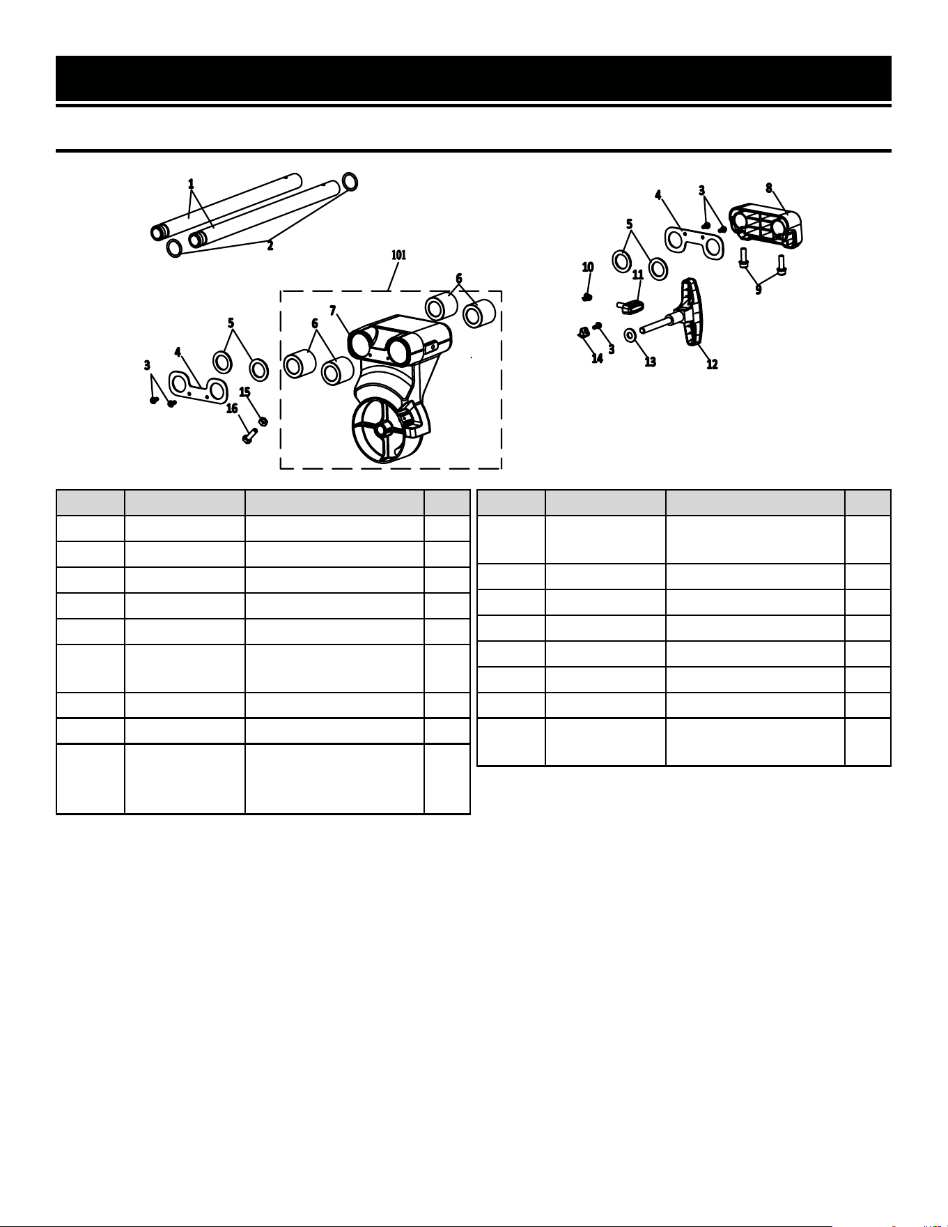
FIG. 1 - BEVEL ARM
No. Part No. Description Qty.
1 20672-1001 Rail 2
2 20672-1002 Bearing Cap 2
3 20672-1003 Torx Screw, M4x10 5
4 20672-1004 Bevel Arm Cover 2
5 20672-1005 Felt Washer 4
6 20672-1006
Linear Rail Bearing,
32x20x30
4
7 20672-1007 Bevel Arm 1
8 20672-1008 Rail Support Bracket 1
9 20672-1009
Socket Head Cap
Screw with Washer,
M6x20
2
No. Part No. Description Qty.
10 20672-1010
Sliding Lock Knob
Spring
1
11 20672-1011 Sliding Lock Knob 1
12 20672-1012 Bevel Knob 1
13 20672-1013 Washer, 8x18 1
14 20672-1014 Bevel Scale 1
15 20672-1015 Nut, M6 1
16 20672-1016 Hex Bolt, M6x20 1
101
20672-
101ASM
Bevel Arm Assembly 1
EXPLODED VIEW & PARTS LIST
No. Part No. Description Qty.
1 20672-2001 Pivot Pin 1
2 20672-2002 Main Spring Spacer 1
3 20672-2003 Head Pivot Arm 1
4 20672-2004 Pivot Spring 1
5 20672-2005
Phillips Screw with
Washer, M4x10
4
6 20672-2006 Dust Port 1
7 20672-2007 Head Locking Pin 1
8 20672-2008 O-Ring, 10x1.9 1
9 20672-2009 E-clip, 8mm 1
10 20672-2010 Set Screw, M6x10 2
11 20672-2011 Inner Dust Port 1
12 20672-2012 Chip Deflector 1
13 20672-2013 Flip Arm 1
14 20672-2014 Wavy Washer, 7mm 1
15 20672-2015
Rail Locking Screw,
M5x8
1
FIG. 2 - HEAD PIVOTING ASSEMBLY
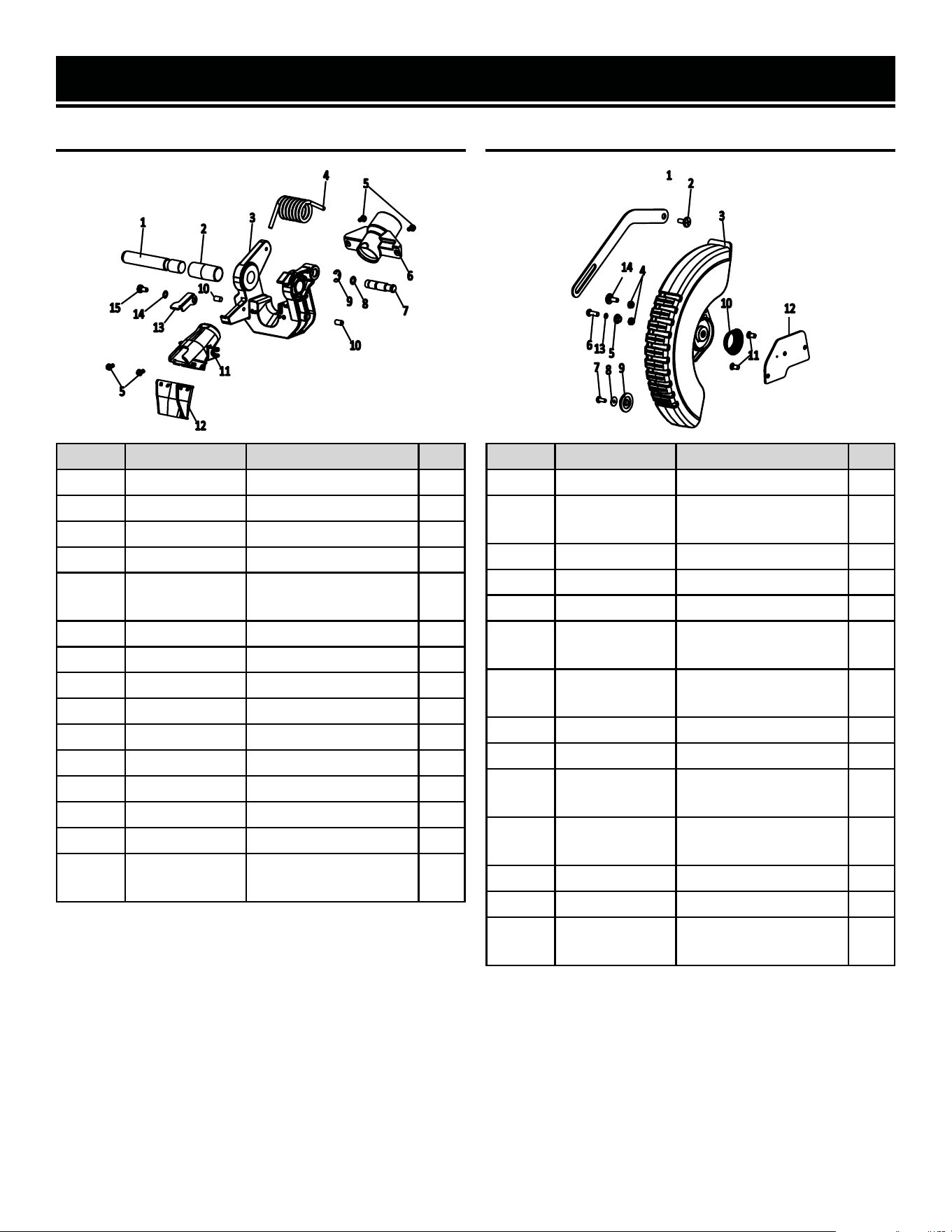
No. Part No. Description Qty.
1 20672-3001 Linkage Arm 1
2 20672-3002
Linkage Arm Shoul-
der Screw, M5x10
2
3 20672-3003 Blade Guard 1
4 20672-3004 Lock Nut, M5 2
5 20672-3005 Guard Center Sleeve 1
6 20672-3006
Phillips Screw,
M5x16
1
7 20672-3007
PoziDriv Self-Tapping
Screw, ST4x6
1
8 20672-3008 Washer, 4x12x1 1
9 20672-3009 Blade Guard Wheel 1
10 20672-3010
Blade Guard Torsion
Spring
1
11 20672-3011
Phillips Screw,
M5x10
2
12 20672-3012 Guard Support Plate 1
13 20672-3013 Spring Washer, 5mm 1
14 20672-3014
Rail Locking Screw,
M5x8
1
FIG. 3 - LOWER BLADE GUARD
22
EXPLODED VIEW & PARTS LIST
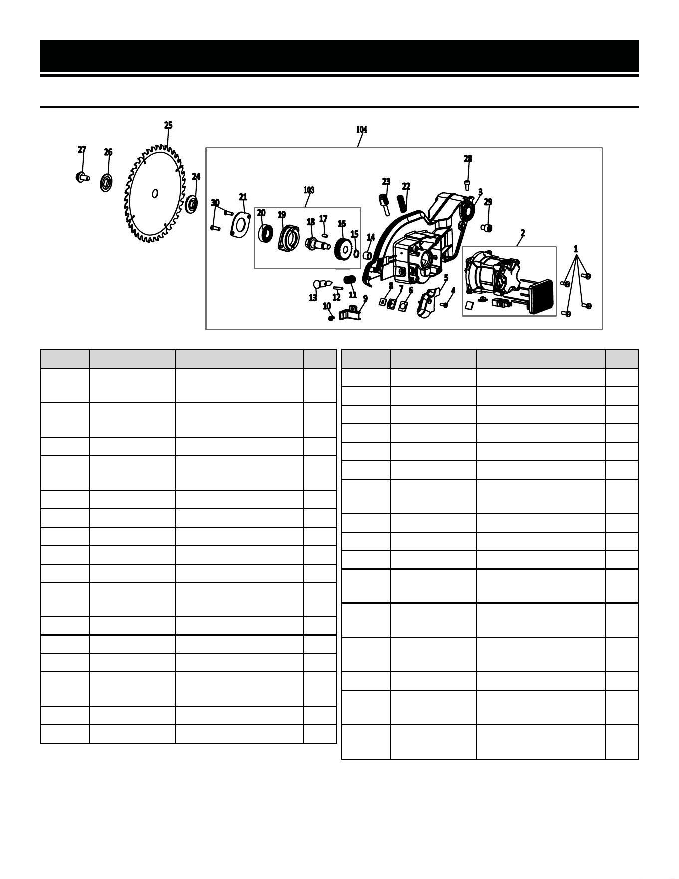
FIG. 4 - BLADE & MOTOR ASSEMBLY
No. Part No. Description Qty.
1 20672-4001
Phillips Screw with
Washer, M5x14
4
2 20672-4002
6035 Brushless Motor
& PCB
1
3 20672-4003 Head Housing 1
4 20672-4004
Phillips Screw with
Washer, M4x10
1
5 20672-4005 LED Frame Cover 1
6 20672-4006 Clear Panel 1
7 20672-4007 LED Cover 1
8 20672-4008 LED Gasket 1
9 20672-4009 Wire Cover 1
10 20672-4010
Phillips Screw with
Washer, M4x10
1
11 20672-4011 Arbor Spring 1
12 20672-4012 Roller Pin 1
13 20672-4013 Arbor Lock 1
14 20672-4014
Needle Bearing,
HK0910
1
15 20672-4015 Circlip, 12mm 1
16 20672-4016 Gear 1
No. Part No. Description Qty.
17 20672-4017 Key, 4x4x10 1
18 20672-4018 Arbor 1
19 20672-4019 Gearbox Cover 1
20 20672-4020 Ball Bearing, 6002 1
21 20672-4021 Bearing Cover 1
22 20672-4022 Limiting Screw Spring 1
23 20672-4023
Limiting Screw,
M6x35
1
24 20672-4024 Inner Flange 1
25 BL0740 Blade 1
26 20672-4026 Outer Flange 1
27 20672-4027
Socket Cap Screw,
M8x16, Left-Handed
1
28 20672-4028
Socket Cap Screw,
M5x14
1
29 20672-4029
Socket Cap Screw,
M8x12
1
30 20672-4030 Phillips Screw, M5x16 2
103
20672-
103ASM
Gearbox Assembly 1
104
20672-
104ASM
Head Assembly 1
23
24
EXPLODED VIEW & PARTS LIST
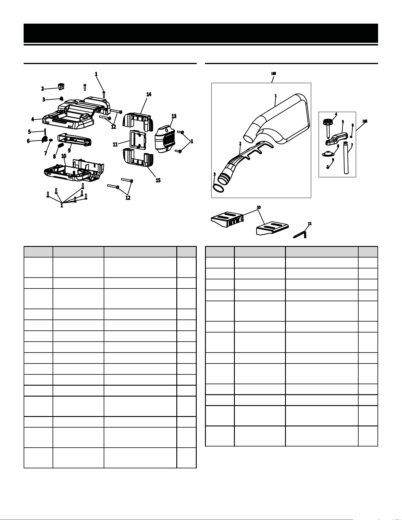
No. Part No. Description Qty.
1 20672-5001
PoziDriv Self-Tapping
Screw, ST4x16
10
2 20672-5002 LED Switch 1
3 20672-5003
Brake Lever Reset
Spring
1
4 20672-5004 Upper Handle 1
5 20672-5005 Trigger Lock Pin 1
6 20672-5006 Trigger Lock 1
7 20672-5007 Trigger Lock Spring 1
8 20672-5008 Trigger Spring 1
9 20672-5009 Main Trigger 1
10 20672-5010 Lower Handle 1
11 20672-5011 Battery Terminal 1
12 20672-5012
PoziDriv Screw,
M5x35
4
13 20672-5013 Motor End Cap 1
14 20672-5014
Upper Battery
Terminal Housing
1
15 20672-5015
Lower Battery
Terminal Housing
1
FIG. 5 - HANDLE
No. Part No. Description Qty.
1 20672-7001 Dust Bag 1
2 20672-7002 Dust Bag Frame 1
3 20672-7003 Clamp, 7.6x200 1
4 20672-7004 Hold-down Clamp 1
5 20672-7005
Hold-down Clamp
Arm
1
6 20672-7006 Set Screw, M6x6 1
7 20672-7007
Hold-down Clamp
Rod
1
8 20672-7008 Clamp Plate 1
9 20672-7009
Phillips Screw with
Washer, M4x10
1
10 20672-7010 Table Extension 2
11 20672-7011 Hex Key, M6 & M5 1
105
20672-
105ASM
Dust Bag Assembly 1
106
20672-
106ASM
Hold-down Clamp
Assembly
1
FIG. 6 - ACCESSORIES
25
EXPLODED VIEW & PARTS LIST
FIG. 7 - TABLE

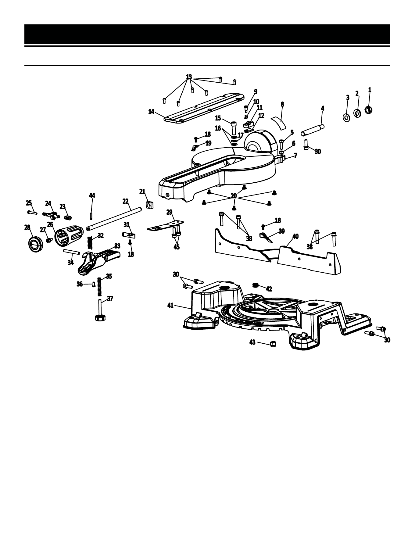
EXPLODED VIEW & PARTS LIST
FIG. 7 - TABLE
No. Part No. Description Qty.
1 20672-6001 Nut, M10 1
2 20672-6002 Spring Washer, 10mm 1
3 20672-6003 Washer, 10mm 1
4 20672-6004 Bevel Pin 1
5 20672-6005 Hex Bolt, M6x20 1
6 20672-6006 Hex Nut, M6 1
7 20672-6007 Table 1
8 20672-6008 Bevel Label 1
9 20672-6009
Stop-block Shoulder
Screw, M4x6.8
1
10 20672-6010 Stop-block Spring 1
11 20672-6011 33.9° Stop Block 1
12 20672-6012 45° Stop Block 1
13 20672-6013 Phillips Screw, M4x10 6
14 20672-6014 Throat Plate 1
15 20672-6015
Pan Socket Head
Screw, M8x25
1
16 20672-6016 Washer, 8mm 2
17 20672-6017 Wavy Washer, 8mm 1
18 20672-6018
Phillips Screw with
Washer, M4x10
3
19 20672-6019 Miter Pointer 1
20 20672-6020 Table Friction Block 6
21 20672-6021 Square Nut, M10 1
22 20672-6022 Miter Lock Rod 1
23 20672-6023 Detent Bypass Cam 1
24 20672-6024 Detent Bypass Lever 1
25 20672-6025 Torx Screw, ST4x25 1
26 20672-6026 Miter Locking Knob 1
No. Part No. Description Qty.
27 20672-6027
Socket Head Cap
Screw with Washer,
M5x16
1
28 20672-6028
Miter Locking Knob
Cap
1
29 20672-6029 Table Positioning Plate 1
30 20672-6030
Socket Head Cap
Screw with Washer,
M6x20
7
31 20672-6031 Detent Locking Plate 1
32 20672-6032 Miter Lever Spring 1
33 20672-6033 Miter Lever 1
34 20672-6034 Miter Lever Pin 1
35 20672-6035
Secondary Foot
Spring
1
36 20672-6036
PoziDriv Self-tapping
Screw, ST4x10
1
37 20672-6037 Secondary Foot 1
38 20672-6038
Socket Head Cap
Screw with Washer,
M6x30
4
39 20672-6039 Fence Locator Block 1
40 20672-6040 Fence 1
41 20672-6041 Base 1
42 20672-6042 Wrench Grommet 1
43 20672-6043 Lock Nut, M8 1
44 20672-6044 Roller Pin, 4x16 1
45 20672-6045
Socket Head Cap
Screw with Washer,
M8x20
2
26

WARRANTY STATEMENT
WEN Products is committed to building tools that are dependable for years. Our warranties are consistent with this
commitment and our dedication to qualit
y.
LIMITED WARRANTY OF WEN PRODUCTS FOR HOME USE
GRE
AT LAKES TECHNOLOGIES, LLC (“Seller”) warrants to the original purchaser only, that all WEN
consumer
power tools will be free from defects in material or workmanship during personal use for a period of two (2) years
used
for professional or commercial use. Purchaser has 30 days from the date of purchase to report missing or
damaged parts.
SELLER’S
SOLE OBLIGATION AND YOUR EXCLUSIVE REMEDY under this Limited Warranty and, to the extent per-
mitted
by law, any warranty or condition implied by law, shall be the replacement of parts, without charge, which a
re
defective
in material or workmanship and which have not been subjected to misuse, alteration, careless handling,
misrepai
r, abuse, neglect, normal wear and tear,
improper maintenance, or other conditions adversely affecting the
Product
or the component of the Product, whether by accident or intentionally, by persons other than Seller. To
make
a claim under this Limited Warranty, you must make sure to keep a copy of your proof of purchase that
clearly
-
dor
of Great Lakes Technologies, LLC. Purchasing through third party vendors, including but not limited to garage
sales,
pawn shops, resale shops, or any other secondhand merchant, voids the warranty included with this
product.
Contact [email protected] or 1-800-232-1195 with the following information to make arrangements:
your
shipping address, phone number, serial number, required part numbers, and proof of purchase. Damaged
or
defective parts and products may need to be sent to WEN before the replacements can be shipped out.
-
turning
a product for warranty service, the shipping charges must be prepaid by the purchaser. The product
must
be
shipped in its original container (or an equivalent), properly packed to withstand the hazards of shipment. The
product
must be fully insured with a copy of the proof of purchase enclosed. There must also be a description of
the
will be returned and shipped back to the pur
chaser at no charge for addresses within the contiguous United States.
THIS
LIMITED WARRANTY DOES NOT APPLY TO ITEMS THAT WEAR OUT FROM REGULAR USAGE OVER TIME,
INCLUDING
BELTS, BRUSHES, BLADES, BATTERIES, ETC. ANY IMPLIED WARRANTIES SHALL BE LIMITED IN
DUR
ATION TO TWO (2) YEARS FROM DATE OF PURCHASE. SOME STATES IN THE U.S. AND SOME CANADIAN
PROVINCES
DO NOT ALLOW LIMITATIONS ON HOW LONG AN IMPLIED WARRANTY LASTS, SO THE ABOVE LIMI-
TAT
ION MAY NOT APPLY TO YOU.
IN
NO EVENT SHALL SELLER BE LIABLE FOR ANY INCIDENTAL OR CONSEQUENTIAL DAMAGES (INCLUDING
BUT
NOT LIMITED TO LIABILITY FOR LOSS OF PROFITS) ARISING FROM THE SALE OR USE OF THIS PRODUCT.
SOME ST
ATES IN THE U.S. AND SOME CANADIAN PROVINCES DO NOT ALLOW THE EXCLUSION OR LIMITAT
ION
OF
INCIDENTAL OR CONSEQUENTIAL DAMAGES, SO THE ABOVE LIMITATION OR EXCLUSION MAY NOT APPLY
TO YOU.
THIS
LIMITED WARRANTY GIVES YOU SPECIFIC LEGAL RIGHTS, AND YOU MAY ALSO HAVE OTHER RIGHTS
WHICH
VARY FROM STATE TO STATE IN THE U.S., PROVINCE TO PROVINCE IN CANADA AND FROM COUNTRY
TO COUNT
RY.
THIS
LIMITED WARRANTY APPLIES ONLY TO ITEMS SOLD WITHIN THE UNITED STATES OF AMERICA, CANA-
DA
AND THE COMMONWEALTH OF PUERTO RICO. FOR WARRANTY COVERAGE WITHIN OTHER
COUNTRIES,
CONT
ACT THE WEN CUSTOMER SUPPORT LINE. FOR WARRANTY PARTS OR PRODUCTS REPAIRED UNDER
W
ARRANTY SHIPPING TO ADDRESSES OUTSIDE OF THE CONTIGUOUS UNITED STATES, ADDITIONAL
SHIPPING
CHARGES MAY APPLY.
27

V. 2025.01.15
THANKS FOR
REMEMBERING