homeowner’s manual, installation, and
tech support guide
electric tankless
water heater
Page 2
table of contents
safety precautions
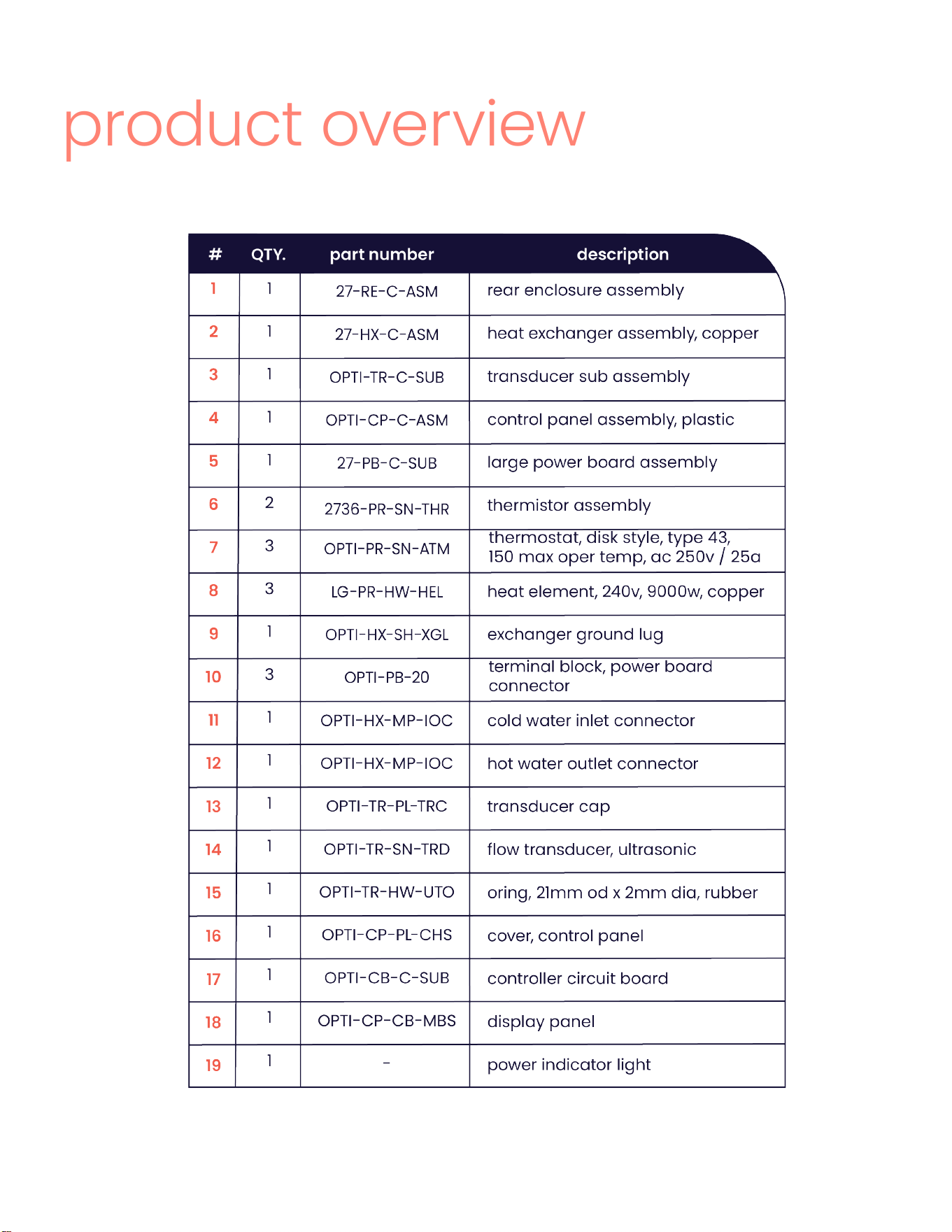
product overview
before installing
mounting
plumbing installation
electrical installation
powering up
best practices
troubleshooting
warranty
spanish version
3
4-6
7-8
8-9
10-11
12-15
16-17
17-18
19-20
21-22
23-41
Page 3
safety precautions
READ ALL INSTRUCTIONS BEFORE USING
DANGER - Injury. Please read and follow these instructions. Failure to follow these instruc-
tions could result in serious personal injury or death.
DAMAGE TO THE APPLIANCE AND THE ENVIRONMENT. The appliance must be installed by
a licensed electrician and plumber. The installation must comply with all national, state,
and local plumbing and electric codes. Service of the appliance must be performed by
qualied service technicians.
Conforms to UL STD. 499 & NSF/ANSI/CAN STD. 372 Certied to CSA STD. C22.2 NO. 64
DANGER - Electrocution. Before proceeding with any installation, adjustment, alteration, or
service of this appliance, all circuit breakers and disconnect switches servicing the appli-
ance must be turned off. Never remove the appliance’s cover unless the electricity ser-
vicing the appliance is turned off. Failure to do so could result in personal injury or death.
The appliance must be properly grounded. Failure to electrically ground the product could
result in serious personal injury or death.
DANGER - Burns. Water temperatures over 125 °F (52 °C) can cause severe burns instantly
or death from scalding. Hot water scalding potential exists if the thermostat on the ap-
pliance is set too high. Households with small children, disabled or elderly persons may
require that the thermostat be set at 113 °F (45 °C) or lower to prevent possible injury from
hot water.
WARNING - Injury. Where children or persons with limited physical, sensory, or mental
capabilities are to be allowed to control this appliance, ensure that this will only happen
under supervision or after appropriate instructions by a person responsible for their safety.
Children should be supervised to ensure that they never play with the appliance.
Page 4
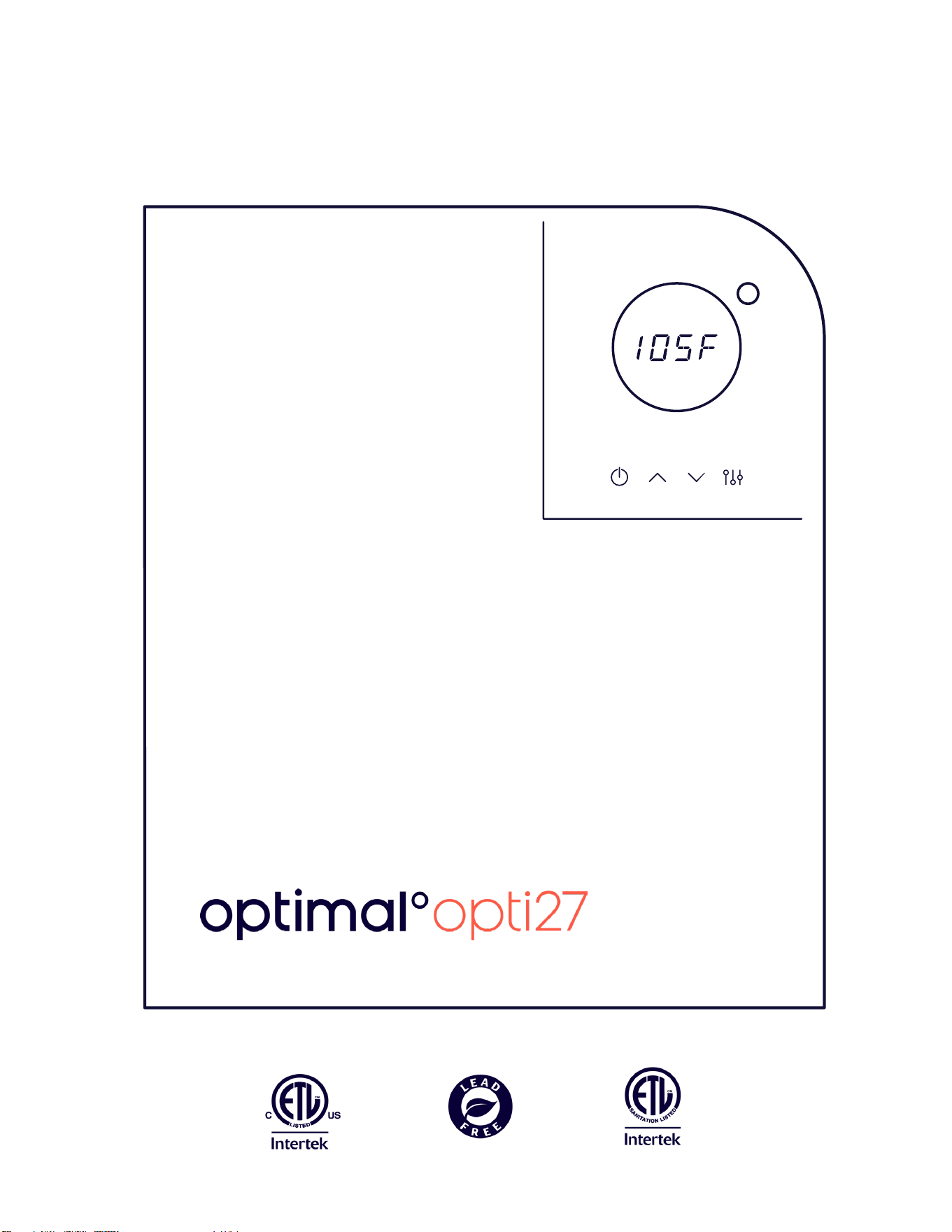
product overview
Page 5
1
2
2
3
3
4
5
6
77
8 8
9
11
12
13
14
14
15
17
16
18
10
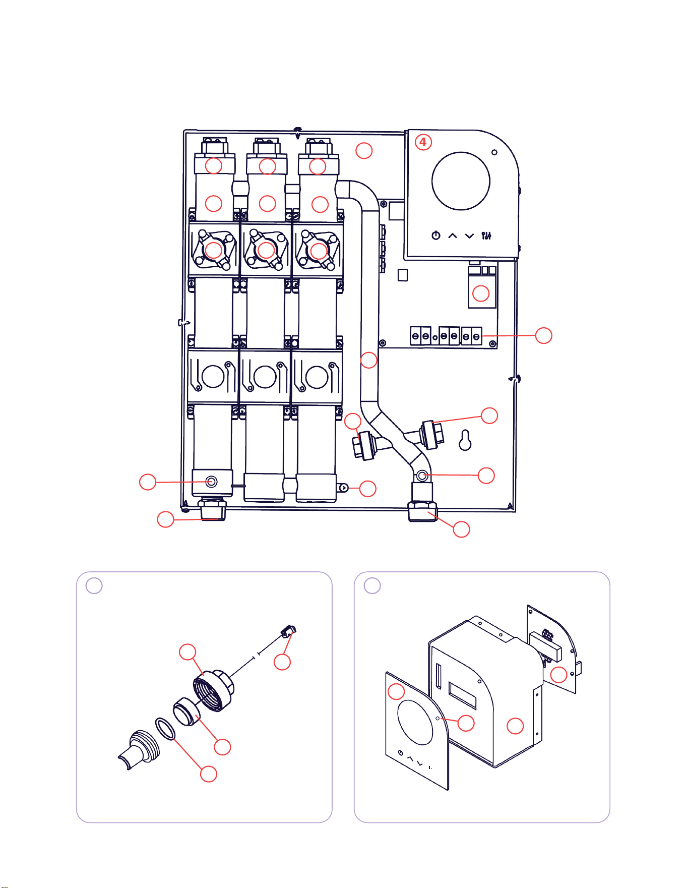
product overview - parts
4
3
*
* *
*
19
6
2
7
2
8
Page 6
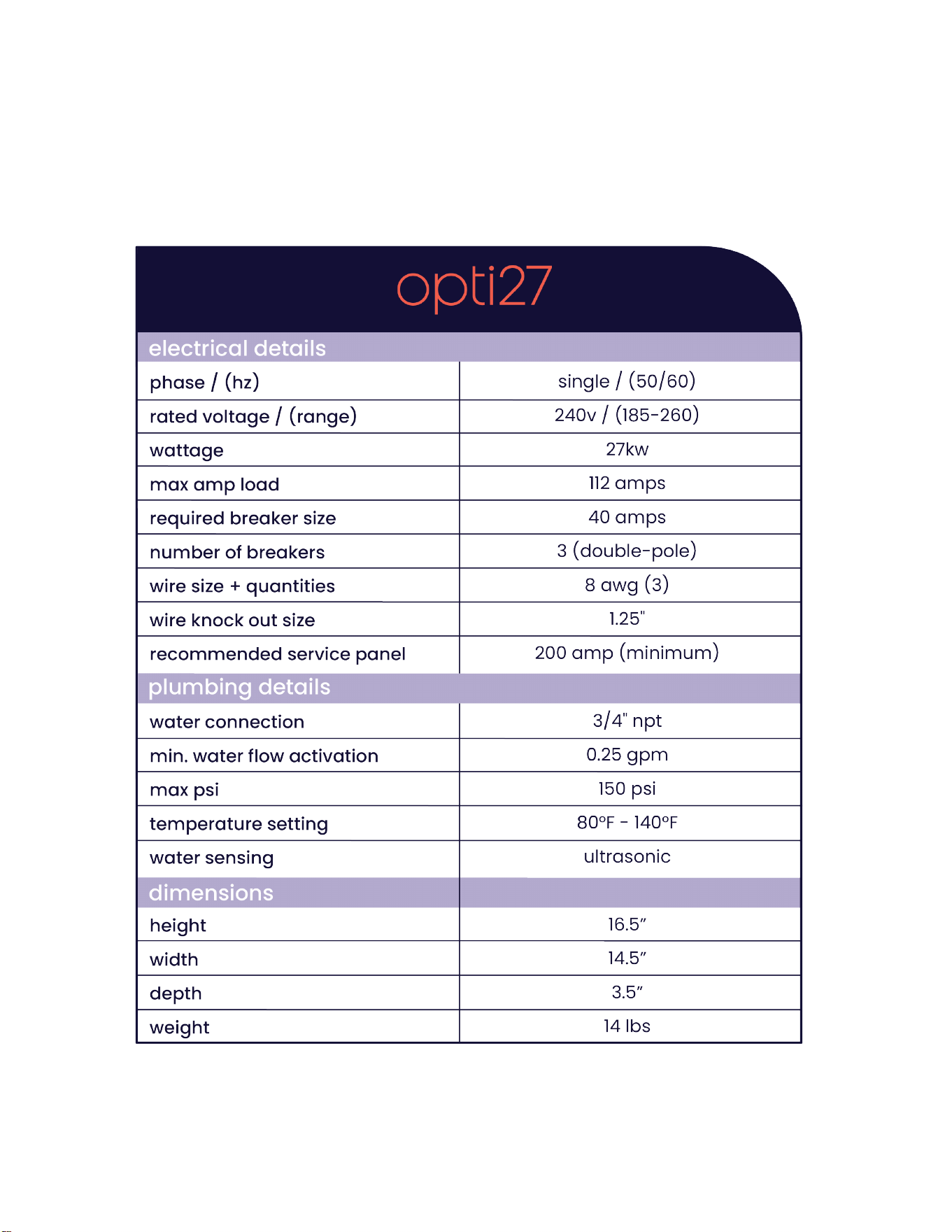
product overview - technical data
Page 7
before installing
Please read these instructions thoroughly and completely prior to installation and use.
Failure to follow instructions could cause property damage, serious personal injury, or
death. By installing this product, you acknowledge the terms of the manufacturer’s
warranty included in your product. Contact us if you have any questions about the
warranty or the product. Our dedicated support team is standing by, ready to assist.
You can also nd more information and submit a case form on our website.
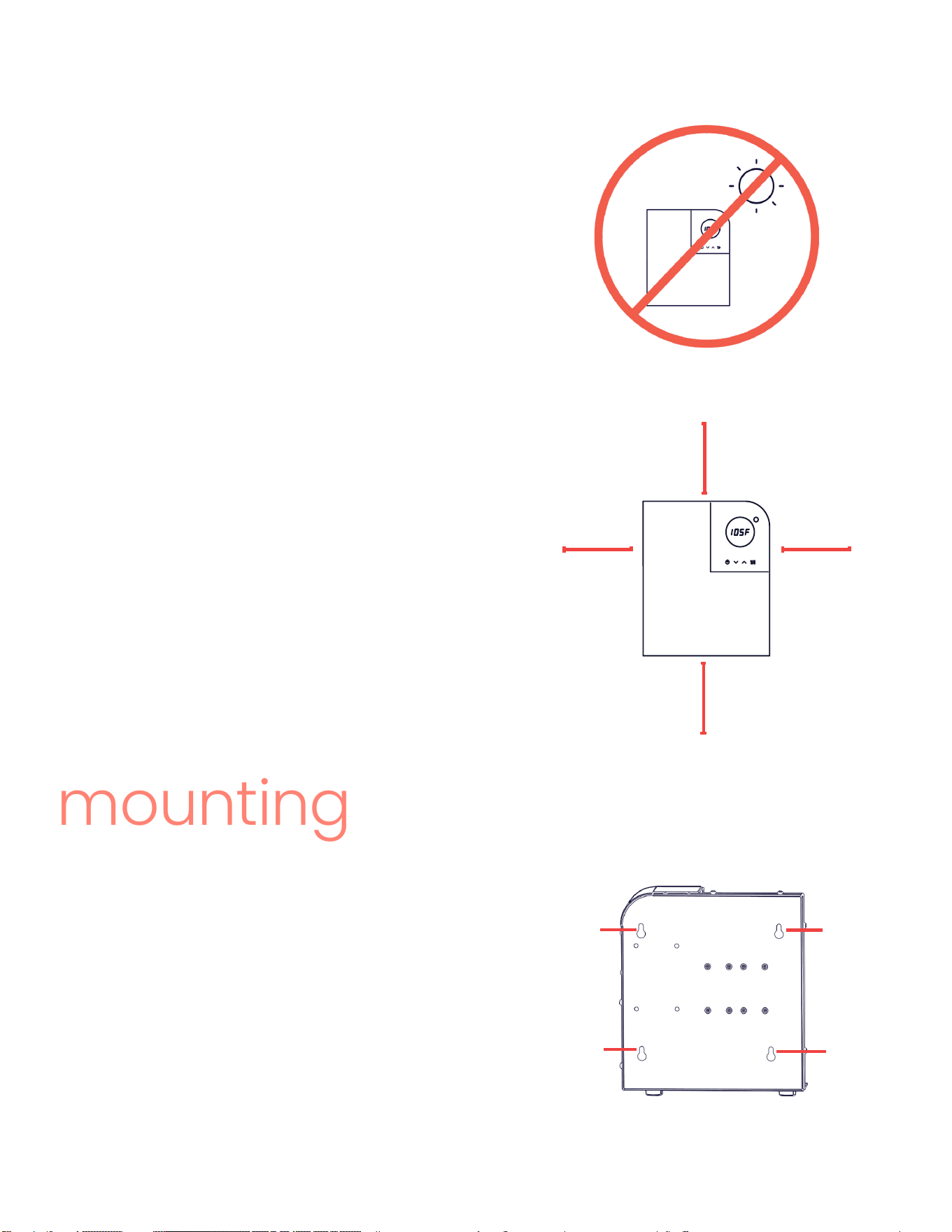
SAFETY PRECAUTIONS - MOUNTING
DO NOT install this product in a location where it may be subjected to freezing temperatures. If
the water inside your tankless water heater freezes, it can cause severe and permanent dam-
age that is not covered under your warranty.
DO NOT install the water heater in a location that is difcult to access.
DO NOT install product within reach of children so they are unable to tamper with the temper-
ature controls or injure themselves by touching the hot water outlet line. The outlet water line
may get extremely hot.
This product does NOT require venting.
Avoid installing your tankless water heater in a location prone to excessive humidity, moisture,
or dust or in an area where it may be splashed with water or other liquids.
DO NOT install underwater pipes or air conditioning lines that might leak or condense moisture
that could then drip onto the heater.
DO NOT install above outlets or electrical boxes.
CAUTION – COMBUSTIBLE MATERIALS should be kept at least 24 inches away from your water
heater and the hot water outlet line.
386-OPTIMAL (386-678-4625)
itsoptimal.com
Page 8
where to install
Whether you are using your water heater for
whole-home distribution or point of use, the three
main considerations for the install location are:
12.5”
6”
12.5”
6”
Access to an electrical panel
Access to a plumbing connection
Mounting surface and clearance
This product is designed to be installed indoors.
Mounting outside will void the warranty.
mounting
REAR VIEW
mounting
hole
mounting
hole
mounting
hole
mounting
hole
Your Optimal° tankless water heater has
four 1/2” mounting holes located on the
back. For ease of installation and servicing,
we recommend this product is installed in
an upright position with the inlet and out-
let water connections at the bottom of the
product. If your install requires the product
to be mounted on its side, you can do so
without losing any performance.
a.
b.
c.
1.
2.
3.
The mounting surface must be
secure and level.
Use anchors if mounting to dry-
wall.
Recommended clearances:
• 12.5” for top and bottom
• 6” for the sides
Page 9
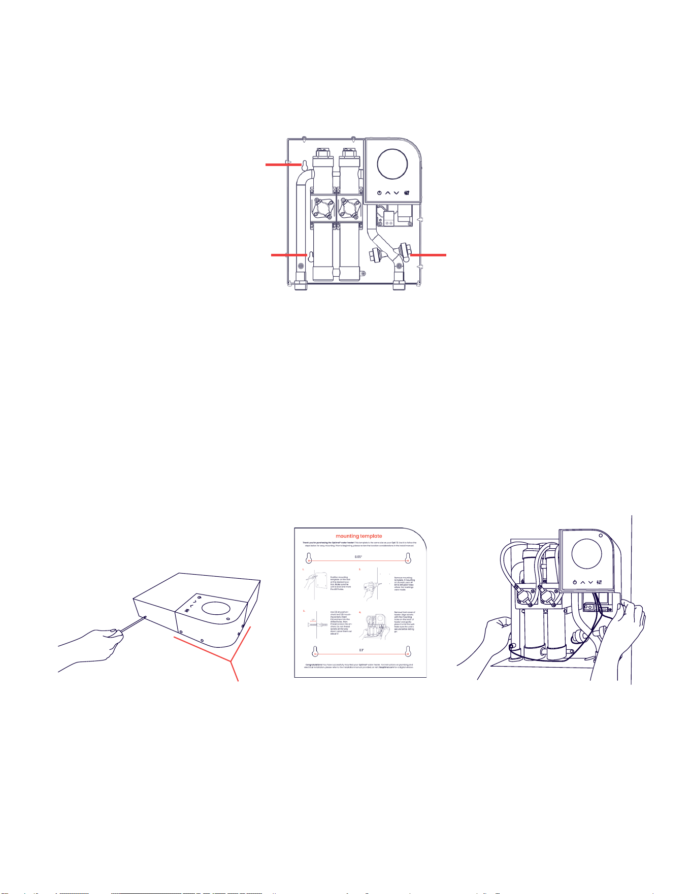
Please make sure the LED display is facing out and you are following all local building
codes.
Your product may require annual maintenance. Make sure to mount your product in an
area where you or your service technician can access it if necessary.
when you are ready to mount
mounting
hole
mounting
hole
mounting
hole
FRONT VIEW WITHOUT COVER
To mount your Optimal° water heater, remove the screws holding the front cover and
carefully follow the instructions on the mounting template included in the box with
your product.
Before installing your product, please review the following instructions carefully. We rec-
ommend that your Optimal° tankless water heater be installed by a licensed and qual-
ied professional in accordance with all applicable national, state, provincial, and local
plumbing codes.
do not
remove
Page 10
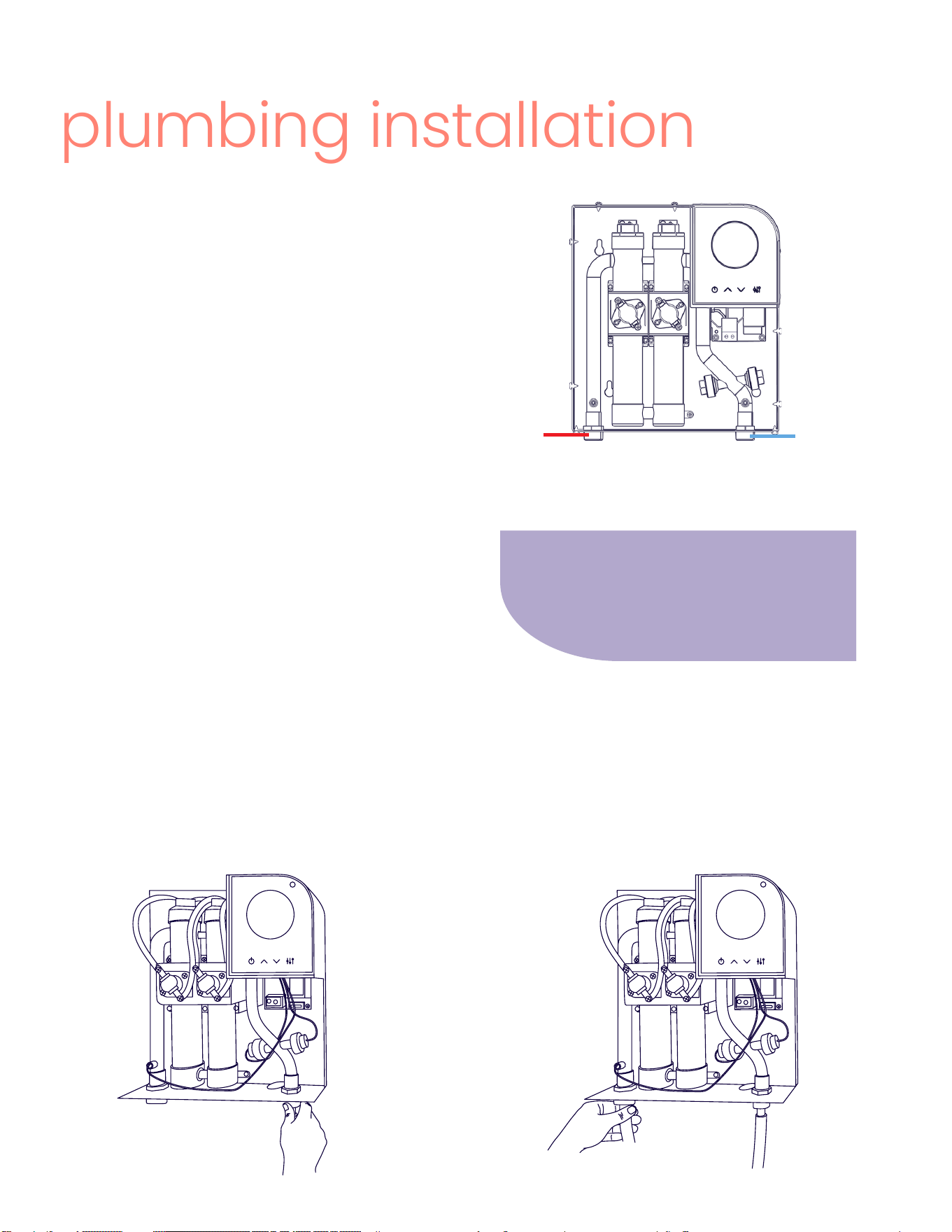
plumbing installation
It is recommended to have a manual
shut off valve installed within 5 ft of the
product’s inlet line for ease of mainte-
nance or service.
FRONT VIEW WITHOUT COVER
cold water
intlet
hot water
outlet
1. Connect the COLD WATER line to the
3/4” male connector on the COLD WATER
INLET. If needed, use plumber’s tape or
putty to prevent leaks.
2. Connect the HOT WATER line to the
3/4” male connector on the HOT WATER
OUTLET. If needed, use plumber’s tape or
putty to prevent leaks.
Before installing, conrm your hot water
line has been shut off. Copper or ap-
propriately rated exible braided hose
should attach directly to the inlet and
outlet connectors and run for at least
12” from the heater before adjoining to
other pipe material. All piping in the hot
water distribution line must be appro-
priately rated.
Your product is supplied with two 3/4”
NPT male connectors. If you are facing
the product, the cold water line is con-
nected to the bottom right side, and the
hot water line is connected to the bot-
tom left side.
If you are replacing an existing electric
tankless, you may have a 1/2 “ connec-
tion which will require an adapter or
converter to connect to 3/4”.
Page 11
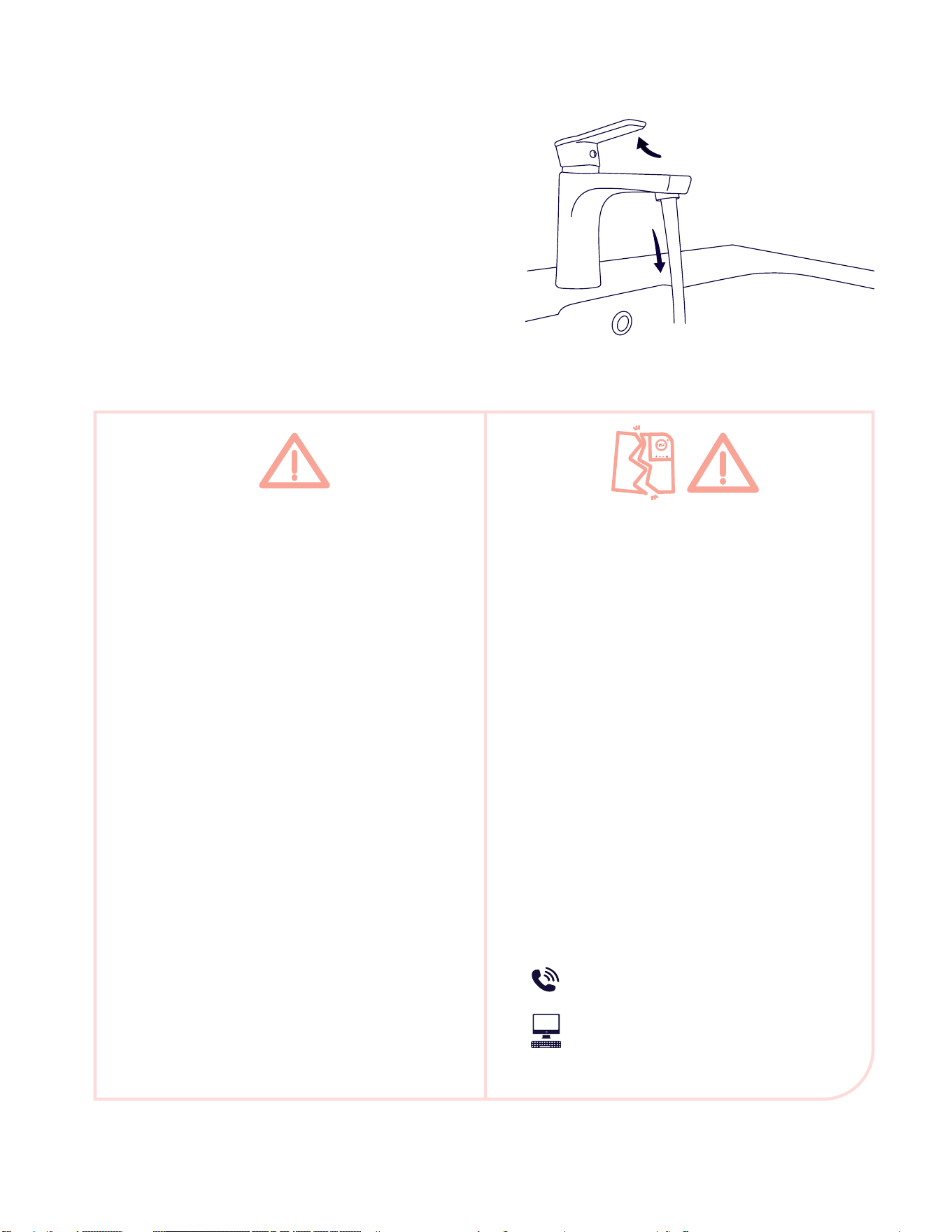
3. All air must be purged from the line
before starting the heater. After mak-
ing the plumbing connections, open
at least three hot water faucets and
allow them to run for at least three
minutes WITHOUT THE POWER ON.
4. While running the water to purge
the air, carefully inspect all connec-
tions, unions, and the pressure relief
valve (if installed) for leaks.
DAMAGE WARNING
Step 3 is mandatory. DO NOT SKIP!
Failure to follow can cause perma-
nent damage to the heating elements,
which is not covered by the warranty.
If any maintenance is performed on
the water heater or the home’s plumb-
ing system that may introduce air into
the plumbing pipes, YOU MUST turn the
power off to the water heater and purge
the air out of the lines before allowing
the product to power up.
If any leaks are detected in step 4, im-
mediately turn off water to the product
and contact Optimal° support.
SAFETY PRECAUTIONS - PLUMBING
• All plumbing work must comply with
national and applicable state and local
plumbing codes. A pressure-reducing
valve must be installed if the cold-water
supply pressure exceeds 150 psi. Make
certain that the cold-water supply line
has been ushed to remove any scale
and dirt.
• Do not solder any pipes connected to the
product. The heat may damage the ow
sensor. Doing so will void the warranty.
• UL Standard 499 does NOT require that
a pressure relief valve be used. However,
a T&P valve may be required to meet in-
stallation codes in your area. If one is re-
quired, install the pressure relief valve in
accordance with local codes and ensure
that it operates correctly, and that air is
purged from the valve prior to installing
the water heater.
386-OPTIMAL (386-678-4625)
itsoptimal.com
Page 12
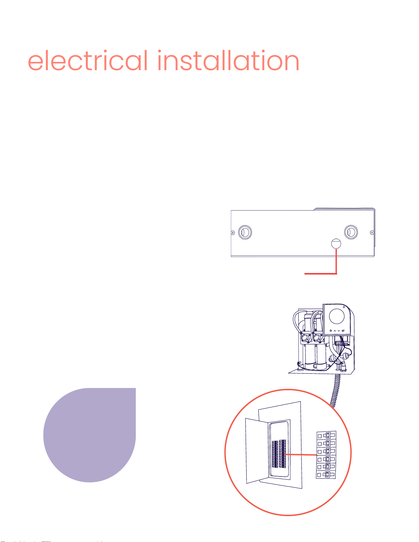
electrical installation
The Opti 27 requires three sets of 8 AWG wires (normally 1 red and 1 black for each set).
They connect to the three 40 amp double pole breakers in the electrical panel and run
to the terminal block on the power board. One ground wire (normally green) is included
in the each set. Using 8/2 Romex or its equivalent is recommended.
Please refer to the technical data table on Page 6 for electrical specications.
about the wiring
running the wire
The front cover of your Optimal° water
heater should already be removed from
mounting. If not, remove the front cover
as previously shown. There is a 1.25” pun-
chout hole with supplied Romex connec-
tor at the bottom of the product.
5. Pass the electrical wire coming from
the breakers through this punchout hole
and run it behind the copper exchanger
to meet the terminal block.
1.25” punchout with
Romex connector
Each circuit must
be connected to an
independent 40 amp
double pole breaker.
Ensure they do not
cross at the breaker.
40
amp
BOTTOM VIEW
40
amp
40
amp
40
amp
40
amp
40
amp
Page 13
SAFETY PRECAUTIONS - ELECTRICAL
DANGER – ELECTROCUTION: Before beginning any work on the electric installation, be sure
that the main breaker panel switches are "OFF" to avoid any danger of electric shock.
• All mounting and plumbing must be completed before proceeding with electrical
hook-up.
• Where required by local, state or national electrical codes the circuits should be
equipped with a "ground fault interrupter."
• The product must be properly grounded in accordance with state and local codes, or
in absence of such codes, in accordance with national electric code or the Canadian
electric code. Failure to electrically ground the product could result in serious personal
injury or death.
• All wiring (wire gauge) and circuit protection (breakers) must comply with the U.S. Na-
tional Electrical Code (NEC) in the USA, or the Canadian Electrical Code (CEC) in Can-
ada. Failure to do so could result in property damage and/or personal injury, and void
your warranty.
• Note: The Canadian Electrical Code generally requires that all supply wires and corre-
sponding circuit protection used for domestic hot water heating and hydronic heat-
ing applications be sized to a minimum of 125% of the maximum current rating of the
heater.
• Before installing this product, ensure that the home has sufcient electrical power
available to handle the maximum amperage load of the applicable model.
DAMAGE WARNING
All air must be purged from the line before starting the product. After making the plumbing
connections, open at least three hot water faucets and allow them to run for at least three
minutes WITHOUT THE POWER ON.
This step is mandatory. DO NOT SKIP! Failure to follow can cause permanent damage to
the heating elements, which is not covered by the warranty.
Page 14
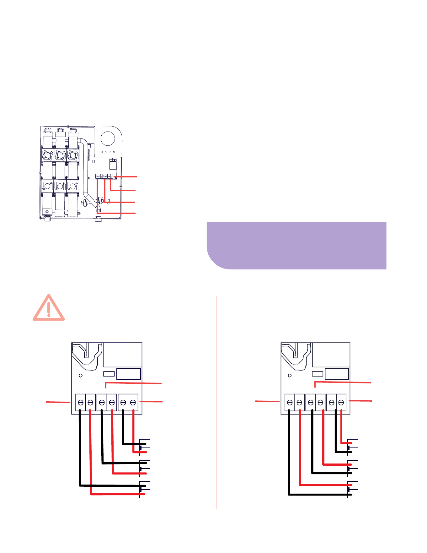
FRONT VIEW WITHOUT COVER
terminal blocks
6. Bring one of the three sets of 8 AWG
wires to the connectors on circuit 1 (C1
and C2) insert the leads, and secure them
by tightening the screws on the terminal
block using a athead screwdriver. Repeat
the same with the remaining sets of 8 AWG
wires for circuits 2 and 3. Do not cross the
wires at the breaker. See details below.
The terminal blocks (circuit 1, circuit 2, and circuit 3) are attached to the bottom of the
power board, just under the plastic control board housing. There are two wire connec-
tors (C1 and C2) at the bottom of each terminal block.
connecting the wire
breaker 1
breaker 2
c1 c1 c2 c2
DO NOT CROSS WIRES AT
THE BREAKER:
CORRECT:
circuit 1
circuit 2
circuit 3
breaker 3
circuit 1
circuit 2
c1 c2
circuit 3
c1 c1 c2 c2
c1 c2
circuit 1
circuit 2
circuit 3
breaker 1
breaker 2
breaker 3
Make sure the screw on the terminal
block is completely loosened to make
space to t the wire inside.

Page 15
7. Once the leads are
secured, tighten the
Romex connector at the
1.25” punchout on the
bottom of the unit. Make
sure to secure tightly
with enough slack so
the wire is not weighing
down the terminal block.
ground
C1
C2
All Optimal° water heaters are supplied with a grounding lug and screw.
8. To ground the unit, join the three(3) ground wires by twisting the ends together. Loos-
en the screw on the ground lug enough to wrap the ground wire around it. Then, tighten
the screw back down. If you are using a ring terminal on the ground wire, remove the
screw completely and reattach with the ring terminal secured to lug.
grounding the wire
FRONT VIEW WITHOUT COVER
ground
lug
Page 16
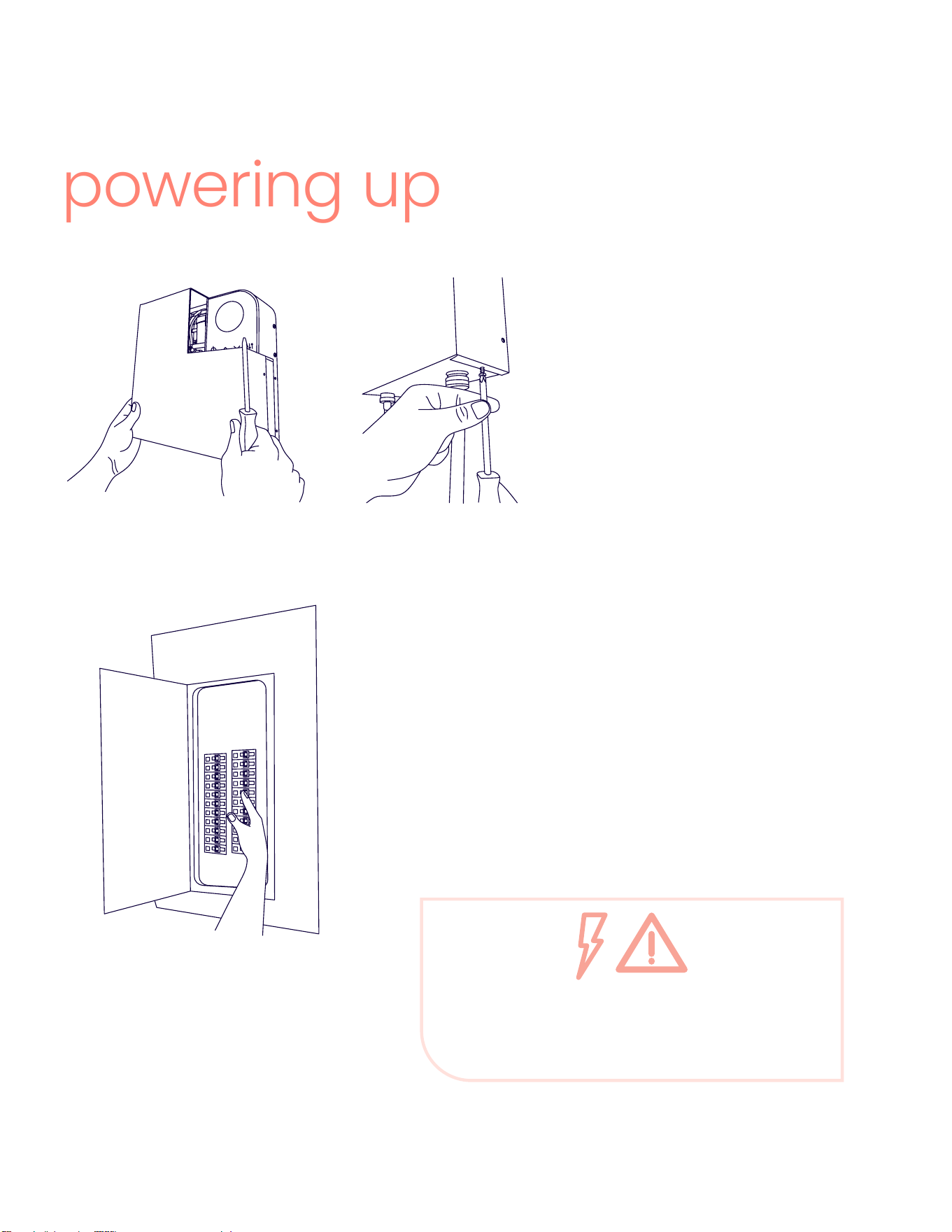
powering up
9. Once all wires have been
connected and air has been
ushed from the plumbing line,
secure the front cover back on
the product. And if you have not
done so already, close any run-
ning faucets.
10. Turn on the breakers.
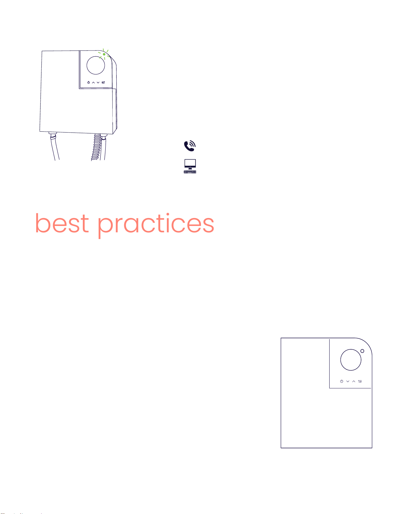
The power indicator on the top right of the
control panel will illuminate with various
colors when rst powered up and then hold a
steady green when it is ready to heat.
DANGER – ELECTROCUTION
At this point, the unit is live. DO NOT remove the
cover without again turning off the breaker.
Page 17
best practices
Welcome to on-demand heating! To fully enjoy the benets of endless hot water, it’s
helpful to understand your new capabilities.
Conventional tank water heaters are typically set between 120-140 degrees to prevent
bacterial growth. However, such temperatures can cause skin burns in just 30 seconds,
leading to the addition of cold water at the faucet.
The power indicator will turn white when hot
water is owing and the product is heating.
If the product is not powering on please con-
tact Optimal° support by giving us a call or
submitting a case form online.
386-OPTIMAL (386-678-4625)
itsoptimal.com
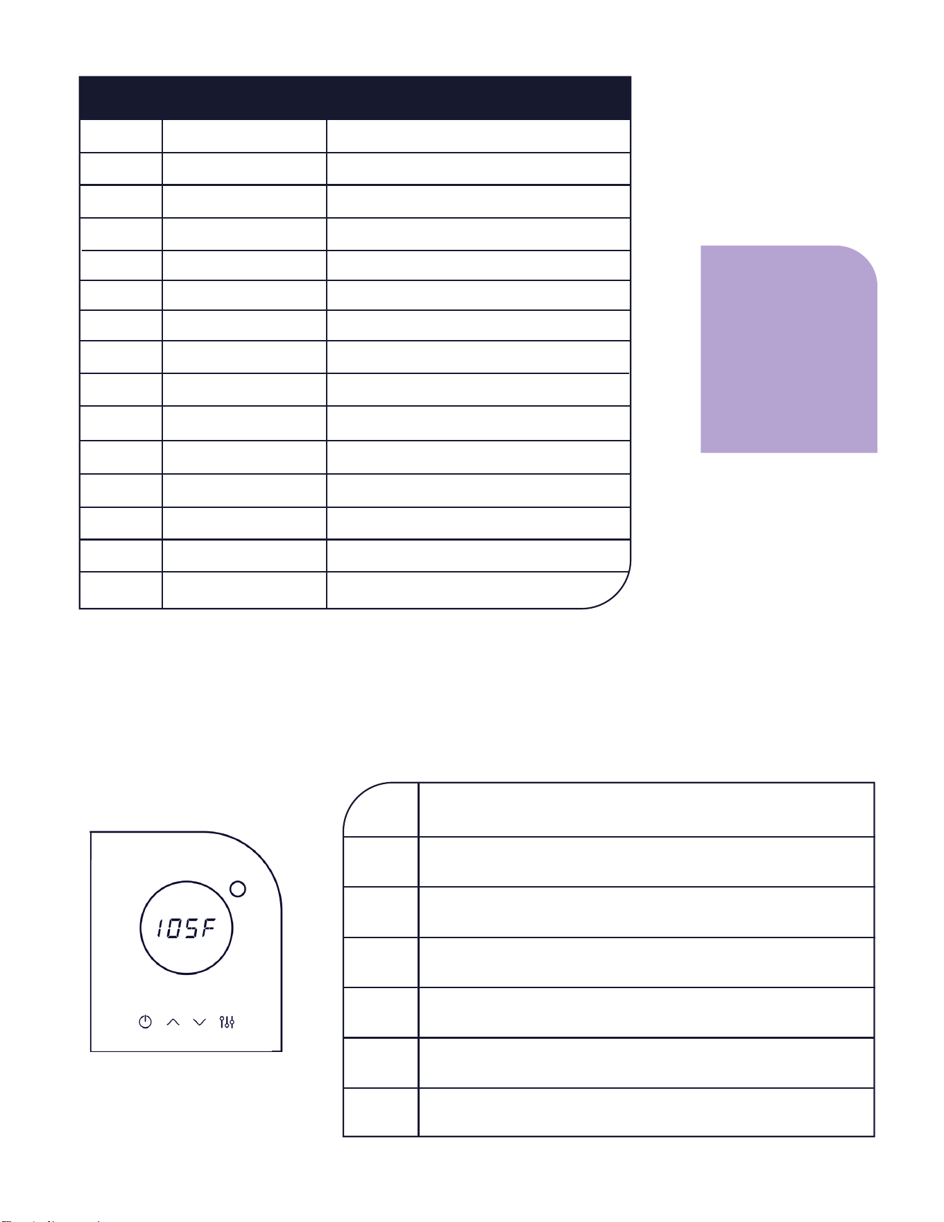
Now, you have the freedom to adjust the tempera-
ture precisely to your preference. While your Optimal°
heater comes set at 120 degrees, you might nd 105
degrees sufcient without mixing cold water.
Lowering the set temperature is a way to maximize
energy efciency while also increasing the ow rate
capacity that can be heated.
If you live in an area with a hard water supply contain-
ing a large amount of dissolved minerals, you may
want to consider a lter. Please visit itsoptimal.com for
more information on lter options.
105f
Page 18
Maintenance is essential for preventing damage due to calcication or electrolysis.
Flushing the heat exchanger with 1-2 gallons of white vinegar as necessary to remove
mineral build up will help extend the performance of the elements.
For more information, visit our website at itsoptimal.com and refer to the routine main-
tenance section.
routine maintenance
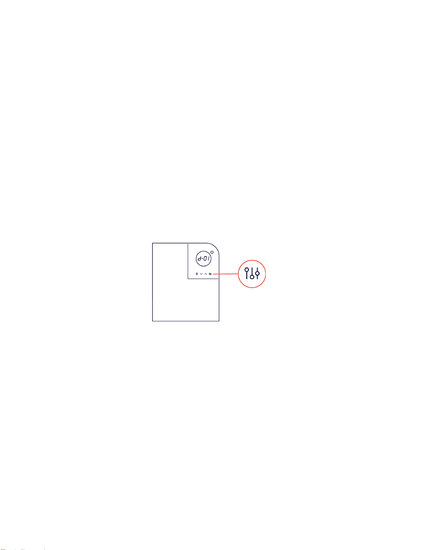
diagnostic mode
Optimal° water heaters are designed to inform. They can provide operational informa-
tion to the user, or helpful diagnostic tools for a support case if one is ever necessary.
To run diagnostics on your product locate the diagnostic button on the LED display and
press once.
The rst diagnostic, d-01 is your current ow rate. See the next page for a full list of
diagnostic and operational information. Use the up and down arrows to move up and
down the list.
To the see the detail, press the diagnostic button again when you have scrolled to the
item you want to see.
To exit diagnostic mode, press the power button once.
Page 19
# description
d-01
d-02
d-03
d-04
d-05
d-06
d-07
d-08
d-10
d-11
d-12
d-13
d-15
d-16
d-21
ow rate
voltage
input temperature
output temperature
heating power
heat capacity
ow capacity
heater calibration
ac cycles
model
build version word
number of circuits
freeze protect enable
vacation mode
temperature units
name
incoming gallons per minute (gpm)
input voltage (V)
input temperature
output temperature
actual heating power (W) ÷ 10
heat capacity (W) ÷ 10
available ow at set temp. (mgpm) ÷ 10
heater calib. (%)
input voltage cycle rate (Hz)
model, expressed in rated kW
software version/model
num. of circuits/elements
freeze protect enable
vacation mode
units: F or C
The diagnostic
numbers not listed
here are only for
Optimal° support.
Please do not ad-
just these without
contacting us.
The small circular light on the top right of the control panel is the power indicator. It will
light different colors based on its current mode.
understand power indicator colors
blue
green
white
red
teal
no light
purple
power is running to the heater, but it is in “off” mode. Water will
not heat. Push the power button to turn it on.
power is running, the heater is on and ready to heat when hot
water is running.
power is running and the elements are actively heating.
an error code has been detected. See next section for more
information on error codes.
the heater is in diagnostic mode.
the output temperature is not reaching the set temperature.
This means the ow rate is too high.
vacation mode
Page 20
The LED display on your Optimal° water heater is designed to notify of any issues that
may occur upon installation or during the product’s life.
If an error occurs, the LED display will read the letter “E” and a number, and the power
indicator light will show a solid red. For any error codes not listed here, please contact
Optimal° support.
error codes
error problem solution
E001
air in the line
1. Open at least three hot water faucets and let them run for two minutes or until the
error clears.
2. If the error persists, close the faucets and cycle power to the circuit breaker (turn
off for 10 seconds). Then turn the breaker back on, open one faucet, and check if the
error is cleared.
3. If E001 error returns, have the plumber/installer check for leaks.
E002
hot and cold
connections
crossed
1. Turn off breakers powering your heater.
2. Close heater water shutoff valve.
3. Open nearby hot water faucets slightly to release water and air until minimal dripping.
4. Swap and secure incoming/outgoing water lines.
5. Open water valve and ensure water ows through heater.
6. Flush air by running water through faucet for 2 minutes, then close.
7. Restore breaker power, open faucet, and check for issues.
heating
elements
E004
Contact customer support to order a new heating element. Visit itsoptimal.com/support
for replacement and maintenance instructions.
E008
thermostat
Contact our customer support team for assistance.
E016
voltage
1. Select the diagnostic button on the product display.
2. Scroll down to option two and select the diagnostic button again to check the supplied
voltage.
3. If the voltage is below 200v, contact your installer or electrician for further assistance.
E032
transducer
Contact our customer service team for troubleshooting.
E064
thermistor
1. Press the diagnostic button, scroll down to option 14, and press the diagnostic button
again.
2. Using the up and down arrows, set the LCD screen to display the number 0.
3. Press the diagnostic button to revert to the main menu, showing the E064 error code
again.
4. Turn on the hot water faucet and let it run for two minutes.
5. You should now receive hot water, but remember this is a temporary solution.
6. Contact our customer service team for further assistance.
Page 21
This Limited Lifetime Warranty is available to the original owner of the Opti electric tankless water heater (the
“Opti water heater") or, in connection with a transfer of real property containing an installed Opti water heater,
to the authorized transferee of such owner (collectively, the “end user”). It’s Optimal LLC (“Optimal°”) warrants the
Opti water heater, and its component parts, to be free from defects in materials and workmanship under normal
use and service for the Applicable Warranty Period (dened below).
If your Opti water heater fails in normal use and service during the Applicable Warranty Period, then, at its op-
tion, Optimal° will repair or replace the defective water heater, or defective component part(s), in accordance
with the terms of this Limited Lifetime Warranty. Any replacement or repaired product will be warranted only for
the unexpired portion of the original product’s Applicable Warranty Period.
Effective Date
The Effective Date of warranty coverage (or the beginning of the Applicable Warranty Period) is the original
invoice date of the Opti water heater. The original invoice date is the date Optimal° originally sold the Opti water
heater to an end user or resale partner
What does Limited Lifetime Warranty Mean? | Applicable Warranty Period
The term “Limited Lifetime Warranty” is intended to cover the useful life of the Warranted Parts in residential and
non-residential settings under normal use and service. Therefore, the Applicable Warranty Period depends on
whether the Opti water heater was purchased and installed in a private residence (a “Residence”) or purchased
and installed in a building that is not a private residence, including but not limited to, any commercial build-
ing, warehouse, ofce building, government building, school, or other building that is not intended for use as a
private residence (any of the foregoing, a “Non-Residential Building”). If the Opti water heater was installed in a
Residence, the Applicable Warranty Period is TWENTY-FIVE (25) years from the Effective Date. If the Opti water
heater was installed in a Non-Residential Building, the Applicable Warranty Period is FIVE (5) years from the Effec-
tive Date. The Limited Lifetime Warranty applies to the Heat Exchanger and all component parts (collectively, the
“Warranted Parts”) and applies solely to the replacement and/or repair of the Warranted Parts by Optimal° and
does not cover any labor or other costs of the end user associated with an installation, reinstallation, service, or
repair by end user of the Opti water heater.
IT’S OPTIMAL LLC
Manufacturer’s Limited Lifetime Warranty
For Opti Electric Tankless Water Heater Line
warranty
Exclusive Warranty – Limitations of Liability
ANY IMPLIED WARRANTIES, INCLUDING MERCHANTABILITY, OR FITNESS FOR
A PARTICULAR PURPOSE, SHALL NOT EXTEND BEYOND THE APPLICABLE
WARRANTY PERIODS SPECIFIED HEREIN EXCEPT WHERE EXPRESSLY RE-
QUIRED BY STATE LAW. OPTIMAL’S SOLE LIABILITY WITH RESPECT TO ANY
DEFECT SHALL BE AS SET FORTH IN THIS LIMITED LIFETIME WARRANTY, AND
ANY CLAIMS FOR INCIDENTAL OR CONSEQUENTIAL DAMAGES (INCLUDING
DAMAGE FROM WATER LEAKAGE) ARE EXPRESSLY EXCLUDED.

Page 22
Warranty Exclusions
This Limited Warranty will not cover:
a. Damages or failures resulting from failure to install the Opti water heater in accordance with applicable
building codes/ordinances or good plumbing and electrical trade practices.
b. Damages or failures resulting from improper installation or failure to operate and maintain the Opti water
heater in accordance with the manufacturer’s instructions provided.
c. Performance problems caused by improper sizing of the Opti water heater.
d. Damages or failures caused by abuse, accident, re, ood, freeze, lightning, acts of God, and the like.
e. Failures (leaks) caused by operating the Opti water heater in a corrosive or contaminated atmosphere.
f. Damages or failures caused by operating the Opti water heater with an empty, or partially empty, heat ex-
changer (also known as “dry ring”).
g. Failures caused by hard water supply such as calcication or electrolysis.
h. Damages or failures caused by subjecting the Opti water heater to pressures greater than those shown on
the rating label.
i. Damages or failures resulting from the use of any attachment or replacement part not authorized by Opti-
mal°.
j. Opti water heater purchased from a source other than from an authorized Optimal° resale partner.
k. Opti water heater where unauthorized part(s) were installed or made part of a product after purchase from
an authorized Optimal° resale partner.
l. Opti water heaters that have been removed from the original installation location.
m. Opti water heaters that have had their rating labels removed.
Labor, Shipping, And Processing Costs
This Limited Lifetime Warranty does not cover any labor expenses for service, repairs, reinstallation, permits, or re-
moval and disposal of the failed water heater, or defective component part(s). All such costs and expenses shall
be the end user’s responsibility.
Optimal° will pay for the cost of ground shipping within the continental US for the return of the failed water heat-
er, or defective component part(s), to a convenient shipping location (selected by Optimal°) for an “in-warranty”
replacement water heater, or “in-warranty” replacement component part(s). Optimal° will also pay for the cost of
ground shipping within the continental US of an Optimal° replacement or repaired Opti water heater or defective
component part(s) to the end user at a convenient delivery point (selected by Optimal°) near the place the origi-
nal water heater, or original component part(s), is located.
How To Obtain Warranty Claim Assistance
Any claim for warranty assistance must be timely made. If your Opti water heater has not been registered,
please begin by lling out the online warranty registration at itsoptimal.com to provide basic information about
your heater. This helps us process your claim more efciently. Once complete, you can submit a case form from
the Optimal° website or contact our customer support department at 386-OPTIMAL (386-678-4625).
Optimal° support technicians are available to address issues that may arise. This may include shipping a com-
ponent part(s), or sending a replacement unit with comparable operating features. Optimal° reserves the right
to inspect, or require the return of, the failed water heater or the defective component part(s). Each “in-warranty”
replaced Opti water heater must be made available to Optimal° (with the rating label and all the component
parts intact) in exchange for the replacement Opti water heater. Each defective “in-warranty” component part
to be replaced must be returned to Optimal° in exchange for the replacement component part. Customer credit
card information may be collected to secure the return of a replaced Opti water heater. If the replaced Opti water
heater is not shipped within thirty (30) days, the customer’s credit card may be charged the full MSRP of the Opti
water heater.
Warranty compensation is subject to validation of “in-warranty” coverage by Optimal° claims department per-
sonnel.
386-OPTIMAL (386-678-4625)
itsoptimal.com
Page 23
manual del propietario, guía de
instalación y soporte técnico
calentador de agua
electrico sin tanque
Page 24
tabla de contenidos
versión en inglés
precauciones de seguirdad
antes de instalar
montaje
instalación de plomería
instalación eléctrica
encendiendo
mejores prácticas
solución de problemas
garantía
2-22
25
26-27
27-28
29-30
31-34
35-36
36-37
37-39
40-41
Page 25
precauciones de seguridad
LEA TODAS LAS INSTRUCCIONES ANTES DE EMPEZAR
PELIGRO - Lesiones. Por favor lea y siga estas instrucciones. El incumplimiento de estas
instrucciones podría provocar lesiones graves o muerte.
DAÑO AL EQUIPO Y AL AMBIENTE. El equipo debe ser instalado por un electricista y
plomero autorizado. La instalación debe cumplir con todos los códigos de plomería y
electricidad nacionales, estatales y locales. El servicio del producto debe ser realizado
por técnicos de servicio calicados.
PELIGRO - Electrocución. Antes de realizar cualquier trabajo en este aparato,
asegúrese de apagar todos los interruptores eléctricos que lo alimentan. No retire la
cubierta sin desconectar la alimentación eléctrica, ya que esto podría causar lesiones
graves o mortales. Asegúrese de que el aparato esté adecuadamente conectado a
tierra para prevenir riesgos letales.
PELIGRO - Quemaduras. Las temperaturas del agua superiores a 125 °F (52 °C) pueden
causar quemaduras instantáneas graves o la muerte por escaldadura. Existe la posi-
bilidad de quemarse con agua caliente si el termostato del equipo está demasiado
alto. Los hogares con niños pequeños, discapacitados o personas mayores pueden
requerir que el termostato se ajuste a 113 °F (45 °C) o menos para evitar posibles le-
siones por agua caliente.
ADVERTENCIA - Lesiones. Si niños o personas con limitaciones físicas, sensoriales o
mentales usan este equipo, asegúrese de supervisarlos o darles instrucciones de se-
guridad. Los niños nunca deben jugar con el equipo y deben ser supervisados en todo
momento.
Conforms to UL STD. 499 & NSF/ANSI/CAN STD. 372 Certied to CSA STD. C22.2 NO. 64
Page 26
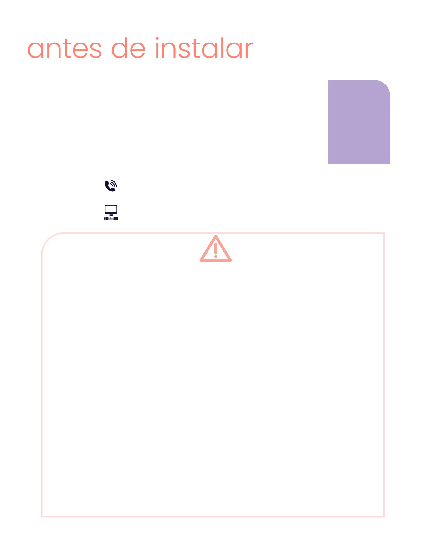
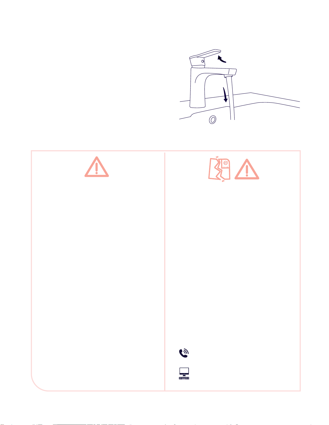
antes de instalar
Por favor, lea estas instrucciones antes de la instalación y el uso. No
seguir las instrucciones puede causar daños a la propiedad, lesiones
personales graves o la muerte. Al instalar este producto, usted acep-
ta los términos de la garantía del fabricante incluida en su producto.
Contáctenos si tiene alguna pregunta sobre la garantía o el produc-
to. Nuestro equipo de soporte está listo para ayudar. También puede
encontrar más información y enviar un formulario de consulta o case
form en nuestro sitio web.
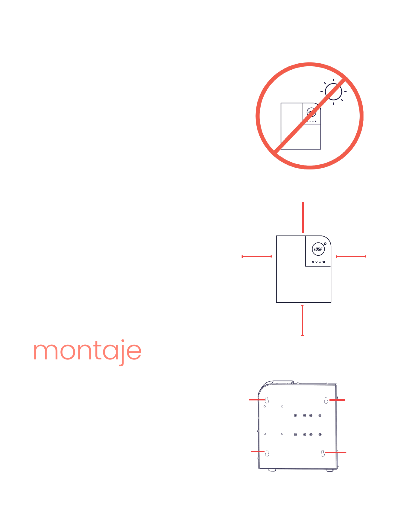
PRECAUCIONES DE SEGURIDAD-MONTAJE
NO instale este producto donde pueda estar sujeto a temperaturas bajo cero. Si el agua den-
tro del producto se congela puede causar daños irreparables no incluidos en la garantía.
NO instale el producto en un lugar con difícil acceso.
Instale el equipo fuera del alcance de los niños para que no puedan manipular los controles
de temperatura o lesionarse al tocar la línea de salida de agua caliente. La línea de agua de
salida puede alcanzar altas temperaturas.
Este producto NO requiere ventilación.
Evite instalar su calentador de agua sin tanque en áreas húmedas, polvorientas o expuestas a
salpicaduras de líquidos.
NO instale tuberías subacuáticas o líneas de aire acondicionado propensas a fugas o acumu-
lación de humedad, ya que podrían gotear sobre el calentador.
NO instale el producto encima de tomacorrientes o cajas eléctricas.
PRECAUCIÓN - MATERIALES COMBUSTIBLES: deben mantenerse a una distancia mínima de 24
pulgadas de su calentador de agua y de la línea de salida de agua caliente.
386-OPTIMAL (386-678-4625)
itsoptimal.com
Para obtener
una descrip-
ción general
de su Opti 27,
consulte la
información
en las páginas
4 a 6.
Page 27
dónde instalar
12,5”
6”
12,5”
6”
Acceso a un panel eléctrico
Acceso a una conexión de plomería
Supercie de montaje y espacio libre
Este producto está diseñado para instalarse
en interiores. Instalarlo en el exterior anulará la
garantía.
Tanto si usa el calentador para distribución en
toda la casa, como en un punto especíco de
uso, las tres principales consideraciones para la
ubicación son:
montaje
VISTA POSTERIOR
oricio de
montaje
oricio de
montaje
oricio de
montaje
oricio de
montaje
Su calentador de agua sin tanque
Optimal° tiene cuatro oricios de 1/2”
de montaje ubicados en la parte pos-
terior. Para facilitar la instalación y
el mantenimiento, recomendamos
que este producto se instale en una
posición vertical, con las conexiones
de entrada y salida de agua en la par-
te inferior del producto.
a.
b.
c.
1.
2.
3.
La supercie de montaje debe ser
segura y nivelada.
En el caso de montaje en paneles
de yeso, utilice anclajes.
Espacios libres recomendados:
• 12,5” arriba y abajo
• 6” a los lados
Page 28
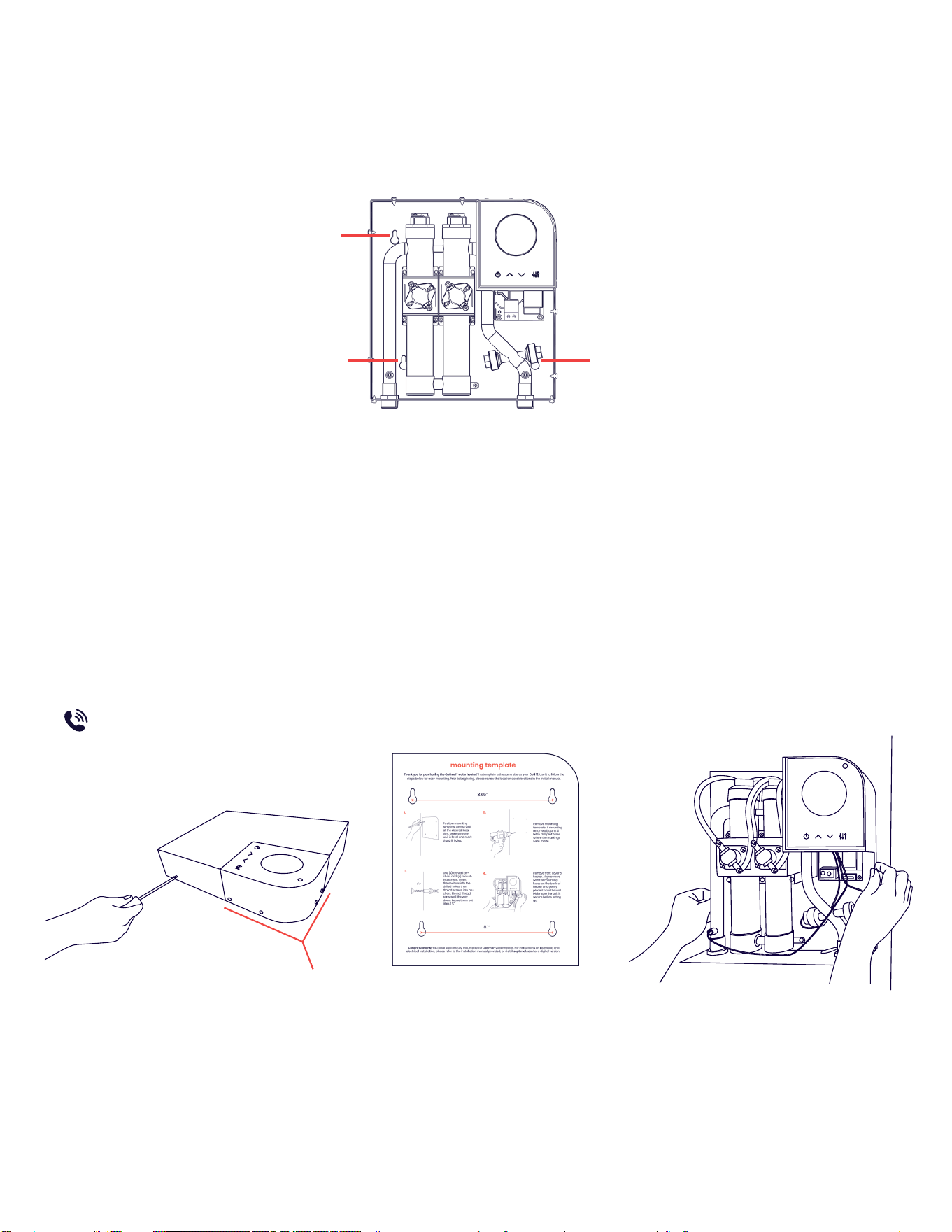
Listo para instalar?
oricio de
montaje
oricio de
montaje
oricio de
montaje
VISTA FRONTAL SIN CUBIERTA
Este producto puede ser instalado de forma lateral, sin perder sus características de
rendimiento. Asegúrese que la pantalla LED esté orientada hacia afuera y de seguir
todos los códigos de construcción locales.
Para montar su calentador de agua Optimal°, retire solo los tornillos de la cubierta
frontal de aluminio y siga cuidadosamente las instrucciones en la plantilla de montaje
incluida en la caja con su producto. Si tiene alguna pregunta no dude en llamarnos.
386-OPTIMAL (386-678-4625)
Su equipo puede requerir mantenimiento anual. Asegúrese de montar su calentador
en un área donde usted o su técnico de servicio puedan acceder si es necesario.
Antes de instalar su producto, por favor revise detenidamente las siguientes instruc-
ciones. Recomendamos que su calentador Optimal° sea instalado por un profesional
con licencia y calicado, de acuerdo con todos los códigos de plomería nacionales,
estatales, provinciales y locales aplicables.
no retire
Page 29
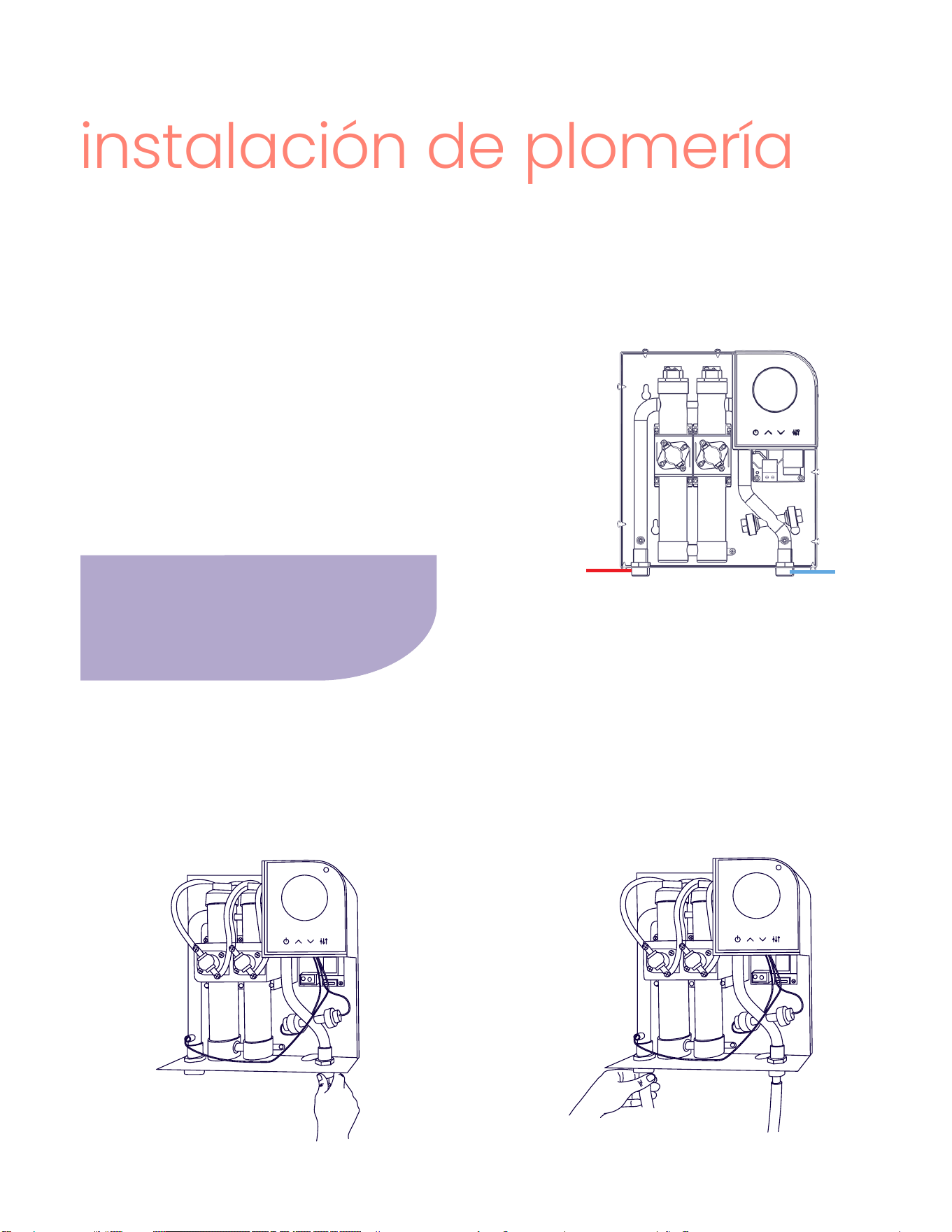
instalación de plomería
Recomendamos instalar una válvula de
cierre manual a menos de 5 pies de la
línea de entrada del equipo para facilitar
el mantenimiento de su producto.
línea de
agua fría
línea de
agua caliente
1. Conecte la línea de AGUA FRÍA al
conector macho de 3/4” en la entra-
da de agua fría (COLD WATER INLET).
Si es necesario, use cinta de teón o
masilla de plomero para evitar fugas.
2. Conecte la línea de AGUA CALIENTE al
conector macho de 3/4” en la entrada
de agua caliente (HOT WATER OUTLET).
Si es necesario, use cinta de teón o
masilla de plomero para evitar fugas.
Su producto incluye dos conectores macho de 3/4”
NPT. Si está frente al producto, la línea de agua fría
se conecta en la parte inferior derecha y la línea
de agua caliente se conecta en la izquierda. Si está
reemplazando un calentador eléctrico sin tanque
existente, es posible que tenga una conexión de 1/2“
que requerirá un adaptador para conectarla a 3/4”.
VISTA FRONTAL SIN CUBIERTA
Antes de instalar, conrme que su conexión de agua caliente esté cerrada. Conecte
mangueras de cobre o trenzadas exibles con la calicación adecuada a los conec-
tores de entrada y salida, asegurando que se extiendan al menos 12” desde el calenta-
dor antes de unirse a otra tubería. Todas las tuberías en la línea de distribución de
agua caliente deben tener la calicación adecuada.
Page 30
ADVERTENCIA DE DAÑOS
El paso 3 es obligatorio. ¡NO LO OMITA! El
incumplimiento puede causar daños per-
manentes a los elementos calefactores,
lo cual no está cubierto por la garantía.
Si se realiza algún mantenimiento en el
calentador de agua o en el sistema de
plomería de la casa que pueda introdu-
cir aire en las tuberías de plomería, DEBE
apagar el calentador de agua y purgar el
aire de las líneas antes de permitir que el
producto se encienda.
Si se detecta alguna fuga en el paso 4,
cierre inmediatamente el suministro de
agua al producto y comuníquese con el
soporte técnico de Optimal°.
PRECAUCIONES DE SEGURIDAD - PLOMERÍA
• Asegúrese de que toda la plomería cum-
pla con los códigos nacionales, estatales
y locales. Si la presión del suministro de
agua fría supera los 150 psi, instale una
válvula reductora de presión. No olvide
purgar la línea de suministro de agua fría
para eliminar incrustaciones y suciedad.
• Evite soldar tuberías conectadas al pro-
ducto, ya que el calor puede dañar el
sensor de ujo. Esto invalidará la garantía.
• Tenga presente que el estándar UL 499
NO requiere una válvula de alivio de
presión. Sin embargo, es posible que
deba instalar una válvula T&P para cum-
plir con los códigos de instalación en su
área. Si es necesario, instale la válvula de
alivio de presión conforme a las regula-
ciones locales, asegurándose de que fun-
cione correctamente y purgando el aire
antes de instalar el calentador de agua.
3. Antes de encender el calentador,
debe purgar completamente el aire
de la línea. Después de conectar la
plomería, abra al menos tres grifos
de agua caliente y déjelos correr
durante tres minutos SIN encender el
calentador.
4. Durante la purga de aire, revise
detenidamente todas las conexiones,
uniones y, si está instalada, la válvu-
la de alivio de presión en busca de
posibles fugas.
386-OPTIMAL (386-678-4625)
itsoptimal.com
Page 31
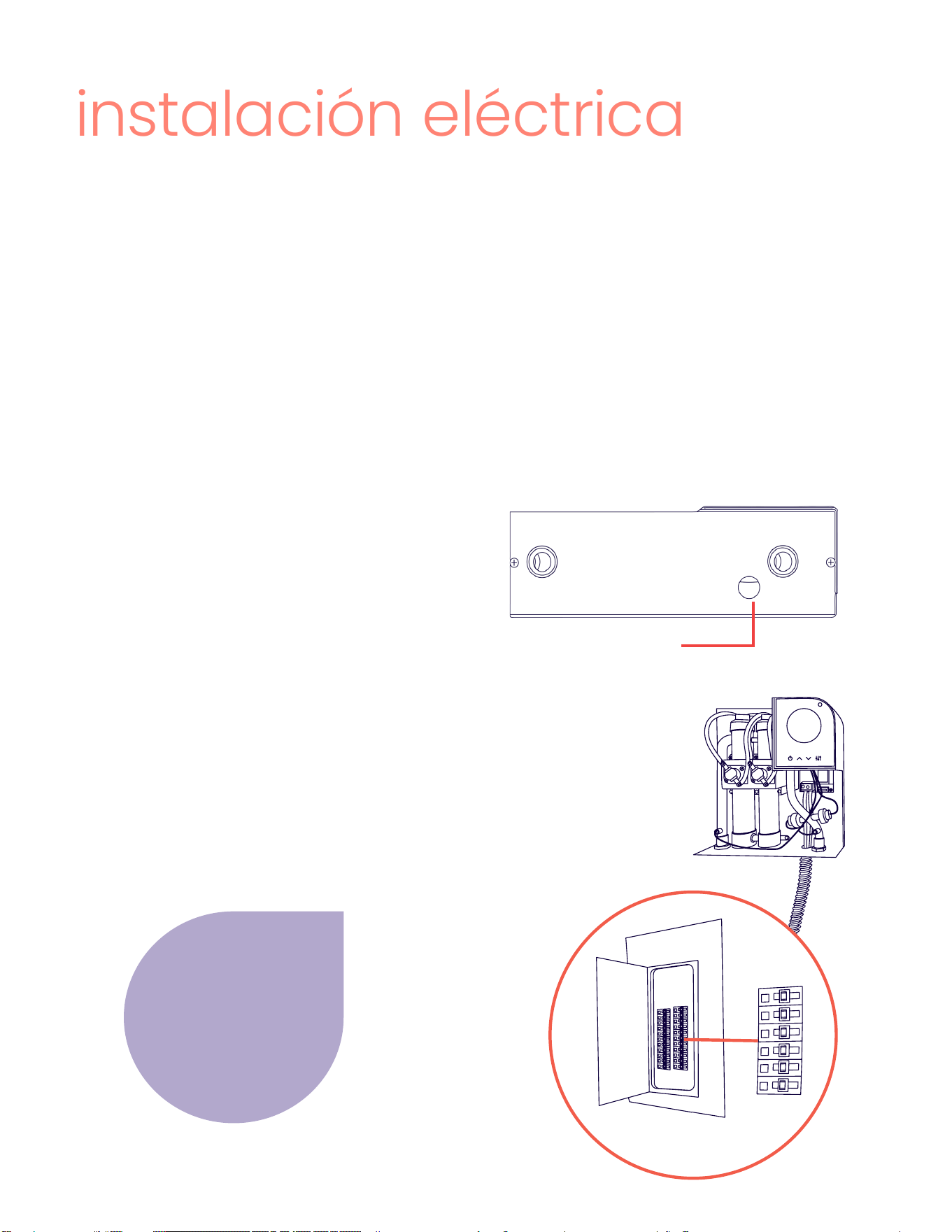
instalación eléctrica
El Opti 27 requiere tres sets de cables de 8 AWG (normalmente 1 rojo y 1 negro en cada
set) conectados desde dos interruptores dobles de 40 amp en el panel eléctrico has-
ta el bloque de terminales en la placa de alimentación, y 1 cable de tierra en cada set
(normalmente verde) que se conectan al terminal de tierra en el intercambiador de
calor. Se recomienda el uso de cable Romex 8/2 o su equivalente.
Para obtener información detallada sobre las especicaciones eléctricas, consulte la
tabla de datos técnicos en la página 6.
sobre el cableado
corriendo el cable
La cubierta frontal de su calentador
Optimal° debe haber sido retirada
en el montaje. Si no, siga las instruc-
ciones en la plantilla de montaje.
En la parte inferior del producto, verá
un oricio perforado de 1.25” con un
conector Romex.
5. Pase el cable eléctrico desde los
interruptores a través de este oricio
y córralo por detrás del intercam-
biador de cobre hacia el bloque de
terminales.
oricio perforado de 1.25”
con conector Romex
Cada circuito debe
estar conectado a un
interruptor doble de
40 amps. Asegúrese
de no cruzarlos en el
interruptor.
40
amp
40
amp
40
amp
40
amp
40
amp
40
amp
VISTA INFERIOR
Page 32
PRECAUCIONES DE SEGURIDAD-ELECTRICIDAD
PELIGRO DE ELECTROCUCIÓN: Antes de iniciar cualquier trabajo en la instalación eléctrica,
asegúrese de que los interruptores del panel principal estén APAGADOs para evitar riesgos
de descarga eléctrica.
• Asegúrese de completar todo el montaje y la plomería antes de proceder con la conex-
ión eléctrica.
• Cuando lo requieran los códigos eléctricos locales, estatales o nacionales, los circuitos
deben estar equipados con un “interruptor de falla a tierra”.
• El producto debe conectarse adecuadamente a tierra siguiendo los códigos estatales y
locales, o en ausencia de tales códigos, de acuerdo con el Código Eléctrico Nacional o
el Código Eléctrico Canadiense. La falta de conexión a tierra puede ocasionar lesiones
graves o incluso la muerte.
• Todo el cableado (calibre del cable) y la protección del circuito (interruptores) deben
cumplir con el Código Eléctrico Nacional (NEC) en EE. UU. o el Código Eléctrico Cana-
diense (CEC) en Canadá. No cumplir con estos requisitos podría resultar en daños a la
propiedad, lesiones personales y la invalidación de la garantía.
• Nota: El Código Eléctrico Canadiense suele exigir que todos los cables de suministro y
la protección del circuito correspondiente, utilizados en aplicaciones de calefacción de
agua caliente sanitaria y calefacción hidrónica, tengan un calibre mínimo del 125 % de
la corriente nominal máxima del calentador.
• Antes de instalar este producto, asegúrese de que su hogar cuente con la suciente ca-
pacidad eléctrica disponible para manejar la carga máxima de amperaje del modelo
correspondiente.
ADVERTENCIA DE DAÑOS
Es imprescindible purgar todo el aire de la línea antes de encender el calentador. Después de
realizar las conexiones de plomería, abra al menos tres grifos de agua caliente y permítalos
funcionar durante al menos tres minutos SIN ENERGÍA ELÉCTRICA.
Este paso es obligatorio. ¡NO LO OMITA! No seguirlo puede causar daños permanentes en los
elementos calefactores, los cuales no están cubiertos por la garantía.
Page 33
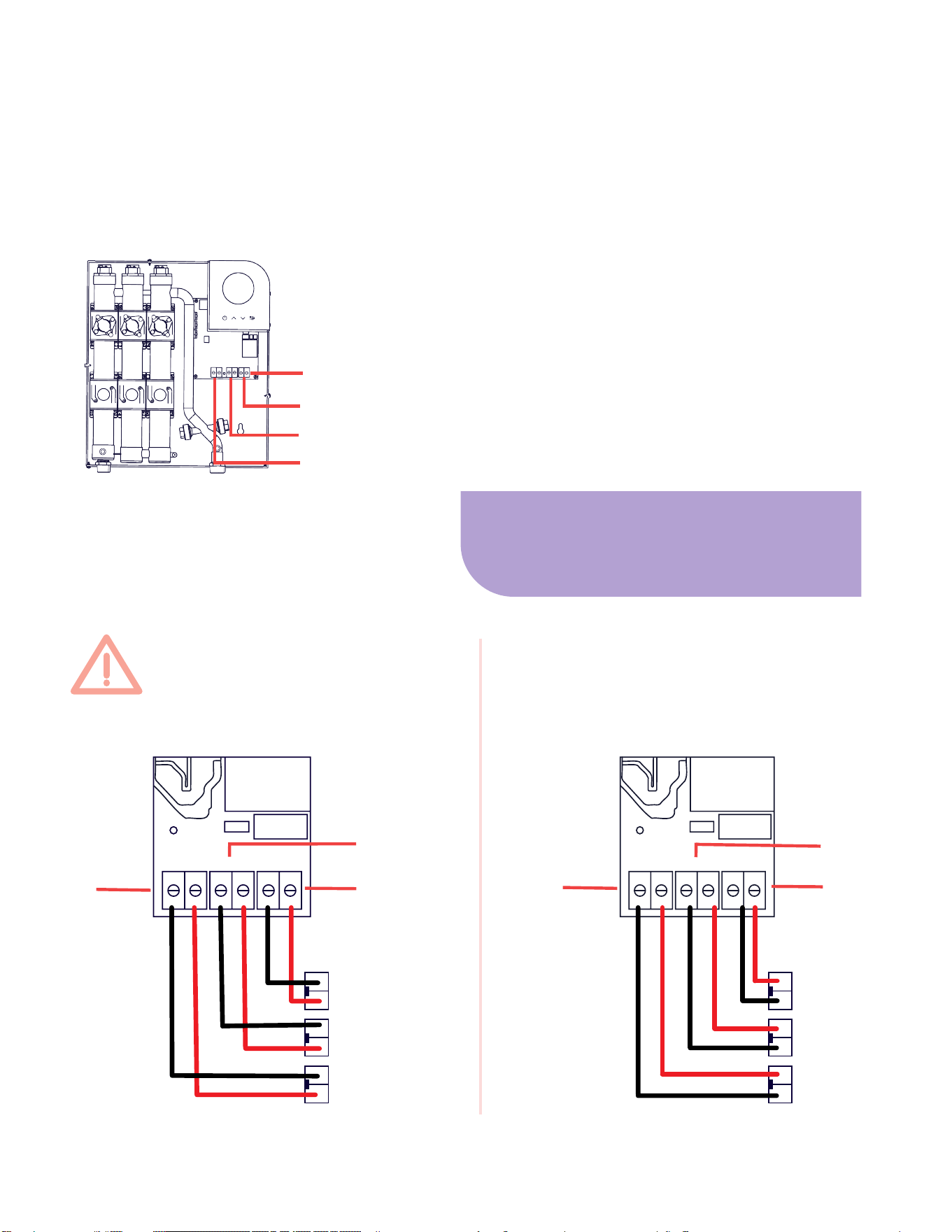
conectando el cable
Los bloques de terminales (circuito 1, circuito 2 y circuito 3) están sujetos en la parte
inferior de la placa de alimentación, justo debajo de la placa de control. Hay dos sets
deconectores de cables en la parte inferior de cada bloque de terminal (C1 y C2).
6. Lleve dos cables de calibre 8 AWG a los
conectores (C1 y C2), inserte los conduc-
tores y asegúrelos apretando los tornillos
en el bloque de terminales con un destor-
nillador de cabeza plana. Repita lo mismo
con los otros dos sets de cables de calibre
8 AWG para los circuitos 2 y 3. No cruce los
cables en el interruptor. Consulte los det-
alles a continuación.
NO CRUCE LOS CABLES
EN EL INTERRUPTOR:
CORRECTO:
VISTA FRONTAL SIN CUBIERTA
bloque de
terminales
circuito 1
circuito 2
circuito 3
interruptor 1
interruptor 2
c1 c1 c2 c2
interruptor 3
circuito 1
circuito 2
c1 c2
circuito 3
c1 c1 c2 c2
c1 c2
circuito 1
circuito 2
circuito 3
interruptor 1
interruptor 2
interruptor 3
Asegúrese que el tornillo en el bloque de
terminales esté completamente aojado
para crear espacio para que entre el cable.

Page 34
7. Una vez que los ex-
tremos estén asegura-
dos, ajuste el conector
Romex (1.25”) en la
parte inferior del pro-
ducto. Asegúrese de
dejar suciente holgura
para que el cable no
presione el bloque de
terminales.
Todos los calentadores de agua Optimal° están provistos de un terminal de puesta a
tierra y un tornillo.
8. Para conectar a tierra la unidad, una los (2) cables de tierra girando los extremos
juntos. Aoje el tornillo en la abrazadera de tierra lo suciente para envolver el cable
de tierra alrededor de él. Luego, vuelva a apretar el tornillo. Si está utilizando un termi-
nal anular en el cable de tierra, entonces retire completamente el tornillo y vuelva a
colocarlo con el terminal anular asegurado al terminal de la puesta a tierra.
cable a tierra
terminal de
puesta a
tierra
VISTA FRONTAL SIN CUBIERTA
ground
C1
C2
Page 35
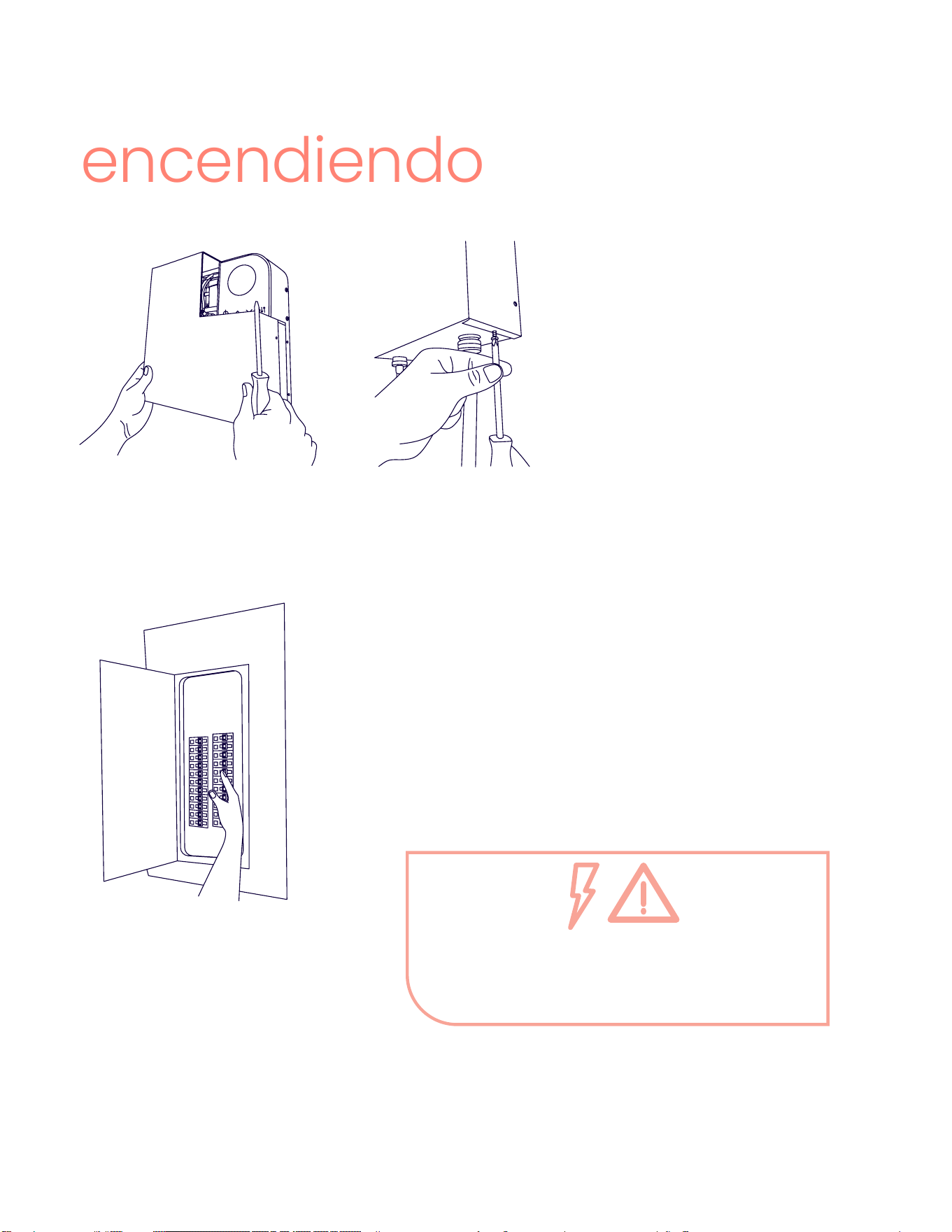
encendiendo
9. Una vez que todos los cables
estén conectados y se haya
purgado el aire de la línea de
plomería, cierre cualquier grifo
que esté abierto. Luego, ponga
y asegure la cubierta frontal
del producto.
10. Encienda los interruptores.
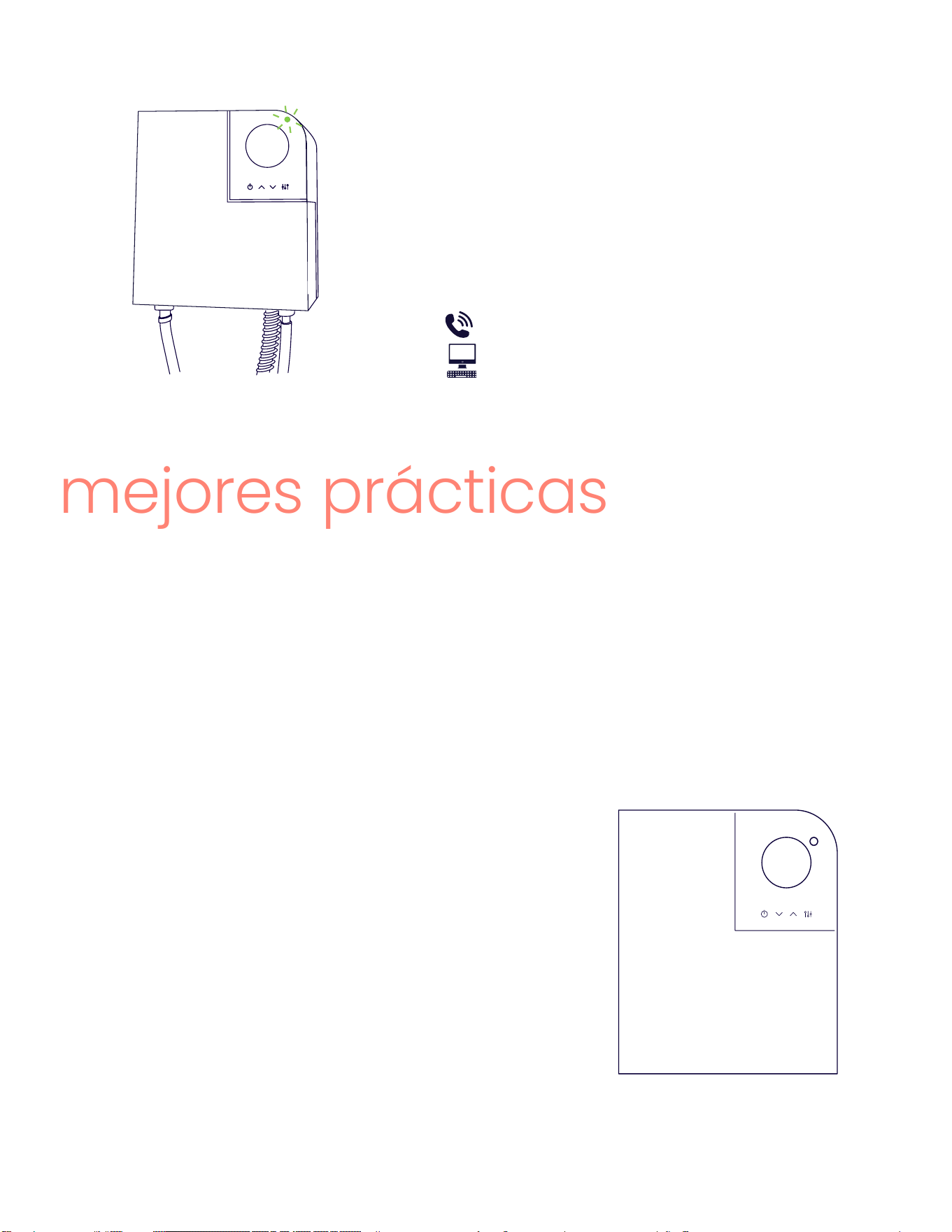
El indicador de energía en la parte superior derecha
del panel de control se iluminará con varios colores
cuando se encienda por primera vez. Luego per-
manecerá en verde constante cuando esté listo para
calentar.
PELIGRO – ELECTROCUCIÓN
En este punto, el producto está en funcionamiento.
NUNCA retire la cubierta sin apagar el interruptor.
Page 36
El indicador de energía se volverá blanco cuando
uya agua caliente y el producto esté calentando.
Si el producto no enciende, por favor contacte el
equipo de soporte de Optimal°.
mejores prácticas
¡Bienvenido al calentamiento de agua bajo demanda! Para disfrutar al máximo del
agua caliente ilimitada, es vital entender las capacidades de su producto.
Los calentadores de agua convencionales de tanque suelen ajustarse entre 120 y
140 grados para prevenir el crecimiento de bacterias. Sin embargo, tales temperatu-
ras pueden causar quemaduras en la piel en tan solo 30 segundos, lo que lleva a la
necesidad de agregar agua fría en el grifo.
386-OPTIMAL (386-678-4625)
itsoptimal.com
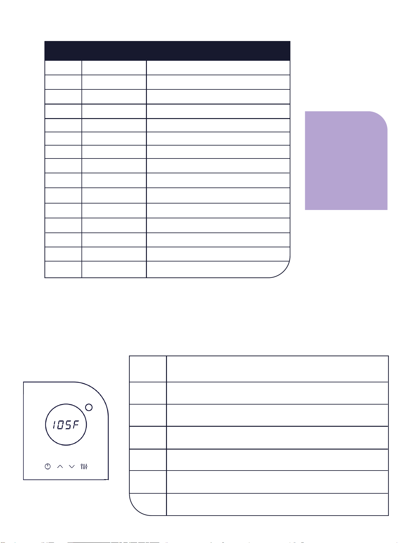
Ahora, tiene la libertad de ajustar la temperatura con
precisión según sus preferencias. Aunque tu calentador
Optimal° viene precongurado a 120 grados, es posible
que encuentres suciente una temperatura de 105 gra-
dos sin necesidad de mezclar agua fría.
Reducir la temperatura establecida es una forma de
maximizar la eciencia energética y, al mismo tiempo,
aumentar la capacidad de ujo que se puede calentar.
Si vive en una zona con un suministro de agua dura que
contiene una gran cantidad de minerales disueltos, es
posible que deba considerar un ltro. Por favor, visite
itsoptimal.com para obtener más información sobre
opciones de ltros.
105f
Page 37
mantenimiento regular
El mantenimiento es esencial para prevenir daños debidos a la calcicación o la elec-
trólisis. Enjuagar el intercambiador de calor con 1-2 galones de vinagre blanco según
sea necesario para eliminar la acumulación de minerales ayudara al rendimiento pro-
longado del calentador.
Para obtener más información, visita nuestro sitio web en itsoptimal.com y consulta la
sección de mantenimiento rutinario.
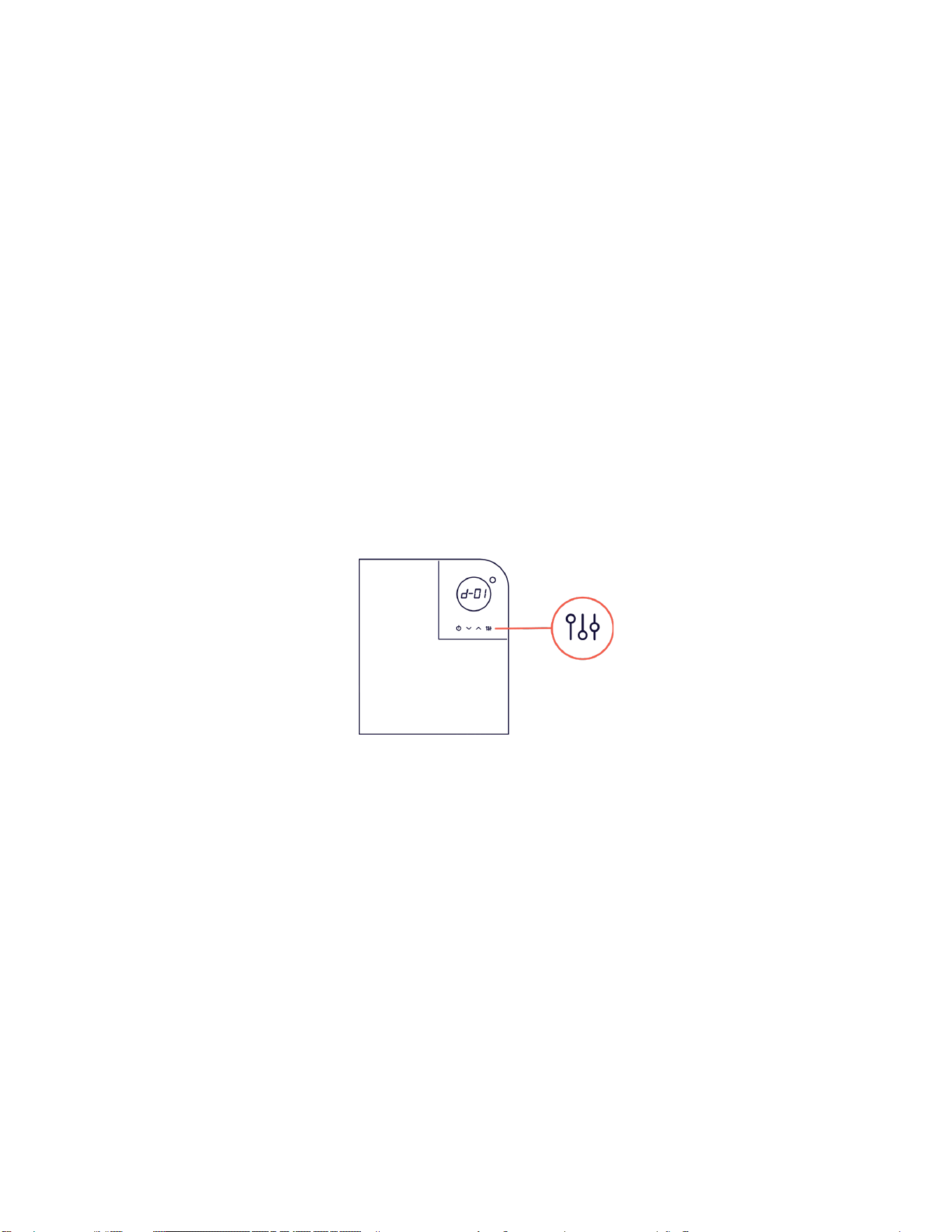
Los calentadores de agua Optimal° están diseñados para informar.
Para leer diagnósticos en su producto, localice el botón de diagnóstico en la pantalla
LED y presione una vez.
El primer diagnóstico, d-01, es su tasa de ujo actual. Consulte la siguiente página para
obtener una lista completa de información diagnóstica y operativa. Utilice las echas
hacia arriba y hacia abajo para moverse por la lista.
Para ver detalles, presione nuevamente el botón de diagnóstico cuando llegue al ele-
mento deseado.
Para salir del modo de diagnóstico, presione el botón de encendido.
modo diagnóstico
Page 38
mgpm entrante
voltaje de entrada (V)
temperatura de entrada
temperatura de salida
potencia de calentamiento real (W) ÷ 10
capacidad de calor (W) ÷ 10
ujo disponible a temp. establecida (mgpm) ÷ 10
calibración del calentador (%)
frecuencia de ciclo de voltaje de entrada (Hz)
modelo, expresado en kW nominal
versión/modelo de software
número de circuitos/elementos
activación de protección contra congelamiento
modo de vacaciones
unidades: °F o °C
El pequeño indicador luminoso circular en la parte superior derecha del panel de con-
trol es el indicador de energía. Emitirá diferentes colores según su modo actual.
indicador de energía
azul
verde
blanco
rojo
turquesa
no luz
morado
la energía está llegando al calentador, pero está en modo “apaga-
do”. El agua no se calentará. Presione el botón de encendido para
activarlo.
la energía está llegnado al calentador y está encendido y listo para
calentar cuando el agua caliente está en uso.
la energía está activa y los elementos están calentando activa-
mente.
se ha detectado un código de error. Consulte la siguiente sección
para obtener más información sobre los códigos de error.
el calentador está en modo de diagnóstico.
la temperatura de salida no está alcanzando la temperatura esta-
blecida. La velocidad de ujo es demasiado alta.
#
descripción
d-01
d-02
d-03
d-04
d-05
d-06
d-07
d-08
d-10
d-11
d-12
d-13
d-15
d-16
d-21
ujo
voltaje
temp. entrada
temp. salida
pot. calentamiento
cap. calor
capacidad de ujo
calib. calentador
ciclos de aire
modelo
versión
circ. num.
protección anti-hielo
modo vacaciones
unid. temp.
nombre
Los códigos no in-
cluidos en esta lista
son exclusivamente
para el equipo de
soporte de Optimal°.
Por favor, no los
ajuste sin contac-
tarnos.
modo de vacaciones
Page 39
La pantalla LED en su calentador de agua Optimal° está diseñada para noticar
cualquier problema que pueda ocurrir durante la instalación o la vida útil del producto.
Si hay un error, la pantalla LED mostrará la letra “E” seguida de un número, y la luz de
grados se iluminará en rojo sólido. Para cualquier código de error que no este en esta
lista, por favor contacte el soporte de Optimal°.
códigos de error
error
problema solución
E001
aire en la línea
1. Abra tres grifos de agua caliente durante dos minutos o hasta que de-
saparezca el error.
2. Si persiste, reinicie el interruptor del circuito (10 segundos apagado).
Luego encienda de nuevo, abra un grifo y verique.
3. Si el error E001 vuelve, llame al fontanero o instalador para revisar fu-
gas.
E002
conexiones
de agua fría
y caliente
cruzadas
1. Apague los interruptores que alimentan su calentador.
2. Cierre la válvula de cierre de agua del calentador.
3. Abra ligeramente las llaves de agua caliente cercanas para liberar
agua y aire hasta que goteen mínimamente.
4. Intercambie y asegure las líneas de agua de entrada/salida.
5. Abra la válvula de agua y asegúrese de que el agua uya a través del
calentador.
6. Enjuague el aire dejando correr agua a través del grifo durante 2 minu-
tos, luego ciérrelo.
7. Restaure la energía de los interruptores, abra el grifo y verique si hay
problemas.
elementos
calefactores.
E004
Comuníquese con nuestro servicio de atención al cliente para solicitar un
nuevo elemento calefactor. Visite itsoptimal.com/support para instruc-
ciones de reemplazo y mantenimiento.
E008
termostato
Comuníquese con nuestro equipo de soporte al cliente para obtener
ayuda.
E016
voltaje
1. Seleccione el botón de diagnóstico en la pantalla del equipo.
2. Desplácese hacia abajo hasta la opción dos y seleccione nuevamente el
botón de diagnóstico para vericar el voltaje suministrado.
3. Si el voltaje está por debajo de 200v, comuníquese con su instalador o
electricista para obtener más ayuda.
E032
transductor
Contacta nuestro servicio al cliente para ayuda.
E064
termistor
1. Encuentre la opción de diagnóstico en el producto.
2. Seleccione la opción de diagnóstico, desplácese hasta la opción 14 y
seleccione nuevamente el botón de diagnóstico.
3. Ajuste la pantalla LCD para mostrar el número 0.
4. Seleccione el botón de diagnóstico para volver al menú principal,
mostrando nuevamente el código de error E64.
5. Abra el grifo de agua caliente y deje que corra durante dos minutos.
6. Ahora debería recibir agua caliente, pero recuerde que esta es una solu-
ción temporal.
7. Si el problema persiste, comuníquese con nosotros.
Page 40
Esta Garantía Limitada de Por Vida está disponible para el propietario original del calentador de agua sin tanque
eléctrico Opti (el “calentador de agua Opti”) o, en relación con una transferencia de propiedad inmueble que
contenga un calentador de agua Opti instalado, para el cesionario autorizado de dicho propietario (en conjunto,
el “usuario nal”). It’s Optimal LLC (“Optimal°”) garantiza que el calentador de agua Opti y sus componentes están
libres de defectos en materiales y mano de obra bajo condiciones normales de uso y servicio durante el Período
de Garantía Aplicable (denido a continuación).
Si su calentador de agua Opti falla durante el uso y servicio normales durante el Período de Garantía Aplicable,
entonces, a su opción, Optimal° reparará o reemplazará el calentador de agua defectuoso o la(s) parte(s) de-
fectuosa(s), de acuerdo con los términos de esta Garantía Limitada de Por Vida. Cualquier unidad de reemplazo
o reparada estará garantizada solo por el período no vencido del Período de Garantía Aplicable de la unidad
original.
Fecha de Entrada en Vigor
La Fecha de Entrada en Vigor de la cobertura de garantía (o el inicio del Período de Garantía Aplicable) esla fecha
de factura original del calentador de agua Opti. La fecha de la factura original es la fecha en la que Optimal°
vendió originalmente el calentador de agua Opti a un usuario nal o socio de reventa.
¿Qué signica “Garantía Limitada de Por Vida” | Período de Garantía Aplicable
El término “Garantía Limitada de Por Vida” está destinado a cubrir la vida útil de las Piezas Garantizadas en
entornos residenciales y no residenciales bajo condiciones normales de uso y servicio. Por lo tanto, el Período
de Garantía Aplicable depende de si el calentador de agua Opti fue comprado e instalado en una residencia
privada (una “Residencia”) o fue comprado e instalado en un edicio que no es una residencia privada, incluyen-
do, entre otros, cualquier edicio comercial, almacén, edicio de ocinas, edicio gubernamental, escuela u otro
edicio que no esté destinado para su uso como residencia privada (cualquiera de los anteriores, un “Edicio No
Residencial”). Si el calentador de agua Opti fue instalado en una Residencia, el Período de Garantía Aplicable es
de VEINTICINCO (25) años a partir de la Fecha de Entrada en Vigor. Si el calentador de agua Opti fue instalado en
un Edicio No Residencial, el Período de Garantía Aplicable es de CINCO (5) años a partir de la Fecha de Entrada
en Vigor. La Garantía Limitada de Por Vida se aplica al Intercambiador de Calor y todas las piezas componentes
(en conjunto, las “Piezas Garantizadas”) y se aplica únicamente al reemplazo y/o reparación de las Piezas Garan-
tizadas por parte de Optimal°, sin cubrir ningún costo de mano de obra u otros costos del usuario nal asociados
con la instalación, reinstalación, servicio o reparación del calentador de agua Opti por parte del usuario nal.
IT’S OPTIMAL LLC
Garantia Limitada de Por Vida del Fabricante
Para la Linea de Calentadores de Agua sin Tanque Opti
garantía
Garantía Exclusiva - Limitaciones de Responsabilidad
CUALQUIER GARANTÍA IMPLÍCITA, INCLUYENDO LA COMERCIABILIDAD O APTITUD
PARA UN PROPÓSITO PARTICULAR, NO SE EXTENDERÁ MÁS ALLÁ DE LOS PERÍODOS
DE GARANTÍA APLICABLES ESPECIFICADOS AQUÍ, EXCEPTO DONDE SEA EXPRESA-
MENTE REQUERIDO POR LA LEGISLACIÓN ESTATAL.
LA ÚNICA RESPONSABILIDAD DE OPTIMAL CON RESPECTO A CUALQUIER DEFEC-
TO SERÁ COMO SE ESTABLECE EN ESTA GARANTÍA LIMITADA DE POR VIDA, Y SE
EXCLUYEN EXPRESAMENTE CUALQUIER RECLAMACIÓN POR DAÑOS INCIDENTALES
O CONSECUENTES (INCLUYENDO DAÑOS POR FUGA DE AGUA).

Page 41
IT’S OPTIMAL LLC
Garantia Limitada de Por Vida del Fabricante
Para la Linea de Calentadores de Agua sin Tanque Opti
Exclusiones de la Garantía
Esta Garantía Limitada no cubrirá:
a. Daños o fallas resultantes de la falta de instalación del calentador de agua Opti de acuerdo con los códigos/or-
denanzas de construcción aplicables o las buenas prácticas de plomería y electricidad.
b. Daños o fallas resultantes de una instalación incorrecta o de no operar y mantener el calentador de agua Opti
de acuerdo con las instrucciones del fabricante.
c. Problemas de rendimiento causados por un dimensionamiento incorrecto del calentador de agua Opti.
d. Daños o fallas causados por abuso, accidente, incendio, inundación, congelación, rayos, actos de Dios y similares.
e. Fallas (ltraciones) causadas por el funcionamiento del calentador de agua Opti en una atmósfera corrosiva o
contaminada.
f. Daños o fallas causados por el funcionamiento del calentador de agua Opti con un intercambiador de calor
vacío o parcialmente vacío (también conocido como “disparo en seco”).
g. Fallas causadas por el suministro de agua dura, como la calcicación o la electrólisis.
h. Daños o fallas causados por someter el calentador de agua Opti a presiones mayores que las indicadas en la
etiqueta de calicación.
i. Daños o fallas resultantes del uso de cualquier accesorio o pieza de repuesto no autorizada por Optimal°.
j. Calentador de agua Opti comprado en una fuente que no sea un revendedor autorizado de Optimal°.
k. Calentador de agua Opti en el que se instalaron o se incorporaron piezas no autorizadas después de la compra
a un revendedor autorizado de Optimal°.
l. Calentadores de agua Opti que han sido retirados de la ubicación de instalación original.
m. Calentadores de agua Opti que hayan tenido sus etiquetas de calicación retiradas.
COSTOS DE MANO DE OBRA, ENVÍO Y PROCESAMIENTO
Esta Garantía Limitada de Por Vida no cubre ningún gasto de mano de obra para servicio, reparaciones, reinsta-
lación, permisos o retirada y disposición del calentador de agua defectuoso o las piezas componentes defectuosas.
Todos estos costos y gastos serán responsabilidad del usuario nal.
Optimal° pagará el costo del envío terrestre dentro de los Estados Unidos continentales para la devolución del
calentador de agua defectuoso o las piezas componentes defectuosas a una ubicación de envío conveniente
(seleccionada por Optimal°) para un calentador de agua de reemplazo “bajo garantía” o piezas componentes de
reemplazo “bajo garantía”. Optimal° también pagará el costo del envío terrestre dentro de los Estados Unidos conti-
nentales para enviar un calentador de agua Opti de reemplazo o piezas componentes reparadas o defectuosas al
usuario nal en un punto de entrega conveniente (seleccionado por Optimal°) cerca del lugar donde se encuentra el
calentador de agua original o las piezas componentes originales.
Cómo Obtener Asistencia para Reclamos de Garantía
Cualquier reclamo de asistencia de garantía debe hacerse de manera oportuna. Si su calentador de agua Opti no
ha sido registrado, comience por completar el registro de garantía en itsoptimal.com para brindar información bási-
ca sobre su calentador. Esto nos ayuda a procesar su reclamo de manera más eciente. Una vez completado, puede
enviar un formulario de caso desde el sitio web de Optimal° o ponerse en contacto con nuestro departamento de
atención al cliente al 386-OPTIMAL (386-678-4625).
Los técnicos de soporte de Optimal° están disponibles para resolver problemas que puedan surgir. Esto puede incluir
el envío de una pieza o piezas de repuesto, o el envío de una unidad de reemplazo con características operativas
comparables. Optimal° se reserva el derecho de inspeccionar o exigir la devolución del calentador de agua defec-
tuoso o de la pieza o piezas defectuosas. Cada calentador de agua Opti reemplazado “bajo garantía” debe estar
disponible para Optimal° (con la etiqueta de calicación y todas las piezas intactas) a cambio del calentador de
agua Opti de reemplazo. Cada pieza defectuosa “bajo garantía” que deba ser reemplazada debe ser devuelta a
Optimal° a cambio de la pieza de repuesto. La información de la tarjeta de crédito del cliente puede ser recopilada
para asegurar la devolución del calentador de agua Opti reemplazado. Si el calentador de agua Opti reemplazado
no se envía dentro de treinta (30) días, la tarjeta de crédito del cliente podría ser cargada con el precio de venta al
público sugerido del calentador de agua Opti.
La compensación de garantía está sujeta a la validación de la cobertura “bajo garantía” por parte del personal del
departamento de reclamaciones de Optimal°.
386-OPTIMAL (386-678-4625)
itsoptimal.com