Residential Electronic Thermostat
Electric Water Heater
Installa on Instruc ons and
Use & Care Guide
Keep this manual in the pocket on heater for future reference whenever maintenance, adjustment or service is required.
Retain your original receipt as proof of purchase.
Table of Contents ................................... Page
Important Safety Informa on ............................................... 3
Ge ng Started ....................................................................... 6
Installa on .............................................................................. 7
Opera on ............................................................................. 16
Troubleshoo ng ................................................................... 20
Maintenance ........................................................................ 25
Diagrams............................................................................... 32
Repair Parts .......................................................................... 33
LOW LEAD
C
O
NTENT
100376565_2000804829_REV. A
January 2024
DO NOT RETURN THIS UNIT TO THE STORE
Read this manual and the labels on the water heater before you install,
operate, or service it. If you have diffi culty following the direc ons, or
aren’t sure you can safely and properly do any of this work yourself:
• Call your Local plumbing supplies store to have this water heater installed. Profes-
sional Installa on is available for this product and the work is guaranteed.
• Schedule an appointment with a qualifi ed person to install your water heater.
• Call our Technical Assistance Hotline at 1-800-527-1953 . We can help you with in-
stalla on, opera ons, troubleshoo ng, or maintenance. Before you call, write down
the model and serial number from the water heater’s data plate.
Incorrect installa on, opera on, or service can damage the water heater, your house
and other property, and present risks including fi re, scalding, electric shock, and
explosion, causing serious injury or death.
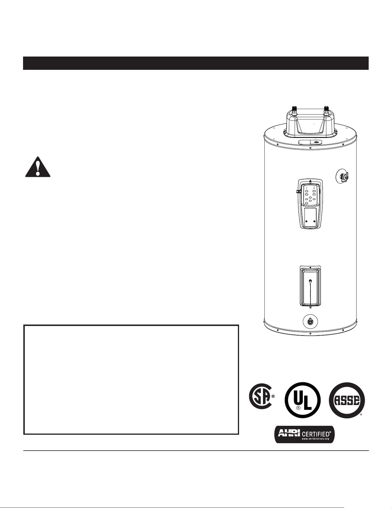
AHRI Cer fi ca on® applies to residen al electric water heaters with rated capaci es
of 20 to 120 gallon and input ra ngs of 12 kw or less.
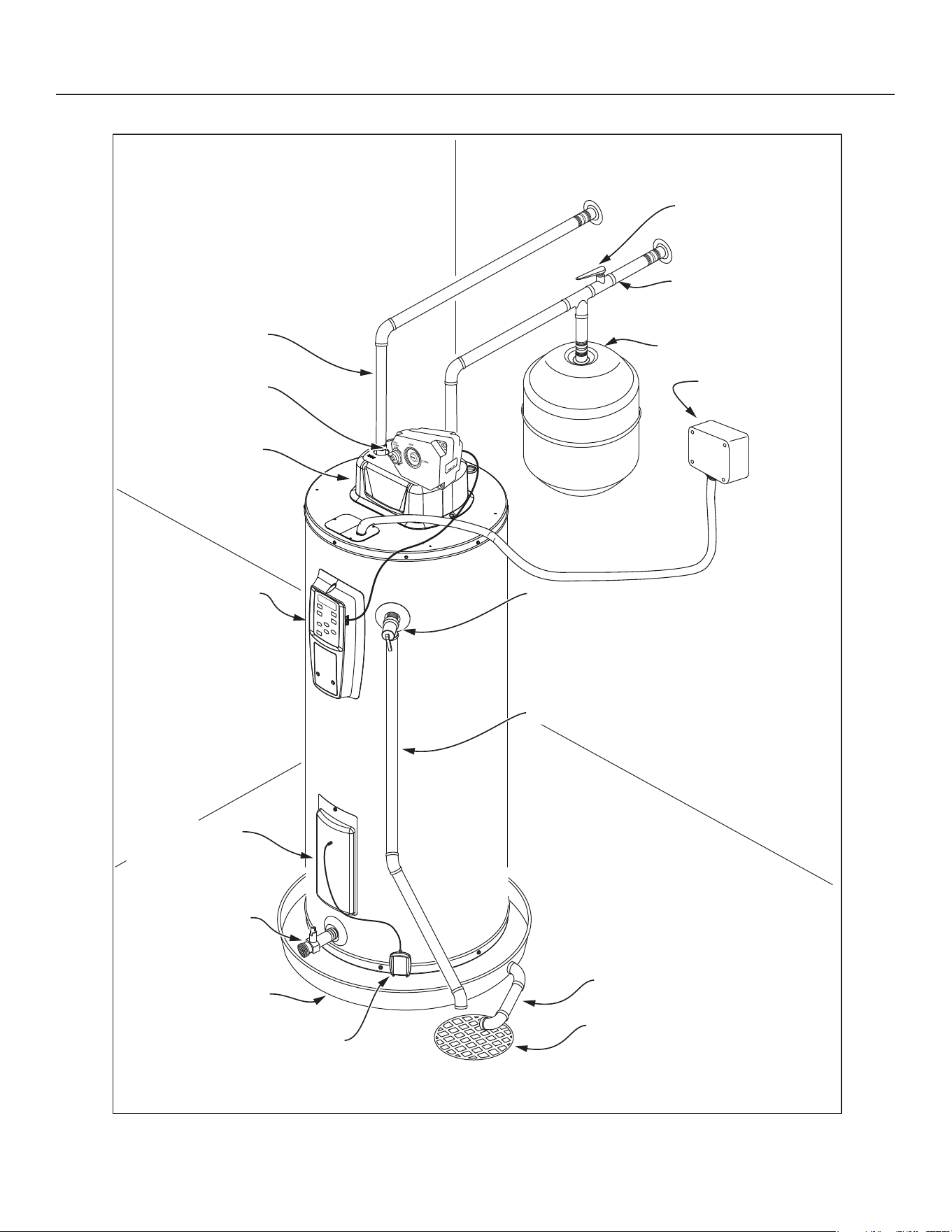
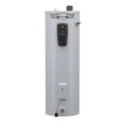
COMPLETED INSTALLATION TYPICAL
Quick Release
to remove valve body
Hot water line
Water shut
o valve
Cold water line
Expansion tank
Electrical junction
box
T&P relief valve
T&P discharge pipe
Drain pan discharge pipe
Drain
Automatic cold
water cut-o valve
(Optional)
Control pannel
Lower element &
lower relay access
Drain valve
Drain pan
Leak detection sensor
Smart Valve
w/Shroud
SAFETY
Residen al Electronic Thermostat Electric Water Heater Use and Care Guide • 3
IMPORTANT SAFETY INFORMATION
Important informa on to keep
Fill out this sec on and keep this
manual in the pocket of the water
heater for reference.
Date Purchased:
Model number:
Serial number:
Maintenance performed:* Date:
*Drain and flush tank, and remove and inspect anode rod after first six months of operation and at least annually thereafter.
Operate the Temperature and Pressure Relief Valve (T&P) annually and inspect T&P valve every 2-4 years (see the label on the
T&P valve for maintenance schedule). If no label is attached to the T&P Relief Valve, follow the instructions in the T&P Relief Valve
Maintenance section of this manual. See the Maintenance section for more information about maintaining this water heater.
This product is cer fi ed to comply with a maximum weighted average of
0.25% lead content as required in some areas.
This is the safety alert symbol. It is used to alert you to
poten al physical injury hazards. Obey all safety messages
that follow this symbol to avoid possible property damage,
serious injury or death. Do not remove any permanent
instruc ons, labels, or the data plate from either the outside
of the water heater or on the inside of the access panels. Keep this manual
near the water heater.
DANGER
DANGER indicates hazardous
situa on that, if not avoided, will
result in death or serious injury.
WARNING
WARNING indicates a hazardous
situa on that, if not avoided, could
result in death or serious injury.
CAUTION
CAUTION indicates a hazardous
situa on that, if not avoided, could
result in minor or moderate injury.
NOTICE
NOTICE indicates prac ces not
related to physical injury.
Read and follow all safety messages and instruc ons in this
manual.
ASSE 1082 Test Condi ons
40 Gallon
Model
50 Gallon
Model
55 Gallon
Model
Water Heater Connec on Size 3/4" NPT
Maximum Se ng 150°F (66°C)
Maximum Working Pressure 150 PSI (1034 kPa)
Maximum Flow Rate at Minimum
Temperature Rise
2 GPM
(7.5 L/min)
2.5 GPM
(9.5 L/min)
2.75 GPM
(10.5 L/min)
Minimum Flow Rate at Maximum
Temperature Rise
.5 GPM
(1.9 L/min)
.6 GPM
(2.3 L/min)
.7 GPM
(2.6/min)
Maximum Flow Rate at +70°F (+39°C)
Temperature Rise
2 GPM
(7.5 L/min)
2.5 GPM
(9.5 L/min)
2.75 GPM
(10.5 L/min)
Pressure Drop at Maximum Flow Rate
1.75 PSI
(12 kPa)
2.25 PSI
(15.5 kPa)
2.5 PSI
(17.2 kPa)
4 • Residen al Electronic Thermostat Electric Water Heater Use and Care Guide
IMPORTANT SAFETY INFORMATION
T
o reduce the risk of property
damage, serious injury or death,
read and follow the precau ons below,
all labels on the water heater, and
the safety messages and instruc ons
throughout this manual.
RISKS DURING INSTALLATION
AND MAINTENANCE
Electric Shock Risk
Contact with the electrical
parts in the junction box and
behind the access doors can
result in severe injury or death from
electrical shock:
Disconnect power by open-
ing the circuit breaker or
removing the fuses before
installing or servicing.
Use a non-contact circuit
tester to confirm that power
is off before working on or
near any electrical parts.
Replace the junction box
cover and access doors after
servicing.
Li ing Risk
WARNING! The
water heater is heavy.
Follow these precau-
ons to reduce the risk of property
damage, injuries from li ing or impact
injuries from dropping the water
heater.
Use at least two people to li the
water heater.
Be sure you both have a good grip
before li ing.
U se an appliance dolly or hand
truck to move the water heater.
Scalding Risk
This water heater can
make water hot
enough to cause
severe burns instantly, resulting in
severe injury or death.
• Feel water before bathing or
s howering
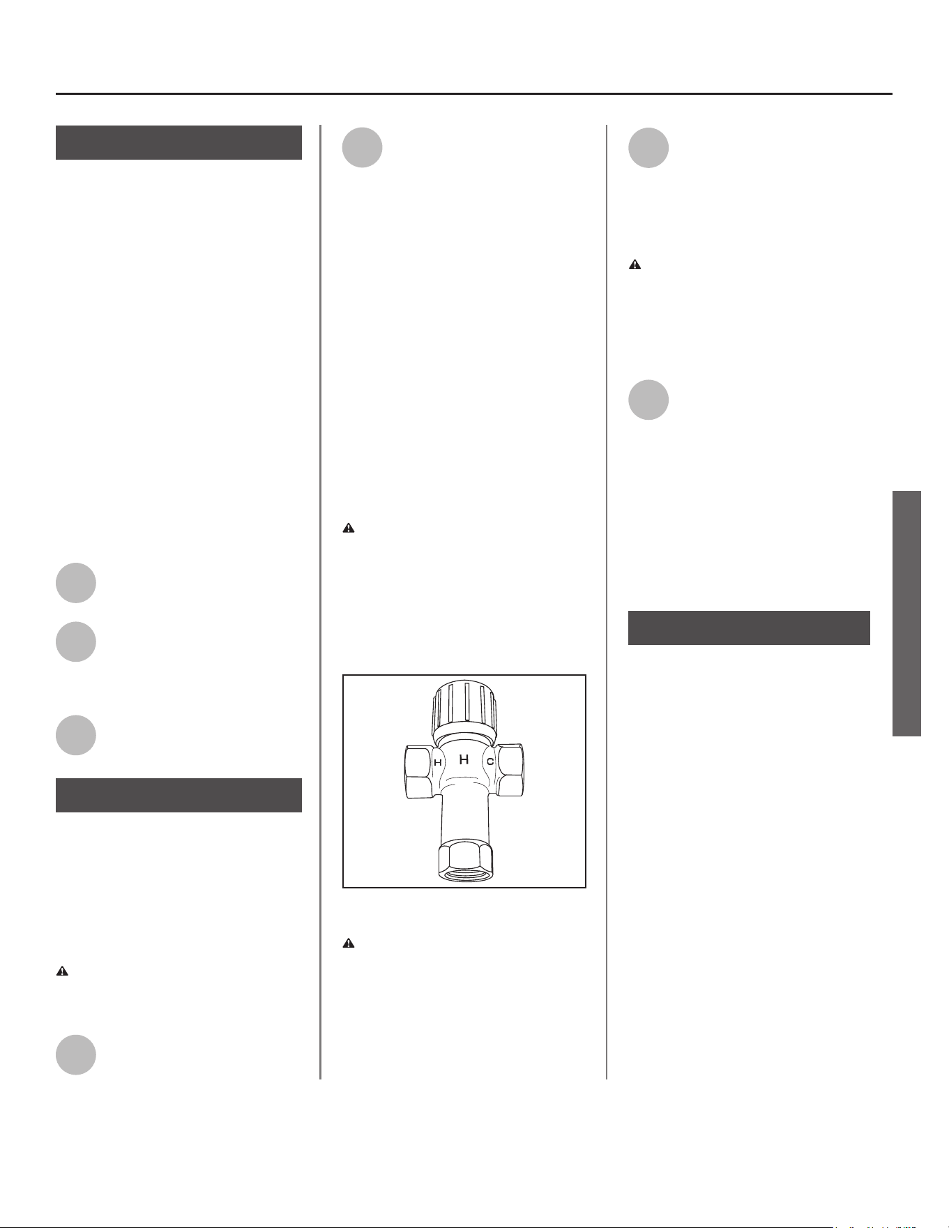
• To reduce the risk of scalding, install
Thermostatic Mixing Valves (tempera-
ture limiting valves) at each point-
of-use. These valves automatically
mix hot and cold water to limit the
temperature at the tap. Mixing valves
are available from your local plumb-
ing supplier. Follow manufacturer’s
instructions for installation and adjust-
ment of the valves.
• The thermostat(s) on this water
heater have been factory set to
approximately 120°F to reduce the
risk of scalding. Higher tempera-
tures increase the risk of scalding,
but even at 120°F, hot water can
scald. If you choose a higher tem-
perature, Thermostatic Mixing
Valves located at each point-of-use
are particularly important to help
avoid scalding.
Temperature Time to Produce
a Serious Burn
120°F (49°C) More than 5 minutes
125°F (52°C) 1½ to 2 minutes
130°F (54°C) About 30 seconds
135°F (57°C) About 10 seconds
140°F (60°C) Less than 5 seconds
145°F (63°C) Less than 3 seconds
150°F (66°C) About 1½ seconds
155°F (68°C) About 1 second
For informa on about changing the
factory thermostat se ng(s), refer to
the “Adjus ng Temperature” sec on in
this manual (“Step 11” on page 15).
Even if you set the water heater
thermostat(s) to a low se ng, higher
temperatures may occur in certain
circumstances:
In some cases, repeated small draws of
water can cause the hot and cold water
in the tank to “stack” in layers. If this
happens, the water can be as much as
thirty degrees ho er than the thermo-
stat se ng. This temperature varia on
is the result of your usage pa ern and
is not a malfunc on.
Water temperature will be ho er if
someone adjusted the thermostat(s) to
a higher se ng.
Problems with the thermostat(s),
or other malfunc ons may result in
higher than expected water tempera-
tures.
If the water heater is in a hot envi-
ronment, the water in the tank can
become as hot as the surrounding air,
regardless of the thermostat se ng.
If the water supplied to the water
heater is pre-heated (for example, by
fa solar system) the temperature in
the tank may be higher than the water
heater’s thermostat se ng.
To reduce the risk of unusually hot wa-
ter reaching the fi xtures in the house,
install Thermosta c Mixing Valves at
each point-of-use.
If anyone in your home is at par cular
risk of scalding (for example, the el-
derly, children, or people with disabili-
es) or if there is a local code or state
law requiring a certain water tempera-
ture at the hot water tap, then these
precau ons are par cularly important.
According to a na onal standard Ameri-
can Society of Sanitary Engineering
(ASSE 1070) and most local plumbing
codes, the water heater’s thermostat
should not be used as the sole means to
regulate water temperature and avoid
scalds.
SAFETY
Residen al Electronic Thermostat Electric Water Heater Use and Care Guide • 5
Properly adjusted Thermosta c Mixing
Valves installed at each point-of-use al-
low you to set the tank temperature to
a higher se ng without increasing risk
of scalds. A higher temperature se ng
allows the tank to provide much more
hot water and can help provide proper
water temperatures for appliances such
as dishwashers and washing machines.
Higher tank temperatures (140°F)
also kill bacteria that cause a condi-
on known as “smelly water” and can
reduce the levels of bacteria that cause
water-borne diseases.
Water Contamina on Risk
Do not use chemicals that could con-
taminate the potable water supply. Do
not use piping that has been treated
with chromates, boiler seal, or other
chemicals.
Fire Risk
To reduce the risk of a
fire that could destroy
your home and serious-
ly injure or kill people:
• D o not store things that can burn
easily such as paper or clothes next
to the water heater.
• Be sure the junction box cover and
the access door covers are in place.
These covers keep debris from enter-
ing and potentially being ignited,
and help keep any internal fires from
spreading.
• Keep the water heater from becom-
ing wet. Immediately shut the water
heater off and have it inspected by a
qualified person if you find that the
wiring, thermostat(s) or surround-
ing insulation have been exposed to
water in any way (e.g., leaks from
plumbing, leaks from the water heat-
er itself can damage property and
could cause a fire risk). If the water
heater is subjected to flood condi-
tions or the thermostat(s) have been
submerged in water, the entire water
heater must be replaced.
• Make electrical connections properly,
according to the instructions on page
14. Use 10 gauge solid copper wire.
Use a UL listed or CSA approved
strain relief. Connect ground wire to
green ground screw.
Explosion Risk
High temperatures and
pressures in the water
heater tank can cause an
explosion resul ng in property
damage, serious injury or death. A
new Temperature and Pressure (T&P)
Relief Valve is included with your water
heater to reduce risk of explosion by
discharging hot water. Addi onal
temperature and pressure protec ve
equipment may be required by local
codes.
A na onally recognized tes ng labora-
tory maintains periodic inspec on of
the valve produc on process and cer -
fi es that it meets the requirements
for Relief Valves for Hot Water Supply
Systems, ANSI Z21.22. The T&P Relief
Valve’s relief pressure must not exceed
the working pressure ra ng of the wa-
ter heater as stated on the ra ng plate.
Maintain the T&P Relief Valve properly.
Follow the maintenance instructions
provided by the manufacturer of the
T&P Relief Valve (label attached to T&P
Relief Valve). If no label is attached
to the T&P Relief Valve, follow the
instructions in the T&P Relief Valve
Maintenance section of this manual.
An explosion could occur if the T&P
Relief Valve or discharge pipe is
blocked. Do not cap or plug the T&P
Relief Valve or discharge pipe.
Fire and Explosion Risk if Hot Water is
Not Used for Two Weeks or More
C AUTION! Hydrogen gas builds up in
a hot water system when it is not used
for a long period (two weeks or more).
Hydrogen gas is extremely fl ammable.
If the hot water system has not been
used for two weeks or more, open a
hot water faucet for several minutes at
the kitchen sink before using any elec-
trical appliances connected to the hot
water system. Do not smoke or have
an open fl ame or other igni on source
near the faucet while it is open.
SAFETY
IMPORTANT SAFETY INFORMATION
6 • Residen al Electronic Thermostat Electric Water Heater Use and Care Guide
GETTING STARTED
GETTING STARTED
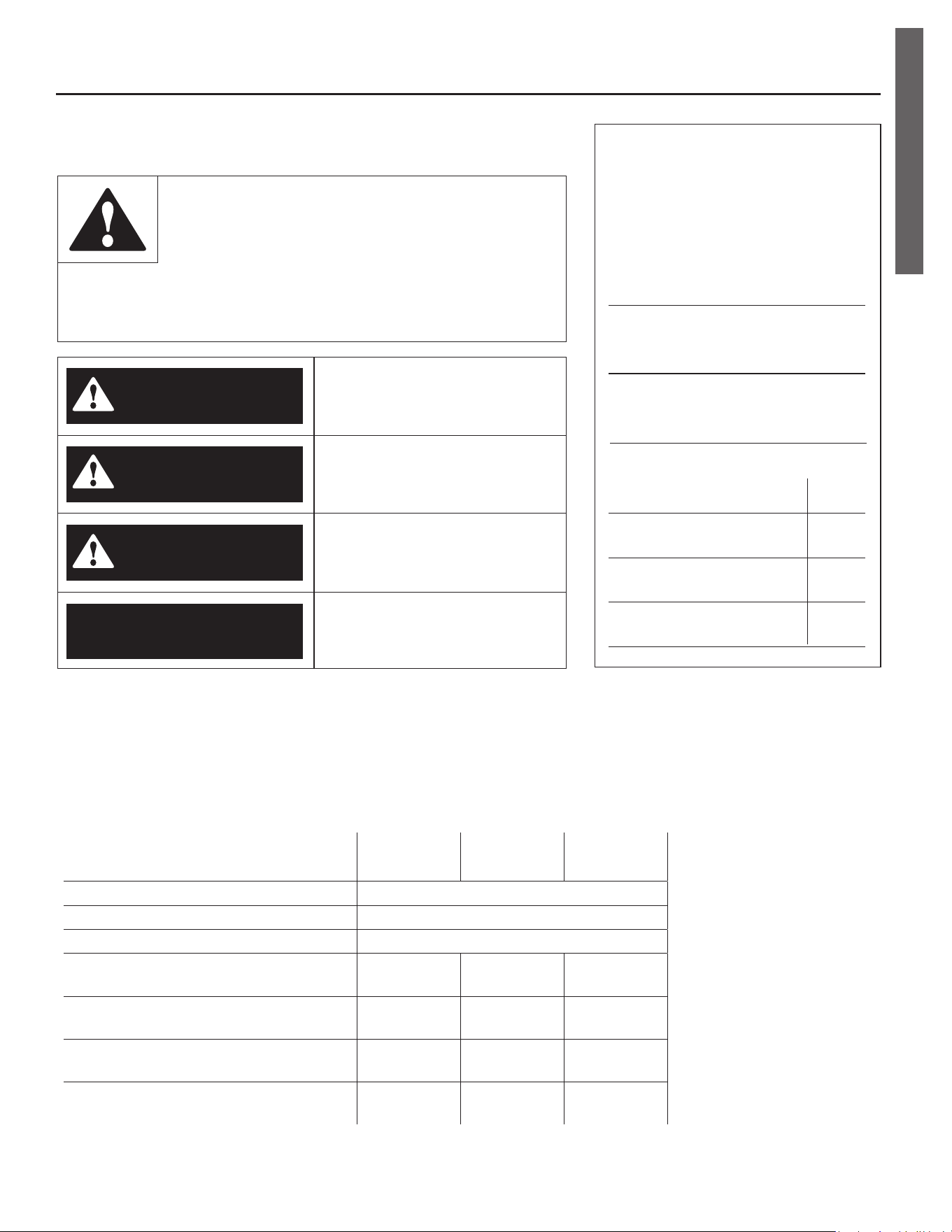
Figure 1 - Flexible connectors use compression
fittings and do not require soldering.
ON
OFF
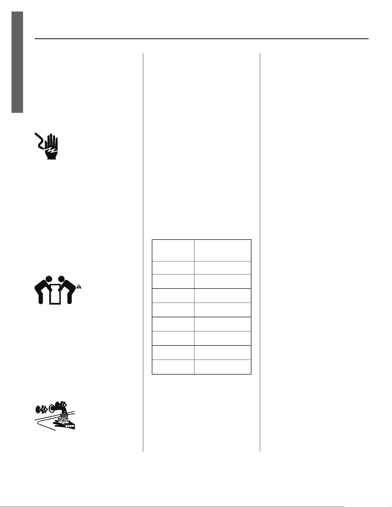
Figure 2 - Use a non-contact circuit tester to
insure that the power is off before you work on
a circuit.
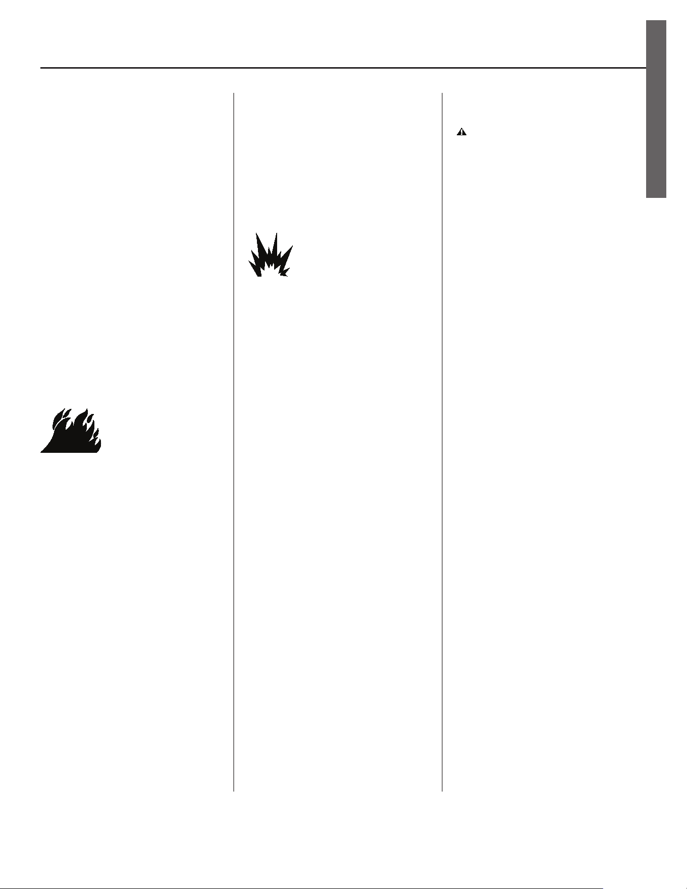
Figure 3 - Install a Pressure Reducing Valve set
to 50 to 60 PSI.
1
Review all of the instruc ons
before you begin work.
Improper installa on can
damage the water heater, your home
and other property, and can present
risks of serious injury or death.
2
Check with your local and
state authori es for any local
or state codes that apply to
your area. In the absence of local and
state codes, follow Na onal Fire
Protec on Associa on (NFPA-70) and
the current edi ons of the Na onal
Electric Code (NEC) and the Inter-
na onal Plumbing Code (IPC). The
instruc ons in this manual comply
with na onal codes, but the installer
is responsible for complying with local
codes.
Massachuse s code requires this wa-
ter heater to be installed in accordance
with Massachuse s 248-CMR 2.00 and
248-CMR 5.00: State Plumbing Code.
Other local and state authori es may
have similar requirements or other
codes applicable to the installa on of
this water heater.
3
Before you start, be sure you
have, and know how to use, the
following tools and supplies:
• Plumbing tools and supplies appropriate
for the type of water pipes in your home
• Threaded connectors (Figure 1) for
the cold and hot water pipes
• For homes plumbed with plas c
pipe, use threaded connectors
suitable for the specifi c type of
plas c pipe used: CPVC and PEX
(cross-linked polyethylene). Do
not use PVC pipe.
• For homes with copper pipes,
you may purchase connector kits
with compression fi ngs that
don’t require soldering (Figure
1). Compression fi ngs are
easier to install than soldering
copper pipes.
• Thread sealant tape or pipe joint
compound approved for potable
water
• Tools to make the electrical connec-
ons (for example, screwdrivers, wire
strippers)
• Non-Contact circuit tester to check
for power (Figure 2)
• Water Pressure Gauge (see next
page, Figure 4)
Recommended Accessories:
• Suitable drain pan (see Figure 6 on
page 8)
• Automa c leak detec on and shut-
off device
• Pressure Reducing Valve (Figure 3)
• Thermal Expansion Tank (see Figure 5
on page 7)
• Point-of-use Thermosta c Mixing
Valves (see Figure 7 on page 8).
Residen al Electronic Thermostat Electric Water Heater Use and Care Guide • 7
INSTALLATION
IMPORTANT: Follow these steps for
proper installa on:
Step 1:
✓
Verify that your
home is equipped
and up-to-date for
proper opera on
Installing a new water heater is the
perfect me to examine your home’s
plumbing system and make sure the
system is up to current code standards.
There have likely been plumbing code
changes since the old water heater was
installed. We recommend installing the
following accessories and any other
needed changes to bring your home up
to the latest code requirements.
Use the checklist below and inspect
your home. Install any devices you need
to comply with codes and assure that
your new water heater performs at its
best. Check with your local plumbing
offi cial for more informa on.
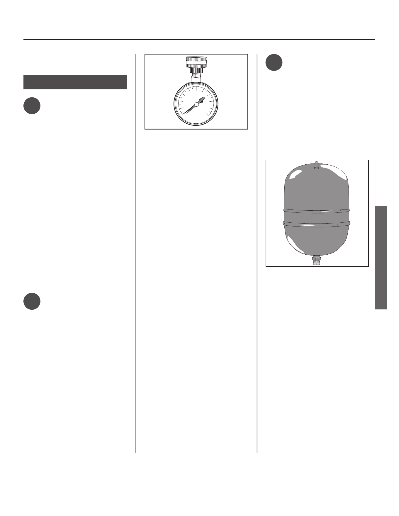
✓
Water pressure
We recommend checking your
home’s water pressure with a pressure
gauge (Figure 4). Most codes allow a
maximum incoming water pressure of
80 psi. We recommend a working pres-
sure no higher than 50-60 psi.
HOW: Purchase an inexpensive water
pressure gauge available at your local
plumbing supplier. Connect the Water
Pressure Gauge to an outside faucet
and measure the maximum water
pressure experienced throughout the
day (highest water pressures o en oc-
cur at night).
140
20
40
60
80
100
120
160
180
200
psi
AVOID FREEZING
Figure 4 - Use a Water Pressure Gauge to make
sure your home’s water pressure is not too high.
To limit your home’s water pressure:
Locate your home’s Pressure Reduc-
ing Valve (PRV) on the main incoming
(cold) water supply line and adjust the
water pressure control to between 50
and 60 psi. If your home does not have
a Pressure Reducing Valve, install a
PRV on the home’s main water supply
line and set it to between 50 and 60
psi. Pressure Reducing Valves are avail-
able at your local plumbing supplier.
BACKGROUND: Over the years, many
u li es have increased water sup-
ply pressures so they can serve more
homes. In some homes today, pres-
sures exceed 100 psi. High water
pressures can damage water heaters,
causing premature leaks. If you have
replaced toilet valves, had a water
heater leak, or had to repair applianc-
es connected to the plumbing system,
pay par cular a en on to your home’s
water pressure. When purchasing a
PRV, make sure the PRV has a built-in
bypass.
✓
Water pressure
increase caused by
thermal expansion
Verify that you have a properly sized
Thermal Expansion Tank (Figure 5). We
recommend installing an expansion
tank if your home does not have one.
Codes require a properly pressurized,
properly sized Thermal Expansion Tank
in almost all homes. (See image on
inside front cover.)
Figure 5 - A Thermal Expansion Tank helps pro-
tect the home’s plumbing system from pressure
spikes.
HOW: Connect the Thermal Expansion
Tank (available at your local plumbing
supplier) to the cold water supply line
near the water heater. The expansion
tank contains a bladder and an air
charge. To work properly, the Thermal
Expansion Tank must be sized accord-
ing to the water heater’s tank capacity
and pressurized to match the home’s
incoming water pressure. Refer to the
installa on instruc ons provided with
the Thermal Expansion Tank for instal-
la on details.
INSTALLATION
8 • Residen al Electronic Thermostat Electric Water Heater Use and Care Guide
INSTALLATION
BACKGROUND: Water expands when
heated, and the increased volume
of water must have a place to go, or
thermal expansion will cause large in-
creases in water pressure (despite the
use of a Pressure Reducing Valve on
the home’s main water supply line).
The Safe Drinking Water Act of 1974
requires the use of back fl ow preven-
ta ves and check valves to restrict
water from your home reentering
the public water system. Back fl ow
preventa ves are o en installed in
water meters and may not be readily
visible. As a result, most all plumbing
systems today are now “closed,” and
almost all homes now need a Thermal
Expansion Tank.
A Thermal Expansion Tank is a prac -
cal and inexpensive way to help avoid
damage to the water heater, washing
machine, dishwasher, ice maker and
even toilet valves. If your toilet oc-
casionally runs for no apparent reason
(usually briefl y at night), that may be
due to thermal expansion increasing
the water pressure temporarily.
Water pipe and tank
leaks
Leaks from plumbing pipes or from
the water heater itself can damage
property and could cause a fi re risk.
• Install the provided leak detector and
if included, the cold water shut-off
valve (see step 7, page 12). If a cold
water shut-off valve was not included,
one can be purchased at your local
plumbing supplier.
These devices can detect water leaks
and can shut off the water heater’s
water supply if a leak occurs.
Drain
Drain Pan
Leak Detection Sensor
Drain Pan
Discharge Pipe
Figure 6 - A suitable drain pan piped to an
adequate drain can help protect flooring from
leaks and drips.
• Install a suitable drain pan (available
in stores ) under the water heater
(Figure 6) to catch condensa on or
leaks in the piping connec ons or
tank. Most codes require, and we
recommend, installing the water
heater in a drain pan that is piped
to an adequate drain. The drain pan
must be at least two inches wider
than the diameter of the water
heater. Install the drain pan so the
water level would be limited to a
maximum depth of 1-3/4”.
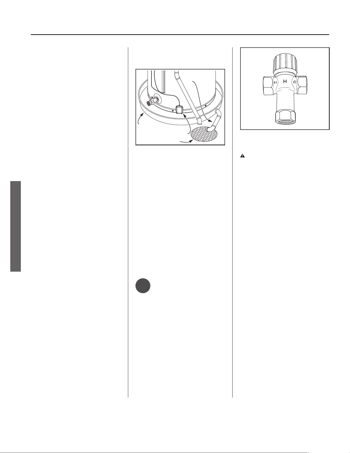
✓
Water tempera-
ture regula on
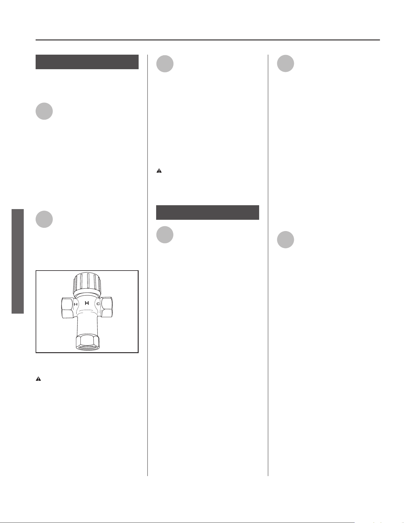
Install Thermosta c Mixing Valves
(Figure 7) to regulate the temperature
of the water supplied to each point-
of-use (for example, kitchen sink,
bathroom sink, bath, shower). Consult
the valve manufacturer’s instruc ons
or a qualifi ed person.
MIX
Figure 7 - Thermostatic Mixing Valves installed
at each point-of-use can help prevent scalding.
WARNING! Even if the water heater
thermostat is set to a rela vely low
temperature, hot water can scald.
Install Thermosta c Mixing Valves at
each point-of-use to reduce the risk of
scalding (see page 4 and Figure 7).
BACKGROUND: A Thermosta c Mix-
ing Valve, installed at each point-
of-use, mixes hot water from the
water heater with cold water to more
precisely regulate the temperature of
hot water supplied to fi xtures. If you
aren’t sure if your plumbing system
is equipped with properly installed
and adjusted Thermosta c Mixing
Valves at each point where hot water
is used, contact a qualifi ed person for
more informa on.
INSTALLATION
Residen al Electronic Thermostat Electric Water Heater Use and Care Guide • 9
Step 2:
Verify that the loca on
is appropriate
Before installing your water heater,
ensure that:
1
The water heater will be:
• Installed indoors close to the center
of the plumbing system.
• In a suitable drain pan piped to an ad-
equate fl oor drain or external to the
building (See Figure 6 on page 8).
• In an area that will not freeze
• In an area that is suitable for install-
ing the water heater ver cally.
2
The loca on has adequate
space (clearances) for periodic
servicing.
3
The fl oor can support the
weight of a full water heater.
4
Your area is not prone to
earthquakes. If it is, use
special straps as required by
local building codes.
NOTICE: The state of California re-
quires bracing, anchoring, or strapping
the water heater to avoid its moving
during an earthquake. Contact local
u li es for code requirements in your
area, visit h p://www.dsa.dgs.ca.gov,
or call 1-916-445-8100 and request
instruc ons. Other loca ons may have
similar requirements. Check with your
local and state authori es.
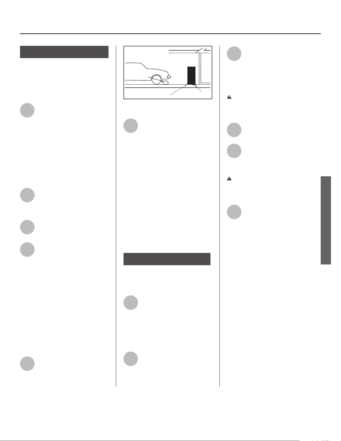
5
The loca on is not prone to
physical damage by vehicles,
fl ooding, or other risks.
Vehicle
Stop
Drain
Drain
Pan
Figure 8 - In a garage, install a vehicle stop to
avoid water heater damage.
6
Avoid loca ons such as a cs,
upper fl oors, or where a leak
might damage the structure
or furnishings. Due to the normal
corrosive ac on of water, the tank will
eventually leak. To minimize property
damage from leaks, inspect and
maintain your water heater in accor-
dance with this manual’s instruc ons.
Install a suitable drain pan under the
water heater piped to an adequate
drain. Inspect the drain pan, pipes, and
surrounding area regularly and fi x any
leaks found. Drain pans are available at
your local plumbing supplier. Leaks are
frequently in the plumbing system
itself and not the water heater.
Step 3:
Removing the old water
heater
1
Read each installa on step
and decide if you have the
necessary skills to install the
water heater. Only proceed if you can
safely perform the work. If you are not
comfortable, have a qualifi ed person
perform the installa on.
2
Locate the water heater’s
circuit breaker and turn it OFF
(or remove the circuit’s
fuses).
3
On the old water heater,
remove the electrical
junction box access panel.
Using a non-contact circuit tester,
check the wiring to make certain the
power is OFF.
WARNING! Working on an ener-
gized circuit can result in severe injury
or death from electrical shock.
4
Disconnect the electrical
wires.
5
Open a hot water faucet and
let the hot water run un l it is
cool (This may take 10
minutes or longer)
WARNING! Be sure the water runs
cool before draining the tank to reduce
the risk of scalding.
6
Connect a garden hose to the
drain valve and place the
other end of the hose in a
drain, outside, or a bucket. (Note that
sediment in the bo om of the tank
may clog the valve and prevent it
from draining. If you can’t get the
tank to drain, contact a qualifi ed
person.)
INSTALLATION
INSTALLATION
10 • Residen al Electronic Thermostat Electric Water Heater Use and Care Guide
INSTALLATION
7
Turn the cold water supply
valve OFF.
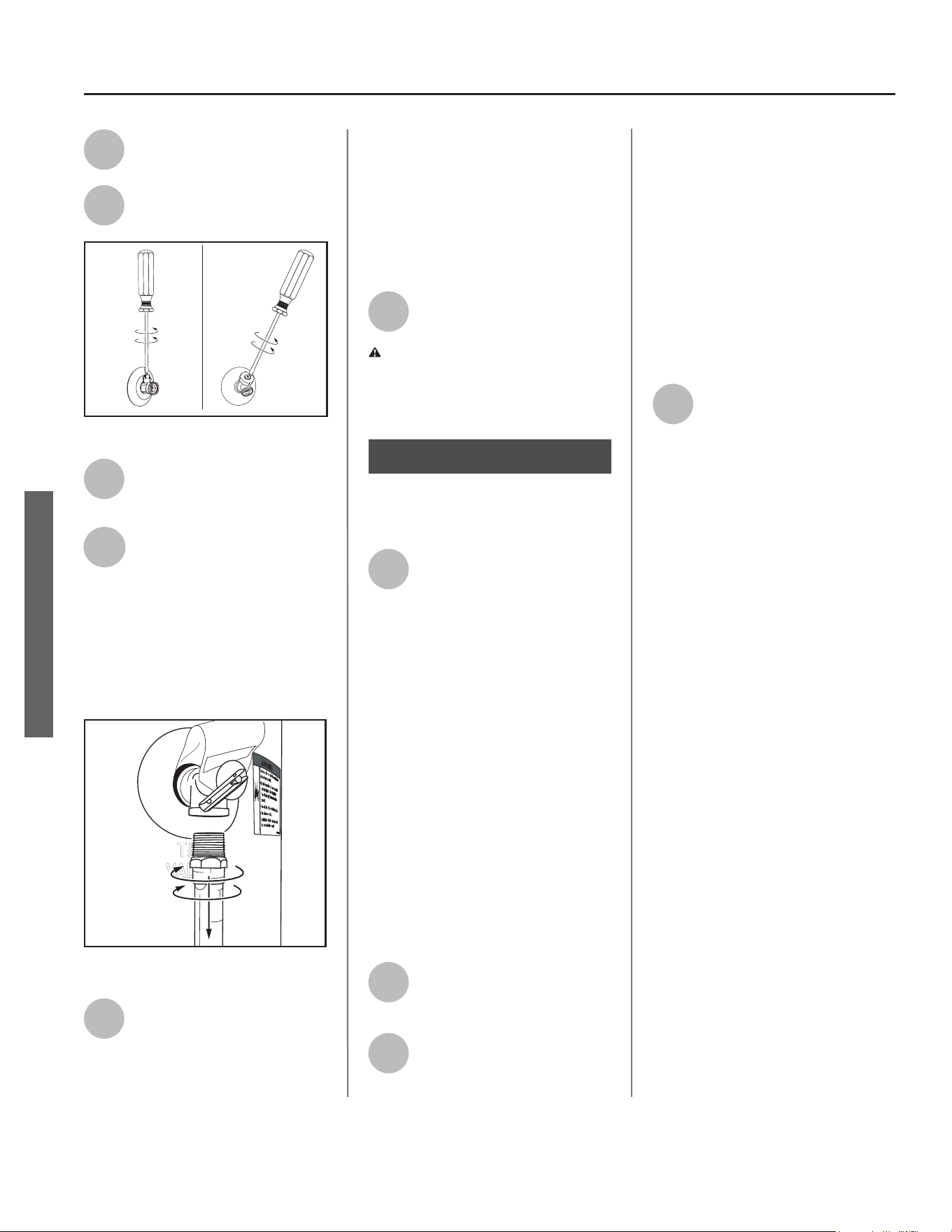
8
Open the drain valve on the
water heater.
Figure 9 - Draining the old water heater.
9
Also open a hot water faucet
to help the water in the tank
drain faster.
10
When the tank is empty,
disconnect the Temperature
& Pressure (T&P) Relief Valve
discharge pipe. You may be able to
reuse the discharge pipe, but do not
reuse the old T&P Relief Valve. A new
T&P Relief Valve comes installed on
your water heater (or on some models,
is in the carton with the water heater).
Figure 10 - Removing the T&P Relief Valve
discharge pipe.
11
Disconnect the water pipes.
Many water pipes are
connected by a threaded
union which can be disconnected with
wrenches. If you must cut the water
pipes, cut the pipes close to the water
heater’s inlet and outlet connec ons,
leaving the water pipes as long as
possible. If necessary, you can make
them shorter later when you install
the new water heater.
12
Remove the old water heater.
WARNING! Use two or more people
to remove or install water heater.
Failure to do so can result in back or
other injury.
Step 4:
Installing the new
water heater
1
Completely read all instruc-
ons before beginning. If you
are not sure you can com-
plete the installa on, DO NOT
RETURN THIS UNIT TO THE STORE.
Seek assistance from any of the
following sources:
• Professional Installa on is available
for this product and the work is
guaranteed. Contact a local plumb-
ing supplier to have this water
heater installed.
• Schedule an appointment with
a qualifi ed person to install your
water heater.
• Call our Technical Assistance Hotline
at 1-800-527-1953.
2
Install a suitable drain pan
that is piped to an adequate
drain.
3
Set the water heater in place
taking care not to damage
the drain pan.
NOTICE: Most codes require se ng
the water heater in a suitable drain
pan piped to an adequate drain. The
drain pan helps avoid property dam-
age which may occur from condensa-
on or leaks in the piping connec ons
or tank. The drain pan must be at
least two inches wider than the diam-
eter of the water heater. Install the
drain pan so the water level is limited
to a maximum depth of 1-3/4”.
4
Verify that the water heater
is set in place properly. Check
that:
• The T&P Relief Valve will not be in
contact with any electrical parts.
• There is adequate space to install
the T&P Relief Valve discharge pipe
and that it can be piped to a sepa-
rate drain (and not into the drain
pan).
• There is adequate access and space
around the water heater for future
maintenance.
INSTALLATION
DO NOT CONNECT ELECTRICAL
WIRING UNTIL YOU ARE
INSTRUCTED TO DO SO.
NOTICE: Connec ng electrical power
to the tank before it is completely
full of water (water must run FULL
STREAM from a hot water tap for a full
three minutes) may cause the upper
hea ng element to burn out.
Connect the Tempera-
ture and Pressure (T&P)
Relief Valve/Pipe
Most T&P Relief Valves are pre-installed
at the factory. In some cases, they are
shipped in the carton and must be
installed in the opening marked and
provided for this purpose and according
to local codes.
WARNING! To avoid serious injury
or death from explosion, install a T&P
Relief Valve according to the following
instruc ons:
1
If your water heater does not
have a factory installed T&P
Relief Valve, install the new
T&P Relief Valve that came with your
water heater. Do not reuse an old T&P
Relief Valve. Install a T&P Relief Valve
discharge pipe according to local codes
and the following guidelines:
• The discharge pipe should be at least
3/4” inside diameter and sloped for
proper drainage. Install it to allow
complete drainage of both the T&P
Relief Valve and the discharge pipe.
• The discharge pipe must withstand
250°F (121°C) without distor on. Use
only copper or CPVC pipe. Do not
use any other type of pipe, such as
PVC, iron, fl exible plas c pipe, or any
type of hose.
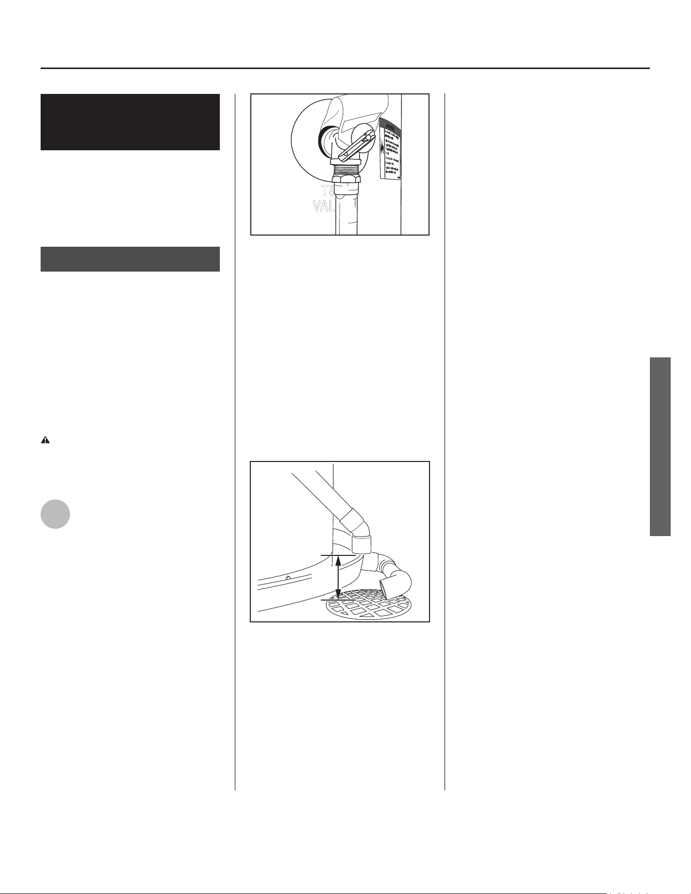
Figure 11 - The T&P Relief Valve discharge pipe
must be installed properly and piped to an
adequate drain.
• Terminate the discharge pipe a maxi-
mum of six inches above a fl oor drain
or outside the building. Do not drain
the discharge pipe into the drain
pan; instead pipe it separately to
an adequate drain. In cold climates,
terminate the discharge pipe inside
the building to an adequate drain.
Outside drains could freeze and
obstruct the drain line. Protect the
drain from freezing.
Figure 12 - The end of the T&P Relief Valve dis-
charge pipe must stop no more than six inches
above a floor drain or outside.
• Do not place any valve or other re-
stric on between the tank and T&P
Relief Valve. Do not cap, block, plug,
or insert any valve between the T&P
Relief Valve and the end of the dis-
charge pipe. Do not insert or install
any reducer in the discharge pipe.
Residen al Electronic Thermostat Electric Water Heater Use and Care Guide • 11
Step 5:
INSTALLATION
INSTALLATION
6.00"
MAX
Dicharge
Pipe
Drain
Pipe
Install shutoff and
tempering valves
1
If one is not already installed,
install a manual shutoff valve
in the cold water line that
supplies the water heater. Install the
shutoff valve near the water heater so
that it is readily accessible. Only use
valves that are compa ble with
potable water. Use only full-fl ow ball
or gate valves. Other types of valves
may cause excessive restric on to the
water fl ow.
2
Install a Thermosta c Mixing
Valve at each point-of-use
(for example, kitchen sink,
bathroom sink, bath, shower).
Consult the valve manufacturer’s
instruc ons or a qualifi ed person.
MIX
Figure 13 - Install Thermostatic Mixing Valves at
each point where hot water will be used.
WARNING! Even if the water
heater’s thermostat(s) are set to a
rela vely low temperature, hot water
can scald. Install Thermosta c Mixing
Valves at each point-of-use to reduce
the risk of scalding. (See page 4.)
3
For water heaters that are fed
by a solar water hea ng
system (or any other pre-heat-
ing system), always install a Thermo-
sta c Mixing Valve or other tempera-
ture limi ng device in the inlet water
supply line to limit water supply inlet
temperature to 120°F. Solar water
hea ng systems can supply water with
temperatures exceeding 170°F and
may result in water heater malfunc-
on.
WARNING! Hot water provided by
solar hea ng systems can cause
severe burns instantly, resul ng in
severe injury or death (see page 4).
1
Determine the type of water
pipes in your home. Most
homes use CPVC or cross-
linked polyethylene (PEX). Use fi ngs
appropriate for the type of pipe in
your home. Do not use iron or PVC
pipe – they are not suitable for
potable water.
The water inlet and outlet threaded
connec ons are brass. When
connec ng the unit to piping made of
a diff erent material, use of a dielectric
fi ng or a dielectric union conforming
to ASSE 1079 is recommended to
prevent corrosion and poten al
subsequent water leaks at or near the
connec on. Dielectric fi ngs may be
required by local plumbing codes.
IMPORTANT! A dielectric waterway
nipple is diff erent than a dielectric
nipple and does not perform the same
func on. A dielectric waterway nipple
will not protect the water heater from
corrosion.
2
Connect the cold water
supply using 3/4 inch
Na onal Pipe Thread (“NPT”)
to the BLUE cold water connec on on
the top side of the water heater.
To avoid damaging the smart valve,
use a pipe wrench at the hot and
cold nipples to counter torque
when installing or removing water
connec ons. DO NOT over ghten.
NOTICE: Some models come with a
cold water shut-off valve. This is to
be installed in the cold water line
near the water heater. Make sure the
module cable can be easily plugged
into the control assembly (within
30”). See included kit instruc ons
found with the automa c cold water
shut-off valve, for further installa on
instruc ons.
3
Connect the hot water supply
using 3/4 inch NPT to the
corresponding RED hot water
connec on on the top side of the
water heater. Follow the same
connec on guidelines as for the cold
water supply.
12 • Residen al Electronic Thermostat Electric Water Heater Use and Care Guide
INSTALLATION
Step 6:
Step 7:
INSTALLATION
Residen al Electronic Thermostat Electric Water Heater Use and Care Guide • 13
NOTICE: Most water heater models
contain energy saving heat traps in the
inlet and outlet connec ons to avoid
the circula on of hot water within the
pipes during standby. Do not remove
the heat traps.
4
Connect the hot water supply
using 3/4 inch NPT to the
fi ng marked “H” (HOT).
Follow the same connec on guidelines
as for the cold water supply.
5
Install insula on (or heat
tape) on the water pipes
especially if the indoor
installa on area is subject to freezing
temperatures. Insula ng the hot water
pipes can increase energy effi ciency.
6
Double check to make sure
the hot and cold water pipes
are connected to the correct
hot and cold water fi ngs on the
water heater.
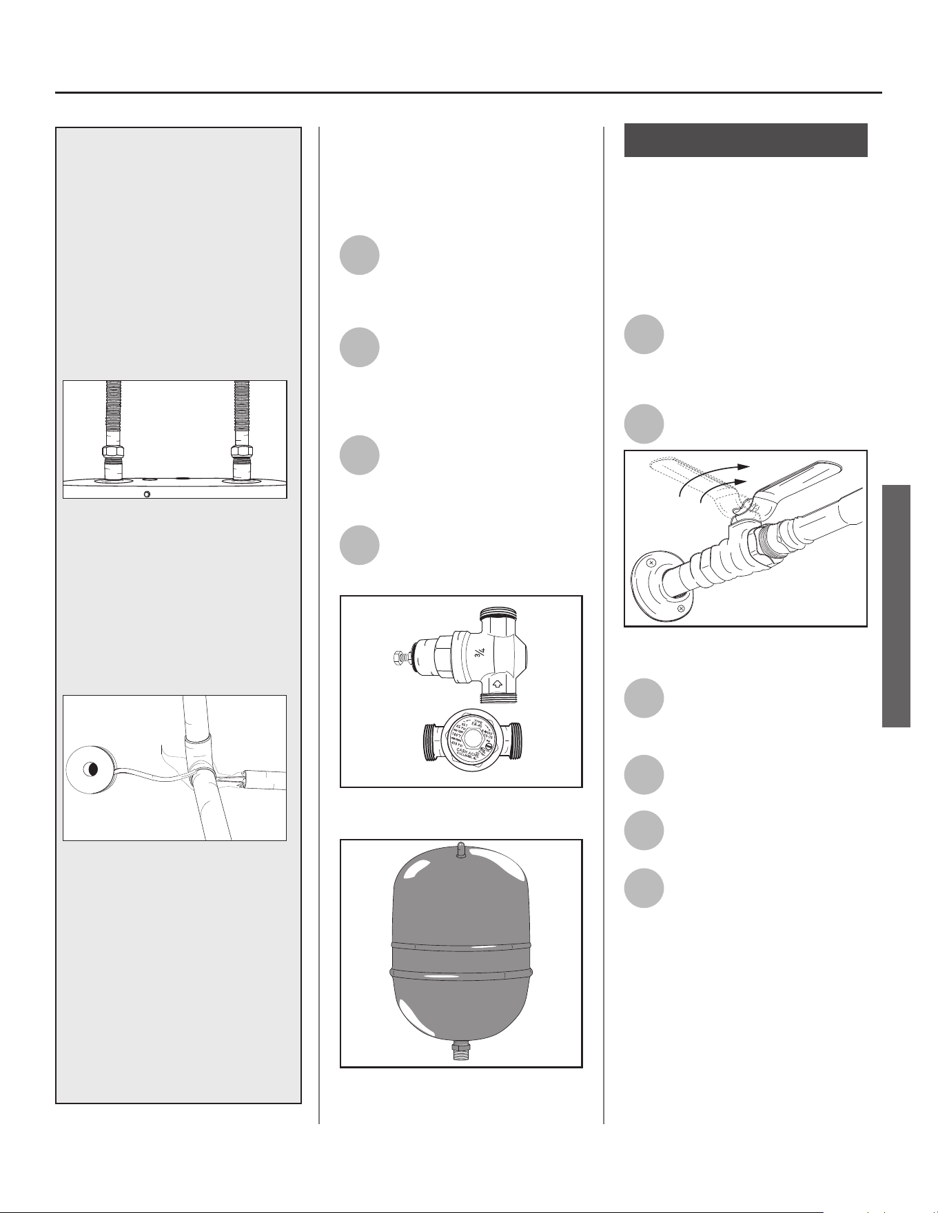
7
If needed, install (or adjust)
the home’s Pressure Reducing
Valve to 50-60 psi and install a
Thermal Expansion Tank.
Figure 14 - A Pressure Reducing Valve is required
if your home’s water pressure is above 80 psi.
Figure 15 - The Thermal Expansion Tank should
be pressurized with air, to match the home’s
incoming water pressure.
Step 8:
Verify connec ons and
completely fi ll tank
To remove air from the tank and allow
the tank to fi ll completely with water,
follow these steps:
1
Remove the aerator at the
nearest hot water faucet. This
allows any debris in the tank
or plumbing system to be washed out.
2
Turn the cold water supply
back on.
Figure 16 - Fully open the cold water supply
valve.
3
Open a hot water faucet and
allow the water to run un l it
fl ows with a full stream.
4
Let the water run full stream
for three full minutes.
5
Close the hot water faucet
and replace the aerator.
6
Check inlet and outlet
connec ons and water pipes
for leaks. Dry all pipes so that
any drips or leaks will be apparent.
Repair any leaks. Almost all leaks occur
at connec ons and are not a tank leak.
INSTALLATION
INSTALLATION
IF YOU HAVE COPPER PIPES:
If your home has copper water
pipes, you can solder the water pipe
connec ons or use compression
fi ngs which do not require
soldering. Compression fi ngs
are easier to install than soldering
pipe. Check with local plumbing
offi cials to determine what types of
pipe materials are suitable for your
loca on. Do not use lead-based
solder.
Compression fi ngs don’t require soldering.
NOTICE: Do not solder pipes while
they are a ached to the water
heater. The water heater’s inlet
and outlet connec ons contain
non-metallic parts which could be
damaged. The proper way to connect
the water heater to copper water
pipes is as follows:
Solder a short length of pipe (about
a foot or so) to a threaded adapter
using only 95/5 n-an mony
or equivalent solder. A ach the
threaded adaptors to the water
heater’s connec ons (using
thread sealant tape or pipe joint
compound). Connect the home’s
water pipes by soldering, keeping the
connec ons at the water heater cool
with wet rags. DO NOT over apply
joint compound.
14 • Residen al Electronic Thermostat Electric Water Heater Use and Care Guide
INSTALLATION
Make electrical
connec ons
WARNING! Working on an ener-
gized circuit can result in severe injury
or death from electrical shock.
NOTICE: Although this water heater is
equipped with Dry-Fire protec on, be
sure the tank is completely fi lled with
water and all the air is purged from
the tank, before making any electrical
connec ons.
1
Be sure the electrical power
to the water heater is turned
OFF at the circuit breaker
panel (or remove the circuit’s fuses).
2
Using a non-contact circuit
tester, check the wiring to
make certain the power is OFF.
3
Check the water heater’s
data plate and ensure that
the home’s voltage, wiring
size (ampacity) and circuit breaker
ra ng and type are correct for this
water heater. Refer to the wiring
diagram located on the water heater
for the correct electrical connec ons.
Ensure that wire sizes, type, and
connec ons comply with all appli-
cable local codes. In the absence of
local codes, follow NFPA-70 and the
current edi on of the Na onal Electric
Code (NEC).
4
Remove the cover on the
electrical junc on box on the
top of the water heater.
DATA PLATE
Figure 17 - The water heater’s electrical require-
ments can be determined from the data plate.
5
Install wiring in an approved
conduit (if required by local
codes). Use a UL listed or CSA
approved strain relief to secure the
electrical wiring to the water heater.
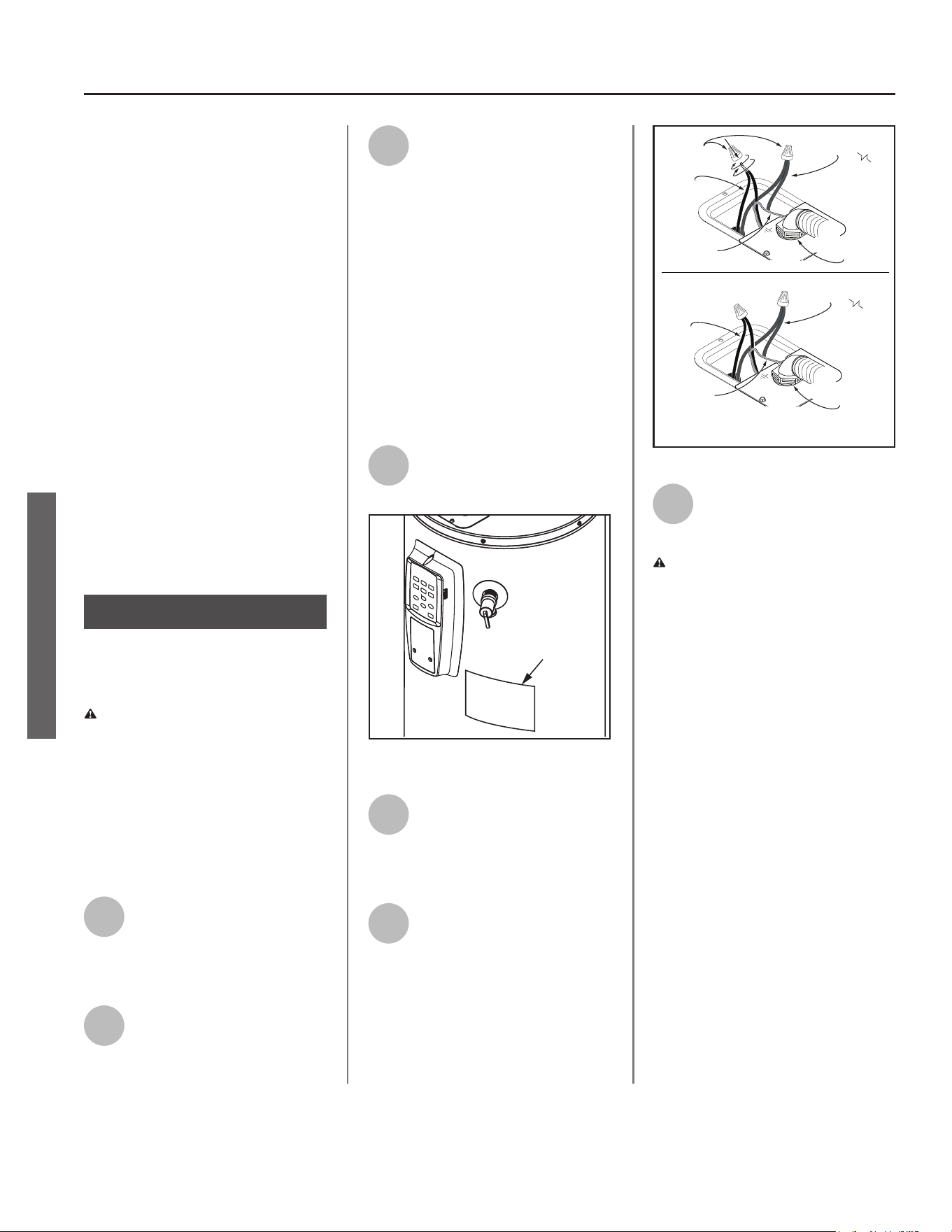
6
Connect the ground wire to
the green ground screw.
Connect the home’s two
power wires to the water heater’s two
power wires (black to black, red to
red). Use suitable twist-on wire
connector or other approved means
to make the power connec ons.
Red Wires
Ground
Wires
Black Wires
Red Wires
Ground
Wires
1/2” Conduit
Connection
Black Wires
Wires
Connectors
Connection
1/2” Conduit
Figure 18 - Connecting the electrical wires.
7
Replace the junc on box
cover and secure with the
screws provided.
WARNING! Be sure cover is secured
to reduce the risk of fi re and electric
shock.
NOTICE: The tank must be completely
empty of air and full of water before
connec ng electrical power to avoid
“Dry Firing.” Dry Firing may result in
the upper element burning out. This
is a common installa on mistake. Af-
ter you make the water connec ons,
but before you connect the electrical
power, open a hot water faucet and
let the water run full un l all the air
is removed. Let the “hot” water run
full for three minutes or longer before
connec ng any electrical wires. A Dry
Fired upper hea ng element is an
installa on error and is not covered
under warranty.
This model is equipped with Dry-Fire
protec on, which will ac vate an
error code if the above steps are not
fully followed.
Step 9:
INSTALLATION
Residen al Electronic Thermostat Electric Water Heater Use and Care Guide • 15
INSTALLATION
Step 10:
Installing the Leak
Detec on Sensor
The leak detect sensor LDS does not
provide protec on against a water
leak, it only provides no fi ca on that
water is present in the loca on of the
sensor. When a leak is detected the
control assembly will display an error
code accompanied by a fl ashing light
and audible signal. If the presence of
water is indicated disconnect power to
the water heater, turn off the incom-
ing water off and address the source
of the leak before returning the unit to
service. See included kit instruc ons
found with the LDS, for detailed instal-
la on instruc ons.
1
Connect the LDS to the lower
door connector.
2
A ach the LDS to the heater
or drain pan using the tape on
the back of the LDS. Ensure
the metal probes point down.
3
Use the included wire clamps
to organize the wires.
Step 11:
Adjus ng the
Temperature
With the installa on steps completed,
you may adjust the water heater’s
temperature se ng if desired.
WARNING! Be sure panels are
secured to reduce the risk of fi re and
electric shock.
1
Turn the electric power back
on.
2
Set the thermostat to the
desired temperature, on the
control assembly. See
“Adjus ng the Control Assembly’s
Opera onal Modes,” page 17. The set
point on this water heater has been
factory set to approximately 120°F to
reduce the risk of scald injury. You may
wish to set a higher temperature to
provide hot water for automa c
dishwashers or laundry machines, to
provide more hot water capacity, and
to reduce bacterial growth. Higher
tank temperatures (140° F) kill
bacteria that cause a condi on known
as “smelly water” and can reduce the
levels of bacteria that cause water-
borne diseases.
WARNING! Higher temperatures
increase the risk of scalding, but even at
120°F, hot water can scald (see page 4).
If you increase the water heater’s tem-
perature se ng, install Thermosta c
Mixing Valve(s) at each point-of-use to
reduce the risk of scalding.
MIX
Figure 19 - Adjust Thermostatic Mixing Valves at
each point-of-use to 120°F or lower.
WARNING! Working near an
energized circuit can result in severe
injury or death from electrical shock.
Check wires with a circuit tester to
make sure power is off .
3
Wait for the water to heat up.
It may take several hours for a
tank of cold water to heat up.
If you have no hot water a er two
hours, refer to the “Troubleshoo ng
Sec on,” page 22.
WARNING! If you have increased
the temperature se ng and the
Thermosta c Mixing Valves are not set
properly (or not installed) you could
scald yourself while checking the
temperature.
4
Check water temperature at
several points of use in your
home (for example, bathtub
faucet, shower, or lavatory sink) and
adjust the Thermosta c Mixing Valves
as needed. If you aren’t sure how to
adjust the Thermosta c Mixing Valve
se ngs, or aren’t sure if you have
Thermosta c Mixing Valves, contact a
qualifi ed person.
Step 12:
Opera on
Remove/pull out the battery protec-
tive tab from the left side of the con-
trol assembly. The water heater is now
ready for normal operation. To keep
your water heater working safely and
efficiently and extend its life, perform
maintenance according to the sug-
gested maintenance schedule. See
“Maintenance,” page 25.
Turn the electric power on at the
circuit breaker panel, or fuse box.
Power to the water heater will allow
the water heater to run a system diag-
nostic. This typically takes a few min-
utes. Once complete, proceed to the
Operations section of this manual.
NOTICE: If the system diagnostic yields
any codes, reference the diagnostic
codes section in this manual.
INSTALLATION
16 • Residen al Electronic Thermostat Electric Water Heater Use and Care Guide
OPERATION
INSTALLATION
General Opera on
(Control Assembly)
IMPORTANT: On the ini al start up
of the unit, the water heater will go
through a seven (7) to ten (10) minute
diagnos c period prior to hea ng the
water.
NOTICE: If the water is warm/hot, the
unit will not go through the diagnos c
period.
The primary func on of the control
assembly is to heat the water in
the tank un l it reaches the Control
setpoint. The control assembly has
two means of hea ng the water, the
upper element and the lower element.
A er reaching the control setpoint, the
temperature in the tank is allowed to
drop a pre-determined amount before
the elements are turned on again.
At any given me, the control assembly
only energizes one element at a me.
NOTICE: The control logic of the
control assembly is designed so that
the upper hea ng element will always
have priority over the lower hea ng
element when both elements call for
heat. The temperature regula on will
not performed un l a er the Dry-Fire
detec on tes ng indicates that there is
suffi cient water in the tank.
Vaca on Mode (Control
Assembly)
To save energy, lower the
temperature setting on the
thermostat if you plan to be gone for
an extended time.
Follow the instructions in Step 11
for adjusting the thermostat to a
lower temperature setting before
you leave and to properly raise the
temperature setting when you return.
See “Adjus ng the Control Assembly’s
Opera oal Modes,” page 17.
NOTICE: Vacation/Cabin mode has a
fixed set point of 50°F.
The default vacation days are preset
at 7 days. The vacation days can be
adjusted between 1 ~ 99 and so on.
To adjust the days, press the
VACATION button followed by the Up/
Down buttons. To confirm the desired
settings, press the Enter button.
When the vacation days decrease
to 8 hours remaining, the control
assembly will automatically switch to
STANDARD mode.
NOTICE: Normally the display will
only show the remaining vacation
days.
C AUTION! Hydrogen gas builds up
in a hot water system when it is not
used for a long period (two weeks
or more). Hydrogen gas is extremely
fl ammable. If the hot water system
has not been used for two weeks or
more, open a hot water faucet for
several minutes at the kitchen sink
before using any electrical appliances
connected to the hot water system.
Do not smoke or have an open fl ame
or other igni on source near the
faucet while it is open.
Hot Water+ Mode
This feature increases the amount
of usable hot water available to
be er match your daily needs. It
stores addi onal thermal energy by
increasing the temperature of the
water in the tank. As hot water is
drawn from the tank the integrated
smart valve combines with cold
water to mix to the desired water
temperature set on the controls.
By default, this func on is
deac vated, but can be enabled to
three increasing levels of performance
using the Hot Water+ Mode bu on
on the Control Assembly (Figure
20). Hot Water+ Mode is op mized
for the factory 120°F/49°C outlet
water temperature se ng and will
have decreasing benefi ts as the set
temperature is increased.
When Hot Water+ Mode is ac vated,
the LED indicator for the selected
opera ng mode will remain lit.
Guest Mode
This mode maximizes the amount of
hot water available for holidays or
other mes with higher than normal
hot water usage. It stores addi onal
thermal energy by increasing the
temperature of the water in the tank.
As hot water is drawn from the tank
the integrated smart valve combines
with cold water to mix to the desired
water temperature set on the
controls.
When Guest Mode is selected, the
dura on mer will be displayed. The
default Guest Mode days are preset
at 3 days dura on. Press the Up and
Down bu ons to modify the mer to
the desired number of Guest Mode
days (se ng range: 1 to 7 days). The
mer will blink on the display; press
the Mode/Enter bu on to confi rm the
Guest Mode mer. The water heater
will revert to the previous opera ng
mode when the dura on has expired.
NOTICE: Opera ng the water heater
in Guest Mode may increase energy
consump on.
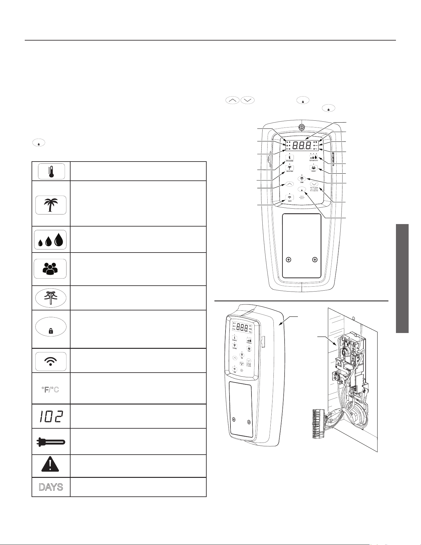
Opera ng Mode Descrip ons
If locked, the opera ng modes can be changed by holding the
ENTER
bu on for approximately 3 seconds, then touching the
desired mode icon on the control assembly. See Figure 20.
STANDARD - Pressing this bu on will allow the
temperature set point to be set directly.
VACATION MODE - The controller adjusts the
set point to approximately 50
0
F. This mod e is
recommended when the water heater is not
in use for a long period of me. This mode
minimizes energy consump on and prevents the
water heater from freezing during cold weather.
HOT WATER+ MODE - Allows the user to
enable three levels of increasing performance
while maintaining the temperature set point.
GUEST MODE - Provides maximum
performance and capacity for higher than
normal hot water usage. Selec ng this mode
may increase energy consump on.
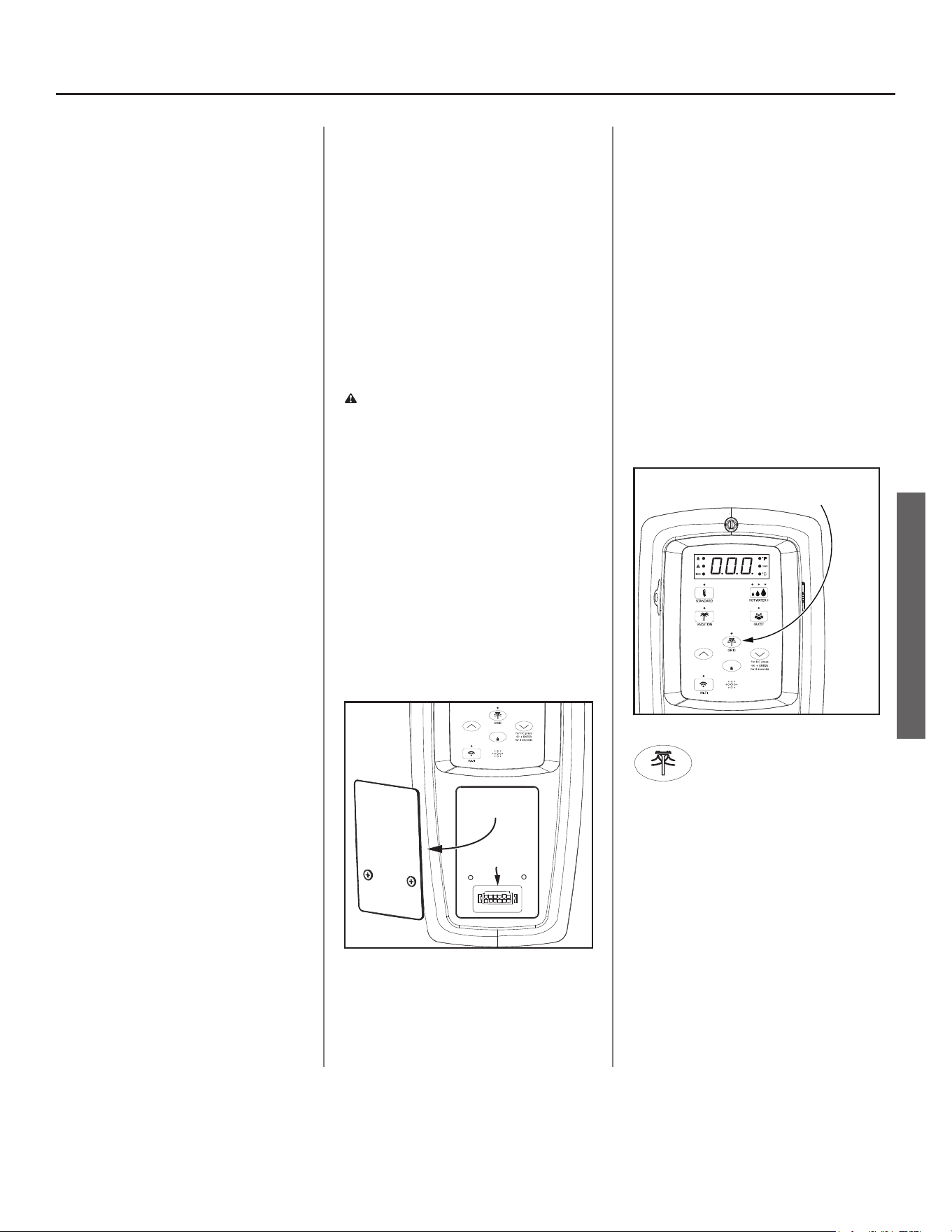
SMART GRID CONTROL - Pressing this bu on
will enable or disable a request for grid control.
See page 19.
ENTER
CONTROL ASSEMBLY LOCK - Holding this bu on
for more than 3 seconds switches the lock mode
on or off . When the User Module is locked, a
symbol and “Lock” text will be visible on the
display.
Wi-Fi - Press the Wi-Fi button once to activate
the Wi-Fi signal. The signal will turn off after
15 min of inactivity.
0
F/
0
C - This bu on, when pressed in combina-
on with the “Enter” bu on switches the display
to show the set temperature in Fahrenheit or
Celsius.
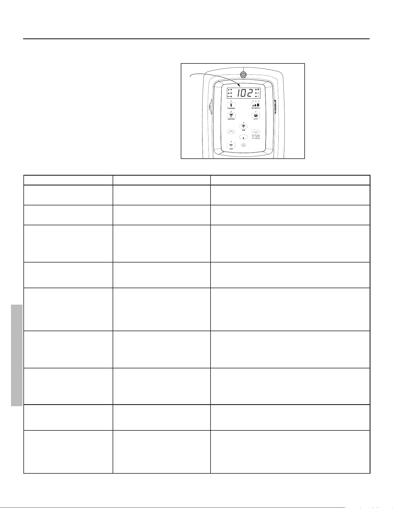
Fault condi on will display a three digit fault
code with Alert Icon fl ashing. See “Control
Assemble Diagnos c Code Chart,” page 20.
HEATING CYCLE ICON - Indicates the water
heater is in a hea ng cycle and the elements are
energized.
ALERT INDICATOR - Indicates when there is a
Warning/Fault.
DAYS
DAYS - Indicates the number of days (1 to 99+)
the unit will be in vaca on mode are being set.
Adjusting the Control Assembly’s Operational Modes
Water Temperature Adjustment
IMPORTANT: On the ini al start up of the unit, the water heater will go through a seven (7) to ten (10) minute diagnos c period
prior to hea ng the water. Before a emp ng to adjust the thermostat, read the “Important Safety Informa on,” page 4. If the instruc-
ons are not clear, contact a qualifi ed service technician.
The water temperature can be adjusted from 95° F to 150° F by pressing the followed by the
ENTER
bu on to lock in the desired
temperture. The control assembly is unlocked by default, to lock the display a er se ng the parameters, press the
ENTER
bu on.
Residen al Electronic Thermostat Electric Water Heater Use and Care Guide • 17
INSTALLATION
°C
DAYS
ENTER
Control Assembly
Lock LED Indicator
Heating
Cycle
LED Indicator
Water Temperature
Set Point
Temperature
Down (Decrease)
Button
Temperature
Up (Increase)
Button
LCD Display Panel
Lock Button
Control
Assembly
Top
Thermostat
/ECO
Wi-Fi
Button
Grid Enabled
Button W/LED
Indicator
Vacation Mode
Button
Celsius LED
Indicator
Fahrenheit LED
Indicator
Standard
Button
Days LED
Indicator
Alert
Indicator
Hot Water+ Mode
Button
Guest Mode
Button
Figure 20 - Control Assembly
OPERATION
°C
°F/
18 • Residen al Electronic Thermostat Electric Water Heater Use and Care Guide
INSTALLATION
18 • Residen al Electronic Thermostat Electric Water Heater Use and Care Guide
OPERATION
Wi-Fi (Control
Assembly)
This water heater comes equipped
with the iCOMM™ remote monitoring
system. It allows users to monitor
critical operations and diagnose issues
remotely using the manufacturer’s
water heater app (available for IOS
and Android).
The iCOMM™ system can
automatically notify selected
personnel via email and/or cellular
phone text messages if operational
problems occur.
It is recommended the water heater
app be installed on the homeowner’s
device prior to setting up the Wi-Fi
function on this water heater.
IMPORTANT: By enabling and
connecting your water heater to
Wi-Fi, you are granting permission
to the manufacturer to push “over-
the-air” (OTA) updates to the water
heater and to collect telemetry data
regarding the water heater. The OTA
updates may be pushed periodically
to address bugs and provide security
patches. Refer to the Terms and
Conditions at www.aosmith.com/
Utility-Pages/Terms-and-Conditions/
for more details. Also, refer to www.
aosmith.com/Privacy-Policy/ for
more information about how we
collect and use data.
Wi-Fi Set Up
The Wi-Fi signal is set to Off by default
and will not produce a signal until
activated.
NOTICE: Have the router SSID and
password ready.
• Download the iCOMM U li es
app for your smart phone.
• Launch the iCOMM U li es app
on your smart phone, then follow
the simple steps. The iCOMM
U li es app makes it easy to set
up, program and control your
Water Heater.
• Create an account or log in to
your exis ng account and tap the
“add a water heater” bu on.
• When the app prompts you to
ac vate the Wi-Fi signal proceed
with the following steps:
1
To activate the Wi-Fi signal,
press the Wi-Fi button once.
The LED will blink on and off in
0.5 second intervals. Wi-Fi will
activate pairing mode (Figure 21).
°C
DAYS
ENTER
Pressing the Wi-Fi button once will activate
the Wi-Fi signal for 15 minutes.
Figure 21 - Wi-Fi Control
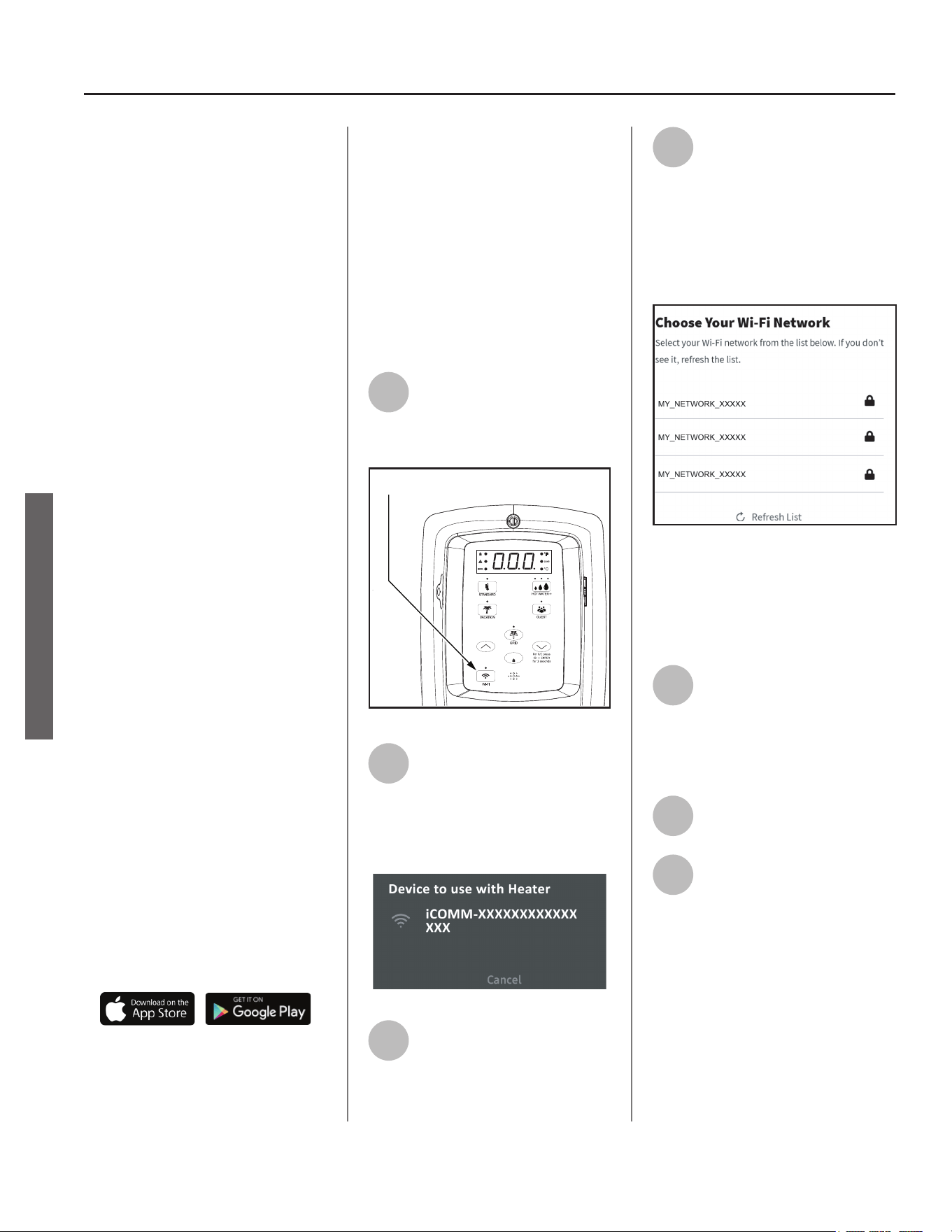
2
The app will display a
temporary Wi-Fi network to
connect to your device. Select
the network that matches the water
heater DSN value, and your device will
connect to the Wi-Fi radio an the
Control Assembly:
Figure 22 - Select Temporary Network
3
The app will begin the
communica on process of
linking your water heater to
your Wi-Fi router.
4
Select your preferred
Wi-Fi network from the list on
the app. LED will pulse from
dim to bright, when attempting to
connect to local network. If the app
does not prompt you with a list of
available Wi-Fi networks, access Wi-Fi
se ngs on your device and select your
preferred network.
Figure 23 - Select Your Wi-Fi Network
NOTICE: Your water heater does not
support the following:
• 5GHz Wi-Fi
• WPA3 Security Protocal
5
The app will a empt to
connect with your Wi-Fi
network. We recommend
connec ng to a Wi-Fi network that
has been secured with a password.
The LED will hold solid when
connected.
6
The app will display your water
heater’s se ngs.
7
Confi gure your water heater’s
Set Point, Mode, and Time of
Use Rate Plan if applicable.
NOTICE: If the Wi-Fi signal is to be
terminated, press and hold the Wi-Fi
button for 3 seconds. The Control
Assembly will beep once. This will
turn the Wi-Fi signal off. The Control
Assembly resets and the LED display
will turn off. Press and hold the Wi-Fi
button for 9 seconds to remove the
original connected network from the
Control Assemby memory.
Residen al Electronic Thermostat Electric Water Heater Use and Care Guide • 19
Smart Grid Technology
The electric Smart Grid will enable
signifi cant improvements in electric
power reliability and quality through
reduc on of peak power demand, while
providing consumers the knowledge
and ability to manage their energy
consump on and u lity costs.
According to the Department of
Energy (DOE), since 1982 the growth
in peak electricity demand has
exceeded power transmission growth.
This has caused more frequent
blackouts and service interruptions,
as well as an increase in the costly
reserve capacity the power grid
requires to meet higher peak
demands. The increased demand for
electrical power across the nation has
also led to higher peak utility costs.
Smart appliances are one way to
help mitigate this problem. By using
advanced digital communication
technologies, smart appliances will
be able to communicate with local
power company or home energy
management systems, and react
accordingly to save energy and money.
For example, during peak demand
periods the water heater may pause
or delay its power consumption
and thus reduce the load on the
smart utility grid. Additionally, smart
appliances will also communicate with
consumers to let them know how
much energy they are consuming.
This will eventually allow consumers
to control their appliances, manage
energy usage, and to ultimately save
money.
Home Automa on,
Smart Grid Control
(Where Available)
Where available, grid communica on
adaptors called Unitary Control Modules
(UCM) may be supplied by the local
power company or purchased from
leading retailers. A UCM is a direct digital
thermostat that provides integrated
control of the units thermostat. Please
contact your local power company for
more informa on.
WARNING! Electrical Shock Hazard
Disconnect power before servicing.
Replace all parts and panels before
opera ng. Failure to do so can result in
death or electrical shock.
To ac vate Smart Grid Control, Turn
“OFF” electric power to the water
heater at the circuit breaker/fuse box.
Using a non-contact circuit tester, check
the power wires to make certain the
power is OFF. Remove the cover over
the grid connec on pins and plug in the
UCM grid communica on adaptor and
return power to the water heater at the
circuit breaker/fuse box. See Figure 24.
ENTER
Remove
Panel
Grid Connection Pins
Figure 24 - Accessing Smart Grid Connection Pins
NOTICE: Use only approved grid
communica on adaptors. This
will enable the power company to
communicate the peak demand periods
for the water heater’s power usage.
A er this connec on has been made,
the grid control is automa cally enabled.
Press Enter to confi rm UCM is present.
This ac on will be followed by a solid
LED from the grid indicator. See Figure
25.
Enabling this feature will allow
acceptance of the power company
communica on of grid management
requests.
NOTICE: The LED will blink when the
power company has control of the unit.
°C
DAYS
ENTER
Pressing the Smart Grid Control
button will enable and/or disable
a request for grid control.
Figure 25 - Smart Grid Control Button
To disable (override) grid
control, press the Smart Grid
Control bu on. This ac on will be
followed by a 72 hour mer. Remove
CTA 2045 UCM. Press Enter to confi rm
the disconnec on. The LED will turn off .
NOTICE: If the CTA 2045 UCM is not
removed followed by the pressing the
Enter bu on, the grid will be enabled
automa cally once the 72 hour mer
has ended.
INSTALLATION
OPERATION
CONTROL ASSEMBLY DIAGNOSTIC CODE CHART
ERROR CODE INDICATES CORRECTIVE ACTION*
No Error Code Displayed
Not Enough Hot Water
High usage, plumbing leak, operating mode
adjustment.
1. Check for plumbing leak.
2. Adjust temperature; see scald warnings on heater and in manual.
3. Contact a qualified person to perform a volume test.
No Error Code Displayed
Water Too Hot
Water temperature set too high or grounded
element.
1. Reduce temperature setting.
2. Contact a qualified person to test for the grounded element and replace
if necessary.
No Error Code Displayed
No Hot Water
No power, control panel or thermostat opera-
tion
1. Turn off electrical power at breaker.
2. Unplug and reconnect 24 pin connector.
3. Turn on electrical power at breaker
4. Contact a qualified person to verify correct voltage to unit.
NOTICE: If the control panel was not connected via WiFi the time will need
to be set.
001 with an alert indicator flashing.
(also flashing red LED and beeper.)
Dry-fire, electrical power on with the tank not
completely full of water.
1. Turn off electrical power at breaker. Add water, open a hot water faucet
to bleed all air until water flows without air bursts.
2. Turn on electrical power at breaker.
3. See “Important Safety Information,” page 4.
002 with an alert indicator flashing.
(also flashing red LED and beeper.)
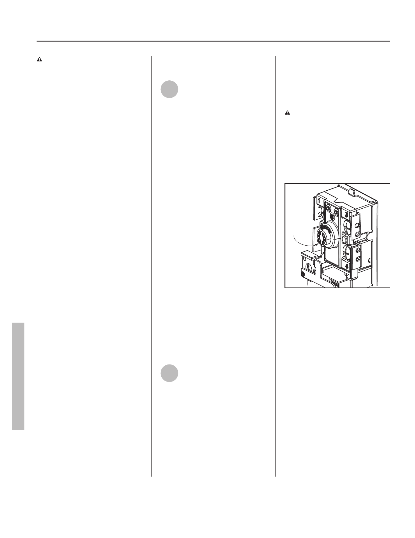
Water temperature exceeded high limit. ECO 1. Turn off electrical power at the breaker.
2. Press the reset button. See Figure 27.
3. Turn on electrical power at breaker.
4. If error returns contact a qualified technician to test for the grounded
element. Replace as needed.
5. If both elements test good, replace the upper thermostat.
6. Turn on electrical power at breaker.
003 with an alert indicator flashing.
(also flashing red LED and beeper.)
Upper thermistor sensor failure.
NOTICE: Upper thermistor sensor is part of
the thermostat.
1. Turn off electrical power at the breaker.
2. Check electrical connections at thermostat.
3. If there are no issues with the wiring, replace the thermostat.
4. Turn on electrical power at breaker.
NOTICE: The control panel will go into Limp Mode until the failure is
corrected. See page 22.
004 with an alert indicator flashing.
(also flashing red LED and beeper.)
Lower thermistor sensor failure.
NOTICE: Lower thermistor sensor is part of
the thermostat.
1. Turn off electrical power at the breaker.
2. Check electrical connections at thermostat.
3. If there are no issues with the wiring, replace the thermostat.
4. Turn on electrical power at breaker.
NOTICE: The control panel will go into limp mode until the failure is
corrected. See page 22.
006 with an alert indicator flashing.
(also flashing red LED and beeper.)
Internal Processor Error
- Frequency Fault
- Standard AD Reference Fault
- Non-Volatile Memory Fault
1. Turn off electrical power at the breaker. Now turn on electrical power to
see if error clears. If error has not cleared, replace the control assembly.
2. Turn on electrical power at breaker.
021 with an alert indicator flashing.
(also flashing red LED and beeper.)
Upper element circuit failure.
NOTICE: Lower element is still operable.
1. Turn off electrical power at the breaker.
2. Check element circuits for resistance of 5-25 ohms (replace if required).
3. Check wires at elements and thermostat for damage.
4. Turn on electrical power at breaker.
5. If the error persists, contact a qualified person.
NOTICE: The control assembly will go into limp mode until the failure is
corrected. See page 22.
IMPORTANT: Before attempting to adjust the ther-
mostat, read the “Important Safety Information”
section page 4.
If the instructions are not clear, contact a qualifi ed
person.
20 • Residen al Electronic Thermostat Electric Water Heater Use and Care Guide
TROUBLESHOOTING
°C
DAYS
ENTER
Error
Code
Figure 26 - Control Assembly Diagnostic Coding
TROUBLESHOOTING
Residen al Electronic Thermostat Electric Water Heater Use and Care Guide • 21
TROUBLESHOOTING
TROUBLESHOOTING
ERROR CODE INDICATES CORRECTIVE ACTION*
022 with an alert indicator flashing.
(also flashing red LED and beeper.)
NOTICE: False alarms can occur due
to multiple repeated draws, such as
using a recirculation pump.
Lower element circuit failure.
NOTICE: Upper element is still operable.
1. Turn off electrical power at the breaker.
2. Check element circuits for resistance of 5-25 ohms (replace if required).
3. Check wires at elements and thermostat for damage.
4. Turn on electrical power at breaker.
5. If the error persists, contact a qualified person.
NOTICE: The control assembly will go into limp mode until the failure is
corrected. See page 22.
029 with alert indicator flashing
(also fl ashing red LED and beeper)
Outlet temperature sensor failure
NOTICE: Guest Mode and Hot Water +
Mode will be unavailable until the failure is
corrected. During this period, the temperature
can be adjusted to the desired set point.
1. Turn off electrical power at the breaker.
2. Disconnect and reconnect the J3 connection from control board.
3. Inspect wires for damage.
4. Re-install Control Assembly.
5. Reconnect power to water heater.
6. If error persists, replace outlet temperature sensor..
031 with an alert indicator flashing.
(also flashing red LED and beeper.)
Water Leak 1. Turn off electrical power at the breaker, check all electrical connections,
and wiring for damage.
2. Check for plumbing leaks and correct accordingly.
3. If tank is leaking, replace the unit.
4. Turn on electrical power at breaker.
044 with alert indicator fl ashing
(also fl ashing red LED)
SAC anode depleted 1. Turn off electrical power at the breaker.
2. Check anode circuits for resistance of 0 ohms. If the ohms do not read 0
ohms, skip to step 4.
3. Check wires and connections at the anode and control assembly. If the
error is still present, proceed to the following three steps.
4. Shut off the cold water valve at the main line and open a hot water faucet
to release pressure from the water heater
5. Remove anode rod (see page 25).
6. Inspect anode rod and replace if necessary.
045 with an alert indicator flashing.
(with flashing red LED.)
Battery Low Energy 1. Make sure the battery protective tab has been properly removed from
the battery tray, located on the left side of the control assembly.
2. Locate the battery tray on the side of the control assembly.
3. Remove the the phillips head screw, slide the battery tray out from the
control panel.
4. Remove the old BR2032 battery and replace with Panasonic®
BR2032 or Murata CR2032 battery only. Use of another battery may
present a risk of fire or explosion.
5. Reinstall the battery tray with new battery and hand tighten the phillips
head screw to secure the battery tray in the control assembly.
NOTICE: If the control assembly was not connected via WiFi or powered
by a power source, the time will need to be set.
046 with an alert indicator flashing.
(also flashing red LED and beeper.)
Shut-off Valve Error (If applicable) 1. Turn off electrical power. Shut off the cold water valve at the main line
and open a hot water faucet to release pressure from the water heater.
2. Check the shut-off valve, making sure the valve is not stuck in the
open or closed position.
3. Replace the shut-valve, if needed.
4. Turn on electrical power at breaker.
5. Open the cold water valve to fill the heater with water, open a hot water
faucet to bleed all air until water flows without air bursts.
047 with alert indicator fl ashing
(also fl ashing red LED)
Smart Valve failure
NOTICE: Guest Mode and Hot Water +
Mode will be unavailable until the failure is
corrected. During this period, the temperature
can be adjusted to the desired set point.
1. Turn off electrical power at the breaker.
2. Reconnect power to water heater. If error persists, replace Smart Valve
(see “Replacing the Smart Valve,” page 38).
101 with an alert indicator flashing.
(also flashing red LED and beeper.)
Upper Thermostat Error 1. Turn off electrical power at the breaker, check all electrical connections,
and wiring for damage.
2. Replace the thermostat.
3. Turn on electrical power at breaker.
102 with an alert indicator flashing.
(also flashing red LED and beeper.)
Lower Thermostat Error 1. Turn off electrical power at the breaker, check all electrical connections,
and wiring for damage.
2. Replace the thermostat.
3. Turn on electrical power at breaker.
103 with an alert indicator flashing.
(also flashing red LED and beeper.)
Upper Relay Stick
• Unrecoverable unit power cycle
• Heating Disable
1. Turn off power to the water heater.
2. Contact Technical Support.
104 with an alert indicator flashing.
(also flashing red LED and beeper.)
Lower Relay Stick
• Unrecoverable unit power cycle
• Heating Disable
1. Turn off power to the water heater.
2. Contact Technical Support.
*These instructions are brief and intended as guidance for a qualifi ed person. If you lack the necessary
skills to perform these procedures call 1-800-527-1953 for assistance.
22 • Residen al Electronic Thermostat Electric Water Heater Use and Care Guide
TROUBLESHOOTING
WARNING! Working near an
energized circuit can result in severe
injury or death from electrical shock.
When you are fi nished, be sure all
covers are secured to reduce the risk of
fi re and electric shock.
Limp Mode
The heater will con nue opera ng with
one failed hea ng element by switching
into Limp Mode. Example:
• If the control module determines that
the lower thermistor or lower element
has failed, the lower element call
for heat will be canceled. The upper
element call for heat will s ll allow the
upper element to heat the water as
needed.
• If the control module determines that
the upper thermistor or upper element
has failed, the lower element will be
allowed to heat the water as needed.
NOTICE: The control assembly will
operate in Limp Mode un l the failure is
corrected.
No Hot Water
The most likely reasons for an electric
water heater to produce NO hot water
are:
• No electric power—a common
problem with new installa ons
• Burned out upper element
• Tripped Energy Cut Off (red bu on
on electronic thermostat)
• The water heater’s inlet and outlet
connec ons are reversed (usually
only in new installa ons)
• Broken electronic thermostat (or wiring)
• A leak in the hot water side of the
plumbing system that exceeds the
water heater’s hea ng capacity and
makes it appear that the water heater
is producing li le to no hot water.
Follow these steps to diagnose and
correct common electrical problems:
1
Check the electric power to
the water heater. No hot
water is o en caused by a
problem with the home’s electrical
wiring or circuit breakers. You’ll need a
non-contact circuit tester. Follow these
guidelines:
• Locate the water heater’s circuit
breaker and turn it off (or remove the
circuit’s fuses).
• Locate the electrical junc on box on
top of the water heater and remove
the cover.
• Iden fy the two power wires. The
power wires are connected to the
black/red wires from the water
heater—the green or copper wire is
the ground wire.
• Turn the circuit breaker back on
(or install the fuses) and check the
power on both incoming power wires
using a non-contact circuit tester.
• Turn the power off and replace the
cover on the electrical junc on box.
If the water heater is not ge ng
power, contact a qualifi ed person to
have your home’s wiring or circuit
breakers checked.
2
Check/Reset Energy Cut Off
(ECO) Bu on.
The Energy Cut Off (ECO) shuts off
power to the water heater’s elements
if the temperature of the water in
the tank gets too hot. If the ECO has
tripped, you’ll have no hot water. A
tripped ECO can usually be reset, but
you should have a qualifi ed person
inves gate the cause of the overheat-
ing and repair the problem. Do not
turn the power back on un l the cause
of the overhea ng has been iden fi ed
and repaired.
To check the Energy Cut Off (ECO)
• Turn off the power to the water
heater.
WARNING! Working near an
energized circuit can result in severe
injury or death from electrical shock.
Check power wires in the electrical
junc on box with a non-contact circuit
tester to make sure power is off .
• Press the red ECO reset bu on. See
Figure 27.
Reset
Button
Figure 27 - Energy Cut Off (ECO) button
• The ECO was tripped if you hear a
click when it is reset. In most cases,
a tripped ECO indicates that the
tank overheated due to a problem
with one of the elements or thermo-
stats—have a qualifi ed person check
the upper/lower elements and the
upper/lower thermostats. Replace
any of the components if necessary.
• The ECO was not tripped if you didn’t
hear a click. In that case, the thermo-
stats should be checked by a quali-
fi ed person.
• Replace the insula on and both the
upper and lower access panels.
WARNING! Be sure all covers are
secured to reduce the risk of fi re and
electric shock.
TROUBLESHOOTING
Residen al Electronic Thermostat Electric Water Heater Use and Care Guide • 23
Insuffi cient Hot Water
or Slow Hot Water
Recovery
WARNING! Because of the in-
creased risk from scalding, if you set
the water heater’s thermostat
higher than 120°F, Thermosta c Mixing
Valves at each point-of-use are
par cularly important (see page 4 and
Figure 8).
If the hot water is simply not warm
enough, there are several possible
causes:
• Faulty Thermosta c Mixing Valve in a
faucet or shower control (check other
faucets in the house for hot water)
• Temperature set too low on the con-
trol assembly
• Water heater’s capacity too small (or
usage too high)
• Reversed plumbing connec ons or
melted dip tube (usually found soon
a er new installa on)
• Plumbing leak
• Low supply voltage
• Lower Thermistor
Thermosta c Mixing Valves. If the
hot water is simply not warm enough,
make sure the faucet you are checking
doesn’t have a defec ve Thermosta c
Mixing Valve. Many shower controls
now have built-in mixing valves. If
these devices fail, they can reduce the
amount of hot water the shower or
faucet delivers even though there is
plenty of hot water in the tank. Always
check the water temperature at several
faucets to make sure the problem is not
in a faucet or shower control.
Thermostat set too low. If the water
temperature at several faucets is too
cool, adjust the thermostat(s) through
the control assembly according to the
instruc ons on page 17 of the Opera-
on sec on of this manual.
Undersized water heater. If your water
heater runs out of hot water too quick-
ly, it may be too small for your needs. If
the water heater is old, consider replac-
ing it with a larger model. If the water
heater is in good condi on, you may
be able to meet your family’s hot water
needs with the exis ng water heater by
installing Thermosta c Mixing Valves at
each point-of-use and then turning the
thermostat(s) to a higher se ng. See
page 15, step 11.
You can also reduce your home’s hot
water needs by washing clothes in cold
water, installing fl ow restrictors on
shower heads, repairing leaky faucets,
and taking other conserva on steps.
Reversed connec ons or melted dip
tube. Check the hot and cold connec-
ons and make sure your home’s hot
water pipe is connected to the hot wa-
ter outlet on the water heater. Usually,
reversed connec ons are found soon
a er the installa on of a new unit. If
copper pipes were soldered while they
were a ached to the water heater, the
dip tube may have melted. The dip tube
is a long plas c tube inside the tank
a ached to the cold water inlet. If the
dip tube has melted, it can be replaced
by removing the cold water inlet con-
nec on, removing the old dip tube and
installing a new one.
Plumbing leak. Even a small leak in the
hot water side of the home’s plumbing
system can make it appear that the wa-
ter heater is producing li le to no hot
water. Locate and repair the leak.
Lower hea ng element not working.
If the lower hea ng element is not
working, you will have some hot water
but not as much as before. Because the
lower element does most of the work,
the lower element usually wears out
before the upper element. Replace the
lower element if necessary (see page
27).
Temperature Too High
If the water temperature is too hot:
• Install or adjust the Thermosta c Mix-
ing Valves for each point-of-use (see
manufacturer’s instruc ons), or
• Adjust the temperature se ng on the
control assembly.
A non func oning thermostat or a
shorted hea ng element can cause
extremely hot water. If the Temperature
and Pressure Relief Valve (T&P Valve)
releases large amounts of very hot wa-
ter, it is likely due to a shorted hea ng
element, or more rarely a non func on-
ing thermostat, or the thermostat does
not fi t snuggly against the tank. Very
high water temperatures can also cause
the Energy Cut Off (ECO) to trip (see
page 22). Turn power off un l this
problem is fi xed.
Low Water Pressure
Check both the cold and hot water at a
sink to determine if the lower pressure
is only on the hot water side. If both hot
and cold faucets have low pressure, call
your local water u lity. If the low pres-
sure is only on the hot water side, the
primary causes of this are:
• Melted heat traps or dip tube. Sol-
dering copper pipes while they are
connected to the water heater can
melt the heat traps inside the hot and
cold water connec ons or the dip tube
(cold water side). Melted heat traps or
a melted dip tube can restrict the fl ow
of hot water. If that’s the case, replace
the heat traps or dip tube.
• Par ally closed supply valve. Open the
water heater’s supply valve fully.
TROUBLESHOOTING
TROUBLESHOOTING
24 • Residen al Electronic Thermostat Electric Water Heater Use and Care Guide
TROUBLESHOOTING
Drips from T&P Relief
Valve Discharge Pipe
A small amount of water dripping from
the Temperature and Pressure (T&P)
Relief Valve usually means the home’s
water pressure is too high or you need
a properly sized and pressurized Ther-
mal Expansion Tank. Refer to Step 1 in
the Installa on sec on of this manual
for more informa on. A large amount
of hot water coming from the T&P
discharge pipe may be due to the tank
overhea ng.
WARNING! Do not cap or plug the
T&P relief valve or discharge pipe, and
do not operate the water heater
without a func oning T&P Relief Valve
- this could cause an explosion.
Water pressure too high. High water
pressure can cause the T&P Relief
Valve to drip. Install a Pressure Reduc-
ing Valve (PRV) on the main cold water
supply line. Adjust the PRV to between
50 and 60 psi.
Thermal Expansion Tank. Install a
Thermal Expansion Tank. If a Thermal
Expansion Tank is already installed and
the T&P Relief Valve discharge pipe
drips, the Thermal Expansion Tank may
be pressurized to the wrong pres-
sure or the internal bladder may be
defec ve. Refer to the instruc ons that
came with the Thermal Expansion Tank
for more informa on.
Debris. In rare cases, debris can s ck
inside the T&P Relief Valve preven ng
the valve from sea ng fully. In that
case, the T&P Relief Valve discharge
pipe will drip. You may be able to clear
debris from the T&P Relief Valve by
manually opera ng the valve, allow-
ing small quan es of water to fl ush
out the debris. Refer to the T&P Relief
Maintenance sec on of this manual.
WARNING! When manually operat-
ing the temperature-pressure relief
valve, make sure that no one is in
front of or around the discharge out-
let. The water may be extremely hot
and could cause severe burns. Also
ensure that the water discharge will
not cause property damage.
If the water pressure is between 50
and 60 psi, a Thermal Expansion Tank
is installed and properly pressurized,
and the valve has been cleared of any
debris, and it s ll drips, the valve may
be broken—have a qualifi ed person
replace the T&P relief valve.
Water Odor
Harmless bacteria normally present in
tap water can mul ply in water heat-
ers and give off a “ro en egg” smell.
Although elimina ng the bacteria that
causes “smelly water” with a Chlorina-
on system is the only sure treatment,
in some cases, the standard anode
rod that came with your water heater
can be replaced with a special zinc
anode rod which may help reduce or
eliminate the odor. Contact a qualifi ed
person.
NOTE: To protect the tank, an anode
rod must be installed in the water
heater at all mes or the warranty is
void.
In cases where the “ro en egg” smell
is pronounced, you can raise the tank
temperature to 140°F in order to re-
duce bacteria growth in the tank.
WARNING! Because higher
temperatures increase the risk of
scalding, if you set the thermostat(s)
higher than 120°F, Thermosta c
Mixing Valves at each point-of-use are
par cularly important (see page 4).
TROUBLESHOOTING
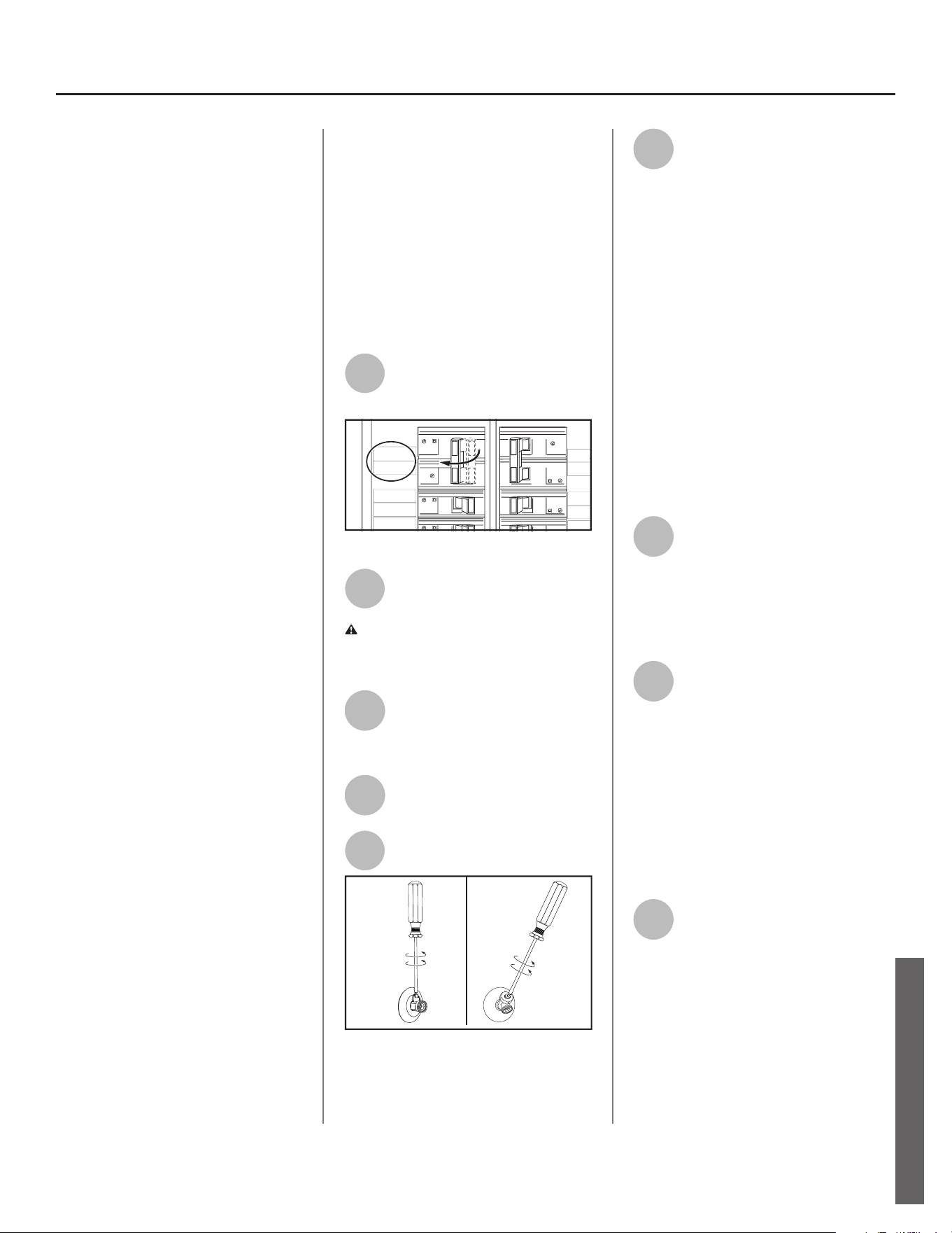
Residen al Electronic Thermostat Electric Water Heater Use and Care Guide • 25
MAINTENANCE
MAINTENANCE
Rou ne Maintenance
Rou ne maintenance will help your
water heater last longer and work more
effi ciently. If you can’t perform these
rou ne maintenance tasks yourself,
contact a qualifi ed person.
Water Heater Maintenance
A er the fi rst six months, drain and
fl ush the water heater and inspect the
anode rod. Depending on the hard-
ness of your water, repeat this process
at least annually, or more frequently if
needed. From me to me you may
need to replace a hea ng element or
the electronic thermostat. All three
maintenance tasks are described below.
Draining and Flushing the
Water Heater
Tap water contains minerals that can
form lime deposits on hea ng elements
or sediment in the bo om of the tank.
The amount of lime deposits or sedi-
ment depends on the hardness of your
tap water. The rate at which sediment
builds up depends on water quality and
hardness in your area, the tempera-
ture se ngs, and other variables. We
recommend draining and fl ushing the
water heater a er the fi rst six months
of opera on to determine the amount
of sediment build up. Draining sedi-
ment extends the life of the tank, heat-
ing elements, and drain valves.
• In areas with very hard water, remove
and check the hea ng elements
whenever you drain the tank. If you
have heavy lime deposits on hea ng
elements, you will need to replace
them more o en.
• Sediment may form large masses that
can prevent the tank from draining.
Have a qualifi ed person use a de-liming
agent suitable for potable water to
remove the sediment buildup.
• In most cases, it is easier and cheaper
to replace lime-encrusted elements
than trying to remove heavy lime
deposits.
To drain and fl ush the tank:
1
Locate the water heater’s
circuit breaker and turn it OFF
(or remove the circuit’s fuses).
WATER
HEATER
MICRO-
WAVE
LIVING
50
50
1
RANG
E
STOV
E
2
20
20
5
DISH
WAS
HE
HALL
TYPE HOM
SERIES 1
10 kA
120/240 V-
TYPE HOM
SERIES 1
10 kA
120/240 V-
T
S
1
1
TYPE HOM
SERIES 1
10 kA
120/240 V-
TYPE HOM
SERIES 1
10 kA
120/240 V-
H
OM
S
1
4
0 V-
30
30
30
30
Figure 28 - Circuit Breaker
2
Open a hot water faucet and
let the hot water run un l it is
cool.
WARNING! Be sure the water runs
cool before draining the tank to reduce
the risk of scalding.
3
Connect a garden hose to the
drain valve and place the other
end of the hose in a drain,
outside, or in buckets.
4
Turn the cold water supply
valve OFF.
5
Open the drain valve on the
water heater.
Figure 29 - Open Drain Valve
4
Open a hot water faucet to
help the water in the tank
drain faster.
NOTICE: DO NOT reconnect power
to water heater unless the tank is
completely full of water. This is an
addi onal precau on to protect the
elements against dry fi re. Dry fi re
occurs when power is supplied to the
electric elements without suffi cient
water in the heater. Dry fi ring the
unit will result in immediate failure
of the element. While this unit is
equipped with dry fi re protec on, the
recommended prac ce is to ensure
the tank is fi lled with water prior
to supplying power to the unit. For
complete instruc ons on fi lling the
tank, follow “Step 13” on page 16 in
the installa on sec on of this manual.
5
If sediment was present when
the tank was drained, fl ush
the tank by opening the cold
water supply valve and le ng the
water run un l no more sediment
drains from the tank. Close the drain
valve when you are done.
6
Refi ll the tank by opening the
cold water supply valve. Make
sure a hot water faucet is
open and the drain valve is closed.
Allow the hot water to run full for at
least three minutes to make sure the
tank has all the air removed and is
completely full of water. Failure to
perform this step can cause the upper
hea ng element to burn out. Once you
are certain the tank is completely full
of water, close the hot water faucet.
7
Turn ON power to the water
heater at the circuit breaker/
fuse box. It may take two
hours for the tank to heat up.
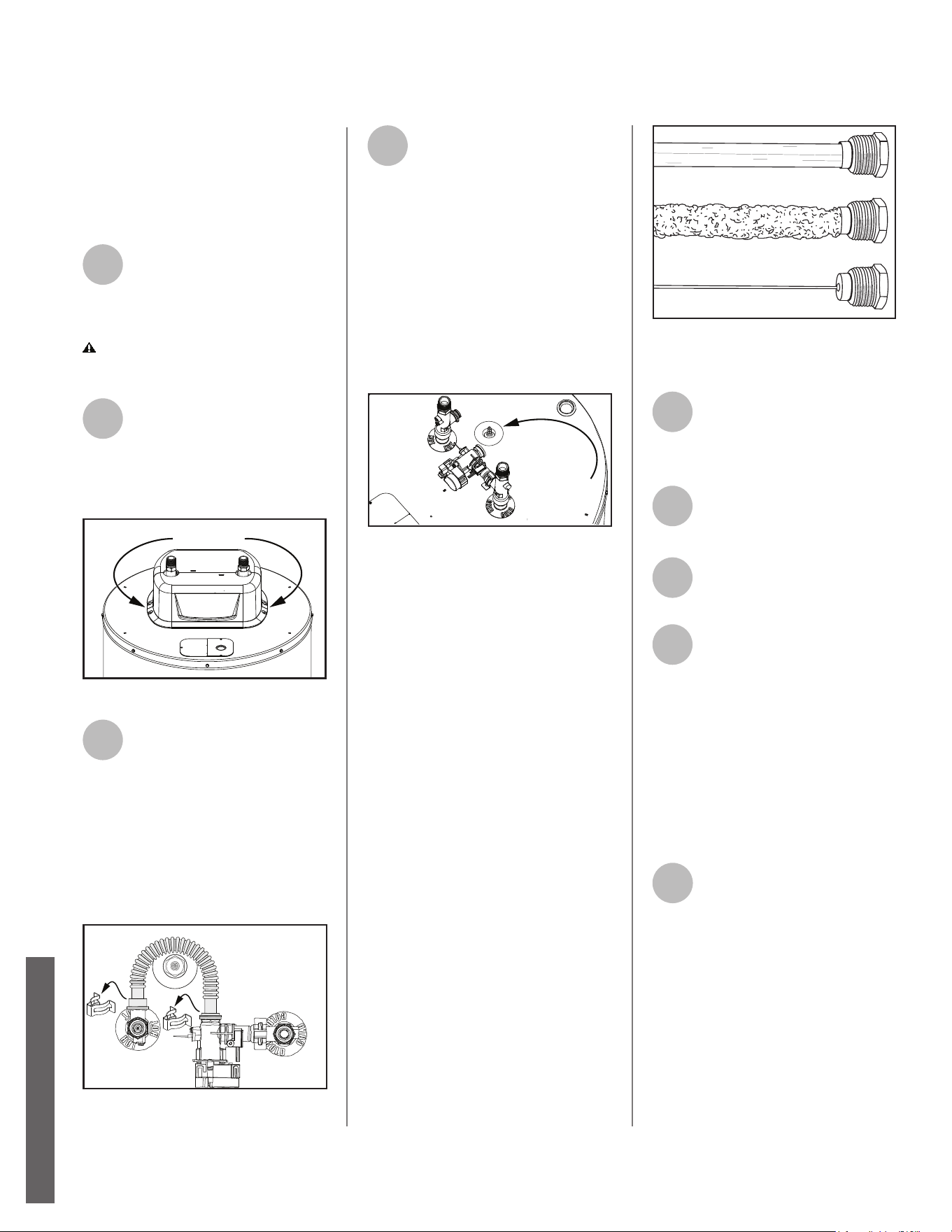
Replacing the Anode
Rod
NOTICE: The Control Assembly will
display error code 044 when the
anode rod has been depleted.
1
To replace the anode rod if it
is depleted: Follow the
instruc on on page 25,
Draining and Flushing The Water
Heater.
C AUTION! Residual water pressure
may s ll be present in the water lines
and tank.
2
Using a 1/4” nut driver, locate
and remove the four (4)
screws securing the shroud
cover to the top of the heater. Lift the
shroud cover up and away from the
top of the heater. See Figure 30.
Shroud
Fastener Screws
Figure 30 - Shroud fastener screw locations.
3
With the shroud removed,
gently remove the spring clips
(2) securing the fl ex hose to
the smart valve hot t-nipple. Place
components safely to the side.
NOTICE: DO NOT bend the fl ex hose.
Take note of the orienta on in which
the fl ex hose is installed to the smart
valve. The fl ex hose will need to
be reintalled correctly in order to
func on properly. See Figure 31.
Figure 31 - Flex hose spring clips removal.
4
Once the anode rod is
exposed, remove the top nut
with a 10 mm hex socket
wrench and remove the wire terminal
(do not remove lower hex nut from
bolt). With the wire terminal
removed, use a 1-1/16” deep socket
wrench with an extension to remove
the anode rod. Inspect the anode rod
and replace if depleted. Apply thread
sealant tape or pipe joint compound
and reinstall the anode rod ghtly.
Connect the wire terminal and secure
with hex nut. See Figure 32.
Anode
Location
(Remove Cover)
Figure 32 - Anode location.
Anode Rod. The anode rod is a
sacrifi cial metal rod and is the water
heater’s fi rst line of defense to
prevent corrosion and premature
failure (leaks) in the tank. The anode
rod is a consumable item. Inspect the
anode rod a er the fi rst six months of
opera on when you drain and fl ush
the tank. Replace the anode rod if it
is substan ally worn out or depleted.
Therea er, inspect the anode rod
annually or more frequently if
needed. If you use a water so ener,
your anode rod will deplete faster
than normal. Inspect the anode
rod more frequently, replacing
the anode rod as needed. Obtain
new anode rods from your local
plumbing supplier or have a qualifi ed
person replace it (anode rods are a
consumable item and are not covered
under warranty). See Figure 33.
Figure 33 - Anode Rods from new (top) to
partially depleted (middle) to fully depleted
(bottom).
5
Reinstall the fl ex hose to the
smart valve and hot t-nipple,
in the correct orienta on.
Secure the fl ex hose with the (2)
spring clips. Refer to step 3.
6
Reinstall the shroud by
securing it in place with the
(4) screws. Refer to step 2.
7
Reconnect cold water supply
and hot water supply
connec ons at top of unit.
8
Refi ll the tank by opening the
cold water supply valve.
Make sure a hot water faucet
is open and the drain valve is closed.
Allow the hot water to run full for at
least three (3) minutes to make sure
the tank has all the air removed and is
completely full of water. Failure to
perform this step can cause the upper
hea ng element to burn out. Once
you are certain the tank is completely
full of water, close the hot water
faucet.
10
Restore power to the water
heater. It may take two hours
for the tank to heat up.
MAINTENANCE
MAINTENANCE
26 • Residen al Electronic Thermostat Electric Water Heater Use and Care Guide
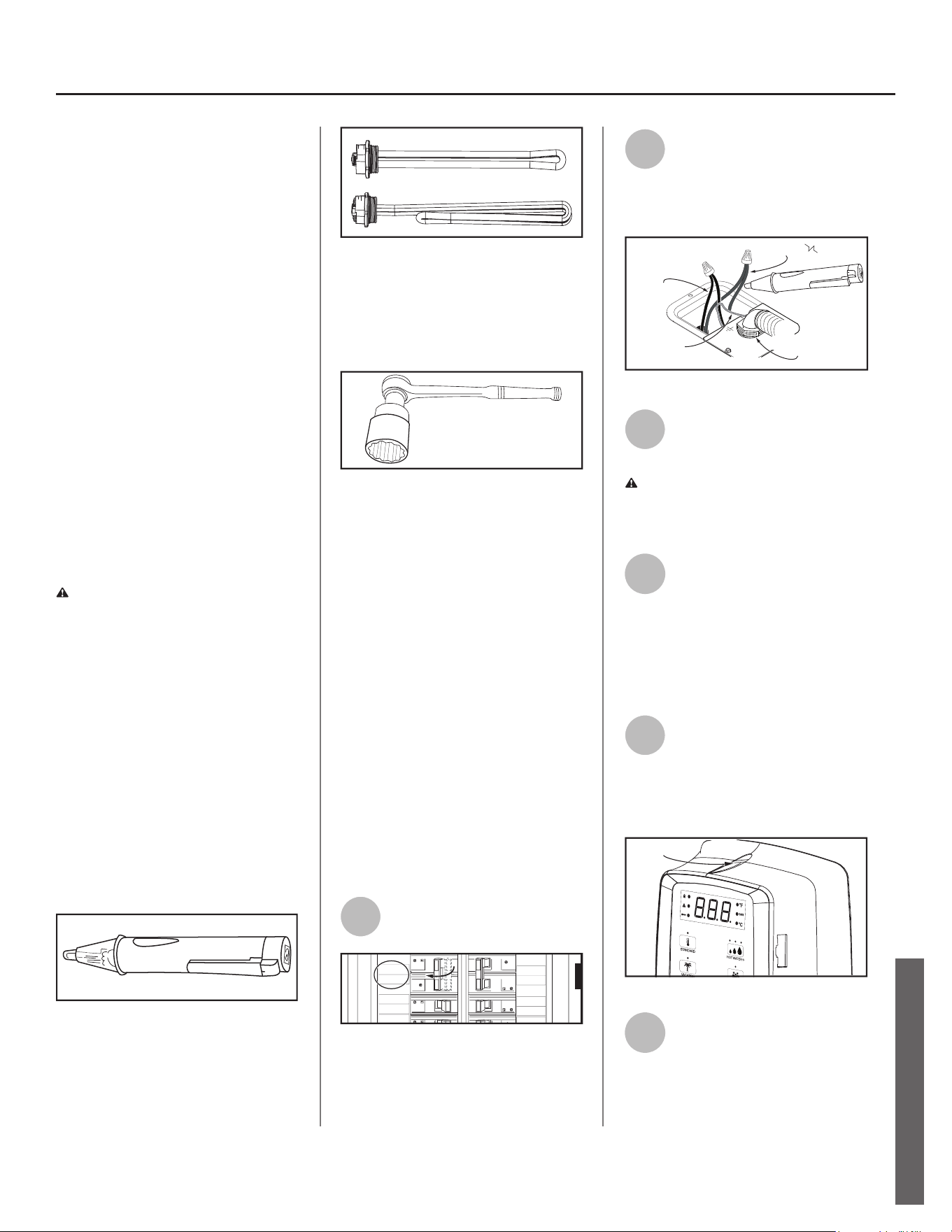
Residen al Electronic Thermostat Electric Water Heater Use and Care Guide • 27
MAINTENANCE
Cleaning the Hea ng
Element
At least annually, inspect upper and
lower elements for scaling or damage
caused by corrosive water condi ons
and mineral deposits.
Use a so bristle brush to remove
scale from the elements. If necessary,
soak the elements in cider vinegar for
two hours to remove scale.
Follow the instruc ons in the next
sec on to disconnect power to the
water heater and drain the tank
before accessing the elements.
IMPORTANT! Failure to clean scaling
from elements can lead to corrosion
and premature failure (leaks) in the
tank resul ng in property damage.
Replace the hea ng elements if
necessary.
Replacing the Hea ng
Element
WARNING! Working on an
energized circuit can result in severe
injury or death from electrical shock.
Turn power off . Check wires with a
non-contact circuit tester to make
sure power is off . When you are
fi nished, be sure all covers are secured
to reduce the risk of fi re and electric
shock.
If you are not comfortable replacing a
hea ng element or thermostat your-
self, have this work done by a qualifi ed
person. To replace the hea ng ele-
ment, you’ll need the following tools
and supplies:
ON
OFF
Figure 34 - Non-Contact Circuit Tester
• Always turn power OFF and check
the power wires with a non-contact
circuit tester before working on the
water heater.
Figure 35 - Heating Element (with gasket)
• Check your water heater’s data plate
for the correct wa age and voltage.
Hea ng elements are available at
your local plumbing supplier.
Figure 36 - Element Wrench
• Some regular sockets (1 1/2 inch)
may work, but regular sockets are
o en beveled and may slip. Inexpen-
sive element wrenches are available
at your local plumbing supplier.
• Garden hose to drain the tank
• Hand dishwashing soap to lubricate
the gasket
• A clean cloth to clean the threaded
opening
• A fl at blade and a Phillips screwdriver
Steps for Replacing the Hea ng
Element:
NOTICE: A diagnos c code (page.20)
should indicate if the upper or lower
element has failed.
1
Turn the power OFF at the
circuit breaker or remove fuses.
WATER
HEATER
MICRO-
WAVE
LIVING
50
50
1
RANGE
STOVE
2
20
20
5
DISH
WASHER
HALL
TYPE HOM
SERIES 1
10 kA
120/240 V-
TYPE HOM
SERIES 1
10 kA
120/240 V-
T
S
1
1
TYPE HOM
SERIES 1
10 kA
120/240 V-
TYPE HOM
SERIES 1
10 kA
120/240 V-
H
OM
S
1
4
0 V-
30
30
30
30
Figure 37 - Circuit Breaker
2
Open the electrical junc on
box on top of the water
heater. Using a non-contact
circuit tester, check the power wires to
make certain the power is OFF.
Red Wires
Ground
Wires
Black Wires
Connection
1/2” Conduit
ON
OFF
Figure 38 - Non-Contact Circuit Tester
3
Open a hot water faucet and
let the hot water run un l it is
cool.
WARNING! Be sure the water runs
cool before draining the tank to
reduce the risk of scalding.
4
Connect a garden hose to the
drain valve and place the other
end of the hose in a drain or
outside (or use buckets). Turn OFF the
cold water valve that supplies the water
heater. Open the drain valve on the
water heater. Opening a hot water
faucet will help the tank drain faster.
5
Remove the upper control
assembly or lower access
panel on the water heater,
and then fold back the insula on and
remove the plas c element/thermo-
stat cover.
Screw Location
Figure 39 - Control Assembly
6
With the tank drained and
power off , remove the power
wires from the element you
intend to replace.
MAINTENANCE
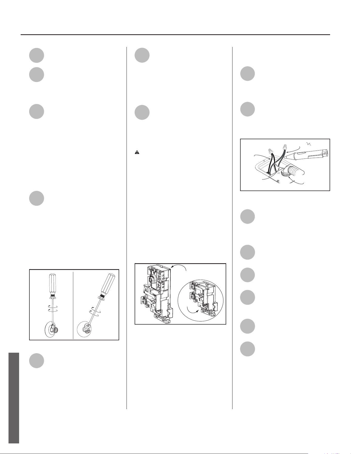
28 • Residen al Electronic Thermostat Electric Water Heater Use and Care Guide
7
Remove the bad element
using an element wrench.
8
Make sure the new element is
the correct replacement by
referring to the water heater’s
data plate for voltage and wa age
informa on.
9
Clean the threads in the tank
opening with a rag. Insert the
new element equipped with a
rubber gasket. NOTE: Use a drop of
hand dishwashing liquid to lubricate
the gasket to help avoid damaging the
gasket as it is being ghtened. Tighten
with an element wrench.
NOTICE: Do not turn power back on
un l the tank is completely full of water.
For complete instruc ons on fi lling the
tank, follow Step 8 in the Installa on
sec on.
10
Refi ll the tank by opening the
cold water supply valve. Make
sure a hot water faucet is
open and the drain valve is closed.
Allow the hot water to run full for at
least three minutes to make sure the
tank has all the air removed and is
completely full of water. Failure to
perform this step can ac vate the
Dry-Fire diagnos c code. Once you are
certain the tank is completely full of
water, close the hot water faucet.
Figure 40 - Closing Drain Valve
11
Check the newly installed
element for leaks. If a leak is
present, ghten the element
un l the leak stops. If you cannot stop
the leak, drain the tank and remove the
element. Inspect the gasket for
damage. If the gasket is damaged,
replace the gasket and re-install the
element.
12
Once the element is success-
fully installed and there are no
leaks, replace the power
wires, thermostat cover, insula on, and
control assembly or access panel.
Make sure all wire connec ons are
ght. Replace the cover on the
electrical junc on box.
13
Restore power to the water
heater. It may take two hours
for the tank to heat up.
Replacing the Electronic
Thermostat
WARNING! Working on an ener-
gized circuit can result in severe injury
or death from electrical shock. Turn
power off . Check wires with a non-
contact circuit tester to make sure
power is off . When you are fi nished,
be sure all covers are secured to
reduce the risk of fi re and electric
shock.
To replace the thermostat, you’ll need
the following tools and supplies:
• A non-contact circuit tester. Always
turn power OFF and check with a non-
contact circuit tester before working on
the water heater.
Lower
Thermostat
Upper
Thermostat
Figure 41 - Upper and Lower Thermostats
• Replacement thermostats are avail-
able and may be ordered from the
Repair Parts List on page 33 of this
manual.
• A business card to check the gap be-
tween the thermostat and the tank
• Tape and a permanent marker to
mark the wires
• A fl at blade and a Phillips screwdriver
Steps for Replacing the
Thermostat:
1
Turn the power OFF at the
circuit breaker or remove fuses.
NOTICE: It is not necessary to drain the
tank to replace a thermostat.
2
Open the electrical junc on box
on top of the water heater. Using
a non-contact circuit tester,
check the power wires to make certain the
power is OFF.
Red Wires
Ground
Wires
Black Wires
Connection
1/2” Conduit
ON
OFF
Figure 42 - Non-Contact Circuit Tester
3
Remove the upper control
assembly or lower access
panel on the water heater and
carefully fold back the insula on and
plas c element/thermostat cover.
4
The replacement electronic
thermostat should match the
original electronic thermostat.
5
Mark the wires with tape so
you’ll know how to put them
back on.
6
Disconnect the wires from the
bad electronic thermostat and
remove the electronic ther-
mostat from the metal moun ng clip.
7
Install the new electronic
thermostat in the metal
moun ng clip.
8
Make sure the new thermo-
stat fi ts snugly against the
tank. You should NOT be able
to slip a business card between the
ECO and tank. If needed, you can bend
the thermostat moun ng clip un l the
electronic thermostat fi ts ghtly against
the tank.
MAINTENANCE
MAINTENANCE
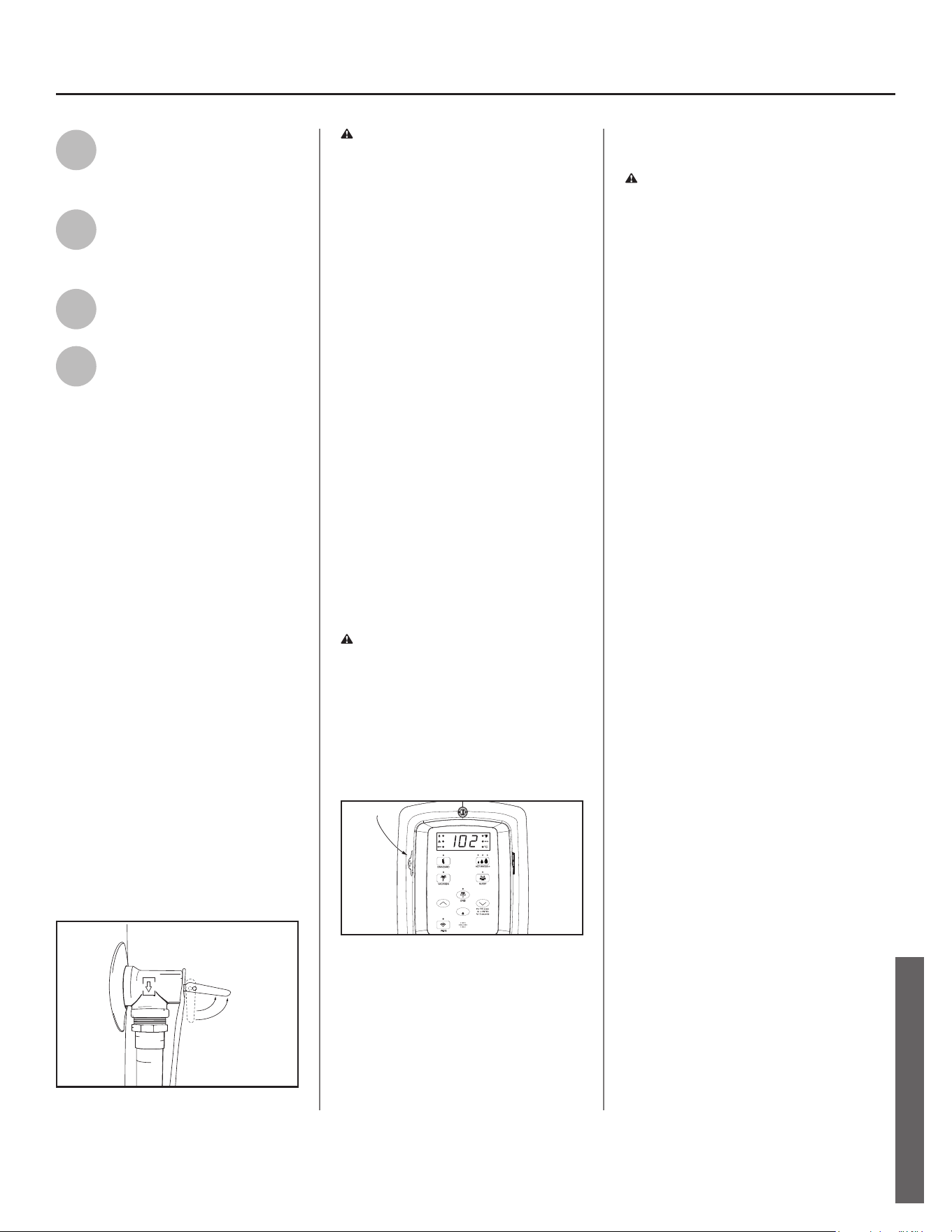
Residen al Electronic Thermostat Electric Water Heater Use and Care Guide • 29
MAINTENANCE
9
A ach the wires following the
wiring diagram on the water
heater’s label. Make sure all
wire connec ons are ght.
10
Replace the plas c element/
thermostat cover, insula on,
and upper control assembly or
lower access panel.
11
Replace the cover on the
electrical junc on box.
12
Restore power to the water
heater. It may take two hours
for the tank to heat up.
T&P Relief Valve Maintenance
Read and follow the opera ng and
annual maintenance instruc ons
provided by the manufacturer of the
T&P Relief Valve (yellow label a ached
to T&P Relief Valve). If no label is at-
tached to the T&P Relief Valve, follow
the instruc ons in this sec on. Miner-
als in the water can form deposits
that cause the valve to s ck or create
blocked passages, making the T&P
Relief Valve inopera ve. Follow these
guidelines:
• At least annually, operate the T&P
Relief Valve manually to ensure the
waterways are clear and the valve
mechanism moves freely (above).
Before opera ng the valve manually,
check that it will discharge in a place
for secure disposal. If water does
not fl ow freely from the end of the
discharge pipe, turn OFF the power
to the water heater. Call a qualifi ed
person to determine the cause.
Figure 43 - T&P Relief Valve
WARNING! Hot water will be
released. Before opera ng the T&P
relief valve manually, check that it will
discharge in a safe place. If water does
not fl ow freely from the end of the
discharge pipe, turn the power to the
water heater OFF. Call a qualifi ed
person to determine the cause.
• At least every fi ve years, have a quali-
fi ed person inspect the T&P Relief
Valve and discharge pipe. Damage
caused by corrosive water condi ons,
mineral deposits, or other problems
can only be determined when a qual-
ifi ed person removes and inspects
the valve and its components.
• Note that a dripping T&P Relief Valve
is usually caused by the home’s water
pressure being too high or the lack
of a Thermal Expansion Tank. If your
T&P Relief Valve drips, see page 25.
Control Assembly Ba ery
Maintenance
CAUTION! Ba ery May Explode If
Mistreated. Do Not Recharge,
Disassemble Or Dispose Of In Fire.
It is recommended to replace the bat-
tery in the control assembly every 5
years for reliability.
Locate the ba ery tray on the le side
of the control assembly. See Figure 41.
°C
DAYS
ENTER
Battery
Location
Figure 44 - Battery Tray Location
Replace the BR2032 or CR2032 ba ery
by removing the Phillips heads screw
and sliding the ba ery tray out from
the control assembly. Replace ba ery
with Panasonic® BR2032 or Murata
CR2032 only. Insert ba ery into the
tray and reinstall into the control
assembly. Hand ghten the Phillips
head screw to secure the tray in the
control assembly.
CAUTION! Use of Another Ba ery
May Present A Risk of Fire or
Explosion.
NOTICE: If the control assembly was
not connected via WiFi or powered
by a power source, the time will
need to be set.Smart Valve Assem-
bly
NOTICE: The Control Assembly will
display error code 047 when the
Smart Valve experiences a failure. To
replace the Smart Valve, follow the
instruc ons below.
MAINTENANCE
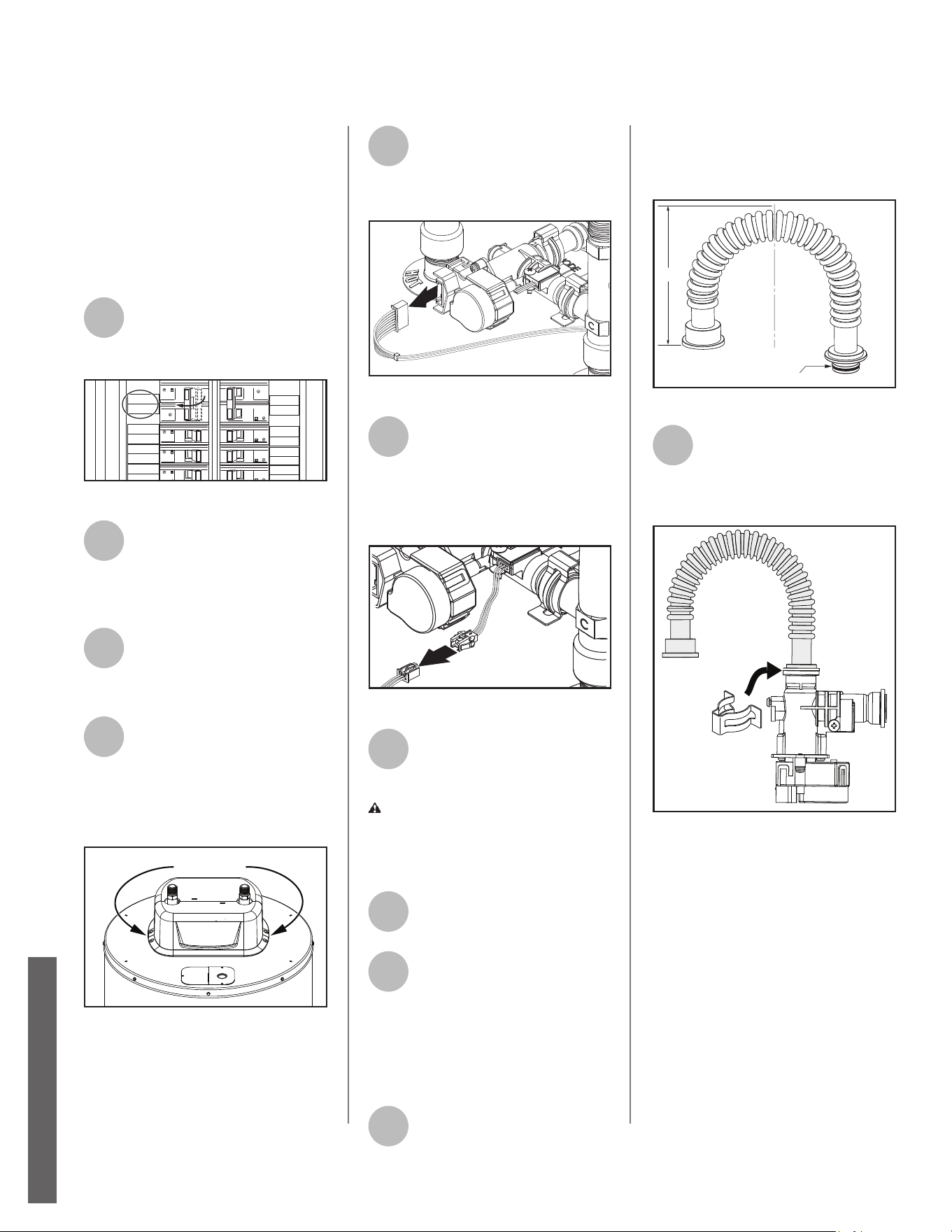
Smart Valve Assembly
NOTICE: The Control Assembly will
display error code 047 when the
Smart Valve experiences a failure. To
replace the Smart Valve, follow the
instruc ons below.
Remove Smart Valve Assembly
1
Locate the water heater’s
circuit breaker and turn it
OFF (or remove the circuit’s
fuses).
WATER
HEATER
MICRO-
WAVE
LIVING
ROOM
50
50
1
RANGE
STOVE
2
20 20
15
2015
20
FRIDGE
PLUG
DISH
WASHER
HALL
LIGHTS
LAUNDRY
ROOM
TYPE HOM
SERIES 1
10 kA
120/240 V-
TYPE HOM
SERIES 1
10 kA
120/240 V-
TYPE HOM
SERIES 1
10 kA
120/240 V-
TYPE HO
M
SERIES 1
10 kA
120/240
V
TYPE HOM
SERIES 1
10 kA
120/240 V-
TYPE HOM
SERIES 1
10 kA
120/240 V-
TYPE HOM
SERIES 1
10 kA
120/240 V-
TYPE HOM
SERIES 1
10 kA
120/240 V-
30
30
30
30
Figure 45 - Circuit Breaker.
2
Open the electrical junc on
box on the side of the water
heater. Using a non-contact
circuit tester, check the power wires
to make certain the power is OFF.
3
Turn the cold water supply
valve OFF. Open a hot water
faucet to remove pressure
from the tank.
4
Using a 1/4” nut driver, locate
and remove the four (4)
screws securing the shroud
cover to the top of the heater. Lift the
shroud cover up and away from the
top of the heater to gain access. See
Figure 46.
Shroud
Fastener Screws
Figure 46 - Shroud fastener screw locations.
5
Disconnect the 8 pin wire
harness located on top of
Smart Valve as shown in
Figure 47. Place wires aside in a safe
loca on so they are not damaged.
Figure 47 - Disconnect 8 Pin Wire Harness
6
Disconnect the 3 pin wire
harness. Connector will be
located near the cold water
supply opposite from Smart Valve as
shown in Figure 48. Place wires aside
in a safe loca on so they are not
damaged.
Figure 48 - Disconnect 3 Pin Wire Connector
7
Remove the two (2) spring
clips securing Smart Valve to
cold t-nipple and fl ex hose to
hot t-nipple.
CAUTION! Water may s ll be
present in the valve and fl ex hose
assembly. Place a rag under the fl ex
hose and valve connec on points to
soak up any water.
8
Gently remove Smart Valve
and fl ex hose from hot and
cold t-nipples.
9
Properly dispose of Smart
Valve, fl ex hose and spring
clips.
Replace Smart Valve Assembly
NOTICE: DO NOT reuse old spring
clips and O-rings. Use new spring clips
and O-rings provided in kit.
10
Remove new fl ex hose from
service kit. Carefully bend fl ex hose to
allow for easy connec on to Smart
Valve and hot t-nipple as shown in
Figure 49.
Top View
180°
O-ring
Figure 49 - Bend Flex Hose
11
Remove new Smart Valve
from service kit. Install male
end of fl ex hose with small
O-ring (14.5mm) to Smart Valve outlet
as shown in Figure 50.
Figure 50 - Install Flex Hose to Smart Valve
NOTICE: Inspect fl ex hose O-ring for
damage or debris. Handle with care
and verify lubricant has been applied
to O-ring.
30 • Residen al Electronic Thermostat Electric Water Heater Use and Care Guide
MAINTENANCE
MAINTENANCE
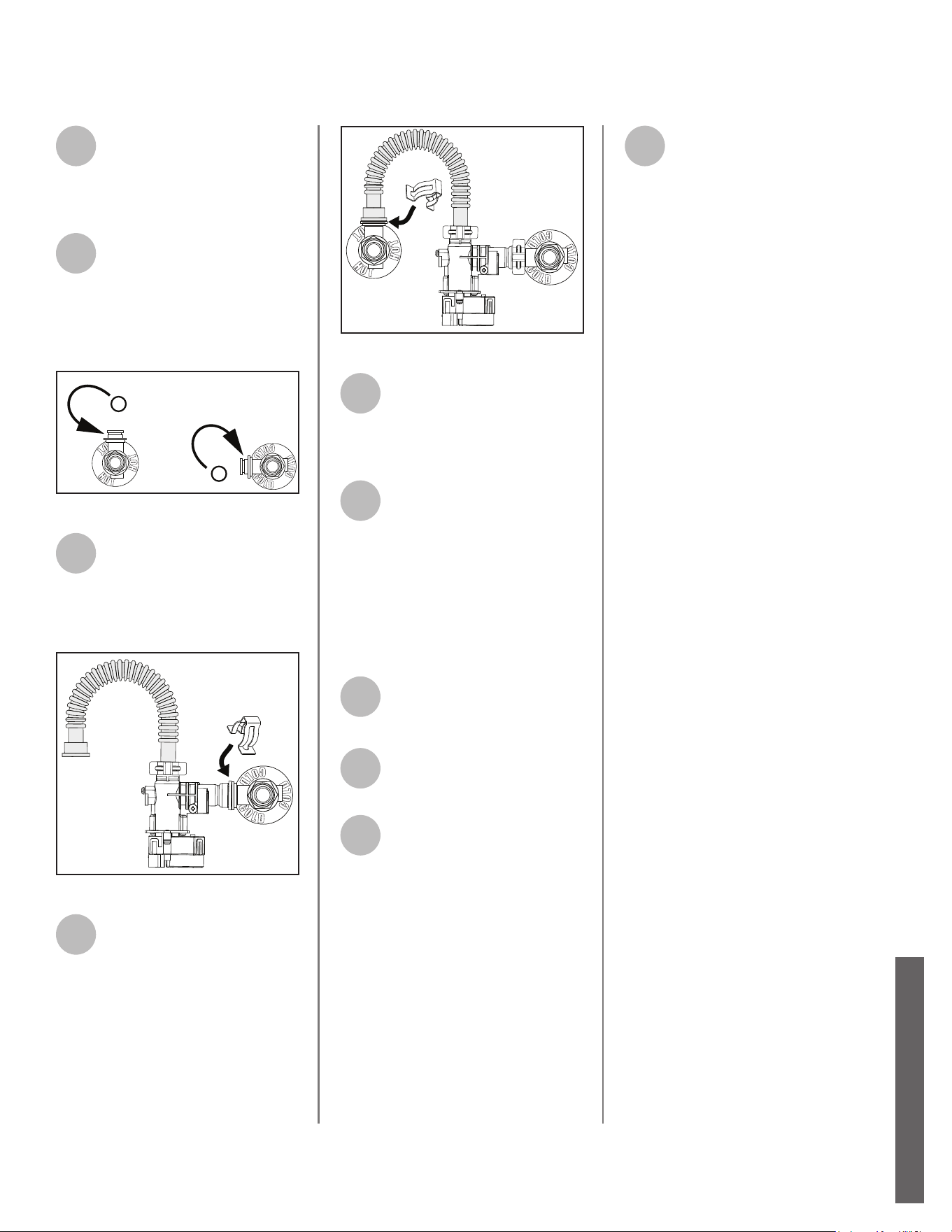
12
Remove one (1) spring clip
from kit. Install spring clip
over Smart Valve outlet and
fl ex hose to secure the assembly as
shown in Figure 50.
13
Remove O-rings installed to
hot and cold t-nipples and
replace with larger o-rings
(15.5mm) provided in kit. See Figure
51.
NOTICE: Handle with care and verify
lubricant has been applied to o-ring.
Install New
O-rings
Figure 51 - Install Flex Hose to Smart Valve
14
Carefully install Smart Valve
inlet to cold t-nipple. Remove
one (1) spring clip from kit.
Install spring clip over Smart Valve
inlet and cold t-nipple to secure Smart
Valve. See Figure 52.
Figure 52 - Install Smart Valve to Cold T-nipple
15
Carefully install female end of
fl ex hose to hot t-nipple.
Remove fi nal spring clip from
kit. Install spring clip over fl ex hose
and hot t-nipple to secure fl ex hose.
Figure 53 - Install Flex Hose to Hot T-nipple
16
Locate the 3 pin wire harness
connector previously set
aside in Step 3 and connect it
to the 3 pin wire harness connector
on new Smart Valve assembly.
17
Locate the 8 pin wire harness
previously set aside in Step 2
and connect to Smart Valve
assembly.
NOTICE: Confi rm all wire connec ons
are ght and oriented such that
they will not interfere with other
components in the heat pump
compartment.
18
Reinstall the shroud by
securing it in place with the
(4) screws. Refer to step 2.
19
Reconnect cold water supply
and hot water supply
connec ons at top of unit.
20
Refi ll the tank by opening the
cold water supply valve.
Make sure a hot water faucet
is open and the drain valve is closed.
Allow the hot water to run full for at
least three (3) minutes to make sure
the tank has all the air removed and is
completely full of water. Failure to
perform this step can cause the upper
hea ng element to burn out. Once
you are certain the tank is completely
full of water, close the hot water
faucet.
21
Restore power to the water
heater. It may take two hours
for the tank to heat up.
Residen al Electronic Thermostat Electric Water Heater Use and Care Guide • 31
MAINTENANCE
MAINTENANCE
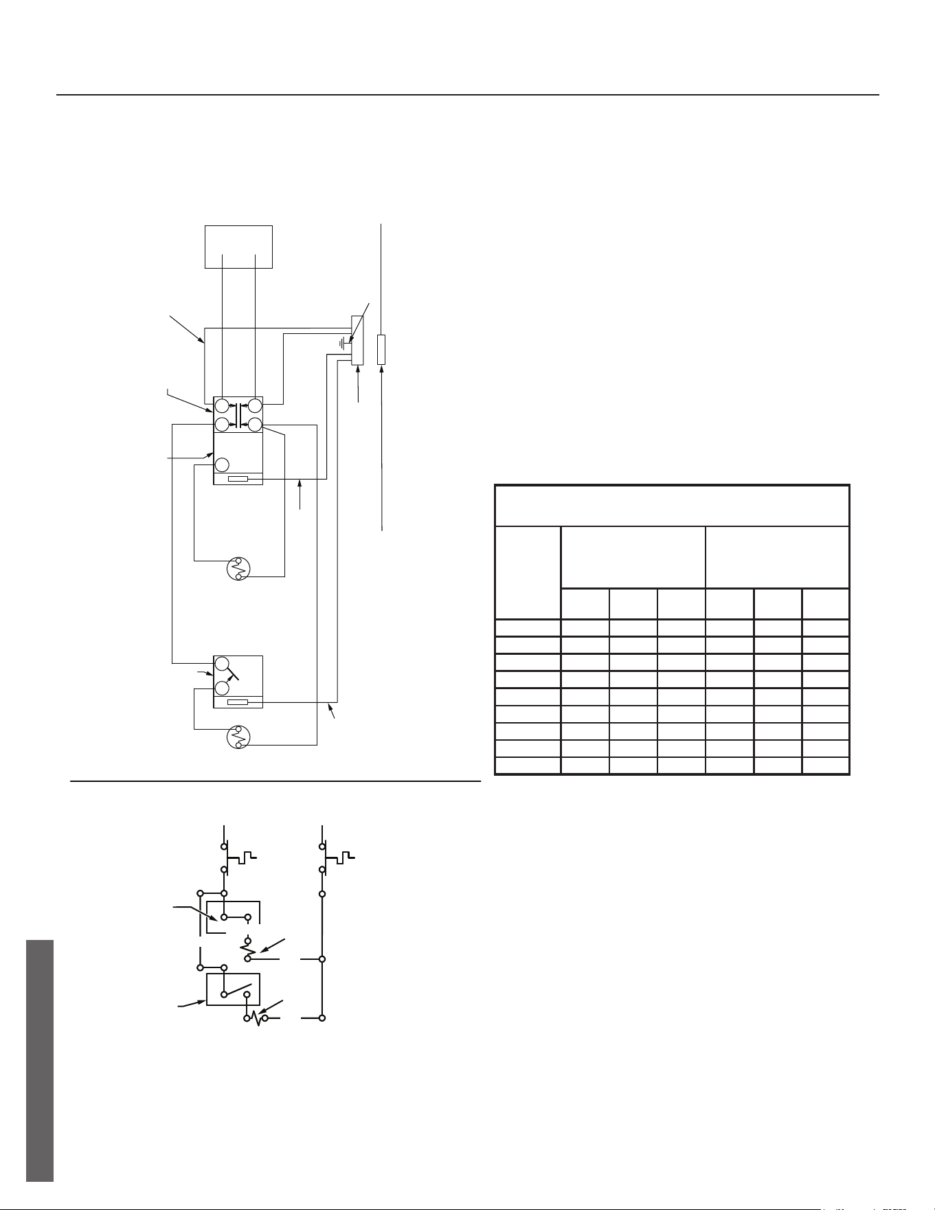
DIAGRAMS
Thermostat Wiring Diagram
1
2
1
3
4
2
1
LOWER
THERMOSTAT
ELECTRONIC
CONTROL
HARNESS
GROUND
LOW VOLTAGE
RE3 HARNESS
(100337697)
SLEEVED
(5) WIRES
BLACK
BLACK
RED
BLACK
BLACK
RED
BLUE
YELLOW
LOWER
HEATING ELEMENT
UPPER
HEATING ELEMENT
HI-TEMP
LIMIT
SWITCH
UPPER
THERMOSTAT
JUNCTION BOX
SLEEVED
(1) WIRE (SAC)
(2) WIRES (TC)
(3) WIRES (FS)
(8) WIRES (SV)
LOW VOLTAGE
ELECTRONICS
HARNESS
SLEEVED
(5) WIRES
(2) WIRES (LDM)
(1) WIRE (ZC)
UPPER
THERMOSTAT
UPPER
ELEMENT
LOWER
THERMOSTAT
LOWER
ELEMENT
120
V
1500*
2000
2500
3000
3500
4000
4500
5000
5500
15
20
30
30
-
-
-
-
-
WATT
LOAD
BRANCH CIRCUIT SIZING GUIDE
Based on N.E.C. NFPA NO. 70 - 1999
15
15
15
20
20
25
30
30
15
15
15
15
20
20
25
30
30
208
V
240
V
Recommend
Over Current
Protection Rating
12
10
10
8
-
-
-
-
-
14
14
14
12
10
10
10
10
14
14
14
12
12
10
10
10
10
120
V
208
V
240
V
Copper Wire Size
AWG Based on
N.E.C.
Table 310 - 16 C)
Wattages less than 1500 may be wired 14 gage with a maximum
15 amp protection.
REDBLACK
HI-TEMP
LIMIT
SWITCH
BLACK
RED
RED
YELLOW
32 • Residen al Electronic Thermostat Electric Water Heater Use and Care Guide
DIAGRAMS
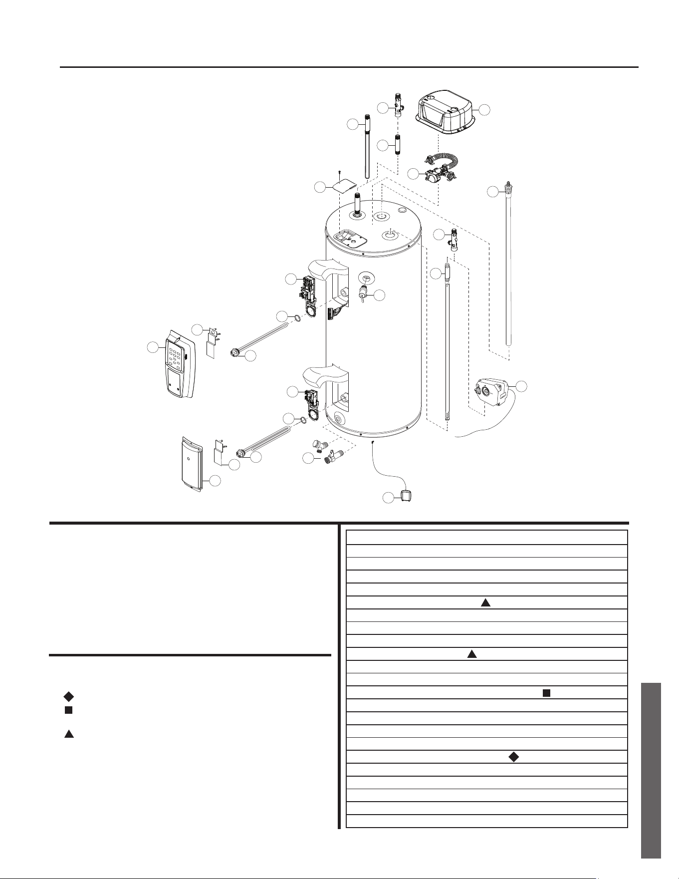
Repair Part Illustra on
REPAIR PARTS
REPAIR PARTS
Qu
ick
R
elease
to re
move valve body
16
15
18
14
19
13
22
21
5
4
3
2
1
12
9
4
8
7
6
10
11
17
20
ITEM No. PARTS DESCRIPTION
1 CONTROL ASSEMBLY
2 UPPER THERMOSTAT COVER
3 UPPER ELEMENT
4 ELEMENT GASKET
5 UPPER THERMOSTAT/ECO
6 ACCESS DOOR
7 LOWER THERMOSTAT COVER
8 LOWER ELEMENT
9 LOWER THERMOSTAT
10 DRAIN VALVE
11 LEAK DETECTOR SENSOR (LDS)
12 TEMPERATURE AND PRESSURE RELIEF VALVE
13 JUNCTION BOX COVER
14 HEAT TRAP/OUTLET COMBINATION
15 NIPPLE W/HEAT TRAP
16 DIP TUBE (INCLUDES NIPPLE AND HEAT TRAP)
17 ANODE ROD, 37” FOR ALL MODELS
18 (OPTIONAL) AUTOMATIC COLD WATER SHUT-OFF VALVE
19 OUTLET T-NIPPLE
20 INLET T-NIPPLE
21 SMART VALVE
22 SHROUD
Repair Parts
Repair parts may be ordered through your plumber,
local distributor, home improvement center, or by calling
1-800-821-2017. When ordering repair parts, always
give the following information:
1. Model, serial and product number
2. Item number
3. Parts description
Repair Parts List
Legend
Special anode rod (See “Anode Rod/Water Odor” section)
Temperature and Pressure Relief Valve is required, but may not
be factory installed.
Specify element type when ordering

Apple logo and Apple App Store Logo are trademarks of Apple Inc.
Google Play and the Google Play Logo are trademarks of Google LLC.
Copyright © 2021, A. O. Smith
All Rights Reserved.