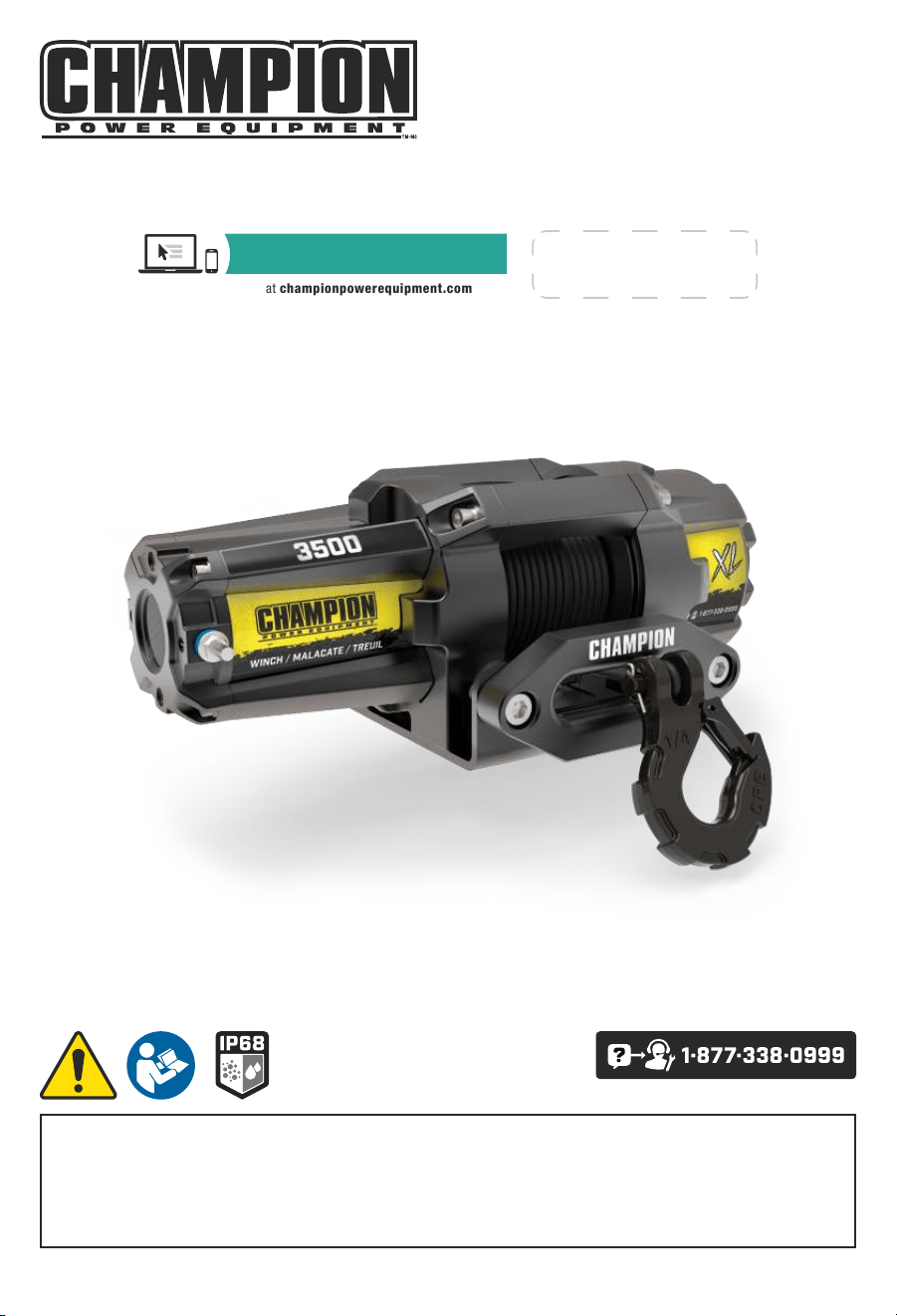
OPERATOR'S MANUAL
MODEL #100722
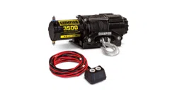
3500 LB. (1588 KG) WINCH
REV 20201222 Champion Power Equipment, Inc., Santa Fe Springs, CA USA
or visit championpowerequipment.com
SAVE THESE INSTRUCTIONS. This manual contains important safety precautions which should be read and
understood before operating the product. Failure to do so could result in serious injury. This manual should remain
with the product.
Specifications, descriptions and illustrations in this manual are as accurate as known at the time of publication,
but are subject to change without notice.
REGISTER YOUR PRODUCT ONLINE
at championpowerequipment.com

100722 - 3500 LB. (1588 KG) WINCH
TABLE OF CONTENTS
2
TABLE OF CONTENTS
Introduction ................................. 3
Safety Definitions
......................... 3
Important Safety Instructions
......... 4
Operation Symbols ............................... 5
Controls and Features ................... 6
Winch .......................................... 6
Parts Included ................................... 8
Assembly .................................... 9
Mounting the Winch .............................. 9
Solenoid/Contactor Location ...................... 9
Install the Rocker Switch ........................ 10
Wiring the Winch ................................ 10
Wiring Diagram ................................. 12
Switch Wiring Diagram .......................... 12
Operation .................................. 13
General Tips for Safe Operation ................... 13
Self Recovery .................................. 13
Synthetic Rope Abrasion Sleeve .................. 14
Winching Techniques A-Z ........................ 14
Maintenance .............................. 15
Lubrication ..................................... 15
Synthetic Rope Replacement ..................... 15
Synthetic Rope ................................. 15
Specifications ............................ 16
Performance Specifications ...................... 16
Troubleshooting .......................... 17

100722 - 3500 LB. (1588 KG) WINCH
INTRODUCTION
3
INTRODUCTION
Congratulations on your purchase of a Champion Power
Equipment (CPE) product. CPE designs, builds, and
supports all of our products to strict specifications and
guidelines. With proper product knowledge, safe use, and
regular maintenance, this product should bring years of
satisfying service.
Every effort has been made to ensure the accuracy and
completeness of the information in this manual at the time
of publication, and we reserve the right to change, alter
and/or improve the product and this document at any time
without prior notice.
CPE highly values how our products are designed,
manufactured, operated, and serviced as well as
providing safety to the operator and those around the
winch. Therefore, it is IMPORTANT to review this product
manual and other product materials thoroughly and
be fully aware and knowledgeable of the assembly,
operation, dangers and maintenance of the product before
use. Fully familiarize yourself, and make sure others who
plan on operating the product fully familiarize themselves
too, with the proper safety and operation procedures
before each use. Please always exercise common sense
and always err on the side of caution when operating the
product to ensure no accident, property damage, or injury
occurs. We want you to continue to use and be satisfied
with your CPE product for years to come.
When contacting CPE about parts and/or service, you will
need to supply the complete model and serial numbers
of your product. Transcribe the information found on your
product’s nameplate label to the table below
CPE TECHNICAL SUPPORT TEAM
1-877-338-0999
MODEL NUMBER
100722
SERIAL NUMBER
DATE OF PURCHASE
PURCHASE LOCATION
SAFETY DEFINITIONS
The purpose of safety symbols is to attract your
attention to possible dangers. The safety symbols, and
their explanations, deserve your careful attention and
understanding. The safety warnings do not by themselves
eliminate any danger. The instructions or warnings they
give are not substitutes for proper accident prevention
measures.
DANGER
DANGER indicates a hazardous situation which,if not
avoided, will result in death or serious injury.
WARNING
WARNING indicates a hazardous situation which, if not
avoided, could result in death or serious injury.
CAUTION
CAUTION indicates a hazardous situation which, if not
avoided, could result in minor or moderate injury.
NOTICE
NOTICE indicates information considered important,
but not hazard-related (e.g., messages relating to
property damage).

100722 - 3500 LB. (1588 KG) WINCH
IMPORTANT SAFETY INSTRUCTIONS
4
IMPORTANT SAFETY
INSTRUCTIONS
WARNING
Cancer and Reproductive Harm –
www.P65Warnings.ca.gov
WARNING
Do not use as a hoist for overhead lifting.
Do not use this winch for lifting or moving people or
animals.
Never step over the cable/rope when operating under
load.
Always maintain a safe distance to the opposite side of
the cable/rope when operating under load.
WARNING
Never exceed the rated capacity.
Be aware that the cable/rope may break before the
motor stalls.
For heavy loads at or near rated capacity, always use a
snatch block to reduce the load on the cable/rope.
WARNING
Do not use the winch to secure or hold a vehicle for an
extended period of time.
Always apply stop blocks to the wheels of the vehicle
when on an incline.
Do not use the winch to secure a vehicle for
transporting purposes.
Never move the vehicle to pull a load (towing) when
operating the winch cable/rope.
Never release the free-spool clutch when there is a
load on the winch.
WARNING
Disconnect the remote control and battery leads when
not in use.
WARNING
Avoid “shock loads” by using the control switch
intermittently to take up the slack in the cable/rope.
“Shock loads” can exceed the rated capacity of the
cable/rope and drum.
CAUTION
Use a winch hook strap when handling the hook for
spooling or unspooling the cable/rope.
CAUTION
Always use gloves to protect hands when handling the
cable/rope. Never let the cable/rope slide through your
hands.
WARNING
When re-spooling the cable/rope, ensure that it spools
in the under-wind position with the cable/rope entering
the drum from the bottom, not the top.
To re-spool correctly, and while wearing gloves, keep
a slight load on the cable/rope while pushing the
remote button to draw in the cable/rope. Walk toward
the winch not allowing the cable to slide through your
hands. Do not let your hands get within 12 inches
(30 cm) of the winch while re-spooling. Turn off the
winch and repeat the procedure until a few feet of
cable/rope are left. Disconnect the remote control and
finish spooling by rotating the drum by hand with the
clutch disengaged. Keep hands clear of the fairlead
and drum while the winch is under power .
CAUTION
Do not wrap the cable/rope around any object and
hook it back onto itself.
100722 - 3500 LB. (1588 KG) WINCH
IMPORTANT SAFETY INSTRUCTIONS
5
CAUTION
Duration of winching pulls should be kept as short as
possible.
If the motor becomes excessively hot to the touch, stop
winching immediately and let it cool down for a few
minutes. Do not pull for more than one minute at or
near the rated load.
CAUTION
If the motor stalls, do not maintain power to the winch.
Electric winches are designed and made for
intermittent use and should not be used in constant
duty applications.
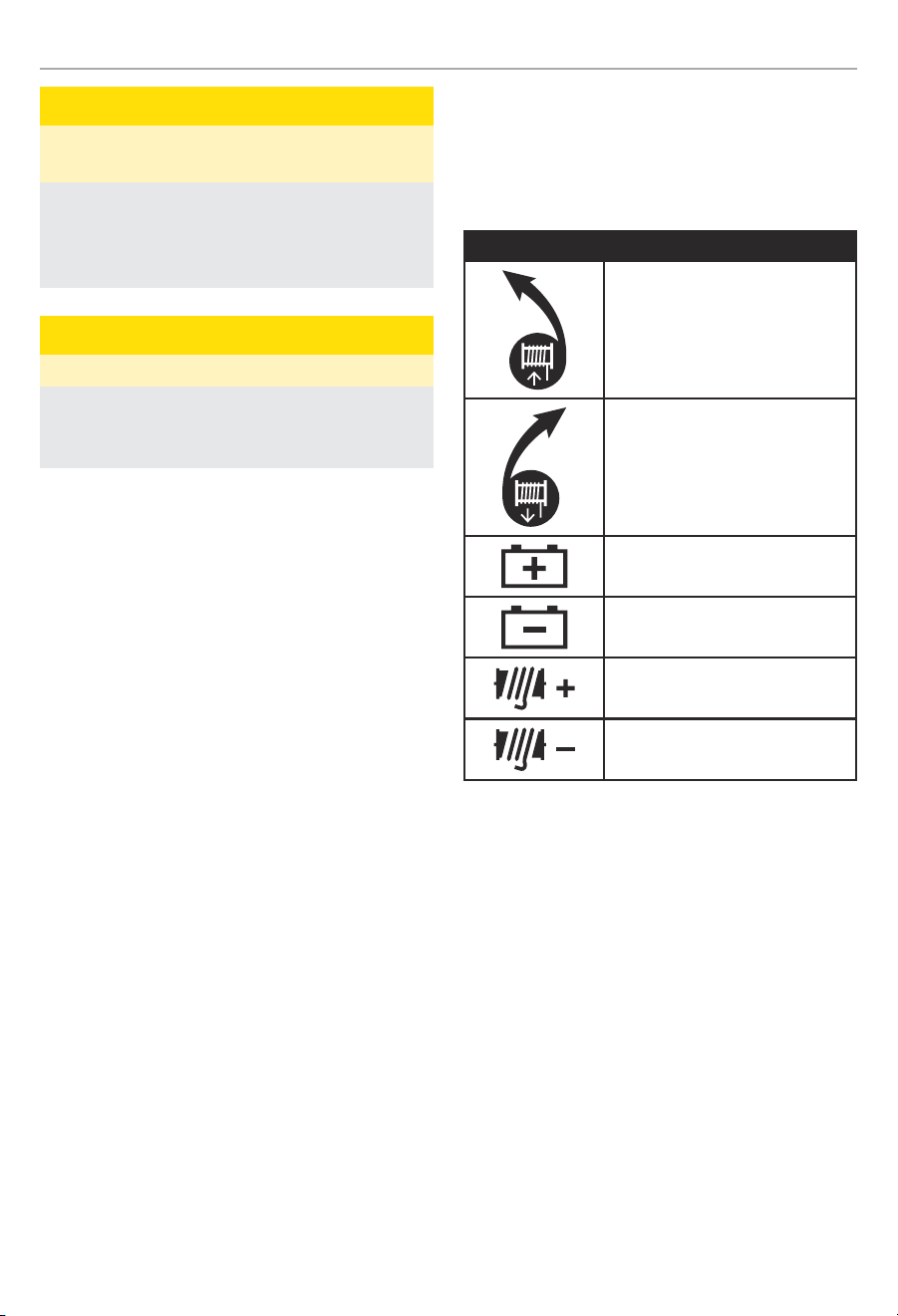
Operation Symbols
Some of the following symbols may be used on this
product. Please study them and learn their meaning.
Proper interpretation of these symbols will allow you to
more safely operate the product.
Symbol Meaning
Turn the clutch to the “IN” position
to retract the rope.
Turn the clutch to the “OUT”
position to release the rope.
Positive battery terminal
Negative battery terminal
Positive winch terminal
Negative winch terminal
100722 - 3500 LB. (1588 KG) WINCH
CONTROLS AND FEATURES
6
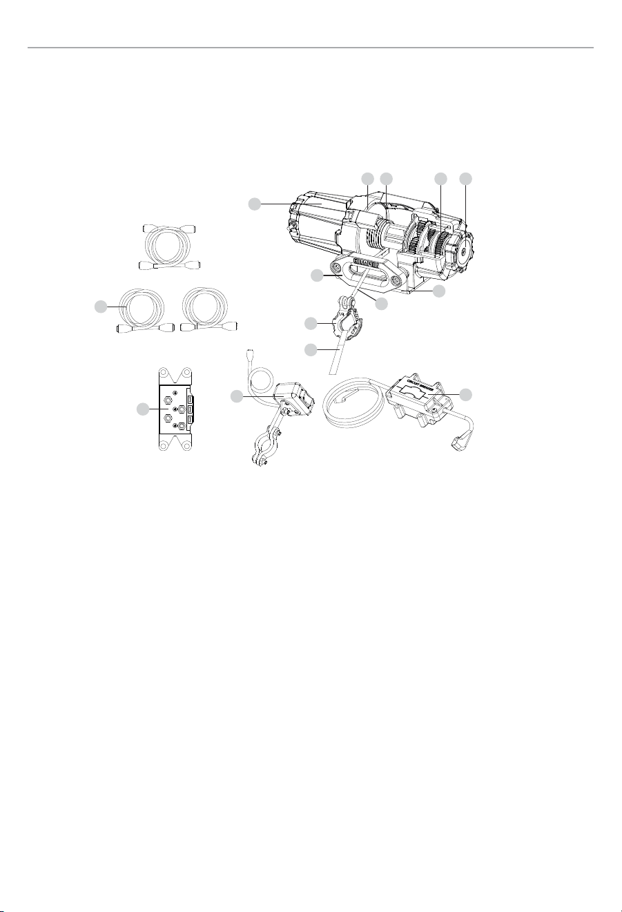
CONTROLS AND FEATURES
Read this operator’s manual before operating your winch. Familiarize yourself with the location and function of the
controls and features. Save this manual for future reference.
Winch
1. Motor – 1.2 HP (0.9 kW) 12V DC motor provides
power to the planetary gear mechanism.
2. Braking System – Braking action is automatically
applied to the winch drum when the winch motor is
stopped and there is a load on the synthetic rope.
3. Winch Drum – The winch drum is the cylinder
on which the synthetic rope is stored. It can feed
or wind the rope depending on the remote winch
switch.
4. Planetary Gear System – The reduction gears
convert the winch motor power into extreme pulling
forces. This system allows high torque while
maintaining compact size and light weight.
5. Free Spooling Clutch – The clutch allows the
operator to manually disengage (“Out”) the spooling
drum from the gear train, free spool. Engaging the
clutch (“In”) locks the winch into the gear system.
6. Mounting Channel
7. Circuit Breaker – The circuit breaker is installed
as close to the battery as possible to protect in the
event of an electrical fault. The assembly contains
two (2) thirty amp (30A) circuit breakers that are
a self-resetting, slow opening circuit breakers and
are designed to protect the winch motor from an
overweight pull or long full weight pull. They will
simply get hot and trip in the event of an electrical
fault. Once cooled down they will reset.
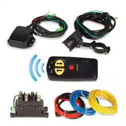
8. Rocker Switch – Rocker switch with handlebar
mount for powering the synthetic rope in or out of
your winch drum.
9. Solenoid/Contactor – Power from the vehicle
battery flows through the weather sealed contactor
before being directed to the winch motor.
10. Synthetic Rope – 3/16 in. × 50 ft.
(4.8 mm × 15.2 m) Synthetic rope designed
specifically for load capacity of 3,500 lb (1,588 kg).
The synthetic rope feeds onto the drum in the
“under wind” position through the Aluminum Hawse
and is looped at the end to accept the clevis hook
pin.
1
11
13
14
9
12
6
7
8
10
2 3 4 5

100722 - 3500 LB. (1588 KG) WINCH
CONTROLS AND FEATURES
7
11. Aluminum Hawse – When using the winch at
an angle the hawse acts to guide the synthetic
rope onto the drum and minimizes damage to the
synthetic rope from abrasion on the winch mount or
bumper.
12. Winch Connection Cables – Used to connect the
contactor to the winch motor.
13. Clevis Hook – Provides a means for connecting the
looped ends of cables to an anchor.
14. Strap – Used to assist synthetic rope feed.

100722 - 3500 LB. (1588 KG) WINCH
CONTROLS AND FEATURES
8
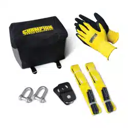
Parts Included
Assembly Parts
Part Part Qty Hardware
Hardware
Qty
Tool(s) Needed
Torque
lbf-ft
(N.m)
Winch Body 1
Hexagon Head Bolt M8 x 25 4 1x 13mm wrench or socket
6.1-7
(8.2-9.5)
Flat Washer Ø8 4
Lock washer Ø8 4
Mounting Channel 1
Aluminum Hawse 1
Hexagon Socket Set Screw
M10 x 25
2 1x 8mm allen wrench
11.8-12.6
(16-17.1)
Lock Nut M10 2 1x 16mm wrench or socket
Mini-Rocker Switch 1
Hexagon Socket Head
Screw M5 x 18
1 1x 4mm allen wrench
2.2-3
(3-4)
Hexagon Socket Head
Screw M5 x 25
2 1x 4mm allen wrench
2.2-3
(3-4)
Flat Washer Ø5 3
Nut M5 3 1x 8mm wrench or socket
Wire Tap 1
Contactor 1
Hexagon Head Bolt M6 x 25 4 1x 10mm wrench or socket
4.1-4.9
(5.6-6.6)
Flat Washer Ø6 4
Lock washer Ø6 4
Lock Nut M6 4 1x 10mm wrench or socket
Battery Wires -
Red (with Circuit
Breaker)
1
Battery Wires -
Black
1
Winch Wires -
Yellow
1
Winch Wires - Blue 1
Clevis Hook 1 Needle nose pliers
Yellow Strap 1
100722 - 3500 LB. (1588 KG) WINCH
ASSEMBLY
9
ASSEMBLY
Mounting the Winch
This CPE 3,500 lb (1,588 kg) winch is designed with a bolt
pattern that is standard in this class of winch. Many winch
mounting kits are available that utilize this bolt pattern for
the most popular trucks, SUV’s and ATV’s. If you cannot
find a kit locally, contact CPE and we will provide you with
the name of a dealer.
CAUTION
See Parts Included Assembly Parts section for torque
ratings. Mounting bolts must be SAE grade 5 or better
and torque to 34 ft. lbs (46 N.m).
1. Insert M10×25 (B) bolts through the mounting
channel (A) holes and attach the aluminum hawse
(D) to the mounting channel with the M10 lock nuts
(C) provided.
B
E
F
G
C
D
A
2. Turn the winch upside down. Place the mounting
channel on the winch, making sure the winch is
centered in the middle of it.
3. Thread the M8×25 (E) bolts through the Ø8 lock (F)
and flat washers (G), and then thread through the
mounting channel. Tighten the bolts. DO NOT over
tighten.
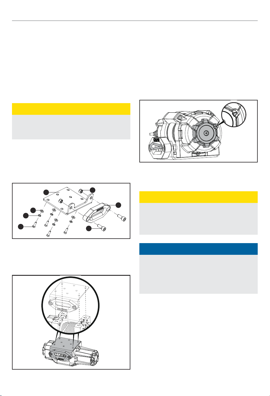
4. Turn winch right side up. Disengage the clutch by
moving the Cam Clutch Gear to the “Out” position
- the arrow on the Cam Clutch Gear would be to the
back of the winch as shown. Release the synthetic
rope and pull through the aluminum hawse.
Out
5. Attach the clevis hook to the synthetic rope, and
then the hand strap to the clevis hook.
CAUTION
If utilizing a mounting plate, ensure that the three
major sections (motor, drum and gear housing) are
properly aligned. Proper alignment of the winch will
allow for even distribution of the full rated load.
NOTICE
The type of vehicle to which the winch and mounting
channel will be applied, will dictate the type of
mounting kit that should be used (Speed Mount™
Hitch Adapter, Standard Mounting Channel, or
Specialty Mounting Kit).
Solenoid/Contactor Location
Find a location for the solenoid/contactor. It is
recommended that the solenoid/contactor be mounted
close to the battery in a clean, dry location. Make sure the
location chosen allows for sufficient clearance from all
metal components. Drill mounting holes if required. Once
a location is found, DO NOT install the unit until all wiring
is completed (see wiring section).

100722 - 3500 LB. (1588 KG) WINCH
ASSEMBLY
10
NOTICE
Terminals coming in contact with metal will cause a
direct short, possibly causing solenoid/contactor and/
or battery damage.
Install the Rocker Switch
1. Decide which handlebar the rocker switch will be
mounted on. (The rocker switch is usually installed
on the left handlebar).
2. Use a piece of electrical tape (not provided) around
the handlebar to help prevent rotation of the mount.
3. Tighten the rocker switch in place. DO NOT
overtighten or tighten/clamp over any hoses or
cables.
4. Once the rocker switch is mounted, the wires can
be routed back to where the solenoid/contactor is
located.
5. Make sure the handlebars have full range of motion
and then secure the rocker switch’s cable with the
supplied cable ties.
Wiring the Winch
CAUTION
NEVER route electrical cables across any sharp edges,
through and/or near moving parts, or near parts that
may become hot.
CAUTION
Battery cables should NOT be drawn tight. Leave some
slack for cable movement.
NOTICE
You may need to use a test light to locate a suitable
wire. The wire should only have power when the key is
in the ON position.
NOTICE
Depending on the location of the solenoid/contactor,
you may need to use the black and red cables in place
of the yellow and blue, and the yellow and blue in place
of the red and black.
1. See the Wiring Diagram on the following page for
these following steps. Connect the yellow and blue
cables to the motor terminals on the winch. (Yellow
to the positive (+) terminal of the motor. Blue to
the negative (-) terminal of the motor). Tighten the
terminal nuts on the motor. DO NOT over tighten.
Route the other ends to the solenoid/contactor
location.
2. Connect the yellow and blue cables to the solenoid/
contactor (yellow to yellow and blue to blue).
DO NOT tighten nuts.
3. Connect the red and black cables to the solenoid/
contactor (red to red and black to black). DO NOT
tighten nuts. Route the other ends to the vehicle’s
battery.
4. Connect the shorter red lead to the positive (+)
terminal of the vehicle’s 12 volt battery. Connect
the other longer red lead to the solenoid/contactor.
Use the supplied cable ties to attached the circuit
breaker assembly where convenient.
5. Connect the rocker switch to the solenoid/contactor
(black to black and green to green).
6. Splice the end of the red wire on the rocker switch,
to an ignition (keyed) controlled power source using
the supplied wire tap.
7. Once all wiring is connected to the solenoid/
contactor it can then be mounted using the supplied
M6 hardware.
8. Tighten the solenoid/contactor terminal nuts.
DO NOT over tighten.
9. Connect the black lead to the negative (-) terminal of
the vehicle’s 12 volt battery.
10. Place all terminal boots over terminals and secure
all cables with cable ties or electrical tape (not
included).
100722 - 3500 LB. (1588 KG) WINCH
ASSEMBLY
11
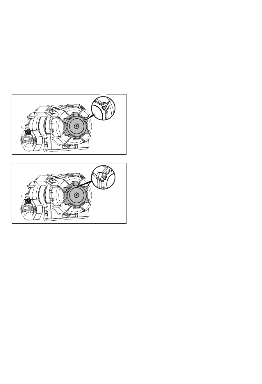
11. Check for proper drum rotation. Turn the clutch
knob to the “Out” position (free spooling). Pull out
some cable from the drum, and then turn the clutch
knob to the “In” position to engage the gears. Press
the cable out button on the rocker switch. If the
drum is turning and releasing more cable, then your
connections are accurate. If the drum is turning and
collecting more cable then reverse the leads on the
motor. Repeat and check rotation.
Out
In
100722 - 3500 LB. (1588 KG) WINCH
ASSEMBLY
12
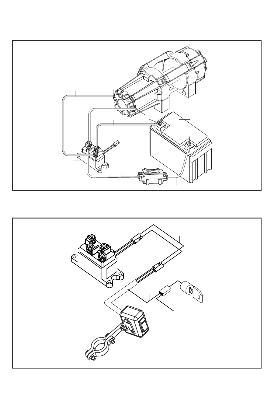
Wiring Diagram
Blue
to switch and
remote wiring
Yellow
Black
Longer Red Lead
Positive (+)
Positive (+)
Negative (–)
Switch Wiring Diagram
Black
Green
Red
Ignition Wire
Solenoid/Contactor
Battery
Circuit Breaker Assembly
Shorter Red Lead
100722 - 3500 LB. (1588 KG) WINCH
OPERATION
13
OPERATION
General Tips for Safe Operation
Your 100722 winch is rated at a 3,500 lb (1,588 kg)
capacity in first layer (max) when spooling the first rope
layer on the drum. Overloads can damage the winch,
motor and/or synthetic rope. For loads over 1,750 lb.
(794 kg) we recommend the use of the pulley block/
snatch block to double the synthetic rope line. This will
aid in two ways:
– reduce the number or rope layers on the drum,
as well as,
– reduce the load on the rope by as much as 50%.
When doubling the line back to the vehicle, attach to the
tow hook, frame or other load bearing part. The vehicle
engine should be kept running during operation of the
winch to minimize battery drain and maximize power and
speed of the winch. If the winch is used for a considerable
time with the engine off the battery may be drained and
too weak to restart the motor.
Get to know your winch before you actually need to use
it. We recommend that you set up a few test runs to
familiarize yourself with rigging techniques, the sounds
your winch makes under various loads, the way the rope
spools on the drum, etc.
Inspect the synthetic rope and equipment before
each use. A frayed or damaged rope shall be replaced
immediately. Use only manufacturer’s identical
replacement rope with the exact specifications.
Inspect the winch installation and bolts to ensure that all
bolts are tight before each operation. Store the remote
control inside your vehicle in a place that it will not be
damaged.
Any winch that appears to be damaged in any way,
is found to be worn, or operates abnormally MUST
BE REMOVED FROM SERVICE UNTIL REPAIRED. It is
recommended that the necessary repairs be made by a
manufacturer’s authorized repair facility.
Pull only on areas of the vehicle as specified by the
vehicle manufacturer. Only attachments and/or adapters
supplied by the manufacturer are to be used.
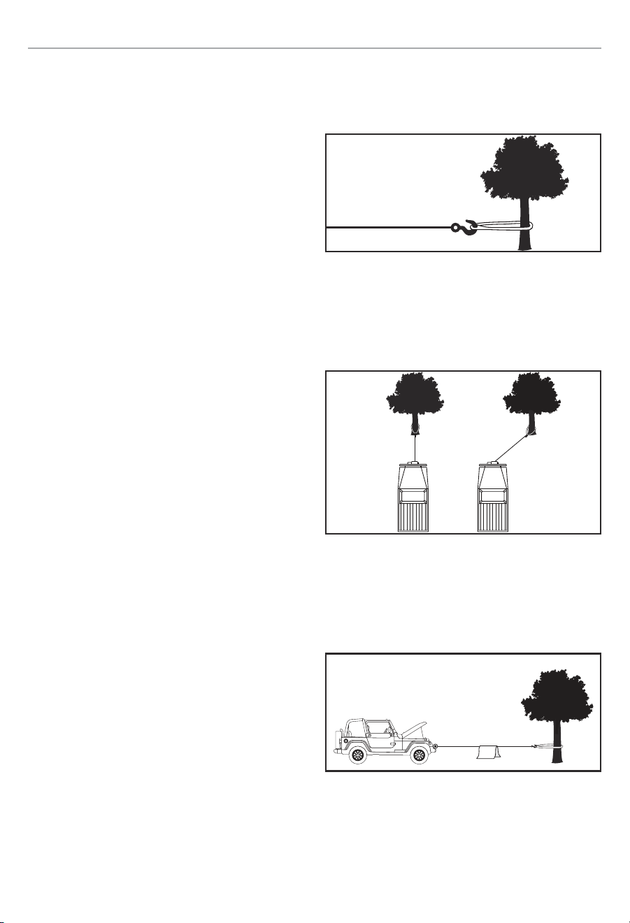
Self Recovery
Locate a suitable anchor such as a strong tree trunk or
boulder. Always use a sling as an anchor point.
Your winch is equipped with a aluminum hawse to help
guide the synthetic rope and to reduce binding on short
side pulls. Do not winch from an acute angle as the
synthetic rope will pile up on one side of the drum causing
damage to synthetic rope and the winch.
Correct Incorrect
Short pulls from an angle can be used to straighten the
vehicle. Long pulls should be done with the synthetic rope
at a 90° angle to the winch/vehicle. When pulling a heavy
load, place a blanket or jacket over the synthetic rope five
or six feet from the hook.
In the event of a broken cable it will dampen the snap
back. For additional protection open the hood of the
vehicle. For pulls over 1,750 lb. (794 kg), we recommend
the use of the snatch block/pulley block to double line the
synthetic rope.
100722 - 3500 LB. (1588 KG) WINCH
OPERATION
14
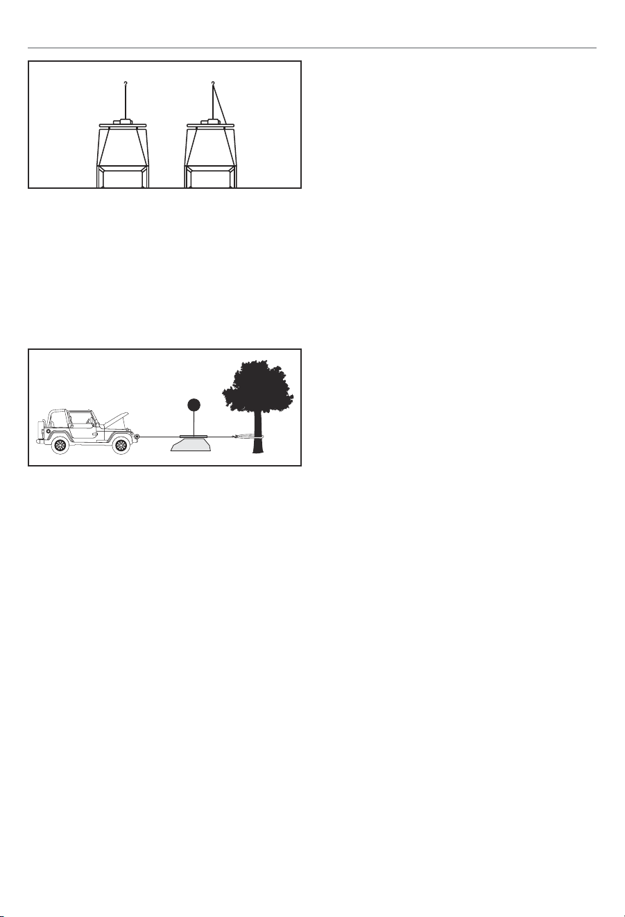
Single Line Double Line
This reduces the load on the winch and the strain on the
rope by approximately 50%.
Synthetic Rope Abrasion Sleeve
The winch should be set up to avoid any rough surface
from contacting the rope. If that is not possible, the
abrasion sleeve can be used to help protect the rope (A).
A
Winching Techniques A-Z
A. Take time to assess your situation and plan your pull.
B. Put on gloves to protect your hands.
C. Disengage the clutch to allow free-spooling and also
save battery power.
D. Attach the hook strap to the clevis hook.
E. Pull out the synthetic rope to your desired anchor
point using the hook strap.
F. Secure the clevis hook to the anchor point: Sling,
chain or snatch block. Do not attach the hook back
onto the synthetic rope.
G. Engage the clutch.
H. Connect the remote control to the winch. If you are
going to control the winch from inside your vehicle
then pass the remote through an open window to
avoid the wires being pinched in the door.
I. Start your engine to ensure power is being
replenished to the battery.
J. Drape a blanket or jacket over the synthetic rope
approximately 5 to 6 feet from the hook. Open the
hood for added protection.
K. Power in the synthetic rope guiding the rope under
tension to draw up the slack in the rope. Once the
rope is under tension, stand clear. Never step over
the synthetic rope.
L. Double check your anchors and make sure all
connections are secure.
M. Inspect the synthetic rope. Make sure there are at
least 5 wraps of synthetic rope around the winch
drum.
N. Clear the area. Make sure all spectators stand clear
and that no one is directly in front or behind the
vehicle or anchor point.
O. Begin winching. Be sure that the synthetic rope is
winding evenly and tightly around the drum. The
vehicle that is being winched can be slowly driven to
add assistance to the winching process. Avoid shock
loads; keep the synthetic rope under tension.
P. The vehicle to be winched should be placed in
neutral and the emergency brake released. Only
release the brake pedal when under full tension.
Avoid shock loads to the winch. This can damage the
winch, rope and vehicle.
Q. The winch is meant for intermittent use. Under full
load with a single line rig do not power in for more
than a minute without letting the motor cool down
for a few minutes and then resume the winching
operation.
R. The winching operation is complete once the vehicle
is on stable ground and is able to drive under its own
power.
S. Secure the vehicle. Be sure to set the brakes and
place the vehicle in park.
T. Release the tension on the synthetic rope. The winch
is not meant to hold the vehicle for long periods of
time.
U. Disconnect the synthetic rope from the anchor.
V. Rewind the synthetic rope. Make sure that any rope
already on the drum has spooled tightly and neatly.
If not, draw out the rope and re-spool from the point
where the rope is tight.

100722 - 3500 LB. (1588 KG) WINCH
MAINTENANCE
15
W. Keep your hands clear of the winch drum and hawse
as the synthetic rope is being drawn in.
X. Secure the hook and hook strap.
Y. Disconnect the remote control and store in a clean,
dry place.
Z. Clean and inspect connections and mounting
hardware for next winching operation.
MAINTENANCE
The owner/operator is responsible for all periodic
maintenance.
WARNING
Never operate a damaged or defective winch.
WARNING
Improper maintenance will void your warranty.
Complete all scheduled maintenance in a timely manner.
Correct any issue before operating the winch.
NOTICE
For service or parts assistance, contact our help line at
1-877-338-0999
Lubrication
All moving parts within the Electric Winch having been
Lubricated using high temperature lithium grease at the
factory. No internal lubrication is required. Lubricate
Cable Assembly periodically using a light penetrating oil.
Synthetic Rope Replacement
It is recommended that any modifications be performed
by a manufacturer’s authorized repair facility, and that
only manufacturer-supplied parts be used.
1. Move the clutch to the “Out” position.
2. Extend Synthetic Rope to its full length. Note how
the existing rope is connected to the inside of the
drum.
3. Remove old Synthetic Rope and attach new one.
4. Retract Synthetic Rope onto drum being careful not
to allow kinking.
Synthetic Rope
Periodically rinse the synthetic rope with water to remove
any sand, dirt, mud, or debris that can become embedded
or build up in the rope during use. This will help extend
the life of the rope.
NOTICE
Inspect rope before and after each use. If rope
becomes frayed it must be replaced.

100722 - 3500 LB. (1588 KG) WINCH
SPECIFICATIONS
16
SPECIFICATIONS
Performance Specifications
Winch Model
...............................100722
Rated Pull ....................... 3,500 lb (1,588 kg)
Gear Reduction Ratio ......................... 180:1
Motor........................... Permanent Magnet
........................... 1.2 HP (0.9 kW) (12V DC)
Duty Cycle ............................. Intermittent
Drum Size .....................1.7 in. (D) × 3.2 in. (L)
.......................... [44.5 mm(D) × 81 mm(L)]
Synthetic Rope ............... 3/16 in. (D) × 50 ft. (L)
............................[4.8 mm(D) × 15.2 m(L)]
Gross Weight
.......................27.3 lb. (12.4 kg)
Net Weight .......................... 24 lb. (10.9 kg)
Height ...............................5 in. (12.6 cm)
Width .............................. 4.8 in. (12.1 cm)
Length ............................. 13.8 in. (35 cm)
Bolt Pattern ......... 4.9 in. × 3 in. (12.4 cm × 7.6 cm)
IP Rating ......... IP68 Water and Dust Proofing Rated
Line Speed and Motor Current (First Layer)
Line Pull
LB 0 1000 2000 2500 3500
KG 0 454 907 1134 1588
Line Speed (12V DC)
FPM 12.1 10.8 8.2 7.5 4.9
MPM 3.7 3.3 2.5 2.3 1.5
Motor Current (12V DC) A 28 60 90 105 130
Running Time* Minutes 5 5 5 5 5
Cooling Time** Minutes 5 5 5 5 5
Line Pull and Cable Capacity Per Layer
Line of Cable 1 2 3 4 5
Rated Line Pull
LB 3500 2927 2517 2207 1966
KG 1588 1329 1143 1002 892
Cable Capacity
FT 7.6 16.7 27.3 39.4 50
M 2.3 5.0 8.3 12.0 15.2
* If the motor becomes uncomfortably hot to the touch, stop winching immediately and let it cool down for 5 minutes.
Do not pull for more than one minute at or near the rated load.
* *Electric winches are designed and made for intermittent use and should not be used in constant duty applications.
It is recommended to use double line and snatch block for pulling loads over 1,750 lb. (794 kg).

100722 - 3500 LB. (1588 KG) WINCH
TROUBLESHOOTING
17
TROUBLESHOOTING
Problem Cause Solution
Motor does not turn on
Loose battery cable connections Tighten nuts on all cable connections
Defective Switch Assembly Replace Switch Assembly
Defective motor
Check for voltage at armature port with Switch
pressed. If voltage is present, Replace motor
Water has entered motor
Check for voltage at armature port with Switch
pressed. If voltage is present, Replace motor
Motor runs but Cable drum
does not turn
Clutch not engaged
Move Clutch to the “In” position. If problem
persists, a qualified technician needs to check and
repair.
Motor runs slowly or
without normal power
Insufficient current or voltage
The battery is weak, recharge. Run winch with
vehicle motor running (Battery should have a
strong charge)
Loose or corroded battery cable
connections.
Clean, Tighten, or replace
Motor overheating Winch running time too long Allow winch to cool down periodically
Motor runs in one direction
only
Defective Switch Assembly Replace Switch Assembly
For further technical support:
Technical Support Team
Toll Free 1-877-338-0999
support@championpowerequipment.com

WARRANTY*
CHAMPION POWER EQUIPMENT
2 YEAR LIMITED WARRANTY
Warranty Qualifications
To register your product for warranty and FREE lifetime
call center technical support please visit:
https://www.championpowerequipment.com/register
To complete registration you will need to include a copy
of the purchase receipt as proof of original purchase.
Proof of purchase is required for warranty service.
Please register within ten (10) days from date of
purchase.
Repair/Replacement Warranty
CPE warrants to the original purchaser that the
mechanical and electrical components will be free of
defects in material and workmanship for a period of
two years (parts and labor) from the original date of
purchase and 180 days (parts and labor) for commercial
and industrial use. Transportation charges on product
submitted for repair or replacement under this warranty
are the sole responsibility of the purchaser. This
warranty only applies to the original purchaser and is not
transferable.
Do Not Return The Unit To The Place
Of Purchase
Contact CPE’s Technical Service and CPE will
troubleshoot any issue via phone or e-mail. If the
problem is not corrected by this method, CPE may,
at its option, authorize other means of repair and/or
replacement.
Warranty Exclusions
This warranty does not cover the following repairs and
equipment:
Normal Wear
Products with mechanical and electrical components
need periodic parts and service to perform well. This
warranty does not cover repair when normal use has
exhausted the life of a part or the equipment as a whole.
Installation, Use and Maintenance
This warranty will not apply to parts and/or labor if the
product is deemed to have been misused, neglected,
involved in an accident, abused, loaded beyond the
product’s limits, modified, installed improperly or
connected incorrectly to any electrical component.
Normal maintenance is not covered by this warranty
and is not required to be performed at a facility or by a
person authorized by CPE.
Other Exclusions
This warranty excludes:
– Cosmetic defects such as paint, decals, etc.
– Wear items such as winch cable, etc.
– Accessory parts such as storage covers.
– Failures due to acts of God and other force majeure
events beyond the manufacturer’s control.
– Problems caused by parts that are not original
Champion Power Equipment parts.
Limits of Implied Warranty and
Consequential Damage
Champion Power Equipment disclaims any obligation to
cover any loss of time, use of this product, freight, or any
incidental or consequential claim by anyone from using
this product. THIS WARRANTY IS IN LIEU OF ALL OTHER
WARRANTIES, EXPRESS OR IMPLIED, INCLUDING
WARRANTIES OF MERCHANTABILITY OR FITNESS FOR
A PARTICULAR PURPOSE.
A unit provided as an exchange will be subject to the
warranty of the original unit. The length of the warranty
governing the exchanged unit will remain calculated by
reference to the purchase date of the original unit.
This warranty gives you certain legal rights which may
change from state to state or province to province. Your
state or province may also have other rights you may be
entitled to that are not listed within this warranty.
Contact Information
Address
Champion Power Equipment, Inc.
12039 Smith Ave.
Santa Fe Springs, CA 90670 USA
www.championpowerequipment.com
Customer Service
Toll Free: 1-877-338-0999
info@championpowerequipment.com
Fax no.: 1-562-236-9429
Technical Service
Toll Free: 1-877-338-0999
tech@championpowerequipment.com
EMERGENCY 24 HOUR SUPPORT: 1-562-204-1188