1
NOTE TO CONSUMER: DO NOT DESTROY THIS MANUAL. PLEASE READ CAREFULLY AND KEEP ALL INSTRUCTIONS
FOR FUTURE REFERENCE.
CONDENSING
TANKLESS
COMBI BOILER
Use and Care Manual
User’s Information
Installation
Start-Up
Maintenance
Parts
100K Heating (180K DHW) Btu/h Models
120K Heating (199K DHW) Btu/h Models
WARNING
WARNING
The surfaces of these products contacted by consumable water contain less than 0.25% lead by weight, as
required by the Safe Drinking Water Act, Section 1417.
injury or death.
WHAT TO DO IF YOU SMELL GAS
: Cancer and Reproductive Harm - www.P65Warnings.ca.gov.
AP20
2
WARNING: If you do not follow these instructions exactly, a fire or explosion
may result, causing property damage, personal injury or death.
A.This appliance does not have a pilot. It is equipped
with an ignition device automatically lights the
burner. Do not try to light the burner by hand.
B. BEFORE OPERATING smells all around the
appliance area for gas. Be sure to smell next to the
floor because some gas is heavier than air and will
settle on the floor.
WHAT TO DO IF YOU SMELL GAS
Do not try to light any appliance
Do not touch any electric switch;
do not use any phone in your building
If you cannot reach your gas supplier, call the
fire department.
C. Use only your hand to turn the gas control knob.
Never use tools. If the handle will not turn by hand,
don’t try to repair it, call a qualified service
technician. Force or attempted repair may result in a
fire or explosion.
D. Do not use this appliance if any part has been
under water. Immediately call a qualified service
technician to inspect the appliance and to replace
any part of the control system and any gas control
which has been under water.
OPERATING INSTRUCTIONS
1.STOP! Read the safety information above.
2. Set the thermostat to lowest setting.
3. Turn off all electric power to the appliance.
4. This appliance is equipped with an ignition device
which automatically lights the burner. Do not try to
light the burner by hand.
5. Remove front cover.
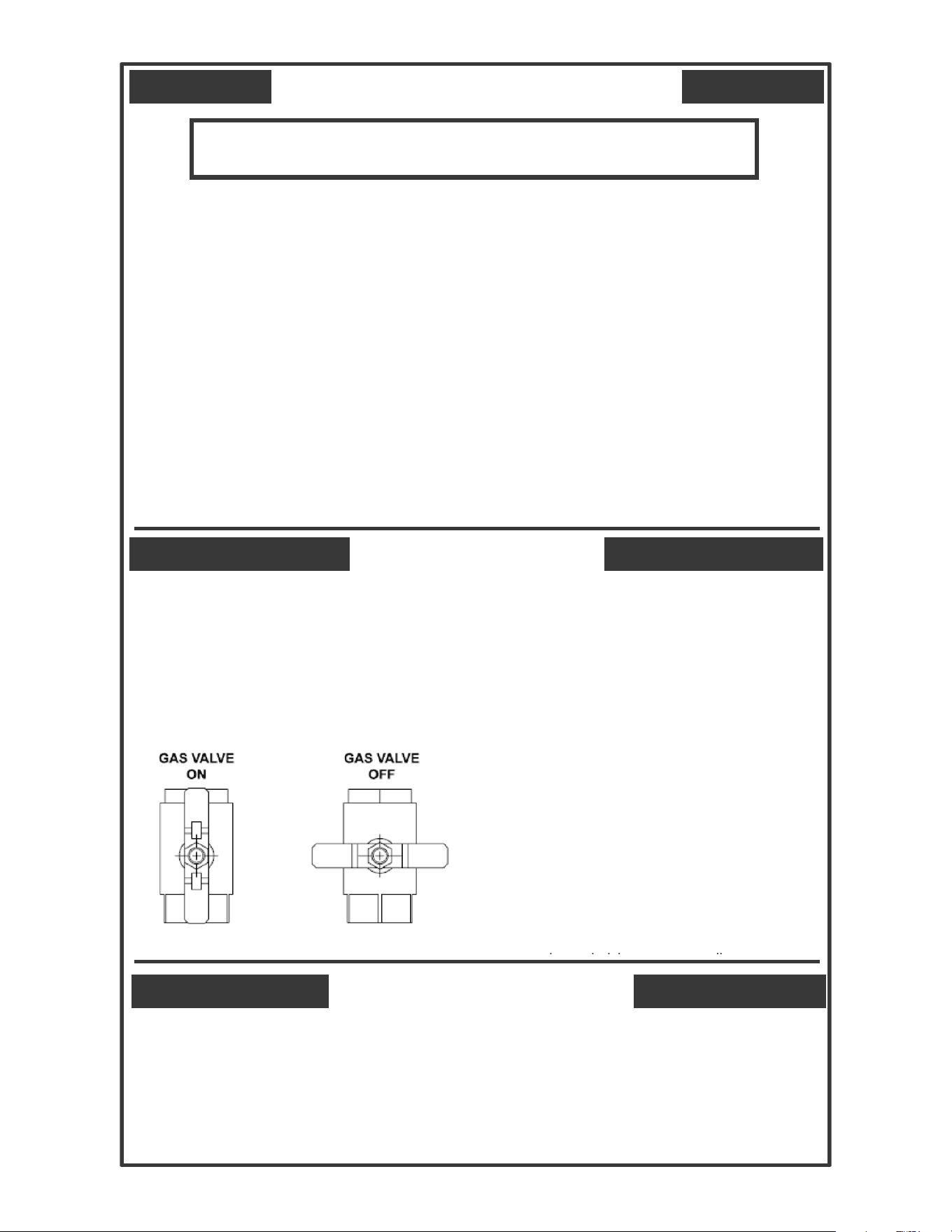
6. Turn gas shutoff valve to “off”. Handle will be
across the piping, do not force.
7. Wait five (5) minutes to clear out any gas. If you
then smell gas, STOP! Follow “B” in the safety
information above on this label. If you don’t smell
gas, go to next step.
8. Turn gas shutoff valve to “on”. Handle will be in
line with piping.
9. Install front cover.
10. Turn on all electric power to appliance.
11. Set thermostat to desired setting.
12. If the appliance will not operate, follow the
instructions “To Turn Off Gas To Appliance” and call
your service technician or gas supplier.
i h i i li
TO TURN OFF GAS TO APPLIANCE
1. Set the thermostat to lowest setting.
2. Turn off all electric power to the appliance if service
is to be performed.
3. Remove front cover.
4. Turn gas shutoff valve “off”. Handle will be across
the piping. Do not force.
5. Install front cover.
FOR YOUR SAFETY READ BEFORE OPERATING
smell
electrical switch
electrical power to the appliance.
electrical power to the appliance.
electrical power to the appliance if
3
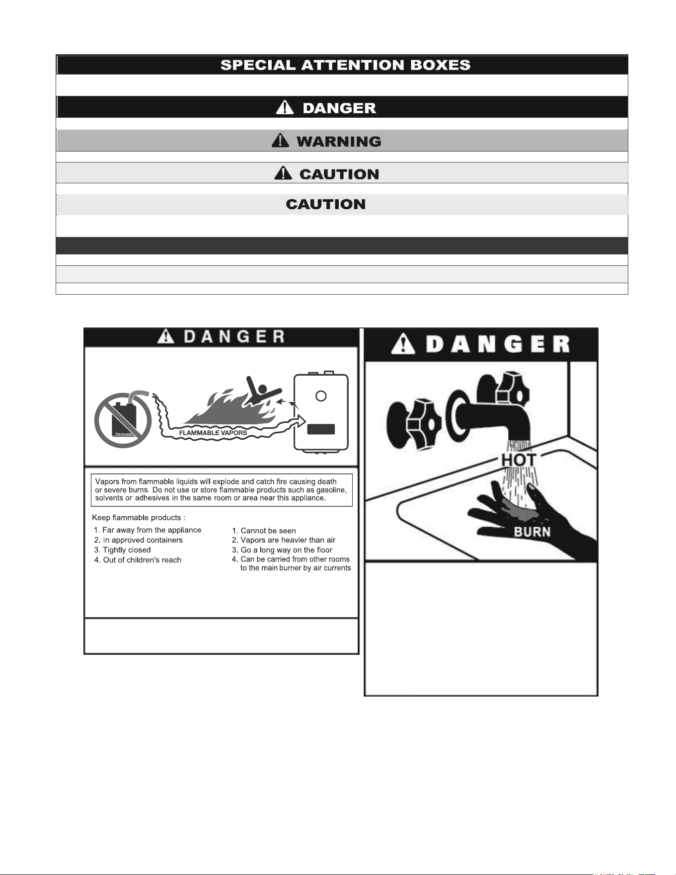
The following defined terms are used throughout this manual to bring attention to the presence of hazards of various risk
levels, or to important product information.
DANGER indicates an imminently hazardous situation which, if not avoided, will result in death or serious injury.
WARNING indicates a potentially hazardous situation which, if not avoided, could result in death or serious injury.
CAUTION indicates a potentially hazardous situation which, if not avoided, may result in minor or moderate injury .
CAUTION used without the safety alert symbol indicates a potentially hazardous situation which, if not avoided, may result in property
damage.
NOTICE
NOTICE is used to address practices not related to personal injury.
SAFETY INSTRUCTIONS
SAFETY INSTRUCTIONS (or equivalent) signs indicate specific safety related instructions or procedures.
NOTE: Contains additional information important to a procedure.
"
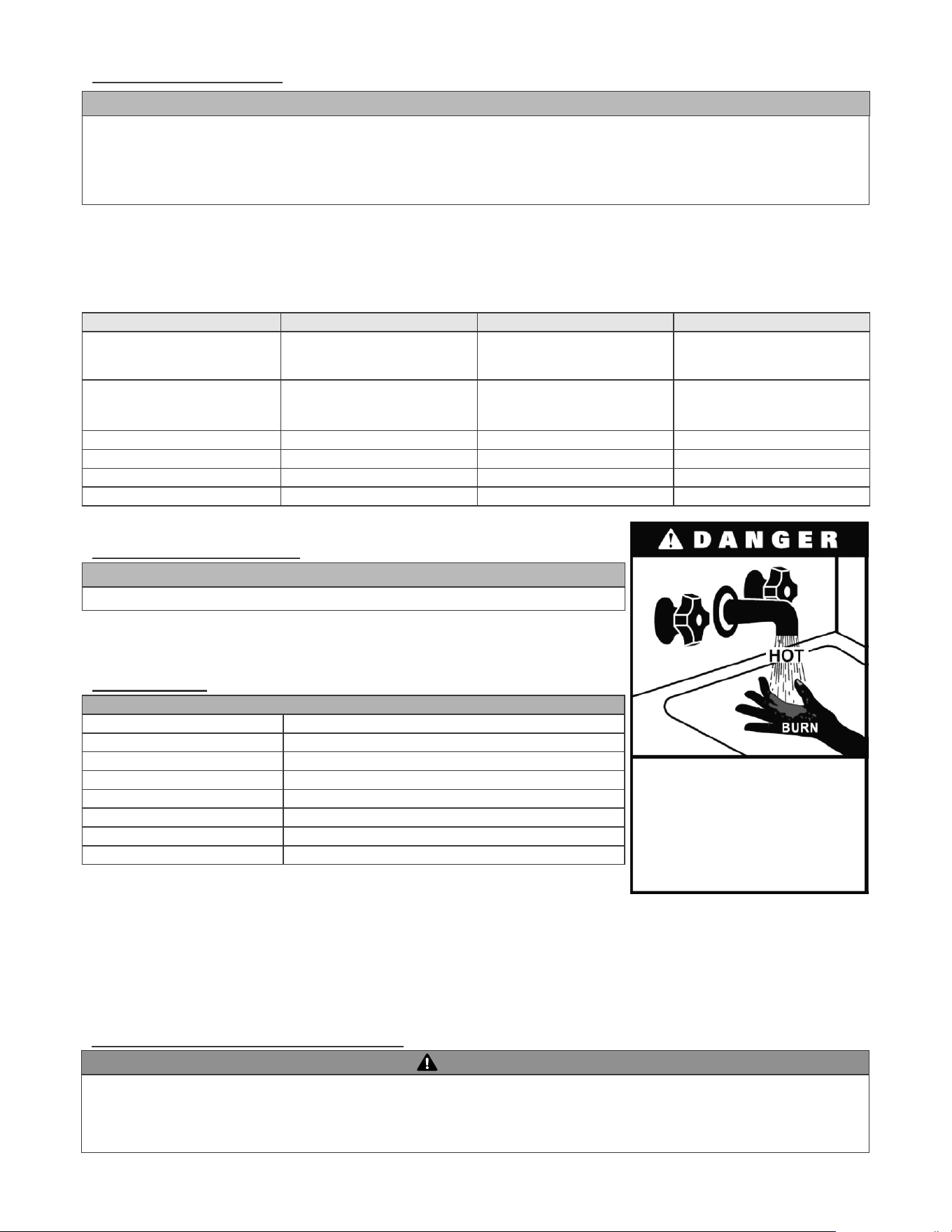
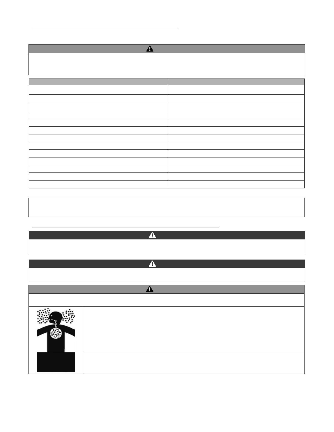
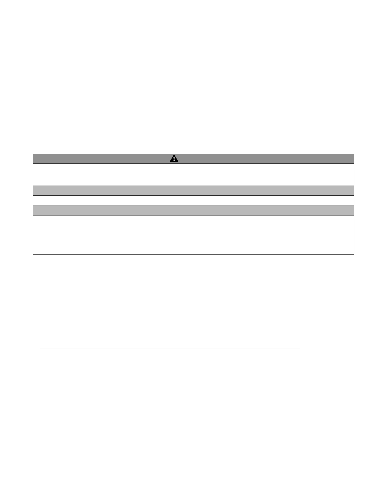
Water Temperature over 125°F can cause
severe burns instantly or death from scalds.
Children, disabled and
elderly are at highest risk of being scalded.
See instruction manual before setting the DHW
temperature at the Combi Boiler.
Feel water before bathing or showering.
Temperature limiting valves are available, see
manual.
Vapors
4
FOREWORD
Authority Having Jurisdiction (AHJ) –
NOTE:
FOR THE INSTALLER
ANSI Z223.1-Latest Edition.
INSTALLATIONS MUST COMPLY WITH:
DANGER
WARNING
The hydronic supply and return connections of these products are for installation in closed loop systems ONLY! Use of this product in
IS NOT COVERED BY WARRANTY.
NOTE:

PART 1 – ITEMS SHIPPED WITH THE APPLIANCE
PART 2 – SAFETY REGULATIONS
C. GAS......................................................................................................................................................................9
PART 3 – TECHNICAL SPECIFICATIONS..............................................................................................................11
PART 4 – PREPARE APPLIANCE LOCATION......................................................................................................13
E
.............................................
..
.................
..........................
PART 5 – VENTING.........................................................................................................................................................19
3. Screen Installation.........................................................................................................................
.....
PART 6 – INSTALL THE CONDENSATE DRAIN
PART 7 – GAS PIPING...................................................................................................................................................29
PART 8 – WATER PIPING.............................................................................................................................................32
PART 9 – CONNECT ELECTRICAL POWER / INITIAL STARTUP
...............
.....39

PART 10 – OPERATING SYSTEM INSTRUCTIONS
PART 11 – START-UP PREPARATION
PART 12 – INSTALLATION AND START-UP CHECKLIST
PART 13 – TROUBLESHOOTING
PART 14 – ANNUAL MAINTENANCE PROCEDURES
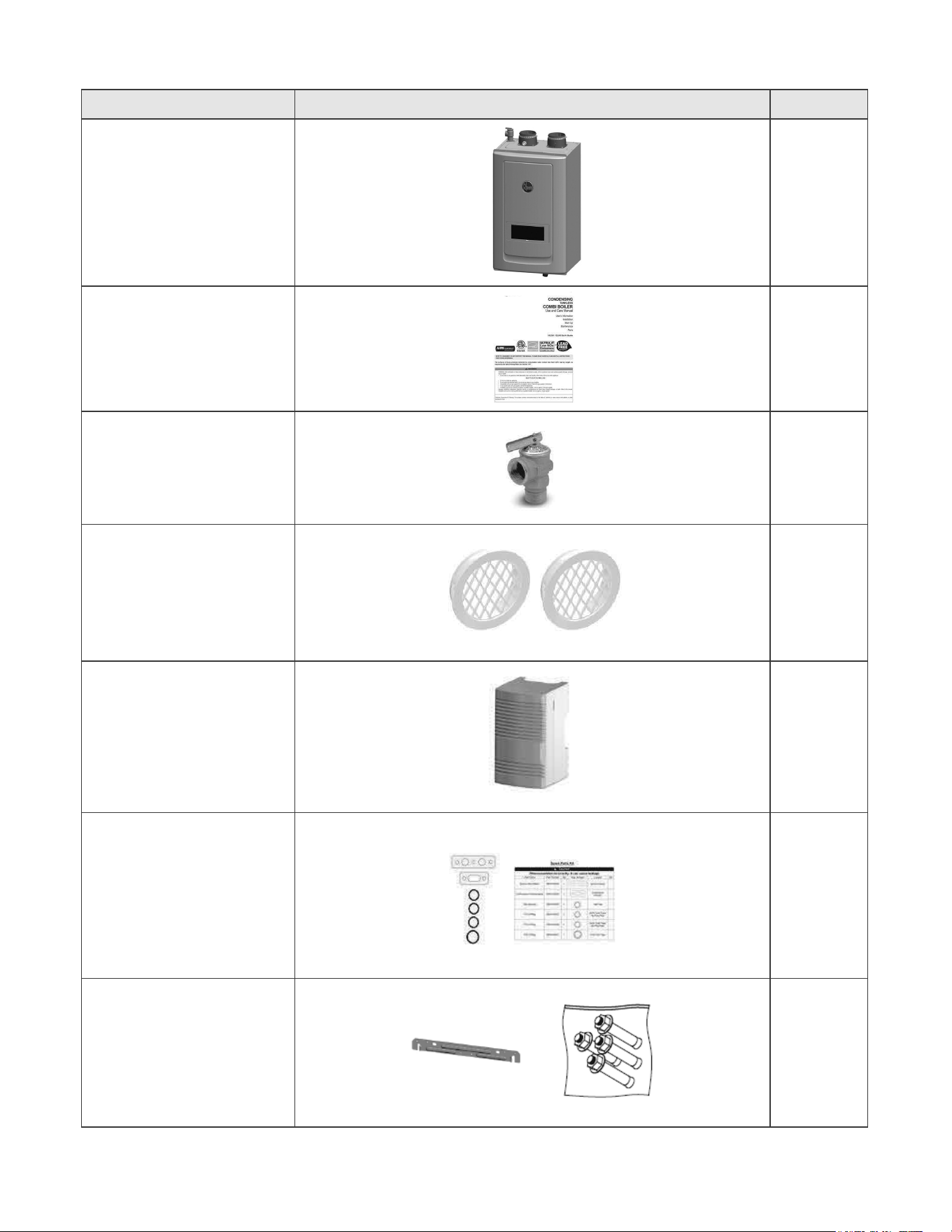
PART 1 – ITEMS SHIPPED WITH THE APPLIANCE
ITEM DESCRIPTION QUANTITY
1
Use and Care Manual 1
1
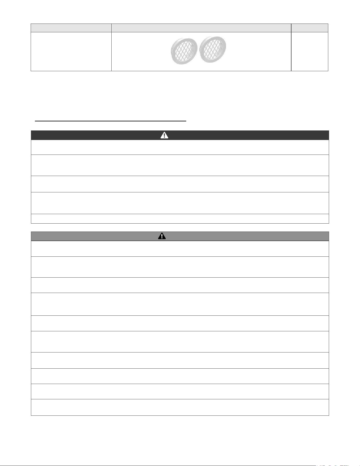
2 Screens
1
1
1
PART 2 –SAFETY REGULATIONS
ITEM DESCRIPTION PART NUMBER
2 Screens
Table 1 – Items Included with the Appliance
ƓA. OPERATION AND INSTALLATION WARNINGS
DANGER
WARNING
open and functional.
port.
9
WARNING
WARNING
WARNING
CAUTION
NOTICE
ƓB. IMPROPER COMBUSTION
ƓC. GAS
ƓD. WHEN SERVICING THE APPLIANCE
ㆍ
ㆍ
ㆍ
ㆍ
DO NOT USE THIS APPLIANCE IF ANY PART HAS BEEN SUBMERGED IN WATER.
NOTE:
and accelerated component failure. Rheem DOES NOTDO NOT
controls.
¶¶
2. DAMAGE
NOTE:
ƓE. WATER CHEMISTRY
ƓF. FREEZE PROTECTION
ƓG. SCALDING
professional.
CAUTION
CAUTION
¶m
Contaminant Contaminant
Aluminum Sulfate
Chloride
Copper Zinc
Iron
2
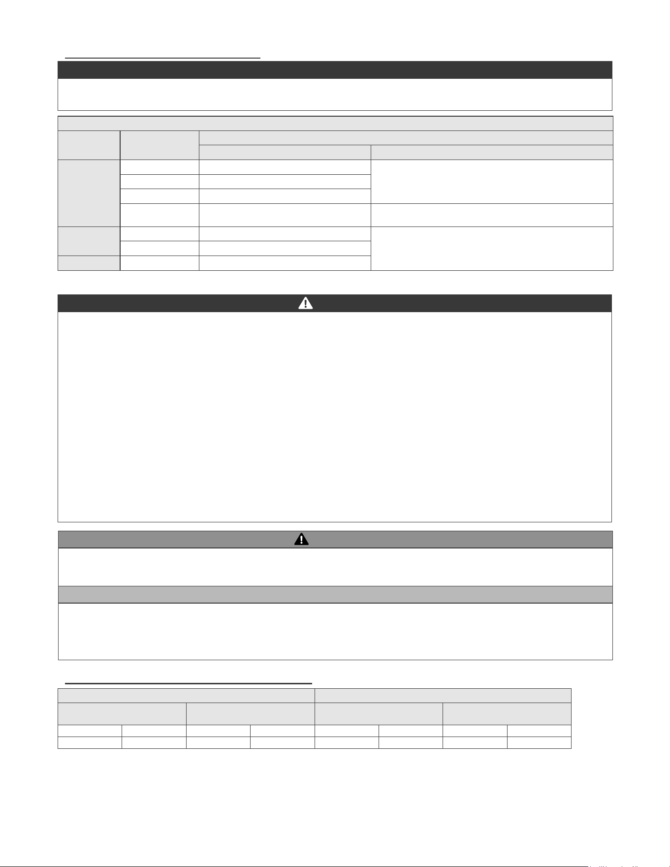
7DEOH²:DWHU&KHPLVWU\6SHFLÀFDWLRQV
Table 3 – Time and Temperature Relationship in Scalds
APPROXIMATE TIME / TEMPERATURE RELATIONSHIPS IN SCALDS
1 ½ to 2 minutes
Less than 3 seconds
NOT
these appliances, you may create the potential for scald injury.
temperature for your applications.
manual.
WARNING
ƓH. HIGH ELEVATION INSTALLATIONS
LP Gas.
11
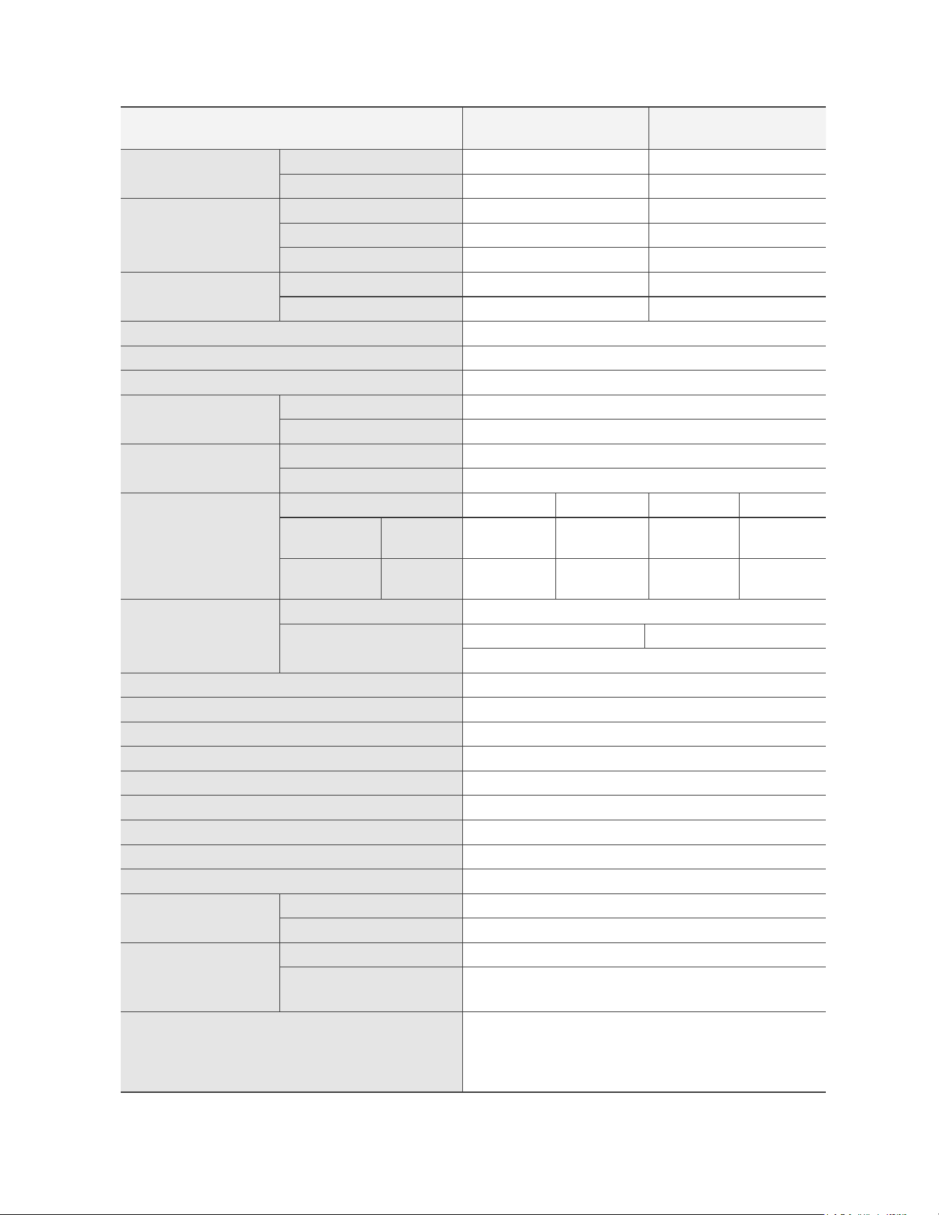
7DEOH²7HFKQLFDO6SHFLÀFDWLRQV
PART 3 –TECHNICAL SPECIFICATIONS
0RGHO
.+HDWLQJ
.'+:%WXKU
.+HDWLQJ
.'+:%WXKU
Gas Input Rate
MAX
MIN
Gas Input Rate
MAX
MIN
Installation
Max Vent Run
Gas Supply Pressure
NG
LP
Manifold Pressure
NG LP NG LP
" WC
" WC
" WC
" WC
" WC
" WC
" WC
Power Supply
Main Supply
Maximum
Power Consumption
Burner System
Internal Pipe Material
Dimensions
Control Panel /Circuit Board
Water Pressure
MAX
2
2
MIN
2
2
Materials
Case
,
12
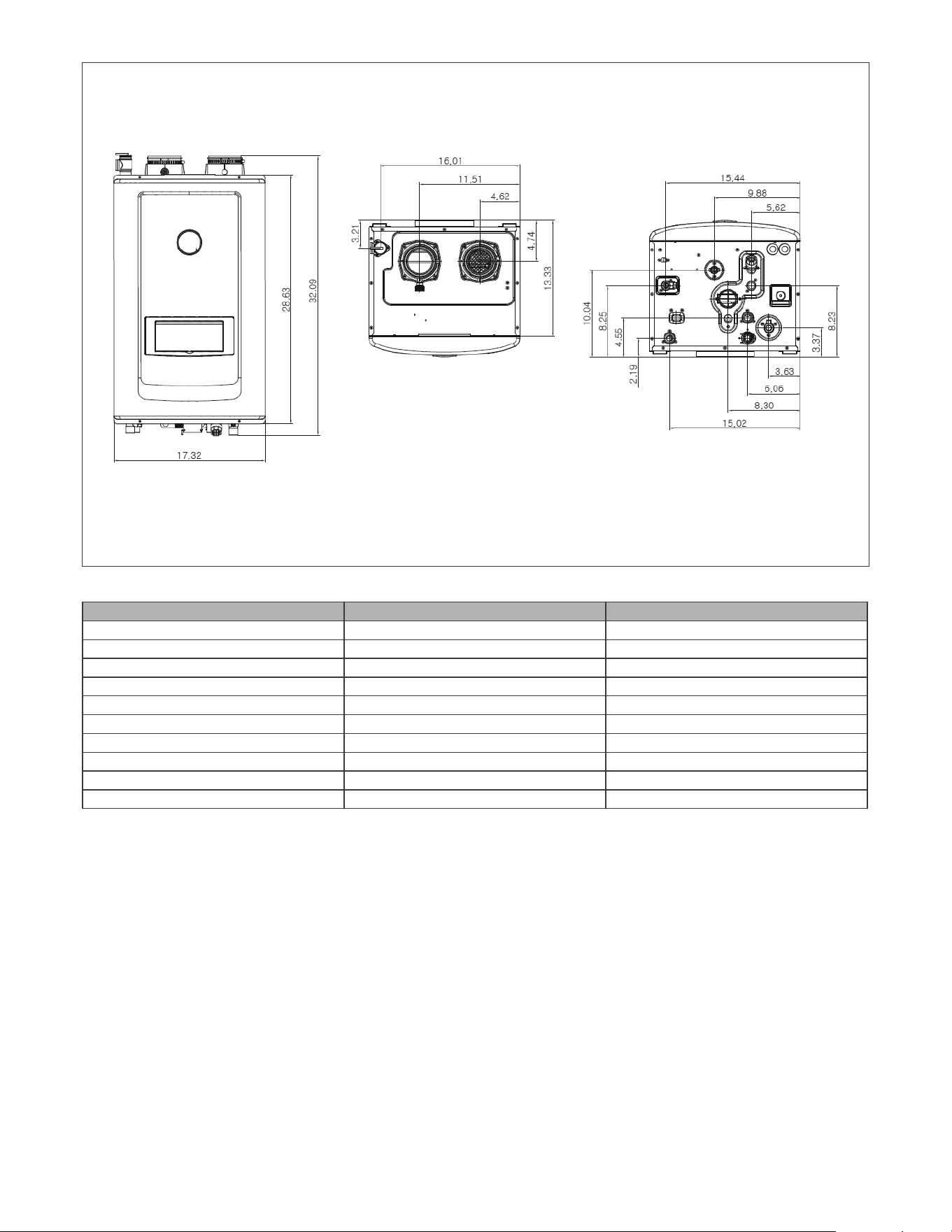
DESCRIPTION DIAMETER (ALL NPTM)
ཿ
ྀ Exhaust Vent Connection
ཱྀ Intake Pipe Connection
ྂ
ྃ
྄
྅
྆
྇ Gas Connection
ྈ Condensate Drain Connection
)LJXUH²6SHFLÀFDWLRQVDQG'LPHQVLRQV
G
ཁG
གG
གྷG
ངG
ཅG
ཆG
ཇG
G
ཉG
ཊG
7DEOH²$GDSWHU6SHFLÀFDWLRQV
13
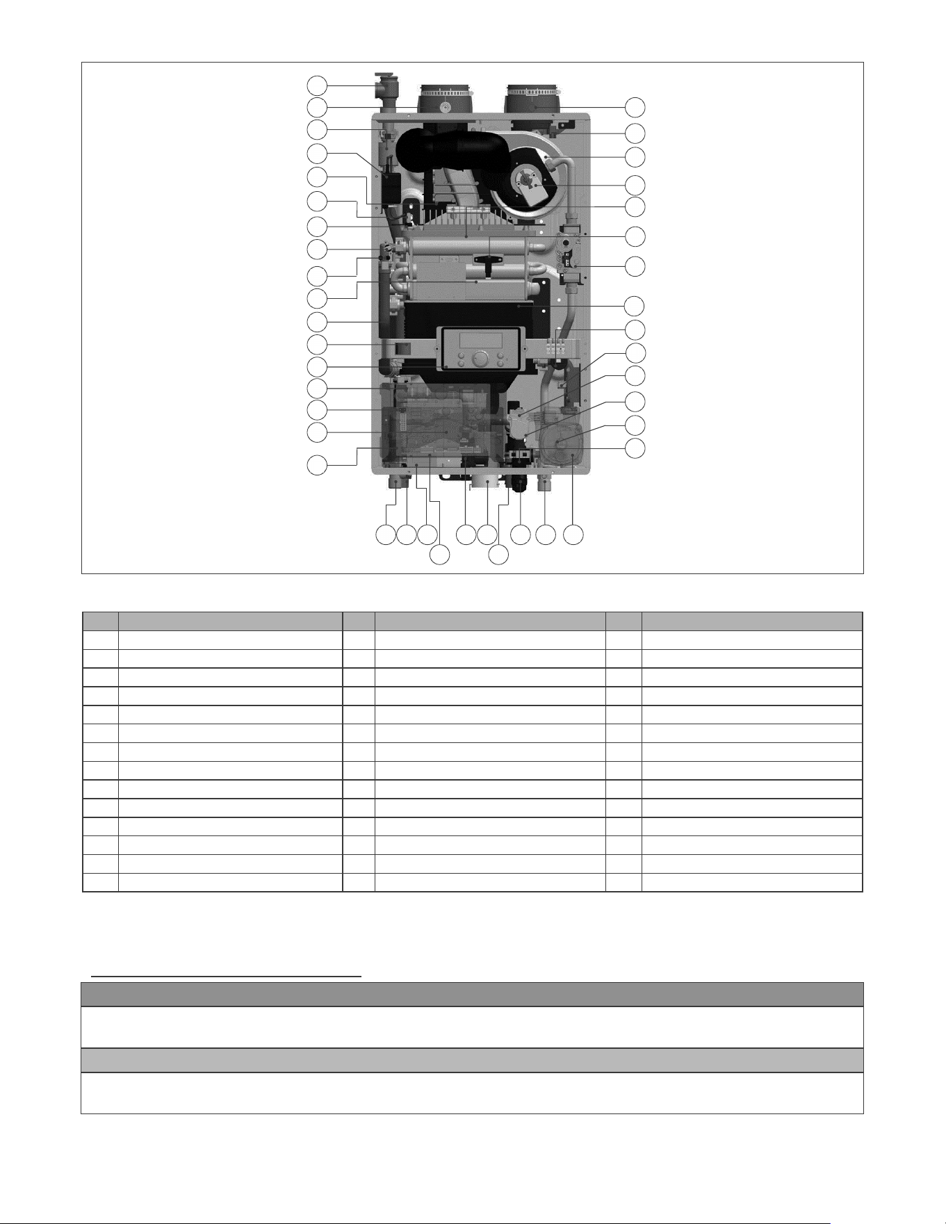
NO Name of Component NO Name of Component NO Name of Component
1 29
2 Exhaust
3 Air Vent 31
4 32 Air Pressure Switch
19 33 Pressure Sensor
34
Burner Limit Switch 21
22
9 23 Burner
24
11 39
12 Manual Power Switch Gas Connection
13 Control Panel Circulation Pump 41 Air Intake
14 Circuit Board
Figure 2 – Model Components
Table 6 – Component List
IMPORTANT
CAUTION
ƓA. UNCRATING THE APPLIANCE
UNCRATING APPLIANCE
components come to room temperature.
PART 4 –PREPARE APPLIANCE LOCATION
3DJH
ϭ
ϰ
ϳ
ϴ
ϭϭ
ϭϮ
ϭϰ
ϭϱ
ϭϲ
ϭϴ
ϭϵ
ϮϬ
Ϯϭ
ϮϮ
Ϯϯ
Ϯϰ
Ϯϱ
Ϯϲ
Ϯϳ
Ϯϴ
Ϯϵ
ϯϬ
ϯϭ
ϯϮ
ϯϰ
ϯϯ
ϯϱ
ϯϲ
ϯϳ
ϯϴ
Ϯ
ϯϵ
ϰϬ
ϰϭ
ϯ
ϱ
ϲ
ϭϳ
ϵ
ϭϬ
ϭϯ
14
WARNING
WARNING
WARNING
CAUTION
CAUTION
CAUTION
CAUTION
ƓB. BEFORE LOCATING THE APPLIANCE
personal injury, or death.
injury or death.
ㆍ
¶m¶j¶m¶j.
ㆍ
ㆍ
ㆍ
ㆍ
ㆍ
ㆍ
ㆍ
Electrical power
ㆍ
Condensate drain
ㆍ
System leaks
ㆍ
ㆍ
WARNING
WARNING
CAUTION
CAUTION
NOTE:
NOTE:
MINIMUM CLEARANCES FROM COMBUSTIBLE MATERIALS
ㆍ
ㆍ
ƓC. LEVELING
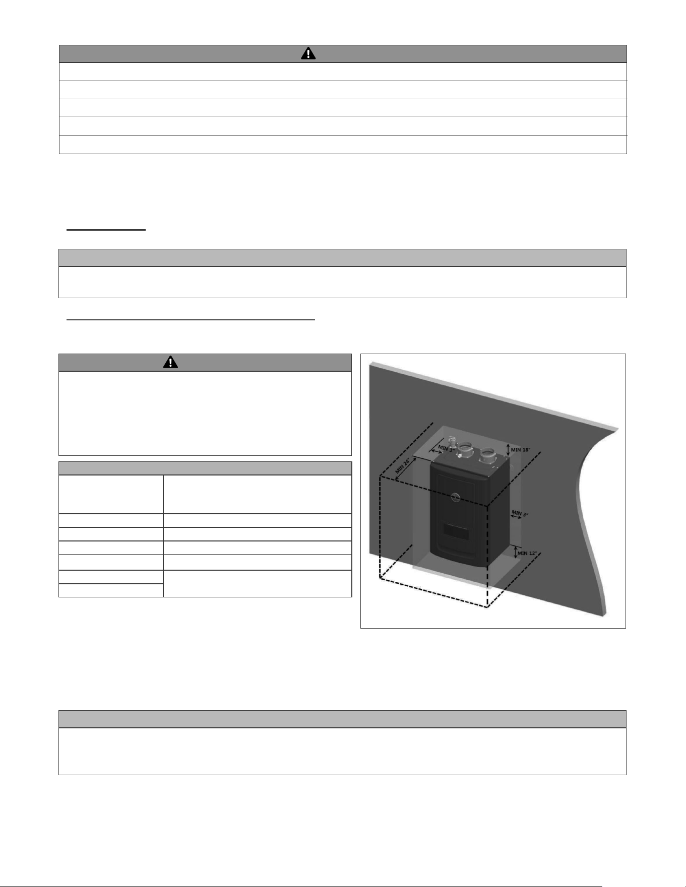
ƓD. CLEARANCES FOR SERVICE ACCESS
Figure 3 – Minimum Service Clearances
MINIMUM CLEARANCES
Installation Clearances
Clearances
Back
Bottom
Left Side
Table 7 – Minimum Installation and Service Clearances
WARNING
WARNING
WARNING
CAUTION
ƓE. RESIDENTIAL GARAGE AND CLOSET INSTALLATIONS
ƓF. EXHAUST VENT AND INTAKE PIPE
ƓG. CARBON MONOXIDE DETECTORS
appliance.
PRECAUTIONS
CAN/CSA B149 Installation Code in Canada.
ㆍ
ㆍ
In the Commonwealth of Massachusetts and As Required by State and Local Codes
whole or in part for residential purposes.
NOTE:
section.
WARNING
WARNING
ƓH. PREVENT COMBUSTION AIR CONTAMINATION
ƓI. REMOVING AN APPLIANCE FROM A COMMON VENT SYSTEM
Breathing Hazard – Carbon Monoxide Gas
Breathing carbon monoxide can cause brain damage or death. Always read and understand
instruction manual.
intake air.
NOTE: DAMAGE TO THE APPLIANCE CAUSED BY EXPOSURE TO CORROSIVE VAPORS IS NOT COVERED BY WARRANTY.
PRODUCTS TO AVOID AREAS LIKELY TO HAVE CONTAMINANTS
Chlorinated waxes/cleaners
Beauty shops
Table 8 – Products and Areas Likely to Have Contaminants
ㆍ
ㆍ
ㆍ
ㆍ
ㆍ
ㆍ
ㆍ
DANGER
DANGER
Figure 4 – CO Warning Label
3DJH
When removing an existing heater, follow the steps below.
that could cause an unsafe condition.
WARNING
WARNING
WARNING
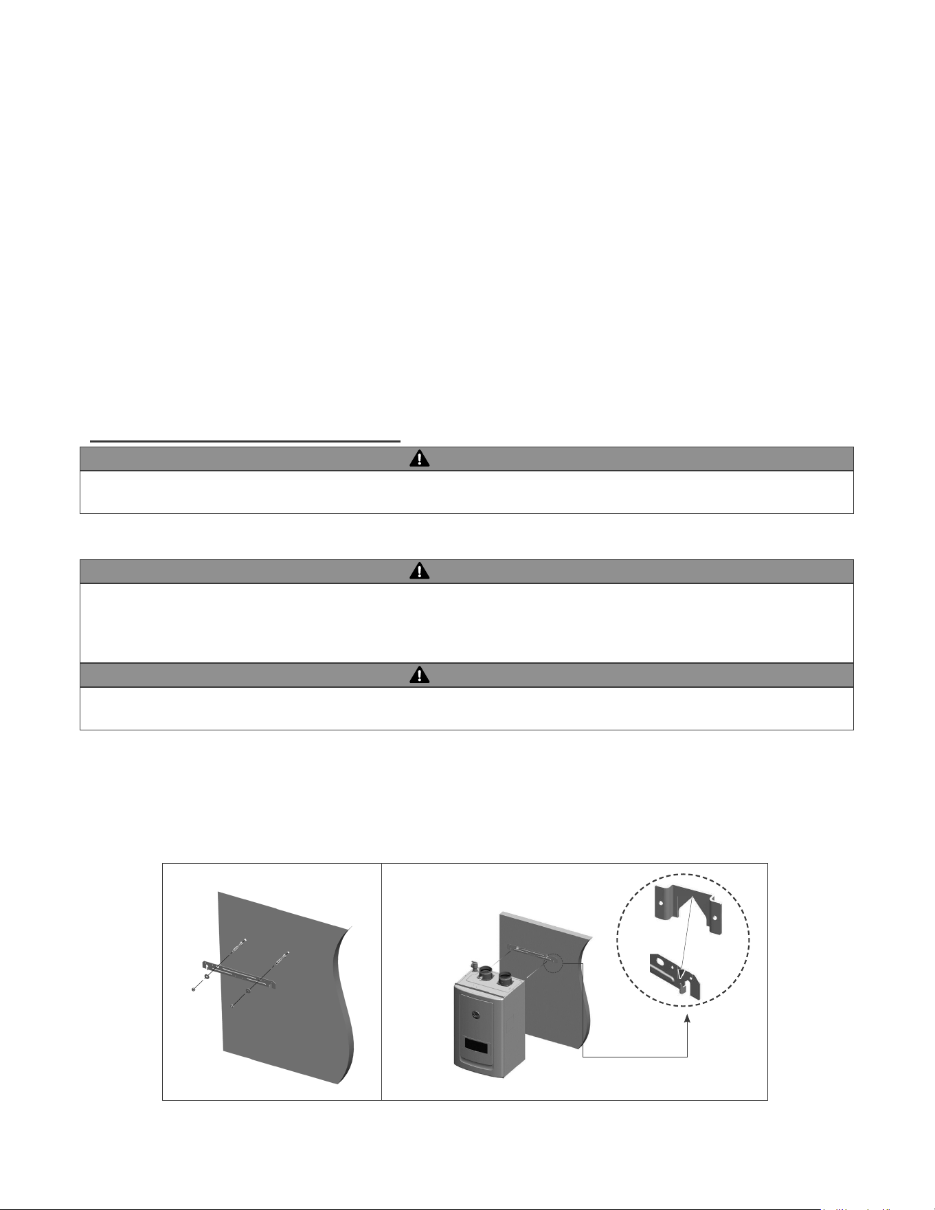
ƓJ. WALL-MOUNTING THE APPLIANCE
POSITIONING THE APPLIANCE ON THE WALL
A B
Figure 5 – Wall Mounting the Appliance
19
and/or CSA B149.1, Natural Gas and Propane Installation Code.
ƓA. INTAKE PIPE AND EXHAUST VENT GUIDELINES
WARNING
¼
drains properly.
PART 5 –VENTING
DANGER
In addition:
In the Commonwealth of Massachusetts and as Required by State and Local Codes:
WARNING
21
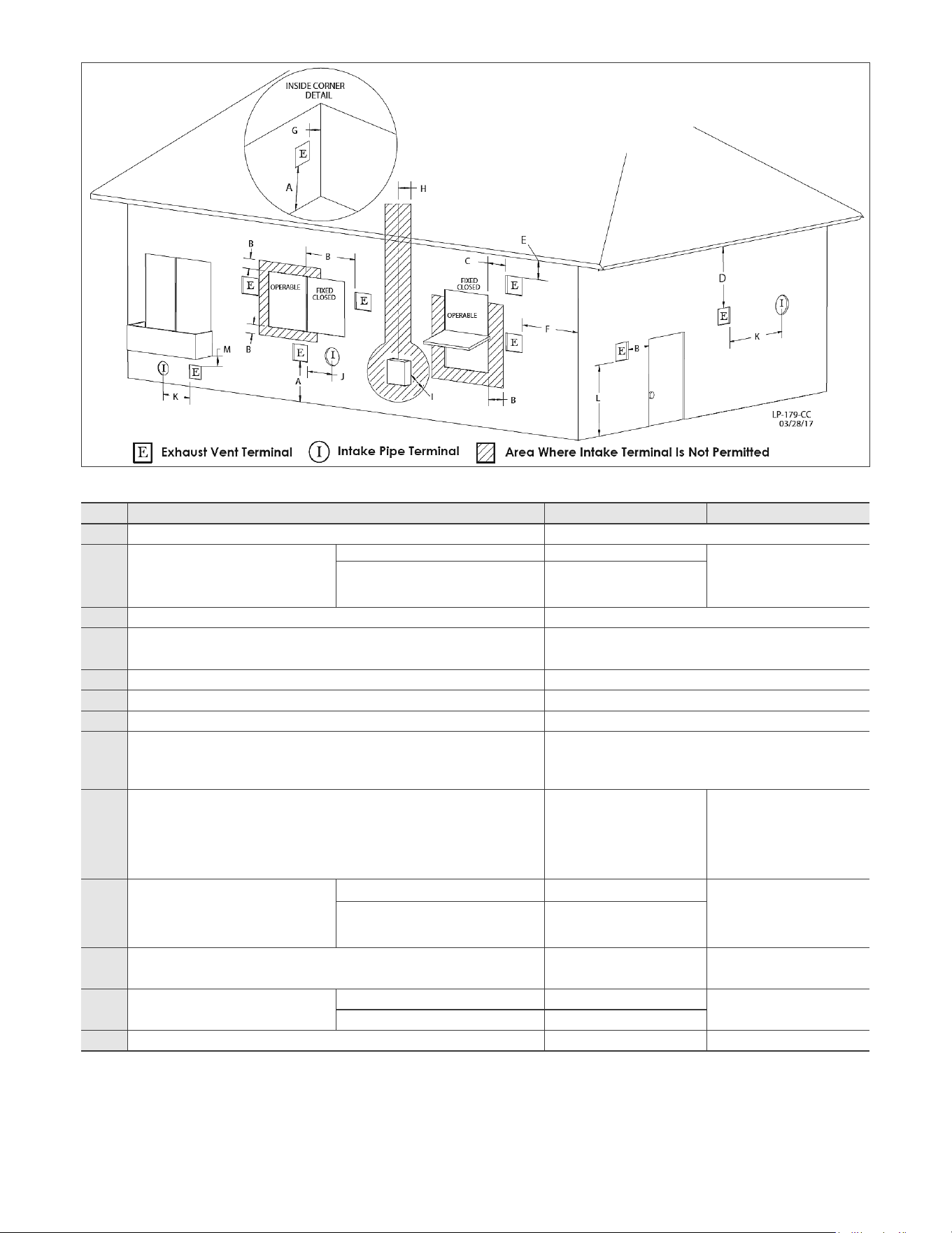
Figure 6 – Vent Termination Detail
Table 9 – Vent Termination Clearances
NOTE:
DESCRIPTION US CANADA
A
B
Clearance to window or door that may
Direct Vent 1 foot
Power Vent
-
C
Clearance to permanently closed window *
D
-
*
E
*
F
Clearance to outside corner *
G
Clearance to inside corner *
H
-
*
I
*
J
Clearance to non-mechanical air sup-
air inlet to any other appliance
Direct Vent 1 foot
Power Vent
-
K
Clearance to a mechanical air supply inlet
L
Direct Vent *
Power Vent
M
*
22
ƓB. APPROVED VENT MATERIALS
ƓC. ALLOWED COMBINED VENT LENGTHS
WARNING
DANGER
NOTICE
APPROVED EXHAUST VENT AND INTAKE PIPE MATERIAL
Item Material
Standards for Installation in:
United States Canada
Exhaust vent
or Intake pipe
DQGÀWWLQJV
Polypropylene
Stainless Steel
AL29-4C
Pipe Cement
PVC
CPVC
Pipe Primer PVC / CPVC
MINIMUM MAXIMUM MINIMUM MAXIMUM MINIMUM MAXIMUM MINIMUM MAXIMUM
Table 10 – Approved Venting Materials
Table 11 – Approved Vent Lengths
CAUTION
¶m¶j
23
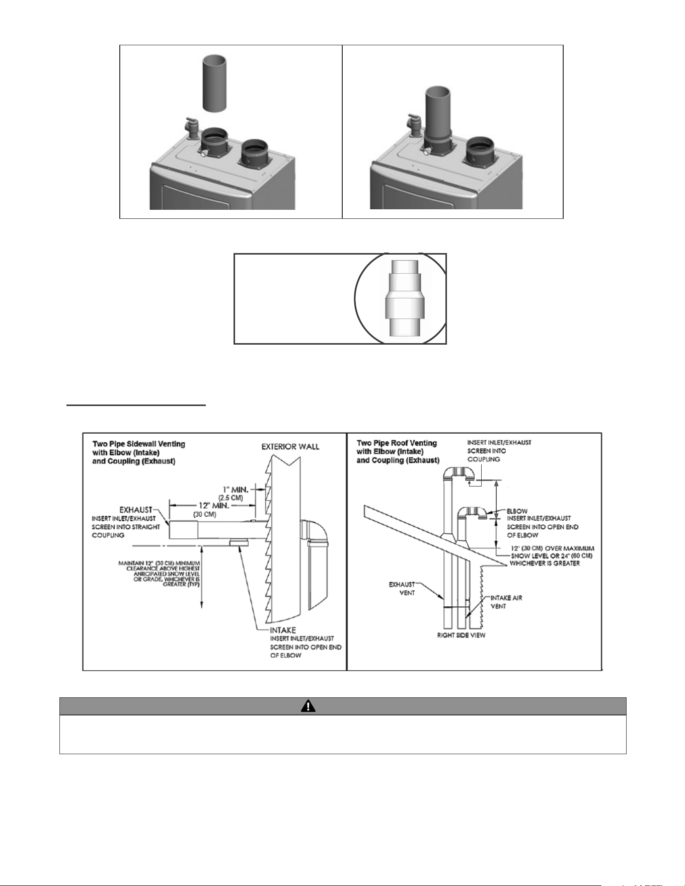
ƓD. TIGHTENING APPLIANCE COLLAR TO EXHAUST VENT AND INTAKE PIPE
WARNING
CAUTION
CAUTION
NOTE:
PVC Venting
CPVC or Polypropylene(PP) Venting
details.
24
NOTE: REDUCING VENT SIZE;
TRANSITIONING FROM 3” TO
2” VENT PIPE MUST ALWAYS
TAKE PLACE IN A VERTICAL
POSITION TO PREVENT
CONDENSATE BLOCKAGE
Figure 7 – Installing the 3" Pipe into the Exhaust Vent Connection
Figure 9 – Direct Vent, Roof and Sidewall Vent Terminations
Figure 8 – Transitioning from 3" to 2" Vent Pipe
ƓE. VENT TERMINATION
WARNING
ELBOW
12 Min (30cm)
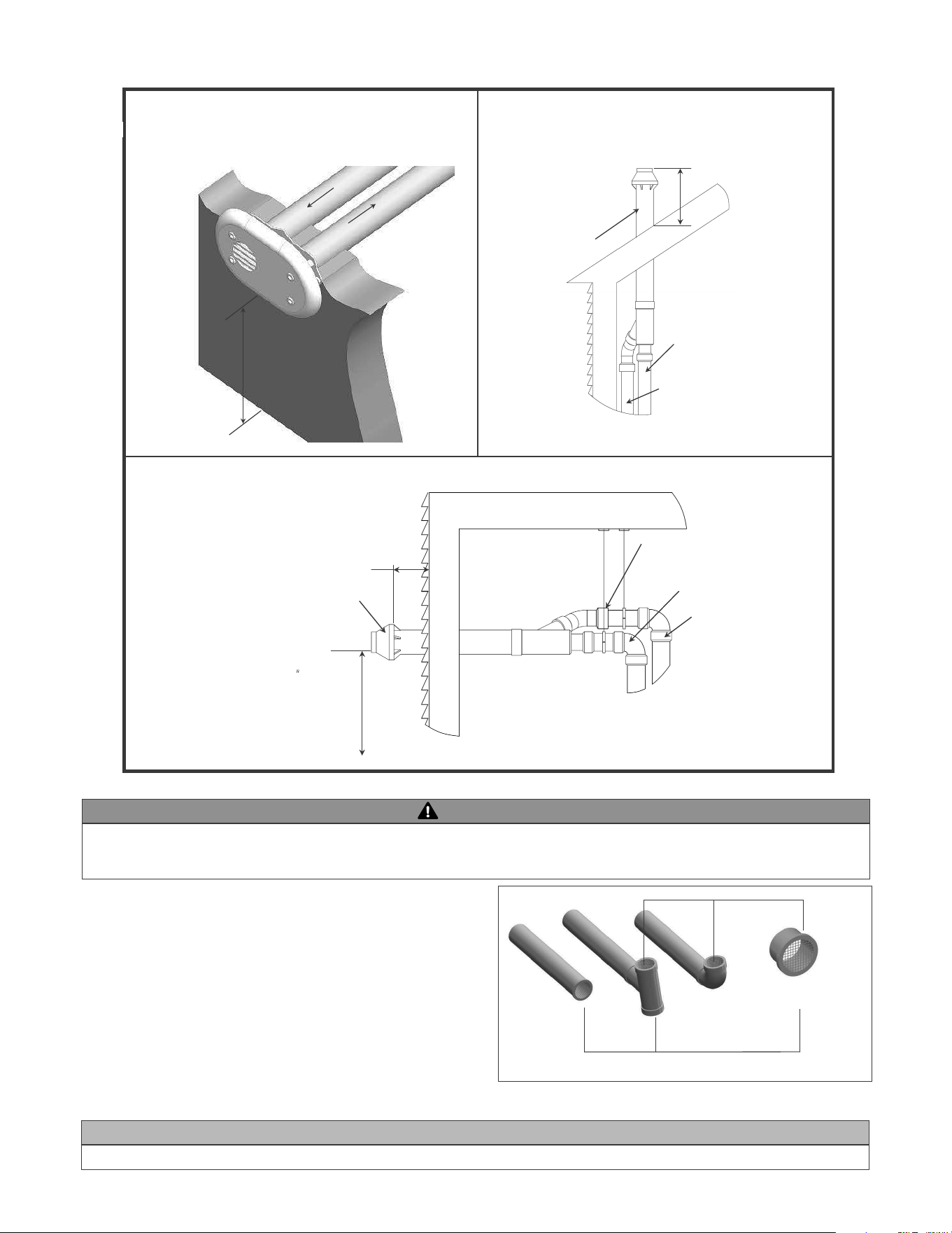
Figure 10 – Direct Vent, Vent Terminations (with Optional Kits)
Figure 11 – Screen Installation
WARNING
3. Screen Installation
3”(7.6cm) Vent Screen
1/4”(0.6cm) Mesh
Two screens of 2 “and 3” are provided. Please purchase and install additional screens if
necessary.
SAFETY INSTRUCTIONS
Exhaust
Air Inlet
Min. 12 ”
above grade
or snow level
Exhaust
Air - inlet around
Perimeter
Sidewall Venting with Kit
G
EXHAUST
INTAKE
Sidewall Venting
with Concentric Vent
Kit
MAINTAIN 12” MINIMUM
CLEARANCE ABOVE
HIGHEST ANTICIPATED
SNOW LEVEL OR GRADE,
CONCENTRIC VENT KIT
1” MIN.
IMPORTANT:
INTAKE LEG MUST
BE FACING UP
EXHAUST
INTAKE
Roof Venting
w
ith Concentric Vent
K
it
12” OVER MAXIMUM SNOW
LEVEL OR 24
” - WHICHEVER
IS GREATER
CO
NCENTRIC VENT KIT
NOTE: EXTEND VENT RUNS WHEN
TRANSITIONING TO A LARGER
DIAMETER MUST ALWAYS TAKE
PLACE IN A VERTICAL POSITION
Sidewall Venting with
Concentric Vent Kit
Roof Venting
Concentric Vent
Kit
Sidewall Venting
with Kit
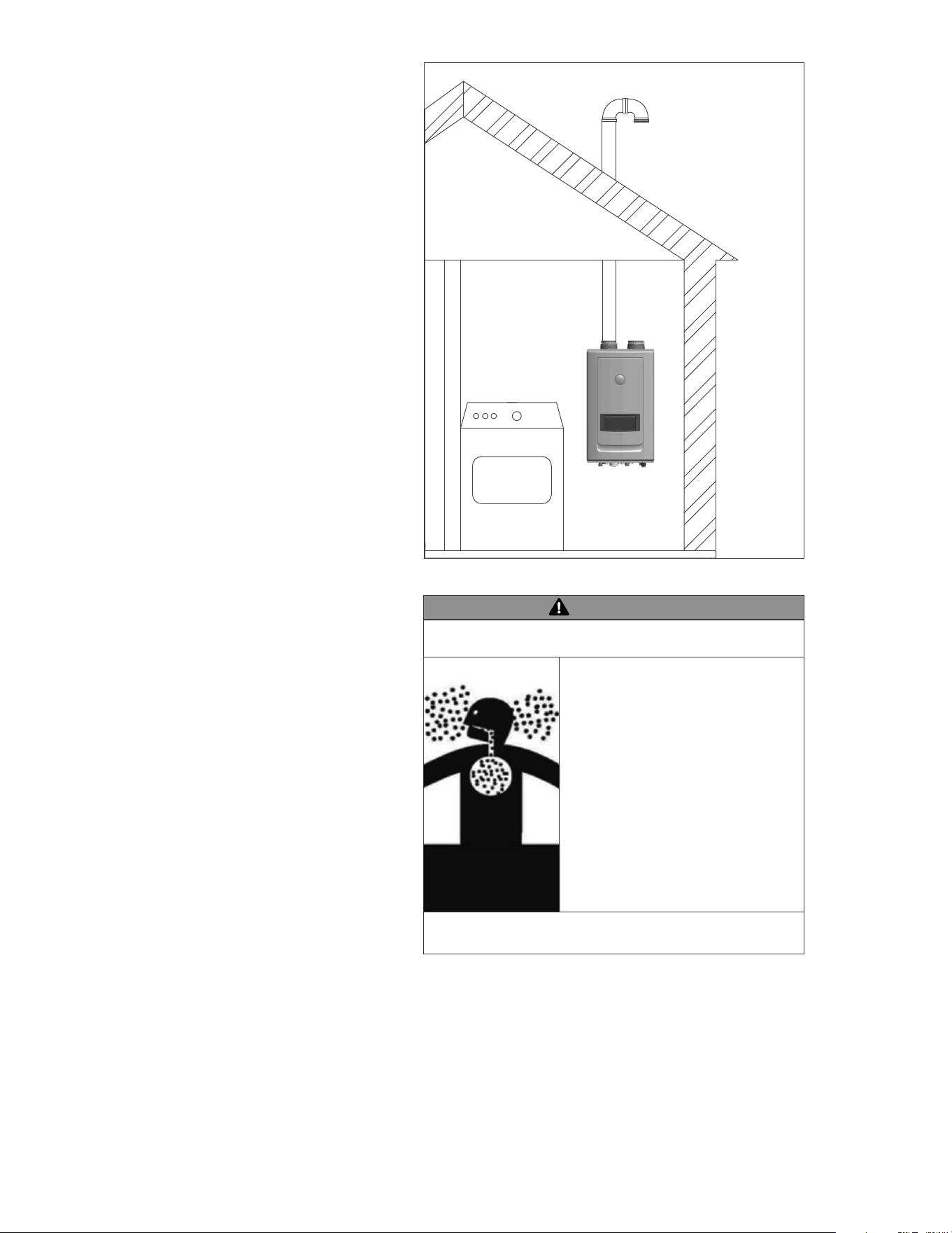
DO NOT PLACE
DRYER IN PROXIMITY
TO WATER HEATER
Figure 12 – Do Not Install in a Contaminated Space
to the heater. If the heater is installed in areas where indoor
is taken directly from the outdoors into the heater intake
connection.
space.
space.
༆
༆
WARNING
Breathing Hazard – Carbon Monoxide Gas
Breathing carbon monoxide can cause brain damage or death.
Always read and understand instruction manual.
ㆍ
ㆍ
and manufacturers installation instructions.
ㆍ
installation instructions.
ㆍ
near unit.
ㆍ
area.
ㆍ
outdoors.
ㆍ
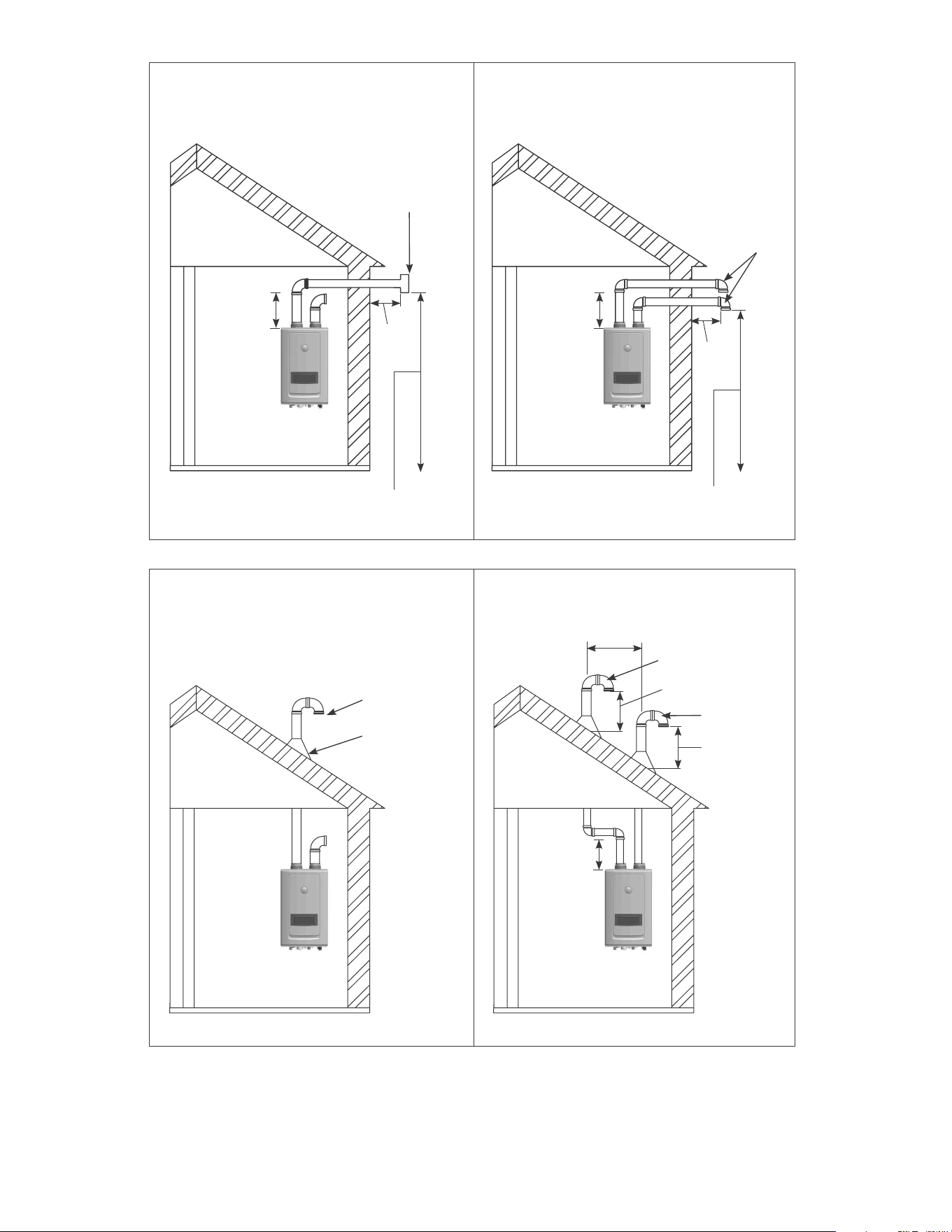
Figure 13 – NOTE: These drawings are meant to demonstrate system venting only. The installer is responsible for
all equipment and detailing required by local codes.
INDOOR COMBUSTION AIR
(SINGLE PIPE) _HORIZONTAL
INDOOR COMBUSTION AIR
(DIRECT VENT) _HORIZONTAL
INDOOR COMBUSTION AIR
(DIRECT VENT) _VERTICAL
INDOOR COMBUSTION AIR
(SINGLE PIPE)_VERTICAL
ǰFP
3ft. Min.
ǰFP
ǰFP
INSERT SCREEN IN
EACH OPEN END
OF TEE
INSERT SCREEN IN
OPEN END OF ELBOW
INSERT SCREEN IN
OPEN END OF ELBOW
INSERT SCREEN IN
OPEN END OF ELBOW
12” over maxium snow level or
24” whichever is greater.
12” over maxium
snow level or 24”
whichever is greater.
ROOF FLASHING
INSERT SCREEN IN OPEN
END OF EACH ELBOW
3"Min
(7.5cm)
3"Min
(7.5cm)
MAINTAIN 12"(30cm) MINIMUM CLEARANCE
ABOVE HIGHEST ANTICIPATED SNOW LEVEL
OR GRADE, WHICHEVER IS GREATER.
MAINTAIN 12"(30cm) MINIMUM CLEARANCE
ABOVE HIGHEST ANTICIPATED SNOW LEVEL
OR GRADE, WHICHEVER IS GREATER.
cement.
for depletion.
deterioration.
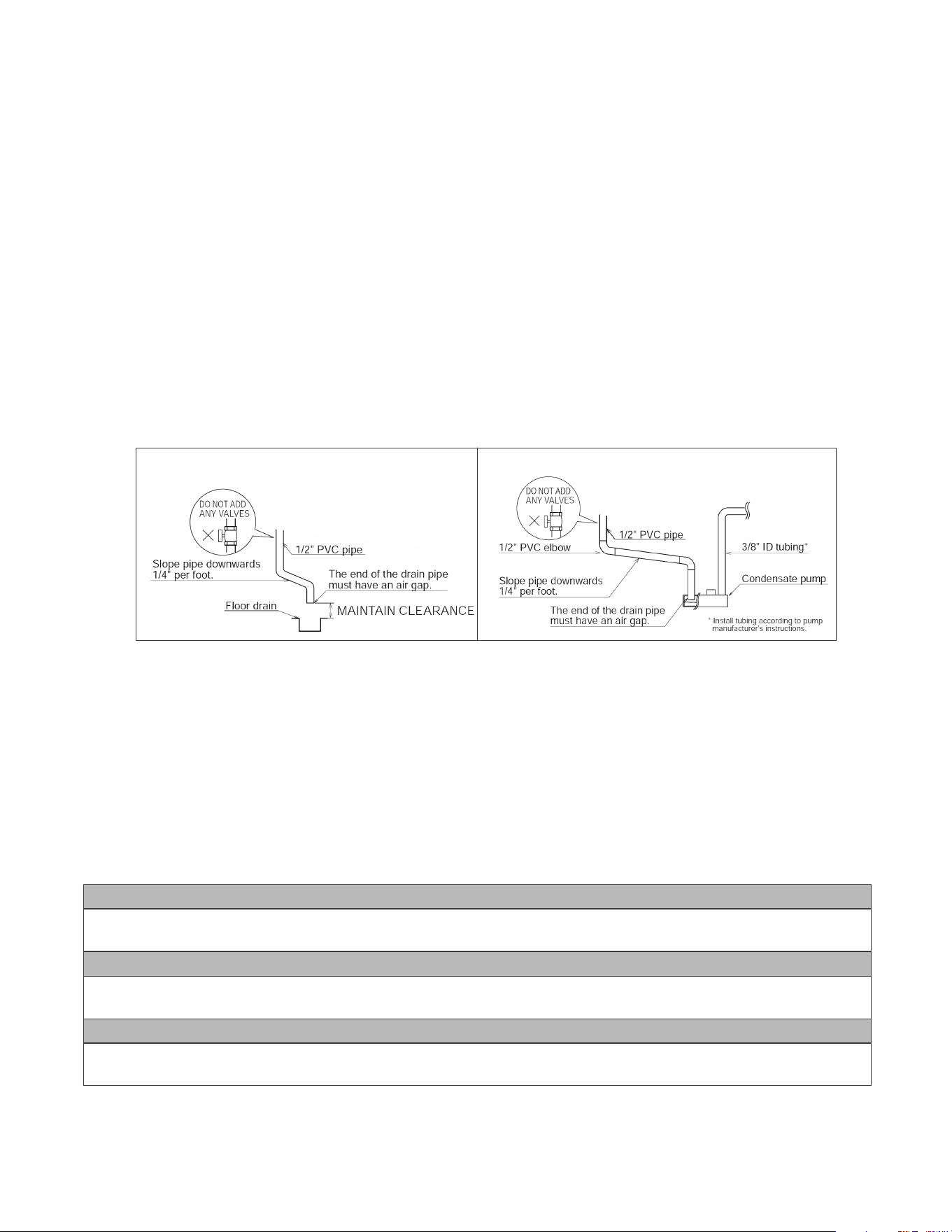
PART 6 – INSTALL THE CONDENSATE DRAIN
NOTE:
NOTE:
NOTES:
&RQGHQVDWHSLSLQJWRÁRRUGUDLQ
Condensate piping with pump
Figure 14 – Condensate Piping to Floor Drain and with Pump
CAUTION
CAUTION
CAUTION
29
PART 7 – GAS PIPING
WARNING
1. Gas Pipe Sizing
3
3
ƓA. GAS PIPE SIZING TABLES
Pipe
199 92
424
Pipe
312 214 131
949 331 242
1392 1191
1919
4433
9314
11139
Table 13. For 8" WC ~ 10.5" WC initial supply pressure
Table 12. For Less than 8" WC initial supply pressure
Table 14. Maximum Undiluted Propane (LP) Delivery Capacity in Thousands of Btu/H (0.5" WC Pressure Drop)
Pipe
291 122 94
231 212 129
434 349 292 243
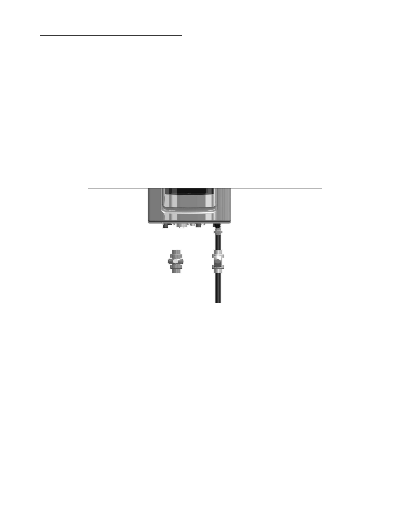
Figure 15 – Gas Line with Shut-Off Valve Detail
NOTE:
same time.
ƓB. GAS CONNECTION REQUIREMENTS
GAS VALVE OFF
GAS VALVE ON
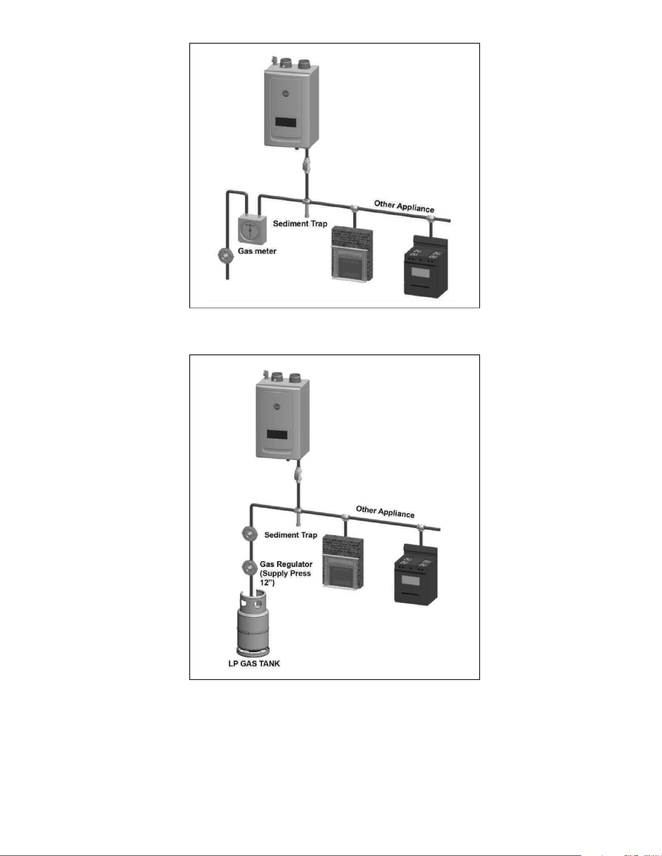
31
Figure 16 – Natural Gas Piping Installation
Figure 17 – LP Gas Piping Installation
NOTE:
NOTE:
32
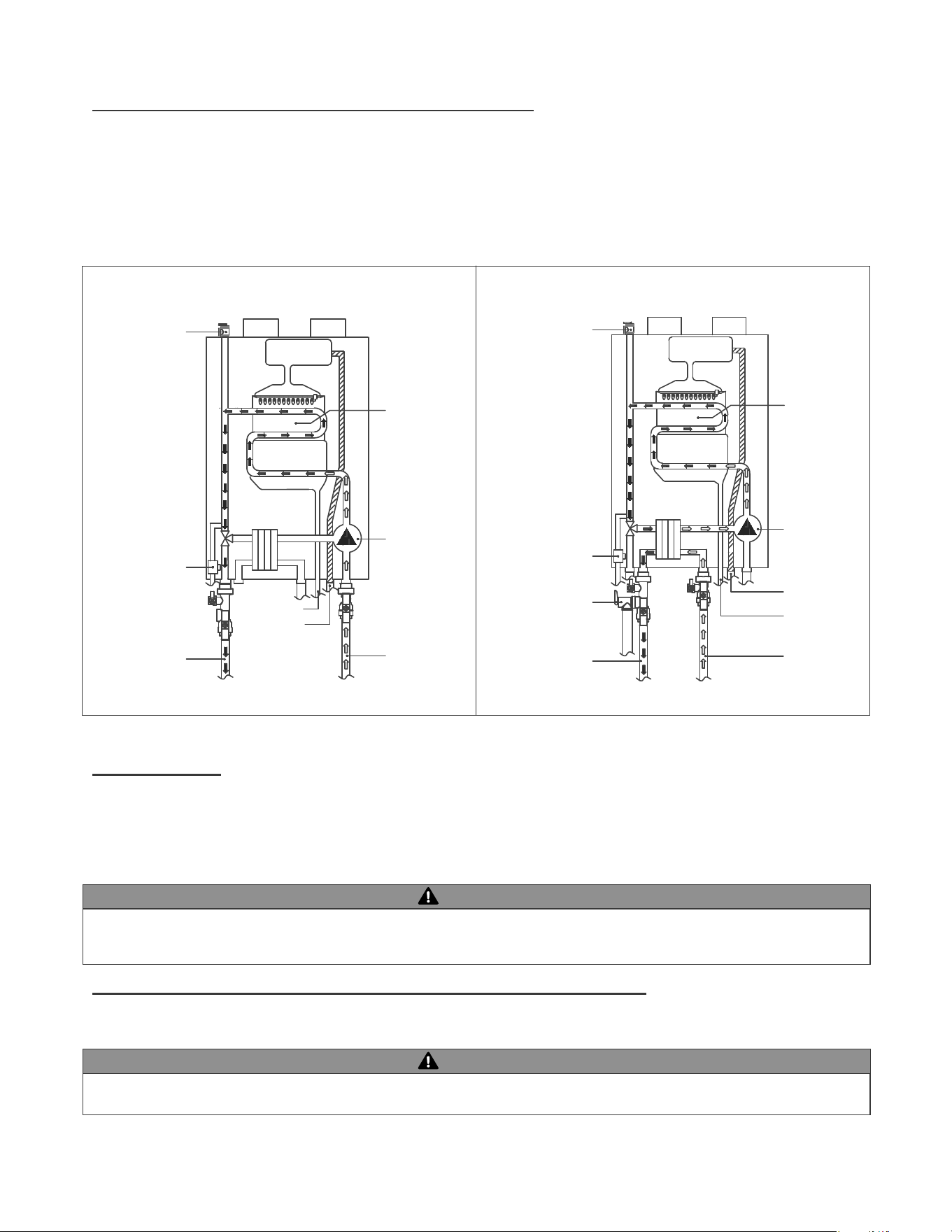
Burner
Air & Gas
Mixing
Primary Heat
Exchanger
Secondary Heat
Exchanger
Circulation Pump
Gas
Condensate
Heating Supply
Heating Return
Pressure Relief Valve
for Heating
Auto Feeder
DHW
Plate
Heat
Exchanger
Burner
Air & Gas
Mixing
DHW
Plate
Heat
Exchanger
Primary Heat
Exchanger
Secondary Heat
Exchanger
Gas
Condensate
Cold Water Inlet
(DHW)
Hot Water Outlet
(DHW)
Pressure Relief Valve
(DHW)
Pressure Relief Valve
for Heating
Circulation Pump
Auto Feeder
PART 8 – WATER PIPING
[Space Heating Mode] [Domestic Hot Water Mode]
ƓA. GENERAL PLUMBING CONNECTION GUIDELINES
Figure 18 – Operating Description – Water Flow
ƓB. DHW PIPING
ƓC. CENTRAL HEATING PIPING SYSTEM WATER PIPING METHODS
EXPANSION TANK AND MAKE-UP WATER
WARNING
WARNING
33
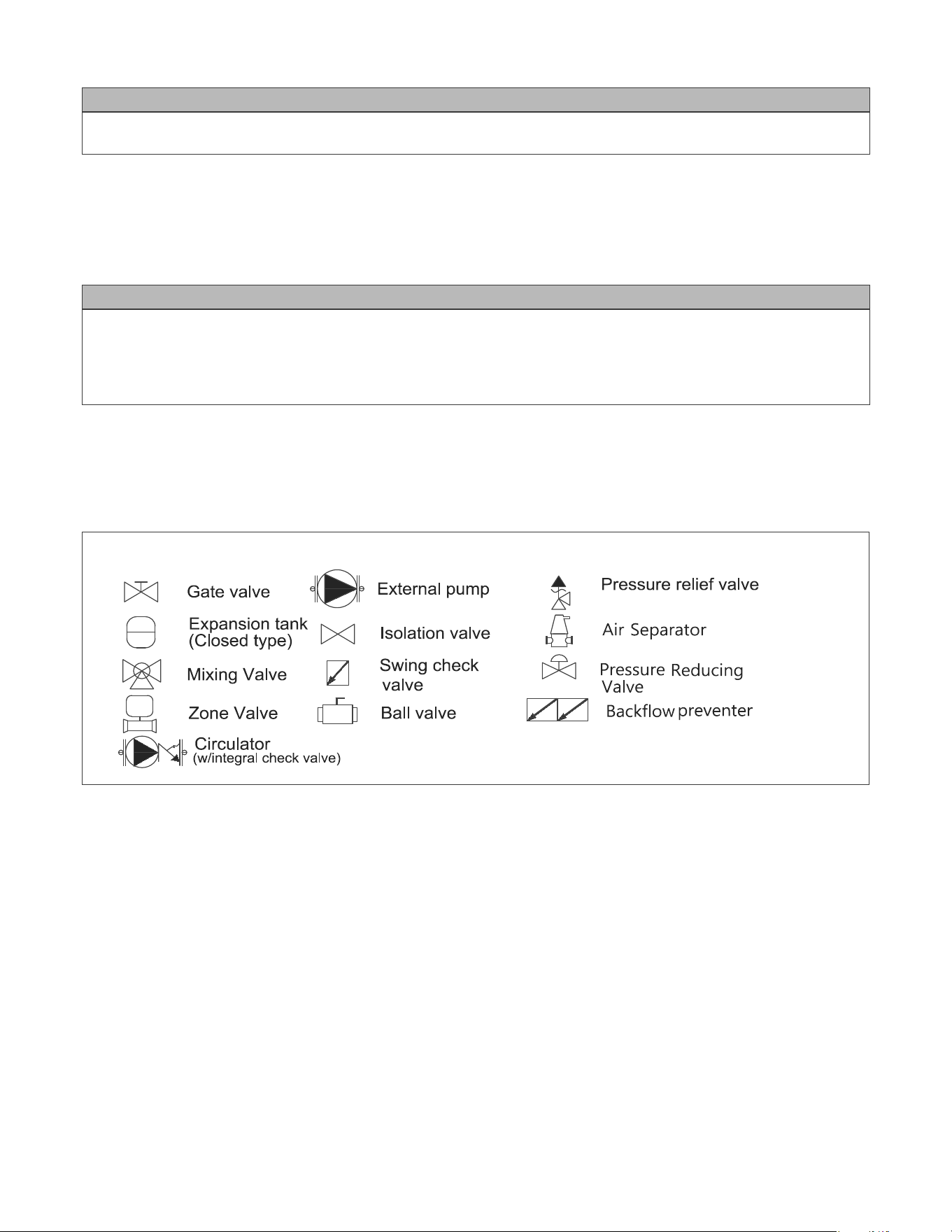
Piping symbol legend
Figure 19 – Piping Legend
the appliance to operate when there is a call for heat.
DIAPHRAGM (OR BLADDER) EXPANSION TANK
connection at the same point as the expansion tank connection to the system.
CAUTION
CAUTION
SUCH FAILURE IS NOT COVERED BY WARRANTY.
34
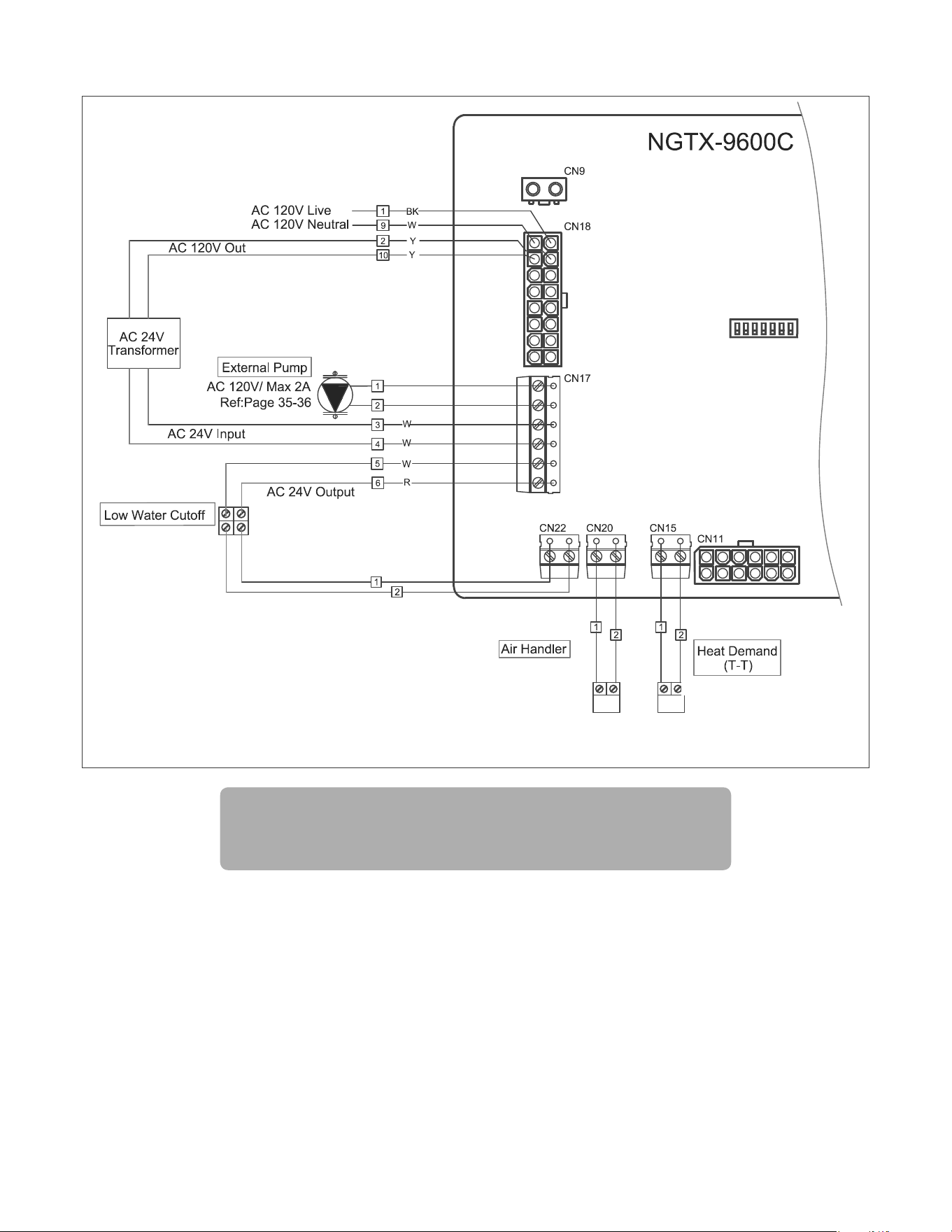
Note:
Ref: Page 37
Ref: Page 36
Wiring diagram for External Options
NOTES:
VERY IMPORTANT –
factory default.
11. NOTE:
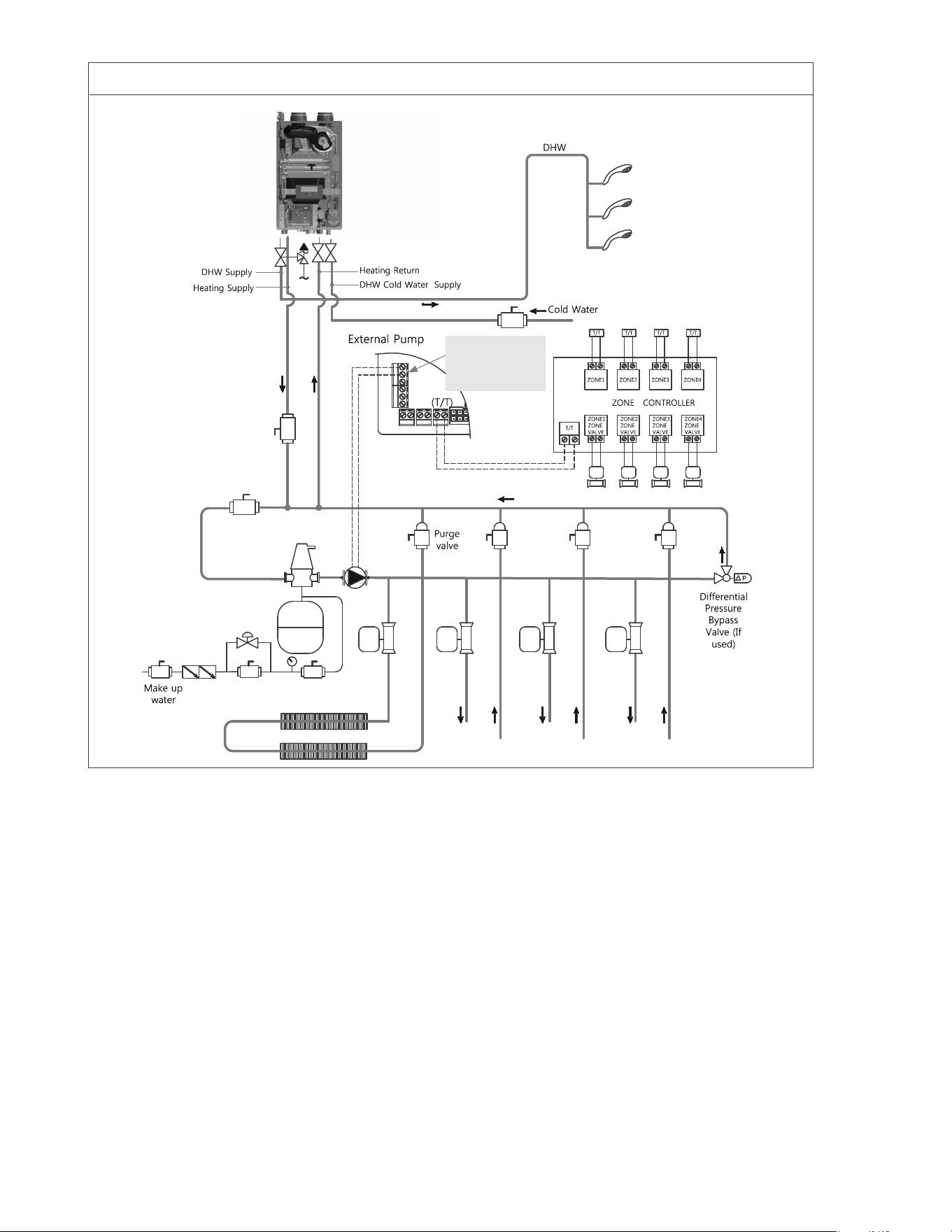
Figure 20 – CH and DHW Piping
Primary / Secondary Piping with Zone Valves DHW Priority.
NOTES:
VERY IMPORTANT –
factory default.
11. NOTE:
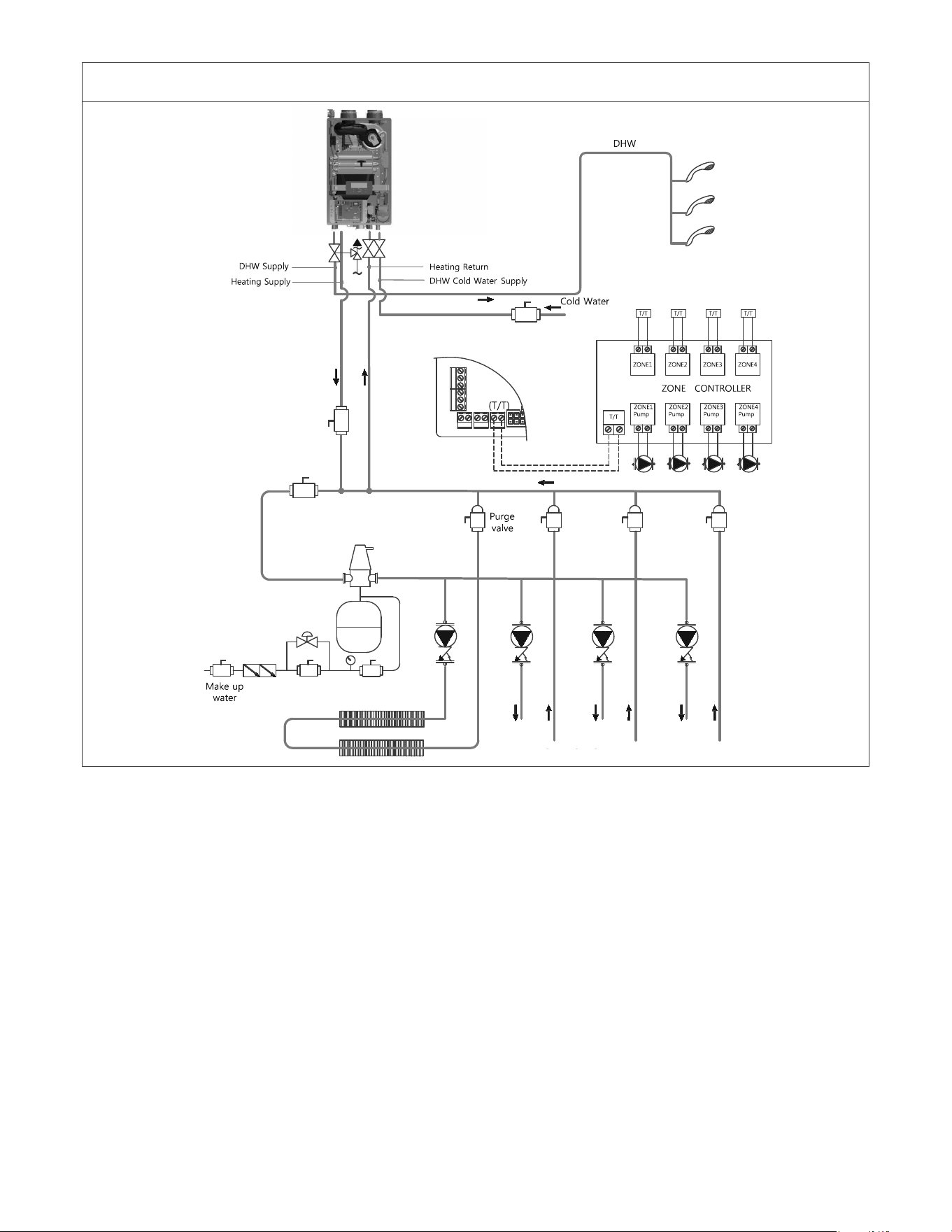
Figure 21 – CH Piping – Zoning with Pumps
Primary / Secondary Piping with Zone Pumps DHW Priority. (Outdoor Reset)
NOTES:
ㆍ
ㆍ
ㆍ
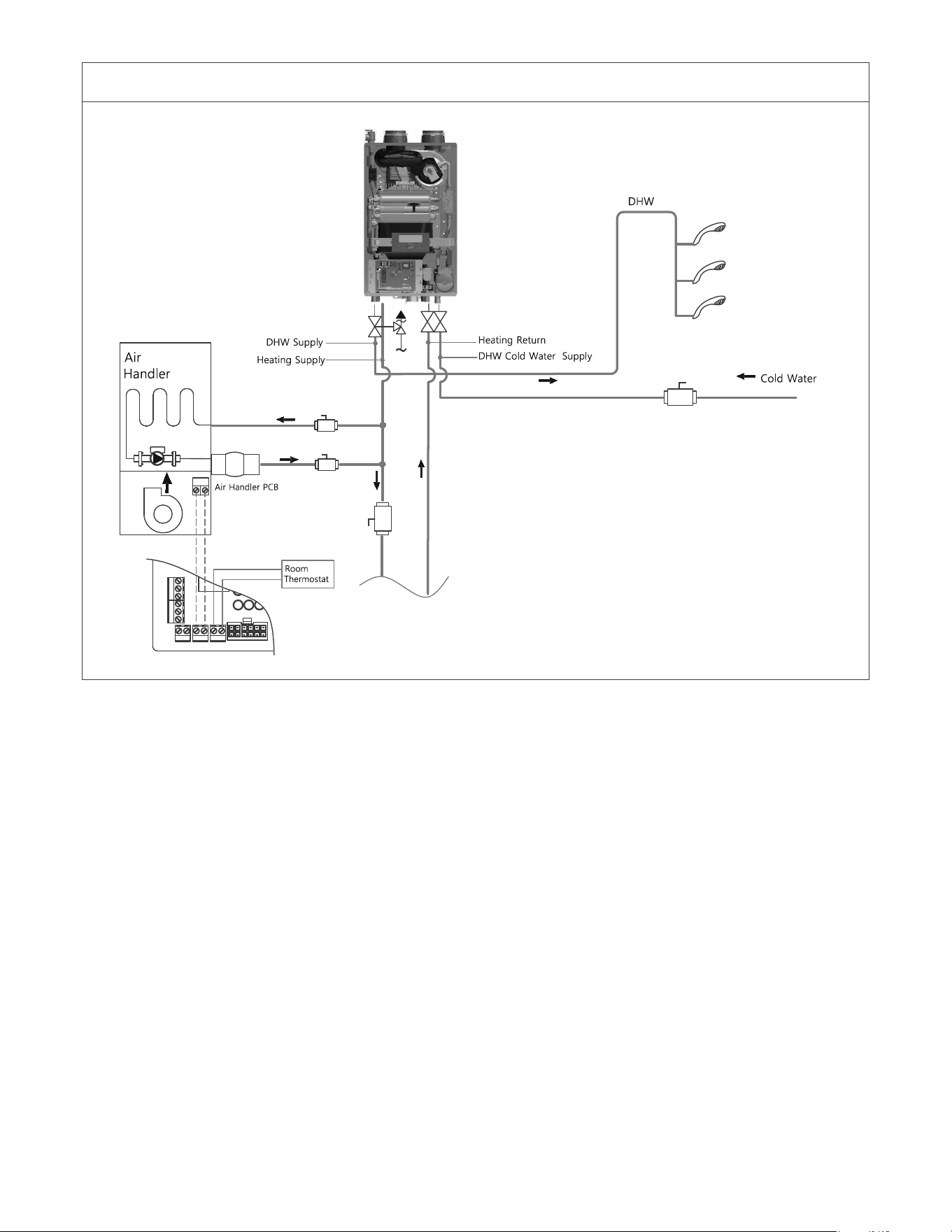
Figure 22 – CH Piping with Air Handler
Air Handler Piping.
ƓD. CH AND DHW PRESSURE RELIEF VALVES
plate on the appliance.
CH Loop
DHW Loop
WARNING
WARNING
immediately.
FAILURE TO COMPLY WITH THE ABOVE GUIDELINES COULD RESULT IN FAILURE OF RELIEF VALVE OPERATION, RESULTING IN
POSSIBILITY OF SUBSTANTIAL PROPERTY DAMAGE, SEVERE PERSONAL INJURY, OR DEATH.
personal injury, or death.
PART 9 – CONNECT ELECTRICAL POWER / INITIAL STARTUP
39
WARNING
WARNING
ƓA. GENERAL OPERATING CONDITIONS
ƓB. WIRING INFORMATION
ƓC. DIP SWITCHES
¶m¶j
¶m¶j
4. Do not disconnect the power supply when the appliance is in normal operation.
NOTE:
warranty.
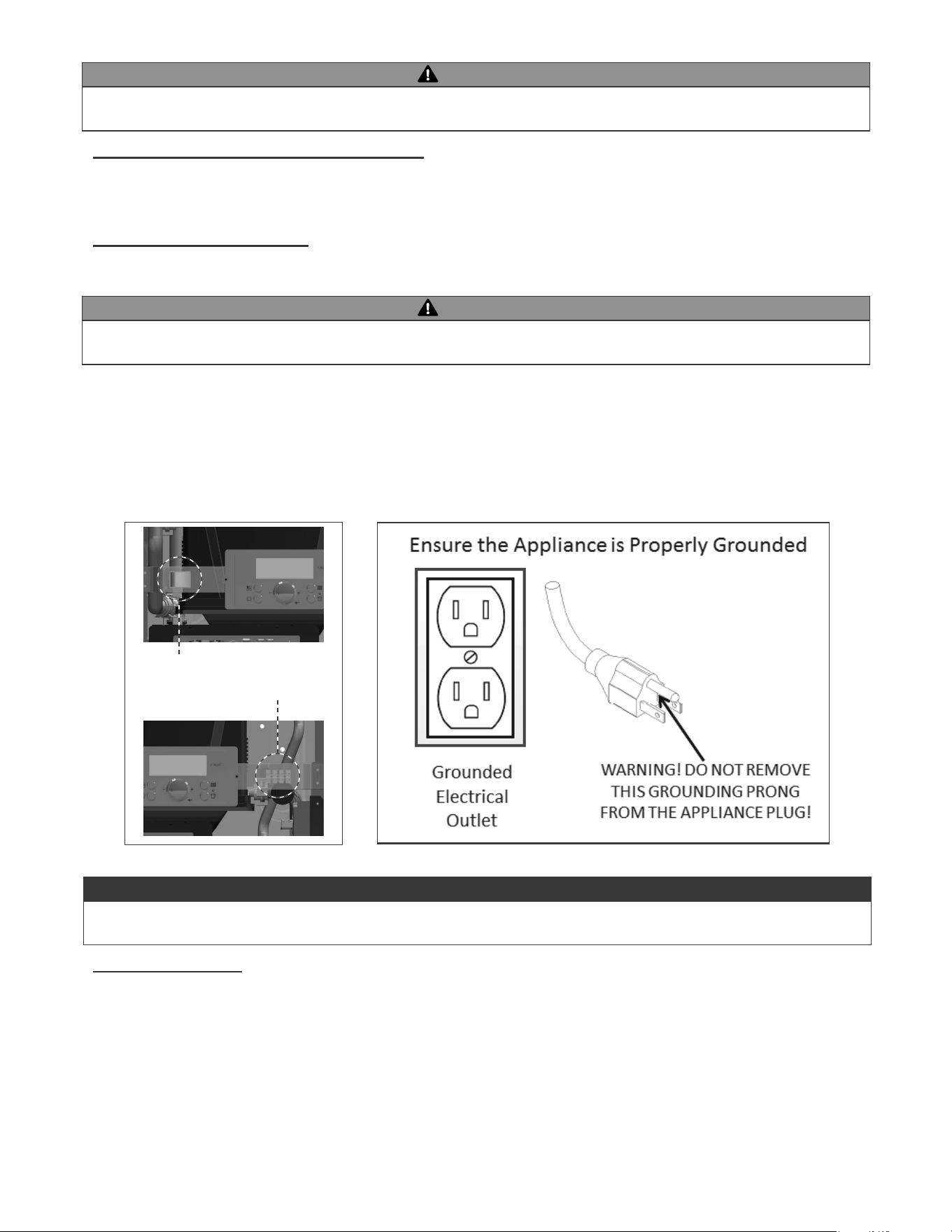
Figure 23 – Manual Power Switch and Appliance Plug Details
NOTICE
Manual Switch
Terminal Block
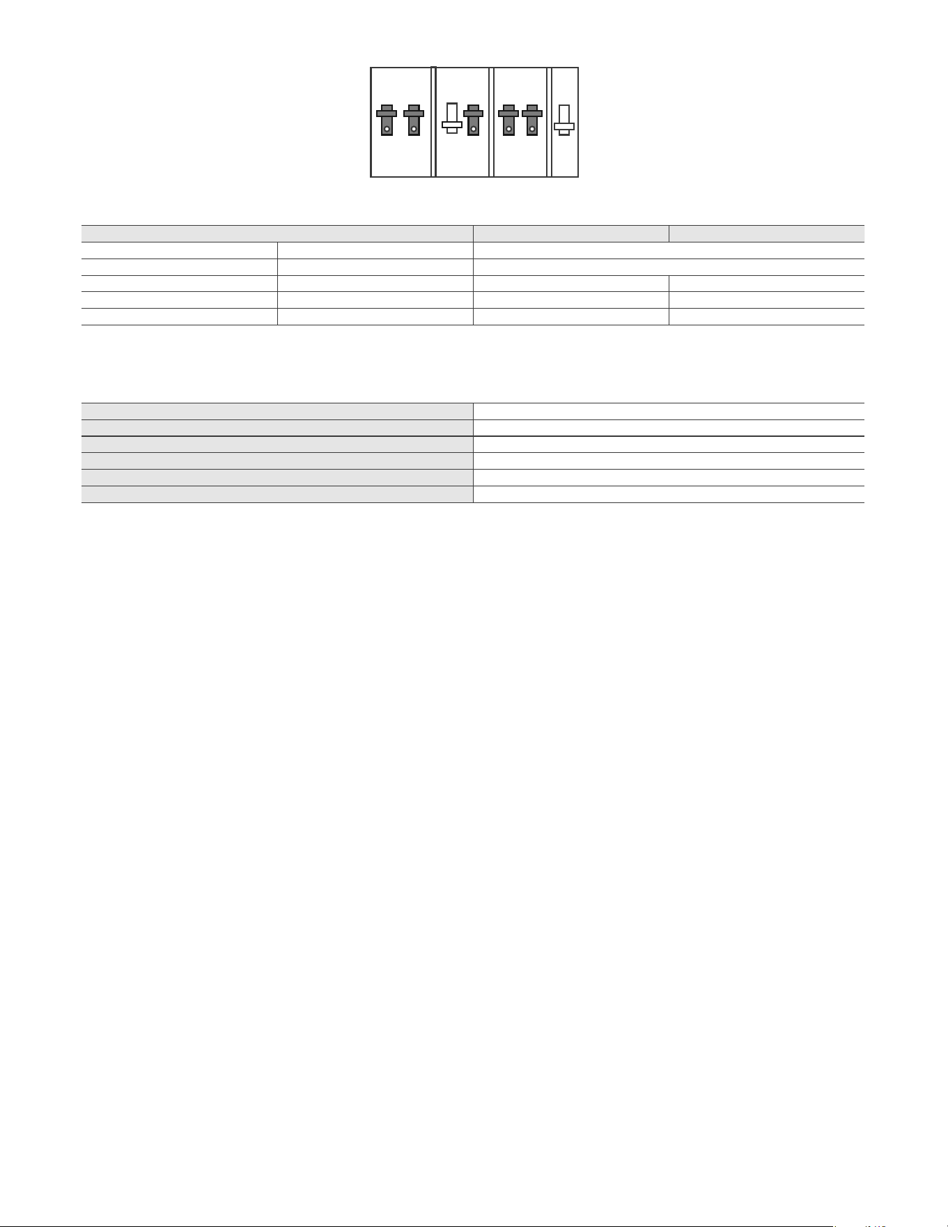
Figure 24 – Dip Switch Detail
Table 15 – Dip Switch Detail
Table 16 – System Control Settings
12345
ON
67
DIP SWITCH OFF ON
1 – 3
4
LP NG
Normal
Normal
MAXIMUM FLAME DETECTING VOLTAGE
PRE-PURGE TIME (Tp)
SAFETY TIME (IGNITING TIME) (Ts) 2 seconds
IGNITING INTERVAL TIME 2 seconds
POST-PURGE TIME (Tip)
OVER-HEATING PROTECTION DETECTION TIME <3 seconds
41
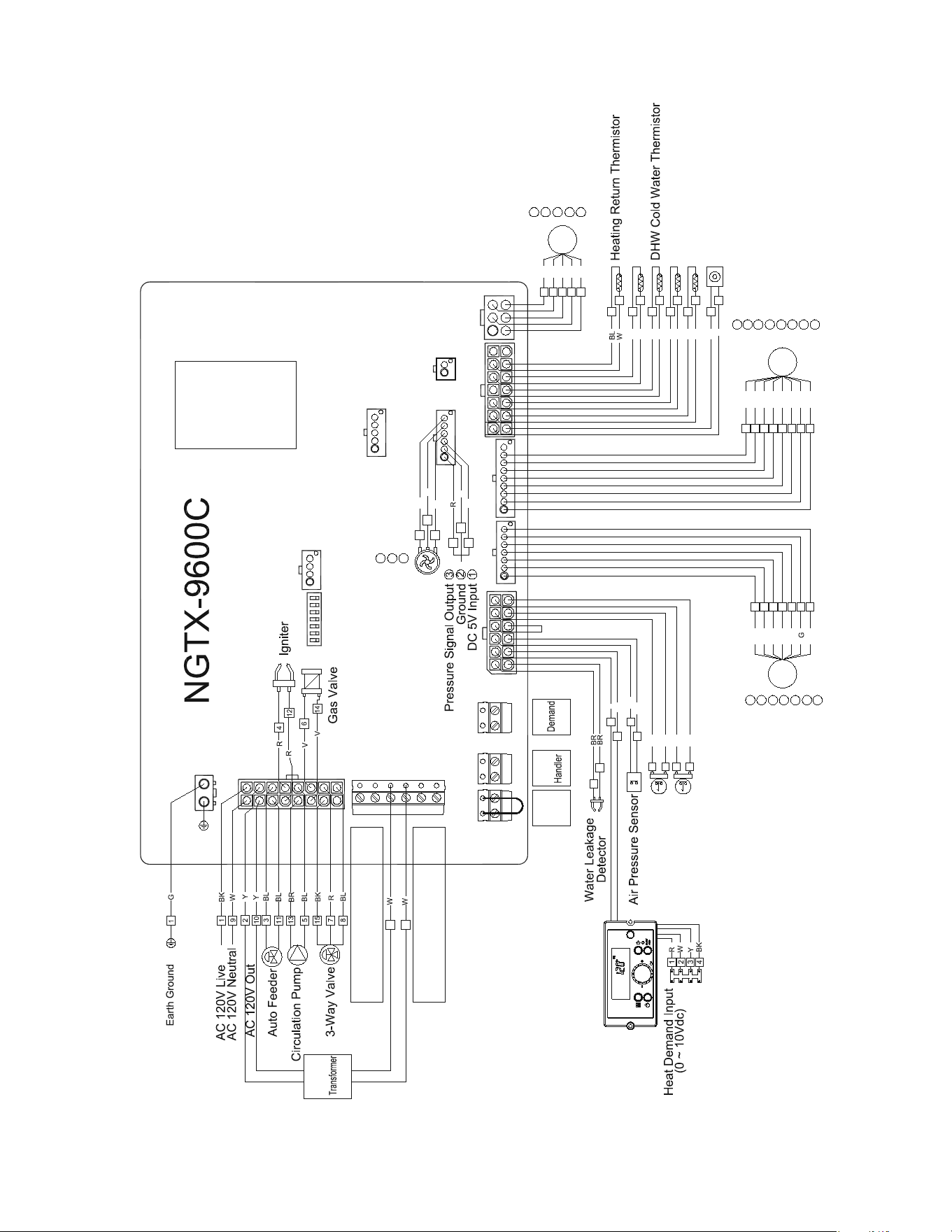
Figure 25 – Electrical Wiring Diagram
3
Fan Start Coil
GND
Fan End Coil
DC 14V
RPM Sensor
6
2
5
4
Burner Limit Switch
High Limit Switch
3
9
5
11
6
12
BK
BK
R
R
BL
BL
AGM /Y Phase
1
BK 1
AGM Y Phase
AGM /X Phase
AGM X Phase
GND
AGM Position Sensor
DC 24V
5
4
3
2
6
7
M
Y
O
R
BR
6
5
4
2
3
W
7
AGM
(Air Gas Mixer)
DHW Thermistor
Heating Supply Thermistor
2
9
3
10
4
11
BK
BK
R
R
BL
BL
5
12
BR
BR
1
8
BK
R
M
R
BL
Y
W
BK
3
6
2
5
4
Exhaust Thermistor
6
BL
5
W
4
R
DC 5V Input
Flow Signal Output
Ground
5
4
6
2
8
R
W
DIP Switch
Flame Sensor
3
4
6
13
1
2
3
G
BK
M
BL
BK
R
W
G
6
5
4
2
3
O7
Y1
Flow Control Valve
BR8
Water Flow Sensor
Flow Contol Valve Y Phase
Flow Control Valve /Y Phase
Flow Contol Valve X Phase
Flow Control Valve /X Phase
GND
Flow Contol Valve Position Sensor
5
4
3
1
2
6
7
8
DC 14V
DC 14V
Fan Motor
1
7
AC 24V Input
Outdoor Temperature
Sensor
AC 24V
Low
Water
Cut Off
Air
Heat
(T-T)
External Pump Output
Max 2.0 Amp
External AC 24V Output
Max 0.5 Amp
CN4
CN7
CN14
CN12
CN11
CN15
CN20
CN22
CN17
CN18
CN9
CN3
Color Designations
(15-3.11 of ANSI Y14.15)
Black
Brown
Red
Orange
Yellow
Green
Blue
Violet
Gray
White
(BK)
(BR)
(R)
(O)
(Y)
(G)
(BL)
(V)
(GY)
(W)
Control Panel (P-960C)
42
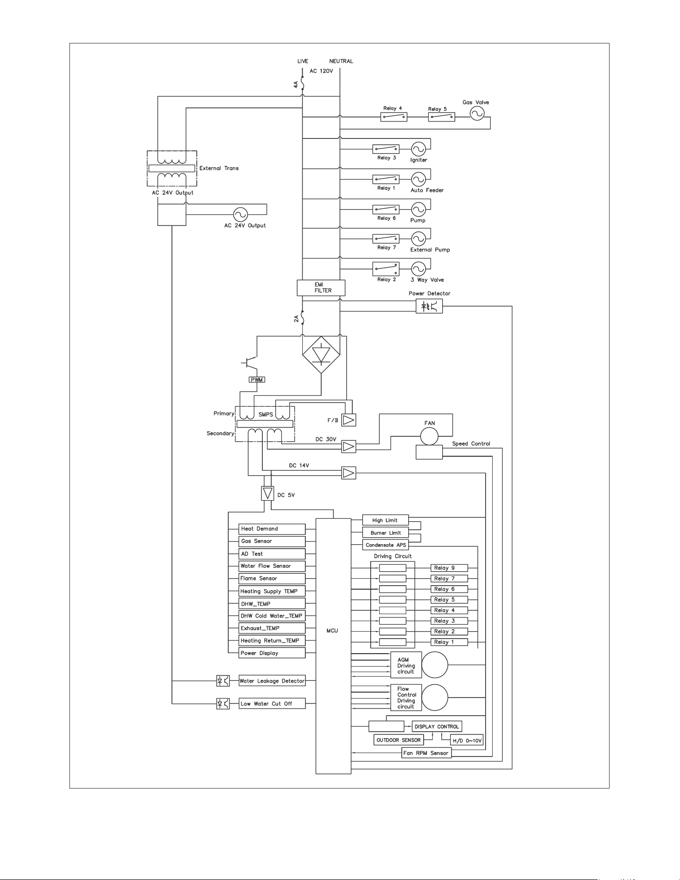
Figure 26 – Ladder Diagram
43
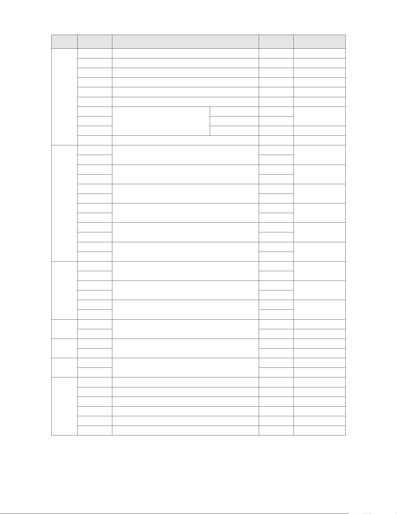
Table 17 – Appliance Wiring 1
CN No. Pin No. Part Color Normal Value
1,9
3,11
BL/BL
4,12
R/R
Circulation Pump BL/BR
V/V
R
BL
Common
Common
N/A - -
CN11
1
BR
DC 14 V
BR
2
R
DC 14 V
W
3
Air Pressure Sensor
BL
DC 14 V
9
BL
4
N/A
-
-
-
Burner Limit Switch
DC 14 V
11
R
DC 14 V
12
R
1
External Pump
-
2
-
3
AC 24V Input
W
AC 24 V
4
W
AC 24V Output
-
AC 24 V
-
1
- -
2
- -
CN22
1
Low Water Cut Off
- -
2
- -
1
- -
2
- -
CN4
1 N/A - -
2 Ground BL
3 R DC 14 V
4 W
DC 14 V
44
Table 18 – Appliance Wiring 2
CN No. Pin No. Part Color Normal Value
1
R
2
9
3
R
R
4
BL
11 BL
BR
12 BR
W
13 BL
N/A
-
-
14 -
CN12
1 DC 24 V
2 BR DC 24 V
3 AGM /X Phase R DC 24 V
4 AGM X Phase O DC 24 V
Ground DC 24 V
AGM Position Sensor G DC 24V
VDD W DC 24 V
CN14
1 GND DC 14 V
2 G DC 14 V
3 DC 14V W DC 14 V
4 R DC 14 V
DC 14 V
DC 14V BL DC 14 V
O DC 14V
BR DC 14 V
CN3
1 VCC R
2 Ground
3 Pressure Sensor G
4 VCC R
W
Ground BL
CN9
1 Case Earth G -
2 N/A - -
¶m¶j
¶m ¶j
¶m¶j
-
Status Display Mode
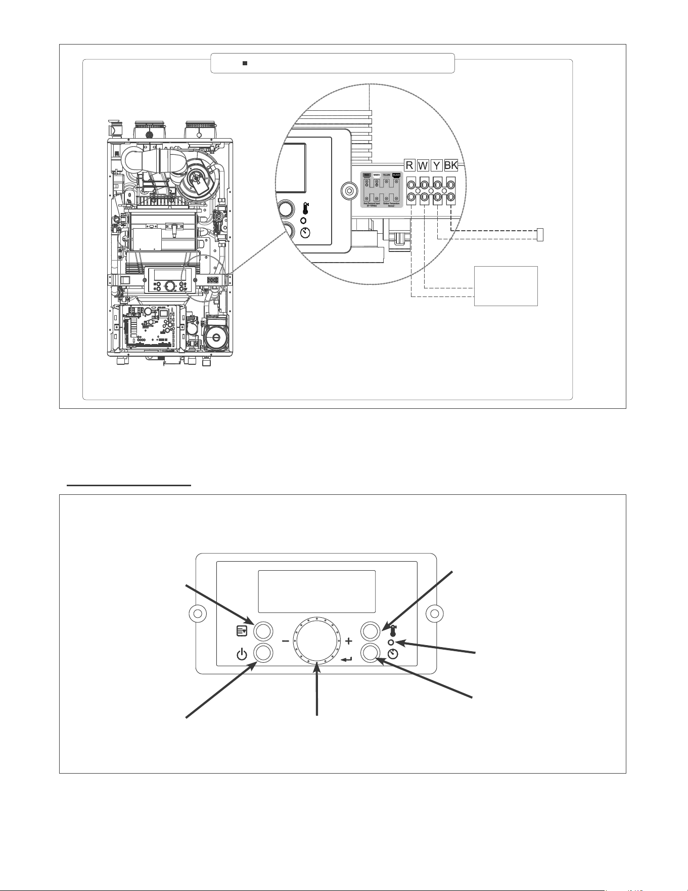
Figure 28 – Appliance Control Panel Detail
Figure 27 – Terminal Block Wiring Detail
PART 10 – OPERATING SYSTEM INSTRUCTIONS
ƓA. CONTROL PANEL
Sensor
Connection
Outdoor Temperature Sensor Connection
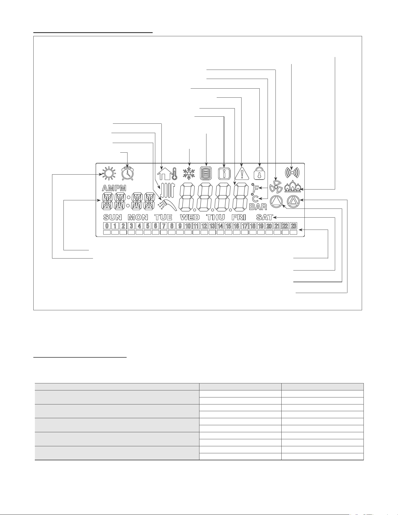
ƒ%/&'',63/$<'(6&5,37,216
ƒ&67$57836(48(1&(
Figure 29 – LCD Display Detail
Table 19 – Start-Up Sequence
Display Items Time for Display Remarks
LCD Test
1 Sec
Category
1 Sec Pdn
1 Sec
Software Version for Front Panel
1 Sec SPn
1 Sec
Software Version for Appliance
1 Sec
1 Sec XX.XX
Hardware Version for Appliance
1 Sec
1 Sec
Clock
DHW Preheat Scheduled Hours
Current and DHW Preheat scheduled Day
Internal Pump Icon
Heating activated Icon
Status Display
DHW High Temperature Icon
Temperature Unit
Lock Mode Icon
Communication Status
Burner ON Icon
External Pump(Heating) Icon
Air Handler Icon
Warm Weather
Cutoff Icon
DHW Preheat
activated Icon
Outdoor Reset Icon
DHW activated Icon
DHW Preheat Timer Icon
Information Icon
Freeze
Prevention Icon
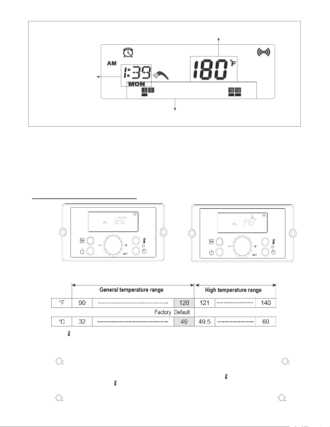
CURRENT TIME : AM 1:39
CURRENT DAY : MONDAY
DHW Preheat is scheduled to run Monday 5:00am~6:30am and
6:00pm~8:00pm
Heating Temperature Setting: 180
°F
[ Example ]
Figure 30 – Initial Display Screen Example
• Lock Mode
• Error Mode
• Status Display Mode
• Installer Mode
NOTE:
NOTE:
¶m (49
j¶m¶j
¶m (49¶j
¶m¶j
¶m¶j
Figure 31 – DHW Set-Point Screens
ƓD. CHANGING THE DHW SET-POINT
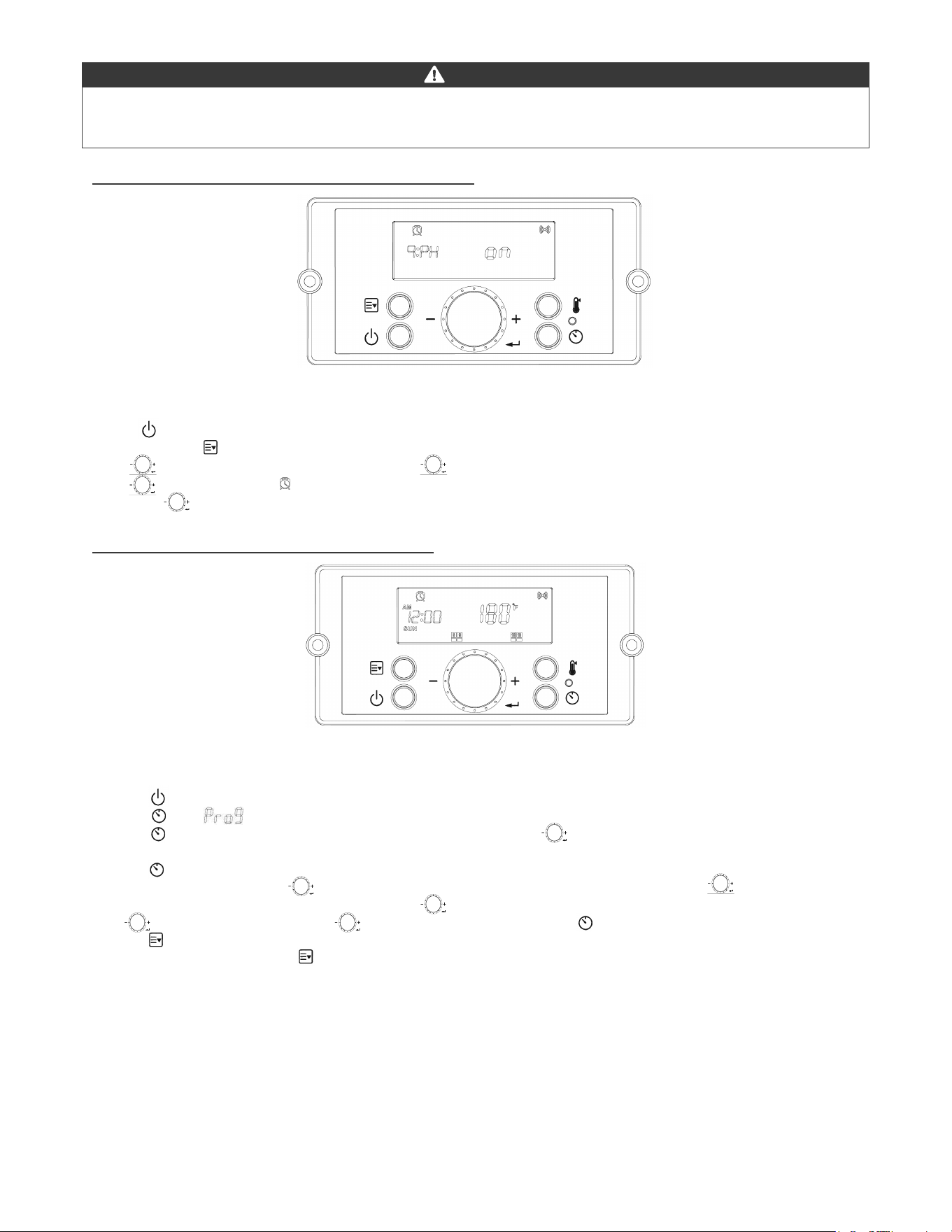
1. Press the ON.
displayed.
NOTE:
ƓE. SETTING FOR DHW PREHEAT ACTIVATION
ƓF. SETTING FOR DHW PREHEAT TIMERV
DANGER
Figure 32 – DHW Preheat Activation Screen
Figure 33 – DHW Preheat Timer Screen
49
parameters in this mode.
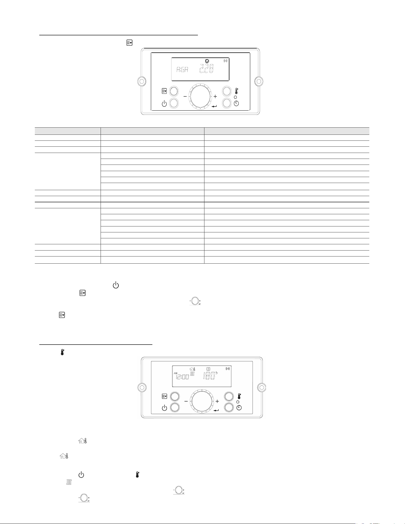
ƓG. STATUS DISPLAY MODE (or USER MODE)
ƓH. CHANGE THE CH SET-POINT
Table 20 – Status Mode Display Screen Descriptions
Parameter Detail Description
A: GA/L
Lock Mode
d.CLd
Eht
Od
E:WP
I:MD
Current Gas type
NOTE:
Press the ON. Press the Button.
Figure 34 – Status Mode Screen
Figure 35 – CH Set-Point Screen
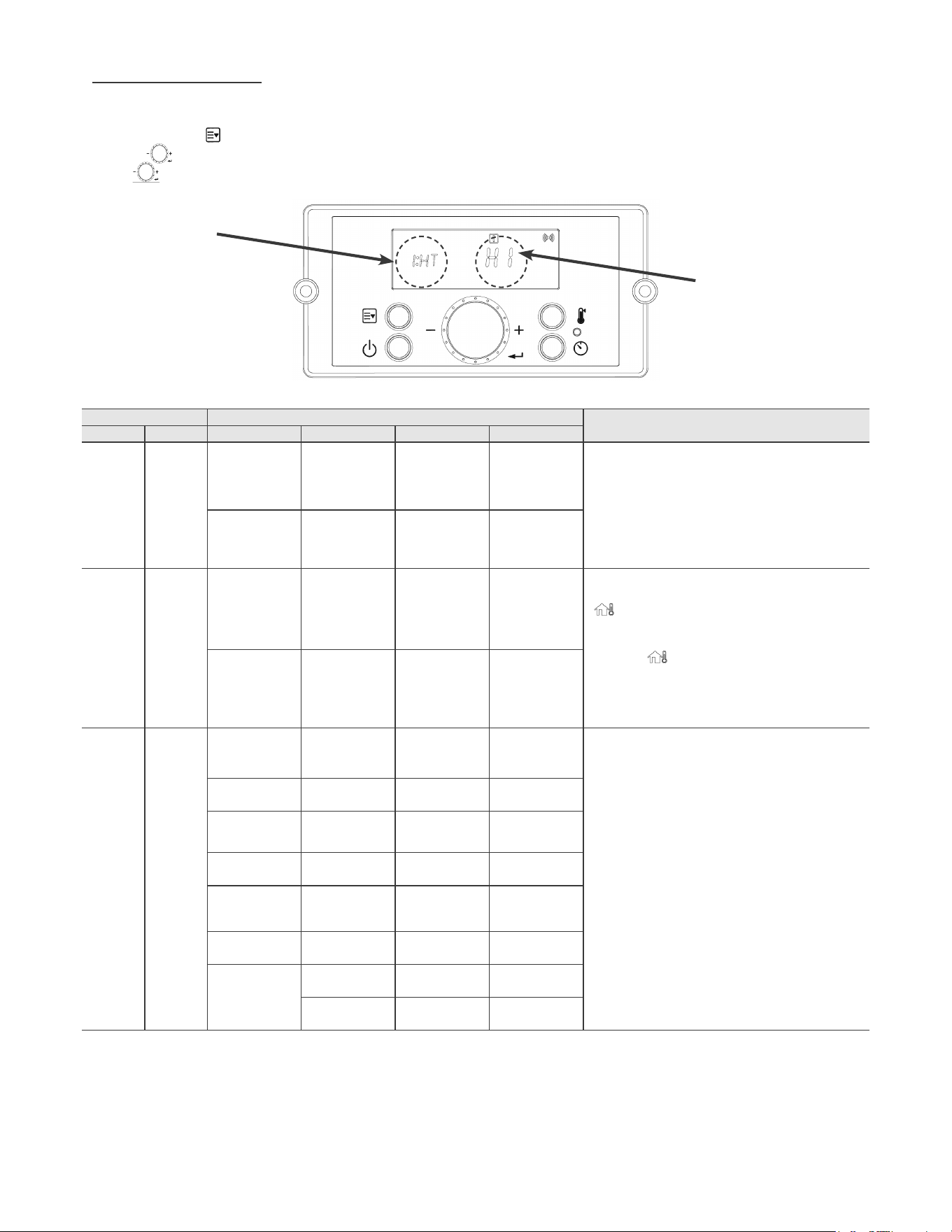
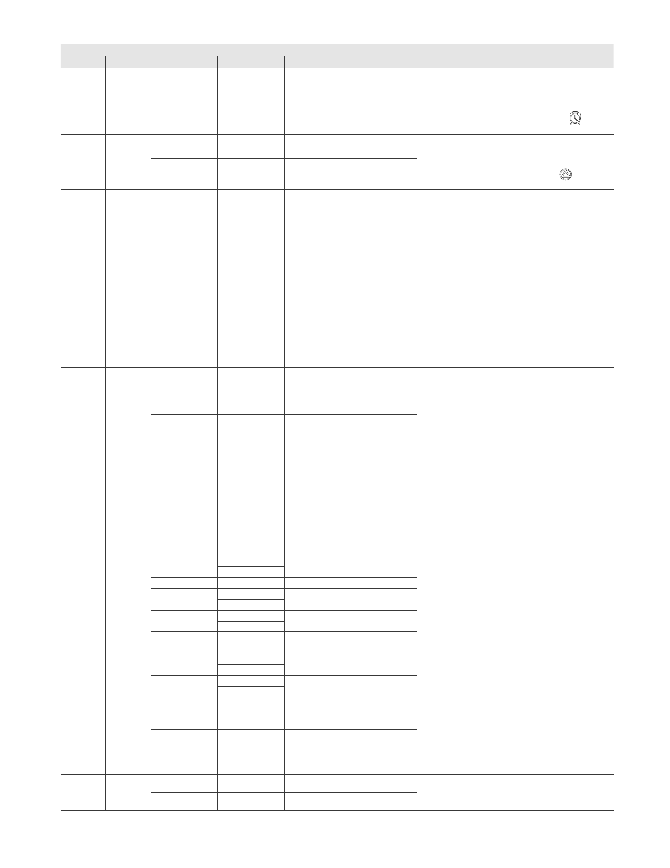
ƓI. INSTALLER MODE
Secondary Show
Primary Show
Primary Show Secondary Show
Description
Parameter Index Step 1 Step 2 Step 3 Default
¶m
¶j
-
¶m
¶j
-
Lo
¶m
¶j
-
¶m
¶j
Outdoor
- - O
-
ture Reset function.
-
• Please check the connection of the outdoor temperature
-
automatically.
on - - -
param-
eter doesn’t
show if
System
- -
O
¶m
¶j
-
-Radiator
points are
- -
¶m
¶j
- -
¶m
¶j
- -
¶m
¶j
- -
¶m
¶j
- -
¶m
¶j
G.CUS
¶m
¶j
¶m
¶j
LO
¶m
¶j
¶m
¶j
Figure 36 – Installer Mode Screen
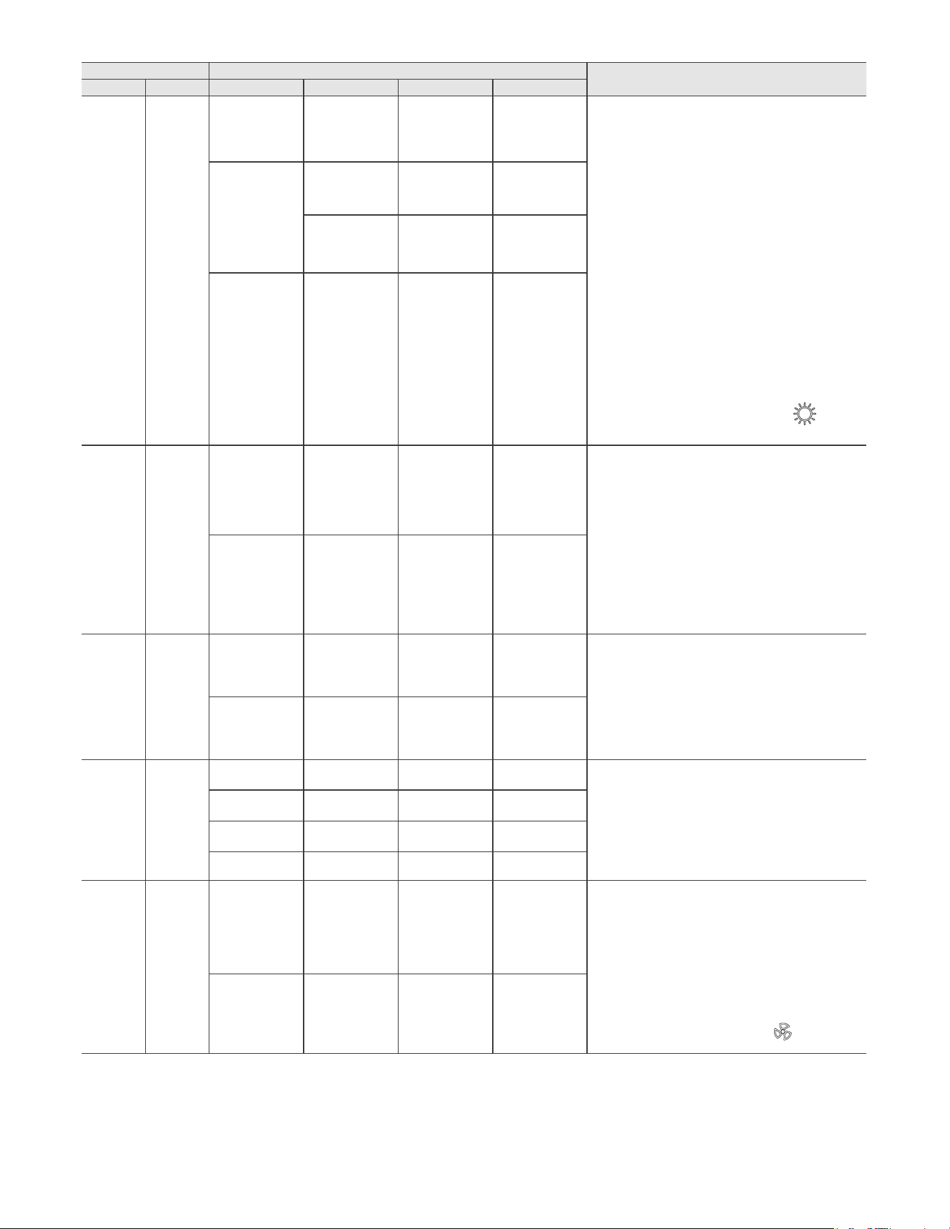
Primary Show Secondary Show
Description
Parameter Index Step 1 Step 2 Step 3 Default
4:Od
param-
eter doesn’t
Outdoor
¶m
¶j
-
O
¶m
(21¶j
-
system to continue to heat the home.
on the control panel.
on - O
- -
C.Lo
¶m
¶j
-
O
¶m
¶j
param-
eter doesn’t
Boost
- - O
on cold start ups if the actual room temperature doesn’t
Boost time function will increase the set temperature of
Example :
- - -
Vent
Material
PVC - - O
Vent Material function is used to limit the maximum
CPVC - - -
- - O
- - -
- - -
- - -
- - O
the control panel.
on - - -
Primary Show Secondary Show
Description
Parameter Index Step 1 Step 2 Step 3 Default
- - O
set.
displayed on the control panel.
on - - -
External
Pump
- - O
on the control panel.
on - - -
11:WP
Water
Pressure
- - -
-
rectly.
12:IV - - 3 min
13:Or
Pump
-
pump and extend the life of the pump.
- 3 min
Burner Set
¶m
¶j
-
¶m
¶j
Mode.
-
¶m
¶j
-
¶m
¶j
Check Parts
A.PP
on
on
on
on
Clear
no
no
SyS
no
no
Compensation
mode.
mode.
rate
Table 21 – Installer Mode Descriptions
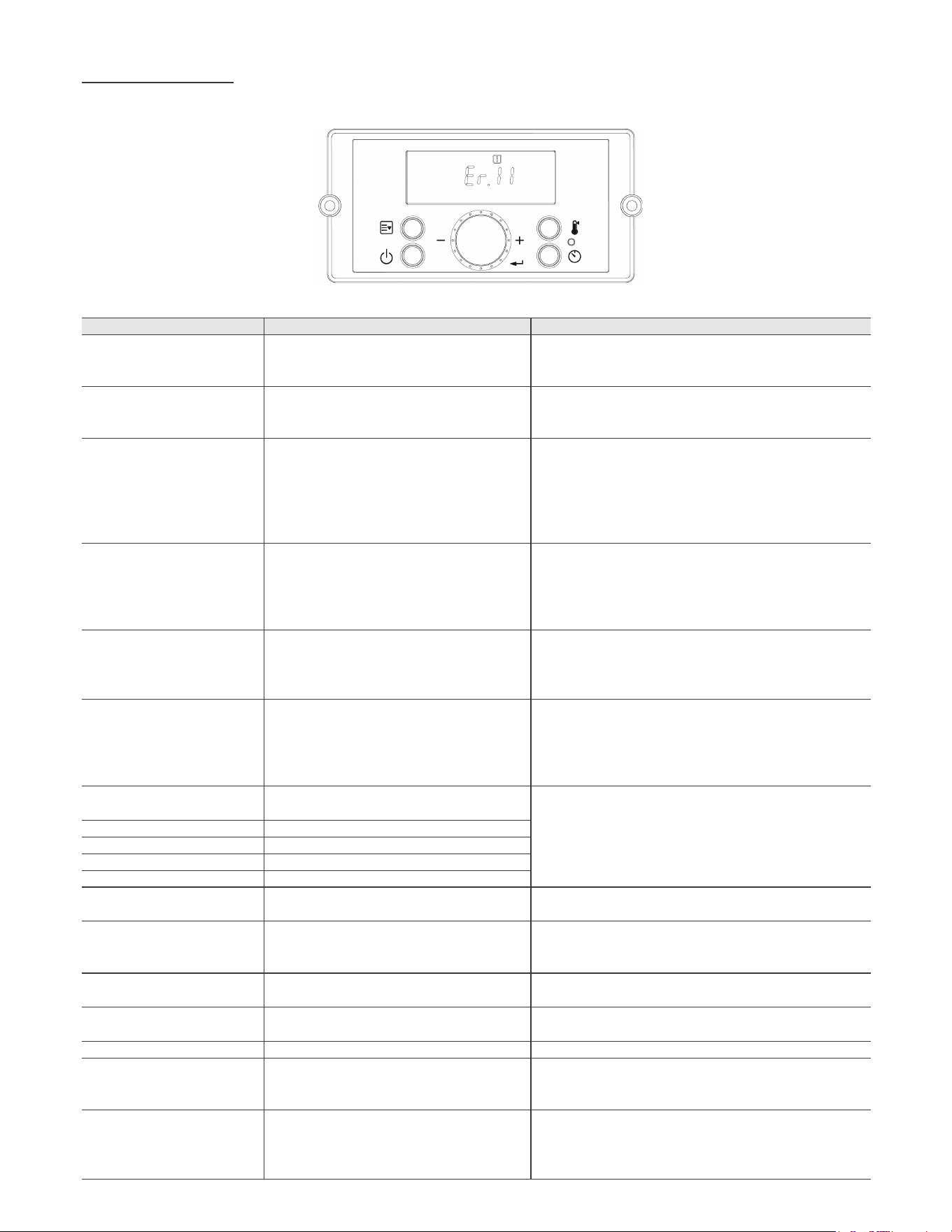
ƒ-(552502'(
Code Error Code Description Possible Remedies
Er11
-
cation.
Er12
restarts it.
speed.
restart it.
Er29
• Make sure that the condensate trap or drain pipe is not
Circuit
• Check outdoor temperature sensor. Ensure connections are
secure.
sensor.
• Contact technical support.
Er31
Circuit
• Ensure connections are secure.
sensor.
Er32
Er33
Er34
Circuit Board
Er39
• Contact technical support.
Er41
and then reconnected.
Er43 • Contact technical support.
-
port.
• Contact technical support.
• Check the auto feeder.
• Check the auto feeder inlet pressure.
• Check the pressure sensor.
Figure 37 – Error Mode Screen

Code Error Code Description Possible Remedies
Stop Supply Inlet Water.
least 13 psi.
• Check the auto feeder.
• Check the pressure sensor.
• Contact technical support.
case of external LWCO install.
• Make-up water to the system if necessary.
• Contact technical support.
• Check the pressure sensor.
• Contact technical support.
RPM Sensor • Check fan motor.
restart it.
and then reconnected.
Er73
Er76
CircuitBoard.
• Check connections from Circuit Board to Control Panel.
and then reconnected.
Er94
Boiler shuts down when the exhaust temperature
restart it.
Table 22 – Error Codes with Linked Components, Effects, and Actions
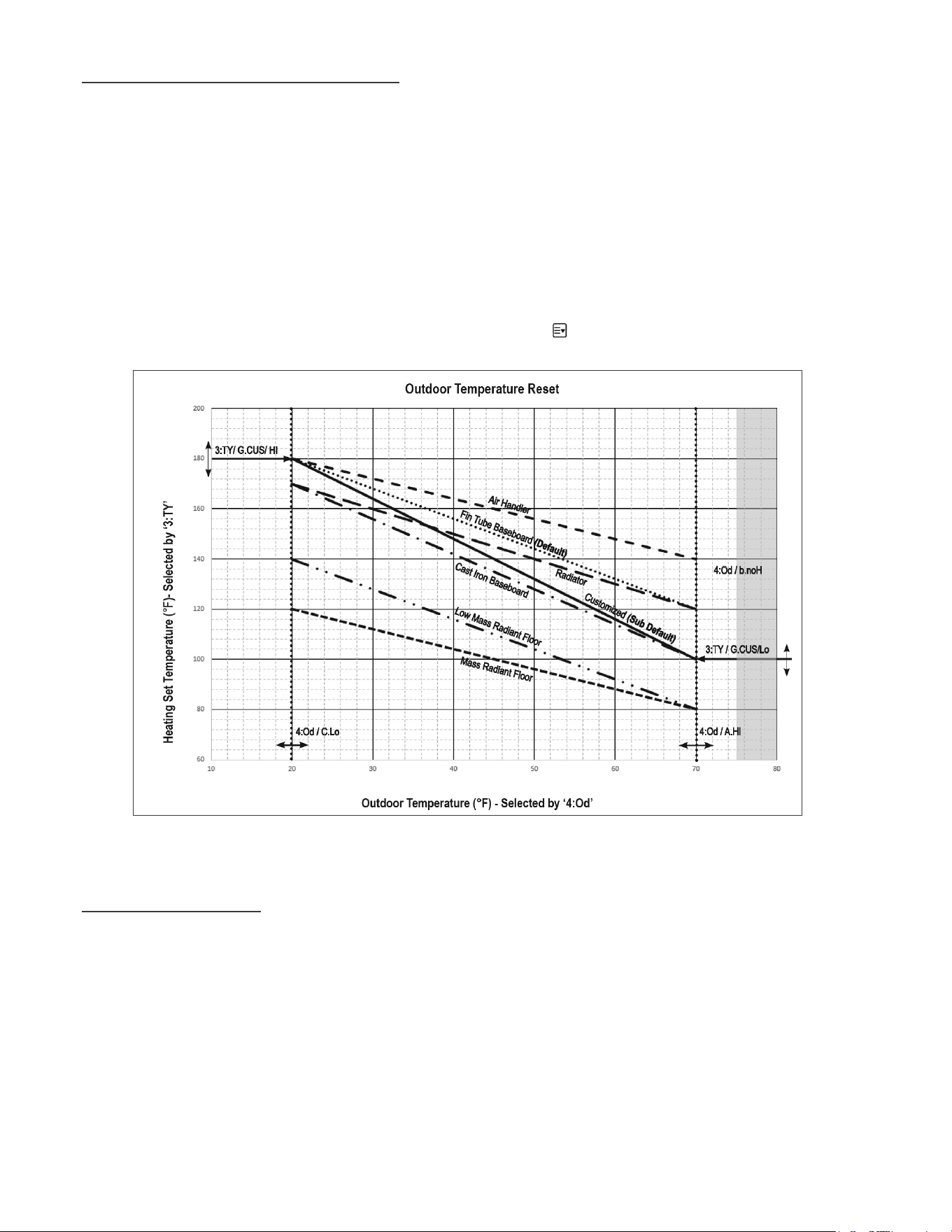
ƒ.287'2257(03(5$785(02'(
NOTE:
NOTE:
NOTE:
NOTE:
panel is powered on.
ƒ/a92/7,1387
NOTE:
NOTE:
NOTE:
Figure 38 – Outdoor Reset Curve – See Installer Mode for Curve Setting Descriptions
NOTE:
0-10 V INPUT TABLE:
professional.
Input Voltage[V]
Heat Temperature [¶C]
Heat Temperature [¶F]
91
- - -
Contaminant Maximum Allowable Level Contaminant
Maximum Allowable Level
¶m
¶m
Aluminum Sulfate
Chloride
Copper Zinc
Iron
(CO
2
Table 23 – 1~10V Input Voltage and Associated Temperature
7DEOH²:DWHU&KHPLVWU\6SHFLÀFDWLRQV
PART 11 – START-UP PREPARATION
ƓA. CHECK / CONTROL WATER CHEMISTRY
WARNING
CAUTION
NOTE:
NOTE: APPLIANCE FAILURE DUE TO IMPROPER WATER CHEMISTRY IS NOT COVERED BY WARRANTY.
Clean system to remove sediment*
ㆍ
ㆍ
ㆍ
32¶¶
ㆍ
ㆍ
ㆍ
NOTE
ƓB. GLYCOL ANTIFREEZE SOLUTIONS
ƓC. CHECK FOR GAS LEAKS
WARNING
WARNING
Use only inhibited propylene glycol solutions which are specially formulated for hydronic systems. Ethylene glycol is toxic and can
attack gaskets and seals used in hydronic systems. Glycol mixtures should not exceed 50%.
%HIRUHVWDUWLQJWKHDSSOLDQFHDQGGXULQJLQLWLDORSHUDWLRQVPHOOQHDUWKHÁRRUDQGDURXQGWKHDSSOLDQFHIRUJDVRGRUDQWRUDQ\XQXVXDO
odor. Remove appliance front door and smell interior of appliance enclosure. Do not proceed with startup if there is any indication of a
gas leak. Repair any leaks at once.
PROPANE APPLIANCES ONLY – Both natural gas and propane (LP) have an odorant added to aid in detecking a gas leak. Some
people may not physically be able to smell or recognize this odorant. If you are unsure or unfamiliar with the smell of natural gas or
LP, ask the gas supplier. Other conditions, such as "odorant fade," which causes the odorant to diminish in intensity, can also hide or
FDPRXÁDJHDJDVOHDN
It is highly recommended to carefully follow the glycol manufacturer’s recommended concentrations, expansion requirements, and
maintenance recommendations (pH additive breakdown, inhibitor reduction, etc.) You must carefully calculate the additional friction
ORVVLQWKHV\VWHPDVZHOODVWKHUHGXFWLRQLQKHDWWUDQVIHUFRHIÀFLHQWV
CAUTION
WARNING
WARNING
WARNING
WARNING
FOR YOUR OWN SAFETY READ BEFORE OPERATING
1. This appliance does not have pilot. It is equipped with an ignition device which automatically lights the burner. Do not try to light the
WHAT TO DO IF YOU SMELL GAS
ㆍ
Do not try to light any appliance.
ㆍ
Do not touch any electric switch; do not use any phone in your building.
ㆍ
Immediately call your gas supplier from a neighbor's phone. Follow the gas suppliers' instructions.
ㆍ
,I\RXFDQQRWUHDFK\RXUJDVVXSSOLHUFDOOWKH¿UHGHSDUWPHQW
ㆍ
Turn off gas shutoff valve (located outside of the appliance) so that the handle is crosswise to the gas pipe. If the handle will
QRWWXUQE\KDQGGRQWWU\WRIRUFHRUUHSDLULWFDOODTXDOL¿HGVHUYLFHWHFKQLFLDQ)RUFHRUDWWHPSWHGUHSDLUPD\UHVXOWLQD¿UHRU
explosion.
ƓD. FILL AND TEST WATER SYSTEM
ƓE. PURGE AIR FROM CH
CAUTION
CAUTION
IMPORTANT!
WARNING
ƓF. PURGE AIR FROM DHW SYSTEM
ƓG. CHECK THERMOSTAT CIRCUIT(S)
To purge air from the system:
counterclockwise from off to on.
ƓH. CONDENSATE REMOVAL
ƓI. FINAL CHECKS BEFORE STARTING APPLIANCE
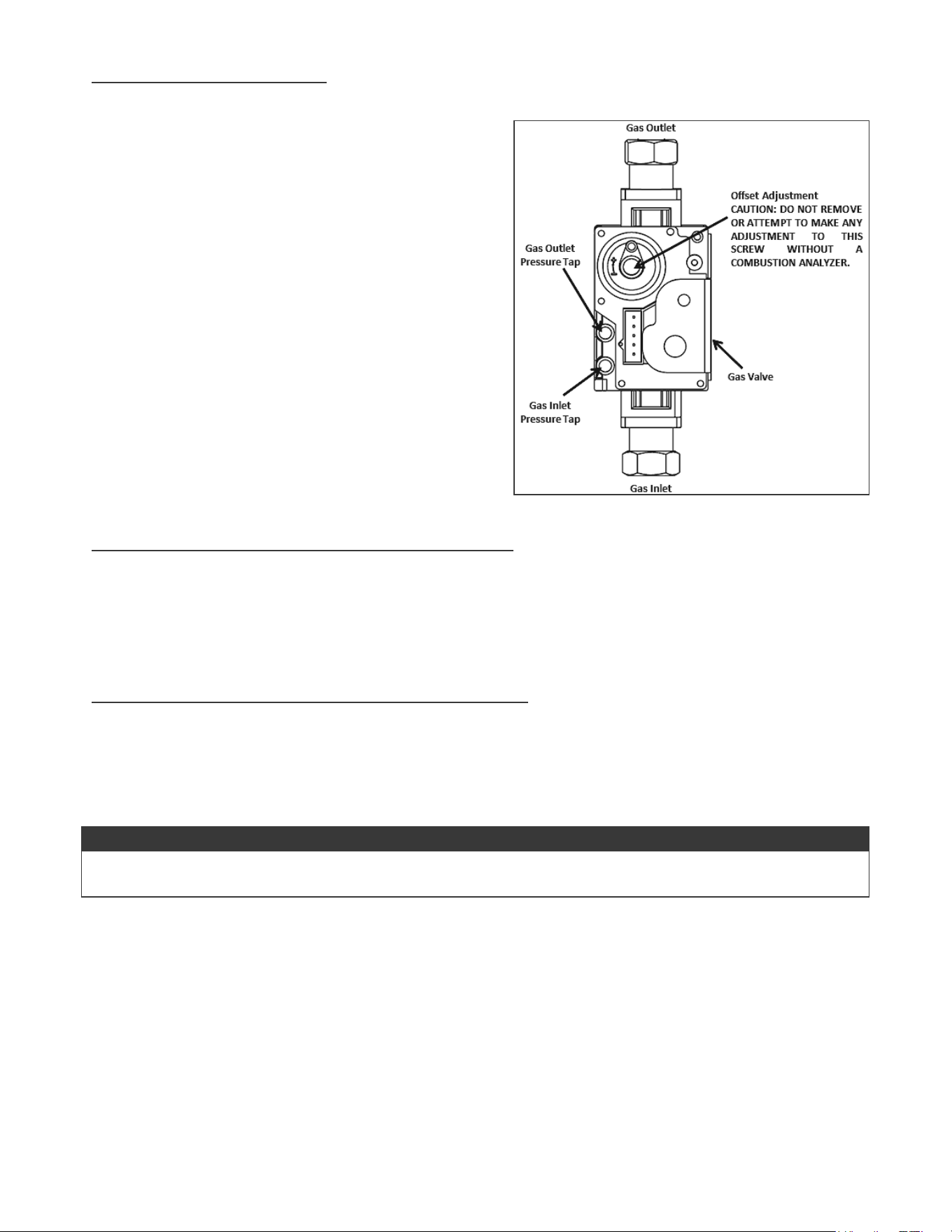
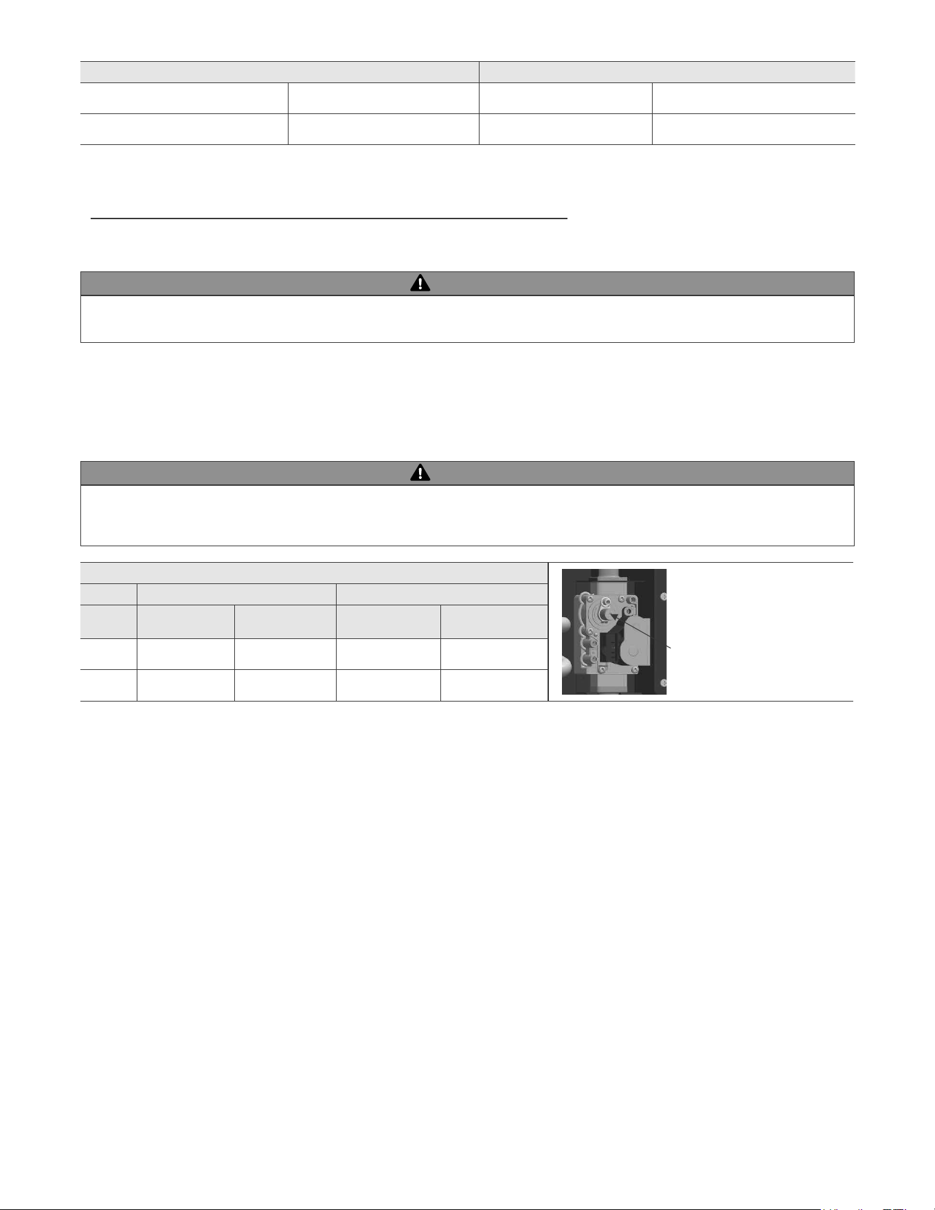
ƓJ. ADJUSTING GAS PRESSURE AT THE APPLIANCE
when it is initially started.
from aftermarket
1. Verify the appliance and system are full of water and all system components are correctly set for operation.
3. Verify electrical connections are correct and securely attached.
NOTE
ADJUSTING GAS PRESSURE AT THE APPLIANCE
Figure 39 – Gas Valve Detail
NOTICE
COMBUSTION SETTINGS
NATURAL GAS LP GAS
FAN
SPEED
LOW HIGH LOW HIGH
CO PPM
CO
2
ƓK. SETTING AND VERIFYING THE COMBUSTION SETTING
*In order to increase COဌဌ
Figure 40 – Gas Valve Offset
Screw
Offset Screw
NOTEဌ
LP GAS NATURAL GAS
Minimum Pressure " WC Minimum Pressure " WC
Maximum Pressure " WC Maximum Pressure " WC
Table 25 – Gas Pressure Requirements
Table 26 – Combustion Settings
WARNING
WARNING
injury or death.
NOTE
LIGHT OFF ACTIVITIES DATE COMPLETED
YES NO
1) Fill the Heating System
with Water
2) Exhaust Vent and Intake
Piping
3) Condensate Piping / Tub-
ing and Components
4) Gas Piping
(supply line no less than ½"
5) Pressure Relief Valves
6) Wire the Appliance
7) Start-Up, Adjust, and
Test
2
FINAL INSTALLATION AP-
PROVALS
SIGNED BY TECHNICIAN DATE
PART 12 – INSTALLATION AND START-UP CHECKLIST
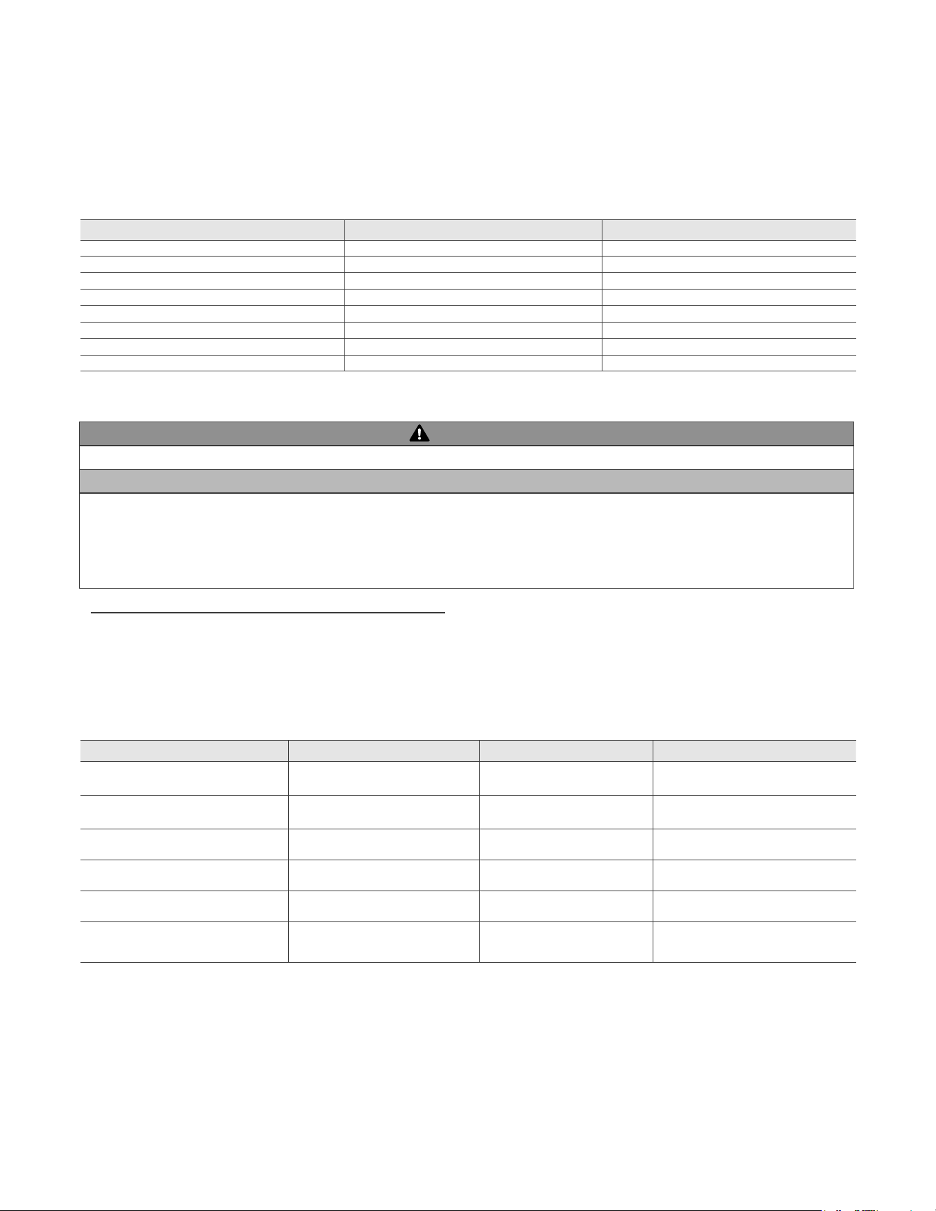
Table 27 – Final Installation Checklist
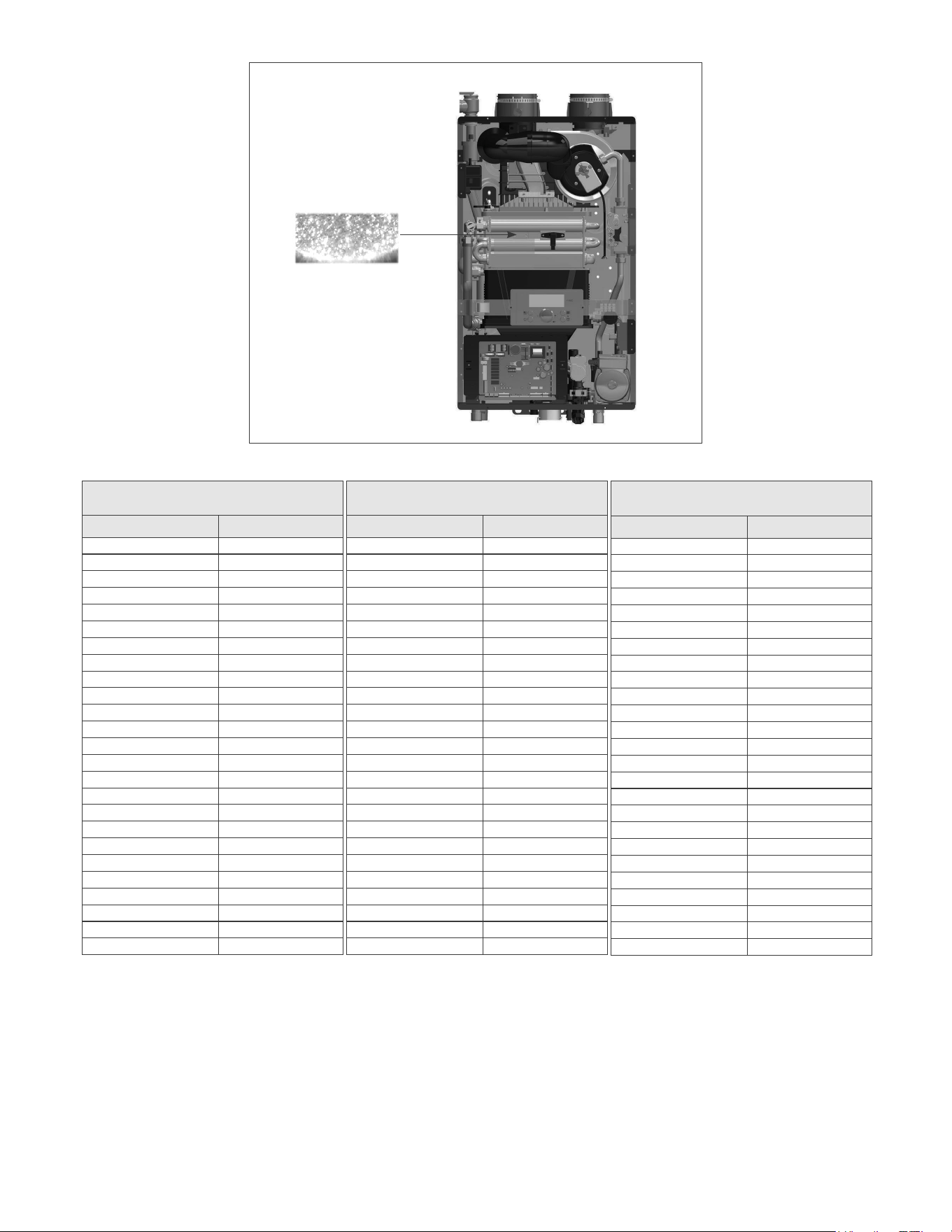
Table 28 – Temperature Sensor Resistance
Figure 41 – Flame Sight Glass
CH Return Temperature Sensor
Exhaust Temperature Sensor
7HPSHUDWXUHƖ) 5HVLVWDQFH
-4
14
23
32
41
113
122
131
149
194
212
CH Supply Temperature Sensor
DHW Temperature Sensor
7HPSHUDWXUHƖ) 5HVLVWDQFH
-4
14
23
32
41
3233
113
122
131
149
194
421
212
Outdoor Temperature Sensor
7HPSHUDWXUHƖ) 5HVLVWDQFH
-4
14
23
32
41
113
122
PART 13 – TROUBLESHOOTING
TROUBLESHOOTING CHART
PROBLEM POSSIBLE CAUSES
POSSIBLE REMEDIES
No electrical power to the appliance
4. Contact the power company.
opened
faucet is opened.
1. Restore electrical power to the unit.
manual.
manual.
3. Adjust the outlet water temperature (refer to the procedure
from the faucet.
off and drain the unit.
Display
Condition
Diagnostic
Possible Corrective Actions
on the display control
panel and no other
appliance components
power Control is not
connection of transformer to the control
Check transformer connection to the control
transformer
appliance is turned ON
power appliance
the manual switch
manual
Inspect the fuse. Replace as necessary
Replace the fuse with the proper part found in
the replacement part section of this manual.
Table 29 – Troubleshooting Chart
DIAGNOSTICS AND SUGGESTED CORRECTIVE ACTIONS
PART 14 – ANNUAL MAINTENANCE PROCEDURES
Display
Condition
Diagnostic
Possible Corrective Actions
Occurs when communica-
tions is lost from the control
to the display
-
Check for continuity on the wire harness from the
display to the control. See repair parts section for
proper replacement part.
switch and check for operation
Replace with new display module. See repair parts
section for proper replacement part.
Occurs when control does
switch and check for operation
Replace fan.
Table 30 – Diagnostics and Suggested Corrective Actions
Check the Surrounding Area
Combustible/Flammable Materials
immediately.
Air Contaminants
Ensure the Appliance Cabinet is Closed
Check the Power Source
Check the Status of the Control Panel
Check Exhaust Vent and Intake Pipe Terminations
death.
ㆍ
ㆍ
acid corrosion.
contaminated areas.
DANGER
DANGER
Check Exhaust Vent and Intake Piping
Check Pressure Relief Valve
ㆍ
ㆍ
the appliance and system.
Check Vent Condensate Drain System
ㆍ
ㆍ
ㆍ
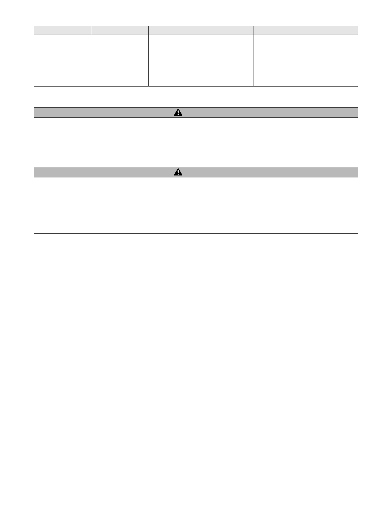
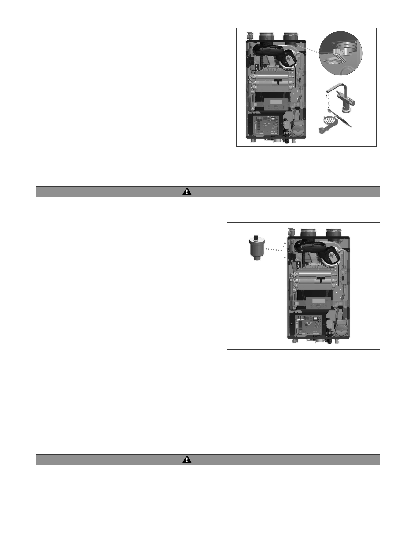
Check the Air Vent
Check Primary and Gas Piping
ㆍ
ㆍ
Operate Pressure Relief Valve
ㆍ
WARNING
WARNING
death.
Figure 43 – Air Vent Detail
Figure 42 – Cleaning the Air Intake Filter
Cleaning the Air Intake Filter
.
2. Disconnect the power supply from the .
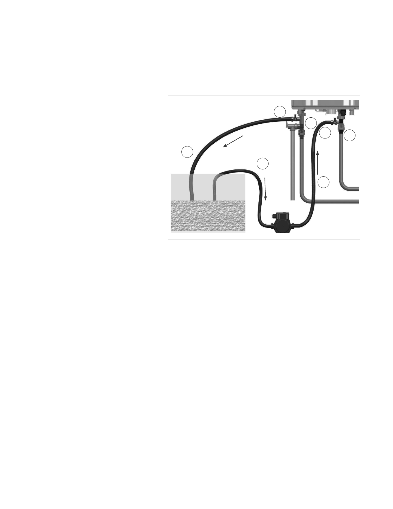
Figure 44 – Valve and Hose Connection Details
Check the Burner
Flushing the CH Closed Loop Heat Exchanger
NOTE: Improper maintenance WILL VOID appliance
warranty.
1. Disconnect electrical power to the appliance.
ㆍ
ㆍ
ㆍ
V1
V2
V4
V3
D1
D2
D3
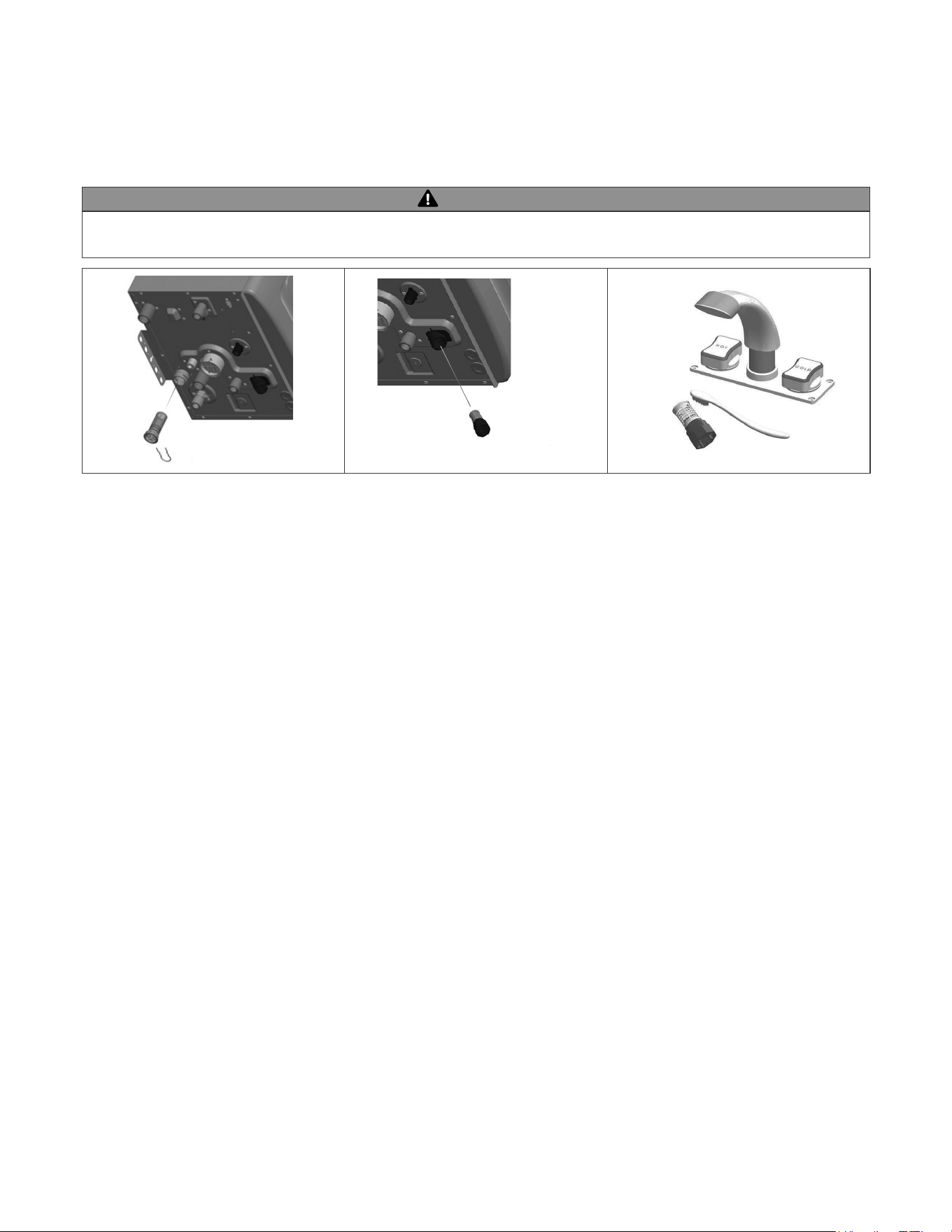
Cleaning the CH and DHW Inlet Filters (Draining the Appliance)
WARNING
Figure 45 – Cleaning the Inlet Filter
CH RETURN FILTER
DHW INLET FILTER
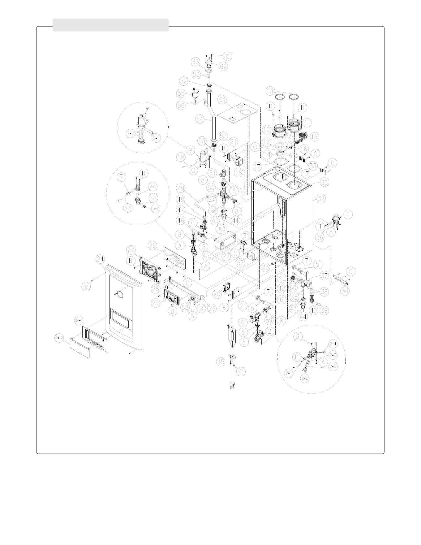
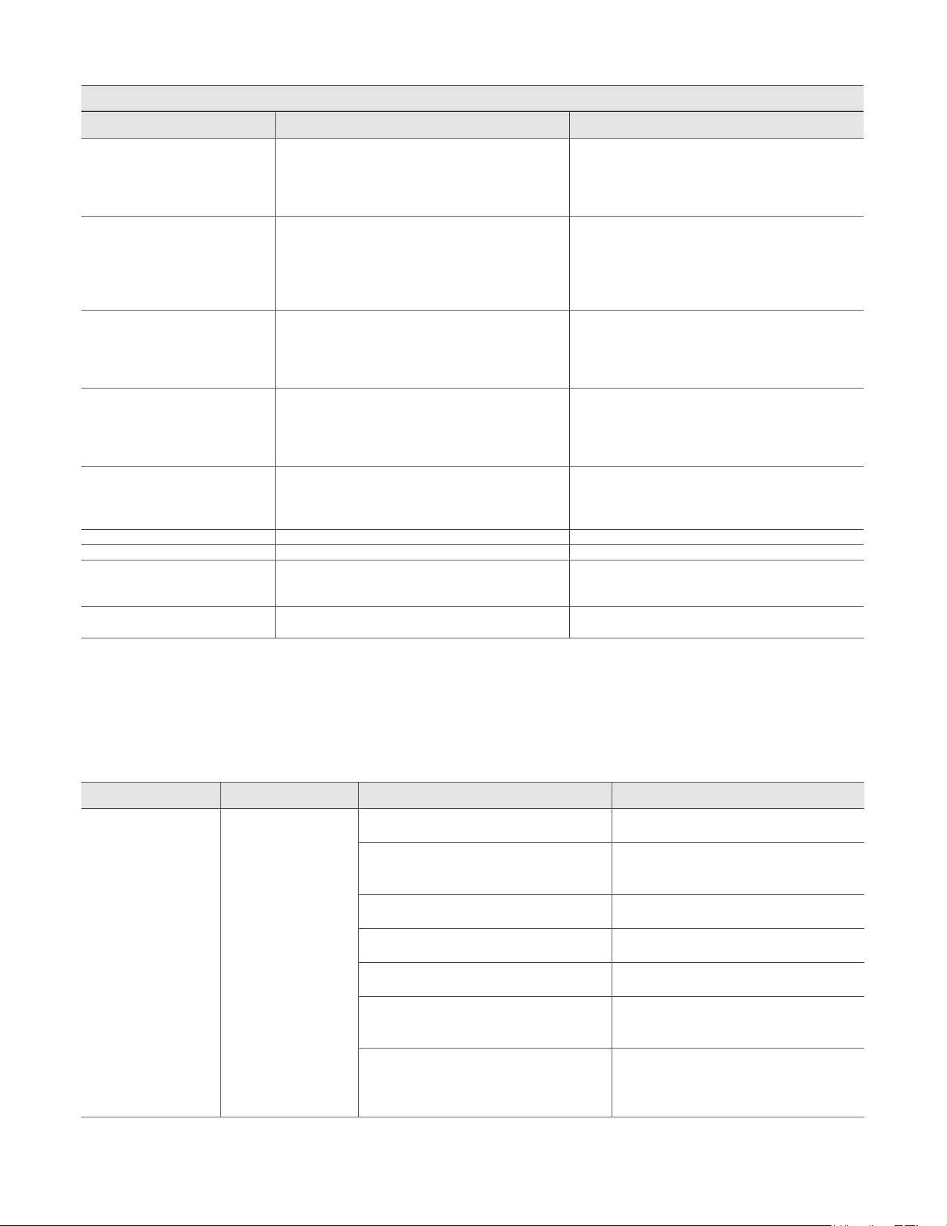
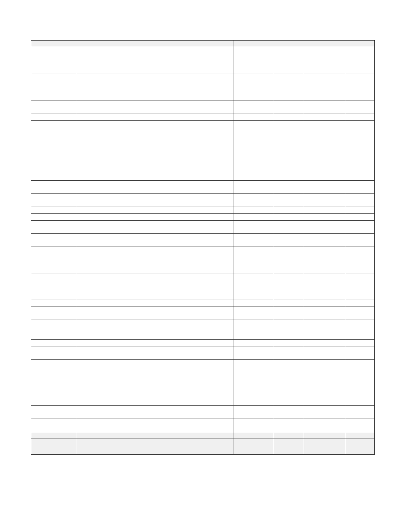
Figure 46 – CASE PART
PART I _ CASE PART
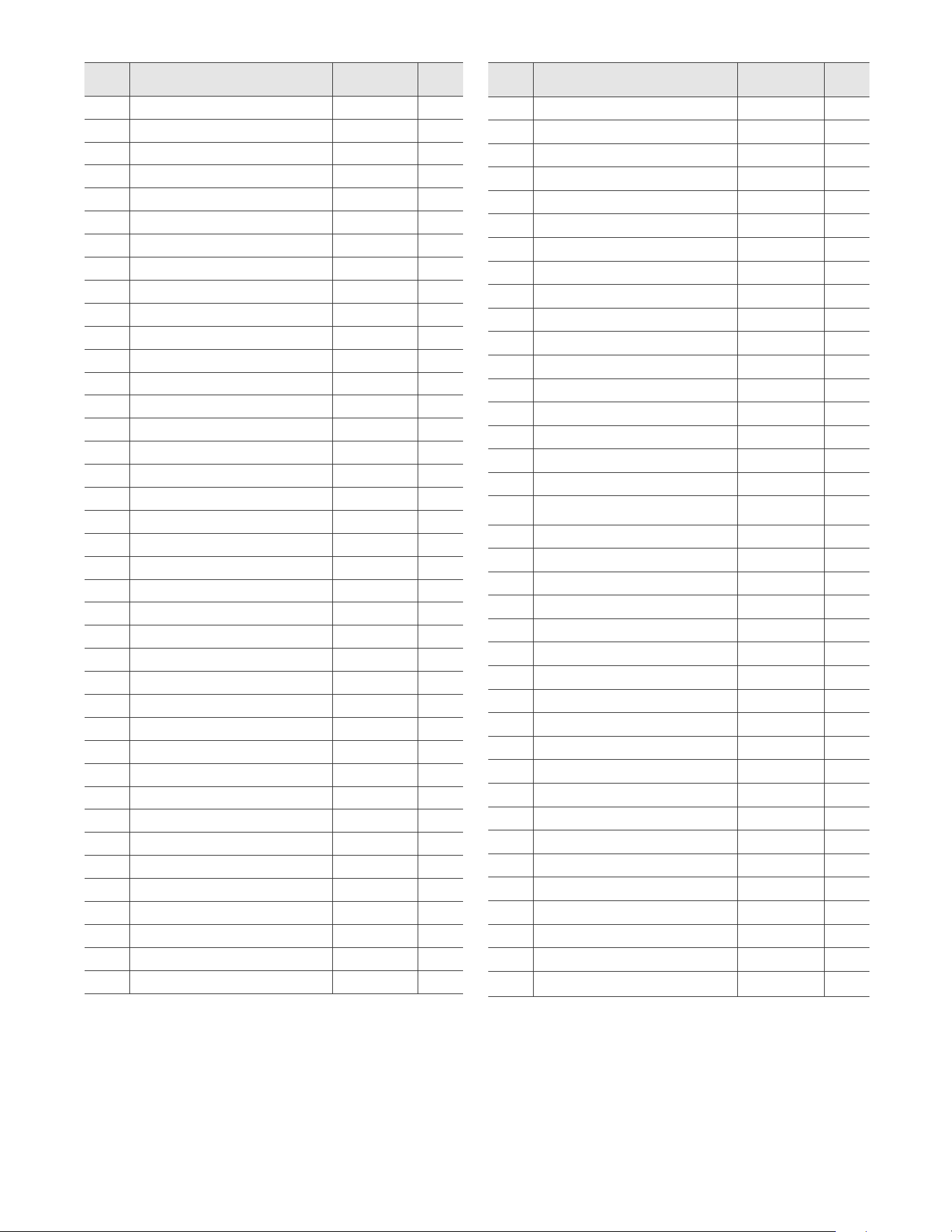
Item Description
1 Gas Inlet Connection 1
2 1
2-1 1
2-2 1
2-3 1
2-4 1
1
3 1
3-1 1
3-2 1
3-3 1
3-4 1
4 1
13
1
2
9 Condensate trap 1
9-1 Condensate clip 1
9-2 2
1
11 1
12 2
13 2
14 1
1
1
Gasket 2
1
19 1
Air Pressure switch 1
21 2
22 Water Leak Detector 1
23 1
24 1
24-1 Control Panel Bracket 1
24-2 Control Panel Window 1
Control Panel 1
Control Panel Steel Bracket 1
Item Description
1
Rocker Switch 1
29
Control Board Bracket 1
1
31
1
32
Case 1
33
Case Bracket 1
34
1
Power Cord 1
1
1
39
1
1
41
1
42
Cap Clip
2
43
2
44 2
1
1
1
2
49
1
1
1
2
4
1
Air Vent 1
1
1
1
1
2
1
1
1
Table 31 – Case Part
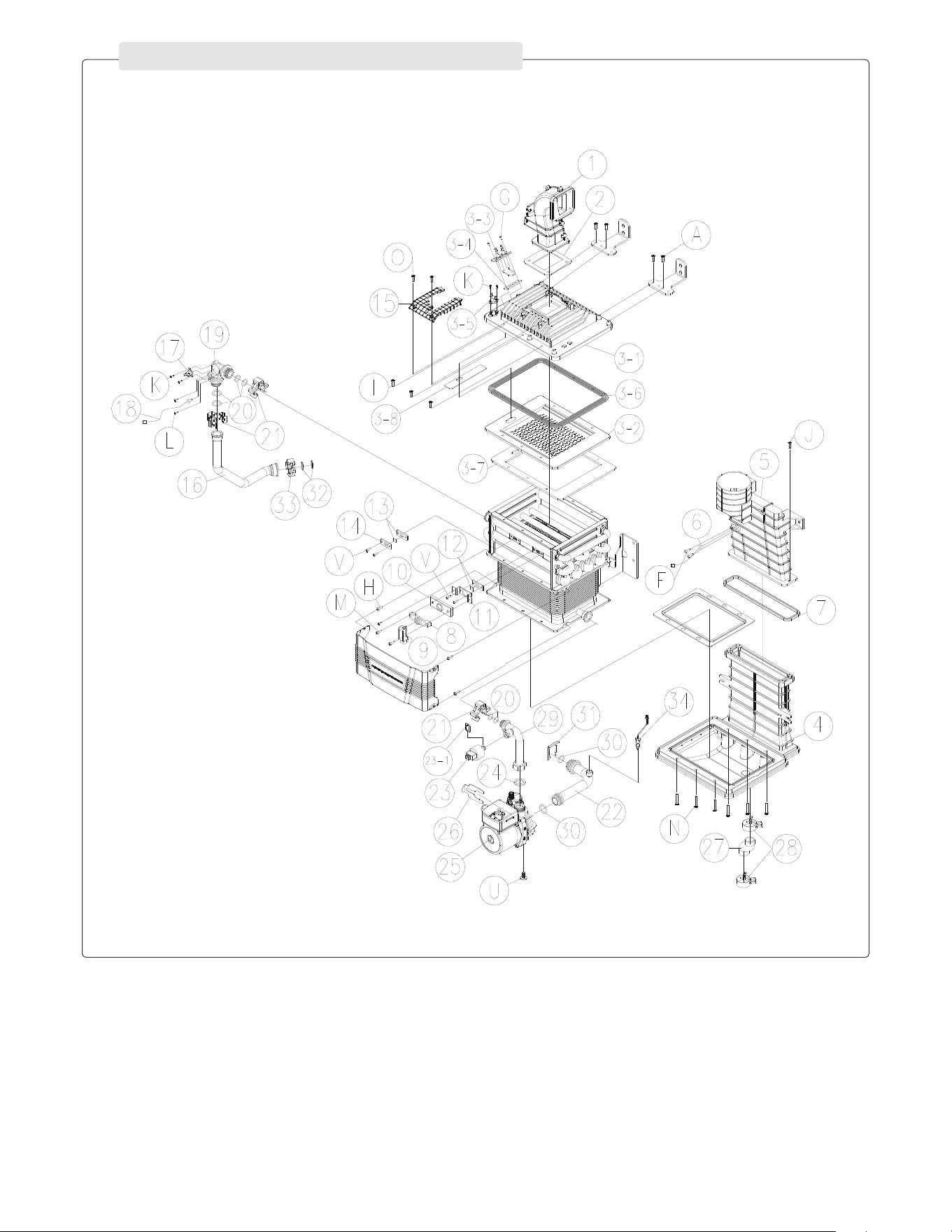
Figure 47 – Heat Exhchanger Part
PART II _ HEAT EXCHANGER PART
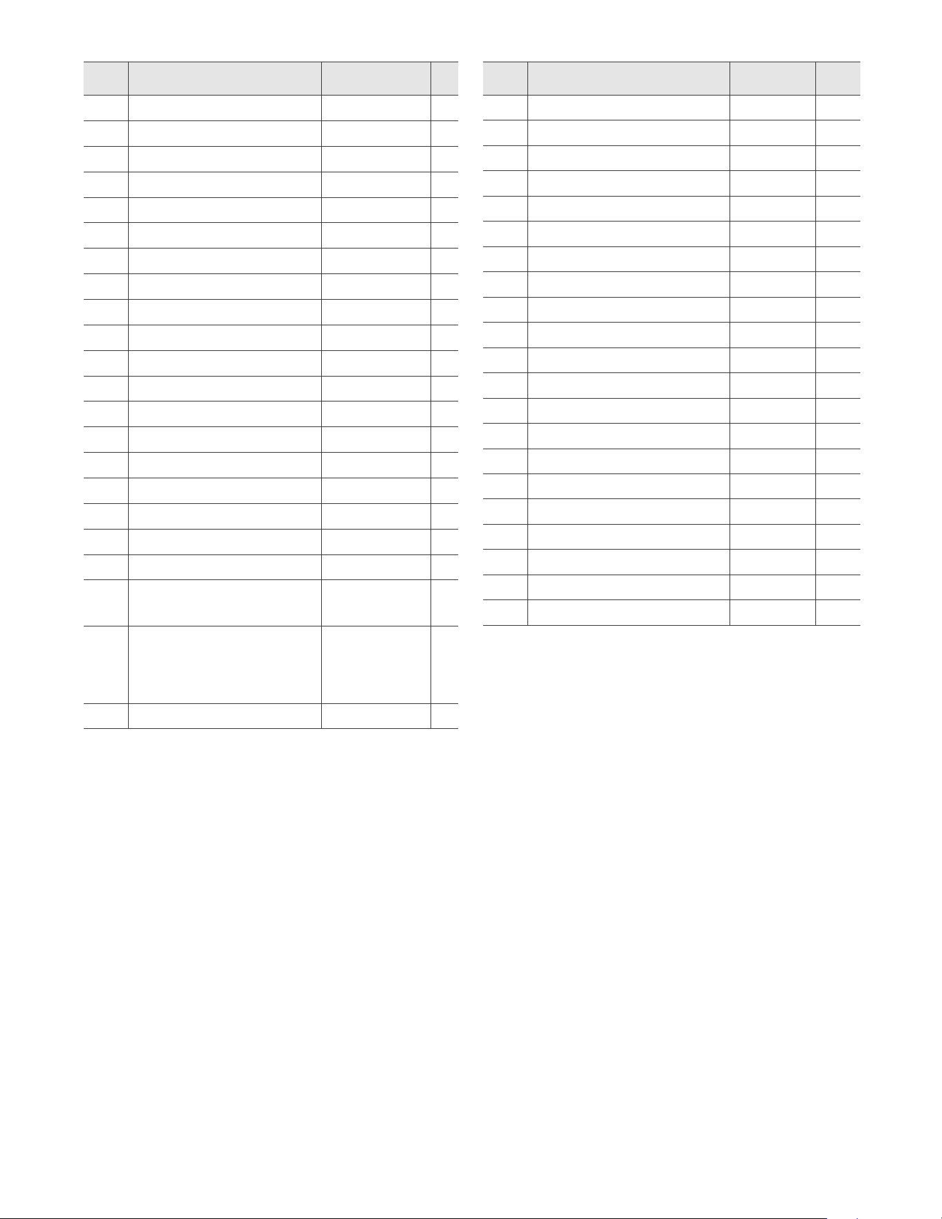
Item Description
1
Blower Connector
1
2
1
3
1
3-1
1
3-2
1
3-3
1
3-4
1
1
1
1
1
4
1
1
1
1
1
9
1
1
11
1
12
Gasket
1
13
1
14
1
Item Description
1
1
1
1
19 1
21 3
22 Water Inlet Pipe 1
23 1
23-1 1
24 1
Circulation Pump 1
Pump Clip 1
1
2
29 Pump Outlet Pipe 1
2
31 Water Inlet Pipe Clip 1
32 2
33 1
34 1
Table 32 – Heat Exhchanger Part
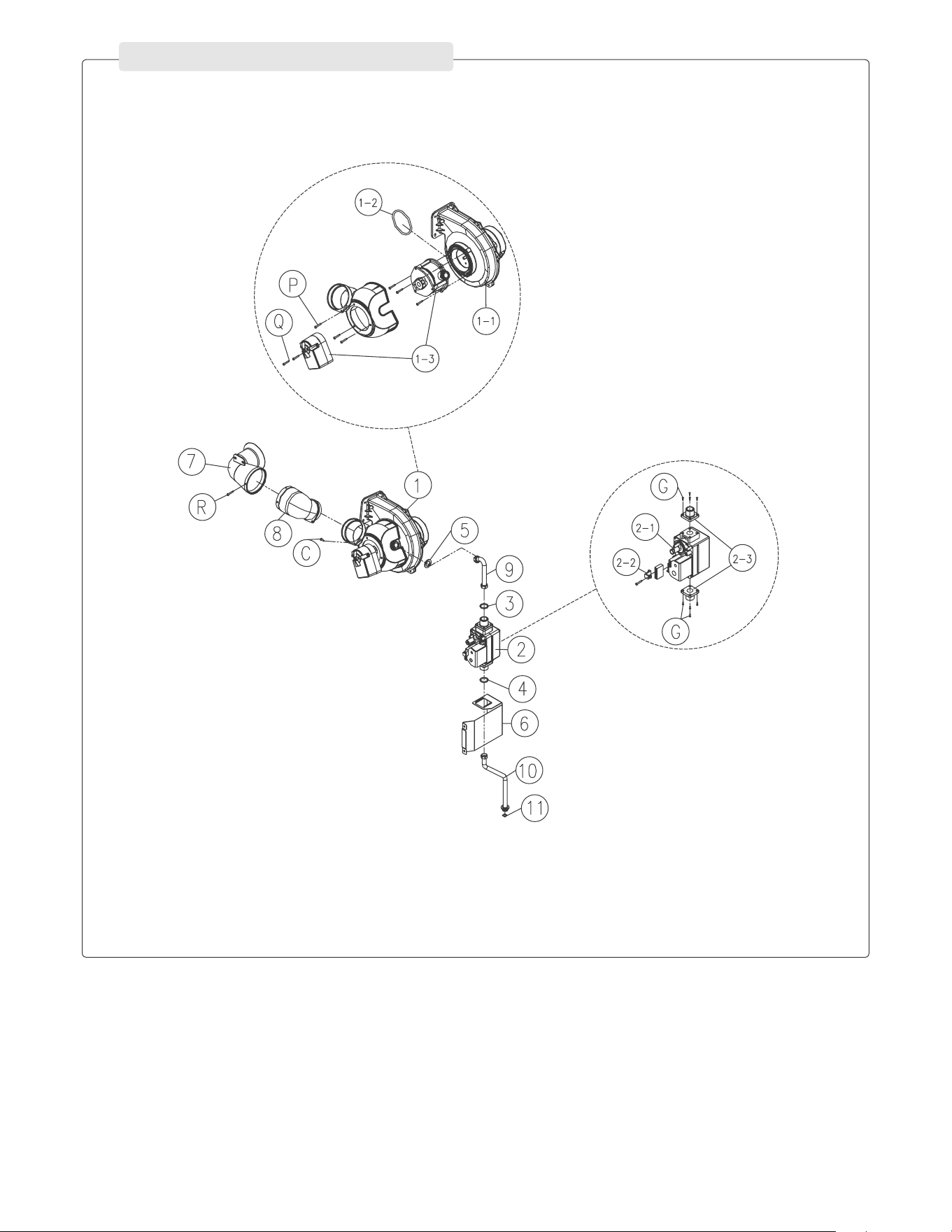
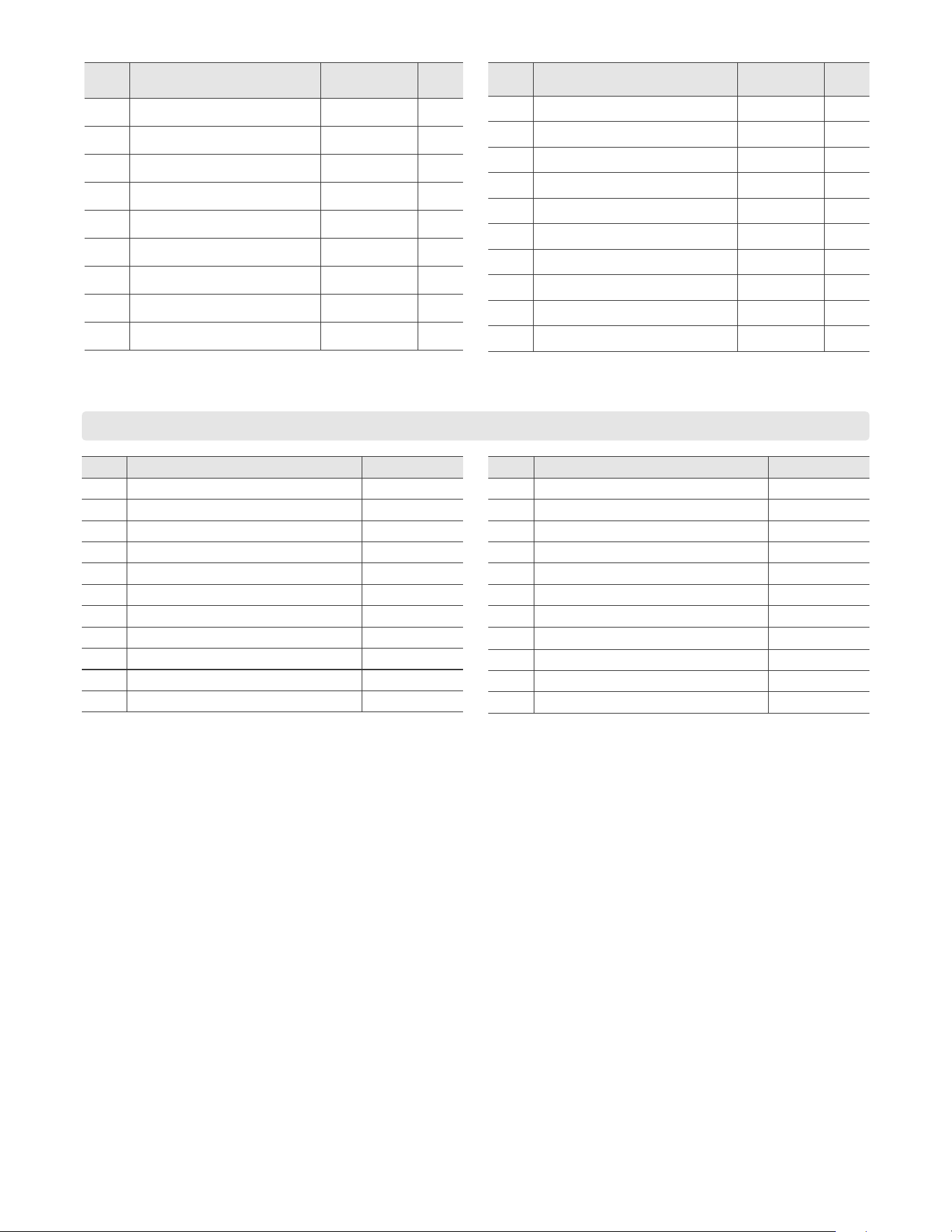
Figure 48 – Fan Motor Part
PART III _ FAN MOTOR PART
Item Description
1
1
1 1
1-1 1
1-2 1
1-3 1
1-3 1
2 1
2-1 1
2-2 1
Item Description
2-3 2
3 1
4 1
1
1
Silencer Body 1
1
9 1
1
11 1
Table 33 – Fan Motor Part
Table 34 – Screw Part
Screw
Item Description
A
B
C
D
M4 x 12
E
G
M4 x 12
I
Item Description
L
M
N
O
P
R
S
U
V
LIGHT OFF ACTIVITIES DATE COMPLETED ________________
Yes No
1) Fill the
heating system
Check all piping and gas connections, verify all are tight
Has the system been cleaned and flushed?
Has the appliance and the system been purged of all air?
Refer to Start-Up Preparation, this manual.
Has the auto air purge feature been used / set? Refer to
Start-Up Preparation, this manual.
Pressurize system (12 – 15 psi) CH ____ PSI
Pressurize system domestic HW
Add water to prime condensate cup
Percentage of glycol in system (0 – 50%) ____ %
Verify proper near appliance piping (Primary/Secondary)
2) Electrical Have the power and control wiring been connected per the
wiring diagram in this manual?
Is the supply voltage 120v and polarity correct?
3) Check gas
pipe
Leak test using locally approved methods (consult
jurisdictional code book)
Has the gas supply line been verified to deliver the required
BTU of the appliance?
Has a union and shut-off valve (no less than ¾” ) been
installed?
Does the gas type match the type indicated on the rating
plate?
Check incoming gas pressure (Max is 12.5" for NG and 13" for LP)
____ in w.c. Static
If necessary, convert the appliance to the proper gas type
Locate the stickers in the appropriate locations on the
appliance
If applicable, have all dip switches been set and verified to
match system requirements?
Verify combustion settings after gas conversion, Carbon
Dioxide
____% CO2 High Fire ____% CO2 Low Fire
Verify combustion settings after gas conversion, Carbon
Monoxide
____ppm
CO
High Fire ____ppm CO Low Fire
What is the “drop” on light off (No more than 1” W.C.)? ____ in w.c. Dynamic
4) Venting Has the appliance been vented with 2" or 3" PVC, CPVC,
Polypropylene, or (AL294C) Stainless for Cat IV
appliances?
Ensure no ABS or PVC Cellular core has been used
Is the vent sloped upward toward the terminal at a rate of ¼”
per ft. or 2% grade?
Have all intake and exhaust joints been properly sealed and
tested?
Are all vent runs properly supported?
Have the termination screens been installed?
Is the vent termination a min of 12” above grade or the
highest anticipated snow level?
Is the total developed vent length including elbows within
the stated max vent length restriction?
5) Condensate
piping / tubing
Is the condensate line piped with the approved materials
listed in this manual?
Does the condensate line have an air inlet at the top/
beginning of the drain? Refer to Install the Condensate
Drain, this manual.
Has the condensate been piped over to a drain, and
checked to be free flowing?
If necessary, has a condensate pump and /or a neutralizer
been installed?
FINAL SIGNED BY TECHNICIAN DATE
START-UP REPORT
Table 35 – Start-Up Report
CO
2
CO
2
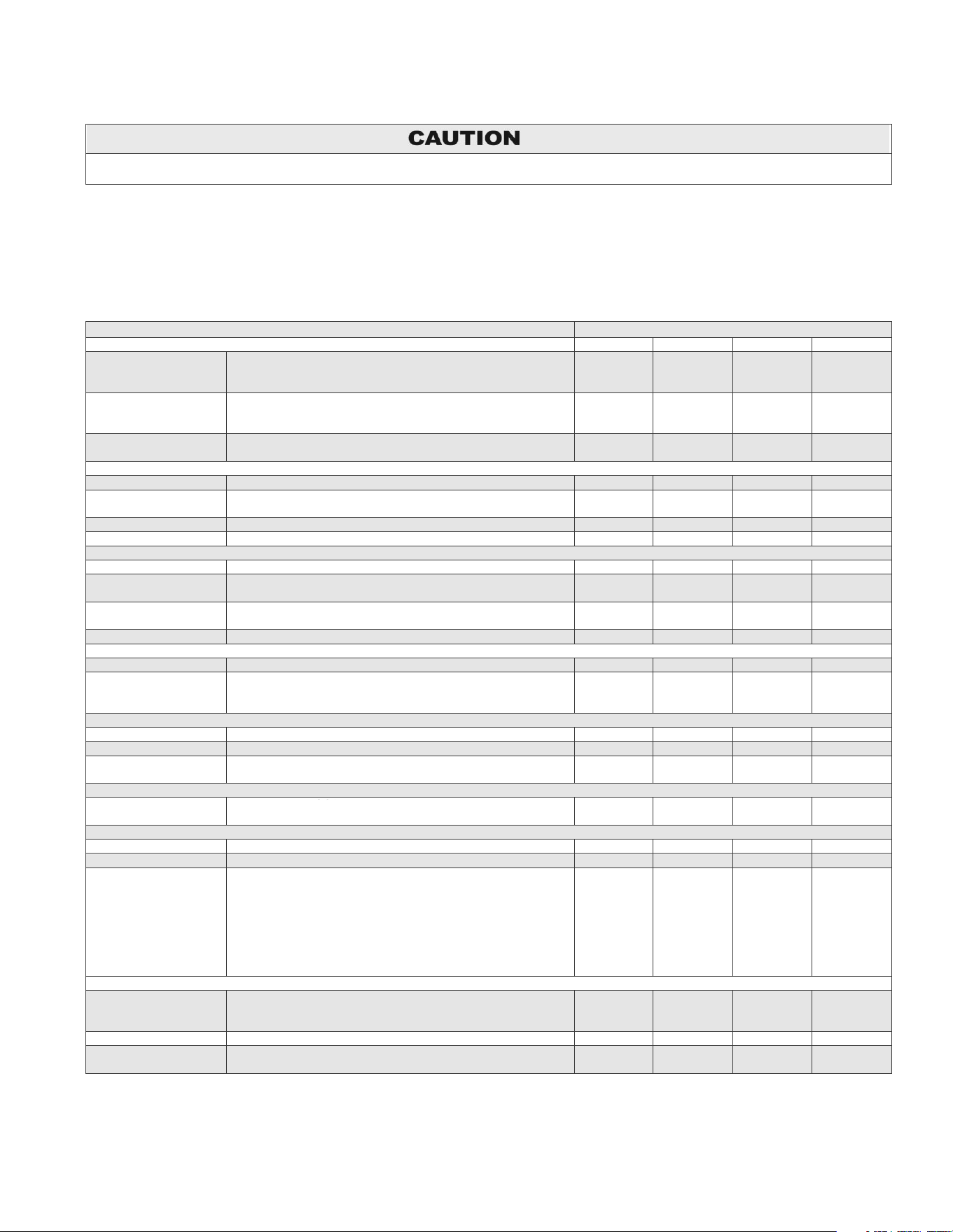
MAINTENANCE REPORT
In unusually dirty or dusty conditions, care must be taken to keep appliance cabinet door in place at all times. Failure to do so VOIDS
WARRANTY!
The appliance requires minimal periodic maintenance under normal conditions. However, in unusually dirty or dusty conditions, periodic
vacuuming of the cover to maintain visibility of the display and indicators is recommended.
Periodic maintenance should be performed once a year by a qualified service technician to ensure that all the equipment is operating
safely and efficiently. The owner should make necessary arrangements with a qualified heating contractor for periodic maintenance of
the appliance. Installer must also inform the owner that the lack of proper care and maintenance of the appliance may result in a
hazardous condition.
INSPECTION ACTIVITIES DATE LAST COMPLETED
PIPING
1
s
t
YEAR 2
n
d
YEAR 3
r
d
YEAR 4
th
YEAR*
Near appliance piping Check appliance and system piping for any sign of leakage.
Leaking pipes could cause property damage. Make sure all
piping is properly supported.
Vent Check condition of all vent pipes and joints. Ensure all vent
piping is properly supported. Check for obstructions exhaust
and intake termination points.
Gas Check Gas piping, test for leaks and signs of aging. Make sure
all pipes are properly supported.
SYSTEM
Visual Do a full visual inspection of all system components.
Functional Test all functions of the system (central heating, water heating,
safeties)
Temperatures Verify safe settings on appliance or Anti-Scald Valve
Temperatures Verify programmed temperature settings
ELECTRICAL
Connections Check wire connections. Make sure they are tight.
Smoke and CO
detector
Verify devices are installed and working properly. Change
batteries if necessary.
Circuit Breakers Check to see that the circuit breaker is clearly labeled. Exercise
circuit breaker.
Switch and Plug Verify ON/OFF switch and convenience plug are both functional
CONDENSATE
Neutralizer Check condensate neutralizer. Replace if necessary.
Condensate hose Disconnect condensate hose. Clean out dirt and re-install.
(NOTE: Verify the flow of condensate, making sure that the
hose is properly connected during final inspection.)
GAS
Pressure Meas
ure incoming gas pressure (Max is 12.5" for NG and 13" for LP)
Pressure Drop Measure drop in pressure on light off (no more than 1” W.C.)
Check gas pipe for
leaks
Check piping for leaks. Verify that all are properly supported.
COMBUSTION
CO/CO2 Levels Check CO and CO2 levels in Exhaust. Record at high and low
fire.
SAFETIES
ECO (Energy Cut Out) Check continuity on Flue ECO. Replace if corroded.
CH AND DHW LOOPS
It is recommended to flush the CH and DHW heat exchangers
annually if water hardness exceeds 12 grains per gallon
(considered extremely hard water). If water hardness falls below
12 grains per gallon it is recommended to flush the heat
exchanger every two to three years.
In addition, it is recommended to clean the CH and DHW inlet
filters annually.
FINAL INSPECTION
Check list Verify that you have completed entire check list. WARNING:
FAILURE TO DO SO COULD RESULT IN SERIOUS INJURY
OR DEATH.
Homeowner Review what you have done with the homeowner.
TECH SIGN OFF
Table 36 – *Continue annual maintenance beyond the 4th year as required.
CO
2

AP18733 REV. 3.2.17
MAINTENANCE NOTES
CUSTOMER INSTALLATION RECORD FORM
IMPORTANT NOTES:
Customer: Please only sign after the installer has reviewed the installation, safety, proper operation and maintenance of the system.
In the case that the system has any problems, please call the installer. If you are unable to make contact, please contact your Sales
Representative.
Customer’s Name:
Installation Address:
Date of Installation:
Installer’s Code/Name:
Product Serial Number(s):
Model Number:
Combustion Setting at Time of Installation:
Comments:
Installer’s Phone Number:
Signed by Installer:
Signed by Customer: