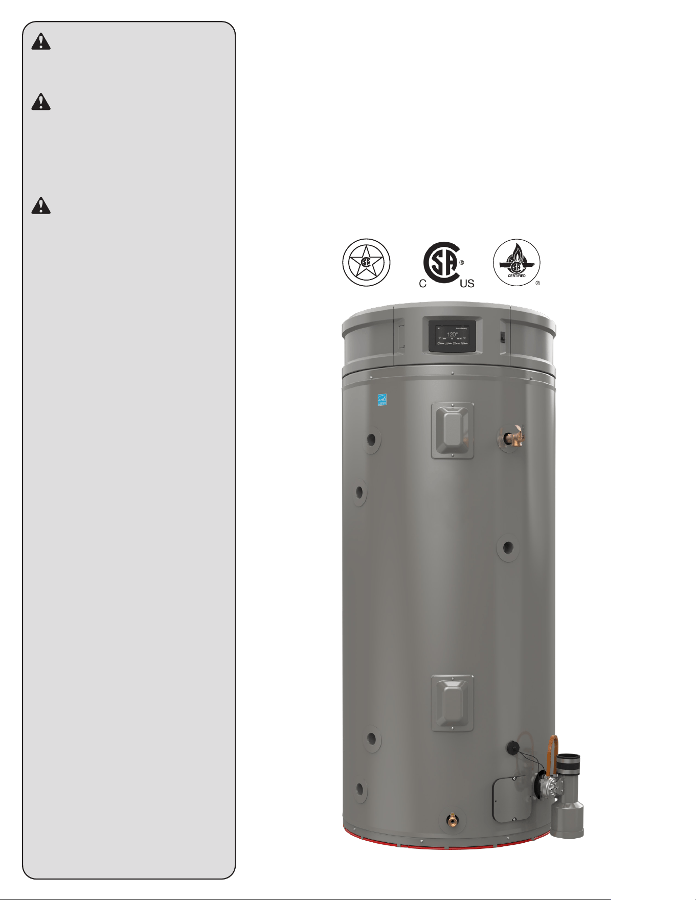
COMMERCIAL HIGH EFFICIENCY COMMERCIAL HIGH EFFICIENCY
WATER HEATERWATER HEATER
USE & CARE MANUALUSE & CARE MANUAL
AP23779
DO NOT destroy this manual.
Please read carefully and keep in a
safe place for future reference
WARNING
If the information in these
instructions is not followed exactly,
a fire or explosion may result
causing property damage, personal
injury or death.
FOR YOUR SAFETY!
• DO NOT store or use gasoline,
other flammable vapors or liquids
or other combustible materials
in the vicinity of this or any other
appliance. Doing so may result in
a explosion or fire.
-WHAT TO DO IF YOU SMELL GAS
• DO NOT try to light any appliance.
• DO NOT touch any electrical
switch.
• DO NOT use any phone in your
home.
• Immediately call your gas
supplier from a neighbor's phone.
And follow the gas supplier's
instructions.
• If you cannot reach your gas
supplier, call the fire department.
• DO NOT return to your home until
authorized by the gas supplier or
fire department.
-ALWAYS REFER TO THIS MANUAL
• Installation and service must be
performed by a qualified installer,
service agency, or gas supplier.
D
E
S
I
G
N
C
E
R
T
I
F
I
E
D
®
Important Safety Information
General Safety Precautions ��������������������������������������������������� 2–5
Product Information
Components Diagram �����������������������������������������������������������������6
Installation
Location ��������������������������������������������������������������������������������������7
Thermal Expansion ��������������������������������������������������������������������������������������8
Water Connections ���������������������������������������������������������������������������������������8
To Fill the Water Heater �������������������������������������������������������������������������������8
Gas Supply ����������������������������������������������������������������������������������������������������9
Leak Testing �������������������������������������������������������������������������������������������������� 9
Condensate ���������������������������������������������������������������������������������������������������9
High Altitude ������������������������������������������������������������������������������������������������10
Wiring ����������������������������������������������������������������������������������������������������������10
Typical Installation ��������������������������������������������������������������������������������������11
Space Heating Connections ����������������������������������������������������������������������12
Venting and Combustion Air Inlet ���������������������������������������������������� 13 - 31
Check List ����������������������������������������������������������������������������������������������������32
Operation
Lighting Instructions ����������������������������������������������������������������������������������33
Safety Precautions �������������������������������������������������������������������������������������34
User Interface
Start Up ����������������������������������������������������������������������������������� 35
Temperature Adjustment ����������������������������������������������������������35
Schedule Settings���������������������������������������������������������������������36
Time/Date Settings �������������������������������������������������������������������36
WiFi Status �������������������������������������������������������������������������������37
Alarms and Service Alerts ��������������������������������������������������������38
Maintenance
Routine Preventive Maintenance ��������������������������������������������� 39
Seasonal Operation ������������������������������������������������������������������39
Venting System ������������������������������������������������������������������������� 39
Before You Call For Service
Troubleshooting Tips ���������������������������������������������������������� 40, 41
Error Codes ������������������������������������������������������������������������ 42- 47
Replacement Parts
Instructions For Placing a Parts Order 48
Wiring and Schematic Diagrams ......................................49
How to Obtain Service Assistance ....................................52
2
CONTENTS
Your safety and the safety of others are very important.
There are many important safety messages in this manual
and on your appliance. Always read and follow all safety
messages.
This is the safety alert symbol. Recognize this
symbol as an indication of importan safety
information! This symbol alerts you to safety
hazards that could result in physical harm or
death.
All safety messages will follow the safety alert symbol and
either the word “DANGER,” “WARNING,” “CAUTION,” or
“NOTICE.”
These words mean:
READ ALL SAFETY INFORMATION
FOR YOUR RECORDS:
Write the model and serial numbers here:
You can find them on a label on the appliance.
Staple sales slip or cancelled check here.
Proof of the original purchase date is needed to obtain service
under the warranty.
DANGER:
NOTICE:
!
CAUTION:
!
WARNING:
An imminently hazardous
situation that will result in
death or serious injury.
A potentially hazardous
situation that can result in
death or serious injury and/or
damage to property.
A potentially hazardous
situation that may result in
minor or moderate injury.
Attention is called to observe a
specified procedure or maintain
a specific condition.
!
3
GENERAL SAFETY PRECAUTIONS
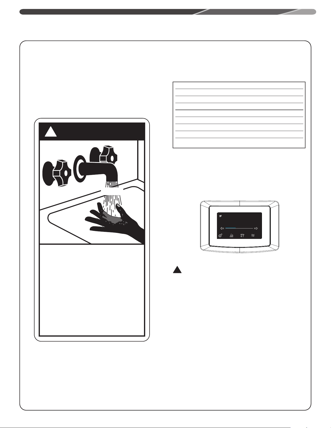
To meet commercial water use needs, the temperature on
this water heater is adjustable up to 185°F (85°C). However,
water temperatures over 125°F (52° C) can cause severe
burns instantly or death from scalds. This is the preferred
starting point for setting the control for supplying general
purpose hot water.
Safety and energy conservation are factors to be considered
when setting the water temperature. The most energy
efficient operation will result when the temperature setting is
the lowest value that satisfies the needs consistent with the
application.
Maximum water temperatures occur just after burner
has shut off. To find the temperature of the hot water
being delivered, turn on a hot water faucet, and place
a thermometer in the hot water stream, and read the
thermometer.
The following chart details the relationship of water
temperature and time to scald injury and may be used as
a guide in determining the safest water temperature for
your applications.
The temperature of the water in the heater can be regulated
by setting the temperature on the display (see "User
Interface" section). To comply with safety regulations the
water heater temperature was adjusted to lowest setting
before the water heater was shipped from the factory. The
illustration information on "User Interface" section shows the
display and how to adjust the water temperature.
DANGER:
Hotter water increases the potential for hot water SCALDS.
NOTICE:
Mixing valves are recommended for reducing point of
use water temperature by mixing hot and cold water in
branch water lines. It is recommended that a mixing valve
complying with the Standard for Temperature Actuated
Mixing Valves for Hot Water Distribution Systems, ASSE
1017 be installed. See Water Connections for more details.
For additional information, contact a licensed plumber or
the local plumbing authority.
DANGER
!
HOT
BURN
Water temperature over 125°F (52°C)
can cause severe burns instantly or
death from scalds.
Children, disabled and elderly persons
are at greatest risk of being scalded.
See instructions manual before setting
temperature of water heater.
Feel water Before bathing or showering.
Temperature limiting valves are
available, see manual.
Water Temperature Time to Produce Serious Burn
120° F (49°C) More than 5 minutes
125° F (52°C) 1
1
/
2
to 2 minutes
130° F (54°C) About 30 seconds
135° F (57°C) About 10 seconds
140° F (60°C) Less than 5 seconds
145° F (63°C) Less than 3 seconds
150° F (66°C) About 1
1
/
2
seconds
155° F (68°C) About 1 second
Table courtesy of Shriners Burn Institute
TIME / TEMPERATURE RELATIONSHIPS IN SCALDS
See Section "User Interface" for setting the temperature�
!
Status: Standby
StatusSettings
warm hot very hot
Disable
120°
Service
4
GENERAL SAFETY PRECAUTIONS
Be sure to read and understand the entire Use and Care Manual before attempting to install or operate this water heater. It may
save you time and money. Pay particular attention to the Safety Instructions. Failure to follow these warnings could result in serious
bodily injury or death. Should you have problems understanding the instructions in this manual, or have any questions, STOP, and
get help from a qualified service technician, or the local gas utility.
Venting:
!
DANGER:
Failure to properly vent the water heater to the outdoors as
outlined in the "Venting and Combustion Air Inlet" section of
this manual can result in unsafe operation of the water heater.
To avoid the risk of fire, explosion, or asphyxiation from carbon
monoxide, never operate this water heater unless it is properly
vented and has adequate air supply for proper operation. Be sure
to inspect the Venting and Combustion Air Inlet section for proper
installation at initial start-up and, at least, annually, thereafter.
Refer to the "Maintenance" section of this manual for more
information regarding vent system inspections.
!
!
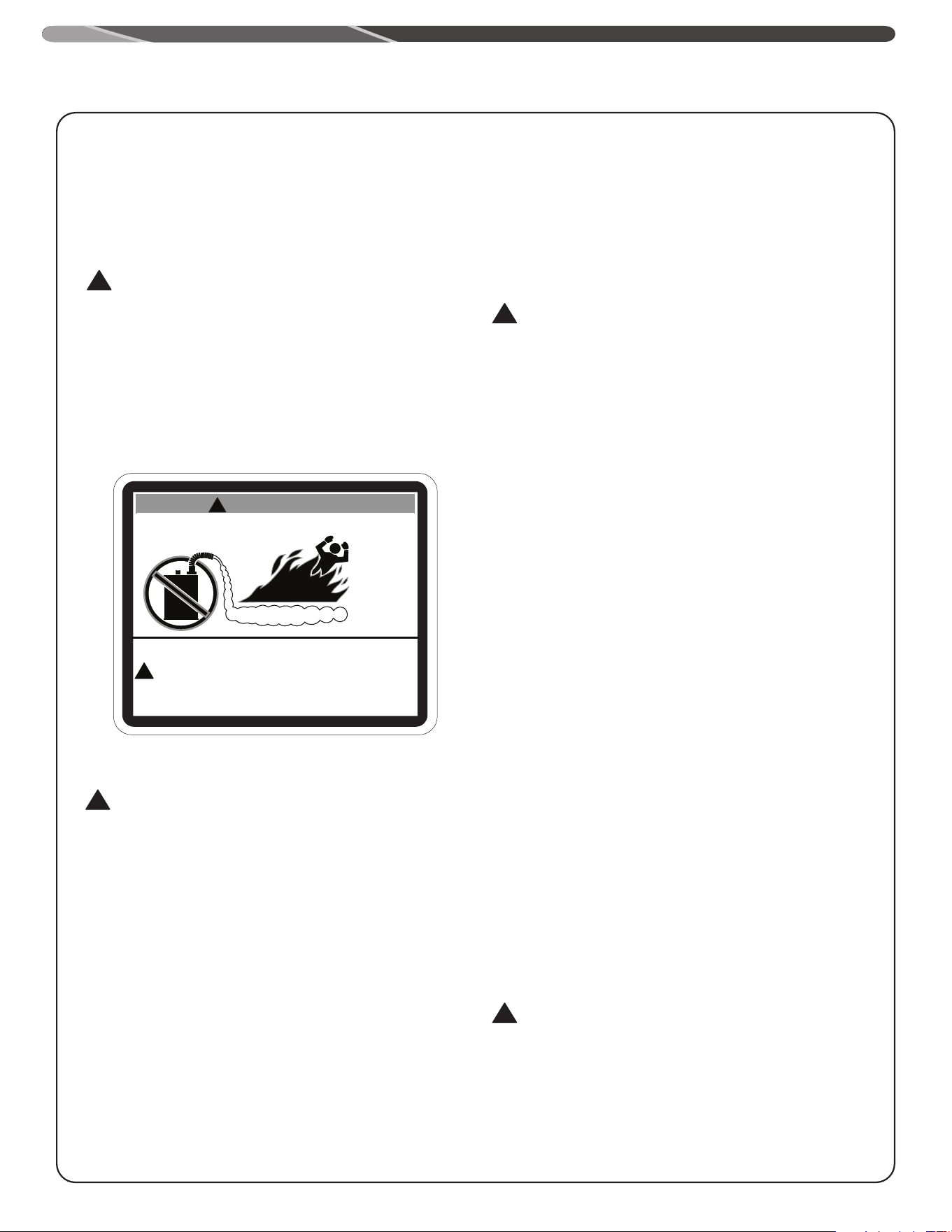
FLAMMABLES
Flammable Vapors
FIRE AND EXPLOSION HAZARD
Can result in serious injury or death.
Do not store or use gasoline or other flammable vapors and liquids
in the vicinity of this or any other appliance. Storage or use of gasoline
or other flammable vapors or liquids in the vicinity of this or any other
appliance can result in serious injury or death.
W ARNING
Flammable Materials:
!
WARNING:
Gasoline, as well as other flammable materials and liquids
(which include but are not limited to adhesives, solvents, paint
thinners, etc.), and the vapors they produce are extremely
dangerous. DO NOT handle, use, or store gasoline or other
flammable or combustible materials anywhere near or in the
vicinity of a water heater or any other appliance. Be sure to
read and follow the warning label pictured below and other
labels on the water heater and in this manual. Failure to do so
can result in property damage, bodily injury, or death.
Natural Gas and Lique-
fied Petroleum Safety
!
DANGER:
LIQUEFIED PETROLEUM MODELS — Propane (LP) gas, must be
used with great caution.
• It is heavier than air and will collect first in lower areas
making it hard to detect at nose level.
• Make sure to look and smell for LP leaks before
attempting ignition of the water heater. Use a soapy
solution to check all gas fittings and connections.
Bubbling at a connection indicates a leak that must be
corrected.
• When smelling to detect an LP leak, be sure to sniff near
the floor too.
• Gas detectors are recommended in LP applications
and their installation should be in accordance with the
manufacturer's recommendations and local laws, rules,
regulations, or customs.
• It is recommended that more than one method be used
to detect leaks in LP applications.
IF LP GAS IS PRESENT OR SUSPECTED:
• DO NOT attempt to find the cause yourself;
• DO NOT try to light any appliance;
• DO NOT touch any electrical switch;
• DO NOT use any phone in your building.
• Leave the building immediately and make sure your
family and pets leave also.
• Leave the doors open for ventilation and contact the
gas supplier, a qualified service agency or the fire
department.
• Stay away from the house (or building) until the service
call has been made, the leak is corrected and a qualified
agency has determined the area to be safe.
!
WARNING:
Both LP and natural gas have an odorant added to help
detection. Some people may not physically be able to smell or
recognize this odorant. If unsure or unfamiliar about the smell
associated with LP or natural gas, ask the gas supplier. Other
conditions, such as "Odorant Fade", which causes the odorant
to "fade" or diminish in intensity can also hide or camouflage
a gas leak.
5
GENERAL SAFETY PRECAUTIONS
!
DANGER:
Water heaters utilizing Liquefied Petroleum gas (LP) are
different from natural gas models. A natural gas heater will
not function safely on LP gas and vice versa. No attempt
should ever be made to convert a heater from natural gas to
LP gas. To avoid possible equipment damage, personal injury
or fire: DO NOT connect this water heater to a fuel type not in
accordance with the unit's data plate. Propane for propane
units; natural gas for natural gas units. These units are not
certified for any other type fuel.
!
WARNING:
LP appliances should not be installed below-grade (for
example, in a basement) if such installation is prohibited by
federal, state, or local laws, rules, regulations or
customs.
Electrical Safety
DANGER:
• Shock Hazard – Make sure the electrical power to the
water heater is off to avoid electric shock that will result
in death or serious personal injury.
WARNINGS:
• For your safety, the information in this manual must
be followed to minimize the risk of fire, explosion, or
electric shock that can result in death, personal injury,
and/or property damage.
• Field wiring connections and electrical grounding must
comply with local codes or, in the absence of local
codes, with the latest edition of the National Electrical
Code, ANSI/NFPA 70, or in Canada, Canadian Electrical
Code, CAN/CSA C22.1, Part 1.
CAUTIONS:
• Label all wires prior to disconnecting for service. Wiring
errors can cause dangerous and improper operation.
Verify correct operation after servicing.\
• For your safety, burner inspection and cleaning should
be performed only by qualified service personnel.
• Make certain the power to the water heater is OFF
before removing the unit cover panel. Exposed electrical
components and moving parts can cause personal
injuries.
• For your safety, DO NOT attempt repair of electrical
wiring, gas piping, remote control, burners, vent
connectors, or other safety devices. Refer repairs to
qualified service personnel.
FOR INSTALLATIONS IN THE
STATE OF CALIFORNIA
California Law requires that all new and replacement water
heaters, and all existing commercial water heaters, must be
braced, anchored, or strapped to resist falling or horizontal
displacement due to earthquake motion. At a minimum,
any water heater shall be secured in accordance with the
California Plumbing Code, or modifications made thereto
by a city, county, or city and county pursuant to Section
17958.5. Generic instructions for California titled “Guidelines
for Earthquake Bracing Commercial Water Heaters” can be
obtained by:
• Writing the California, Department of General Services,
Division of State Architect, 1102 Q Street, Suite 5100,
Sacramento, CA 95814
• Calling (916) 445-8100
• Following web address:
https://www�dgs�ca�gov/-/media/Divisions/DSA/Publications/
gas_shutoff/waterheaterbracing
Inspect Shipment
Carefully inspect the water heater for damage before
proceeding with the installation. Of specific interest should
be combustion air-inlet piping assembly, exhaust-tee, or
damage to blower-valve assembly. If you find damage,
DO NOT install or attempt any repair to the water heater.
Contact the manufacturer as detailed under "HOW TO OBTAIN
ASSISTANCE".
6
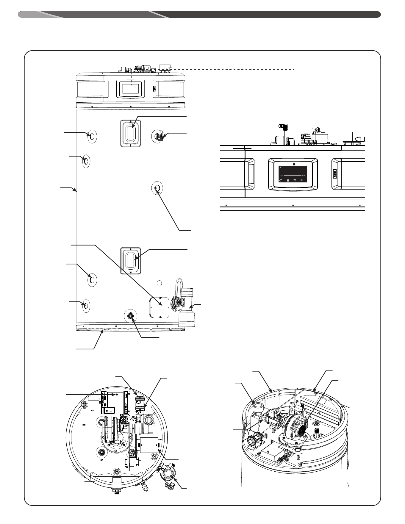
COMPONENTS DIAGRAM
Jacket
Anode
Anode
Anode
Leak Sensor
Side Outlet
Side Inlet
Temperature
and Pressure
Relief Valve
Upper
Thermistor
Drain Valve
Leak Sensor
Exhaust
Tee Assy
Pressure
Switch
(Intake)
Front Panel
Assy
Blower
Side Panel
Air Intake
Pressure Switch
Proof of Fan
Ignition Control
Exhaust
Tee Assy
Transformer Box
Gas Inlet
Lower
Thermistor
Front View
Touch Display
Top View Back Iso View
Status: Standby
StatusSettings
warm hot very hot
Disable
120°
Service
7
INSTALLATION
Location
This water heater must be installed in accordance with these instructions, local codes, utility company requirements, and/or in
the absence of local codes, use the latest edition of the American National Standard/National Fuel Gas Code for US and CAN/CSA
B149 - Natural Gas and Propane Installation Code for Canada. A copy can be purchased from the American Gas Association, 400N.
Capitol Street NW, Washington, DC 20001 as ANSI standard C223.1 or National Fire Protection Association, 1 Batterymarch Park,
Quincy, MA 02269 as booklet NFPA 54. for US and Canadian Standards Association, 5060 Spectrum Way, Mississauga, Ontario
L4W5N6 for Canada.
The water heater should not be located in an area where leakage
from the tank or connections will result in damage to the area
adjacent to the heater or to lower floors of the structure.
When such areas cannot be avoided it is recommended that a
suitable drain pan, adequately drained, must be installed under
the water heater.
The auxiliary drain pan installation MUST conform with local
codes.
The water heater must be positioned in the drain pan as shown.
Ensure that the condensate-tee is located inside the drain pan.
The recommended minimum drain pan sizes are 28" diameter for
50Gal and 32" diameter for 75Gal water heaters
Drain pan kits are available from the store where the water
heater was purchased, or any water heater distributor.
Make certain the floor underneath the water heater is strong
enough to sufficiently support the weight of the water heater
once it is filled with water.
This gas-fired water heater or any other appliance should not
be installed in a space where liquids which give off flammable
vapors are to be used or stored. Such liquids include gasoline,
LP gas (butane or propane), paint or adhesives, thinners, solvents
and/or combustible removers.
WARNING:
Because of natural air movement in a room or other
enclosed space, flammable vapors can be carried some
distance from where liquids which give off flammable vapors
are to be used or stored. The open flame of the water heater’s
main burner can ignite these vapors creating a shut down
condition which will not allow the water heater to ignite.
Rheem Water Heating FVIR certified gas water heaters can
be installed on a residential garage floor without the use of
an 18 in. (46 cm.) stand in accordance with the National Fuel
Gas Code, ANSI Z223.1/NFPA 54, unless otherwise directed by
State and Local code requirements. The water heater must be
located so it is not subject to physical damage, for example, by
moving vehicles, area flooding, etc.
IMPORTANT: DO NOT install the water heater in a location where
it may be subjected to ambient temperatures exceeding 125°F
(52°C).
• The water heater should be installed so as to minimize the
length of plastic vent and combustion air-inlet pipe and the
number of vent and combustion air-inlet connection fittings
required.
• See Vent and Combustion Air-Inlet Section for vent system
requirements.
• Hot water lines should be insulated to conserve water and
energy.
• Protect the water heater and water lines from exposure to
freezing temperatures.
• DO NOT install this water heater outdoors.
• Minimum clearances from combustible construction:
Front Sides Rear Top
5 In.
(12.7 cm)
0 In.
(0 cm)
0 In.
(0 cm)
15 In.
(30.5 cm)
The Exhaust Tee located on the right front of the unit will require additional side
clearance of approximately 2.75" from the water heater.
"Front" Clearance dimension is measured from the water heater
jacket to the closet door.
"Top" clearance dimension is measured from the jacket top of
the water heater to the ceiling.
NOTICE:
For proper operation and maintenance, a minimum
clearance of 1.5 inches (3.8 cm) must be provided from
the combination temperature and pressure relief valve to
any wall or object.
WARNING:
Combustible construction refers to adjacent walls and
ceilings and should not be confused with combustible or
flammable products and materials. Combustible and/or
flammable products and materials should never be stored in
the vicinity of this or any gas appliance.
DRAIN PAN
8
INSTALLATION
If the water heater is to be installed directly on carpeting,
the water heater shall be installed on a metal or wood
panel extending beyond the full width and depth of the
water heater by at least 3 in. (7.6 cm) in all directions or, if
the water heater is to be installed in an alcove or closet, the
entire floor must be covered by a wood or metal panel.
CORROSIVE ATMOSPHERES
The air in beauty shops, dry cleaning establishments,
photo processing labs, and storage areas for liquid and
powdered bleaches or swimming pool chemicals often
contain halogenated hydrocarbons.
An air supply containing halogenated hydrocarbons may
be safe to breathe, but when it passes through a gas
flame corrosive elements are released that will shorten
the life of any gas burning appliance.
Propellants from common spray cans or gas leaks from
A/C and refrigeration equipment are highly corrosive after
passing through a flame.
The water heater warranty is voided when failure of the
heater is due to operation in a corrosive atmosphere.
THERMAL EXPANSION
Determine if a check valve exists in the inlet water line.
It may have been installed in the cold water line as a
separate back flow preventer, or it may be part of a
pressure reducing valve, water meter or water softener.
A check valve located in the cold water inlet line can
cause what is referred to as a ”closed water system”.
A cold water inlet line with no check valve or back flow
prevention device is referred to as an ”open” water
system.
As water is heated, it expands in volume and creates an
increase in the pressure within the water system. This
action is referred to as ”thermal expansion”. In an ”open”
water system, expanding water, which exceeds the
capacity of the water heater, flows back into the city main
where the pressure is easily dissipated.
A ”closed water system”, however, prevents the
expanding water from flowing back into the main supply
line and the result of ”thermal expansion” can create
a rapid, and dangerous pressure increase in the water
heater and system piping. This rapid pressure increase
can quickly reach the safety setting of the relief valve,
causing it to operate during each heating cycle. Thermal
expansion, and the resulting rapid, repeated expansion
and contraction of components in the water heater and
piping system can cause premature failure of the relief
valve and possibly the heater itself. Replacing the relief
valve will not correct the problem!
The suggested method of controlling thermal expansion is
to install an expansion tank in the cold water line between
the water heater and the check valve. The expansion tank
is designed with an air cushion built in that compresses
as the system pressure increases, thereby relieving the
over pressure condition and eliminating the repeated
operation of the relief valve. Other methods of controlling
thermal expansion are also available. Contact your installing
contractor, water supplier, or plumbing inspector for
additional information regarding this subject.
WATER CONNECTIONS
Refer to illustration on page 12 for suggested typical
installation. The installation of unions or flexible connectors
is recommended on the hot and cold water connections
so that the water heater may be easily disconnected for
servicing if necessary. If flexible water connections are
used, they must comply with the standard for flexible Water
Connectors, ASME A112.18.6/CSA-B125.6. The HOT and
COLD water connections are clearly marked on the water
heater. Install a shutoff valve in the cold water line near the
water heater.
IMPORTANT
All models are equipped with front and side panels, it is
recommended that the hot and cold water piping have a
minimum vertical height of 10 inches (25.4 cm) from the
top of the water heater before transitioning into any elbow.
This vertical height is needed in order to provide adequate
clearance for Side Panel installation and removal.
To gain access to the hot and cold water connections
the side panels need to be removed. The side panels are
secured on the top of the water heater with fastening
pegs (see illustration). Pull the side panels either
outwards or upwards to release panels from pegs.
RELIEF VALVE
The pressure rating of the relief valve must not exceed 150
psi (1,034 kPa), the maximum working pressure of the water
heater as marked on the rating plate.
The Btu/h rating of the relief valve must equal or exceed the
Btu/h input of the water heater as marked on its rating plate.
Position the outlet of the relief valve above a suitable open
drain to eliminate potential water damage. Piping used
should be of a type approved for hot water distribution.
The discharge line must be no smaller than the outlet
of the valve and must pitch downward from the valve to
allow complete drainage (by gravity) of the relief valve and
discharge line.
The end of the discharge line should not be threaded or
concealed and should be protected from freezing. No valve
of any type, restriction, or reducer coupling should be
installed in the discharge line.
TO FILL THE WATER HEATER
Make certain that the drain valve is closed, then open the
shut-off valve in the cold water supply line.
Open each hot water faucet slowly to allow the air to vent
from the water heater and piping.
A steady flow of water from the hot water faucet(s) indicates
a full water heater.
9
GAS SUPPLY
The inlet gas pressure to the water heater must not
exceed 10.5" wc (2.6 kPa) for Natural gas and 13.0" wc
(3.2 kPa) for L.P. gas. The minimum inlet gas pressure
(with main burner on) is shown on the rating plate. Check
to see if high or low gas pressure is present and then
contact the gas company for correction.
The branch gas supply line to the water heater should
be clean properly sized steel pipe or other approved gas
piping material.
A union or ANSI design certified semirigid or flexible gas
appliance connector should be installed in the gas line
close to the water heater. The National Fuel Gas Code
(NFGC) mandates a manual gas shut off valve: See (NFCG)
for complete instructions.
If flexible connectors are used, the maximum length shall
not exceed 36 in. and must meet the requirements in ANSI
Z21.24/CSA 6.10 - Connectors for Gas Appliances.
Compound used on the threaded joints of the gas piping
must be of the type resistant to the action of LP gas. Use
compound sparingly on male threads only.
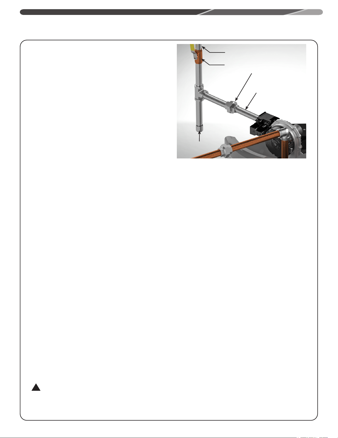
Where a sediment trap is not incorporated as part of the
appliance, a sediment trap shall be installed downstream
of the equipment shutoff valve as close to the inlet of
the appliance as practical at the time of the appliance
installation. The sediment trap shall be either a tee fitting
with a capped nipple in the bottom outlet or other device
recognized as an effective sediment trap. See Figure.
DO NOT use excessive force (20Ft. Lbs.) in tightening the
pipe joint at the gas control (thermostat) inlet, particularly
if teflon pipe compound is used, as the valve body may be
damaged.
For purposes of input adjustment, the minimum inlet
gas pressure (with main burner on) is shown on the
water heater rating plate. If high or low gas pressure are
present, contact your gas supplier for correction.
A ground joint union and manual shutoff valve should be
installed in the gas line near the water heater so that the
burner assembly may be easily removed. The shut-off
valve must be readily accessible for turning on or off.
LEAK TESTING
The water heater and its gas connections MUST be leak
tested at normal operating pressure before it is placed in
operation. Turn ON the manual gas shut-off valve near the
water heater. Use a soapy water solution to test for gas
leaks at all connections and fittings. Bubbles indicate a
gas leak that must be corrected. The water heater factory
connections to the gas valve should also be leak tested
after placing the water heater in operation.
!
WARNING:
NEVER use open flame to test for gas leaks, as bodily
injury or property damage could result.
INSTALLATION
PRESSURE TESTING THE GAS SUPPLY SYSTEM
The water heater and its individual gas shut-off valve
MUST be disconnected from the gas supply piping
system during any high pressure testing of that system at
pressures in excess of 1/2 psi (14” WC. 3.5 kPa).
The water heater MUST be isolated from the gas piping
system by closing the manual gas shut-off valve during
any pressure testing of the gas supply piping at pressures
equal to or less than 1/2 psi (14” WC / 3.5 kPa).
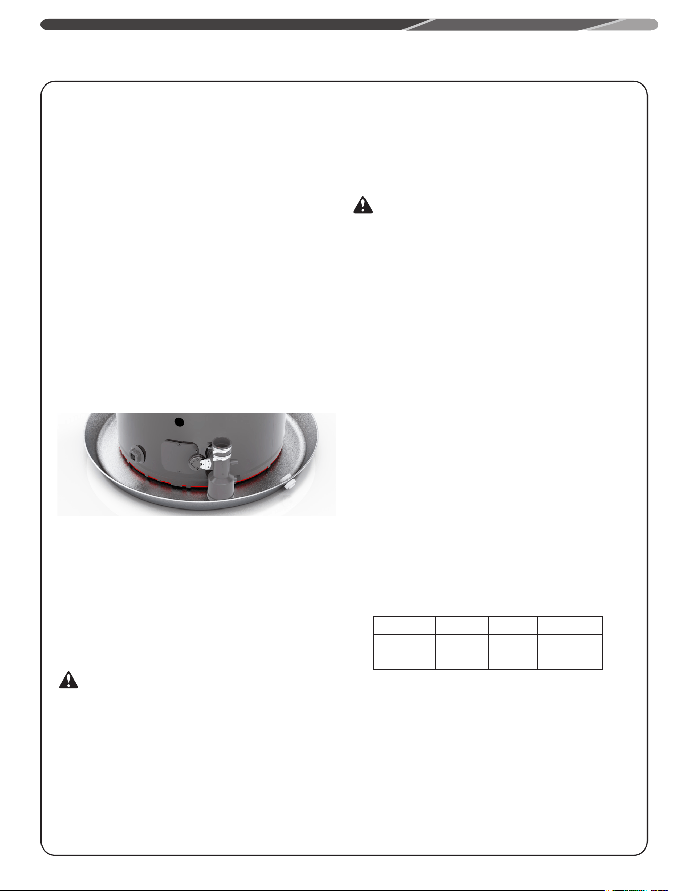
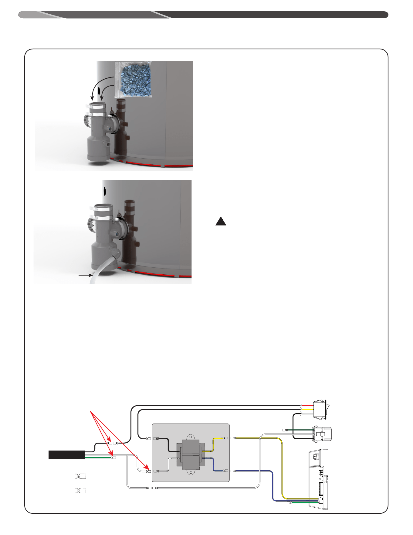
CONDENSATE
The exhaust elbow/condensate trap is shipped pre-installed
with the heater. Pour the neutralizer into the exhaust tee
before vent pipe installation. Make sure that the neutralizer is
at the bottom as shown in the figure on next page.
This is a condensing high efficiency appliance and has a
condensate removal system. The exhaust tee incorporates
a condensate trap and must be filled with water before
operating the water heater. Pour about 1 cup of water into
the exhaust tee.
This water heater generates condensate and requires a drain
to be located in close proximity to allow condensate to drain
safely. The drain line and fittings should be installed per
installation instructions.
Be sure the condensate runs freely to the drain and does not
accumulate in the condensate trap or the condensate line. In
cold climates, precautions may need to be taken to ensure
that the condensate drain lines do not freeze. A water proof
heat tape may be used to prevent freezing of condensate
lines.
• Condensate is mildly acidic and should be collected and
disposed per local codes. Certain local codes require
condensate to be neutralized before it is disposed. This
water heater comes with a pre-packaged neutralizer bag.
Pour the neutralizer in the exhaust-tee prior to installing
vent pipes. Make sure the neutralizer is at the bottom of the
exhaust-tee.
To Gas Supply
Manual Gas Shut Off
Gas Pipe to Gas Valve
Sediment
Trap
Union
10
• Use only PVC, CPVC pipe or flexible tubing suitable for use
with flue condensate as drain line. If flexible tubing is used
ensure that there are no bends or twists and has gradual
slope to condensate drain.
• The drain line (along its entire length) must be at least the
same diameter as the drain of the condensate trap (1/2”).
• The drain line must be short as possible and have a
downward slope towards the condensate drain. If suitable
slope is not provided, the drain line can get blocked and will
cause improper operation of the water heater. If a downward
slope cannot be provided, a condensate pump should be used
to pump condensate to a suitable drain.
• The end of the drain line should be open to the atmosphere.
The end should not be under water.
• DO NOT connect the drain line directly to the sewer drain.
• DO NOT connect the drain line with drains from other
appliances.
• DO NOT drain condensate into the water heater drain pan.
• DO NOT drain condensate over public way, walkway or other
areas where it will create slippery condition, which could lead
to personal injury.
HIGH ALTITUDE
Input rating of this water heater is based on sea level
operation. At higher elevations the actual input rate may
be lower than the value listed on the rating label due to the
derating of Natural Gas and LP Gas.
!
WARNING:
Failure to install a water heater suitable for the altitude
at the location it is intended to serve, can result in
improper operation of the appliance resulting in property
damage and/or producing carbon monoxide gas, which
could result in personal injury, or death.
WIRING
A Correct polarity 120V 50/60 Hz power supply with
suitable disconnect means, must be connected to the
black and white leads provided. The maximum current
draw by these models is 7 Amps. The water heater, when
installed, must be electrically grounded in accordance
with local codes or, in the absence of local codes, with
the National Electrical Code, ANSI/NFPA 70 in the United
States, or CSA C22.1 Electrical Code, in Canada. Improper
grounding or polarity may result in abnormal operation of
the heater.
INSTALLATION
CONDENSATE
NEUTRALIZER
CONDENSATE
DRAIN
To open drain
Transformer
(120V / 60Hz)
F
F
F
F
M
M
M
M
F
To Ground Block
3
2
1
3
2
1
3
2
1
F
To Ground Block
To Ground Block
F
F
M
F
M
Power Cord
Display Rocker Switch
on the front display
C1
Blower Power Connector
C2
Ignition Control Power
Connector
C3
M
F
2-520263-2
Disconnect
2-520102-2
Disconnect
Transformer
(120V / 60Hz)
F
F
F
F
M
M
M
M
F
To Ground Block
3
2
1
3
2
1
3
2
1
F
To Ground Block
To Ground Block
F
F
M
F
M
Power Cord
Display Rocker Switch
on the front display
C1
Blower Power Connector
C2
Ignition Control Power
Connector
C3
M
F
2-520263-2
Disconnect
2-520102-2
Disconnect
For disconnects can be cut o and replaced
with wire nuts to connect the leads to the
power cable from the electrical junction
box if necessary.
11
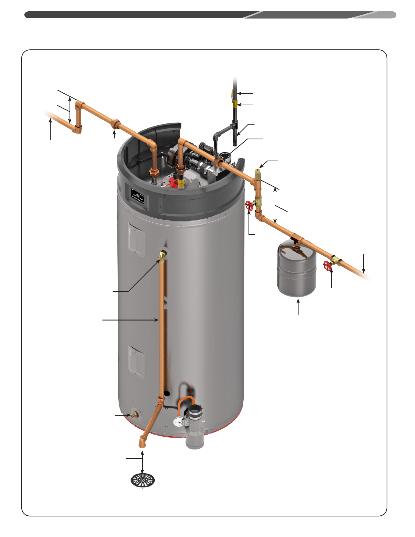
TYPICAL INSTALLATION
INSTALLATION
To Gas Supply
Manual Gas Shut Off
Drain Valve
Union
Union
Thermal Expansion Tank
(Not Supplied)
If required, install per
local codes and tank
manufacturer's instructions.
Too cold
water
supply
Vacuum Relief Valve (Not supplied)
If required, install per local codes and
valve manufacturer's instructions
Heat Trap
6" Minimum
Heat Trap
6" Minimum
Shut-off
Valve
Shut-off
Valve
Sediment Trap
Temperature & Pressure
Relief Valve
Discharge Line to
suitable open drain
Air Gap 6"
NOTES:
The gas supply piping
must be adequately
supported and aligned to
minimize loads (forces)
on the water heater's gas
valve and burner system.
Hot water
outlet to
fixtures
3/4" Check Valve
with 1/8" Hole
Pressure Gauge
Hot water line
Cold water line
3/4" Shut-Off
Valve (Typ.)
Gas Line
3/4" cold water
supply
Heat Trap
6” Min.
3/4" Shut-Off
Valve (Typ.)
2 Gallon Thermal Expansion
Tank (if required-not supplied
with water heater)
3/4" Shut-
Off Valve
(Typ.)
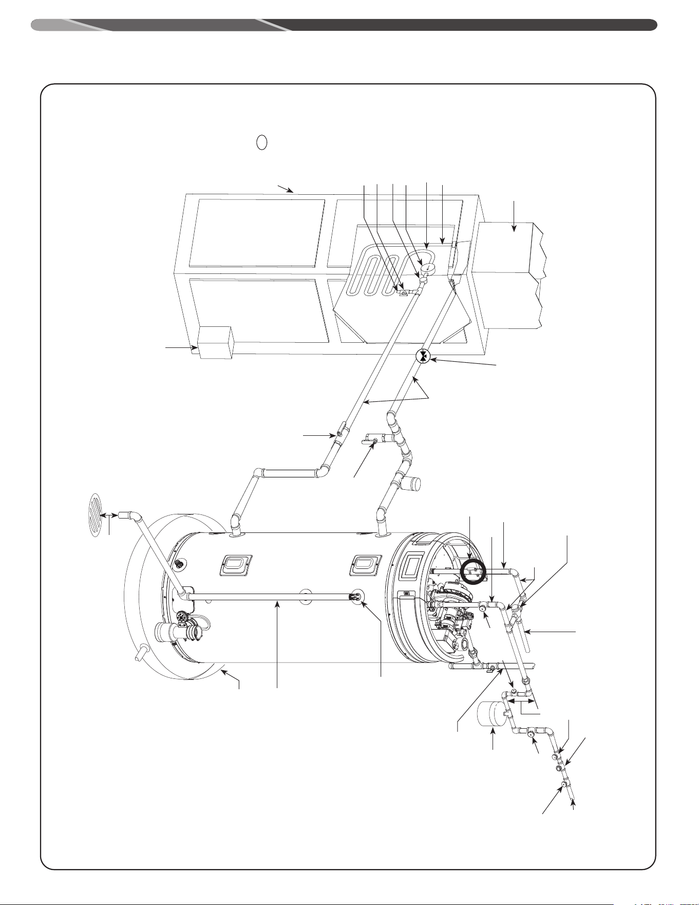
3/4" Tempered
domestic hot water
supply to house.
Minimum of 2'-0" developed length
of 3/4" type "L" copper from the
water heater connection.
Nominal 3/4" size mixing or
tempering valve (refer to warning
above). Follow mixing or tempering
valve manufacturer’s instructions
for installation of the valve.
Isolation valve in hot water
supply line to heating unit (not
supplied with water heater)
See diagrams above for proper
pipe application for vertical
or horizontal supply lines.
Temperature and Pressure Relief
Valve, tie to location approved by
local code
Temperature and pressure
relief valve discharge line
140°F (60°C)
120°F (49°C) to
130°F (54°C)
Water Heater drain pan installed
in accordance with the Local and
State Code
6” Air Gap
Isolation valve in
cold water return
line from heating
unit (not supplied
with water heater)
Drain valve
(not supplied
with water
heater)
Air vent
3/4" HWS & HWR
to Heating Coil.
Water Heater drain pan installed
in accordance with the Local
and State Code
Air Handler
T
FAN
ON
OFF
HEAT
COOL
To HVAC Unit.
Piping loop between
water heater and fan
coil shall be flow guard
gold CPVC or equal
Hot water to
space heater
Hot water coil
All bronze pump
Check valve internal
in pump
Air bleed valve
Water Sample Tap
Flow Control
Valve
12
TYPICAL PIPING DIAGRAM FOR COMBINATION POTABLE/SPACE HEATING INSTALLATION’
INSTALLATION
13
INSTALLATION
VENT AND COMBUSTION AIR INLET
NOTE: This unit can be vented either as a direct vent or power
vent configuration.
NOTE: Power vent installations are Category IV.
!
WARNING:
DO NOT connect this water heater to an existing vent
or chimney; it must be vented separately from all other
appliances, using only approved venting materials.
!
WARNING:
Failure to properly vent the water heater to the outdoors
as outlined above and in the following section can result in
unsafe operation of the water heater causing bodily injury,
explosion, fire or death.
!
DANGER:
To avoid the risk of fire, explosion, or asphyxiation from
carbon monoxide, NEVER operate the water heater unless
it is properly vented and the vent and combustion air inlet
systems are properly installed as detailed in the "Vent and
Combustion Air-Inlet" section of this manual.
The vent and combustion air inlet pipes must overlap a
minimum of 1/2 in. (1.3 cm) at each joint. It is important that
the vent and combustion air inlet pipes engage fully into any
pipe fitting and be kept in that position until the adhesive
has fully cured. DO NOT drill or punch holes in the plastic
pipe or fittings.
IMPORTANT
Where state and/or local codes require vent terminations,
as specified in this Use and Care Manual to be certified
to the UL 1738 Standard for Venting Systems for Gas-
Burning Appliances, Categories II, III, and IV, contact the
Manufacturer’s National Service Department (see last page).
NOTICE:
This unit can be vented using only the below
recommended pipe material. Use only 2, 3, or 4 inch
diameter pipe.
Refer to local codes for restrictions on the use of PVC, CPVC,
PP or ABS pipe and fittings. All exhaust venting materials for
products installed in Canada must meet ULC-S636.
NOTE: For the State of Massachusetts, use only plastic piping,
fittings and vent terminations as spedified in the manual
which are approved by the Massachusetts Board of State
Examiner of Plumbers and Gas for venting of appliances (see
link below):
https://licensing.reg.state.ma.us/pubLic/pl_products/pb_pre_
form.asp
PVC (DWV, ASTM-D2665 or CSA B181.2)
PVC (Schedule 40, ASTM-D1785 or CSA B137.3)
PVC (SDR Series, ASTM-D2241 or CSA B137.3)
CPVC (CPVC 4120, ASTM-D2846 or CSA B137.6)
CPVC (Schedule 40, ASTM-F441 or CSA B137.3)
CPVC (SDR Series, ASTM-F442)
ABS (Schedule 40, DWV, ASTM-D2661 or CSA B181.1)
ABS (Schedule 40, DWV, Cellular Core, ASTM-F628)
Polypropylene
14
NOTICE:
Use of PVC cellular core (ASTM-F891), ABS Schedule 40, DWV
cellular core (ASTM –F628), or Radel® (polyphenylsulfone) in
non-metallic venting systems is prohibited.
The unit may be vented horizontally through a wall or vertically
through the roof. Pipe runs must be adequately supported along
both vertical and horizontal runs. Maximum unsupported span
is recommended to be no more than 3 feet. It is imperative that
the first hanger be located on the horizontal run immediately
adjacent to the first 90-degree elbow from the vertical rise or at
the blower outlet. The support method used should isolate the vent
pipe from floor joists or other structural members to help prevent
the transmission of noise and vibration. DO NOT support, pin, or
otherwise secure the venting system in a way that restricts the
normal thermal expansion and contraction of the chosen venting
material.
If the water heater is being installed as a replacement for an
existing power vented or power direct vented water heater, a
thorough inspection of the existing venting system must be
performed prior to any installation work. Verify that the correct
materials, as detailed above, have been used and that the
minimum or maximum vent length and terminal locations, as
detailed in this manual, have been met. Carefully inspect the entire
venting system for any signs of cracks or fractures, particularly at
the joints between elbows or other fittings and the straight runs of
vent pipe. Check the system for signs of sagging or other stresses
in the joints as a result of misalignment of any components in
the system. If any of these conditions are found, they must be
corrected in accordance with the venting instructions in this
manual before completing the installation and putting the water
heater into service.
Additional installation information for The Common wealth of
Massachusetts is located on the back page of this manual.
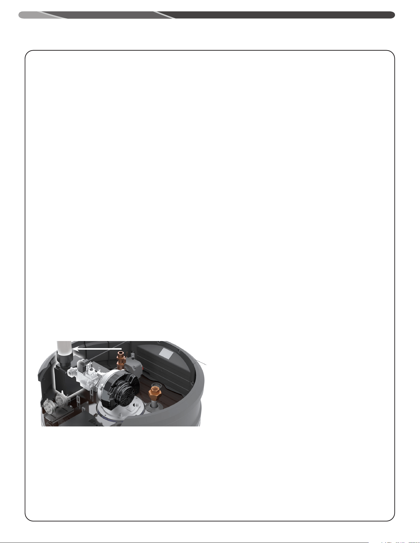
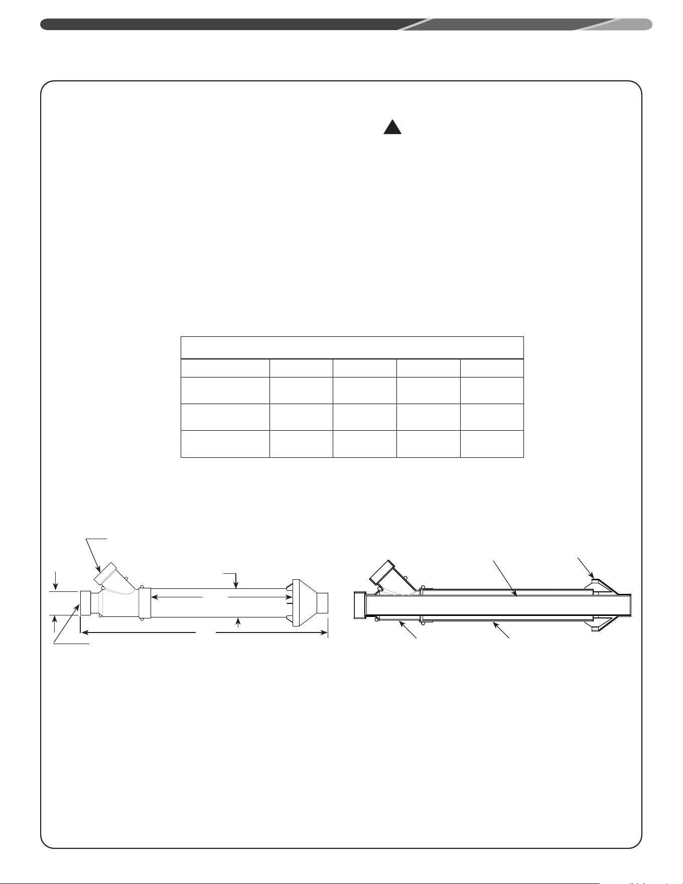
VENT PIPE CONNECTION
Refer to "Vent Pipe Connection Locations" Figure, for connecting
the vent pipe to the water heater. These models can be vented
either as a direct vent or as a power vent water heater.
NOTICE:
If the unit is installed as a power vent water heater, the vent
terminal with screen must still be installed on the inlet air side.
INSTALLATION
Before starting the vent installation, careful planning of the
routing and termination of vent and air inlet pipes can reduce
installation times. The length of the vent and air inlet pipes
should be kept to a minimum. Refer to the venting charts in
Table 1 for the pipe sizes and the total equivalent length of
pipe that can be used. DO NOT exceed the equivalent length of
pipe in the charts.
Depending on the size of pipe selected for venting the water
heater, it may be necessary to use a fitting for stepping up
to connect to the water heater. DO NOT step down pipe size
below the 2" pipe size. All models are shipped with 2" vent
terminals with screen. If another size of pipe is used for
venting the unit, the proper vent terminal must be installed.
When the unit is vented as a direct vent, through a side wall,
the vent terminals must be on the same exterior wall mounted
horizontally and maintain a minimum distance between the
centers of 15" (38.1 cm).
JOINING PIPES AND
FITTINGS
All pipe, fittings, solvent cement, primers, and procedures,
must conform to American National Standards Institute and
American Society for Testing and Materials (ANSI/ASTM)
standards in the U.S. For Canada, all pipe, fittings, solvent
cement, primers, and procedures must conform to ULC-S636
and vent manufacture specifications.
CEMENTING JOINTS
NOTICE:
All pipe, fittings, solvent cement, primers and procedures
must conform to American National Standards Institute and
American Society for Testing and Materials (ANSI/ASTM)
standards.
All joints in the vent piping must be properly sealed. Use of the
following material is recommended:
PVC materials should use ASTM D-2564 grade cement.
CPVC materials should use ASTM F-493 grade cement.
ABS materials should use ASTM D-2235 grade cement.
(ABS is not allowed in Canada)
Cleaner-Primer and Medium Body Solvent Cement
1. Cut the pipe end square, removing all jagged edges and
burrs. Chamfer the end of the pipe, and, then, clean the
fitting socket and pipe joint area to remove all dirt, grease,
and moisture.
2. After checking pipe and socket for proper fit, wipe the
socket and pipe with cleaner-primer. Apply a liberal coat of
primer to the inside surface of the socket and the outside of
the pipe. DO NOT allow the primer to dry before applying the
cement.
Blower Air Inlet
Connection
Noise
Reducer
VENT PIPE CONNECTION LOCATIONS
15
INSTALLATION
3. Apply a thin coat of cement evenly in the socket. Quickly
apply a heavy coat to the pipe end. Insert the pipe into the
fitting with a slight twisting motion until it bottoms out.
NOTICE:
Cement must be fluid; if not, re-coat.
4. Hold the pipe fitting for 30 seconds to prevent the tapered
socket from pushing the pipe out of the fitting.
5. Wipe all excess cement from the joint with a rag. Allow
15 minutes for drying before handling. Cure time will vary
according to fit, temperature, and humidity.
NOTICE:
Stir the solvent cement frequently while using. Use a
natural bristle brush or the dauber supplied with the can.
The proper brush size is one inch.
FOR PROPER
INSTALLATION
CAUTIONS:
• DO NOT use solvent cement that has become curdled,
lumpy or thickened.
• DO NOT thin solvent cement. Observe shelf precautions
printed on the containers.
• For applications below 32°F (0°C), use only low
temperature type solvent cement.
• Appropriate solvent and cleaner must be used for the
type of vent pipe used (PVC, CPVC, PP, or ABS).
DANGER OF FIRE OR
BODILY INJURY
Solvent cements and primers are highly flammable. Provide
adequate ventilation and do not assemble near a heat source
or open flame. DO NOT smoke. Avoid skin or eye contact.
Observe all cautions and warnings on material containers.
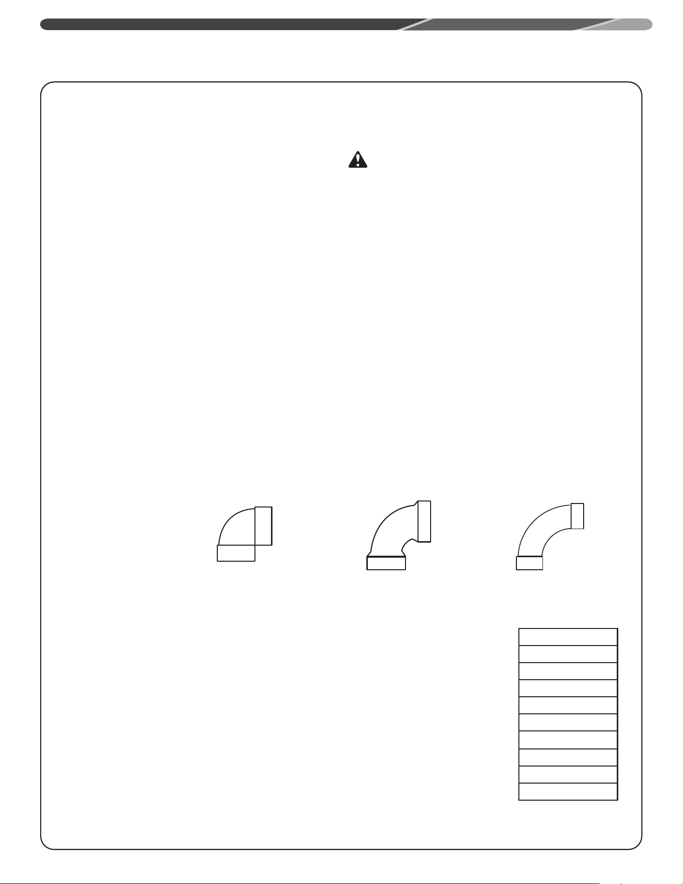
Additional Fitting Considerations
10 Feet Equivalent
length
8 Feet Equivalent
Length
5 Feet Equivalent
Length
Short Sweep 90°
Elbow
Standard 90°
Elbow
Long Sweep 90°
Elbow
EXAMPLES OF ELBOWS:
It is recommended to
use only standard and/or
long sweep elbows. See
examples as shown.
Minimum and Maximum Vent Lengths
Important information for all installations:
1) The minimum required venting is what is required to safely extend the inlet and outlet vent pipes
outside of the building.
2) Each 90° elbow (standard or long sweep elbow) reduces the
equivalent vent length as shown.
3) Each 45° elbow reduces the equivalent vent length by 2 1/2 feet (0.8m).
4) DO NOT mix pipe sizes for venting these models, use only one size of pipe for all venting.
5) All vent terminations (horizontal or vertical) should be a minimum of 24 inches (61cm) and a maximum
of 36 inches (91 cm) apart, as measured from center to center of terminals.
Exceeding the maximum equivalent vent lengths may cause the water heater to malfunction or cause a
lock-out condition.
Feet to Meters
20 6.1
50 15.2
60 18.3
70 21.3
80 24.4
100 30.5
120 36.6
130 39.6
170 51.8
16
INSTALLATION
NOTE: The intake and exhaust connections are set-up with 2" Schedule 40 pipe size. An adapter may be used to increase pipe size to 3"
and 4" along the length of the vent and air intake. Vent and air intake pipes should always be set-up to the same size. The vent length
calculations should be based upon termination size.
Follow manufacturers instructions for installation of flex
vents.
All power direct models can use 2 in. concentric venting only as listed in
the above chart.
2 inch concentric vent can only be used with 2 inch rigid piping.
DO NOT mismatch concentric vent terminations with different rigid
piping as it may cause the heater to malfunction or cause a lock-out
condition unless specifically mentioned.
3" Concentric vent may be used with 3" and 4" venting.
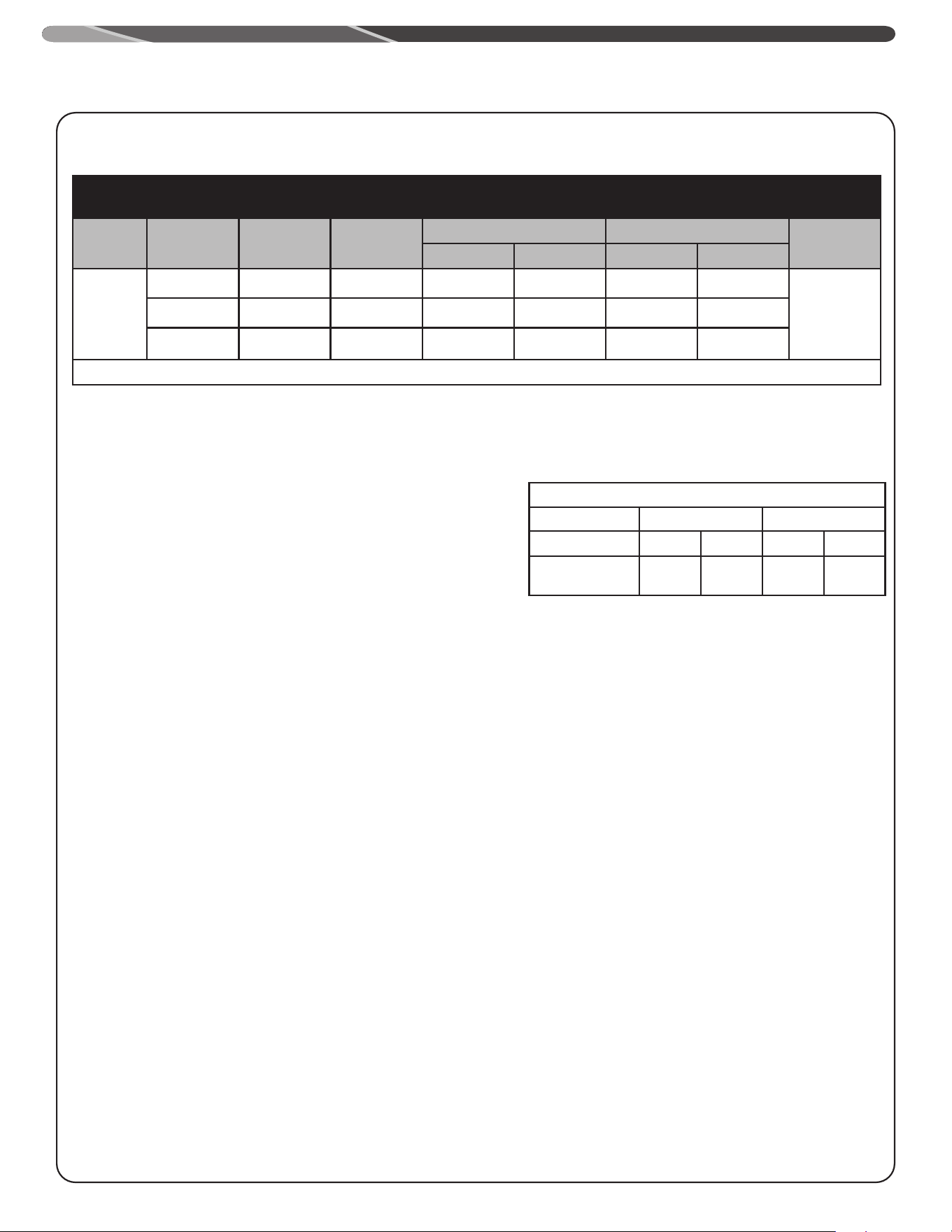
Flexible Polypropylene pipe (ft)
Pipe Size (IN.)
2" 3"
Intake Exhaust Intake Exhaust
Max PV
0
30'
(13m)
0
30'
(13m)
Commercial Equivalent Vent Lengths
50G-76K, 50G-100K, 75G; POWER VENT
CONFIGURATION; (RIGID PIPE)
50G-76K, 50G-100K, 75G; POWER DIRECT VENT
CONFIGURATION; (RIGID PIPE)
Elevation
(Feet)
Vent Size
(Inches)
Nat Max Eq.
Length (Feet)
LP Max Eq.
Length (Feet)
Nat Max Eq. Length(Feet) LP Max Eq. Length (Feet)
Terminations
Intake Exhaust Intake Exhaust
0-10,100
2" 40' 40' 40' 40' 40' 40'
2" AND 3"
90° ELBOWS,
2", 3" AND 4"
CONCENTRIC
AND 2"AND 3"
PANCAKE
3" 140' 140' 140' 140' 140' 140'
4" 140' 140' 140' 140' 140' 140'
MINIMUM INTAKE AIR AND EXHAUST VENT: 10' EQUIVALENT LENGTH
17
INSTALLATION
Direct Vent Installation
Check to make sure flue gases DO NOT recirculate into the air
intake terminal when using direct venting. If the water heater is
having service issues, flue recirculation may be a contributing
factor.
Even when the minimum vent terminal separation distances
are followed, recirculation may still occur, depending upon the
location outside the building, the distance from other buildings,
proximity to corners, weather conditions, wind patterns, and
snow depth.
Periodically check to make sure that flue recirculation is not
occurring. Signs of flue gas recirculation include frosted or
frozen intake terminals, condensate in the intake terminal and
venting system, oxidation, or white chalk material on the flame
sensor or igniter shield. Correction to flue recirculation may
involve angling the intake away from the exhaust terminal,
increasing the distance between them, or using inside air for
combustion. Check to be sure the intake and exhaust terminals
are not obstructed, especially during periods of below freezing
weather.
All intake and exhaust venting components must have the
same diameter size. DO NOT use a different size on the intake
and exhaust venting.
Be sure the condensate runs freely to a drain and does
not accumulate inside the water heater. In cold climates,
precautions may need to be taken to insure that the condensate
drain does not freeze. Make sure the condensate trap or drain
loop is installed to prevent flue gases from being discharged
into the room. Refer to the "Venting" section of this manual for
complete instructions on venting and condensate drainage.
Stress levels in the pipe and fittings can be significantly
increased by improper installation. If rigid pipe clamps are
used to hold the pipe in place, or if the pipe cannot move freely
through a wall penetration, the pipe may be directly stressed,
or high thermal stresses may be formed when the pipe heats
up and expands. Install accordingly to minimize such stresses.
Follow the below procedure to vent through the wall.
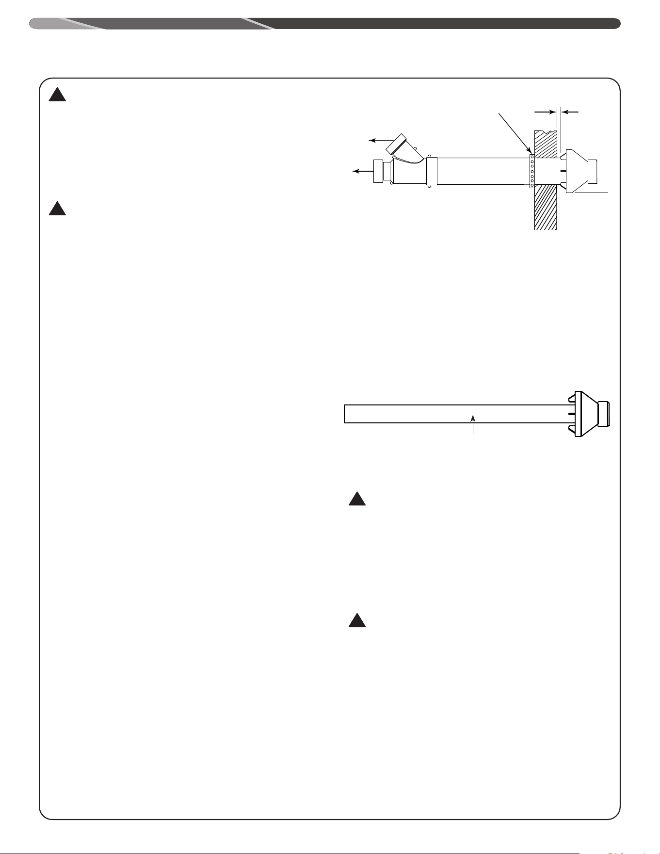
1. Cut two holes for the pipe to pass through. The hole diameter
should be 2.5" (6.4 cm) for 2" pipe, 3.5" (8.9 cm) for 3" pipe.
Vent terminals must maintain a horizontal distance apart in
the range of 24" min. (61 cm).
2. Use the proper PVC cement (primer and adhesive) to secure
the exhaust vent and air intake terminals provided with the
water heater to the plastic pipes. The distance between
the back edge of the exhaust vent terminal and the exterior
wall must be 6 inches (12.7 cm) more for the exhaust vent
terminal than the air intake terminal. Use the proper cement
or sealant and assembly procedures to secure the vent
connector joints between the terminal and the blower outlet.
Provide support brackets every 3 feet (.91 m) of horizontal
vent beyond the intake terminal.
18
Min. 24"
Inlet Outlet
Additional considerations in the following pages.
DO NOT install vent terminals under any patio or deck.
To help prevent moisture from freezing on walls and under eaves,
DO NOT locate outlet vent terminal on the side of your home with
prevailing winter winds.
DO NOT terminate vent pipe directly on brick or masonry
surfaces. Use a rust-resistant sheet metal backing plate behind
vent. (See Figure above.)
DO NOT locate vent terminal too close to shrubbery, since flue
gases may damage them.
Caulk all cracks, seams and joints within 6 feet
(1.83 m) of vent terminal.
All painted surfaces should be primed to lessen the chance of
physical damage. Painted surfaces will require maintenance.
Make sure that all vent pipes exposed to cold conditions (attics,
crawl spaces, etc.) have the proper slope and support to keep
moisture from accumulating in the vent pipes. NOTE: Insulating
of non-metallic vent materials is prohibited.
This water heater requires its own separate venting system.
DO NOT connect the exhaust vent to an existing vent pipe or
chimney.
Moisture in the flue gas will condense as it leaves the vent
terminal. In cold weather this condensate can freeze on the
exterior wall, under the eaves, and on surrounding objects. Some
discoloration to the exterior of the building is to be expected;
however, improper location or installation can result in severe
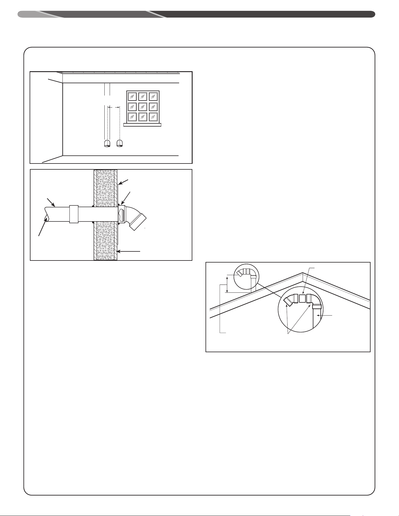
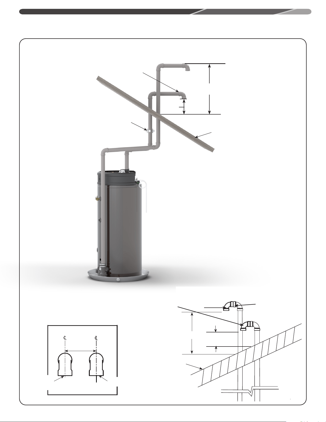
TYPICAL HORIZONTAL VENT INSTALLATION
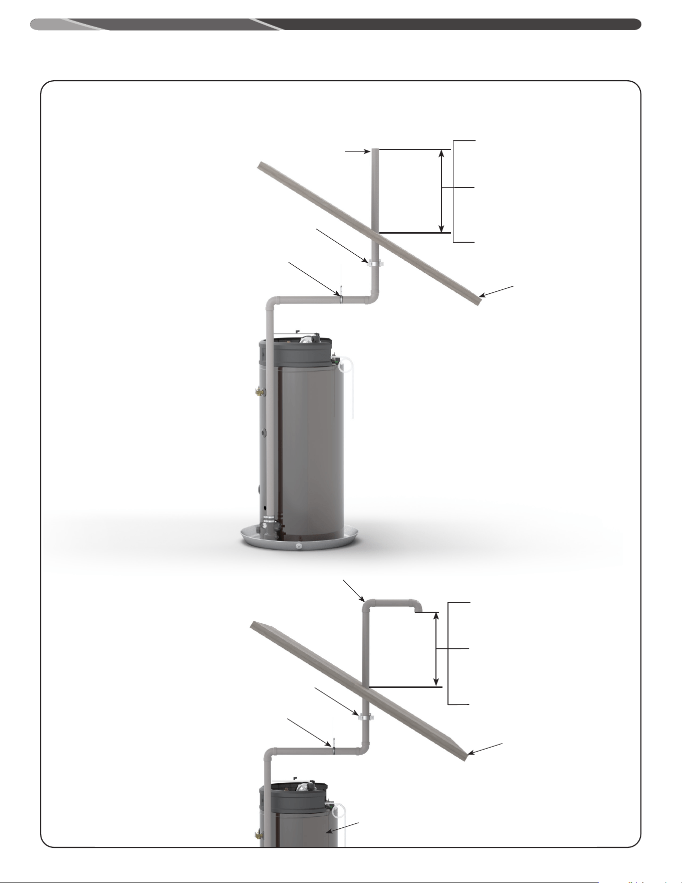
VERTICAL VENT TERMINAL LOCATION
Short Piece of Vent
Pipe
*Min. 12"(30.5 cm)
Above Roof or
Min. 12"(30.5 cm) Above
Anticipated Snow Level.
Max. 24"(61 cm) Above
Roof (Without Additional
Support)
Vent Pipe
Through
Roof
Elbows
* Min of 18"(46 cm) for Canada
Pipe &
Coupling
Sheet Metal Shield on
Brick or Masonry Walls
Outside of the
Building Wall
To the Water Heater
Vent Pipe
Inlet Vent Terminal
with 1/2" Mesh
Protective
Screen Inside
Vent
Pipe
Elbow can be a maximum
of 1 inch from the wall.
damage to the structure or exterior finish of the building. In
locations with extended amounts of time with temperatures
under 40°F. (4°C.) and/or prevailing wind toward the outlet
vent, make sure that the outlet vent terminal is at least 2 feet
(0.61 m) away from anything that can be damaged by the
condensate.
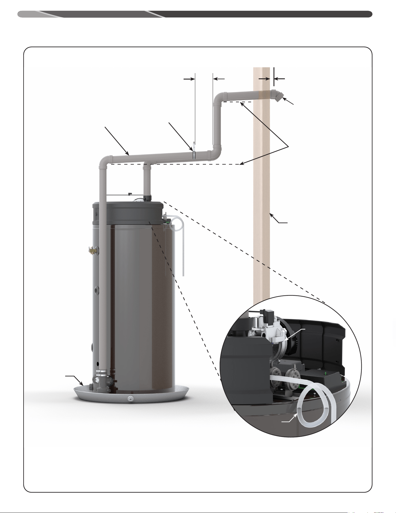
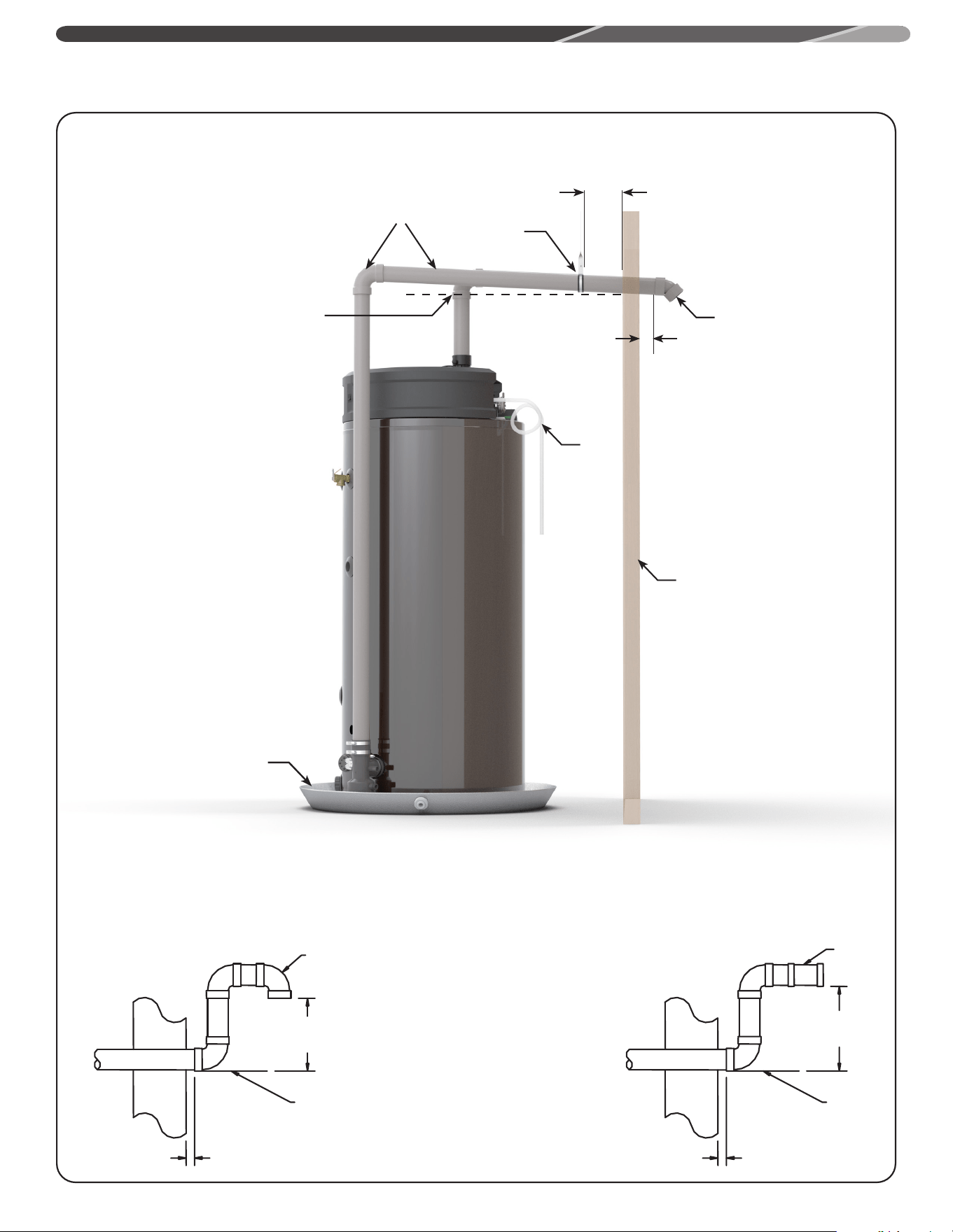
HORIZONTAL VENT
INSTALLATION
Once the vent terminal location has been determined, make a
hole through the exterior wall to accommodate the vent pipe.
The vent pipe must exit the exterior wall horizontally only (See
Typical Horizontal Vent Installation Figure on this page).
Insert a small length of vent pipe through the wall, and connect
the coupling as shown in Typical Horizontal Vent Installation
Figure. Connect the vent terminal as shown to the vent pipe on
the exterior of the building. Seal any opening around the vent
pipe or fittings with mortar or silicone caulk as shown in Typical
Horizontal Vent Installation Figure.
Complete the rest of the vent pipe installation to the water
heater’s vent connector fitting on the blower outlet. If necessary,
support the horizontal run of pipe as previously mentioned.
VERTICAL VENT
INSTALLATION
Once the vent terminal location has been determined, make
a hole through the roof and interior ceiling to accommodate
the vent pipe. Complete the vent pipe installation to the water
heater’s vent connector fitting on the blower outlet. Support
vertical or horizontal runs as previously mentioned.
Install adequate flashing where the vent pipe passes through
the roof. Determine the vent terminal height and cut the vent
pipe accordingly. Refer to Vertical Vent Terminal Location Figure
for the proper vent terminal height. Connect the vent elbow onto
the vertical pipe through the roof. Connect a short piece of vent
pipe (approximately 3" (7.6 cm) long) to the elbow, and, then,
join the vent terminal to the short piece of vent pipe.
INSTALLATION
19
D
V
V
E
FIXED
CLOSED
O
P
ERA
BL
E
O
PE
R
A
BL
E
FIXE
D
CLOSED
v
v
B
L
F
C
B
v
v
v
X
B
B
B
A
J
C
I
H
X
v
M
K
v
G
A
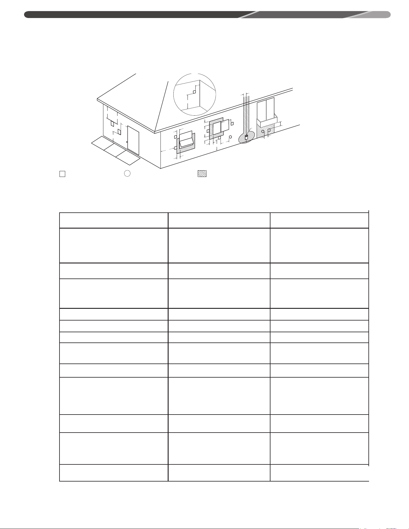
The following information should be used for determining the proper location of the vent terminal
for direct vent water heaters.
V
VENT TERMINAL
X
AIR SUPPLY INLET
AREA WHERE TERMINAL IS NOT PERMITTED
HORIZONTAL VENT TERMINAL LOCATION FOR POWER DIRECT VENT
Canadian Installations
1
US Installations
2
A= Clearance above grade, veranda, porch, deck or
balcony.
12 inches (30 cm) 12 inches (30 cm)
B= Clearance to window or door that may be opened.
• 6 in (15 cm) for appliances < 10,000 Btuh (3
kW),
• 9 in (23 cm) for appliances > 10,000 Btuh (3
kW) and < 50,000 Btuh (15 kW),
• 12 in (30 cm) for appliances > 50,000 Btuh (15
kW)
• 6 in (15 cm) for appliances < 10,000 Btuh (3
kW),
• 9 in (23 cm) for appliances > 10,000 Btuh (3
kW) and < 100,000 Btuh (30 kW),
• 36 in (91 cm) for appliances > 100,000 Btuh
(30 kW)
C= Clearance to permanently closed window.
0 in (0 cm) 0 in (0 cm)
D= Vertical Clearance to ventilated soffit located
above the terminal within a horizontal distance of
2 feet (61 cm) from the center line of the terminal.
12 in (30 cm) 12 in (30 cm)
E= Clearance to unventilated soffit.
12 in (30 cm) 12 in (30 cm)
F= Clearance to outside corner.
24 in (61 cm) 24 in (61 cm)
G= Clearance to inside corner.
18 in (46 cm) 18 in (46 cm)
H = Clearance to each side of center line extended
meter/regulator assembly. above
3 ft (91 cm) within a height of 15 ft (4.6 m) 3 ft (91 cm) within a height of 15 ft (4.6 m)
I = Clearance to service regulator vent outlet.
3 ft (91 cm) 3 ft (91 cm)
J = Clearance to nonmechanical air supply inlet to the
building or the combustion air inlet of any other
appliance..
• 6 in (15 cm) for appliances < 10,000 Btuh (3 kW),
• 9 in (23 cm) for appliances > 10,000 Btuh (3 kW)
and < 100,000 Btuh (30 kW),
• 36 in (91 cm) for appliances > 100,000 Btuh (30
kW)
• 6 in (15 cm) for appliances < 10,000 Btuh (3
kW),
• 9 in (23 cm) for appliances > 10,000 Btuh (3
kW) and < 50,000 Btuh (15 kW),
• 12 in (30 cm) for appliances > 50,000 Btuh
(15 kW)
K = Clearance to mechanical air supply inlet.
6 ft (1.83 m)
3 ft (91 cm) above if within 10 ft (3 m)
horizontally
L = Clearance above paved side walk or paved
driveway located on public property.
7 ft (2.13 m)
7 ft (2.13 m) for mechanical draft system
(Category I appliances); vents for Category II
and IV appliances cannot be located above public
walkways or other areas where condensate or
vapor can cause a nuisance or hazard
M = Clearance under veranda, porch, deck or balcony.
12 in (30 cm) ‡
12 in (30 cm)*
Direct Vent Terminal Clearances
1
In accordance with the current CSA B149.1, Natural Gas and Propane Installation Code
2
In accordance with the current ANSI Z223.1/ NFPA 54 National Fuel Gas Code.
‡ Permitted only if veranda, porch, deck, or balcony is fully open on a minimum of two sides beneath the oor.
* Permitted only if veranda porch, deck, or balcony is fully open on a minimum of two sides beneath the oor.
Follow local or National gas codes or latest edition of CAN/CSA B149 and Propane installation code.
INSTALLATION

20
VENT INSTALLATION – Before proceeding, make certain
you understand the procedure and cautions covered in the
section “Joining Pipes and Fittings.”
POWER VENT INSTALLATION – Power venting is where the
indoor air is used and the exhaust is vented to the outside.
Venting may be run horizontally through an outside wall or
vertically through a roof through using either 2" (5.1 cm),
3" (7.6 cm), 4" (10.2 cm) diameter PVC, ABS, CPVC or PP.
This water heater is supplied with a screened intake elbow
and exhaust coupling referred to as the air intake terminal
and the exhaust vent terminal.
NOTE: Flexible PP vent kit is available for Power Vent
configurations, in 2" and 3" diameters. These kits should
be used for vertical venting only.
NOTICE:
Use of PVC cellular core (ASTM-F891), ABS Schedule
40 DWV cellular core (ASTM –F628), or Radel®
(polyphenylsulfone) in non-metallic venting systems is
prohibited.
In a horizontal application, it is important that condensate
not be allowed to buildup in the exhaust vent pipe. To
prevent this from happening, the pipe should be installed
with a slight upward slope of ¼” per foot. The vent system
must be supported every 5 feet of vertical run and every 3
feet of horizontal run of vent pipe length.
Failure to properly support the vent piping with hangers
and clamps may result in damage to the water heater or
venting system.
Follow local or National gas codes or latest edition of ANSI standard Z223.1 or CAN/CSA B149 and Propane installation code
• DO NOT terminate near soffit vents or crawl space or other area where condensate or vapor could create a nuisance hazard
or cause property damage.
• DO NOT locate the exhaust vent terminal where condensate or vapor could cause damage or could be detrimental to the
operation of regulators, relief valves, or other equipment.
• DO NOT locate the exhaust vent terminal over public area or walkways where condensate or vapor can cause nui sance or
hazard.
• DO NOT locate the vent termination in proximity to plants/shrubs.
INSTALLATION
21
D
V
V
E
FIXED
CLOSED
O
P
ERA
BL
E
O
PE
R
A
BL
E
FIXE
D
CLOSED
v
v
B
L
F
C
B
v
v
v
X
B
B
B
A
J
C
I
H
X
v
M
K
v
G
A
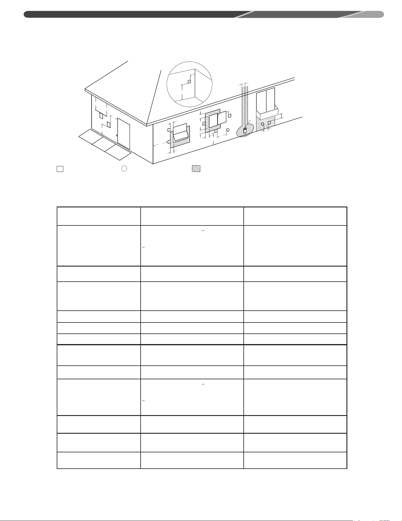
The following information should be used for determining the proper location of the vent terminal for
direct vent water heaters.
V
VENT TERMINAL
X
AIR SUPPLY INLET
AREA WHERE TERMINAL IS NOT PERMITTED
HORIZONTAL VENT TERMINAL LOCATION FOR POWER VENT
Canadian Installations
1
US Installations
2
A= Clearance above grade, veranda,
porch, deck or balcony.
12 inches (30 cm) 12 inches (30 cm)
B= Clearance to window or door that may
be opened.
6 inches (15 cm) for appliances < 10,000 Btuh (3
kW), 12 inches (30 cm) for
appliances > 10,000 Btuh (3kW) and
< 100,000 Btuh (30kW), 36 inches (91 cm) for
appliances > 100,000 Btuh (30kW).
4 feet (1.2 m) below or to side of opening; 1 foot
(300 mm) above opening.
C= Clearance to permanently closed
window.
0 in (0 cm) 0 in (0 cm)
D= Vertical Clearance to ventilated soffit
located above the terminal within a
horizontal distance of 2 feet (61 cm)
from the center line of the terminal.
12 in (30 cm) 12 in (30 cm)
E= Clearance to unventilated soffit. 12 in (30 cm) 12 in (30 cm)
F= Clearance to outside corner. 24 in (61 cm) 24 in (61 cm)
G= Clearance to inside corner. 18 in (46 cm) 18 in (46 cm)
1 In accordance with current CAN/CSA-B149.1 Installation Codes.
2 In accordance with current ANSI Z223.1/ NFPA 54 National Fuel Gas Code.
+ A vent shall not terminate directly above a sidewalk or paved driveway that is located between two single family dwellings and
serves both dwellings.
* "Clearance in accordance with local installation codes and the requirements of the gas supplier."
H = Clearance to each side of center line
extended meter/regulator assembly.
above
3 feet (91 cm) within a height 15 feet (4.57 m) above
the meter/regulator assembly.
3 ft (91 cm) within a height of 15 ft (4.6 m)
I = Clearance to service regulator vent
outlet.
3 feet (91 cm)
3 ft (91 cm)
J = Clearance to nonmechanical air supply
inlet to building or the combustion air
inlet to any other appliance..
6 inches (15 cm) for appliances < 10,000 Btuh (3
kW), 12 inches (30 cm) for
appliances > 10,000 Btuh (3kW) and
< 100,000 Btuh (30kW), 36 inches (91 cm) for
appliances > 100,000 Btuh (30kW).
4 feet (1.2 m) below or to side of opening; 1 foot
(300 m) above opening.
K = Clearance to mechanical air supply
inlet.
6 feet (1.83 m)
3 feet (91 cm) above if within 10 feet (3 m)
horizontally.
L = Clearance above paved side walk or
paved driveway located on public
property.
7 feet (2.13 m)+ 7 feet (2.13 m)+
M = Clearance under veranda, porch, deck
or balcony.
Not Allowed Not Allowed
Power Vent Terminal Clearances
INSTALLATION
22
2, 3 or 4 inch pipe
and fittings
Support
Bracket
Every 3' Max.
45° Terminal
Raise horizontal pipe
upward 1/4 in. per foot
(10 mm per m) min.
Wall
Water
Heater
Drain Pan
1 In. Max.
Drain
Tube
Blower Air Inlet
Connection
• Connect 1/2 in. I.D., flexible, PVC (or equivalent material), clear tubing to the drain port.
NOTICE: The tubing must be of sufficient length to reach a floor drain, outside the building
or other required condensate disposal termination requirements (Refer to local codes).
• Loop the drain tube so that it has a circular trap and secure the top and bottom of the loop
with wire ties or plastic zip ties as shown. DO NOT restrict any portion of the drain tube. The
loop and all sections of the tube must not be restricted or collapsed.
• Fill drain tube to prevent combustion gases from venting into the home.
• Route the drain tube to a floor drain or outside the building or refer to local codes for any
condensation requirements.
Typical Horizontal Direct Vent System
INSTALLATION
23
Water
Heater
24" (61 cm) Min
(Support required).
90° Intake Terminal
Support Bracket
"D"
Typical Vertical Direct Vent System Installation
24 in.
(61 cm)
Min.
Combustion Air-Inlet
Terminal
Exhaust
Vent
Terminal
-B-
-A-
-B-
d
.008
d
.010
"D"
Min. 12 in. (30 cm) for US and
Min. 18 in. (46 cm) for Canada
above Roof
Min. 12 in. (30.5 cm) above
anticipated snow level
Max. 24 in. (61 cm) above roof
without
additional support)
Terminals with 1/2 in.
(1.3 cm) Mesh
Protective Screen.
Exercise discretion
in using protec-
tive screens in cold
climates to prevent
formation of ice
Elbow
Short Piece of Pipe
"D"
Combustion Air-Inlet
"D"
Terminals spacing for horizontal
or vertical venting.
Exhaust Vent
INSTALLATION
Roof
Roof
24
Direct Vent Vertical Vent Horizontal Intake
INSTALLATION
Roof
Wall
Roof
Wall
Direct Vent Horizontal Vent Vertical Intake
25
2, 3, or 4*
Inch Pipe
And Fittings
Slope horizontal pipe
downward 1/8 in. per
foot (10 mm per m) min.
45° Terminal
Wall
Drain
Tube
1 In. Max.
Support
Bracket
Every 3' Max.
Drain Pan
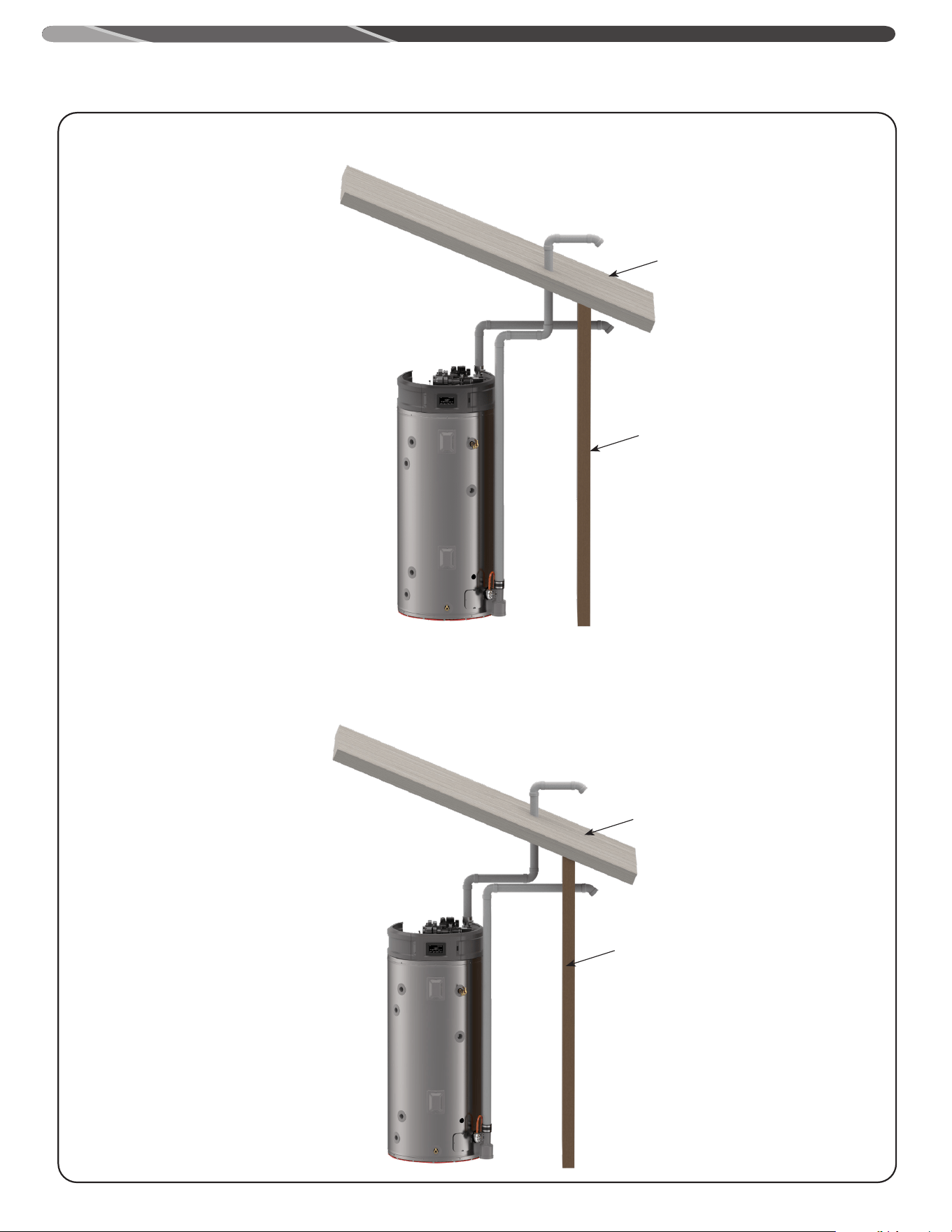
INSTALLATION
THROUGH THE WALL VENTING WITH LOW GROUND CLEARANCE:
When venting cannot exit through the wall at a height greater than or equal to 12” (30.5 cm) (and above expected snow level)
from the ground, then the installation must be modified as shown below.
90° Intake
Terminal
Exhaust
Terminal
"D"
"D"
Ground level
Ground
Level
1" (2.54 cm)
1" (2.54 cm)
"D"
Min. of 12" (31 cm)
above grade.
Min. of 12" (31 cm)
above anticipated snow
level.
Max of 24" (61 cm) with-
out additional support
Typical Horizontal Power Vent System
IMPORTANT:
In cold weather climates
vent must slope back
towards water heaters.
26
Straight Exhaust Terminal
Support Bracket
Water
Heater
Recommended support bracket be
placed on horizontal run
Min. 12" (30.5 cm) for US
and Min 18" (46 cm) for
Canada above roof.
Min. of 12" (30.5 cm)
above anticipated snow
level.
Max. 24" (61 cm) above
roof without additional
support.
Typical Vertical Power Vent System Installation
INSTALLATION
Water Heater
Support Bracket
Exhaust Terminal
Alternate vertical venting with
exhaust vent turned down -
preferred for cold climates.
Recommended support bracket be
placed on horizontal run
Min. 12" (30.5 cm) for US
and Min 18" (46 cm) for
Canada above roof.
Min. of 12" (30.5 cm)
above anticipated snow
level.
Max. 24" (61 cm) above
roof without additional
support.
Roof
Roof
27
PROCEDURE
Improper installation, adjustment, service, or
maintenance can cause property damage, personal
injury, or death. Consult a qualified installer, service
agency, or gas supplier for information or assistance.
This kit must be used only for terminating this water
heater. DO NOT use this termination kit for any other
appliance. Using this kit on other appliances and/or
water heaters can result in property damage, personal
injury, or death.
NOTICE:
Concentric vent kit requires that the joints be cemented.
!
CAUTION:
DO NOT operate this water heater with the rain cap
removed or recirculation of combustion products may
occur. Water may also collect inside larger
combustion-air pipe and flow to the burner assembly.
Failure to follow this warning could result in product
damage, improper operation, personal injury or death.
DO NOT use field-supplied couplings to extend pipes.
Airflow restriction will occur and the water heater
pressure switches may cause intermittent problems.
Installation:
1. Become familiar with concentric vent kit parts (see chart above).
2. Determine the best location for the termination kit.
3. Cut the recommended diameter hole for the nominal pipe size called out in the charts above – Dim. “D”.
4. Partially assemble the vent kit by performing the following:
a. Cement concentric Y fitting to larger diameter pipe (see chart above).
b. Cement rain cap to smaller diameter pipe (see chart above).
PVC Intake/Combustion Air
"C"
"D"
"A"
PVC Vent/Exhaust
"C"
Concentric "Y"
Fitting
"D" Diameter Pipe
"E" Diameter Pipe
Rain Cap
"B"
Concentric Vent Terminal Installation
INSTALLATION
Nominal PVC Dimensions
“A” “B” “C” “D”
2" Vent Kit 33.5" 17.65" 2.68" 3.5"
3” Vent Kit 39.5” 22.38” 3.83” 4.5” *
4” Vent Kit 53.75" 34.8" 4" 6"
*Hole size for nominal 4” PVC would be 5" (12.7 cm)
28
WARNING
These instructions are intended as an aid to qualified service
personnel for proper installation, adjustment, and operation of
this kit. Read these instructions thoroughly before attempting
installation, adjustment, or operation. Failure to follow these
instructions can result in improper installation, adjustment,
service, or maintenance possibly resulting in fire, electrical
shock, property damage, personal injury, or death.
WARNING:
This kit is to be used only for vent & combustion air-inlet
termination for power direct vent gas water heaters. DO NOT
use this kit to terminate any other type of appliance. Failure
to follow this warning could result in fire, personal injury, or
death.
LOCATION:
The Concentric Vent & Combustion Air-Inlet Termination Kit can
be installed in a horizontal or vertical (roof) orientation. Before
installation procedures begin, determine the best location for the
termination kit.
IMPORTANT:
When installing the kit, consider the following when choosing
a location:
• Kit is positioned where vent gases will not damage nearby
structure.
• Kit is positioned so that wind will not cause combustion
products, leaves, snow, or other debris to enter the
combustion air-inlet.
• Kit is positioned where it will not get damaged by foreign
objects.
• Kit is positioned where vent gases will not be inhaled or
cause a nuisance.
NOTE: Ensure that the heights of the vent and/or combustion air-
inlet openings are at least 12" above the anticipated snow level.
HORIZONTAL
INSTALLATION
STEP 1:
Cut the proper size opening (see "D" in chart) in the sidewall and
install the field supplied weather-seal boot/flashing for PVC pipe.
STEP 2:
From inside, insert the combustion air-inlet pipe through the
seal boot so that a maximum of 1” clearance occurs between
the outside wall and the rain cap fins (see the following Figure).
Ensure that no insulation or debris accumulate in the pipe.
STEP 3:
Secure the combustion air-inlet pipe using a field supplied
perforated strap of a suitable type material (see Figure above).
STEP 4:
Assemble the vent pipe assembly by cleaning and cementing the
rain cap to the smaller diameter vent pipe.
Note: If field disassembly is desired for cleaning, a stainless steel
screw may be used to secure the rain cap to the PVC vent pipe.
WARNING:
When using the alternate screw method, pre-drill a clearance
hole in the rain cap slightly larger than the screw and a pilot
hole in the vent pipe to prevent cracking of the PVC pipe.
Cracking of the PVC components will cause a failure of the
system, allowing combustion products to be recirculated.
Failure to follow this warning could result in personal injury of
death.
WARNING:
DO NOT operate the water heater with the rain cap and elbow
removed or recirculation of combustion products may occur.
The vent and combustion air-inlet systems may also take in
water, causing damage to the water heater. Failure to follow
this warning could result in damage to the unit, improper
operation, personal injury, or death.
STEP 5:
From the outside, slide the vent pipe assembly through the
combustion air-inlet pipe and cement the rain cap to the
combustion air-inlet pipe. From the inside, cement the "Y" fitting
to the combustion air-inlet pipe (refer to Figures in this page).
STEP 6:
Vent Pipe Assembly
1" Maximum
Combustion
Air-Inlet to
Water Heater
Field Supplied
Strap
Exhaust
Vent from
Water
Heater
Min. of 12"
(30.5 cm)
above grade
or antici-
pated snow
level.
!
!
!
!
HORIZONTAL AIR INLET PIPE INSTALLATION
INSTALLATION
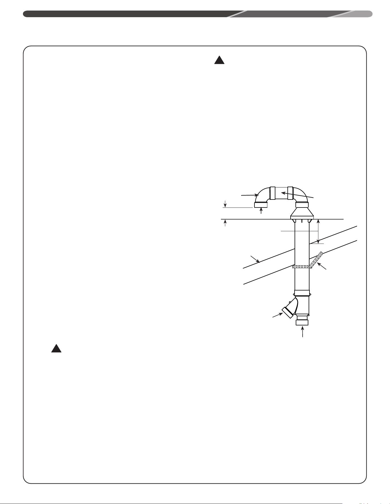
29
!
!
Complete the installation of the remainder of the vent and
combustion air-inlet systems as required in this manual.
VERTICAL
INSTALLATION
STEP 1:
Cut a proper size opening (see "D" in chart) in the roof,
and install field-supplied weather-seal boot/flashing for the
larger PVC pipe.
STEP 2:
From inside, insert the larger diameter combustion air-inlet
pipe up through the seal boot, ensuring that no insulation or
debris accumulate in the pipe. Ensure termination height is
above the 12” minimum clearance to combustion air inlet.
STEP 3:
Secure the combustion air-inlet pipe using a field supplied
perforated strap or a suitable type material. (see the Vertical
Air Inlet Pipe Installation Figure in this page).
STEP 4:
Assemble the vent pipe assembly by cleaning and
cementing the rain cap to the smaller diameter exhaust
pipe. Assemble the 90° elbow by cleaning and cementing it
to the rain cap. Assemble the field supplied PVC connector
and 90° elbow by cleaning and cementing them together
as shown in Vertical Air Inlet Pipe Installation Figure on this
page. The alternate screw method is not necessary for the
field supplied PVC parts.
NOTE: If field disassembly is desired for cleaning, a
stainless steel screw may be used to secure the rain cap to
the smaller diameter exhaust pipe.
WARNING:
When using the alternate screw method, pre-drill a
clearance hole in the rain cap slightly larger than
the screw and a pilot hole in the vent pipe to prevent
cracking of the PVC pipe. In a separate location, pre-drill
a slightly larger clearance hole in the 90° elbow and a
pilot hole in the rain cap for the screw being used at that
site. Cracking of the PVC components will cause a failure
of the system, allowing combustion products to be
recirculated. Failure to follow this warning could result in
personal injury of death.
WARNING:
DO NOT operate the water heater with the rain cap
removed or recirculation of combustion products may
occur. The vent air pipes may also take in water, causing
damage to the water heater. Failure to follow this
warning could result in damage to the unit, improper
operation, personal injury, or death.
STEP 5:
From the roof top, slide the vent pipe assembly down
through the intake pipe and cement the rain cap to the
intake pipe. From the inside, cement the "y" fitting to the
intake pipe (See Figure below).
Exhaust
Field Supplied
Strap
Roof
Combustion Air- to
Water Heater
Exhaust Vent From
Water Heater
(See next page for more details)
Field Supplied
PVC Connector
Field Supplied
90° Elbow
Min. 18" (46 cm)
above roof or
anticipated snow
level.
Min. 12"
(30.5 cm)
VERTICAL AIR INLET PIPE INSTALLATION
INSTALLATION
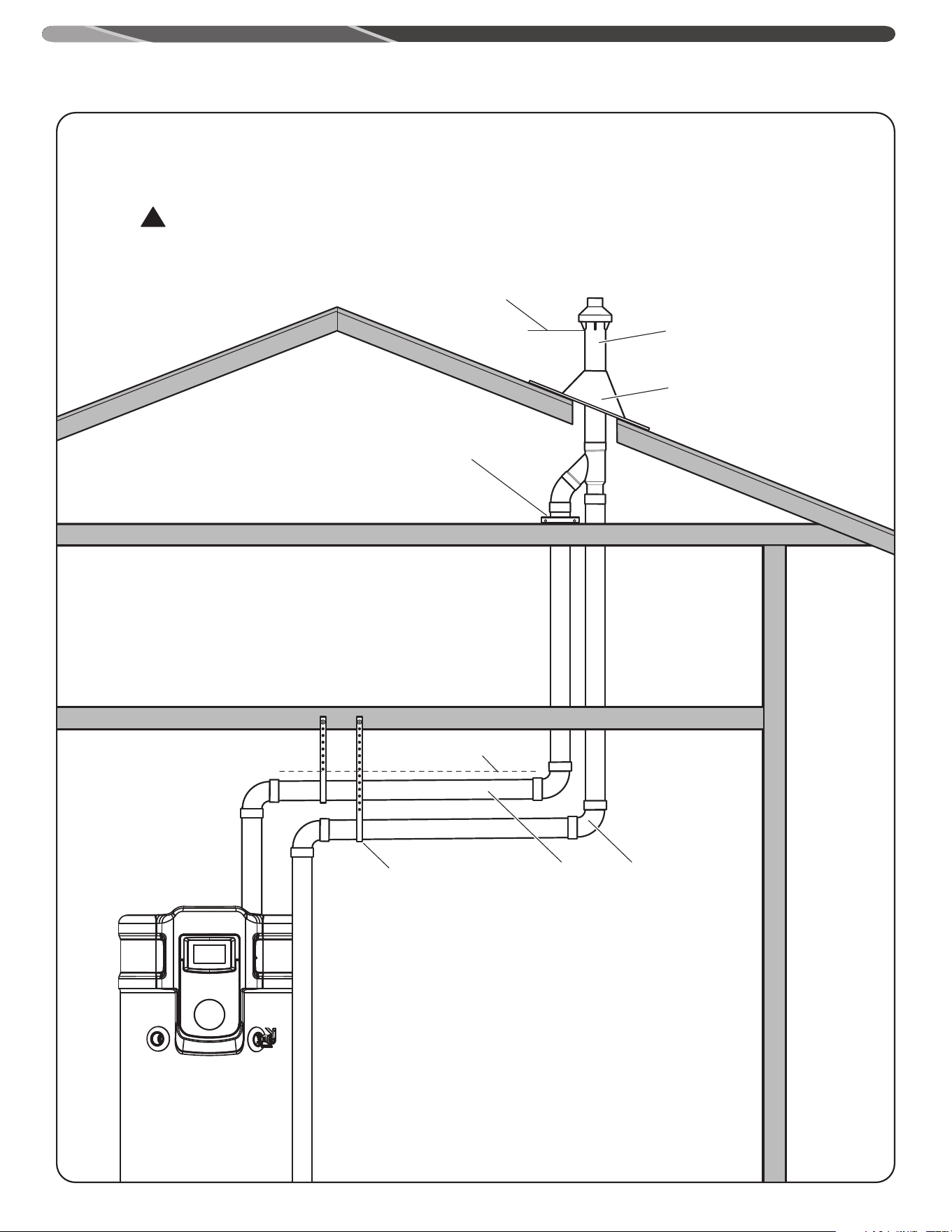
30
Alternative Vertical Vent Termination
Alternative vertical vent termination kits are commercially available. Please refer to the instruction sheet
packaged with the kit for complete installation instructions.
WARNING:
Under no circumstances should the exhaust pipe and the air intake pipe be connected together.
Support Hanger
Adjustable Roof Flashing
Support Clamp
Air Intake
Pipe
Exhaust Vent
Pipe
Minimum Clearance 18 inches above roof
Concentric Vent Termination
Upward slope 1/8” per foot
(10mm per meter) minimum
NOTE:
Ensure proper condensate management in all
vertical venting.
INSTALLATION
!
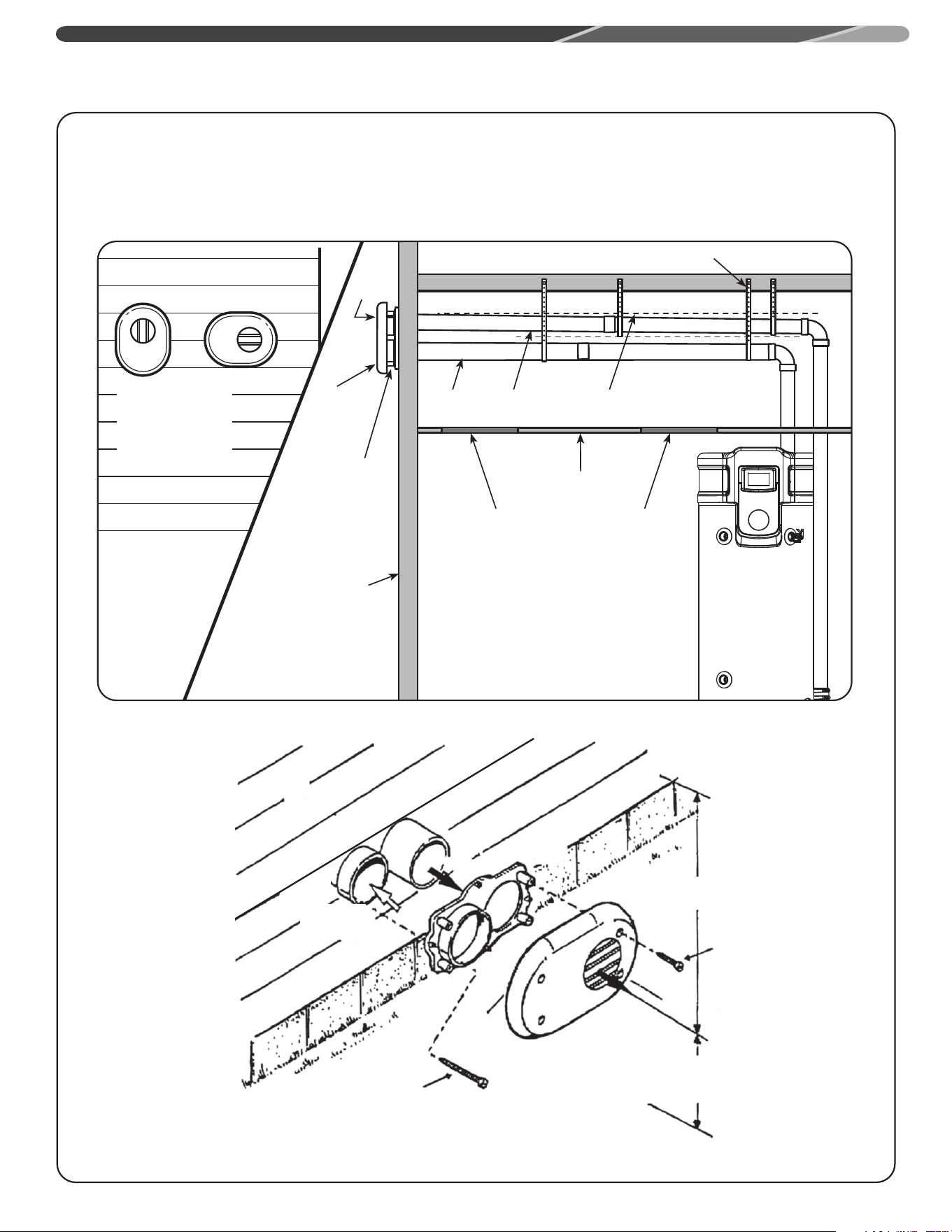
31
Alternative Horizontal Vent Installations
Alternative flat horizontal vent termination kits are commercially available for 2" and 3" pipes. Refer to
the instruction sheet packaged with the kit for complete installation instructions.
Flat Horizontal
Termination Kit
(this termination
can be rotated)
Exhaust
Vent
Flat
Termination
Kit
Air Intake
Vent
Wall
Air Intake
Pipe
Exhaust
Vent Pipe
Upward Slope
to Termination
Support Hanger
Inspection Access
Panel (Optional)
Inspection Access
Panel (Optional)
Ceiling
12" Minimum to
overhang
Maintain 12" minimum clearance above high-
est anticipated snow level or grade whichever
is greater
1" Screws
(4 req.)
2" Screws
(4 req.)
Vent
Vent
Cap
Vent
Plate
Vent
Combustion
Air
INSTALLATION
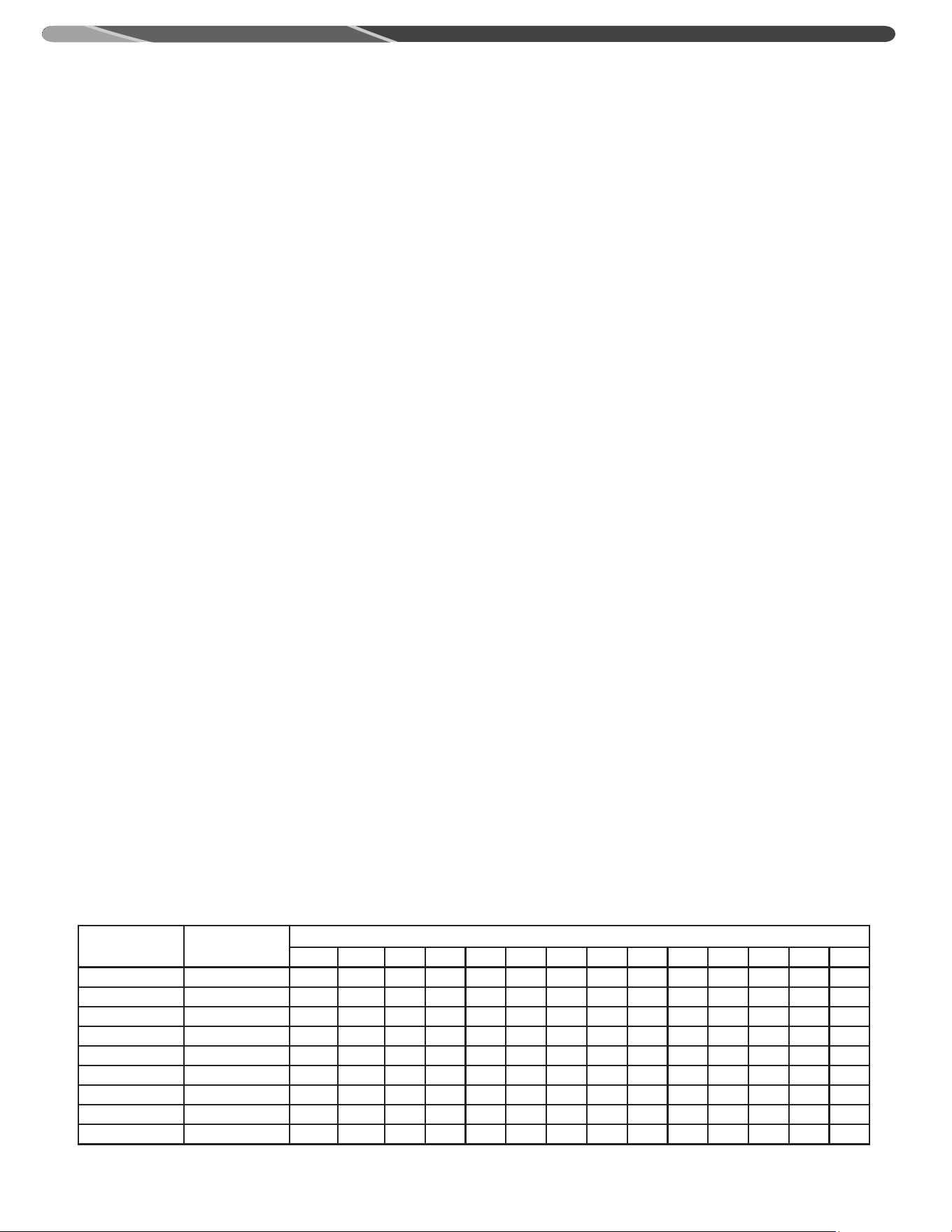
32
A. Water Heater Location
Close to vent locations
Located indoors and protected from freezing temperatures
Proper clearance from combustible surfaces
Air supply free of corrosive elements and flammable vapors
Sufficient room to service the heater
Water heater protected from water damage
B. Water Supply
Water heater completely filled
Air purged from water heater and piping
Water connections tight and free of leak
C. Gas Supply
Gas line equipped with shut-off valve, union, and sediment
trap
Minimum pipe size 1/2"
Soap and water solution used to check all
connections for gas leaks
Approved pipe joint compound used
D. Relief Valve
Discharge line run to open drain
Discharge line protected from freezing
E. Venting
Water heater vented separately from all other appliances
All vent and air intake pipe connections are secure
Vent and air intake pipes properly supported at regular
intervals
Precaution on taken to avoid moisture damage around vent
termination
Drain tube attached to noise reducer if needed. If not, ensure
cap is in place
F. Condensate
Condensate trap installed and primed.
Condensate neutralizer installed
G. Wiring
Correct power supply (120VAC)
Electrical connections are tight
Water heater is properly grounded with proper polarity.
INSTALLATION CHECK LIST
For maximum pipe capacity for installations in Canada, refer to CAN/CSA B149.1. For natural gas, refer to Tables A.1 through A.17. For propane (LP) gas, refer to Tables
B.1 through B.12.
Length Pipe Table
For U.S. Installations
Maximum Capacity of Pipe in Cubic Feet of Gas per Hour for Gas Pressures of 0.5 psig or Less and a Pressure Drop of 0.3 Inch Water Column
Based on a 0.60 Specific Gravity Natural Gas; If 1.5 Specific Gravity L.P. Gas is used, multiply capacity by 0.63
Nominal Iron Pipe Size
Inches
Internal Diameter
Inches
Length of Pipe, Feet
10 20 30 40 50 60 70 80 90 100 125 150 175 200
1/2 0.622 132 90 73 62 55 50 46 43 40 38 34 31 28 26
3/4 .824 278 190 152 130 115 105 96 90 84 79 72 64 59 55
1 1.049 520 350 285 245 215 195 180 170 160 150 130 120 110 100
1 1/4 1.380 1,050 730 590 500 440 400 370 350 320 305 275 250 225 210
1 1/2 1.610 1,600 1,100 890 760 670 610 560 530 490 460 410 380 350 320
2 2.067 3,050 2,100 1,650 1,450 1,270 1,150 1,050 990 930 870 780 710 650 610
2 1/2 2.469 4,800 3,300 2,700 2,300 2,000 1,850 1,700 1,600 1,500 1,400 1,250 1,130 1,050 980
3 3.068 8,500 5,900 4,700 4,100 3,600 3,250 3,000 2,800 2,600 2,500 2,200 2,000 1,850 1,700
4 4.026 17,500 12,000 9,700 8,300 7,400 6,800 6,200 5,800 5,400 5,100 4,500 4,100 3,800 3,500
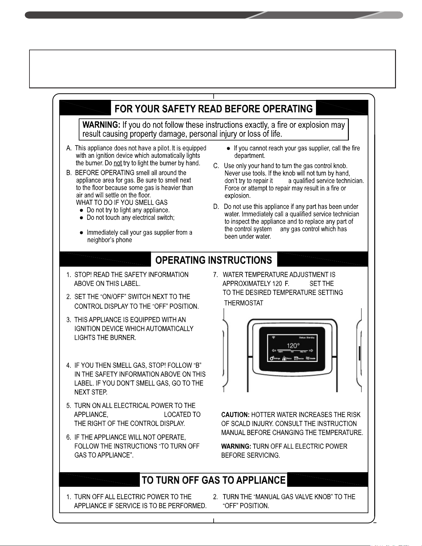
33
OPERATION
Before operating this water heater, be sure to read and follow the instructions on the label pictured below and all other labels and
warnings on the water heater and printed in this manual. Failure to do so can result in unsafe operation of the water heater resulting in
property damage, bodily injury, or death. Should you have any problems reading or understanding the instructions in this manual, STOP,
and get help from a qualified person.
Do not use
, and follow the gas supplier’s
WITH THE SWITCH
°
instructions.
any phone in your building.
. Call
or
(49°C.)
34
A. Do turn off manual gas shut-off valve if water heater has
been subjected to over heating, fire, flood, physical damage
or if gas supply fails to shut off.
B. DO NOT turn on water heater unless it is filled with water.
C. DO NOT turn on water heater if cold water supply shut-off
valve is closed.
D. DO NOT store or use gasoline or other flammable vapors and
liquids, such as adhesives or paint thinner, in vicinity of this
or any other appliance. If such flammables must be used,
open doors and windows for ventilation, and all gas burning
appliances in vicinity should be shut off, including their pilot
lights, to avoid vapors igniting.
NOTICE: Flammable vapors may be drawn by air currents from
surrounding areas to the water heater.
E. DO NOT allow combustible materials such as newspaper,
rags or mops to accumulate near water heater.
F. If there is any difficulty in understanding or following the
OPERATION or MAINTENANCE instructions, it is recommended
that a qualified person or serviceman perform the work.
WARNING:
Hydrogen gas can be produced in a hot water system
served by this water heater that has not been used for
a long period of time (generally two weeks or more).
HYDROGEN GAS IS EXTREMELY FLAMMABLE!! To dissipate
such gas and to reduce risk of injury, it is recommended that
the hot water faucet be opened for several minutes at the
kitchen sink before using any electrical appliance connected
to the hot water system. If hydrogen is present, there will
probably be an unusual sound such as air escaping through
the pipe as the water begins to flow. DO NOT smoke or use
an open flame near the faucet at the time it is open.
SAFETY PRECAUTIONS
1. TEMPERATURE SETTINGS — The temperature is adjusted
to the lowest setting when shipped from the factory. To meet
commercial water use needs, it is adjustable up to 185°F (85°C).
However, water temperatures over 125°F (52°C) can cause severe
burns instantly or death from scalds. This is the preferred starting
point for setting the control for supplying general purpose hot
water.
Safety and energy conservation are factors to be considered
when setting the water temperature. The most energy efficient
operation will result when the temperature setting is the lowest
that satisfies the needs consistent with the application.
DANGER:
Hotter water increases the potential for hot water SCALDS.
When this water heater is supplying general purpose hot
water requirements for individuals, a thermostatically
controlled mixing valve for reducing point of use water
temperature is recommended. Contact a licensed plumber or
the local plumbing authority for further information.
Outlet water temperature will vary during normal operating
cycles. Reliable temperature readings should be taken shortly
after main burner cycles off during a period of little or no use.
2. EMERGENCY SHUTDOWN —
WARNING:
Should overheating occur or the gas supply fail to shut off,
turn off the manual gas control valve to the appliance.
DO NOT use this appliance if any part has been under water.
Immediately call a qualified service technician to inspect the
appliance and to replace any part of the control system or any
gas control which has been under water.
If the water heater has been subjected to fire or physical damage,
turn off gas at the manual gas control (shut-off) valve. DO NOT
operate the water heater again until it has been checked out by a
qualified
service technician.
OPERATION
!
!
!
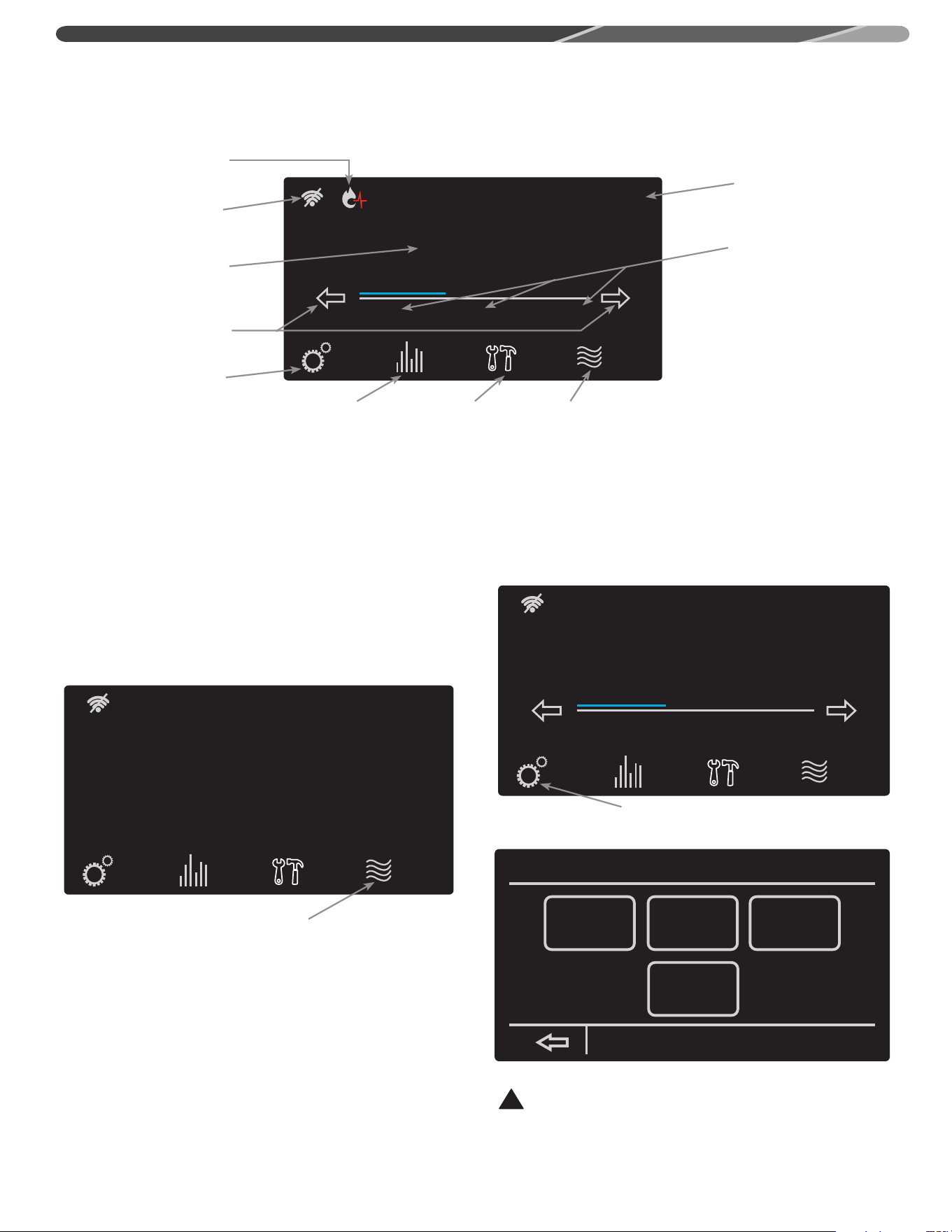
35
NAVIGATING THE HOME SCREEN:
Status: Standby
StatusSettings
warm hot very hot
Disable
120°
Service
Operating Status
Setting Menu
Button
Status Button
Service Menu
Button
Enable/Disable
Button
Rapid Temperature
Adjustment
Wifi Indicator
and Settings
Health Indicator
Icons
Temperature
Setting
Temperature
Adjustment
USER INTERFACE
STARTUP
Once power is applied to the water heater and the On button is
pressed, the Startup Wizard on the LCD will go over the below
features:
1. Setting of Time and Date
2. Setting Hours of Operation for the business
3. Wifi Setup
Follow the on-screen instructions to complete setup. Some of
these items can be skipped if a later setup is desired.
ENABLING (TURNING ON) THE UNIT
TEMPERATURE ADJUSTMENT
Tank temperature will be maintained according to the setting
on the home screen. If the water temperature setting needs
adjustment, use the arrows on the display to select desired
temperature.
The display also has a rapid temperature adjustment feature that
corresponds to the below temperature settings.
Warm: 110°F (43°C)
Hot: 140°F (49°C)
Very hot: 180°F (71°C)
Touching the text ‘warm’, ‘hot’, or ‘very hot’ will adjust the
temperature to the above temperature setting.
SETTING MENU
The settings function on the water heater display allows access
to the basic settings, configurations, schedules, and the time/
date.
Status: Water Heater Disabled
Water Heater Disabled
StatusSettings Enable
Service
Press the enable button to
turn the water heater on
Pressing the settings button will allow
access to water heater settings
Status: Standby
StatusSettings
warm hot very hot
Disable
120°
Service
settings
wifi setup
time/date
basic configs schedule
DANGER:
Hotter water increases the potential for hot water SCALDS.
!
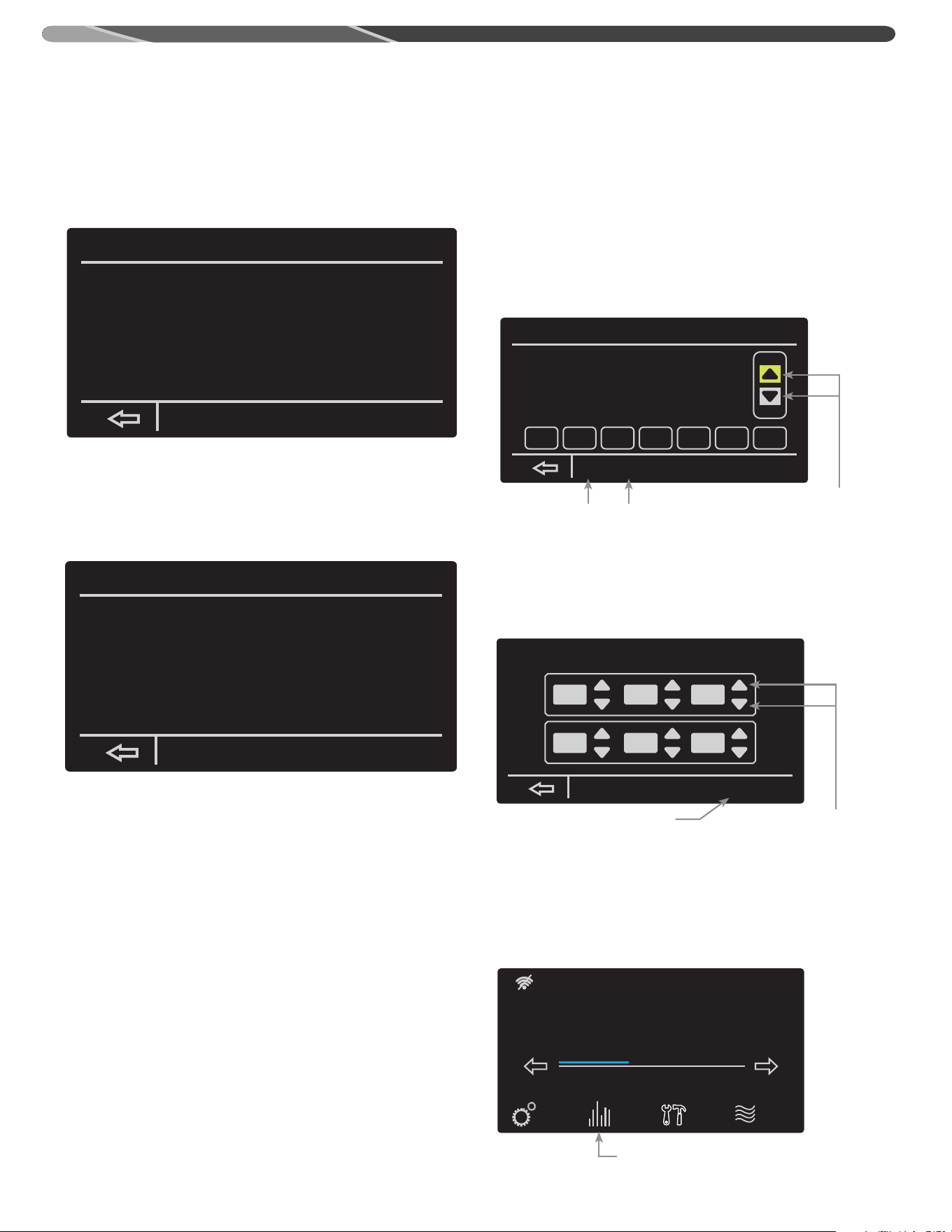
36
BASIC SETTINGS: The basic settings in your water heater can
allow you to change the temperature unit, screen adjustment
lock/unlock, enabling/disabling the alarm beep, and your EcoNet
network instance. Simply select the setting by tapping it, and
press the Up/Down arrows to make adjustments. WiFi setup can
be accessed from this screen as well.
CONFIGURATION SETTINGS: The configuration settings on your
water heater allows you to control the heating mode, setting the
recirculation pump, auxiliary input/output, enabling/disabling
modulation, and how your hot water heater reacts to a detected
leak.
The setting can be highlighted by tapping and then adjusted with
the up/down arrows.
Recirculation Pump Configuration can be set to the following:
Off - use this setting when the recirculation pump is not in use, or
not installed.
On - use this setting to manually turn on the pump. Useful for
testing the setup. Not recommended for general use.
Schedule - The recirculation pump will run on a 15 min On/15
min Off cycle whenever the heater is set to the "Home" mode
(see SCHEDULE SETTINGS). When the heater is in an Away mode,
the recirculation pump will not run.
On Demand - The recirculation pump can be triggered to run
from the mobile app. When triggered from the app, the pump will
run for 15 min.
This water heater has a modulation algorithm that can be
disabled by tapping ‘No’ in front of Modulation Disabled and
making adjustments by tapping the up/down buttons.
SCHEDULE SETTINGS: The schedule settings allows you to control
when your hot water heater will be enabled/disabled. Your heater
allows you to select a day you want and set the times when the
heater will be in use. You can also copy/paste the day you select
and apply it to other days as well.
TIME/DATE SETTINGS: By selecting time/date you can change the
water heaters current set time. You can also select the daylight
savings time function to automatically adjust the time for daylight
savings.
STATUS MENU
The Status screen provides information on the current operating
status, diagnostics and sensors. This screen also provides
information on the WiFi status.
basic settings
Temperature Display
Screen Adjustment Lock?
Beep On Alarm
EcoNet Network Instance
Elevation
Fahrenheit
No
Enabled
1
Normal
config settings
Shutoff Valve Config
Heating Mode
Recirc. Pump Config
Aux Output Select
When Leak Detected
Not Installed
Normal
On
Recirc. Pump
Alarm Only
schedule settings
Wed. Jan.11, 2:49 pm
Morning:
Night:
Mon.
08:00 am
06:00 pm
Time
Occupied
Occupied
Schedule
Tue.
copy
day
paste
day
cancel
Wed. Thu. Fri. Sat. Sun.
set to time and date
accept
D.S.T.
enabled
:
10 54 am
:
Jan. 11 2017
The up/down arrows enable
you to adjust the time of the
period run times.
By selecting a day and then accessing
the copy function, you can paste that
day’s settings onto other
The up/down arrows allow
you to control the time,
month, day, and year.
The D.S.T function allows you
to adjust the time for daylight
savings time.
USER INTERFACE
By pressing the Status button, you will be
taken to a prompt showing the state of your
water heater’s many features.
Status: Standby
StatusSettings
warm hot very hot
Disable
120°
Service
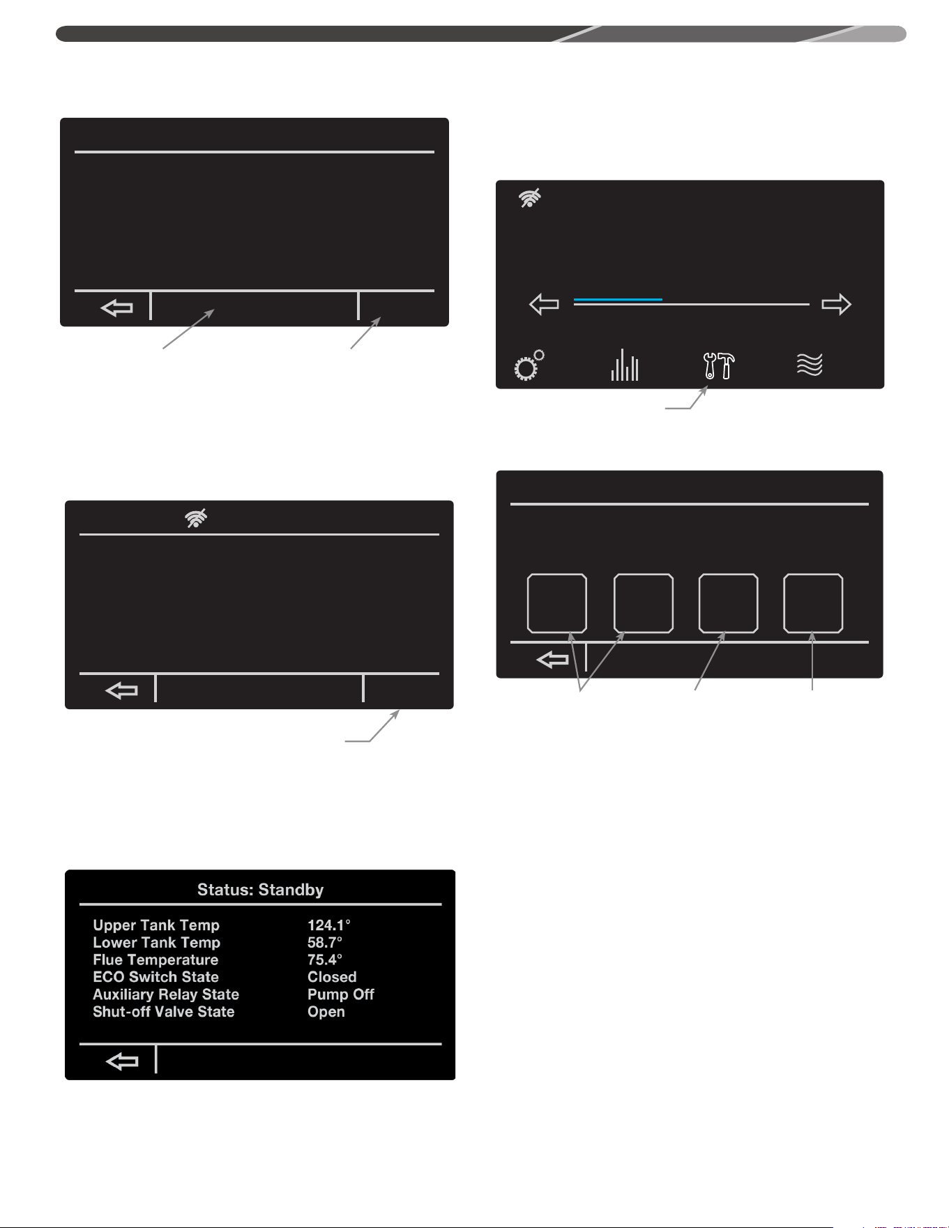
37
service
Product Model Number:
Product Serial Number:
Software Version Number: WH-DRG1-00-00-86
current
alarms
alarm
history
system
health
service
alerts
WI-FI STATUS: After selecting the Wi-Fi status function, you will
be brought to a prompt showing you the current state of your
water heater’s Wi-Fi and the ability to set-up your water heater’s
Wi-Fi.
MORE FUNCTION: Selecting the more function your heater will
bring you to a prompt showing you the current temperatures of
the lower/upper tank, Flue temperature, ECO switch state, and
Auxiliary relay state.
SERVICE MENU
The service screen provides information on the product
description, alarms, system health, and service alerts. Alarm
details can be found in the "Before You Call Service" section of
the manual.
In case there is an active alarm, the "Service" button will blink
on the home screen. Pressing the "Service" button will show a
new screen containing the active alarms and alarm history.
By selecting the service function,
you will be taken to a prompt
giving you access to the heater’s
alarms, health, and alerts.
By selecting Wi-Fi status, you can
access the status of your water
heater’s Wi-Fi and even set it up.
By selecting more, you can
access the temperatures of your
water heater, ECO switch state,
and auxiliary switch state.
Selecting the Wi-Fi setup function will bring you
to a prompt allowing you to connect your water
heater to your home Wi-Fi.
Current Alarms and Alarm
History allows you to
access any current alarms
that have been tripped
and view a list of previous
alarms.
System Health
will show you the
status of the tank’s
combustion health
and overall tank
health.
Service Alerts will allow
you to set how often you
want to be alerted to
check venting, clean the
drain trap, replace the
neutralizer, and to drain
and inspect the tank.
Status: Standby
StatusSettings
warm hot very hot
Disable
120°
Service
Status: Water Heater Disabled
Air Intake Press. Switch
Exhaust Press. Switch
Current Fan Speed
Flame Current
Closed
Closed
0RPM
0.0 uA
morewifi status
wifi status
WiFi Device Status............
WiFi Signal Strength [dBm]....
Econer wifi SW Version........
WiFi Module SW Version........
MAC Address...................
SSID..........................
IP Address ...................
Subnet Mask...................
Gateway.......................
Ready To Connect
0
RH-WIFI-02-01-05
14.76.36.P103
F0-03-8C-B3-C6-CC
wifi setup
USER INTERFACE
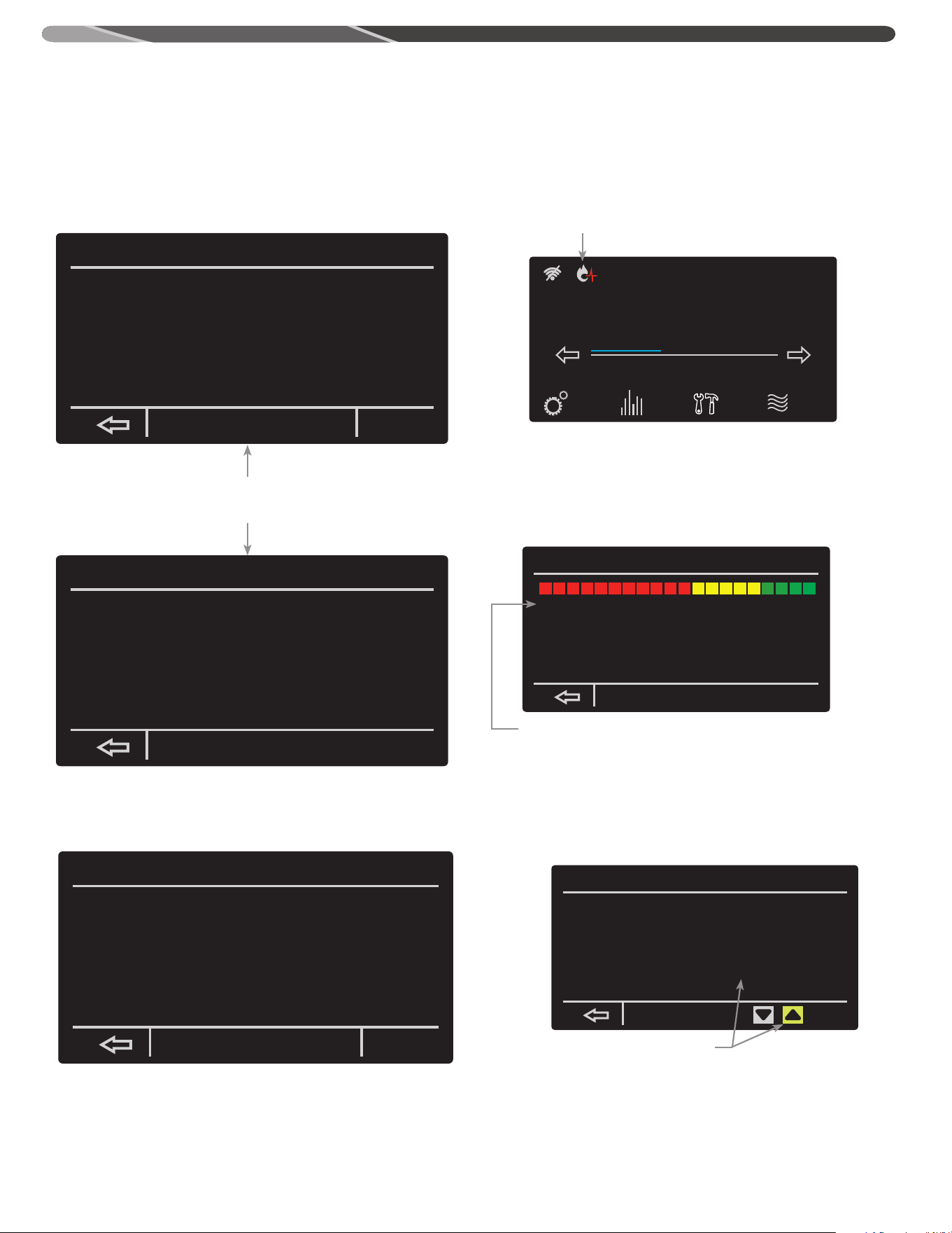
38
ALARMS: The current alarms function allows you to see any
problems that have been detected by your water heater. Also, by
selecting on the current alarm you can press “more info” to read
more on the current problem of your water heater. Alarm history
allows you to see any of the previous alarms that have gone off
in the past and give you the ability to clear those previous alarms.
ALARM HISTORY: The alarm history function allows you to see
the previous alarms that have been detected by your water
heater in the past.
SYSTEM HEALTH: The system health function allows you to see
the current health of your hot water heater’s combustion health.
The combustion health has three levels of health:
SERVICE ALERTS: By selecting the Service alerts function you will
be able to adjust how often you want to be alerted to drain and
inspect the tank, clean the drain trap, check the venting, and to
replace the neutralizer.
current alarms
A007 Exhaust Switch open. Check Wiring/Venting
more
info
clear
service alerts
Drain & Inspect Tank:
Check Venting:
Clean Drain Trap:
Replace Neutralizer:
Enabled
Enabled
Enabled
Enabled
9 months
6 months
1500 hours
1500 hours
9.0 left
6.0 left
1500 left
1500 left
By selecting “more info” you
can be given a more in-depth
explanation of the current alarm.
This symbol will appear on your home
screen if your combustion health is
critical. Pressing this icon will take the
user to the Health Status Screen
By selecting an option and then using the up
and down arrow, you can set how often you’d
like to be alerted to system maintenance.
Trouble-Shooting
A007 Exhaust Switch open. Check Wiring/Venting
Check switch wiring and venting. If problem
persist, please contact technical support or
service provider.
alarm history
14:48:13 01/11/17 A007 Echaust Switch open. Check wiring/venting
clear
COMBUSTION HEALTH:
1. Normal operation - no action needed
2. Begin planning for service and/or replacement.
3. Needs Servicing - contact your service provider
Status: Standby
StatusSettings
warm hot very hot
Disable
120°
Service
The health of your system’s combustion system and overall health
can be seen here. This screen be accessed by tapping the health
indicator icons on the home screen.
system health
(typical 10K cyc/yr)
(typical 2K hrs/yr)
Combustion Health Status: Operating Normally
Lifetime Heating Cycles:
Lifetime Run Time Hours:
1
0.0
baseline init
USER INTERFACE
39
Properly maintained, this water heater will provide years of
dependable, trouble free service. It is strongly
suggested that a regular routine maintenance program be
established and followed by the owner. It is further recommended
that a periodic inspection of the relief valve and venting system
should be made by service technicians qualified in gas appliance
repair.
1. ROUTINE PREVENTIVE MAINTENANCE
A. PRESSURE SWITCH — Inspect the inlet to the
pressure switch and the tubing for debris or
blockage. Clean out the tubing periodically to
prevent buildup of debris.
B. CONDENSATE TRAP — Check for blockages.
C. ELECTRICAL CONNECTIONS — Periodic inspection of all
electrical connections and wiring conditions.
CAUTION:
Label all wires prior to disconnection when servicing
controls. Wiring errors can cause
improper and dangerous operation.
CAUTION:
VERIFY PROPER OPERATION AFTER SERVICING !
Make certain all power to the water heater is turned "OFF" before
performing any maintenance or inspection work on this water
heater.
Before manually operating the relief valve, make certain no one
will be exposed to the danger of coming in contact with the hot
water released by this valve. The water may be hot enough to
create a SCALD hazard. The water released should be directed to
a suitable drain to prevent injury or damage.
NOTICE: If the temperature and pressure relief valve on the
water heater discharges periodically, this may be due to
thermal expansion in a “closed” water system. Contact the
water supplier or local plumbing inspector on how to correct
this. DO NOT plug the relief valve outlet.
E. TANK— Good maintenance requires that the tank be cleaned
of deposits. Unless the water supply is soft (0 to 5 grains
hardness), scale or lime deposits will accumulate in the tank.
Hard water scale is deposited at an increasingly high rate in
proportion to increased water temperature. Accumulation of
these deposits may reduce efficiency, and shorten the life of
the water heater.
Drain a few quarts of water from the water heaters tank every
month to clean the tank off these deposits
F. SEASONAL OPERATION - If the water heater is to remain idle
for an extended period (60 days or more) the heater should
be turned off. The water heater and piping should be drained
if they might be subjected to freezing temperatures. It is
recommended that the water heater's operation is thoroughly
checked (by a qualified service technician) before it is placed
back in service. NOTICE: Refer to the Hydrogen Gas
caution notation on "Safety Precautions" section of this
manual. It is suggested that a few quarts of water be drained
from the water heater's tank every month to clean the tank of
these deposits.
G. VENTING SYSTEM — Inspect the venting system at least yearly
to make certain the passageways are free and unobstructed,
and that the vent connector from the water heater’s blower
assembly is properly positioned and securely attached.
Remove any obstructions in the vent connector or vent
terminal.
MAINTENANCE
!
!
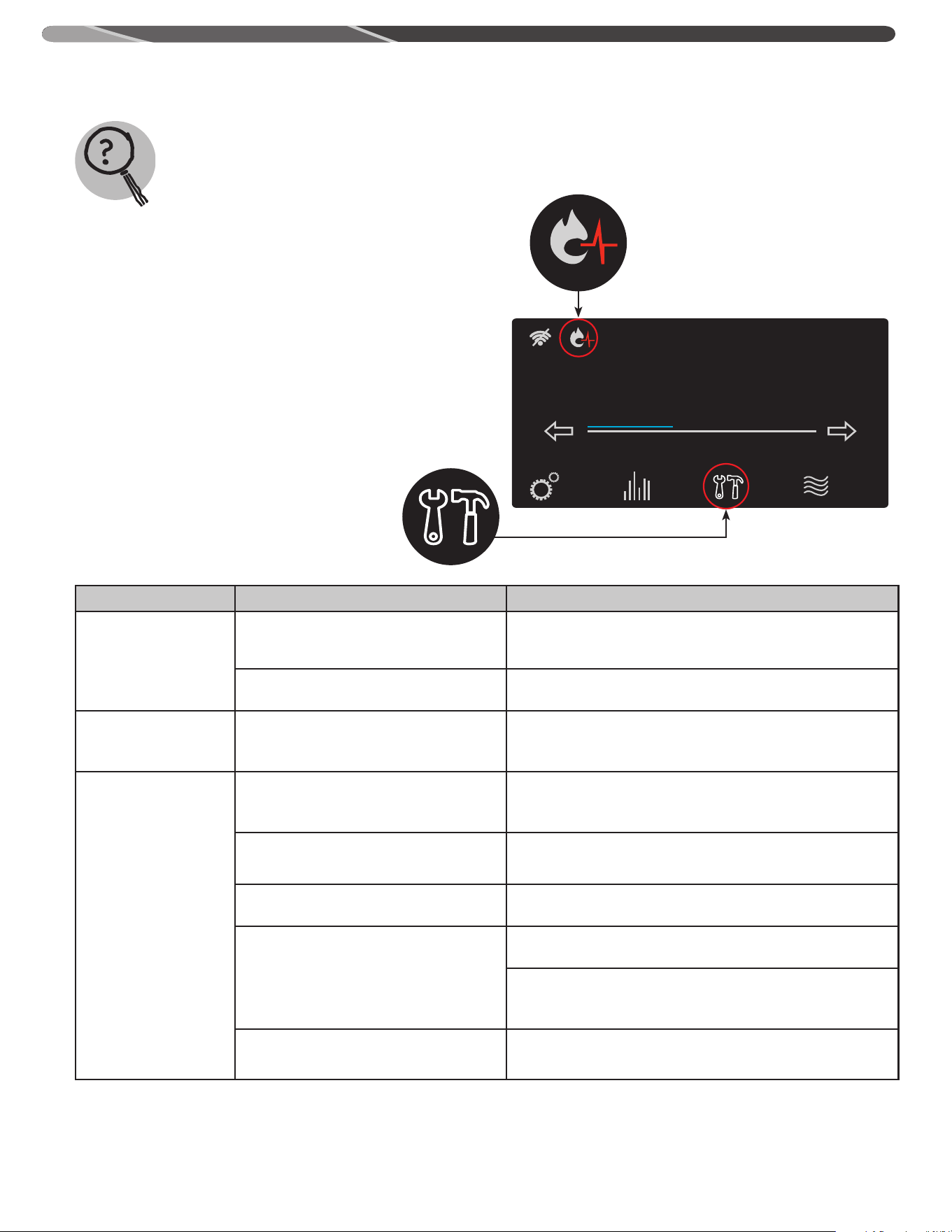
40
Troubleshooting Tips
Save time and money! Review the charts on the following pages first and you may not need to call for service.
Problem Possible Causes What To Do
Display not on
No power to the unit
Check the breaker to the unit, the on/off switch, and the fuse on
the ignition control board.
Harness from control board disconnected Make sure that the wire harness to J4 on the ignition control
board is still connected.
Blower does not run No power to blower motor Verify power to the control board and that all harnesses to
the blower are properly installed. Make sure that there is no
damage the harnesses or connectors.
Unable to light
the main burner
Air in gas line Let the unit cycle at least 3 times to remove air from the gas
line. If the unit does not try to light, contact a qualified service
technician to purge the air from the gas line.
Manual gas shut-off
valve(s) not open
Check to make sure that all manual shut-off valves between the
unit and the gas line are open.
Blocked inlet or exhaust vent pipe Contact a qualified service technician to evaluate vent pipes for
a blockage.
Pressure switch
Make sure the pressure switch hoses are not "kinked" or
disconnected.
Blocked inlet or outlet vent systems will cause pressure switch
to shut off the unit. Contact a qualified service technician to
evaluate the vent system.
Wire connection not fully secured Contact a qualified service technician to confirm wire
connections.
Status: Standby
StatusSettings
warm hot very hot
Disable
120°
Service
If one of the health indicators is blinking on the home screen or
the service icon is blinking there is an issue with the operation of
your water heater. Pressing the service icon will allow you to look
at Current Alarms (and Alerts), Alarm History, and Unit Health
screens for issues that need attention. Pressing the blinking
health indicator will show the health screen.
Status: Standby
StatusSettings
warm hot very hot
Disable
120°
Service
Status: Standby
StatusSettings
warm hot very hot
Disable
120°
Service
BEFORE YOU CALL FOR SERVICE…
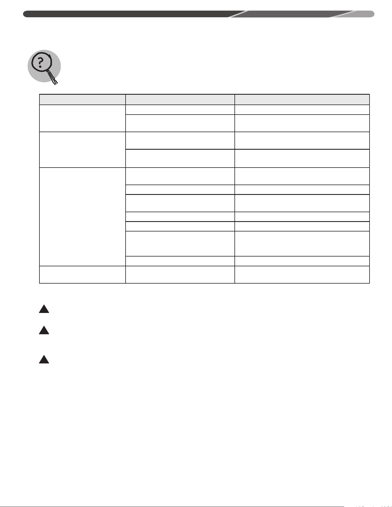
41
BEFORE YOU CALL FOR SERVICE…
Troubleshooting Tips
Save time and money! Review the charts on the following pages first and you may not need to call for service.
Problem Possible Cause What To Do
Unable to light
the main burner
Gas control problem Contact a qualified service technician.
Unit or electrical supply line not properly
grounded
Verify that the electrical supply line and unit have
proper ground connection.
Main burner does not stay lit
Burner flame not contacting sensor rod.
Call a qualified service technician to review flame
rectification.
Unit or electrical supply line not properly
grounded
Verify the electrical supply line and unit have proper
ground connection.
Not enough or no hot water
Water usage exceeded the capacity
Wait for the water heater to recover after an
abnormal demand of the water heater.
Low gas pressure Check the gas supply pressure.
Water heater set point is set too low
See the "User Interface" section of this manual to
the set point temperature.
Leaking or open hot water faucets Make sure all faucets are closed.
"ON/OFF" switch turned off Turn the switch to the "ON" position.
Colder supply water
Incoming water temperature might be lower than
when the unit was initially installed. This will require
a longer heat up cycle.
Burner not staying on Refer to the "Main Burner" section of this manual.
Water is too hot The water heater set point is set too high
See the "User Interface" section of this manual to
the set point temperature.
CAUTION:
Make certain power to the water heater is “OFF” before removing the protective cover FOR ANY REASON.
CAUTION:
Label all wires prior to disconnection when servicing controls. Wiring errors can cause improper and dangerous operation.
VERIFY PROPER OPERATION AFTER SERVICING!
CAUTION:
For your safety, DO NOT attempt repair of gas piping, gas control burner, vent connectors or other safety devices. Refer repairs to
qualified service personnel.
NOTE: A Training Manual is available through the Technical Services Department for a more detailed troubleshooting and repair guide.
!
!
!
42
Alarm (‘A’)
and Alert
(‘T’) Codes
Description Current Alarm Screen Display
A001
Ignition lockout due to a total of 9 consecutive failed
ignitions. This will disable the heater.
A001 Ignition lockout.
->Clear error code by turning the unit off/on. If
problem persists, contact technical support or service
provider.
A002
Flame not stable lockout. Lost flame three times during
one heat cycle. This will disable the heater.
A002 Flame is not stable.
->Clear error code by turning the unit off/on. If
problem persists, contact technical support or service
provider.
A003
The intake pressure switch was detected open when the
blower was running. This will disable the heater.
A003 Intake Switch open. Check Wiring/Venting
->Check switch wiring and venting. If problem
persists, contact technical support or service provider.
A004
The proof of air flow switch was detected open during
heating operation. This will disable the heater.
A004 PoF Switch error H. Check Blower/Wiring.
->Check switch wiring and venting. If problem
persists, contact technical support or service provider.
A005
The proof of air flow switch was detected open during
pre-purge operation. This will disable the heater.
A005 PoF Switch error E. Check Blower/Wiring.
->Check switch wiring and venting. If problem
persists, contact technical support or service provider.
A006
The proof of air flow switch was detected open during
post purge operation.
A006 PoF Switch error P. Check Blower/Wiring.
->Check switch wiring and venting. If problem
persists, contact technical support or service provider.
A007
Exhaust flue pressure switch was detected open during
heating. This will disable the heater.
A007 Exhaust Switch open. Check Wiring/Venting
->Check switch wiring and venting. If problem
persists, contact technical support or service provider.
A008
The proof of air flow pressure switch was detected
closed before the blower started operation. This will
disable the heater.
A008 PoF Switch/Blower mismatch. Call Tech Svc
->The Proof of Fan pressure switch is closed when
the blower is off. Contact technical support or service
provider.
A010 Ignition Control Test Failure during End of Line (EOL) test
A010 Ignition Control Test Failure
-> End of Line (EOL) test failure. Unit disabled.
BEFORE YOU CALL FOR SERVICE…
43
BEFORE YOU CALL FOR SERVICE…
Alarm (‘A’)
and Alert
(‘T’) Codes
Description Current Alarm Screen Display
A012 Flame Detected During Standby/Disabled Mode
A012
Clear error code by turning the unit off and on. If
problem persists contact technical support or service
provider
A016
Energy Cutout (ECO) switch is open. This will disable
the heater.
A016 High Tank Temperature. Call Tech Service.
->Clear error code by pressing clear button. Refer
to use and care manual for troubleshooting, or contact
technical support.
A017
Flue (exhaust) gas temperature has exceeded 155°F.
This will disable the heater.
A017 High Flue Temp. Recycle unit ON/OFF.
->Blower will continue to run until exhaust
temperature has decreased. If problem persists contact
technical support.
A018
Flue temperature sensor (thermistor) detected open.
This will disable the heater.
A018 Flue Temp Sensor open. Check wiring.
->Check wiring to sensor. If condition persists refer
to use and care manual or contact technical support.
A019
Flue temperature sensor (thermistor) detected short
circuited. This will disable the heater.
A019 Flue Temp Sensor shorted. Call Tech Svc.
->Check wiring to sensor. If condition persists refer
to use and care manual or contact technical support.
T020
Lower tank (inlet) temperature sensor (thermistor)
detected open.
T020 Lower Tank Sensor open. Check wiring.
->Check wiring to sensor. If condition persists refer
to use and care manual or contact technical support.
T021
Lower tank (inlet) temperature sensor (thermistor)
detected short circuited.
T021 Lower Tank Sensor shorted. Call Tech Svc.
->Check wiring to sensor. If condition persists refer
to use and care manual or contact technical support.
A022
Upper tank temperature sensor detected open. This will
disable the heater.
A022 Upper Tank Sensor open. Check wiring.
->Check wiring to sensor. If condition persists refer
to use and care manual or contact technical support.
A023
Upper tank temperature has exceeded 205°F. This will
disable the heater.
A023 Upper Tank temp. too hot. Call Tech Svc.
->Clear error code by pressing clear button. Refer
to use and care manual for troubleshooting, or contact
technical support.
A024
Upper tank temperature sensor detected short circuited.
This will disable the heater.
A024 Upper Tank sensor shorted. Call Tech Svc.
->Check wiring to sensor. If condition persists refer
to use and care manual or contact technical support.

44
BEFORE YOU CALL FOR SERVICE…
Alarm (‘A’)
and Alert
(‘T’) Codes
Description Current Alarm Screen Display
A025
Control does not detect blower RPM. This will disable
the heater.
A025 No Blower RPM feedback. Call Tech Service
->Contact technical support or service provider.
A026
Blower RPM feedback (actual RPM) is ≥300 RPM from
desired RPM for > 1 minute.
A026 Blower expected RPM vs actual RPM mismatch
->Contact technical support or service provider.
A027
Flame current detected prior to opening gas valve. This
will disable the heater.
A027 Flame present before ignit. Call Tech Svc
->Clear error code by turning the unit off and on. If
problem persists contact technical support or service
provider.
A028
Flame current detected 10 seconds after closing gas
valve. This will disable the heater.
A028 Flame present w/o heating. Call Tech Svc.
->Clear error code by turning the unit off and on. If
problem persists contact technical support or service
provider.
T029 Unit did not light. T029 Failed ignition. Retrying.
A030 Unit lost flame. A030 Flame lost during heating. Retrying.
T032 Lower (inlet) thermistor analog to digital converter fault.
T032 Lower Tank temp A/D error. Call Tech Svc.
->If problem persists, contact technical support or
service provider.
A033
Exhaust flue thermistor analog to digital converter fault.
This will disable the heater.
A033 Flue sensor A/D error. Call Tech Service.
->If problem persists, contact technical support or
service provider.
A034
Upper tank thermistor analog to digital converter fault.
This will disable the heater.
A034 Upper Tank temp A/D error. Call Tech Svc.
->If problem persists, contact technical support or
service provider.
T035
Gas relay #1 contacts did not close. The unit will
continue to try and close the relay to initiate combustion.
T035 Gas Relay 1 stuck open. Call Tech Service
->If problem persists, contact technical support or
service provider.
A036
Gas relay #1 stuck closed. This could inadvertently allow
the gas valve to open. This will disable the heater.
A036 Gas Relay 1 stuck closed. Call Tech Svc.
->If problem persists, contact technical support or
service provider.
A037
Gas relay #2 contacts failed to properly close. This can
cause gas valve cycling and gas buildup in the burn
chamber. This will disable the heater.
A037 Gas Relay 2 stuck open. Call Tech Service
->If problem persists, please contact technical
support or service provider.
45
BEFORE YOU CALL FOR SERVICE…
Alarm (‘A’)
and Alert
(‘T’) Codes
Description Current Alarm Screen Display
A038
Gas relay #2 stuck closed. This could inadvertently allow
the gas valve to open. This will disable the heater.
A038 Gas Relay 2 stuck closed. Call Tech Svc.
->If problem persists, contact technical support or
service provider.
A039
This is a control board hardware fault and requires
control board replacement if persistent. This will
disable the heater.
A039 Flame sense cct fault. Call Tech Service
->If problem persists, contact technical support or
service provider.
A040
This is a control board hardware fault and requires
control board replacement if persistent. This will
disable the heater.
A040 Controller RAM fault. Call Tech Service.
->If problem persists, contact technical support or
service provider.
A041
This is a control board hardware fault and requires
control board replacement if persistent. This will
disable the heater.
A041 Controller ROM fault. Call Tech Service.
->If problem persists, contact technical support or
service provider.
A042
This is a control board hardware fault and requires
control board replacement if persistent. This will
disable the heater.
A042 Controller EEPROM fault. Call Tech Svc.
->If problem persists, contact technical support or
service provider.
A043
This is a control board hardware fault and requires
control board replacement if persistent. This will
disable the heater.
A043 IC Program execution fault. Call Tech Svc
->If problem persists, contact technical support or
service provider.
A044
Input power frequency not 60 Hz. (outside allowable
deviation). This will disable the heater.
A044 Processor Clock/Line Frequency Disagree
->If problem persists, contact technical support or
service provider.
A101
This is a display board hardware fault and requires
control board replacement if persistent. This will
disable the heater.
A101 Configuration Data Restore Failure
->Initialization of the control system failed at
startup. Contact technical support or service provider.
A102 Set the internal clock time.
A102 Time Clock needs to be programmed
->Go to Settings, select time/date menu and set the
time and date.
A103
This is a display board hardware fault and requires
control board replacement if persistent. This will
disable the heater.
A103 Time Clock not advancing time properly
->Contact your qualified service provider.
A104
Presence of water detected by the leak sensor in the
bottom pan. If water is seen locate source and take
appropriate action to correct the issue. This may disable
the heater based on configuration settings.
A104 Water Leak Detected
->The presence of water has been detected by the
control. Contact a qualified service provider.
46
Alarm (‘A’)
and Alert
(‘T’) Codes
Description Current Alarm Screen Display
T105
Check to see if leak sensor is installed in the bottom
pan. Check wiring on connector P11 of the ignition
control board.
T105 Water Leak Sensor Not Installed
->Check water leak sensor connection. Refer to
use and care manual for troubleshooting, or contact
technical support.
A108
Communication lost between the display board and the
ignition control board. The ignition control board will
continue to operate the heater using the last known
configuration settings. Check wiring between the display
and P5 of the ignition control board.
A108 Ignition Board Communication Failure
->Communications lost with ignition control board.
If problem persists, contact technical support or service
provider.
A110
Monthly test of automatic shutoff valve (premium
models only) was not completed properly. The valve did
not close in the allotted time.
A110 Shutoff Valve Test Close Error
->Auto Shutoff valve failed to close during test cycle.
Please contact technical support or service provider.
A111
Monthly test of automatic shutoff valve (premium
models only) was not completed properly. The valve
did not open in the allotted time. This will disable the
heater.
A111 Shutoff Valve Test Open Error
->Water heater has been disabled. Manually open
valve. Please contact technical support or service
provider.
A112
Automatic shutoff valve (premium models only) is
closed. This will disable the heater.
A112 Shutoff Valve Not Open: Heating Disabled
->Manually open valve if no water detected or if
unit is not being serviced. Contact technical support or
service provider.
T113
Peak flame rod current has deviated from the startup
average. This is indicative of degradation of the flame
rod (dirty, sooty). It needs to be cleaned and inspected .
T113 Flame Rod Degraded and Needs Servicing
->Clean or replace per use and care manual. Please
contact technical support for assistance.
T114
Peak flame rod current has deviated from the startup
average by a significant amount. Clean and inspect
flame rod. Replace if necessary.
T114 Flame Rod Degraded and Needs Servicing
->Clean or replace per use and care manual. Please
contact technical support for assistance.
T115
Monitored characteristics of the combustion system
indicate degraded performance. Combustion system
needs to be inspected and serviced.
T115 Combustion Health Degraded: Needs Service
->Combustion system performance is degraded.
Please contact technical support or service provider for
assistance.
T116
Monitored characteristics of the combustion system
indicate severely degraded performance. Combustion
system needs to be inspected and serviced.
T116 Combustion Health Degraded. Needs Service
->Clear error code by pressing clear button. Refer
to use and care manual for troubleshooting, or contact
technical support.
T117
Periodic maintenance, inspection, and upkeep on the
unit.
T117 Time to Drain and Inspect Tank
->Refer to the use and care manual for instructions,
or contact technical support or service provider.
BEFORE YOU CALL FOR SERVICE…
47
Alarm (‘A’)
and Alert
(‘T’) Codes
Description Current Alarm Screen Display
T118
Periodic maintenance, inspection, and upkeep on the
unit.
T118 Time to Check Venting for Debris
->Refer to the use and care manual for information,
or contact technical support or service provider.
T119
Periodic maintenance, inspection, and upkeep on the
unit.
T119 Time to Clean Out the Condensate Drain Trap
->Refer to the use and care manual for instructions
and locations. Call technical support or service provider
if necessary.
T120
Periodic maintenance, inspection, and upkeep on the
unit.
T120 Time to Replace the Neutralizer
->Clear error code by pressing clear button. Refer
to use and care manual for troubleshooting, or contact
technical support.
A143
The switch information on the Shutoff Valve is indicating
incorrect information such as both switches are OPEN or
both switches are CLOSED.
A143 Shutoff Valve Inputs in Error
->Manually open valve if no water detected or if
unit is not being serviced. Contact technical support or
service provider.
A200
Software versions between the Display Control and
Ignition Control are incompatible.
A200 Incompatible Ignition Control/Display Error
->The ignition control and display are incompatible
with each other. Contact technical support.
T504
WiFi chip communication timing error. This doesn't
mean the chip has failed.
T504 Wifi Chip Communication Error
->Refer to the use and care manual for information,
or contact technical support or service provider or
Enercare.
BEFORE YOU CALL FOR SERVICE…
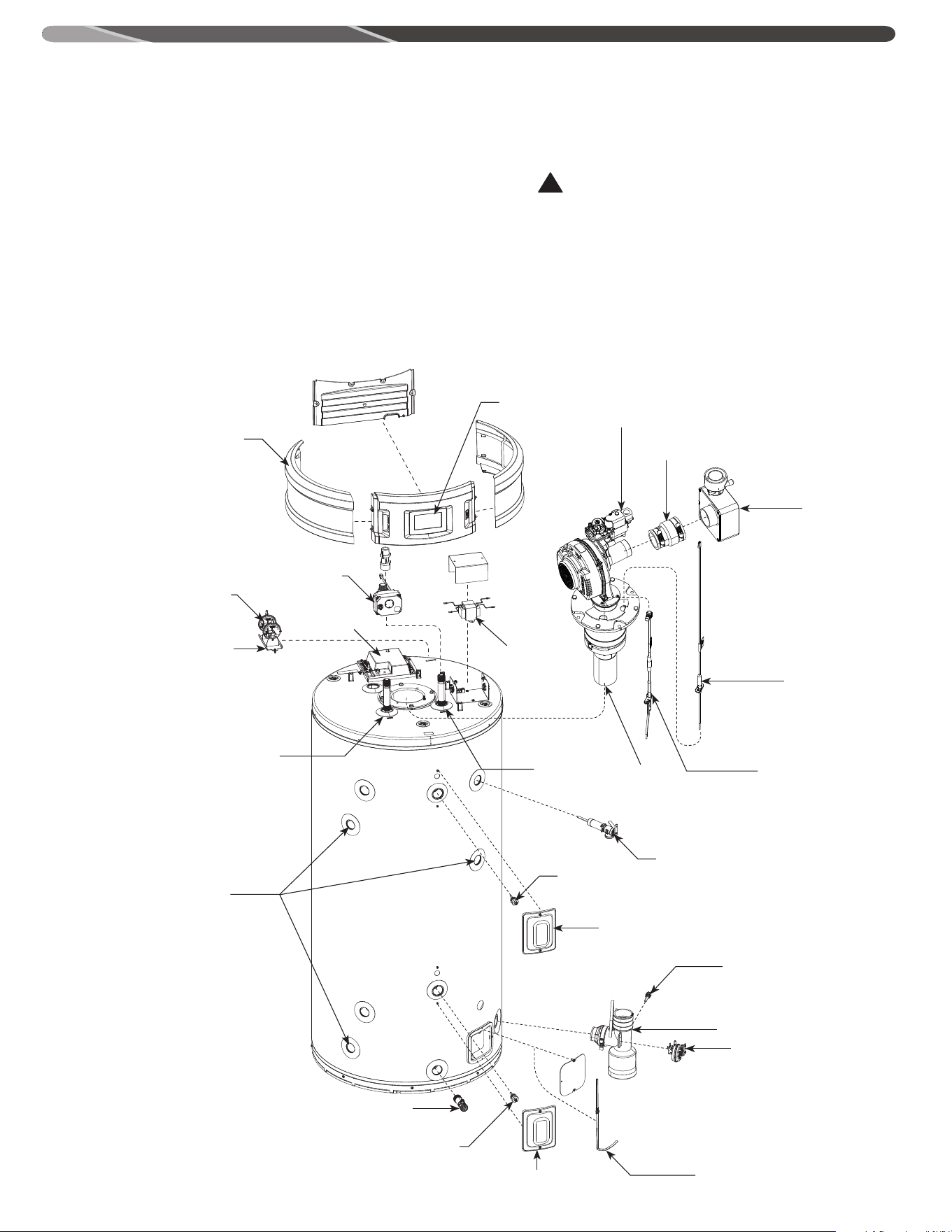
48
REPLACEMENT PARTS
Instructions For Placing a Parts Order
All parts orders should include:
The model and serial number of the water heater
from the rating plate.
Specify type of gas (natural or LP) as marked on
the rating plate.
Part description (as noted below) and number of
parts desired.
CAUTION
For your safety DO NOT attempt repair of gas piping, gas
control burner, vent connectors or other safety devices.
Refer repairs to qualified service personnel.
!
Ignition Control
Flame Sensor
Display
Gas Valve
Blower
Spark Igniter
Burner
Noise Reducer
Side Panel
Transformer
Outlet Heat
Trap
Drain Valve
Condensate Drain
Lower Thermistor
Temperature Sensor
Upper Thermistor / ECO
Temperature and Pressure Relief Valve
Inlet Heat
Trap
Intake Pressure
Switch
Anode
Proof
of Fan
Switch
Auto Shut
Off and Flow
Sensor
Exhaust Pressure Switch
Upper Thermistor Cover
Lower Thermistor Cover
Leak Sensor
Rubber Connector
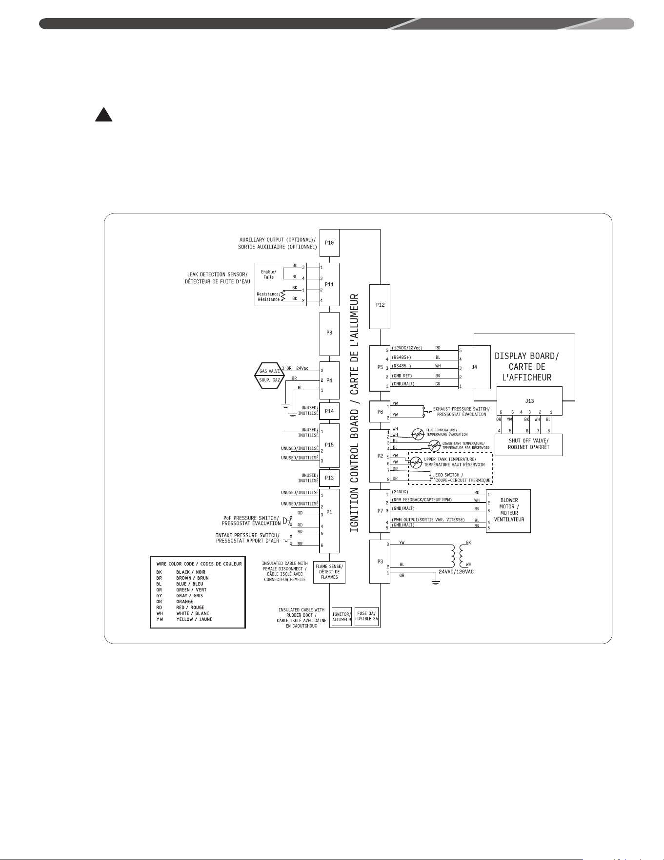
49
!
WIRING AND SCHEMATIC DIAGRAMS
AX6078
WARNING
NOTICE: DO NOT use in conjunction with a GFCI. To avoid the risk of fire, explosion or asphyxiation from carbon monoxide,
NEVER operate this water heater unless it is properly vented and has an adequate air supply for proper operation. It is
important that the vent pipe engages fully into any pipe fitting and be kept in that position until the adhesive has fully
cured. DO NOT drill or punch holes in the plastic pipe or fittings.

50
NOTES

51
NOTES

52
1. Should you have any questions about your new water heater,
or if it requires adjustment, repair, or routine maintenance,
it is suggested that you first contact your installer, plumbing
contractor or
previously agreed upon service agency. In the event that
the firm has moved, or is unavailable, refer to the telephone
directory commercial listings or local utility for qualified service
assistance.
2. Should your problem not be solved to your
complete satisfaction, you should then contact the
Manufacturer’s National Service Department at one of the
following addresses:
In The U.S.A.:
Rheem Manufacturing Co., Water Heater Division
ATTN: Technical Service
800 Interstate Park Drive
Montgomery, AL 36109
Phone: 1-800-432-8373
In CANADA:
Rheem Canada, Ltd. / Ltée
125 Edgeware Road, Unit 1
Brampton, ON L6Y 0P5
Phone: 1-800-268-6966.
When contacting the manufacturer, the following information
should be made available:
a. Model and serial numbers of the water heater as shown on the
rating plate attached to the jacket of the heater.
b. Address where the water heater is located and can be seen.
c. Name and address of the installer and any service agency who
performed service on the water
heater.
d. Date of original installation and dates any service work was
performed.
e. Details of the problem as you can best describe them.
f. List of people, with dates, who have been
contacted regarding your problem.
HOW TO OBTAIN SERVICE ASSISTANCE
The Commonwealth of Massachusetts requires compliance with regulation 5�08: Modifications to
NFPA-54, Chapter 10 : 248 CMR 4�00 and 5�00 for installation of through – the – wall vented gas
appliances as follows:
(1) Revise NFPA-54 section 10�5�4�2 by adding a second exception as follows:
Existing chimneys shall be permitted to have their use continued when a gas conversion burner is
installed, and shall be equipped with a manually reset device that will automatically shut off the gas to
the burner in the event of a sustained back-draft�
(2) Revise 10�8�3 by adding the following additional requirements:
(a) For all side wall horizontally vented gas fueled equipment installed in every dwelling, building or
structure used in whole or in part for residential purposes, including those owned or operated by the
Commonwealth and where the side wall exhaust vent termination is less than seven (7) feet above
finished grade in the area of the venting, including but not limited to decks and porches, the following
requirements shall be satisfied:
1� INSTALLATION OF CARBON MONOXIDE DETECTORS� At the time of installation of the side wall
horizontal vented gas fueled equipment, the installing plumber or gasfitter shall observe that a
hard wired carbon monoxide detector with an alarm and battery back-up is installed on the floor
level where the gas equipment is to be installed� In addition, the installing plumber or gasfitter shall
observe that a battery operated or hard wired carbon monoxide detector with an alarm is installed on
each additional level of the dwelling, building or structure served by the side wall horizontal vented
gas fueled equipment� It shall be the responsibility of the property owner to secure the services of
qualified licensed professionals for the installation of hard wired carbon monoxide detectors
a� In the event that the side wall horizontally vented gas fueled equipment is installed in a crawl space
or an attic, the hard wired carbon monoxide detector with alarm and battery back-up may be installed
on the next adjacent floor level�
b� In the event that the requirements of this subdivision can not be met at the time of completion of
installation, the owner shall have a period of thirty (30) days to comply with the above requirements;
provided, however, that during said thirty (30) day period, a battery operated carbon monoxide detector
with an alarm shall be installed�
2� APPROVED CARBON MONOXIDE DETECTORS� Each carbon monoxide detector as required in
accordance with the above provisions shall comply with NFPA 720 and be ANSI/UL 2034 listed and IAS
certified�
3� SIGNAGE� A metal or plastic identification plate shall be permanently mounted to the exterior of
the building at a minimum height of eight (8) feet above grade directly in line with the exhaust vent
terminal for the horizontally vented gas fueled heating appliance or equipment� The sign shall read, in
print size no less than one-half (1/2) inch in size, "GAS VENT DIRECTLY BELOW� KEEP CLEAR OF ALL
OBSTRUCTIONS"�
4� INSPECTION� The state or local gas inspector of the side wall horizontally vented gas fueled
equipment shall not approve the installation unless, upon inspection, the inspector observes carbon
monoxide detectors and signage installed in accordance with the provisions of 248 CMR 5�08(2)(a)1
through 4�
(b) EXEMPTIONS: The following equipment is exempt from 248 CMR 5�08(2)(a)1 through 4:
1� The equipment listed in Chapter 10 entitled "Equipment Not Required To Be Vented" in the most
current edition of NFPA 54 as adopted by the Board; and
2� Product Approved side wall horizontally vented gas fueled equipment installed in a room or
structure separate from the dwelling, building or structure used in whole or in part for residential
purposes�
(c) MANUFACTURER REQUIREMENTS - GAS EQUIPMENT VENTING SYSTEM PROVIDED� When the
manufacturer of Product Approved side wall horizontally vented gas equipment provides a venting
system design or venting system components with the equipment, the instructions provided by the
manufacturer for installation of the equipment and the venting system shall include:
1� Detailed instructions for the installation of the venting system design or the venting system
components; and
2� A complete parts list for the venting system design or venting system�
(d) MANUFACTURER REQUIREMENTS - GAS EQUIPMENT VENTING SYSTEM NOT PROVIDED� When the
manufacturer of a Product Approved side wall horizontally vented gas fueled equipment does not
provide the parts for venting the flue gases, but identifies "special venting systems", the following
requirements shall be satisfied by the manufacturer:
1� The referenced "special venting system" instructions shall be included with the appliance or
equipment installation instructions; and
2� The "special venting systems" shall be Product Approved by the Board, and the instructions for that
system shall include a parts list and detailed installation instructions�
(e) A copy of all installation instructions for all Product Approved side wall horizontally vented gas
fueled equipment, all venting instructions, all parts lists for venting instructions, and/or all venting
design instructions shall remain with the appliance or equipment at the completion of the installation�
For the State of Massachusetts, use only plastic piping, fittings and vent terminations as spedified in
the manual which are approved by the Massachusetts Board of State Examiner of Plumbers and Gas
for venting of appliances (see link below):
https://licensing�reg�state�ma�us/pubLic/pl_products/pb_pre_form�asp
Important Instructions for the Commonwealth of Massachusetts

52
1. Pour toute question au sujet de votre nouveau chauffe-eau,
ou s’il a besoin d’être réglé, réparé ou entretenu, nous vous
suggérons de communiquer en premier avec votre installateur,
votre plombier ou un centre de service. Si votre fournisseur
a déménagé ou s’il n’est plus en affaires, consultez le bottin
téléphonique ou communiquez avec vos fournisseurs de
services publics pour obtenir le nom d’un technicien qualifié.
2. Si la situation n’est toujours pas réglée à votre
entière satisfaction, n’hésitez pas à joindre notre Service à la
clientèle national:
Aux États-Unis:
Rheem Manufacturing Co., Water Heater Division
ATTN: Technical Service
800 Interstate Park Drive
Montgomery, AL 36109
Tél.: 1-800-432-8373
Au Canada:
Rheem Canada, Ltd. / Ltée.
125 Edgeware Road, Unit 1
Brampton, ON L6Y 0P5
Téléphone: 1-800-268-6966
Lorsque vous communiquez avec le fabricant, veuillez avoir les
renseignements suivants à portée de main:
a. Les numéros de modèle et de série indiqués sur la plaque
signalétique, qui se trouve sur la paroi du chauffe-eau.
b. L’adresse où le chauffe-eau est installé, ou se trouve.
c. Nom et adresse de l’installateur ou du centre de service ayant
effectué des travaux sur le
chauffe-eau.
d. Date de l’installation originale, dates où des réparations ont été
effectuées.
e. Détails du problème, au meilleur de vos connaissances.
f. La liste des gens avec lesquels vous avez communiqué au sujet
du problème, ainsi que les dates de ces communications.
OBTENIR DU SOUTIEN TECHNIQUE
Le Commonwealth of Massachusetts exige que l’installation d’appareils à évacuation directe dont le conduit traverse un
mur soit conforme au 248 CMR 4�00 et 5�00, comme ci-après:
(1) Réviser NFPA–54 section 10�5�4�2 par l’ajout d’une seconde exception, comme décrit ci-après:
Il est permis de continuer à utiliser un conduit existant lors de l’installation d’un brûleur permettant une conversion au
gaz; il doit être muni d’un dispositif à réarmement manuel qui coupe automatiquement l’alimentation en gaz du brûleur
en cas de refoulement continu des gaz de combustion�
(2) Réviser 10�8�3 par l’ajout de l’exigence additionnelle suivante:
(a) Tout appareil au gaz à évacuation murale, dont le conduit d’évacuation est installé à l’horizontale et qui est installé
dans tout logement, bâtiment ou structure utilisé en tout ou en partie à des fins résidentielles, y compris ceux qui
sont la propriété de l’État du Massachusetts, et où la terminaison du conduit d’évacuation se trouve à moins de 7 pi
au-dessus du niveau du sol, y compris notamment une terrasse ou un porche, les conditions qui suivent doivent être1
respectées
1� INSTALLATION DE DÉTECTEURS DE MONOXYDE DE CARBONE Au moment de l’installation d’équipement au gaz dont
le conduit d’évacuation est installé à l’horizontale, le plombier ou le technicien de gaz chargé de l’installation doit
s’assurer qu’un détecteur de monoxyde de carbone à raccordement électrique fixe et muni d’une alarme ainsi que
d’une pile de secours est installé à l’étage où se trouve l’équipement au gaz� De plus, le plombier ou le technicien de
gaz chargé de l’installation doit s’assurer qu’un détecteur de monoxyde de carbone à pile où à raccordement électrique
fixe et muni d’une alarme, est installé sur tous les autres étages d’un logement, d’un bâtiment ou d’une structure où se
trouve l’équipement au gaz dont le conduit d’évacuation est installé à l’horizontale et se termine sur un mur extérieur�
Il incombe au propriétaire de s’assurer les services de professionnels licenciés et qualifiés pour l’installation des
détecteurs de monoxyde de carbone à raccordement électrique fixe�
a� Si l’équipement au gaz dont le conduit d’évacuation est installé à l’horizontale est installé dans un vide sanitaire ou
un grenier, le détecteur de monoxyde de carbone à raccordement électrique fixe et muni d’une alarme ainsi que d’une
pile de secours peut être installé à l’étage adjacent�
b� Si les conditions de ce règlement ne sont pas remplies au moment de la fin des travaux d’installation, le propriétaire
bénéficie d’une période de grâce de 30 jours pour se conformer aux conditions énumérées ci-dessus, à la condition
qu’un détecteur de monoxyde carbone à pile muni d’une alarme soit installé pendant toute ladite période�
2� DÉTECTEURS DE MONOXYDE DE CARBONE APPROUVÉS Les détecteurs de monoxyde de carbone requis par les
dispositions précédentes doivent être conformes à la norme NFPA 720, être homologuée selon la norme ANSI/UL 2034
et certifiés par IAS�
3� AFFICHAGE Une affiche de métal ou de plastique doit être montée de façon permanente à l’extérieur du bâtiment, à
une hauteur minimale de 8 pieds du sol et directement en ligne avec la terminaison du conduit d’évacuation installé à
l’horizontale d’un appareil ou équipement au gaz� L’affiche doit comporter le texte suivant : «CONDUIT D’ÉVACUATION
DIRECTEMENT CI-DESSOUS� NE PAS OBSTRUER »�
4� INSPECTION� L’inspecteur local chargé de l’inspection d’équipement au gaz dont le conduit d’évacuation est installé
à l’horizontale doit approuver l’installation uniquement s’il constate la présence de détecteurs de monoxyde carbone et
d’affiches, en conformité avec les dispositions 248 CMR 5�08(2)(a) , alinéas 1 à 4�
(b) EXONÉRATION: L’équipement suivant est exonéré de l’application des dispositions 248 CMR 5�08(2)(a) , alinéas 1 à 4:
L’équipement cité dans le chapitre 10 («Equipment Not Required To Be Vented»), de la plus récente édition du code
NFPA 54 adoptée par le Conseil; et
2� L’équipement au gaz dont le conduit d’évacuation spécial est installé à l’horizontale et qui est installé dans une
pièce ou une structure séparée du logement, du bâtiment ou d’une structure utilisée en tout ou en partie à des fins
résidentielles�
(c) EXIGENCES DU FABRICANT - SYSTÈME D’ÉVACUATION SPÉCIAL FOURNI� Lorsque le fabricant de l’équipement
approuvé au gaz dont le conduit d’évacuation est installé à l’horizontale fournit un système d’évacuation spécial, les
directives d’installation de l’équipement et du système d’évacuation spécial doivent comporter:
1� Des instructions d’installation détaillées du système d’évacuation spécial ou de ses composantes;
2� Une liste de pièces complète du système d’évacuation spécial ou de ses composantes�
(d) EXIGENCES DU FABRICANT - SYSTÈME D’ÉVACUATION SPÉCIAL NON FOURNI� Lorsque le fabricant de l’équipement
au gaz approuvé dont le conduit d’évacuation est installé à l’horizontale ne fournit pas les composantes d’évacuation
des gaz de combustion, mais qu’il fait référence à un «système d’évacuation spécial», les exigences suivantes doivent
être respectées:
1� Le manuel du système d’évacuation spécial doit être inclus avec l’appareil ou les instructions d’installation de
l’appareil; et
2� Le système d’évacuation spécial en question doit être approuvé par le Conseil� De plus, le manuel de ce système doit
inclure une liste de pièces détaillée ainsi que des directives d’installation détaillées�
(e) Dans le cas de tout équipement au gaz approuvé dont le conduit d’évacuation est installé à l’horizontale: les
directives d’installation de l’appareil, les directives d’installation du conduit d’évacuation, les listes de pièces et toutes
autres directives liées à l’évacuation des gaz de combustion doivent être conservées à proximité de l’appareil à la fin
de l’installation�
Dans l’état du Massachusetts, utilisez uniquement des tuyaux, raccords et terminaisons en plastique tels que spécifiés
dans le présent manuel et qui sont approuvés par le Massachusetts Board of State Examiners of Plumbers and Gas
pour l’évacuation d’appareils à combustion (voir lien ci-dessous):
https://licensing�reg�state�ma�us/pubLic/pl_products/pb_pre_form�asp
Instructions importantes pour le Commonwealth du Massachusetts

51
NOTES
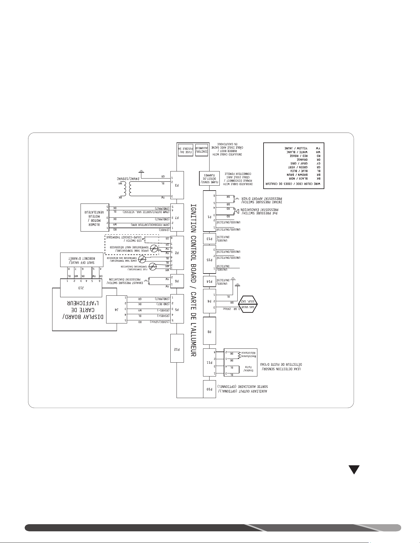
50
SCHÉMAS ÉLECTRIQUES
AX6078
!
AVERTISSEMENT
AVIS: NE PAS raccorder à un circuit muni d’un disjoncteur à détection de faute à la terre (DDFT). Afin d’éviter les risques
d’incendie, d’explosion ou d’asphyxie des occupants au monoxyde de carbone, ne faites JAMAIS fonctionner le chauffe-
eau s’il n’est pas correctement ventilé et s’il ne dispose pas d’un apport d’air adéquat assurant son bon fonctionnement.
Il est important que les sections de conduits s’emboîtent correctement aux raccords jusqu’à la cure complète de
l’adhésif. NE PAS percer de trous dans les conduits de plastique ou leurs raccords.
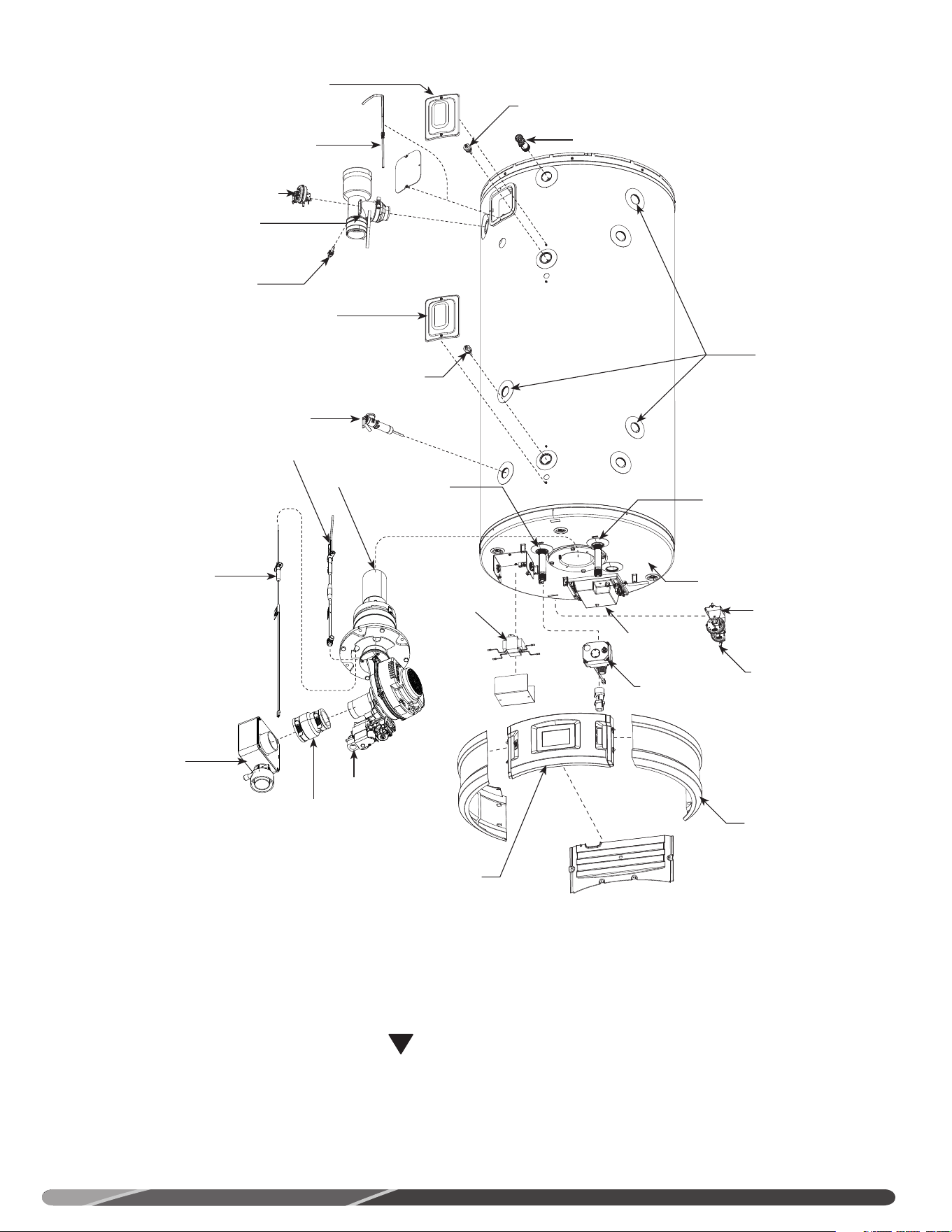
49
PIÈCES DE RECHANGE
Instructions pour la commande de pièces de rechange 75 USG
Veuillez fournir les renseignements suivants:
Les numéros de modèle et de série indiqués sur la
plaque signalétique.
Indiquez le type de gaz (gaz naturel ou propane),
comme indiqué sur la plaque signalétique.
La description et le numéro de la pièce (voir
ci-dessous).
ATTENTION
NE PAS tenter de corriger l’alimentation électrique ou
en gaz, de réparer la commande du gaz, les brûleurs,
les conduits de ventilation ou tout dispositif de sécurité.
Faites plutôt appel à un technicien d’entretien qualifié.
!
Commande
de l’allumage
Détecteur de flammes
Afficheur
Soupape du gaz
Ventilateur
Allumeur à étincelles
Brûleur
Réducteur de bruit
Panneau latéral
Transformateur
Clapet
anticonvection
sortie
Robinet de vidange
Drain de condensation
Thermistance inférieure
Capteur de température
Thermistance supérieure / coupe-circuit thermique (ECO)
Soupape de sûreté T&P
Clapet
anticonvection
entrée
Pressostat
apport d’air
Module de
l’anode
Pressostat
ventilateur
Robinet d’arrêt
automatique et
débitmètre
Pressostat évacuation
Couvercle du thermostat inférieur
Couvercle du thermostat supérieur
Détecteur de fuite
Connecteur en
caoutchouc
Anode
48
Codes
d’alarme (A)
et d’alerte (T)
Description Texte affiché à l’écran
T119 Inspection et entretien périodiques de l’appareil.
T119 Time to Clean Out the Condensate Drain Trap.
->Consulter le manuel d’utilisation et d’entretien pour les instructions.
Joindre Soutien technique ou réparateur au besoin.
T120 Inspection et entretien périodiques de l’appareil.
T120 Time to Replace the Neutralizer.
->Réinitialiser le code d’erreur en appuyant sur le bouton Clear.
Consulter le manuel d’utilisation et d’entretien ou joindre Soutien
technique.
A143
Signal du robinet d'arrêt erroné: les deux interrupteurs sont
simultanément OUVERTS ou FERMÉS.
A143 Shutoff Valve Inputs in Error.
-> Ouvrir manuellement le robinet, si aucune eau détectée ou si
l'appareil n'est pas en entretien. Joindre le soutien technique ou votre
fournisseur.
A200
Les versions logicielles du module de l'afficheur et du module
d'allumage sont incompatibles.
A200 Incompatible Ignition Control/Display Error.
-> Les modules d'allumage et d'affichage sont incompatibles entre
eux. Joindre le soutien technique.
T504
Erreur de synchronisation de communication puce WiFi. Ne signifie
pas que la puce est défaillante.
T504 Wifi Chip Communication Error.
-> Se reporter au manuel d'utilisation et d'entretien ou joindre le
soutien technique ou votre fournisseur.
AVANT D’APPELER UN RÉPARATEUR...
47
Codes
d’alarme (A)
et d’alerte (T)
Description Texte affiché à l’écran
T105
Vérifier si la sonde est installée dans le bac inférieur. Vérifier la
connexion P11, carte électronique de l’allumeur.
T105 Water Leak Sensor Not Installed
->Vérifier la connexion de la sonde. Consulter le manuel d’utilisation et
d’entretien ou joindre Soutien technique.
A108
Perte de communication entre carte de l’afficheur et carte de
l’allumeur. La carte de l’allumeur continue à fonctionner selon les plus
récents paramètres. Vérifier les connexions entre l’afficheur et P5 de la
carte de l’allumeur.
A108 Ignition Board Communication Failure
->Perte de communications avec la carte de l’allumeur. Si le problème
persiste, joindre le Soutien technique ou réparateur.
A110
Échec du test mensuel du robinet d’arrêt automatique (modèles
supérieurs seulement). La vanne ne s’est pas refermée dans le délai
prévu.
A110 Shutoff Valve Test Close Error
->Échec de fermeture du robinet d’arrêt automatique. Joindre Soutien
technique ou réparateur.
A111
Échec du test mensuel du robinet d’arrêt automatique (modèles
supérieurs seulement). La vanne ne s’est pas ouverte dans le délai
prévu. Désactive le chauffe-eau.
A111 Shutoff Valve Test Open Error
->Désactive le chauffe-eau. Ouvrir manuellement la vanne. Joindre
Soutien technique ou réparateur.
A112
Robinet d’arrêt automatique (modèles supérieurs seulement) est
fermée. Désactive le chauffe-eau.
A112 Shutoff Valve Not Open: Heating Disabled
->Ouvrir manuellement la vanne s’il ne semble pas y avoir une fuite
ou si l’appareil n’est pas en réparation. Joindre Soutien technique ou
réparateur.
T113
Intensité du courant de pointe du détecteur de flammes hors de la
plage moyenne. Dégradation de la sensibilité du détecteur de flammes
(saleté, suie). Nettoyer et inspecter.
T113 Flame Rod Degraded and Needs Servicing
->Nettoyer ou remplacer, selon manuel d’utilisation et d’entretien.
Joindre Soutien technique pour plus de détails.
T114
Intensité du courant de pointe du détecteur de flamme nettement hors
de la plage moyenne. Nettoyer et inspecter. Remplacer si nécessaire.
T114 Flame Rod Degraded and Needs Servicing
->Nettoyer ou remplacer, selon manuel d’utilisation et d’entretien.
Joindre Soutien technique pour plus de détails.
T115
Signaux de surveillance du système de combustion indiquent une
dégradation du rendement. Le système de combustion doit être
inspecté et entretenu.
T115 Combustion Health Degraded: Needs Service
->Dégradation du rendement du système de combustion. Joindre
Soutien technique ou réparateur.
T116
Signaux de surveillance du système de combustion indiquent une
importante dégradation du rendement. Le système de combustion doit
être inspecté et entretenu.
T116 Combustion Health Degraded. Needs Service
->Réinitialiser le code d’erreur en appuyant sur le bouton Clear.
Consulter le manuel d’utilisation et d’entretien ou joindre Soutien
technique.
T117 Inspection et entretien périodiques de l’appareil.
T117 Time to Drain and Inspect Tank
->Consulter le manuel d’utilisation et d’entretien pour les instructions,
ou joindre Soutien technique ou réparateur.
T118 Inspection et entretien périodiques de l’appareil.
T118 Time to Check Venting for Debris
->Consulter le manuel d’utilisation et d’entretien pour les instructions,
ou joindre Soutien technique ou réparateur.
AVANT D’APPELER UN RÉPARATEUR...
46
AVANT D’APPELER UN RÉPARATEUR...
Codes
d’alarme (A)
et d’alerte (T)
Description Texte affiché à l’écran
A038
Les contacts du relais #2 restent fermés. Permet à la soupape du gaz
de s’ouvrir à un moment inattendu. Désactive le chauffe-eau.
A038 Gas Relay 2 stuck closed. Call Tech Svc.
->Si le problème persiste, joindre le Soutien technique ou réparateur
A039
Défaillance carte électronique du détecteur de flammes; nécessite
remplacement si récurrent. Désactive le chauffe-eau.
A039 Flame sense cct fault. Call Tech Service.
->Si le problème persiste, joindre le Soutien technique ou réparateur
A040
Défaillance carte électronique (mémoire); nécessite remplacement si
récurrent. Désactive le chauffe-eau.
A040 Controller RAM fault. Call Tech Service.
->Si le problème persiste, joindre le Soutien technique ou réparateur
A041
Défaillance carte électronique (ROM); nécessite remplacement si
récurrent. Désactive le chauffe-eau.
A041 Controller ROM fault. Call Tech Service.
->Si le problème persiste, joindre le Soutien technique ou réparateur
A042
Défaillance carte électronique (EEPROM); nécessite remplacement si
récurrent. Désactive le chauffe-eau.
A042 Controller EEPROM fault. Call Tech Svc.
->Si le problème persiste, joindre le Soutien technique ou réparateur
A043
Défaillance carte électronique (prog. IC); nécessite remplacement si
récurrent. Désactive le chauffe-eau.
A043 IC Program execution fault. Call Tech Svc
->Si le problème persiste, joindre le Soutien technique ou réparateur
A044
Fréquence de l’alimentation électrique n’est pas à 60 Hz (hors des
limites admissibles). Désactive le chauffe-eau.
A044 Processor Clock/Line Frequency Disagree
->Si le problème persiste, joindre le Soutien technique ou réparateur
A101
Défaillance carte électronique (données de configuration); nécessite
remplacement si récurrent. Désactive le chauffe-eau.
A101 Configuration Data Restore Failure
->Échec d’initialisation du système de contrôle au démarrage. Joindre
Soutien technique ou réparateur.
A102 Réglez l’heure pour l’horloge interne.
A102 Time Clock needs to be programmed
->Paramètres, menu time/date, réglez l’heure et la date.
A103
Défaillance carte électronique de l’afficheur; nécessite remplacement
si récurrent. Désactive le chauffe-eau.
A103 Time Clock not advancing time properly
->Joindre un réparateur qualifié.
A104
Présence d’eau détectée par la sonde du bac inférieur. Trouver la
source et faire cesser la fuite. Selon les paramètres actifs, peut
désactiver le chauffe-eau.
A104 Water Leak Detected
->Eau détectée par la sonde/carte électronique. ->Joindre un
réparateur qualifié.
45
AVANT D’APPELER UN RÉPARATEUR...
Codes
d’alarme (A)
et d’alerte (T)
Description Texte affiché à l’écran
A025 Aucune rotation du ventilateur détectée. Désactive le chauffe-eau.
A025 No Blower RPM feedback. Call Tech Service .
->Joindre Soutien technique ou réparateur.
A026 Vitesse de rotation détectée ≥ 300 RPM de la valeur-cible > 1 minute.
A026 Blower expected RPM vs actual RPM mismatch.
->Joindre Soutien technique ou réparateur.
A027
Signal de détection de flammes avant l’ouverture de la soupape de
gaz. Désactive le chauffe-eau.
A027 Flame present before ignit. Call Tech Svc.
->Réinitialiser le code d’erreur en mettant l’appareil à l’arrêt, puis en
le remettant en marche. Si le problème persiste, joindre le Soutien
technique ou réparateur
A028
Signal de détection de flammes 10 secondes après la fermeture de la
soupape de gaz. Désactive le chauffe-eau.
A028 Flame present w/o heating. Call Tech Svc.
->Réinitialiser le code d’erreur en mettant l’appareil à l’arrêt, puis en
le remettant en marche. Si le problème persiste, joindre le Soutien
technique ou réparateur
T029 Le chauffe-eau n’allume pas. T029 Failed ignition. Retrying.
A030 Perte du signal de flammes. A030 Flame lost during heating. Retrying.
T032 Thermistance inférieure (entrée): erreur de conversion A/D.
T032 Lower Tank temp A/D error. Call Tech Svc.
->Si le problème persiste, joindre le Soutien technique ou réparateur
A033
Thermistance conduit d’évacuation: erreur de conversion A/D.
Désactive le chauffe-eau.
A033 Flue sensor A/D error. Call Tech Service.
->Si le problème persiste, joindre le Soutien technique ou réparateur
A034
Thermistance supérieure (sortie): erreur de conversion A/D. Désactive
le chauffe-eau.
A034 Upper Tank temp A/D error. Call Tech Svc.
->Si le problème persiste, joindre le Soutien technique ou réparateur
A035
Non-fermeture des contacts du relais #1 de la commande du gaz.
L’appareil reprend de nouveaux cycles d’allumage.
T035 Gas Relay 1 stuck open. Call Tech Service
->Si le problème persiste, joindre le Soutien technique ou réparateur
A036
Les contacts du relais #1 restent fermés. Permet à la soupape du gaz
de s’ouvrir à un moment inattendu. Désactive le chauffe-eau.
A036 Gas Relay 1 stuck closed. Call Tech Svc.
->Si le problème persiste, joindre le Soutien technique ou réparateur
A037
Non-fermeture des contacts du relais #2 de la commande du gaz.
Peut entraîner un cyclage répétitif et l’accumulation de gaz dans la
chambre de combustion. Désactive le chauffe-eau.
A037 Gas Relay 2 stuck open. Call Tech Service
->Si le problème persiste, joindre le Soutien technique ou réparateur.
44
AVANT D’APPELER UN RÉPARATEUR...
Codes
d’alarme (A)
et d’alerte (T)
Description Texte affiché à l’écran
A012 Flamme détectée en mode Attente/Désactivé
A012
Réinitialiser le code d’erreur en mettant l’appareil à l’arrêt, puis en
le remettant en marche. Si le problème persiste, joindre le Soutien
technique ou réparateur
A016
Circuit du coupe-circuit thermique (ECO) est ouvert. Désactive le
chauffe-eau.
A016 High Tank Temperature. Call Tech Service.
->Réinitialiser le code d’erreur en appuyant sur le bouton Clear.
Consulter le manuel d’utilisation et d’entretien ou joindre Soutien
technique.
A017
Température des gaz de combustion supérieure à 155°C (68°C).
Désactive le chauffe-eau.
A017 High Flue Temp. Recycle unit ON/OFF.
->Le ventilateur continue à tourner jusqu’à ce que descende la
température dans le conduit d’évacuation. Si le problème persiste,
joindre le Soutien technique ou réparateur.
A018
Circuit du capteur de température (thermistance) de l’évacuation est
ouvert. Désactive le chauffe-eau.
A018 Flue Temp Sensor open. Check wiring.
->Vérifier les fils du capteur. Si le problème persiste, se rapporter au
manuel d’utilisation et d’entretien ou joindre le Soutien technique.
A019
Circuit du capteur de température (thermistance) de l’évacuation est
en court-circuit. Désactive le chauffe-eau.
A019 Flue Temp Sensor shorted. Call Tech Svc.
->Vérifier les fils du capteur. Si le problème persiste, se rapporter au
manuel d’utilisation et d’entretien ou joindre le Soutien technique.
T020
Circuit du capteur de température (thermistance) du raccord inférieur
est ouvert.
T020 Lower Tank Sensor open. Check wiring.
->Vérifier les fils du capteur. Si le problème persiste, se rapporter au
manuel d’utilisation et d’entretien ou joindre le Soutien technique.
T021
Circuit du capteur de température (thermistance) du raccord inférieur
est en court-circuit.
T021 Lower Tank Sensor shorted. Call Tech Svc.
->Vérifier les fils du capteur. Si le problème persiste, se rapporter au
manuel d’utilisation et d’entretien ou joindre le Soutien technique.
A022
Circuit du capteur de température (thermistance) du raccord supérieur
est ouvert. Désactive le chauffe-eau.
A022 Upper Tank Sensor open. Check wiring.
->Vérifier les fils du capteur. Si le problème persiste, se rapporter au
manuel d’utilisation et d’entretien ou joindre le Soutien technique.
A023
Température dans la partie supérieure du réservoir est supérieure à
96°C (205°F). Désactive le chauffe-eau.
A023 Upper Tank temp. too hot. Call Tech Svc.
->Réinitialiser le code d’erreur en appuyant sur le bouton Clear.
Consulter le manuel d’utilisation et d’entretien ou joindre Soutien
technique.
A024
Circuit du capteur de température (thermistance) du raccord supérieur
est en court-circuit. Désactive le chauffe-eau.
A024 Upper Tank sensor shorted. Call Tech Svc.
->Vérifier les fils du capteur. Si le problème persiste, se rapporter au
manuel d’utilisation et d’entretien ou joindre le Soutien technique.
43
Codes
d’alarme (A)
et d’alerte (T)
Description Texte affiché à l’écran
A001
Verrouillage de l’allumage à la suite de 9 échecs consécutifs
d’allumage. Désactive le chauffe-eau.
A001 Ignition lockout.
->Réinitialiser le code d’erreur en mettant l’appareil à l’arrêt, puis en
le remettant en marche. Si le problème persiste, joindre le Soutien
technique ou réparateur.
A002
Verrouillage, instabilité des flammes. Trois pertes du signal de flammes
lors d’un même cycle de chauffe. Désactive le chauffe-eau.
A002 Flame is not stable.
->Réinitialiser le code d’erreur en mettant l’appareil à l’arrêt, puis en
le remettant en marche. Si le problème persiste, joindre le Soutien
technique ou réparateur.
A003
Le circuit du pressostat s’est ouvert pendant que le ventilateur
fonctionnait. Désactive le chauffe-eau.
A003 Intake Switch open. Check Wiring/Venting
->Vérifier les fils du pressostat et les conduits de ventilation. Si le
problème persiste, joindre le Soutien technique ou réparateur.
A004
Le circuit du pressostat s’est ouvert pendant un cycle de chauffage.
Désactive le chauffe-eau.
A004 PoF Switch error H. Check Blower/Wiring.
->Vérifier les fils du pressostat et les conduits de ventilation. Si le
problème persiste, joindre le Soutien technique ou réparateur.
A005
Le circuit du pressostat s’est ouvert pendant un cycle de pré-purge.
Désactive le chauffe-eau.
A005 PoF Switch error E. Check Blower/Wiring.
->Vérifier les fils du pressostat et les conduits de ventilation. Si le
problème persiste, joindre le Soutien technique ou réparateur.
A006 Le circuit du pressostat s’est ouvert pendant un cycle de post-purge.
A006 PoF Switch error P. Check Blower/Wiring.
->Vérifier les fils du pressostat et les conduits de ventilation. Si le
problème persiste, joindre le Soutien technique ou réparateur.
A007
Le circuit du pressostat d’évacuation s’est ouvert pendant un cycle de
chauffe. Désactive le chauffe-eau.
A007 Exhaust Switch open. Check Wiring/Venting
->Vérifier les fils du pressostat et les conduits de ventilation. Si le
problème persiste, joindre le Soutien technique ou réparateur.
A008
Le circuit du pressostat est fermé avant la mise en marche du
ventilateur. Désactive le chauffe-eau.
A008 PoF Switch/Blower mismatch. Call Tech Svc
->Le circuit du pressostat est fermé alors que le ventilateur est
désactivé. Joindre Soutien technique ou réparateur.
AVANT D’APPELER UN RÉPARATEUR...
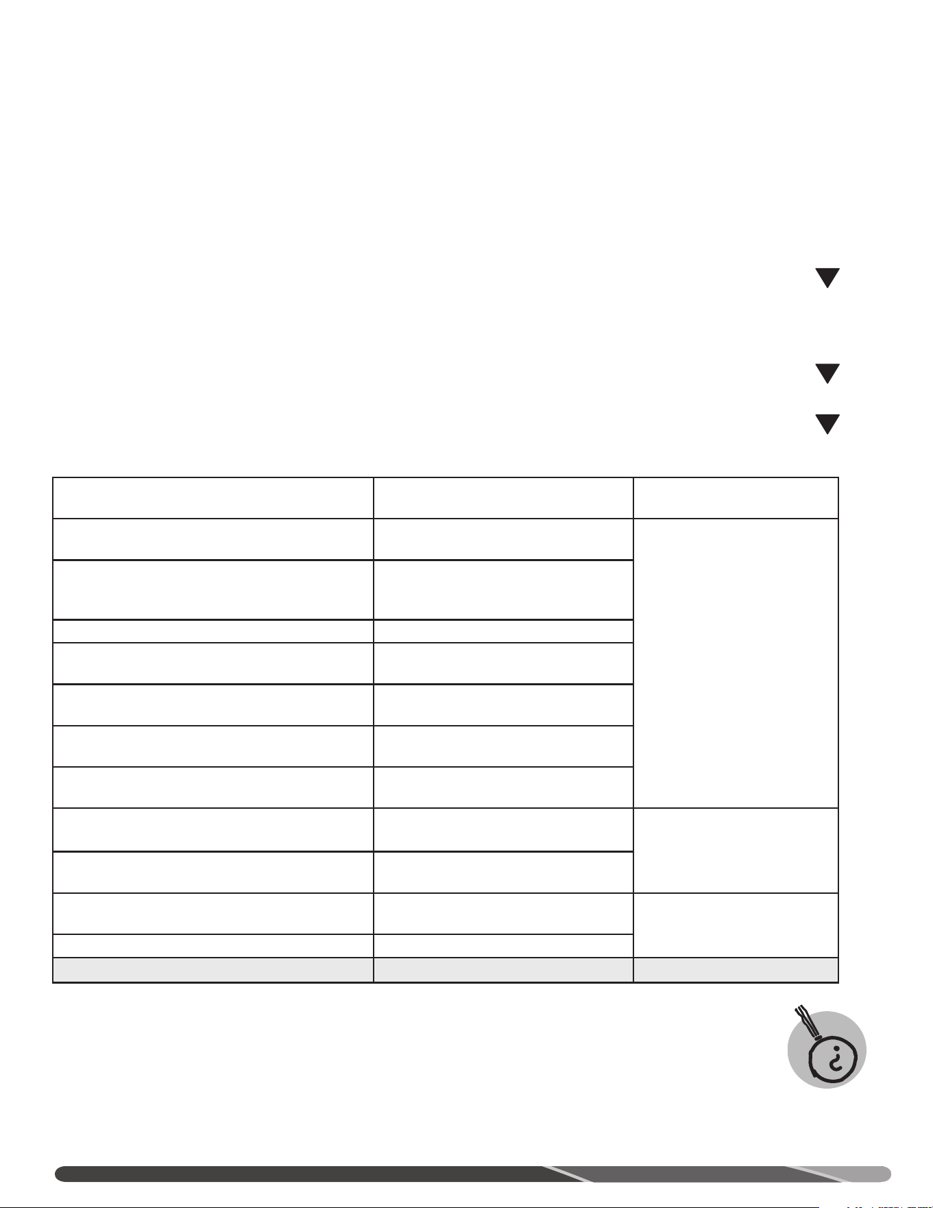
42
AVANT D’APPELER UN RÉPARATEUR...
Guide de dépannage
Économisez temps et argent! Consultez ce Guide de dépannage avant tout, il pourrait vous éviter d’avoir à appeler un
réparateur.
Problème Cause possible À faire
Le brûleur ne
s’allume pas
Problème avec la commande du gaz. Appelez un technicien d’entretien qualifié.
Mauvaise mise à la masse de l’appareil ou
mise à la terre du circuit d’alimentation.
S’assurer que l’appareil et le circuit sont
correctement mis à la masse/terre.
Le brûleur ne reste pas allumé
Les flammes n’entrent pas en contact
avec le détecteur de flammes.
Appeler un technicien d’entretien qualifié.
Mauvaise mise à la masse de l’appareil ou
mise à la terre du circuit d’alimentation.
S’assurer que l’appareil et le circuit sont
correctement mis à la masse/terre.
Pas assez d’eau chaude ou pas
d’eau chaude.
La consommation d’eau chaude dépasse
la capacité du chauffe-eau.
Attendre que le chauffe-eau génère plus d’eau
chaude à la suite d’une grande demande.
Faible pression de gaz
Mesurer la pression d’admission en gaz du chauffe-
eau.
Réglage du point de consigne trop bas
Consulter la section "Interface-utilisateur" de ce
manuel pour savoir comment régler la température.
Robinets d’eau chaude ouverts ou fuites
S’assurer que les tous les robinets d’eau chaude
sont fermés.
Interrupteur “ON/OFF” désactivé S’assurer que l’interrupteur est à la position "ON".
La température de l’eau froide est plus
basse qu’à l’habitude.
Il se pourrait que la température de l’eau froide
s’abaisse en hiver. Attendre que le chauffe-eau
chauffe le contenu du réservoir.
Le brûleur ne reste pas allumé
Lire la section "Brûleur principal" du présent
manuel.
L’eau est trop chaude. Réglage du point de consigne trop élevé
Consulter la section "Interface-utilisateur" de ce
manuel pour savoir comment régler la température.
ATTENTION:
Assurez-vous de couper l’alimentation électrique du chauffe-eau avant de retirer le couvercle, POUR TOUTE RAISON.
ATTENTION:
Étiquetez tous les fils avant de les déconnecter lors d’un entretien. Des erreurs de raccordement peuvent entraîner un
fonctionnement erratique ou dangereux. ASSUREZ-VOUS DU BON FONCTIONNEMENT DU CHAUFFE-EAU À LA SUITE DE TOUT
ENTRETIEN!
ATTENTION:
NE PAS tenter de corriger l’alimentation électrique ou en gaz, de réparer la commande du gaz, les brûleurs, les conduits de
ventilation ou tout dispositif de sécurité. Faites plutôt appel à un technicien d’entretien qualifié.
NOTE: Notre Service technique peut vous envoyer un manuel de formation contenant des informations de dépannage et de réparation
plus avancées.
!
!
!
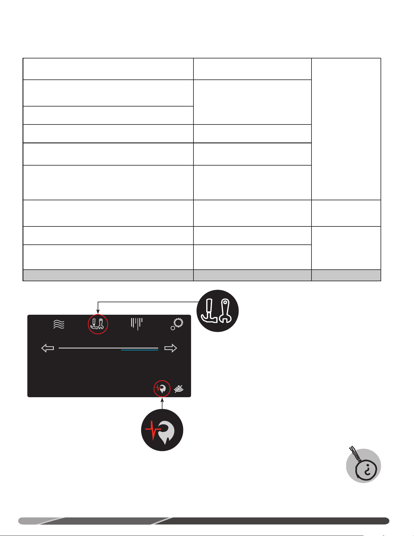
41
Guide de dépannage
Économisez temps et argent! Consultez ce Guide de dépannage avant tout, il pourrait vous éviter d’avoir à appeler un
réparateur.
Problème Causes probables À faire
Écran éteint
Appareil non alimenté en électricité
Vérifier le disjoncteur de l’appareil, le bouton marche/arrêt et le
fusible de la carte électronique de l’allumeur.
Harnais de câbles de la carte est
déconnecté
S’assurer que le harnais de câbles de la carte électronique est
connecté.
Le ventilateur ne
fonctionne pas
Le moteur ddu ventilateur n’est pas
alimenté en électricité
S’assurer que la carte électronique et tous les câbles du
ventilateur sont connectés et alimentés en électricité. S’assurer
que les câbles ou leurs connecteurs sont en bon état.
Le brûleur ne
s’allume pas
Air dans les conduites du gaz Laisser l’appareil effectuer au moins 3 cycles d’allumage, afin
de purger l’air des conduites de gaz. Si l’appareil n’effectue pas
de cycle d’allumage, appelez un technicien d’entretien qualifié
pour qu’il purge les conduites du gaz.
Robinet d’arrêt manuel
du gaz refermé.
S’assurer que le robinet d’arrêt manuel du gaz de l’appareil est
bel et bien ouvert.
Conduit d’apport d’air ou d’évacuation
bloqué
Appeler un technicien d’entretien qualifié pour qu’il évalue la
sévérité du blocage.
Pressostat
S’assurer que les tubes du pressostat ne sont pas tordus ou
déconnectés.
Un blocage du conduit d’apport d’air ou d’évacuation empêche
le pressostat de fermer le circuit et le chauffe-eau de
fonctionner. Appeler un technicien d’entretien qualifié.
Mauvaises connexions électriques Appeler un technicien d’entretien qualifié.
Status: Standby
StatusSettings
warm hot very hot
Disable
120°
Service
Si l’un des indicateurs de santé ou si l’icône d’entretien de
l’écran d’accueil clignote, cela signale que votre chauffe-eau
nécessite une intervention. Appuyez sur l’icône d’entretien
pour visualiser les pages des alarmes et alertes en cours, de
l’historique des alarmes et de l’état de santé. Appuyez sur l’icône
de l’état de santé pour atteindre la page de l’état de santé.
Status: Standby
StatusSettings
warm hot very hot
Disable
120°
Service
Status: Standby
StatusSettings
warm hot very hot
Disable
120°
Service
AVANT D’APPELER UN RÉPARATEUR...
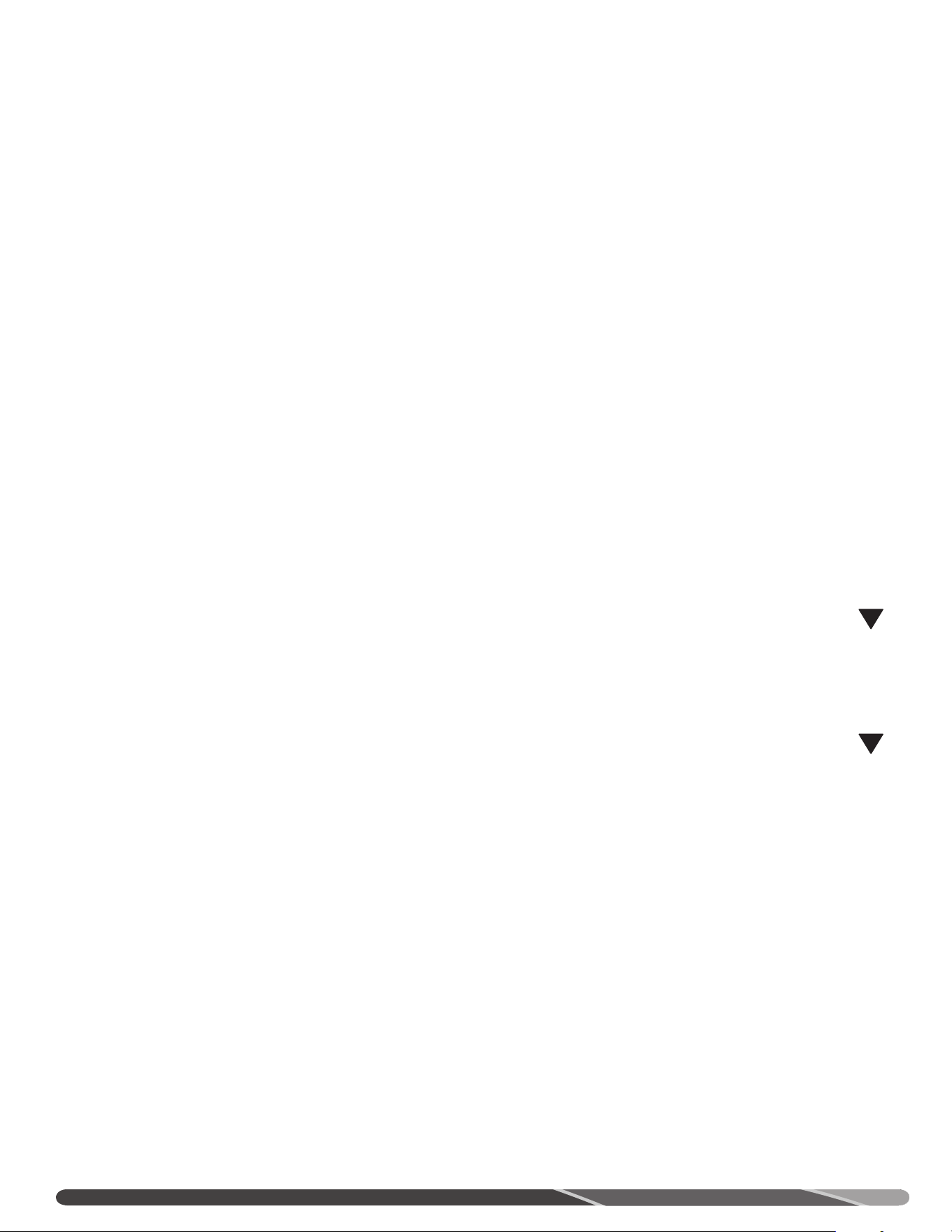
40
Lorsque bien entretenu, votre chauffe-eau vous procurera une
fiabilité sans pareille des années durant. Nous
suggérons fortement que le propriétaire du chauffe-eau mette
en place et applique un programme d’entretien régulier. Il est
aussi suggéré qu’un technicien d’entretien qualifié effectue une
inspection périodique de la soupape de sûreté et du système de
ventilation.
1. ENTRETIEN PRÉVENTIF PÉRIODIQUE
PRESSOSTAT — Inspectez le pressostat du
conduit d’apport d’air et assurez-vous de l’absence
de débris ou de blocages. Nettoyez régulièrement le conduit afin
de
prévenir toute accumulation de débris.
B. COLLECTEUR DE CONDENSATION — Assurez-vous de
l’absence de blocage.
C. CONNEXIONS ÉLECTRIQUES — Inspectez régulièrement tous
les raccordements électriques et l’état du filage.
ATTENTION:
Étiquetez tous les fils avant de les déconnecter lors d’un
entretien.
Des erreurs de raccordement peuvent entraîner
un fonctionnement erratique ou dangereux.
ATTENTION:
ASSUREZ-VOUS DU BON FONCTIONNEMENT DU CHAUFFE-EAU
APRÈS TOUT ENTRETIEN!
Coupez l’alimentation électrique du chauffe-eau (“OFF”) avant
d’effectuer toute inspection ou tout entretien.
Avant de manuellement déclencher la soupape de sûreté,
assurez-vous qu’aucune personne ne sera exposée au jet
d’eau chaude expulsé par celle-ci. L’eau ainsi vidangée
risque d’être suffisamment chaude pour présenter un risque
d’ÉBOUILLANTAGE. L’eau doit être dirigée vers un drain de
capacité suffisante afin d’éviter toute blessure ou tout dommage.
AVIS: une décharge occasionnelle par la soupape de
sûreté température et pression est parfois le résultat
d’un phénomène d’expansion thermique dans un système
d’alimentation "fermé". Communiquez avec votre fournisseur
d’eau ou un inspecteur en plomberie pour vous informer sur
les méthodes de contrôle de la pression. NE PAS boucher
l’orifice de la soupape de sûreté.
E. RÉSERVOIR — Une routine d’entretien périodique doit inclure
le nettoyage des dépôts du réservoir. Sauf si la source d’eau
est très douce (dureté de 0 à 5 grains), de dépôts de calcaire
et de tartre s’accumulent inévitablement dans le réservoir.
De plus, le rythme d’accumulation de dépôts calcaires varie
en fonction de la température de l’eau. Ces accumulations
calcaires peuvent réduire l’efficacité du chauffe-eau et réduire
sa durée de vie.
Il est suggéré de drainer chaque mois quelques litres du réservoir
afin d’évacuer ces dépôts.
F. MISE HORS-SERVICE SAISONNIÈRE — S’il est prévu que le
chauffe-eau demeurera inutilisé pendant une longue période
de temps (60 jours ou plus), il devrait être mis à l’arrêt. Le
chauffe-eau et ses conduites d’eau devraient être drainés s’il
y a possibilité d’une exposition au gel. Il est recommandé de
faire vérifier les composantes et le bon fonctionnement du
chauffe-eau par un technicien d’entretien qualifié avant sa
remise en service. AVIS: Se reporter à la note d’avertissement
relative à l’hydrogène gazeux dans la section «Précautions de
sécurité» du présent manuel. Il est suggéré de drainer chaque
mois quelques litres du réservoir afin d’évacuer ces dépôts.
G. SYSTÈME DE VENTILATION — Inspectez le système de
ventilation au moins annuellement afin de vous assurer que
ses conduits sont libres de toute obstruction et que le tuyau de
raccordement entre le ventilateur du chauffe-eau et le conduit
de ventilation soit bien positionné et solidement fixé. Le cas
échéant, nettoyez toute obstruction du tuyau de raccordement
ou de la terminaison.
ENTRETIEN
!
!
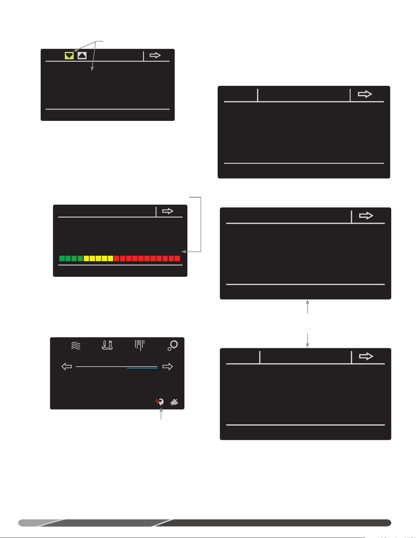
39
ALARMES ACTIVES (CURRENT ALARMS): la page des alarmes
actives affiche les irrégularités détectées par le contrôleur du
chauffe-eau. Appuyez sur “more info” pour afficher plus de
détails sur le problème courant. La page “alarm history” affiche
la liste des précédentes alarmes.
HISTORIQUE DES ALARMES (ALARM HISTORY): affiche la liste
des alarmes précédentes.
SANTÉ DU SYSTÈME (SYSTEM HEALTH): affiche la santé du
système de combustion et du système en général. Ces systèmes
peuvent avoir l’un des 3 niveaux de santé suivants:
ALERTES D’ENTRETIEN (SERVICE ALERTS): la page “service
alerts” permet de configurer la méthode et la fréquence de
communication des alertes de nettoyage du collecteur de
condensation, de remplacement du neutralisant, ainsi que de
vidange et d’inspection du réservoir.
ALERTES D’ENTRETIEN (SERVICE ALERTS): la page “service
alerts” permet de configurer la méthode et la fréquence de
communication des alertes de nettoyage du collecteur de
condensation, de remplacement du neutralisant, ainsi que de
vidange et d’inspection du réservoir.
current alarms
A007 Exhaust Switch open. Check Wiring/Venting
more
info
clear
service alerts
Drain & Inspect Tank:
Check Venting:
Clean Drain Trap:
Replace Neutralizer:
Enabled
Enabled
Enabled
Enabled
9 months
6 months
1500 hours
1500 hours
9.0 left
6.0 left
1500 left
1500 left
Sélectionnez “more info” pour
obtenir une description plus
détaillée de l’alarme courante.
Écran d’affichage de la santé du système de combustion et de la
santé générale. Depuis l’écran d’accueil, appuyez sur l’icône de l’état
de santé.
Cette icône s’affiche sur l’écran d’accueil
lorsque l’état du système de combustion
est critique. Appuyez sur cette icône pour
afficher l’écran de santé du système.
Sélectionnez cette option, puis appuyez sur
la flèche vers le haut ou vers le bas pour
sélectionner les préférences d’avertissement
d’entretien.
Trouble-Shooting
A007 Exhaust Switch open. Check Wiring/Venting
Check switch wiring and venting. If problem
persist, please contact technical support or
service provider.
alarm history
14:48:13 01/11/17 A007 Echaust Switch open. Check wiring/venting
clear
SANTÉ COMBUSTION:
1. Fonctionnement normal - aucune action requise.
2. Planifier entretien ou remplacement.
3. Besoin d’entretien - joindre réparateur,
system health
(typical 10K cyc/yr)
(typical 2K hrs/yr)
Combustion Health Status: Operating Normally
Lifetime Heating Cycles:
Lifetime Run Time Hours:
1
0.0
baseline init
Status: Standby
StatusSettings
warm hot very hot
Disable
120°
Service
INTERFACE-UTILISATEUR
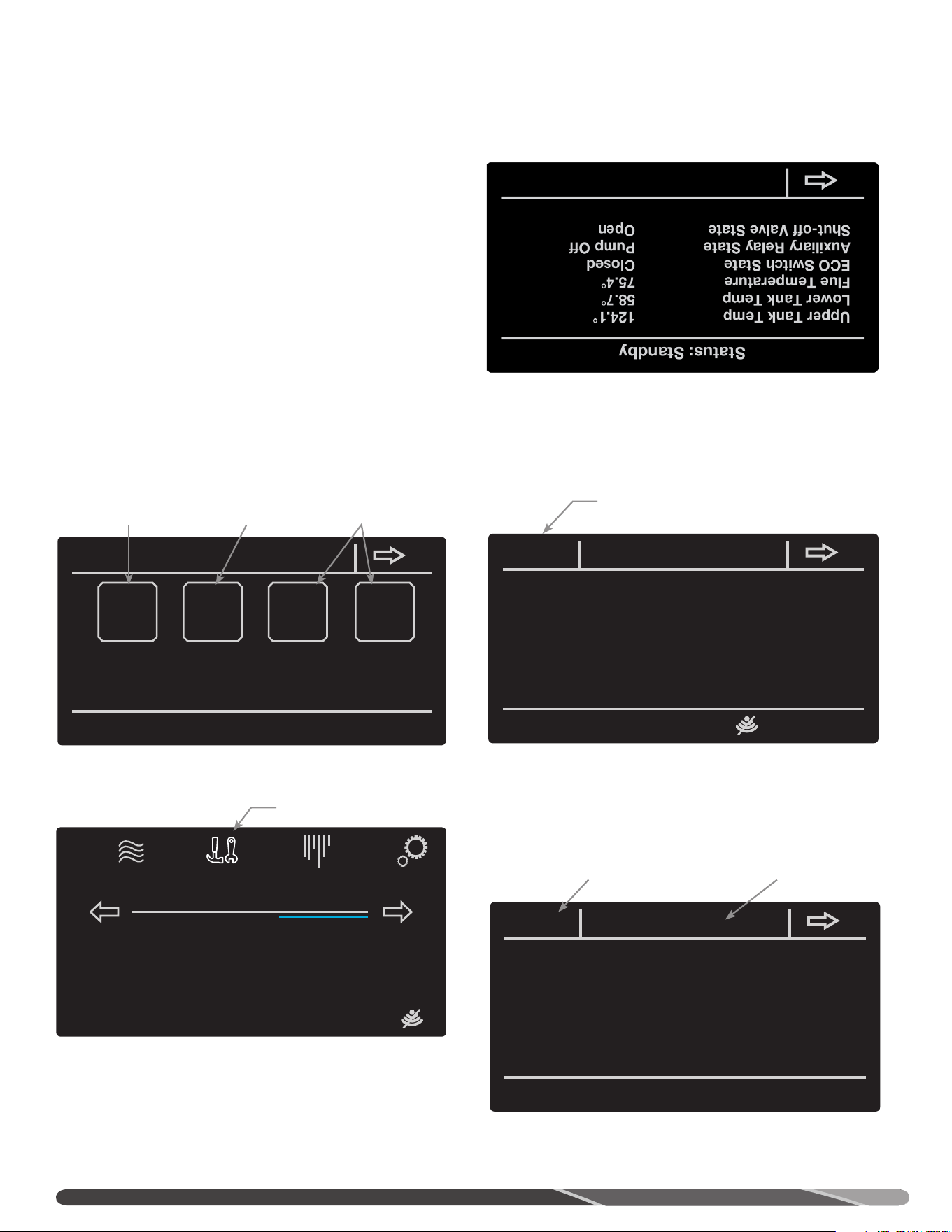
38
service
Product Model Number:
Product Serial Number:
Software Version Number: WH-DRG1-00-00-86
current
alarms
alarm
history
system
health
service
alerts
STATUT WI-FI (WI-FI STATUS): appuyez sur ‘wifi status’ pour
atteindre la page de statut et de paramétrage de l’interface Wi-Fi
du chauffe-eau.
AUTRES FONCTIONS (MORE): appuyez sur ‘more’ pour afficher
la température au haut et au bas du réservoir, ainsi que dans le
conduit d’évacuation, l’état du coupe-circuit thermique (ECO) et
du relais auxiliaire.
MENU ENTRETIEN (SERVICE)
L’écran d’entretien une série de renseignements sur l’appareil:
description, alarmes, santé du système et alertes d’entretien.
Pour plus de détails sur les codes d’alarmes, consultez la section
"Avant d’appeler un réparateur" du présent manuel.
S’il y a une alarme active, le bouton “Service” de l’écran d’accueil
clignote. Il suffit d’appuyer sur le bouton “Service” pour afficher
les alarmes actives ainsi que l’historique des alarmes.
Appuyez sur “Service” pour
afficher les pages d’alarmes,
d’alertes et de santé du système.
Sélectionnez “wifi status” pour
connaître l’état de l’interface Wi-Fi
et la configurer.
Appuyez sur “more” pour afficher
les températures du système,
ainsi que les statuts du coupe-
circuit thermique et du relais
auxiliaire.
Sélectionnez “wifi setup” pour connecter votre
chauffe-eau à votre réseau sans fil.
Les pages “current
alarms” et “alarm history”
vous permettent de voir
les alarmes actives et
l’historique des alarmes.
La page “system
health” affiche la
santé du système
de combustion
et du système en
général.
La page “service alerts”
permet de configurer la
méthode et la fréquence
de communication des
alertes de ventilation de
nettoyage du collecteur
de condensation, de
remplacement du
neutralisant, ainsi que de
vidange et d’inspection du
réservoir.
Status: Standby
StatusSettings
warm hot very hot
Disable
120°
Service
Status: Water Heater Disabled
Air Intake Press. Switch
Exhaust Press. Switch
Current Fan Speed
Flame Current
Closed
Closed
0RPM
0.0 uA
morewifi status
wifi status
WiFi Device Status............
WiFi Signal Strength [dBm]....
Econer wifi SW Version........
WiFi Module SW Version........
MAC Address...................
SSID..........................
IP Address ...................
Subnet Mask...................
Gateway.......................
Ready To Connect
0
RH-WIFI-02-01-05
14.76.36.P103
F0-03-8C-B3-C6-CC
wifi setup
INTERFACE-UTILISATEUR
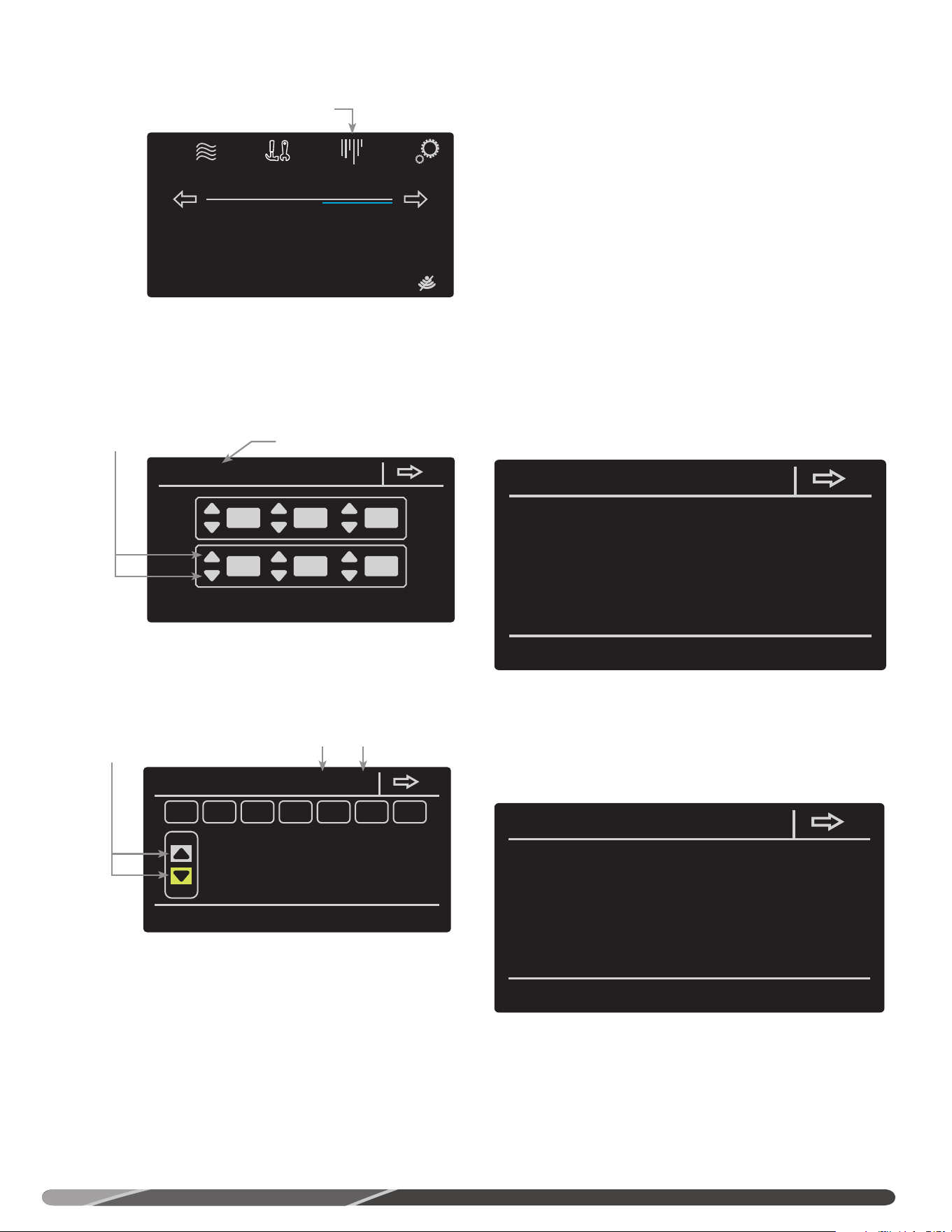
37
PARAMÈTRES DE BASE: Sélection de l’unité de température,
verrouillage/déverrouillage de l’écran, activation/désactivation
du signal sonore d’alarme et configuration de l’interface EcoNet.
Il suffit d’appuyer sur les flèches haut/bas pour modifier les
réglages. Cet écran donne aussi accès à la configuration Wi-Fi.
PARAMÈTRES DE CONFIGURATION: Sélection du mode de
chauffage, réglage de la pompe de recirculation, entrée/sortie
auxiliaire, activation/désactivation de la modulation de puissance,
configuration de l’alarme de détection de fuite.
Pour modifier ce paramètre, il suffit de le toucher et d’appuyer sur
les flèches haut/bas pour modifier la sélection.
Configuration de la pompe de recirculation:
Off - Lorsque la pompe de recirculation n’est pas utilisée ou
installée.
On - Pour manuellement activer la pompe. Fonction utile pour
tester l’installation. Non recommandé en fonctionnement normal.
Horaire - La pompe de recirculation fonctionne sur un cycle
"marche/15 min, arrêt 15 min" quand le chauffe-eau est au mode
«Home» (voir RÉGLAGES DE L’HORAIRE). Quand le chauffe-eau est
en mode «Away», la pompe de recirculation ne fonctionne pas.
À la demande - La pompe de recirculation peut être configurée
pour être activée à partir de l’application mobile. Lorsqu’elle est
ainsi activée, la pompe fonctionne pendant 15 minutes.
Ce chauffe-eau possède une option de modulation de la puissance.
Il est possible de la désactiver en sélectionnant ‘No’ pour l’option
‘Modulation Disabled’ à l’aide des flèches.
HORAIRE (SCHEDULE SETTINGS): permet de définir l’horaire
d’activation et de désactivation du chauffe-eau. Vous pouvez
définir l’horaire de fonctionnement (jours et heures) de votre
chauffe-eau. Pour accélérer cette procédure, vous pouvez copier/
coller l’horaire d’un jour à l’autre.
HEURE ET DATE (TIME/DATE SETTINGS): pour régler la date et
l’heure du système. Si applicable, sélectionnez l’option d’heure
avancée (D.S.T.).
MENU STATUT (STATUS)
L’écran Statut “Status” procure des renseignements sur le mode
de fonctionnement actuel, les codes diagnostiques et l’état des
détecteurs. Il indique aussi le statut de l’interface Wi-Fi.
basic settings
Temperature Display
Screen Adjustment Lock?
Beep On Alarm
EcoNet Network Instance
Elevation
Fahrenheit
No
Enabled
1
Normal
config settings
Shutoff Valve Config
Heating Mode
Recirc. Pump Config
Aux Output Select
When Leak Detected
Not Installed
Normal
On
Recirc. Pump
Alarm Only
schedule settings
Wed. Jan.11, 2:49 pm
Morning:
Night:
Mon.
08:00 am
06:00 pm
Time
Occupied
Occupied
Schedule
Tue.
copy
day
paste
day
cancel
Wed. Thu. Fri. Sat. Sun.
set to time and date
accept
D.S.T.
enabled
:
10 54 am
:
Jan. 11 2017
Les flèches haut/bas servent
au réglage de l’heure et de
l’horaire de fonctionnement.
Utilisez les fonctions Copy pour
copier les paramètres de la journée
sélectionnée dans une autre journée.
Les flèches haut/bas
servent au réglage de
l’heure, du jour, du mois et
de l’année.
La fonction DST (heure avancée)
permet de tenir compte des
changements d’heures saisonniers.
INTERFACE-UTILISATEUR
Il suffit d’appuyer sur le bouton “Status”
pour afficher le statut d’une série de
fonctions du chauffe-eau.
Status: Standby
StatusSettings
warm hot very hot
Disable
120°
Service
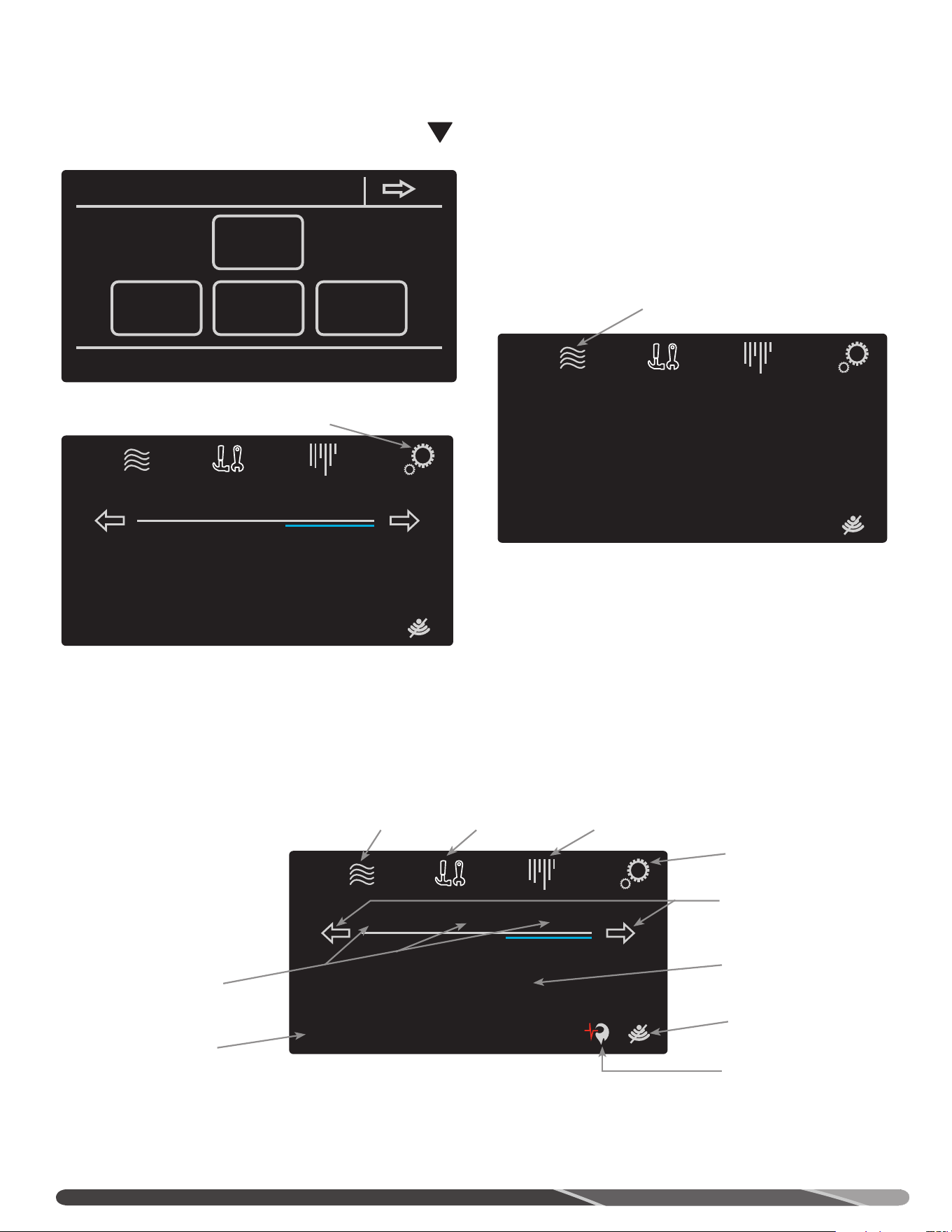
36
UTILISATION DE L’ÉCRAN PRINCIPAL
Status: Standby
StatusSettings
warm hot very hot
Disable
120°
Service
État de fonctionnement
Bouton
Paramètres
Bouton Statu
Bouton
Entretien
Bouton
Marche/Arrêt
Réglage rapide de
la température
Indicateur et
paramètres
Wi-Fi
Icônes de statut
Molette de
de consigne
Molette de
réglage
INTERFACE-UTILISATEUR
MISE EN SERVICE
Une fois le chauffe-eau alimenté en électricité, appuyez sur le
bouton de mise en marche; l’assistant de démarrage de l’afficheur
ACL suggérera la configuration des paramètres suivants:
1. Configuration de l’heure et de la date
2. Configuration des heures d’ouverture du commerce
3. Configuration Wi-Fi
Suivez les instructions affichées à l’écran pour effectuer ces
configurations. Certains des paramétrages peuvent être remis à
plus tard.
MISE EN MARCHE DE L’APPAREIL
RÉGLAGE DE LA TEMPÉRATURE
La température de l’eau du réservoir se maintient à la température
de consigne indiquée sur l’écran d’accueil. Pour modifier la
température de consigne, appuyez sur la flèche appropriée à
l’écran pour sélectionner la valeur désirée.
Vous pouvez aussi sélectionner l’un des 3 paramètres
préprogrammés, dont la température correspond aux valeurs
suivantes:
Tiède: 43°C (110°F)
Chaude: 49°C (120°F)
Très chaude: 71°C (160°F)
Il suffit d’appuyer sur ‘warm’, ‘hot’, ou ‘very hot’ pour sélectionner
la température de consigne correspondante.
MENU PARAMÈTRES (SETTINGS)
Le menu Paramètres donne accès aux paramètres et
configurations de base, aux horaires de fonctionnement et aux
réglages de l’heure/date
Status: Water Heater Disabled
Water Heater Disabled
StatusSettings Enable
Service
Appuyez sur le bouton Enable pour
mettre le chauffe-eau en marche.
Pour commencer, appuyez sur l’icône
Paramètres.
Status: Standby
StatusSettings
warm hot very hot
Disable
120°
Service
settings
wifi setup
time/date
basic configs schedule
DANGER:
La sélection d’une température plus élevée augmente les
risques D’ÉBOUILLANTAGE.
!
35
A. Fermez le robinet d’arrêt manuel du gaz du chauffe-eau si
celui-ci a surchauffé, s’il a été exposé à un incendie ou à
une inondation, s’il est endommagé ou si la commande du
gaz ne coupe pas l’alimentation en gaz.
B. NE PAS mettre le chauffe-eau sous tension si son réservoir
n’est pas complètement rempli d’eau.
C. NE PAS mettre pas le chauffe-eau sous tension si le robinet
d’arrêt de la canalisation d’alimentation en eau froide du
chauffe-eau est fermée.
D. NE PAS ranger ni utiliser de l’essence ou d’autres liquides
ou vapeurs inflammables (ex.: adhésifs, diluant) à proximité
de cet appareil ou de tout autre appareil. Si ces produits
doivent être utilisés à proximité, ouvrez les portes et fenêtres
pour ventiler la pièce et fermez tous les appareils au gaz, y
compris leur veilleuse, afin d’éviter l’allumage des vapeurs
inflammables.
AVIS: des vapeurs inflammables peuvent être transportées
d’un lieu éloigné vers le chauffe-eau par un courant d’air.
E. NE PAS ranger de matériaux combustibles (ex.: journaux,
chiffons, vadrouilles) à proximité du chauffe-eau.
F. Si vous avez de la difficulté à comprendre ou à suivre les
directives d’UTILISATION ou d’ENTRETIEN, il est recommandé
de faire appel à une personne qualifiée ou à un technicien
d’entretien.
AVERTISSEMENT:
Du gaz hydrogène peut être généré dans les conduites d’eau
chaude alimentées par ce chauffe-eau lorsque celui-ci est
inutilisé pendant une longue période (habituellement deux
semaines et plus). LE GAZ HYDROGÈNE EST EXTRÊMEMENT
INFLAMMABLE! Dans le but d’évacuer ce gaz et de réduire
les risques de blessures, il est recommandé d’ouvrir le
robinet d’eau chaude de l’évier de la cuisine pendant
plusieurs minutes avant d’utiliser tout appareil électrique
connecté au réseau d’alimentation en eau chaude. Lorsque
du gaz hydrogène est présent dans les conduites, un
gargouillement inhabituel et des éclaboussures peuvent
se produire, comme il arrive souvent lorsque de l’air est
entraîné par de l’eau. NE PAS fumer pas ni approche une
flamme à proximité du robinet lors de son ouverture.
PRÉCAUTIONS
1. RÉGLAGE DE LA TEMPÉRATURE — La température de consigne
est réglée à 49°C (120°F) à l’usine. Afin de satisfaire aux
applications commerciales, il est possible de le régler jusqu’à
85°C (185°F). Toutefois, de l’eau chauffée à plus de 125°F (52°C)
peut instantanément causer de graves brûlures ou la mort
par ébouillantage. Il est suggéré de régler l’appareil à cette
température dans les applications générales de chauffage de
l’eau.
La sécurité des utilisateurs et l’économie d’énergie sont les
deux principaux facteurs à considérer lors de la sélection de
la température de consigne. Le réglage de température le plus
économique est le plus bas permettant de répondre aux besoins
de l’application.
DANGER:
La sélection d’une température plus élevée augmente les
risques D’ÉBOUILLANTAGE.
Lorsque ce chauffe-eau est utilisé dans une application
générale de chauffage à l’intention des occupants, il est
recommandé d’installer des robinets thermostatiques qui
permettent de réduire la température au point d’utilisation.
Communiquez avec un plombier licencié ou l’autorité
compétente locale en matière de plomberie pour obtenir plus
de détails.
La température de l’eau au raccord de sortie varie tout au
cours d’un cycle d’utilisation. Veuillez mesurer la température
tout de suite après l’extinction du brûleur principal ou lors
d’une période de faible utilisation d’eau chaude.
2. ARRÊT D’URGENCE —
AVERTISSEMENT:
En cas de surchauffe ou si l’alimentation en gaz ne se referme
pas automatiquement, fermez le robinet d’arrêt manuel situé
sur la canalisation d’alimentation en gaz du chauffe-eau.
NE PAS utiliser cet appareil même s’il n’a été que partiellement
submergé dans l’eau. Appelez immédiatement un technicien
d’entretien qualifié afin qu’il inspecte le chauffe-eau et
remplace toute composante ayant été plongée dans l’eau
(notamment la commande du gaz).
Si le chauffe-eau a été exposé à un incendie ou a été
endommagé, fermez le robinet d’arrêt manuel situé sur la
canalisation d’alimentation en gaz du chauffe-eau. NE PAS utiliser
le chauffe-eau jusqu’à ce qu’il soit inspecté par un
technicien d’entretien qualifié.
FONCTIONNEMENT
!
!
!
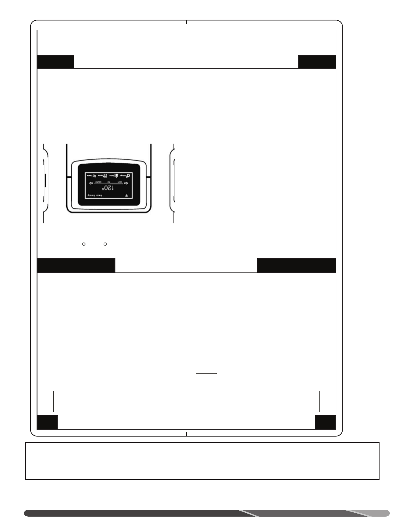
34
FONCTIONNEMENT
Avant de mettre en marche ce chauffe-eau, lisez et suivez toutes les instructions indiquées sur l’étiquette ci-dessous et sur toutes
les autres étiquettes du chauffe-eau, ainsi que tous les avertissements de ce manuel. Le non-respect de cette directive peut entraîner
le mauvais fonctionnement du chauffe-eau et causer des dommages matériels, de graves blessures ou la mort. Si vous avez de la
difficulté à comprendre les instructions de ce manuel, ARRÊTEZ et obtenez de l’aide auprès d’une personne qualifiée.
POUR VOTRE SÉCURITÉ, VEUILLEZ LIRE AVANT DE METTRE EN MARCHE
DIRECTIVES DE MISE EN MARCHE
COMMENT COUPER L’ARRIVÉE DE GAZ À L’APPAREIL
AVERTISSEMENT: Si ces directives ne sont pas suivies exactement, un incendie ou une
explosion risque d’en résulter, causant des dégâts à la propriété, des blessures ou la mort.
A. Cet appareil est équipé d’un dispositif d’allumage
qui allume automatiquement la veilleuse. NE PAS
tenter d’allumer la veilleuse á la main.
B. AVANT DE METTRE CET APPAREIL EN SERVICE -
Renifler tout autour de l’appareil pour déceler une
odeur de gaz. S’assurer de renifler au niveau du
sol parce que certains gaz sont plus lourds que l’air
et peuvent s’accumuler au niveau du sol.
QUE FAIRE SI L’ON SENT UNE ODEUR DE GAZ
● Ne pas tenter d’allumer d’appareil.
● Ne pas toucher d’interrupteurs électriques; ne
pas utiliser les téléphones se trouvant dans
l’édifice.
● Appeler immédiatement votre fournisseur de gaz
de chez un voisin. Suivre les directives du
1. ARRÊTEZ! LIRE LES DIRECTIVES DE SÉCURITÉ
CI-DESSUS, SUR CETTE ÉTIQUETTE.
7. LA TEMPÉRATURE DE L’EAU EST RÉGLÉE
APPROXIMATIVEMET Á 49 C (120 F). RÉGLER
LE THERMOSTAT À LA TEMPÉRATURE VOULUE.
ATTENTION: DE L’EAU PLUS CHAUDE AUGMENTE
LE RISQUE DE BLESSURES PAR ÉBOUILLANTAGE.
CONSULTER LE MANUEL D’INSTRUCTIONS AVANT
DE CHANGER LA TEMPÉRATURE.
AVERTISSEMENT: COUPER L’ALIMENTATION
ÉLECTRIQUE AVANT TOUT ENTRETIEN.
2. PLACER LE CONTACTEUR «ON/OFF» (MARCHE-
ARRÊT) PRÉS DE L’AFFICHEUR DU CONTRÔLE
SUR LA POSITION «OFF» (ARRÊT).
3. CET APPAREIL EST ÉQUIPÉ D’UN DISPOSITIF
D’ALLUMAGE QUI ALLUME AUTOMATIQUEMENT
LE BRÛLEUR.
NE PAS TENTER D’ALLUMER LA VEILLEUSE À LA MAIN
4. SI VOUS SENTEZ UNE ODEUR DE GAZ, ARRÊTEZ-
VOUS! SUIVRE LA RUBRIQUE «B» DES DIRECTIVES
DE SÉCURITÉ DE L’ÉTIQUETTE CI-DESSUS.
5. METTRE L’APPAREIL SOUS TENSION AVEC LE
CONTACTEUR SITUÉ À GAUCHE DE L’AFFICHEUR
DU CONTRÔLE.
6. SI L’APPAREIL NE FONCTIONNE PAS, SUIVRE
LES DIRECTIVES INDIQUANT «COMMENT
COUPER L’ARRIVÉE DE GAZ À L’APPAREIL».
1. COUPER L’ALIMENTATION ÉLECTRIQUE À
L’APPAREIL AVANT D’EFFECTUER TOUT ENTRETIEN.
2. TOURNER LE «BOUTON DE LA SOUPAPE MANUELLE
DE GAZ» À LA POSITION «OFF» (ARRÊT).
C. Utiliser uniquement la main pour tourner le bouton de
contrôle du gaz. Ne jamais utiliser d’outils. Si le bouton
ne tourne pas à la main, ne pas tenterde le réparer,
appeler un technicien de serice qualifié. Le fait de
forcer la manette ou tenter de la réparer peut
déclencher une explosion ou un incendie.
D. Ne pas utiliser cet appareil s’il a été plongé dans l’eau,
même partiellement. Appeler immédiatement un
technicien de service qualifié qui inspectra l’appareil
et remplacera toute pièce du système de contrôle et
toute commande ayant été plongée dans l’eau.
fournisseur de gaz.
● Si vous ne pouvez rejoindre le fournisseur de
gaz, appelez le service des pompiers.
33
A. Emplacement du chauffe-eau
Près des emplacements de ventilation
À l’intérieur et à l’abri du gel
Dégagement approprié des surfaces combustibles
Apport d’air frais ne contient pas de particules corrosives ou
de vapeurs inflammables
Espace suffisant pour l’entretien du chauffe-eau
Chauffe-eau protégé contre les dommages causés par l’eau
B. Alimentation en eau
Réservoir complètement rempli d’eau
Tout l’air est purgé du chauffe-eau et des canalisations
Tous les raccords d’eau sont étanches
C. Alimentation en gaz
Canalisation d’alimentation en gaz munie d’un robinet
d’arrêt, d’un raccord-union et d’un collecteur de sédiments
Dia. min. canalisatin: 1/2 po
Vérification de l’étanchéité des conduites de gaz et raccords
avec solution d’eau et de savon
Utilisation d’un composé d’étanchéité pour filets homologué
D. Soupape de sûreté
Tuyau de décharge dirigé vers un drain ouvert approprié
Tuyau de décharge protégé du gel
E. Ventilation
Chauffe-eau ventilé par un conduit distinct, séparé de ceux
des autres appareils
Tous les raccords des conduits d’apport d’air et
d’évacuation sont solidement assemblés
Conduits d’apport d’air et d’évacuation supportés à
intervalles réguliers
Terminaison d’évacuation ne se termine pas à proximité
ou au-dessus d’un point pouvant être endommagé par
l’humidité s’en dégageant
Tube de drainage fixé au silencieux si requis. Sinon,
assurez-vous que le chapeau est en place
F. Condensation
Collecteur de condensation installé et amorcé.
L’ensemble de neutralisation des condensats est installé (si
requis).
G. Alimentation électrique
Raccordement électrique effectué (120 VCA)
Raccords électriques solidement effectués
Le chauffe-eau est correctement mis à la masse, polarité
électrique respectée
LISTE DE VÉRIFICATION DE L’INSTALLATION
Pour connaître la capacité maximale des conduites de gaz au Canada, reportez-vous à la norme CAN/CSA B149.1. Gaz naturel: Tableaux A.1 à A.17. Propane: Tableaux
B.1 à B.12.
Tableau des capacités
Installation aux États-Unis
Capacité maximale d’un tuyau, en pi³ de gaz par heure pour des pressions de gaz de 0,5 psig ou moins et une chute de pression de 0,3 po colonne d’eau
Basé sur une densité relative de 0,60 pour le gaz naturel; si du propane d’une densité de 1,5 est utilisé, multiplier la capacité par 0,63
Dia. nominale, tuyau
en acier (po)
Diamètre interne (po)
Longueur de tuyau, pi
10 20 30 40 50 60 70 80 90 100 125 150 175 200
1/2 0,622 132 90 73 62 55 50 46 43 40 38 34 31 28 26
3/4 0,824 278 190 152 130 115 105 96 90 84 79 72 64 59 55
1 1,049 520 350 285 245 215 195 180 170 160 150 130 120 110 100
1-1/4 1,380 1050 730 590 500 440 400 370 350 320 305 275 250 225 210
1-1/2 1,610 1600 1100 890 760 670 610 560 530 490 460 410 380 350 320
2 2,067 3050 2100 1650 1450 1270 1150 1050 990 930 870 780 710 650 610
2 1/2 2,469 4800 3300 2700 2300 2000 1850 1700 1600 1500 1400 1250 1130 1050 980
3 3,068 8500 5900 4700 4100 3600 3,250 3000 2,800 2600 2500 2200 2000 1850 1700
4 4,026 17 500 12 000 9700 8300 7400 6800 6200 5800 5400 5100 4500 4100 3800 3500
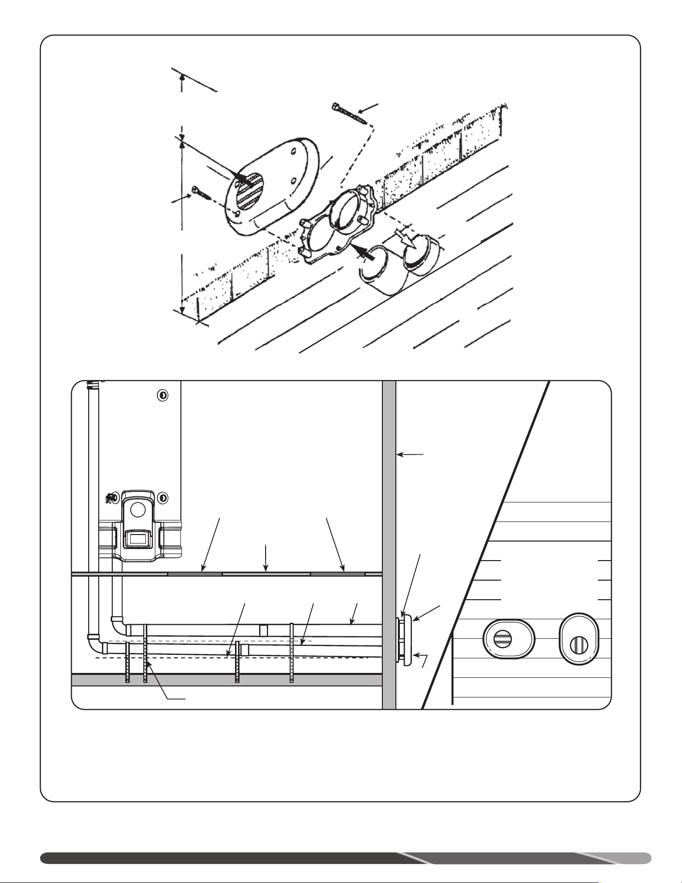
32
Autres installations à l’horizontale
D’autres ensembles de ventilation horizontaux de 2 et 3 po sont offerts sur le marché. Veuillez suivre
les instructions d’installation fournies avec ces ensembles pour réaliser leur installation.
Ensemble de termi-
naison plates
(la terminaison peut
être tournée)
Évac.
Évacuation
Kit de
terminaisons
plates
Prise d’air
Conduit
d’apport
d’air
Conduit
d’évacuation
Pente ascendante vers
la terminaison
Cintre de soutien
Panneau d’accès
pour inspection
(optionnel)
Panneau d’accès
pour inspection
(optionnel)
Plafond
Mur
12 po min. d’un
surplomb
Installer à une hauteur d’au moins 12 po (30 cm)
au-dessus de la limite de neige ou du niveau du
sol (sélectionner la plus grande hauteur).
Vis 1 po
(4 req.)
Vis 2 po
(4 req.)
Évacuation
Couvercle
Plaque
de termi-
naison
Évacuation
Air combu-
rant
INSTALLATION
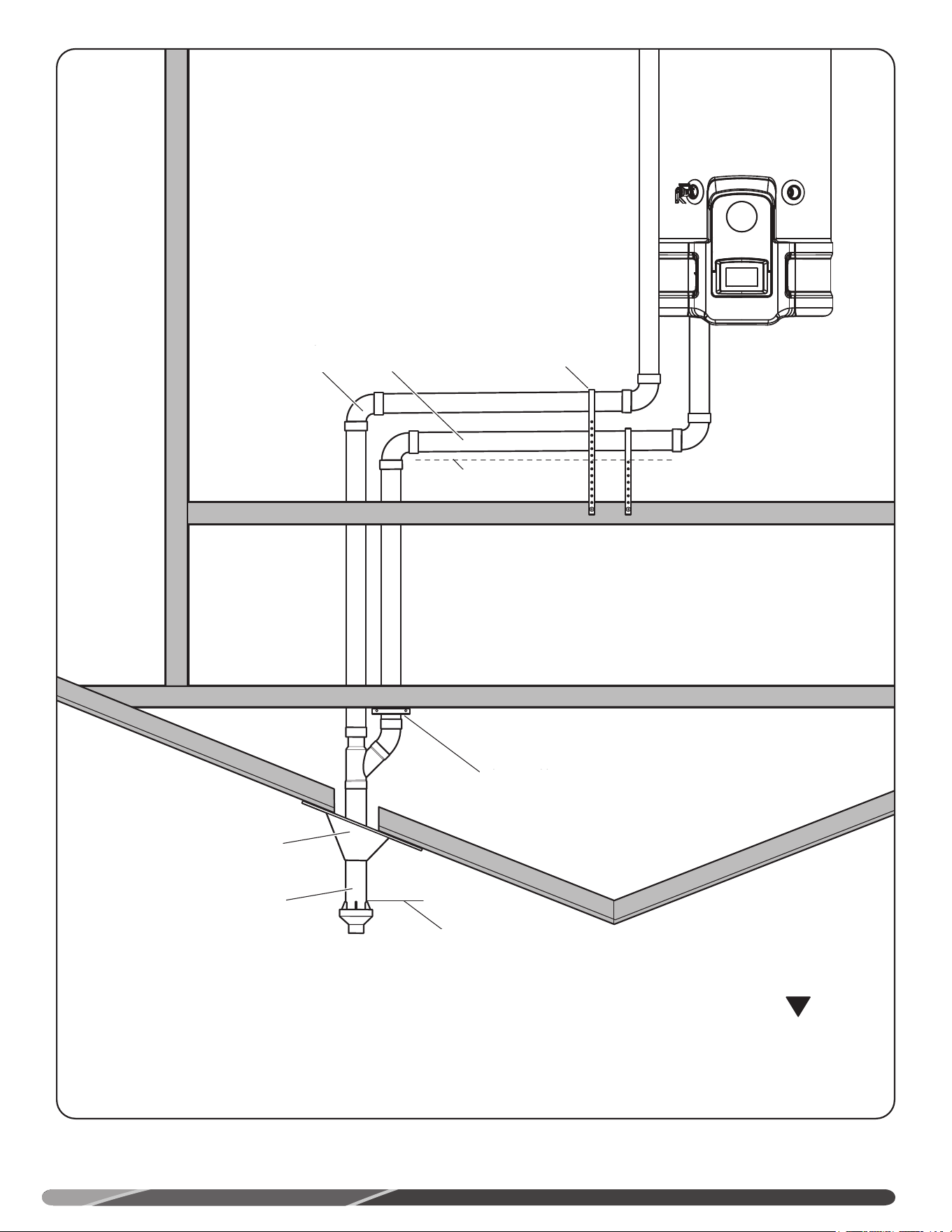
31
Autre terminaison verticale
D’autres ensembles de ventilation verticaux sont offerts sur le marché. Veuillez suivre les instructions
d’installation fournies avec ces ensembles pour réaliser leur installation.
AVERTISSEMENT:
Il ne faut jamais raccorder entre eux les conduits d’apport d’air et d’évacuation.
Support Hanger
Adjustable Roof Flashing
Support Clamp
Air Intake
Pipe
Exhaust Vent
Pipe
Minimum Clearance 18 inches above roof
Concentric Vent Termination
Upward slope 1/8” per foot
(10mm per meter) minimum
NOTE:
dans une installation à ventilation verticale,
veuillez installer un dispositif d’évacuation de
la condensation approprié.
INSTALLATION
!
Dégagement minimum de
18 po (457 mm) au-dessus du toit
Terminaison de ventilation concentrique
Solin de toit ajustable
Anneau de support
Pente ascendante 1/8 po/pied
(10 mm /mètre) minimum
Sangle de support
Apport d’air
Évacuation
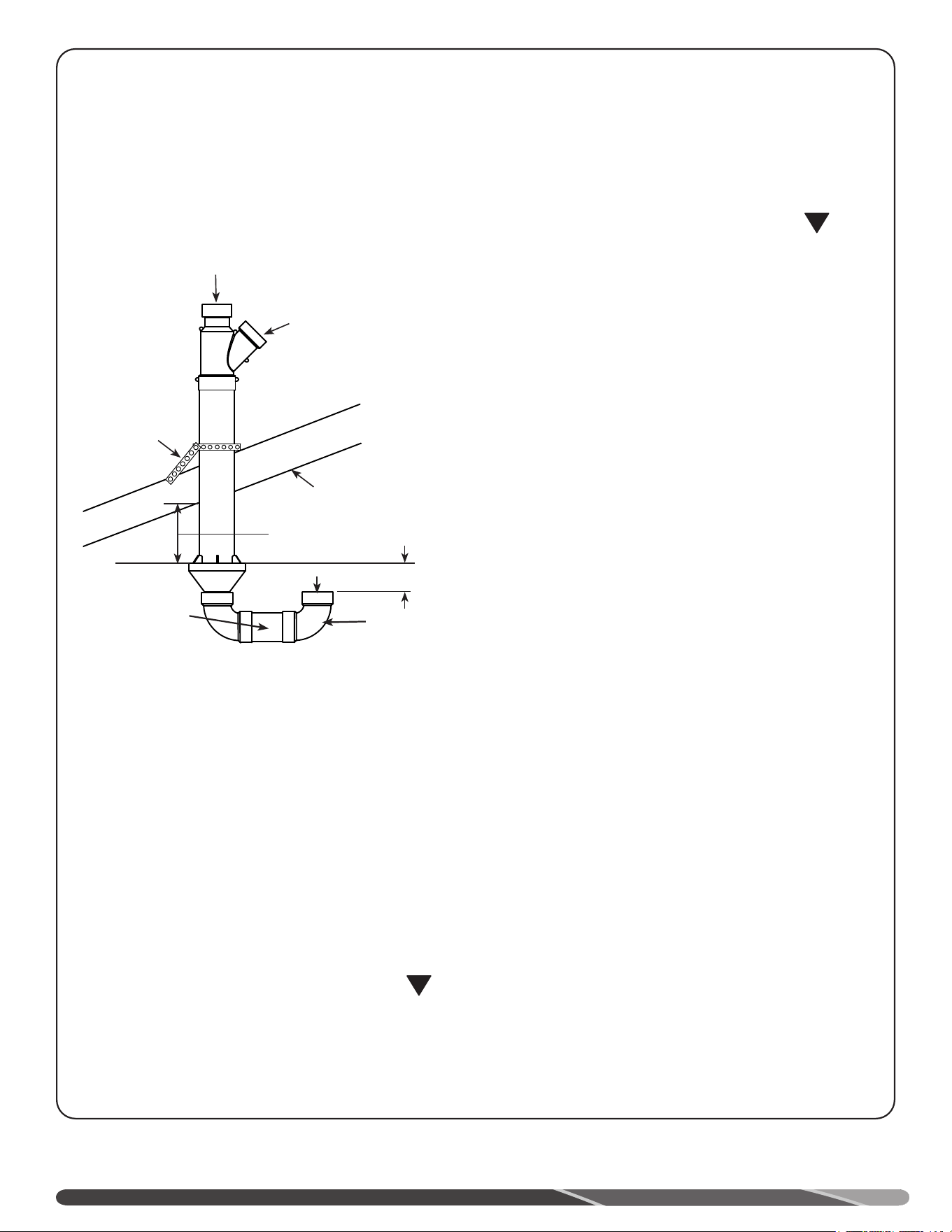
30
!
!
ÉTAPE 5:
De l’extérieur du bâtiment, insérez le conduit de ventilation
dans le conduit d’apport d’air et fixez-le au chapeau. De
l’intérieur du bâtiment, fixez le raccord en "Y" au conduit
d’apport d’air (voir figures sur cette page).
ÉTAPE 6:
Complétez l’installation du reste du système de ventilation
conformément aux instructions du présent manuel.
INSTALLATION À
LA VERTICALE
ÉTAPE 1:
Découpez l’ouverture de diamètre approprié dans le toit;
voir mesure "D" dans le tableau; installez le solin (non
fourni) autour du conduit de PVC.
ÉTAPE 2:
De l’intérieur du bâtiment, insérez le conduit de plus grand
diamètre à travers le solin; assurez-vous de l’absence
d’isolant ou de débris dans le conduit. Assurez-vous que la
terminaison est positionnée respecte le dégagement requis
au-dessus de la terminaison d’apport d’air.
ÉTAPE 3:
Fixez en place le conduit d’apport d’air à l’aide d’une
sangle perforée (non fournie) ou par tout autre moyen (voir
la figure Installation d’apport d’air à la verticale sur cette
page).
ÉTAPE 4:
Nettoyez et collez le chapeau au conduit de plus petit
diamètre. Nettoyez et collez le coude à 90° au chapeau.
Nettoyez et collez le manchon en PVC (non fourni) et le
coude à 90°, comme illustré à la figure Installation d’apport
d’air à la verticale sur cette page. Le raccordement des
composantes en PVC à l’aide de vis n’est pas obligatoire.
NOTE: s’il est prévu que l’assemblage doit être amovible
pour le nettoyage; il est possible d’utiliser une vis à
métal pour fixer le chapeau au plus petit conduit de PVC
(évacuation).
AVERTISSEMENT:
Pour fixer le chapeau à l’aide d’une vis, percez un avant-
trou légèrement plus grand que la vis dans le chapeau
et un avant-trou légèrement plus petit dans le conduit
de PVC afin d’éviter de le fendre. Pour fixer le chapeau
à l’aide d’une vis, percez un avant-trou légèrement plus
grand que la vis dans le coude à 90° et un avant-trou
légèrement plus petit dans le chapeau. Le fendillement
du conduit en PVC causera une défaillance du système,
ce qui entraînera la recirculation des produits de
combustion. Le non-respect de cet avertissement peut
entraîner
de graves blessures ou la mort.
AVERTISSEMENT:
NE PAS faire fonctionner ce chauffe-eau sans sa
terminaison; cela risque de provoquer la recirculation
des gaz de combustion. Cela risque aussi de permettre
à l’eau d’entrer dans le système de ventilation, ce qui
pourrait endommager le chauffe-eau. Le non-respect de
cet avertissement peut endommager l’appareil et peut
entraîner des dommages matériels, de graves blessures
ou la mort.
ÉTAPE 5:
À partir du toit, insérez le conduit d’évacuation dans le plus
grand conduit d’apport d’air et collez le chapeau au conduit
d’apport d’air. De l’intérieur du bâtiment, collez le raccord
en "Y" au conduit d’apport d’air (voir figure ci-dessous).
(Voir page suivante pour plus de détails)
Évacuation
Sangle (non
fournie avec
le chauffe-
eau)
Raccord d’air frais
du chauffe-eau
Conduit d’évacuation
du chauffe-eau
Manchon en
PVC (non fourni)
Coude à 90°
(non fourni)
Min. 18 po (457 mm)
au-dessus du toit ou
de la limite de neige.
Min. 12 po
(305 mm)
INSTALLATION D’APPORT D’AIR À LA VERTICALE
INSTALLATION
Toit
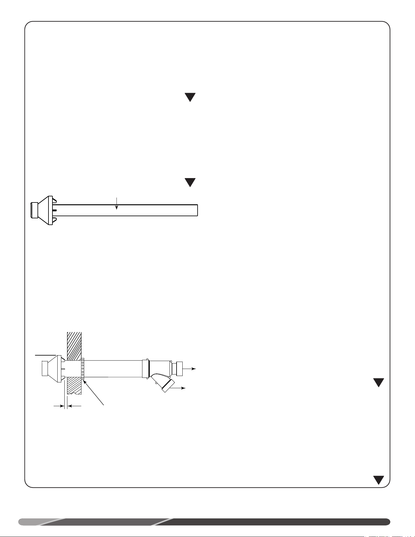
29
AVERTISSEMENT
Les présentes instructions sont destinées à des techniciens
qualifiés pour l’installation, le réglage et l’utilisation de cet
ensemble de ventilation. Lisez attentivement les présentes
instructions avant de procéder à l’installation, au réglage
ou de faire fonctionner cet appareil. Tout manquement
aux présentes instructions pourrait se traduire par une
installation, un réglage, une réparation ou un entretien
inadéquats, ce qui pourrait causer un incendie, une
électrocution, des dommages matériels, de graves blessures
ou la mort.
AVERTISSEMENT:
Cet ensemble doit uniquement être utilisé pour
l’approvisionnement en air et l’évacuation des gaz de
combustion de chauffe-eau au gaz à évacuation directe et
forcée (PDV). NE PAS utiliser cet ensemble de terminaison
avec tout autre appareil. Le non-respect de cet avertissement
peut causer un incendie pouvant entraîner de graves
blessures ou la mort.
EMPLACEMENT:
L’ensemble de terminaison concentrique peut être installé à
l’horizontale (mur) ou à la verticale (toit). Déterminez le meilleur
endroit de pose avant d’entreprendre l’installation de l’ensemble
de terminaison concentrique.
IMPORTANT:
L’ensemble de terminaison concentrique doit respecter les
exigences suivantes:
• L’ensemble est installé à un endroit où les gaz de
combustion n’endommageront pas une structure située à
proximité.
• L’ensemble est positionné de façon à ce que le vent
ne permettra pas au gaz de combustion aux feuilles, à
la neige ou à d’autres débris d’être repoussés dans le
conduit d’apport d’air.
• L’ensemble est positionné à un endroit où il ne risque pas
d’être endommagé par un projectile.
• L’ensemble est positionné à un endroit où les gaz de
combustion ne risquent pas d’être inhalés.
NOTE: Assurez-vous que les ouvertures d’apport d’air et
d’évacuation sont positionnées au-dessus de la limite de neige
(1 pi / 305 mm).
INSTALLATION À
L’HORIZONTALE
ÉTAPE 1:
Découpez l’ouverture de diamètre approprié dans le mur; voir
mesure "D" dans le tableau; installez le solin (non fourni) autour
du conduit de PVC.
ÉTAPE 2:
De l’intérieur, insérez le conduit d’apport d’air à travers le solin;
il doit y avoir un dégagement maximal de 1 po entre la surface
du mur et le chapeau (voir figure suivante). Assurez-vous de
l’absence d’isolant ou de débris dans le conduit.
ÉTAPE 3:
Fixez en place le conduit d’apport d’air à l’aide d’une sangle
perforée (non fournie) ou par tout autre moyen (voir figure
ci-dessus).
ÉTAPE 4:
Nettoyez et collez le chapeau au conduit de plus petit diamètre.
Note: s’il est prévu que le chapeau devra être ultérieurement
enlevé pour un nettoyage; il est possible d’utiliser une vis à
métal pour fixer le chapeau au conduit de PVC.
AVERTISSEMENT:
Pour fixer le chapeau à l’aide d’une vis, percez un avant-
trou légèrement plus grand que la vis dans le chapeau et
un avant-trou légèrement plus petit dans le conduit de PVC
afin d’éviter de le fendre. Le fendillement du conduit en PVC
causera une défaillance du système, ce qui entraînera la
recirculation des produits de combustion. Le non-respect de
cet avertissement peut entraîner de graves blessures ou la
mort.
AVERTISSEMENT:
NE PAS faire fonctionner ce chauffe-eau sans son chapeau;
cela risque de provoquer la recirculation des gaz de
combustion. Cela risque aussi de permettre à l’eau d’entrer
dans le système de ventilation, ce qui pourrait endommager
le chauffe-eau. Le non-respect de cet avertissement
peut endommager l’appareil et peut entraîner un
dysfonctionnement, de graves blessures ou la mort.
Système de ventilation
1 po max.
Raccord
d’air frais du
chauffe-eau
Sangle (non fournie
avec le chauffe-eau)
Conduit d’évacuation
du chauffe-eau
Min. 12 po (305
mm) au-dessus
du sol ou de la
limite de neige.
!
!
!
!
INSTALLATION D’APPORT D’AIR À L’HORIZONTALE
INSTALLATION
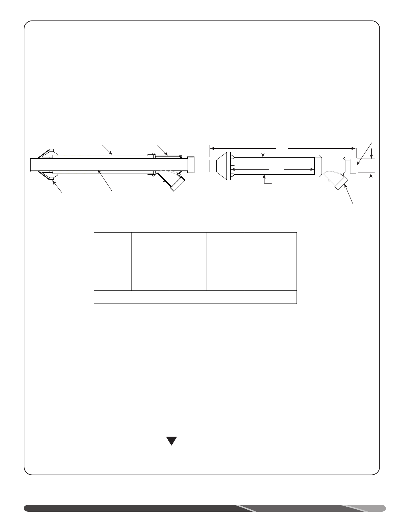
28
PROCÉDURE
Une installation, un réglage, une réparation ou un
entretien inadéquat peut causer des dommages
matériels, des blessures ou la mort. Appelez un
installateur qualifié, un centre de service licencié ou
votre fournisseur de service du gaz.
Cet ensemble de terminaison de ventilation doit
uniquement être utilisé avec ce chauffe-eau. NE PAS
utiliser cet ensemble de terminaison avec tout autre
appareil. L’utilisation de cet ensemble avec tout autre
chauffe-eau ou appareil peut entraîner des dommages
matériels, de graves blessures ou la mort.
AVIS:
Les joints de l’ensemble de ventilation concentrique
doivent être collés.
!
ATTENTION:
NE PAS faire fonctionner ce chauffe-eau sans sa
terminaison; cela risque de provoquer la recirculation
des gaz de combustion. De l’eau pourrait s’accumuler
dans le plus large conduit
(apport d’air) et s’écouler jusqu’à la chambre de
combustion. Le non-respect de cet avertissement peut
entraîner un mauvais fonctionnement, des dommages
matériels, de graves blessures ou la mort.
NE PAS utiliser les raccords fournis pour allonger les
conduits. Cela ajoutera des restrictions et entraînera un
mauvais fonctionnement des pressostats du chauffe-
eau.
Installation:
1. Découvrez les diverses composantes de l’ensemble de ventilation concentrique (voir tableau ci-dessus).
2. Déterminez le meilleur endroit de pose.
3. Découpez l’ouverture de diamètre recommandé en fonction du diamètre du conduit comme indiqué dans les tableaux
ci-dessus – Dim. “D”.
4. Assemblez partiellement l’ensemble de ventilation ainsi:
a. Collez les raccords concentriques Y au conduit de plus grand diamètre (voir tableau ci-dessus).
b. Collez la terminaison au conduit de plus petit diamètre (voir tableau ci-dessus).
Apport d’air, PVC
"C"
"D"
"A"
Évacuation, PVC
"C"
Raccord
concentrique "Y"
Diamètre conduit
"D"
Diamètre conduit "E"
Chapeau de
pluie
"B"
Installation de terminaison de ventilation concentrique
INSTALLATION
Dimensions nominale PVC
“A” “B” “C” “D”
Kit 2 po 33,5 po 17,65 po 2,68 po 3,5 po
Kit 3 po 39,5 po 22,38 po 3,83 po 4,5 po *
Kit 4 po 53,75 po 34,8 po 4 po 6 po
*Diamètre de l’ouverture pour conduit 4 po en PVC: 5 po (127 mm)
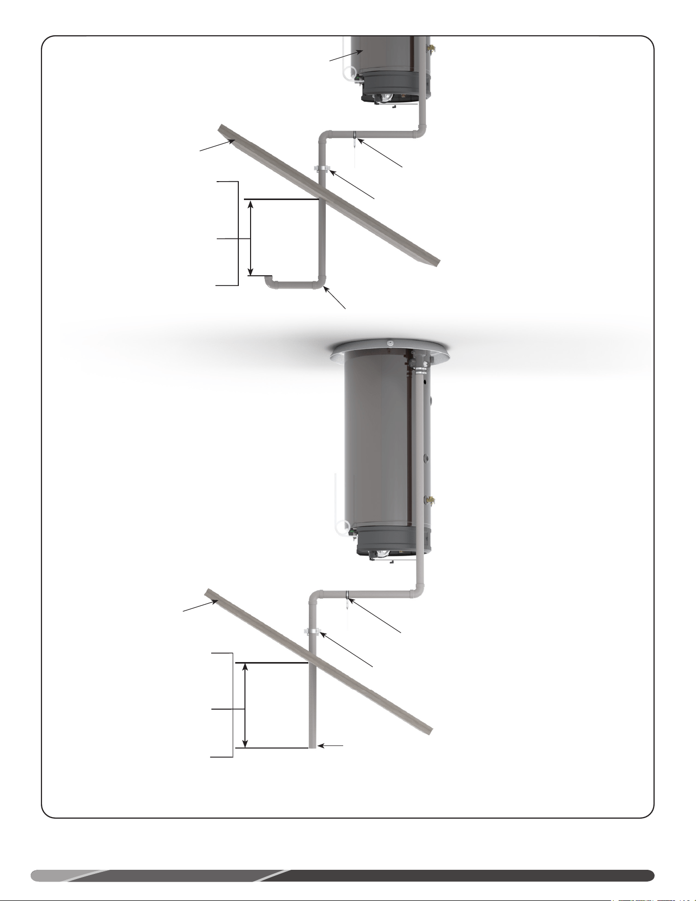
27
Terminaison d’évacuation droite
Support
Chauffe-
eau
Il est recommandé de supporter la sec-
tion horizontale
Min. 12 po (305 mm) aux
États-Unis et Min. 18 po (457
cm) au Canada (au-dessus
du toit).
Min. 12 po (305 mm) au-des-
sus de la limite de neige.
Max. 24 po (610 mm) au-des-
sus du toit (sans support
additionnel).
Installation-type à la verticale, évacuation forcée (PV)
INSTALLATION
Chauffe-eau
Support
Terminaison d’évacuation
Autre configuration
de ventilation
verticale, évacuation
vers le bas;
préférable dans les
climats froids.
Il est recommandé de supporter la
section horizontale
Min. 12 po (305 mm) aux États-
Unis et Min. 18 po (457 cm) au
Canada (au-dessus du toit).
Min. 12 po (305 mm) au-dessus
de la limite de neige.
Max. 24 po (610 mm) au-des-
sus du toit (sans support
additionnel).
Toit
Toit
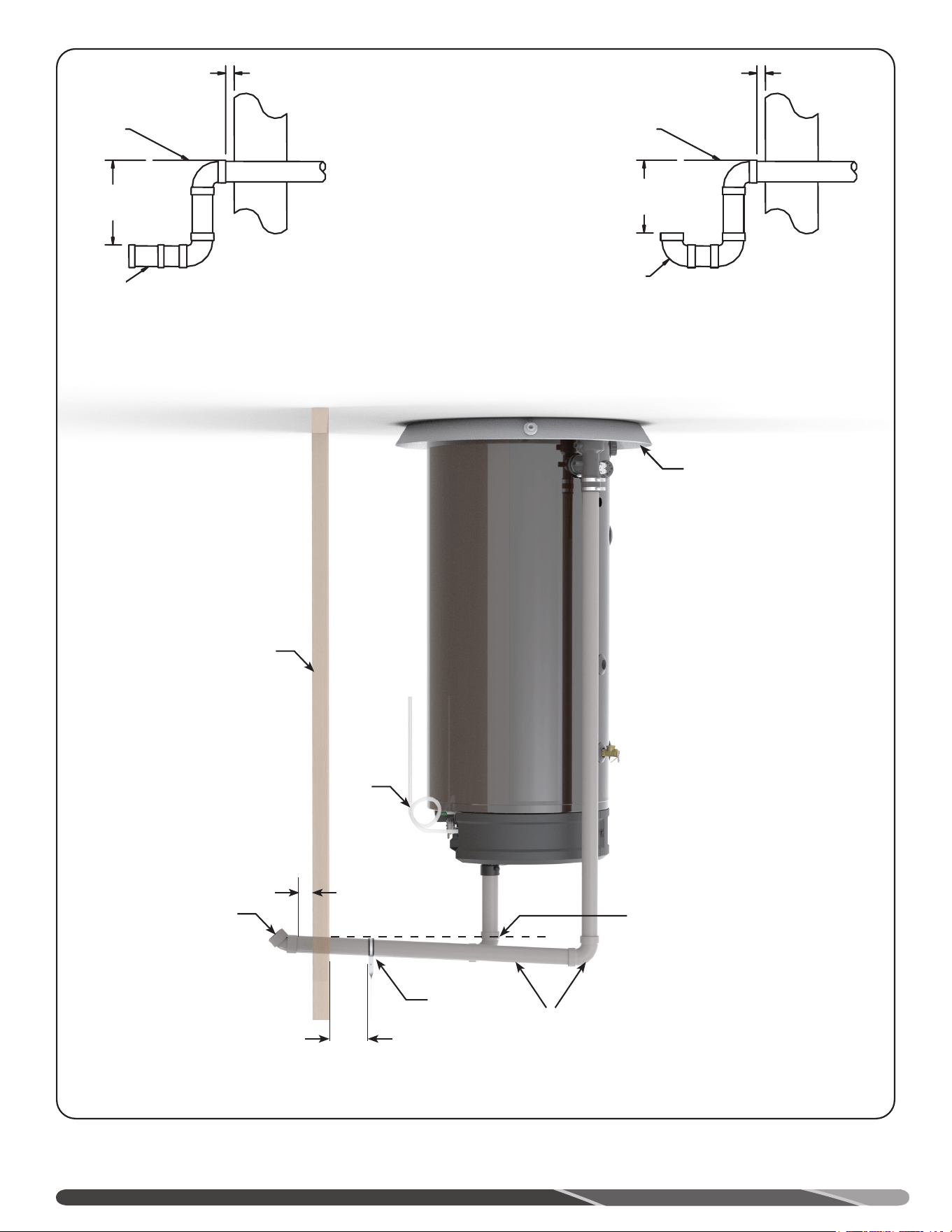
26
Conduit de
2, 3 ou 4 po*
et raccords
Maintenir une pente
descendante d’au
moins 1/8 po par pied
(10 mm par mètre).
Terminaison à 45°
Mur
Tube
de drai-
nage
1 po max.
Support
3 pi (915 mm) max.
Bac d’égouttement
INSTALLATION
Ventilation murale avec faible dégagement au sol:
Lorsqu’il n’est pas possible d’acheminer un conduit de ventilation à une hauteur supérieure à 12 po (305 mm) au-dessus du
sol ou de la limiter anticipée de neige, il faut alors modifier l’installation comme indiqué ci-dessous.
Terminaison
d’apport
d’air à 90°
Terminaison
d’évacuation
"D"
"D"
Niveau du sol
Niveau
du sol
1 po (25 mm)
1 po (25 mm)
"D"
Min. 12 po (305 mm)
au-dessus du sol.
Min. 12 po (305 mm)
au-dessus de la limite
de neige.
Max. 24 po (610 mm)
sans support addition-
nel
Installation-type à l’horizontale, évacuation forcée (PV)
IMPORTANT:
Dans un climat froid, les
conduits de ventilation
doivent maintenir une
pente ascendante.
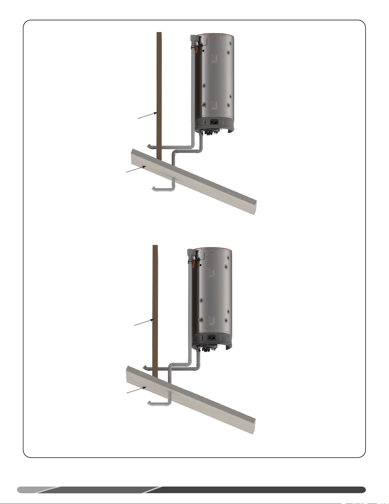
25
Ventilation directe (DV) à la verticale, prise d’air horizontale
INSTALLATION
Toit
Mur
Toit
Mur
Ventilation directe (DV) à l’horizontale, prise d’air verticale
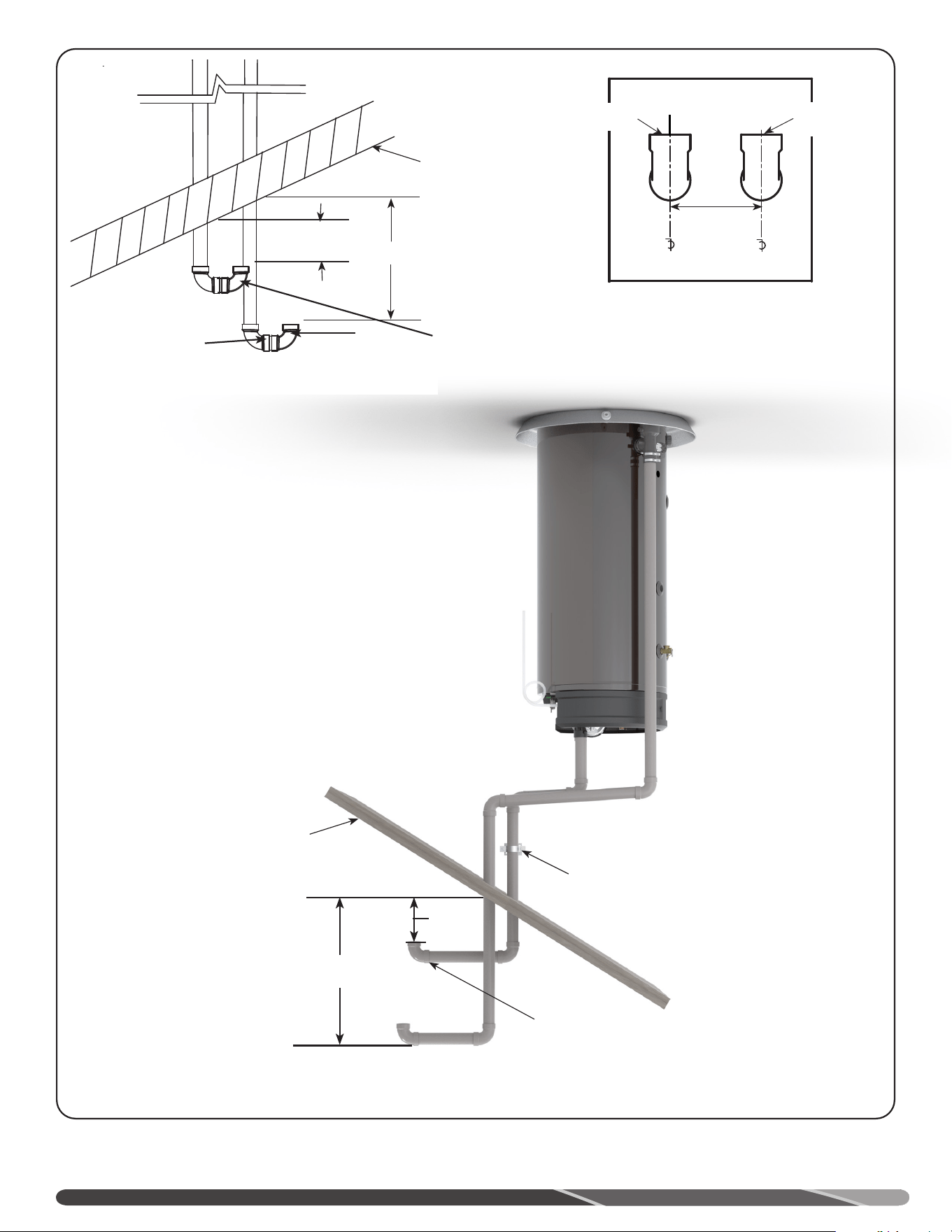
24
Chauffe-
eau
Min. 24 po (610
mm)
(support requis).
Terminaison d’apport d’air à 90°
Support
"D"
Installation-type à la verticale, ventilation directe (DV)
24 po
(610 mm)
min.
Terminaison d’apport
d’air
Terminaison
d’évacuation
-B-
-A-
-B-
d
.008
d
.010
"D"
Min. 12 po (305 mm) aux États-
Unis et Min. 18 po (457 cm) au
Canada (au-dessus du toit)
Min. 12 po (305 mm) au-dessus
de la limite de neige.
Max. 24 po (610 mm) au-des-
sus du toit sans
support additionnel)
Terminaison avec
grille protectrice
1/2 po (13 mm)
anti-vermine insérée.
Dans un climat froid:
utiliser une grille pro-
tectrice ne favorisant
pas la formation de
glace.
Coude
Courte longueur de conduit
"D"
Conduit d’apport d’air
"D"
Écart entre les terminaisons ho-
rizontales ou verticales.
Conduit
INSTALLATION
Toit
Toit
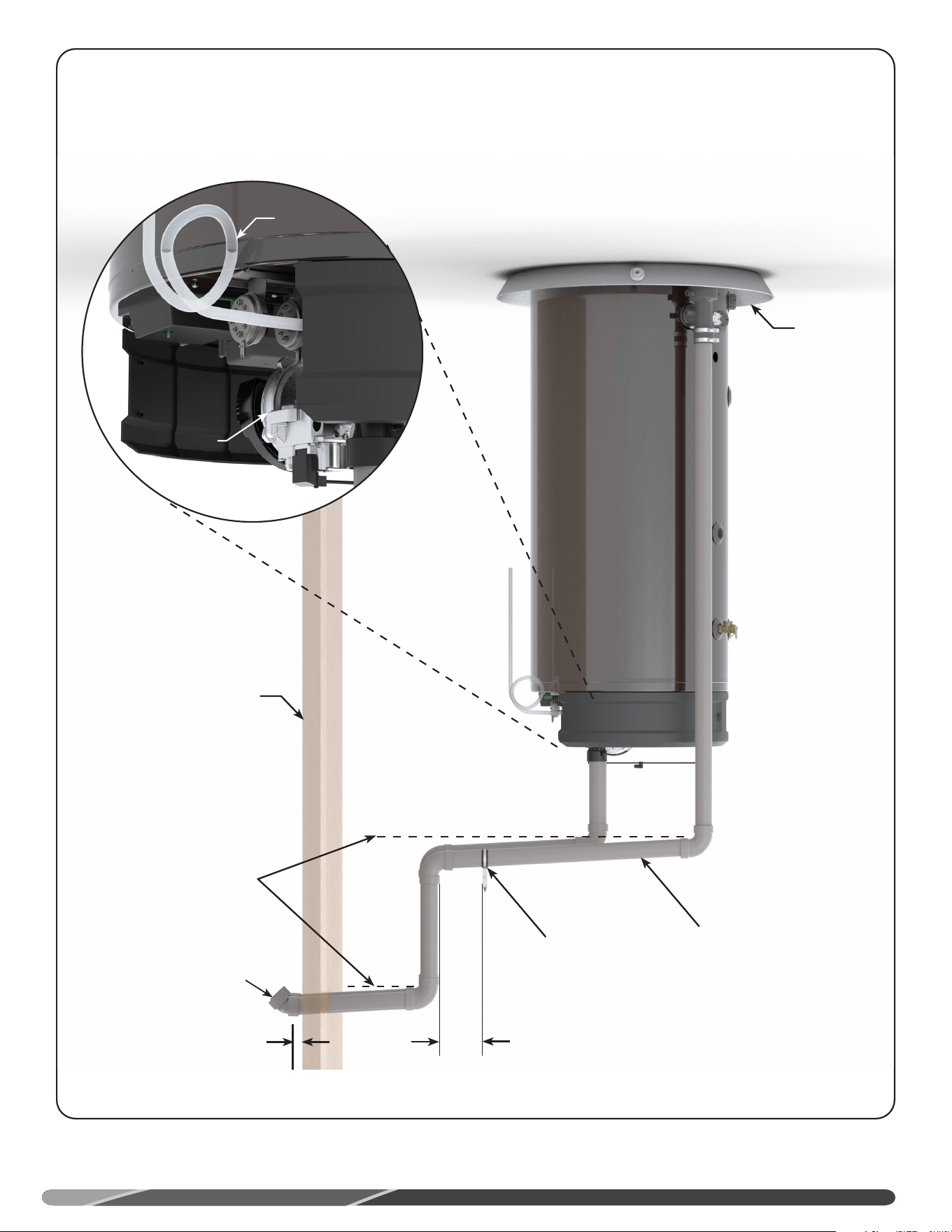
23
Dégagements de la terminaison, évacuation forcée (PV)
Conduit de 2, 3 ou
4 po et raccords
Support
3 pi (915 mm) max.
Terminaison à 45°
Maintenir une pente ascen-
dante d’au moins 1/4 po
par pied (10 mm par mètre).
Mur
Chauffe-eau
Bac
d’égouttement
1 po max.
Tube de
drainage
Raccord d’apport
d’air du
ventilateur
• Raccordez un tube flexible en PVC de diamètre intérieur de 1/2 po (ou matériau équiva-
lent), au raccord de drainage. AVIS: la longueur du tube flexible doit être suffisante pour
atteindre un drain de plancher, l’extérieur du bâtiment ou tout autre dispositif de collecte
de la condensation (reportez-vous à vos codes locaux).
• Formez une boucle circulaire et fixez les parties supérieure et inférieure de la boucle avec
du fil métallique ou des attaches de plastique, comme illustré. NE PAS pincer le tube
flexible. Le tube ne doit pas être pincé ni son diamètre réduit sur toute sa longueur.
• Remplissez le tube de drainage d’eau pour empêcher un retour des gaz de combustion
vers la maison.
• Acheminez l’extrémité du tube flexible vers un drain de plancher, l’extérieur du bâtiment
ou tout autre dispositif de collecte de la condensation (reportez-vous à vos codes locaux).
Installation-type à l’horizontale, ventilation directe (DV)
INSTALLATION
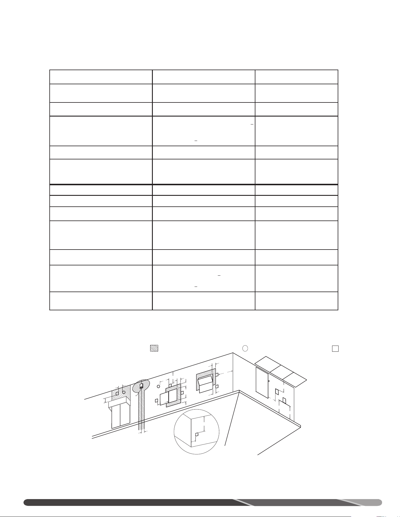
22
INSTALLATION
D
V
V
E
FIXED
CLOSED
O
P
ERA
BL
E
O
PE
R
A
BL
E
FIXE
D
CLOSED
v
v
B
L
F
C
B
v
v
v
X
B
B
B
A
J
C
I
H
X
v
M
K
v
G
A
Respectez les exigences qui suivent pour sélectionner un positionnement approprié des terminaisons
de ventilation d’un chauffe-eau à ventilation directe.
V
TERMINAISON D’ÉVACUATION
X
TERMINAISON D’APPORT D’AIR
SURFACES OÙ LA TERMINAISON N’EST PAS PERMISE
EMPLACEMENT D’UNE TERMINAISON MURALE, ÉVACUATION FORCÉE (PV)
Installation au Canada
1
Installation aux États-Unis
2
A= Dégagement au-dessus du niveau du
sol, d’une véranda, d’un porche, d’une
terrasse ou d’un balcon.
12 po (305 mm) 12 po (305 mm)
B= Dégagement autour des fenêtres ou
des portes qui peuvent être ouvertes.
6 po (150 mm) pour appareils < 10 000 BTU/h
(3 kW), 12 po (305 mm) pour appareils > 10 000
BTU/h (3 kW) et < 100 000 BTU/h (30 kW), 36 po
(910 mm) pour appareils > 100 000 BTU/h (30 kW).
4 pi (1,2 m) au-dessous ou à côté de l’ouverture; 1 pi
(305 mm) au-dessus de l’ouverture.
C= Dégagement d’une fenêtre qui ne
s’ouvre pas.
0 po (0 mm) 0 po (0 mm)
D= Dégagement vertical sous un soffite
ventilé, si le centre de la terminaison
est situé à une distance horizontale
inférieure à 2 pi (610 mm).
12 po (305 mm) 12 po (305 mm)
E= Dégagement de tout soffite non
ventilé.
12 po (305 mm) 12 po (305 mm)
F= Dégagement de tout coin extérieur. 24 po (61 mm) 24 po (61 mm)
G= Dégagement de tout coin intérieur. 18 po (457 mm) 18 po (457 mm)
1 En conformité avec l’édition en vigueur de CSA B149.1, Code d’installation du gaz naturel et du propane.
2 En conformité avec l’édition en vigueur de ANSI Z223.1/NFPA 54, National Fuel Gas Code.
+ Un conduit de ventilation ne doit pas se terminer directement au-dessus d’un trottoir ou d’une entrée pavée située entre
deux logements unifamiliaux et qui les dessert tous les deux.
*Les distances de dégagement doivent respecter les exigences des codes d’installation locaux et celles du fournisseur du
service du gaz.
H= Dégagement de chaque côté d’une
ligne passant par le centre d’un
compteur ou du régulateur d’abonné.
au-dessus de ceux-ci.
Dégagement horizontal de 3 pi (91 cm) d’un
compteur ou d’un régulateur, jusqu’à une hauteur de
15 pi (4,57 m).
3 pi (910 mm) à une hauteur inférieure à 15 pi (4,6
m)
I= Dégagement de la soupape de
décharge du régulateur d’abonné.
3 pi (91 cm) 3 pi (910 mm)
J= Dégagement d’une terminaison
d’apport d’air non mécanique du
bâtiment ou de la terminaison d’apport
d’air comburant de tout autre appareil.
6 po (150 mm) pour appareils < 10 000 BTU/h (3
kW), 12 po (305 mm) pour
appareils > 10 000 BTU/h (3 kW) et
< 100 000 BTU/h (30 kW), 36 po (910 mm) pour
appareils > 100 000 BTU/h (30 kW).
4 pi (1,2 m) au-dessous ou à côté de l’ouverture; 1 pi
(305 mm) au-dessus de l’ouverture.
K = Dégagement de toute prise d’air frais
mécanique.
6 pi (1,83 m) 3 pi (910 mm) au-dessus, si à moins de 10 pi (3 m)
horizontalement.
L = Dégagement au-dessus d’un trottoir
pavé ou d’une entrée pavée sur une
propriété publique.
7 pi (2,13 m)+ 7 pi (2,13 m)+
M= Dégagement sous une véranda, un
porche, une terrasse ou un balcon.
Non permis Non permis
Dégagements de la terminaison, évacuation forcée (PV)
Fixe,
fermée
Fixe,
fermée
S'ouvre
S'ouvre

21
INSTALLATION DU SYSTÈME DE VENTILATION – Avant
d’entreprendre l’installation du système de ventilation,
prenez connaissance des instructions et avertissements de
la section “Raccordement des conduits et raccords”.
INSTALLATION À ÉVACUATION FORCÉE (PV) − Une
installation à évacuation forcée tire l’air frais de l’intérieur
du bâtiment. L’évacuation des gaz de combustion peut
s’effectuer par un conduit de 2 po (51 mm), 3 po (76 mm)
ou 4 po (102 mm) en PVC, en CPVC, en PP ou en ABS (non
permis au Canada). Ce chauffe-eau est fourni avec un
coude muni d’une grille (terminaison d’apport d’air) et un
raccord d’évacuation (terminaison d’évacuation).
NOTE: Des ensembles d’évacuation forcée (PV) en PP
flexible sont offerts en diamètres de 2 et 3 po. Ces
ensembles s’utilisent uniquement en configuration
verticale.
AVIS:
L’utilisation de conduits à âme alvéolaire en PVC
(ASTM-F891), en ABS Schedule 40, DWV à âme alvéolaire
(ASTM-F628) ou en Radel (polyphenylsulfone) dans un
système de ventilation non métallique, est interdite.
Lorsque le conduit d’évacuation est orienté à l’horizontale,
il est important qu’aucune condensation ne puisse s’y
accumuler. À cette fin, le conduit doit maintenir une
faible pente ascendante de 1/4 po par pied. Le conduit
d’évacuation doit être supporté tous les 5 pi (1,5 m) sur
ses sections verticales, et tous les 3 pi (910 mm) sur ses
sections horizontales.
Le défaut d’adéquatement supporter le conduit
d’évacuation avec des sangles et des collets peut entraîner
des dommages au système de ventilation et au chauffe-
eau.
• NE PAS positionner à proximité de soffites ventilés, d’évents de vides sanitaires ou de tout endroit où la condensation
ou la vapeur pourrait constituer une nuisance, représenter un danger ou causer des dommages matériels.
• NE PAS positionner la terminaison d’évacuation là où de la condensation ou de la vapeur pourrait causer des dommages
matériels ou nuire au bon fonctionnement d’un régulateur de pression, d’une soupape de sûreté ou de tout autre
équipement.
• NE PAS positionner la terminaison d’évacuation au-dessus d’un passage public ou d’un trottoir où un écoulement de
condensation ou un échappement de vapeur pourrait constituer une nuisance ou représenter un danger.
• NE PAS positionner la terminaison d’évacuation à proximité de plantes ou d’arbustes.
INSTALLATION
NOTE: installez selon la plus récente édition du National Fuel Gas Code, du “Code d’installation du gaz naturel et du propane”,
CSA-B149.1 ou des codes locaux applicables.
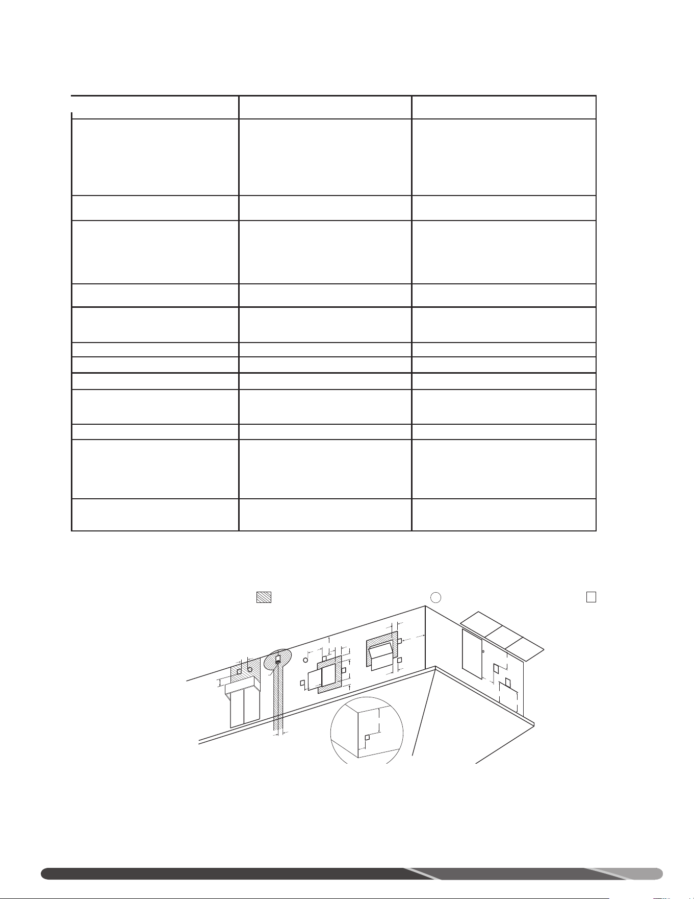
20
INSTALLATION
D
V
V
E
FIXED
CLOSED
O
P
ERA
BL
E
O
PE
R
A
BL
E
FIXE
D
CLOSED
v
v
B
L
F
C
B
v
v
v
X
B
B
B
A
J
C
I
H
X
v
M
K
v
G
A
Respectez les exigences qui suivent pour sélectionner un positionnement approprié des terminaisons
de ventilation d’un chauffe-eau à ventilation directe.
V
TERMINAISON D’ÉVACUATION
X
TERMINAISON D’APPORT D’AIR
Fixe,
fermée
Fixe,
fermée
S'ouvre
S'ouvre
SURFACES OÙ LA TERMINAISON N’EST PAS PERMISE
EMPLACEMENT D’UNE TERMINAISON MURALE, ÉVACUATION DIRECTE ET FORCÉE (PDV)
Installation au Canada
1
Installation aux États-Unis
2
A= Dégagement au-dessus du niveau du sol, d’une
véranda, d’un porche, d’une terrasse ou d’un
balcon.
12 po (305 mm) 12 po (305 mm)
B= Dégagement autour des fenêtres ou des portes qui
peuvent être ouvertes.
• 6 po (150 mm) pour appareils < 10 000 BTU/h
(3 kW)
• 9 po (230 mm) pour appareils > 10 000 BTU/h
(3 kW) et < 50 000 BTU/h (15 kW)
• 12 po (305 mm) pour appareils > 50 000 BTU/h
(15 kW)
• 6 po (150 mm) pour appareils < 10 000 BTU/h
(3 kW)
• 9 po (230 mm) pour appareils > 10 000 BTU/h
(3 kW) et < 100 000 BTU/h (30 kW)
• 36 po (910 mm) pour appareils > 100 000
BTU/h (30 kW)
C= Dégagement d’une fenêtre qui ne s’ouvre pas. 0 po (0 mm) 0 po (0 mm)
D= Dégagement vertical sous un soffite ventilé, si le
centre de la terminaison est situé à une distance
horizontale inférieure à 2 pi (610 mm).
12 po (305 mm) 12 po (305 mm)
E= Dégagement de tout soffite non ventilé. 12 po (305 mm) 12 po (305 mm)
F= Dégagement de tout coin extérieur. 24 po (61 mm) 24 po (61 mm)
G= Dégagement de tout coin intérieur. 18 po (457 mm) 18 po (457 mm)
H= Dégagement de chaque côté d’une ligne passant par
le centre d’un compteur ou du régulateur d’abonné
au-dessus de ceux-ci.
3 pi (910 mm) à une hauteur inférieure à 15 pi
(4,6 m)
3 pi (910 mm) à une hauteur inférieure à 15 pi
(4,6 m)
I= Dégagement de la soupape de décharge du
régulateur d’abonné.
3 pi (910 mm) 3 pi (910 mm)
J = Dégagement d’une terminaison d’apport d’air
non mécanique du bâtiment ou d’une terminaison
d’apport d’air comburant de tout autre appareil.
• 6 po (150 mm) pour appareils < 10 000 BTU/h
(3 kW)
• 9 po (230 mm) pour appareils > 10 000 BTU/h (3
kW) et < 100 000 BTU/h (30 kW)
• 36 po (910 mm) pour appareils > 100 000 BTU/h
(30 kW)
• 6 po (150 mm) pour appareils < 10 000 BTU/h
(3 kW)
• 9 po (230 mm) pour appareils > 10 000 BTU/h
(3 kW) et < 50 000 BTU/h (15 kW)
• 12 po (305 mm) pour appareils > 50 000
BTU/h (15 kW)
K = Dégagement de toute prise d’air frais mécanique. 6 pi (1,83 m)
• 36 po (914 mm) au-dessus, si à moins de 10 pi
(3 m) horizontalement.
L = Dégagement au-dessus d’un trottoir pavé ou d’une
entrée pavée sur une propriété publique.
7 pi (2,13 m)
7 pi (2,13 m) pour les systèmes à tirage mécanique
(appareils de Catégorie I); la terminaison
d’évacuation d’un appareil de Catégorie II et IV ne
peut se trouver au-dessus d’un passage public ou de
tout autre endroit où un écoulement de condensation
ou un échappement de vapeur pourrait constituer une
nuisance ou représenter un danger.
M= Dégagement sous une véranda, un porche, une
terrasse ou un balcon.
12 po (30 cm) ‡ 12 po (30 cm)*
Dégagements de la terminaison, ventilation directe
1)
Conformément à l’édition en vigueur du “Code d’installation du gaz naturel et du propane” CSA B149.1.
2)
Conformément à l’édition en vigueur de ANSI Z223.1/NFPA 54, National Fuel Gas Code.
‡ Permis seulement si le dessous du plancher de la véranda, du porche, de la terrasse ou du balcon est entièrement ouvert sur au moins deux côtés.
* Permis seulement si le dessous du plancher de la véranda, du porche, de la terrasse ou du balcon est entièrement ouvert sur au moins deux côtés.
NOTE: installez selon la plus récente édition du National Fuel Gas Code, du “Code d’installation du gaz naturel et du propane”,
CSA-B149.1 ou des codes locaux applicables.
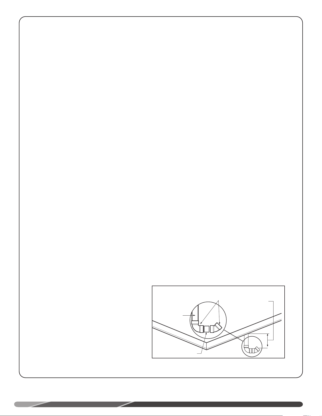
19
VENTILATION À
LA VERTICALE
Déterminez l’emplacement de la terminaison d’évacuation
puis percez des ouvertures permettant le passage
du conduit à travers le toit et le plafond. Complétez
l’installation du conduit de ventilation au collet de
raccordement du chauffe-eau. Supportez les sections
verticales et horizontales comme décrit précédemment.
Installez un solin adéquat autour de l’ouverture du toit
traversée par le conduit d’évacuation. Déterminez la
hauteur de la terminaison et coupez les longueurs de
conduits requis. Reportez-vous à la figure Installation-
type, ventilation verticale pour la hauteur requise de la
terminaison. Raccordez un coude à la section verticale de
conduit qui traverse le toit. Raccordez une courte longueur
de conduit (environ 3 po (76 mm)) à ce coude, puis
raccordez le coude de terminaison à cette courte section.
INSTALLATION
EMPLACEMENT D’UNE TERMINAISON VERTICALE
Courte longueur de
conduit
*Min. 12 po (305 mm)
au-dessus du toit ou
Min. 12 po (305 mm)
au-dessus de la limite
de neige.
Max. 24 po (610 mm)
au-dessus du toit (sans
support additionnel)
Conduit
d’évacuation
à travers le toit
Coudes
* Min. 18 po (457 mm)
au Canada
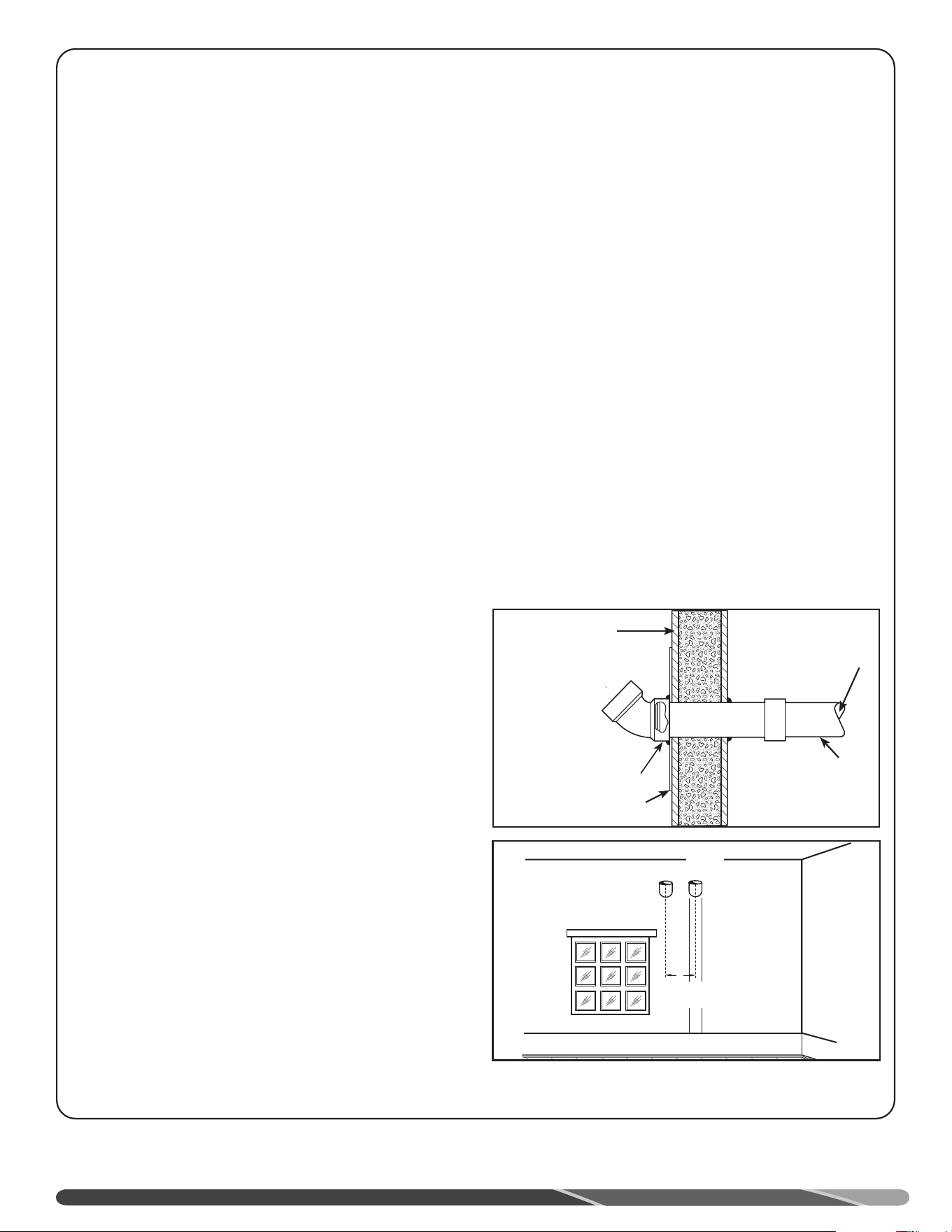
18
Min. 24 po (610 mm)
Apport Évac.
Considérations additionnelles (pages suivantes).
NE PAS positionner les terminaisons de ventilation sous un
porche ou une terrasse.
Afin de prévenir la condensation et le givrage de l’humidité
sur les murs ou sous la corniche du toit, NE PAS positionner
la terminaison d’évacuation sur un mur orienté vers les vents
dominants.
NE PAS positionner une terminaison de ventilation directement
sur un mur de briques ou de maçonnerie; le cas échéant, il
est recommandé d’installer un solin métallique résistant à la
corrosion à l’arrière de la terminaison (voir figure ci-dessus).
NE PAS positionner la terminaison trop près d’arbustes; les gaz
de combustion peuvent les endommager.
Étanchéifiez toutes les fentes, joints et jonctions dans un rayon de
6 pi
(1,83 m) autour de la terminaison.
Il est suggéré d’appliquer un apprêt à toutes les surfaces peintes,
afin de minimiser les risques de dommages. Les surfaces peintes
doivent être régulièrement entretenues.
INSTALLATION-TYPE, VENTILATION HORIZONTALE
Conduit et
manchon
Solin métallique sur mur de
brique ou de maçonnerie
Extérieur du
mur du bâtiment
Vers chauffe-eau
Conduit d’éva-
cuation
Terminaison
d’apport d’air avec
grille 1/2 po
insérée
Conduit
d’évacuation
Coude à au plus 1 po (25
mm) du mur
Assurez-vous que tous les conduits exposés au gel (grenier,
vide sanitaire, etc.) sont correctement supportés et possèdent
une pente appropriée, afin d’éviter toute accumulation de
condensation. NOTE: il est interdit d’isoler des conduits non
métalliques.
Ce chauffe-eau nécessite son propre système de ventilation
distinct.NE PAS raccorder le conduit d’évacuation à un autre
système existant ou à une cheminée.
L’humidité contenue dans les gaz de combustion peut se
condenser lorsqu’elle s’échappe de la terminaison de ventilation.
Par temps froid, cette condensation peut givrer et s’accumuler
sur un mur extérieur, sous la corniche du toit ou sur toute
surface adjacente. Prévoyez une certaine décoloration de
l’extérieur du bâtiment; toutefois, un positionnement inapproprié
de la terminaison ou sa mauvaise installation risque de
sérieusement endommager la finition extérieure ou même la
structure du bâtiment. Dans les lieux où il est habituel que la
température descende sous les 4°C (40°F) pendant de longues
périodes de temps, où dans une installation où la terminaison
d’évacuation fait face aux vents dominants, positionnez la
terminaison d’évacuation à au moins 2 pi (0,61 m) de toute
structure pouvant être endommagée par la condensation.
VENTILATION
À L’HORIZONTALE
Déterminez l’emplacement des terminaisons puis percez des
ouvertures permettant le passage du conduit d’évacuation à
travers le mur. Dans une installation murale, les conduits de
ventilation peuvent uniquement être orientés à l’horizontale (voir
figure Installation-type, ventilation horizontale).
Insérez une faible longueur du conduit d’évacuation à
travers le mur et connectez-le au raccord, comme dans la
figure Installation-type, ventilation horizontale. Connectez la
terminaison du conduit de ventilation à l’extérieur du bâtiment.
Étanchéifiez toute ouverture autour du conduit ou des raccords à
l’aide de mortier ou de scellant à la silicone, comme illustré à la
figure Installation-type, ventilation horizontale.
Complétez l’installation des conduits de ventilation aux raccords
du chauffe-eau. Au besoin, supportez toute section horizontale
comme précédemment indiqué.
INSTALLATION

17
INSTALLATION
Installation à ventilation directe (DV)
Assurez-vous que les gaz de combustion NE SERONT PAS
réaspirés par la terminaison d’apport d’air. Le rendement du
chauffe-eau peut être notablement affecté par la recirculation
des gaz de combustion.
Même si toutes les distances de dégagement entre les
terminaisons sont respectées, il peut y avoir recirculation des
gaz de combustion, en fonction notamment du positionnement
sur le bâtiment, la proximité d’autres bâtiments ou d’un coin,
les conditions météo, le vent ou la neige.
Assurez-vous régulièrement de l’absence de recirculation
des gaz de combustion. Certains indices signalent l’existence
d’une recirculation: terminaisons d’apport d’air givrée ou gelée,
condensation dans la terminaison et le conduit d’apport d’air,
rouille ou dépôt crayeux blanc sur le détecteur de flammes
ou le déflecteur de l’allumeur. Pour corriger un problème de
recirculation, il faut parfois réorienter la terminaison d’apport
d’air dans un axe différent de celui de l’évacuation, éloigner les
terminaisons l’une de l’autre ou tirer l’air frais de l’intérieur du
bâtiment. Assurez-vous que les terminaisons d’apport d’air et
d’évacuation ne sont pas obstruées, particulièrement lorsque la
température descend sous le point de congélation.
Toutes les composantes des conduits d’apport d’air et
d’évacuation doivent être du même diamètre. NE PAS utiliser
des conduits d’apport d’air et d’évacuation de diamètres
dissemblables.
Assurez-vous que toute condensation puisse s’évacuer
vers un drain de capacité suffisante, afin d’éviter toute
accumulation d’eau dans le chauffe-eau. Dans les climats
froids, prenez les précautions nécessaires pour éviter le gel
du tuyau d’évacuation de la condensation. Assurez-vous que
le collecteur de condensation ou la boucle de la conduite
d’évacuation de la condensation ne laissent pas s’échapper des
gaz de condensation. Reportez-vous à la section “Ventilation”
(page 8) du présent manuel pour les instructions complètes sur
la ventilation et l’évacuation de la condensation.
Une installation inadéquate des conduits et raccords de
ventilation peut engendrer un stress mécanique important
dans ceux-ci. Le recours à des brides de fixation rigides
ou à des supports qui empêchent le libre déplacement des
conduits de ventilation risque d’engendrer des contraintes
mécaniques élevées lors de la traversée d’un mur ou lors des
cycles d’expansion / contraction du conduit. Installez le conduit
de façon à minimiser ces contraintes mécaniques. Suivez la
procédure qui suit pour le perçage d’un orifice de pénétration
de conduits de ventilation à travers un mur:
1. Découpez deux orifices pour le passage des conduits. Prévoir
un diamètre de 2,5 po (64 mm) pour un conduit de 2 po, 3,5
po (89 mm) pour un conduit de 3 po et de 6,5 po (165 mm)
pour un conduit de 6 po. Prévoir un dégagement horizontal
d’au moins 24 (610 mm) entre les terminaisons.
2. Utilisez un système d’adhésion approprié pour PVC (apprêt
et adhésif) pour raccorder les terminaisons d’apport d’air et
d’évacuation fournis aux conduits de ventilation. La distance
entre la partie arrière de la terminaison d’évacuation et le
mur extérieur doit être supérieure d’au moins 6 po (127 mm)
à celle entre la terminaison d’évacuation et la terminaison
d’apport d’air. Utiliser un adhésif ou un produit d’étanchéité,
ainsi qu’une méthode d’assemblage appropriés pour le
raccordement des conduits de ventilation au ventilateur.
Tout tronçon horizontal de conduit d’apport d’air doit être
supporté au moins tous les 3 pi (914 mm).
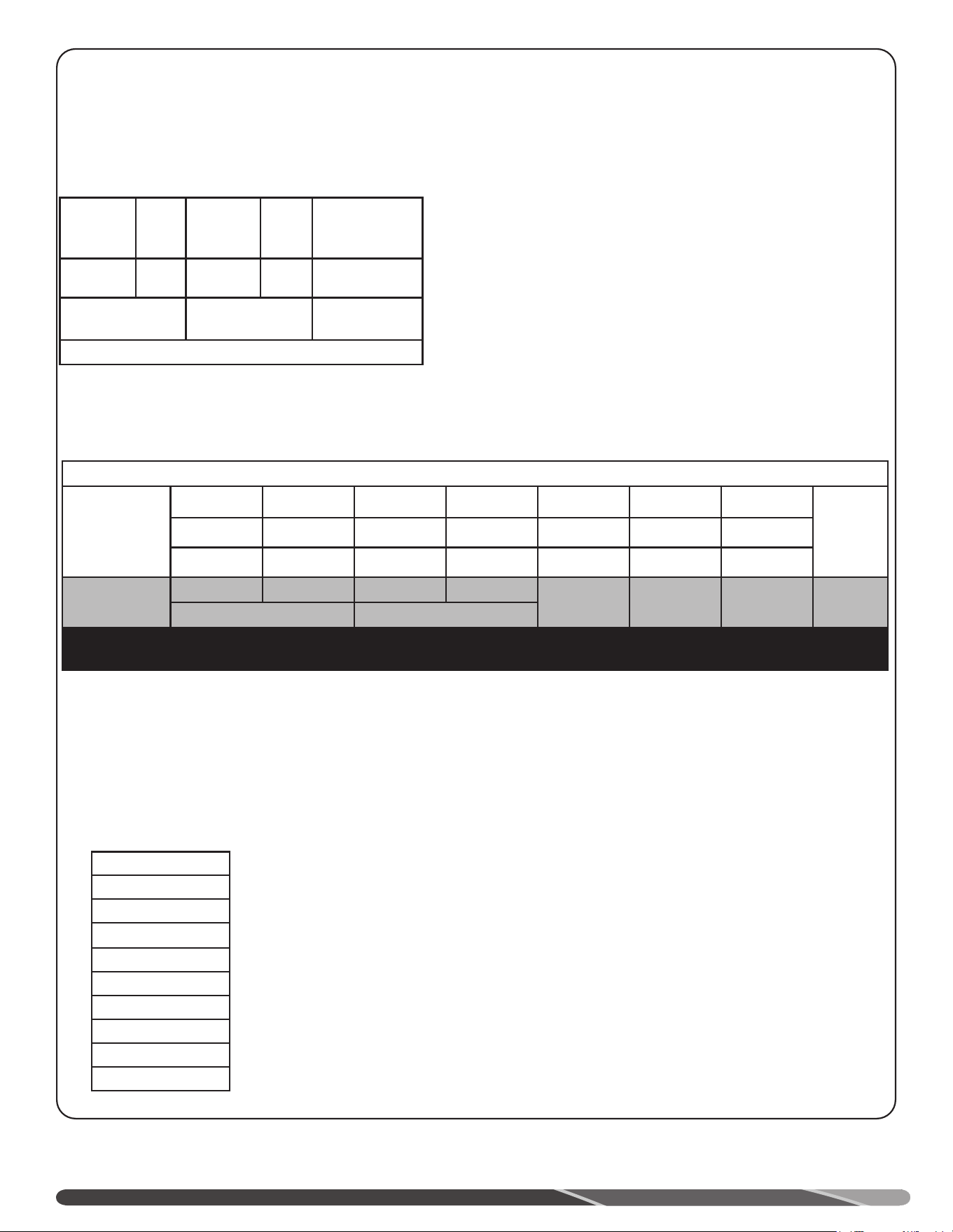
16
INSTALLATION
NOTE: raccords d’apport d’air et d’évacuation femelle, pour tuyau 2 po, Schedule 40. Il est possible d’utiliser un adaptateur pour utiliser
un tuyau 3 po ou 4 po (conduits d’apport d’air et d’évacuation). Les conduits d’apport d’air et d’évacuation doivent toujours être de taille
identique. Les calculs de longueur équivalente doivent être basés sur le diamètre de la terminaison.
Suivez les directives d’installation du fabricant des tuyaux
flexibles.
Tous les modèles à évacuation directe et forcée (PDV) peuvent utiliser
un système de ventilation concentrique de 2 po pour les longueurs
ci-dessus.
Les terminaisons concentriques de 2 po nécessitent des conduits rigides
de 2 po.
NE PAS utiliser des diamètres de conduits rigides autres que ceux
indiqués pour chaque diamètre de terminaison concentrique; cela
peut causer un dysfonctionnement du chauffe-eau ou entraîner son
verrouillage.
Les terminaisons concentriques de 3 po peuvent être raccordées à des
conduits de 3 ou 4 po.
Tuyau en polypropylène flexible (pi)
Diamètre
conduit (po)
2" 3"
Apport
d’air
Évacuation
Apport
d"air
Évacuation
Long. max.
évac. forcée
(PV)
0 30’ (13m) 0 30’ (13m)
Longueur minimale et maximale
de ventilation
Informations importantes pour toutes les installations:
1) Les longueurs minimales requises correspondent à la longueur des conduits d’apport d’air et
d’évacuation, entre le chauffe-eau et l’extérieur du bâtiment.
2) Chaque coude à 90° (à rayon standard ou long) possède une
longueur équivalente comme indiqué.
3) Chaque coude à 45° possède une longueur équivalente de 2,5 pi (0,76 m).
4) NE PAS utiliser des sections de conduits de diamètre différent; les conduits doivent être de diamètre
uniforme sur toute leur longueur.
5) Les terminaisons de ventilation (horizontales ou verticales) doivent être positionnées à au moins 24 po
(610 mm) et à au plus 36 po (914 mm) l’une de l’autre (centre-à-centre).
Le dépassement de la longueur équivalente maximale peut causer un mauvais fonctionnement du chauffe-
eau ou son verrouillage.
pieds à mètres
20 6,1
50 15,2
60 18,3
70 21,3
80 24,4
100 30,5
120 36,6
130 39,6
170 51,8
Longueurs ventilation équivalent commercial
50G-76K et 50G-100K; ÉVAC. FORCÉE
(PV); (CONDUIT RIGIDE)
50G-76K et 50G-100K; ÉVAC. DIR. ET FORCÉE
(PDV); (CONDUIT RIGIDE)
Altitude
pi
Diamètre
(po)
Long. éq. max.
GN (pi)
Long. éq. max.
PL (pi)
Long. éq. max. GN (pi) Long. éq. max. PL (pi)
Terminaisons
Apport d’air Évacuation Apport d"air Évacuation
0-10 100
2" 40’ 40’ 40’ 40’ 40’ 40’
COUDES
90° 2" et 3";
CONCENTRIQUE
2", 3" et 4"; et
TERMINAISON
2"et 3"
3" 140’ 140’ 140’ 140’ 140’ 140’
4" 140’ 140’ 140’ 140’ 140’ 140’
LONGUEUR MINIMALE DES CONDUITS D’APPORT D’AIR ET D’ÉVACUATION: 10 PI ÉQ.
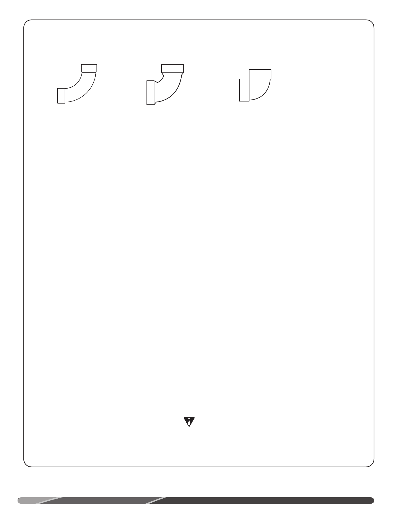
15
INSTALLATION
Tous les joints du système de ventilation doivent être étanches;
nous recommandons les produits suivants:
Composantes en PVC: adhésif de type ASTM D-2564;
Composantes en PVC: adhésif de type ASTM F-493;
Composantes en ABS: adhésif de type ASTM D-2235
(ABS non permis au Canada).
Apprêt-nettoyant et adhésif de consistance moyenne
1. Coupez les tuyaux à angle droit et ébarbez les imperfections
laissées par la coupe. Réalisez un chanfrein d’introduction
à l’extrémité du tuyau; nettoyez l’extrémité du tuyau et
l’emboîture du raccord.
2. Après avoir vérifié le bon ajustement du tuyau et du raccord,
appliquez une couche généreuse d’apprêt-nettoyant sur la
surface extérieure du tuyau et à l’intérieur du raccord. NE
PAS laisser l’apprêt sécher avant d’appliquer l’adhésif.
3. Appliquez une mince couche d’adhésif dans le raccord.
Appliquez rapidement une généreuse couche d’adhésif sur
l’extrémité du tuyau. Insérez-le avec une légère rotation,
jusqu’à ce qu’il bute au fond du raccord.
AVIS:
L’adhésif doit être fluide; s’il a durci, en réappliquer.
4. Maintenez en place le joint pendant environ 30 secondes; il
arrive parfois que le tuyau soit expulsé du raccord lors du
durcissement.
5. Nettoyez tout excès d’adhésif à l’aide d’un chiffon. Laissez
le joint durcir pendant 15 minutes avant de la manipuler. La
durée de durcissement varie en fonction de l’ajustement du
joint, de la température et de l’humidité.
AVIS:
Agitez fréquemment l’adhésif lorsque le pot est en
utilisation. Utilisez une brosse à soies naturelles ou
l’applicateur fourni avec le pot de colle. Utilisez une brosse
d’un pouce (25 mm), le cas échéant.
POUR UNE BONNE
INSTALLATION
ATTENTION:
• NE PAS utiliser de colle caillée, grumeleuse ou
épaissie.
• NE PAS délayer l’adhésif. Respectez la date
d’expiration indiquée sur le pot.
• Pour un assemblage à une température inférieure
à 0°C (32°F), utilisez uniquement un adhésif basse
température.
• Utilisez toujours l’apprêt-nettoyant et l’adhésif conçus
précisément pour le type de tuyau utilisé (PVC, CPVC,
PP ou ABS).
DANGER D’INCENDIE
OU DE BLESSURE
Les apprêts et adhésifs à base de solvants sont très
inflammables. Travaillez dans un lieu bien ventilé et ne pas
assembler à proximité de toute source de chaleur ou flamme
nue. NE PAS fumer. Évitez tout contact avec la peau ou les
yeux. Respectez tous les avertissements imprimés sur les
contenants.
Considérations additionnelles, coudes
Longueur équiv.
10 pieds
Longueur équiv.
8 pieds
Longueur équiv.
5 pieds
Coude à 90°
à faible rayon
Coude à 90°
standard
Coude à 90°
à long rayon
EXEMPLES DE COUDES:
Il est recommandé
d’uniquement utiliser
des coudes à rayon de
courbure standard ou
allongé. Voir exemples
illustrés.
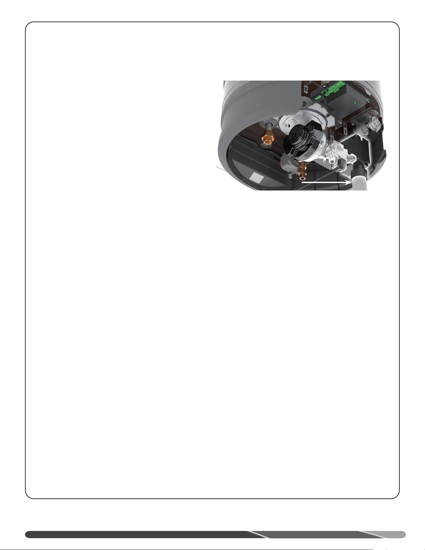
14
AVIS:
L’utilisation de conduits à âme alvéolaire en PVC (ASTM-F891),
en ABS de calibre 40 (Schedule 40), DWV à âme alvéolaire
(ASTM-F628) ou en RadelMD (polyphenylsulfone) dans un
système de ventilation non métallique, est interdite.
La ventilation peut être à configuration horizontale (terminaison
à travers un mur) ou verticale (terminaison à travers le toit).
Les sections de conduits verticaux et horizontaux doivent être
adéquatement supportées. L’intervalle maximal recommandé entre
les sangles est de 3 pi (0,915 m). Installez la première sangle au
début de la première section horizontale, immédiatement à la suite
du premier coude à 90° qui réoriente le conduit de la verticale
à l’horizontale. Afin de réduire la transmission de vibrations
aux solives du plancher ou à toute autre structure de soutien,
il est recommandé d’installer des coussinets isolants entre les
sangles de support et le conduit. NE PAS supporter le système
de ventilation de façon à restreindre les mouvements normaux
d’expansion et de contraction thermique du matériau choisi (les
appuis doivent être libres).
Si le chauffe-eau est installé comme appareil de remplacement
d’un autre chauffe-eau à évacuation forcée (PV) ou à évacuation
directe et forcée (PDV), procédez à une inspection minutieuse du
système d’évacuation existant avant d’entreprendre l’installation.
Assurez-vous qu’il est fabriqué de matériaux adéquats, comme
décrit plus haut, que sa longueur équivalente corresponde aux
limites minimales et maximales prescrites et que sa terminaison
est installée comme décrit dans le présent manuel. Inspectez
attentivement tout le système de ventilation, portez une attention
particulière à l’éventuelle présence de fissures et de fractures,
particulièrement dans les joints des coudes, des divers raccords et
des sections linéaires. Assurez-vous de l’absence d’affaissement
ou de tout autre signe de contrainte dans les joints, notamment
en raison d’un mauvais alignement des composants du système.
Toute anomalie doit être corrigée conformément aux instructions
de ventilation du présent manuel, avant de terminer les travaux
d’installation et de mettre en service le chauffe-eau.
Des informations supplémentaires sur l’installation dans le
Commonwealth of Massachusetts se trouvent à l’arrière du
manuel.
INSTALLATION
RACCORD D’APPORT
D’AIR
Reportez-vous à la figure "Raccordement d’apport d’air", pour
effectuer le raccordement d’apport d’air au chauffe-eau. Ces
modèles peuvent être ventilés par ventilation directe (DV) ou
par évacuation forcée (PV).
AVIS:
Dans une installation à évacuation forcée (PV), la grille de
terminaison doit être installée sur le conduit d’apport d’air.
Avant même d’entreprendre l’installation, planifiez
l’acheminement du système de ventilation avec une grande
attention. Minimisez la longueur des conduits de ventilation
(apport d’air et évacuation). Reportez-vous au Tableau 1, pour
le dimensionnement des conduits de ventilation (diamètre,
longueur équivalente totale). NE PAS dépasser les longueurs
équivalentes admissibles indiquées dans les tableaux.
En fonction du diamètre sélectionné pour le système de
ventilation, il peut être nécessaire d’installer un raccord
adaptateur de diamètre au raccord du chauffe-eau. NE PAS
réduire le diamètre à moins de 2 po. Tous les modèles sont
livrés avec des terminaisons de ventilation de 2 po avec
grille intégrée. Le diamètre des terminaisons doit toujours
être identique au diamètre des conduits du système de
ventilation.
Dans une installation à ventilation directe (DV) horizontale
(murale), les deux terminaisons doivent être positionnées à
l’horizontale sur le même mur extérieur, avec un entre-axes
d’au moins 15 po (380 mm).
RACCORDEMENT DES
CONDUITS ET RAC-
CORDS
Tous les tuyaux, raccords, apprêts, adhésifs et procédures
doivent se conformer aux normes de l’«American National
Standards Institute» et de l’«American Society for Testing
and Materials» (ANSI/ASTM) aux États-Unis. Au Canada,
les tuyaux, raccords, adhésifs, apprêts et procédures de
raccordement doivent être conformes à la norme ULC-S636 et
aux exigences du fabricant du système de ventilation.
COLLAGE DES JOINTS
AVIS:
Tous les tuyaux, raccords, apprêts, adhésifs et procédures
doivent se conformer aux normes de l’«American National
Standards Institute» et de l’«American Society for Testing
and Materials» (ANSI/ASTM).
Raccord d’apport d’air
ventilateur
Réducteur
de bruit
RACCORDEMENT D’APPORT D’AIR
13
INSTALLATION
APPORT D’AIR ET ÉVACUATION
NOTE: cet appareil peut uniquement être ventilé par ventilation
directe (DV) ou par évacuation forcée (PV).
NOTE: Installations à évacuation forcée: Cat. IV.
!
AVERTISSEMENT:
NE PAS raccorder ce chauffe-eau à tout conduit d’évacuation
existant ou à une cheminée; il doit être ventilé séparément
de tout autre appareil, à l’aide de conduits de ventilation
approuvés.
!
AVERTISSEMENT:
Le défaut de ventiler le chauffe-eau à l’extérieur du bâtiment
comme indiqué ci-dessus et dans la section qui suit peut
entraîner son mauvais fonctionnement, ce qui peut causer
un incendie ou une explosion pouvant se traduire par des
dommages matériels, de graves blessures ou la mort.
!
DANGER:
Afin d’éviter un risque d’incendie, d’explosion ou d’asphyxie
des occupants au monoxyde de carbone, ne faites JAMAIS
fonctionner le chauffe-eau si ses conduits d’apport d’air et
d’évacuation ne sont pas installés en conformité avec les
directives de la présente section.
Les sections successives des conduits d’apport d’air et
d’évacuation doivent se chevaucher d’au moins 1/2 po
(13 mm) à chaque joint. Il est important que les sections
de conduits d’apport d’air et d’évacuation s’emboîtent
correctement aux raccords jusqu’à la cure complète de
l’adhésif. NE PAS percer de trous dans les conduits de
plastique ou leurs raccords.
IMPORTANT
Lorsque les codes d’état ou codes locaux applicables
exigent l’installation de terminaisons, qui dans le présent
Manuel d’utilisation et d’entretien doivent être certifiés
conformément à la norme UL 1738 pour les systèmes
de ventilation des appareils de combustion au gaz de
Catégories II, III et IV, veuillez communiquer avec le Service
technique du fabricant (voir la dernière page).
AVIS:
Cet appareil peut uniquement être ventilé avec des conduits
fabriqués des matériaux indiqués ci-dessous.
Utilisez uniquement des conduits de 2, 3 ou 4 po de
diamètre.
Reportez-vous à vos codes locaux pour connaître les
exigences d’utilisation des conduits et raccords en PVC, en
CPVC, en PP ou en ABS. Au Canada, tous les composants
entrant dans la fabrication du système de ventilation doivent
être homologués ULC-S636.
NOTE: Dans l’état du Massachusetts, utilisez uniquement
des tuyaux, raccords et terminaisons en plastique tels que
spécifiés dans le présent manuel et qui sont approuvés par
le Massachusetts Board of State Examiners of Plumbers and
Gas pour l’évacuation d’appareils à combustion (voir lien
ci-dessous):
https://licensing.reg.state.ma.us/pubLic/pl_products/
pb_pre_form.asp
PVC (DWV, ASTM-D2665 ou CSA B181.2)
PVC (Schedule 40, ASTM-D1785 ou CSA B137.3)
PVC (SDR Series, ASTM-D2241 ou CSA B137.3)
CPVC (CPVC 4120, ASTM-D2846 ou CSA B137.6)
CPVC (Schedule 40, ASTM-F441 ou CSA B137.3)
CPVC (SDR Series, ASTM-F442)
ABS (Schedule 40, DWV, ASTM-D2661 ou CSA B181.1)
ABS (annexe 40, DWV, noyau cellulaire, ASTM-F628)
Polypropylène
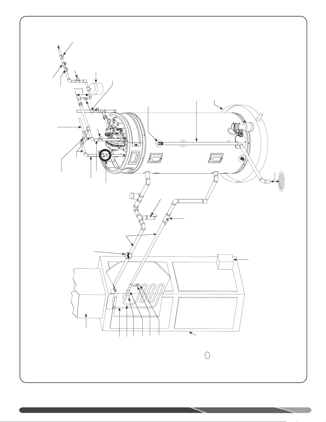
Clapet anti-
retour 3/4 po
avec reniflard de
1/8 po
Manomètre
Conduite d’eau chaude
Alimentation en eau froide
Robinet d’arrêt
3/4 po
Alimentation en gaz
Alimentation
en eau froide
Piège à chaleur
6” min.
Robinet d’arrêt
3/4 po
Réservoir d’expansion de 2
USG (7,6 L) (si requis, non
fourni)
Robinet
d’arrêt
3/4 po
3/4 po Eau chaude
potable tempérée
vers la maison.
Longueur d’au moins 24 po (610 mm)
de tuyau de cuivre 3/4 po de type L,
depuis les raccords du chauffe-eau.
Installation d’une vanne thermostatique
de 3/4 po (lire avertissement ci-dessus).
Suivez les directives d’installation du
fabricant du robinet mélangeur ou de
la vanne thermostatique.
Robinet d’isolation entre le
chauffe-eau et l’appareil de
chauffage, eau chaude (non fourni)
Voir diagramme au haut de la page
(conduite d’eau chaude verticale vs
horizontale).
Soupape de sûreté T&P (installée
selon les codes locaux)
Soupape de sûreté T&P et
tuyau de décharge
60°C (140°F)
49°C (120°F) à
54°C (130°F)
Le chauffe-eau est installé dans un
bac d’égouttement, conformément
à la réglementation locale ou aux
codes locaux.
Hauteur libre, 6 po
Robinet d’isolation
entre le chauffe-
eau et l’appareil
de chauffage, eau
froide (non fourni)
Robinet de
vidange
(non fourni avec
le chauffe-eau)
Coupe-vide
Conduites
alimentation
et retour de
l’échangeur.
Le chauffe-eau est installé
dans un bac d’égouttement,
conformément à la
réglementation locale ou aux
codes locaux.
Ventilo-
convecteur
T
FAN
ON
OFF
HEAT
COOL
Vers thermostat central.
La boucle de chauffage
entre le chauffe-eau et
l’échangeur de chaleur
doit être composée de
tuyau FlowGuard Gold
en CPVC ou l’équivalent
Eau chaude
vers échangeur
Serpentin/échangeur
Pompe à corps
en bronze
Clapet de non-retour
dans la pompe
Purgeur d’air
Robinet
d’échantillonnage
Régulateur de
débit
12
DIAGRAMME DE PLOMBERIE-TYPE, CHAUFFAGE COMBINÉ
INSTALLATION
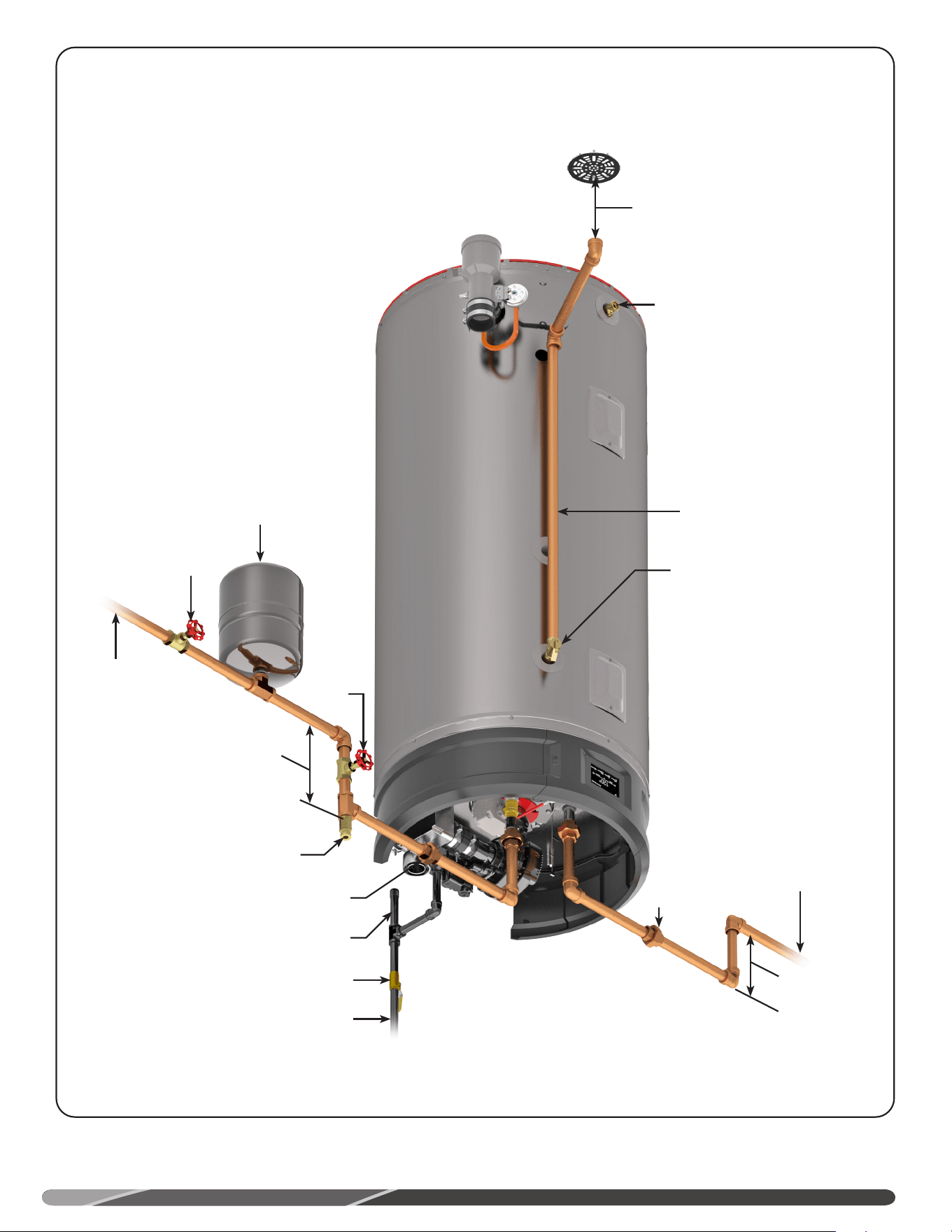
11
Alimentation en gaz
Robinet d’arrêt manuel du gaz
Robinet de vidange
Raccord-union
Raccord-union
Réservoir d’expansion
thermique (non fourni)
Si requis, installer en conformité aux
codes locaux et aux directives du
fabricant du réservoir.
Alimentation
en eau
froide
Brise-vide (non fourni)
Si requis, installer en conformité aux
codes locaux et aux directives du
fabricant du brise-vide.
Piège à chaleur
6 po min.
Piège à chaleur
6 po min.
Robinet
d’arrêt
Robinet
d’arrêt
Collecteur de sédiments
Soupape de sûreté température
et pression (T&P)
Tuyau de décharge
vers drain ouvert
approprié
Hauteur libre 150 mm (6 po)
NOTES:
Les conduites
d’alimentation en gaz du
chauffe-eau doivent être
adéquatement supportées
et alignées, afin de
minimiser le transfert de
contrainte à la commande
du gaz et au brûleur.
Eau chaude
vers appareils
INSTALLATION-TYPE
INSTALLATION
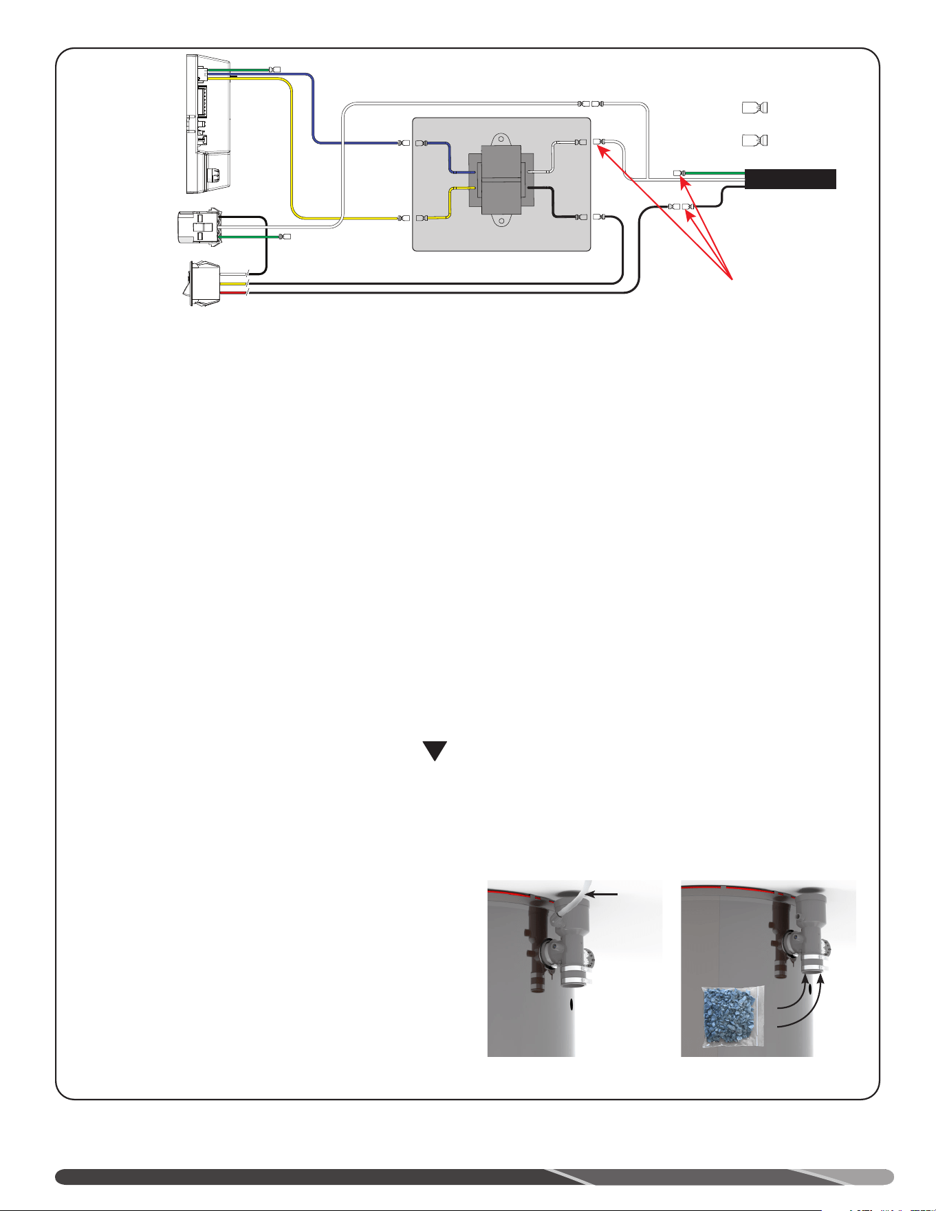
10
environ une tasse d’eau dans le té d’évacuation.
Comme ce chauffe-eau génère de la condensation, il doit être
installé à proximité d’un drain de capacité suffisante. Le tuyau
de drainage de la condensation et ses raccords doivent être
installés selon les instructions d’installation.
Assurez-vous que la condensation s’écoule librement jusqu’au
drain et ne s’accumule pas dans le collecteur de condensation
ou dans le tuyau d’évacuation de la condensation. Dans les
climats froids, prenez les précautions nécessaires pour éviter le
gel du tuyau de drainage de la condensation, p. ex.: le recouvrir
de ruban chauffant étanche à l’eau.
• La condensation est légèrement acide et doit être recueillie
et éliminée selon les exigences des codes locaux, certains
exigeant sa neutralisation avant son renvoi au drain. Ce
chauffe-eau est livré avec un sac de produit neutralisant.
Versez le neutralisant dans le té d’évacuation avant d’installer
le conduit d’évacuation. Assurez-vous que le neutralisant
s’est déposé au fond du té d’évacuation.
• Utilisez uniquement des tubes en PVC, CPVC ou en boyau
flexible pour évacuer la condensation. Si un boyau flexible
est utilisé: s’assurer qu’il ne soit pas courbé ou tordu et qu’il
maintient une pente uniforme jusqu’au drain.
• Le diamètre du tuyau de drainage doit être égal ou supérieur
à celui du raccord de collecte de la condensation (1/2 po).
• Le tuyau de drainage doit être aussi court que possible et
maintenir une pente descendante jusqu’à son extrémité; à
défaut, celui-ci pourrait se bloquer, ce qui entraînera un
mauvais fonctionnement du chauffe-eau. Si une pente
descendante ne peut être maintenue, installez une pompe
à condensation pour acheminer la condensation jusqu’à un
drain approprié.
• L’extrémité du tuyau de drainage doit être à l’air libre, elle ne
doit pas se terminer sous l’eau.
• NE PAS directement raccorder le tuyau de drainage à un
égout.
• NE PAS connecte le tuyau de drainage à celui de tout autre
appareil.
• NE DOIT PAS se décharger dans le bac d’égouttement.
• NE PAS décharger la condensation sur un passage public, un
trottoir ou à tout endroit où le gel de la condensation pourrait
produire une surface glissante sur laquelle une chute pourrait
causer des blessures.
HAUTE ALTITUDE
La puissance nominale du chauffe-eau est basée sur une
utilisation au niveau de la mer. À une altitude plus élevée, la
puissance produite peut être inférieure que la valeur indiquée
sur la plaque signalétique en raison de la pression intérieure de
gaz naturel ou de propane.
!
AVERTISSEMENT:
Le défaut d’installer un chauffe-eau réglé pour l’altitude
du lieu d’installation peut endommager et causer le
dysfonctionnement de l’appareil, ce qui peut entraîner un
échappement de monoxyde de carbone pouvant se traduire
par de graves blessures ou la mort.
CÂBLAGE
Circuit de dérivation 120 V, 50/60 Hz, correctement polarisé,
avec dispositif de sectionnement approprié. Cet appareil
nécessite un courant maximal de 7 A. Avant d’être mis en
service, l’appareil doit être mis à la masse en conformité
avec les codes locaux ou, en l’absence de codes locaux, en
conformité avec le « National Electrical Code, ANSI/NFPA
70 » aux États-Unis, ou le « Code canadien de l’électricité
CSA C22.1 » au Canada. Une mauvaise mise à la masse ou
l’inversion de la polarité peut entraîner le dysfonctionnement
de chauffée-eau.
INSTALLATION
CONDENSATION
NEUTRALISANT
DRAIN DE
CONDENSATION
Vers drain
ouvert
Transformateur
(120V / 60Hz)
F
F
F
F
M
M
M
M
F
Au bloc de ferme
Au bloc de ferme
Au bloc de ferme
Au bloc de ferme
Au bloc de ferme
Au bloc de ferme
3
2
1
3
2
1
3
2
1
F
F
F
M
F
M
Cordon d'alimentation
Commutateur d'achage
sur l'écran avant
C1
Ventilateur
Câble d'alimentation
C2
Commande de l’allumage
Câble d'alimentation
C3
Commutateur d'achage
sur l'écran avant
C1
Ventilateur
Câble d'alimentation
C2
Commande de l’allumage
Câble d'alimentation
C3
M
F
2-520263-2
déconnecter
2-520102-2
déconnecter
M
F
2-520263-2
déconnecter
2-520102-2
déconnecter
F
F
F
F
M
M
M
M
F
3
2
1
3
2
1
3
2
1
F
F
F
M
F
M
Les sectionneurs peuvent être retirés et leurs
câbles raccordés, avec un capuchon de connexion,
au câble d’alimentation de la boîte de jonction si
nécessaire.
Cordon d'alimentation
Transformateur
(120V / 60Hz)
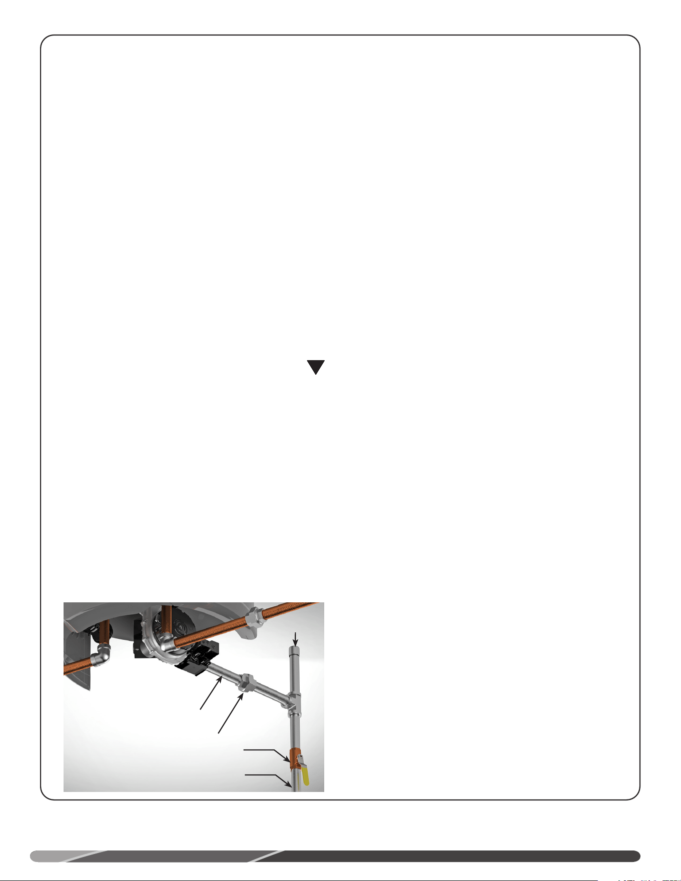
9
décharge ne doit comporter aucune robinetterie ou restriction,
ni aucun raccord réducteur.
REMPLISSAGE DU CHAUFFE-EAU
Assurez-vous que le robinet de vidange du chauffe-eau
est fermé, puis ouvrez le robinet d’arrêt de la conduite
d’alimentation en eau froide.
Ouvrez tous les robinets d’eau chaude de la résidence
afin de purger l’air emprisonné dans le chauffe-eau et les
canalisations.
L’obtention d’un jet d’eau continu de tous les robinets d’eau
chaude indique que le chauffe-eau est complètement rempli
d’eau.
ALIMENTATION EN GAZ
La pression d’alimentation en gaz du chauffe-eau ne doit
PAS excéder 10,5 po c.e. (2,6 kPa) pour le gaz naturel et 13
po c.e. (3,2 kPa) pour le propane. La plaque signalétique du
chauffe-eau indique la pression minimale d’alimentation
requise lorsque le brûleur est allumé. Assurez-vous que
la canalisation d’alimentation en gaz n’est pas sous- ou
surpressurisée; appelez le fournisseur de gaz le cas échéant.
La conduite d’alimentation en gaz du chauffe-eau doit être
correctement dimensionnée, nettoyée et fabriquée en acier ou
de tout autre matériau approuvé.
La conduite d’alimentation en gaz doit comporter un raccord-
union à proximité du chauffe-eau ou le raccordement doit être
effectué à l’aide d’un conduit de raccordement flexible certifié
par ANSI. Aux États-Unis, le National Fuel Gas Code exige
l’installation d’un robinet d’arrêt manuel du gaz; le consulter
pour plus de détails.
Si un conduit de raccordement flexible est utilisé, sa
longueur doit être inférieure à 914 mm (36 po) et il doit être
conforme aux exigences de la norme ANSI Z21.24/CSA 6.10 -
Connectors for gas appliances.
Pour les appareils au propane, le composé d’étanchéité
utilisé sur les filets des conduites doit être certifié pour une
utilisation avec du propane. Appliquez une mince couche de
composé uniquement sur les raccords mâles.
Lorsque l’appareil ne comporte pas de collecteur de
sédiments intégré, installez un collecteur de sédiments
en aval du robinet d’arrêt manuel de l’appareil, aussi près
que possible du point d’entrée du gaz dans l’appareil. Le
collecteur de sédiments doit être fabriqué à l’aide d’un té
dont l’orifice inférieur est capuchonné, ou il peut s’agir d’un
dispositif conçu précisément pour recueillir les impuretés.
Voir figure.
NE PAS utiliser une force excessive (20 lb-pi) pour serrant le
joint de tuyau à l’entrée de la commande du gaz (thermostat),
en particulier si les filets sont étanchéifiés avec du Teflon, au
risque d’endommager le boîtier de la commande du gaz.
La plaque signalétique du chauffe-eau indique la pression
minimale d’alimentation requise lorsque le brûleur est
allumé. Si la conduite d’alimentation en gaz est sous- ou
surpressurisée, veuillez joindre le fournisseur de service du
gaz pour qu’il corrige la situation.
INSTALLATION
Il est recommandé d’installer un raccord-union et un robinet
d’arrêt manuel sur la canalisation d’alimentation en gaz du
chauffe-eau, à proximité de celui-ci, afin de faciliter le retrait
de l’assemblage du brûleur. Le robinet d’arrêt manuel doit
être placé à portée de main.
ESSAI D’ÉTANCHÉITÉ
Le chauffe-eau et tous ses raccords doivent subir un essai
d’étanchéité à la pression de service normale, avant la mise
en service du chauffe-eau. Ouvrez le robinet d’arrêt manuel
du gaz situé à proximité du chauffe-eau. Appliquez une
solution savonneuse pour vérifier l’étanchéité de tous les
raccords. La présence de bulles indique la présence d’une
fuite. Toute fuite doit être colmatée. L’étanchéité des raccords
de la commande du gaz effectués en usine doit aussi être
vérifiée lorsque le chauffe-eau fonctionne.
!
AVERTISSEMENT:
N’utilisez JAMAIS une flamme nue pour effectuer un
essai d’étanchéité; cela pourrait entraîner des dommages
matériels, de graves blessures ou la mort.
ESSAI DE PRESSION DU SYSTÈME D’ALIMENTATION EN GAZ
Le chauffe-eau et son robinet d’arrêt manuel DOIVENT être
déconnectés du réseau d’alimentation en gaz lors de tout
essai d’étanchéité effectué à une pression supérieure à 1/2
psi (3,5 kPa).
Lorsque l’essai d’étanchéité est effectué à une pression
de 1/2 psi (14 po c.e. / 3,5 kPa) ou moins, le chauffe-eau
peut être isolé du réseau d’alimentation en gaz par la seule
fermeture du robinet d’arrêt manuel du gaz.
CONDENSATION
Le té d’évacuation/collecteur de condensation est monté
au chauffe-eau à l’usine. Versez le neutralisant dans le
té d’évacuation avant d’installer le conduit d’évacuation.
Assurez-vous que le neutralisant se trouve au fond du té,
comme illustré dans la figure de la page suivante.
Ce chauffe-eau est un appareil à haute efficacité énergétique
muni d’un dispositif d’évacuation de la condensation. Le
té d’évacuation/collecteur de condensation doit être rempli
d’eau avant la mise en service du chauffe-eau. Versez
Alimentation en gaz
Robinet d’arrêt manuel du gaz
Tuyau vers commande du gaz
Collecteur de
sédiments
Raccord-union

8
INSTALLATION
Si le chauffe-eau doit être installé sur une surface tapissée,
celle-ci doit être recouverte par un panneau de métal ou
de bois dont les dimensions surplombent la pleine largeur
et profondeur de l’appareil d’au moins 76 mm (3 po). Si ce
chauffe-eau est installé dans un placard ou une alcôve, la
totalité de la surface du plancher doit être recouverte par le
panneau de bois ou de métal.
ATMOSPHÈRE CORROSIVE
Par exemple, l’air des lieux suivants contient souvent des
hydrocarbures halogénés: salon de beauté, commerce de
nettoyage à sec, laboratoire de développement de photos,
lieux où sont entreposés des produits chlorés en poudre ou
liquides ou des produits pour la piscine.
De l’air contenant des hydrocarbures halogénés est salubre à
respirer, mais son passage à travers une flamme génère des
produits corrosifs qui raccourcissent la durée de vie de tout
appareil au gaz.
Le gaz propulseur des produits en canette ou le gaz libéré
par une fuite de climatiseur ou d’équipement de réfrigération
génère des produits hautement corrosifs à la suite de son
passage dans une flamme.
Toute défectuosité du chauffe-eau causée par une
atmosphère corrosive invalide sa garantie.
EXPANSION THERMIQUE
Déterminez si la conduite d’alimentation en eau froide
comporte un clapet antiretour. Il pourrait s’agir d’un clapet
installé séparément sur la conduite d’eau froide ou intégré
à un dispositif anti-retour, à un réducteur de pression, à
un compteur d’eau ou à un adoucisseur d’eau. Lorsqu’un
clapet antiretour est installé dans la conduite d’alimentation
en eau froide, on est en présence d’un "système fermé".
Inversement, lorsque la conduite d’alimentation en eau froide
n’est pas munie d’un dispositif antirefoulement, on est en
présence d’un système "ouvert".
Lorsque l’on chauffe de l’eau, celle-ci gagne en volume,
ce qui risque d’engendrer une hausse de pression dans le
système d’alimentation en eau. Ce phénomène se nomme
”expansion thermique”. Dans un système “ouvert”, le volume
supplémentaire d’eau engendré par le chauffage de l’eau
dans le chauffe-eau est refoulé vers la conduite maîtresse de
la municipalité, ce qui évite toute hausse de pression.
Toutefois, dans un système “fermé”, le volume
supplémentaire d’eau chaude ne peut se diriger vers la
canalisation maîtresse, ce qui peut entraîner une hausse
rapide et dangereuse de pression dans le chauffe-eau
(phénomène “d’expansion thermique”) et dans le réseau
d’eau de la résidence. La pression peut ainsi rapidement
atteindre la valeur de déclenchement de la soupape de sûreté,
ce qui entraîne un écoulement d’eau lors de chaque cycle de
chauffage de l’eau. Ce phénomène d’expansion thermique de
l’eau, qui entraîne des cycles d’expansion et de contraction
rapides des composantes du chauffe-eau et du réseau d’eau,
peut causer une défaillance prématurée de la soupape de
sûreté ou même du chauffe-eau. Le remplacement de la
soupape de sûreté ne permet pas de corriger ce problème!
Il est plutôt suggéré d’installer un réservoir d’expansion
thermique sur la conduite d’alimentation en eau froide, entre
le clapet antiretour et le chauffe-eau. Le réservoir d’expansion
renferme un volume d’air qui se comprime lorsque la
pression augmente dans le système. Cela permet de dissiper
la surpression et d’empêcher le déclenchement répété de
la soupape de sûreté. Il existe d’autres moyens de contrôle
de l’expansion thermique. Veuillez communiquer avec un
plombier, votre fournisseur du service d’eau ou un inspecteur en
plomberie pour obtenir plus de détails.
RACCORDS D’EAU
Reportez-vous à l’illustration de la page 12 (installation-type). Il
est recommandé d’installer des raccords union ou des tuyaux
de raccordement flexibles sur les conduits d’eau froide et
d’eau chaude du chauffe-eau, ce qui facilite le débranchement
du chauffe-eau du réseau, au besoin. Si des tuyaux de
raccordement flexibles sont installés, ils doivent être conformes
à la norme relative aux raccords flexibles, ASME A112.18.6/CSA-
B125.6. Les raccords d’eau chaude et d’eau froide du chauffe-
eau sont clairement identifiés (“HOT” et “COLD”). Installez un
robinet d’arrêt sur la conduite d’alimentation en eau froide, à
proximité du chauffe-eau.
IMPORTANT
Pour les modèles équipés de panneaux avant et latéraux: il
est recommandé que les conduites d’eau chaude et froide
s’élèvent sur une hauteur d’au moins 10 po (250 mm), depuis
la partie supérieure du chauffe-eau, avant leur premier
coude. Ce dégagement est requis pour permettre le retrait et
la réinstallation des panneaux latéraux.
Les panneaux latéraux doivent être enlevés pour accéder
aux raccords d’eau chaude et froide. Les panneaux latéraux
sont fixés sur le dessus du chauffe-eau avec des chevilles
de fixation (voir illustration). Tirez les panneaux latéraux vers
l’extérieur ou vers le haut pour les libérer des chevilles.
SOUPAPE DE SURPRESSION
La pression nominale de déclenchement de la soupape de sûreté
ne doit pas dépasser 150 psi (1034 kPa), qui est la pression
de service maximale indiquée sur la plaque signalétique du
chauffe-eau.
La puissance nominale de déclenchement de la soupape de
sûreté, en BTU/h, ne doit pas dépasser la puissance nominale
indiquée sur la plaque signalétique du chauffe-eau.
Positionnez l’orifice de la soupape de sûreté au-dessus d’un
drain de capacité suffisante, afin d’éliminer la possibilité d’un
dégât d’eau. Utilisez un tuyau de décharge approuvé pour
l’acheminement d’eau chaude.
Le diamètre du tuyau de décharge ne doit pas être inférieur au
diamètre de l’orifice de sortie de la soupape. De même, il doit
conserver une pente descendante lui permettant d’évacuer, par
gravité, toute décharge de la soupape de sûreté.
L’extrémité du tuyau de décharge ne doit pas être filetée ni
dissimulée et doit être protégée du gel. Enfin, le tuyau de
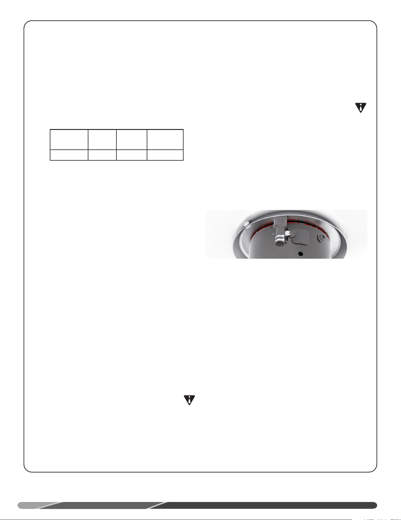
7
INSTALLATION
Emplacement d’installation
Ce chauffe-eau doit être installé en conformité avec les présentes instructions, les codes d’installation locaux, les directives des
fournisseurs de services publics, ou, en l’absence de codes locaux, en conformité avec la plus récente révision du National Fuel
Gas Code aux États-Unis ou du “Code d’installation du gaz naturel et du propane”, CSA-B149.1 au Canada. Une copie peut être
achetée auprès de l’American Gas Association, 400N. Capitol Street NW, Washington, DC 20001: ANSI C223.1 ou National Fire
Protection Association, 1 Batterymarch Park, Quincy, MA 02269 comme livret NFPA 54 pour les États-Unis ou auprès de la Canada
Standards Association, 5060 Spectrum Way, Mississauga (Ontario) L4W5N6 pour le Canada.
Ce chauffe-eau doit être installé dans un endroit où une éventuelle
fuite d’eau du réservoir ou de ses raccords ne résultera pas en
des dommages à l’environnement immédiat du chauffe-eau, ni à
un étage situé plus bas.
Lorsqu’il n’est pas possible de choisir un tel emplacement, il est
recommandé d’installer sous l’appareil un bac d’égouttement
approprié doté d’une capacité de drainage suffisante.
Le bac d’égouttement DOIT être installé conformément aux codes
locaux applicables.
Le chauffe-eau doit être positionné au centre du bac
d’égouttement, comme illustré. Assurez-vous que l’extrémité du
té d’évacuation/collecteur de condensation est orienté vers le bac
d’égouttement.
Le diamètre minimal recommandé du bac d’égouttement est de
710 mm (28 po) pour les modèles de 50 USG et de 810 mm (32
po) pour les modèles de 75 USG.
Il est possible de se procurer un ensemble de bac d’égouttement
chez le fournisseur où le chauffe-eau a été acheté, ou chez tout
autre distributeur de chauffe-eau.
Assurez-vous que la surface de plancher sur laquelle repose le
chauffe-eau possède une capacité portante lui permettant de
soutenir le chauffe-eau rempli d’eau.
Ce chauffe-eau ou tout autre appareil au gaz ne doit jamais être
installé dans un lieu où sont utilisés ou entreposés des liquides
dégageant des vapeurs inflammables, p. ex.: essence, gaz
propane (butane ou propane), peinture, adhésif, diluants, solvants
ou décapants.
AVERTISSEMENT:
De par leur nature volatile, les vapeurs inflammables peuvent
se déplacer, à partir de leur lieu d’entreposage ou d’utilisation,
sur une distance non négligeable. Les flammes nues produites
au brûleur principal du chauffe-eau peuvent provoquer
l’inflammation de ces vapeurs, ce qui peut entraîner la
désactivation du chauffe-eau et donc empêcher son allumage.
Un chauffe-eau au gaz certifié FVIR (résistant à l’allumage
des vapeurs inflammables) peut directement être installé sur
le plancher d’un garage résidentiel (sans plate-forme d’au
moins 18 po (457 mm)), en conformité avec les exigences du
Code d’installation du gaz naturel et du propane, CSA-B149.1
au Canada, ou autrement exigé par les codes provinciaux ou
locaux applicables. Le chauffe-eau doit être installé dans un
endroit où il ne risque pas d’être endommagé par des véhicules
en mouvement ou qui est sujet aux inondations.
IMPORTANT: NE PAS installer ce chauffe-eau dans un lieu où la
température ambiante pourrait dépasser 52°C (125°F).
• L’emplacement d’installation choisi doit permettre de
minimiser la longueur des conduits d’apport d’air et
d’évacuation, ainsi que le nombre de raccords des conduits
d’apport d’air et d’évacuation.
• Lire la section Apport d’air et évacuation, qui présente les
exigences d’installation du système de ventilation.
• Isolez les longues conduites d’eau chaude afin d’économiser
l’eau et l’énergie.
• Le chauffe-eau et ses conduites d’eau doivent être protégés
du gel.
• NE PAS installer ce chauffe-eau à l’extérieur.
• Dégagements minimum aux matières combustibles:
Avant Côtés Arrière Haut
5 po
(127mm)
0 po
(0 cm)
0 po
(0 cm)
15 po
(305 mm)
Le té d’évacuation, situé à l’avant droit de l’appareil, nécessite un dégagement
latéral supplémentaire d’environ 2,75 po.
Le dégagement “Avant” est mesuré entre la chemise du chauffe-
eau et la porte du placard.
*Le dégagement “Haut” est mesuré entre la chemise du chauffe-
eau et le plafond.
AVIS:
Prévoir un dégagement minimal de 38 mm (1-1/2 po) entre
la soupape de sûreté T&P et un mur ou tout obstacle, afin
de permettre son bon fonctionnement et de faciliter son
entretien.
AVERTISSEMENT:
L’expression "structure combustible" se réfère au plafond et
aux murs adjacents et non pas à des produits et matériaux
inflammables se trouvant à proximité. N’entreposez jamais
de produits et matériaux combustibles à proximité de cet
appareil ou de tout autre appareil au gaz.
BAC D’ÉGOUTTEMENT
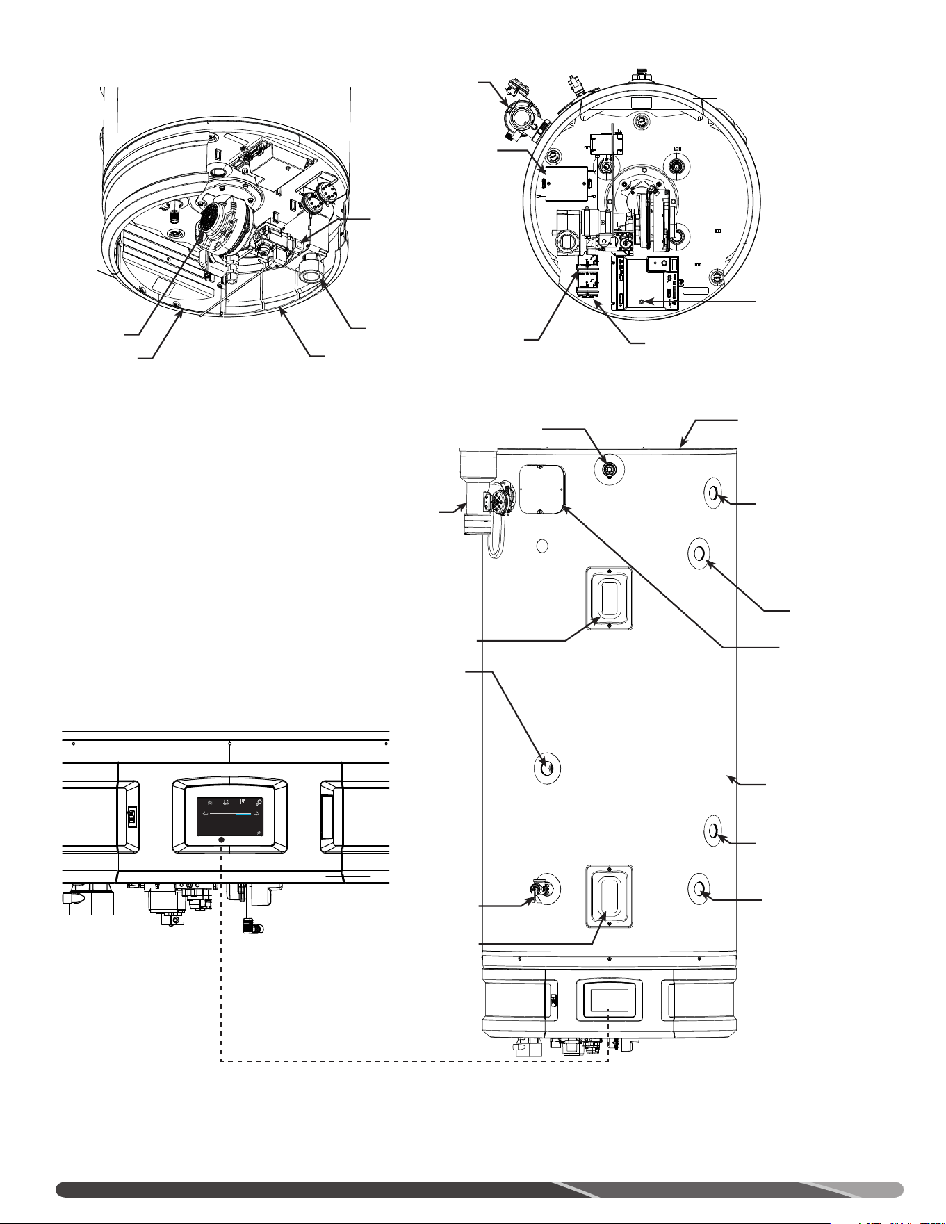
6
DIAGRAMME DES COMPOSANTES
Chemise externe
Détecteur de fuite
Sorties latérales
Entrée latérale
Soupape de
décharge de
température et
de pression
Thermistance
supérieure
Robinet de vidange
Détecteur de fuite
Té d’évacuation
Pressostat
(apport
d’air)
Assemblage
panneau avant
Ventilateur
Panneau latéral
Apport d’air
Pressostat
ventilateur
Commande de l’allumage
Té d’évacuation
Transformateur
Admission gaz
Thermistance
inférieure
Vue avant
Écran tactile
Vue du dessus Vue arrière (isométrique)
Status: Standby
StatusSettings
warm hot very hot
Disable
120°
Service
Anode
Anode
Anode

5
PRÉCAUTIONS GÉNÉRALES DE SÉCURITÉ
!
AVERTISSEMENT:
Une substance odoriférante est ajoutée au gaz naturel et au
propane afin de faciliter la détection d’une éventuelle fuite.
Certaines personnes ne reconnaissent pas cette odeur ou
leur odorat ne fonctionne pas. Si cette odeur typique du gaz
naturel ou du propane ne vous est pas familière, veuillez
consulter votre fournisseur de gaz. En certaines circonstances
cette odeur peut perdre en intensité, ce qui ne lui permet pas
d’indiquer la survenue d’une fuite de gaz.
!
DANGER:
Les chauffe-eau au propane et au gaz propane ne sont pas
construits de la même façon. Ainsi, un chauffe-eau au gaz
naturel alimenté au propane ne peut fonctionner de façon
sécuritaire, et inversement. Ne tentez jamais de convertir un
chauffe-eau au gaz naturel au propane, et inversement. Pour
éviter tout éventuel dommage à l’équipement, toute blessure
ou tout incendie: NE PAS alimenter ce chauffe-eau avec tout
carburant autre que celui indiqué sur sa plaque signalétique.
Alimentez les modèles au propane avec du propane, les
modèles au gaz naturel avec du gaz naturel. Ces appareils ne
sont pas certifiés avec aucun autre carburant.
!
AVERTISSEMENT:
Les appareils au propane ne peuvent être installés sous le
niveau du sol (p. ex.: dans un sous-sol), si une telle installation
est
interdite par les autorités compétentes.
Sécurité relative à l’ali-
mentation électrique
DANGER:
• Risque d’électrocution – Assurez-vous de couper
l’alimentation électrique du chauffe-eau pour éviter une
électrocution, ce qui peut entraîner de graves blessures
ou la mort.
AVERTISSEMENTS:
• Pour votre sécurité, veuillez suivre les directives de
ce manuel pour minimiser les risques d’incendie,
d’explosion, d’électrocution, de dommages matériels, de
blessures ou de décès.
• Les raccordements électriques et les mises à la masse
doivent être conformes aux codes électriques locaux ou,
en l’absence de codes locaux, en conformité avec, aux
États-Unis, le National Electrical Code (ANSI/NFPA 70) ou
au Canada, le Code canadien de l’électricité (CAN/CSA
C22.1, première partie).
ATTENTION:
• Étiquetez tous les fils avant de les déconnecter lors de
travaux d’entretien. Des erreurs de reconnexion peuvent
causer un fonctionnement dangereux ou erratique.
Assurez-vous du bon fonctionnement du chauffe-eau à
la suite de tout entretien.
• Pour votre sécurité, l’inspection et le nettoyage du
brûleur devraient être uniquement effectués par un
technicien qualifié.
• Assurez-vous de couper l’alimentation électrique du
chauffe-eau avant de retirer son couvercle. Tout contact
avec une pièce en mouvement ou sous tension peut
entraîner de graves blessures.
• NE PAS tenter de corriger l’alimentation électrique ou
en gaz, de réparer la commande du gaz, les brûleurs,
les conduits de ventilation ou tout dispositif de sécurité.
Faites plutôt appel à un technicien d’entretien qualifié.
INSTALLATION DANS L’ÉTAT DE
LA CALIFORNIE
La loi californienne requiert que les tous les chauffe-eau
commerciaux, neufs et de remplacement, soient contreventés,
ancrés ou attachés de façon à éviter toute chute ou à
empêcher tout déplacement horizontal lors d’un séisme. Au
minimum, tout chauffe-eau doit être fixé conformément au
California Plumbing Code ou aux modifications apportées à
celui-ci par une ville ou un comté conformément à l’article
17958.5. Les instructions génériques pour la Californie
intitulées «Guidelines for Earthquake Bracing Commercial
Water Heaters» peuvent être obtenues en:
• Écrivant au California Department of General Services,
Division of State Architect, 1102 Q Street, Suite 5100,
Sacramento, CA 95814
• Appelant au 916-445-8100
• Adresse Web suivante:
https://www�dgs�ca�gov/-/media/Divisions/DSA/Publications/
gas_shutoff/waterheaterbracing
Inspectez le chauffe-
eau à la réception
Inspectez attentivement le chauffe-eau avant d’entreprendre
l’installation, afin de détecter un éventuel dommage. Portez
une attention particulière au conduit d’apport d’air comburant,
au té d’évacuation et à la soupape de sécurité. Si vous
détectez des dommages, NE PAS installer ou tenter de réparer
le chauffe-eau. Contactez le fabricant comme indiqué sous
«OBTENIR DU SOUTIEN TECHNIQUE».
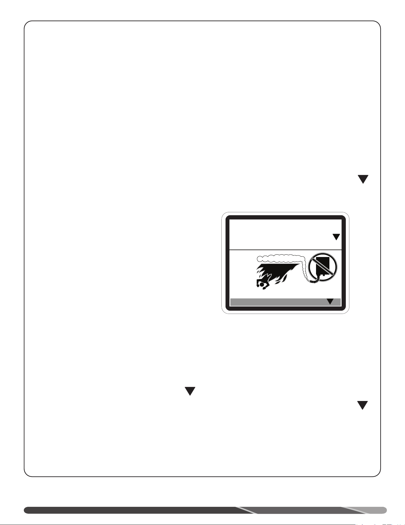
4
PRÉCAUTIONS GÉNÉRALES DE SÉCURITÉ
Assurez-vous de lire et de comprendre toutes les instructions du Manuel d’utilisation et d’entretien avant d’entreprendre
l’installation ou d’utiliser ce chauffe-eau. Cela vous permettra d’économiser temps et argent. Portez une attention particulière aux
Instructions de sécurité. Le non-respect de ces avertissements peut entraîner de graves blessures ou la mort. Si vous avez de la
difficulté à comprendre les instructions de ce manuel ou si vous avez des questions, ARRÊTEZ et obtenez l’aide d’un technicien
d’entretien qualifié ou du distributeur de gaz local.
Ventilation:
!
DANGER:
Le défaut de ventiler le chauffe-eau à l’extérieur du bâtiment
comme indiqué dans la section "Apport d’air et évacuation"
du présent manuel peut entraîner son fonctionnement non
sécuritaire. Afin d’éviter les risques d’incendie, d’explosion ou
d’asphyxie des occupants au monoxyde de carbone, ne faites
jamais fonctionner le chauffe-eau s’il n’est pas correctement
ventilé et s’il ne dispose pas d’un apport d’air adéquat assurant
son bon fonctionnement. Inspectez les conduits d’apport d’air
et d’évacuation afin de vérifier leur bonne installation, lors de la
mise en service et périodiquement par la suite. Reportez-vous à
la section “Entretien” du présent manuel pour plus d’information
relative à l’inspection du système de ventilation.
Matières inflammables:
!
AVERTISSEMENT:
La manutention d’essence ou de tout autre produit ou liquide
inflammable (adhésifs, solvants, diluant, etc.), ou leurs
dégagements de vapeurs inflammables sont extrêmement
dangereux. NE PAS utiliser ou entreposer d’essence ni aucune
autre matière inflammable ou combustible à proximité d’un
chauffe-eau ou de tout autre appareil. Veuillez lire et respecter
les messages d’avertissement contenus ci-dessous dans
le présent manuel et ceux des étiquettes apposées sur le
chauffe-eau. Le non-respect de cette directive peut entraîner
des dommages matériels, de graves blessures ou la mort.
Sécurité relative au gaz
naturel et au propane
!
DANGER:
MODÈLES AU PROPANE — Le gaz propane doit être utilisé
avec une grande prudence.
• Comme ce gaz est plus lourd que l’air, il s’accumule
dans les dépressions du sol et n’atteint pas rapidement
les narines.
• Avant toute tentative d’allumage du chauffe-eau,
inspectez-le et sentez aux alentours afin de détecter une
éventuelle fuite de gaz. Effectuez un essai d’étanchéité
de tous les raccords avec une solution savonneuse. La
présence de bulles indique la présence d’une fuite; elle
doit être colmatée.
• Lorsque vous humez pour détecter une fuite, assurez de
vérifier au niveau du sol.
• Il est recommandé d’installer un détecteur de
propane; veuillez l’installer en conformité avec les
recommandations de son fabricant et la réglementation
locale.
• Il est recommandé d’utiliser plus qu’une seule méthode
pour détecter une éventuelle fuite de propane.
SI VOUS DÉTECTEZ OU SUSPECTEZ UNE FUITE DE GAZ
PROPANE:
• NE PAS tenter d’en déterminer la cause vous-même;
• NE PAS mettre aucun appareil en marche dans le
bâtiment;
• NE PAS actionner aucun interrupteur électrique;
• NE PAS utiliser aucun téléphone dans votre bâtiment.
• Quittez immédiatement le bâtiment, évacuez votre
famille et vos animaux.
• Laissez les portes ouvertes pour ventiler les lieux et
joignez le fournisseur de gaz, un centre de service agréé
ou le service des incendies.
• Ne retournez pas à l’intérieur du bâtiment avant que la
réparation ait été effectuée, la fuite colmatée et qu’une
personne compétente ait établi que les lieux sont
sécuritaires.
!
!
INFLAMMABLE
Vapeurs inflammables
RISQUE D’INCENDIE ET D’EXPLOSION
Peut causer de graves blessures ou la mort.
Ne pas ranger ni utiliser de l’essence ou d’autres liquides ou vapeurs
inflammables à proximité de cet appareil ou de tout autre appareil. L’entreposage
ou l’utilisation d’essence ou d’autres liquides ou vapeurs inflammables à proximité
de ce chauffe-eau peut causer de graves blessures ou la mort.
A V E R T ISSE M E N T
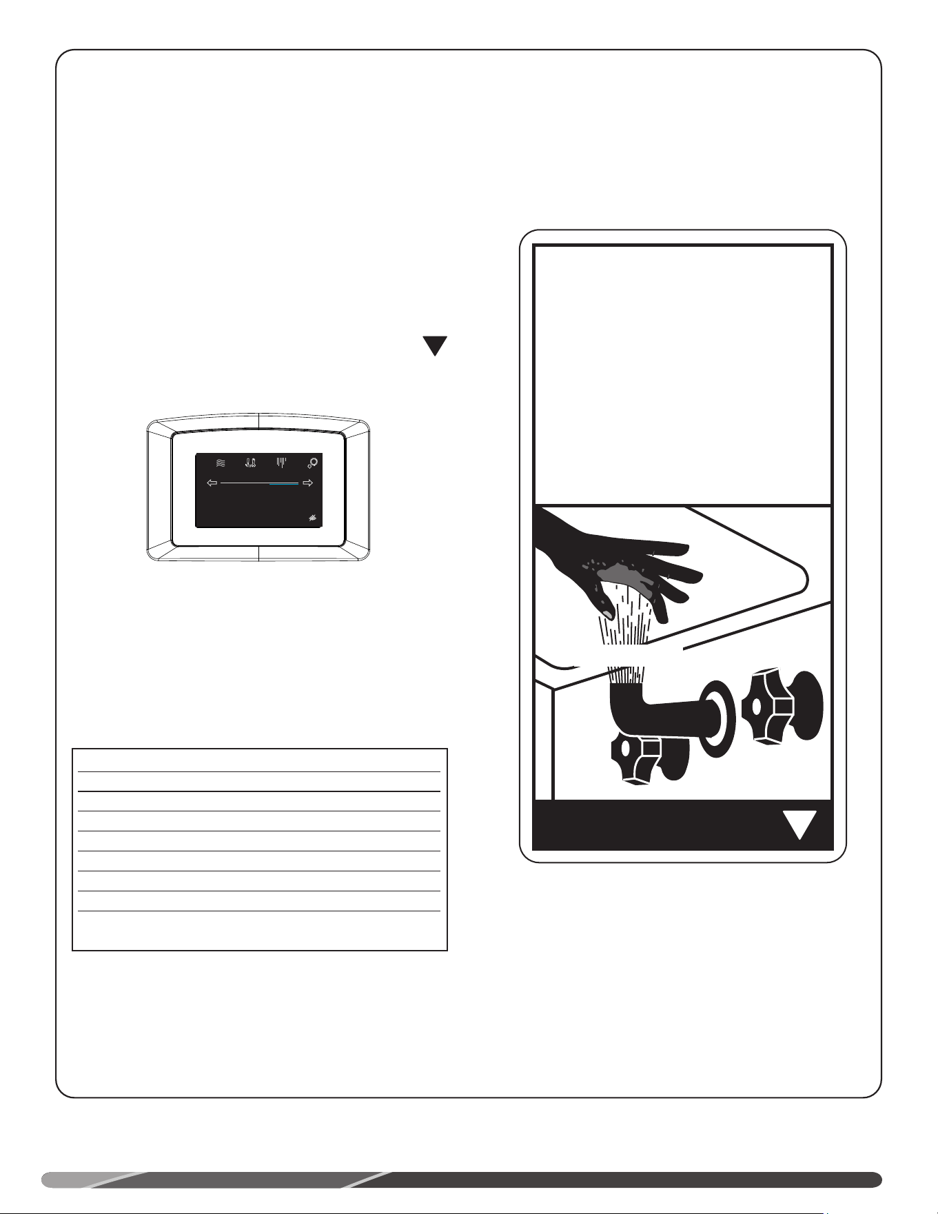
3
PRÉCAUTIONS GÉNÉRALES DE SÉCURITÉ
Afin de satisfaire aux applications commerciales, la
température de consigne de ce chauffe-eau est réglable
jusqu’à 85°C (185°F). Toutefois, de l’eau chauffée à plus
de 52°C (125°F) peut instantanément causer de graves
brûlures ou la mort par ébouillantage. Il est suggéré de
régler l’appareil à cette température dans les applications
générales de chauffage de l’eau.
La sécurité des utilisateurs et l’économie d’énergie sont les
deux principaux facteurs à considérer lors de la sélection
de la température de consigne. Le réglage de température le
plus économique est le plus bas permettant de répondre aux
besoins de l’application.
La température la plus élevée dans le réservoir est
atteinte au moment de l’arrêt du brûleur. Pour découvrir la
température de l’eau chaude générée, ouvrez un robinet
d’eau chaude et immergez un thermostat dans le jet d’eau
chaude.
Le tableau qui suit présente la relation entre la
température de l’eau chaude et la durée d’exposition pour
produire un ébouillantage; veuillez vous y référer pour
sélectionner la température de consigne sécuritaire de
votre application.
La température de consigne de l’eau dans le réservoir du
chauffe-eau peut être changée par la modification du réglage
affiché à l’écran (voir section «Interface-utilisateur»). Afin
de respecter la réglementation de sécurité en vigueur, la
température de consigne du chauffe-eau est réglée à sa
plus basse valeur en usine. Les illustrations de la section
«Interface-utilisateur» présentent l’afficheur et les
instructions de modification de la température de consigne.
DANGER:
La sélection d’une température plus élevée augmente les
risques D’ÉBOUILLANTAGE.
AVIS:
Il est recommandé d’installer une vanne thermostatique
qui réduit la température de l’eau dans le système de
distribution d’eau en entier, par l’ajout d’eau froide à la
canalisation principale d’eau chaude. Il est recommandé
d’installer une vanne thermostatique conforme à la
norme “Standard for Temperature Actuated Mixing Valves
for Hot Water Distribution Systems, ASSE 1017”. Voir
Raccords d’eau pour plus de détails. Communiquez avec
un plombier licencié ou l’autorité compétente locale en
matière de plomberie pour obtenir plus de détails.
Température de l’eau Durée produisant une brûlure
grave
49°C (120°F) Plus de 5 minutes
52°C (125°F) 1,5 à 2 minutes
54°C (130°F) Environ 30 secondes
57°C (135°F) Environ 10 secondes
60°C (140°F) Moins de 5 secondes
63°C (145°F) Moins de 3 secondes
66°C (150°F) Environ 1,5 seconde
68°C (155°F) Environ 1 seconde
Tableau avec l’aimable autorisation du Shriners Burn Institute
ÉBOUILLANTAGE EN FONCTION DE LA DURÉE
D’EXPOSITION ET DE LA TEMPÉRATURE
Voir section «Interface-utilisateur» pour les instructions de réglage
de la température�
!
Status: Standby
StatusSettings
warm hot very hot
Disable
120°
Service
DANGER
!
CHAUDE
De l’eau chauffée à plus de 125°F (52°C)
peut instantanément causer de graves
brûlures ou la mort par ébouillantage.
Les enfants, les personnes âgées et
les personnes handicapées présentent
un risque plus élevé d’ébouillantage.
Veuillez consulter le manuel d’instructions
avant de régler la température du
chauffe-eau.
Vérifiez la température de l’eau avant de
prendre un bain ou une douche.
Il existe des robinets qui permettent de
limiter la température de l’eau chaude.
Consultez le manuel
BRÛLURE
Importante information de sécurité
Précautions générales de sécurité ��������������������������������������� 2−5
Information produit
Diagramme des composantes ���������������������������������������������������� 6
Installation
Emplacement d’installation ��������������������������������������������������������7
Expansion thermique ������������������������������������������������������������������ 8
Raccords d’eau ��������������������������������������������������������������������������� 8
Remplissage du chauffe-eau �����������������������������������������������������9
Alimentation en gaz �������������������������������������������������������������������� 9
Essai d’étanchéité ����������������������������������������������������������������������9
Condensation ������������������������������������������������������������������������������ 9
Haute altitude ���������������������������������������������������������������������������10
Alimentation électrique ������������������������������������������������������������10
Installation-type ������������������������������������������������������������������������11
Schéma de plomberie, chauffage des locaux 12
Apport d’air et évacuation ������������������������������������������������ 13 - 32
Liste de vérification ������������������������������������������������������������������33
Utilisation
Instructions d’allumage ������������������������������������������������������������34
Précautions de sécurité ������������������������������������������������������������ 35
Interface-utilisateur
Mise en service ����������������������������������������������������������������������� 36
Réglage de la température ������������������������������������������������������� 36
Programmation de l’horaire������������������������������������������������������37
Réglages heure/date ����������������������������������������������������������������37
Statut Wi-Fi ������������������������������������������������������������������������������� 38
Alarmes et alertes d’entretien �������������������������������������������������� 39
Entretien
Entretien périodique préventif ������������������������������������������������� 40
Utilisation saisonnière ��������������������������������������������������������������40
Système de ventilation �������������������������������������������������������������40
Avant d’appeler un réparateur
Guide de dépannage ���������������������������������������������������������� 41-42
Codes d’erreur �������������������������������������������������������������������� 43-48
Pièces de rechange
Instructions pour la commande de pièces de rechange 49
Schémas électriques ........................................................50
Obtenir du soutien technique ...........................................52
2
TABLE DES MATIÈRES
Votre sécurité et celle de votre entourage sont très importantes.
Le présent manuel et des autocollants apposés sur votre appareil
fournissent plusieurs importants messages de sécurité. Lisez et
suivez toujours tous les messages de sécurité.
Ceci est le symbole d’avertissement du danger.
Portez attention
à ce symbole, il précède d’importantes
informations
de sécurité! Ce symbole vous alerte à propos de
dangers pouvant entraîner des blessures ou
ou la mort.
Tous les messages de sécurité sont précédés du symbole
d’avertissement du danger ou des mots « DANGER », «
AVERTISSEMENT », « ATTENTION » ou « AVIS ».
Ces mots ont la signification suivante:
LISEZ LES DIRECTIVES DE SÉCURITÉ
POUR VOS DOSSIERS:
Veuillez inscrire les n° de modèle et de série ci-dessous:
Ces numéros sont sur une étiquette apposée sur l’appareil.
Brochez la facture ou le reçu d’achat ici.
Il est obligatoire de présenter l’original de la preuve d’achat pour
obtenir du service au titre de la garantie.
DANGER:
AVIS:
!
ATTENTION:
!
AVERTISSEMENT:
Signale un danger imminent pouvant entraîner de graves blessures ou la mort.
Signale une situation potentiellement dangereuse pouvant entraîner des
dommages matériels, de graves blessures ou la mort.
Signale une situation potentiellement dangereuse pouvant entraîner des
blessures mineures ou modérées.
Attire votre attention sur l’importance de suivre la procédure présentée ou de
s’assurer du maintien d’une condition précise.
!
CHAUFFE-EAU COMMERCIAUXCHAUFFE-EAU COMMERCIAUX
À HAUTE EFFICACITÉÀ HAUTE EFFICACITÉ
MANUEL D’UTILISATION ET MANUEL D’UTILISATION ET
D’ENTRETIEND’ENTRETIEN
AP23779
NE PAS jeter ce manuel.
Veuillez le lire attentivement
et le conserver pour référence
ultérieure.
AVERTISSEMENT
Tout manquement aux présentes
instructions peut causer un incendie
ou une explosion entraînant des
dommages matériels, des blessures
ou la mort.
POUR VOTRE
SÉCURITÉ!
• NE PAS entreposer ou utiliser
de l’essence ni d’autres liquides
inflammables ou dégageant des
vapeurs inflammables à proximité
de cet appareil ni de tout autre
appareil. Le non-respect de cette
directive peut causer un incendie
ou une explosion.
- SI VOUS DÉTECTEZ UNE ODEUR
DE GAZ
• NE METTEZ AUCUN appareil en
marche.
• N’ACTIONNEZ AUCUN interrupteur
électrique.
• N’UTILISEZ PAS de téléphone dans
votre maison.
• Appelez immédiatement votre
fournisseur de gaz de chez un
voisin et suivez les directives du
fournisseur de gaz.
• Si vous ne pouvez communiquer
avec votre fournisseur de gaz,
appelez le Service des incendies.
• NE RETOURNEZ PAS dans votre
logement sans l’autorisation du
distributeur de gaz ou du service
des incendies.
- REPORTEZ-VOUS TOUJOURS AU
PRÉSENT MANUEL
• L’installation et la réparation
de cet appareil doivent être
effectuées par un installateur
qualifié, un centre de service
licencié ou le fournisseur de
service du gaz.
D
E
S
I
G
N
C
E
R
T
I
F
I
E
D
®