Models
Refrigerated Prep Table with Raised Rail
Refrigerated Kitchen Equipment
Steelheart B Series
Instruction Manual
Issued: 1-5-2022
Revised: 3-11-2025
hoshizakiamerica.com
2
WARNING
Only qualied service technicians should install and service the appliance. To
obtain the name and phone number of your local Hoshizaki Certied Service
Representative, visit www.hoshizakiamerica.com. No installation or service should
be undertaken until the technician has thoroughly read this Instruction Manual.
Likewise, the owner/manager should not proceed to operate the appliance until the
installer has instructed them on its proper operation. Failure to install, operate, and
maintain the appliance in accordance with this manual may adversely affect safety,
performance, component life, and warranty coverage. Proper installation is the
responsibility of the installer. Product failure or property damage due to improper
installation is not covered under warranty.
Hoshizaki provides this manual primarily to assist qualied service technicians in the
installation, maintenance, and service of the appliance.
Should the reader have any questions or concerns which have not been satisfactorily
addressed, please call, send an e-mail message, or write to the Hoshizaki Technical
Support Department for assistance.
Phone: 1-800-233-1940; (770) 487-2331
E-mail: techsuppor[email protected]
618 Highway 74 South
Peachtree City, GA 30269
Attn: Hoshizaki Technical Support Department
NOTE: To expedite assistance, all correspondence/communication MUST include the
following information:
• Model Number
• Serial Number
• Complete and detailed explanation of the problem.

3
CONTENTS
Important Safety Information ................................................................................................. 5
I. Installation Instructions ....................................................................................................... 9
A. Location ........................................................................................................................ 9
B. Checks Before Installation ........................................................................................... 10
C. Setup ........................................................................................................................... 10
1. Remove the Appliance from the Pallet ................................................................... 10
2. Check the Refrigeration Circuit .............................................................................. 12
3. Position the Appliance and Lock the Front Casters .............................................. 12
4. Install the Shelves .................................................................................................. 12
5. Conrm Rail Cover Operation ................................................................................ 12
6. Properly Align Pans and Rail Dividers.................................................................... 13
7. Attach the Cutting Board ......................................................................................... 15
D. Door Reversal.............................................................................................................. 16
E. Door/Drawer Reversal ................................................................................................. 20
F. Electrical Connection ................................................................................................... 27
G. Final Checklist ............................................................................................................ 28
II. Operating Instructions ...................................................................................................... 29
A. Important Notes About Usage ..................................................................................... 29
B. Pre-Startup and Startup .............................................................................................. 32
C. Controls and Adjustments ........................................................................................... 34
1. Rail Area Day Mode and Night Mode Temperature Control .................................... 35
2. Cabinet Temperature Control and Display ............................................................. 36
D. Cabinet Control Display Icons ..................................................................................... 37
E. Defrost ......................................................................................................................... 38
F. Cabinet Control Alarm Safeties .................................................................................... 40
G. Food Storage .............................................................................................................. 41
H. Safety Devices ............................................................................................................ 41
I. Cooling Performance .................................................................................................... 42
J. Cabinet Condensation ................................................................................................. 42
III. Cleaning and Maintenance Instructions .......................................................................... 43
A. Cleaning ...................................................................................................................... 43
1. Exterior ................................................................................................................... 43
2. Cabinet Interior ...................................................................................................... 43
3. Door/Drawer Gaskets ............................................................................................ 43
4. Shelves .................................................................................................................. 43
5. Rail Light Sensor ................................................................................................... 43
6. Drawers ................................................................................................................. 44
7. Cutting Board ......................................................................................................... 44
8. Pans....................................................................................................................... 44
9. Rail, Rail Dividers, and Rail Cover ......................................................................... 44
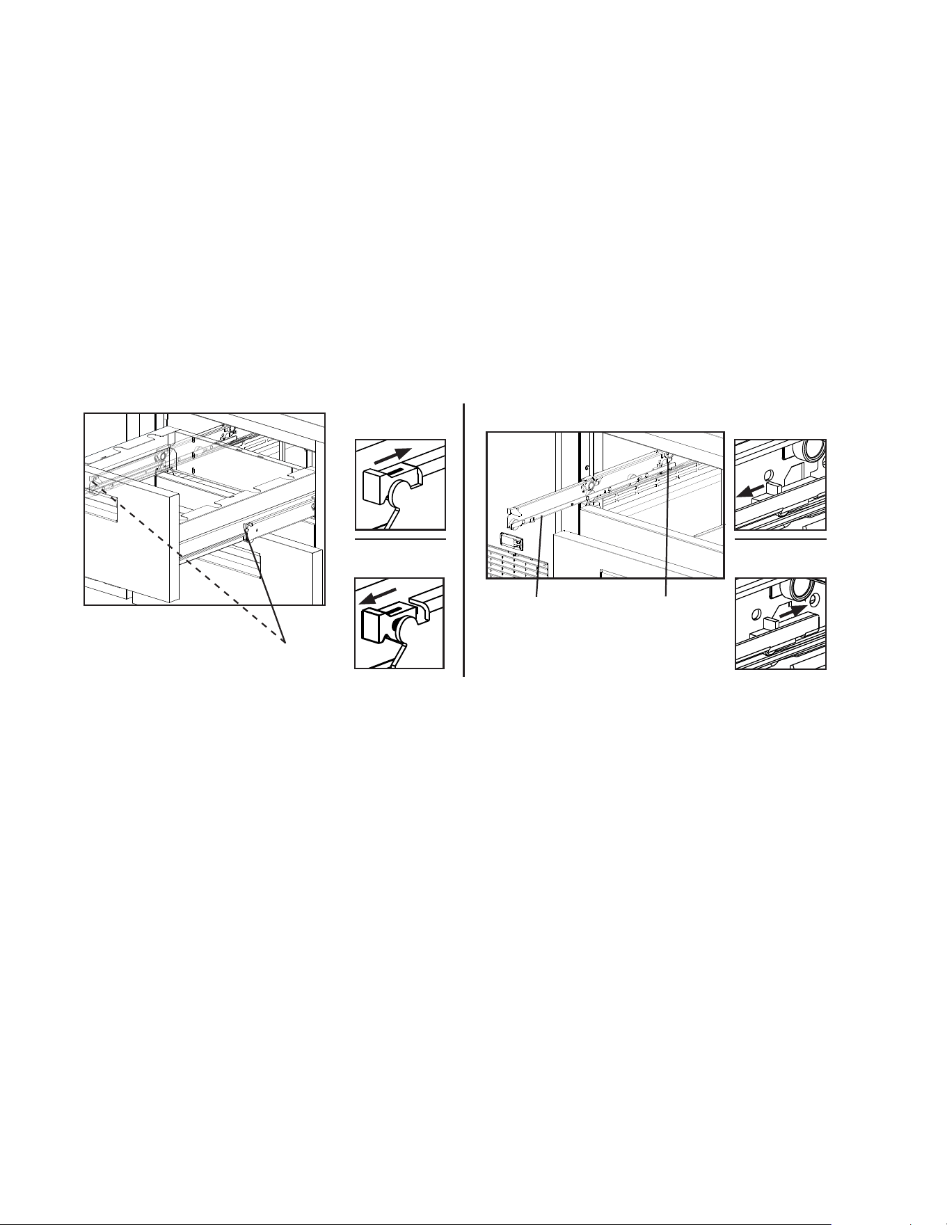
10. Rail Air Duct ......................................................................................................... 45
IMPORTANT
This manual should be read carefully before the appliance is installed and operated.
Read the warnings and guidelines contained in this booklet carefully as they
provide essential information for the continued safe use and maintenance of the
appliance. Retain this booklet for any further reference that may be necessary.

4
B. Maintenance ................................................................................................................ 46
1. Air Filter .................................................................................................................. 46
2. Condenser ............................................................................................................. 46
3. Condensate Drain Hose ........................................................................................ 46
4. Power Supply Connection ...................................................................................... 46
IV. Preparing the Appliance for Periods of Non-Use ............................................................ 47
V. Disposal ........................................................................................................................... 48
5
Important Safety Information
Throughout this manual, notices appear to bring your attention to situations which could
result in death, serious injury, damage to the appliance, or damage to property.
DANGER
Indicates a hazardous situation that, if not avoided, will result in
death or serious injury.
WARNING
Indicates a hazardous situation that, if not avoided, could result
in death or serious injury.
NOTICE
Indicates a situation that, if not avoided, could result in damage
to the appliance or property.
IMPORTANT
Indicates important information about the use and care of the
appliance.
DANGER
Risk of Fire or Explosion
Flammable Refrigerant Used
• Follow handling instructions carefully
in compliance with U.S. government
regulations.
• Do not use mechanical devices to defrost.
• Do not puncture refrigerant tubing. Risk
of re or explosion due to puncture
of refrigerant tubing; follow handling
instructions carefully.
• Component parts shall be replaced with
like components.
• Servicing shall be done by factory
authorized service personnel to minimize
the risk of possible ignition due to
incorrect parts or improper service.
• Consult instruction manual/service manual
before attempting to install or service this
product. All safety precautions must be
followed.
• Dispose of properly in accordance with
federal or local regulations.
• Do not place any potential ignition sources
in or near the appliance.
Risque De Feu Ou D'Explosion
Le Frigorigène Est Inammable
• Suivre attentivement les instructions
de manipulation conformément à la
réglementation gouvernementale.
• Ne pas utiliser d'appareils mécaniques
pour dégivrer le réfrigérateur.
• Ne pas perforer la tubulure contenant le
frigorigène. Risque de feu ou d'explosion
si la tubulure contenant le frigorigène
est perforée; suivre les instructions de
manutention avec soin.
• Les pièces des composants doivent être
remplacées par des pièces et accessoires
équivalents.
• L’entretien doit être effectué par le
personnel de service autorisé par le
fabricant an de minimiser les risques
d’inammation attribuables à l’installation
d’une pièce inadéquate ou à la mauvaise
exécution du service.
• Consulter le manuel du propriétaire/
guide de réparation avant de tenter une
réparation. Toutes les mesures de sécurité
doivent être respectées.
• Éliminer conformément aux règlements
fédéraux ou locaux.
• Ne placez aucune source d’inammation
potentielle dans ou près de l’appareil.
6
WARNING
The appliance should be destined only to
the use for which it has been expressly
conceived. Any other use should be
considered improper and therefore
dangerous. The manufacturer cannot be
held responsible for injury or damage
resulting from improper, incorrect, and
unreasonable use. Failure to install,
operate, and maintain the appliance
in accordance with this manual will
adversely affect safety, performance,
component life, and warranty coverage.
To reduce the risk of death, electric
shock, serious injury, or re, follow
basic precautions including the
following:
• Only qualied service technicians should
install and service the appliance.
• Wear appropriate personal protective
equipment (PPE) when servicing the
appliance.
• The appliance must be installed in
accordance with applicable national, state,
and local codes and regulations.
• Appliance is heavy. Use care when lifting
or positioning. Work in pairs when needed
to prevent injury or damage.
Do not lift using the top section or the
doors/drawers.
• To reduce the risk of electric shock, do not
touch the plug with damp hands.
• Unplug the appliance before servicing.
• The appliance requires an independent
power supply of proper capacity. See the
nameplate for electrical specications.
Failure to use an independent power
supply of proper capacity can result in a
tripped breaker, blown fuse, damage to
existing wiring, or component failure.
This could lead to heat generation or re.
• THE APPLIANCE MUST BE
GROUNDED. The appliance is equipped
with a NEMA5-15 three-prong grounding
plug to reduce the risk of potential
shock hazards. It must be plugged into a
properly grounded, independent 3-prong
wall outlet. If the outlet is a 2-prong outlet,
it is your personal responsibility to have
a qualied electrician replace it with a
properly grounded, independent 3-prong
wall outlet. Do not remove the ground
prong from the power cord and do not use
an adapter plug. Failure to follow these
instructions may result in death, electric
shock, or re.
• Do not use an extension cord.
• Do not use an appliance with a damaged
power cord. The power cord should not be
altered, jerked, bundled, weighed down,
pinched, or tangled. Such actions could
result in electric shock or re. To unplug
the appliance, be sure to pull the plug, not
the cord, and do not jerk the cord.
• The GREEN ground wire in the
factory-installed power cord is connected
to the appliance. If it becomes necessary
to remove or replace the power cord, be
sure to connect the power cord's ground
wire.
• Do not splash, pour, or spray water directly
onto or into the appliance.
This might cause short circuit, electric
shock, corrosion, or failure.
• Do not make any alterations to the
appliance. Alterations could result in
electric shock, injury, re, or damage to
the appliance.
• The appliance is not intended for use by
persons (including children) with reduced
physical, sensory, or mental capabilities,
or lack of experience and knowledge,
unless they have been given supervision
or instruction concerning use of the
appliance by a person responsible for their
safety.
7
• Do not block air inlets or outlets, otherwise
cooling performance may be reduced.
• Do not tightly pack the cabinet. Allow some
space between items to ensure good air
ow. Also allow space between items and
interior surfaces.
• Do not put warm or hot foods in the cabinet.
Let them cool rst, or they will raise the
cabinet temperature and could deteriorate
other foods in the cabinet or overload the
appliance.
• Food storage and handling must comply
with applicable codes and regulations.
• All foods should be wrapped in plastic lm
or stored in sealed containers. Otherwise
foods may dry up, pass their smells onto
other foods, cause frost to develop, result
in poor appliance performance, or increase
the likelihood of cross-contamination.
Certain dressings and food ingredients,
if not stored in sealed containers, may
accelerate corrosion of the evaporator,
resulting in failure.
• Do not store items near air outlets.
Otherwise, items may freeze up and
crack or break causing a risk of injury or
contamination of other food.
• The entire rail must always be covered
by rail dividers and pans. Otherwise, the
appliance will not cool properly. Use only
pans up to 6"(15cm) deep. Do not use
damaged rail dividers or pans. For rail
divider and pan combinations, see "I.C.6.
Properly Align Pans and Rail Dividers."
• Ingredients must be pre-chilled to 37°F
(3°C) or less before placing in rail.
• Keep the rail cover closed when not actively
preparing food.
• The rail is for keeping ingredients cool while
preparing food. If not actively preparing
food for a long period such as overnight,
seal pans with plastic wrap in addition to
closing the rail cover.
• For PR46B(-D2), all 6 casters must be
installed. Otherwise, the appliance may tip,
resulting in injury or damage.
WARNING, continued
• Children should be properly supervised
around the appliance.
• Do not climb, stand, or hang on the
appliance or doors/drawers or allow
children or animals to do so. Do not climb
into the appliance or allow children or
animals to do so. Death or serious injury
could occur or the appliance could be
damaged.
• Be careful not to pinch ngers when
opening and closing the doors/drawers
or rail cover or when handling food pans.
Be careful when opening and closing the
doors/drawers or rail cover when children
are in the area.
• Open and close the doors/drawers and
rail cover with care. Opening the doors/
drawers or rail cover too quickly or
forcefully may cause injury or damage to
the appliance or surrounding equipment.
• Do not use combustible spray or place
volatile or ammable substances in or near
the appliance. They might catch re.
• Keep the area around the appliance clean.
Dirt, dust, or insects in the appliance could
cause harm to individuals or damage to
the equipment.
• Do not throw anything onto the shelves or
load any single shelf with more than 120lb.
(54.5 kg) of product. They might fall off and
cause injury.
• Do not load any single drawer with more
than 75 lb. (34 kg) of product. Depending
on the weight of product in the drawers,
secure the appliance as necessary to
prevent it from overturning. Do not open
more than one drawer at a time.
• The appliance is designed only for
temporary storage of food. Employ sanitary
methods. Use for any other purposes (for
example, storage of chemicals or medical
supplies such as vaccine and serum)
could cause deterioration of stored items.

8
NOTICE
• Protect the oor when moving the
appliance to prevent damage to the oor.
• Keep ventilation openings clear of
obstruction.
• The factory-installed rear bumpers
must be in place to ensure proper rear
clearance. Blockage of airow could
negatively affect performance and
damage the appliance.
• Do not allow the appliance to bear any
outside weight.
• To prevent deformation or cracks, do not
spray insecticide onto the plastic parts or
let them come into contact with oil.
• To avoid damage to the gasket, use only
the door/drawer handle when opening
and closing.
• Do not leave the doors/drawers open.
• To avoid damage to the top seal, do not
lift the appliance by the top section or
remove the top section.
• Do not place anything on top of the rail
cover. The rail cover is not designed to
bear any outside weight.
• Do not place anything on the air duct
panels beneath the pans in the rail.
The air duct panels are not load-bearing.
• A minimum of 10"(25cm) clearance above
the rail should be provided to allow the rail
cover to open.
9
I. Installation Instructions
WARNING
• The appliance must be installed in accordance with all applicable national, state,
and local regulations.
• Appliance is heavy. Use care when lifting or positioning. Work in pairs when
needed to prevent injury or damage. Do not lift using the refrigeration area, the
top section, or the doors/drawers.
• Do not tilt the appliance more than 45°.
A. Location
WARNING
• The appliance is not intended for outdoor use.
• Certied to maintain NSF temperatures between 45°F to 86°F (7°C to 30°C).
Engineered to maintain NSF temperatures up to 100°F (38°C).
• Operation of the appliance, for extended periods, outside of these temperature
ranges may affect appliance performance.
For best operating results:
• The appliance should not be located next to ovens, grills, or other high heat producing
equipment.
• The location should provide a rm and level foundation for the appliance.
• The appliance should not be located in a corrosive environment.
• Allow 1" (3 cm) clearance at sides for proper air circulation. The factory-installed rear
bumpers must be in place to ensure proper rear clearance. A minimum of 10"(25cm)
clearance above the rail should be provided to allow the rail cover to open.
10
B. Checks Before Installation
WARNING
Refer to the nameplate for electrical specications. The nameplate is located on
the right side wall of the cabinet interior. For more electrical connection details, see
"I.F. Electrical Connection." We reserve the right to make specication and design
changes without prior notice.
• Visually inspect the exterior of the shipping package and immediately report any damage
to the carrier. Upon opening the package, any concealed damage should also be
immediately reported to the carrier.
• Remove the shipping carton, tape, and packing material. Also remove the protective plastic
lm from both the exterior panels and the interior door/drawer panel. If the appliance is
exposed to the sun or to heat, remove the lm after the appliance cools.
• Remove all accessory containers before discarding the packing materials. Dispose of all
packing materials in a proper and environmentally responsible manner.
• Check for missing or damaged accessories.
C. Setup
1. Remove the Appliance from the Pallet
1) Move as close to the nal location as possible.
2) Remove the 2 bolts securing the appliance to the pallet, then remove the appliance
from the pallet. Block the appliance securely at a height of 8" (20 cm) off the oor.
NOTICE! Do not place blocks under the refrigeration area or doors/drawers of the
appliance. Do not lay the appliance down.
Nameplate
11
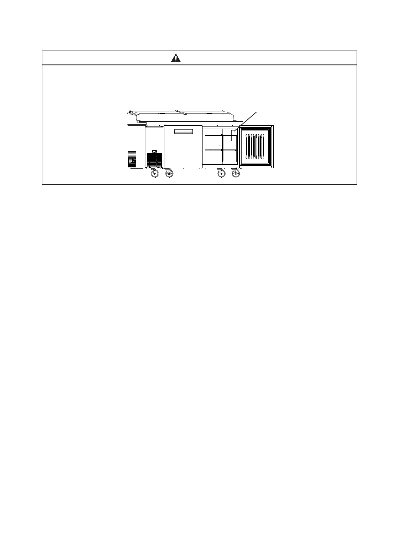
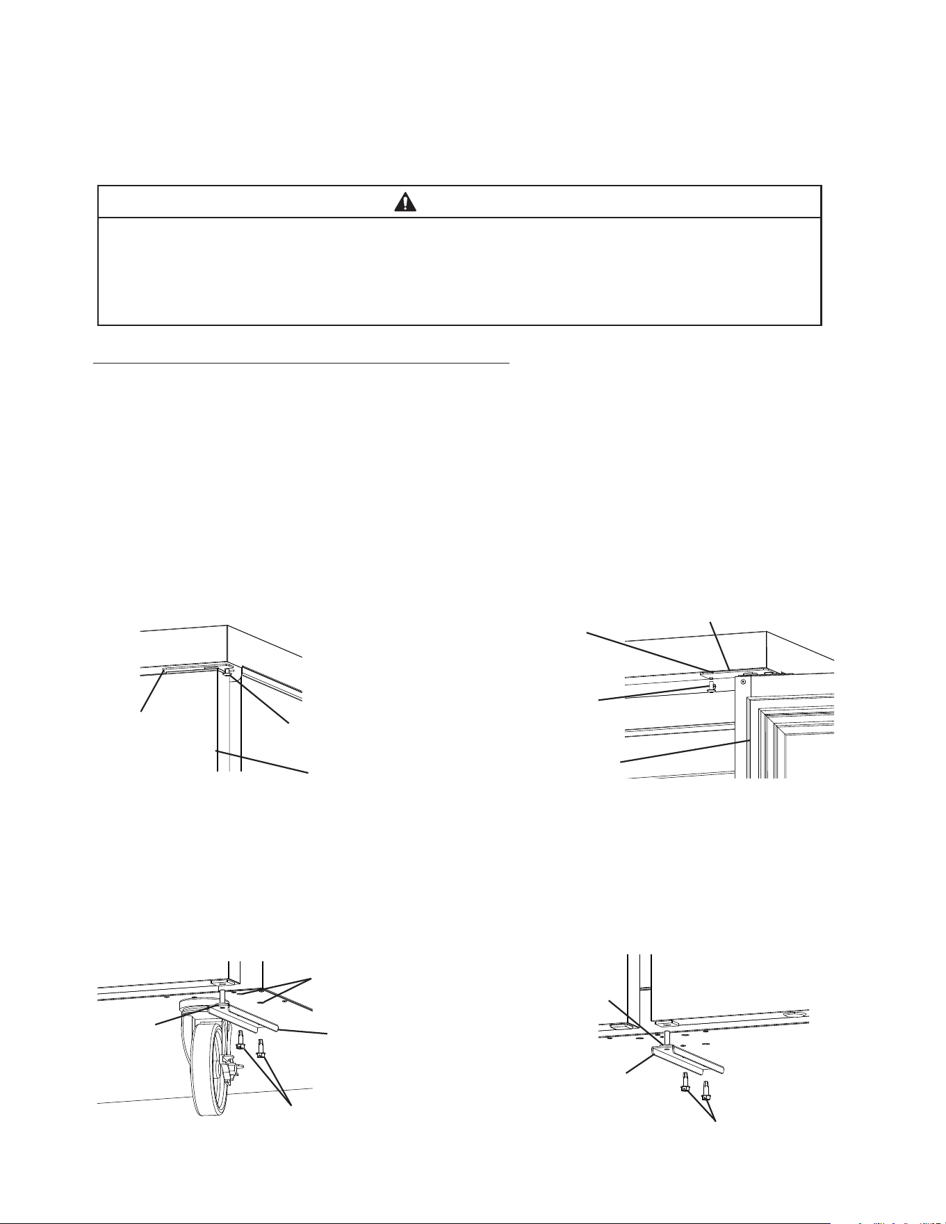
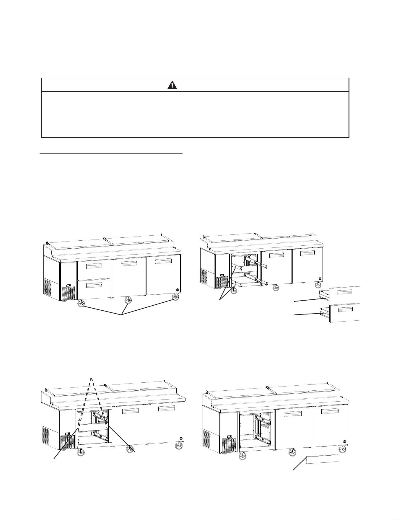
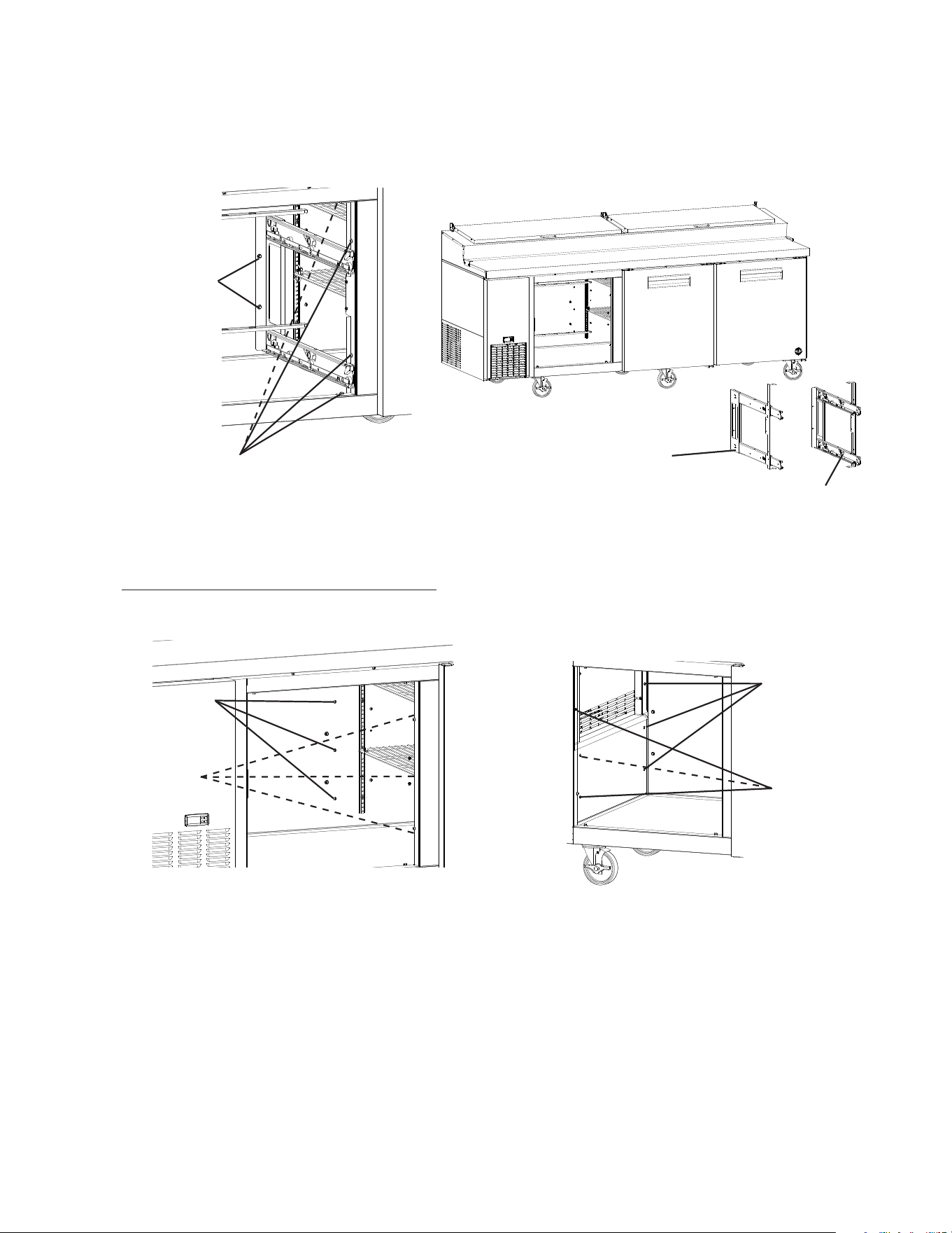
3) Attach the casters to the bottom of the appliance. Locking casters should be attached to
the front of the appliance. NOTICE! Do not place blocks under the refrigeration area
or doors/drawers of the appliance. Do not lay the appliance down.
a) PR46B(-D2): Attach all 6 casters. See Fig. 1. WARNING! On PR46B(-D2) models, all
6 casters must be installed. Otherwise, appliance may tip.
NOTICE! Ensure casters are completely threaded into the appliance and tight.
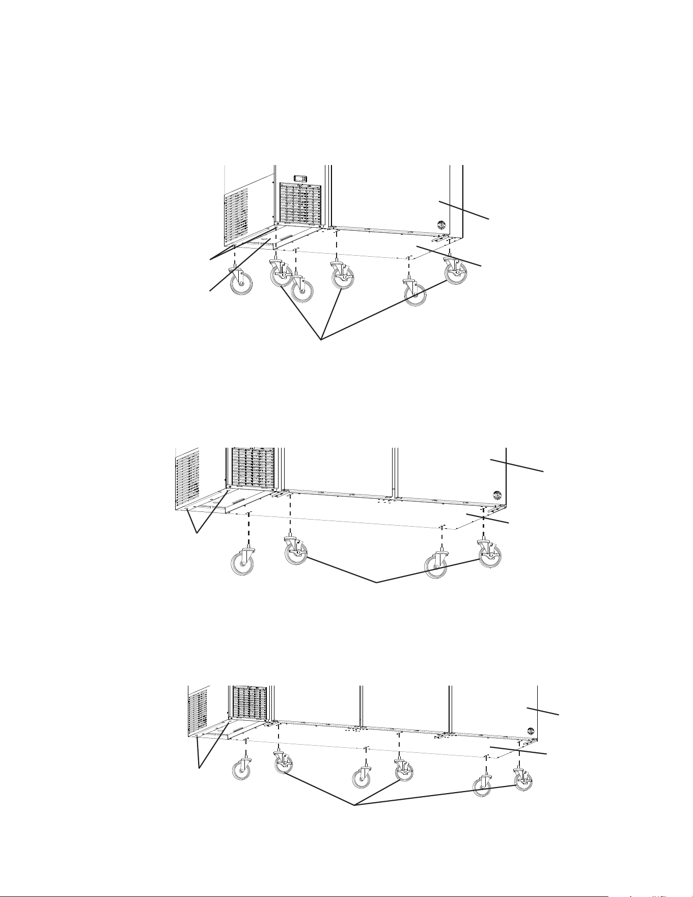
b) PR60B(-DX) and PR67B(-DX): Attach the 4 casters under the cabinet area.
See Fig. 2a. WARNING! On PR60B(-DX) and PR67B(-DX) models, do not attach
the casters under the compressor area in the outer left inserts.
NOTICE! Ensure casters are completely threaded into appliance and tight.
Fig. 2a
Door
Locking Casters in Front
Fig. 1
Fig. 2b
c) PR93B(-DX): Attach the 6 casters under the cabinet area. See Fig. 2b.
WARNING! On PR93B(-DX) models, do not attach the casters under the
compressor area in the outer left inserts. NOTICE! Ensure casters are
completely threaded into appliance and tight.
Model Shown: PR67B
Model Shown: PR46B
Locking Casters in Front
Door
Outer Left Inserts
Compressor Area
Model Shown: PR93B
Locking Casters in Front
Door
Cabinet Area
Cabinet Area
Cabinet Area
Outer Left Inserts
Outer Left Inserts
12
Fig. 3
Shelf
Support Clip
Pilaster
Shelves
2. Check the Refrigeration Circuit
Visually check that the refrigerant lines do not rub or touch other lines or surfaces and
that the condenser fan blade turns freely.
3. Position the Appliance and Lock the Front Casters
The front casters on the appliance are lockable. After positioning the appliance in its nal
location, lock the front casters.
4. Install the Shelves
1) For each shelf, place the shelf support clips into the pilasters at the desired height
(4 shelf support clips per shelf). See Fig. 3.
2) Place the shelves in position on the support clips.
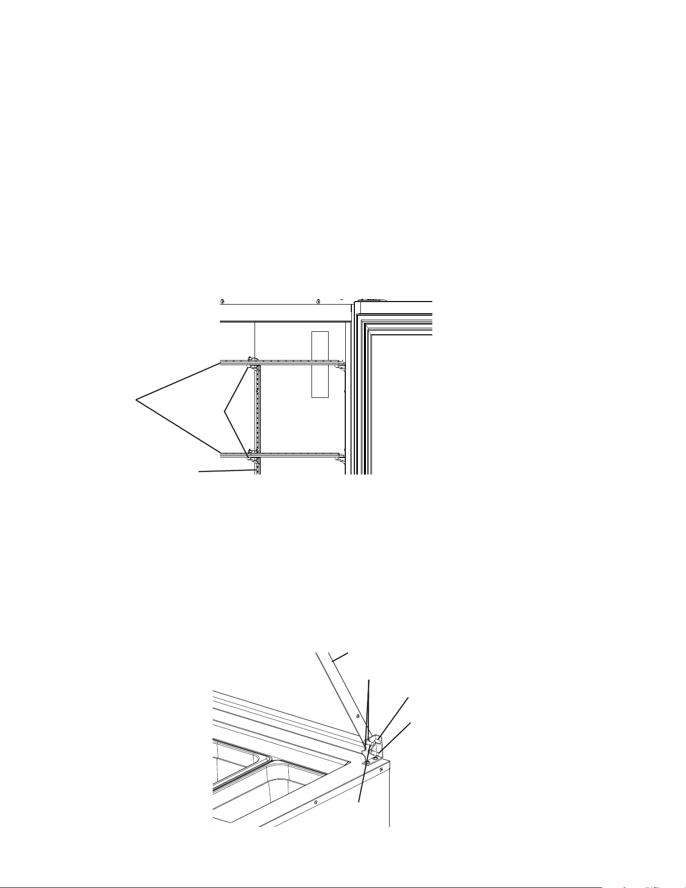
5. Conrm Rail Cover Operation
The rail cover's rear pins are inserted into the rear slots on both brackets. Use the rail
cover's front pins and the notches on the brackets to place the rail cover in the open
position. You can use either set of notches. The hollow side of the rail cover faces down.
See Fig. 4. WARNING! When the rail cover is open, make sure the rear pins on both
sides of the rail cover are securely in the rear slots and the front pins are resting
securely in the notches. Otherwise, the rail cover could close suddenly and cause
injury.
Fig. 4
Rear Pin
Rear Slot
Front Pin
Notches
Rail Cover
13
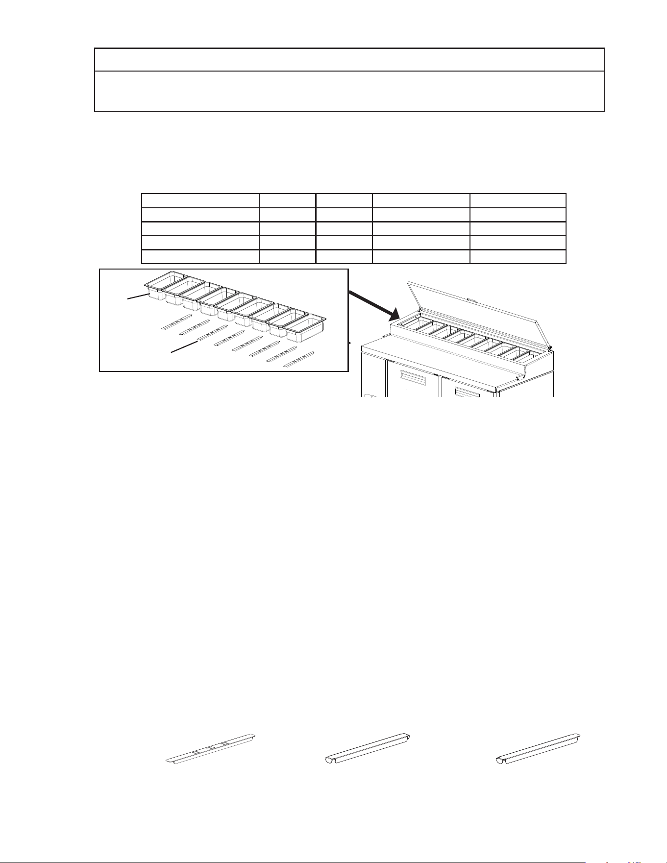
6. Properly Align Pans and Rail Dividers
NOTICE
The entire rail must be covered by rail dividers and pans (up to 6"(15cm)deep) to
avoid condensation issues and poor cooling performance.
Conrm rail dividers and pans are in place. See Fig.5. For pan size other than 1/3, see
"I.C.6.b) Alternative Pan Sizes" below.
a) Factory Shipped with 1/3 Size Pan and Front-to-Back Rail Dividers
Model Number Pan Size Pan Qty Rail Divider Rail Divider Qty
PR46B(-D2) 1/3 6 Front-to-Back 7
PR60B(-D4) 1/3 8 Front-to-Back 9
PR67B(-D2)(-D4) 1/3 9 Front-to-Back 10
PR93B(-D2)(-D4)(-D6) 1/3 12 Front-to-Back 13
1/3
Size
Pan
Front-to-Back
Rail Dividers
Fig. 5
• Wash the pans before use.
• The entire rail must always be covered by rail dividers and pans to avoid
condensation issues and poor cooling performance.
• Use only pans up to 6" (15 cm) deep. Do not use damaged rail dividers or pans.
• At startup, leave the pans empty and the rail covers closed until the appliance cools
down.
• An extra front-to-back rail divider is included. Use the extra front-to-back rail divider
if a gap remains after all pans and all other rail dividers are in place.
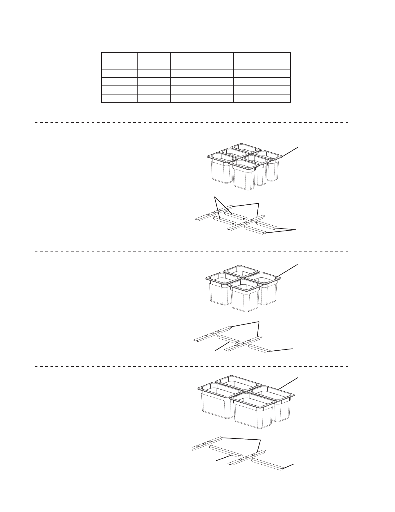
b) Alternative Pan Sizes:
For alternative pan sizes, additional center and outer side-to-side rail dividers are
required. See Fig. 6. NOTICE! The entire rail must be covered by rail dividers and
pans (up to 6" (15 cm) deep). Conrm all rail divider hooks are properly placed
into the front-to-back rail dividers and pans are level. Note: The extra front-to-
back rail divider provided with the appliance may be required in some pan size
combinations to assure that the rail area is fully covered.
Fig. 6
Front-to-Back Rail Divider
Center Side-to-Side Rail Divider
Outer Side-to-Side Rail Divider
Model Shown: PR67B
14
1/9 Pans and Rail Divider Conguration
1/6 Pans and Rail Divider Conguration
1/4 Pans and Rail Divider Conguration
1/3 Pans and Rail Divider Conguration
1/9 Pans and Rail Divider Conguration
1/6 Pans and Rail Divider Conguration
1/4 Pans and Rail Divider Conguration
1/3 Pans and Rail Divider Conguration
1/9 Pans and Rail Divider Conguration
1/6 Pans and Rail Divider Conguration
1/4 Pans and Rail Divider Conguration
1/3 Pans and Rail Divider Conguration
For alternative pan size combinations, see the table and examples in Figs. 7, 8, and 9
below.
HS Kit Pan Size Rail Divider Type Qty per Kit
HS-5534 All Sizes Front-to-Back 1
HS-5536 1/9 or 1/6 Outer Side-to-Side 1
HS-5535 1/4 Outer Side-to-Side 1
HS-5538 1/9 or 1/6 Center Side-to-Side 1
HS-5537 1/4 Center Side-to-Side 1
Note: Rail divider quantities vary depending on the pan size combination
1/9 Size Pan
Front-to-Back Rail Divider (HS-5534)
Center Side-to-Side Rail Divider (HS-5538)
Outer Side-to-Side Rail Divider (HS-5536)
1/9 Size Pan
1/6 Size Pan
1/4 Size Pan
Center Side-to-Side
Rail Divider
Center Side-to-Side
Rail Divider
Center Side-to-Side
Rail Divider
Front-to Back
Rail Divider
Front-to Back
Rail Divider
Front-to Back
Rail Divider
Outer Side-to-Side
Rail Divider
Outer Side-to-Side
Rail Divider
Outer Side-to-Side
Rail Divider
1/6 Size Pan
Front-to-Back Rail Divider (HS-5534)
Center Side-to-Side Rail Divider (HS-5538)
Outer Side-to-Side Rail Divider (HS-5536)
1/4 Size Pan
Front-to-Back Rail Divider (HS-5534)
Center Side-to-Side Rail Divider (HS-5537)
Outer Side-to-Side Rail Divider (HS-5535)
15
Fig. 10
Cutting Board Brackets
Cutting Board
Model Shown: PR67B
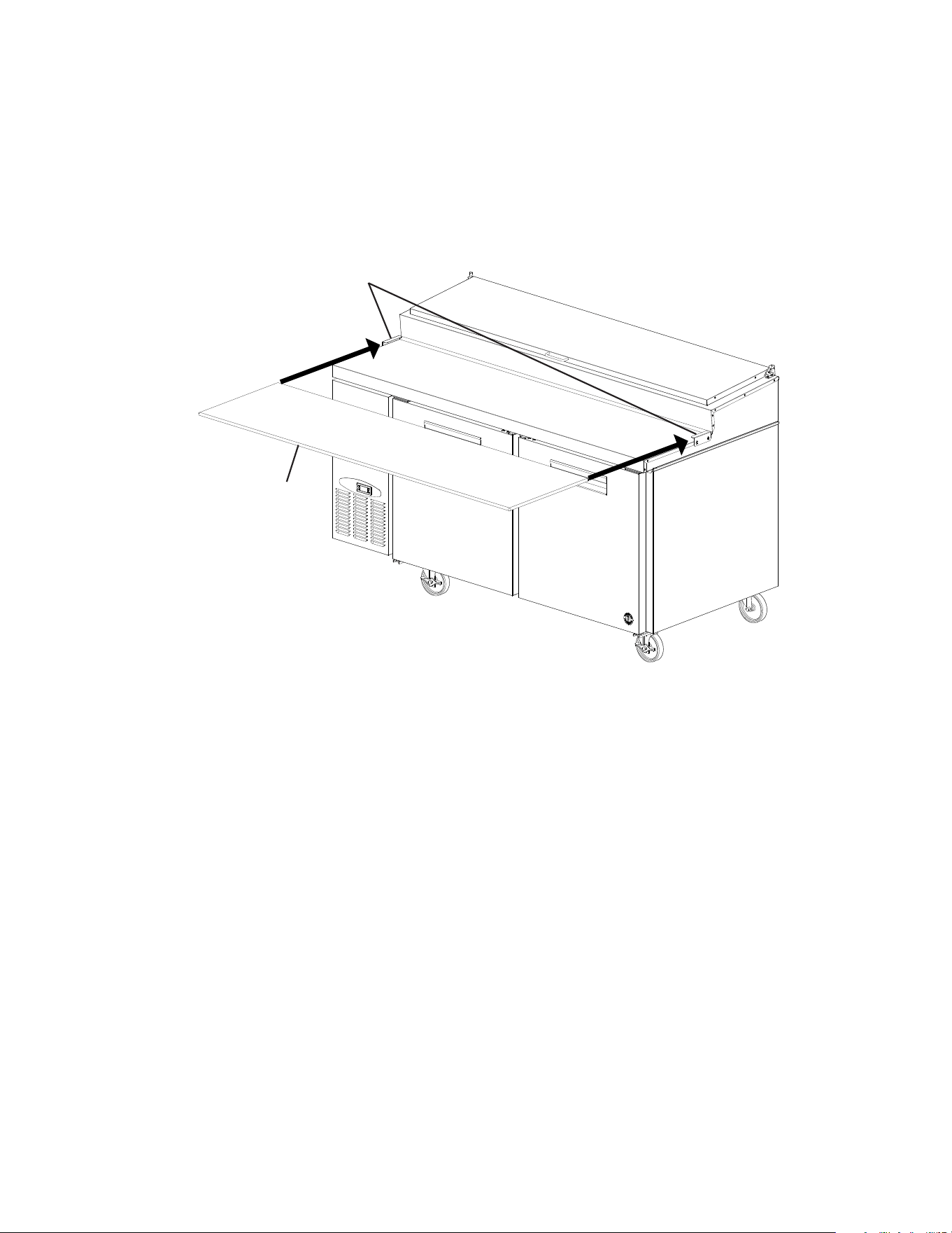
7. Attach the Cutting Board
1) Loosen, but do not remove, the screws securing the cutting board brackets. See Fig. 10.
2) Slide the cutting board under the cutting board brackets, then tighten the screws.
WARNING! Make sure the cutting board brackets and cutting board are secure.
Otherwise, the cutting board could come off and cause injury.
Note: Wash the cutting board before use.
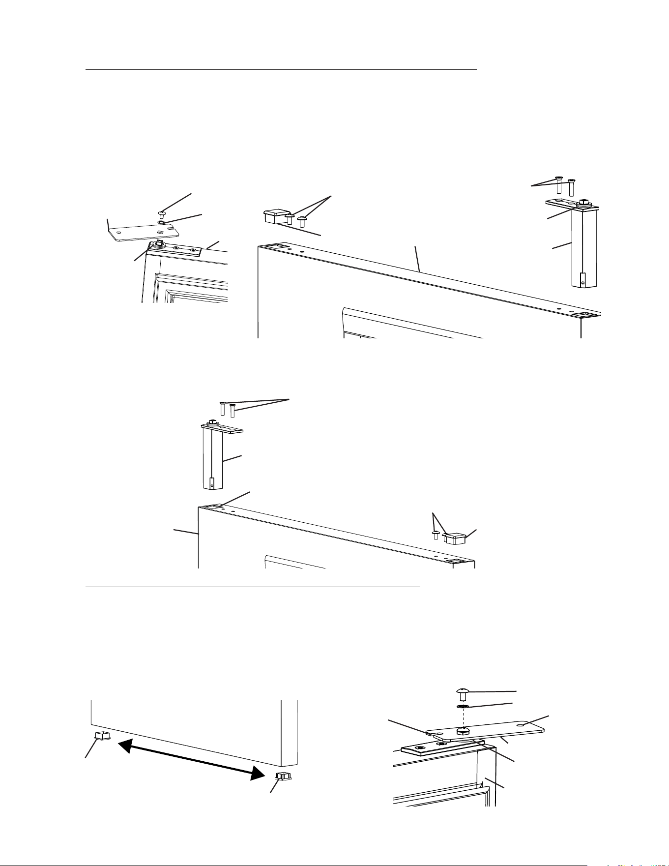
16
Lower Hinge Bracket
5) Remove the lower hinge bracket. See Fig. 13. Be sure to leave the thrust washer in
place.
6) Clear the foam from the lower hinge bracket mounting holes prior to securing lower
hinge bracket in its new location. Install the lower hinge bracket in its new location.
Be sure the lower hinge bracket is pushed all the way in and the thrustwasher is in its
original position. See Fig. 14.
Fig. 13
Bolts
Thrust
Washer
D. Door Reversal
The appliance is provided with a cabinet design which, after being delivered to the
installation location, permits changing of the door swing from left to right or right to left.
To change the door swing, follow the steps below. Example shows change from right
hinged to left hinged.
WARNING
• Wear proper PPE (personal protection equipment) when executing these
procedures (safety glasses and gloves).
• Keep ngers away from edge of upper hinge bracket. Spring cartridge can cause
the upper hinge bracket to move suddenly with extreme force.
Door and Lower Hinge Removal and Relocation
1) Remove all items from the appliance. Make sure the appliance is unplugged from the
electrical outlet. Move the appliance out for ease of access then lock the casters.
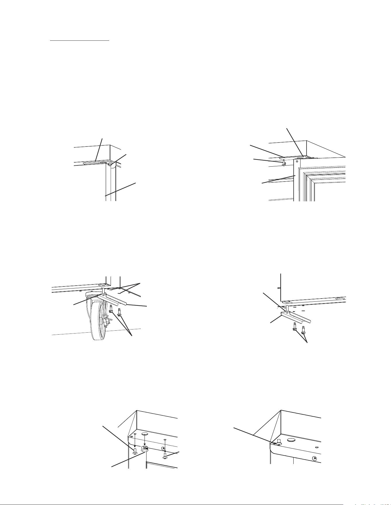
2) With the door closed, loosen, but do not remove, the upper hinge bracket outer screw.
See Fig. 11. Next, open the door to the fully open position and remove the upper hinge
bracket inner screw. See Fig. 12.
3) Slide the upper hinge bracket out from under the outer screw and remove the door.
WARNING! Keep away from upper hinge bracket. Upper hinge bracket may spring
closed.
4) Replace the upper hinge bracket inner screw in its original position and tighten, then
tighten the upper hinge bracket outer screw.
Fig. 11
Fig. 12
Upper Hinge
Bracket Inner
Screw
Door Fully Open
WARNING! Upper
hinge bracket may
spring closed
Lower Hinge Bracket
Bolts
Thrust Washer
Fig. 14
Upper Hinge Bracket
Outer Screw
Door Closed
Upper Hinge Bracket
Upper Hinge
Bracket
Lower Hinge
Bracket
Mounting Holes
17
Upper Hinge
Bracket
Door
Fig. 15
Screw
Washer
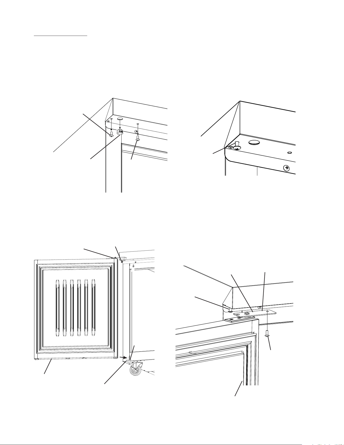
Upper Hinge Bracket Removal and Spring Cartridge Relocation
7) While preventing the upper hinge bracket from rotating, remove the upper hinge bracket
from the spring cartridge. See Fig. 15. Note which side of the upper hinge bracket is
facing up.
8) Remove the ller cap, ller screws, and spring cartridge. See Fig. 16. Leave the thrust
washers in place on the spring cartridge. NOTICE! Spring cartridge may be difficult
to remove. Be careful not to damage the nish.
Filler Cap
Door
Spring Cartridge
Filler Screws
Thrust Washers
Screws
Fig. 16
9) Clear foam from the spring cartridge hole to allow for spring cartridge installation.
See Fig. 17. Install the spring cartridge in its new location. Reinstall the ller cap and
ller screws on the opposite side of the door.
Filler Screws
Filler Cap
Door
Spring Cartridge
Screws
Fig. 17
Lower Door Prep and Upper Hinge Bracket Relocation
10) Remove the ller cap and nylon bearing from the bottom of the door. SeeFig.18.
Reinstall on the opposite side.
11) Make sure the thrust washers are in place on the spring cartridge, then ip the upper
hinge bracket over from its original position and install onto the spring cartridge in
the door open position. See Fig. 19. The upper hinge bracket should be positioned as
shown.
Upper Hinge Bracket
Inside of
Door
Screw
Washer
Fig. 18
Fig. 19
Filler Cap
Nylon Bearing
Thrust Washers
Upper Hinge
Bracket Inner
Screw Hole
Spring Cartridge Hole
Upper Hinge
Bracket Outer
Screw Slot
Thrust
Washers
18
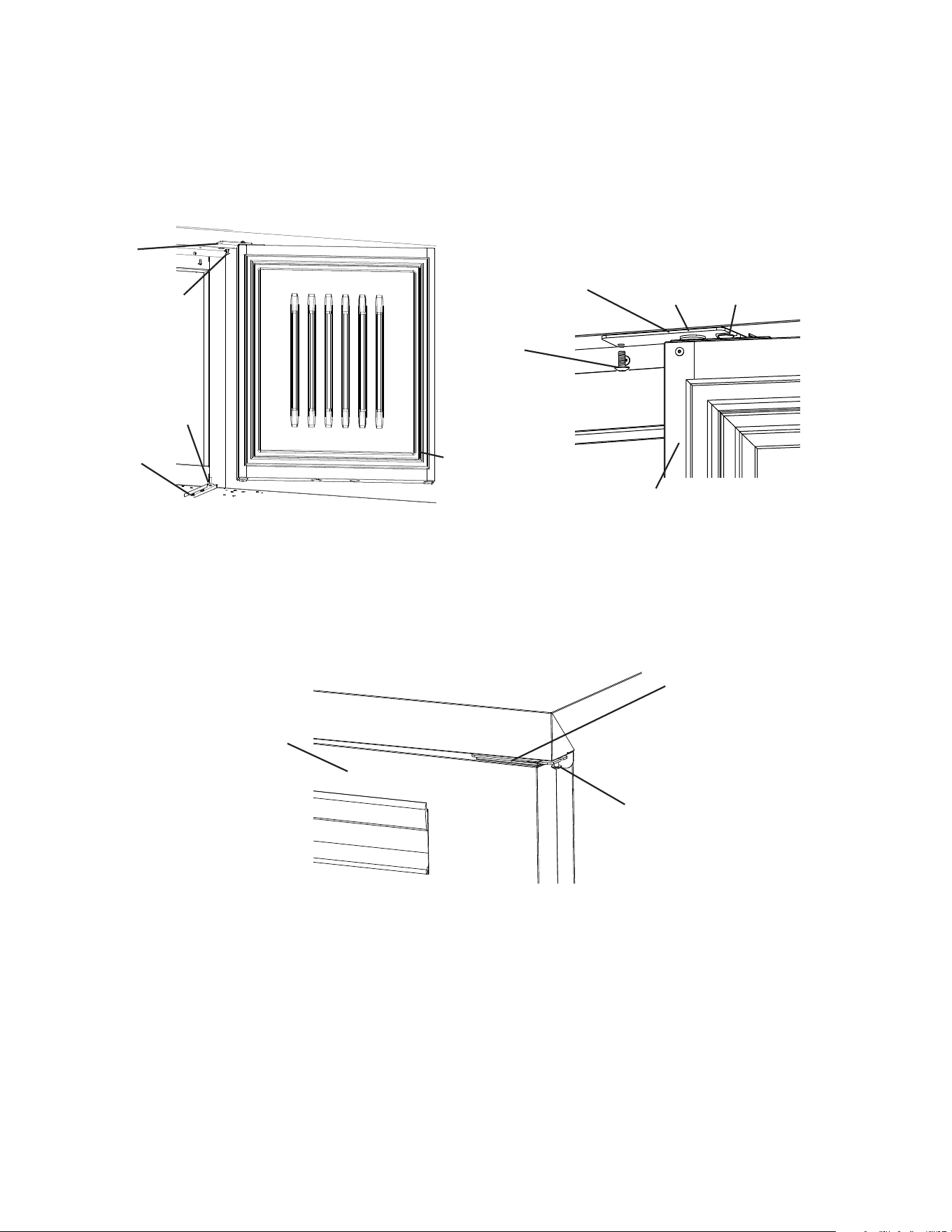
Door Installation
12) Remove the black plastic ller cap located from the hole above where the spring
cartridge screw will line up. Note: The black plastic ller cap is not reusable.
13) Remove the upper hinge bracket screws from the new location and apply Loctite
Threadlocker Blue 242 or 243 to the threads. Next, start the upper hinge bracket
outer screw into the appliance. Rotate a few threads into the appliance; do not tighten
thescrew. See Fig. 20.
14) Be sure the lower hinge bracket thrust washer is in place, then place the door on the
lower hinge bracket in the fully open position. Slide the door upper hinge bracket outer
slot onto the upper hinge bracket outer screw. See Fig. 21
15) Install the upper hinge bracket inner screw and tighten.
Fig. 20
Fig. 21
Door Fully Open
Lower Hinge Bracket
Upper Hinge Bracket
Outer Screw
Upper Hinge
Bracket Outer
Screw
Door Fully Open
Upper Hinge
Bracket
Upper Hinge
Bracket Inner
Screw
Upper Hinge Bracket
Outer Screw
Upper Hinge
Bracket Inner
Screw
Black Plastic Filler Cap
Upper Hinge
Bracket Outer
Screw
Upper Hinge
Bracket
WARNING! Upper
hinge bracket may
spring closed
Thrust
Washer
19
16) Close the door and tighten the upper hinge bracket outer screw.
See Fig. 22.
Fig. 22
Upper Hinge
Bracket
Upper Hinge Bracket
Outer Screw
17) Check the door operation to assure it opens and closes properly. Note: Hold door at
45°angle from closed position and release. Door should close on its own. If not, adjust
hinge bracket.
18) Unlock the casters and move the appliance back into its original position. Lock the
casters once in position, then plug the appliance back into the electrical outlet. Allow the
appliance to cool down prior to putting product back in.
Door Fully Closed
20
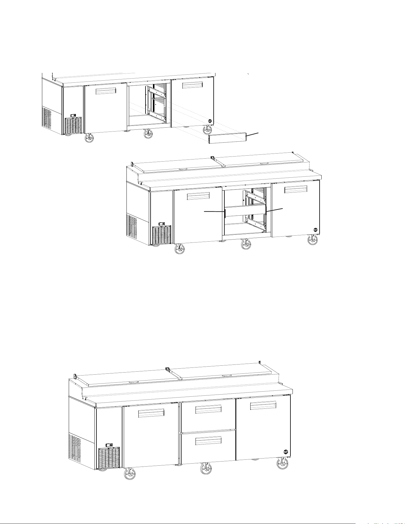
3) Remove the 4 mullion screws, then cut the front mullion silicone loose and remove the
mullion. See Fig. 24.
Fig. 24
Mullion Screws
Mullion Silicone
Mullion Silicone
Mullion
E. Door/Drawer Reversal
The appliance is provided with a cabinet design which, after being delivered to the
installation location, permits changing of the drawer and door locations. To change the
drawer and door locations, follow the steps below.
WARNING
• Wear proper PPE (personal protection equipment) when executing these
procedures (safety glasses and gloves).
• Keep ngers away from edge of upper hinge bracket. Spring cartridge can cause
the upper hinge bracket to move suddenly with extreme force.
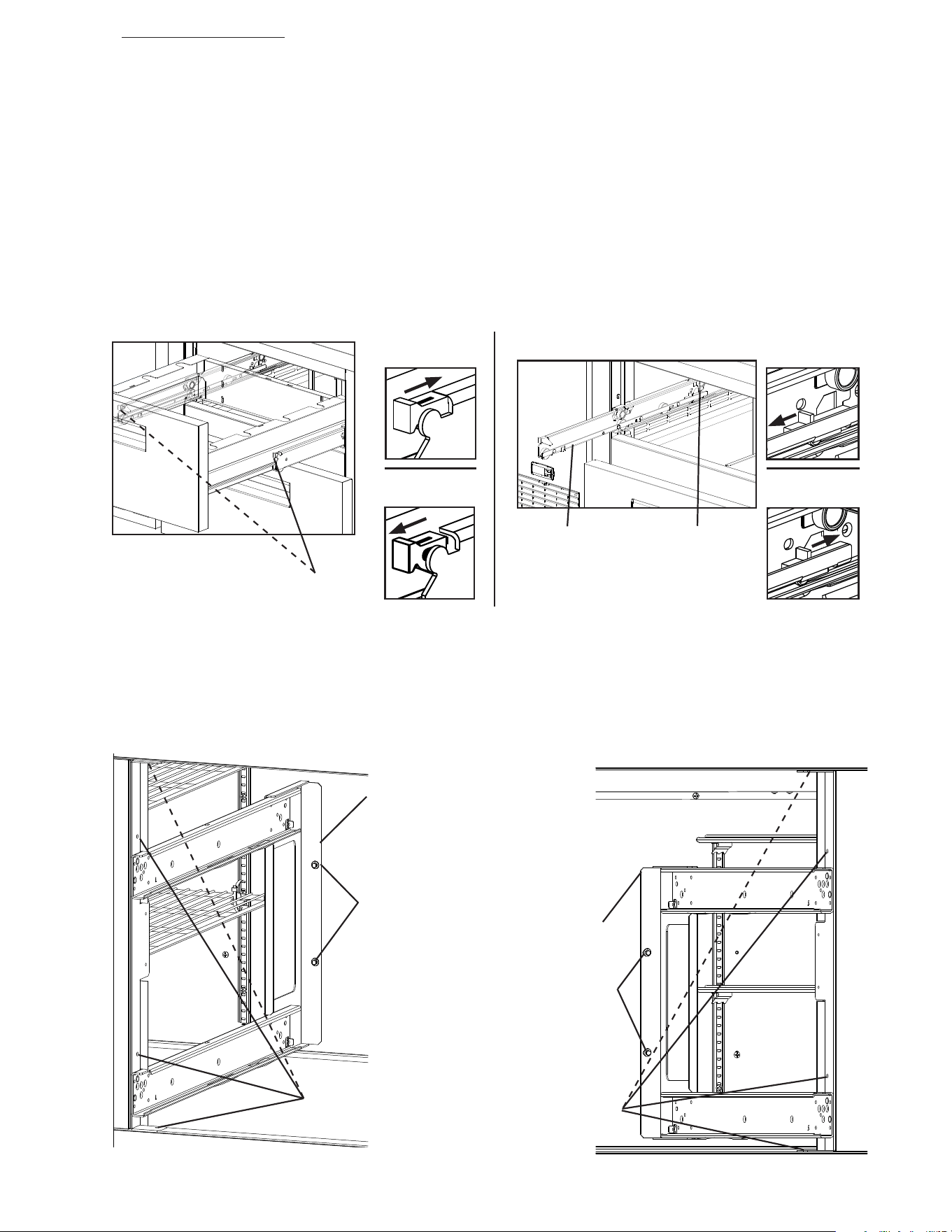
Drawer and Drawer Cartridge Removal
1) Remove all items from the appliance. Make sure the appliance is unplugged from the
electrical outlet. Move the appliance out for ease of access then lock the casters.
See Fig. 23.
2) Remove the drawers. Pull the drawer out to its fully extended position. Open the safety
clips (one on each side) by sliding them forward. Lift up slightly and remove them from
the drawer cartridge. See. "III.A.6. Drawers" for reference. Be sure to note which is the
upper drawer and which is the lower drawer.
Fig. 23
Upper Drawer
Lower Drawer
Drawer
Cartridge
Casters
21
4) Remove the 4 rear screws from the left and right drawer cartridge frames
(2 per side). See Fig. 25.
5) Remove the 8 front screws from the left and right drawer cartridge frames (4 per side),
then remove the cartridge frames from the unit.
Pilaster and Filler Screw Relocation
6) Remove the 12 pilaster ller screws from the current drawer section. See Fig. 26.
Fig. 25
Fig. 26
Rear Pilaster
Filler Screws
Rear Screws
Front Screws
Left Drawer
Cartridge Frame
Right Drawer
Cartridge Frame
Front Pilaster
Filler Screws
Rear Pilaster
Filler Screws
Front Pilaster
Filler Screws
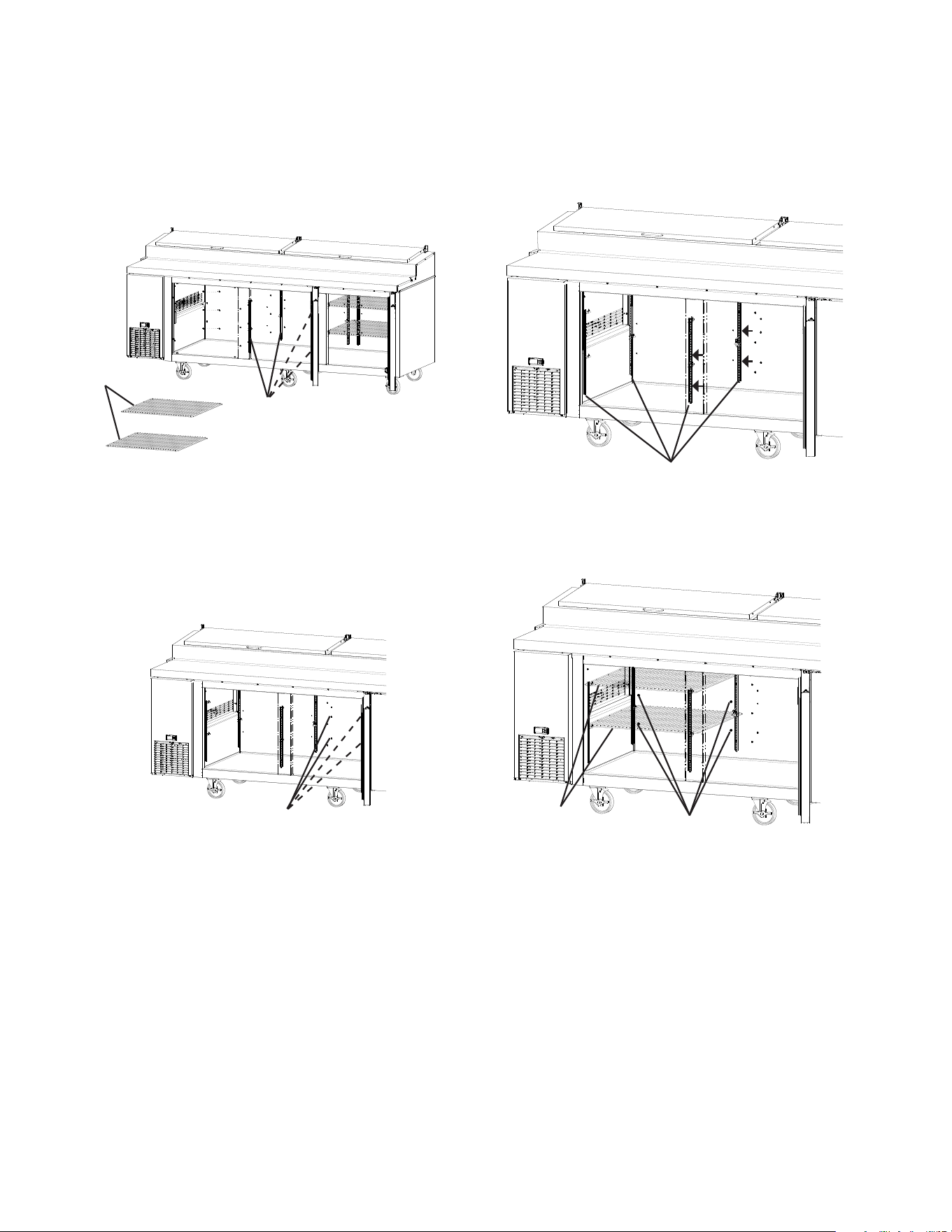
22
7) Remove the shelves from the door section, then remove the pilasters and place and
secure them in the new location (current drawer location). See Fig. 27. Note: Other than
in a center location, outer pilasters mount on the side wall not the rear wall.
8) Place and secure the pilaster ller screws removed in step 6 into the new drawer
location (current door location).
Shelves
Pilasters
Pilasters
9) Remove the drawer cartridge frame rear ller screws from the new location (current
door location). Place the drawer cartridge frame ller screws in the new door location
and tighten. Replace the shelves. See Fig. 28.
Fig. 27
Rear Filler
Screws
Shelves
Rear Filler
Screws
Fig. 28
23
Door Relocation
10) With the door closed, loosen, but do not remove, the upper hinge bracket outer screw.
See Fig. 29. Next, open the door to the fully open position and remove the upper hinge
bracket inner screw. See Fig. 30.
11) Slide the upper hinge bracket out from under the outer screw and remove the door.
WARNING! Keep away from upper hinge bracket. Upper hinge bracket may spring
closed.
12) Replace the upper hinge bracket inner screw in its original position and tighten, then
tighten the upper hinge bracket outer screw.
Upper Hinge
Bracket Outer
Screw
Door Closed
Upper Hinge
Bracket Inner
Screw
Door Fully Open
WARNING! Upper
hinge bracket may
spring closed
13) Remove the lower hinge bracket. See Fig. 31. Be sure to leave the thrust washer in
place.
14) Clear the foam from the lower hinge bracket mounting holes prior to securing the lower
hinge bracket in its new location. Install the lower hinge bracket in its new location. Be
sure the lower hinge bracket is pushed all the way in and the thrust washer is in its
original position.
Lower Hinge Bracket
Bolts
Thrust
Washer
Lower Hinge Bracket
Bolts
Thrust Washer
15) Remove the black plastic ller cap located from the hole above where the spring
cartridge screw will line up. Note: The black plastic ller cap is not reusable.
16) Remove the upper hinge bracket screws from the new location and apply Loctite
Threadlocker Blue 242 or 243 to the threads. Next, start the upper hinge bracket
outer screw into the appliance. Rotate a few threads into the appliance; do not tighten
thescrew. See Fig. 32.
Fig. 29
Fig. 31
Fig. 32
Upper Hinge Bracket
Upper Hinge Bracket
Upper Hinge Bracket
Outer Screw
Upper Hinge
Bracket Inner
Screw
Black Plastic Filler Cap
Upper Hinge
Bracket Outer
Screw
Fig. 30
Lower Hinge
Bracket
Mounting Holes
24
17) Be sure the lower hinge bracket thrust washer is in place, then place the door on the
lower hinge bracket in the fully open position. Slide the door upper hinge bracket outer
slot onto the upper hinge bracket outer screw. See Fig. 33.
18) Install the upper hinge bracket inner screw and tighten.
Upper Hinge
Bracket Inner
Screw
Door Fully Open
WARNING! Upper
hinge bracket may
spring closed
19) Close the door and tighten the upper hinge bracket outer screw. See Fig. 34.
Fig. 33
Upper Hinge
Bracket Outer
Screw
Upper Hinge
Bracket Outer
Screw
Door Fully
Open
Lower Hinge
Bracket
Upper Hinge
Bracket
Thrust Washer
Upper Hinge
Bracket
20) Check the door operation to assure it opens and closes properly. Note: Hold door at
45°angle from closed position and release. Door should close on its own. If not, adjust
hinge bracket.
Upper Hinge Bracket
Outer Screw
Upper Hinge Bracket
Door Fully Closed
Fig. 34
25
Left Drawer
Cartridge Frame
Front Screws
Rear Screws
Fig. 37
Right Drawer
Cartridge Frame
Front Screws
Rear Screws
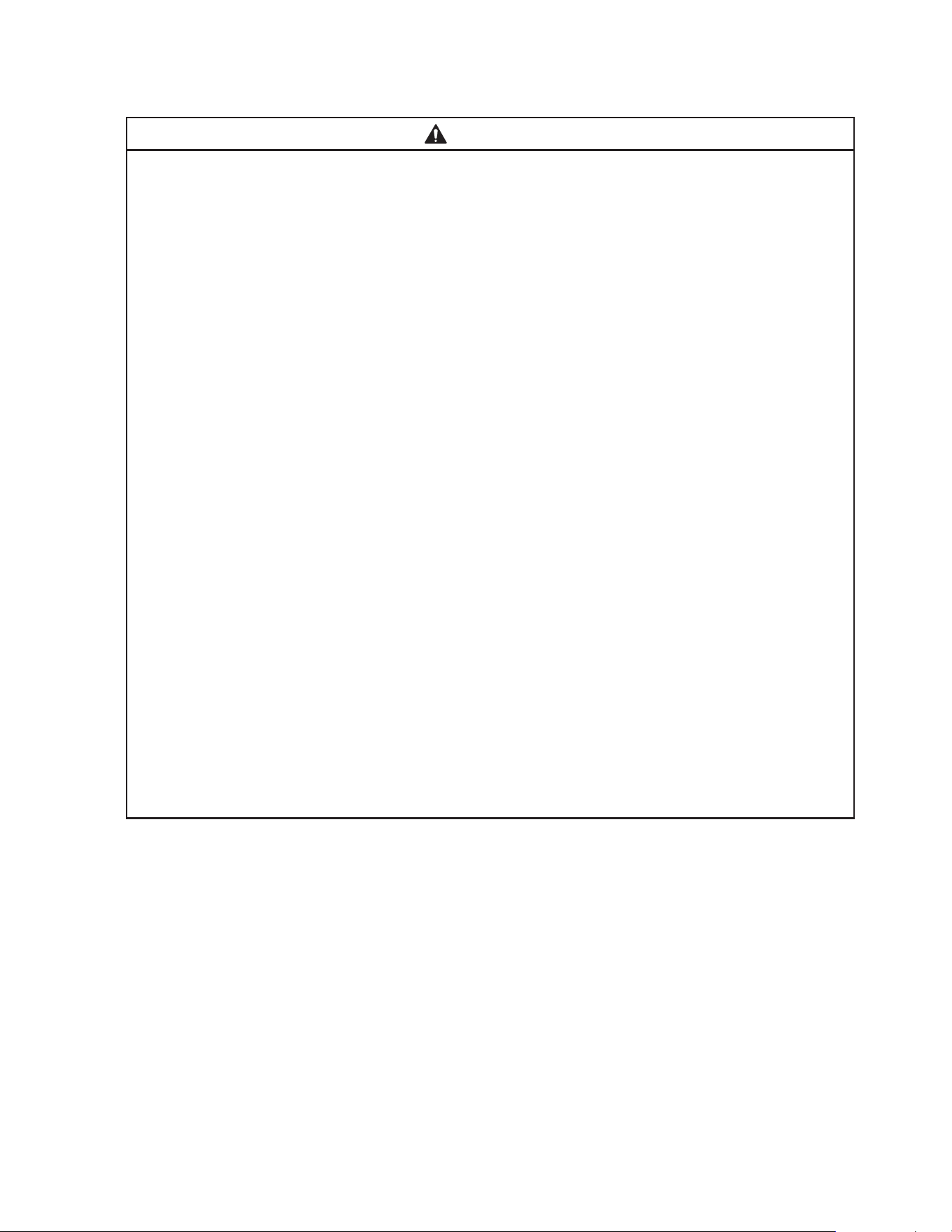
Drawer Relocation
Drawers and drawer slides are removable.
• To remove a drawer: Remove all items from the drawer. Pull the drawer out to its fully
extended position. Open the safety clips (one on each side) by sliding them forward.
See Fig. 35. Lift up on the handle slightly, then pull to disengage the drawer. Be sure
to support the rear and front of the drawer while removing it. WARNING! Be sure to
close the safety clips when reinstalling the drawer.
• To remove a drawer slide (center slide containing rollers): Open the stop levers
(one on each side) by sliding them to the rear. See Fig. 36. Lift up on the drawer slide
slightly, then pull to disengage the drawer slide. WARNING! Be sure to close the stop
levers when reinstalling the drawer. Drawer slides do not require lubrication, but
drawer slides should be kept clean and free of food.
Note: Drawer slides are dishwasher safe.
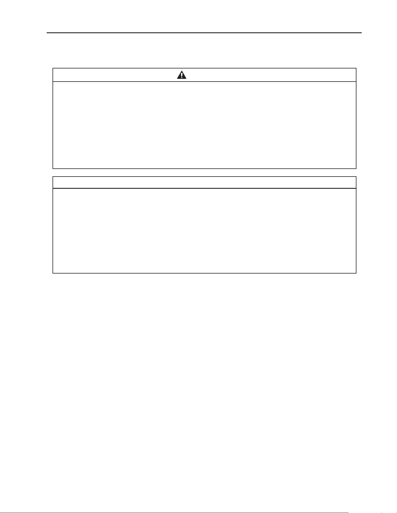
21) Place a drawer cartridge frame in place and secure to the rear panel with screws
removed in step 4. See Fig. 37.
22) Using a 1/8" drill bit, drill pilot holes in all 4 front mounting holes.
23) Secure the drawer cartridge to the appliance with the screws removed in step 5.
24) Repeat steps 21 through 23 for the opposite side drawer cartridge frame.
Fig. 35
Safety Clips
Safety Clip
Closed
Fig. 36
Safety Clip
Open
Stop Lever
Drawer Slide
Stop Lever
Closed
Stop Lever
Open
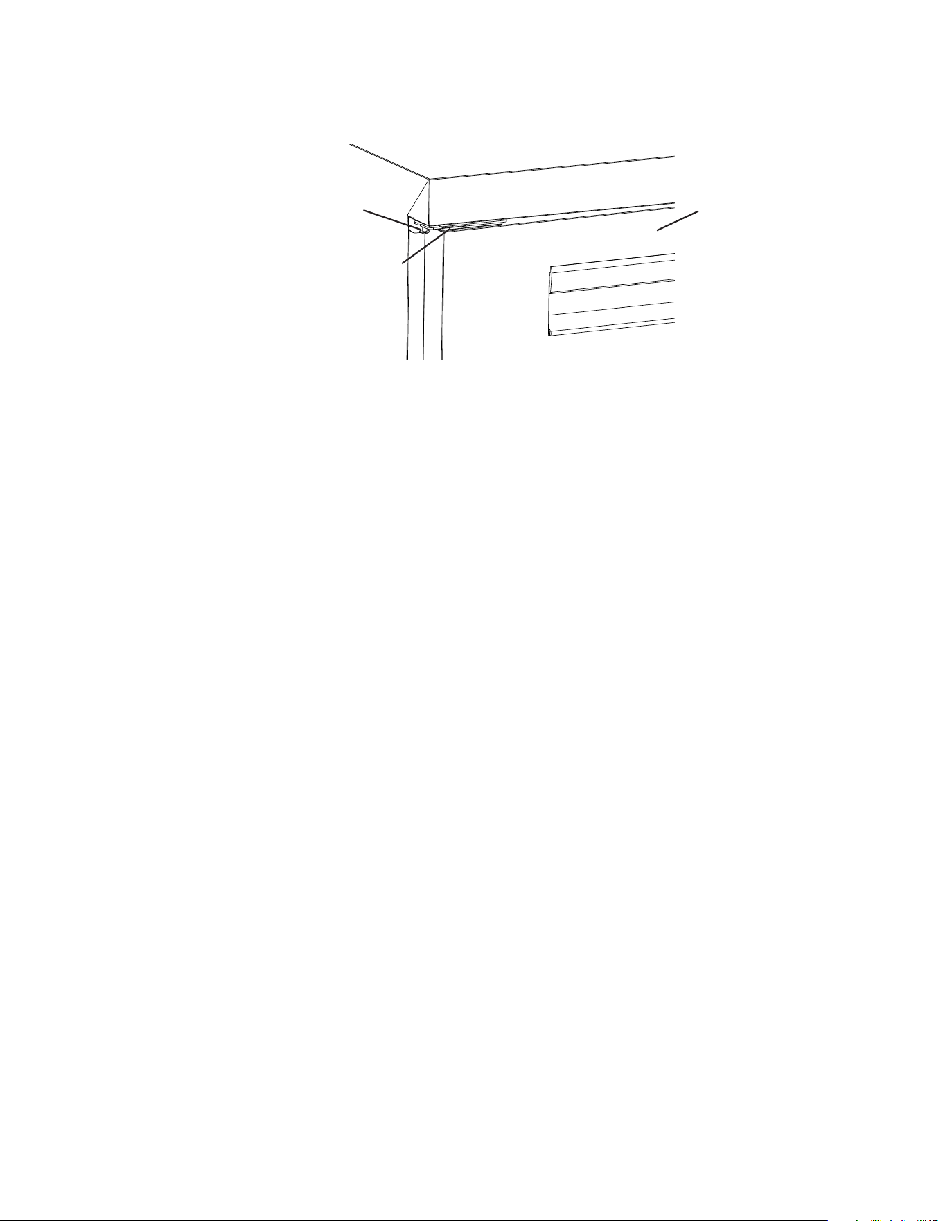
26
25) Place the mullion in its correct position and secure with screws removed in step3.
26) Place a bead of food grade silicone down the 2 outside vertical gaps between the
mullion and appliance. See Fig. 38.
Fig. 38
Mullion
Silicone
Location for
Mullion
Silicone
Location for
Mullion
27) Place the lower drawer in the lower drawer slides and the upper drawer in the upper
drawer slides. See Fig. 39. WARNING! Be sure to close the safety clips when
reinstalling the drawer.
28) Make sure all gaskets are making good contact. Using a ashlight, check that there are
no openings around all gaskets.
29) Unlock the casters and move the appliance back into its original position. Lock the
casters once in position, then plug the appliance back into the electrical outlet. Allow the
appliance to cool down prior to putting product back in.
Fig. 39
27
F. Electrical Connection
WARNING
• Electrical connection must meet national, state, and local electrical code
requirements. Failure to meet these code requirements could result in death,
electric shock, serious injury, re, or severe damage to equipment.
• The appliance requires an independent power supply of proper capacity.
See the nameplate for electrical specications. Failure to use an independent
power supply of proper capacity can result in a tripped breaker, blown fuse,
damage to existing wiring, or component failure. This could lead to heat
generation or re.
• THE APPLIANCE MUST BE GROUNDED. The appliance is equipped with a
NEMA5-15 three-prong grounding plug to reduce the risk of potential shock
hazards. It must be plugged into a properly grounded, independent 3-prong wall
outlet. If the outlet is a 2-prong outlet, it is your personal responsibility to have
a qualied electrician replace it with a properly grounded, independent 3-prong
wall outlet. Do not remove the ground prong from the power cord and do not use
an adapter plug. Failure to follow these instructions may result in death, electric
shock, or re.
• To reduce the risk of electric shock, do not touch the plug with damp hands.
• Do not use an extension cord.
• Do not use an appliance with a damaged power cord. The power cord should not
be altered, jerked, bundled, weighed down, pinched, or tangled. Such actions
could result in electric shock or re. To unplug the appliance, be sure to pull the
plug, not the cord, and do not jerk the cord.
• The GREEN ground wire in the factory-installed power cord is connected to the
appliance. If it becomes necessary to remove or replace the power cord, be sure
to connect the power cord's ground wire.
• Usually an electrical permit and services of a licensed electrician are required.
• The maximum allowable voltage variation is ±10 percent of the nameplate rating.

28
G. Final Checklist
1) Is the appliance level?
2) Have the casters been properly installed and have the front casters been locked?
3) Is the appliance in a site where the ambient temperature is constantly within 45°F to 86°F
(7°C to 30°C)?
4) Have the shipping carton, tape, and packing material been removed from the appliance?
Has the protective plastic lm been removed from both the exterior panels and the
interior door/drawer panel?
5) Have the appliance and accessories been checked for shipping damage?
6) Is there at least 1" (3 cm) clearance at sides for proper air circulation? Are the
factory-installed rear bumpers in place to ensure proper rear clearance? Is there at least
10" (25 cm) clearance above the rail to allow the rail cover to open?
7) Have the pans, rail dividers, and cutting board (cutting board brackets) been cleaned
and properly installed? Have any gaps in the rail area been properly addressed with rail
dividers?
8) Has the power supply voltage been checked or tested against the nameplate rating?
Is the power supply a properly grounded, independent wall outlet? Does the electrical
connection meet all national, state, and local code and regulation requirements.
9) Have the refrigerant lines been checked to make sure they do not rub or touch other lines
or surfaces? Has the condenser fan blade been checked to make sure it turns freely?
Is the compressor securely attached?
10) Have the shelves been adjusted to the desired height?
11) Has the end user been given the instruction manual, and instructed on how to operate
the appliance and the importance of the recommended periodic maintenance?
12) Has the end user been given the name and telephone number of an authorized service
agent?
13) Has the warranty card been lled out and forwarded to the factory for warranty
registration?
29
II. Operating Instructions
A. Important Notes About Usage
DANGER
Risk of Fire or Explosion
Flammable Refrigerant Used
• Do not use mechanical devices to defrost.
• Do not puncture refrigerant tubing. Risk
of re or explosion due to puncture
of refrigerant tubing; follow handling
instructions carefully.
• Do not place any potential ignition sources
in or near the appliance.
Risque De Feu Ou D'Explosion
Le Frigorigène Est Inammable
• Ne pas utiliser d'appareils mécaniques
pour dégivrer le réfrigérateur.
• Ne pas perforer la tubulure contenant le
frigorigène. Risque de feu ou d'explosion
si la tubulure contenant le frigorigène
est perforée; suivre les instructions de
manutention avec soin.
• Ne placez aucune source d’inammation
potentielle dans ou près de l’appareil.
• The appliance is not intended for use by
persons (including children) with reduced
physical, sensory, or mental capabilities,
or lack of experience and knowledge,
unless they have been given supervision
or instruction concerning use of the
appliance by a person responsible for
their safety.
• Children should be properly supervised
around the appliance.
• Do not climb, stand, or hang on the
appliance or doors/drawers or allow
children or animals to do so. Do not climb
into the appliance or allow children or
animals to do so. Death or serious injury
could occur or the appliance could be
damaged.
• Be careful not to pinch ngers when
opening and closing the doors/drawers
or rail cover or when handling food pans.
Be careful when opening and closing the
doors/drawers or rail cover when children
are in the area.
• Open and close the doors/drawers and
rail cover with care. Opening the doors/
drawers or rail cover too quickly or
forcefully may cause injury or damage to
the appliance or surrounding equipment.
• Do not use combustible spray or place
volatile or ammable substances in or
near the appliance. They might catch re.
• Keep the area around the appliance clean.
Dirt, dust, or insects in the appliance
could cause harm to individuals or
damage to the equipment.
• Do not throw anything onto the shelves
or load any single shelf with more than
120lb. (54.5 kg) of product. They might fall
off and cause injury.
• Do not load any single drawer with more
than 75 lb. (34 kg) of product. Depending
on the weight of product in the drawers,
secure the unit as necessary to prevent it
from overturning. Do not open more than
one drawer at a time.
WARNING
• Only qualied service technicians should
install and service the appliance.
• Wear appropriate personal protective
equipment (PPE) when servicing the
appliance.
• Failure to install, operate, and maintain
the appliance in accordance with this
manual may adversely affect safety,
performance, component life, and
warranty coverage.
• To reduce the risk of electric shock, do
not touch the plug with damp hands.
• Do not splash, pour, or spray water
directly onto or into the appliance. This
might cause short circuit, electric shock,
corrosion, or failure.
30
WARNING, continued
• The appliance is designed only for
temporary storage of food. Employ
sanitary methods. Use for any other
purposes (for example, storage of
chemicals or medical supplies such
as vaccine and serum) could cause
deterioration of stored items.
• Do not block air inlets or outlets, otherwise
cooling performance may be reduced.
• Do not tightly pack the cabinet. Allow
some space between items to ensure
good air ow. Also allow space between
items and interior surfaces.
• Do not put warm or hot foods in the
cabinet. Let them cool rst, or they will
raise the cabinet temperature and could
deteriorate other foods in the cabinet or
overload the appliance.
• Food storage and handling must comply
with applicable codes and regulations.
• All foods should be wrapped in plastic
lm or stored in sealed containers.
Otherwise foods may dry up, pass their
smells onto other foods, cause frost
to develop, result in poor appliance
performance, or increase the likelihood of
cross-contamination. Certain dressings
and food ingredients, if not stored in
sealed containers, may accelerate
corrosion of the evaporator, resulting in
failure.
• Do not store items near air outlets.
Otherwise, items may freeze up and
crack or break causing a risk of injury or
contamination of other food.
• The entire rail must always be covered
by rail dividers and pans. Otherwise, the
appliance will not cool properly. Use only
pans up to 6"(15cm) deep. Do not use
damaged rail dividers or pans. For rail
divider and pan combinations, see "I.C.6.
Properly Align Pans and Rail Dividers."
• Ingredients must be pre-chilled to 37°F
(3°C) or less before placing in rail.
• Keep the rail cover closed when not
actively preparing food.
• The rail is for keeping ingredients cool
while preparing food. If not actively
preparing food for a long period such as
overnight, seal pans with plastic wrap in
addition to closing the rail cover.
• During daytime operation with the rail
cover(s) open, do not block the rail light
sensor. Blocking the rail light sensor
initiates night mode operation. For details,
see "II.C. Control and Adjustments."

31
NOTICE
• Protect the oor when moving the
appliance to prevent damage to the oor.
• Keep ventilation openings clear of
obstruction.
• The factory-installed rear bumpers
must be in place to ensure proper rear
clearance. Blockage of airow could
negatively affect performance and
damage the appliance.
• Do not allow the appliance to bear any
outside weight.
• To prevent deformation or cracks, do not
spray insecticide onto the plastic parts or
let them come into contact with oil.
• To avoid damage to the gasket, use only
the door/drawer handle when opening
and closing.
• Do not leave the doors/drawers open.
• To avoid damage to the top seal, do not
lift the appliance by the top section or
remove the top section.
• Do not place anything on top of the rail
cover. The rail cover is not designed to
bear any outside weight.
• Do not place anything on the air duct
panels beneath the pans in the rail.
The air duct panels are not load-bearing.
• A minimum of 10"(25cm) clearance
above the rail should be provided to allow
the rail cover to open.
32
2. Startup:
5) Plug the appliance into the electrical outlet. WARNING! To reduce the risk of electric
shock, do not touch the plug with damp hands. At startup, there is a slight delay
before the compressor starts.
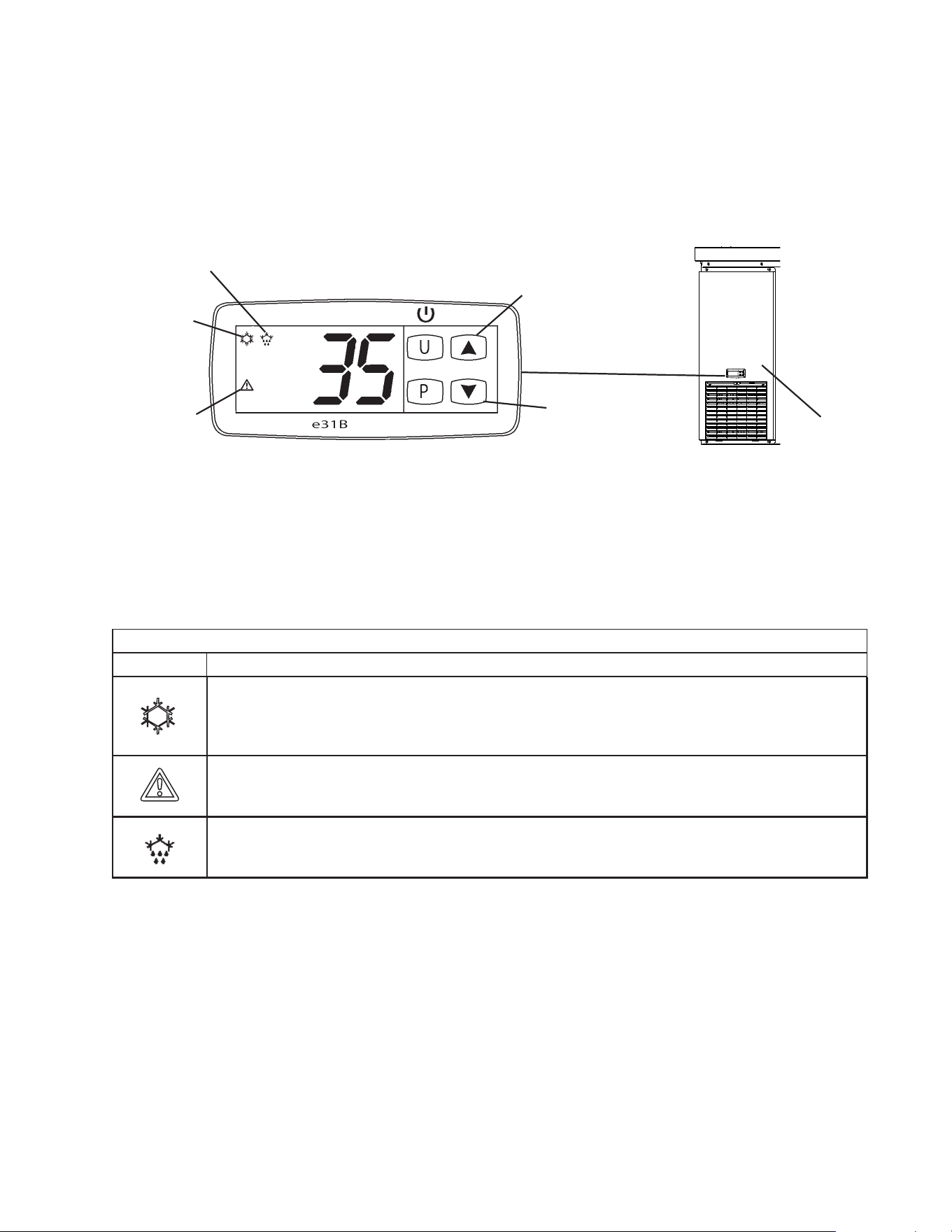
6) Conrm the cabinet control setpoint is 35°F (1.7°C) on
the cabinet control module located on the front panel. See
Fig. 41. To conrm the setpoint, press the up arrow key
for 2 seconds and release. The setpoint ashes. If not set
to 35°F (1.7°C), see "II.C.2 Cabinet Temperature Control"
below. NOTICE! Cabinet temperature control does not
control compressor operation. Only cabinet fan motor
operation. For compressor operation control see "II.C.
Rail Control Dial Adjustment."
7) Allow the appliance to cool down prior to loading it with food
products. Conrm all rail dividers and pans are in place.
B. Pre-Startup and Startup
WARNING
All parts are factory-adjusted. Improper adjustments may adversely affect safety,
performance, component life, and warranty coverage.
1. Pre-Startup:
1) Wash the pans and cutting board before use.
2) Conrm all pans and rail dividers are in place. Do not leave any gap between pans or
appliance. Close the rail cover(s). NOTICE! The entire rail must be covered by rail
dividers and pans (up to 6"(15cm)deep)) and the rail cover must be closed at
startup. Otherwise, the appliance will not cool down properly. See "I.C.6. Pans
and Rail Dividers" for details. Leave the pans empty until the appliance cools down.
WARNING! When the rail cover is open, make sure the rear pins on both sides of
the rail cover are securely in the rear slots and the front pins are resting securely
in the notches. Otherwise, the rail cover could close suddenly and cause injury.
3) If not already installed, install the cutting board. See "I.C.7. Attach the Cutting Board" for
details. WARNING! Make sure the cutting board brackets and cutting board are
secure. Otherwise, the cutting board could come off and cause injury.
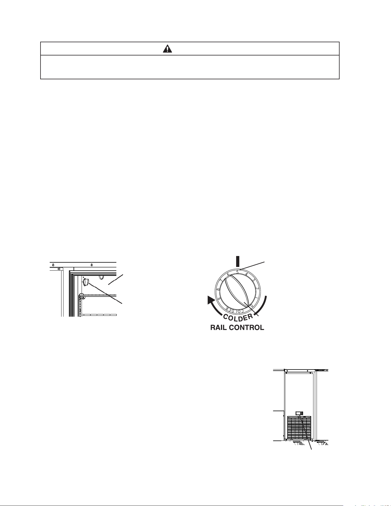
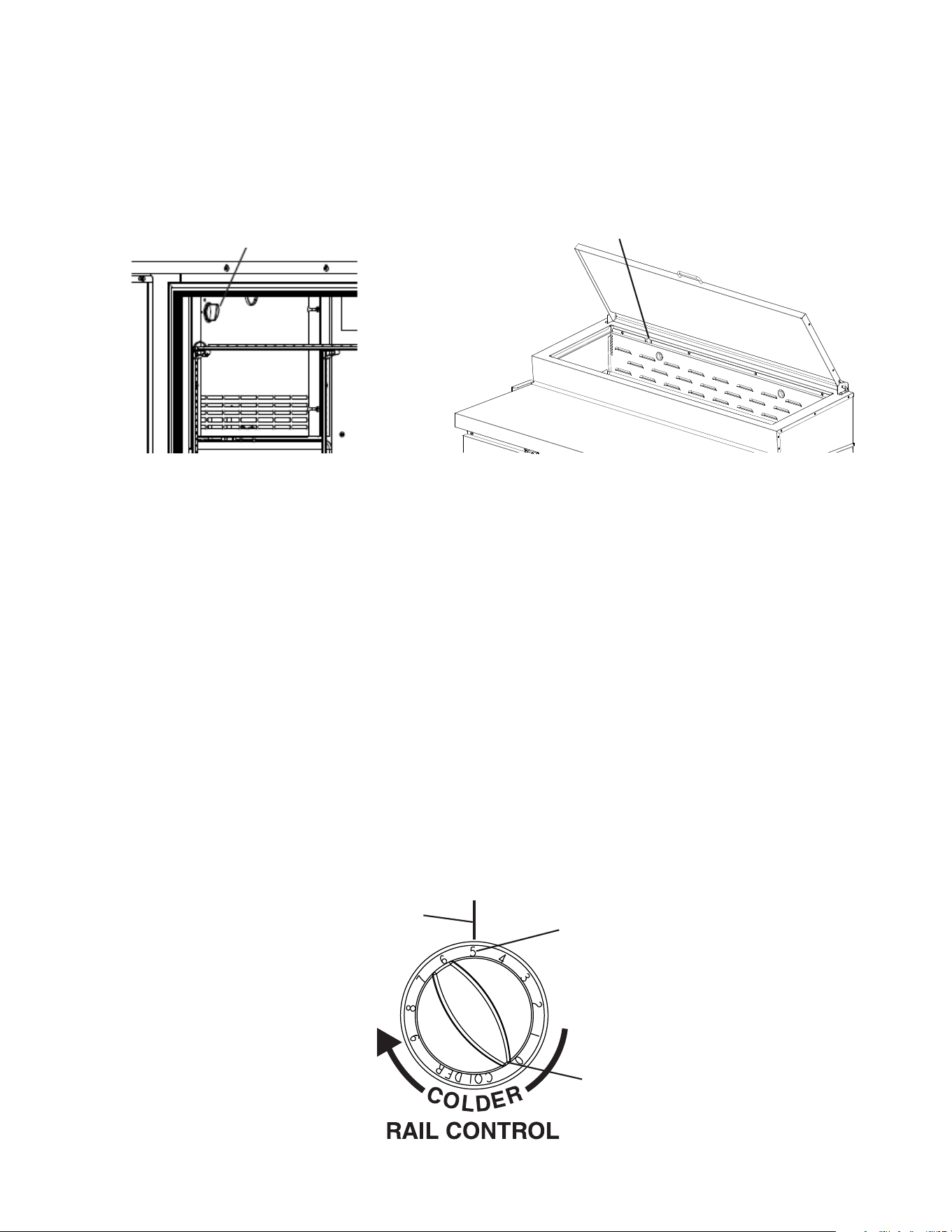
4) Locate the rail control dial inside the cabinet and conrm the rail control dial is set to 5.
See Fig. 40. The rail control dial is located on the left side wall of the cabinet interior.
Factory Default: 5 (27°F (-2.8°C)).
Cabinet Control Module
Fig. 40
Fig. 41
Left Side Wall of
Cabinet Interior
Rail Control Dial
12 o'clock Setpoint Position
Setpoint Position 5
Rail Control Dial
33
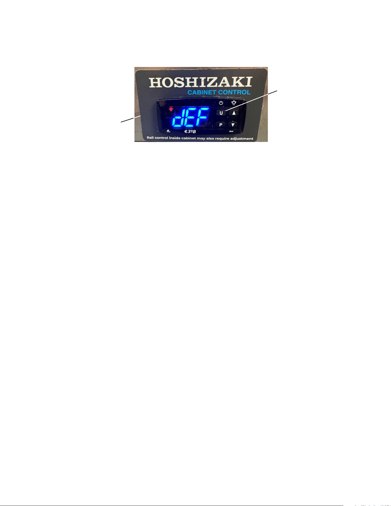
8) The cabinet control module will display "dEF" for 30 minutes at initial startup to prechill
the rail. This can be bypassed by pressing and releasing the 'U' button (standby button)
twice to turn the cabient control module off and on again. See Fig. 42.
Cabinet Control Module
U Button
Fig. 42
34
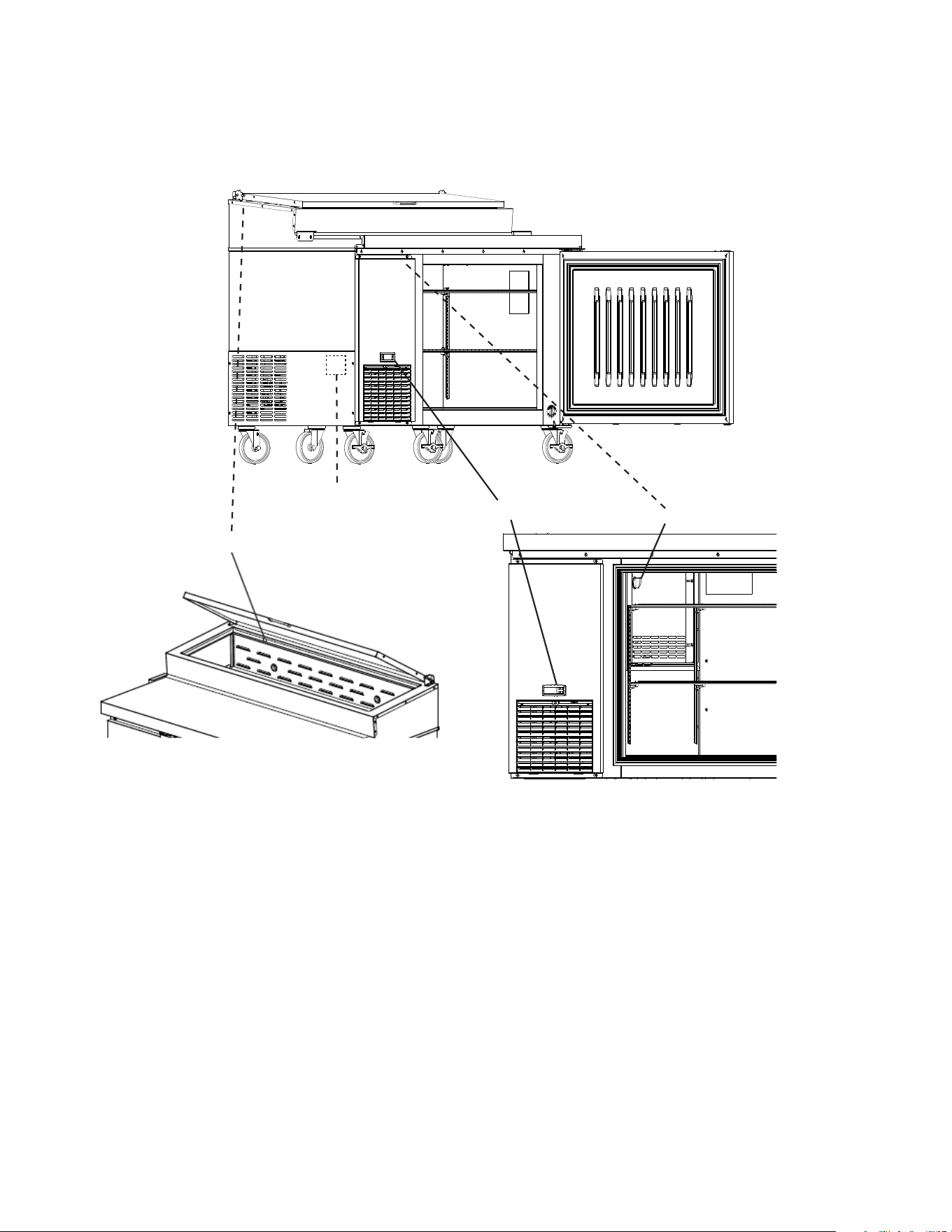
C. Controls and Adjustments
This appliance utilizes a rail control module, rail control dial, rail light sensor, and a
cabinet control module. See Fig. 43.
Fig. 43
Rail Light Sensor
Cabinet Control Module
Rail Control Dial
Rail Control Module
35
Fig. 44
a) Rail Control Dial Adjustment. To adjust day mode temperature setpoint, rotate the
control knob counterclockwise for a warmer setting and clockwise for a colder setting.
See Fig. 45. 1 is the warmest setting and 9 is the coldest setting. Note: There is a
2.25°F (1.25°C) difference between each number setting on the control knob. Night
mode is a programmed temperature offset of 8°F (4.4°C) above the day mode rail
control dial setting. NOTICE! The rail control dial controls compressor operation.
It does not control cabinet fan motor operation. For cabinet fan motor operation
control see "II.C.2. Cabinet Temperature Control."
Factory Default: 5 (27°F (-2.8°C)).
b) Rail Cover Open; Day Mode: With the rail cover open, day mode engages. The rail
light sensor communicates with the rail control module to maintain the temperature
setting of the rail control dial.
c) Rail Cover Closed; Night Mode: With the rail cover closed, night mode engages.
The rail light sensor communicates with the rail control module to maintain offset rail
temperature setting for night time storage of product in the rail area.
WARNING! To prevent night time mode from engaging during day time mode
operation, make sure the rail light sensor is clean and not obstructed.
Rail Light Sensor
Rail Control Dial
Rail Control Dial
Setpoint Position 5
Fig. 45
12 o'clock Setpoint Position
1. Rail Area Day Mode and Night Mode Temperature Control
This appliance utilizes 2 controls to control the temperature in the rail area: The rail
control dial and the rail light sensor. See Fig. 44. The rail light sensor communicates to
the rail control module whether the rail cover is open or closed. When the cover is open,
the rail is in day mode and maintains the temperature set using the rail control dial. When
the rail cover is closed, the rail is in night mode and the rail temperature is automatically
adjusted. See below for details.
36
2. Cabinet Temperature Control and Display
The cabinet temperature is controlled by the cabinet control module and cabinet fan
motor(s) in conjunction with the rail control dial, rail control module, and cabinet fan relay.
The cabinet control module energizes the cabinet fan motor(s) when needed.
Note: The cabinet control module does not energize or de-energize the compressor.
WARNING! Adjusting the cabinet temperature setpoint only affects cabinet fan
motor operation. It does not control compressor operation. The cabinet fan motor
draws its cooling air from the rail area when the rail area is calling for cooling and the
compressor is energized.
a) Cabinet Temperature Setpoint Adjustment: The cabinet temperature is displayed
on the control module. To change the cabinet temperature setpoint, press the up
arrow and release. See Fig. 46. SP1 and the cabinet setting ashes. Press the up or
down arrow button to the desired temperature setpoint. 5-sec. later, the temperature
setpoint is saved and the display returns to normal display. NOTICE! Do not adjust
the temperature setpoint more than 2°F (1°C) at a time. Allow the temperature to
stabilize for a minimum of 8 hours before making further temperature setpoint
adjustments.
Factory Default: 35°F (1.7°C)
b) Cabinet Temperature Display Scale (°F or °C):
There are 4 temperature display settings from which to choose.
The factory temperature display default is F0 for °F whole number.
For a whole number temperature display scale value, select F0 or C0.
For a temperature display scale value to one decimal point, select F1 or C1.
Display Scale Temperature Display Style
F0 - Factory Default
35°F
C0
2°C
F1
35.0°F
C1
1. 7 °C
To change the temperature display scale value, follow the steps below:
1) Press the "U" and "P" buttons together for 5 seconds. i.uP is displayed.
2) Press the "P" button. The current display setting (F0, F1, C0, or C1) and I.uP start
ashing.
3) Press the up or down button until the desired temperature display style is displayed.
37
Cabinet Control Module
Cooling
Icon Used
for Cabinet
Fan Motor
Front
Panel
Down Button
Up Button
Fig. 46
4) Press the "P" button to save the selection. I.uP is displayed. To return to normal display
mode, press and hold the "U" button for 5 sec. Display returns to normal display mode.
If no other button is pressed after pressing the "P" button, 25 sec. later, display returns
to normal display mode.
Note: If no selection is saved within 30 seconds, the display returns to normal mode
and the temperature display scale remains unchanged.
D. Cabinet Control Display Icons
Control module icons inform you of energized components and if the appliance is in
alarm. Note: Cooling icon used for cabinet fan motor operation.
Control Module Icons
Icon Meaning
U
Cooling icon used for Cabinet Fan Motor
Cabinet thermistor calling for cooling. Cabinet fan motor energized if compressor energized.
Note: Control module cooling icon used for cabinet fan motor operation.
Alarm
Appliance is in alarm. See "II.F. Alarm Safeties" for details.
Defrost
Appliance is in defrost cycle. See "II.E. Defrost" for details.
Defrost Icon
Alarm Icon

38
E. Defrost
DANGER
Risk of Fire or Explosion Flammable Refrigerant Used
• Do not use mechanical devices to defrost.
• Do not puncture refrigerant tubing. Risk of re or explosion due to puncture of
refrigerant tubing; follow handling instructions carefully.
Risque De Feu Ou D'Explosion Le Frigorigène Est Inammable
• Ne pas utiliser d'appareils mécaniques pour dégivrer le réfrigérateur.
• Ne pas perforer la tubulure contenant le frigorigène. Risque de feu ou d'explosion si la
tubulure contenant le frigorigène est perforée; suivre les instructions de manutention
avec soin.
1. Automatic Defrost
Defrost is a time/temperature initiated, temperature terminated heated defrost.
• Defrost Initiation: When the appliance is plugged in, the 6 hr. defrost timer
starts. Once the 6 hr. defrost timer terminates, the rail control module checks the
defrost thermistor for defrost initiation temperature of 41°F (5°C) or below. If the
defrost thermistor is not at or below 41°F (5°C), the rail control module continues
in the cooling mode. If defrost thermistor is at or below 41°F (5°C), defrost
initiates. Ifenergized, the compressor, rail fan motor(s), and cabinet fan motor(s)
de-energize. Defrost heater energizes, cabinet display cooling icon turns off, defrost
icon turns on, and "dEF" is displayed.
Note: To manually reset the 6-hr. defrost timer, initiate a manual defrost then
terminate using the same procedure as initiating a manual defrost.
See "II.E.2. Manual Defrost" below.
• Cabinet Display During Defrost: "dEF" is displayed. The cooling (cabinet fan
motor) icon turns off and the defrost icon turns on. The defrost icon and "dEF" are
displayed for 30 min. Note: Cabinet fan motor(s) are locked out during the 30-min.
defrost icon and "dEF" display time. The compressor and rail fan motor(s) are
controlled separately by the rail thermistor and rail control module.
• Defrost Termination: After the 5-min. minimum defrost timer terminates and the
defrost thermistor warms to 41°F (5°C), the rail control module terminates defrost
and resets the 6 hr. defrost timer. Note: Cabinet display is not affected by the rail
defrost thermistor temperature and continues to show "dEF" until the 30-min. "dEF"
display timer terminates.
• The compressor and rail fan motor(s) energize 3-min. after defrost termination
(drip time). Note that the 3 min. rail fan motor delay time is a maximum; if the
defrost thermistor cools to 36°F (2.2°C) before the 3 min. rail fan motor delay timer
terminates, the rail fan motor(s) energize.
39
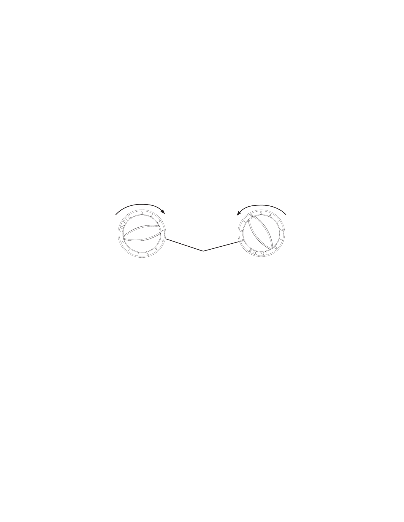
Clockwise
Counterclockwise
Control Knob
Fig. 47
• Cabinet Display After Defrost: After the 30-min. "dEF" display timer terminates, and
the cabinet thermistor is above setpoint, the cooling (cabinet fan motor) icon turns
on, the cabinet fan motor(s) energize, and the "dEF" display changes to "PdF".
"PdF" is displayed for 30 min. or until the cabinet temperature cools to 1.8°F (1°C)
above setpoint; the cabinet display then returns to cabinet temperature.
2. Manual Defrost
To manually initiate or terminate a defrost cycle: Turn the control knob clockwise to put
the control knob 9 setting in the 12 o'clock position, pause for 3 to 5 sec., then turn
the control knob counterclockwise to any position below control knob 7 setting in the
12o'clock position. Defrost initiates or terminates within 5 sec. See Fig. 47.
Note: When defrost is manually initiated it continues through the normal defrost cycle
unless manually terminated. Cabinet display is not affected by the rail control and
continues to show "dEF" until the 30-min. "dEF" display timer terminates.
To manually terminate defrost and reset the defrost timers and return the cabinet control
module back to the cabinet temperature display, unplug the appliance from the electrical
outlet, then plug it back into the electrical outlet or turn the breaker off and back on.

40
F. Cabinet Control Alarm Safeties
No alarms are available for the rail control module. The cabinet control module is the
only control with alarm capabilities. Alarm signals are designed to protect the appliance
and food product. These alarms give information or warnings in the event the appliance
is operating out of acceptable parameters. Should one of the alarms occur, follow the
instructions in the table below to address the alarm. The alarm code and alarm icon ash
with audible alarm.
Alarm Signals
Alarm Code Problem Corrective Action/Reset Details
(-)E1
Cabinet Thermistor Malfunction Alarm
Cabinet thermistor has failed.
Call a qualied service technician.
Steady tone. To silence the alarm, press and release
any button.
Appliance cycles 5 min. on, 5 min. off.
-E1 - Cabinet thermistor out of place or open.
E1 - Cabinet thermistor shorted.
Hi
High Temperature Alarm
Cabinet temperature has remained
above 57°F (13.9°C) for more than
1hour.
If obvious corrections such as closing doors/drawers
and cleaning the air lter and/or condenser do not
bring temperature back in range, call a qualied
service technician.
Steady tone. To silence the alarm, press and release
any button. The alarm icon stays on.
Automatically resets when temperature returns to
normal.
Lo
Low Temperature Alarm
Cabinet temperature has remained
below 20°F (-6.6°C) for more than
1hour.
If obvious corrections do not bring the temperature
back in range, call a qualied service technician.
Steady tone. To silence the alarm, press and release
any button. The alarm icon stays on.
Automatically resets when temperature returns to
normal.
41
G. Food Storage
WARNING
• The appliance is designed only for temporary storage of food. Employ sanitary
methods. Use for any other purposes (for example, storage of chemicals or
medical supplies such as vaccine and serum) could cause deterioration of stored
items.
• Do not block air inlets or outlets, otherwise cooling performance may be reduced.
• Do not tightly pack the cabinet. Allow some space between items to ensure good
air ow. Also allow space between items and interior surfaces.
• Do not put warm or hot foods in the cabinet. Let them cool rst, or they will raise
the cabinet temperature and could deteriorate other foods in the cabinet or
overload the appliance.
• All foods in the cabinet should be wrapped in plastic lm or stored in sealed
containers. Otherwise foods may dry up, pass their smells onto other foods, cause
frost to develop, result in poor appliance performance, or increase the likelihood
of cross-contamination. Certain dressings and food ingredients, if not stored in
sealed containers, may accelerate corrosion of the evaporator, resulting in failure.
• Do not store items near air outlets in the cabinet. Otherwise, items may freeze up
and crack or break causing a risk of injury or contamination of other food.
• The entire rail must always be covered by rail dividers and pans. Otherwise, the
appliance will not cool properly. Use only pans up to 6"(15cm) deep. Do not use
damaged rail dividers or pans.
• Ingredients must be pre-chilled to 37°F (3°C) or less before placing in rail.
• Keep the rail cover closed when not actively preparing food.
• The rail is for keeping ingredients cool while preparing food. If not actively
preparing food for a long period such as overnight, seal pans with plastic
wrap in addition to closing the rail cover. Depending on conditions, the cabinet
temperature setting may need to be adjusted to prevent items from freezing.
Alternatively, seal ingredients and store them in a refrigerator or freezer.
H. Safety Devices
1. Compressor External Protector
If combined temperature/amperage value is above the limit specied by the
compressor manufacturer, the compressor protector operates independently to turn
off the compressor. The compressor protector de-energizes the compressor until the
temperature/amperage value returns to an acceptable level.
2. Short-Cycle Protection
There is a 2-minute minimum off-time and on-time for the compressor.
Note: Time may vary with compressor overload or high-pressure switch activation.

42
I. Cooling Performance
Be sure the appliance is properly installed and located for optimum cooling performance.
If cooling performance is not at its optimum level, check the following items:
• Doors/drawers opened too often.
• Doors/drawers left open. Close.
• Cabinet too tightly packed or air inlets/outlets blocked. Allow some space between items
to ensure good air ow.
• Warm or hot foods inside. Take them out until they cool down more.
• Ambient temperature too high. Avoid installation near high heat producing equipment or
exposure to direct sunlight.
• Temperature setpoint not cold enough. Adjust to a colder setting. See "II.C. Controls and
Adjustments" for details.
• Appliance in defrost cycle. The cabinet temperature may rise temporarily during the
defrost cycle, but this will not affect the food inside.
• Pans and rail dividers not in place. The entire rail must always be covered by rail
dividers and pans (up to 6"(15cm)deep) or the appliance will not cool properly.
• Warm or hot ingredients inside rail. Only load ingredients that have been pre-chilled to
37°F (3°C) or less.
• Rail cover open when not actively preparing food. When not actively preparing food,
close the rail cover.
J. Cabinet Condensation
In the event condensation develops on the cabinet exterior, check the following items:
• Doors/drawers left open. Close.
• Ambient humidity too high. In high humidity areas it may be necessary to wipe off the
cabinet frame occasionally.
43
III. Cleaning and Maintenance Instructions
A. Cleaning
WARNING
• Unplug the appliance before cleaning to prevent electric shock by unexpected
entrance of water into the appliance or injury by moving parts. To reduce the risk
of electric shock, do not touch the plug with damp hands.
• Before cleaning the appliance, move all foods into another clean refrigerator or
freezer.
• Do not splash, pour, or spray water directly onto or into the appliance. This might
cause short circuit, electric shock, corrosion, or failure.
• Carefully follow instructions provided with cleaning and sanitizing products.
NOTICE
• To prevent damage to the plastic surfaces, do not use the following: hot water,
thinner, benzine, alcohol, petroleum, soap powder, polishing powder, alkaline
cleaner, acid, scouring pad and especially those strong cleaners for use on a
ventilating fan or a cooking range.
• To prevent corrosion and damage to stainless steel surfaces, use only products
formulated for use on stainless steel appliances. Do not use steel wool, abrasive
products, or products containing sodium hypochlorite (chlorine bleach).
• Use a clean cloth for cleaning.
1. Exterior
Wipe the exterior occasionally with a clean, soft cloth. Use a damp cloth containing
a neutral cleaner to wipe off oil or dirt buildup. Clean any rust colored spots using a
non-abrasive cleanser.
2. Cabinet Interior
Spills should be wiped up promptly to avoid unpleasant odors. The cabinet interior should
be cleaned periodically with a mild soap or detergent and warm water.
3. Door/Drawer Gaskets
Door/drawer gaskets should be cleaned regularly with mild soap and warm water to
remove dirt and grease.
4. Shelves
Remove and clean regularly.
5. Rail Light Sensor
Regularly wipe down the rail light sensor lens (located in the rail area) with mild soap and
warm water to remove dirt and grease.
44
6. Drawers
Drawers and drawer slides are removable.
• To remove a drawer: Remove all items from the drawer. Pull the drawer out to its fully
extended position. Open the safety clips (one on each side) by sliding them forward.
See Fig. 48. Lift up on the handle slightly, then pull to disengage the drawer. Be sure
to support the rear and front of the drawer while removing it. WARNING! Be sure to
close the safety clips when reinstalling the drawer.
• To remove a drawer slide (center slide containing rollers): Open the stop levers
(one on each side) by sliding them to the rear. See Fig. 49. Lift up on the drawer slide
slightly, then pull to disengage the drawer slide. WARNING! Be sure to close the stop
levers when reinstalling the drawer. Drawer slides do not require lubrication, but
drawer slides should be kept clean and free of food.
Note: Drawer slides are dishwasher safe.
Fig. 48
Safety Clips
Safety Clip
Closed
Fig. 49
Safety Clip
Open
Stop Lever
Drawer Slide
7. Cutting Board
Remove and clean the cutting board as often as necessary to maintain a clean, sanitary
work surface. Also clean the space underneath the cutting board as often as necessary
to maintain a clean, sanitary surface. After cleaning, slide the cutting board back under
the cutting board brackets. WARNING! Make sure the cutting board brackets and
cutting board are secure. Otherwise, the cutting board could come off and cause
injury.
8. Pans
Wash pans as often as necessary to maintain clean, sanitary conditions.
9. Rail, Rail Dividers, and Rail Cover
Spills and splashes should be wiped up promptly to avoid unpleasant odors. Wipe the
rail area, rail dividers, and rail cover occasionally with a clean, damp sponge or cloth
containing a neutral cleaner. Clean any rust colored spots using a non-abrasive cleanser.
Do not pour or spray water into the rail area.
WARNING!
• Support the rail cover when cleaning. Otherwise, the rail cover could close
suddenly and cause injury.
• Metal edges can cause cuts. Use care and wear protective gloves when cleaning.
Stop Lever
Closed
Stop Lever
Open
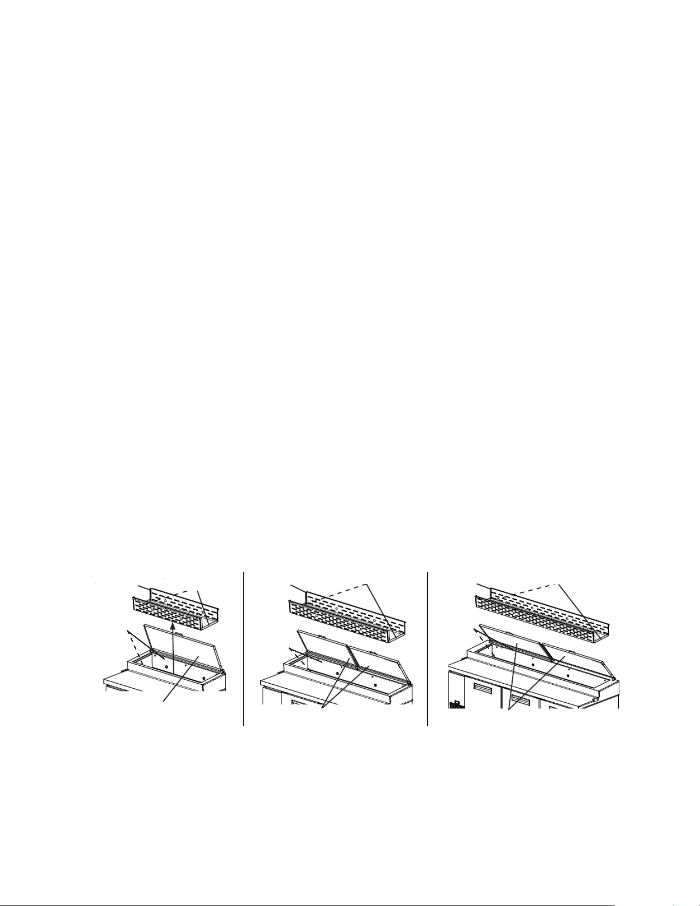
45
PR46B(-DX)
PR60B(-DX) and PR67B(-DX) PR93B(-DX)
Fig. 50
10. Rail Air Duct
1) Move all foods into another clean refrigerator or freezer.
2) Unplug the appliance. WARNING! To reduce the risk of electric shock, do not touch
the plug with damp hands.
3) Remove the pans and rail dividers from the rail. WARNING!Support the rail cover
when cleaning. Otherwise, the rail cover could close suddenly and cause injury.
4) Air Duct Panel and Rail Area Cleaning: WARNING!Metal edges can cause cuts.
Use care and wear personal protective equipment (gloves and goggles) when
cleaning.
a) Daily: Remove the pans and rail dividers. Wipe the air duct panel and rail area with a
mild soap or detergent and warm water. After cleaning, wipe the air duct panel
with water.
b) Weekly: Follow the steps below to remove and clean the air duct panel and rail area.
(1) Remove the thumbscrews and front and back mounting screws, then remove the air
duct. See Fig. 50.
(2) Wipe the air duct panel (top and bottom), rail area (sides and top), and surrounding
mounting area with mild soap or detergent and warm water. Clean any rust colored
spots using a non-abrasive cleanser. After cleaning, wipe the air duct panel with
water.
(3) Replace and secure the air duct panel in its correct position. Be sure the
thumbscrews and mounting screws are installed and tightened. NOTICE!Air duct
panels must be replaced in the proper location and orientation. See Fig. 49.
Otherwise, cooling performance will be reduced.
5) Place the rail dividers and pans (up to 6"(15cm)deep) into their correct positions.
Leave the pans empty until the appliance cools down.
6) Close the rail cover. Plug the appliance into the electrical outlet.
Rail Covers
Rail Covers
Rail Cover
Air Duct
Air Duct Air Duct
Thumbscrews
Thumbscrews Thumbscrews
7) Allow the appliance to cool down prior to loading it with food products. The entire rail
must be covered by rail dividers and pans and the rail cover must be closed.
Otherwise, the appliance will not cool properly. Leave the pans empty until the
appliance cools down.
Mounting
Screws
Mounting
Screws
Mounting
Screws
46
B. Maintenance
The appliance must be maintained in accordance with the instruction manual. Consult
with your local Hoshizaki Certied Service Representative about maintenance service.
Failure to maintain the appliance in accordance with this manual may adversely affect
safety, performance, component life, and warranty coverage.
WARNING
• Unplug the appliance before performing maintenance to prevent electric shock or
injury by moving parts. To reduce the risk of electric shock, do not touch the plug
with damp hands.
• Before performing maintenance, move all foods into another clean refrigerator or
freezer.
1. Air Filter
Remove the louver screw and check the air lter at least twice a month. When clogged,
remove the air lter. Use warm water and a neutral cleaner to wash the lter. Replace the
air lter in its correct position.
2. Condenser
Check the condenser once a year and use a brush or vacuum cleaner to clean the
condenser as required. More frequent cleaning may be required depending on conditions.
3. Condensate Drain Hose
Clean the condensate drain as often as necessary to maintain proper ow. Follow the
steps below.
1) Unplug the appliance from the electrical outlet. WARNING! To reduce the risk of
electric shock, do not touch the plug with damp hands.
2) Remove the left side panel.
3) Remove the condensate drain hose.
4) Clean the condensate drain hose.
5) Replace the condensate hose in its correct position.
6) Replace the left side panel in is correct position.
7) Plug the appliance back into the electrical outlet.
4. Power Supply Connection
If the plug or power cord is damaged, contact your local Hoshizaki service representative
or local Hoshizaki distributor immediately and ask for repairs.
All other maintenance or service on the appliance should be performed in accordance
with the Hoshizaki Service Manual by a qualied service technician.
47
IV. Preparing the Appliance for Periods of Non-Use
When shutting down the appliance for more than one week, follow the instructions below.
WARNING
When preparing the appliance for long storage, prevent the doors/drawers from
closing to reduce the risk of children getting trapped.
NOTICE
When preparing the appliance for long storage, clean the appliance. See
"III.A. Cleaning" for details.
1) Before shutting down the appliance, move all foods into another clean refrigerator or
freezer.
2) Unplug the appliance. WARNING! To reduce the risk of electric shock, do not touch
the plug with damp hands.
48
V. Disposal
DANGER
Risk of Fire or Explosion Flammable Refrigerant Used
• Follow handling instructions carefully in compliance with U.S. government
regulations.
• Do not puncture refrigerant tubing. Risk of re or explosion due to puncture of
refrigerant tubing; follow handling instructions carefully.
• Dispose of properly in accordance with federal or local regulations.
Risque De Feu Ou D'Explosion Le Frigorigène Est Inammable
• Suivre attentivement les instructions de manipulation conformément à la
réglementation gouvernementale.
• Ne pas perforer la tubulure contenant le frigorigène. Risque de feu ou d'explosion
si la tubulure contenant le frigorigène est perforée; suivre les instructions de
manutention avec soin.
• Éliminer conformément aux règlements fédéraux ou locaux.
WARNING
When preparing the appliance for disposal, remove the doors/drawers to reduce the
risk of children getting trapped. Leave the shelves in place so that children may not
easily climb inside.
The appliance contains refrigerant and must be disposed of in accordance with
applicable national, state, and local codes and regulations. Refrigerant must be
recovered by properly certied service personnel.

49
618 Hwy. 74 South, Peachtree City, GA 30269 USA (P) 770.487.2331 (F) 770.487.3360 hoshizakiamerica.com 1A8069-010