Operator’s Manual
Cream whipper
model CW 5 Plus - 37b
Translation of the original instructions

Section 1 : Introduction
OPERATOR’S MANUAL
OPERATOR’S MANUAL
2
INTRODUCTION

Section 1 : Introduction
OPERATOR’S MANUAL
3
INTRODUCTION
This manual is divided into the following six sections:
INTRODUCTION
OPERATION
MAINTENANCE
TROUBLESHOOTING
PARTS
UTILIZATION
A Parts of the Machine 5
B Specifications 5
C Machine’s operation:
Setting dispensing time 6
IMPORTANT RULES 7
D Rinsing Phase and Washing procedure: 8
E Disassembling Primary Parts: 9 - 10
F Disassembling Secondary Parts: 10 - 11
G Cleaning and Sanitizing Disassembled Parts: 11
H Cleaning Machine: 12
L Assembling Secondary Parts of the Machine: 12 - 13
M Assembling Primary Parts of the Machine: 14 - 15
N Sanitizing: 16 - 17
P Replacing the gaskets 18
Q General alarm indications displayed on the control panel
Causes and solutions 20
R Troubleshooting – flowchart 21
S Replacement Parts: 26
Section 1 : Introduction
OPERATOR’S MANUAL
OPERATOR’S MANUAL
4
INTRODUCTION
1
2
4
6
5
7
9
10
11
13
17
18
12
19
8
15
16
14
3
20
Section 1 : Introduction
OPERATOR’S MANUAL
5
INTRODUCTION
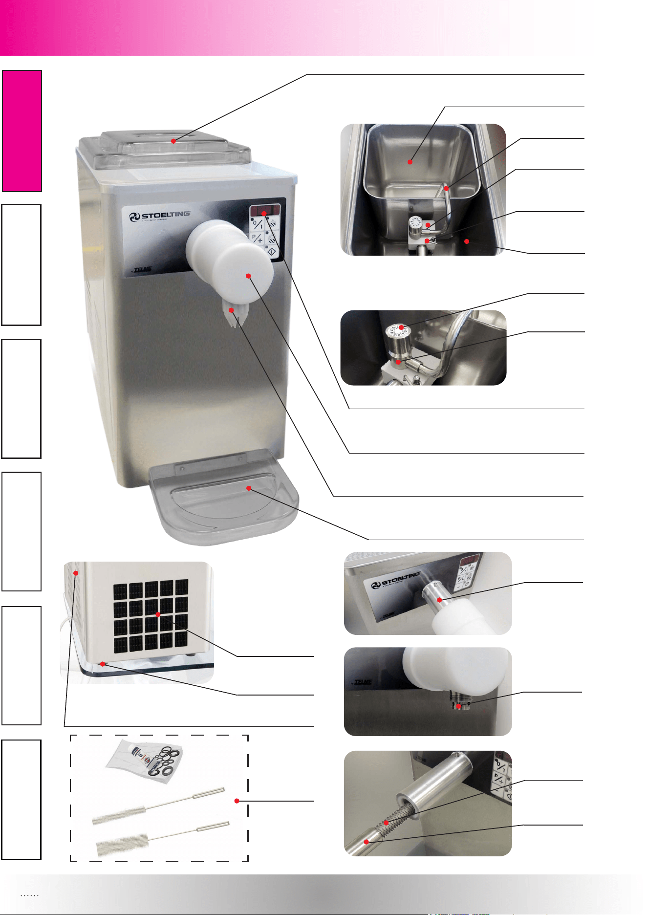
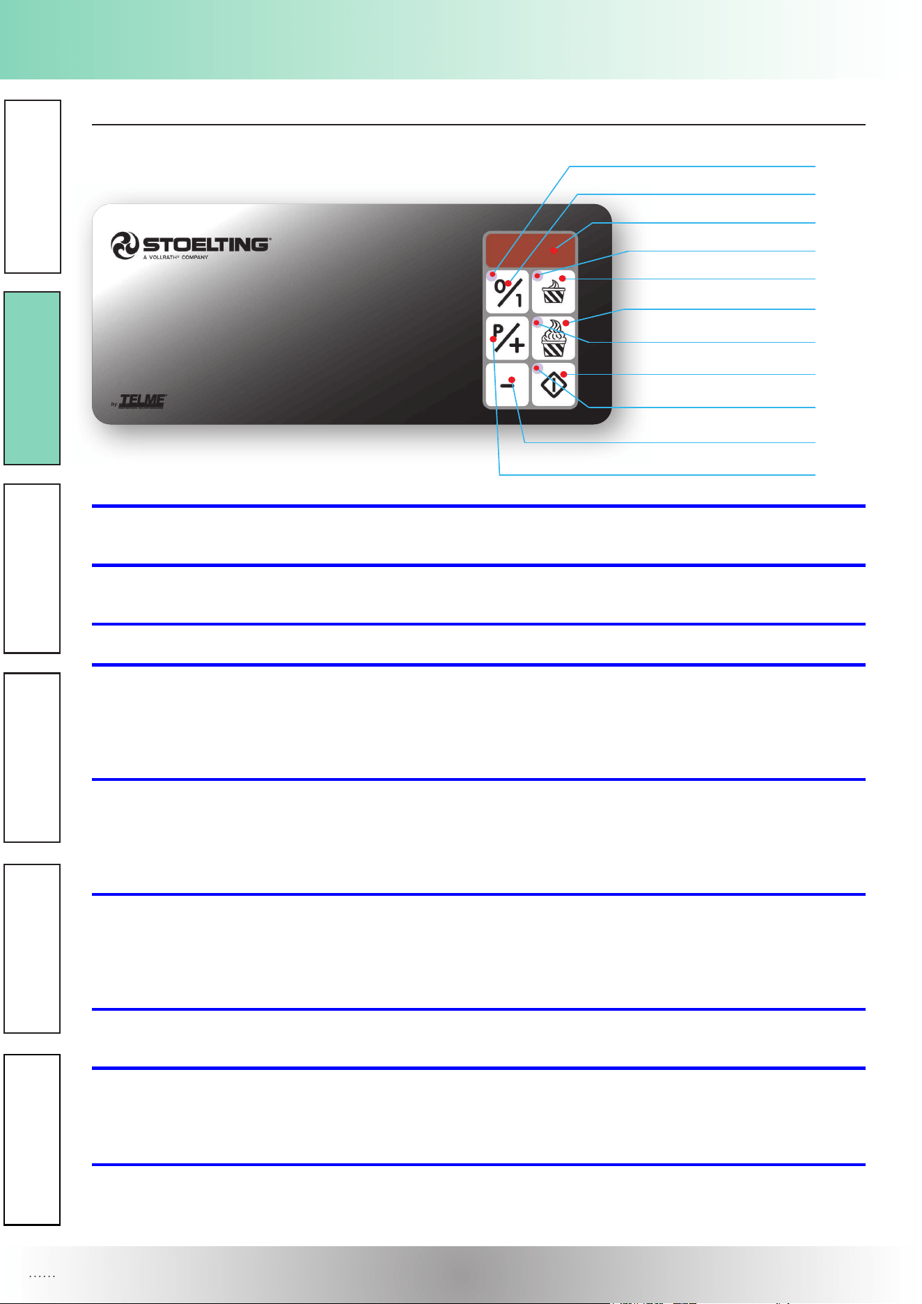
1. Lid
2. Cream Container
3. Cream aspiration tube
4. Pump
5. Fixing rod
6. Refrigeration tank
7. Air Regulator Knob (for Adjustment)
8. Air regulator
9. Control panel
10. Faucet
11. Nozzle
12. Drip tray
13. Outlet tube
14. Cream dispenser
15. Labyrinth
16. Labyrinth-tube
17. Condenser outlet
18. Support feet
19. Outer panels
20. Spare Parts Kit and Brushes
B Specications
Model CW 5 PLUS - 37b
Net weight lbs / kg 77 / 35
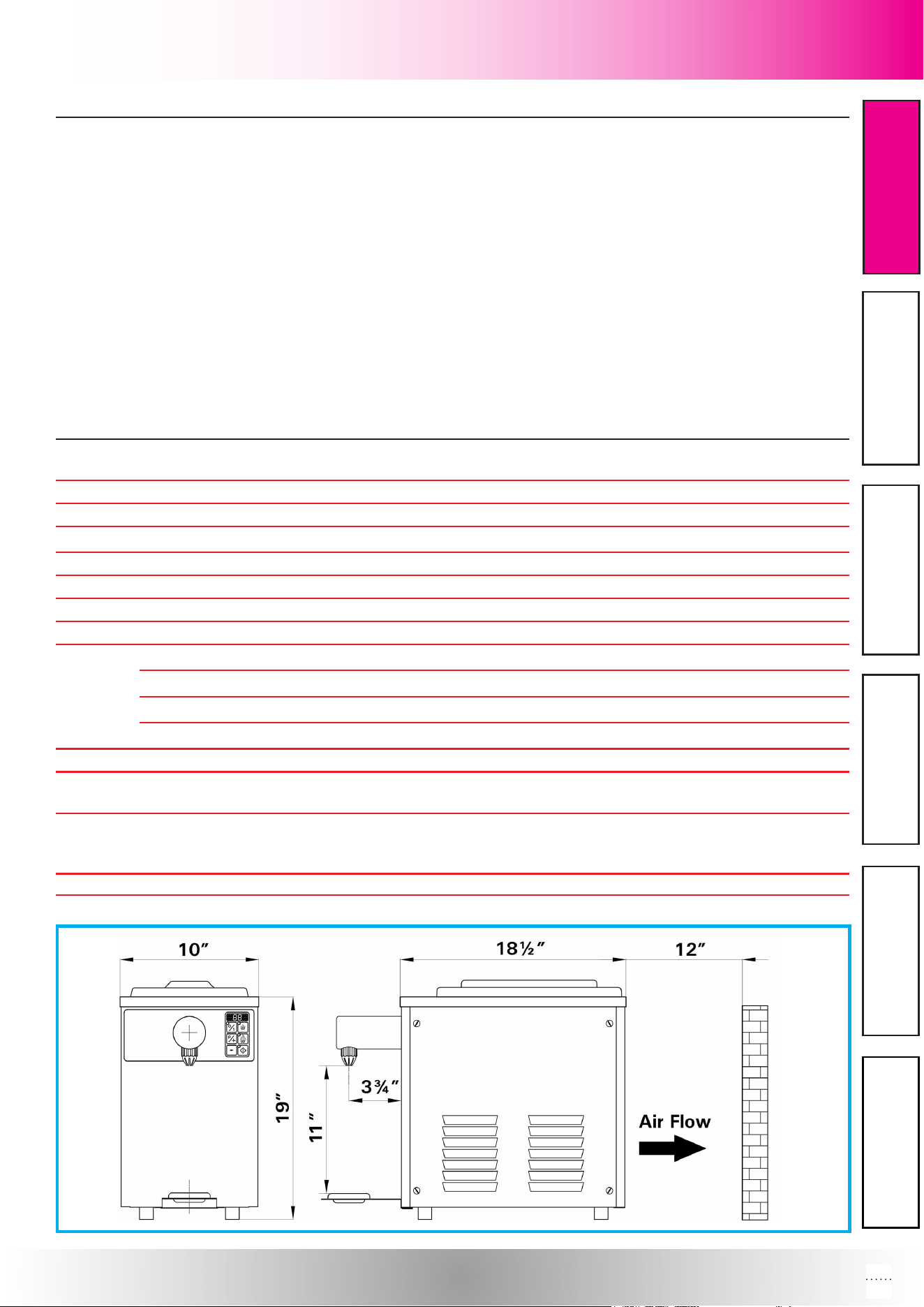
Dimensions width / height / depth 10” (25cm) / 19” (49cm) / 18 ½” (47cm)
Hopper Volume (max) gal / L 1,32 / 5
Max. ambient temperature °F / °C 95 / +35
Compressor Number / Btu/hr 1 / 290
Coolant gas (type) R134a
air version (quantity) g / oz 160 / 5,64
AIR version: (coolant gas pressure) bar 9,8 ÷ 10,3
"CONDENSATION" (coolant gas temperature) °C / °F +42 ÷ +45 / 107,6 ÷ 113
AIR version: (coolant gas pressure) bar 0,2 ÷ 0,1
“EVAPORATION” (coolant gas temperature) °C / °F -22 ÷ -25 / -7,6 ÷ -13
Drive motor Number / hp 1 / 0,57
Rated power kW 0,6
Rated current A 11
Power supply
Voltage (Volts) 115
Frequency (Hz) 60
Phases (PH) 1
Plumbing Fittings -
A Parts of the Machine
Section 2 : Utilization
OPERATOR’S MANUAL
6
UTILIZATION
C Machine’s operation:
1a
1
2
3a
3
4
4a
6
7
1. ON/OFF button For switching the machine on and o. Press to pre-
pare the machine to operate and subsequently the tank temperature is displayed on the digital display (2).
1a. Power LED Light indicates that the machine is powered up.
When lit the LED indicates that the machine is supplied with electricity.
2. Digital display Displays the functions and data set.
3.
“P1 Dispensing” button Time dispensing button. The factory set value is
7 corresponding to about 1 oz. By pushing the button “7”, after P1 parameter, it is possible to set a value
between 1 and 90 for the automatic dispensing of the whipped cream. The setting of value 1 corresponds to
a 0,5 sec. dispensing, up to a maximum value of 90, which corresponds to a 45 sec. dispensing. When the
button is active, its signal led (3a) is on.
4. “P2 Dispensing” button Time dispensing button. The factory set value is
21 corresponding to about 3 oz. By pushing the button “7”, after P2 parameter, it is possible to set a value
between 1 and 90 for the automatic dispensing of the whipped cream. The setting of value 1 corresponds to
a 0,5 sec. dispensing, up to a maximum value of 90, which corresponds to a 45 sec. dispensing. When the
button is active, its signal led (4a) is on.
5.
“P3 Dispensing” button Button for the dispensing of the whipped cream:
- Manual, if the “PU” parameter has been set in “P3” programming. The dispensing will go on until the
“P3 Dispensing” button is released.
- Continuous, if the “CO” parameter has been set in “P3” programming. The dispensing will go on up to
the following pressing of the “P3 Dispensing” button. When the button is active, its signal led (5a) is on.
6.
“ Adjustment - Button” This button is active only during the programming
functions, its pushing allows the decrease of the selected value.
7. “Programming/Adjustment +” Button Dual function button:
a) the adjustment parameters (P1, P2, P3) as well as the corresponding set values are viewed in
sequence on the digital display by pressing the button for some seconds;
b) in the programming function the set value can be increased by pressing the button.
5
5a
Section 2 : Utilization
OPERATOR’S MANUAL
7
UTILIZATION
Setting dispensing time
DURING ITS FACTORY INSPECTION, THE MACHINE HAS BEEN PROGRAMMED WITH OPTI-
MAL VALUES FOR THE OPERATION.
IF PARAMETER VALUES DO NEED TO BE ALTERED, MAKE ANY NECESSARY MACHINE PRO-
GRAMMING CHANGES BEFORE STARTING PRODUCTION.
Keep the PROGRAMMING/ADJUSTMENT + (7) button pressed for a few seconds to access the program-
ming functions and change the type of dispensing.
The operation set at the factory proceeds as follows:
Code Function
Having pressed the PROGRAMMING/ADJUSTMENT + button (7), the P1 code ashes on
the digital display. Some seconds later, a numerical value indicating the dispensing time set
appears automatically on the digital display. Press adjustment buttons (6) and (7) to increa-
se or reduce the dispensing time value. The time can be adjusted within a range of 1 to 90.
The setting of value 1 corresponds to a 0,5 sec. dispensing, up to a maximum value of 90,
which corresponds to a 45 sec. dispensing. The factory set value is 7 = about 1 oz.
Having pressed the PROGRAMMING/ADJUSTMENT + button (7), the P2 code ashes on
the digital display. Some seconds later, a numerical value indicating the dispensing time set
appears automatically on the digital display. Press adjustment buttons (6) and (7) to increa-
se or reduce the dispensing time value. The time can be adjusted within a range of 1 to 90.
The setting of value 1 corresponds to a 0,5 sec. dispensing, up to a maximum value of 90,
which corresponds to a 45 sec. dispensing. The factory set value is 21= about 3 oz.
P1
P2
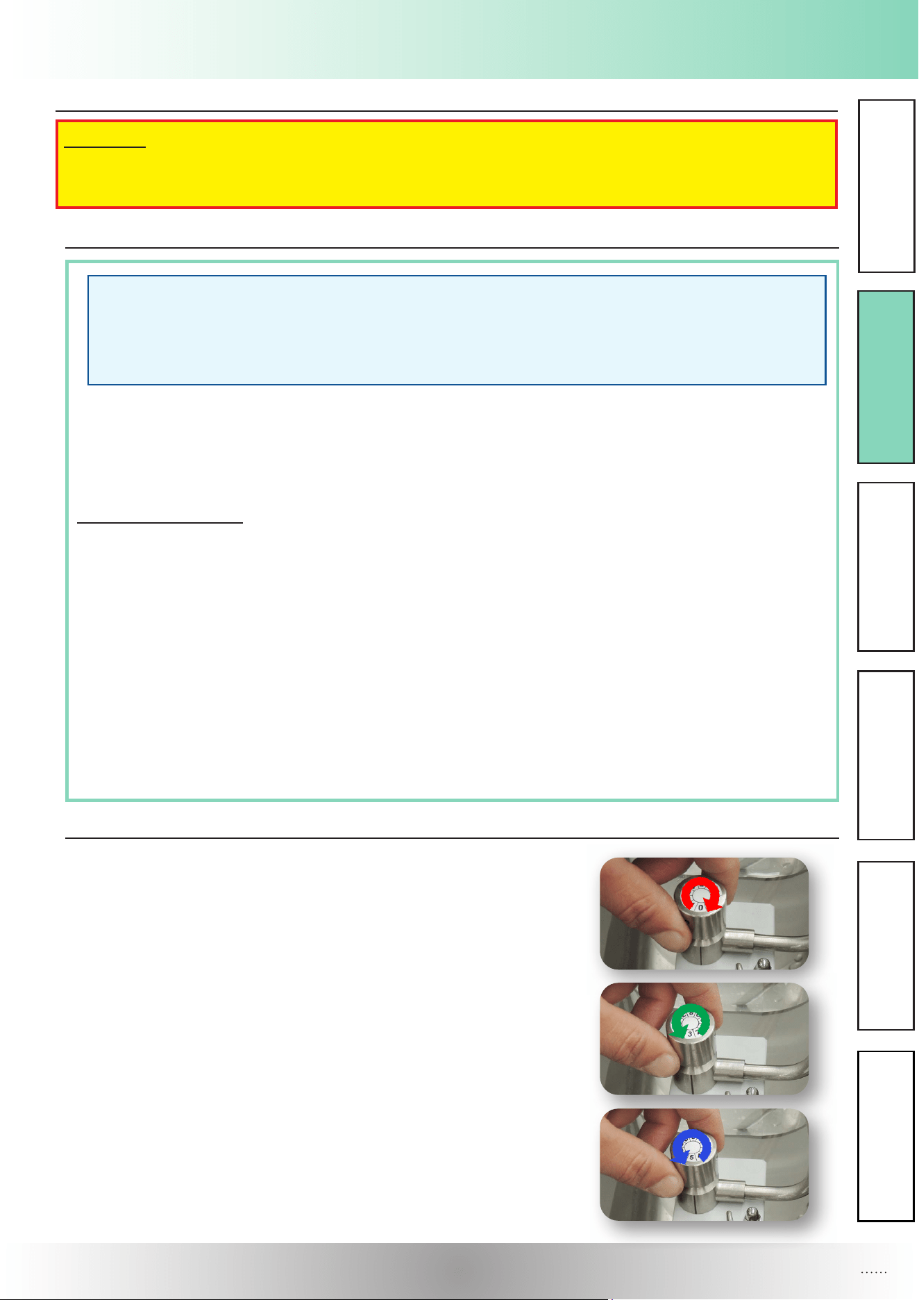
Setting Air Regulator
- Rotate knob clockwise until the air regulator is closed (position 0).
- Rotate knob counterclockwise to necessary value. Standard po-
sition is between 2 - 3.
- For normal use do not rotate the knob exceeding position 5.
IMPORTANT RULES
NEVER:
! ADD SUGAR IN CRISTALS, ONLY LIQUID SUGAR.
! DISASSEMBLE THE PUMP FOR CLEANING.
Section 3: Operation
OPERATOR’S MANUAL
8
OPERATION
Having pressed the PROGRAMMING / ADJUSTMENT + button , the P3 code ashes on the digital
display.
Setting the continuous dispensing (Co). Maintain the dispensing active until the washing solution
mix contained in the cream container is used up.
DO NOT RUN THE PUMP WITHOUT SOLUTION IN ORDER TO AVOID DAMAGING IT
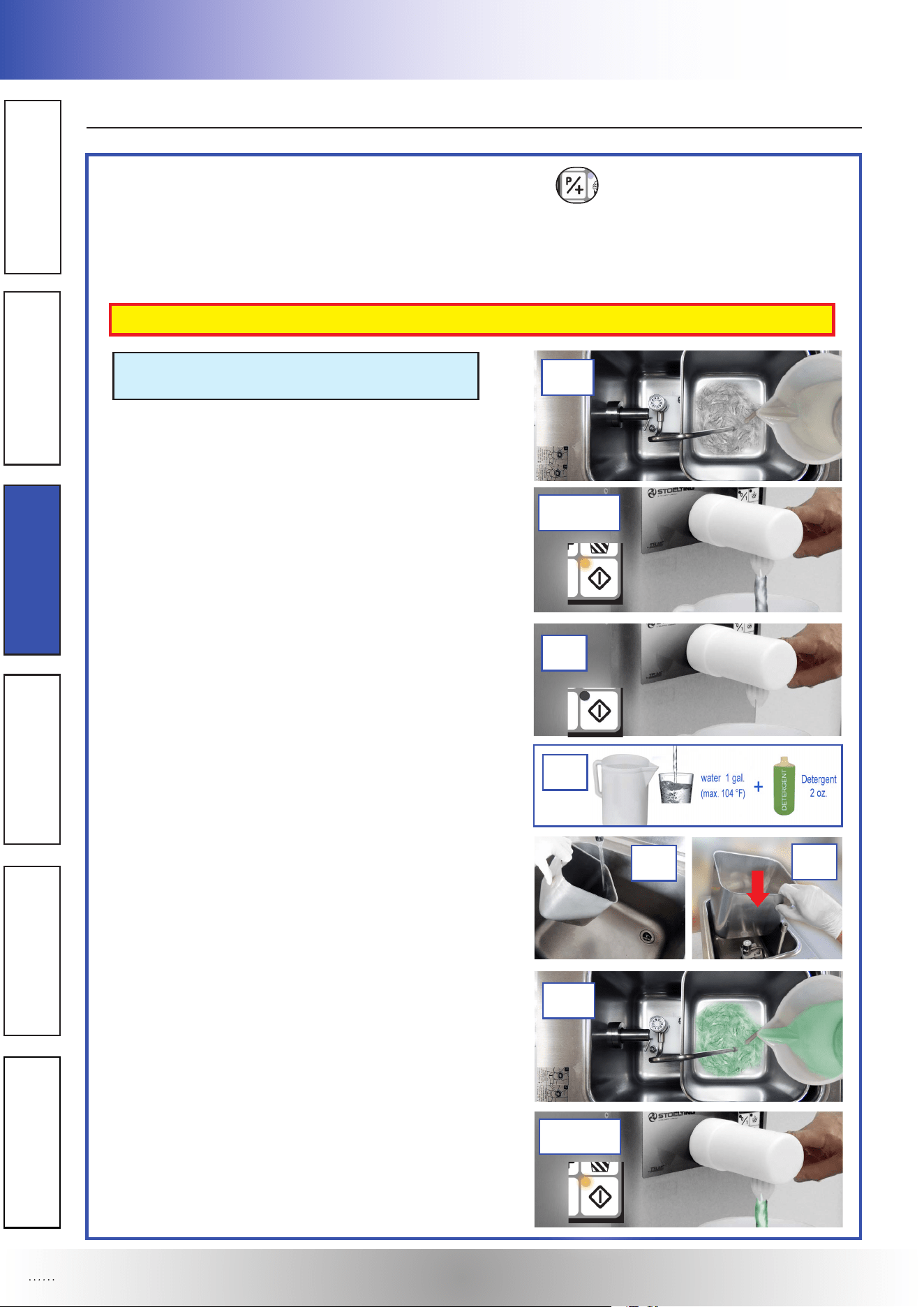
NOTE: ROTATE THE AIR REGULATOR KNOB
TO POSITION BETWEEN 1 - 2
- (D1) Pour drinking water at room temperature into the
cream container up to half of its capacity, to wash all
residues of cream.
- (D2) Place a suitable container under the dispensing
faucet.
- (D3) Press the “DISPENSING” button to drain the
rinsing water in the cream container into the appro-
priate container placed under the dispensing faucet .
- (D4) Press the “DISPENSING” button again to stop
the continuous functioning when the cream container
is empty.
- (D5) Remove the cream container and wash it in
a solution of 1 gallon of water at 104 °F and 2 oz
of detergent (according to detergent instructions).
Rinse the cream container with room temperature
water until it’s clean of detergent and place it in the
refrigeration tank.
- (D6) Pour inside the cream container a solution com-
posed of 2 quarts of warm water at 104 °F and 1 oz
of detergent (according to detergent instructions).
- (D7) Place a suitable container under the dispensing
faucet .
- (D8) Press the “DISPENSING” button to drain the
water and detergent in the cream container into the
appropriate container placed under the dispensing
faucet .
D Rinsing Phase and Washing procedure:
D2-D3D2-D3
D4D4
D1D1
D7-D8D7-D8
D6D6
D5D5
D5D5
D5D5
Section 3 : Operation
OPERATOR’S MANUAL
OPERATOR’S MANUAL
9
OPERATION
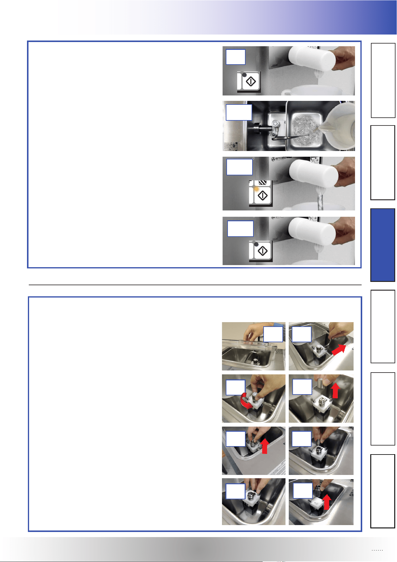
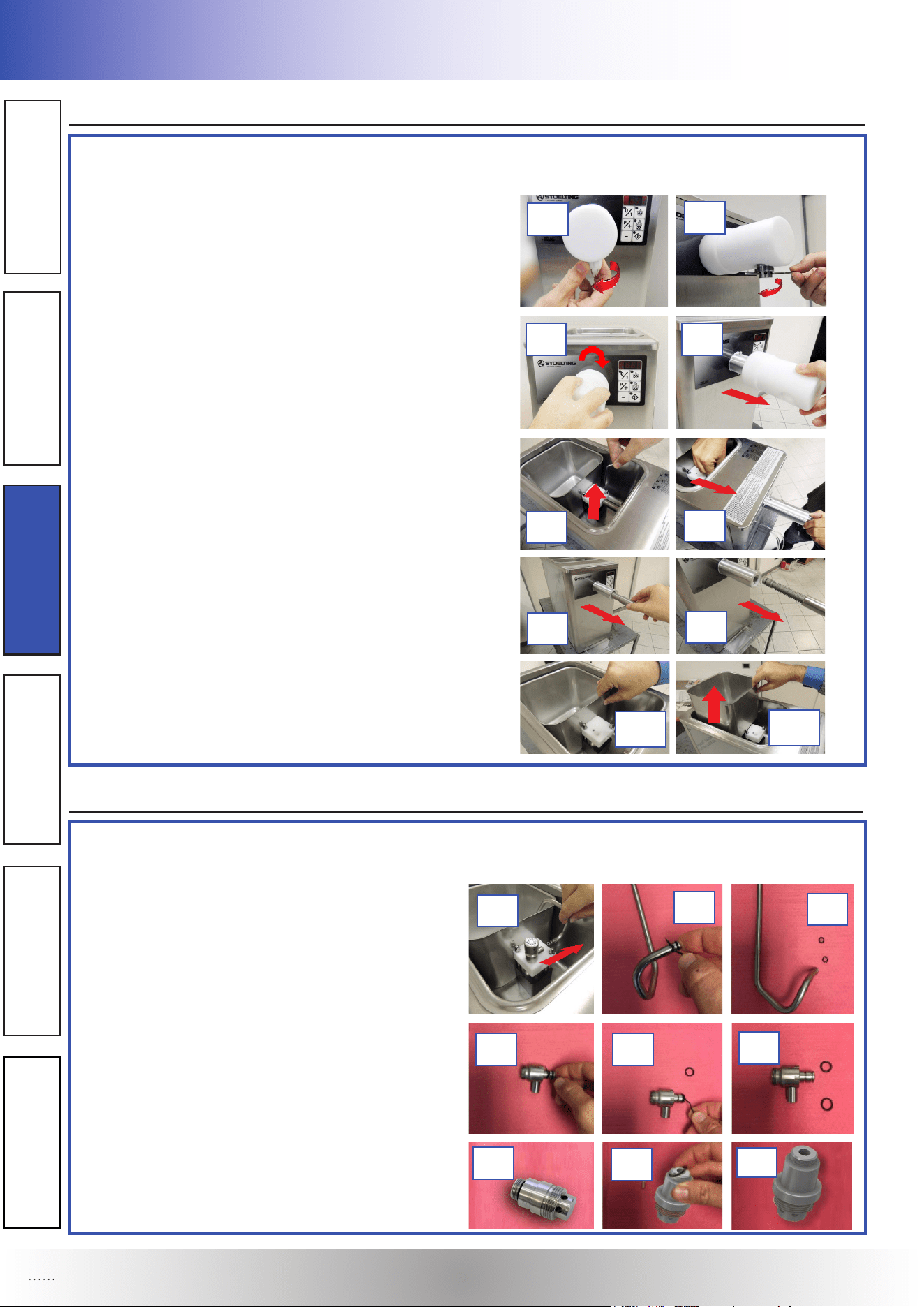
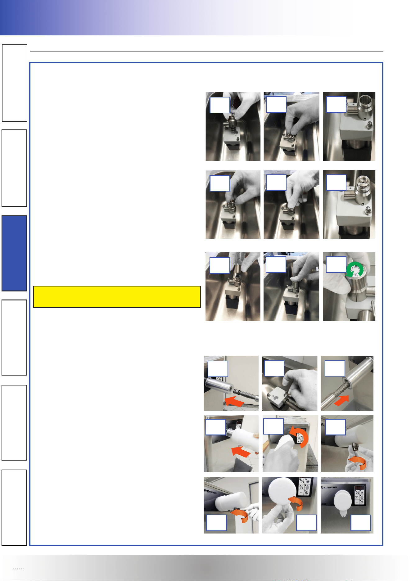
Disassembling of the cream aspiration tube and of the air regulator of the pressurization pump.
- (E1) Remove the lid on the refrigeration tank.
- (E2) Remove the cream aspiration tube.
- (E3) Turn the air regulator knob counterclockwise and
remove it vertically.
- (E4) Pull the valve assembly out vertically.
- (E5) Pull the air regulator body out vertically from the
pump cover.
E1E1 E2E2
E3E3
E3E3
E4E4 E4E4
E5E5
E5E5
E Disassembling Primary Parts:
- (D9) Press the “DISPENSING” button again to stop
the continuous functioning when the cream container
is empty.
- (D10) Repeat operations (D6-D7-D8-D9) with 2 quar-
ts of room temperature water to wash all residues of
detergent from the machine.
D9D9
D10D10
D10D10
D10D10
Section 3: Operation
OPERATOR’S MANUAL
10
OPERATION
Removing of the O-Rings gaskets of the cream aspiration tube, of the air regulator and of the cream dispenser.
- (F1) Remove the cream aspiration tube from the
air regulator.
- (F2) Remove the gaskets on the cream aspiration
tube using a non-metallic pointy tool, taking care of
not damaging the gaskets’ seatings.
- (F3) Remove the gaskets on the air regulator body,
using a non-metallic pointy tool, taking care of not
damaging the gaskets’ seats.
- (F4) Remove the gasket from the cream dispenser,
using a non-metallic pointy tool, taking care of not
damaging the gasket seat.
E6E6
E6E6
E7E7 E7E7
E8E8
F Disassembling Secondary Parts:
F1F1
F2F2
F2F2
F3F3 F3F3
F3F3
E Disassembling Primary Parts:
Disassembling of the faucet, of the labyrinth and of the cream container.
- (E6) Turn the nozzle clockwise and turn the cream di-
spenser clockwise using the xing rod included in the
spare parts kit.
- (E7) Turn faucet 45° to the right and remove it.
- (E8) Remove xing rod.
- (E9) Remove labyrinth tube and labyrinth.
- (E10) Remove the cream container vertically.
E10E10
E9E9
E9E9
E9E9
E10E10
E10E10
F4F4
F4F4
F4F4
Section 3 : Operation
OPERATOR’S MANUAL
OPERATOR’S MANUAL
11
OPERATION
- (G1) Place all parts in 90° to 110°F (32°C to 43°C) solu-
tion composed by 2 gallons of warm water and 2 oz of
detergent (according to detergent instructions). Use the
brushes that shipped with the machine to clean all holes
of the the removed parts (air-valve, labyrinth, labyrinth-tu-
be, air regulator body, valve socket, etc.).
- (G2) Rinse all parts with clean water at 90° to 110°F
(32°C to 43°C) .
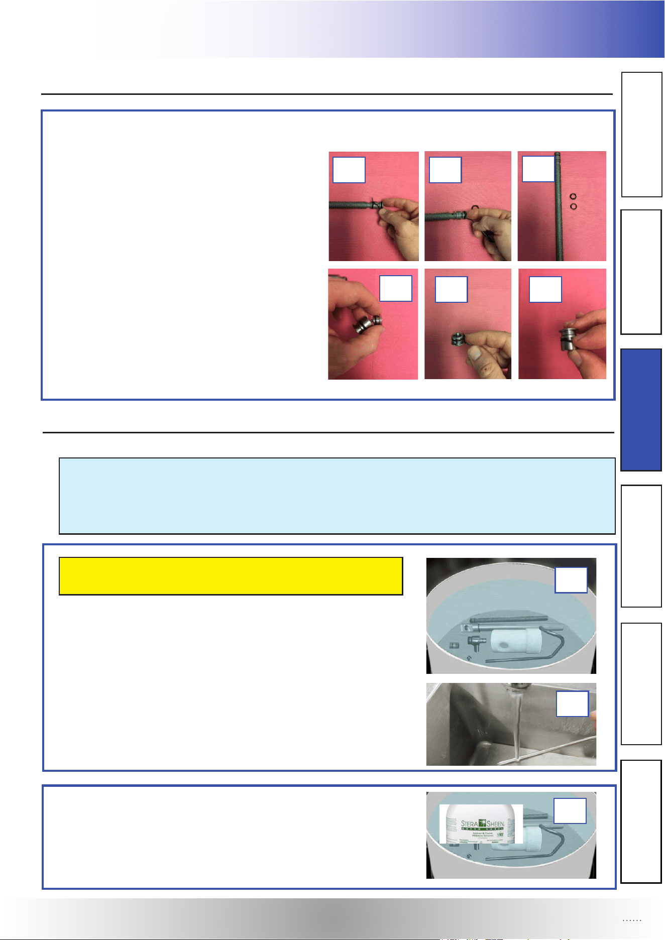
Disassembling valve assembly, removing of the O-Ring gaskets of the labyrinth and of the valve assembly.
- (F5) Remove the gaskets on the labyrinth, using a
non-metallic pointy tool, taking care of not damaging
the gaskets’ seatings.
- (F6) Take out the regulating valve from the valve
socket.
- (F7) Remove the gasket from the valve, using a
non-metallic pointy tool, taking care of not damaging
the gasket seating.
- (F8) Remove the gasket from the valve socket,
using a non-metallic pointy tool, taking care of not
damaging the gasket seating.
F Disassembling Secondary Parts:
F5F5 F5F5
F5F5
F7F7 F8F8
G Cleaning and Sanitizing Disassembled Parts:
Disassembled parts require complete cleaning, sanitizing and air drying before assembling. Local
and state health codes will dictate the procedure required. Some state health codes require a four
sink process (pre-wash, wash, rinse, sanitize, air dry), while others require a three sink process (wi-
thout the pre wash step). The following procedures are a general guideline only. Consult your local
and state health codes for the procedures required in your location.
Be sure to use the brushes that shipped with the machine
to properly clean the parts.
- (G3) Place all parts in the sanitizing solution (composed
by 2 gallons of warm water and 2 oz of Stera Sheen sa-
nitizer, according to STERA-SHEEN instructions) for at
least 5 minutes, then remove and let air dry completely
before assembling in the machine with sanitized gloves.
G1G1
G2G2
G3G3
F6F6
Section 3: Operation
OPERATOR’S MANUAL
12
OPERATION
Note: When dismantling parts for washing, regularly check that gaskets are intact and replace them
if damaged or dilated. Use only genuine gaskets, made of food-compatible rubber. Lubricate new
gaskets with food compatible grease and fit them on.
When nished with the washing, all machine components need to be reassembled as follows:
- (L1) Place the gasket on the cream dispenser.
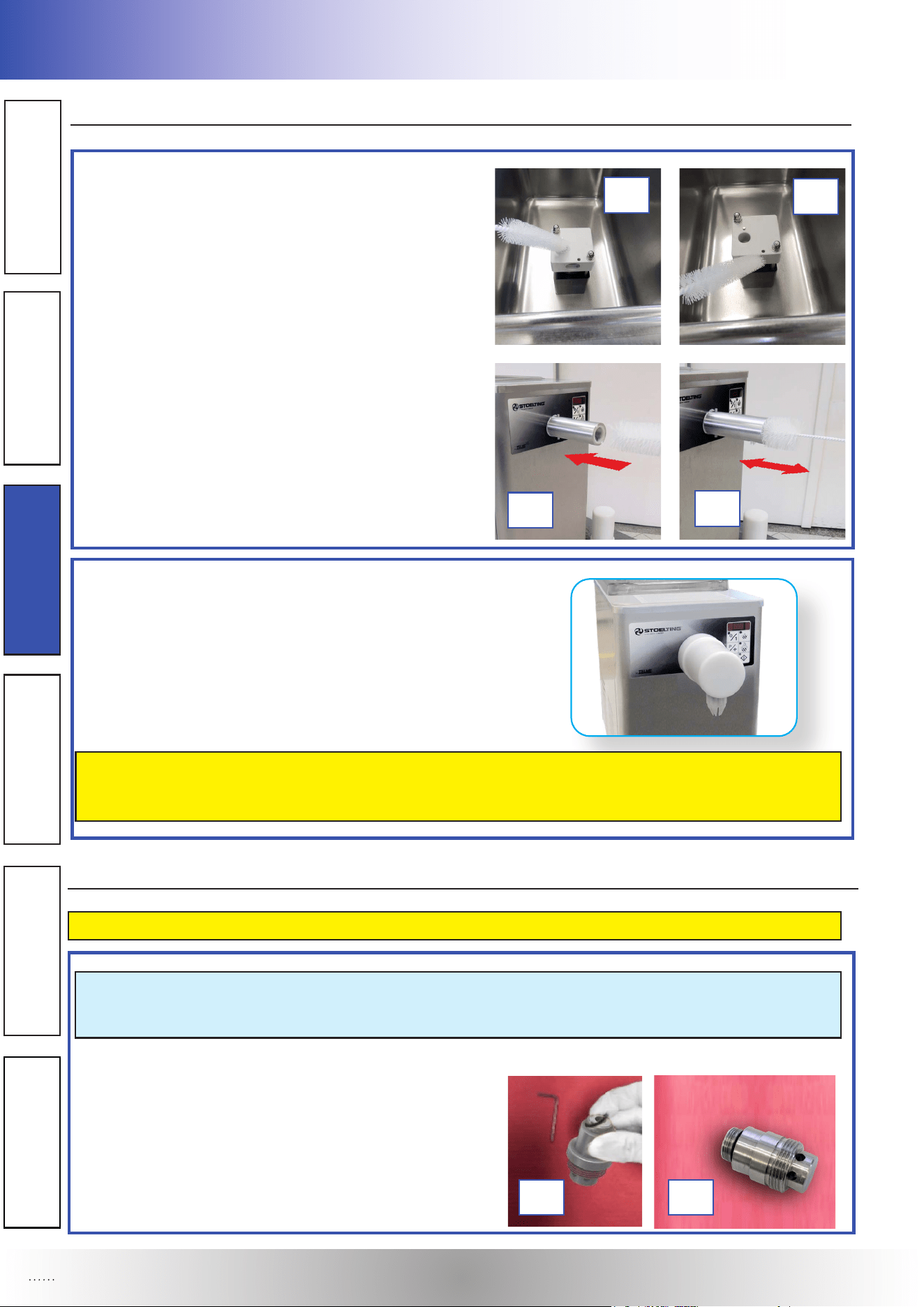
- (H1) Using a detergent solution and the small barrel
brush provided, clean the holes of the body pump by
dipping the brush in the solution and brushing the in-
side of the holes.
- (H2) Using a detergent solution and the big barrel
brush provided, clean the hole of the outlet tube by
dipping the brush in the solution and brushing the
inside of the hole.
H Cleaning Machine:
- The exterior of the machine should be kept clean at
all times to preserve the luster of the stainless steel.
A high grade of stainless steel has been used on the
machine to ease cleanup. To remove spilled or dried
mix, wash the exterior with 90° to 110°F (32°C to 43°C)
mild detergent water and wipe dry.
Do not use highly abrasive materials, as they will mar the nish. A mild alkaline cleaner is recom-
mended. Use a soft cloth or sponge to apply the cleaner. For best results, wipe with the grain of
the steel.
L Assembling Secondary Parts of the Machine:
L1L1 L1L1
H1H1
H1H1
H2H2
H2H2
FOR ALL PROCEDURES OF ASSEMBLING USE APPROPRIATE GLOVES.
Section 3 : Operation
OPERATOR’S MANUAL
OPERATOR’S MANUAL
13
OPERATION
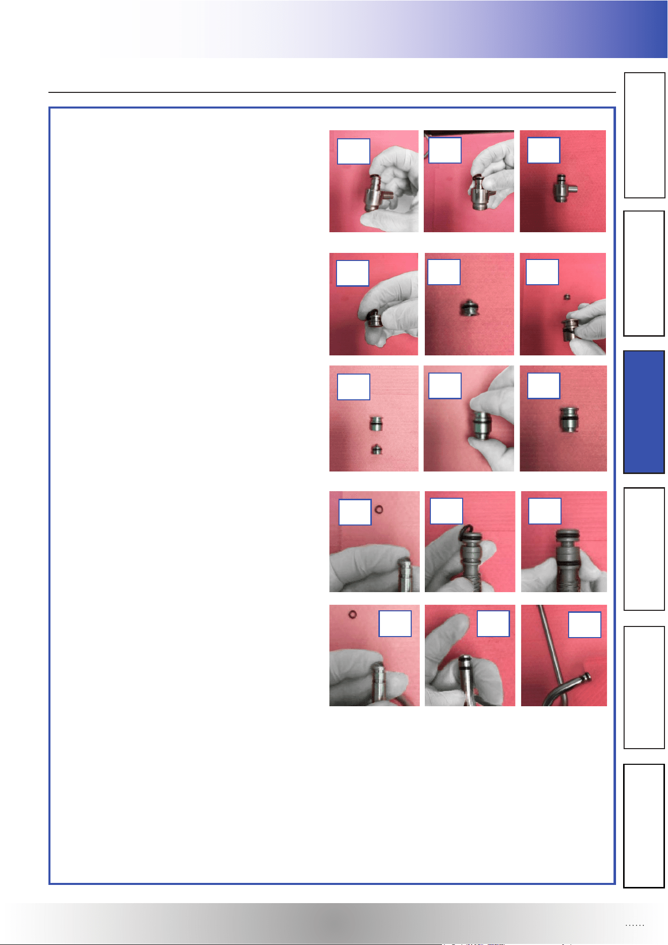
Reassembling of the air regulator body.
- (L2) Insert the 2 O-Ring gaskets on the air regu-
lator body.
• Reassembling of the valve assembly.
- (L2) Insert the O-Ring gasket on the valve.
- (L3) Insert the O-Ring gaske on the valve socket.
- (L4) Assemble the air valve with the valve socket.
• Reassembling of the labyrinth.
- (L5) Insert the 2 O-Ring gaskets on the labyrinth.
• Reassembling of the cream aspiration tube.
- (L6) Insert the 2 O-Ring gaskets on the cream
aspiration tube.
L Assembling Secondary Parts of the Machine:
L2L2 L2L2
L2L2
L2L2 L3L3
L2L2
L4L4 L4L4
L4L4
L5L5 L5L5
L5L5
L6L6
L6L6
L6L6
Section 3: Operation
OPERATOR’S MANUAL
14
OPERATION
M Assembling Primary Parts of the Machine:
M5M5 M6M6
M4M4
M7M7
M8M8M7M7
Reassembling of the air regulator onto the pump cover.
- (M1) Insert the air regulator body on the pump cover.
- (M2) Insert the valve assembly in the air regulator
body.
- (M3) Screw clockwise the air-regulation knob on
the air regulator body.
Note: SEE SETTING AIR REGULATOR ON
PAGE 7.
Reassembling of the labyrinth, labyrinth tube and faucet.
- (M4) Insert the labyrinth into the hole on the outlet
tube. Insert the xing end of the labyrinth in the
pump cover.
- (M5) Insert the xing rod in the hole of the pump
cover.
- (M6) Insert the labyrinth tube into the hole on the
outlet tube.
- (M7) Insert the faucet on the outlet tube, rotate it
counterclockwise to block it on the front panel.
- (M8) Turn counterclockwise the cream dispenser
onto the labyrinth tube (if necessary use the xing
rod included in the spare parts kit).
- (M9) Turn counterclockwise the nozzle onto the
cream dispenser.
M1M1 M1M1
M1M1
M2M2 M2M2
M2M2
M3M3
M3M3
M8M8 M9M9 M9M9
M3M3
Section 3 : Operation
OPERATOR’S MANUAL
OPERATOR’S MANUAL
15
OPERATION
M Assembling Primary Parts of the Machine:
M10M10
M10M10
M10M10
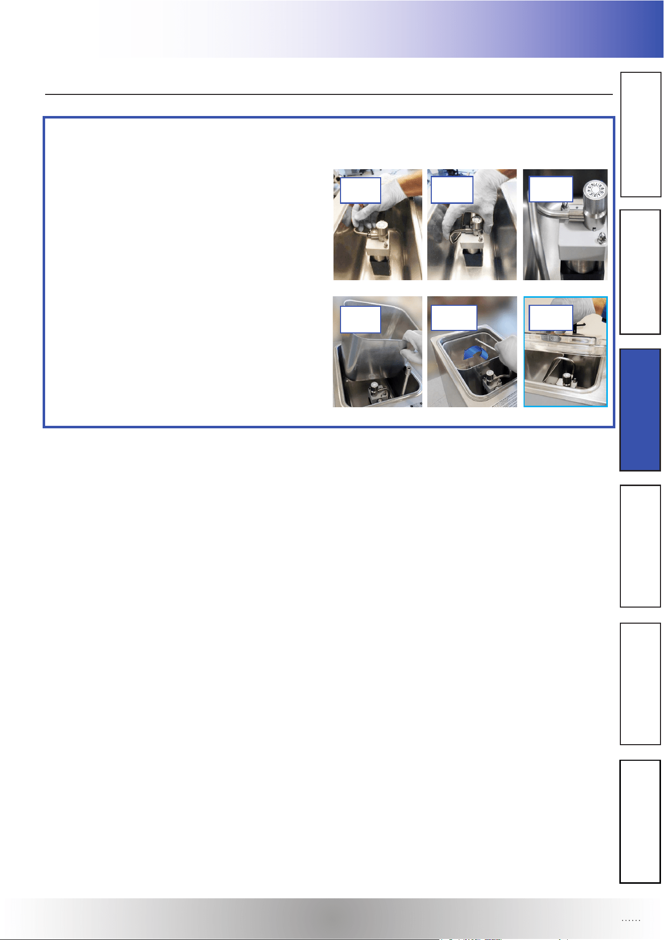
Reassembling of the cream aspiration tube, positioning of the cream container and lid.
- (M10) Insert the cream aspiration tube in the hole
of the air-regulator.
- (M10) Push the tube to x it properly in the air-re-
gulator.
- (M11) Place the cream container in the refrigera-
tion tank.
- (M11) Rotate the cream aspiration tube into the
cream container.
- (M11) Put the lid on the refrigeration tank.
M11M11 M11M11
M11M11

Section 3: Operation
OPERATOR’S MANUAL
16
OPERATION
FOR ALL PROCEDURES USE SANITIZED GLOVES.
SANITIZING MUST BE DONE AFTER THE MACHINE IS CLEAN AND JUST BEFORE THE
MACHINE IS FILLED WITH CREAM. SANITIZING THE NIGHT BEFORE DOES NOT ENSURE
SANITIZATION THE NEXT DAY. HOWEVER, YOU SHOULD ALWAYS CLEAN THE MACHINE
AND PARTS AFTER USING IT.
DO NOT RUN THE PUMP WITHOUT SOLUTION IN ORDER TO AVOID DAMAGING IT.
NOTE: THE UNITED STATES DEPARTMENT OF AGRICULTURE AND THE FOOD AND DRUG
ADMINISTRATION REQUIRE THAT ALL CLEANING AND SANITIZING SOLUTIONS USED WITH
FOOD PROCESSING EQUIPMENT BE CERTIFIED FOR THIS USE.
WHEN SANITIZING THE MACHINE, REFER TO LOCAL SANITARY REGULATIONS FOR APPLI-
CABLE CODES AND RECOMMENDED SANITIZING PRODUCTS AND PROCEDURES. THE FRE-
QUENCY OF SANITIZING MUST COMPLY WITH LOCAL HEALTH REGULATIONS. MIX SANITIZER
IN QUANTITIES OF NO LESS THAN 1 GALLON OF 90°F TO 110°F (32°C TO 43°C) WATER. ALLOW
SANITIZER TO CONTACT THE SURFACES TO BE SANITIZED FOR 5 MINUTES. ANY SANITIZER
MUST BE USED ONLY IN ACCORDANCE WITH THE MANUFACTURER’S INSTRUCTIONS AND
TO PROVIDE A 100 PARTS PER MILLION STRENGTH SOLUTION.
N Sanitizing:
Section 3 : Operation
OPERATOR’S MANUAL
OPERATOR’S MANUAL
17
OPERATION
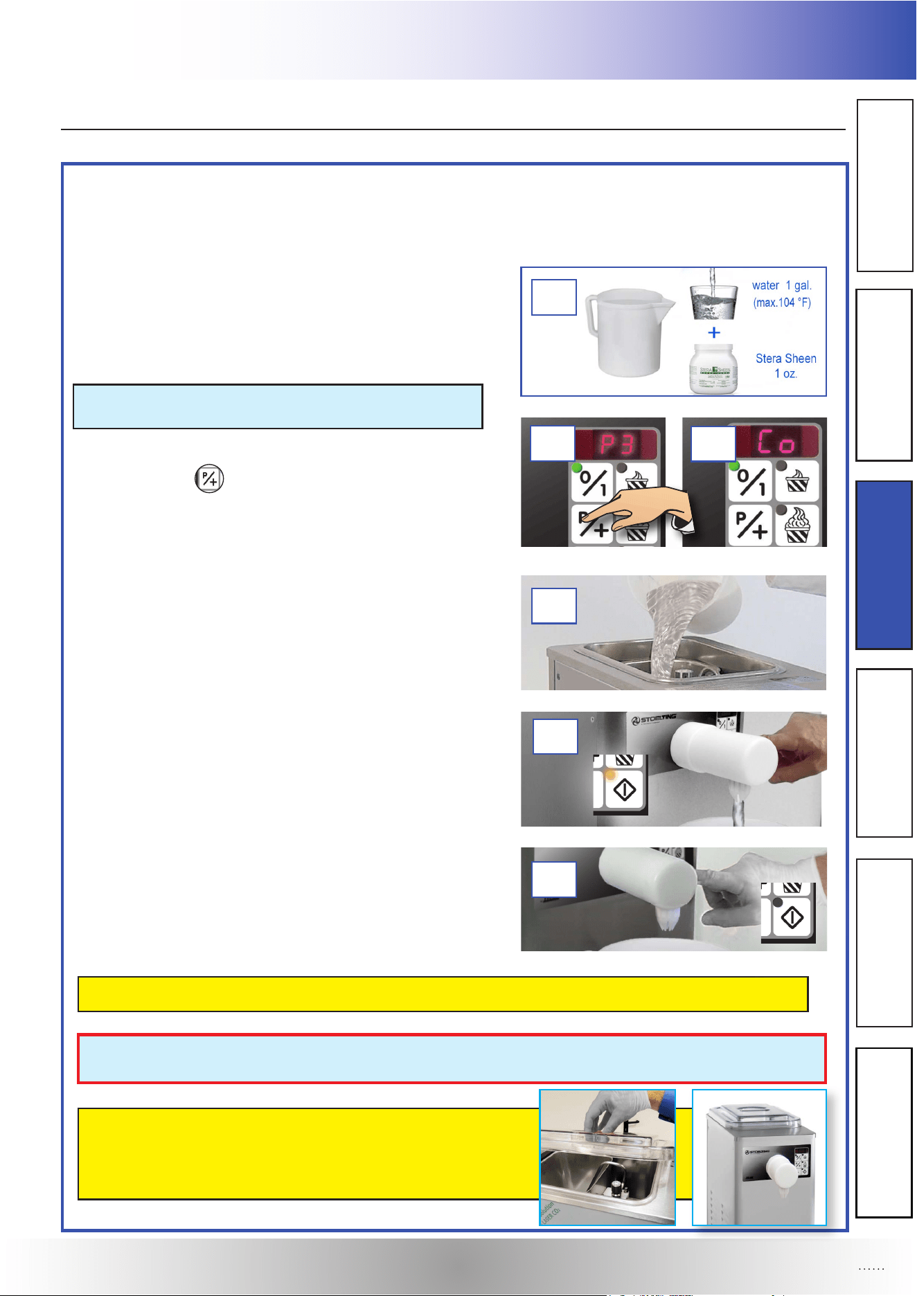
After reinstalling all the machine’s components (as previously described), carry out a sanitization with water
solution and disinfecting STERA-SHEEN manufactured by PURDY PRODUCTS. Follow accurately the next
steps:
- (N1) Prepare a pail with a solution composed by 1 gal. of
water (max 104 °F) and 1 oz. of disinfecting STE-
RA-SHEEN (according to STERA-SHEEN instructions).
NOTE: ROTATE THE AIR REGULATOR KNOB
TO POSITION BETWEEN 1 - 2
- (N2) Having pressed the PROGRAMMING / ADJUST-
MENT + button
, the P3 code ashes on the digital
display.
- (N3) Setting the continuous dispensing (Co). Maintain
the dispensing active until the washing solution contai-
ned in the cream container is used up.
- (N4) Pour solution into the cream container.
- (N5) Place a suitable container under the dispensing
faucet.
- (N5) Press the “DISPENSING” button to drain the solu-
tion in the cream container into the appropriate container
placed under the dispensing faucet.
- (N6) Press the “DISPENSING” button again to stop
the continuous functioning when the cream container
is empty.
DO NOT RUN THE PUMP WITHOUT SOLUTION IN ORDER TO AVOID DAMAGING IT.
A POTABLE WATER RINSE IS NOT NECESSARY UNLESS SO SPECIFIED BY STATE OR
LOCAL ORDINANCE.
AFTER THE SANITIZATION, CLOSE THE LID AND DO
NOT TOUCH WITH THE HANDS ANYMORE, NOT DRY
WITH CLOTHES OR PAPER ALL PARTS IN DIRECT
CONTACT WITH FOOD.
N Sanitizing:
N1N1
N2N2
N3N3
N4N4
N5N5
N6N6
Section 4 : Maintenance
OPERATOR’S MANUAL
18
MAINTENANCE
P Replacing the gaskets
CHECKING INTERVAL: 500 hours or quarterly
AUTHORISED OPERATOR: 1 Operator
TIME NEEDED: 5 minutes
TOOL: Non-metallic pointy tool
- Regularly check the integrity of the gaskets and substitute them if they are broken, worn or swollen.
- Only use original gaskets, made of food-safe rubber.
- The machine is supplied with a full set of spare gaskets and food grease tube.
DO NOT PUT GASKETS IN THE INDUSTRIAL DISHWASHER, AS THE HIGH TEMPERATURES
COULD DEFORM THEM, MAKING THEM UNUSABLE.
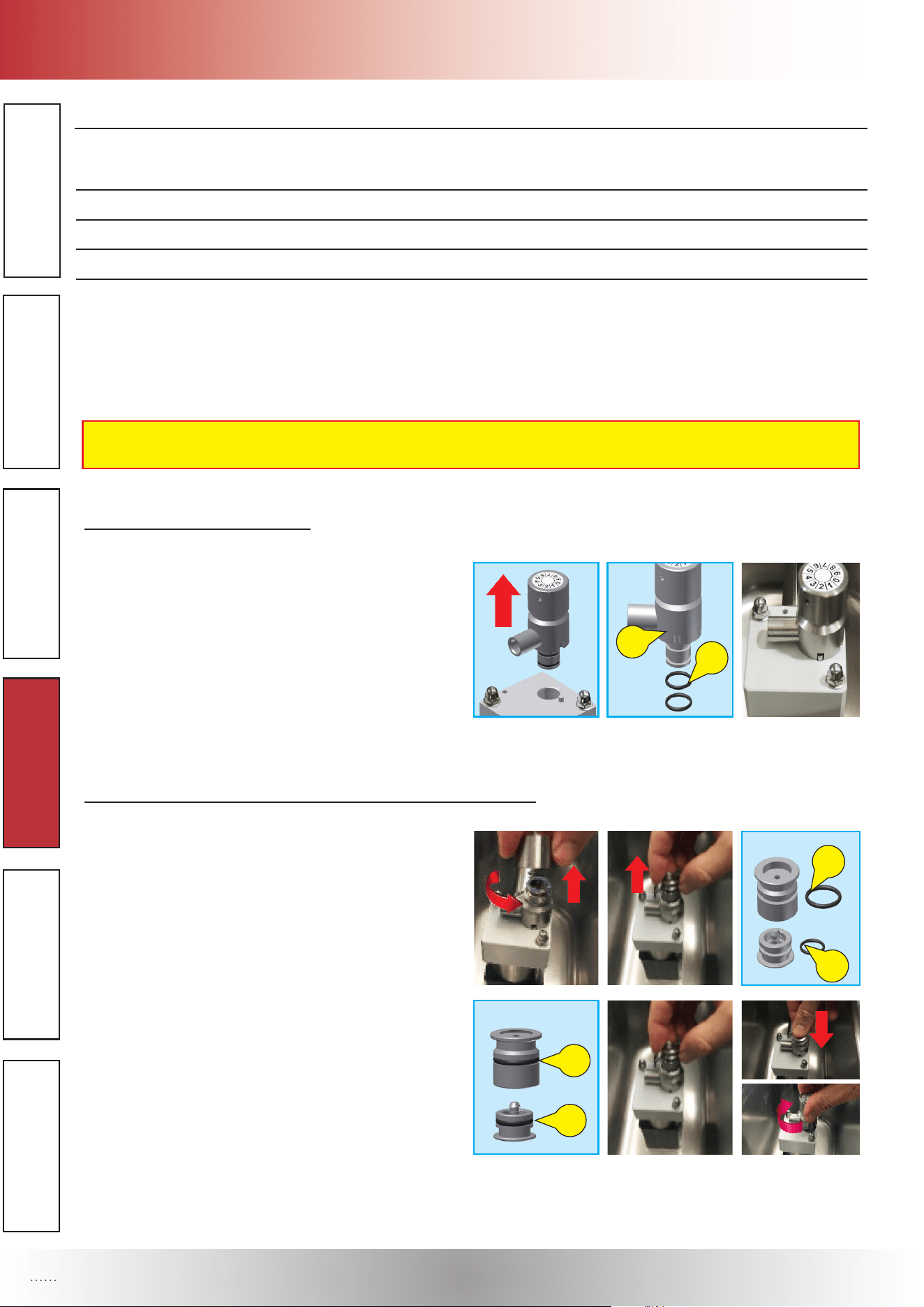
a) Gaskets of the air-regulator:
• Remove the air-regulator from the pump cover. Re-
move the worn gaskets OR (1) from the air-regulator
(2), using a non-metallic pointy tool, taking care not
to scratch the gaskets’ seats.
• Remove all product residues from the seats and t
the new gaskets lubricating it with the food grease
supplied.
• Reassemble the air-regulator on the pump cover.
b) Gaskets of the valve socket and of the air regulating valve:
• Screw the air-regulator knob counterclockwise and
remove the valve socket vertically and air valve from
the air regulator body.
• Remove the worn gaskets OR (3) from valve socket
and air valve (4) using a non-metallic pointy tool, tak-
ing care not to scratch the gaskets’ seats.
• Remove all product residues from the seat and t
the new gaskets (5-6), lubricating them with the food
grease supplied. Place the valve socket and reas-
semble air valve inside the air regulator body, turn
clockwise the air regulator knob on air regulator body.
1
2
3
4
5
6
Section 4 : Maintenance
OPERATOR’S MANUAL
19
MAINTENANCE
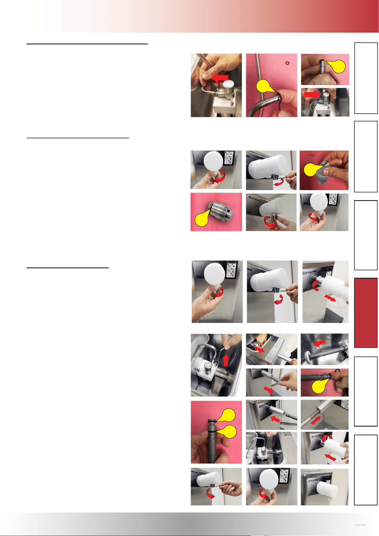
c) Gaskets of the cream aspiration tube:
• Remove the cream aspiration tube from the air-regula-
tor. Remove the worn gaskets OR (7) from the cream
aspiration tube, using a non-metallic pointy tool, taking
care not to scratch the gaskets’ seats.
• Remove all product residues from the seat and t the
new gaskets (8), lubricating them with the food grease
supplied. Reassemble the cream aspiration tube inside
the hole of the air-regulator.
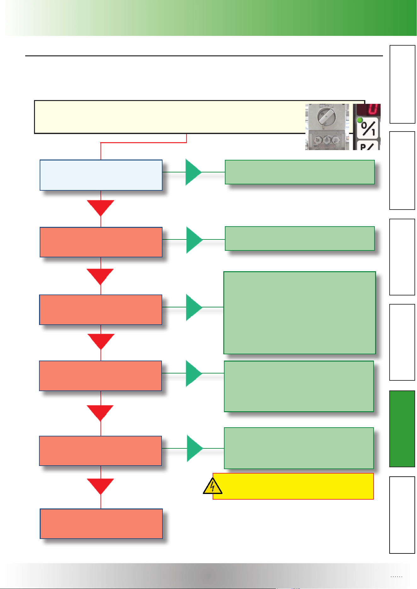
d) Gasket of the cream dispenser:
• Unscrew the nozzle counterclockwise and remove the
cream dispenser, using, if necessary, the xing rod (in-
cluded in the spare parts kit), from the dispenser faucet.
• Remove the worn gasket OR (9) from the cream dis-
penser, using a non-metallic pointy tool, taking care
not to scratch the gasket seat.
• Remove all product residues from the seat and t the
new gasket (10), lubricating them with the food grease
supplied. Screw clockwise the cream dispenser onto
the labyrinth tube inside the hole of the dispenser
faucet. Following screw clockwise the nozzle on the
cream dispenser.
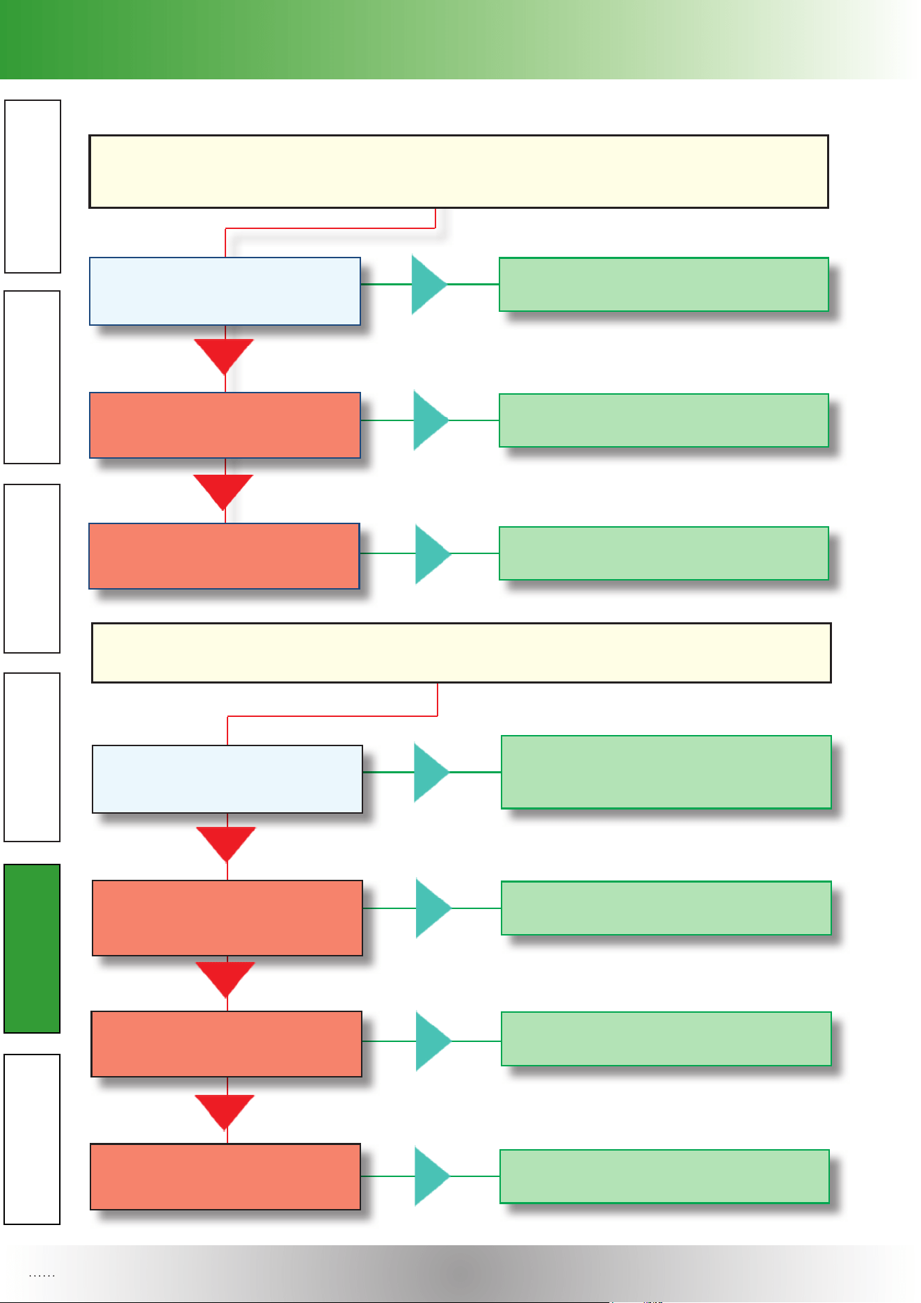
e) Gaskets of the labyrinth:
• Turn the nozzle clockwise and remove the cream
dispenser using the xing rod included in the spare
parts kit.
• Turn faucet 45° to the right and remove it.
• Remove the lid, the xing rod from the pump cover
and then extract the labyrinth tube and the labyrinth
from the machine.
• Remove the worn gaskets (11) from the labyrinth using
a non-metallic pointy tool, taking care not to scratch the
gaskets’ seats. Eliminate all product residues from the
gaskets’ seats and t the new gaskets (12), lubricating
them with the food grease supplied.
• Place the labyrinth in the pump cover and block it with
the xing rod (note: insert the xing end of the labyrinth
in the pump cover).
• Insert the labyrinth tube into the hole on the front panel.
• Insert the faucet on the outlet tube, rotate it anticlockwi-
se to block it on the front panel.
• Turn counterclockwise the cream dispenser onto the
labyrinth tube (if necessary use the xing rod included
in the spare parts kit).
• Turn counterclockwise the nozzle onto the cream di-
spenser.
7
8
9
10
11
12
12

Section 5 : Troubleshooting
OPERATOR’S MANUAL
20
TROUBLESHOOTING
FAULT /
INCONVENIENCE
INDICATIONS FOR
THE OPERATOR
POSSIBLE CAUSES SOLUTIONS
! “P-” ALARm wARNINg
● The Tank TemperaTure probe signals a Tem-
peraTure higher Than The safeTy limiTs. faulTy
TemperaTure probe (inTerrupTed or ouT of
Tolerance) and/or relaTed wiring damaged.
♦ ContaCt the teChniCal assistanCe serviCe.
! “PE” ALARm wARNINg
● The Tank TemperaTure probe signals a Tem-
peraTure lower Than The safeTy limiTs. faulTy
TemperaTure probe (inTerrupTed or ouT of
Tolerance) and/or relaTed wiring damaged.
♦ ContaCt the teChniCal assistanCe serviCe.
Q General alarm indications displayed on the control panel – causes and solutions
Section 5 : Troubleshooting
OPERATOR’S MANUAL
OPERATOR’S MANUAL
21
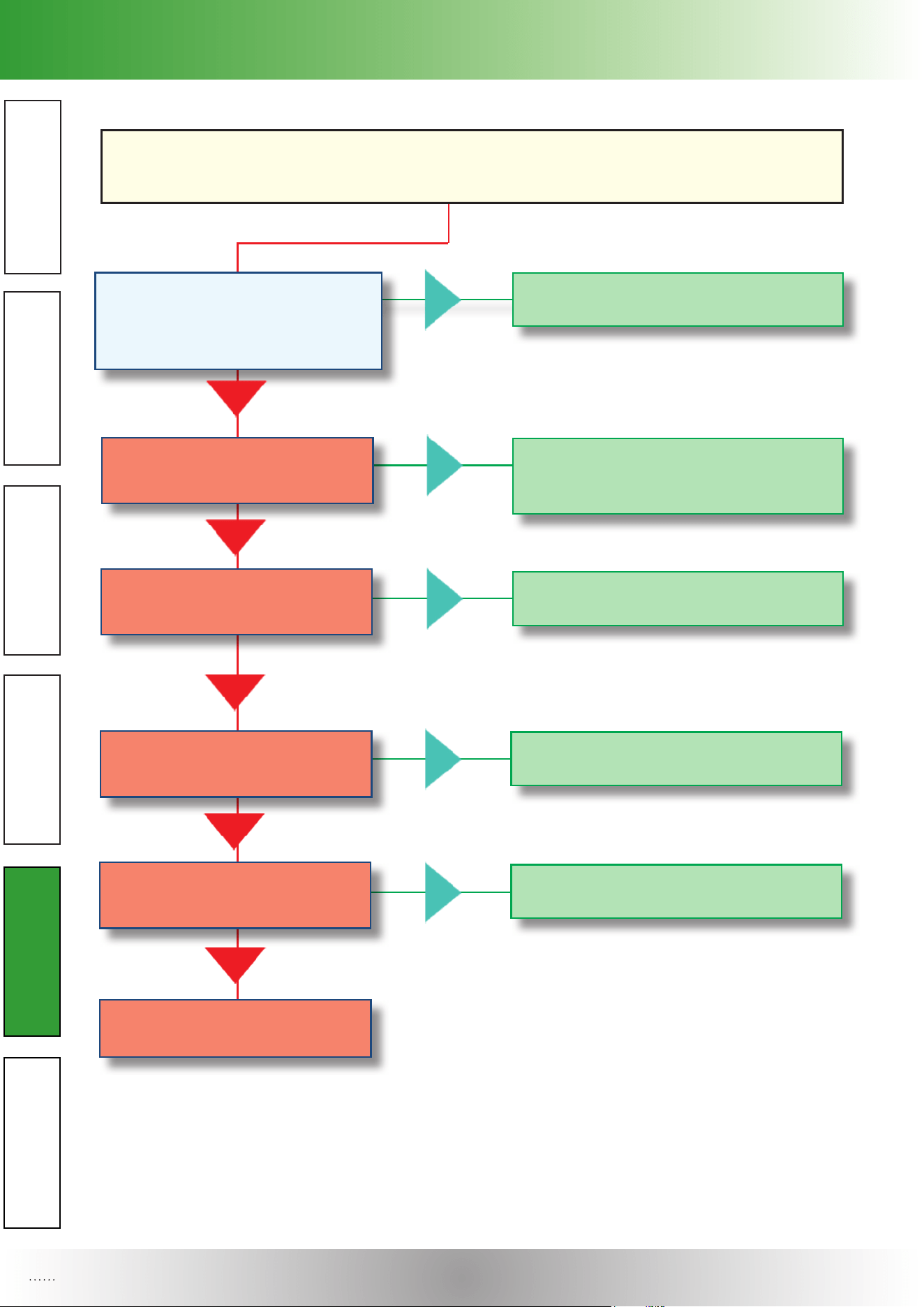
TROUBLESHOOTING
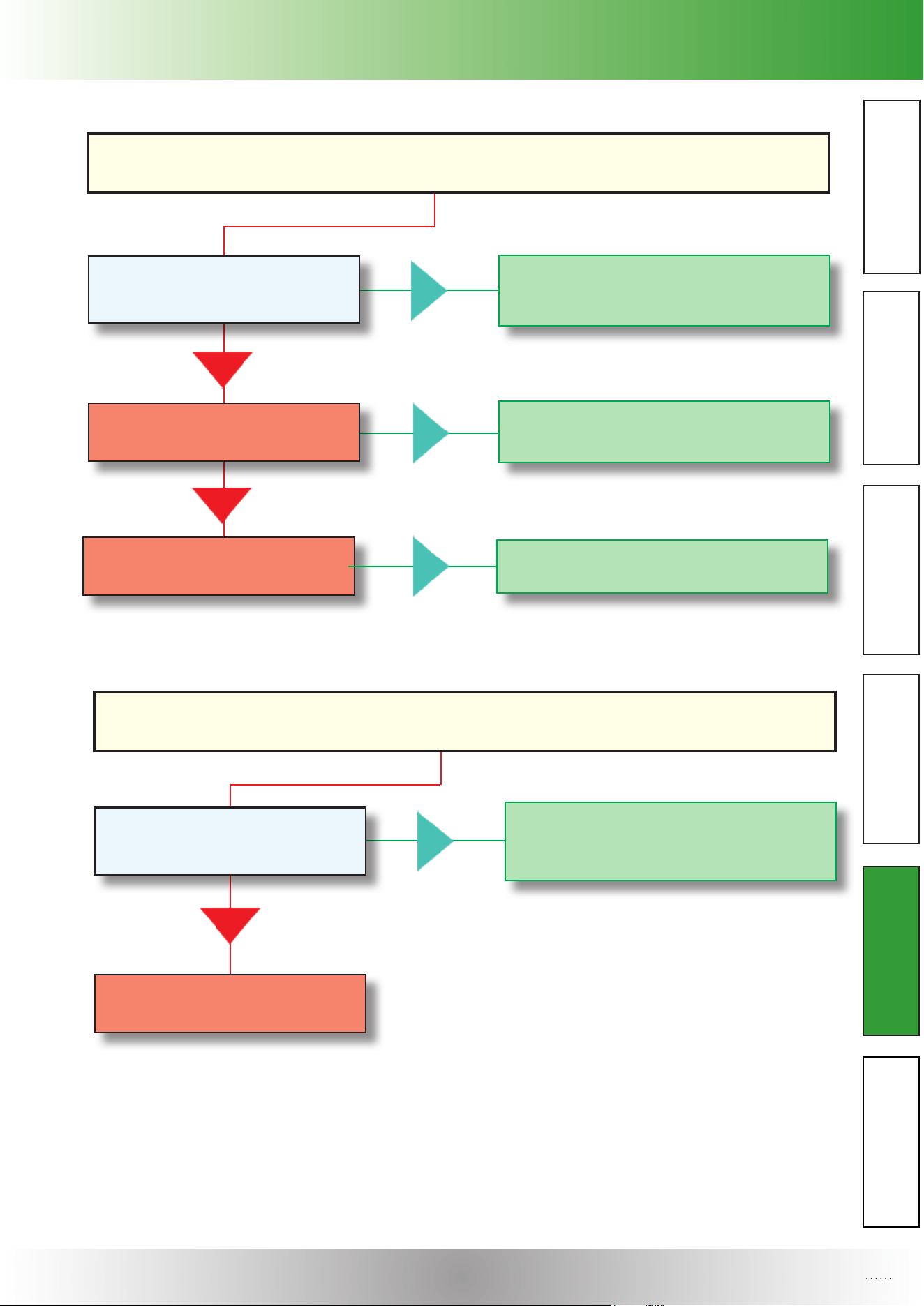
MACHINE DOES NOT OPERATE OR OPERATION IS INTERRUPTED
THE MAIN SWITCH IS IN THE ON POSITION (1), THE POWER
WARNING LIGHT DOES NOT SWITCH ON.
R Troubleshooting – owchart
In fault conditions the machine may malfunction, as specied below:
The plug is noT inserTed in The
sockeT correcTly.
insert it CorreCtly.
yes
The sockeT is faulTy.
have it substituted by a qualified
teChniCian.
no
yes
no elecTric power in The neT-
work or in The sockeT.
CheCk that the disConneCting
switChes, all-pole (phase & neutral)
isolating switChes and residual Current
operated CirCuit breakers (Cut-outs) on
the eleCtriCal system, upstream of the
soCket, are Closed.
if not, before Closing them, make sure
that no one is Carrying out eleCtriCal
repairs.
no
yes
a fuse designed To proTecT The
auxiliary elecTrical sysTem
has blown.
identify and eliminate the Cause of
the overload and substitute the
blown fuse with another having the
same speCifiCations and level of pro-
teCtion. ContaCt the teChniCal assis-
tanCe serviCe.
yes
no
no
The power cable is damaged.
Cut off the eleCtriCity supply to the soCket
by opening the disConneCting switCh up-
stream of it, then disConneCt the plug and
ContaCt the teChniCal assistanCe serviCes.
yes
DO NOT TOUCH DAMAGED ELECTRIC
CABLES BEFORE CUTTING OFF THE
ELECTRICITY SUPPLY!
conTacT The Technical assisTance
service.
no
Section 5 : Troubleshooting
OPERATOR’S MANUAL
22
TROUBLESHOOTING
CREAM COMES OUT LIQUID WET OR FLABBY.
The air-regulaTor knob is Too
TighT.
inCrease the opening by rotating
CounterCloCkwise, the hand-grip on a
higher number.
yes
cream has a high sugar con-
TenT or a low quanTiTy of faTs.The
cream is noT suiTable wiTh The
labyrinTh.
no
yes
The air-valve is obsTrucTed.
no
Choose another kind of Cream.
yes
disassemble and Clean it as desCribed
in seCtions “F,G”.
The refrigeraTing sysTem is
damaged.
no
yes
ContaCt the teChniCal assistanCe
serviCe.
yes
no
yes
no
MACHINE REPEATEDLY TRIPS THE
ELECTRIC OVERLOAD SWITCHES OR BLOWS THE MAIN FUSES.
The capaciTy of The elecTrical sys-
Tem is noT sufficienT To power The
machine.
ContaCt the teChniCal assistanCe
serviCe.
The elecTrical specificaTions of The
overload swiTches or fuses are noT
suiTable.
machine inTernal faulT.
no
ContaCt the teChniCal assistanCe
serviCe.
ContaCt the teChniCal assistanCe
serviCe.
yes
Section 5 : Troubleshooting
OPERATOR’S MANUAL
OPERATOR’S MANUAL
23
TROUBLESHOOTING
NO CREAM DISPENSING
developmenT of buTTer on The
labyrinTh and/or in The cream
dispenser.
disassemble labyrinth and/or Cream
dispenser and Clean it as desCribed
in seCtions “F,G”.
yes
The cream aspiraTion Tube is
obsTrucTed.
no
yes
The pump is damaged.
no
disassemble the Cream aspiration
tube and Clean it as desCribed in
seCtions “F,G”.
yes
ContaCt the teChniCal assistanCe
serviCe.
TENDENCY AT SHOOT OUT AIR AND/OR CREAM.
air-valve is excessively ope-
ned.
Close the opening by rotating
CloCkwise the air-regulator knob
of a lower number.
yes
ContaCt the teChniCal assistanCe
serviCe.
no
Section 5 : Troubleshooting
OPERATOR’S MANUAL
24
TROUBLESHOOTING
no
yes
no
AIR COOLING IS INSUFFICIENT OR IT SWITCHES OFF IN A FAULTY WAY
There are obsTrucTions in fronT
of The air condenser grilles,
or The disTance is less Than re-
quired in sec. b “specificaTions”.
yes
The TemperaTure in The working
environmenT is Too high and There
is insufficienT condensaTion.
The air condenser is blocked.
restore the operating temperature, as
indiCated in the manual in seC. b “ speCi-
fiCations”.
yes
ask the teChniCal assistanCe serviCe
for Cleaning.
yes
no
yes
no
no
The air condenser fan is faulTy.
faulT in The refrigeraTion sysTem
or conTrol elecTronics.
no
ContaCt the teChniCal assistanCe
serviCe.
ContaCt the teChniCal assistanCe
serviCe.
conTacT The Technical assisTance
service.
no
restore the minimum distanCe required.

Section 5 : Troubleshooting
OPERATOR’S MANUAL
OPERATOR’S MANUAL
25
TROUBLESHOOTING
PART
Section 6 : Replacement Parts
OPERATOR’S MANUAL
26
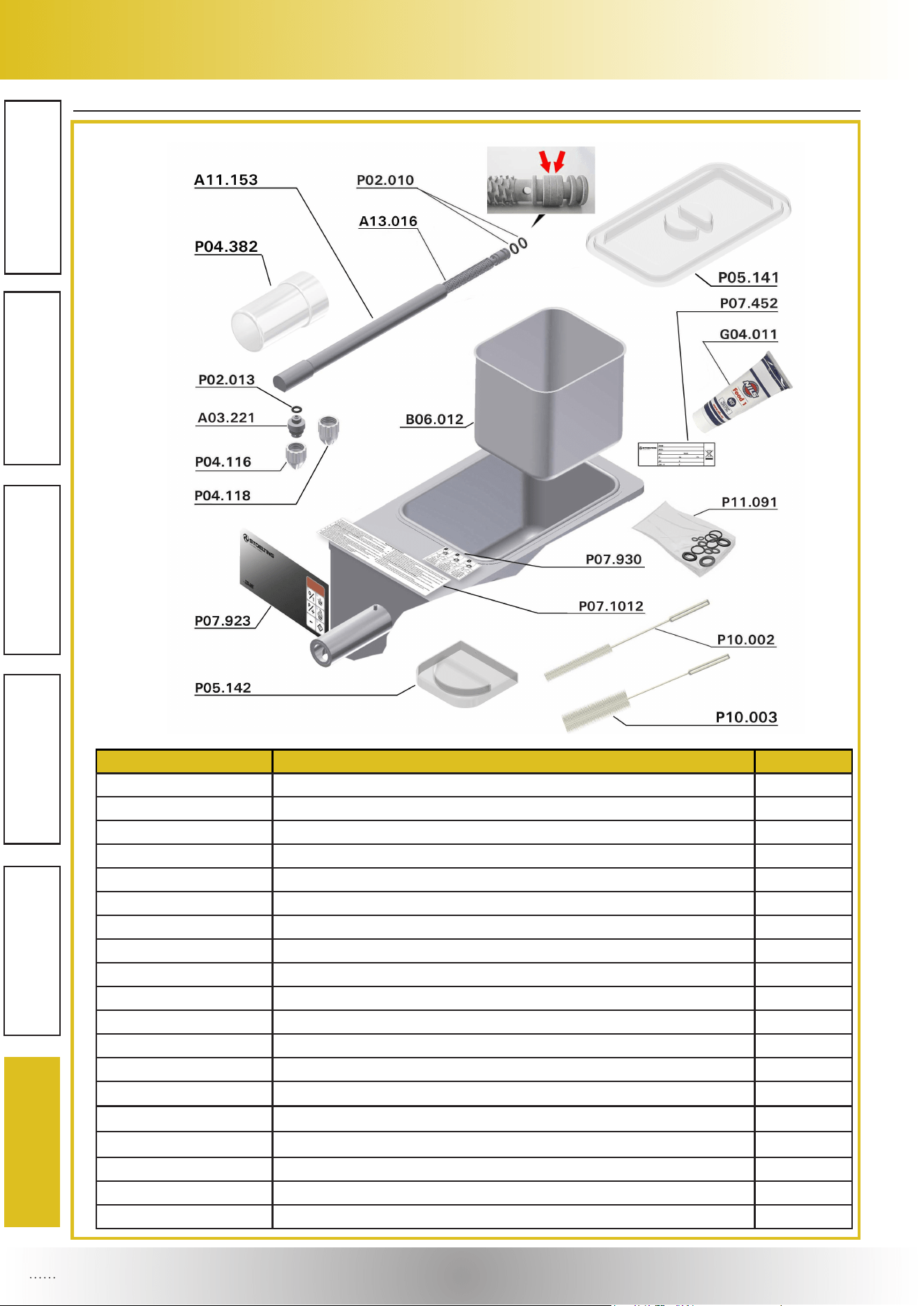
S Replacement Parts:
Part Number Description Quantity
A03.221 CREAM DISPENSER 1
A11.153 LABYRINTH TUBE 1
A13.016 LABYRINTH 1.8 1
B06.012 CREAM CONTAINER 1
G04.011 EP1 FOOD GREASE TUBE 1
P02.010 GASKET O-RING 3043 2
P02.013 GASKET O-RING 2050 1
P04.116 WHITE NOZZLE 1
P04.118 WHITE NOZZLE 1
P04.382 DISPENSING FAUCET 1
P05.141 LID 1
P05.142 DRIP TRAY 1
P07.452 TECHNICAL DATA LABEL 1
P07.923 FRONT SIDE LABEL 1
P07.930 AIR REGULATOR USE DECAL 1
P07.1012 CLEANING LABEL 1
P10.002 CLEANING BRUSH D.16 x 301 1
P10.003 CLEANING BRUSH D.45 x 350 1
P11.091 SPARE PARTS KIT 1
Section 6 : Replacement Parts
OPERATOR’S MANUAL
OPERATOR’S MANUAL
27
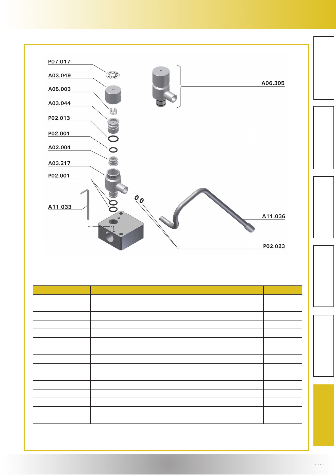
PART
Part Number Description Quantity
A02.004 VALVE 1
A03.044 VALVE SOCKET 1
A03.049 AIR REGULATOR KNOB 1
A03.217 AIR REGULATOR BODY 1
A05.003 AIR REGULATION SPRING (DIM D21800) 1
A06.305 AIR REGULATOR ASSEMBLY 1
A11.033 FIXING ROD 1
A11.036 CREAM ASPIRATION TUBE 1
P02.001 GASKET O-RING 2037 3
P02.013 GASKET O-RING 2050 1
P02.023 GASKET O-RING 5x1,5 2
P07.017 AIR REGULATOR DECAL 1

updated 04-02-2020

