
20 55
56
62
41
43
64
35 36 37
38 39
63
44 45 46
48 49
67
53
54
65
11
15
66
22 23
31 33
61
35
36
37
38
39
40
21
42
43
44
45
46
51
50
49
48
47
1 2 4 5 6 7 34
52
53
54
34
21
57 59 58
55
25
24
56
16
17
18
15
19
9
10
11
20
22
12
13
14
6
8
29
31
32
28 27 26
30
33
21 23
3
41
60
CORDLESS 5-3/8" METAL CUTTING SAW
2682-20
C74A
54-40-7060
SEE REVERSE SIDE
Sept. 2013
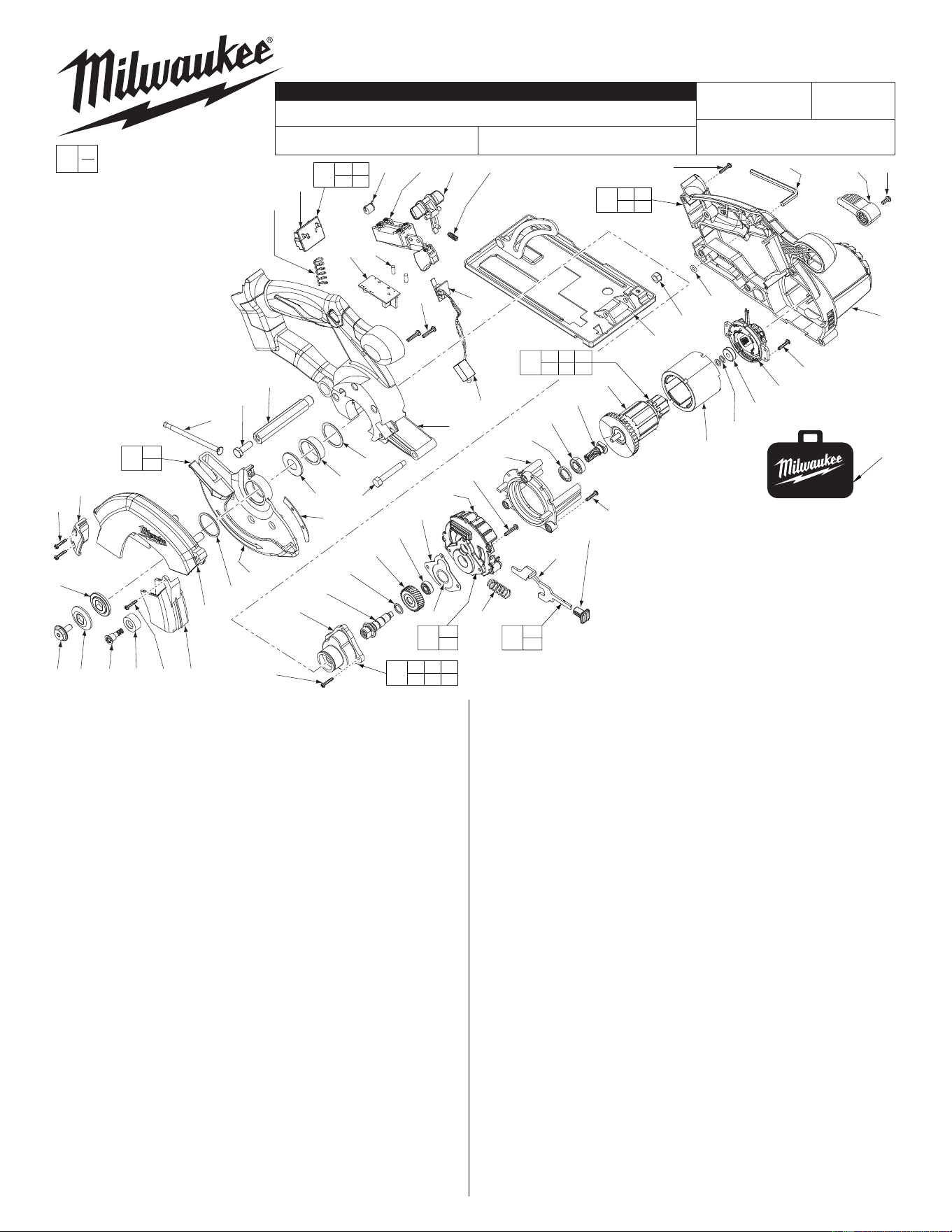
FIG. PART NO. DESCRIPTION OF PART NO REQ.
1 45-04-1020 Hex Flange Blade Screw (1)
2 43-34-0685 Outer Blade Flange (1)
3 43-34-0680 Inner Blade Flange (1)
4 45-04-1060 Bumper Screw (1)
5 42-38-0222 Rubber Bumper (1)
6 05-81-1420 M3 x 10 Pan Hd. T-10 Screw (3)
7 44-06-0200 Transparent Window (1)
8 42-92-1290 Guard Cover (1)
9 43-54-0950 Upper Guard (1)
10 34-60-0630 Retaining Ring (1)
11 --------------- Lower Guard (1)
12 40-50-1710 Spring (1)
13 06-75-5860 1/4" x 20 UNC Screw (1)
14 42-18-0400 Hexagon Bar (1)
15 --------------- Lower Guard Plate (1)
16 45-88-3095 Dust Seal (1)
17 45-22-0515 Sleeve (1)
18 45-88-3220 Washer (1)
19 42-32-0425 Shoulder Bolt (1)
20 --------------- Housing Support (1)
21 06-82-2025 M3.5 x 15 Pan Hd. Plastite Screw (12)
22 --------------- LED Assembly (1)
23 --------------- Micro Switch with PCB (1)
24 14-74-0450 Shoe Assembly (1)
25 06-57-1100 Lock Nut (1)
26 40-50-1760 Lock Out Spring (1)
27 44-20-0720 Switch Lock Out (1)
28 23-66-1000 Switch (1)
29 22-74-0515 Diode (1)
30 45-30-0255 Rubber Pin (2)
31 --------------- Battery Terminal Block (1)
32 40-50-1090 Terminal Block Spring (1)
33 --------------- PCB Assembly (1)
34 05-81-1170 M3.0 x 12 Screw (6)
35 --------------- Gear Housing Cover (1)
36 --------------- Spindle (1)
37 --------------- Retaining Ring (1)
38 --------------- Spindle Gear (1)
39 --------------- Ball Bearing (1)
REVISED BULLETIN
SERVICE PARTS LIST
BULLETIN NO.
WIRING INSTRUCTION
DATE
SPECIFY CATALOG NO. AND SERIAL NO. WHEN ORDERING PARTS
CATALOG NO.
MILWAUKEE ELECTRIC TOOL CORPORATION
13135 W. LISBON RD., BROOKFIELD, WI 53005
Drwg. 8
STARTING
SERIAL NO.
FIG. PART NO. DESCRIPTION OF PART NO REQ.
40 43-44-1350 Gasket (1)
41 --------------- Gearcase (1)
42 42-14-0500 Baffl e (1)
43 45-06-1050 Rubber Seal (1)
44 02-04-1920 Ball Bearing (1)
45 --------------- Armature Pinion (1)
46 --------------- Armature (1)
47 18-10-0300 Service Field (1)
48 45-88-3225 Washer (2)
49 02-04-1930 Ball Bearing (1)
50 22-22-0760 Brush Card Assembly (1)
51 06-82-6350 M3 x 16 Screw (4)
52 40-50-1740 Spring (1)
53 --------------- Spindle Lock (1)
54 --------------- Lock Button (1)
55 34-40-4480 O-Ring (1)
56 --------------- Housing Cover (1)
57 49-96-0080 3/16" Hex Key (1)
58 06-82-5314 10-24 x 1/2" Pan Hd. Tapt. T-25 Screw (1)
59 44-10-0625 Depth Lever (1)
60 34-40-2425 O-Ring (1)
61 23-66-3110 Micro-Switch/PCBA/Term. Block Assy. (1)
62 31-44-2295 Housing Assembly (1)
63 43-78-0590 Hub Assembly (1)
64 28-14-1110 Gearcase Assembly (1)
65 44-20-0700 Spindle Lock Assembly (1)
66 28-41-1180 Lower Guard Assembly (1)
67 16-01-1170 Service Armature Assembly (1)
68 48-55-3500 Contractor Bag (1)
12-20-2682 Service Nameplate (Not Shown) (1)
EXAMPLE:
Component Parts (Small #)
Are Included When Ordering
The Assembly (Large #).
0
00
Functionally check switch lock-out #27 by
attempting to turn on tool by applying a
reasonable amount of force, up to 8 lbs., to
the switch trigger #28. The tool must not turn
on. Release trigger. Actuate the lock-out lever
and apply a reasonable amount of force to the
switch trigger. The tool must turn on. While the
trigger is still in the "ON" position, release the
lock-out. Release the trigger. The tool must
stop and the lock-out lever must again prevent
the actuation of the switch. Repeat the switch
check two more times.
Functionally check the lower guard #11, with the saw set
at full depth. Place the saw upside down with the shoe
horizontal. Fully retract the guard and then release it.
The guard must return briskly.
LUBRICATION:
Type 'Y' Grease, No. 49-08-5270
Liberally coat the teeth of the
Armature Pinion (45).
Lightly coat the bearing bores
of the Gearcase (41) prior to
installing bearings (39 & 44).
Fill back end of Gear Housing
Cover (35) with grease, making
sure that the teeth of Gear (38)
are completely covered.
68
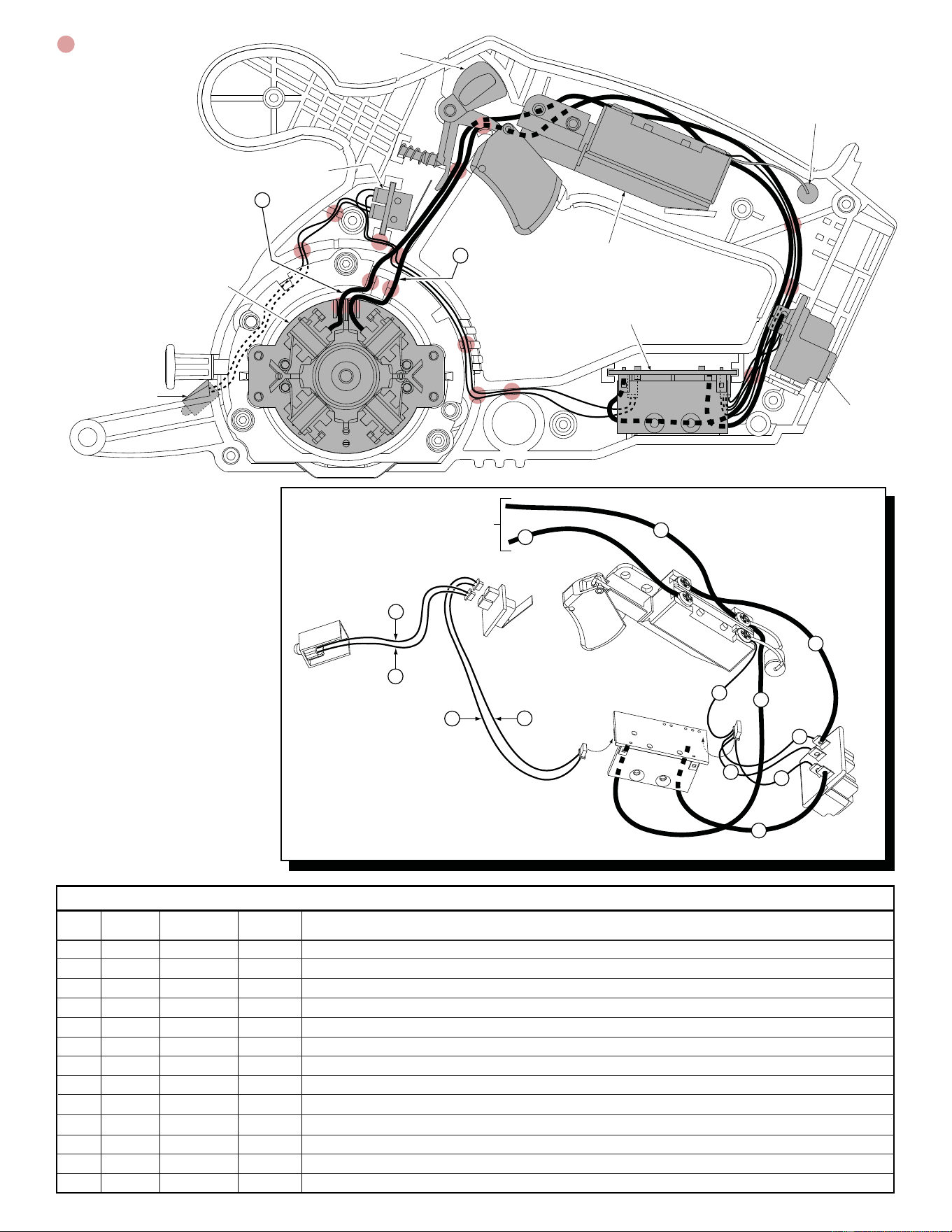
1 Black 22-22-0760 ----- Component of brush card assy. Route to bottom right position on switch with # 4, under diode terminal.
2 Red 22-22-0760 ----- Component of the brush card assembly. Route to the top left position on switch.
3 Red ----- ----- Component of the terminal block assembly. Route to top right position on switch.
4 Brown ----- ----- Component of the PCB assembly. Route to bottom right position on switch With #1, under diode terminal.
5 Black ----- ----- Component of the PCB assembly that is soldered to the battery terminal block as shown.
6 White ----- ----- Component of 4 pin connector. Route to bottom left position on switch under diode terminal.
7 Red ----- ----- Component of 4 pin connector. Soldered to battery terminal block with #3 as shown.
8 Yellow ----- ----- Component of 4 pin connector. Soldered to battery terminal block as shown.
9 Blue ----- ----- Component of 4 pin connector. Soldered to battery terminal block as shown.
10 Blue ----- ----- Comp. of two 2 pin connectors. Attach to PCB at one end and the top position of micro switch at other.
11 Yellow ----- ----- Comp. of two 2 pin connectors. Attach to PCB at one end and the top position of micro switch at other.
12 Red ----- ----- Component of LED assembly. Attach connector block to bottom position of micro switch as shown.
13 White ----- ----- Component of LED assembly. Attach connector block to bottom position of micro switch as shown.
= WIRE TRAPS
Micro Switch
LED
Assembly
Brush Card
Assembly
PCB Assembly
Switch
Lock-Out
On/Off Switch
Diode
22-74-0515
Battery
Terminal
Block
2
12
10
Red
Wires From
Brush Card
Assembly
1
Black
3
Red
Diode
4
Brown
5
Black
6
White
7
Red
8
Yellow
9
Blue
11
Yellow
Blue
13
Red
White
LED
Assembly
Micro
Switch
On/Off
Switch
PCB
Assy.
Battery
Term. Block
2 Red
1 Black
AS AN AID TO REASSEMBLY,
TAKE NOTICE OF WIRE ROUTING
AND POSITION IN WIRE GUIDES
AND TRAPS WHILE DISMANTLING
TOOL.
BE CAREFUL AND AVOID PINCHING
WIRES BETWEEN HANDLE HALVES
WHEN ASSEMBLING.
Terminals, Connectors and 1 or 2 End Wire Preparation
Wire
Color
Origin or
Gauge
Wire
No.
Length
WIRING SPECIFICATIONS