
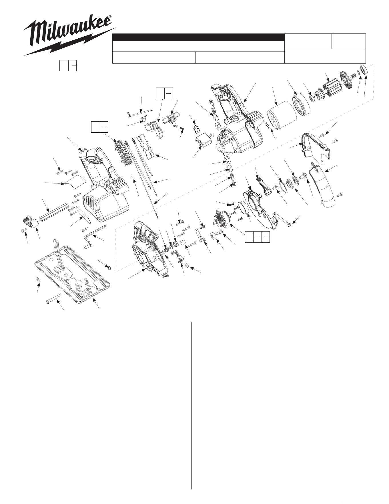
CORDLESS METAL CUTTING SAW
0740-20
A94C
54-40-7051
SEE REVERSE SIDE
Oct. 2017
FIG. PART NO. DESCRIPTION OF PART NO REQ.
1 02-04-1212 Ball Bearing (1)
2 02-04-5130 Ball Bearing (1)
3 02-50-1640 Needle Bearing (1)
4 06-57-1100 Lock Nut (1)
5 06-75-1010 Left Hand Screw (1)
6 06-75-5860 1/4-20 x 3/4 Screw (1)
7 06-82-5285 6-32 X 1/2 TT TORX Pan (5)
8 06-82-5314 10-24X1/2 Pan Tap TX SC (5)
9 06-82-7470 Screw 6 X 11/16 Plastite (8)
10 06-82-7475 Screw 6 X 7/8 Plastite (4)
11 06-82-9685 Shoulder Bolt (1)
12 10-20-2880 Logo Label (1)
13 12-20-1250 Service Nameplate (1)
14 14-74-0400 Shoe (1)
15 16-01-0300 Armature (1)
16 18-01-2000 Field (1)
17 22-09-1075 Circuit Board (1)
18 22-18-1245 Brush Assembly - Black (1)
19 22-18-1250 Brush Assembly - Red (1)
20 22-20-0425 Brush Tube (2)
21 22-32-0420 Brush Spring Clip (2)
22 22-36-0230 30 Amp Overload Protect (1)
23 22-56-0975 Connector Block Assembly (1)
24 22-74-0510 Diode (1)
25 23-28-0175 LED (1)
26 23-66-1005 Service Switch (1)
27 23-94-2680 Lead Wire Assembly - Red (1)
28 23-94-2690 Lead Wire Assembly - Black (1)
29 23-94-2700 Lead Wire Breaker & Switch (1)
30 28-14-0795 Gearcase (1)
31 28-20-1174 Upper Guard Cover (1)
32 28-41-0945 Upper Guard Window (1)
33 28-41-1090 Lower Guard (1)
34 31-05-0350 Bae (1)
REVISED BULLETIN
SERVICE PARTS LIST
BULLETIN NO.
WIRING INSTRUCTION
DATE
SPECIFY CATALOG NO. AND SERIAL NO. WHEN ORDERING PARTS
CATALOG NO.
MILWAUKEE ELECTRIC TOOL CORPORATION
13135 W. LISBON RD., BROOKFIELD, WI 53005
Drwg. 1
STARTING
SERIAL NO.
EXAMPLE:
Component Parts (Small #) Are Included
When Ordering The Assembly (Large #).
FIG. PART NO. DESCRIPTION OF PART NO REQ.
35 ------------- Connector Block Cover (1)
36 31-15-0601 Gear Case Cover (1)
37 31-44-2040 Handle Half - Right (1)
38 31-44-2046 Handle Half - Left (1)
39 32-75-1371 Spindle Gear (1)
40 34-40-4480 O-Ring (1)
41 34-60-0860 Retaining Ring External (1)
42 34-60-0920 Retaining Ring External (2)
43 38-50-1160 Spindle (1)
44 40-50-0045 Guard Spring (1)
45 40-50-0350 Lock Out Spring (1)
46 40-50-8041 Spring (1)
47 40-50-8745 Brush Spring (2)
48 42-38-0224 Bumper (1)
49 42-42-1025 Switch Lock Out (1)
50 42-42-1030 Spindle Lock Button (1)
51 43-34-0795 Outer Blade Flange (1)
52 43-34-0920 Inner Blade Flange (1)
53 43-72-0600 LED Holder (1)
54 44-10-0420 Guard Lever (1)
55 44-10-0430 Depth Lever (1)
56 44-20-0650 Spindle Lock (1)
57 44-66-0845 Spindle Lock Plate (1)
58 45-04-0485 Bumper Screw (1)
59 45-06-0720 Felt Seal (1)
60 45-08-0395 Depth Shaft (1)
61 45-88-1515 Washer Flat 1/4 (1)
62 45-88-5615 Wave Spring Washer (1)
63 49-96-0080 3/16” Hex Key (1)
64 14-46-2570 Spindle and Gear Assembly (1)
65 45-14-0015 Sleeve Ring (1)
0
00
Functionally check the lower
guard (33), with the saw set
at full depth of cut. Place the
saw upside down with the
shoe horizontal. Fully retract
the guard and then release it.
The guard must return briskly.
Apply 3.0 grams of "Y" grease, No. 49-08-5270
to gear bore of gearcase #30. Direct grease
toward the pinion end of the armature.
Applyalightlmoflubricanttothebearingbore
of the gearcase before assembling the
armature/bearing.
NOTE:
Remove brush tubes (20) prior to removing armature
assembly (15) from left handle halve (38).
Install brush tubes (20) into left handle halve (38)
only after armature assembly (15) has been
secured into left handle halve (38).
FIG. NOTE:
25, Disconnect red and black LED leads prior to removing
30, 37 gearcase from right handle half.
16,38 Placeeldinlefthandlehalfwithchamferedendinrst.Line
up slot in groove.
15, Install wave spring washer into left handle half bearing bore
37, 62 prior to installing armature assembly.
23,35 Assemble(snapt)connectorblockcoverwithconcaveside
facing connector block.
55
61
11
14
30
4
53
25
3
10
7
57
48
58
7
33
54
44
8
41
52
51
5
32
31
8
1
42
15
2
34
16
62
38
21
47
18
20
22
17
19
49
24
29
45
35
28
27
40
37
63
12
13
9
60
8
50
56
46
59
24
26
35
23
42
64
43
36 39
54-40-7050
«
65
RED
BLACK
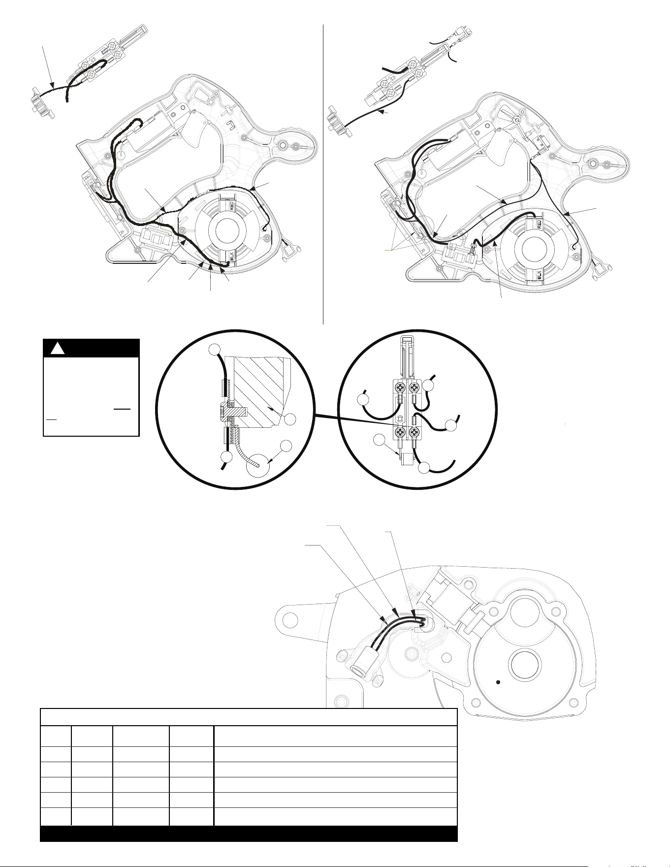
LED WIRE ROUTING
THROUGH LED HOLDER
A
ND GEARCASE
Terminals, Connectors and 1 or 2 End Wire Preparation
Wire
Color
Origin or
Gauge
Wire
No.
Length
WIRING SPECIFICATIONS
19 Red 22-18-1250 ----- Carbon brush assembly.
18 Black 22-18-1245 ----- Carbon brush assembly.
27 Red 23-94-2680 ----- Leadwire assembly.
28 Black 23-94-2690 ----- Leadwire assembly.
22-74-0510 ----- Diode assembly.
BULK LEAD WIRE - BULLETIN NO. 58-01-0003
WARNING
SWITCH AND DIODE
ARE POLARITY
SENSITIVE
If wired incorrectly,
switch and diode will
be damaged and
destroyed!
!
Functionally check switch
lock-out #49 by attempting
to turn on tool by applying a
reasonable amount of force,
up to 8 lbs., to the switch
trigger #26. The tool must
not turn on. Release trigger.
Actuate the lock-out lever and
apply a reasonable amount
of force to the switch trigger.
The tool and LED must turn
on. While the trigger is still in
the "ON" position, release the
lock-out. Release the trigger.
The tool and LED must stop
and the lock-out lever must
again prevent the actuation of
the switch. Repeat the switch
check two more times.
TO
POSITIVE
BATTERY
CONNECTION
BLACK
BLACK
TO NEGATIVE
BATTERY
CONNECT-
ION
ALL TERMINALS
MUST BE
ORIENTED AS
SHOWN IN
THESE VIEWS.
SWITCH DETAIL
SWITCH
BACK VIEW
18
28
24
DIODE
BLACK
BRUSH
ASSEMBLY
BLACK
LEADWIRE
ASSY.
26
SWITCH
24
DIODE
BAND SIDE
28
18
27
29
TO
OVERLOAD
PROTECTOR
RED
RED
TO BOTTOM
BRUSH TUBE
Red brush
assembly #19
Black leadwire
#28 to connector
Connector
block #23
Black brush lead
Black leadwire
#28 to connector
Black LED
lead #25
Black brush
Assembly #18
Terminal must be located between
"A" and "B" for both brushes
Negative (Black)
Wire Routing
B
A
To overload
protector
To connector
block or LED
To connector
block or LED
Red leadwire #27
to connector
Connector
block #23
Positive (RED)
Wire Routing
Wires may be
placed in any order
in these traps
Red lead #27
Red LED
lead #25
29
NOTE: Disconnect LED wiring
before removing gearcase.