P SIX DSP
MK2
6-Kanal Verstärker mit integriertem DSP
6-channel Amplier with integrated DSP
deutsch / english

Sehr geehrter Kunde,
Wir gratulieren Ihnen zum Kauf dieser hochwer-
tigen HELIX Digitalendstufe.
Audiotec Fischer setzt mit der HELIX
P SIX DSP MK2 neue Maßstäbe im Bereich der
Verstärkertechnik. Dabei protieren Sie als Kunde
direkt von unserer nahezu 30-jährigen Erfahrung in
der Forschung und Entwicklung von Audiokompo-
nenten. Diese Endstufe wurde von uns nach neu-
esten technischen Erkenntnissen entwickelt und
zeichnet sich durch hervorragende Verarbeitung
und eine überzeugende Anwendung ausgereifter
Technologien aus.
Viel Freude an diesem Produkt wünscht Ihnen das
Team von
AUDIOTEC FISCHER
Allgemeines zum Einbau von HELIX-Kompo-
nenten
Um alle Möglichkeiten des Produktes optimal aus-
schöpfen zu können, lesen Sie bitte sorgfältig die
nachfolgenden Installationshinweise. Wir garantie-
ren, dass jedes Gerät vor Versand auf seinen ein-
wandfreien Zustand überprüft wurde.
Vor Beginn der Installation unterbrechen Sie
den Minusanschluss der Autobatterie.
Wir empfehlen Ihnen, die Installation von einem
Einbauspezialisten vornehmen zu lassen, da der
Nachweis eines fachgerechten Einbaus und An-
schlusses des Gerätes Voraussetzung für die Ga-
rantieleistungen sind.
Installieren Sie Ihren Verstärker an einer trocke-
nen Stelle im Auto und vergewissern Sie sich, dass
der Verstärker am Montageort genügend Kühlung
erhält. Montieren Sie das Gerät nicht in zu kleine,
abgeschlossene Gehäuse ohne Luftzirkulation
oder in der Nähe von wärmeabstrahlenden Teilen
oder elektronischen Steuerungen des Fahrzeuges.
Im Sinne der Unfallsicherheit muss der Verstärker
professionell befestigt werden. Dieses geschieht
über Schrauben, die in eine Montageäche ein-
geschraubt werden, die wiederum genügend Halt
bieten muss.
Bevor Sie die Schrauben im Montagefeld befesti-
gen, vergewissern Sie sich, dass keine elektrischen
Kabel und Komponenten, hydraulische Bremslei-
tungen, der Benzintank etc. dahinter verborgen
sind. Diese könnten sonst beschädigt werden. Ach-
ten Sie bitte darauf, dass sich solche Teile auch in
der doppelten Wandverkleidung verbergen können.
Allgemeines zum Anschluss des P SIX DSP MK2
Verstärkers
Der Verstärker darf nur in Kraftfahrzeuge eingebaut
werden, die den 12 V / 24 V-Minuspol an Masse
haben. Bei anderen Systemen können der HELIX
Verstärker und die elektrische Anlage des Kfz be-
schädigt werden. Die Plusleitung für die gesamte
Anlage sollte in einem Abstand von max. 30 cm von
der Batterie mit einer Hauptsicherung abgesichert
werden. Der Wert der Sicherung errechnet sich aus
der maximalen Stromaufnahme der Car-Hi Anlage.
Verwenden Sie zum Anschluss des Verstärkers
an die Stromversorgung des Fahrzeugs aus-
schließlich geeignete Kabel mit ausreichen-
dem Kabelquerschnitt. Die Sicherungen im
Verstärker dürfen nur mit den gleichen Werten
(3 x 20 A) ersetzt werden, um eine Beschädi-
gung des Gerätes zu verhindern. Höhere Werte
können zu gefährlichen Folgeschäden führen!
Die Kabelverbindungen müssen so verlegt sein,
dass keine Klemm-, Quetsch- oder Bruchgefahr be-
steht. Bei scharfen Kanten (Blechdurchführungen)
müssen alle Kabel gegen Durchscheuern gepols-
tert sein. Ferner darf das Versorgungskabel niemals
mit Zuleitungen zu Vorrichtungen des Kfz (Lüfter-
motoren, Brandkontrollmodulen, Benzinleitungen
etc.) verlegt werden.
Herzlichen Glückwunsch!
2
Allgemeine Hinweise
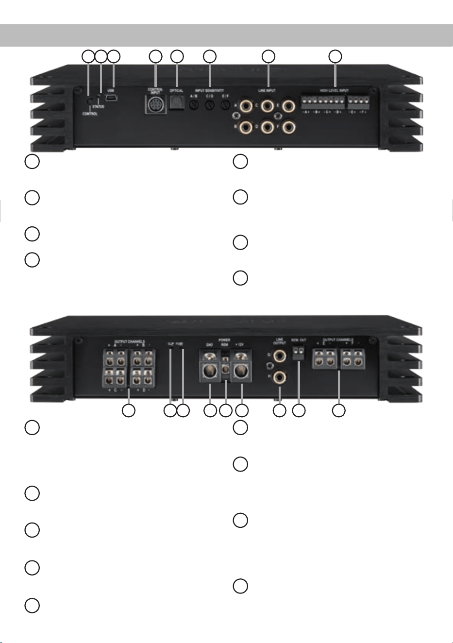
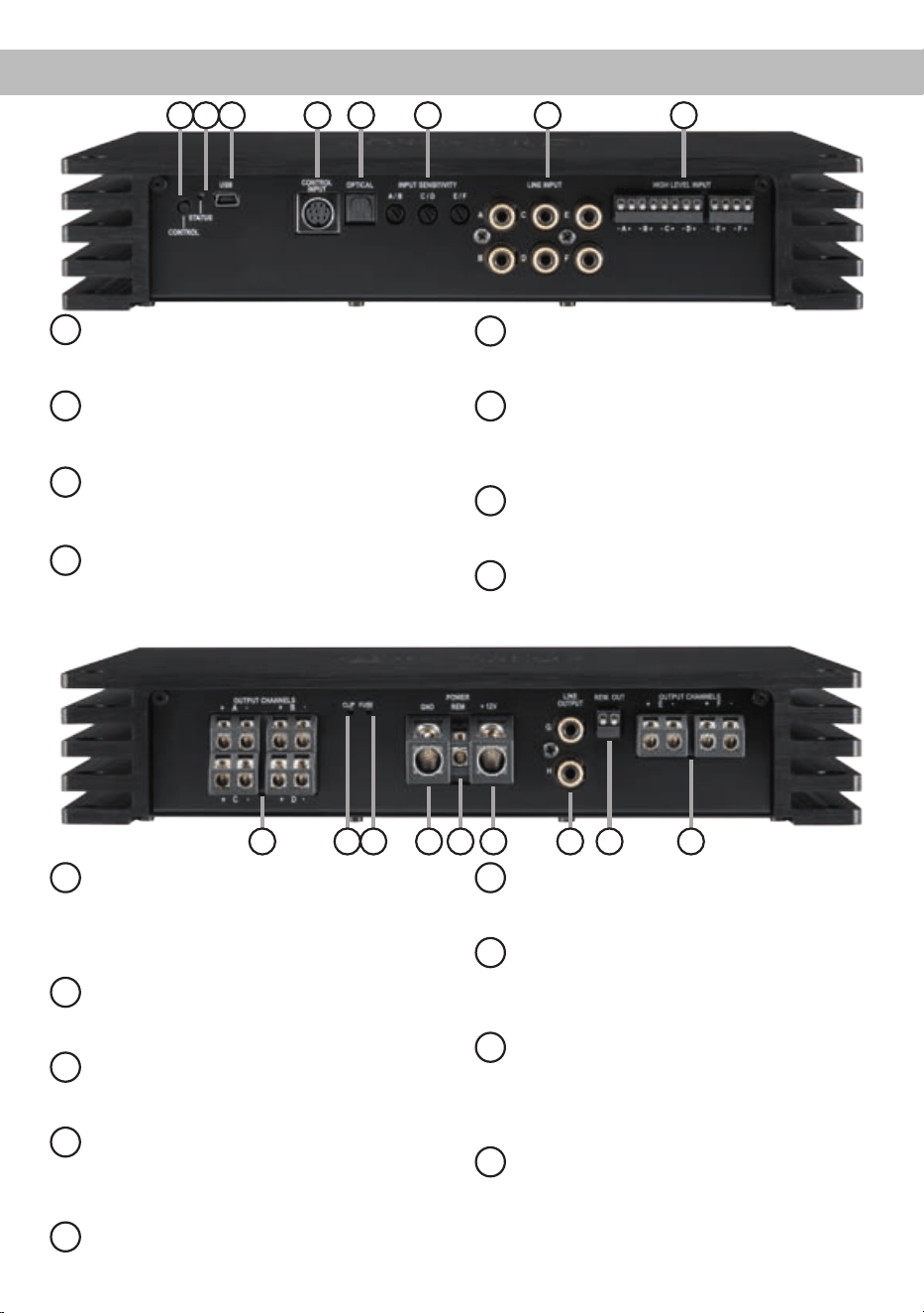
Anschluss- und Bedienelemente
3
9
Output Channels A - D
Lautsprecherausgänge A - D für den An-
schluss von Lautsprechersystemen. Die Ka-
näle A und B dürfen minimal mit 4 Ohm bela-
stet werden, alle anderen Kanäle sind 2 Ohm
stabil.
10
Clipping LED
Diese LED leuchtet rot, wenn einer der Ana-
logeingänge übersteuert wird.
11
Fuse
LED zur Anzeige einer defekten Sicherung
im Gerät.
12
GND
Anschluss des Massekabels (Minuspol der
Batterie oder Fahrzeugchassis).
13
REM
Anschluss für die Remoteleitung.
14
+12 V / +24 V
Anschluss für das Versorgungsspannungs-
kabel +12 V / +24 V der Batterie.
15
Line Output
Vorverstärkerausgänge zum Anschluss
weiterer Verstärker. Zur Einschaltung wei-
terer Verstärker muss der Remote-Ausgang
(Rem Out) verwendet werden.
16
Rem Out
Der Remote-Ausgang dient zum Einschalten
weiterer Verstärker. Dieser Ausgang muss
bei Verwendung des Line Output / der Cinch-
Ausgänge genutzt werden. Beide Anschlüs-
se sind intern parallel geschaltet.
17
Output Channels E - F
Lautsprecherausgänge E und F für den An-
schluss von Lautsprechersystemen. Diese
Kanäle sind 2 Ohm stabil.
9 10 11 12 13 14 15 16 17
1 432 5 6 7 8
1
Control Taster
Dient zum Umschalten der Sound Setups
oder zum Resetten des Gerätes.
2
Status LED
Die Status LED zeigt den Betriebszustand
und den ausgewählten Speicherbereich an
.
3
USB Eingang
Dient zum Anschluss an den Computer.
4
Control Input
Multifunktionsanschluss - dient zum An-
schluss einer Fernbedienung und weiterem
HELIX Zubehör.
5
Optical Input
Optischer Eingang im SPDIF-Format für
digitale Stereosignale.
6
Input Sensitivity
Regler zum Einstellen der Eingangsempnd-
lichkeit des Line und Highlevel Inputs für die
einzelnen Stereo-Kanäle.
7
Line Input
Cinch-Eingänge zum Anschluss eines
Vorverstärkersignals.
8
Highlevel Input
Hochpegel-Lautsprechereingang zum An-
schluss von Werksradios oder Radios ohne
Vorverstärkerausgänge.

1
Control Taster
Mit Hilfe des Control Tasters lässt sich zwischen
den Speicherbereichen eins und zwei umschalten.
Zum manuellen Umschalten der zwei Setups muss
der Control Taster eine Sekunde lang gedrückt wer-
den. Der Umschaltvorgang wird durch einmaliges
rotes Blinken der Status LED angezeigt. Wird der
Taster länger als 5 Sekunden gedrückt, so wird
das Gerät resettet und der gesamte interne Spei-
cher gelöscht! Anschließend wird dies durch ein
rotes Dauerblinken der Status LED angezeigt.
Achtung: Nach dem Resetten des Gerätes kann
die HELIX P SIX DSP MK2 keine Audiosignale
mehr wiedergeben, bis ein neues Sound Setup ein-
gespielt wurde.
2
Status LED
Die Status LED zeigt das aktuell ausgewählte Se-
tup der HELIX P SIX DSP MK2 an. Leuchtet die
LED grün, ist Setup 1 geladen. Bei Setup 2 leuchtet
die LED orange. Sollte sich kein Setup im internen
Speicher benden, blinkt die LED rot. Sofern letz-
teres der Fall ist, muss über die DSP PC-Tool Soft-
ware ein neues DSP Setup eingespielt werden.
3
USB Eingang
Mit Hilfe dieses Eingangs wird der HELIX
P SIX DSP MK2 über das beiliegende Kabel mit
dem Computer verbunden und kann anschließend
über das DSP PC-Tool konguriert werden.
4
Control Input
Dieser Multifunktionseingang dient zum Anschluss
von HELIX Zubehörprodukten, wie beispielsweise
einer Fernbedienung, mit deren Hilfe diverse Funk-
tionen des Verstärkers gesteuert werden können.
Die Funktionalität muss je nach Typ der Fernbe-
dienung zuerst im „Device Conguration Menu“ der
DSP PC-Tool Software oder an der Fernbedienung
selbst konguriert werden.
5
Optical Input
Optischer Eingang im SPDIF-Format für den An-
schluss an Signalquellen mit digitalem Ausgang.
Die „Sampling Rate“ dieses Eingangs muss zwi-
schen 12 - 96 kHz liegen. Das Eingangssignal wird
automatisch an die interne Abtastrate angepasst.
Um diesen Eingang zu aktivieren und in der Laut-
stärke regeln zu können, wird eine optional erhält-
liche Fernbedienung empfohlen.
Hinweis:
Es können ausschließlich Stereosignale
und keine Dolby-codierten Daten verarbeitet werden!
6
Input Sensitivity
Mit Hilfe dieser Regler kann die Eingangsemp-
ndlichkeit der Kanäle an die Ausgangsspannung
des angeschlossenen Steuergerätes angepasst
werden. Diese Regler sind keine Lautstärkeregler,
sondern dienen nur der Anpassung. Die werkseitig
eingestellten Regelbereiche liegen bei 2 - 4 Volt für
den Cinch-Eingang (Line Input) und 5 - 10 Volt für
den Hochpegel-Eingang (Highlevel Input). Der Wer-
tebereich kann durch Umstecken eines Jumpers im
Geräteinneren verändert werden.
Achtung: Es ist zwingend notwendig die Eingangs-
empndlichkeit der P SIX DSP MK2 an die Signal-
quelle anzupassen, um Schäden am Verstärker zu
vermeiden.
7
Line Input
6-Kanal Vorverstärkereingang zum Anschluss von
Signalquellen, z.B. Radios. Die Eingangsemp-
ndlichkeit ist für alle Kanäle ab Werk auf 4 Volt
eingestellt (Linksanschlag). Es ist jedoch mög-
lich, die Empndlichkeit kanalpaarweise zwischen
2 und 4 Volt zu variieren. Durch Umstecken einer
Steckbrücke im Geräteinneren kann der Wertebe-
reich auf 4 – 8 Volt verändert werden.
8
Highlevel Input
6-Kanal Hochpegel-Lautsprechereingang. Mit Hilfe
dieses Eingangs kann der Verstärker direkt an die
Lautsprecherausgänge eines Werks-/ Nachrüstra-
dios oder eines Werksverstärkers angeschlossen
werden, sofern dieses / dieser nicht über Vorver-
stärkerausgänge verfügt. Die Eingangsempndlich-
Inbetriebnahme und Funktionen
4

5
keit ist für alle Kanäle ab Werk auf 10 Volt eingestellt
(Linksanschlag). Es ist jedoch möglich, die Emp-
ndlichkeit kanalpaarweise zwischen 5 - 10 Volt
zu variieren. Durch Umstecken einer Steckbrü-
cke im Geräteinneren kann der Wertebereich auf
10 - 20 Volt verändert werden. Zudem wird bei die-
ser Umschaltung auch die Eingangsimpedanz ver-
ändert, um einen optimalen Betrieb in Verbindung
mit Werksradios oder leistungsfähigen Werksver-
stärkern zu gewährleisten. Die Eingangsimpedanz
beträgt 13 Ohm im Einstellbereich 5 – 10 Volt und
64 kOhm im Einstellbereich 10 - 20 Volt.
Achtung: Verwenden Sie ausschließlich die mitge-
lieferten Stecker mit integrierten Schraubklemmen.
9
Output Channels A - D
Diese Anschlüsse dienen als Lautsprecheraus-
gänge der Kanäle A – D. Verbinden Sie niemals
die Lautsprecherkabel mit der Kfz-Masse (Fahr-
zeugkarosserie). Dieses kann Ihren Verstärker und
Ihre Lautsprecher zerstören. Achten Sie darauf,
dass alle Lautsprechersysteme phasenrichtig an-
geschlossen sind, d.h. Plus zu Plus und Minus zu
Minus. Vertauschen von Plus und Minus hat einen
Totalverlust der Basswiedergabe zur Folge. Der
Pluspol ist bei den meisten Lautsprechern gekenn-
zeichnet. Die Impedanz der Lautsprecher darf bei
den Kanälen A und B 4 Ohm nicht unterschreiten,
alle übrigen Kanäle können mit minimal 2 Ohm be-
lastet werden. Die Lautsprecherausgänge dürfen
nicht gebrückt werden.
10
Clipping LED
Diese LED leuchtet rot, wenn einer der sechs Line
Inputs oder Highlevel Inputs übersteuert wird. Die
LED hat keine Funktion bei Ansteuerung über die
Digitaleingänge. Sofern diese LED aueuchtet,
sollte die Eingangsempndlichkeit über die Poten-
tiometer abgesenkt werden, bis die LED erlischt.
11
Fuse
Sollten die Sicherungen im Inneren des Gerätes
durch eine Fehlfunktion zerstört werden, wird die-
ses durch das Aueuchten der roten LED ange-
zeigt. Bei normalem Betrieb leuchtet die LED grün.
12
GND
Das Massekabel sollte am zentralen Massepunkt
(dieser bendet sich dort wo der Minuspol der Bat-
terie zum Metallchassis des Kfz geerdet ist) oder an
einer blanken, von Lackresten befreiten Stelle des
Kfz-Chassis angeschlossen werden. Der empfohle-
ne Querschnitt beträgt mindestens 16 mm².
13
REM
Der Remote-Eingang dient zum Einschalten der
P SIX DSP MK2, sofern die am Highlevel-Eingang
angeschlossene Signalquelle die automatische
Einschaltung nicht aktiviert oder der Verstärker be-
wusst nur über ein Remote-Signal des REM ein- und
ausgeschaltet werden soll. Die Remoteleitung wird
mit dem Remote-Ausgang / Antennenanschluss
des Steuergerätes (Radio) verbunden. Dieser ist
nur aktiviert, wenn das Steuergerät eingeschaltet
ist. Somit wird der Verstärker mit dem Steuergerät
ein- und ausgeschaltet. Dieser Eingang muss nicht
belegt werden, wenn der Hochpegel-Lautspreche-
reingang (Highlevel Input) benutzt wird. Wie Sie die
automatische Einschaltung der P SIX DSP MK2
deaktivieren können, ist unter Punkt 7 „Kongurati-
on des Remote-Eingangs“ auf Seite 9 nachzulesen.
14
+12 V / +24 V
Der Verstärker kann sowohl mit +12 V als auch
+24 V betrieben werden. Das Versorgungskabel ist
am Pluspol der Batterie anzuschließen. Der emp-
fohlene Querschnitt beträgt mindestens 16 mm².
15
Line Output
2-Kanal Vorverstärkerausgang zum Anschluss von
zusätzlichen Verstärkern. Die maximale Ausgangs-
spannung beträgt 3 Volt. Wenn Sie diesen Aus-
gang verwenden, ist es zwingend erforderlich, den
Remote-Ausgang (Rem Out) zum Einschalten des /
der Verstärker/s zu verwenden, da ansonsten Stör-
signale auftreten können. Der Remote-Ausgang

6
Die HELIX P SIX DSP MK2 wird wie nachfolgend
beschrieben an das Autoradio angeschlossen.
Achtung: Für die Durchführung der nachfolgenden
Schritte werden Spezialwerkzeuge und Fachwissen
benötigt. Um Anschlussfehler und Beschädigungen
zu vermeiden, fragen Sie im Zweifelsfall Ihren Einbau
-
spezialisten und beachten Sie zwingend die allgemei-
nen Anschluss- und Einbauhinweise (siehe Seite 2).
1. Anschluss der Vorverstärkereingänge
Diese Eingänge können mit entsprechenden
Kabeln (RCA / Cinch-Kabel) an die Vorverstär-
ker- / Lowlevel- / Cinch-Ausgänge des Radios
angeschlossen werden. Im Verstärker lassen
sich die Signaleingänge über die DSP PC-Tool
Software frei den Lautsprecherausgängen bzw.
dem Line Out zuweisen. Die Einschaltautoma-
tik des Verstärkers funktioniert bei den Vorver-
stärkereingängen nicht, so dass der Remote-
Eingang (REM) zwingend belegt werden muss.
Achtung: Eine gleichzeitige Verwendung der
Highlevel- und Vorverstärkersignaleingänge ist
nicht möglich und kann zu Schäden an Ihrem
Autoradio führen.
2. Anschluss der Highlevel-Lautsprecherein-
gänge
Die Highlevel-Lautsprechereingänge können
direkt mit den Lautsprecherausgängen des
Werks- bzw. Nachrüstradios mit Hilfe ent-
sprechender Kabel (Lautsprecherkabel mit
max. 1 mm² Querschnitt) verbunden werden.
Dabei müssen nicht zwingend alle Eingänge
belegt werden. Achten Sie bitte auf eine kor-
rekte Polung! Wenn Sie einen oder mehrere
Anschlüsse verpolen, kann dadurch die Funk-
tion des Verstärkers beeinträchtigt werden.
Bei Verwendung dieses Eingangs muss der
Remote-Eingang nicht belegt werden, da sich
der Verstärker automatisch einschaltet, sobald
ein Lautsprechersignal anliegt.
3. Einstellung der Eingangsempndlichkeit
Achtung: Es ist zwingend notwendig die Ein-
gangsempndlichkeit der P SIX DSP MK2 an
die Signalquelle anzupassen, um Schäden
am Verstärker zu vermeiden.
Um die Eingangsempndlichkeit zu verändern,
verwenden Sie zunächst die drei Drehpotentio-
meter (Punkt 6 Seite 3; Input Sensitivity). Die
Einstellung dieser Potentiometer beeinusst
schaltet sich automatisch während des Power Save
Modus sowie bei einem Software-Update ab. Die
Ausgänge können in der DSP PC-Tool Software
den Eingängen beliebig zugeordnet werden.
16
Rem Out
Dieser Ausgang dient dazu, weitere Verstärker ein-
zuschalten. Verwenden Sie in jedem Fall diesen
Ausgang, wenn Sie weitere Verstärker an die Line
Outputs der P SIX DSP MK2 anschließen, da es
ansonsten zu Störgeräuschen kommen kann. Die-
ser Ausgang aktiviert sich automatisch, sobald der
Bootvorgang des DSP abgeschlossen ist. Zudem
wird dieser Ausgang bei Aktivierung des „Power
Save Modes“ und bei Betriebssoftware-Updates
abgeschaltet.
17
Output Channels E - F
Diese Anschlüsse dienen als Lautsprecherausgän-
ge der Kanäle E und F. Verbinden Sie niemals die
Lautsprecherkabel mit der Kfz-Masse (Fahrzeug-
karosserie). Dieses kann Ihren Verstärker und
Ihre Lautsprecher zerstören. Achten Sie darauf,
dass alle Lautsprechersysteme phasenrichtig an-
geschlossen sind, d.h. Plus zu Plus und Minus zu
Minus. Vertauschen von Plus und Minus hat einen
Totalverlust der Basswiedergabe zur Folge. Der
Pluspol ist bei den meisten Lautsprechern gekenn-
zeichnet. Die Impedanz der Lautsprecher darf bei
den Kanälen E und F 2 Ohm nicht unterschreiten.
Die Lautsprecherausgänge dürfen nicht gebrückt
werden.
Einbau und Installation
Inbetriebnahme und Funktionen
7
sowohl die jeweiligen Vorverstärkereingänge
als auch die Highlevel-Eingänge! Sollte der
werkseitig eingestellte Wertebereich von
2 – 4 Volt für die Lowlevel-Eingänge bzw.
5 – 10 Volt für die Highlevel-Eingänge nicht
ausreichend sein, so können Sie diesen im Ge-
räteinneren durch das Umstecken von Steck-
brücken (Jumpern) ändern. In diesem Fall
muss das Gerät geöffnet werden. Dazu entfer-
nen Sie zunächst die zehn Kreuzschlitzschrau-
ben des Bodenblechs und nehmen dieses ab.
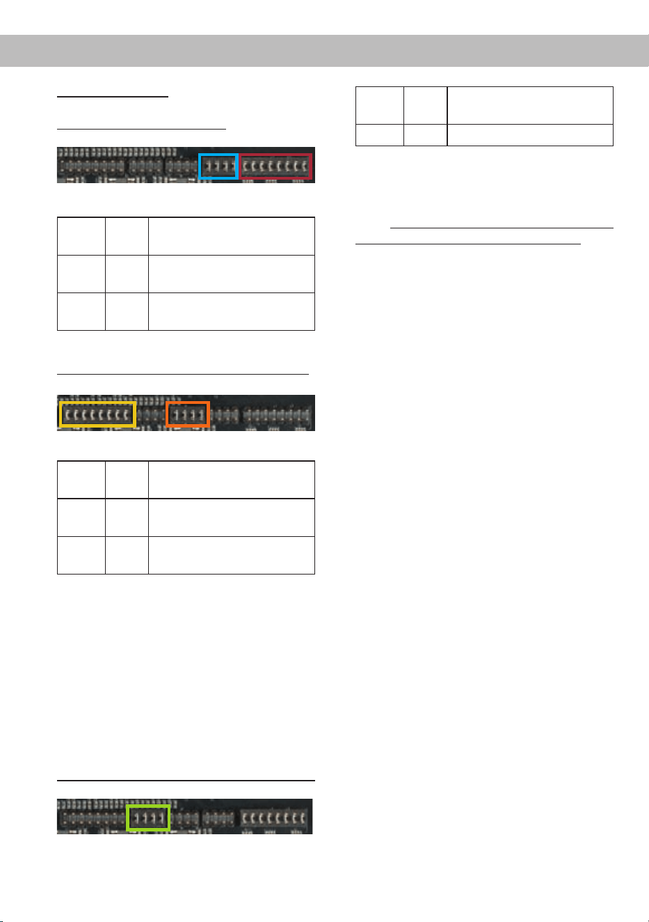
Sie haben nun Zugriff auf zwei Steckbrücken.
Die lange Steckbrücke (Jumper A, 16-polig) be-
einusst die Kanäle A - D, die kurze (Jumper B,
8-polig) die Kanäle E und F. Für Jumper A gibt
es zwei Steckpositionen (A1 und A2), für Jum-
per B drei (B1, B2 und B3). Im Folgenden wer-
den die verschiedenen Steckpositionen be-
schrieben:
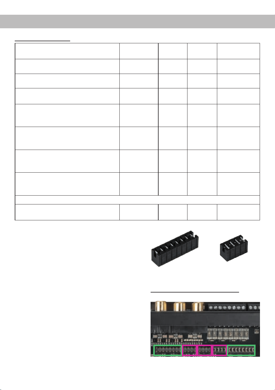
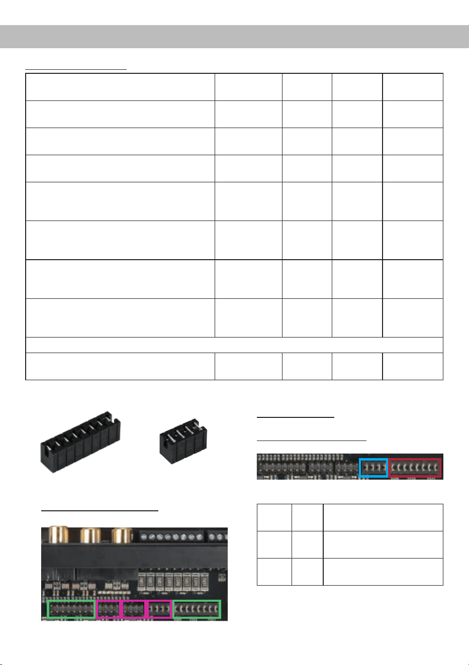
Überischt Jumper-Steckpositionen:
Jumper A Jumper B
A1B1A2 B3 B2
Einstellungsbeispiele:
Quelle Welcher
Eingang
Position
Jumper A
Position
Jumper B
Position Potis
OEM-Radio 4-kanalig
Bis 25 Watt Sinusleistung pro Kanal
Highlevel A-D A1 Beliebig Linksanschlag
OEM-Radio mit Zusatzverstärker 4-kanalig
Bis 100 Watt Sinusleistung pro Kanal
Highlevel A-D A2 Beliebig Linksanschlag
OEM-Radio mit Zusatzverstärker 6-kanalig
Bis 100 Watt Sinusleistung pro Kanal
Highlevel A-F A2 B2 Linksanschlag
Handelsradio 4-kanalig ohne
Vorverstärkerausgang
Bis 25 Watt Sinusleistung pro Kanal
Highlevel A-D A1 Beliebig Linksanschlag
Handelsradio 4-kanalig mit
Vorverstärkerausgang
2 Volt Vorverstärkerausgangsspannung
Lowlevel /
Cinch A-D
A1 Beliebig Rechtsanschlag
Handelsradio 4-kanalig mit
Vorverstärkerausgang
4 Volt Vorverstärkerausgangsspannung
Lowlevel /
Cinch A-D
A1 Beliebig Linksanschlag
Handelsradio 5/6-kanalig mit
Vorverstärkerausgang
8 Volt Vorverstärkerausgangsspannung
Lowlevel /
Cinch A-F
A2 B2 Linksanschlag
Nutzung der Eingänge E-F bei Radios mit vier Ausgangskanälen
Smartphones, Tablets, MP3-Player, mobile
Navigationsgeräte, etc.
Lowlevel /
Cinch E-F
Siehe
oben
B3 Linksanschlag
8
Jumperpositionen:
Werkseitige Jumperpositionen:
Jum-
per
Posi-
tion
Wertebereich
A 1 Highlevel A - D: 5 – 10 Volt
Cinch A - D: 2 – 4 Volt
B 1 Highlevel E - F: 5 – 10 Volt
Cinch E - F: 2 – 4 Volt
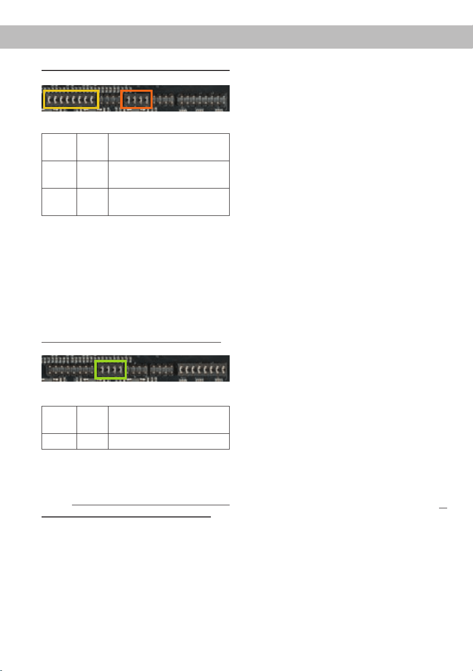
Jumperpositionen für erweiterten Stellbereich:
Jum-
per
Posi-
tion
Wertebereich
A 2 Highlevel A - D: 10 – 20 Volt
Cinch A - D: 4 – 8 Volt
B 2 Highlevel E - F: 10 – 20 Volt
Cinch E - F: 4 – 8 Volt
Der Stellbereich der Eingangsempndlichkeit
der Vorverstärkereingänge E und F lässt sich
durch Umstecken des Jumpers B so verändern,
dass auch mobile Geräte wie z.B. Smartphones
mit deutlich geringerer Ausgangsspannung
problemlos angeschlossen werden können.
Die Eingangsempndlichkeit ist von 170 mV –
340 mV regelbar, wenn Jumper B in der nach-
folgend markierten Position eingesteckt ist:
AUX Jumperposition für die Cinch Eingänge E - F:
Jum-
per
Posi-
tion
Wertebereich
B 3
Cinch E – F: 170 mV – 340 mV
Hinweis: Um die Position eines Jumpers zu
ändern, ziehen Sie diesen einfach nach oben
hin ab und stecken ihn auf die gewünschte Po-
sition. Achten Sie darauf, dass der Jumper voll-
ständig und nicht versetzt eingesteckt ist.
Beide Jumper können unabhängig voneinander
umgesteckt werden.
Um die Eingangsempndlichkeit mit Hilfe der
Drehpotentiometer optimal an ihre Signalquel-
le anzupassen, führen Sie bitte die folgenden
Schritte durch:
1. Schließen Sie während dieser Prozedur
keine Lautsprecher an die Ausgänge des
Verstärkers an und schalten Sie ggfs. an-
geschlossene Verstärker ab.
2. Drehen Sie die Lautstärke Ihres Radios auf
90 % der Gesamtlautstärke und spielen Sie
über das CD-Laufwerk ein 1 kHz Testsignal
(Vollaussteuerung 0 dB) ab.
3. Die Einstellung geht leichter vonstatten,
wenn Sie die Eingangskanäle nacheinan-
der anschließen und einstellen.
4. Sollte die Clipping LED bereits leuchten,
verringern Sie mit Hilfe des entsprechenden
Drehpotentiometers (Punkt 6 Seite 3; Input
Sensitivity) die Eingangsempndlichkeit
des jeweiligen Kanalpaares, bis die Clip-
ping LED erlischt. Sollte das Potentiometer
bereits auf Linksanschlag stehen, muss der
Wertebereich der Eingangsempndlichkeit
über die internen Jumper verändert werden.
5. Erhöhen Sie die Eingangsempndlichkeit
durch Rechtsdrehung des jeweiligen Poten-
tiometers bis die Clipping LED aueuchtet.
Drehen Sie nun das Potentiometer gegen
den Uhrzeigersinn, bis die Clipping LED
wieder erlischt.
6. Wiederholen Sie diesen Vorgang für jedes
genutzte Signaleingangspaar.
4. Anschluss einer digitalen Signalquelle
Sofern Sie über eine Signalquelle mit optischem
Digitalausgang verfügen, kann diese an den
A1B1
A2 B2
B3
Einbau und Installation

9
Verstärker angeschlossen werden. Die HELIX
P SIX DSP MK2 ist werkseitig so konguriert,
dass automatisch auf den Digitaleingang umge-
schaltet wird, wenn dort ein Audiosignal anliegt.
Diese Funktion kann über die DSP PC-Tool
Software deaktiviert bzw. auf einen manuellen
Modus (in Verbindung mit einer optional erhält-
lichen Fernbedienung) geändert werden. Die
Einschaltautomatik des Verstärkers funktioniert
bei Verwendung des Digitaleingangs nicht, so
dass der Remote-Eingang (REM) zwingend be-
legt werden muss.
Eine gleichzeitige Nutzung des Digitaleingangs
sowie der Highlevel- oder der Vorverstärkersi-
gnaleingänge ist möglich.
Wichtig: Das digitale Audiosignal einer Quelle
ist üblicherweise nicht lautstärkegeregelt. Das
bedeutet, dass an sämtlichen Ausgängen der
HELIX P SIX DSP MK2 der volle Pegel anliegt.
Dies kann im Extremfall die angeschlossenen
Lautsprecher zerstören. Wir raten deshalb
dringend dazu, eine optionale Fernbedienung
zur Einstellung der Lautstärke der digitalen
Signaleingänge zu verwenden!
Hinweis: Die HELIX P SIX DSP MK2 kann nur
unkomprimierte, digitale Stereo PCM-Signale
mit einer Abtastrate zwischen 12 kHz und
96 kHz verarbeiten. Es können keine Dolby-co-
dierte Signale oder komprimierte MP3-/WMA-
oder AAC Datenformate verarbeitet werden.
5. Anschluss der Stromversorgung
Vor dem Anschluss des +12 V / +24 V
Versorgungskabels an das Bordnetz muss
die Autobatterie abgeklemmt werden.
Das +12 V / +24 V Stromkabel ist am Pluspol
der Batterie anzuschließen. Die Plusleitung
sollte in einem Abstand von max. 30 cm von der
Batterie mit einer Hauptsicherung abgesichert
werden. Der Wert der Sicherung errechnet
sich aus der maximalen Stromaufnahme der
gesamten Car-Hi Anlage (P SIX DSP MK2 =
max. 60 A RMS bei 12 V Bordnetz, max. 30 A
RMS bei 24 V Bordnetz).
Verwenden Sie bei kurzen Leitungen (< 1 m)
einen Querschnitt von mindestens 16 mm². Bei
längeren Leitungen empfehlen wir einen Quer-
schnitt von 25 mm² bis 35 mm².
Das Massekabel (gleicher Querschnitt wie das
+12 V / +24 V Kabel) muss an einem blanken,
von Lackresten befreiten Massepunkt des
Kfz-Chassis oder direkt an dem Minuspol der
Autobatterie angeschlossen werden.
6. Anschluss des Remote-Eingangs
Der Remote-Eingang (REM) muss mit dem
Remote-Ausgang des Radios verbunden
sein, sofern die Vorverstärkereingänge des
Verstärkers als Signaleingänge genutzt wer-
den. Es wird dringend davon abgeraten, den
Remote-Eingang des Verstärkers über das
Zündungsplus des Fahrzeugs zu steuern, um
Störgeräusche beim Ein- und Ausschalten zu
vermeiden. Bei Verwendung des Highlevel-
Eingangs ( Highlevel Input) muss der Remote-
Eingang nicht belegt werden, sofern das ange-
schlossene Radio über BTL-Ausgangsstufen
verfügt.
7. Konguration des Remote-Eingangs
Die Einschaltung der HELIX P SIX DSP MK2
erfolgt automatisch bei Ansteuerung über die
Hochpegel-Lautsprechereingänge (High level
Input) oder sobald ein Remote-Signal am
Remote-Eingang (REM) anliegt. Mit Hilfe des
„Automatic Remote“ Schalters kann die au-
tomatische Einschaltung deaktiviert werden.
Dies sollte vorgenommen werden, wenn es bei-
spielsweise zu Störgeräuschen beim Ein- und
Ausschalten des Verstärkers kommt.
Hinweis: Wird die automatische Einschaltung
des Verstärkers deaktiviert, muss der Remote-
Eingang belegt werden. Eine automatische Ein-
schaltung über den Hochpegel-Lautsprecher-
eingang ist dann nicht mehr möglich.
Hinweis: Werkseitig ist die automatische Ein-
schaltung über den Hochpegel-Lautsprecher-
eingang der P SIX DSP MK2 aktiviert.
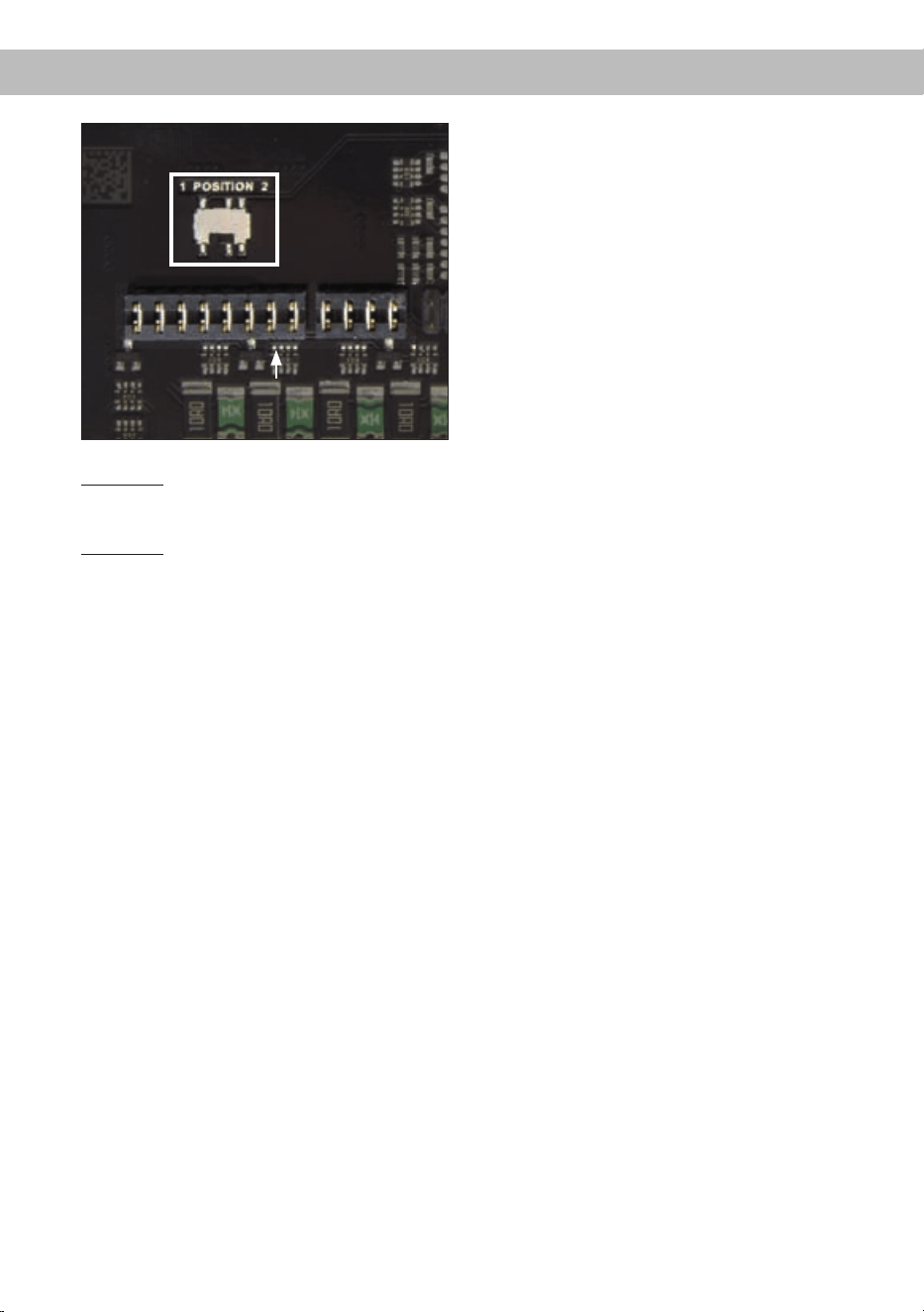
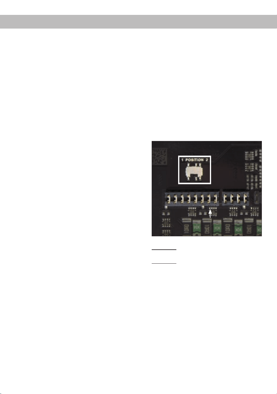
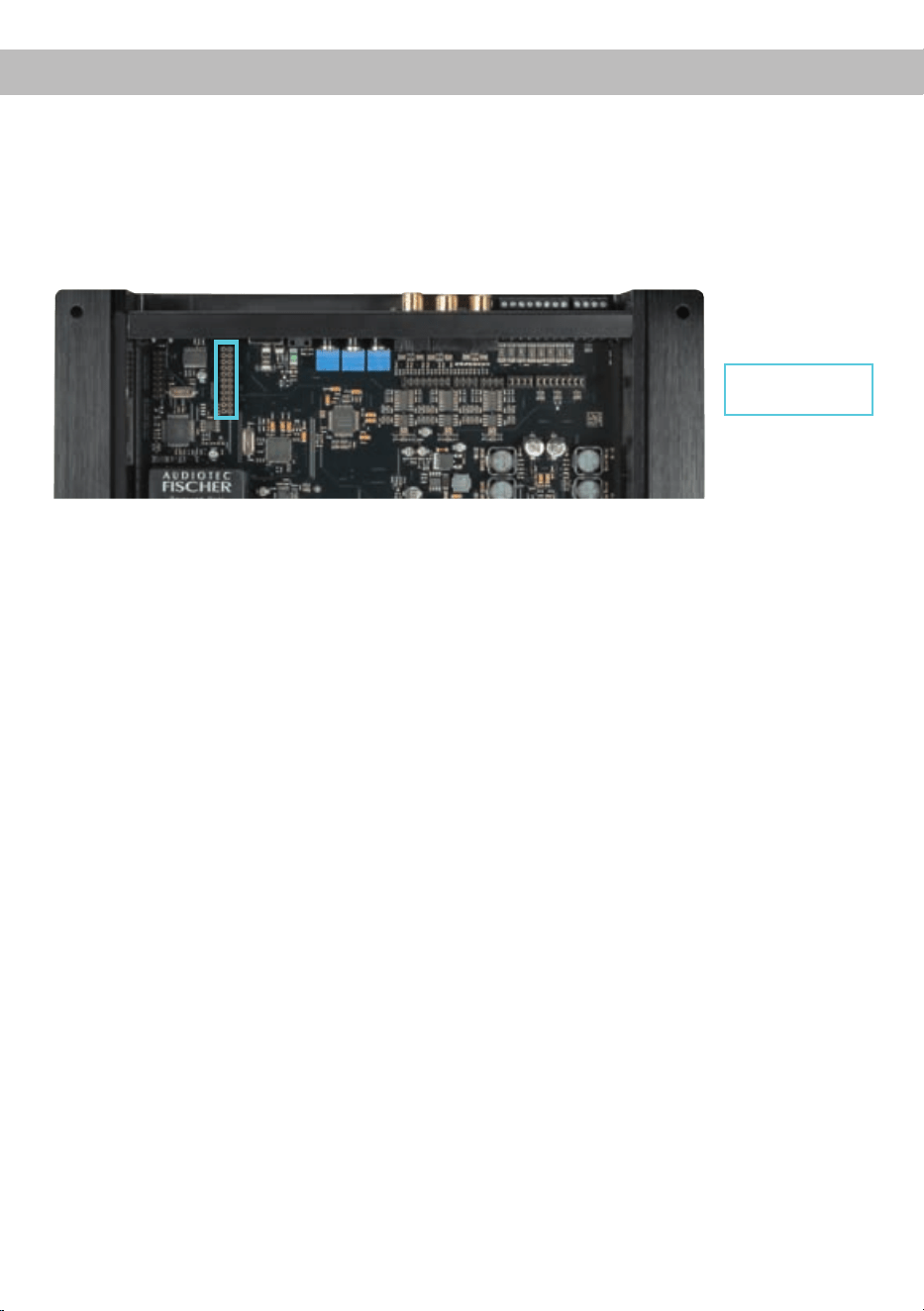
Um die automatische Einschaltung zu deakti-
vieren, muss das Gerät geöffnet und die Schal-
terposition des „Automatic Remote“ Schalters
geändert werden.
Dazu entfernen Sie bitte das Bodenblech indem
Sie die zehn Kreuzschlitzschrauben lösen und
erhalten so Zugriff auf den Schalter. Dieser be-
ndet sich in der Nähe der Steckbrückenplätze
(Jumperpositionen) A1 und B1 (siehe Markie-
rung im nachfolgenden Bild).
10
Jumper A1 & B1
Position 1: Einschaltung über Hochpegel-
Lautsprechereingang aktiviert
(Werkseinstellung).
Position 2: Einschaltung über Hochpegel-Laut-
sprechereingang deaktiviert.
8. Konguration des internen DSPs
Es wird dringend empfohlen vor der er-
sten Inbetriebnahme die grundlegenden
Einstellungen im Verstärker mit Hilfe der
DSP PC-Tool Software vorzunehmen.
Eine Missachtung kann zur Zerstörung der
angeschlossenen Lautsprecher / Verstär-
ker führen. Speziell bei Verwendung der
P SIX DSP MK2 in vollaktiven Systemen be-
steht sonst Zerstörungsgefahr für die Hochtö-
ner. Informationen zum Anschluss des Verstär-
kers an einen PC nden Sie auf Seite 12.
9. Anschluss der Lautsprecherausgänge
Die Lautsprecherausgänge können direkt mit
den Lautsprecherleitungen verbunden wer-
den. Verbinden Sie niemals die Lautsprecher-
leitungen mit der Kfz-Masse (Fahrzeugkaros-
serie). Dieses kann Ihren Verstärker und Ihre
Lautsprecher zerstören.
Achten Sie darauf, dass alle Lautsprechersy-
steme phasenrichtig angeschlossen sind, d.h.
Plus zu Plus und Minus zu Minus. Vertauschen
von Plus und Minus hat einen Totalverlust der
Basswiedergabe zur Folge. Der Pluspol ist bei
den meisten Lautsprechern gekennzeichnet.
Die Impedanz darf bei den Kanälen A und B
4 Ohm nicht unterschreiten, alle übrigen Ka-
näle können mit minimal 2 Ohm belastet wer-
den. Die Kanäle sind nicht brückbar und dürfen
somit nicht im Brückenbetrieb genutzt werden.
Für Subwooferkongurationen benutzen Sie
bitte Doppelschwingspulensubwoofer.
10. Anschluss des Remote-Ausgangs
Dieser Ausgang (Rem Out) dient dazu einen
angeschlossenen Zusatzverstärker mit einem
Remote-Signal zu versorgen. Bitte verwenden
Sie ausschließlich dieses Signal zur Einschal-
tung des externen Verstärkers, um Ein- und
Ausschaltgeräusche zu vermeiden.
Einbau und Installation
11
Um die Installation der P SIX DSP MK2 an ein
Werks- oder Nachrüstradio deutlich zu vereinfa-
chen, kann der Verstärker auch mit Hilfe des op-
tional erhältlichen Easy Plug Kabels (EPC 5) an-
geschlossen werden. Über dieses Kabel wird die
P SIX DSP MK2 mit den Lautsprechersignalen des
Radios versorgt. Zudem muss bei dieser Installati-
on kein Kabel des Werkssoundsystems durchtrennt
werden. Das Easy Plug Kabel nutzt die Hochpegel-
Lautsprechereingänge A - D.
Hinweis: Die Versorgungsspannungsleitungen
des Easy Plug Kabels dürfen unter keinen Um-
ständen zur Spannungsversorgung des Verstär-
kers verwendet werden!
Im Folgenden wird der Anschluss an das Werksra-
dio beschrieben:
1. Nachdem das Radio mit Hilfe der entspre-
chenden Werkzeuge ausgebaut ist, trennen Sie
den Fahrzeugkabelbaum vom Autoradio. Ver-
binden Sie den Fahrzeugkabelbaum anschlie-
ßend mit der Kupplung des Easy Plug Kabels.
Je nach Fahrzeugtyp benötigen Sie hierfür
gegebenenfalls einen fahrzeugspezischen
ISO-Adapter. Eine Liste aller Fahrzeuge und
der eventuell benötigten Adapter nden Sie auf
www.audiotec-scher.com.
2. Verbinden Sie die Stecker des Easy Plug Ka-
bels mit dem Autoradio.
3. Verbinden Sie den Highlevel-Stecker (8-poliger
Stecker) mit den jeweiligen Eingängen des Ver-
stärkers. Der Stromversorgungsstecker (4-po-
liger Stecker) bleibt ungenutzt!
Hinweis: MOST-Bus
Bei einigen Fahrzeugen kann es notwendig sein,
die Lichtleiterverbindung aus dem Original-Radio-
anschlussstecker auszulösen und stattdessen in
den Radio-Stecker eines ISO-Adapters einzuste-
cken. Hierfür ist extra eine Aussparung im ISO-
Adapter vorhanden. Dies ist zwingend bei allen
Fahrzeugen notwendig, die einen Lichtleiteran-
schluss im Originalradiokabelbaum haben.
Anschluss mit Hilfe des „Easy Plug Cables“
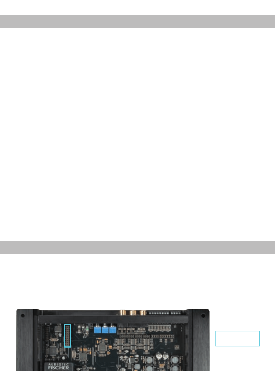
Die HELIX P SIX DSP MK2 kann durch die Monta-
ge einer HELIX Extension Card (HEC) um weitere
Funktionen erweitert werden - beispielsweise um
eine Bluetooth
®
Audiostreaming Funktion, einem
weiteren optischen Digitaleingang oder einem op-
tischen Digitalausgang.
Zur Montage einer HEC muss das Seitenblech der
P SIX DSP MK2 demontiert und gegen das der HEC
beiliegende Seitenblech ausgetauscht werden. De-
taillierte Informationen zum Einbau nden Sie in der
Bedienungsanleitung der jeweiligen HELIX Exten-
sion Card.
HELIX Extension
Card Slot
HELIX Extension Card Slot (HEC Slot)
12
Anschluss an den Computer
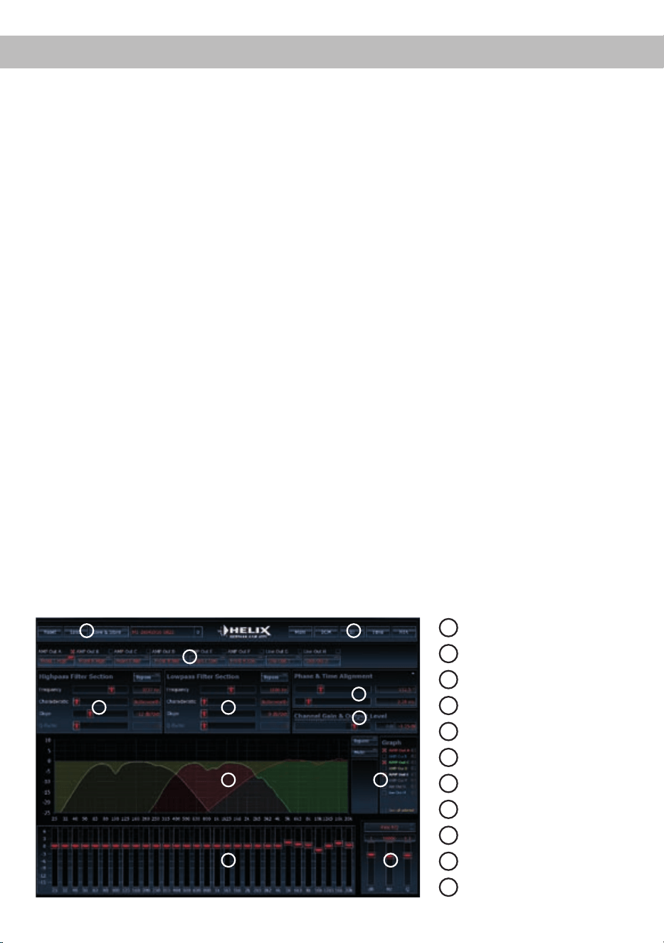
1
Laden und Speichern
2
Hauptmenü
3
Kanalkonfiguration
4
Hochpassfilter
5
Tiefpassfilter
6
Laufzeitkorrektur
7
Ausgangspegel
8
Frequenzgraph
9
Auswahl Frequenzgraphen
10
Equalizer
11
EQ Feineinstellung
Die HELIX P SIX DSP MK2 kann mit Hilfe der
DSP PC-Tool Software frei konguriert werden. Die
Software stellt alle Funktionen übersichtlich und
bedienerfreundlich zur Verfügung, so dass Sie die-
se individuell einstellen können. Dabei können alle
acht DSP Kanäle separat eingestellt werden.
Bevor Sie die HELIX P SIX DSP MK2 das erste
Mal an einen Computer anschließen, gehen Sie
auf unsere Homepage und laden die aktuellste
Software Version des DSP PC-Tools herunter. Es
ist ratsam, regelmäßig nach Updates der Software
zu schauen, damit das Gerät immer auf dem aktu-
ellsten Stand ist.
Die Software sowie die dazugehörige Bedienungsan-
leitung nden Sie auf www.audiotec-scher.com.
Es wird dringend empfohlen die Bedienungsanlei-
tung der Software (Sound Tuning Magazin) vor der
ersten Benutzung durchzulesen, um Komplikati-
onen und Fehler zu vermeiden.
Wichtig: Stellen Sie sicher, dass die
HELIX P SIX DSP MK2 bei der ersten Installation
der Software noch nicht an den PC angeschlossen
ist. Verbinden Sie diesen erst, wenn die Software
vollständig installiert ist!
Im folgenden Abschnitt lesen Sie die wichtigsten
Schritte zum Anschluss und der ersten Inbetrieb-
nahme:
1. Laden Sie die DSP PC-Tool Software unter
www.audiotec-scher.com herunter und instal-
lieren diese auf ihrem Computer.
2. Schließen Sie danach den Verstärker mit dem
beiliegenden USB-Kabel an den Computer an.
Wenn Sie längere Distanzen zu überbrücken
haben, verwenden Sie bitte eine aktive USB-
Verlängerung mit integriertem Repeater und
kein passives USB-Kabel.
3. Schalten Sie erst den Verstärker ein und star-
ten Sie anschließend die Software. Sofern die
Betriebssoftware des Verstärkers nicht mehr
aktuell ist, wird diese automatisch aktualisiert.
4. Nun können Sie die P SIX DSP MK2 mithilfe
der DSP PC-Tool Software frei kongurieren.
Nützliche Hinweise zur korrekten Einstellung
entnehmen Sie z.B. unserem „Sound Tuning
Magazin“, welches auf unserer Webseite zum
Download bereit steht.
Achtung: Es wird dringend empfohlen, vor der
ersten Inbetriebnahme die Lautstärke am Radio
auf Minimum zu drehen und an die Lautsprecher-
ausgänge sowie den Line Output des Verstärkers
noch nichts anzuschließen, bis die grundlegenden
Einstellungen im Verstärker vorgenommen wurden.
Speziell bei Verwendung der P SIX DSP MK2 in
vollaktiven Systemen besteht sonst Zerstörungsge-
fahr für die Hochtöner.
8
1
6
3
4
7
5
2
9
10 11

13
Ultra HD Class D Verstärker-Technologie mit
96 kHz Abtastrate
Die P SIX DSP MK2 ist der erste Class D-Verstär-
ker mit integriertem Signalprozessor, der mit der
doppelten Abtastrate von 96 kHz arbeitet. Dadurch
ist die Audiobandbreite nicht wie üblich auf 22 kHz
begrenzt, sondern erlaubt einen ausgedehnten
Frequenzgang bis über 40 kHz. Die höhere Abta-
strate stellt jedoch deutlich höhere Anforderungen
an sämtliche Komponenten im Gerät. Erst der Ein-
satz der allerneuesten Chipgeneration sowohl beim
DSP als auch bei den Endstufen macht dies mög-
lich. Das Resultat: eine Klagqualität wie sie bislang
von Class D-Endstufen nicht bekannt war.
Ready for 24 V
Die P SIX DSP MK2 ist nicht nur für den Einsatz
an 12 V-Bordnetzen geeignet, sondern kann ohne
jegliche Änderungen oder Einstellungen am Ge-
rät auch an 24 Volt-Bordnetzen, wie sie z.B. im
LKW-Bereich üblich sind, betrieben werden. Die
Leistungsdaten der P SIX DSP MK2 sind für beide
Betriebsmodi identisch. Somit ist maximale Flexibi-
lität für alle erdenklichen Einsatzzwecke gegeben.
Power Save Modus
Der Power Save Modus ist in den Grundein-
stellungen der DSP PC-Tool Software akti-
viert. Er erlaubt es, die Leistungsaufnahme der
P SIX DSP MK2 (und ggf. zusätzlich angeschlos-
sener Verstärker) drastisch zu reduzieren, wenn
für länger als 60 Sek. kein Eingangssignal anliegt.
Sobald der „Power Save Mode“ aktiv ist, werden
die internen Verstärkerstufen der P SIX DSP MK2
sowie der Rem Out abgeschaltet und damit die
Stromaufnahme deutlich reduziert. Der Verstärker
geht innerhalb von 2 Sek. wieder in den normalen
Betriebszustand über, sobald ein Musiksignal an
seinem Eingang anliegt. Über die DSP PC-Tool
Software kann die Abschaltverzögerung variiert
bzw. komplett deaktiviert werden.
Start-Stopfähigkeit
Das Netzteil im HELIX P SIX DSP MK2 Verstärker
stellt die interne Spannungsversorgung auch bei
kurzfristigen Einbrüchen bis hinab zu 6 Volt sicher.
Damit ist gewährleistet, dass die HELIX
P SIX DSP MK2 auch beim Motorstart voll funkti-
onsfähig bleibt.
Automatic Digital Signal Detection
Die Umschaltung zwischen den analogen und dem
Digitaleingang erfolgt signalgesteuert. Sobald ein
Audiosignal am Optical Input detektiert wird schal-
tet der Verstärker auf diesen Eingang um. In der
DSP PC-Tool Software kann diese Funktion deakti-
viert oder alternativ eine manuelle Steuerung über
eine optional erhältliche Fernbedienung gewählt
werden.
Intelligenter Highlevel-Eingang
Moderne, ab Werk verbaute Autoradios werden
bezüglich der Diagnose der angeschlossenen
Lautsprecher immer intelligenter. Wird ein Ver-
stärker stattdessen an das Radio angeschlossen,
kommt es meist zu Fehlermeldungen bis hin zum
Wegfall einzelner Funktionen (wie z.B. Fader). Der
neue ADEP-Schaltkreis (Advanced Diagnostics Er-
ror Protection) verhindert all diese Probleme ohne
die Lautsprecherausgänge des Radios bei hohen
Pegeln unnötig zu belasten.
Spezielle Features der HELIX P SIX DSP MK2

14
Leistung RMS
- Kanäle A - F @ 4 Ohm ..................................................120 Watt pro Kanal (≤ 1% THD+N)
- Kanäle C - F @ 2 Ohm……………………………………230 Watt pro Kanal (≤ 1% THD+N)
Eingänge .........................................................................6 x Cinch
6 x Hochpegel-Lautsprechereingang
1 x Optisch SPDIF (12 - 96 kHz)
1 x Remote In
Eingangsempndlichkeit .................................................. Cinch 2 - 4 Volt oder 4 - 8 Volt
Hochpegel 5 - 10 Volt oder 10 - 20 Volt
Ausgänge ........................................................................6 x Lautsprecher
2 x Cinch
2 x Remote Out
Ausgangsspannung Cinch...............................................3 Volt RMS
Frequenzbereich..............................................................20 Hz - 44.000 Hz
DSP Auösung ................................................................64 Bit
DSP Rechenleistung .......................................................295 MHz (1,2 Mrd. MAC Operationen/Sekunde)
Abtastrate ........................................................................96 kHz
Signalwandler ..................................................................A/D: BurrBrown
D/A: BurrBrown
Signal-/ Rauschabstand Digitaleingang...........................105 dB (A-bewertet)
Signal-/ Rauschabstand Analogeingang..........................100 dB (A-bewertet)
Klirrfaktor (THD) ..............................................................< 0,008 %
Dämpfungsfaktor .............................................................> 100
Eingangsimpedanz Cinch ................................................ 64 kOhm
Eingangsimpedanz Highlevel ..........................................13 Ohm oder 64 kOhm
Betriebsspannung............................................................10,5 - 32 Volt (max. 5 Sek. bis hinab zu 6 Volt)
Zusätzliche Features .......................................................Control Input, USB, HEC Slot, Automatic Remote
Schalter
Abmessungen (H x B x T) ...............................................50 x 260 x 190 mm
Technische Daten
Die Garantieleistung entspricht der gesetzlichen Re-
gelung. Von der Garantieleistung ausgeschlossen
sind Defekte und Schäden, die durch Überlastung
oder unsachgemäße Behandlung entstanden sind.
Eine Rücksendung kann nur nach vorheriger Abspra-
che in der Originalverpackung, einer detaillierten
Fehlerbeschreibung und einem gültigen Kaufbeleg
erfolgen. Technische Änderungen und Irrtümer vor-
behalten! Für Schäden am Fahrzeug oder Geräte-
defekte, hervorgerufen durch Bedienungsfehler des
Gerätes, können wir keine Haftung übernehmen.
Dieses HELIX-Produkt ist sowohl mit einer E-Kenn-
zeichnung als auch mit einer CE-Kennzeichnung
ausgestattet und damit für den Betrieb in Fahrzeu-
gen innerhalb der Europäischen Union (EU) zerti-
ziert.
Garantiehinweis
Hinweis:
„Die Bluetooth
®
Wortmarke und die Logos sind eingetragene Warenzeichen der Bluetooth SIG, Inc. und jegliche Nutzung dieser Marken durch
die Audiotec Fischer GmbH geschieht unter Lizenz. Andere Handelsmarken und Handelsnamen gehören den jeweiligen Inhabern.“

15
Dear Customer,
Congratulations on your purchase of this innovative
and high-qual ity HELIX product.
With the HELIX P SIX DSP MK2, Audiotec Fischer
is setting new standards in the range of digital
ampliers.
We wish you many hours of enjoyment with your
new HELIX P SIX DSP MK2.
Yours,
AUDIOTEC FISCHER
General installation instructions for HELIX
components
To prevent damage to the unit and possible injury,
read this manual carefully and follow all installation
instructions. This product has been checked for
proper function prior to shipping and is guaranteed
against manufacturing defects.
Before starting your installation, disconnect
the battery’s negative terminal to prevent
damage to the unit, re and / or risk of injury. For
a proper performance and to ensure full warranty
coverage, we strongly recommend to get this prod-
uct installed by an authorized HELIX dealer.
Install your HELIX P SIX DSP MK2 in a dry loca-
tion with sufcient air circulation for proper cooling
of the equipment. The amplier should be secured
to a solid mounting surface using proper mount-
ing hardware. Before mounting, carefully examine
the area around and behind the proposed instal-
lation location to insure that there are no electrical
cables or components, hydraulic brake lines or any
part of the fuel tank located behind the mounting
surface. Failure to do so may result in unpredictable
damage to these components and possible costly
repairs to the vehicle.
General instruction for connecting the HELIX
P SIX DSP MK2 amplier
The HELIX P SIX DSP MK2 amplier may only be
installed in vehicles which have a 12 Volts / 24 Volts
negative terminal connected to the chassis ground.
Any other system could cause damage to the am-
plier and the electrical system of the vehicle. The
positive cable from the battery for the complete
system should be provided with a main fuse at a
distance of max. 30 cm from the battery. The val-
ue of the fuse is calculated from the maximum total
current input of the car audio system.
Use only suitable cables with sufcient ca-
ble cross-section for the connection of HELIX
P SIX DSP MK2. The fuses may only be replaced
by identically rated fuses (3 x 20 A) to avoid
damage of the amplier.
Prior to installation, plan the wire routing to
avoid any possible damage to the wire harness.
All cabling should be protected against possible
crushing or pinching hazards. Also avoid routing
cables close to potential noise sources such as
electric motors, high power accessories and other
vehicle harnesses.
Congratulations!
General instructions
16
Connectors and control units
1
Control pushbutton
Use this button to either switch between the
setups or initiate a reset of the device.
2
Status LED
This LED indicates the operating mode of the
DSP and which setup has been chosen.
3
USB Input
Connects the HELIX P SIX DSP MK2 to your
PC.
4
Control Input
Multifunction interface for e.g. an optional
remote control or other HELIX accessory.
5
Optical Input
Optical input for digital stereo signals (SPDIF
format).
6
Input Sensitivity
Controller for adjusting the input sensitivity of
the low- and highlevel inputs for the individual
stereo signals.
7
Line Input
RCA inputs for connecting pre-amplier
signals.
8
Highlevel Input
Highlevel speaker inputs for connecting a
factory radio or an aftermarket radio without
pre-amp / line outputs.
9
Output Channels A - D
Speaker outputs A - D for connecting speaker
systems. The channels A and B may not be
loaded with more than 4 Ohms, all other
channels are 2 Ohms stable.
10
Clipping LED
This LED lights up red if one of the analog
inputs is overdriven.
11
Fuse
This LED lights up red if a fuse is faulty in the
device.
12
GND
Connector for the ground cable (negative
terminal of the battery or metal body of the
vehicle).
13
REM
Connector for the remote cable.
14
+12 V / +24 V
Connector for the +12 V / +24 V power cable
to the positive terminal of the battery.
15
Line Output
Line outputs for connecting external ampli-
ers. Make sure that the remote output (Rem
Out) is used to turn on these devices.
16
Rem Out
The remote output has to be used to turn on/
off external ampliers that are connected to
the RCA line outputs. Both connections are
internally wired in parallel.
17
Output Channels E - F
Speaker outputs E and F for connecting
speaker systems. These channels are
2 Ohms stable.
9 10 11 12 13 14 15 16 17
1 432 5 6 7 8

17
1
Control pushbutton
The control pushbutton allows the user to switch
between the two setup memory positions. To switch
between the setups the button has to be pressed
and held for 1 second. Switching is indicated by
a single red ash of the Status LED. Pressing the
button for 5 seconds completely eras es the internal
memory. This is indicated by a constant ashing of
the Status LED.
Attention: After erasing the setups from memory
the HELIX P SIX DSP MK2 will not reproduce any
audio output.
2
Status LED
The Status LED indicates the current active DSP
setup. Green means that setup 1 is load ed, orange
means that setup 2 is loaded. A ashing red light in-
dicates that no setup is loaded. In that case please
load a new setup via the DSP PC-Tool software.
3
USB Input
Connect your personal computer to the
P SIX DSP MK2 using the provided USB cable. The
required PC software to congure this amplier can
be downloaded from the Audiotec Fischer website
www.audiotec-scher.com.
Please note: It is not possible to connect any USB
storage devices.
4
Control Input
This multi-functional input is designed for HELIX
P SIX DSP MK2 accessory products like a remote
control which allows to adjust several features of
the amplier. Depending on the type of remote con-
trol, at rst its functionality has to be dened in the
“ Device Conguration Menu” of the DSP PC-Tool
software.
5
Optical Input
Optical input in SPDIF format for connecting signal
sources with a digital audio output. The sampling
rate of this input must be between 12 and 96 kHz.
The input signal is automatically adjusted to the in-
ternal sample rate. In order to control the volume of
this input, we recommend to use an optional remote
control.
Notice: This amplier can only handle stereo input
signals and no Dolby-coded digital audio stream.
6
Input Sensitivity
These potentiometers are used to adjust the input
sensitivity of the low- and highlevel inputs for the
individual stereo signals. This is not a volume con-
trol, it´s only for adjusting the amplier gain. The
control range of the RCA / Line Input is 2 - 4 Volts
and 5 - 10 Volts for the Highlevel Input. The input
sensitivity range can be changed by repositioning
jumpers inside the device.
Attention: It is mandatory to properly adapt the in-
put sensitivity of the P SIX DSP MK2 to the signal
source in order to avoid damage to the amplier.
7
Line Input
6-channel pre-amplier input to connect signal
sourc es such as radios. Input sensitivity is
factory-set to 4 Volts (maximum CCW position). It
is possible to vary the sensitivity between 2 and
4 Volts for each channel pair. By repositioning a
jumper inside the device the sensitivity range can
be changed to 4 - 8 Volts.
8
Highlevel Input
6-channel highlevel loudspeaker input to connect
the amplier directly to loudspeaker outputs of
OEM / aftermarket radios or OEM ampliers that do
not have any pre-amplier outputs. Input sensitivity
is factory-set to 10 Volts (maximum CCW position).
It is possible to vary the sensitivity between 5 and
10 Volts for each channel pair. By repositioning a
jumper inside the device the sensitivity range can
be changed to 10 - 20 Volts.
By changing the sensitivity range the input imped-
ance of the highlevel inputs is shifted as well in or-
der to guarantee a perfect operation in combination
with OE radios and high-power OE ampliers. Input
impedance is set to 13 Ohms for a sensitivity range
of 5 - 10 Volts and 64 kOhms for a sensitivity range
of 10 - 20 Volts.
Attention: Solely use the pluggable screw-termi-
nal for the highlevel connector which is included in
delivery!
9
Output Channels A - D
These connections serve as speaker outputs
of the channels A - D. Never connect any of the
loudspeaker cables with the car chassis ground.
It damages your amplier and your speakers. En-
Initial start-up and functions

sure that the loudspeaker systems are correctly
connected (phase), i.e. plus to plus and minus to
minus. Exchanging plus and minus causes a total
loss of bass reproduction. The plus pole is indicated
on most speakers. The impedance of the speakers
of the channels A and B must not be lower than
4 Ohms. All other channels can be loaded with a
minimum of 2 Ohms. The speaker outputs are not
bridgeable.
10
Clipping LED
This LED lights up red if one of the six Line Inputs
or Highlevel Inputs is overdriven. The LED has no
function if the device is fed with digital input signals.
If this LED lights up reduce the input sensitivity by
using the potentiometers until the LED goes out.
11
Fuse
If a severe malfunction inside the amplier will blow
the internal fuses the LED lights up red. During nor-
mal operation this LED lights up green.
12
GND
The ground cable should be connected to a com-
mon ground reference point (this is located where
the negative terminal of the battery is grounded
to the metal body of the vehicle) or to a prepared
metal location on the vehicle chassis i.e. an area
which has been cleaned of all paint residues. Rec-
ommended cross section: min. 16 mm² / AWG 6.
13
REM
The remote input has to be used to turn on/off the
P SIX DSP MK2 if the signal source which is con-
nected to the highlevel inputs is not activating the
“automatic turn-on” function or if the amplier shall
only be activated/deactivated by a remote signal
applied to the remote input (REM).
The remote lead should be connected to the remote
output / automatic antenna (aerial positive) output
of the head unit/car radio. This is only activated if
the head unit is switched on. Thus the amplier is
switched on and off together with the head unit. This
input needn´t to be assigned if the Highlevel Input
is used.
To deactivate the “automatic turn-on” function read
the description on page 22, “Conguration of the
remote input”.
14
+12 V / +24 V
The amplier can be operated with +12 V or +24 V
supply voltage. Connect the power cable to the pos-
itive terminal of the battery. Recommended cross
section: min. 16 mm² / AWG 6.
15
Line Output
2-channel pre-amplier output for connecting
external ampliers. The output voltage is 3 Volts
max. The outputs can be assigned to any of the in-
puts as desired using the DSP PC-Tool software. If
you use this output it is mandatory to turn on/off the
external amplier via the Rem Out in order to avoid
any pop noise.
16
Rem Out
We strongly recommend to use this output for turn-
ing on/off additional ampliers that are connected
to the Line Outputs of the HELIX P SIX DSP MK2.
This is essential to avoid any interfering signals.
This output is activated automatically as soon as
the booting process of the DSP is completed. Ad-
ditionally this output will be turned off during the
“Power Save Mode” or a software update process.
17
Output Channels E - F
These connections serve as speaker outputs for the
channels E - F. Never connect the loudspeaker ca-
bles with the car chassis ground. It damages your
amplier and your speakers. Ensure that the loud-
speaker systems are correctly connected (phase),
i.e. plus to plus and minus to minus. Exchanging
plus and minus causes a total loss of bass repro-
duction. The plus pole is indicated on most speak-
ers. Output channels E and F can be loaded with a
minimum of 2 Ohms. The speaker outputs are not
bridgeable.
18
Initial start-up and functions

Installation
Connection of HELIX P SIX DSP MK2 to the head
unit/car radio:
Caution: Carrying out the following steps will re-
quire special tools and technical knowledge. In or-
der to avoid connection mistakes and / or damage,
ask your dealer for assistance if you have any ques-
tions and follow all instructions in this manual (see
page 13). It is recommended that this unit will be
installed by an authorized HELIX dealer.
1. Connecting the pre-amplier inputs
Use the correct cable (RCA / cinch cable) to
connect these inputs to the pre-amplier /
lowlev el / cinch outputs of your car radio. Each
input can be assigned to any output using the
DSP PC-Tool software. The automatic turn-on
circuit does not work when using the pre-ampli-
er inputs. In this case the remote input (REM)
has to be connected to activate the HELIX
P SIX DSP MK2.
Important: It is strictly forbidden to use the
Highlevel Input and pre-amplier inputs (Line
Input) at the same time. This may cause severe
damage to the pre-amplier outputs of your car
radio.
2. Connecting the highlevel speaker inputs
The highlevel loudspeaker inputs can be con-
nected directly to the loudspeaker outputs of an
OEM or aftermarket radio using appropriate ca-
bles (loudspeaker cables with 1 mm² / AWG 18
max.). It is not mandatory to use all speaker
inputs. Make sure that the polarity is correct. If
one or more connections have reversed polarity
it may affect the performance of the amplier. If
this input is used the remote input (REM) does
not need to be connected as the amplier will
automatically turn on once a loudspeaker signal
is received.
3. Adjustment of the input sensitivity
Attention: It is mandatory to properly adapt the
input sensitivity of the P SIX DSP MK2 to the
signal source in order to avoid damage to the
amplier.
If you want to change the Input Sensitivity use
the three potentiometers at rst. The settings of
the potentiometers affect both the lowlevel and
the highlevel inputs!
If the ex factory sensitivity range of the low-
level input (2 - 4 Volts) resp. highlevel input
(5 - 10 Volts) may not be sufcient it is possible
to change it internally by repositioning jumpers.
In that case you have to open the device. Re-
move the ten Phillips head screws of the bot-
tom plate to get access to the jumpers. The long
jumper (Jumper A, 16-pins) affects the channels
A - D and the short jumper (Jumper B, 8-pins)
the channels E and F. Inside the device there
are two plug positions (A1 and A2) for Jumper A
and three (B1, B2 and B3) for Jumper B.
The different plug positions are explained on
page 20:
19
Overview plug-in positions:
Jumper positions:
Ex factory jumper positions:
Jum-
per
Posi-
tion
Value range
A 1 Highlevel A - D: 5 – 10 Volts
RCA A - D: 2 – 4 Volts
B 1 Highlevel E - F: 5 – 10 Volts
RCA E - F: 2 – 4 Volts
Jumper A Jumper B
A1B1A2 B3 B2
A1B1
20
Examples for adjusting:
Source Which input? Position
Jumper A
Position
Jumper B
Potentiome-
ter position
4-channel OEM radio
Up to 25 Watts RMS power each channel
Highlevel A-D A1 Optional Max. CCW
position
OEM radio with additional 4-channel amplier
Up to 100 Watts RMS power each channel
Highlevel A-D A2 Optional Max. CCW
position
OEM radio with additional 6-channel amplier
Up to 100 Watts RMS power each channel
Highlevel A-F A2 B2 Max. CCW
position
4-channel aftermarket radio without
pre-amplier outputs
Up to 25 Watts RMS power each channel
Highlevel A-D A1 Optional Max. CCW
position
4-channel aftermarket radio with pre-amplier
outputs
2 Volts pre-amplier output voltage
Lowlevel /
RCA A-D
A1 Optional Max. CW
position
4-channel aftermarket radio with pre-amplier
outputs
4 Volts pre-amplier output voltage
Lowlevel /
RCA A-D
A1 Optional Max. CCW
position
5/6-channel aftermarket radio with pre-ampli-
er outputs
8 Volts pre-amplier output voltage
Lowlevel /
RCA A-F
A2 B2 Max. CCW
position
Using the inputs E and F as an AUX input in the case of radios with four output channels
Smartphones, Tablets, MP3-Player, mobile
navigation systems, etc.
Lowlevel /
RCA E-F
See
above
B3 Max.CCW
position
Installation
21
Jumper positions for extended adjustment range:
Jum-
per
Posi-
tion
Value range
A 2 Highlevel A - D: 10 – 20 Volt
RCA A - D: 4 – 8 Volt
B 2 Highlevel E - F: 10 – 20 Volt
RCA E - F: 4 – 8 Volt
The sensitivity range of the pre-amplier inputs
E and F can also be changed to connect even
mobile devices with signicantly lower output
voltage (like smartphones) by repositioning
jumper B. The input sensitivity is adjustable
from 170 mV to 340 mV if jumper B is inserted
into the marked position in the picture below.
AUX jumper position for RCA inputs E and F:
Jum-
per
Posi-
tion
Value range
B 3
RCA E – F: 170 mV – 340 mV
Important: To change the position of a jumper
it has to be removed by pulling it straight up-
wards. Make sure that the jumper is reinsert-
ed properly and all pins are fully inserted. The
position of each jumper can be changed inde-
pendently.
Follow the subsequent steps if you like to per-
fectly adapt the ampliers input sensitivity to
your audio source by using the potentiometers:
1. Don‘t connect any ampliers or loud-
speakers to the outputs of the HELIX
P SIX DSP MK2 during this setup.
2. Adjust the volume of your radio to approx.
90 % of the max. volume and playback a
1 kHz full scale test tone (0 dB) via CD
drive.
3. The adjustment will be easier when you
connect and adjust one input channel after
each other.
4. If the Clipping LED already lights up, you
have to reduce the input sensitivity via
the respective potentiometer until the LED
turns off.
If the potentiometer is already set to maxi-
mum CCW position then it will be necessary
to change the sensitivity range by reposi-
tioning the internal jumper.
5. Increase the input sensitivity by turning the
respective potentiometer clockwise until the
LED lights up. Now turn the potentiometer
counterclockwise until the Clipping LED
turns off again.
6. Repeat this process for each channel pair
you are using.
4. Connecting a digital signal source
If you have a signal source with an optical digital
output you can connect it to the amplier using
the appropriate input.
In standard conguration the HELIX
P SIX DSP MK2 automatically activates the
digital input if a digital audio signal is detect-
ed. This function can be deactivated via the
DSP PC-Tool software. Alternatively you can
manually activate the digital input if you are us-
ing the optional remote control. The automatic
turn-on circuit does not work when the digital in-
put is used. Therefore it is mandatory to connect
the remote input (REM).
Please note that it is possible to connect a
source to the digital input and the highlevel or
the pre-amplier at the same time.
Important: The signal of a digital audio source
normally does not contain any information
about the volume level. Keep in mind that this
will lead to full level on the outputs of the HELIX
P SIX DSP MK2 and your connected ampliers.
This may cause severe damage to your speak-
ers. We strongly recommend to use an optional
remote control for adjusting the volume level of
the digital signal input!
Information: The HELIX P SIX DSP MK2 can
A2 B2
B3
only handle uncompressed digital stereo sig-
nals in PCM format with a sample rate between
12 kHz and 96 kHz. Neither Dolby-coded sig-
nals nor compressed MP3-/WMA- or AAC-audio
formats will be accepted.
5. Connection to power supply
Make sure to disconnect the battery before
installing the HELIX P SIX DSP MK2!
Connect the +12 V / 24 V power cable to the
positive terminal of the battery. The positive wire
from the battery to the amplier power terminals
needs to have an inline fuse at a distance of
no more than 12 inches (30 cm) from the bat-
tery. The value of the fuse is calculated from the
maximum total current input of the whole car au-
dio system (P SIX DSP MK2 = max. 60 A RMS
at 12 V RMS, max. 30 A RMS at 24 V power
supply). If your power wires are short (less than
1 m / 40”) then a wire gauge of 16 mm² / AWG
6 will be sufcient. In all other cases we strong-
ly recommend gauges of 25 - 35 mm² / AWG
4 – 2! The ground cable (same gauge as the
+12 V / +24 V wire) should be connected to a
common ground reference point (this is locat-
ed where the negative terminal of the battery is
grounded to the metal body of the vehicle), or to
a prepared metal location on the vehicle chas-
sis, i.e. an area which has been cleaned of all
paint residues.
6. Connecting the remote input
The remote input (REM) has to be connected to
the radio remote output if the ampliers pre-am-
plier inputs are used as signal inputs. We do
not recommend controlling the remote input via
the ignition switch to avoid pop noise during turn
on/off. If the Highlevel Inputs are used this input
does not need to be connected as long as the
car radio has BTL output stages.
7. Conguration of the remote input
The HELIX P SIX DSP MK2 will be turned on
automatically if the highlevel inputs (High level
Input) are used or if a signal is applied to the
remote input (REM). The “Automatic Remote”
switch allows to deactivate the automatic turn-
on feature. The feature should be deactivated if
there are e.g. disturbing noises while switching
on/off the amplier.
Note: If the automatic turn-on function is deac-
tivated it is mandatory to use the REM terminal
to power up the amplier! The highlevel signal
will be ignored in this case.
Note: The activation of the amplier via high-
level loudspeaker input is activated ex works.
To deactivate the automatic turn-on feature you
have to open the device and change the posi-
tion of the “Automatic Remote” switch.
Therefore untighten the ten Phillips screws of
the bottom plate. Now you can remove it and
get access to the switch. The switch is located
near by the jumper positions A1 and B1 (see
marking in the following picture).
Jumper A1 & B1
Position 1: Activation via highlevel loudspeak-
er input is enabled (ex works).
Position 2: Activation via highlevel loudspeak-
er input is disabled.
8. Conguration of the integrated DSP
The general amplier settings should be
conducted with the DSP PC-Tool software
before using the amplier for the rst time.
Ignoring this advice may result in damaging the
connected speakers / ampliers. Especially if
the P SIX DSP MK2 will be used to drive ful-
ly active speaker systems, a wrong setup can
destroy your tweeters right away. Information
about connecting the P SIX DSP MK2 to a com-
puter can be found on page 25.
9. Connecting the loudspeaker outputs
The loudspeaker outputs can be connected di-
22
Installation

Installation with “Easy Plug Cable”
To simplify installation to an OEM or aftermarket
radio the HELIX P SIX DSP MK2 can also be con-
nected using the optional Easy Plug Cable (EPC 5)
which will supply the amplier with the loudspeaker
signals of the radio. No factory wires or plugs need
to be cut by using this connection method.
The Easy Plug Cable uses the highlevel inputs
A - D.
Note: Never use the power supply cables of the
Easy Plug Cable. Always directly connect the
massive screw terminals of this amplier to
your car’s battery using appropriate wires.
Connection to an OEM radio is detailed below:
1. Once the radio has been removed by using the
right tools disconnect the OEM harness from
the radio. Connect the vehicle cable jack con-
nectors of the Easy Plug Cable. You may need
a special ISO-adaptor depending on vehicle
type. In order to verify please check the adaptor
database on the Audiotec Fischer homepage
www.audiotec-scher.com.
2. Connect the cable plugs to the car radio.
3. Connect the highlevel plug (8-pole connector)
to the appropriate HELIX P SIX DSP MK2 input.
The power supply plug (4-pole connector) re-
mains unused.
Note - Cars equipped with MOST bus:
In cars equipped with MOST bus structure it is
mandatory to unplug the ber-optic cable from the
original radio connector and insert it into the ISO
adaptor which has a dedicated recess for this.
23
rectly to the wires of the loudspeakers. Never
connect any of the loudspeaker cables with the
chassis ground as this will damage your ampli-
er and your speakers. Ensure that the loud-
speakers are correctly connected (in phase),
i.e. plus to plus and minus to minus. Exchang-
ing plus and minus causes a total loss of bass
reproduction. The plus pole is indicated on most
speakers. The impedance of the speakers of
the channels A and B must not be lower than
4 Ohms. All other channels can be loaded with
a minimum of 2 Ohms. The speaker outputs
are not bridgeable. For subwoofer applications
please use drivers with dual voice coil.
10. Connecting the remote output
This output (Rem Out) is used to supply remote
signals to the external amplier/s. Always use
this remote output signal to turn on the ampli-
ers in order to avoid on/off switching noises.
24
HELIX Extension Card slot (HEC slot)
It is possible to extend the functionality of the HELIX
P SIX DSP MK2 by inserting an optional HELIX
Extension Card (HEC) - for example a Bluetooth
®
Audio Streaming module, an additional optical digi-
tal input or an optical digital output.
To install a HELIX Extension Card it is necessary to
remove the bottom plate and one side panel of the
P SIX DSP MK2 and replace it by the new side pan-
el that comes with the HEC. Any further mounting
information will be found in the instruction manual
of the respective HELIX Extension Card.
HELIX Extension
Card slot

Connection to a PC
1
Load and save
2
Main menu
3
Channel configuration
4
Highpass filter
5
Lowpass filter
6
Time alignment
7
Output level
8
Frequency graph
9
Range of frequency graphs
10
Equalizer
11
EQ fine adjustment
8
1
6
3
4
7
5
2
9
10 11
25
It is possible to freely congure the HELIX
P SIX DSP MK2 with our DSP PC-Tool software.
The user interface is designed for easy handling of
all functions and allows an individual adjustment of
each of the eight DSP channels. Prior to connect-
ing the amplier to your PC visit our website and
download the latest version of the DSP PC-Tool
software.
Check from time to time for software updates.
You will nd the software and the respective user
manual on www.audiotec-scher.com.
We strongly recommend to carefully read the user
manual (Sound Tuning Magazine) before using the
software for the rst time in order to avoid any com-
plications and failures.
Important: Make sure that the amplier is not con-
nected to your computer before the software and
USB driver are installed!
In the following the most important steps how to
connect and the rst start-up are described:
1. Download the latest version of the
DSP PC-Tool software (available on our web-
site www.audiotec-scher.com) and install it
on you computer.
2. Connect the amplier to your computer using
the USB cable that is included in delivery. If you
have to bridge longer distances please use an
active USB extension cable with integrated re-
peater and no passive extension.
3. Turn on the amplier and start the software after
the Status LED lights up green. The operating
software will be updated automatically to the
latest version if it is not up-to-date.
4. Now you are able to congure your HELIX
P SIX DSP MK2 amplier with our intuitive
DSP PC-Tool software. Nevertheless interest-
ing and useful hints can be found e.g. in our
“Sound Tuning Magazine”, which can be down-
loaded for free from our website.
Important: We highly recommend to set the vol-
ume of you car radio to minimum position during
rst start-up. Additionally no devices or speakers
should be connected to the amplier until general
settings in the DSP PC-Tool software have been
made. Especially if the P SIX DSP MK2 will be used
to drive fully active speaker systems, a wrong setup
can destroy your tweeters right away.

26
Ultra HD Class D amplier technology with
96 kHz sampling rate
The HELIX P SIX DSP MK2 is the rst Class D am-
plier with integrated DSP on the market that runs
at 96 kHz sampling rate. Therefore the audio band-
width is no longer limited to 22 kHz, but allows an
extended frequency response to more than 40 kHz.
The higher sampling rate has only been possible
by implementing the latest DSP and amplier chip
sets.
The result: a Class D-amplier with an unprece-
dented sound quality.
Ready for 24 V
It is possible to operate the P SIX DSP MK2 with a
supply voltage of 12 Volts or 24 Volts (e.g. as usual
in trucks) without the need to make any changes
to the unit.
In both operating modes the amplier will have
equal performance characteristics. This guarantees
maximum exibility for numerous applications.
Power Save Mode
The Power Save Mode is incorporated in the ba-
sic setup. It allows to signicantly reduce the power
consumption of the P SIX DSP MK2 and connected
ampliers once there’s no input signal present for
more than 60 seconds. Please note that in many
up-to-date cars with “CAN” or any other internal
bus structures it may happen that the radio remains
“invisibly” turned on for up to 45 min. even after
leaving the car! Once the “Power Save Mode“ is
active the remote output (Rem Out) and the inter-
nal amplier stages will be turned off. The HELIX
P SIX DSP MK2 will reactivate the remote output
and the internal amplier stages within a second if a
music signal is applied. It is possible to either mod-
ify the turn-off time of 60 sec. or completely deacti-
vate the “Power Save Mode” via the DSP PC-Tool
software.
Start-Stop capability
The switched power supply of the HELIX
P SIX DSP MK2 assures a constant internal supply
voltage even if the battery’s voltage drops to 6 Volts
during engine crank.
Automatic Digital Signal Detection
Switching from analog input to the digital input is
done automatically as soon as a signal is detect-
ed on the Optical Input. This feature can be deac-
tivated in the DSP PC-Tool software. Alternatively
you can use an optional remote control for manual
switching between analog and digital inputs.
Smart highlevel input
The latest generation of OE car radios incorpo-
rates sophisticated possibilities of diagnosing the
connected speakers. If a common amplier will be
hooked up failure messages and loss of specic
features (e.g. fader function) quite often appears -
but not with the P SIX DSP MK2.
The new ADEP circuit (Advanced Diagnostics Error
Protection) avoids all these problems without load-
ing the speaker outputs of the OE radio during high
volumes unnecessarily.
Unique Features of the HELIX P SIX DSP MK2

27
RMS power
- Channel A - F @ 4 Ohms ..............................................120 Watts per channel (≤ 1% THD+N)
- Channel C - F @ 2 Ohms .............................................. 230 Watts per channel (≤ 1% THD+N)
Inputs ............................................................................... 6 x RCA / Cinch
6 Highlevel speaker input
1 x Optical SPDIF (12 - 96 kHz)
1 x Remote In
Input sensitivity ................................................................RCA / Cinch 2 - 4 Volts or 4 - 8 Volts
Highlevel 5 - 10 Volts or 10 - 20 Volts
Outputs ............................................................................6 x Speaker
2 x RCA / Cinch
2 x Remote Out
Output voltage RCA .........................................................3 Volts RMS
Frequency response ........................................................ 20 Hz - 44,000 Hz
DSP resolution .................................................................64 Bit
DSP power ......................................................................295 MHz (1.2 billion MAC operations/second)
Sampling rate ..................................................................96 kHz
Signal converters ............................................................. A/D: BurrBrown
D/A: BurrBrown
Signal-to-noise ratio digital input .....................................105 dB (A-weighted)
Signal-to-noise ratio analog input ....................................100 dB (A-weighted)
Distortion (THD) ...............................................................< 0.008 %
Damping factor ................................................................> 100
Input impedance RCA / Cinch .........................................64 kOhms
Input impedance highlevel ............................................... 13 Ohms or 64 kOhms
Operating voltage ............................................................10.5 - 32 Volts (max. 5 sec. down to 6 Volts)
Additional features ........................................................... Control Input, USB, HEC slot, Automatic Remote
switch
Dimensions (H x W x D) ..................................................50 x 260 x 190 mm / 1.97 x 10.24 x 7.48“
The limited warranty comply with legal regulations.
Failures or damages caused by overload or improp-
er use are not covered by the warranty.
Please return the defective product only with a
valid proof of purchase and a detailed malfunction
description.
Technical specications are subject to change!
Errors are reserved!
For damages on the vehicle and the device, caused
by handling errors of the device, we can’t assume
liability.
This HELIX product is tagged with an E-Certica-
tion number as well as an CE certication mark and
therefore certied for the use in vehicles within the
European community (EC).
Technical Data
Warranty Disclaimer
Note:
“The Bluetooth
®
word mark and logos are registered trademarks owned by Bluetooth SIG, Inc. and any use of such marks by
Audiotec Fischer GmbH is under license. Other trademarks and trade names are those of their respective owners.”

Audiotec Fischer GmbH
Hünegräben 26 · 57392 Schmallenberg · Germany
Tel.: +49 2972 9788 0 · Fax: +49 2972 9788 88
E-mail: helix@audiotec-scher.com · Internet: www.audiotec-scher.com