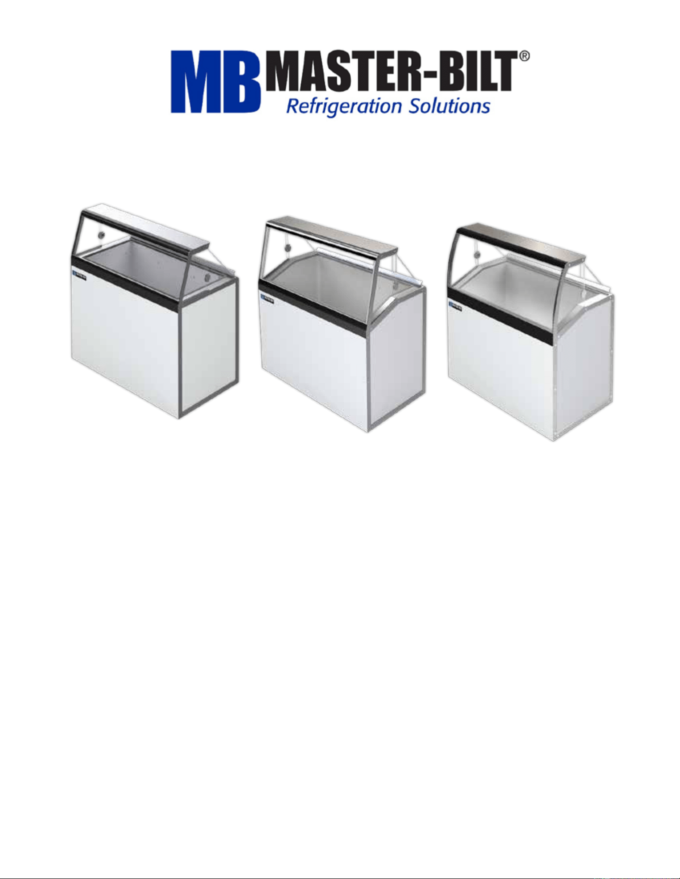
DD/DD-L/DD-LCG Series
Ice Cream Dipping-Display Cabinets
Installation & Operations Manual
Master-Bilt Products
908 Highway 15 North
New Albany, MS 38652
Phone: (800) 684-8988

57-02680- Rev. H All specifications within this publication subject to change without notice. © 2025 Master-Bilt Products, LLC. All rights reserved.
2
CONTENTS
INTRODUCTION .......................................................................................................................................... 3
STORE CONDITIONS .................................................................................................................................. 3
WARNING LABELS & SAFETY INSTRUCTIONS ....................................................................................... 4
INSPECTION FOR SHIPPING DAMAGE .................................................................................................... 5
INSTALLATION INSTRUCTIONS................................................................................................................ 6
REFRIGERANT EVACUATION & CHARGING ........................................................................................... 8
TEMPERATURE CONTROL ........................................................................................................................ 9
CLEANING INSTRUCTIONS ....................................................................................................................... 9
OPERATING CONDITIONS & PRESSURES ............................................................................................ 12
TECHNICIAN’S CONSIDERATIONS ......................................................................................................... 12
SERVICE INSTRUCTIONS ........................................................................................................................ 14
TROUBLESHOOTING GUIDE ................................................................................................................... 15
CONTROLLER SENSOR PROBE LOCATION .......................................................................................... 16
AIR FILTER CLEANING INSTRUCITONS ................................................................................................. 17
DRAINING SYSTEM .................................................................................................................................. 17
DIPPING-DISPLAY CABINET PART NUMBERS ...................................................................................... 18
OPTIONS ................................................................................................................................................... 19
DECOMMISSIONING, SALE AND DISPOSAL .......................................................................................... 19
WIRING DIAGRAMS.................................................................................................................................. 21
57-02680- Rev. H All specifications within this publication subject to change without notice. © 2025 Master-Bilt Products, LLC. All rights reserved.
3
INTRODUCTION
Thank you for purchasing a Master-Bilt dipping-display cabinet. This manual contains important instructions for installing,
using and servicing your cabinet. A parts list is also included in with this manual. Read all these documents carefully
before installing or servicing your equipment.
CAUTION
This unit uses a flammable refrigerant. Use care when handling and operating to avoid damaging the
refrigerant tubing or increasing the risk of a leak.
All service should be performed by factory authorized personnel. All component parts shall be replaced with
like components to minimize the risk of possible ignition due to incorrect parts or improper service.
This appliance is not intended for use by persons (including children) with reduced physical, sensory or
mental capabilities, or lack of experience and knowledge, unless they have been given supervision or
instruction concerning use of the appliance by a person responsible for their safety.
Children should be supervised to ensure that they do not play with the appliance.
STORE CONDITIONS
Dipping-display cabinets are climate class 8 and are designed to operate in the controlled environment of an air-
conditioned store. An appliance’s climate class designates the ideal temperature range within which it performs best. This
classification makes sure that your appliance keeps food fresh whether you live in a hot or cold climate by assisting you in
selecting one that fits your needs. The store temperature should be at or below 75°F and a relative humidity of 55% or
less. At higher temperature or humidity conditions, the performance of these cases may be affected and the capacity
diminished. It is not uncommon in a newly constructed store for the temperature and humidity to be above design
conditions. These excessive conditions may produce sweating in the case until the store is operational and the ambient
environment is more desirable.
The cabinet should not be positioned where it is directly exposed to rays of sun or near a direct source of radiant heat or
airflow. This will adversely affect the case and will result in poor performance.
If this case is to be located against a wall there should be at least 4” space between the wall and the back of the case.
This space allows for air circulation behind the case, which prevents condensation on the exterior surfaces.
NOTICE
Read this manual before installing your cabinet. Keep the manual and refer to it before doing any service on the
equipment. Failure to do so could result in personal injury or damage to the cabinet.
DANGER
Improper or faulty hook-up of electrical components of the refrigeration units can result in severe injury or death.
NEVER use an extension cord to power this unit. All electrical wiring hook-ups must be done in accordance with all
applicable local, regional or national standards.
NOTICE
Installation and service of the refrigeration and electrical components of the cabinet must be performed by
a refrigeration mechanic and/or a licensed electrician. If the SUPPLY CORD is damaged, it must be
replaced by the manufacturer, its service agent or similarly qualified persons to avoid a hazard.
57-02680- Rev. H All specifications within this publication subject to change without notice. © 2025 Master-Bilt Products, LLC. All rights reserved.
4
The portions of this manual covering refrigeration and electrical components contain technical instructions
intended only for persons qualified to perform refrigeration and electrical work.
This manual cannot cover every installation, use or service situation. If you need additional information, call or write the
customer service department.
Refrigerated Solutions Group
891 County Road U Hudson, WI
54016
800-388-5253
WARNING LABELS AND SAFETY INSTRUCTIONS
This symbol is used to alert user that there is risk of fire or explosion since flammable refrigerant is
used. This symbol can be observed on back or sides of cabinet.
This symbol is the safety-alert symbol. When you see this symbol on your cabinet or in this manual, be
alert to the potential for personal injury or damage to your equipment.
Be sure you understand all safety messages and always follow recommended precautions and safe operating
practices.
NOTICE TO EMPLOYERS
You must make sure that everyone who installs, uses or services your cabinet is thoroughly familiar with all
safety information and procedures.
Important safety information is presented in this section and throughout this section and throughout the manual. The
following signal words are used in the warnings and safety messages:
DANGER: Severe injury or death will occur if you ignore the message.
WARNING: Severe injury or death can occur if you ignore the message.
CAUTION: Minor injury or damage to your cabinet can occur if you ignore the message.
NOTICE: This is important installation, operation or service information. If you ignore the message,
you may damage your cabinet.
The warning and safety labels shown throughout this manual are placed on your cabinet at the factory.
Follow all warning label instructions. If any warning or safety labels become lost or damaged, call your
customer service department at 800-388-5253 for replacements.
57-02680- Rev. H All specifications within this publication subject to change without notice. © 2025 Master-Bilt Products, LLC. All rights reserved.
5
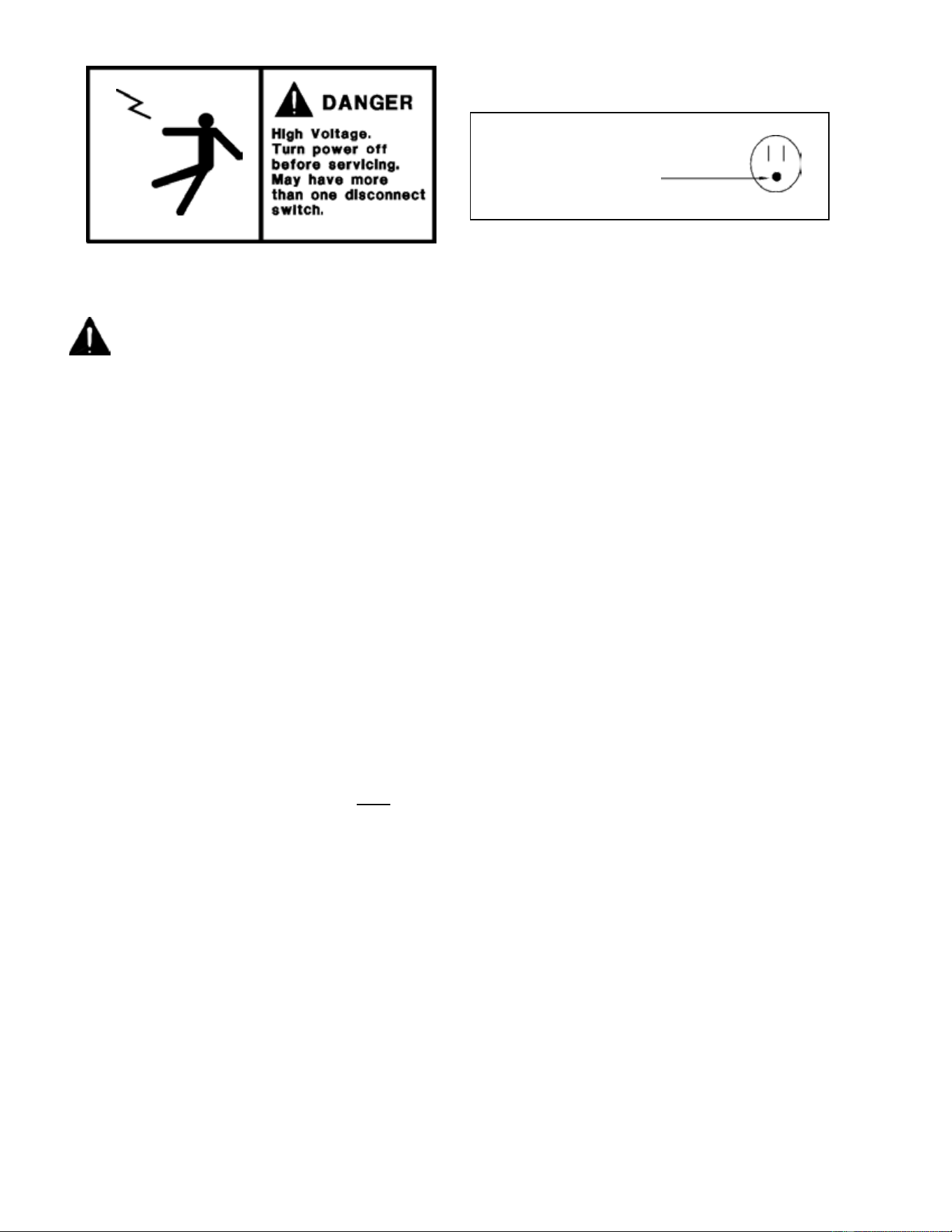
CAUTION!
GROUND REQUIRED
FOR SAFE OPERATION
This label is located on top of the electrical control This label is attached to the cabinet power cord
label and on the wiring channel. on models with a power cord.
NOTICE
• Do not store explosive substances such as aerosol cans with a flammable propellant in this appliance.
• WARNING: Keep clear of obstruction all ventilation openings in the appliance enclosure or in the structure
for building-in.
• WARNING: Do not use mechanical devices or other means to accelerate the defrosting process, other than
those recommended by the manufacturer.
• WARNING: Do not use electrical appliances inside the food/ice storage compartments unless they are of the
type recommended by the manufacturer.
• WARNING: Do not damage the refrigerating circuit.
INSPECTION FOR SHIPPING DAMAGE
You are responsible for filing all freight claims with the delivering truck line. Inspect all cartons and crates for damage as
soon as they arrive. If damage is noted to shipping crates or cartons or if a shortage is found, note this on the bill of
lading (all copies) prior to signing.
If damage is discovered when the cabinet is uncrated, immediately call the delivering truck line and follow up the call
with a written report indicating concealed damage to your shipment. Ask for an immediate inspection of your
concealed damage item. Crating material must be retained to show the inspector from the truck line.
57-02680- Rev. H All specifications within this publication subject to change without notice. © 2025 Master-Bilt Products, LLC. All rights reserved.
6
INSTALLATION INSTRUCTIONS
GENERAL INSTRUCTIONS
1. Be sure the equipment is properly installed by competent service people.
2. Keep the equipment clean and sanitary so it will meet your local sanitation codes.
3. Rotate your stock so that older stock does not accumulate. This is especially important for
ice cream. A "First-In, First-Out" rotation practice will keep the products in good salable
condition.
4. Do not place product in the case when it is soft or partially thawed. Also, product should not be put in the
case for at least 6 hours after it is started.
5. Stock cases as quickly as possible, exposing only small quantities to store temperatures for short
periods of time.
6. When replacing burned out LED, be sure that the electrical power to the lighting circuit is turned off.
NOTICE TO STORE OWNERS / MANAGERS
Moisture or liquid around or under the cabinet is a potential slip/fall hazard for persons walking by or
working in the general area of the cabinet. Any cabinet malfunction or housekeeping problem that creates a
slip/fall hazard around or under the cabinet should be corrected immediately.
If moisture or liquid is observed around or under a cabinet, an immediate investigation should be made by qualified
personnel to determine the source of the moisture or liquid. The investigation should determine if the cabinet is
malfunctioning or if there is a drainpipe leaking.
ELECTRICAL
WARNING
Before servicing electrical components in the case, make sure all power to case is off. Always use a
qualified technician.
NOTICE
For replacement ballast, use only ballast that complies with UL and recommended in part list.
57-02680- Rev. H All specifications within this publication subject to change without notice. © 2025 Master-Bilt Products, LLC. All rights reserved.
7
MECHANICAL
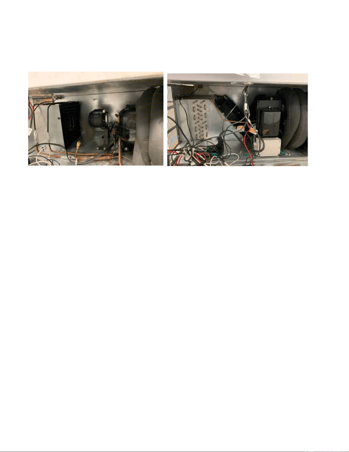
Remove grille and check refrigeration lines to see that they are free (not touching each other or
compressor). Spin condenser fan blade to see that it is free.
Check that all service valves are open.The picture below is standard DD series condensing unit. The compressor is
hermetic, it is internally spring mounted and ready to run.
Hermetic Compressors, jelly roll & fin and tube condenser
Remove cabinet from crate base and slide into location. The cabinet must be level from side to side and front to back.
To comply with Sanitation requirements the cabinet must be mounted on legs (6” high min.) or casters or the base
must be sealed to the floor with an N.S.F. listed silicone sealant.
STARTUP
Uncoil the lead cord and pass it through the hole in the grille.
While the cabinet is in operation, check the voltage draw and the amperage draw versus the rating on the
nameplate. Check the voltage at the compressor terminals while the compressor is starting. The unit is designed
to operate at +/- 10% of 115 volts, 60 cycle, single phase. Therefore, the voltage should be between 103 and
126.5 volts.
After the cabinet temperature has pulled down to approximately 0°F at the load line, check the thermostatic control
by turning it to its warmest position. This should shut the compressor off.
A separate 20 amp. fuse circuit for each cabinet is recommended to avoid the possibility of other appliances on a
circuit from overloading and causing a malfunction. Make sure that the electrical service is grounded upon
installation.

57-02680- Rev. H All specifications within this publication subject to change without notice. © 2025 Master-Bilt Products, LLC. All rights reserved.
8
REFRIGERANT EVACUATION AND CHARGING
When breaking into the refrigerant circuit to make repairs or any other purpose, use conventional procedures. However, for
flammable refrigerants it is important that best practice be followed, since flammability is a consideration.
Follow this procedure:
• Safely remove refrigerant following local and national regulations
• Purge the circuit with inert gas
• Evacuate (optional for A2L)
• Purge with inert gas (optional for A2L)
• Open the circuit by cutting or brazing
The refrigerant charge shall be recovered into the correct recovery cylinders if venting is not allowed by local and national
codes. For appliances containing flammable refrigerants, the system shall be purged with oxygen-free nitrogen to render
the appliance safe for flammable refrigerants. This process might need to be repeated several times. Compressed air or
oxygen shall not be used for purging refrigerant systems.
For appliances containing flammable refrigerants, refrigerants purging shall be achieved by breaking the vacuum in the
system with oxygen-free nitrogen and continuing to fill until the working pressure is achieved, then venting to atmosphere,
and finally pulling down to a vacuum (optional for A2L). This process shall be repeated until no refrigerant is within the
system (optional for A2L). When the final oxygen-free nitrogen charge is used, the system shall be vented down to
atmospheric pressure to enable work to take place.
Ensure that the outlet for the vacuum pump is not close to any potential ignition sources and that ventilation is available.
In addition to conventional charging procedures, follow these requirements:
• Ensure that contamination of different refrigerants does not occur when using charging equipment. Hoses or lines
shall be as short as possible to minimize the amount of refrigerant contained in them.
• Cylinders shall be kept in an appropriate position according to the instructions.
• Ensure that the REFRIGERATING SYSTEM is earthed prior to charging the system with refrigerant.
• Label the system when charging is complete (if not already).
• Extreme care shall be taken not to overfill the REFRIGERATING SYSTEM.
Prior to recharging the system, pressure test it with the appropriate purging gas. The system shall be leak-tested on
completion of charging but prior to commissioning. A follow up leak test shall be carried out prior to leaving the site.
57-02680- Rev. H All specifications within this publication subject to change without notice. © 2025 Master-Bilt Products, LLC. All rights reserved.
9
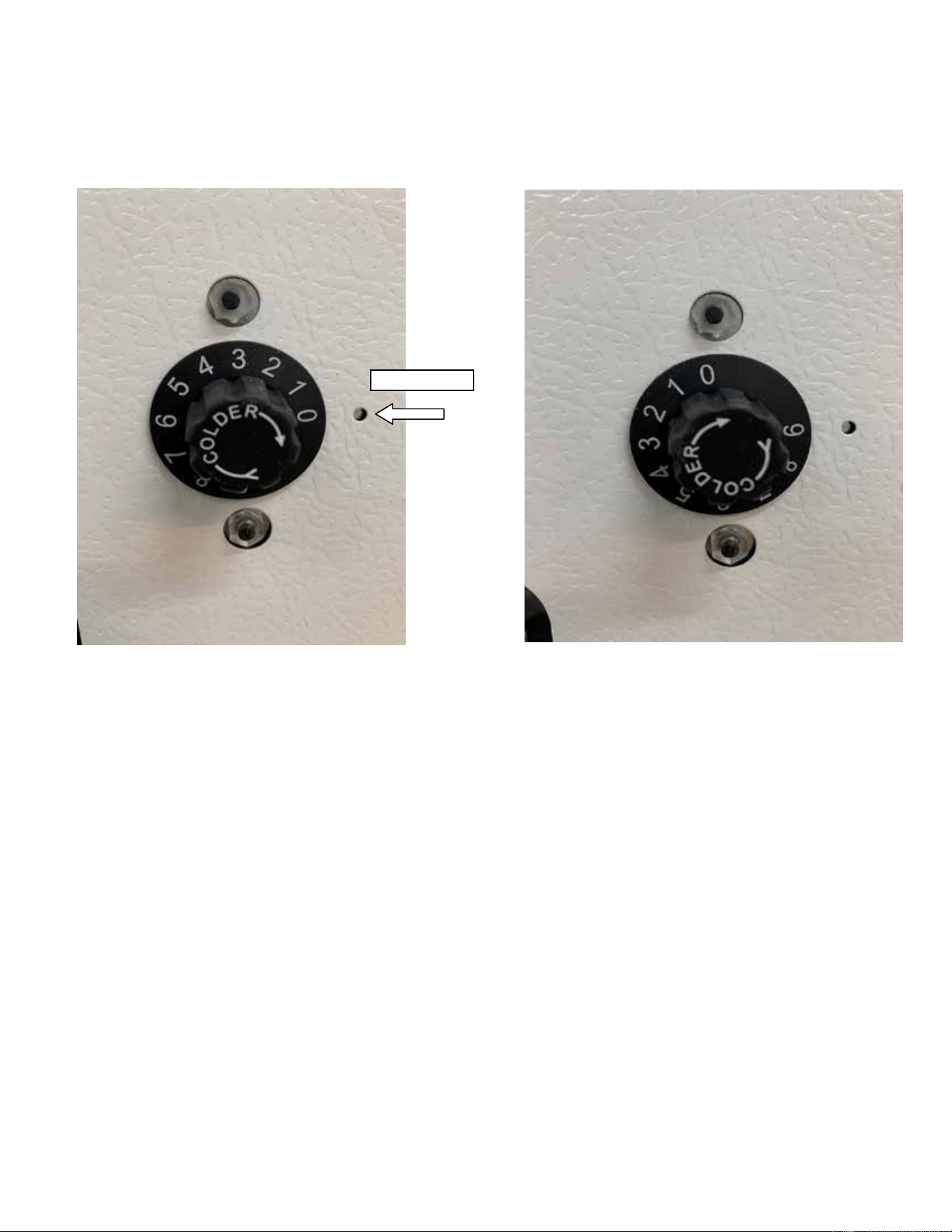
Punch Mark
TEMPERATURE CONTROL
The dipping-display cabinet has an adjustable temperature control from #1 (warmest setting) to # 9 (coldest
setting). Turn the control knob in line with the punch mark to the desired setting. The temperature control is located
near the condensing unit at the front of the cabinet.
WARMEST SETTING COLDEST SETTING
CLEANING INSTRUCTIONS
WARNING: DO NOT REMOVE FROST WITH A KNIFE, PICK, OR SHARP OBJECTS. DO NOT USE
ABRASIVE CLEANERS OR CAUSTIC CLEANERS OR SCOURING PADS
Every 30 to 60 days (depending on frost accumulation), the cabinet should be emptied, warmed up, and wiped
down using a solution of 1 teaspoon of baking soda with 1 quart of water. This solution will help eliminate odors.
Do not use strong soaps or detergents as they leave odors that can contaminate your product.
Cabinets are equipped with a floor drain that exits out the lower rear. The exit has a convenient garden hose fitting.
If it is not convenient to turn the cabinet power off, lay a piece of plastic sheeting on the floor of the cabinet and
scrape the frost off walls using a plastic scraper. Do not use metal scrapers. This will damage the interior paint of
the cabinet.
57-02680- Rev. H All specifications within this publication subject to change without notice. © 2025 Master-Bilt Products, LLC. All rights reserved.
10
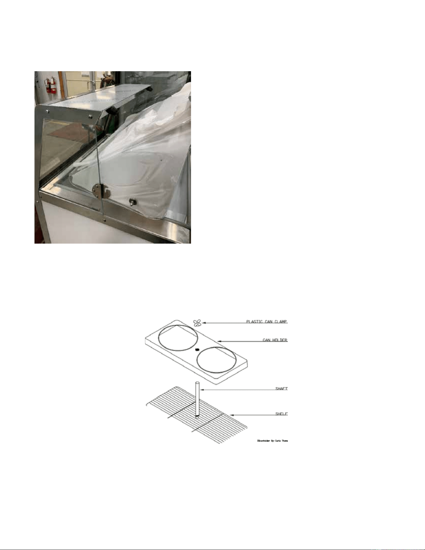
LID REMOVAL AND CLEANING
The lid can be removed by lifting up and out (see below). The lid is a high-impact plastic. Wash with warm soapy
water or non-abrasive detergent to avoid scratching.
CAN HOLDER ASSEMBLY REMOVAL AND CLEANING (OPTIONAL)
Remove plastic can clamp by screwing knob off the threaded shaft. Wash the can holder and can clamp with a non-
abrasive detergent to maintain sanitary gloss. Remove the shaft by loosening the wing nut and unscrewing the shaft
from the shelf. Wash the shaft and shelf using a non-metallic brush.
57-02680- Rev. H All specifications within this publication subject to change without notice. © 2025 Master-Bilt Products, LLC. All rights reserved.
11
FROST SHIELD REMOVAL AND CLEANING (OPTIONAL)
When the frost-shields accumulate approximately ½ to 1 inch of frost (about two to three days), remove it by lifting
up to disengage from the keyhole slot. Remove the frost by holding under running water until clean. Dry and replace
the frost-shield by engaging screws at the big end of the keyhole and push down.
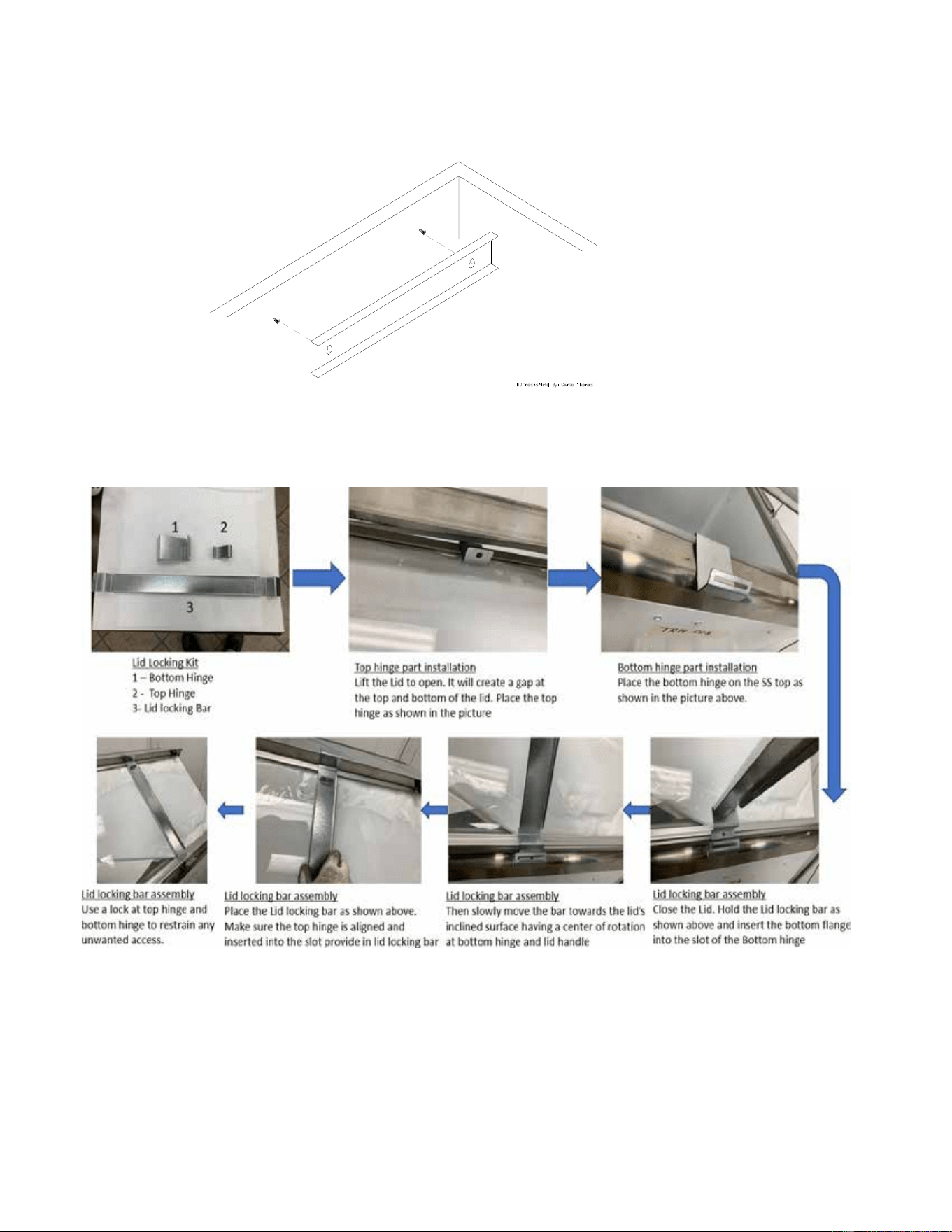
LID LOCKING KIT INSTALLATION (OPTIONAL)
The optional lid locking kit secures ice cream stored inside the cabinet. One kit is required for each lid.
Follow the process in reverse to disassemble.

57-02680- Rev. H All specifications within this publication subject to change without notice. © 2025 Master-Bilt Products, LLC. All rights reserved.
12
OPERATION CONDITIONS AND PRESSURES
With room ambient temperature of +75
o
F and cold cabinet (unit cycling on control):
DD-66/DD-66L/DD-66LCG & DD-88/DD-88L/DD-88LCG with R-290 refrigerant
• Suction pressure – 2 to 4 psig.
• Head pressure – 130 to 160 psig.
DD-26/DD-26L/DD-26LCG & DD-46/DD-46L/DD-46LCG with R-290 refrigerant
• Suctions pressure 1 to 5 psig
• Head pressure 130 to 160 psig
TECHNICIAN’S CONSIDERATIONS
Technicians should:
• Have an EPA 608 certification type 1 to work on this cabinet.
• Exercise caution when disconnecting quick-connects or opening refrigerant circuits.
• Use ventilation fans anytime a refrigeration circuit is opened.
• Survey the area for ignition sources before opening a refrigeration circuit.
• Correct all nearby electrical faults and discharge all capacitors before opening a refrigeration circuit.
• Avoid working in confined spaces with A3 refrigerants. Ventilation should be used if necessary.
• Check the area for flammable refrigerants with an approved leak detector to find present refrigerant before starting
work. This leak detection equipment should not be arcing or sparking. It should be intrinsically safe.
• Have a fire extinguisher present during service and installation. A dry chemical or CO
2 fire extinguisher should be
adjacent to the charging area.
No person carrying out work in relation to a REFRIGERATING SYSTEM which involves exposing any pipe work shall use
any sources of ignition in such a manner that it may lead to the risk of fire or explosion.
All possible ignition sources, including cigarettes, should be kept sufficiently far away from the site of installation, repairing,
removing and disposal, during which refrigerant can possibly be released to the surrounding space.
Prior to work taking place, the area around the equipment shall be surveyed to make sure that there are no flammable
hazards or ignition risks. "No Smoking" signs shall be displayed.
Technicians should ensure that the area is in the open or that it is adequately ventilated before breaking into the system or
conducting any hot work. A degree of ventilation shall continue during the period that the work is carried out. The ventilation
should safely disperse any released refrigerant and preferably expel it externally.
Where electrical components are being charged, they shall be fit for the purpose and to the correct specification. At all
times, the manufacturer's maintenance and service guidelines shall be followed. If in doubt, consult the manufacturer's
technical department for assistance.
FLAMMABLE REFRIGERANT CONSIDERATIONS
The following checks shall be applied to installations using FLAMMABLE REFRIGERANTS:

57-02680- Rev. H All specifications within this publication subject to change without notice. © 2025 Master-Bilt Products, LLC. All rights reserved.
13
• The actual REFRIGERANT CHARGE is in accordance with the room size within which the refrigerant-containing
parts are installed.
• The ventilation machinery and outlets are operating adequately and are not obstructed.
• If an indirect refrigerating circuit is being used, the secondary circuit shall be checked for the presence of
refrigerant.
• Marking to the equipment continues to be visible and legible. Markings and signs that are illegible shall be
corrected.
• Refrigerating pipes or components are installed in a position where they are unlikely to be exposed to any
substance which may corrode refrigerant containing purpose and to the correct specification. At all times, the
manufacturer's maintenance and service guidelines shall be followed. If in doubt, consult the manufacturer's
technical department for assistance.
CHECKING ELECTRICAL DEVICES
• Repair and maintenance to electrical components shall include initial safety checks and component inspection
procedures.
• If a fault exists that could compromise safety, then no electrical supply shall be connected to the circuit until it is
satisfactorily dealt with.
• If the fault cannot be corrected immediately but it is necessary to continue operation, an adequate temporary solution
shall be used. This shall be reported to the owner of the equipment, so all parties are advised.
INITIAL SAFETY CHECKS
• Ensure the capacitors are discharged. This shall be done in a safe manner to avoid possibility of sparking.
• Ensure no live electrical components and wiring are exposed while charging, recovering or purging the system.
• Ensure there is continuity of earth bonding.
During repairs, technicians should ensure all electrical supplies shall be disconnected from the equipment being worked
upon prior to any removal of sealed covers, etc.
LEAK DETECTION
If it is necessary to have an electrical supply to equipment during service, then a permanently operating form of leak
detection shall be located at the most critical point.
Technicians should ensure cabling will not be subject to wear, corrosion, excessive pressure, vibration, sharp edges, or
any other adverse environmental effects. The effects of aging or continual vibration from sources such as compressors or
fans should also be considered.
Under no circumstances shall potential sources of ignition be used in the searching for or detection of refrigerant leaks. A
halide torch (or any other detector using a naked flame) shall not be used.
The following leak detection methods are deemed acceptable for all refrigerant systems:
• Electronic leak detectors may be used to detect refrigerant leaks but, in the case of FLAMMABLE REFRIGERANTS,
the sensitivity might not be adequate or might need recalibration.
• Detection equipment shall be calibrated in a refrigerant-free area.
• Ensure that the detector is not a potential source of ignition and is suitable for the refrigerant used.

57-02680- Rev. H All specifications within this publication subject to change without notice. © 2025 Master-Bilt Products, LLC. All rights reserved.
14
• Leak detection equipment shall be set at a percentage of the LFL of the refrigerant and shall be calibrated to the
refrigerant employed, and the appropriate percentage of gas (25 % maximum) is confirmed.
• Leak detection fluids are also suitable for use with most refrigerants but the use of detergents containing chlorine
shall be avoided as the chlorine can react with the refrigerant and corrode the copper pipework.
Examples of leak detection fluids include bubble method and fluorescent method agents.
If a leak is suspected, all naked flames shall be extinguished. If a leakage of refrigerant is found which requires brazing, all
the refrigerant shall be recovered from the system. Removal of refrigerant shall be according to Clause 101.DVS.9 in
UL60335-2-89.
SERVICE INSTRUCTIONS
Prior to beginning work on systems containing FLAMMABLE REFRIGERANTS, safety checks are necessary to
ensure that the risk of ignition is minimized. Work shall be undertaken under a controlled procedure to minimize the
risk of a
flammable gas or vapor being present while the work is being performed.
All maintenance staff and others working in the local area shall be instructed on the nature of work being carried out.
Work in confined spaces shall be avoided. The area shall be checked with an appropriate refrigerant detector prior to
and during
work, to ensure the technician is aware of potentially toxic or flammable atmospheres.
Ensure that the leak detection equipment being used is suitable for use with all applicable refrigerants, i.e., non-
sparking, adequately sealed, or intrinsically safe. Under no circumstances shall potential sources of ignition be used
in the searching for or detection of refrigerant leaks. A halide torch (or any other detector using a naked flame) shall
not be used.
If any hot work is to be conducted on the refrigerating equipment or any associated parts, appropriate fire
extinguishing equipment shall be available on hand. A dry chemical or CO2 fire extinguisher should be adjacent to the
charging area.
No person carrying out work in relation to a REFRIGERATING SYSTEM which involves exposing any pipe work shall
use any sources of ignition in such a manner that it may lead to the risk of fire or explosion.
All possible ignition sources, including cigarette smoking, should be kept sufficiently far away from the site of
installation, repairing, removing and disposal, during which refrigerant can possibly be released to the surrounding
space.
Prior to work taking place, the area around the equipment shall be surveyed to make sure that there are no flammable
hazards or ignition risks. “No Smoking” signs shall be displayed.
Ensure that the area is in the open or that it is adequately ventilated before breaking into the system or conducting
any hot work. A degree of ventilation shall continue during the period that the work is carried out. The ventilation
should safely disperse any released refrigerant and preferably expel it externally into the atmosphere.
Where electrical components are being changed, they shall be fit for the purpose and to the correct specification. At
all times, the manufacturer’s maintenance and service guidelines shall be followed. If in doubt, consult the
manufacturer’s technical department for assistance.
The following checks shall be applied to installations using FLAMMABLE REFRIGERANTS:
• The actual REFRIGERANT CHARGE is in accordance with the room size within which the refrigerant containing
parts are installed

57-02680- Rev. H All specifications within this publication subject to change without notice. © 2025 Master-Bilt Products, LLC. All rights reserved.
15
• The ventilation machinery and outlets are operating adequately and are not obstructed
• If an indirect refrigerating circuit is being used, the secondary circuit shall be checked for the presence of refrigerant
• Marking to the equipment continues to be visible and legible. Markings and signs that are illegible shall be corrected
• Refrigerating pipe or components are installed in a position where they are unlikely to be exposed to any substance
which may corrode refrigerant containing parts
Repair and maintenance to electrical components shall include initial safety checks and component inspection
procedures. If a fault exists that could compromise safety, then no electrical supply shall be connected to the circuit
until it is satisfactorily dealt with.
If the fault cannot be corrected immediately but it is necessary to continue operation, an adequate temporary solution
shall be used. This shall be reported to the owner of the equipment, so all parties are advised.
Initial safety checks shall include:
• That capacitors are discharged: this shall be done in a safe manner to avoid possibility of sparking
• That no live electrical components and wiring are exposed while charging, recovering or purging the system
• That there is continuity of earth bonding.
TROUBLESHOOTING GUIDE
1. High head pressure and high back pressure:
A. Condenser coil clogged or restricted.
B. Condenser fan motor defective.
C. Air in the system.
D. Refrigeration overcharge.
2. Low back pressure and low head pressure:
A. Capillary tube restriction.
B. Refrigerant undercharged.
C. Leak in system.
D. Moisture in system.
3. Pressures normal – cabinet warm:
A. Refrigerant undercharged.
B. Thermostat set too warm.
4. Compressor starts and runs – but cycles on overload:
A. Low voltage.
B. Overload protector defective.
C. High head pressure (see #1).
5. Compressor will not start – hums, but cycles on overload:
A. Low voltage.
B. Relay defective.
C. Overload defective.
D. High head pressure (see #1).
6. Cabinet sweating:
A. High ambient humidity.
57-02680- Rev. H All specifications within this publication subject to change without notice. © 2025 Master-Bilt Products, LLC. All rights reserved.
16
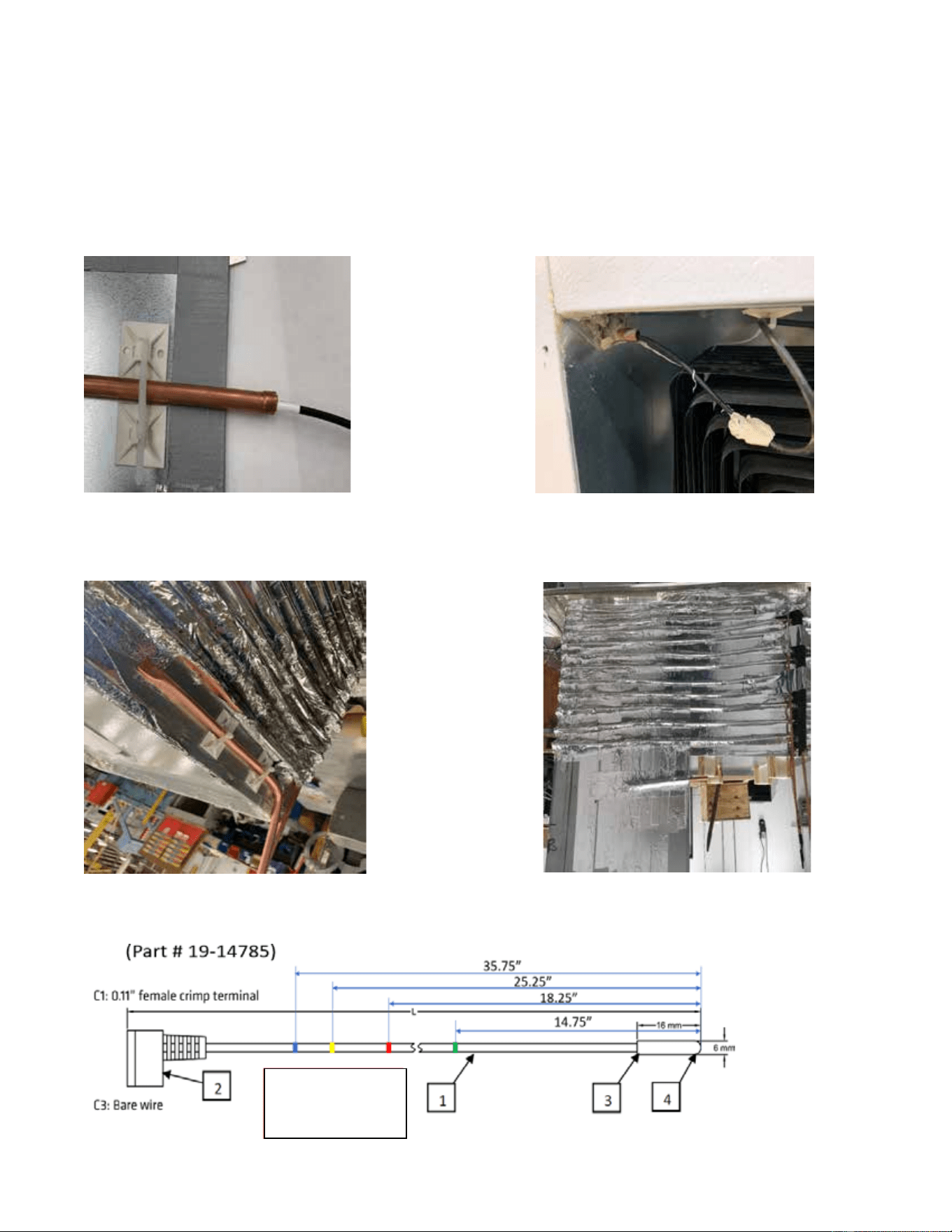
Bulb well location with sensor probe
(representation only)
Sensor probe with bulb well foamed
Bulb well in DD-26
Bulb well location in DD-46, DD-66
& DD-88
Red: DD-26
Green: DD-46
Yellow: DD-66
Blue: DD-88
CONTROLLER SENSOR PROBE LOCATION
In DD-46/DD-46L/DD-46LCG, DD-66/DD-66L/DD-66LCG and DD-88/DD-88L/DD-88LCG models, the bulb well is
a straight 3/8” copper tube placed 3” below the condensing unit compartment as shown below. For the DD-
26/DD-26L/DD-26LCG model, the bulb well is an inverted “L” shape as shown below. Make sure the bulb well
opening is properly insulated with permagum. While replacing the sensor probe, make sure the probe is inserted
to the end of the bulb well until it stops. Be careful when inserting the probe inside the bulb well to avoid damage.
The sensor probe is color coded as shown below. Make sure the probe is fully inserted into the bulb well
to the mark up.
57-02680- Rev. H All specifications within this publication subject to change without notice. © 2025 Master-Bilt Products, LLC. All rights reserved.
17
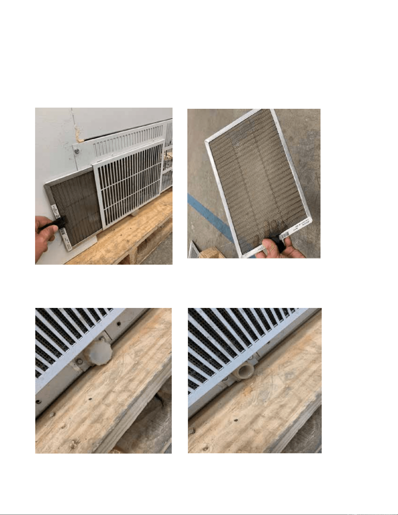
AIR FILTER CLEANING INSTRUCTIONS
(Air Filter for DD-66/DD-66L/DD-66LCG & DD-88/DD-88L/DD-88LCG Fin & Tube Condenser)
DD-66 and DD-88 models are equipped with a 5mm fin and tube condenser. A removable and reusable air filter
protects the condenser and prevents dust blockage. Remove and clean the filter periodically for optimum
performance of the unit. See the removal and reinstallation instructions below.
DRAINING SYSTEM
See below for location of the drain outlet.
If moisture or liquid is observed around or under the cabinet, qualified personnel should investigate immediately to
57-02680- Rev. H All specifications within this publication subject to change without notice. © 2025 Master-Bilt Products, LLC. All rights reserved.
18
determine its source. The investigation should determine if the cabinet is malfunctioning or if there is a simple
housekeeping problem.
Moisture or liquid around or under a cabinet is a potential slip/fall hazard for people walking by or working in the general
area of the cabinet.
Any cabinet malfunction or housekeeping problem that creates a slip/fall hazard around or under a cabinet should be
corrected immediately.
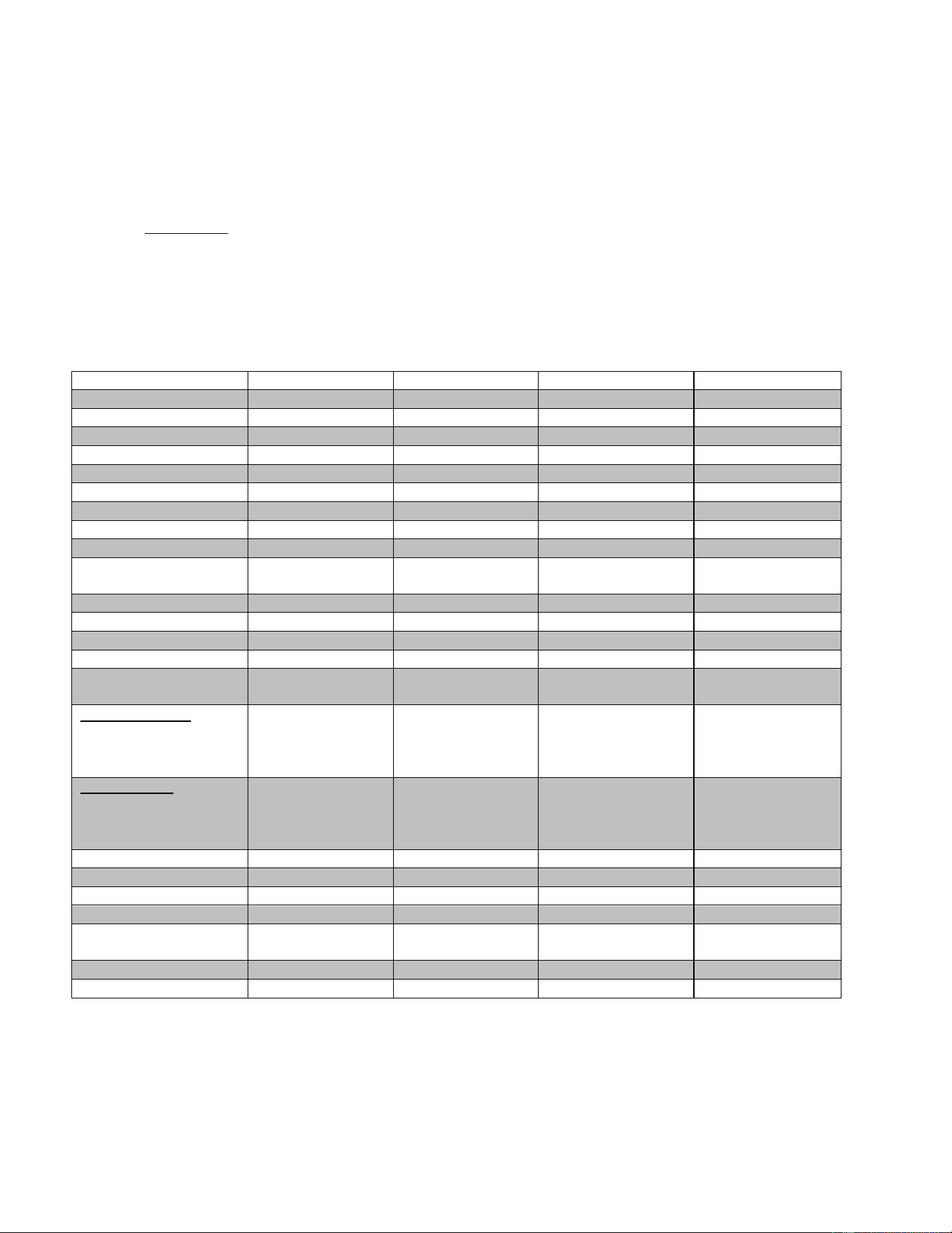
DIPPING-DISPLAY CABINET PART NUMBERS
Please use the part numbers below when ordering replacement parts for your DD Series Standard, Low Glass
and Low Curved Glass Models so as to minimize the risk of possible ignition due to incorrect parts.
Description
DD-26(L)(LCG)
DD-46(L)(LCG)
DD-66(L)(LCG)
DD-88(L)(LCG)
LED Driver
23-01878
23-01878
23-01878
23-01878
LED
23-01947
23-01945
23-01947(2 REQ)
23-01950(2 REQ)
Jumper
23-01951
23-01951
Bracket/Attachment
23-01948
23-01948
23-01948
23-01948
Capillary Tube
11-01306
11-01306
11-01306 (2 REQ)
11-01306 (2 REQ)
Compressor
03-50992
03-50992
03-50996
03-50996
Condenser Coil
07-14190
07-14190
07-14186
07-14186
Condenser Fan Blade
15-13093
15-13093
Condenser Fan Motor
13-00311
13-00311
13-13453
13-13453
Condenser Fan Motor
Bracket
13-00754 13-00754
Compressor grommet
03-50994
03-50994
03-50994
03-50994
Drier
09-09864
09-09864
09-09864
09-09864
Controller
19-14239
19-14239
19-14239
19-14239
Controller Sensor
19-14785
19-14785
19-14785
19-14785
Top Gasket
(37-01544)(37-
(37-01545)(37-
(37-01546)(37-
(37-01547)(37-
01536)
01537)
01538)
01539)
FRONT GLASS
(Straight Glass Model)
31-03991
31-03992
31-03993
31-03994
(Low Glass Model)
31-03976
31-03977
31-03978
31-03979
(Low Curved Glass)
31-04011
31-04012
31-04013
31-04014
SIDE GLASS
(Straight Glass Model)
31-03995
31-03995
31-03995
31-03995
(Low Glass Model)
31-03480
31-03480
31-03480
31-03480
(Low Curved Glass)
31-04015
31-04015
31-04015
31-04015
Lid Assembly
A394-14500
A395-14500
A396-14500*
A397-14500*
Light Switch
19-14810
19-14810
19-14810
19-14810
Shelf, Wire
33-01879
33-01879
33-01879
33-01879
Recess Bumper
29-01691
29-01691
29-01691
29-01691
Wire Harness (126”
Power Cord)
21-01741 21-01741 21-01741 21-01741
Condenser Air Filter
44-01140
44-01140
Distributor
11-02006
11-02006
*Two lid assemblies required for this model.
57-02680- Rev. H All specifications within this publication subject to change without notice. © 2025 Master-Bilt Products, LLC. All rights reserved.
19
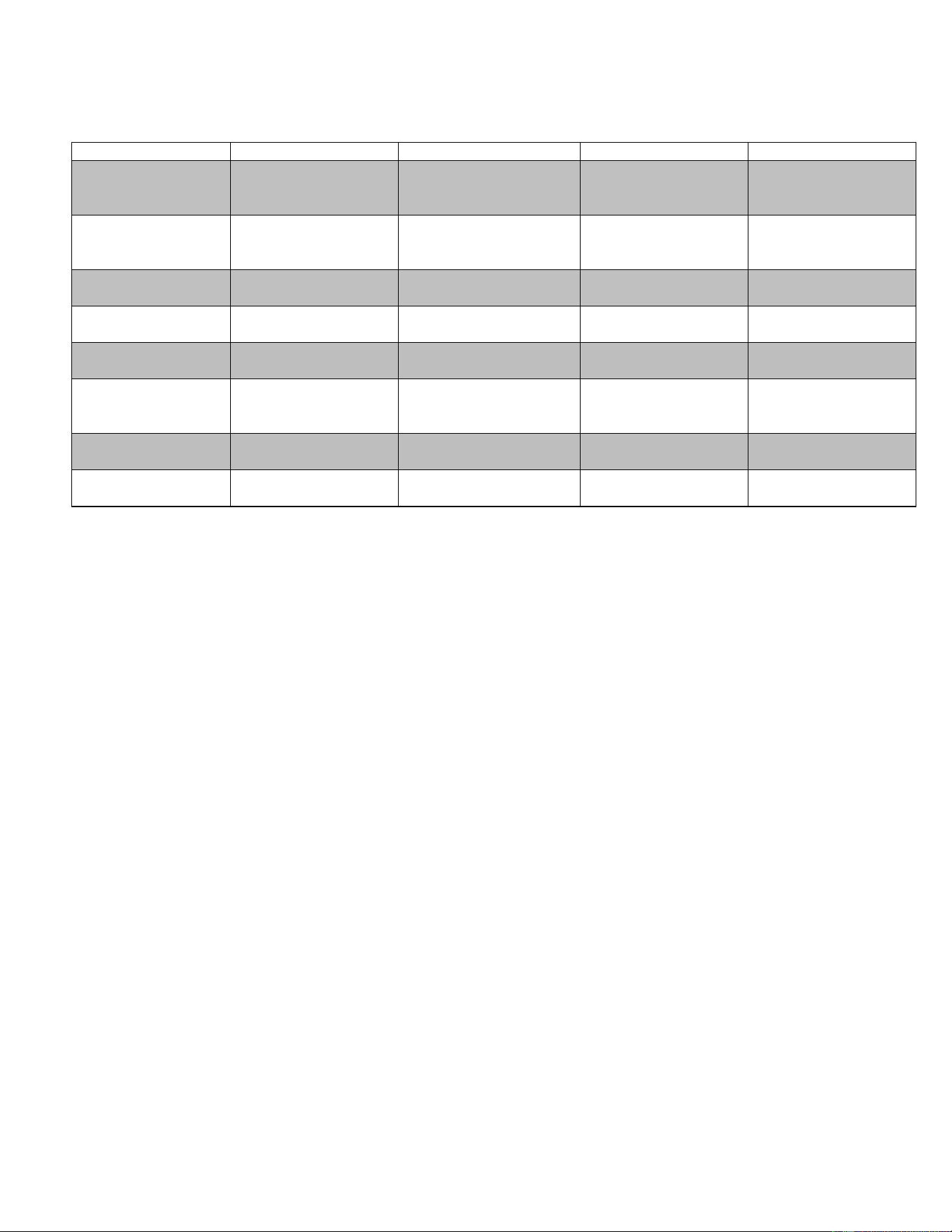
OPTIONS
Description
DD-26(L/LCG)
DD-46(L/LCG)
DD-66(L/LCG)
DD-88(L/LCG)
Can Holders –
Includes
White Can Covers
A394-20301
A395-20301
A396-20301
A397-20301
Can Covers
Clear
White
44-00984
44-01084
44-00984
44-01084
44-00984
44-01084
44-00984
44-01084
Lid Locking Kit
A390-11129
A390-11129
A390-11129
(2 QTY)
A390-11129
(2 QTY)
Casters
Set (4 or 6), 3” Dia.
A039-11140
A039-11140
A044-11140
A044-11140
Dipper Well
w/Installation Kit
A060-20400 A060-20400 A060-20400 A060-20400
Frost Shields
(Patented)
A390-11150 (DD-26),
A394-11150 (DD-26L
& DD-26LCG)
A391-11150 (DD-46),
A395-11150 (DD-46L &
DD-46LCG)
A392-11150 (DD-66),
A396-11150 (DD-66L
& DD-66LCG)
A393-11150 (DD-88),
A397-11150 (DD-88L
& DD-88LCG)
Legs
6” leg kit
A039-11170 A039-11170 A044-11140 A044-11140
Flavor Tags
A062-20225
(DD-26 only)
A062-20225
(DD-46 only)
A062-20225
(DD-66 only)
A062-20225
(DD-88 only)
DECOMMISSIONING, SALE AND DISPOSAL
If you sell or give away your dipping cabinet, you must make sure that all safety labels and the installation and service
manual are included with it. If you need replacement labels or manuals, contact the customer service department.
The customer service department should be contacted at the time of sale or disposal of your cabinet so records may be
kept of its new location.
If you sell or give away your cabinet and you evacuate the refrigerant charge before shipment, the refrigerant charge
must be properly recovered in compliance with section 608 of the Clean Air Act, effective November 1995, and in
accordance with all applicable local, regional, or national standards.
Before conducting this procedure, make sure the technician is familiar with the equipment. Prior to the task being
conducted, an oil and refrigerant sample must be taken in case analysis is required prior to re-use of recovered refrigerant.
It is essential that electrical power is available before starting the task.
• Isolate the system electrically.
• Before attempting the procedure, ensure that:
o Mechanical handling equipment is available, if required, for handling refrigerant cylinders
o All personal protective equipment is available and being used correctly
o The recovery process is supervised at all times by a competent person
o Recovery equipment and cylinders conform to the appropriate standards
• Pump down refrigerant system, if possible.
• If a vacuum is not possible, make a manifold so that refrigerant can be removed from various parts of the system.
• Make sure that cylinder is situated on the scales before recovery takes place.
• Start the recovery machine and operate in accordance with instructions.

57-02680- Rev. H All specifications within this publication subject to change without notice. © 2025 Master-Bilt Products, LLC. All rights reserved.
20
• Do not overfill cylinders (no more than 80% volume liquid charge).
• Do not exceed the maximum working pressure of the cylinder, even temporarily.
• When the cylinders have been filled correctly and the process completed, make sure that the cylinders and the
equipment are removed from site promptly and all isolation valves on the equipment are closed off.
• Recovered refrigerant shall not be charged into another REFRIGERATING SYSTEM unless it has been cleaned and
checked.
Equipment shall be labeled stating that it has been de-commissioned and emptied of refrigerant. The label shall be dated
and signed. For appliances containing FLAMMABLE REFRIGERANTS, ensure that there are labels on the equipment
stating the equipment contains FLAMMABLE REFRIGERANT.
57-02680- Rev. H All specifications within this publication subject to change without notice. © 2025 Master-Bilt Products, LLC. All rights reserved.
21
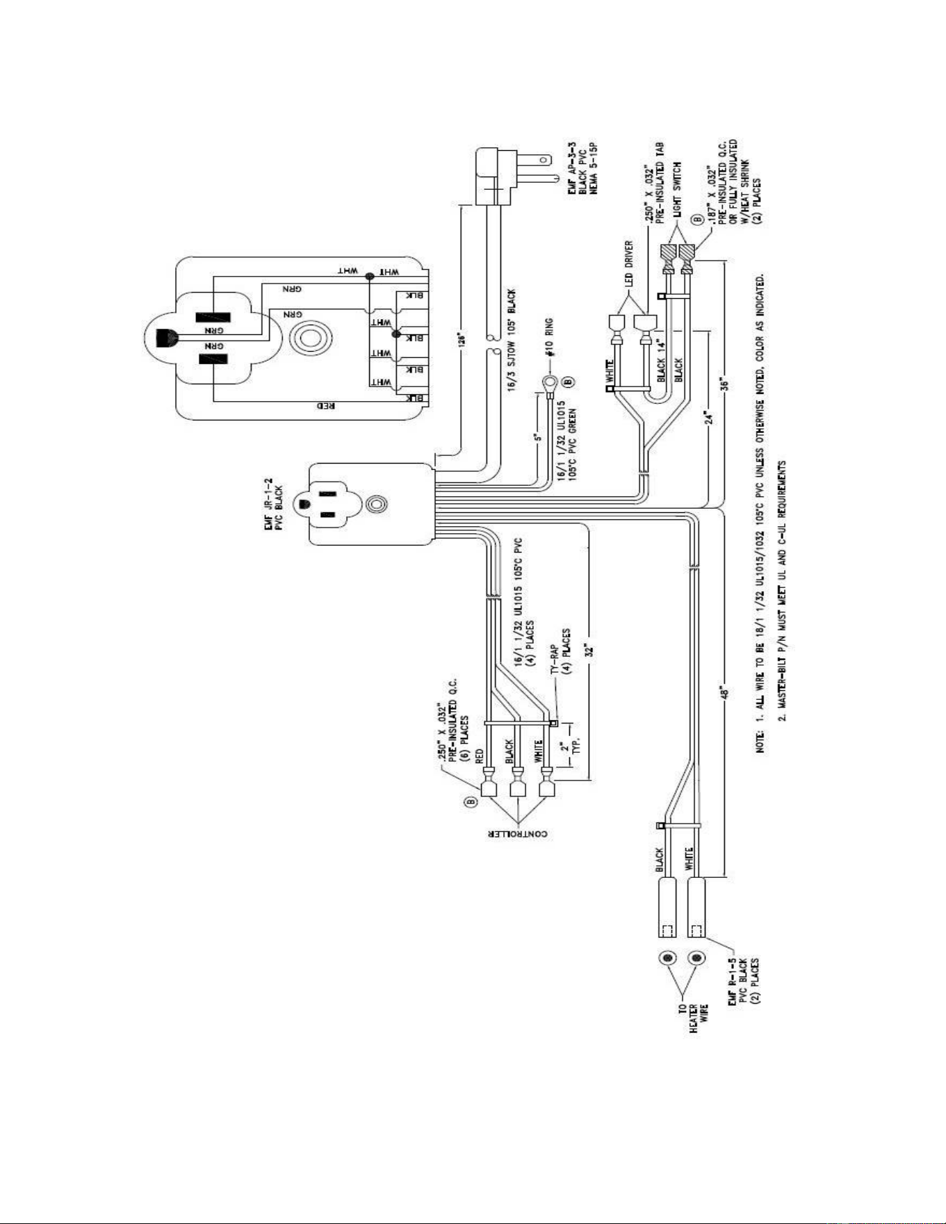
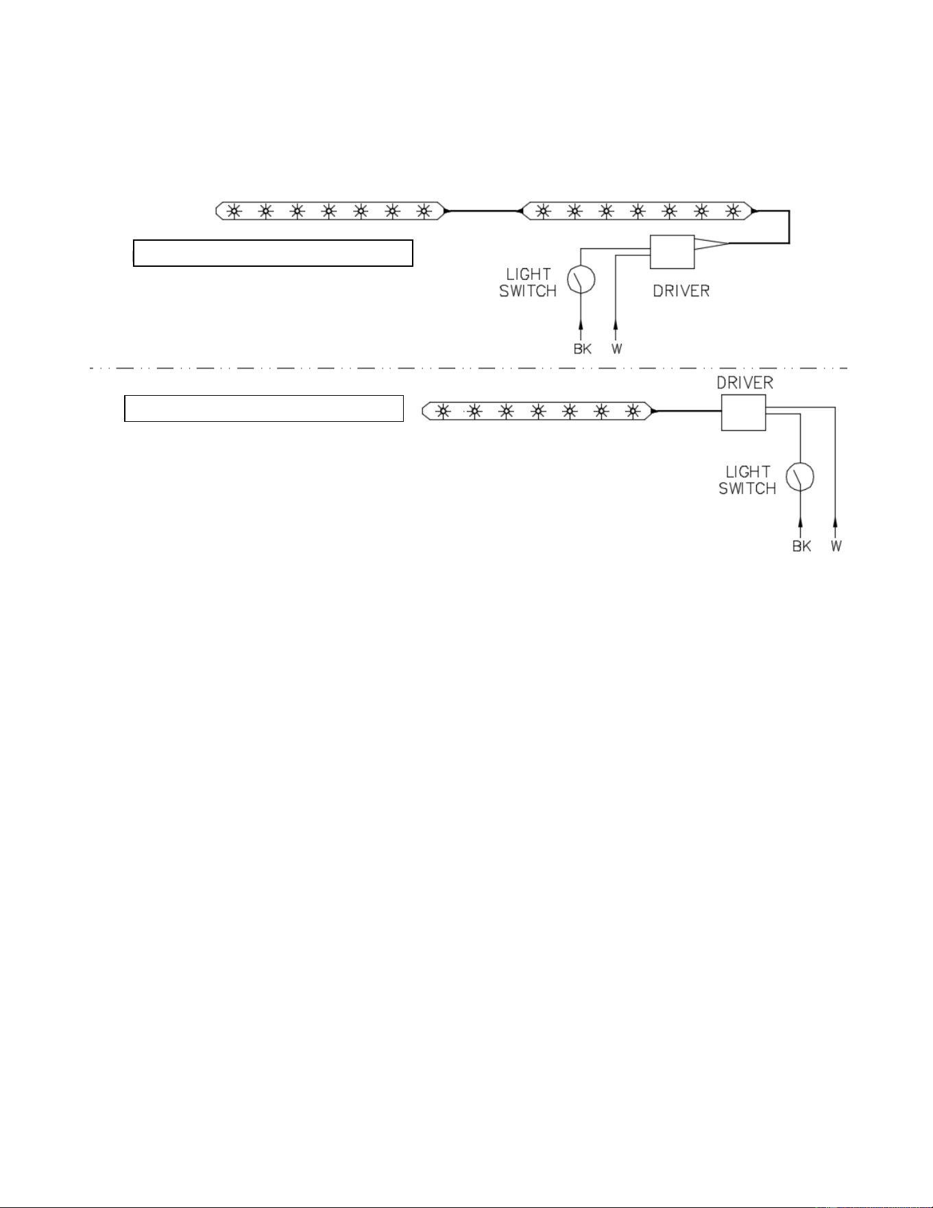
WIRING DIAGRAMS
WIRING HARNESS WITH MOLDED JUNCTION ASSEMBLY
57-02680- Rev. H All specifications within this publication subject to change without notice. © 2025 Master-Bilt Products, LLC. All rights reserved.
22
LIGHT WIRING FOR DD-26 & DD-46
LIGHT WIRING FOR DD-66 & DD-88
LED CONNECTION
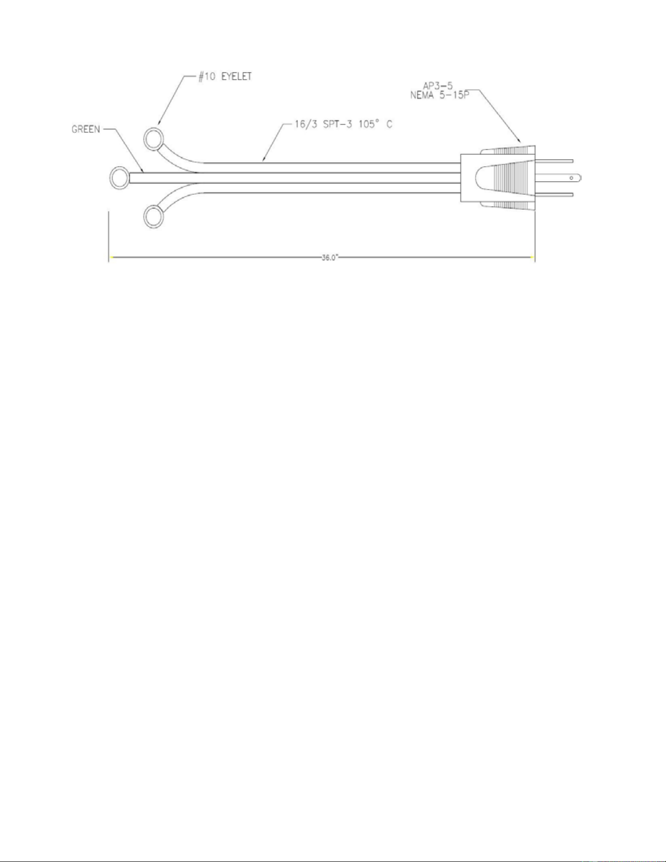
POWER CORD TO CONNECT CONDENSING UNIT
57-02680- Rev. H All specifications within this publication subject to change without notice. © 2025 Master-Bilt Products, LLC. All rights reserved.
23
MOLDED JUNCTION ASSEMBLY
FOR COMPRESSOR WIRING CONNECTION, PLEASE REFER TO THE
COMPRESSOR MANUFACTURER WIRING DIAGRAM
57-02680- Rev. H All specifications within this publication subject to change without notice. © 2025 Master-Bilt Products, LLC. All rights reserved.
24
Master-Bilt
908 Highway 15 North
New Albany, MS 38652
800-647-1284 Sales
800-684-8988 Parts/Service