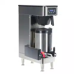
Premia
™
Bean-to-Batch Medium to High Volume Coffee Brewer
For Technical Service, contact Bunn-O-Matic Corporation at 1-800-286-6070.
INSTALLATION & OPERATING GUIDE
Bunn-O-Matic Corporation
Post Office Box 3227, Springfield, Illinois 62708-3227
Phone (217) 529-6601 | Fax (217) 529-6644
59224.0000 B 4/25 © 2025 Bunn-O-Matic Corporation
www.bunn.com
After Initial Setup, if you
have a USB Stick with
custom configuration
files, see install steps
starting on page 43.
with Auto Clean

Bunn-O-Matic Corp. (“BUNN”) warrants the BUNN Premia
™
as further described below for a warranty period of 1 year
parts and labor. All coffee servers/reservoirs – 1 year parts and labor.
For customers subscribed to BUNNlink
®
, BUNN reserves the right to periodically auto-push critical software updates
that will enhance functionality or performance of the BUNN equipment, unless the customer requests advance notice
of such software updates from BUNN in writing.
These warranty periods run from the date of installation. BUNN warrants that the equipment manufactured by it will
be commercially free of defects in material and workmanship existing at the time of manufacture and appearing
within the applicable warranty period. This warranty does not apply to any equipment, component or part that was
not manufactured by BUNN or that, in BUNN’s judgment, has been affected by misuse, neglect, alteration, improper
installation or operation, improper maintenance or repair, non periodic cleaning and descaling, equipment failures
related to poor water quality, damage or casualty. This warranty is conditioned on the Buyer 1) giving BUNN prompt
notice of any claim to be made under this warranty by telephone at (217) 529-6601 or by writing to Post Office Box
3227, Springfield, Illinois 62708-3227; 2) if requested by BUNN, shipping the defective equipment prepaid to an
authorized BUNN service location; and 3) receiving prior authorization from BUNN that the defective equipment is
under warranty. Additionally, the following is excluded from the warranty period:
Warranty Exclusions:
• Parts such as, but not limited to, hoppers and lids, drip trays, touch screens (fail due to damage), hinges and
plastic parts damaged due to improper handling or cleaning agents.
• Replacement of wear items such as, but not limited to, O-rings, gaskets, filter screens, silicone tubes, hoses,
and valve seats.
• Repairs made necessary due to poor water quality such as dispense valves, water inlet valves, scaling in hot
water boilers (Carbonate Hardness range of 40 - 140 ppm constant).
• Improper voltage, (See equipment operations manual for voltage specifications).
• Failure to use BUNN approved cleaning supplies constitutes improper maintenance.
• Failure to have required preventive maintenance performed by a BUNN technician or authorized Fast Cup
service provider.
• Parts replaced under the terms of this warranty carry the remainder of the machine’s parts warranty term, or 90
days, whichever is greater.
THE FOREGOING WARRANTY IS EXCLUSIVE AND IS IN LIEU OF ANY OTHER WARRANTY, WRITTEN OR
ORAL, EXPRESS OR IMPLIED, INCLUDING, BUT NOT LIMITED TO, ANY IMPLIED WARRANTY OF EITHER
MERCHANTABILITY OR FITNESS FOR A PARTICULAR PURPOSE.
The agents, dealers or employees of BUNN are not authorized to make modifications to this warranty or to make
additional warranties that are binding on BUNN. Accordingly, statements by such individuals, whether oral or written,
do not constitute warranties and should not be relied upon.
If BUNN determines in its sole discretion that the equipment does not conform to the warranty, BUNN, at its exclusive
option while the equipment is under warranty, shall either 1) provide at no charge replacement parts and/or labor
(during the applicable parts and labor warranty periods specified above) to repair the defective components, provided
that this repair is done by a BUNN Authorized Service Representative; or 2) shall replace the equipment or refund the
purchase price for the equipment.
THE BUYER’S REMEDY AGAINST BUNN FOR THE BREACH OF ANY OBLIGATION ARISING OUT OF THE
SALE OF THIS EQUIPMENT, WHETHER DERIVED FROM WARRANTY OR OTHERWISE, SHALL BE LIMITED, AT
BUNN’S SOLE OPTION AS SPECIFIED HEREIN, TO REPAIR, REPLACEMENT OR REFUND.
In no event shall BUNN be liable for any other damage or loss, including, but not limited to, lost profits, lost sales, loss
of use of equipment, claims of Buyer’s customers, cost of capital, cost of down time, cost of substitute equipment,
facilities or services, or any other special, incidental or consequential damages.
BUNN-O-MATIC COMMERCIAL PRODUCT WARRANTY

3
CONTENTS
BUNN-O-MATIC COMMERCIAL PRODUCT WARRANTY ......................................................................................2
USER NOTICES ........................................................................................................................................................ 4
NORTH AMERICAN REQUIREMENTS .................................................................................................................... 5
CE REQUIREMENTS ................................................................................................................................................5
SUPPORT .................................................................................................................................................................6
BUNN SupportHub .................................................................................................................................................6
SITE REQUIREMENTS ............................................................................................................................................. 6
Plumbing ................................................................................................................................................................6
Water Treatment ..................................................................................................................................................... 6
FOR INDOOR USE ONLY .........................................................................................................................................6
Counter...................................................................................................................................................................6
INITIAL SETUP .........................................................................................................................................................7
Electrical Configuration ..........................................................................................................................................7
Optional Field Wiring ..............................................................................................................................................8
Electrical Configuration .......................................................................................................................................8
Drain and Waste Bin Setup ....................................................................................................................................9
Countertop Template ..............................................................................................................................................9
Preparing Countertop ............................................................................................................................................. 9
Connect Hoses and Tubes ...................................................................................................................................10
Cleaner Tube ..................................................................................................................................................... 10
Tempering Drain Hose ...................................................................................................................................... 11
Drip Tray Drain Hose......................................................................................................................................... 11
Hoses and Tubes Through counter ................................................................................................................... 11
Install Undercounter Components ....................................................................................................................... 12
Drain Hose Branch ........................................................................................................................................... 12
Cleaning Liquid ................................................................................................................................................. 13
Coffee Grounds Bucket..................................................................................................................................... 14
Water filtration ................................................................................................................................................... 14
Plumbing Hook Up ............................................................................................................................................... 14
Drip Tray ............................................................................................................................................................... 15
Bean Hoppers ...................................................................................................................................................... 16
Filling Hoppers .................................................................................................................................................. 17
Connect to Power ................................................................................................................................................. 18
Cabinet Reservoirs ............................................................................................................................................... 19
Waste Bin Setup ...................................................................................................................................................20
BUNNLINK ACTIVATION ........................................................................................................................................ 21
Ethernet WI-FI Board Activation ...........................................................................................................................21
BUNNlink Tab Information When Active ..............................................................................................................24
Product Registration .............................................................................................................................................26
CARE AND CLEANING ...........................................................................................................................................27
Accessing Care and Cleaning ..............................................................................................................................27
Interior and Exterior Surfaces ..............................................................................................................................28
How to Begin a Cleaning Cycle ............................................................................................................................28
Refilling the Cleaning System ..............................................................................................................................29
Touch Screen .......................................................................................................................................................30
Front Panel ........................................................................................................................................................... 30
Reservoir Removal ...............................................................................................................................................31
Reservoir Cleanliness ..........................................................................................................................................33
Continued >
4
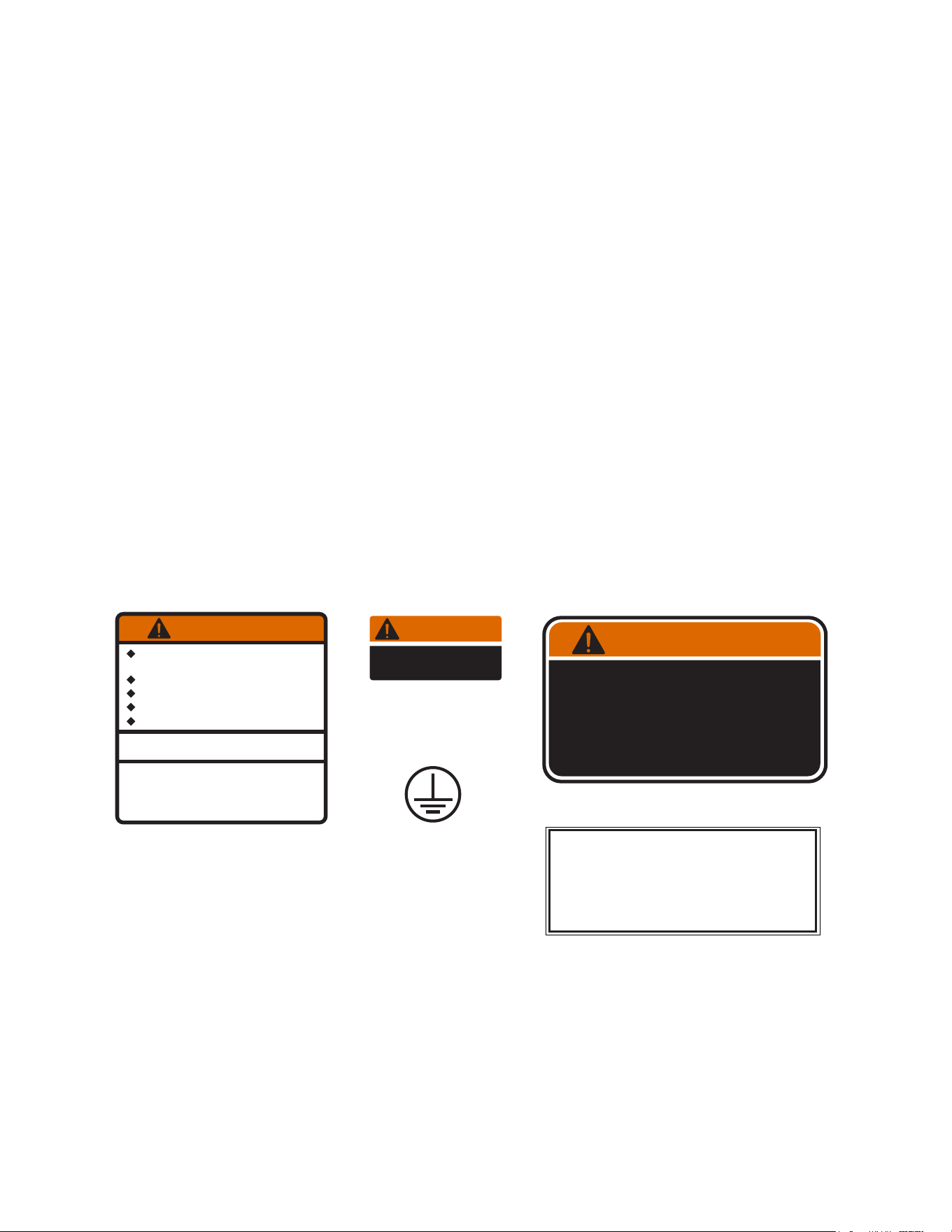
• Unplug the machine or turn off the main switch before servicing the interior components of the machine.
• Never operate the machine without water.
• Never touch brew module, spouts, and hot water dispense pipes. They are HOT and could cause burns.
• The machine must be operated with clean water. Make sure to use water filters and/or softeners
as needed.
Carefully read and follow all notices on the equipment and in this manual. They were written for your
protection. All notices are to be kept in good condition. Replace any unreadable or damaged labels.
USER NOTICES
WARNINGS
00656.0001
As directed in the International Plumbing Code of the
International Code Council and the Food Code
Manual of the Food and Drug Administration (FDA),
this equipment must be installed with adequate
backflow prevention to comply with federal, state
and local codes. For models installed outside the
U.S.A., you must comply with the applicable Plumb-
ing /Sanitation Code for your area.
00824.0002
35710.0000
WARNING
HOT
LIQUID
00986.0000
WARNING
FAILURE TO COMPLY RISKS EQUIPMENT
DAMAGE, FIRE OR SHOCK HAZARD.
READ THE ENTIRE
OPERATING MANUAL BEFORE
USING THIS PRODUCT
00986.0000M 10/14 ©1994 Bunn-O-Matic Corporation
Use only on a properly protected
circuit capable of the rated load.
Electrically ground the chassis.
Follow national/local electrical codes.
Do not use near combustibles.
Do not deform plug or cord.
37881.0000
To reduce the risk of electric shock,
do not remove or open cover.
No user-serviceable parts inside.
Authorized service personnel only.
Disconnect power before servicing.
WARNING
PRODUCT AND RECIPE SETUP ...........................................................................................................................34
Product Setup ......................................................................................................................................................34
Recipe Setup ........................................................................................................................................................36
Bean Hoppers Assignment .................................................................................................................................. 41
Bean Hoppers Setup ............................................................................................................................................42
Importing Custom Configuration Files ..................................................................................................................43
Grinder Calibration ...............................................................................................................................................46
Filling Reservoirs ..................................................................................................................................................50
Customer Interface ............................................................................................................................................... 51
SETUP MENU ......................................................................................................................................................... 52
Your Brand ...........................................................................................................................................................52
Screen Saver ....................................................................................................................................................53
OPERATION ............................................................................................................................................................54
ADA Interface .......................................................................................................................................................54
ACTIVE NOTICES ...................................................................................................................................................55
CONTENTS
continued from previous page

5
NORTH AMERICAN REQUIREMENTS
• This appliance must be installed in locations where it can be overseen by trained personnel.
• For proper operation, this appliance must be installed where the temperature is between 41°F to 95°F
(5°C to 35°C).
• Appliance shall not be tilted more than 10° for safe operation.
• An electrician must provide electrical service as specified in conformance with all local and
national codes.
• This appliance must not be cleaned by pressure washer.
• This appliance can be used by persons aged from 18 years and above if they have been given
supervision or instruction concerning use of the appliance in a safe way and if they understand
the hazards involved.
• Keep the appliance and its cord out of reach of children aged less than 18 years.
• Appliances can be used by persons 18 years and above with reduced physical, sensory or mental
capabilities or lack of experience and knowledge if they have been given supervision or instruction
concerning use of the appliance in a safe way and understand the hazards involved.
• Children under the age of 18 years should be supervised to ensure they do not play with the appliance.
• If the power cord is ever damaged, it must be replaced by the manufacturer or authorized service
personnel with a special cord available from the manufacturer or its authorized service personnel
in order to avoid a hazard.
• Machine must not be immersed for cleaning.
• Cleaning and user maintenance shall not be made by children unless they are older than 18 years
and supervised.
• This appliance is intended for commercial use in applications such as:
– staff kitchen areas in shops, offices and other working environments;
– by clients in hotel and motel lobbies and other similar types of environments;
• Access to the service areas permitted by Authorized Service personnel only.
CE REQUIREMENTS
• This appliance must be installed in locations where it can be overseen by trained personnel.
• For proper operation, this appliance must be installed where the temperature is between 5°C to 35°C.
• Appliance shall not be tilted more than 10° for safe operation.
• An electrician must provide electrical service as specified in conformance with all local and national codes.
• This appliance must not be cleaned by water jet.
• This appliance is not intended for use by persons (including children) with reduced physical, sensory
or mental capabilities, or lack of experience and knowledge, unless they have been given instructions
concerning use of this appliance by a person responsible for its safety.
• Children should be supervised to ensure they do not play with the appliance.
• If the power cord is ever damaged, it must be replaced by the manufacturer or authorized service
personnel with a special cord available from the manufacturer or its authorized service personnel in
order to avoid a hazard.
• Machine must not be immersed for cleaning.
• Machine rated IX P1.
6
Continued >
SITE REQUIREMENTS
SUPPORT
Plumbing
1. No Chlorine.
2. Water hardness 6 to 10 grains or less total hardness.
3. Water Filtration System:
Counter
• Machine must be level within 2˚ for proper
operation.
• Counter must be a sturdy, level surface able to
support 300 lbs.
• Recommend to have at least 2 people to place
machine on counter.
FOR INDOOR USE ONLY
WARNING
The brewer must be disconnected from the power
source until specified in Initial Setup. Refer to Data
Plate on the Brewer, and local/national electrical
codes to determine circuit requirements.
Brewer must be connected to a cold water system with operating pressure between 30 and 90 psi
(0.206 and 0.620 MPa) from a 0.5 inch or larger supply line. Install a regulator in the line when pressure is
greater than 90 psi (0.620 MPa) to reduce it to 50 psi (0.345 MPa).
NOTE: Bunn-O-Matic recommends .375 inch copper tubing for installations of less than 25 feet and
.375 inch for more than 25 feet from the 0.5 inch water supply line. A tight coil of copper tubing in the
water line will facilitate moving the brewer to clean the counter top. Bunn-O-Matic does not recommend
the use of a saddle valve to install the brewer. The size and shape of the hole made in the supply line by
this type of device may restrict water flow.
• 56000.0034 - SYSTEM, WEQ-35 (3).2L
• 56000.0126 - CARTRIDGE, WEQ-35 (3.4).2L
For best results include:
Water Treatment
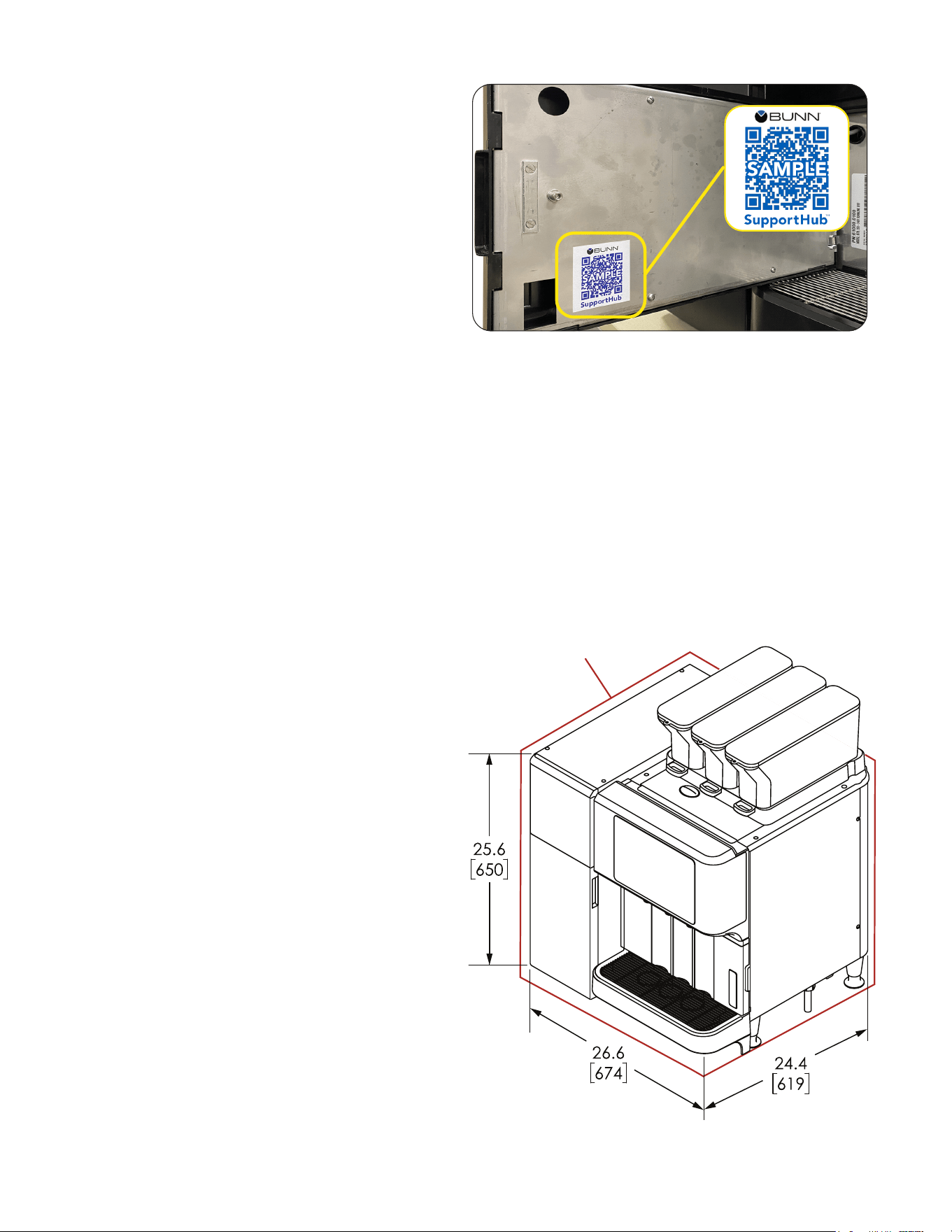
BUNN SupportHub provides easy access to
comprehensive information and resources tied to
the specific serial number for this product. Scan
the QR code with any smart device for access
to manuals, product information, training videos,
service support and other related information.
BUNN SupportHub
LEVEL COUNTER
(supports 300 lbs)
2 inch clearance
around machine
®
7
CAUTION: Improper electrical installation will damage electronic components.
1. An electrician must provide electrical service as specified.
2. Using a voltmeter, check the voltage and color coding of each conductor at the electrical source.
3. Connect the dispenser to the power source.
4. If plumbing is to be hooked up later be sure the dispenser is disconnected from the power source.
If plumbing has been hooked up, the dispenser is ready for Initial Fill & Heat.
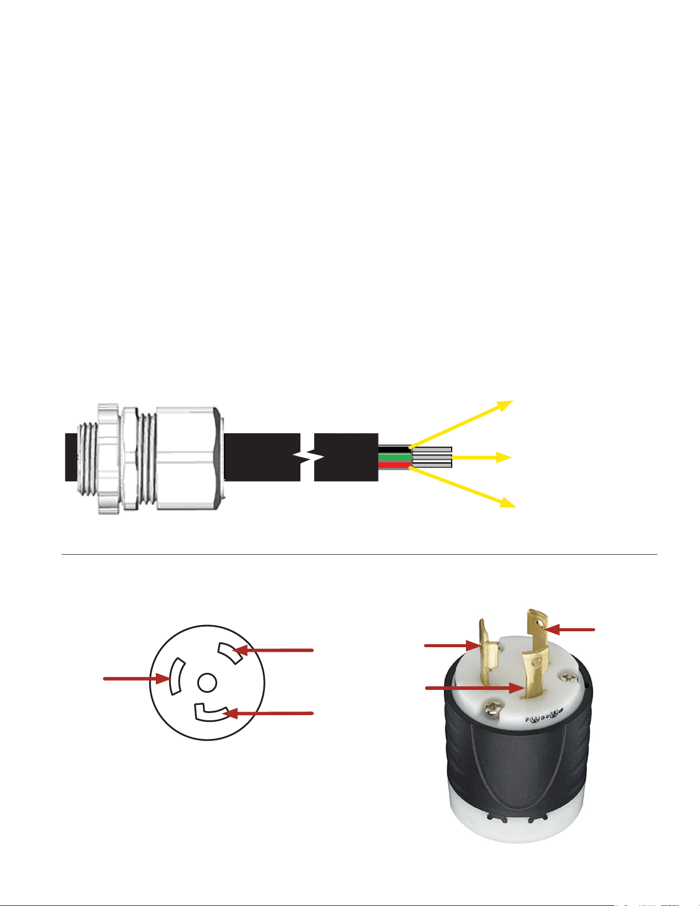
EXAMPLE
• 208/240VAC circuit (voltage range +5/-10%).
• Dedicated 30-amp circuit: cord cap, receptacle, and breaker
• Machine is supplied with a power cord (PN 46908.0002) AWG 10/3 30A/250V with Plug L1, L2, G.
NOTE: (N) no neutral wire/conductor used.
• Receptacle within 4.5 feet (1.4 meters) of the machine. (Note: the length of the power cord is
regulated by the machine’s UL certification; the length and type of cord cannot be substituted.)
• Machine total amp draw 24.0 amps at 208VAC, 22 amps at 240VAC.
• Determine the available on-site electrical service.
BLACK (L1)
GREEN (Ground)
RED or WHITE (L2)
Receptacle
Panel Strain Relief
Voltmeter
L1 - L2 = 208VAC
L1 - G = 120VAC
L2 - G = 120VAC
Power Cord, 10/3 30A/250V
NEMA L6-30P
NEMA L6-30R
Plug
BLACK
RED or
WHITE
GREEN
Electrical Configuration
INITIAL SETUP
Continued >
G
L1
L2
8
INITIAL SETUP
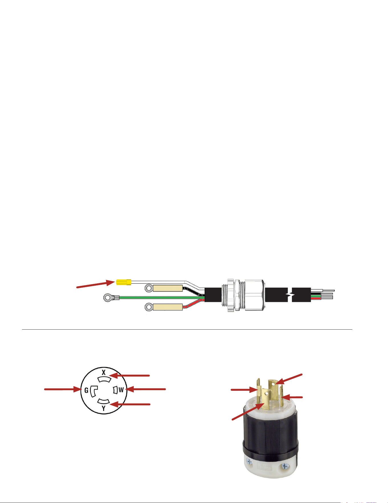
Optional Field Wiring
In the event the current location has an 1PH, 3 Wire plus Ground, 30 Amp electrical receptacle, the
machine power cord/plug (PN 46908.0002) will need to be removed and replaced with a power cord
and plug to match the current location receptacle configuration.
• 208/240VAC circuit (voltage range +5/-10%)
• Dedicated 30-amp circuit: cord cap, receptacle, and breaker
• Determine the available on-site electrical receptacle is 1PH, 2 Wire plus Ground or 1PH, 3 Wire plus Ground.
• Machine is supplied with a power cord (PN 46908.0002) AWG 10/3 30A/250V
with Plug L1, L2, G for use with 1PH, 2 Wire plus Ground receptacle.
NOTE: (N) no neutral wire/conductor used.
• If location electrical receptacle is a 1PH, 3 Wire plus Ground receptacle, see the attached Optional Field
Wiring decal on the machine and the following “Example” below.
• Remove supplied power cord and install AWG 10/4 30A/250V power cord with correct plug to match location
receptacle configuration.
NOTE: (N) Neutral wire/conductor (White Wire) from the power cord will need to be capped off in the
machine.
• Use the appropriate size of wire nut inside the machine over the power cord Neutral Wire (White) end and
push into the wire while twisting the nut clockwise. See Example.
• Receptacle within 4.5 feet (1.4 meters) of the machine.
NOTE: The length of the power cord is regulated by the machine’s UL certification.
• Machine total amp draw 24.0 amps at 208VAC
ELECTRICAL CONFIGURATION
Receptacle
L1 - L2 = 208VAC
L1 - N or G = 120VAC
L2 - N or G = 120VAC
NEMA L14-30R
Plug
L1 - Black
Wire
G - Green
Wire
L1
L2
N
G
L2 - Red
Wire
N - White Wire
(Not Used)
Power Cord, 10/4 - AWG
Wire Nut
Power Cord Plug End
Inside Machine
Continued >
EXAMPLE (Optional Field Wiring)
Voltmeter
9
INITIAL SETUP
Continued >
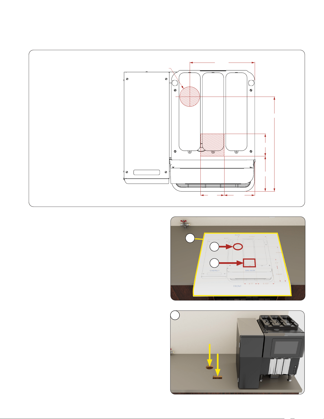
Drain and Waste Bin Setup
FRONT
CABINET BREWER
BACK
ø
4.0"
13.0625"
19.0625"
4.5"
7.0625"
6.125"4.75"
NOTE: The waste bin and drain line will require cutting a hole through the counter before the
machine can be installed. Refer to the diagram below for cut-out placement and measurements.
Countertop Template
Preparing Countertop
Tools Needed:
1. 3/4 inch drill bit
2. 4 inch hole bit
(PN 58837.0000)
1. Place the Countertop Template on surface you
plan to cut.
NOTE: Leave 2 inches of clearance around
machine.
2. Cut a 4 inch diameter circular hole in the rear of
the counter.
3. Cut a 4.5 inch square hole in the front of the
counter.
4. Remove Countertop Template.
5. Place machine over the two holes.
2
3
1
5
10
continued from previous page
INITIAL SETUP
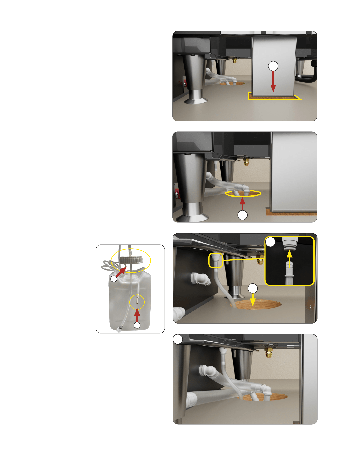
6. Center the Grounds Chute over the square hole
in front.
7. Place the 2 Reservoir Drain Hoses into the
circular hole in the back.
1. Remove the Cleaning
Tube from the container
by unscrewing the lid
and unraveling the tube.
6
7
Connect Hoses and Tubes
2. Attach the Push-to-Connect fitting end of the
Cleaner Tube into the white port under the
machine.
NOTE: Push the fitting up until snug.
3. Guide the end of the tube with the lid through
the circular hole.
NOTE: The tube can be pushed through
the circular hole from under the counter If
preferred instead.
3
4
Continued >
CLEANER TUBE
The 2.5 gallon container
has a Cleaning Tube
connected to it through
the lid (a) on one end and
a Push-to-Connect fitting
(b) at the other end.
a
b
2
Shown without Reservoir Hoses for clarity.
Shown with Reservoir
Hoses included.
11
continued from previous page
INITIAL SETUP
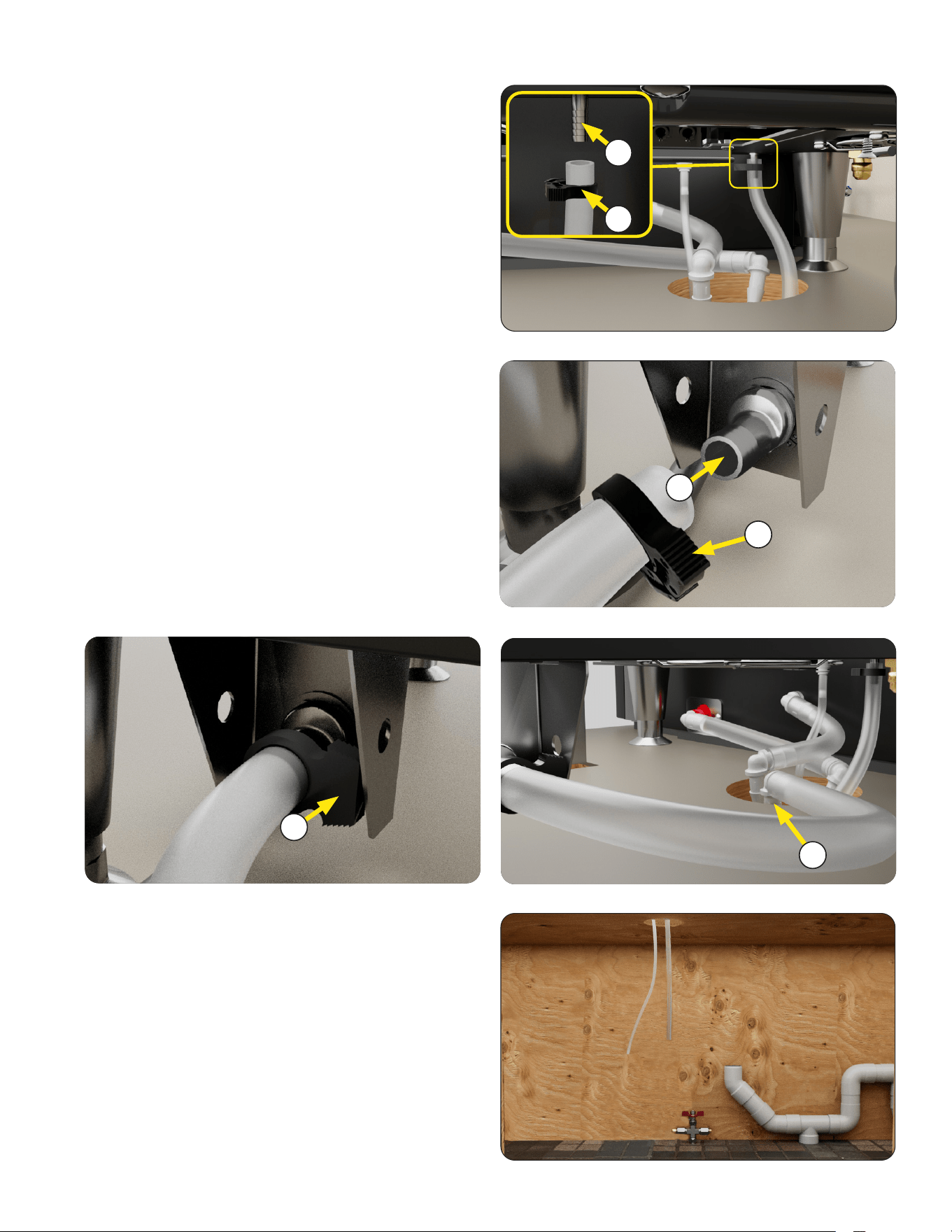
1. Attach C-Clamp to end of Tempering
Drain Hose.
2. Connect hose to barbed outlet under machine.
3 Tighten C-clamp around hose when secured
to outlet
1. Attach C-Clamp to end of Drip Tray Drain Hose.
2. Connect hose to outlet at the back of the
Drip Tray.
NOTE: The drain hose must be rated to
withstand temperatures of 200˚F (93.3˚C).
3. Tighten C-clamp around hose when secured
to outlet.
4. Place Cleaning Tube through circular hole
in counter.
Confirm Cleaning Tube and Tempering Drain Hose
are through the circular hole in the countertop.
2
1
TEMPERING DRAIN HOSE
DRIP TRAY DRAIN HOSE
HOSES AND TUBES THROUGH COUNTER
1
2
3
4
Continued >
12
INITIAL SETUP
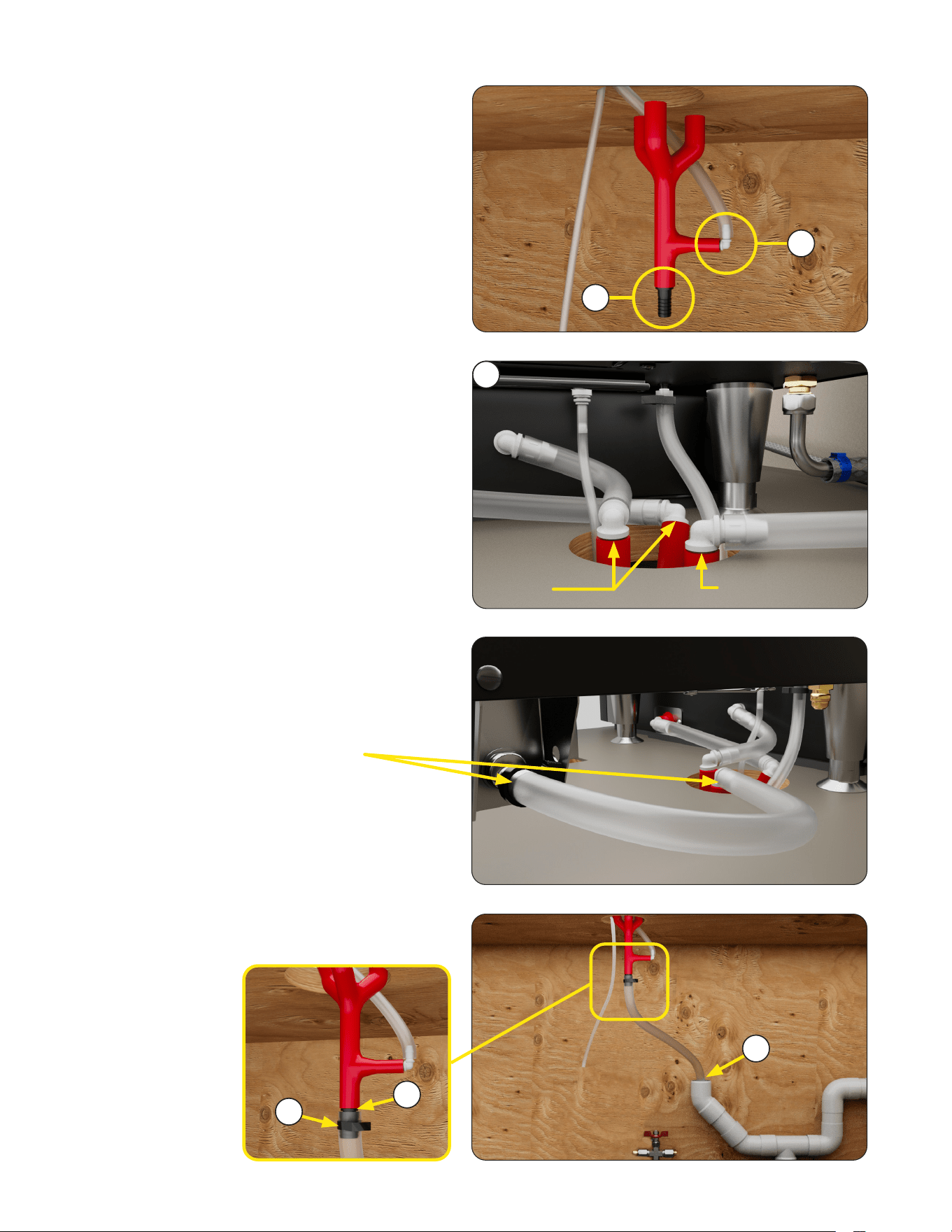
Install Undercounter Components
The Drain Hose Branch will combine the 4 drain
hoses into one drain source.
DRAIN HOSE BRANCH
1. Install Hose Barb into bottom of Drain
Hose Branch.
2. Connect the Tempering Drain Hose to lower
branch of the Drain Hose Branch at the elbow.
3. Push top of Drain Hose Branch through circular
hole in counter and connect the 2 Reservoir
Drain Hoses and the Drip Tray Hose to the 3
branches of the Drain Hose Branch.
4. Attach C-Clamp to the end of the Drain Hose.
5. Attach the end of
the hose with the
C-Clamp to the
barb at the bottom
of the Hose Branch.
Example: View from
the Drip Tray Hose
connections.
2
3
4
6
Reservoir
Hoses
Drip Tray Hose
6. Place other end
of hose inside
PVC drain.
1
5
13
INITIAL SETUP
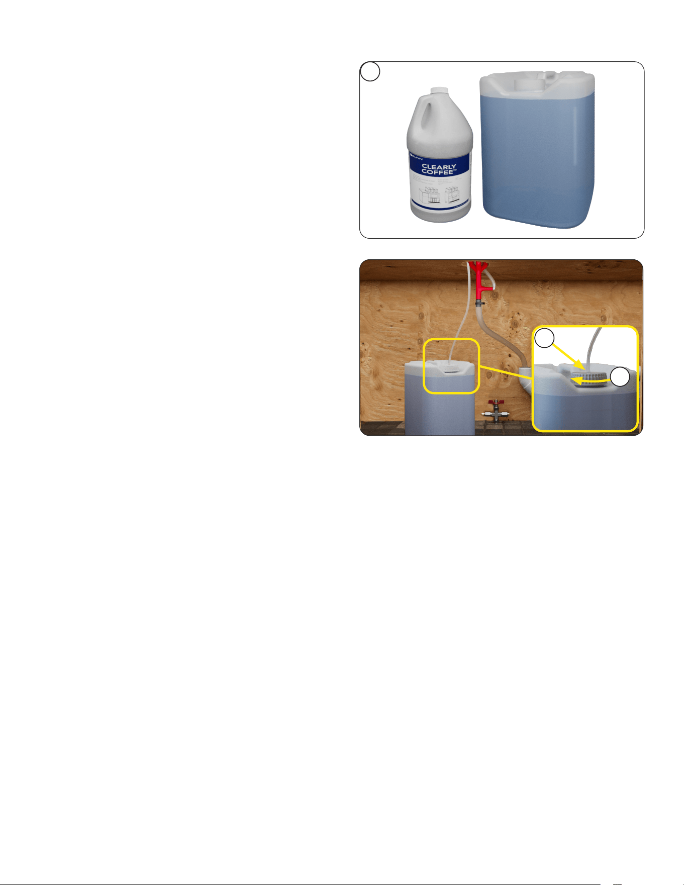
1
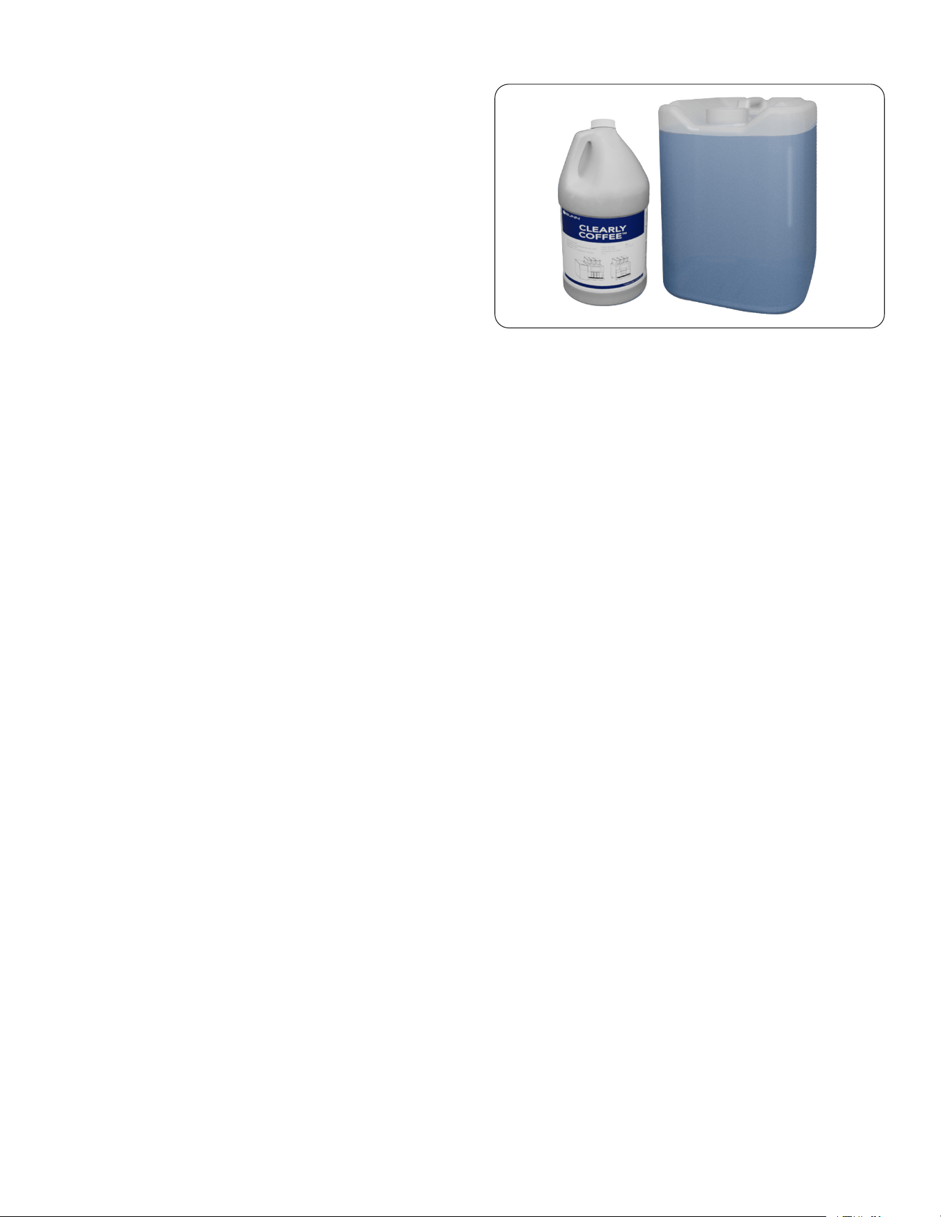
CLEANING LIQUID
Cleaning items included with machine:
• (4) Clearly Coffee Liquid Cleaner in 1 gallon
bottles (PN 58602.0002).
• (1) 2.5 gallon container with Cleaning Tube
connected through the lid on one end and a
Push-to-Connect fitting at the other end.
1. If the 2.5 gallon container is already connected
under the counter; remove the lid and pour
(2) 1 gallon bottles of cleaner into the container.
Then screw the lid back onto the container.
2. If the 2.5 gallon container has not been
connected yet, fill the container with (2) 1 gallon
bottles of cleaner.
Then place the container under the counter.
3. Screw the lid onto the container.
NOTE: The Cleaning Tube is 10 feet long.
Excess can be cut off, if preferred.
2
3
14
3
2
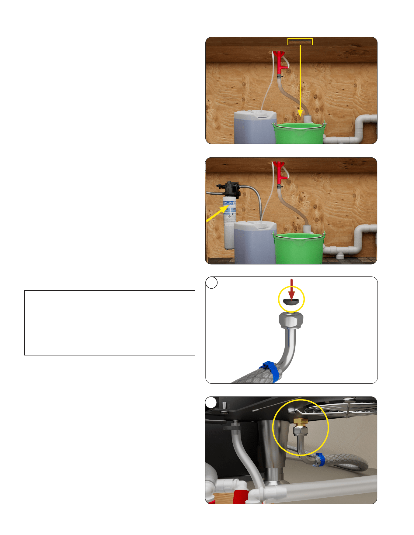
Plumbing Hook Up
1. Main water supply shut off valve should be
present between water supply and machine.
2. Place Nylon Gasket (find in separate bag) into
end of water line as shown. (PN 33149.0000)
3. Flush the water line and securely attach it to
the inlet fitting at the rear of the brewer.
4. Turn on the water supply and check for leaks.
As directed in the International Plumbing Code of the
International Code Council and the Food Code Manual of
the Food and Drug Administration (FDA), this equipment
must be installed with adequate back flow prevention to
comply with federal, state and local codes. For models
installed outside the U.S.A., you must comply with the
applicable Plumbing /Sanitation Code for your area.
The plumbing connection is a .375 inch male flare
fitting located on the lower, left, rear of the
machine as shown.
NOTE: Water pipe connections and fixtures directly
connected to a potable water supply shall be sized,
installed, and maintained in accordance with federal,
state, and local codes.
INITIAL SETUP
Place a 5 gallon bucket centered below the front,
square cutout in the countertop.
COFFEE GROUNDS BUCKET
WATER FILTRATION
continued from previous page
The recommended Water Filtration System should
be installed in the water line.
15
INITIAL SETUP
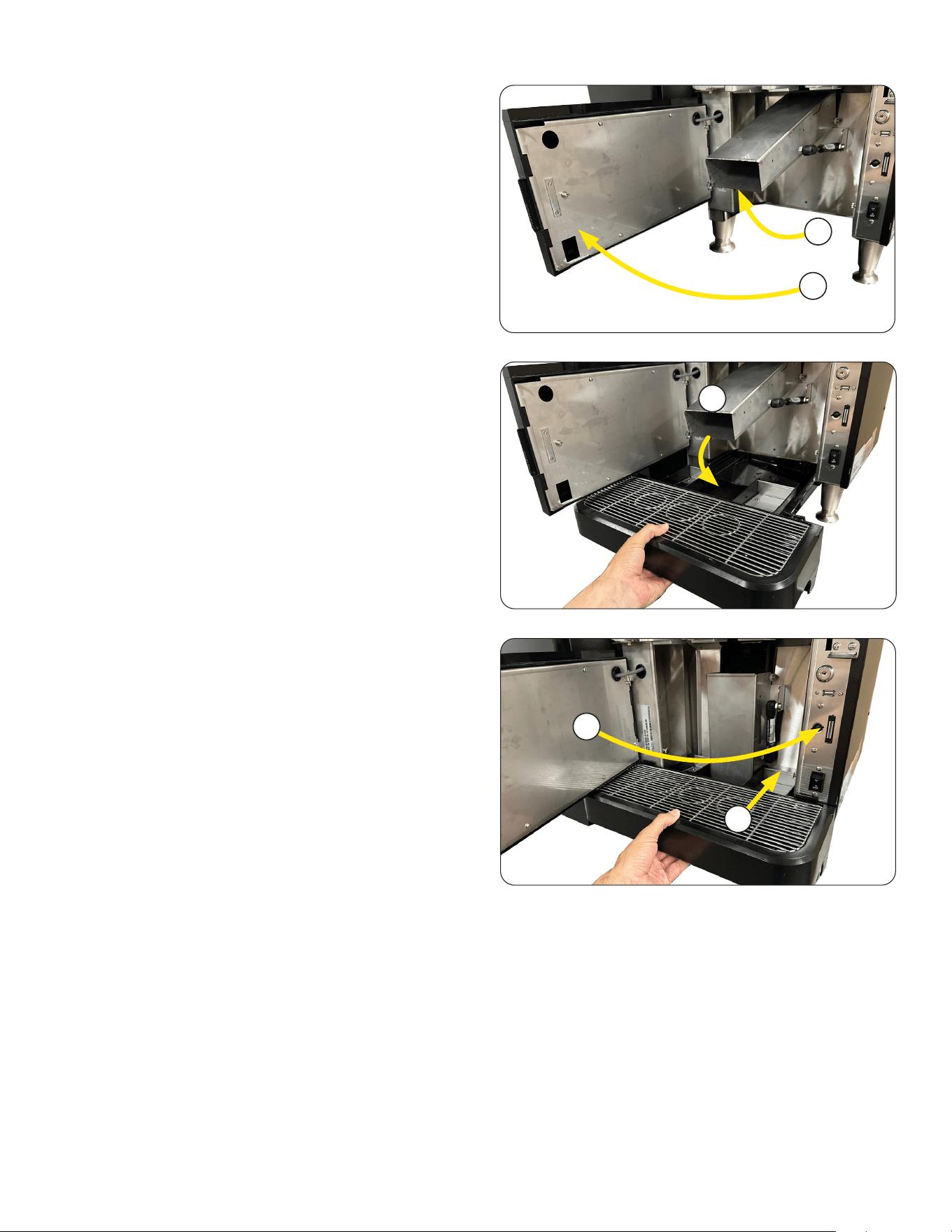
Drip Tray
1. Unpack the drip tray assembly.
2. Open the Lower Door.
3. Lift the Grounds Chute up.
4. Place the end of the grounds chute into the
opening in the drip tray.
5. Push drip tray back into machine.
6. Close the Lower Door.
Continued >
3
4
5
2
6
16
INITIAL SETUP
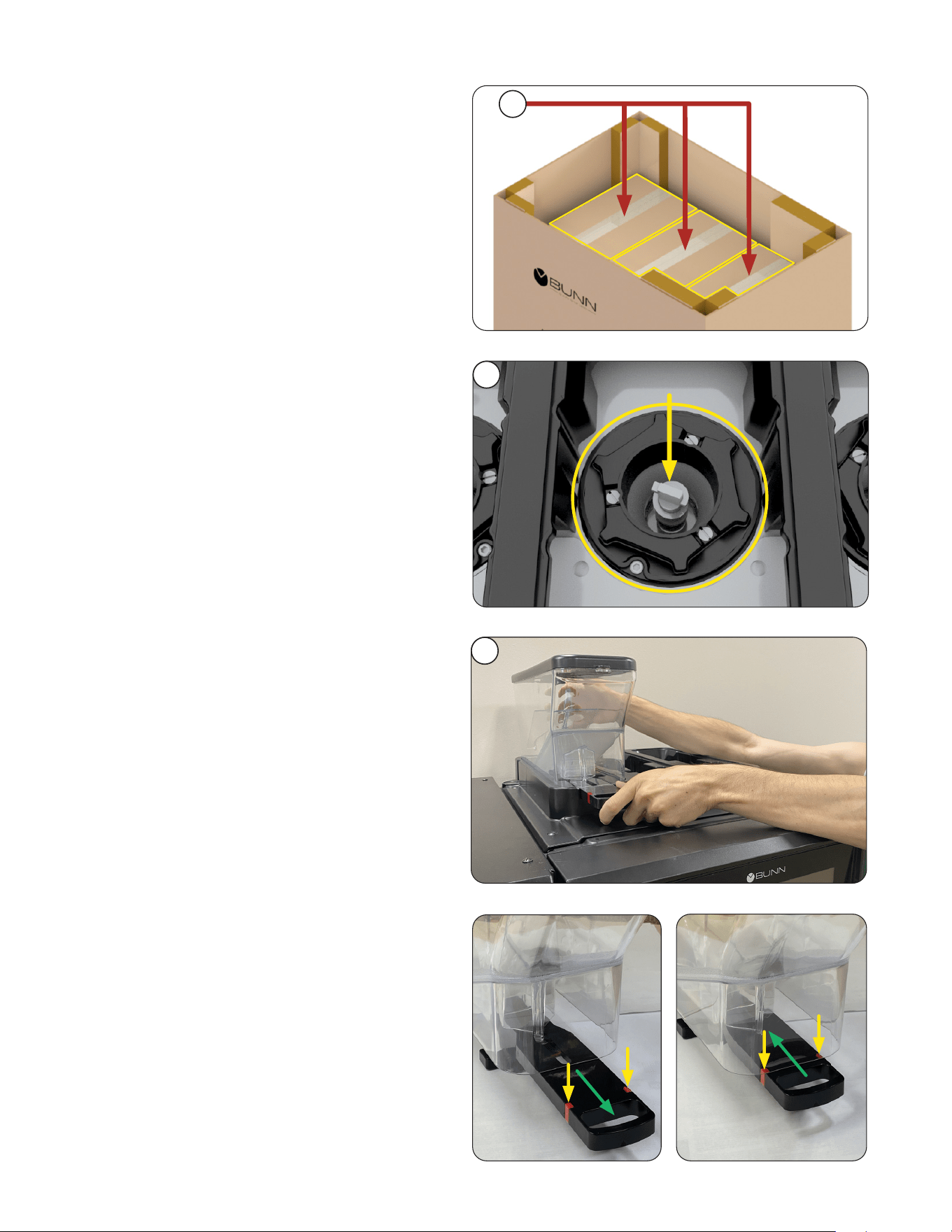
Bean Hoppers
Chutes Image
2. Prior to installing the bean hoppers, visually
verify that there is no debris or obstruction
blocking the bean chutes or bean
detection sensors.
NOTE: Each hopper holds approximately
3.7 lbs (1.68 kg).
3. Unpack and Install the bean hoppers in
any order.
Continued >
2
3
NOTE: The hoppers are boxed with the lids on.
NOTE: The gate on a hopper is closed when
the handle is pulled out and it stops beans from
flowing through to the grinder.
The gate is open when the handle is pushed in
and will let the beans through.
The red indicators will line-up with the front of the
hopper when pushed in completely.
Closed Open
1. Remove the three individual boxes containing
the bean hoppers.
1
17
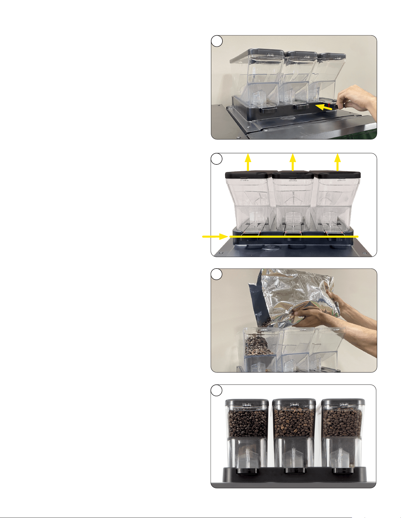
FILLING HOPPERS
NOTE: Hoppers should sit flat when in
place correctly.
7. Replace lids on hoppers.
INITIAL SETUP
4. When hoppers are in place, push gate handles
in to let beans flow down into grinders.
5. Remove lid(s).
6. Pour whole coffee beans in hopper(s).
NOTE: Apply "Roast Decals" if available.
Continued >
6
4
5
Left Center Right
7
continued from previous page
18
INITIAL SETUP
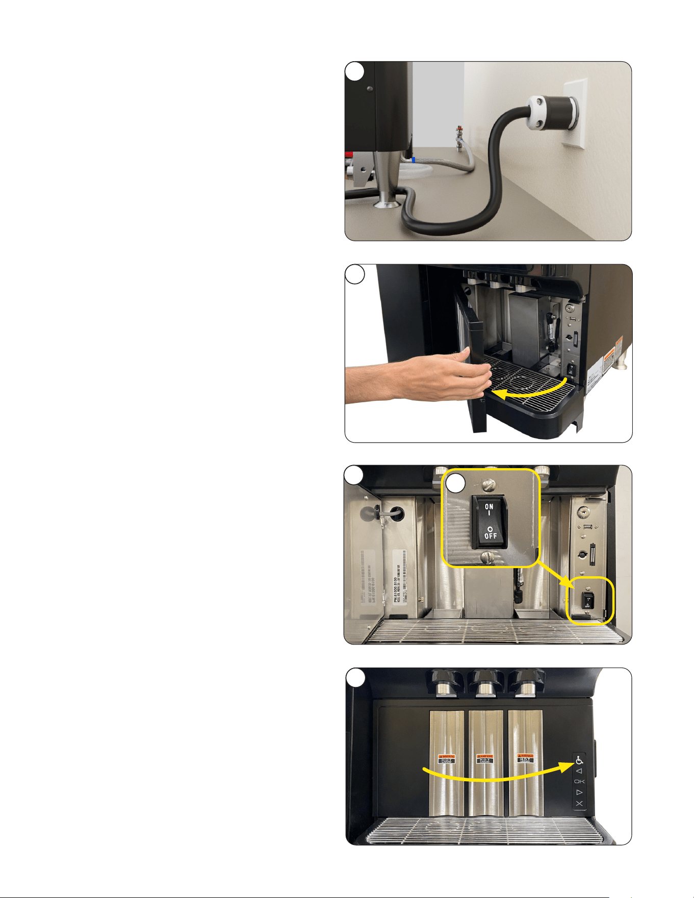
1. Plug-in to power supply.
2. Open Lower door.
3. Connect the unit to the power source (plug it in).
4. Turn the unit on by setting the power switch to
the ON position.
5. The door must be closed to begin the
initialization sequence, it may take 60-90
seconds, and the machine will reset in
preparation for user operation.
Continued >
1
2
3
5
4
Connect to Power
19
6. Once the initialization sequence is complete,
the User Interface screen will appear.
NOTE: Reminders for Daily and Weekly
cleaning are set for Monday at 1:00 AM as
a default.
If you want to change these parameters, go
to the Care and Cleaning section for steps
to revise.
INITIAL SETUP
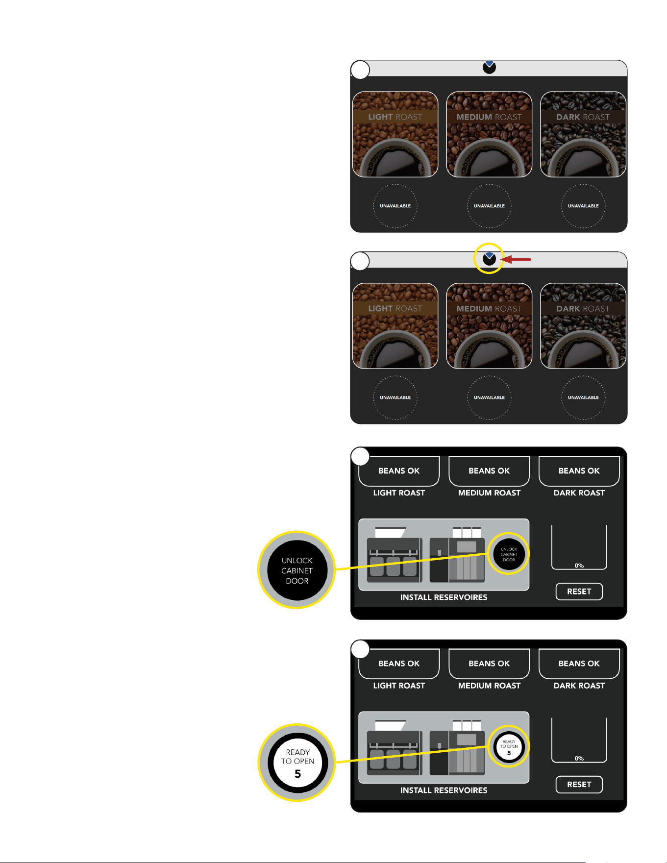
Cabinet Reservoirs
Once the initialization sequence is complete,
the USER INTERFACE screen will appear.
Press
2. Select Unlock Cabinet Door button to open
cabinet door.
Continued >
1
3
6
1. Press the BUNN Logo for a few seconds until
the Reservoirs screen appears.
2
3. A countdown of 5 seconds will start.
If not opened, the Unlock Cabinet Door button
will need to be pressed again.
33
continued from previous page
20
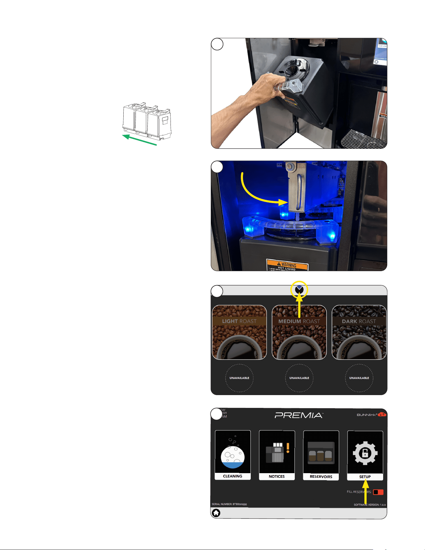
INITIAL SETUP
5. Locate the swing arm above the reservoirs and
use the handle to position it downwards over the
servers as shown.
5
4. Place all three reservoirs, one at a time, into the
cabinet with the reservoir handles facing out.
4
Waste Bin Setup
Use a waste bucket to collect used coffee grounds.
1
1. Press the BUNN Logo for a few seconds until
the Reservoirs screen appears.
NOTE: The position number of each
reservoir from front
to back is 3, 2, 1.
1
2
3
NOTE: When seated correctly, the reservoirs
will illuminate with blue lighting.
6. Close cabinet door.
BACK
FRONT
2. Select the SETUP icon.
2
continued from previous page
Continued >
21
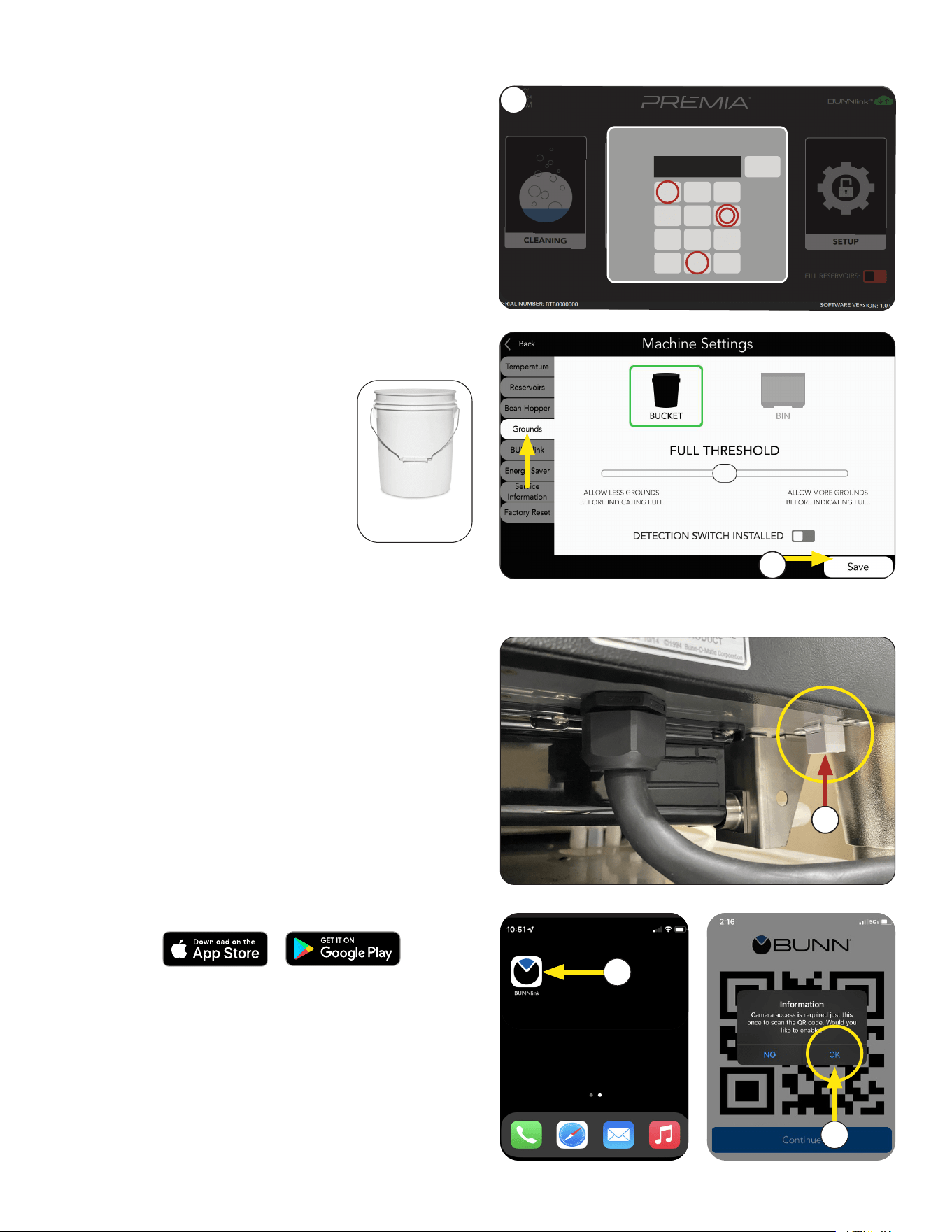
INITIAL SETUP
BUNNLINK ACTIVATION
4. Go to GROUNDS tab and select Bucket
as receptacle to collect grounds.
5. Select SAVE to complete.
5 Gallon
Bucket
NOTE: See "Adding a Waste
Bin Instructions" document
if you prefer to use a Waste
Bin instead.
3
PASSWORD
<
1 3
4 5 6
7 8
0
9
2
****
X
3. Enter passcode 6601.
5
1
These instructions are for connecting BUNNlink
from a compatible machine through WiFi using an
Ethernet connection.
Ethernet WI-FI Board Activation
1. If you are connecting to an Ethernet cable,
locate the Ethernet cable port.
If you are using WiFi only, proceed to next step.
2. Download the latest version of the BUNNlink
Mobile App to your smart phone through either
the Apple
®
App store for IOS or Google Play
®
store for Android.
3
4
NOTE: It will appear with the BUNN logo icon.
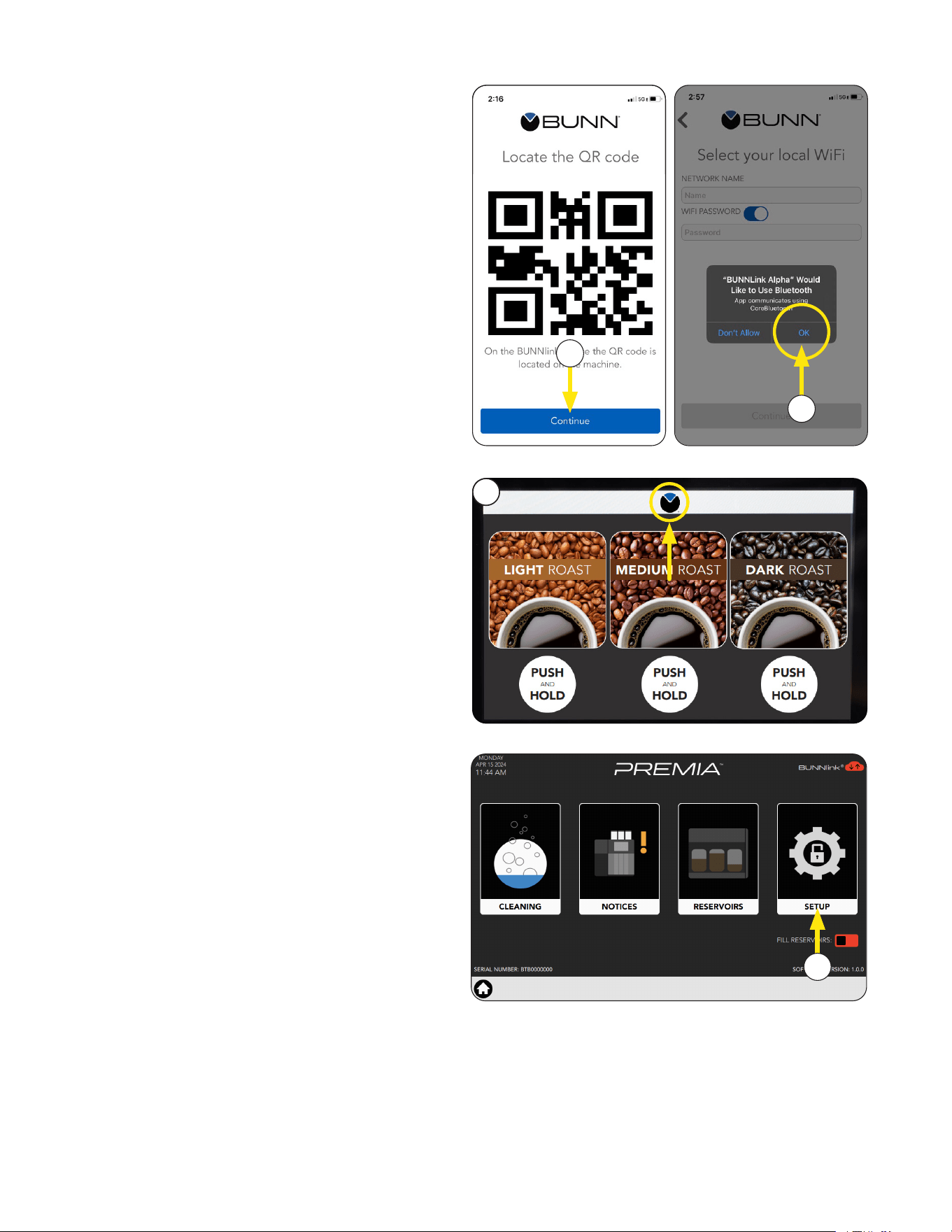
4. The app will ask you to enable the camera to
scan the QR code.
Select OK.
3. Open App when complete.
Continued >
continued from previous page
22
6. The app will ask permission to use Bluetooth.
Select OK.
5. This screen will display once accessed.
Press the CONTINUE button.
5
6
BUNNLINK ACTIVATION
continued from previous page
The location’s Wi-Fi network name and
password is required before BUNNlink
activation.
If you experience any issues with activation; contact
BUNN Tech Services at (800) 286-6070 or
email: b[email protected].
Steps to find out:
1. Press the BUNN Logo to open Service Access
screen.
1
2. Select Setup button for Premia machines.
2
Continued >
23
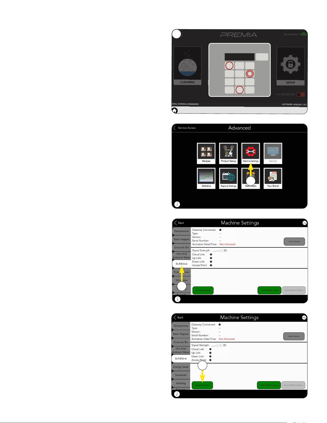
BUNNLINK ACTIVATION
3
PASSWORD
<
1 3
4 5 6
7 8
0
9
2
****
X
3. Enter passcode 6601.
4. Select Machine Settings.
4
5
5. Select BUNNlink Tab.
6. If not active, click on the Activate WiFi
Setup button.
6
Continued >
continued from previous page
24
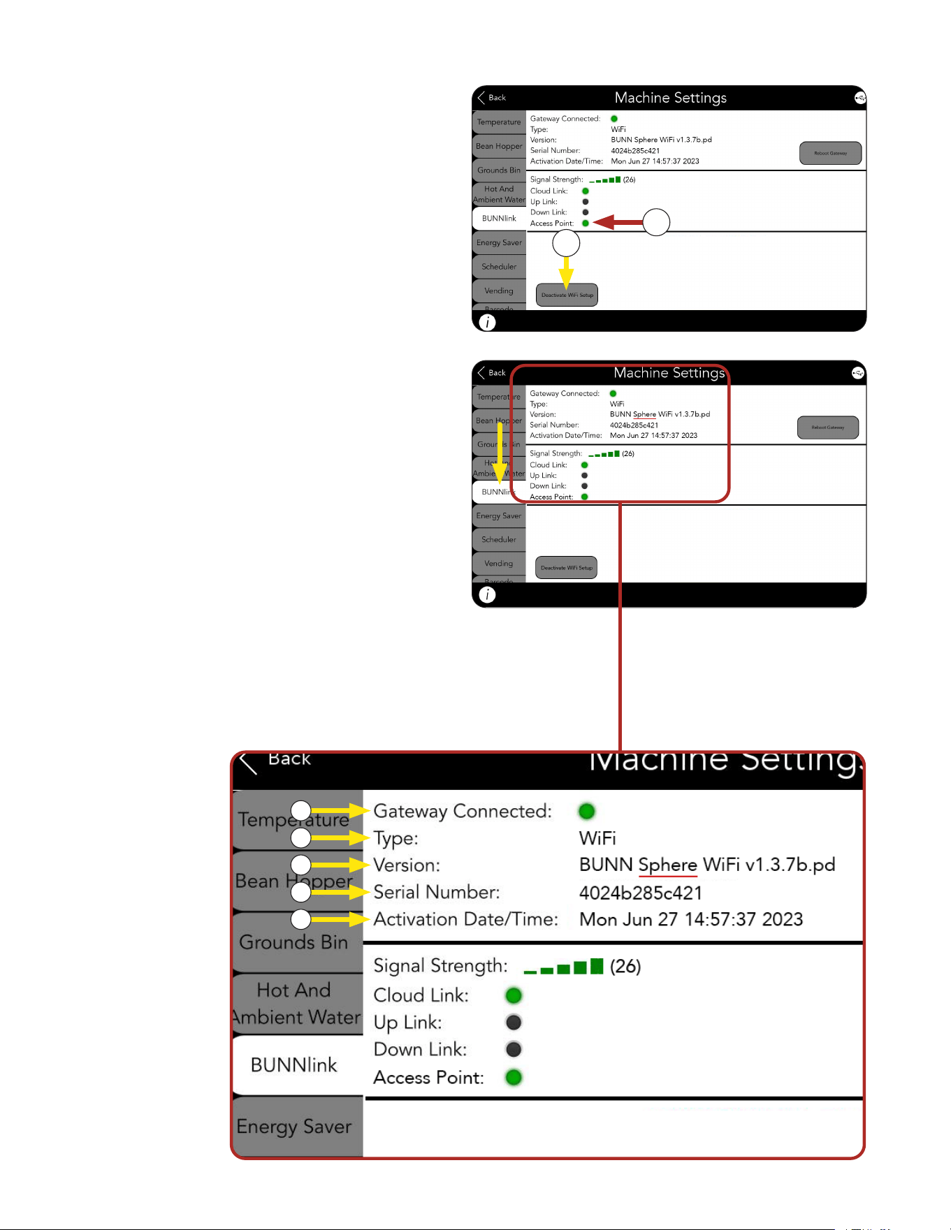
BUNNLINK ACTIVATION
a. Gateway Connected should be green to
indicate the machine and BUNNlink
gateway see each other.
b. Type of board shown as WiFi.
c. Sphere WiFi type should appear with/its
software version.
d. The Serial Number that appears on this
screen is the Mac Address for a Bunnlink
WiFi board.
BUNNlink Tab Information When Active
7. The button should change to grey and say
Deactivate WIFI Setup.
8. The Access Point dot should turn green.
NOTE: If Access Point is dark, power cycle the
machine for 5 minutes and start over.
7
8
b
a
c
d
NOTE: If white listing is needed, this is the
12-digit Mac Address that should be added
to the list.
e. Activation Date/Time when BUNNlink was
first enabled on the machine’s interface.
e
continued from previous page
Continued >
25
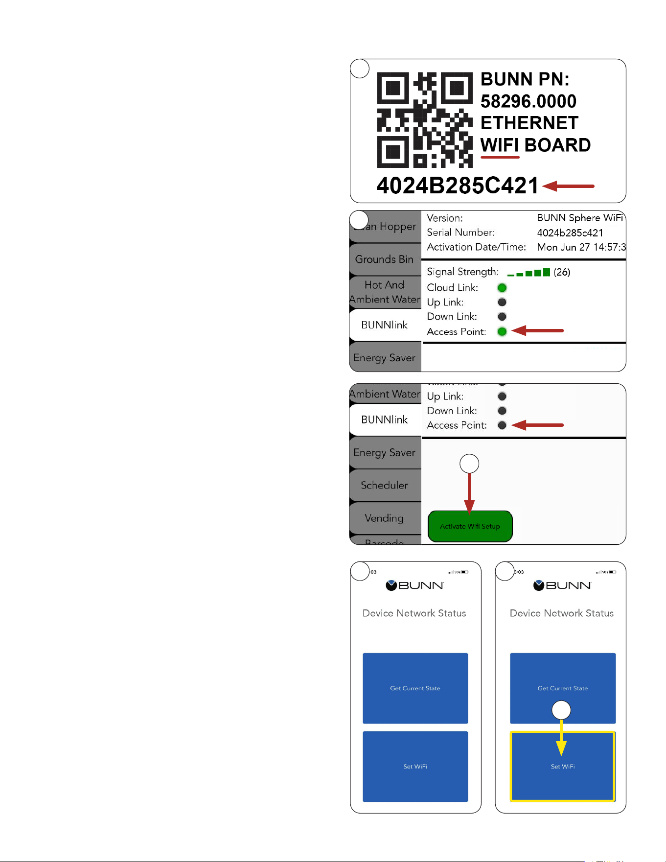
BUNNLINK ACTIVATION
10
9. Locate the QR Code decal either behind the
display or behind the door.
The decal should say it is for an Ethernet WiFi
Board and include a Serial Number with 12
alpha numeric characters underneath the
QR code image.
10. From the machine, go to the BUNNlink tab.
The Access Point should be green.
Proceed to step 12.
9
NOTE: The Serial Number that appears on
the decal should match the one on the screen
example in Step 8d.
NOTE: New kits will have a decal behind the
board, on the anti-static packaging, plus a spare
decal to stick on the machine when replacing or
installing a board.
11. If the Access Point is not green, click on the
Activate WiFi button.
When Access Point is green, proceed to step 12.
12. Scan the QR code using the BUNNlink Mobile App.
NOTE: It may take a couple of attempts.
Sometimes pulling back away from the image
while scanning works better than trying to get
the camera too close.
If you can’t scan the QR code, contact
[email protected] or 217-331-8428.
Leave a message if necessary. Your call will
be returned.
13. Connect to the WIFI Board. After a successful
QR Code scan, two buttons will appear on the
mobile app – Get Current State and Set WiFi
on the Device Network Status screen.
12
14
14. On the mobile app, click on Set WiFi.
13
11
Continued >
continued from previous page
26
17. Click Continue.
NOTE: If it fails, see Troubleshooting section.
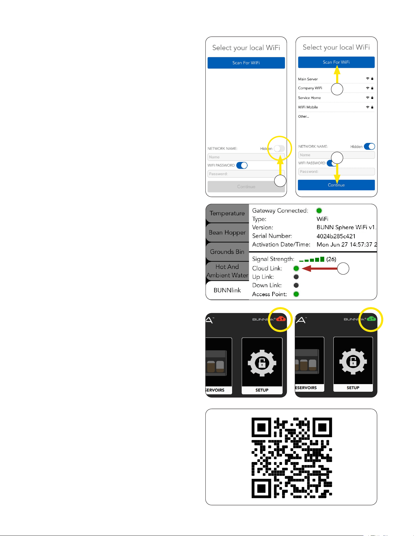
18. If successful, Cloud Link will turn green and
become steady, signal strength will show
green bars.
YOUR CONNECTION IS NOW COMPLETE.
18
15
16
17
15. If you are connecting to a hidden network,
enable the Hidden toggle located on the app
before Scanning for WiFi.
If successful, a list of available networks
will appear.
16. If you have the location’s network name and
password, you may enter it manually, or select
the name from the list of available networks and
enter the password.
Scan to register your machine on BUNNlink
®
for
Customer Care Alerts, reports and further support.
Please provide this QR code to the customer or
manager of the site.
Product Registration
continued from previous page
BUNNLINK ACTIVATION
NOTE: BUNNlink connection is also shown with
the color change of the cloud icon in the upper
right corner of the Service Access screen from
Red to Green.
27
6
CARE AND CLEANING
Continued >
Accessing Care and Cleaning
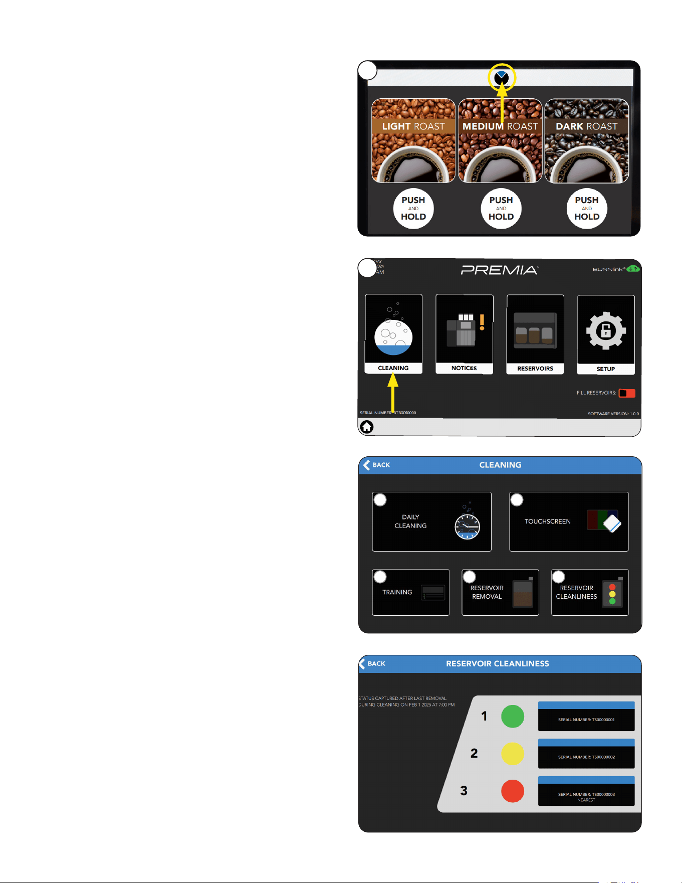
2. Select the Cleaning icon.
1. Press the BUNN logo for a few
seconds until SERVICE ACCESS appears
on the display.
2
1
a
b
c
a. Daily/Weekly Cleaning: Select this icon
to begin a cleaning cycle.
b. Touchscreen: Select this icon to deactivate
the display for a brief period to allow for
touchscreen cleaning.
c. Training: Select this icon to view the weekly
cleaning steps for training purposes.
d. Reservoir Removal: Select this icon to unlock
the cabinet for reservoir removal.
e. Reservoir Cleanliness: Select this icon to
view the status of each reservoir. The
status is color coded to indicate how well the
reservoirs have been manually cleaned.
• Green = Clean
• Yellow = Moderately Clean
• Red = Cleaning Recommended
Use the Reservoir Removal
icon (d) to remove the reservoirs
and perform a manual cleaning.
CLEANING MENU
d
e
28
CARE AND CLEANING
Continued >
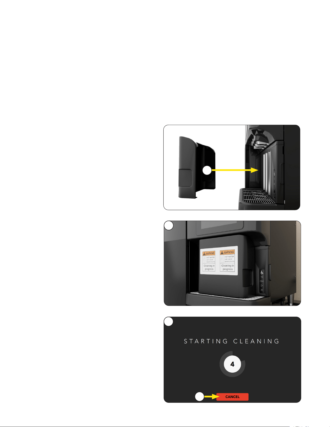
How to Begin a Cleaning Cycle
1. Place the Cleaning Shield on the drip tray
and over the dispense area to initiate a
cleaning cycle.
2. When placed properly, the decals on the
cleaning shield will face the operator.
3. If the machine is ready to begin the cleaning
without further interaction, the "Start Cleaning"
countdown will appear.
4. Follow the prompts on the display to complete
the cleaning cycle. Do not remove the Cleaning
Shield until the process is complete.
NOTE: While cleaning is in process, you can
touch the display to see a status bar with details
about the cleaning cycle. Use the Cancel button
to stop the cleaning cycle.
You can initiate a cleaning cycle through the
Cleaning menu (see section Accessing Care
and Cleaning). If Cleaning is already scheduled
and you're operating within the time frame of the
schedule, then you can simply place the cleaning
shield on the machine to begin cleaning:
1
2
3
4
• Do not use any abrasive materials.
• Use a soft, dry cloth to wipe down the exterior surfaces of the dispenser to maintain the luster of the
stainless steel finish.
• Wash the stainless steel interior surfaces of the dispenser with warm, soapy water. Rinse with warm,
clear water. If the water is hard, wipe the dispenser dry with a soft cloth to prevent spotting.
• Use cleaning cloth (provided) to clean the acrylic door panel.
• Use only mild, non-abrasive and citrus-free soaps and detergents for cleaning surfaces.
Interior and Exterior Surfaces
BEFORE STARTING
29
CARE AND CLEANING
Continued >
Refilling the Cleaning System
The machine will automatically refill the system
with cleaner until the external container is empty.
• Once empty, you will have an estimated 3 days
until the machine will ask you at the end of a
cleaning cycle to refill the system.
• If the system is not refilled with cleaner, the
machine will allow you to continue operation for
the next 3 cleaning cycles before locking out.
• The type of liquid cleaner used during the cycle
is also important, because the system will only
recognize an approved type. If an incorrect
cleaner is used during the refill process, the
machine will notify you to change cleaner.
• NOTE: See installation section for details on
Liquid Cleaner.
30
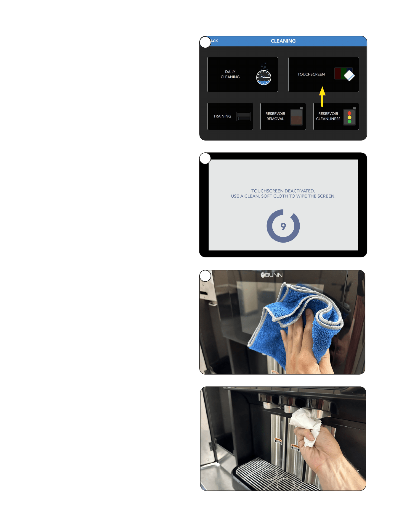
1. Select the Touchscreen tab to start a countdown
screen to temporarily shut off the sensitivity of
the screen so that it can be cleaned.
2. The screen will stay inactive for 10 seconds.
3. Clean the touchscreen using cloth provided
in the cleaning products. The surface should
be free of debris and dry to the touch once
completed.
Touch Screen
1
– As Needed
2
3
Front Panel
Clean the dispense area using a soft, dry cloth.
– As Needed
CARE AND CLEANING
31
CARE AND CLEANING
Continued >
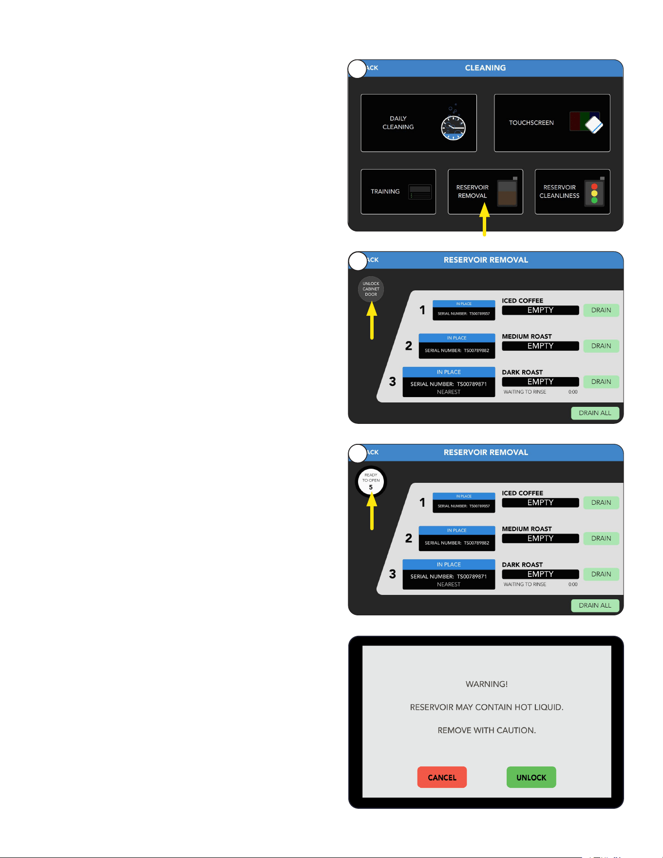
Reservoir Removal
– As Needed
1. Select the Reservoir Removal button.
Reservoir cleaning is included in scheduled Weekly
cleaning, but if access to reservoirs at other times is
needed, follow these steps.
2. Select Unlock Cabinet Door button to access
reservoirs.
1
2
3. A countdown of 5 seconds will start.
If not opened, the Unlock Cabinet Door button
will need to be pressed again.
3
CAUTION: If there is liquid in a reservoir; the
option to drain each or all reservoirs can done
by pressing the Drain buttons.
A countdown timer will show progress of draining.
NOTE: If reservoirs are removed without draining,
then a warning screen will show to remove with
caution because they may contain hot liquid.
32
CARE AND CLEANING
Continued >
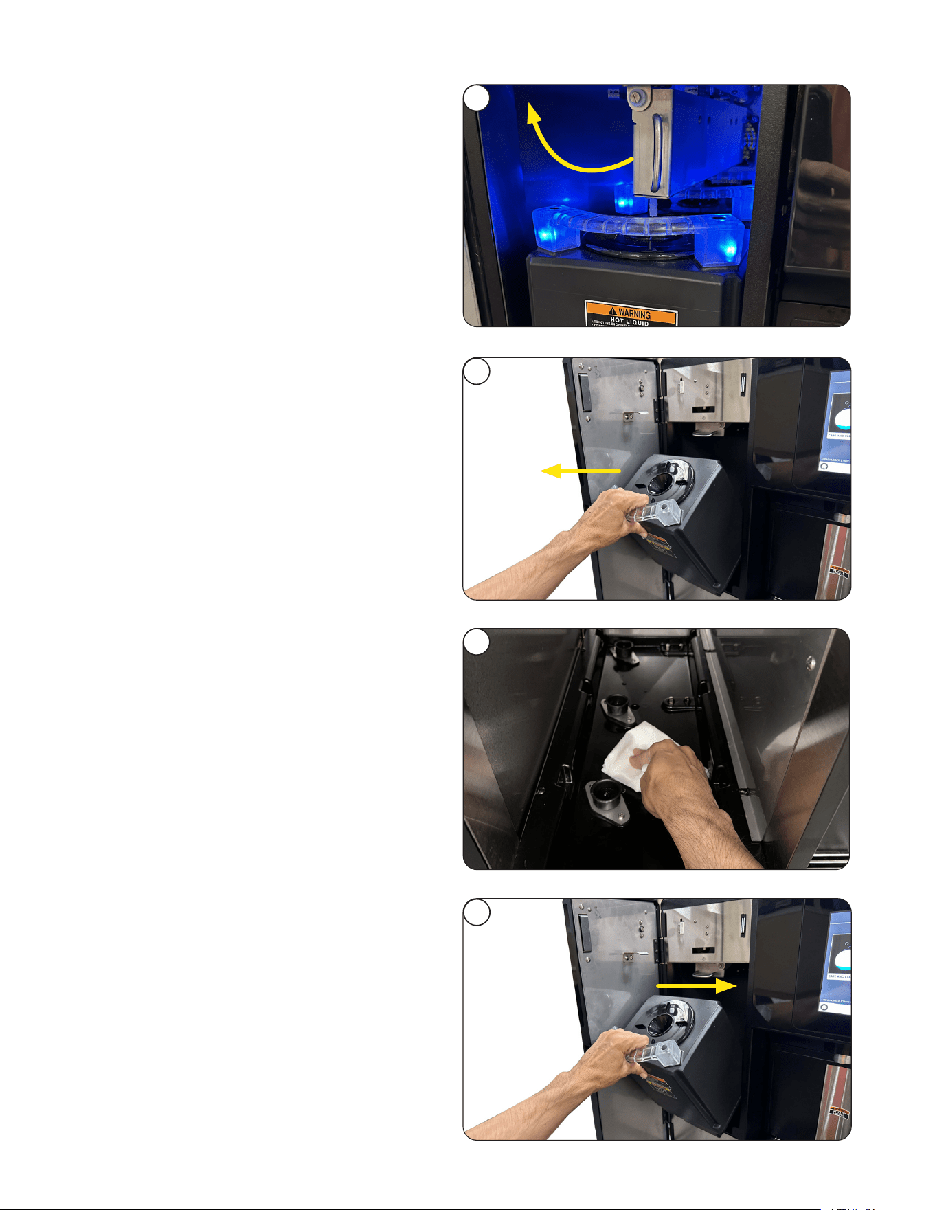
4
5
7
4. Locate the swing arm above the reservoirs and
use the handle to pull it up over the reservoirs.
5. Remove the 3 reservoirs.
6. Clean the inside of the cabinet deck area
using a soft, dry cloth.
6
7. Place all three reservoirs in the cabinet with the
reservoir handles facing out.
NOTE: When seated correctly, the reservoirs will
illuminate with blue lighting.
continued from previous page
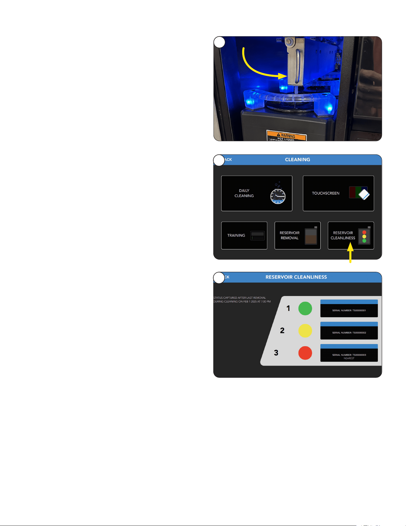
33
CARE AND CLEANING
8. Locate the swing arm above the reservoirs and
use the handle to pull it down over the reservoirs.
9. Close cabinet door.
8
continued from previous page
Reservoir Cleanliness
2. Dot color represents level of cleanliness for
each reservoir.
1
2
Reservoir Cleanliness: Select this icon to view the
status of each reservoir. The status is color coded
to indicate how well the reservoirs have been
manually cleaned.
• Green = Clean
• Yellow = Moderately Clean
• Red = Cleaning Recommended
NOTE: Use the Reservoir Removal
icon to remove the reservoirs and perform
a manual cleaning.
34
PRODUCT AND RECIPE SETUP
2
1
3
PASSWORD
<
1 3
4 5 6
7 8
0
9
2
****
X
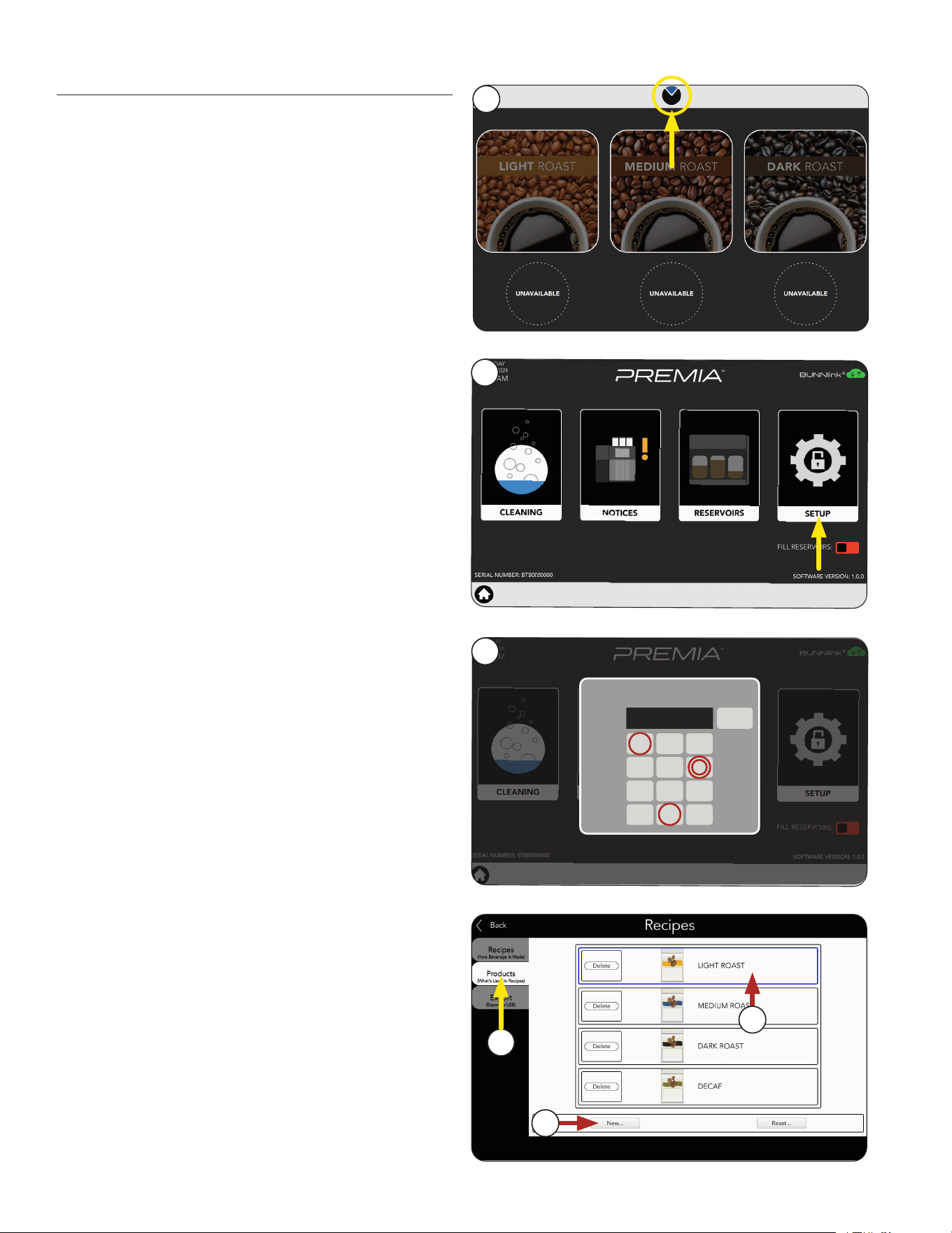
First, setup a coffee Product.
Product Setup
How to Access:
1. Touch and hold the BUNN logo for a few
seconds until the SERVICE ACCESS
screen appears.
2. Select the SETUP icon.
3. Enter passcode 6601.
If you have a custom configuration saved on a USB
stick, skip to "Importing Custom Configuration Files"
on page 40 for more information.
4
4. Select the PRODUCTS tab.
6. Or, create a new product by selecting the
New button.
5. Choose an existing product to edit.
For this example, we will select "Light Roast".
6
5
NOTE: If you decide not to use an available
product on the screen, then you will need
to create new recipe(s) before they can be
assigned to a hopper.
Continued >
35
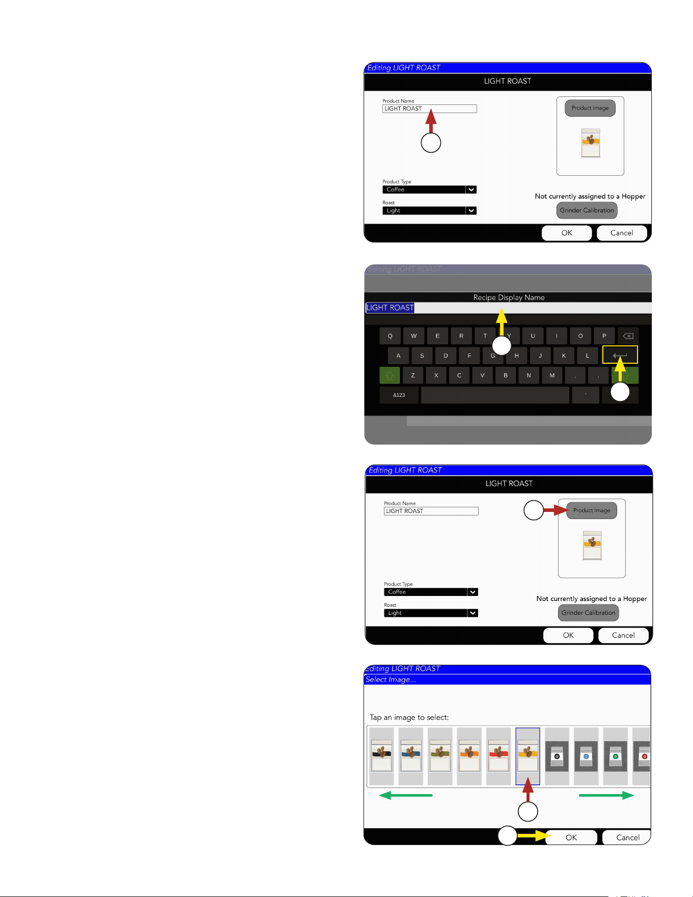
RECIPE AND PRODUCT SETUP
7. Choose the Product Name field if you want to
change the current name.
7
8. The Product Name screen will appear.
Click in the text field and type a new
Product name, if preferred.
9. Press the Return key to complete.
10. Choose the Product Image button if you want to
change the current image.
10
8
9
11. Next, scroll side-to-side to see available images.
Select the chosen Product Image.
11
12
12. If a new image is chosen, press OK.
continued from previous page
Continued >
36
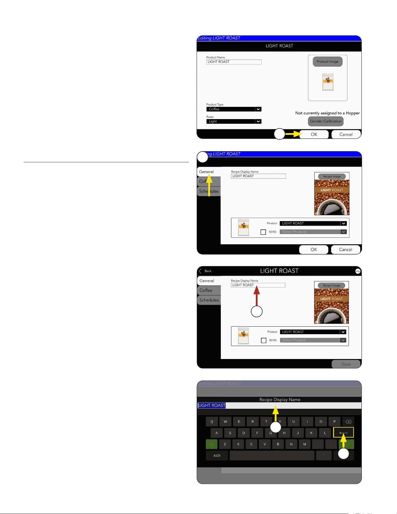
RECIPE AND PRODUCT SETUP
Recipe Setup
13. Press OK to complete this Product creation.
13
1. Choose the GENERAL tab.
2. The coffee product name can be edited by
pressing on the text field.
1
2
3. The Recipe Display Name screen will appear
Click in the text field and type a new
recipe name, if preferred.
3
4
4. Press the Return key to complete.
continued from previous page
Continued >
37
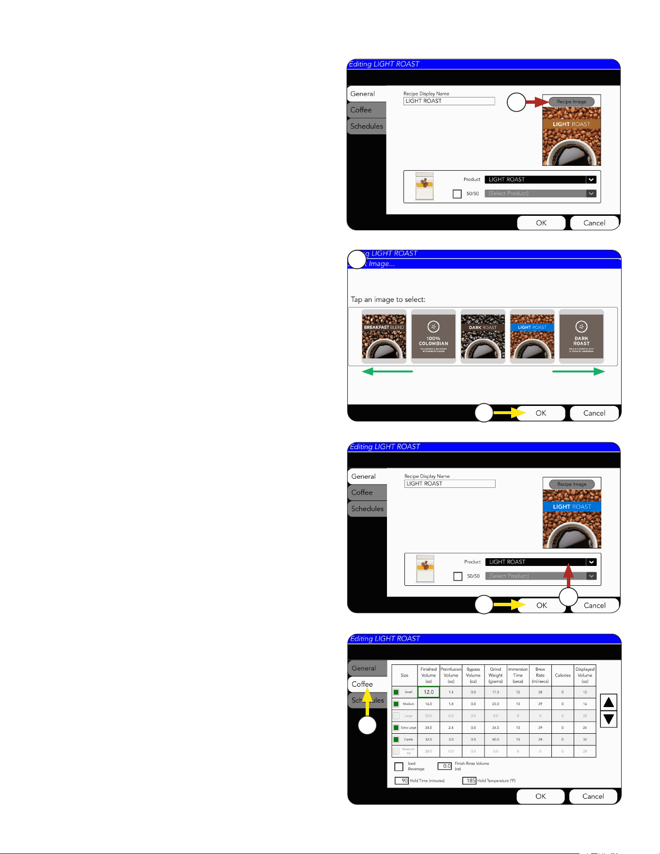
RECIPE AND PRODUCT SETUP
5. Next, the Recipe Image can be changed,
if preferred.
5
Continued >
10. Choose the Coffee tab to edit the recipe.
10
6
6. By swiping side-to-side, you can view the
icon library.
7
8. Use the drop down menu to select the
preferred coffee Product. This will be the
coffee bean that is used for this recipe.
8
9
7. Select the image, and press OK.
9. Select OK button when complete.
continued from previous page
38
RECIPE AND PRODUCT SETUP
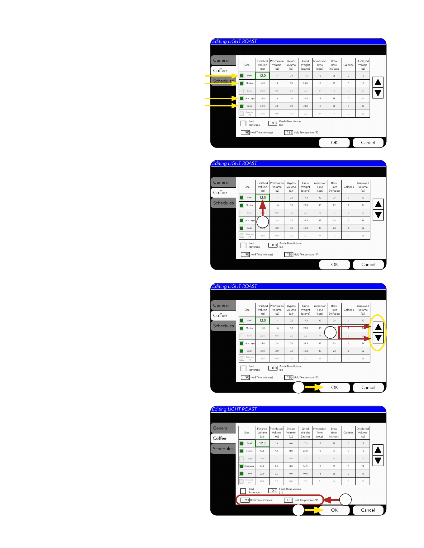
NOTE: Each size with a green box
is enabled.
Coffee Recipes can be edited from this screen by
clicking any of the numbers in the table cells.
2. For this example the Small Volume is being
revised as shown by the green border.
4. Press OK if changes are made.
3. The arrows on the right side of the screen can
increase or decrease the selected number by
decimal points. Example: 8.0 to 8.1, 8.2. 8.3, etc.
2
3
4
6. Press OK if changes are made.
5. You can also adjust the hold time and hold
temperature for the recipe.
6
5
Continued >
continued from previous page
39
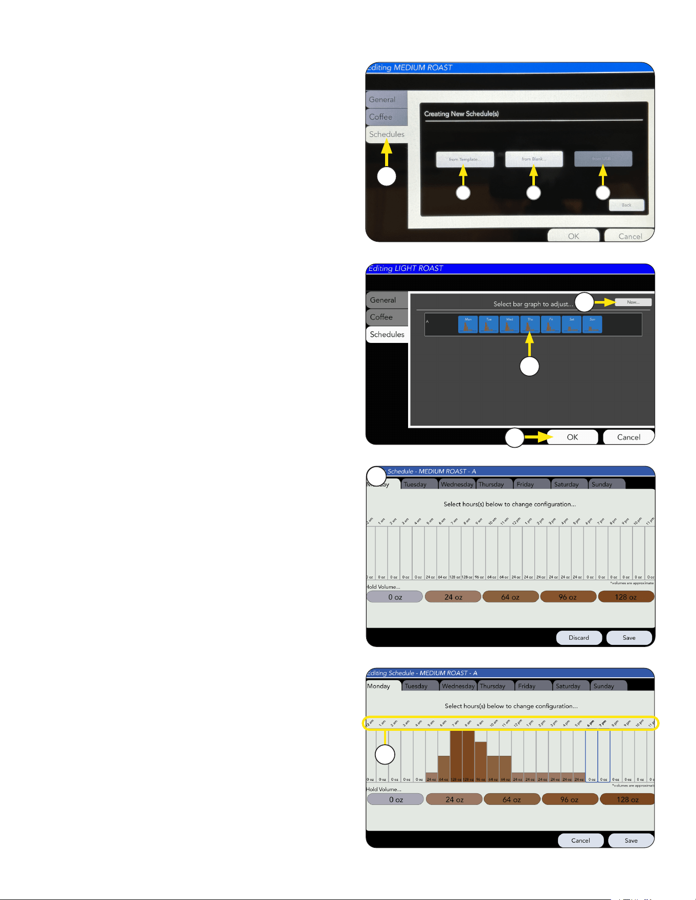
1. Choose the Schedules tab to edit the recipe
hold volumes for each hour/day.
RECIPE AND PRODUCT SETUP
Select an option:
a. Use an existing template to edit by selecting
"from Template" to open schedule window.
b. Create a new schedule by pressing "from Blank"
button.
c. Upload an existing schedule from a saved file
using a USB stick.
See "Importing Custom Configuration Files" for
more information.
1
Continued >
a
b
c
continued from previous page
6. To adjust the hold volume, Select the hours(s)
on the screen to change the configuration.
6
5. The Schedules Tab allows you to adjust hold
volume for different times of each day. This
is useful when trying to conserve energy and
waste during down times as well as keep up with
high volume peak times.
4. Select OK if changes are made.
2. Select Schedule window to see more daily
adjustments.
3. Select New button to create a new schedule.
4
2
3
5
40
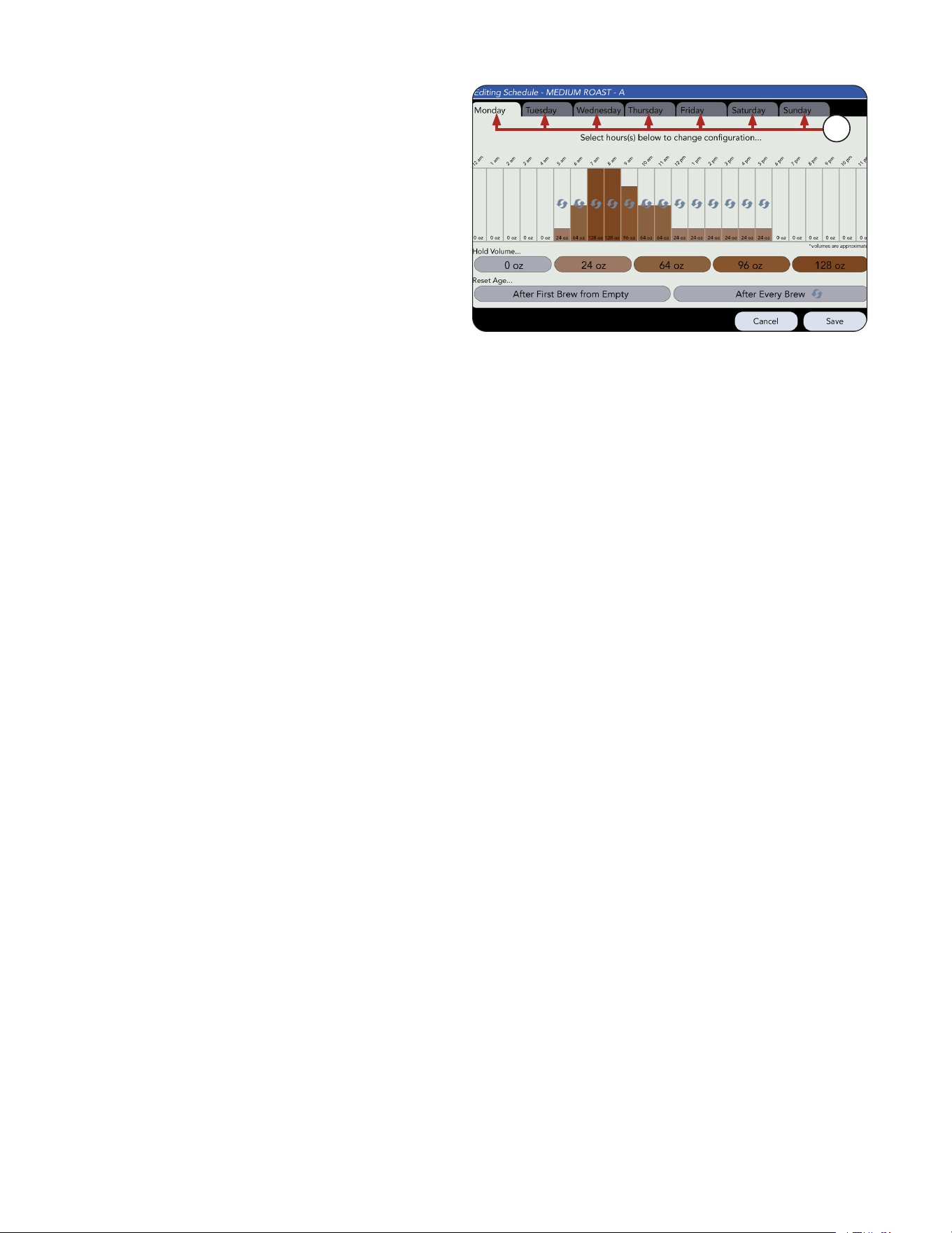
7. Select another tab (day) to make further
adjustments and select SAVE when finished.
RECIPE AND PRODUCT SETUP
7
continued from previous page
41
RECIPE AND PRODUCT SETUP
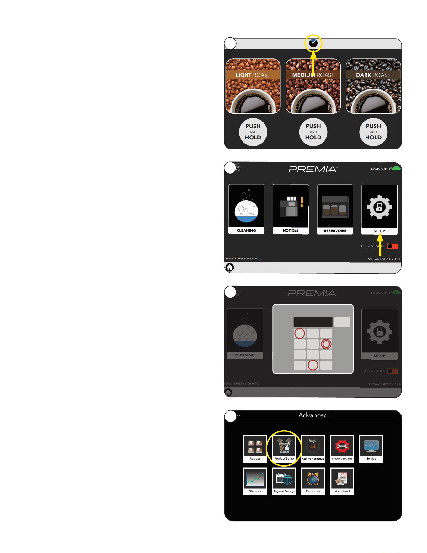
1. Touch and hold the BUNN logo for a few
seconds until Service Access appears
on the display.
2. Select the Advanced Setup icon.
3. Next, enter the passcode 6601.
4. Touch the PRODUCT SETUP icon.
Bean Hoppers Assignment
2
1
4
3
PASSWORD
<
1 3
4 5 6
7 8
0
9
2
****
X
Continued >
42
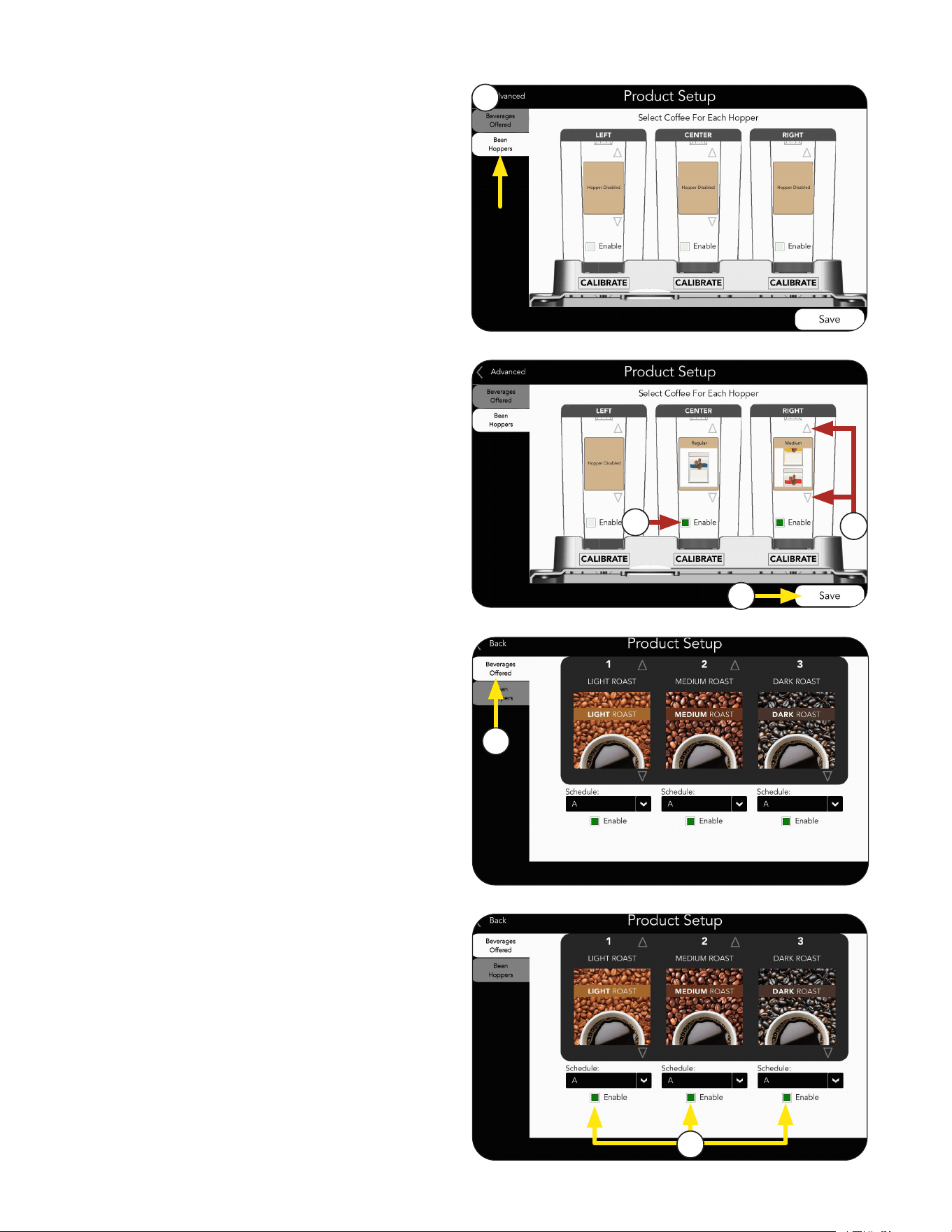
1. Select the Bean Hoppers tab to assign which
Product goes in which hopper.
2. Press the Enable box to select which hopper
to use.
Bean Hoppers Setup
5. Select Beverages Offered tab.
7. Select SAVE if any changes were made.
6. Enable the drink options available for
dispensing.
NOTE: You can also enable drink sizes for
each beverage.
4. Press Save button when finished.
3. After enabling a Hopper, you can use the UP
and DOWN arrows to select an icon for the
Product in that hopper.
1
3
2
5
6
4
RECIPE AND PRODUCT SETUP
43
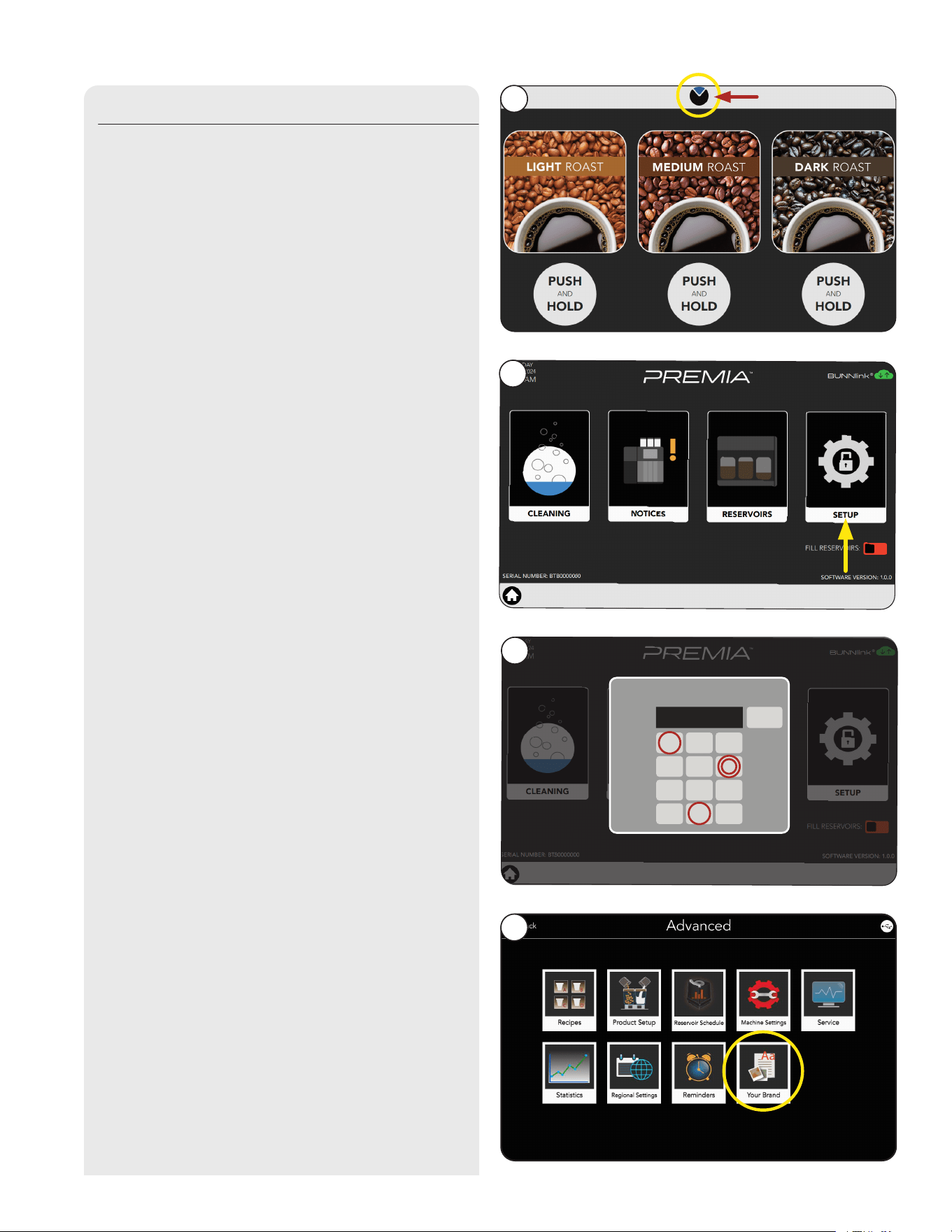
RECIPE AND PRODUCT SETUP
1. Touch and hold the BUNN logo for
a few seconds until Service Access
screen appears.
2. Select the SETUP icon.
3. Next, enter the passcode 6601.
If you have a USB stick with custom files; follow
these steps.
If not, go to Grinder Calibration section.
4. Touch the Your Brand icon.
Importing Custom Configuration Files
Continued >
1
2
4
Press and Hold
3
PASSWORD
<
1 3
4 5 6
7 8
0
9
2
****
X
44
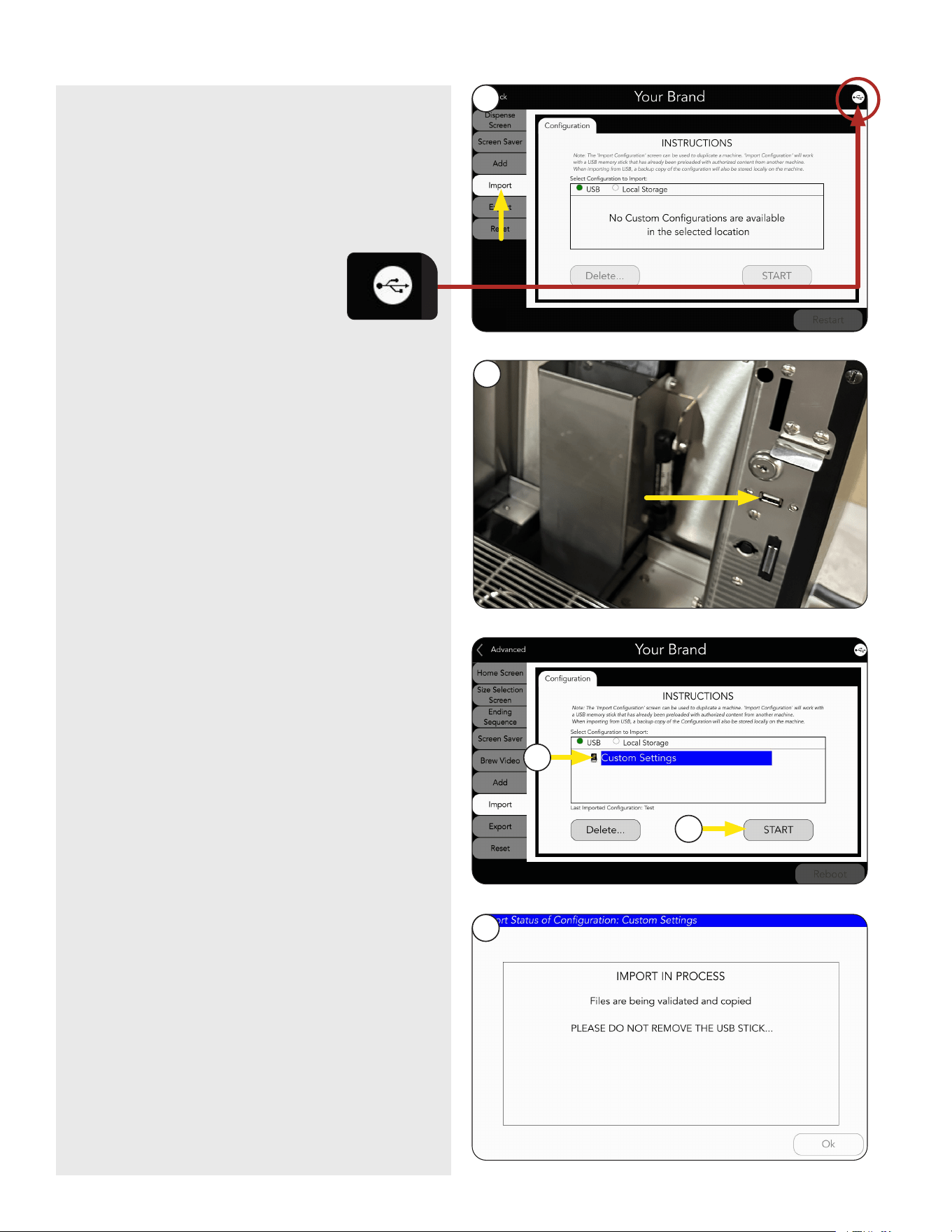
RECIPE AND PRODUCT SETUP
5. Press the Import tab.
7. Select new Configuration file.
8. Press Start button.
9. Screen will show progress of file import.
NOTE: Do not remove USB Stick while files
are copying.
6. Open the Lower Door and Insert USB Stick.
Continued >
5
6
7
8
9
NOTE: To verify a USB is recognized, look
for the connection icon in the upper right
corner of the screen.
continued from previous page
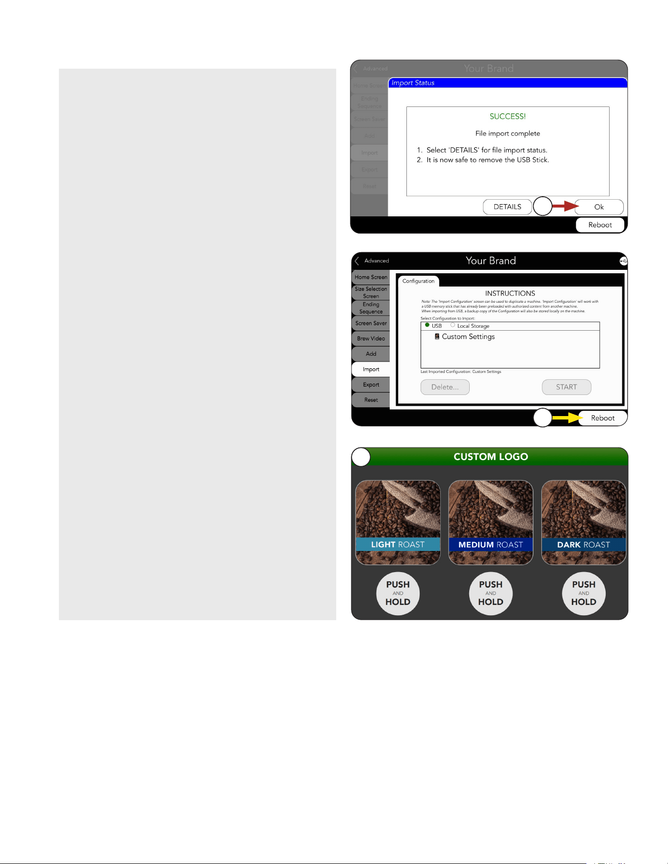
45
12. The machine will update with your custom
Configuration files.
11. Press Reboot button to complete import.
After the machine updates, the Home
screen should appear, and the Products
and variables you imported should be
available.
NOTE: This will restart the machine’s
operating system.
10. When the import is completed, the
OK button can be selected and the
USB stick can be safely removed.
RECIPE AND PRODUCT SETUP
Continued >
10
11
12
continued from previous page
46
PRODUCT AND RECIPE SETUP
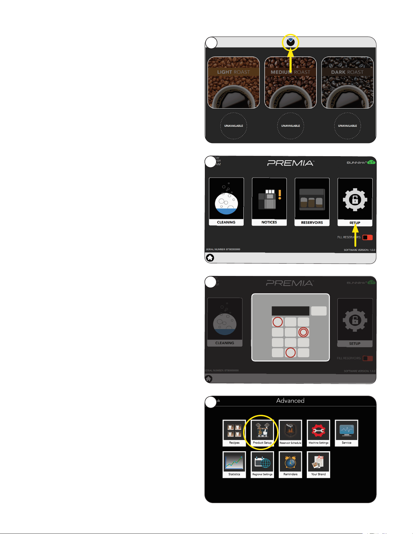
1. Touch and hold the BUNN logo for a few
seconds until Service Access appears
on the display.
2. Select the Advanced icon.
3. Next, enter the passcode 6601.
Grinder Calibration
4. Touch the Product icon.
1
Continued >
1
2
4
3
PASSWORD
<
1 3
4 5 6
7 8
0
9
2
****
X
47
5. Next, touch the Bean hoppers tab.
6. Choose a product to edit.
NOTE: We will use the “Light” as an example.
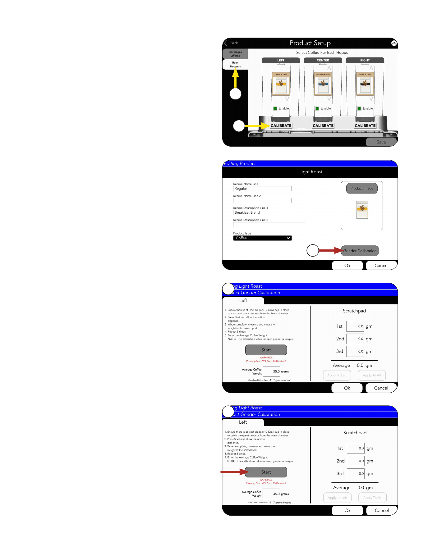
PRODUCT AND RECIPE SETUP
NOTE: The Grinder Calibration button can
also be accessed from the Product tab
under Recipe setup.
8. After choosing a hopper to calibrate, the
calibration screen will appear
NOTE: Choosing the hopper during calibration
is simply telling the machine which grinder
to turn on. A unique calibration is stored for
each product.
9. Next, press the Start button to prime the grinder
with beans.
WARNING: All three hoppers must be locked in
position before starting.
Continued >
7
8
9
5
6
continued from previous page
48
PRODUCT AND RECIPE SETUP
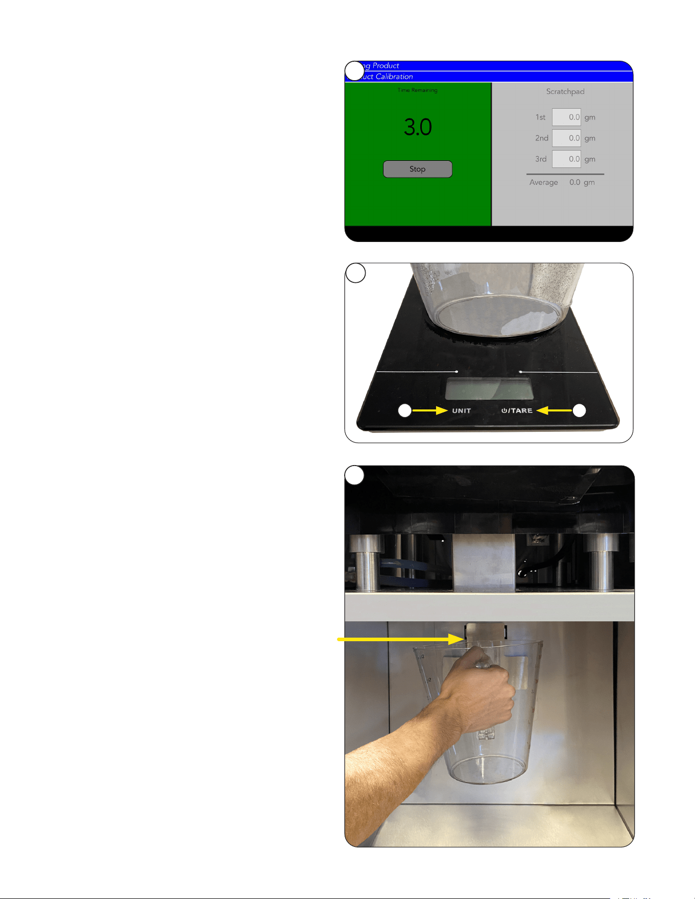
10. Follow on-screen prompts.
11. Tare (zero) empty receiving container
on a digital weigh scale.
a. Select Tare with empty container on
scale.
b. Select grams as unit of measurement.
b
a
12. Place the empty tared container under the
Grounds Chute below the counter.
It’s time to Calibrate the grinder.
Continued >
10
11
12
Grounds Chute
opening shown
below counter
continued from previous page
49
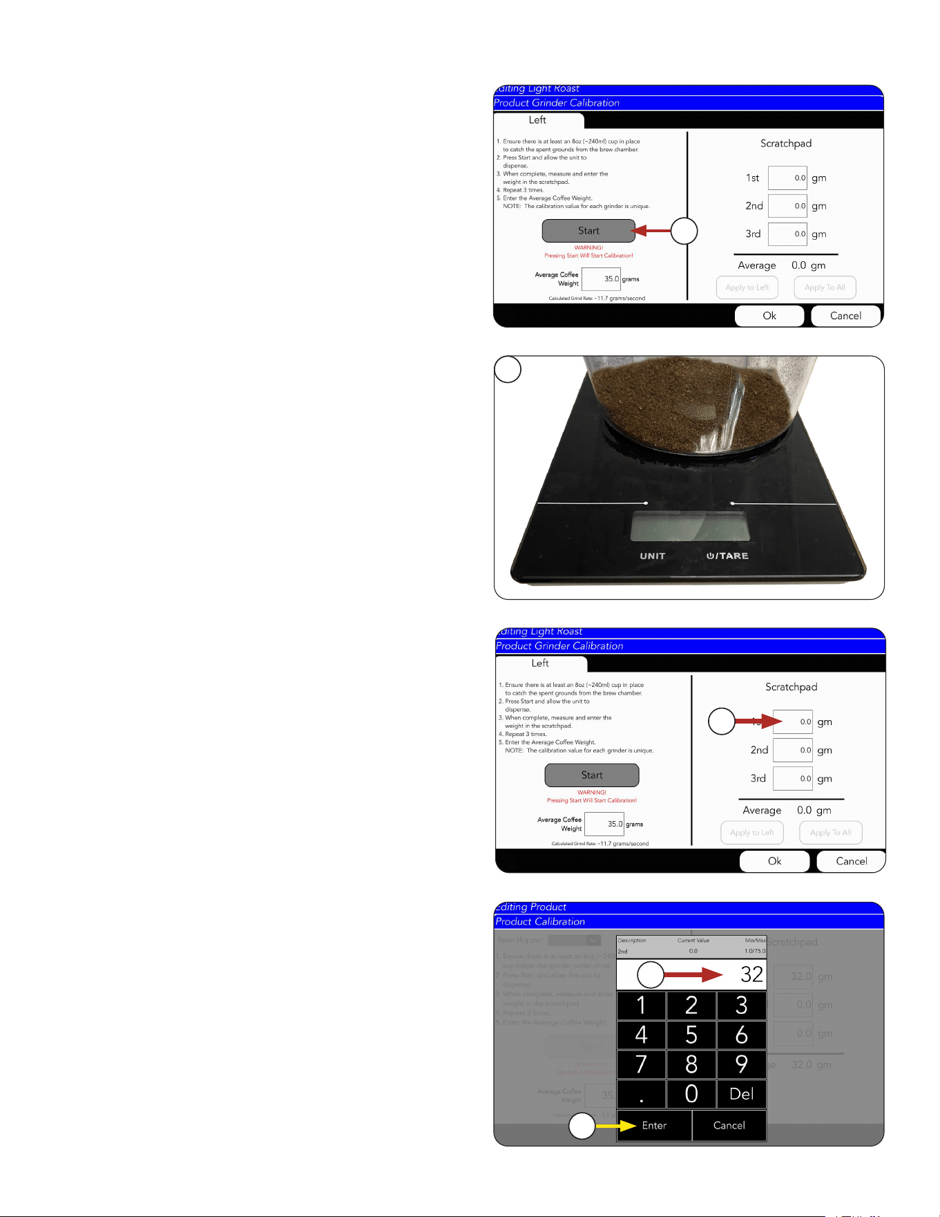
13. Return to Calibration screen.
Press Start button.
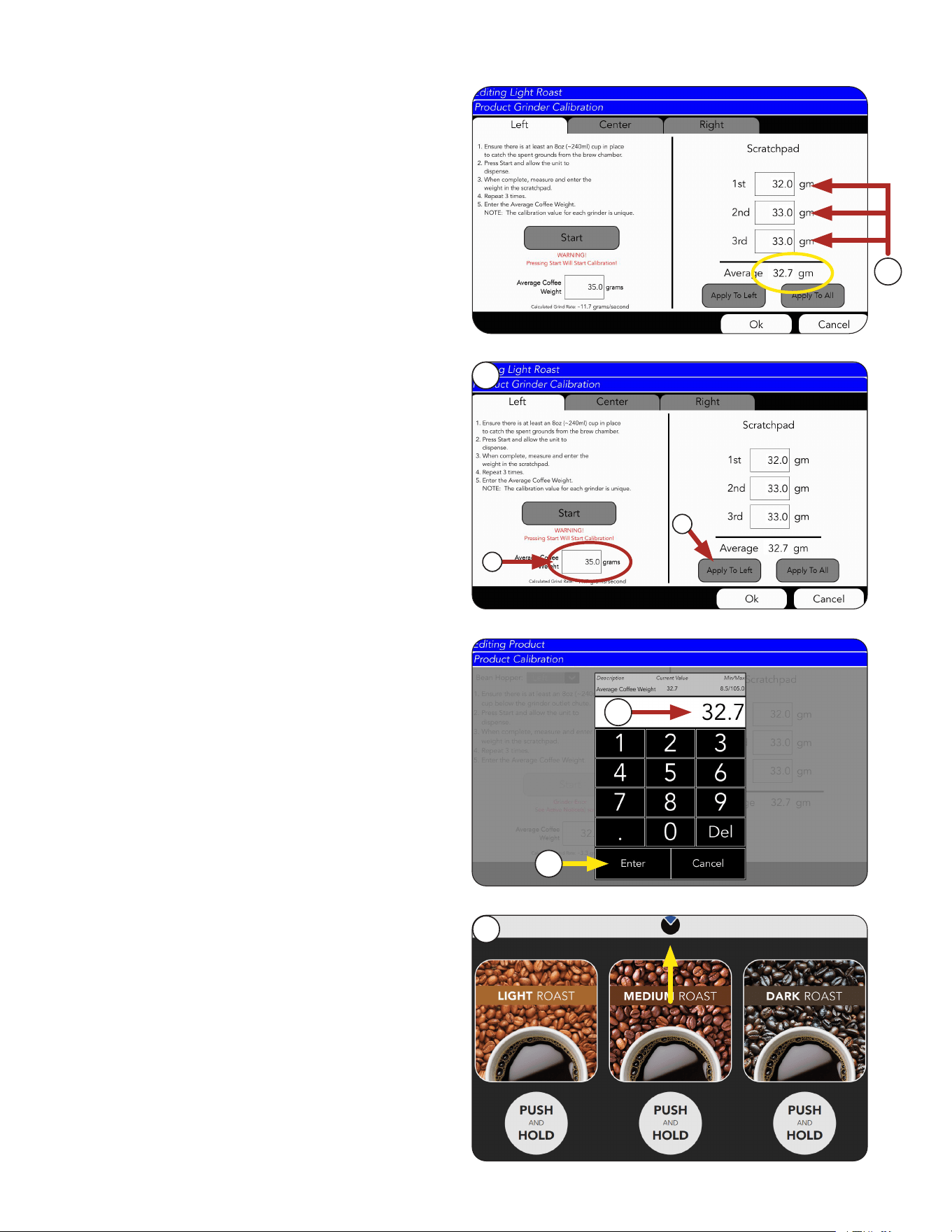
PRODUCT AND RECIPE SETUP
14. Allow time for the grind to finish. Once the grind
is finished, take the container and place it on the
digital scale.
15. Weigh cup.
16. Press the 1st Field to log the weight of the coffee
in the cup.
17. Type the weight of the cup
18. Press Enter.
After pressing the 1st Field to log the weight of the
coffee in the cup, the INPUT Screen will appear for
you to input in these numbers.
Continued >
14
16
17
18
13
continued from previous page
50
PRODUCT AND RECIPE SETUP
21. The Input screen will appear.
Type Average Weight.
22. Press Enter.
20. a. Press Apply To Left button to
automatically input average.
OR
b. Manually press on the Average Coffee
Weight field to fill in this amount.
b
a
NOTE: Repeat calibration steps for the
Center and Right grinders to complete
grinder calibration.
Continued >
21
20
22
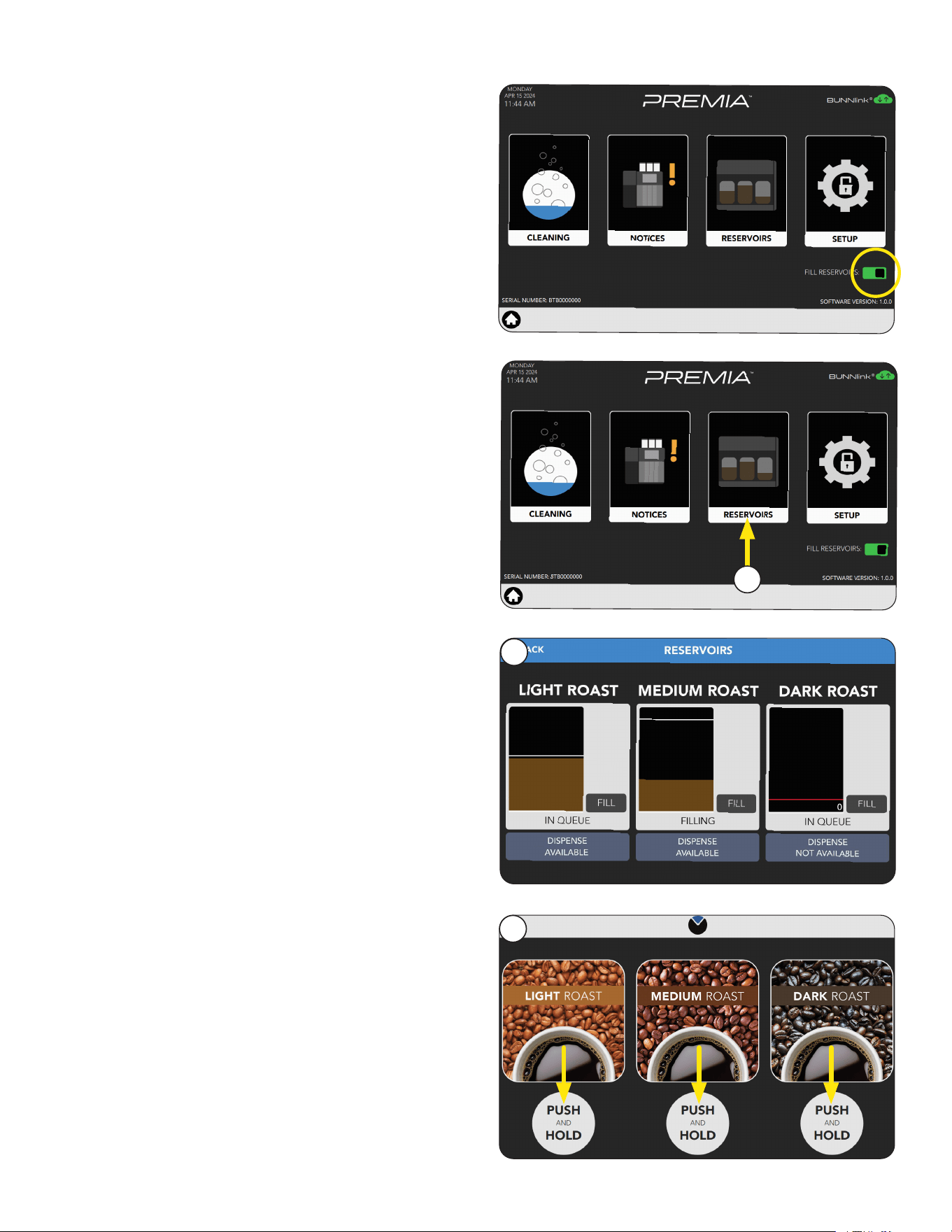
Filling Reservoirs
You can check the status of each reservoir using
the Service Access screen.
1. Press the BUNN logo for a few seconds until
Service Access appears on the display.
1
Empty the cup, then repeat Steps 1 - 10 two more
times to fill in all 3 weight fields.
19. Note the Average Weight of the
three tests.
For this example it’s 32.7 grams.
19
continued from previous page
51
Filling Reservoirs
2. Select the Fill Reservoirs button.
PRODUCT AND RECIPE SETUP
3. This screen will display the volume level for each
reservoir.
3
The first screen to appear is the Customer Interface
screen, also known as the Home Screen.
Customer Interface
1. After placing a cup under the dispense nozzle,
available drinks are dispensed by pushing and
holding the on-screen button below the bever-
age of choice.
1
2. Select the Reservoirs icon.
2
Continued >
52
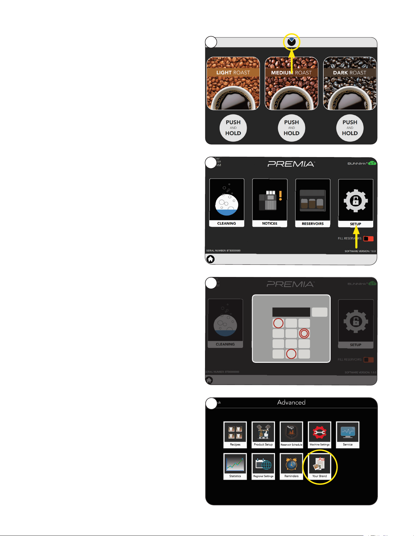
SETUP MENU
1. Press the BUNN logo for a few seconds until
Service Access appears on the display.
2. Select the Advanced Setup icon.
3. Next, enter the passcode 6601.
4. Touch the Your Brand icon.
Your Brand
2
1
4
3
PASSWORD
<
1 3
4 5 6
7 8
0
9
2
****
X
53
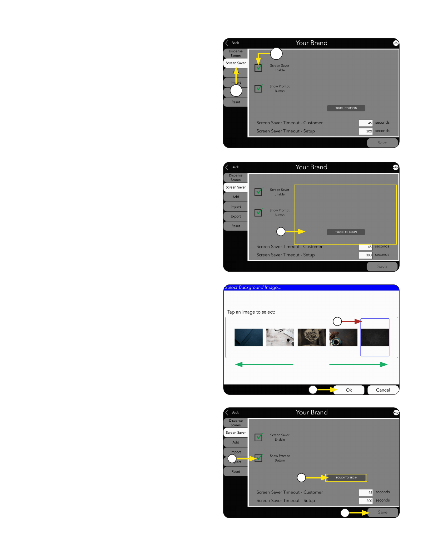
SETUP MENU
The Your Brand screen contains pages that can be
accessed by selecting a tab on the left of the screen
and contains customization options for the machine.
SCREEN SAVER
1. Select Screensaver tab.
2. Check Screen Saver Enable box.
When enabled, the screensaver can be adjusted:
Options Available:
a. Select Screen Saver image.
1. CHANGING SCREENSAVER IMAGE
b. A selection screen will open. If there
are more images available than shown,
scroll side-to-side to view library.
Then click selected image.
c. Press OK.
NOTE: Screen Saver size should be
1024 x 1280 pixels.
a
c
b
1
2
a. Select Show Prompt Button box.
b. Select Prompt Button to edit text.
c. Select Save.
2. SHOW PROMPT BUTTON
a
c
b
continued from previous page
54
OPERATION
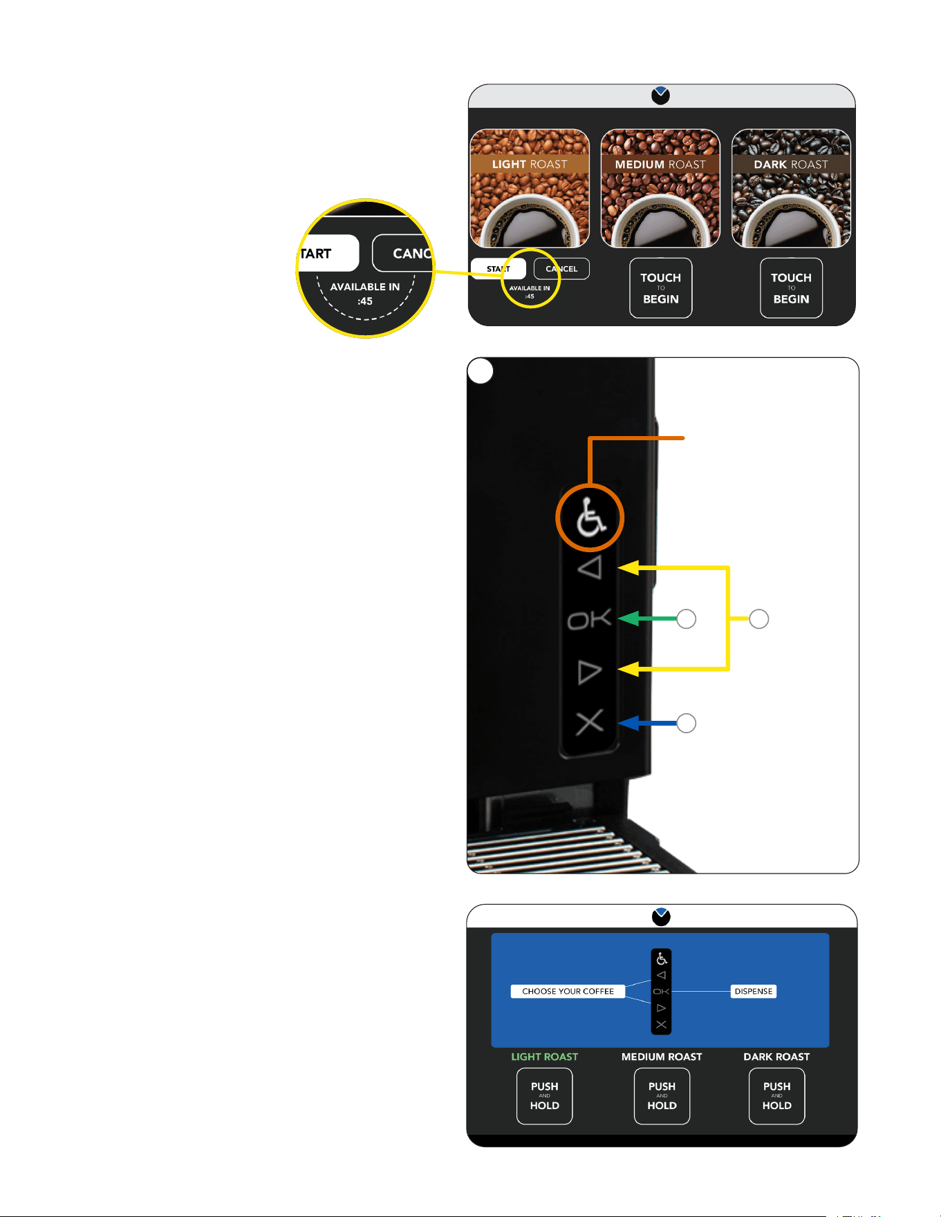
1. To activate the ADA screen interface, the
user must press the Accessibility symbol
(wheelchair icon).
NOTE: A description of the button functions can
be accessed through the Accessibility symbol
(wheelchair icon).
2. When activated, the screen will have a blue
banner across the top, and a blue highlight
around the item being selected.
ADA Interface
3. Navigate around the screens using the Left and
Right arrows on the ADA interface.
a. Select a beverage.
b. Press and Hold the OK button to
dispense.
c. Pressing the X cancels the selection.
1
NOTE: Pressing the
"Activation" button
at any time will exit
ADA mode.
b
c
a
Brew on Demand mode.
Anytime a reservoir schedule is programmed to hold
zero ounces then the machine will operate in the
Brew on Demand mode.
Customer Interface
55
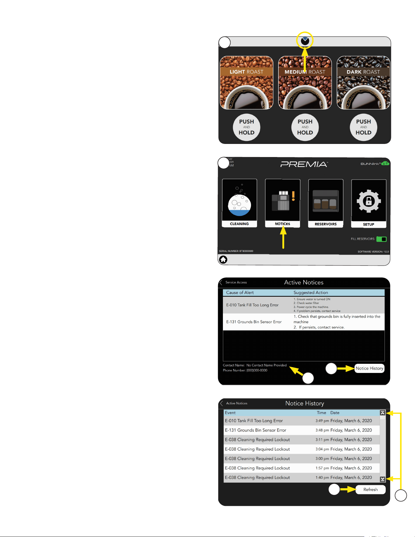
3. The screen will display by Name & Description,
any faults that have occurred, give probable
causes, and a solution to clear the fault.
The Notice History button is located in the
lower right corner of the screen, and can be
used to view previous events (Notices).
4. Service Contact information is also provided.
5. Use the Up or Down Arrows shown on the
right side of the screen to scroll through the
events list.
6. Press the Refresh button located in the lower
right portion of the screen to refresh the list.
ACTIVE NOTICES
2. From the Service Access screen, press the
Active Notices icon.
1. Touch and hold the BUNN logo for a few
seconds until Service Access appears
on the display.
1
2
3
4
6
5

56