
A. Introduction
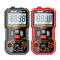
This product is the world's first 9999 counts palm-size auto-ranging digital
multieter. The product is battery-powered with true-rms, LCD display and backlight.
B. Safety Information
To avoid possible electrical shock, fire, or personal injury, please read all safety
information before you use the product.
(1) Do NOT exceed the “maximum value” indicated in the Specification.
(2) Examine the connection of the test leads and the insulation of the product
before measuring voltage higher than 36V DC or 25V AC.
(3) Disconnect the test leads from the circuit before changing the mode。
(4) Misuse of mode or range can lead to hazards, be cautious. “OL” will be shown
on the display when the input is out of range.
(5) Safety symbols:
C. Specifications
Hazardous Voltage
Earth
Double Insulated
Low Battery
Risk of Danger. Check the User Manual.
User Manual
- 1 - - 3 -
- 4 -
- 2 -
D. Instruction
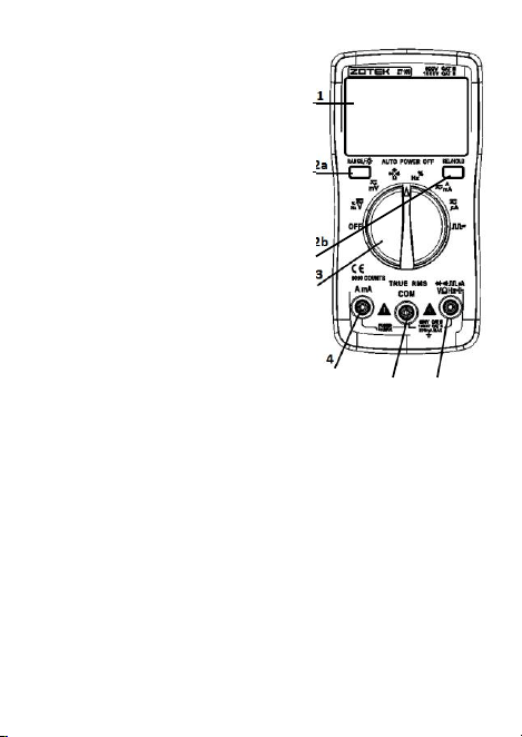
(1) Front Panel(see the picture on the right)
1. LCD display
2. Bottons
2a. RANGE/Backlight: press this botton to enter
the manual range; each push increases the
range; when the highest range is reached,
next push will go back to the lowest range;
to exit the manual range mode, turn the
Rotary Switch to another mode and then
turn it back. To turn on the backlight, press
this botton for more than 2 seconds; long-
press again to turn off.
2b. SELECT/HOLD: To toggle between different
testing modes (functions), press this botton.
To hold the current reading, press this
botton for more than 2 seconds and you
will see “HOLD” on the display; long-press
again to turn off.
3. Rotary Switch: To change mode or range。
(from OFF, clockwise)
3a. OFF
3b. DC Voltage (V)/AC Voltage (V)/Frequency (high voltage low frequency)/Duty
Cycle
3c. DC Voltage (mV)/AC Voltage (mV)
3d. Resistance/Continuity/Diode/Capacitance
3e. Frequency (low voltage high frequency)/Duty Cycle
3f. DC Current (mA&A)/AC Current (mA&A)
3g. DC Current (μA)/AC Current (μA)
3h. Square Wave Output
4. AmA: Input terminal for current (mA&A) measurements.
5. COM: Common terminal for all measurements.
6. VΩHz: Input terminal for voltage, current (μA), frequency, duty cycle, resistance,
continuity, diode, capacitance measurements. Outout terminal for square wave.
(2) Measure AC/DC Voltage
1. Connect the black test lead to the COM Terminal and connect the red test lead to
the VΩHz Terminal;
2. Turn the rotary switch to the DC Voltage (V) Mode, or the DC Voltage (mV) Mode;
3. Press SELECT to toggle between AC/DC;
4. Touch the probes to the correct test points of the circuit to measure the voltage;
5. Read the measured voltage on the display.
*Caution:
a. Do not measure voltage that exceeds the MAX Value as indicated in the
Specifications;
b. Do not touch high voltage circuit during measurements.
1
2a
2b
3
4
5
6
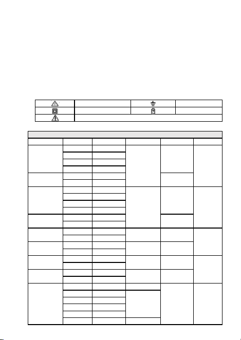
Electrical Specifications
Function
Range
Resolution
Accuracy
MAX. Value
Other
DC Voltage
(V)
999.9mV
0.1mV
±(0.5%+3)
999.9V
9.999V
0.001V
99.99V
0.01V
999.9V
0.1V
DC Voltage
(mV)
9.999mV
0.001mV
99.99mV
99.99mV
0.01mV
AC Voltage
(V)
999.9mV
0.1mV
±(1.0%+3)
750V
40Hz-1kHz
9.999V
0.001V
99.99V
0.01V
750.0V
0.1V
AC Voltage
(mV)
9.999mV
0.001mV
99.99mV
99.99mV
0.01mV
DC Current
(mA&A)
999.9mA
0.1mA
±(1.0%+3)
9.999A
9.999A
0.001A
DC Current
(μA)
99.99μA
0.01μA
±(0.8%+3)
999.9μA
999.9μA
0.1μA
AC Current
(mA&A)
999.9mA
0.1mA
±(1.2%+3)
9.999A
40Hz-1kHz
9.999A
0.001A
AC Current
(μA)
99.99μA
0.01μA
±(1.0%+3)
999.9μA
999.9μA
0.1μA
Resistance
99.99Ω
0.01Ω
±(1.0%+3)
9.999MΩ
999.9Ω
0.1Ω
±(0.5%+3)
9.999kΩ
0.001kΩ
99.99kΩ
0.01kΩ
999.9kΩ
0.1kΩ
9.999MΩ
0.001MΩ
±(1.5%+3)
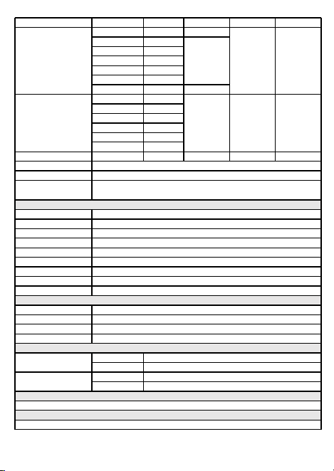
Function
Range
Resolution
Accuracy
MAX. Value
Other
Capacitance
9.999nF
0.001nF
±(5.0%+20)
9.999mF
99.99nF
0.01nF
±(2.0%+5)
999.9nF
0.1nF
9.999μF
0.001μF
99.99μF
0.01μF
999.9μF
0.1μF
9.999mF
0.001mF
±(5.0%+5)
Frequency
99.99Hz
0.01Hz
±(0.1%+2)
9.999MHz
999.9Hz
0.1Hz
9.999kHz
0.001kHz
99.99kHz
0.01kHz
999.9kHz
0.1kHz
9.999MHz
0.001MHz
Duty Cycle
1%~99%
0.1%
±(0.1%+2)
Diode
√
Continuity
√
Square Wave Output
50Hz/100Hz/200Hz/300Hz/400Hz/500Hz/600Hz/700Hz/800Hz/
900Hz/1000Hz/2000Hz/3000Hz/4000Hz/5000Hz
General Specifications
Display(LCD)
9999 Counts
Ranging
Auto/Manual
Material
ABS
Update Rate
3 Times/Second
Ture RMS
√
Back Light
√
Data Hold
√
Low Battery Indication
√
Auto Power Off
√
Mechanical Specifications
Dimension
130*65*32mm
Weight
114g/128g(w/ batteries)
Battery Type
1.5V AAA Batteries * 2
Warranty
One year
Environmental Specifications
Operating
Temperature
0~40℃
Humidity
<75%
Storage
Temperature
-20~60℃
Humidity
<80%
Safety Specifications
EN 61010-1:2010; EN 61326-1:2013, FCC Part 15 Subpart B:2016
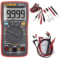
Standard Accessories
Battery * 2pcs; Test Lead * 1 pair; Drawstring Pouch * 1pc; English User Manual; Gift Box
A. Introduction
This product is the world's first 9999 counts palm-size auto-ranging digital
multieter. The product is battery-powered with true-rms, LCD display and backlight.
B. Safety Information
To avoid possible electrical shock, fire, or personal injury, please read all safety
information before you use the product.
(1) Do NOT exceed the “maximum value” indicated in the Specification.
(2) Examine the connection of the test leads and the insulation of the product
before measuring voltage higher than 36V DC or 25V AC.
(3) Disconnect the test leads from the circuit before changing the mode。
(4) Misuse of mode or range can lead to hazards, be cautious. “OL” will be shown
on the display when the input is out of range.
(5) Safety symbols:
C. Specifications
Hazardous Voltage
Earth
Double Insulated
Low Battery
Risk of Danger. Check the User Manual.
User Manual
- 1 - - 3 -
- 4 -
- 2 -
D. Instruction
(1) Front Panel(see the picture on the right)
1. LCD display
2. Bottons
2a. RANGE/Backlight: press this botton to enter
the manual range; each push increases the
range; when the highest range is reached,
next push will go back to the lowest range;
to exit the manual range mode, turn the
Rotary Switch to another mode and then
turn it back. To turn on the backlight, press
this botton for more than 2 seconds; long-
press again to turn off.
2b. SELECT/HOLD: To toggle between different
testing modes (functions), press this botton.
To hold the current reading, press this
botton for more than 2 seconds and you
will see “HOLD” on the display; long-press
again to turn off.
3. Rotary Switch: To change mode or range。
(from OFF, clockwise)
3a. OFF
3b. DC Voltage (V)/AC Voltage (V)/Frequency (high voltage low frequency)/Duty
Cycle
3c. DC Voltage (mV)/AC Voltage (mV)
3d. Resistance/Continuity/Diode/Capacitance
3e. Frequency (low voltage high frequency)/Duty Cycle
3f. DC Current (mA&A)/AC Current (mA&A)
3g. DC Current (μA)/AC Current (μA)
3h. Square Wave Output
4. AmA: Input terminal for current (mA&A) measurements.
5. COM: Common terminal for all measurements.
6. VΩHz: Input terminal for voltage, current (μA), frequency, duty cycle, resistance,
continuity, diode, capacitance measurements. Outout terminal for square wave.
(2) Measure AC/DC Voltage
1. Connect the black test lead to the COM Terminal and connect the red test lead to
the VΩHz Terminal;
2. Turn the rotary switch to the DC Voltage (V) Mode, or the DC Voltage (mV) Mode;
3. Press SELECT to toggle between AC/DC;
4. Touch the probes to the correct test points of the circuit to measure the voltage;
5. Read the measured voltage on the display.
*Caution:
a. Do not measure voltage that exceeds the MAX Value as indicated in the
Specifications;
b. Do not touch high voltage circuit during measurements.
1
2a
2b
3
4
5
6
Electrical Specifications
Function
Range
Resolution
Accuracy
MAX. Value
Other
DC Voltage
(V)
999.9mV
0.1mV
±(0.5%+3)
999.9V
9.999V
0.001V
99.99V
0.01V
999.9V
0.1V
DC Voltage
(mV)
9.999mV
0.001mV
99.99mV
99.99mV
0.01mV
AC Voltage
(V)
999.9mV
0.1mV
±(1.0%+3)
750V
40Hz-1kHz
9.999V
0.001V
99.99V
0.01V
750.0V
0.1V
AC Voltage
(mV)
9.999mV
0.001mV
99.99mV
99.99mV
0.01mV
DC Current
(mA&A)
999.9mA
0.1mA
±(1.0%+3)
9.999A
9.999A
0.001A
DC Current
(μA)
99.99μA
0.01μA
±(0.8%+3)
999.9μA
999.9μA
0.1μA
AC Current
(mA&A)
999.9mA
0.1mA
±(1.2%+3)
9.999A
40Hz-1kHz
9.999A
0.001A
AC Current
(μA)
99.99μA
0.01μA
±(1.0%+3)
999.9μA
999.9μA
0.1μA
Resistance
99.99Ω
0.01Ω
±(1.0%+3)
9.999MΩ
999.9Ω
0.1Ω
±(0.5%+3)
9.999kΩ
0.001kΩ
99.99kΩ
0.01kΩ
999.9kΩ
0.1kΩ
9.999MΩ
0.001MΩ
±(1.5%+3)
Function
Range
Resolution
Accuracy
MAX. Value
Other
Capacitance
9.999nF
0.001nF
±(5.0%+20)
9.999mF
99.99nF
0.01nF
±(2.0%+5)
999.9nF
0.1nF
9.999μF
0.001μF
99.99μF
0.01μF
999.9μF
0.1μF
9.999mF
0.001mF
±(5.0%+5)
Frequency
99.99Hz
0.01Hz
±(0.1%+2)
9.999MHz
999.9Hz
0.1Hz
9.999kHz
0.001kHz
99.99kHz
0.01kHz
999.9kHz
0.1kHz
9.999MHz
0.001MHz
Duty Cycle
1%~99%
0.1%
±(0.1%+2)
Diode
√
Continuity
√
Square Wave Output
50Hz/100Hz/200Hz/300Hz/400Hz/500Hz/600Hz/700Hz/800Hz/
900Hz/1000Hz/2000Hz/3000Hz/4000Hz/5000Hz
General Specifications
Display(LCD)
9999 Counts
Ranging
Auto/Manual
Material
ABS
Update Rate
3 Times/Second
Ture RMS
√
Back Light
√
Data Hold
√
Low Battery Indication
√
Auto Power Off
√
Mechanical Specifications
Dimension
130*65*32mm
Weight
114g/128g(w/ batteries)
Battery Type
1.5V AAA Batteries * 2
Warranty
One year
Environmental Specifications
Operating
Temperature
0~40℃
Humidity
<75%
Storage
Temperature
-20~60℃
Humidity
<80%
Safety Specifications
EN 61010-1:2010; EN 61326-1:2013, FCC Part 15 Subpart B:2016
Standard Accessories
Battery * 2pcs; Test Lead * 1 pair; Drawstring Pouch * 1pc; English User Manual; Gift Box

- 5 - - 7 -
- 8 -
- 6 -
(10) Square Wave Output
1. Connect the black test lead to the COM Terminal and connect the red test
lead to the VΩHz Terminal; ;
2. Turn the rotary switch to the Square Wave Output Mode, and the default
output frequency is 50Hz, to change the output frequency, press the SELECT
botton;
3. Touch the probes to the desired test points.
*Caution:
a. Do not input voltage at the Square Wave Output Mode.
(11) Auto Power Off
1. The product automatically powers off after 15 minutes of inactivity;
2. The built-in beeper beeps 5 times 1 minute before power off;
3. To restart the product, press SELECT botton;
4. To disable the Auto Power Off function, hold down the SELECT botton when
turning on the product, you will hear five beeps if you have successfully
disabled the function.
E. Genearl Maintenance
Beyond replacing batteries and fuses, do not attempt to repair or service the product
unless you are qualified to do so and have the relevant calibration, performance test,
and service instructions.
(1) Do not operate the product around hot, wet, flammable, explosive or magnetic
environments.
(2) Clean the product with damp cloth and mild detergent; do not use abrasives or
solvents.
(3) Remove the input signals before you clean the product.
(4) Remove the batteries if you will not use the product for a long time to prevent
possible battery leak.
(5) When “ ” is shown on the display, batteries shall be replaced as below:
1. Loosen the screw and remove the battery cover;
2. Replace the used batteries with new batteries of the same type;
3. Place the battery cover back and fasten the screw.
(6) Replace fuses as above steps. Use only fuses of the same type as the original
ones.
(3) Measure AC/DC Current (mA&A)
1. Connect the black test lead to the COM Terminal and connect the red test lead
to the AmA Terminal;
2. Turn the rotary switch to the DC Current (mA&A) Mode;
3. Press SELECT to toggle between AC/DC;
4. Break the circuit path to be measured. Then connect the test leads across the
break and apply power;
5. Read the measured current on the display.
*Caution:
a. Do not measure current that exceeds the MAX Value as indicated in the
Specifications;
b. Use the AmA Terminal and the DC Current (mA&A) Mode when you are
measureing an unknown current. Then switch to the Termianl and the Mode if
necessary.
(4) Measure AC/DC Current (mA&A)
1. Connect the black test lead to the COM Terminal and connect the red test lead
to the VΩHz Terminal;
2. Turn the rotary switch to the DC Current (μA) Mode;
3. Press SELECT to toggle between AC/DC;
4. Break the circuit path to be measured. Then connect the test leads across the
break and apply power;
5. Read the measured current on the display.
*Caution:
a. Do not measure current that exceeds the MAX Value as indicated in the
Specifications;
b. Use the AmA Terminal and the DC Current (mA&A) Mode when you are
measureing an unknown current. Then switch to the Termianl and the Mode if
necessary.
(5) Measure Resistance
1. Connect the black test lead to the COM Terminal and connect the red test lead to
the VΩHz Terminal;
2. Turn the rotary switch to the Resistance Mode, and the display will show “OL”;
3. Touch the probes to the desired test points of the circuit to measure the resistance;
4. Read the measured resistance on the display.
*Caution:
a. Disconnect circuit power and discharge all capacitors before you test resistance.
b. Do not input voltage at the Resistance Mode.
(6) Measure Continuity
1. Connect the black test lead to the COM Terminal and connect the red test lead
to the VΩHz Terminal;
2. Turn the rotary switch to the Resistance Mode, press SELECT once to toggle to the
Continuity Mode;
3. Touch the probes to the desired test points of the circuit;
4. The built-in beeper will beep when the resistance is lower than 50Ω, which
indicates a short circuit.
*Caution:
a. Do not input voltage at the Continuity Mode.
(7) Measure Diode
1. Connect the black test lead to the COM Terminal and connect the red test lead to
the VΩHz Terminal;
2. Turn the rotary switch to the Resistance Mode, press SELECT twice to toggle to the
Diode Mode;
3. Connect the red probe to the anode side and the black probe to the cathode side
of the diode being tested;
4. Read the forward bias voltage value on the display;
5. If the polarity of the test leads is reversed with diode polarity or the diode is
broken, the display reading shows “OL”.
*Caution:
a. Do not input voltage at the Diode Mode.
b. Disconnect circuit power and discharge all capacitors before you test diode.
(8) Measure Capacitance
1. Connect the black test lead to the COM Terminal and connect the red test lead to
the VΩHz Terminal;
2. Turn the rotary switch to the Resistance Mode, press SELECT three times to toggle
to the Capacitance Mode;
3. Connect the red probe to the anode side and the black probe to the cathode
side of the capacitor being tested;
4. Read the measured capacitance value on the display once the reading is stablized.
*Caution:
a. Disconnect circuit power and discharge all capacitors before you test capacitance.
(9) Measure Frequency and Duty Cycle
1. Connect the black test lead to the COM Terminal and connect the red test lead to
the VΩHz Terminal;
2. To measure high voltage low frequency, turn the rotary switch to the DC Voltage(V)
Mode; press SELECT twice to toggle to the Frequency Mode or press SELECT three
times to toggle to the Duty Cycle Mode. To measure low voltage high frequency,
turn the rotary switch to the Frequency Mode; press SELECT once to toggle to the
Duty Cycle Mode;
3. Touch the probes to the desired test points of the circuit;
4. Read the measured frequency/duty cycle value on the display.
Warning:
1. Do NOT exceed the “maximum value” indicated in the Specification;
2. Do NOT input voltage at the Current Mode, the Resistance Mode, the Diode
Mode, the Continuity Mode, or the Temperature Mode;
3. Do NOT use the product when the batteries or the battery cover is not placed
properly;
4. Turn off the product and remove the test leads from the test points before
changing batteries or fuses.
F. Troubleshooting
If your product do not function as normal, the following steps may help you. If the
problem still cannot be solved, please contact your dealer.
Problem
Possible Reason
Display Mulfunction
Low battery; replace batteries
Symbol
Replace batteries
No current input
Replace fuse
LIMITED WARRANTY
AND LIMITATION OF LIABILITY
Customers enjoy one-year warranty from the date of purchase. This warranty
does not cover fuses, disposable batteries, or damage from accident, neglect,
misuse, alternation, contamination, or abnormal conditions of operation or
handling.
All rights reserved. Specifications are subject to change without notice.
Do not input voltage exceeds 36V DC or 25V AC when you are at the
setting of measuring current.