
Guida di installazione
Installation Guide


www.fhiaba.com · [email protected] · Info Line +39 0434 420160 www.fhiaba.com · [email protected] · Info Line +39 0434 420160
41
INDEX
EN
1
1.1
1.2
IMPORTANT INSTRUCTIONS
Important safety instructions......................................................................................................................................
Children safety..................................................................................................................................................................
42
42
42
2
2.1
2.2
2.3
2.4
2.5
2.7
2.8
2.9
2.10
2.11
TECHNICAL REQUIREMENTS
Appliance features and installation requirements................................................................................................
Installation niche features: Integrated Series - 1T - 0T - 0H Models...............................................................
Installation niche features: Integrated Series - 0F Column Models.................................................................
Installation niche features: Classic Series - 1T - 0T - 0H Models.....................................................................
Installation niche features: Classic Series - 0F Column Models.......................................................................
Installation niche features: X-Pro Series..................................................................................................................
Installation niche features: X-Pro Series - 0F Column Models..........................................................................
Installation niche features: Country Series..............................................................................................................
Installation niche features: Brilliance-Integrated Series.....................................................................................
Installation niche features: Brilliance-Classic Series...........................................................................................
42
42
44
45
46
47
49
50
51
52
53
3
3.1
3.2
3.3
PREPARING TO INSTALL
Transport to installation site and unpacking...........................................................................................................
Electrical and Water connection..................................................................................................................................
Levelling.............................................................................................................................................................................
54
54
54
55
4
4.1
4.2
4.3
4.4
4.5
4.6
4.7
4.8
4.9
4.10
4.11
4.12
4.13
PANELS MOUNTING
Decorative door and Bottom-Drawer panels layout.............................................................................................
Decorative panels layout for Fridge with one Bottom-Drawer (1T/0T)..........................................................
Decorative panels layout for Fridge with two Bottom-Drawers (0H)..............................................................
Decorative panels layout for Fridge with Glass door and one Bottom-Drawer (1T/0T)............................
Decorative panels layout for Fridge with Glass door Brilliance........................................................................
Decorative panels layout for Fridge with Glass door and two Bottom-Drawers (0H)................................
Decorative panels layout for Fridge Column (0F)..................................................................................................
Decorative panels layout for Fridge column with glass door (0F)...................................................................
Panels Dimensions One Bottom - Drawer (1T/0T models).................................................................................
Panels Dimensions Two Bottom - Drawers (0H models).....................................................................................
Panels Dimensions Column model (0F models)....................................................................................................
Mounting the handles....................................................................................................................................................
Mounting panels to the door and the drawer...........................................................................................................
56
56
59
59
60
61
62
63
64
65
66
67
68
68
5
5.1
5.2
5.3
5.4
INSTALLATION
Built-in installation of single appliance....................................................................................................................
Built-in installation of two or more appliances......................................................................................................
Free-standing installation two or more appliances..............................................................................................
Maximum cabinet depth over “Integrated” refrigerator with single door panel..........................................
70
70
70
72
73
6
6.1
6.2
6.3
6.4
6.5
COMPLETING THE INSTALLATION
Anti-tipping safety assembly........................................................................................................................................
Mounting the handles on stainless front..................................................................................................................
Ventilation..........................................................................................................................................................................
Post installation control................................................................................................................................................
Start Up..............................................................................................................................................................................
74
74
74
75
76
76
www.fhiaba.com · [email protected] · Info Line +39 0434 420160 www.fhiaba.com · [email protected] · Info Line +39 0434 420160
42
1.1 Important safely instruction
Symbols used in the Guide:
Note
Tips for the correct use of the appliance
Important
Directions to avoid appliance damage
Warning
directions to prevent injury
1.2 Children safety
If this appliance is replacing an existing appliance
which must be removed or disposed of, make sure
that it does not become a dangerous trap for children
by cutting its power supply cable and rendering it
impossible to close the door.
Use the same caution at the end of the lifespan of the
new appliance.
Important!
Dimensions in parentheses are in inches.
Weights in parentheses are in pounds.
Temperatures in parentheses are
in Fahrenheit degrees.
1. IMPORTANT INSTRUCTIONS
Appliance
dimensions
Integrated
Series 449
w: 449 mm (17 5/8”)
h: 2050 mm (80 3/4”)
d: 615 mm (24 1/4”) 0F
Series 599
w: 599 mm (23 5/8”)
h: 2050 mm (80 3/4”)
d: 610 mm (24”) 1T/0T/0H
d: 615 mm (24 1/4”) 0F
Series 749
w: 749 mm (29 1/2”)
h: 2050 mm (80 3/4”)
d: 610 mm (24”) 1T/0T/0H
d: 615 mm (24 1/4”) 0F
Series 899
w: 899 mm (35 3/8”)
h: 2050 mm (80 3/4”)
d: 610 mm (24”) 1T/0T/0H
d: 615 mm (24 1/4”) 0F
Appliance
dimensions
Classic
Series 449
w: 449 mm (17 5/8”)
h: 2050 mm (80 3/4”)
d: 640 mm (25 1/4”) 0F
Series 599
w: 599 mm (23 5/8”)
h: 2050 mm (80 3/4”)
d: 635 mm (25”) 1T/0T/0H
d: 640 mm (25 1/4”) 0F
Series 749
w: 749 mm (29 1/2”)
h: 2050 mm (80 3/4”)
d: 635 mm (25”) 1T/0T/0H
d: 640 mm (25 1/4”) 0F
Series 899
w: 899 mm (35 3/8”)
h: 2050 mm (80 3/4”)
d: 635 mm (25”) 1T/0T/0H
d: 640 mm (25 1/4”) 0F
Appliance
dimensions
X-Pro / Country
Series 449
w: 449 mm (17 5/8”)
h: 2120 mm (83 1/2”)
d: 640 mm (25 1/4”) 0F
Series 599
w: 599 mm (23 5/8”)
h: 2120 mm (83 1/2”)
d: 635 mm (25”) 1T/0T/0H
d: 640 mm (25 1/4”) 0F
Series 749
w: 749 mm (29 1/2”)
h: 2120 mm (83 1/2”)
d: 635 mm (25”) 1T/0T/0H
d: 640 mm (25 1/4”) 0F
Series 899
w: 899 mm (35 3/8”)
h: 2120 mm (83 1/2”)
d: 635 mm (25”) 1T/0T/0H
d: 640 mm (25 1/4”) 0F
2.1 Appliance features and installation
requirements
2. TECHNICAL REQUIREMENTS

www.fhiaba.com · [email protected] · Info Line +39 0434 420160 www.fhiaba.com · [email protected] · Info Line +39 0434 420160
43
Appliance
dimensions
Brilliance
-Integrated
Series 599
w: 599 mm (23 5/8”)
h: 2050 mm (80 3/4”)
d: 610 mm (24”)
Series 749
w: 749 mm (29 1/2”)
h: 2050 mm (80 3/4”)
d: 610 mm (24”)
Series 899
w: 899 mm (35 3/8”)
h: 2050 mm (80 3/4”)
d: 610 mm (24”)
Appliance
dimensions
Brilliance-Classic
Series 599
w: 599 mm (23 5/8”)
h: 2050 mm (80 3/4”)
d: 635 mm (25”)
Series 749
w: 749 mm (29 1/2”)
h: 2050 mm (80 3/4”)
d: 635 mm (25”)
Series 899
w: 899 mm (35 3/8”)
h: 2050 mm (80 3/4”)
d: 635 mm (25”)
Appliance
dimensions
Integrated / Classic
Series 449
w: 650 mm (25 5/8”)
h: 2210 mm (87”)
d: 800 mm (31 1/2”)
Series 599
w: 650 mm (25 5/8”)
h: 2210 mm (87”)
d: 800 mm (31 1/2”)
Series 749
w: 800 mm (31 1/2”)
h: 2210 mm (87”)
d: 800 mm (31 1/2”)
Series 899
w: 950 mm (37 3/8”)
h: 2210 mm (87”)
d: 800 mm (31 1/2”)
Appliance
dimensions
X-Pro / Country
/Brilliance
Series 449
w: 650 mm (25 5/8”)
h: 2260 mm (89”)
d: 800 mm (31 1/2”)
Series 599
w: 650 mm (25 5/8”)
h: 2260 mm (89”)
d: 800 mm (31 1/2”)
Series 749
w: 800 mm (31 1/2”)
h: 2260 mm (89”)
d: 800 mm (31 1/2”)
Series 899
w: 950 mm (37 3/8”)
h: 2260 mm (89”)
d: 800 mm (31 1/2”)
Weight with
packaging
Series 449
up to 170 kg (375 lb)
Series 599
up to 200 kg (441 lb)
Series 749
up to 220 kg (485 lb)
Series 899
up to 240 kg (529 lb)
Voltage Europe Version:
AC 220-240V 50 Hz
North America Version:
110V 60Hz
Power supply
cable
Europe Version:
Schuko 16 A plug
North America Version:
15 A
Potable water
supply pressure
from 0.05 MPa to 0.5 MPa
(0.5 Bar - 5 Bar)
Water supply tube - n°2 fittings 3/4” to 1/4”
- mt 5 of alimentary water
tube 1/4”
- n°3 90° fittings 1/4”
- n°1 water filter support
(provided only with 0FZ
models)
Provided
installation
accessories
- Customized panels
mounting Kit
- Anti-tipping Kit (B04000200)
- Lateral connecting kit
(KCLIT/KCLIH)
- 4 mm (1/8”) allen wrench
Additional
equipment
necessary
- Phillips head screwdriver
- wood and percussion drill
- 2.5 mm (1/8”) bit for wood
- 8 mm (3/8”) bit for walls
- 17 mm (3/4”) wrench
EN
www.fhiaba.com · [email protected] · Info Line +39 0434 420160 www.fhiaba.com · [email protected] · Info Line +39 0434 420160
44
STANDARD NICHE WIDTH
MINIMUM NICHE WIDTH WITH
PORTAL
S899: 900 (35 1/2”) S899: 903 (35 3/8”)
S749: 750 (29 5/8”) S749: 753 (29 3/4”)
S599: 600 (23 3/4”) S599: 603 (23 7/8”)
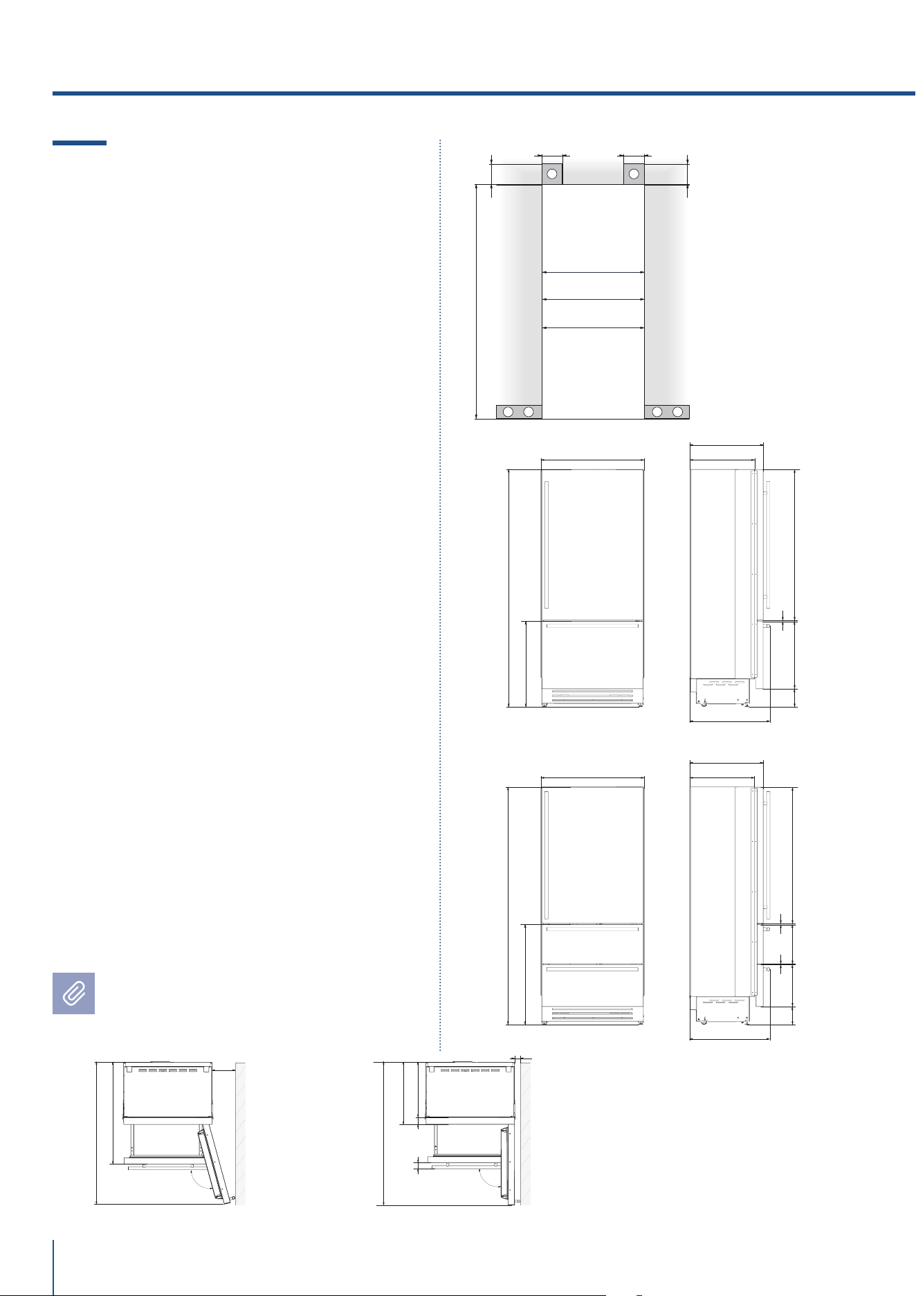
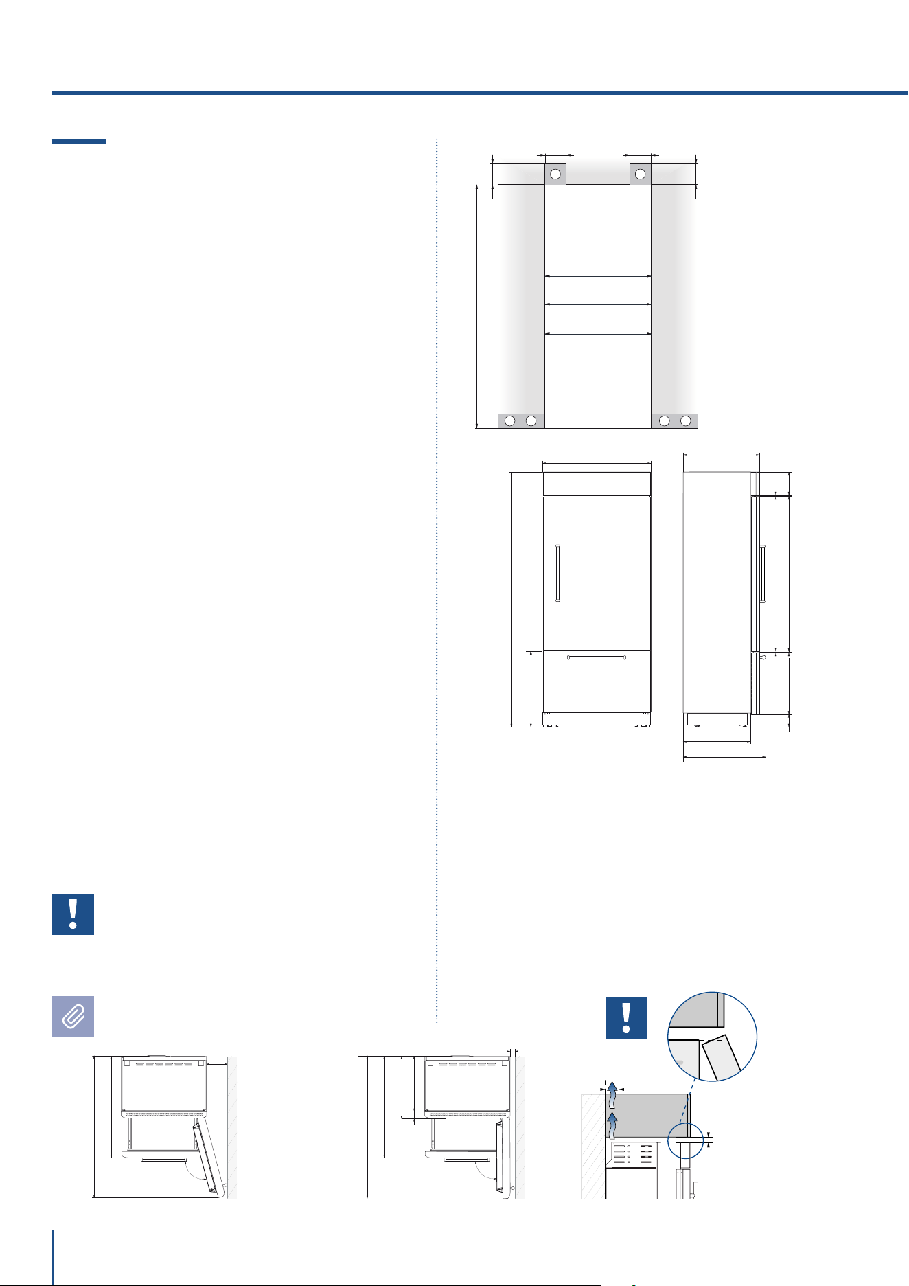
2.2 Installation niche features:
Integrated Series, 1T - 0T - 0H
Models
A - area to be left clear for the anti-tipping brackets
E - area to be left clear for the power supply cable
W - and water supply hose
Minimum Niche Height
2064 mm (81 1/4”)
Minimum Niche Depth
650 mm (25 5/8”)
Door Swing Clearance
S899: 1485 mm (58 1/2”)
S749: 1335 mm (52 5/8”)
S599: 1185 mm (46 5/8”)
Door Opening Angle
105°
Width
*
S899: 899 mm (35 3/8”)
S749: 749 mm (29 1/2”)
S599: 599 mm (23 5/8”)
Height
2050 mm (80 3/4”) + 25 mm (1”)
Depth with door (without panel)
610 mm (24”)
Minimum distance from the wall (hinge side)
with door at 105° and 90°, with 18mm (3/4”)
panel and handle h=58mm (2 1/4”).
S899: 220 mm (8 5/8”)
S749: 185 mm (7 1/4”)
S599: 150 mm (5 1/2”)
Dimensions in parentheses are in inches.
2. TECHNICAL REQUIREMENTS
105°
992 (39”)
560 (22”)
610 (24”)
S899: 899 (35 ⅜”)
S749: 749 (29 ½”)
S599: 599 (23 ⅝”)
10 (⅜”)
S899: 220 (8 ⅝”)
S749: 185 (7 ¼”)
S599: 150 (5 ½”)
90°
992 (39”)
S899: 1485 (58 ½”)
S749: 1335 (52 ⅝”)
S599: 1185 (46 ⅝”)
15 (¼”)
S899: 1485 (58 ½”)
S749: 1335 (52 ⅝”)
S599: 1185 (46 ⅝”)
105
°
992 (39”)
S749: 185 (7 ¼”)
90
°
992 (39”)
S749: 1335 (52 ⅝”)
15 (¼”)
S749: 1335 (52 ⅝”)
610 (24”)
560 (22”)
1293 (50 ⅞” )
474
(18 ⅝”)
231 (9
⅛”
) +
25 (1”)
517 (20 ⅜”)
248 (9
¾”
)
+ 25 (1”)
20 (¾”)
15 (⅝”)
721 (28 ⅜”) +25 (1”)
2050 (80 ¾”) +25 (1”)
1T/0T
*
2050 (80 ¾”) +25 (1”)
846 (33 ¼”) +25 (1”)
0H
*
610 (24”)
560 (22”)
517 (20 ⅜”)
231 (9
⅛”
) +
25 (1”)
248 (9
¾”
)
+ 25 (1”)
15 (⅝”)
20 (¾”)10 (⅜”)
1168(46”)
330
(13”)
259
(10
¼”
)
min 2064 (81 ¼”)
A A
E W E W
140 (5 ½”)140 (5 ½”)
100 (4”)
100 (4”)
S899: 900 (35 ½”)
S599: 600 (23 ¾”)
S749: 750 (29 ⅝”)
S899: 903 (35 ⅝”)
S599: 603 (23 ¾”)
S749: 753 (29 ¾”)
min 2064 (81 ¼”)
A A
E W E W
140 (5 ½”)140 (5 ½”)
100 (4”)
100 (4”)
S899: 900 (35 ½”)
min 2064 (81 ¼”)
A A
E W E W
140 (5 ½”)140 (5 ½”)
100 (4”)
100 (4”)
S749: 750 (29 ⅝”)
min 2064 (81 ¼”)
A A
E W E W
140 (5 ½”)140 (5 ½”)
100 (4”)
100 (4”)
S599: 600 (23 ¾”)
www.fhiaba.com · [email protected] · Info Line +39 0434 420160 www.fhiaba.com · [email protected] · Info Line +39 0434 420160
45
STANDARD NICHE WIDTH
MINIMUM NICHE WIDTH WITH
PORTAL
S899: 900 (35 1/2”) S899: 903 (35 3/8”)
S749: 750 (29 5/8”) S749: 753 (29 3/4”)
S599: 600 (23 3/4”) S599: 603 (23 7/8”)
S449: 450 (17 3/4”) S449: 453 (17 7/8”)
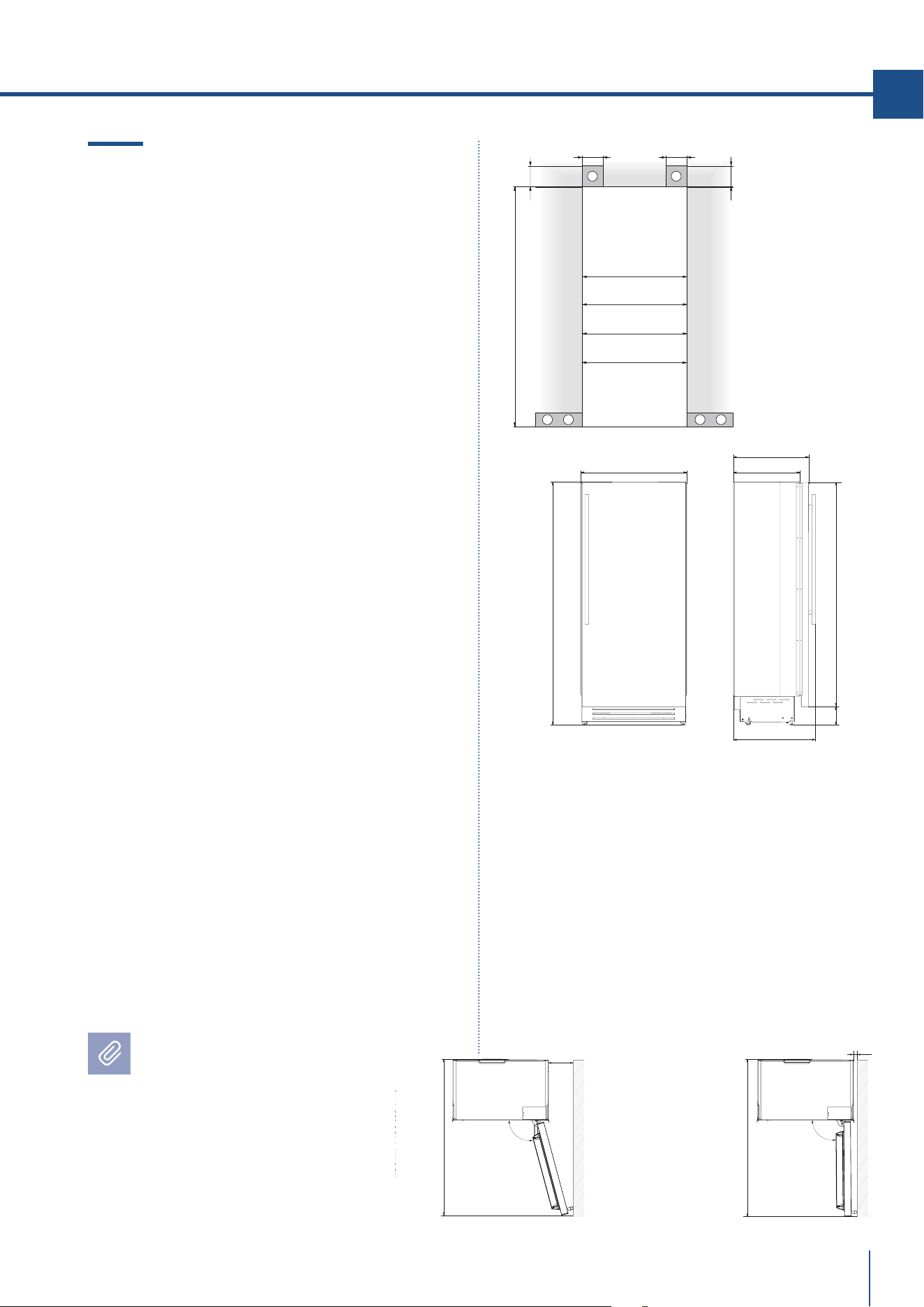
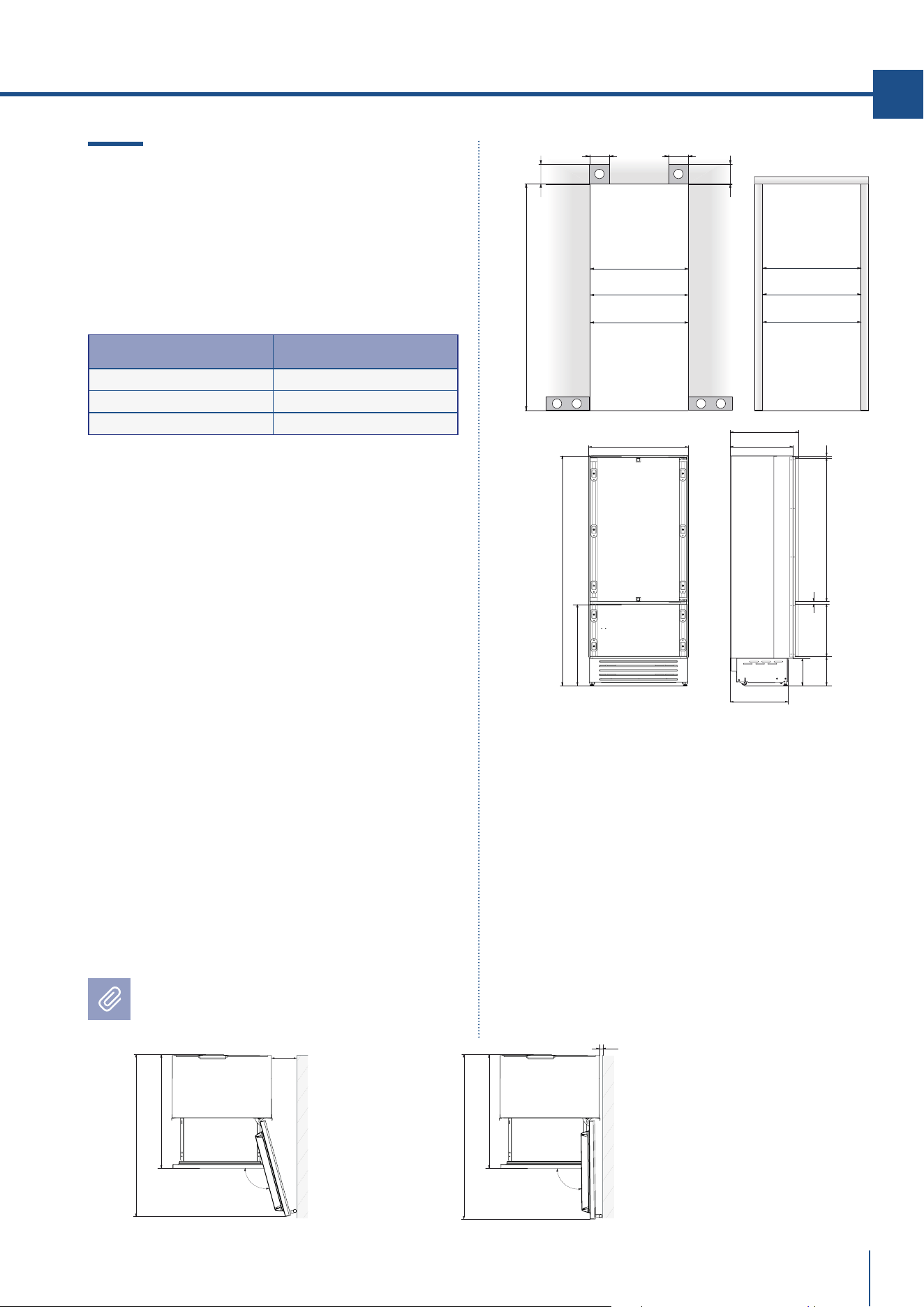
2.3 Installation niche features:
Integrated Series, 0F Column Models
A - area to be left clear for the anti-tipping brackets
E - area to be left clear for the power supply cable
W - and water supply hose
Minimum Niche Height
2064 mm (81 1/4”)
Minimum Niche Depth
650 mm (25 5/8”)
Door Swing Clearance
S899: 1490 mm (58 5/8”)
S749: 1340 mm (52 3/4”)
S599: 1190 mm (46 7/8”)
S449: 1040 mm (40 7/8”)
Door Opening Angle
105°
Width
*
S899: 899 mm (35 3/8”)
S749: 749 mm (29 1/2”)
S599: 599 mm (23 5/8”)
S449: 449 mm (17 5/8’’)
Height
2050 mm (80 3/4”) + 25 mm (1”)
Depth with door (without panel)
615 mm (24 1/4”)
Minimum distance from the wall (hinge side)
with door at 105° and 90°, with 18mm (3/4”)
panel and handle h=58mm (2 1/4”).
S899: 160 mm (6 1/4”)
S749: 125 mm (5”)
S599: 90 mm (3 1/2”)
S449: 50 mm (1 7/8”)
Dimensions in parentheses are in inches.
EN
615 (24 ¼” )
565 (22 ¼” )
1808 (71 ¼” )
231 (9
⅛”
)
+ 25 (1”)
11 (½”)
2050 (80 ¾”) +25 (1”)
0F *
min 2064 (81 ¼”)
A A
E W E W
140 (5 ½”) 140 (5 ½”)
100 (4”)
100 (4”)
S899: 900 (35 ½”)
S599: 600 (23 ¾”)
S449: 450 (17 ¾”)
S749: 750 (29 ⅝”)
522 (20 ½”)
S899: 903 (35 ⅝”)
S599: 603 (23 ⅞”)
S749: 753 (29 ¾”)
S449: 453 (17 ⅞”)
105
°
565 (22 ¼”)
615 (24 ¼”)
S899: 899 (35 ⅜”)
S749: 749 (29 ½”)
S599: 599 (23 ⅝”)
S449: 449 (17 ⅝”)
10 (⅜”)
S899: 220 (8 ⅝”)
S749: 185 (7 ¼”)
S599: 150 (5 ⅞”)
S449: 115 (4 ½”)
90
°
S899: 1490 (58 ⅝”)
S749: 1340 (52 ¾”)
S599: 1190 (46 ⅞”)
S449: 1040 (40 ⅞”)
S899: 1490 (58 ⅝”)
S749: 1340 (52 ¾”)
S599: 1190 (46 ⅞”)
S449: 1040 (40 ⅞”)
15 (6 ¼”)
565 (22 ¼”)
www.fhiaba.com · [email protected] · Info Line +39 0434 420160 www.fhiaba.com · [email protected] · Info Line +39 0434 420160
46
2. TECHNICAL REQUIREMENTS
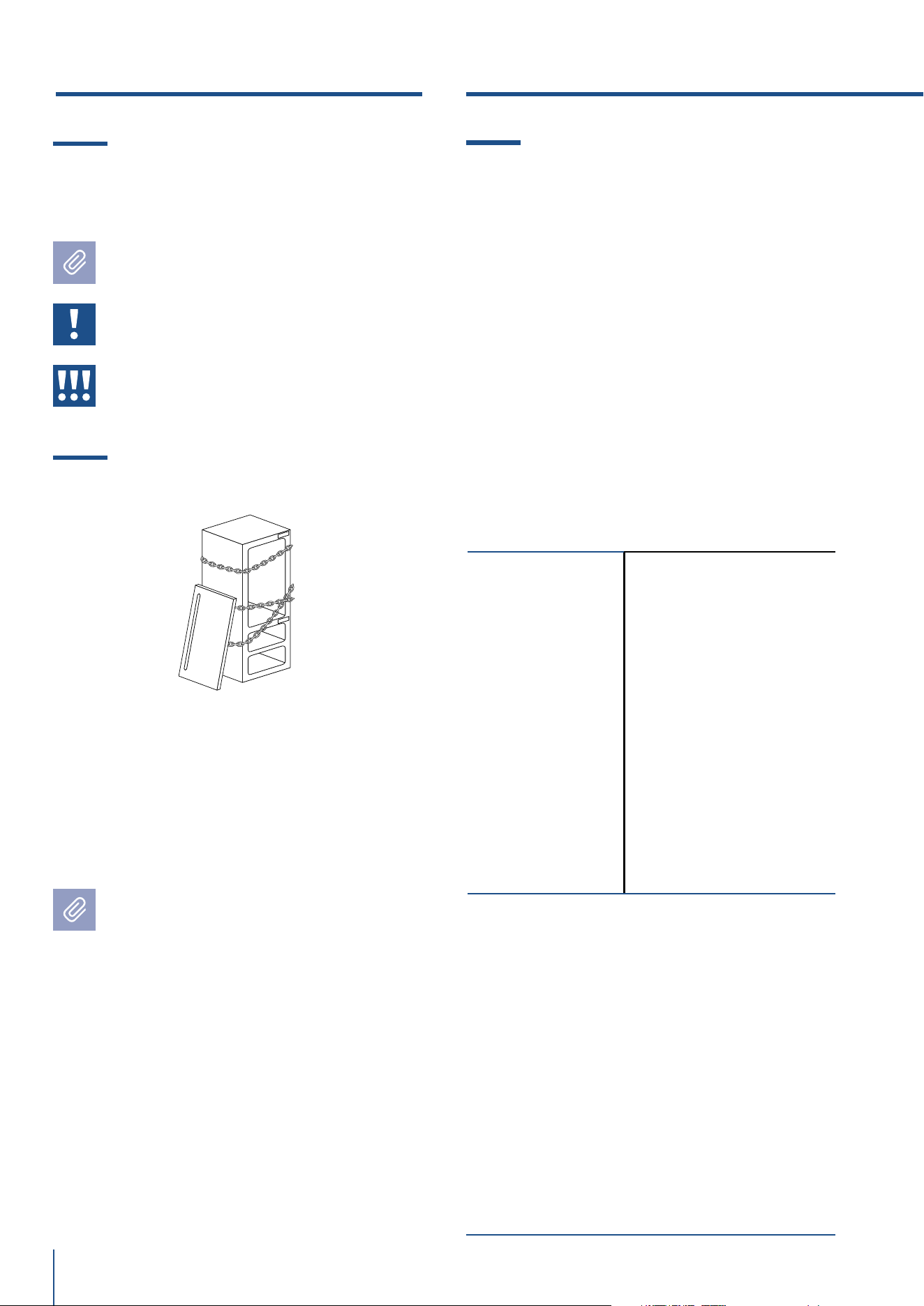
2.4 Installation niche features:
Classic Series, 1T - 0T - 0H Models
A - area to be left clear for the anti-tipping brackets
E - area to be left clear for the power supply cable
W - and water supply hose
Minimum Niche Height
2064 mm (81 1/4”)
Minimum Niche Width
KS899: 900 mm (35 1/2”)
KS749: 750 mm (29 5/8”)
KS599: 600 mm (23 3/4”)
Minimum Niche Depth
650 mm (25 5/8”)
Door Swing Clearance
KS899: 1475 mm (58 1/8”)
KS749: 1325 mm (52 1/8”)
KS599: 1175 mm (46 1/4”)
Door Opening Angle
105°
Width
*
KS899: 899 mm (35 3/8”)
KS749: 749 mm (29 1/2”)
KS599: 599 mm (23 5/8”)
Height
2050 mm (80 3/4”) + 25 mm (1”)
Depth with door
635 mm (25”)
Minimum distance from the wall (hinge side)
with door at 105° and 90°.
KS899: 230 mm (9”)
KS749: 195 mm (7 3/4”)
KS599: 160 mm (6 1/4”)
Dimensions in parentheses are in inches.
min 2064 (81 ¼”)
A A
E W E W
140 (5 ½”)140 (5 ½”)
100 (4”)
100 (4”)
KS899: 900 (35 ½”)
KS599: 600 (23 ¾”)
KS749: 750 (29 ⅝”)
635 (25”)
560 (22”)
1T/0T *
693 (27 ¼”)
2050 (80 ¾”) +25 (1”)
1308 (51 ½”)587 (23 ⅛”)
146 (5 ¾”)
+ 25(1”)
146 (5 ¾”)
+ 25(1”)
9 ( ⅜”)
732 (28 ⅞”)+25 (1”)
0H *
635 (25”)
560 (22”)
693 (27 ¼”)
2050 (80 ¾”) +25 (1”)
857 (33 ¾”) +25 (1”)
1185 (46 ⅝”)
342
(13 ½”)
362
(14 ¼”)
9 ( ⅜”)
6 ( ¼”)
1016 (40”)
560 (22”)
75 (3”)
XS899: 899 (35 ⅝”)
XS749: 749 (29 ½”)
XS599: 599 (23 ⅝”)
10 (⅜”)
58 (2 ¼”)
105°
635 (25”)
560 (22”)
75 (3”)
635 (25”)
KS899: 230 (9”)
KS749: 195 (7 ¾”)
KS599: 160 (6 ¼”)
KS899: 1475 (58 ⅛”)
KS749: 1325 (52 ⅛”)
KS599: 1175 (46 ¼”)
25 (1”)
90
°
58 (2 ¼”)
KS899: 1475 (58 ⅛”)
KS749: 1325 (52 ⅛”)
KS599: 1175 (46 ¼”)
www.fhiaba.com · [email protected] · Info Line +39 0434 420160 www.fhiaba.com · [email protected] · Info Line +39 0434 420160
47
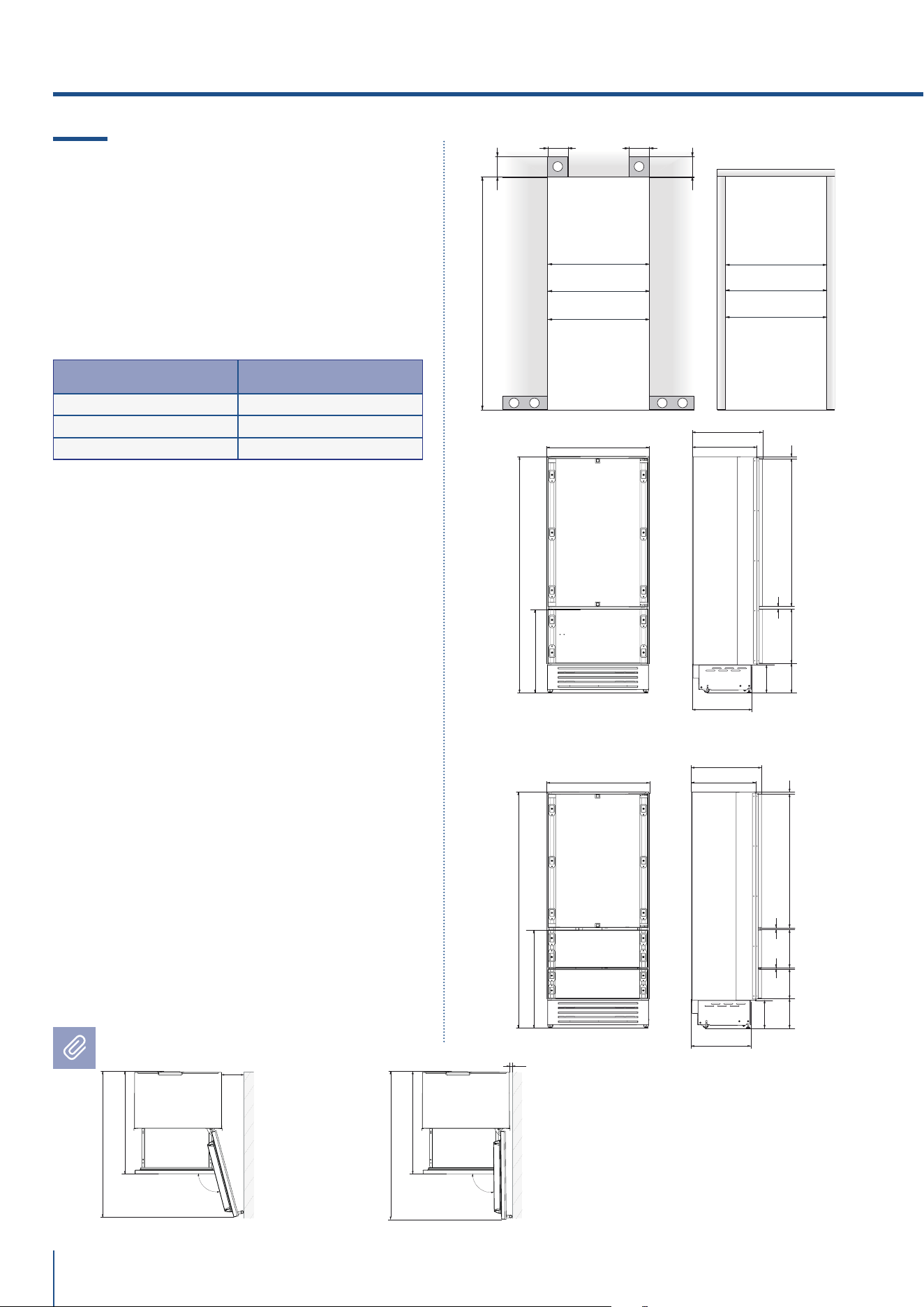
2.5 Installation niche features:
Classic Series, 0F Column Models
A - area to be left clear for the anti-tipping brackets
E - area to be left clear for the power supply cable
W - and water supply hose
Minimum Niche Height
2064 mm (81 1/4”)
Minimum Niche Width
KS899: 900 mm (35 1/2”)
KS749: 750 mm (29 5/8”)
KS599: 600 mm (23 3/4”)
KS449: 450 mm (17 3/4”)
Minimum Niche Depth
650 mm (25 5/8”)
Door Swing Clearance
KS899: 1480 mm (58 1/4”)
KS749: 1330 mm (52 3/8”)
KS599: 1180 mm (46 1/2”)
KS449: 1030 mm (40 1/2”)
Door Opening Angle
105°
Width *
KS899: 899 mm (35 3/8”)
KS749: 749 mm (29 1/2”)
KS599: 599 mm (23 5/8”)
KS449: 449 mm (17 5/8’’)
Height
2050 mm (80 3/4”) + 25 mm (1”)
Depth with door
640 mm (25 1/4”)
Minimum distance from the wall (hinge side)
with door at 105° and 90°.
KS899: 230 mm (9”)
KS749: 195 mm (7 3/4”)
KS599: 160 mm (6 1/4”)
KS449: 125 mm (4 7/8”)
Dimensions in parentheses are in
inches.
EN
min 2064 (81 ¼”)
A A
E W E W
140 (5 ½”) 140 (5 ½”)
100 (4”)
100 (4”)
KS899: 900 (35 ½”)
KS599: 600 (23 ¾”)
KS749: 750 (29 ⅝”)
640 (25 ¼” )
565 (22 ¼” )
0F
*
698 (27 ½”)
2050 (80 ¾”) +25 (1”)
1904 (75”)
146 (5 ¾”)
+ 25(1”)
KS449: 450 (17 ¾”)
105°
565 (22 ¼”)
640 (25 ¼”)
KS899: 899 (35 ⅜”)
KS749: 749 (29 ½”)
KS599: 599 (23 ⅝”)
KS449: 449 (17 ⅝”)
10 (⅜”)
75 (3”)
58 (2 ¼”)
KS899: 230 (9”)
KS749: 195 (7 ¾”)
KS599: 160 (6 ¼”)
KS449: 125 (4 ⅞”)
90
°
KS899: 1480 (58 ¼ ”)
KS749: 1330 (52 ⅜”)
KS599: 1180 (46 ½”)
KS 449: 1030 (40 ½’’)
25 (1”)
KS899: 1480 (58 ¼ ”)
KS749: 1330 (52 ⅜”)
KS599: 1180 (46 ½”)
KS 449: 1030 (40 ½’’)
www.fhiaba.com · [email protected] · Info Line +39 0434 420160 www.fhiaba.com · [email protected] · Info Line +39 0434 420160
48
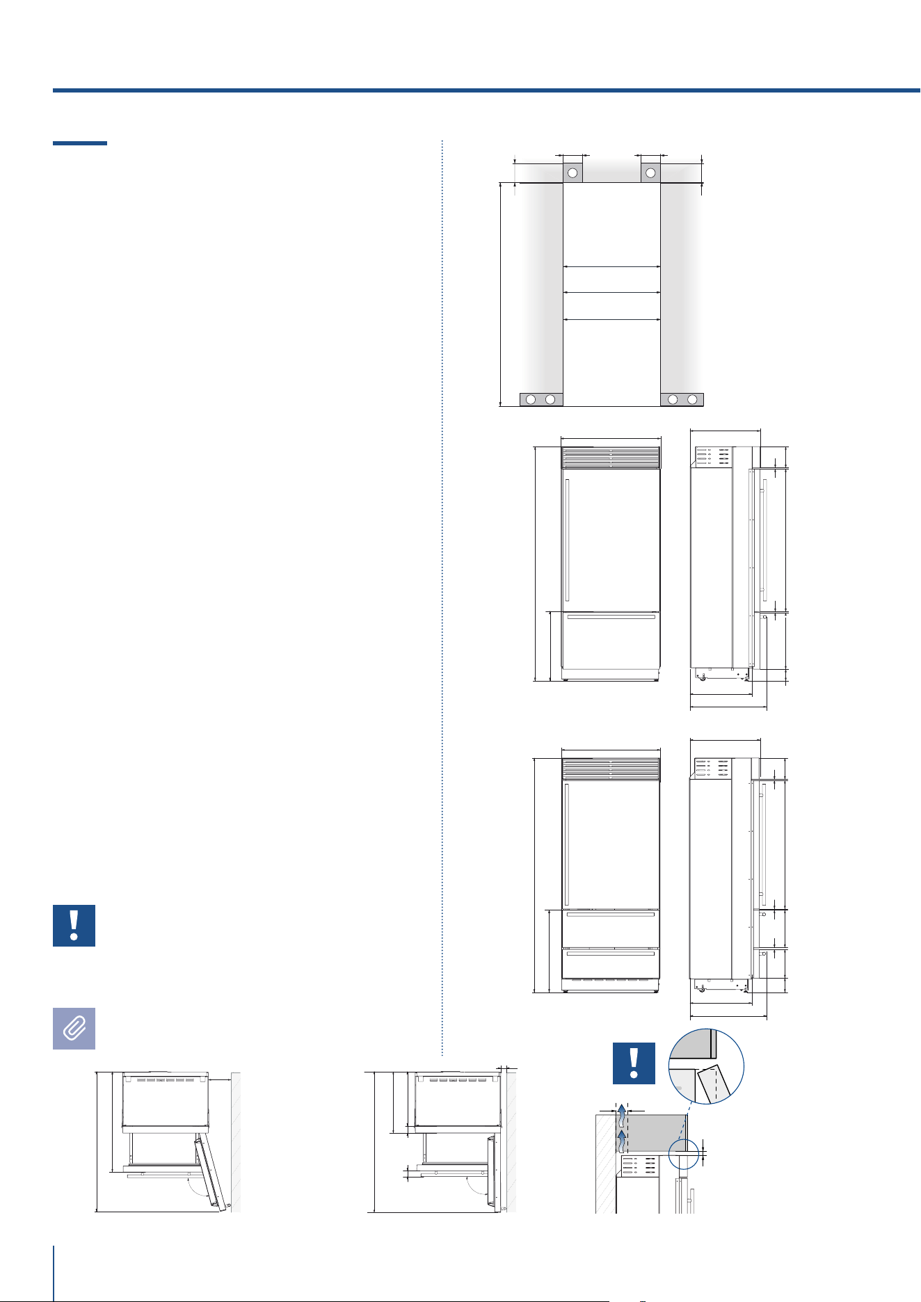
2.6 Installation niche features:
X-Pro Series
A - area to be left clear for the anti-tipping brackets
E - area to be left clear for the power supply cable
W - and water supply hose
Minimum Niche Height
2134 mm (84”)
Minimum Niche Width
XS899: 900 mm (35 1/2”)
XS749: 750 mm (29 5/8”)
XS599: 600 mm (23 3/4”)
Door Swing Clearance
XS899: 1475 mm (58 1/8”)
XS749: 1325 mm (52 1/8”)
XS599: 1175 mm (46 1/4”)
Door Opening Angle
105°
Width
XS899: 899 mm (35 3/8”)
XS749: 749 mm (29 1/2”)
XS599: 599 mm (23 5/8”)
Height
2120 mm (83 1/2”) + 25 mm (1”)
Depth with door
635 mm (25 ”)
Minimum distance from the wall (hinge side)
with door at 105° and 90°.
XS899: 230 mm (9”)
XS749: 195 mm (7 3/4”)
XS599: 160 mm (6 1/4”)
Important!
If the units are to be installed inside a
niche or within an enclosed structure, it
is necessary to design a ventilation shaft
at the back of the niche to assure proper
ventilation at the back of the unit.
Dimensions in parentheses are in inches.
2. TECHNICAL REQUIREMENTS
A A
E W E W
140 (5 ½”)140 (5 ½”)
100 (4”)
100 (4”)
min 2134 (84”)
XS899: 900 (35 ½”)
XS599: 600 (23 ¾”)
XS749: 750 (29 ⅝”)
560 (22”)
2120 (83 ½”) +25 (1”)
613 (24 ⅛”)+25 (1”)
2120 (83 ½”) +25 (1”)
635 (25”)
693 (27 ¼”)
516 (20 ⅜”)
1296 (50”)
195 (7 ⅝”)
8 (⅜”)
8 (⅜”)
195 (7 ⅝”)
8 (⅜”)
8 (⅜”)
560 (22”)
635 (25”)
693 (27 ¼”)
749 (29 ½”) + 25 (1”)
1170 (46”)343 (13 ½”)293
(11 ½”)
6 ( ¼”)
1T/0T
0H
*
97 (3 ⅞”)
+ 25 (1”)
97 (3 ⅞”)
+ 25 (1”)
*
min 10 (⅜”)
min 50 (2”)
1016 (40”)
560 (22”)
75 (3”)
XS899: 899 (35 ⅝”)
XS749: 749 (29 ½”)
XS599: 599 (23 ⅝”)
10 (⅜”)
58 (2 ¼”)
105
°
635 (25”)
560 (22”)
75 (3”)
635 (25”)
XS899: 230 (9”)
XS749: 195 (7 ¾”)
XS599: 160 (6 ¼”)
XS899: 1475 (58 ⅛”)
XS749: 1325 (52 ⅛”)
XS599: 1175 (46 ¼”)
25 (1”)
90
°
58 (2 ¼”)
XS899: 1475 (58 ⅛”)
XS749: 1325 (52 ⅛”)
XS599: 1175 (46 ¼”)
www.fhiaba.com · [email protected] · Info Line +39 0434 420160 www.fhiaba.com · [email protected] · Info Line +39 0434 420160
49
min 10 (⅜”)
min 50 (2”)
A A
E W E W
140 (5 ½”) 140 (5 ½”)
100 (4”)
100 (4”)
min 2134 (84”)
XS899: 900 (35 ½”)
XS599: 600 (23 ¾”)
XS749: 750 (29 ⅝”)
560 (22”)
2120 (83 ½”) +25 (1”)
640 (25 ¼”)
693 (27 ¼”)
1820 (71 ⅝”)
195 (7 ⅝”)
8 (⅜”)
0F *
97 (3 ⅞”)
+ 25 (1”)
XS449: 450 (17 ¾”)
EN
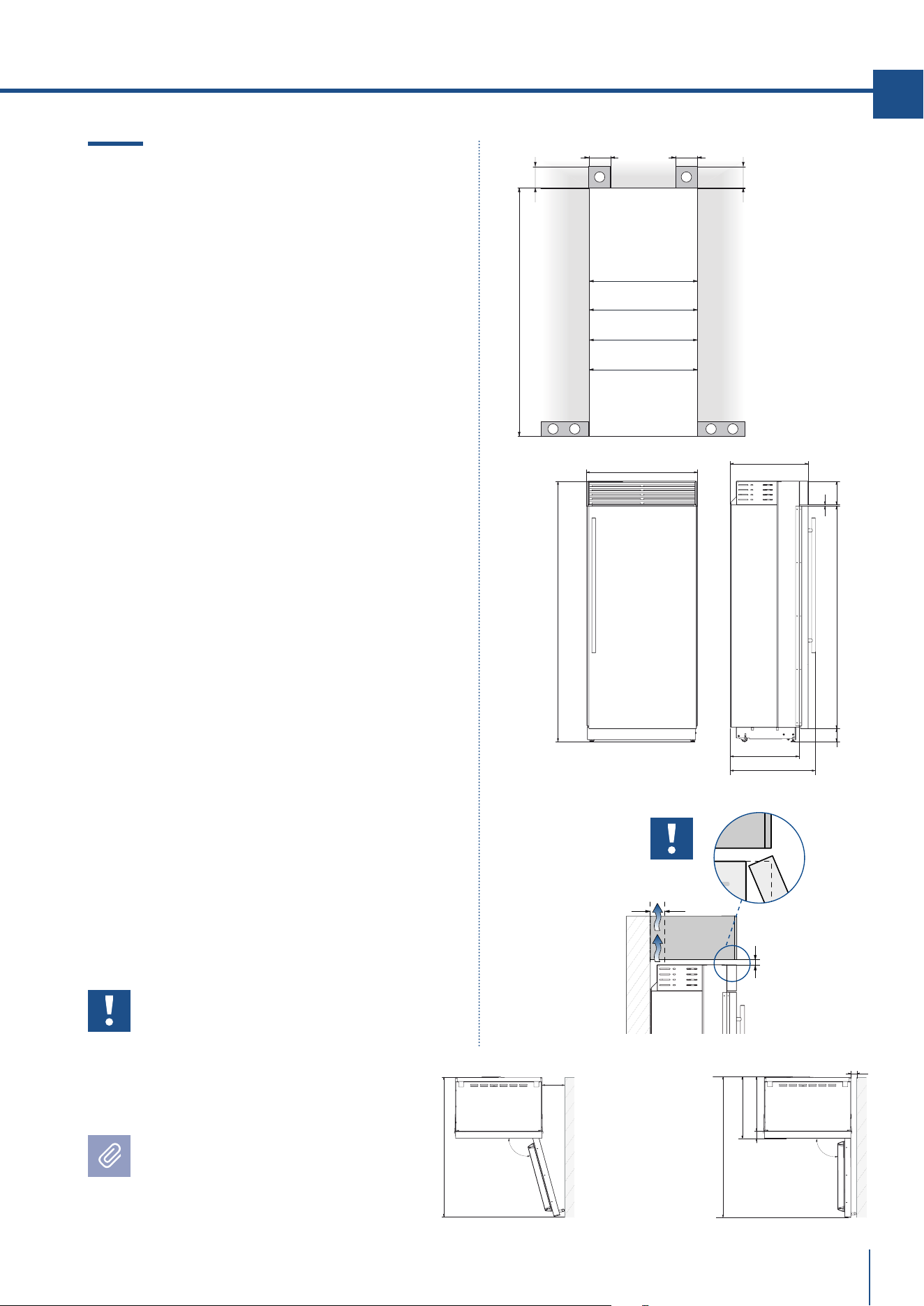
2.7 Installation niche features:
X-Pro Series: - 0F Column Models
A - area to be left clear for the anti-tipping brackets
E - area to be left clear for the power supply cable
W - and water supply hose
Minimum Niche Height
2134 mm (84”)
Minimum Niche Width
XS899: 900 mm (35 1/2”)
XS749: 750 mm (29 5/8”)
XS599: 600 mm (23 3/4”)
XS449: 450 mm (17 3/4”)
Door Swing Clearance
XS899: 1480 mm (58 1/4”)
XS749: 1330 mm (52 3/8”)
XS599: 1180 mm (46 1/2”)
XS449: 1030 mm (40 1/2”)
Door Opening Angle
105°
Width
XS899: 899 mm (35 3/8”)
XS749: 749 mm (29 1/2”)
XS599: 599 mm (23 5/8”)
XS449: 449 mm (17 5/8”)
Height
2120 mm (83 1/2”) + 25 mm (1”)
Depth with door
640 mm (25 1/4”)
Minimum distance from the wall (hinge side)
with door at 105° and 90°.
XS899: 230 mm (9”)
XS749: 195 mm (7 3/4”)
XS599: 160 mm (6 1/4”)
XS449: 125 mm (4 7/8”)
Important!
If the units are to be installed
inside a niche or within an
enclosed structure, it is necessary
to design a ventilation shaft
at the back of the niche to
assure proper ventilation
at the back of the unit.
Dimensions in parentheses
are in inches.
560 (22”)
75 (3”)
XS899: 899 (35 ⅝”)
XS749: 749 (29 ½”)
XS599: 599 (23 ⅝”)
XS449: 449 (17 ⅝”)
10 (⅜”)
58 (2 ¼”)
105
°
635 (25”)
XS899: 230 (9”)
XS749: 195 (7 ¾”)
XS599: 160 (6 ¼”)
XS449: 125 (4 ⅞”)
XS899: 1475 (58”)
XS749: 1325 (52 ⅛”)
XS599: 1175 (46 ¼”)
XS449: 1025 (40 ⅜”)
90
°
XS899: 230 (9”)
XS749: 195 (7 ¾”)
XS599: 160 (6 ¼”)
XS449: 125 (4 ⅞”)
560 (22”)
75 (3”)
635 (25”)
XS899: 1480 (58 ¼”)
XS749: 1330 (52 ⅜”)
XS599: 1180 (46 ½”)
XS449: 1030 (40 ½”)
25 (1”)
90
°
XS899: 1480 (58 ¼”)
XS749: 1330 (52 ⅜”)
XS599: 1180 (46 ½”)
XS449: 1030 (40 ½”)
www.fhiaba.com · [email protected] · Info Line +39 0434 420160 www.fhiaba.com · [email protected] · Info Line +39 0434 420160
50
2.8 Installation niche features:
Country Series
A - area to be left clear for the anti-tipping brackets
E - area to be left clear for the power supply cable
W - and water supply hose
Minimum Niche Height
2134 mm (84”)
Minimum Niche Width
AS899: 900 mm (35 1/2”)
AS749: 750 mm (29 5/8”)
AS599: 600 mm (23 3/4”)
Door Swing Clearance
AS899: 1475 mm (58 1/8”)
AS749: 1325 mm (52 1/8”)
AS599: 1175 mm (46 1/4”)
Door Opening Angle
105°
Width
AS899: 887 mm (35”)
AS749: 737 mm (29”)
AS599: 587 mm (23 1/8”)
Height
2120 mm (83 1/2”) + 25 mm (1”)
Depth with door
635 mm (25 ”)
Minimum distance from the wall (hinge side)
with door at 105° and 90°.
AS899: 230 mm (9”)
AS749: 195 mm (7 3/4”)
AS599: 160 mm (6 1/4”)
Important!
If the units are to be installed inside a
niche or within an enclosed structure, it
is necessary to design a ventilation shaft
at the back of the niche to assure proper
ventilation at the back of the unit.
Dimensions in parentheses are in inches.
2. TECHNICAL REQUIREMENTS
A A
E W E W
140 (5 ½”)140 (5 ½”)
100 (4”)
100 (4”)
min 2134 (84”)
AS899: 900 (35 ½”)
AS599: 600 (23 ¾”)
AS749: 750 (29 ⅝”)
560 (22”)
2120 (83 ½”) +25 (1”)
613 (24 ⅛”)+25 (1”)
635 (25”)
695 (27 ¼”)
485 (19 ⅛”)
1296 (50”)
195 (7 ⅝”)
8 (⅜”)
8 (⅜”)
1T/0T *
128 (5)
+ 25 (1”)
min 10 (⅜”)
min 50 (2”)
105
°
1016 (40”)
560 (22”)
75 (3”)
AS899: 887 (35”)
AS749: 737 (29”)
AS599: 587 (23 ⅛”)
10 (⅜”)
60 (2 ¼”)
635 (25”)
AS899: 230 (9”)
AS749: 195 (7 ¾”)
AS599: 160 (6 ¼”)
560 (22”)
75 (3”)
AS899: 887 (35”)
AS749: 737 (29”)
AS599: 587 (23 ⅛”)
10 (⅜”)
60 (2 ¼”)
635 (25”)
1016 (40”)
AS899: 1475 (58 ¼”)
AS749: 1325 (52 ⅛”)
AS599: 1175 (46 ¼”)
AS899: 1475 (58 ¼”)
AS749: 1325 (52 ⅛”)
AS599: 1175 (46 ¼”)
90°
25 (1”)
www.fhiaba.com · [email protected] · Info Line +39 0434 420160 www.fhiaba.com · [email protected] · Info Line +39 0434 420160
EN
51
STANDARD NICHE WIDTH
MINIMUM NICHE WIDTH WITH
PORTAL
BS899: 900 (35 1/2”) BS899: 903 (35 3/8”)
BS749: 750 (29 5/8”) BS749: 753 (29 3/4”)
BS599: 600 (23 3/4”) BS599: 603 (23 7/8”)
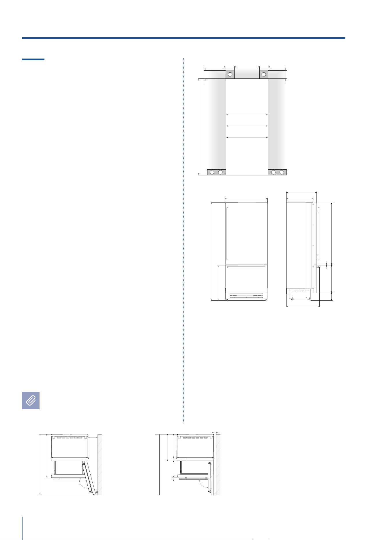
2.9 Installation niche features:
Brilliance-Integrated Series
A - area to be left clear for the anti-tipping brackets
E - area to be left clear for the power supply cable
W - and water supply hose
Minimum Niche Height
2064 mm (81 1/4”)
Minimum Niche Depth
650 mm (25 5/8”)
Door Swing Clearance
BS899: 1485 mm (58 1/2”)
BS749: 1335 mm (52 5/8”)
BS599: 1185 mm (46 5/8”)
Door Opening Angle
105°
Width
*
BS899: 899 mm (35 3/8”)
BS749: 749 mm (29 1/2”)
BS599: 599 mm (23 5/8”)
Height
2050 mm (80 3/4”) + 25 mm (1”)
Depth with door (without panel)
610 mm (24”)
Minimum distance from the wall (hinge side)
with door at 105° and 90°, with 18mm (3/4”)
panel and handle h=58mm (2 1/4”).
BS899: 220 mm (8 5/8”)
BS749: 185 mm (7 1/4”)
BS599: 150 mm (5 1/2”)
Dimensions in parentheses are in inches.
105
°
992 (39”)
560 (22”)
610 (24”)
S899: 899 (35 ⅜”)
S749: 749 (29 ½”)
S599: 599 (23 ⅝”)
10 (⅜”)
BS899: 220 (8 ⅝”)
BS749: 185 (7 ¼”)
BS599: 150 (5 ½”)
90
°
992 (39”)
BS899: 1485 (58 ½”)
BS749: 1335 (52 ⅝”)
BS599: 1185 (46 ⅝”)
15 (¼”)
BS899: 1485 (58 ½”)
BS749: 1335 (52 ⅝”)
BS599: 1185 (46 ⅝”)
610 (24”)
560 (22”)
1293 (50 ⅞” )
474
(18 ⅝”)
231 (9
⅛”
) +
25 (1”)
500 (19 ¾”)
248 (9
¾”
)
+ 25 (1”)
20 (¾”)
15 (⅝”)
721 (28 ⅜”) +25 (1”)
2050 (80 ¾”) +25 (1”)
0T
*
min 2064 (81 ¼”)
A A
E W E W
140 (5 ½”) 140 (5 ½”)
100 (4”)
100 (4”)
BS899: 900 (35 ½”)
BS599: 600 (23 ¾”)
BS749: 750 (29 ⅝”)
min 2064 (81 ¼”)
A A
E W E W
140 (5 ½”) 140 (5 ½”)
100 (4”)
100 (4”)
BS899: 900 (35 ½”)
min 2064 (81 ¼”)
A A
E W E W
140 (5 ½”) 140 (5 ½”)
100 (4”)
100 (4”)
BS749: 750 (29 ⅝”)
min 2064 (81 ¼”)
A A
E W E W
140 (5 ½”) 140 (5 ½”)
100 (4”)
100 (4”)
BS599: 600 (23 ¾”)
615 (24¼” )
560 (22”)
1808 (71 ¼” )
231 (9
1⁄8”
) +
25 (1”)
500 (19 ¾”)
233 (9
¼”
)
+ 25 (1”)
15 (5⁄8”)
2050 (80 ¾”) +25 (1”)
0F
S899: 903 (35 ⅝”)
S599: 603 (23 ⅞”)
S749: 753 (29 ¾”)
www.fhiaba.com · [email protected] · Info Line +39 0434 420160 www.fhiaba.com · [email protected] · Info Line +39 0434 420160
52
2.10 Installation niche features:
Brilliance-Classic Series
A - area to be left clear for the anti-tipping brackets
E - area to be left clear for the power supply cable
W - and water supply hose
Minimum Niche Height
2064 mm (81 1/4”)
Minimum Niche Width
BKS899: 900 mm (35 1/2”)
BKS749: 750 mm (29 5/8”)
BKS599: 600 mm (23 3/4”)
Minimum Niche Depth
650 mm (25 5/8”)
Door Swing Clearance
BKS899: 1475 mm (58 1/8”)
BKS749: 1325 mm (52 1/8”)
BKS599: 1175 mm (46 1/4”)
Door Opening Angle
105°
Width
BKS899: 899 mm (35 3/8”)
BKS749: 749 mm (29 1/2”)
BKS599: 599 mm (23 5/8”)
Height
2050 mm (80 3/4”) + 25 mm (1”)
Depth with door
635 mm (25’’)
Minimum distance from the wall (hinge side)
with door at 105° and 90°.
BKS899: 230 mm (9”)
BKS749: 195 mm (7 3/4”)
BKS599: 160 mm (6 1/4”)
Dimensions in parentheses are in inches.
2. TECHNICAL REQUIREMENTS
1016 (40”)
560 (22”)
75 (3”)
XS899: 899 (35 ⅝”)
XS749: 749 (29 ½”)
XS599: 599 (23 ⅝”)
10 (⅜”)
58 (2 ¼”)
105
°
635 (25”)
560 (22”)
75 (3”)
635 (25”)
BKS899: 230 (9”)
BKS749: 195 (7 ¾”)
BKS599: 160 (6 ¼”)
BKS899: 1475 (58 ⅛”)
BKS749: 1325 (52 ⅛”)
BKS599: 1175 (46 ¼”)
25 (1”)
90
°
58 (2 ¼”)
BKS899: 1475 (58 ⅛”)
BKS749: 1325 (52 ⅛”)
BKS599: 1175 (46 ¼”)
A A
E W E W
140 (5 ½”) 140 (5 ½”)
100 (4”)
100 (4”)
min 2064 (81 ¼”)
BKS899: 900 (35 ½”)
BKS599: 600 (23 ¾”)
BKS749: 750 (29 ⅝”)
635 (25”)
560 (22”)
0T
*
693 (27 ¼”)
2050 (80 ¾”) +25 (1”)
1308 (51 ½”)587 (23 ⅛”)
146 (5 ¾”)
+ 25(1”)
9 ( ⅜”)
732 (28 ⅞”)+25 (1”)
www.fhiaba.com · [email protected] · Info Line +39 0434 420160 www.fhiaba.com · [email protected] · Info Line +39 0434 420160
53
EN
3.1 Transport to installation site
and unpacking
The appliance is very heavy.
Take maximum care during handling
to avoid injury.
The appliance should always be
transported in an erect position.
Avoid at all costs leaning it on its front
side.
Since this is a large and heavy appliance, before trans-
porting the appliance, check the access to the loca-
tion where it will be installed (door size, manoeuvring
space in stairwells, etc.).
The appliance is attached to the base of the packaging
(pallet) through four bolts which can be removed us-
ing a 17 mm (3/4”) wrench.
It is recommended to use a manual transporting de-
vice to move the appliance to the installation site, and
only at this point to remove the base of the packaging.
The appliance should always be transported in an
erect position.
If this is not possible, transport the appliance laying
on its rear side.
Once at the installation site, the appliance, which is
equipped with four wheels, can be taken o the pallet
and positioned in the installation area.
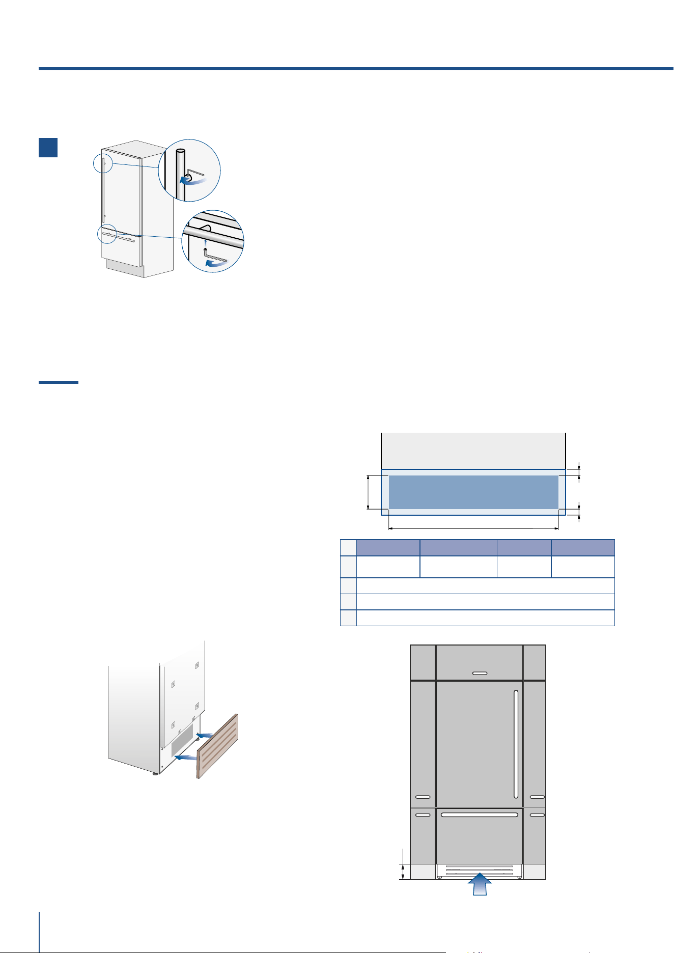
Operate as follows:
> Take o the four boltshsecuring the appliance to the
pallet by means of a 17 mm (3/4”) open spanner.
> Remove the fixing brackets [ 3 ] and [ 4 ] .
> To remove the front fixing bracket [ 3 ] , unscrew for
one or two turns the rear wheel adjusting bolt [ 2 ] by
means of a 13 mm (1/2”) box spanner, avoiding too
much strenght while thightening the nut, which could
damage the leveling feet adjusting system.
> From the back of the unit and by means of a suit-
able, high duty hand trolley, take o the appliance and
place it on the floor.
Be very careful to avoid any damage to floors. Delicate
floors should be protected with plywood, hard card-
board or similar material panels.
3. PREPARING THE INSTALLATION
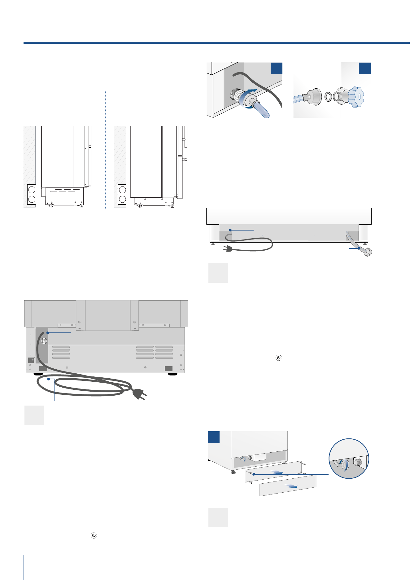
3.2 Electrical and Water connection
The Built-in Fhiaba filter cannot make it
safe to drink any water which is not suit-
able for human consumption.
The appliance should be connected only
to a drinkable water supply system.
Do not use extension cords or adapters.
Once the appliance has been connected to
the water system, turn the Ice Maker
off (touch the button
on control panel
to switch it off) before the main water is
shut off.
A Schuko 16 A socket with an ecient grounding
should be made available for the electrical mains con-
nection, as well as an omnipolar
switch which can easily be reached when the appli-
ance is installed.
To connect to the water supply system (for appliances
equipped with ice makers) a tap with a male 3/4” con-
nection should be provided, which must also be easily
accessible once the appliance is installed.
The appliance is provided with a water supply hose
and seal kit which is suitable for high water pressure
and complies the Food Regulations.
The water filter cartridge, which is provided with the
appliance, should be installed according to the ac-
companying instructions.
Use only the new hose and the new gaskets which
are supplied with the appliance. Discard any hose and
gasket which may have already been installed.
Electrical cord length: 2,0 mt (78 3/4”)
Water connection line length: 2,5 mt (98 3/8”)
1
4
1
2
3
EW
E W
EW
E W
www.fhiaba.com · [email protected] · Info Line +39 0434 420160 www.fhiaba.com · [email protected] · Info Line +39 0434 420160
54
INTEGRATED AND CLASSIC SERIES:
Operate as follows:
> Unwind the electric cable and connect it directly to
the wall socket.
> Make sure the appliance is in the Stand-by con-
dition and that all lights are o; should it be not so
press the Unit button
to switch it o.
ELECTRICAL AND WATER SUPPLY BEHIND THE UNIT
Back of appliance
INTEGRATED AND
CLASSIC SERIES:
X-PRO AND COUNTRY
SERIES:
> Fit one end of the water hose onto the connector at
the appliance’s back, using the supplied 3/4” fitting
[ 1 ] .
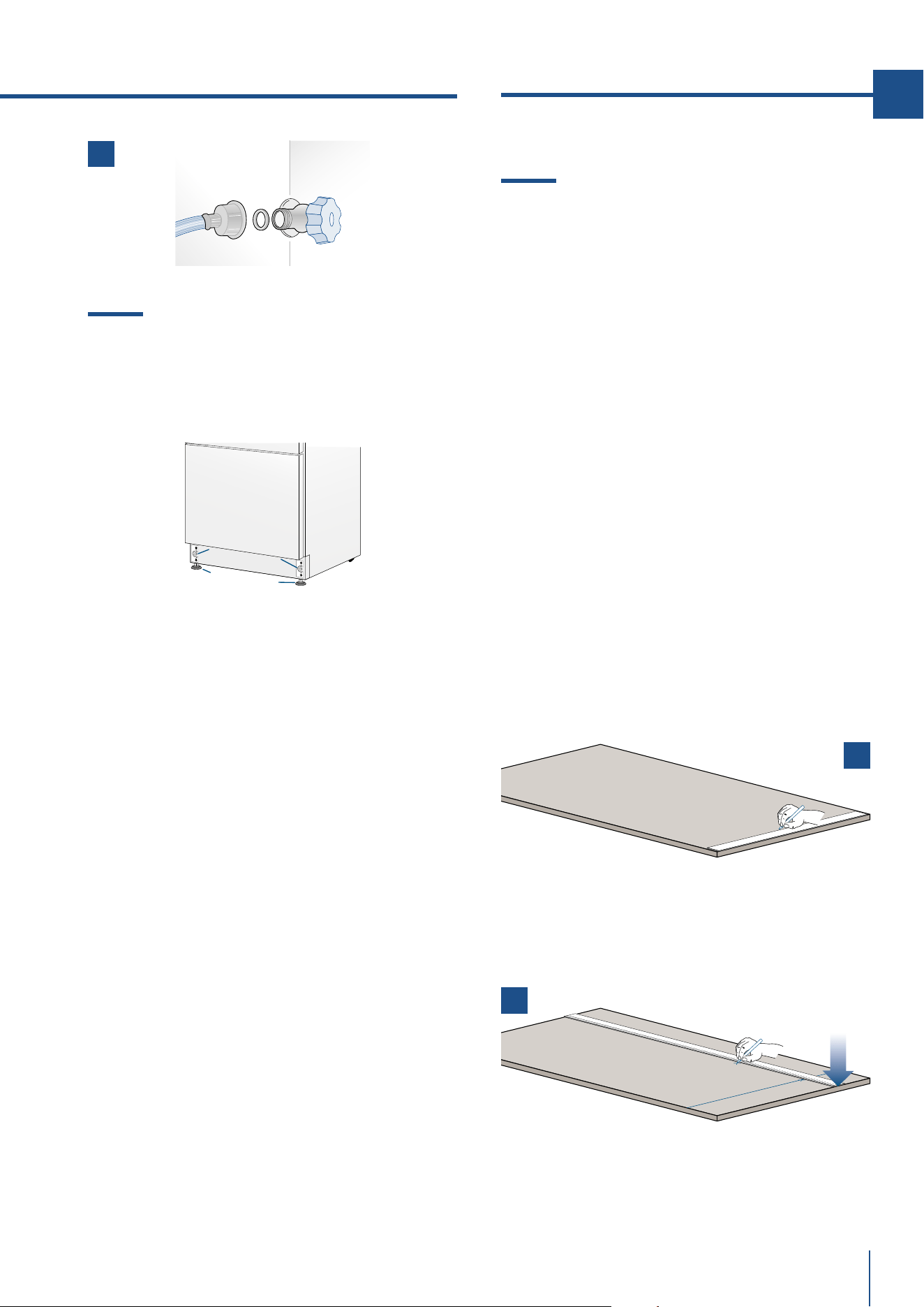
> Fit the other end of the hose to the water tap, using
the supplied 3/4” fitting [ 2 ].
> On 0FZ models only, install the water filter support
outside the appliance, using the fittings supplied (see
page 49).
X-PRO AND COUNTRY SERIES:
Operate as follows:
> Unwind the electric cable and connect it directly to
the wall socket.
> Make sure the appliance is in the Stand-by con-
dition and that all ights are o; should it be not so
press the Unit button
to switch it o.
> Connect the water pipe to the threaded connection
located at the base of the appliance [ 1 ], using the
3/4” fitting supplied.
> Connect the hose to the tap using the 3/4” fitting
supplied [ 2 ].
> Only on 0FZ models, install the water filter support
externally to the appliance, using the fittings sup-
plied (see page 49).
Back of appliance
Front of appliance
3. PREPARING THE INSTALLATION
E
W
E
W
Water connection
Electrical connection
Electrical connection
Water connection
1
1 2
www.fhiaba.com · [email protected] · Info Line +39 0434 420160 www.fhiaba.com · [email protected] · Info Line +39 0434 420160
55
EN
3.3 Levelling
Adjust the appliance level by means of the front
levelling feet and the rear adjustable wheels.
Operate as follows:
> After removing the bottom plinth or grille (it is
kept in position by magnets), adjust the height of
the levelling feet [ 1 ] by means of a 17 mm (3/4”)
open spanner.
> Then adjust the height of the rear wheels by
turning the front adjusting bolts [ 2 ] clockwise or
anticlockwise as it may be required.
> Remount the bottom plinth or grille.
INTEGRATED SERIES
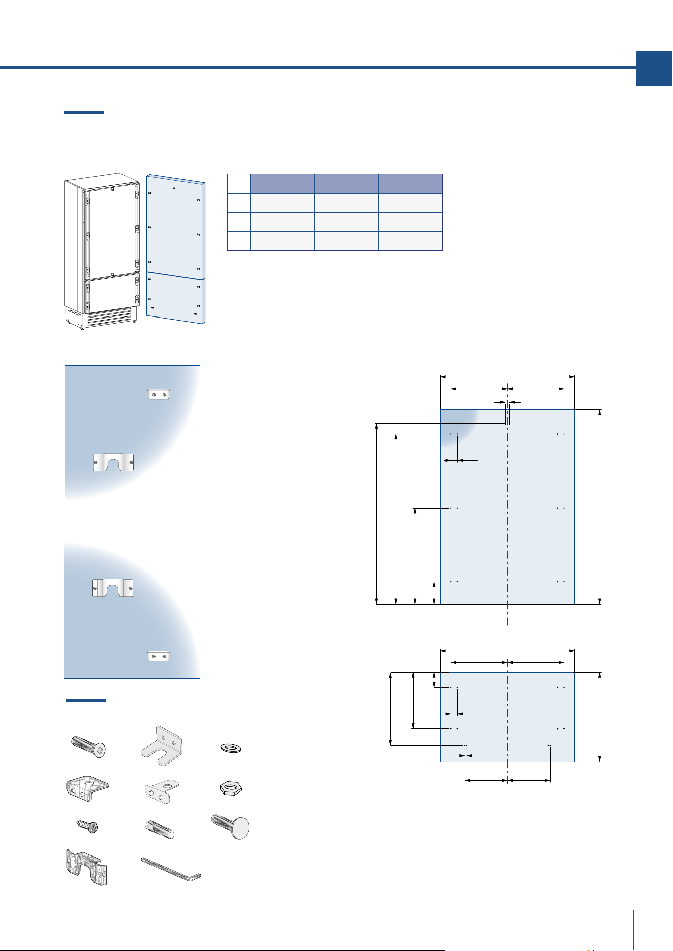
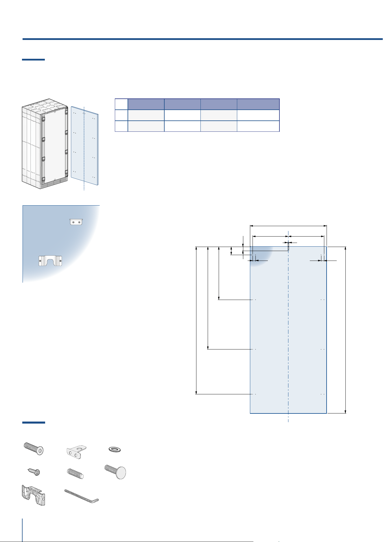
4.1 Decorative door and bottom-drawer
panels layout
The dimensions of the panels are indicated in the
table and drawings on next pages.
Nevertheless, according to the requirements for
aligning with other kitchen structures, the door
panel can be higher than the upper edge of the
refrigerator door, and the drawer panel can be
lower than the edge of the drawer.
The panels must be mounted using special bra-
ces which attach to adjustable devices provided
on the door and drawer and with brackets that
anchor and adjust the panel’s vertical direction.
Braces, brackets and fixing screws are provided
with the appliance and must be applied to the pa-
nel as indicated.
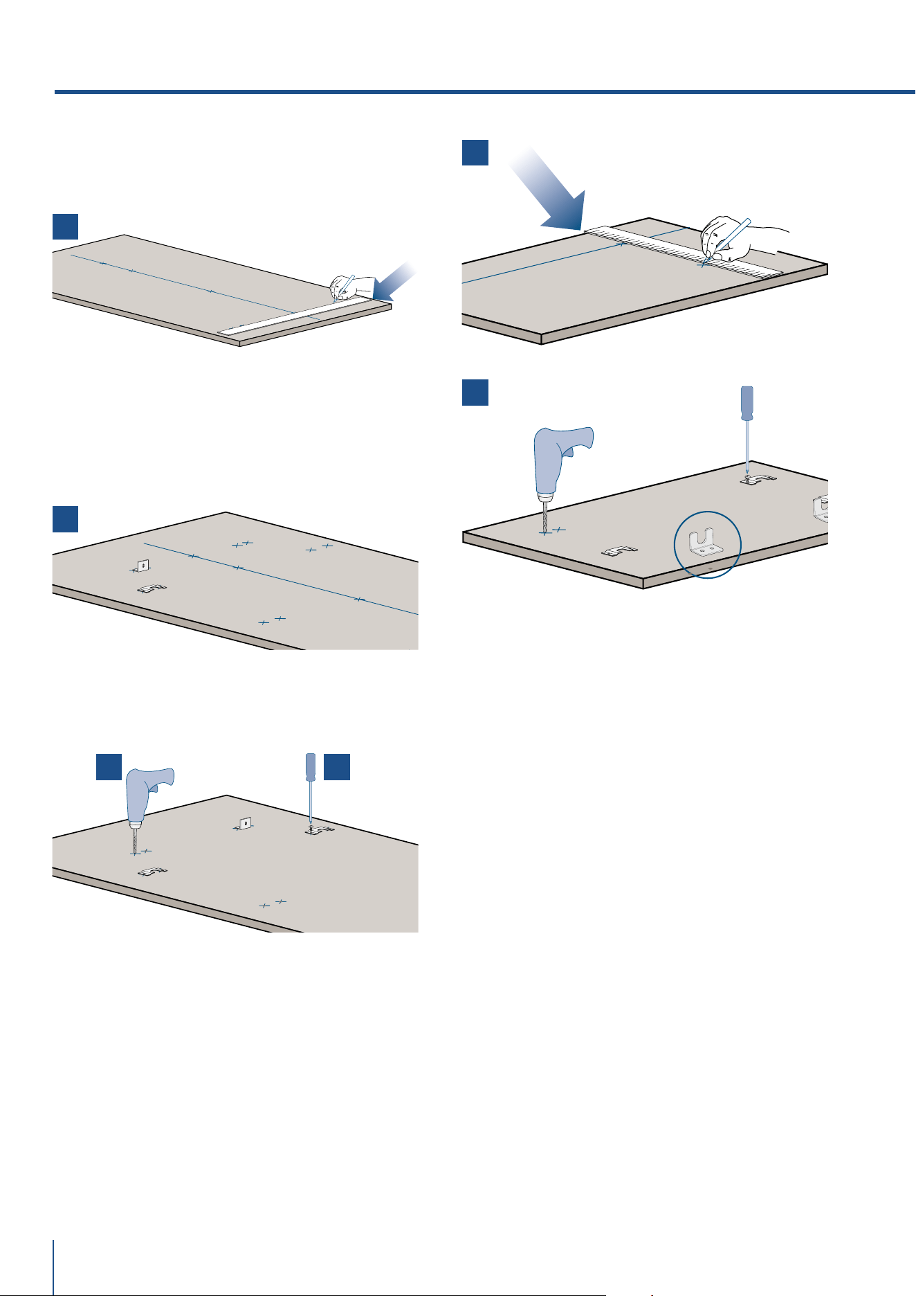
Operate as follows:
To prepare the panels to be mounted on the ap-
pliance, follow these steps, working on the back
of the panel.
Door Panel
> Trace, a line dividing the panel width in half [ 1 ].
> Starting form the Bottom edge of the panel,
mark the positioning of the brackets [ 2 ].
4. PANELS MOUNTING
1
2
1
2
2
1
2
www.fhiaba.com · [email protected] · Info Line +39 0434 420160 www.fhiaba.com · [email protected] · Info Line +39 0434 420160
56
> Following the corresponding table, mark the
external and then the internal hole [ 3 ].
> Position the brackets on each set of marks to
make sure they are aligned [ 4 ], then drill holes
through the panel (pay close attention to the pa-
nel’s thickness) [ 5 ].
> Screw the brackets in place [ 6 ].
Drawer Panel
> When preparing the Drawer Panel, follow the
same instructions as per the door panel, but
make sure measurements are taken starting
from the top edge [ 7 ].
The support bracket faces the opposite way [ 8 ]
(note imgs 4 and 8).
4. PANELS MOUNTING
8
7
65
4
3
www.fhiaba.com · [email protected] · Info Line +39 0434 420160 www.fhiaba.com · [email protected] · Info Line +39 0434 420160
57
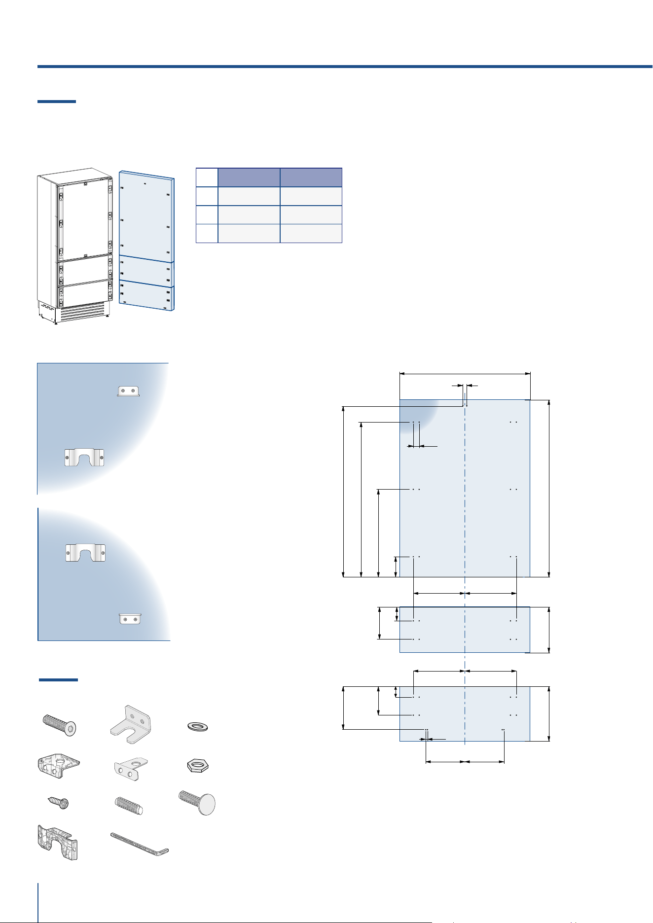
B04000100 Built-in kit
x26
x1
x3x3
x10
x10
x1
x2
x10
x1
x1
EN
4.2 Decorative panels layout for Fridge
with one Bottom-Drawer (1T/0T)
SERIES 899 SERIES 749 SERIES 599
A 897 (35 1/4”) 747 (29 3/8”) 597 (23 1/2”)
B 417 (16 3/8”) 342 (13 1/2”) 276,5 (10 7/8”)
C 354,5 (14”) 279,5 (11”) 203,5 (8”)
A
BB
A
BB
C C
13 (½”)
34 (1
3⁄8”)
6,5 (
¼”)6,5 (¼”)
34 (1
3⁄8”)
1273 (50 1⁄8”)
1163 (45 ¾”)
660 (26”)
157 (6
¼”)
min 1320 (52”)max 635 (25”)
507.5 (20”)
382 (15
1⁄8”)
100 (4”)
www.fhiaba.com · [email protected] · Info Line +39 0434 420160 www.fhiaba.com · [email protected] · Info Line +39 0434 420160
58
4.3 Decorative panels layout
for Fridge with two Bottom-Drawers (0H)
Holes positions:
SERIES 899 SERIES 749
A 897 (35 1/4”) 747 (29 3/8”)
B 417 (16 3/8”) 342 (13 1/2”)
C 354,5 (14”) 279,5 (11”)
4. PANELS MOUNTING
B B
A
C C
B B
13 (½”)
34 (1
3⁄8”)
min 1195 (47”)
1160 (45
5⁄8”)
1044 (41 1⁄8”)
600 (23
5⁄8”)
268 (10
½”)
292,5 (11 ½”)
183 (7 ¼”)
73 (2
7⁄8”)
66 (2
5⁄8”) 157 (6 ¼”)
337 (13 ¼”)
max 415 (16 3⁄8”)
6,5 (¼”)6,5 (¼”)
B04000200 Built-in kit
x34
x1
x3x3
x14
x14
x1
x2
x14
x1
x1
www.fhiaba.com · [email protected] · Info Line +39 0434 420160 www.fhiaba.com · [email protected] · Info Line +39 0434 420160
59
EN
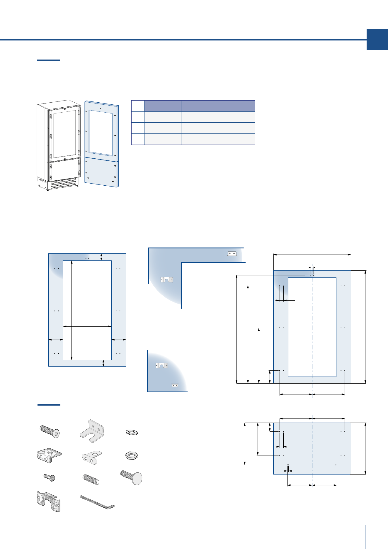
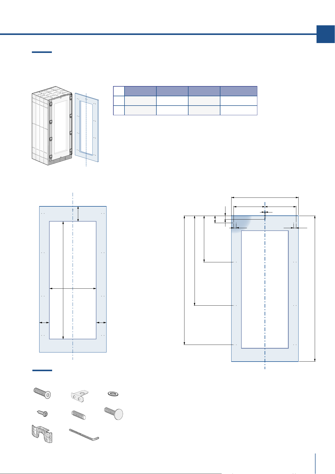
4.4 Decorative panels layout
for Fridge with glass door and one Bottom-Drawer (1T/0T)
Holes positions:Door window dimensions:
SERIES 899 SERIES 749 SERIES 599
A 897 (35 1/4”) 747 (29 3/8”) 597 (23 1/2”)
B 417 (16 3/8”) 342 (13 1/2”) 276,5 (10 7/8”)
C 354,5 (14”) 279,5 (11”) 203,5 (8”)
899: 627 (24 5⁄8”)
749: 477 (18
¾”)
599: 327 (12
7⁄8”)
1075 (42 3⁄8”)
min 130 (5 1⁄8”
)
115 (4 ½”)
135 (5
3⁄8”)
135 (5
3⁄8”
)
B B
B B
A
C C
1286 (50 5⁄8”)
6,5 (¼”)
6,5 (
¼”
)
1152,5 (45 3⁄8”)
650,5 (13
5⁄8”)
148,5 (5
7⁄8”)
13 (½”)
34 (1
3⁄8”)
34 (1
3⁄8”)
min 1320 (52”)
max 635 (25”)
507,5 (20”)
382 (15
1⁄8”)
100 (4”)
B04000200 Built-in kit
x34
x1
x3x3
x14
x14
x1
x2
x14
x1
x1
www.fhiaba.com · [email protected] · Info Line +39 0434 420160 www.fhiaba.com · [email protected] · Info Line +39 0434 420160
60
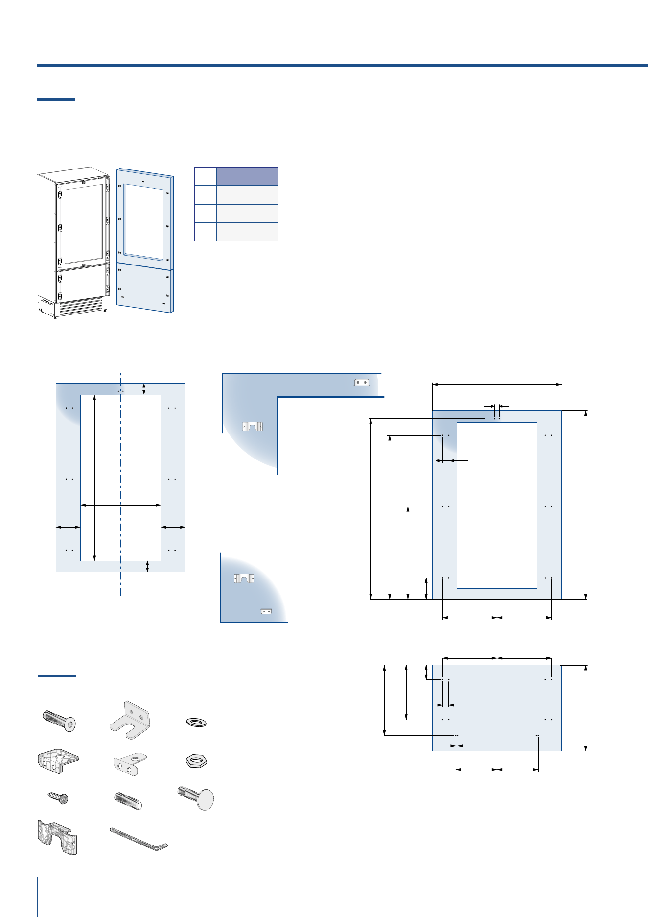
4.5 Decorative panels layout
for Fridge with glass door Brilliance
Door window dimensions: Holes positions:
SERIES 599
A 597 (23 1/2”)
B 276,5 (10 7/8”)
C 203,5 (8”)
4. PANELS MOUNTING
BB
B B
A
C C
1273 (50 1⁄8”)
6,5 (¼”)
6,5 (
¼”)
1152,5 (45 3⁄8”)
650,5 (13
5⁄8”)
148,5 (5
7⁄8”)
13 (½”)
34 (1
3⁄8”)
34 (1
3⁄8”)
min 1320 (52”)
max 635 (25”)
507,5 (20”)
382 (15
1⁄8”)
100 (4”)
599: 327 (12 7⁄8”)
1075 (42 3⁄8”)
min 130 (5 1⁄8”
)
115 (4 ½”)
135 (5
3⁄8”)
135 (5
3⁄8”
)
B04000100 Built-in kit
x26
x1
x3x3
x10
x10
x1
x2
x10
x1
x1
www.fhiaba.com · [email protected] · Info Line +39 0434 420160 www.fhiaba.com · [email protected] · Info Line +39 0434 420160
61
B04000200 Built-in kit
x34
x1
x3x3
x14
x14
x1
x2
x14
x1
x1
EN
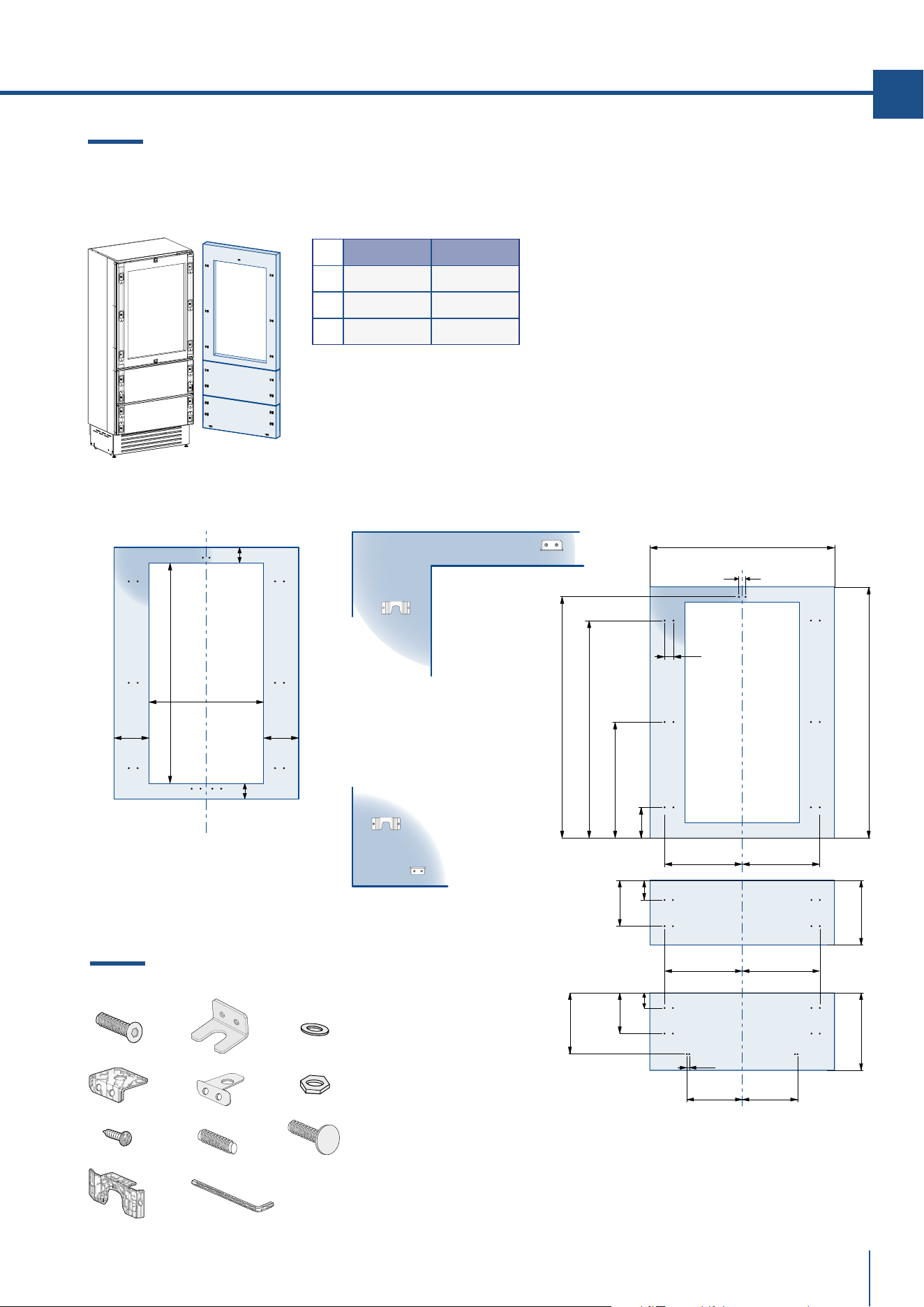
4.6 Decorative panels layout
for Fridge with glass door and two Bottom-Drawers (0H)
Holes positions:Door window dimensions:
SERIES 899 SERIES 749
A 897 (35 1/4”) 747 (29 3/8”)
B 417 (16 3/8”) 342 (13 1/2”)
C 354,5 (14”) 279,5 (11”)
950 (37 3⁄8”)
899: 627 (24 ¾”)
749: 477 (18
¾”)
115 (4
½”)
135 (5
3⁄8”)
135 (5
3⁄8”)
min 130 (5 1⁄8”)
C C
B B
6,5 (¼”)
6,5 (
¼”)
B B
A
1161 (45 ¾”)
1026,7 (40 3⁄8”)
588 (23
1⁄8”)
149,5 (5
7⁄8”)
13 (½”)
34 (1
3⁄8”)
min 1195 (47”)
268 (10
½”)
292,5 (11
½”)
183 (7
¼”)
73 (2
7⁄8”)
66 (2
5⁄8”)
337 (13
¼”)
max 415 (16
3⁄8”)
www.fhiaba.com · [email protected] · Info Line +39 0434 420160 www.fhiaba.com · [email protected] · Info Line +39 0434 420160
62
4.7 Decorative panels layout
for Fridge Column (0F)
SERIES 899 SERIES 749 SERIES 599 SERIES 449
A 897 (35 1/4”) 747 (29 3/8”) 597 (23 1/2”) 447 (17 5/8”)
B 418 (16 1/2”) 343 (13 1/2”) 276,5 (10 7/8”) 200 (7 7/8”)
Holes positions:
4. PANELS MOUNTING
1
13 (½”)
min 1863 (73 3⁄8”)
95 (3
¾”)
1201,5 (47
3⁄8”)
620,5 (24
½”)
1727 (68”)
47 (1 7⁄8”)
B B
A
34 (1 3⁄8”) 34 (1 3⁄8”)
B04009000 Built-in kit
x18
x1x1
x8
x8
x1
x8
x1
www.fhiaba.com · [email protected] · Info Line +39 0434 420160 www.fhiaba.com · [email protected] · Info Line +39 0434 420160
63
EN
4.8 Decorative panels layout
for Fridge column with glass door (0F)
1
Door window dimensions: Holes positions:
SERIES 899 SERIES 749 SERIES 599 SERIES 449
A 897 (35 1/4”) 747 (29 3/8”) 597 (23 1/2”) 447 (17 19/32”)
B 418 (16 1/2”) 343 (13 1/2”) 276,5 (10 7/8”) 200 (7 7/8”)
13 (½”)
min 1863 (73 3⁄8”)
95 (3
¾”)
1201,5 (47
3⁄8”)
620,5 (24
½”)
1727 (68”)
47 (1 7⁄8”)
B B
A
34 (1 3⁄8”) 34 (1 3⁄8”)
1572 (62”)
899: 627 (24 ¾”)
749: 477 (18
¾”)
599: 327 (12
7⁄8”)
449: 177 (6
7⁄8”)
135 (5
3⁄8”
)
135 (5 3⁄8”)
min 130
(5
1⁄8”)
B04009000 Built-in kit
x18
x1x1
x8
x8
x1
x8
x1
www.fhiaba.com · [email protected] · Info Line +39 0434 420160 www.fhiaba.com · [email protected] · Info Line +39 0434 420160
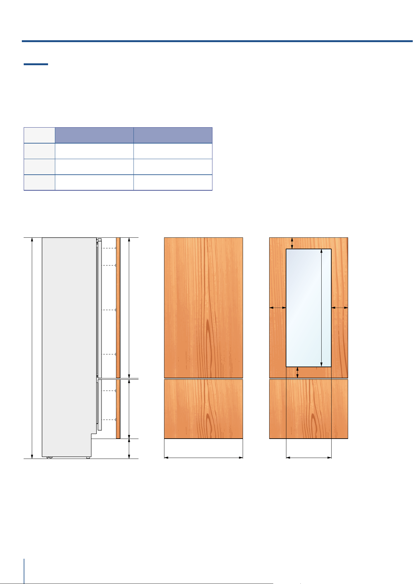
64
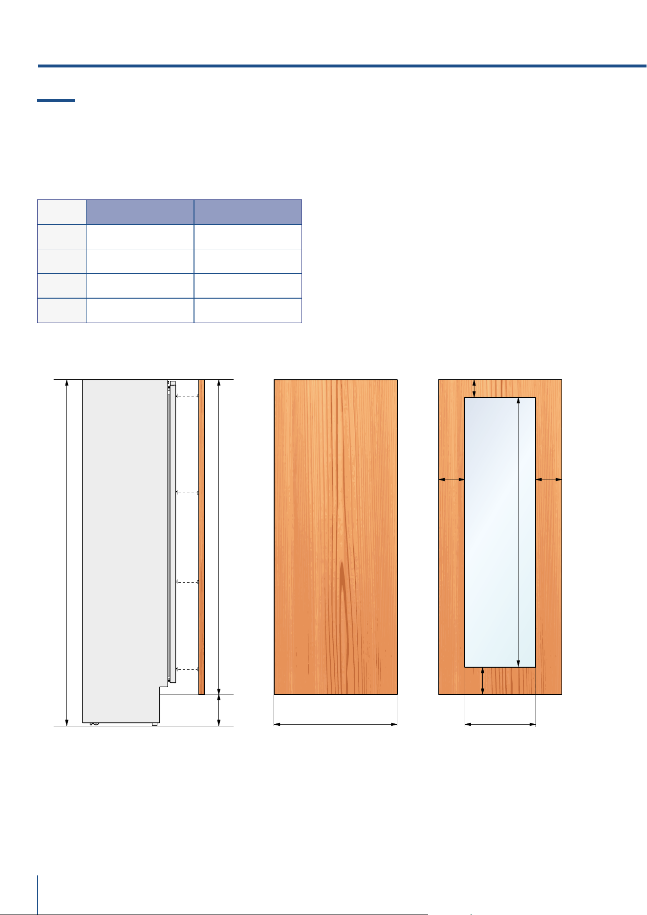
4.9 Panels Dimensions One Bottom - Drawer (1T/0T models)
Panels with width ranging between 18 mm (3/4 in) and 28 mm (1 1/8 in).
Door panels with weight max of 23 kg (51 lb) and drawer panels with weight max of 11kg (25 lb).
Provide installation of decorative panels during installation of the unit.
SERIES DOOR/DRAWER WIDTH A DOOR CUTOUT WIDTH B
899 897 (35 1/4”) 627 (24 3/4”)
749 747 (29 3/8”) 477 (18 3/4”)
599 597 (23 1/2”) 327 (12 7/8”)
min 100 (4”)
4. PANELS MOUNTING
B
115 (4 ½”)
min 130 (5 1⁄8”)
135
(5 3⁄8”)
135
(5 3⁄8”)
1075 (42 3⁄8”)
2050 (80 ¾”)
min 540 (21 ¼”)
max 635 (25”)
187 (7
3⁄8”)
A
3 (1⁄8”)
1320 (52”)
www.fhiaba.com · [email protected] · Info Line +39 0434 420160 www.fhiaba.com · [email protected] · Info Line +39 0434 420160
65
EN
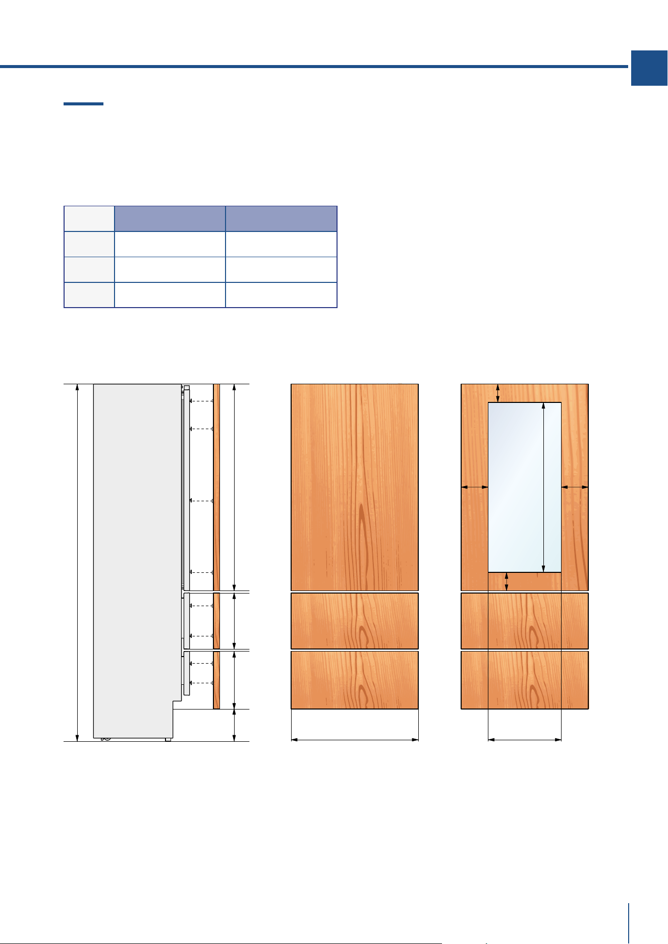
4.10 Panels DimensionsTwo Bottom - Drawers (0H models)
Panels with width ranging between 18 mm (3/4 in) and 28 mm (1 1/8 in).
Door panels with weight max of 23 kg (51 lb) and drawer panels with weight max of 11kg (25 lb).
Provide installation of decorative panels during installation of the unit.
SERIES DOOR/DRAWER WIDTH A DOOR CUTOUT WIDTH B
899 897 (35 1/4”) 627 (24 3/4”)
749 747 (29 3/8”) 477 (18 3/4”)
599 597 (23 1/2”) 327 (12 7/8”)
min
100 (4”)
min 325 (12 ¾”)
max 415 (163⁄8”)
337 (13 ¼”)
3 (1⁄8”)
3 (1⁄8”)
1195 (47”)
2050 (80 ¾”)
187 (7
3⁄8”)
A B
115 (4 ½”)
135
(5 3⁄8”)
135
(5 3⁄8”)
min 130 (5 1⁄8”)
950 (37 3⁄8”)
www.fhiaba.com · [email protected] · Info Line +39 0434 420160 www.fhiaba.com · [email protected] · Info Line +39 0434 420160
66
4.11 Panels Dimensions Column Models (0F models)
Panels with width ranging between 18 mm (3/4 in) and 28 mm (1 1/8 in).
Door panels with weight max of 34 kg (75 lb).
Provide installation of decorative panels during installation of the unit.
SERIES DOOR/DRAWER WIDTH A DOOR CUTOUT WIDTH B
899 897 (35 1/4”) 627 (24 3/4”)
749 747 (29 3/8”) 477 (18 3/4”)
599 597 (23 1/2”) 327 (12 7/8”)
449 447 (17 5/8”) 177 (6 7/8”)
4. PANELS MOUNTING
min 1863 (73 3⁄8”)
max 1960 (77 1⁄8”)
2050 (80 ¾”)
187 (7 3⁄8”)
min 100 (4”)
A B
min 161(6 3⁄8”)
max 258 (10 1⁄8”)
135
(5 3⁄8”)
135
(5 3⁄8”)
min 130 (5 1⁄8”)
1572 (62”)
www.fhiaba.com · [email protected] · Info Line +39 0434 420160 www.fhiaba.com · [email protected] · Info Line +39 0434 420160
67
ø18 mm
HANDLE PRODUCT CODE
HCV HC8 HC7 HC5
Lenght A
794 mm
(43 1/2”)
794 mm
(31 1/4”)
644 mm
(25 3/8”)
494 mm
(19 5/8”)
Distance
between
fixing points X
480 mm
(18 7/8”)
480 mm
(18 7/8”)
490 mm
(19 1/4”)
340 mm
(13 3/8”)
Series
899
749
599
449
899 749 599
EN
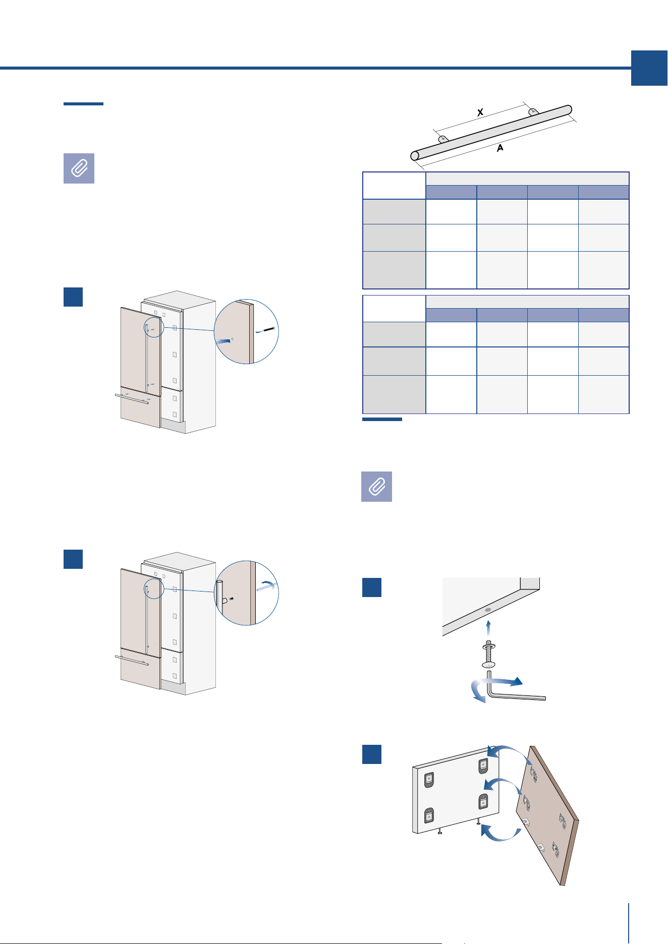
4.12 Mounting the handles
Handles will have to be mounted on the
panels before they are applied to the
fridge.
Operate as follows:
> Drill two holes on the back of the panels accor-
ding to the table below [ 1 ].
> Place the handle on top of the holes and in-
sert the screws through the panel and into the
handle support [ 2 ].
ø30 mm
HANDLE PRODUCT CODE
HV HO8 H07 H05
Lenght A
1104 mm
(43 1/2”)
794 mm
(31 1/4”)
644 mm
(25 3/8”)
494 mm
(19 5/8”)
Distance
between
fixing points X
900 mm
(35 1/2”)
480 mm
(18 7/8”)
490 mm
(19 1/4”)
340 mm
(13 3/8”)
Series
899
749
599
449
899 749 599
4.13 Mounting panels to the door and
the drawer
Once all brackets and small brackets
have been applied to the panels, you can
begin installing the bottom drawer.
Operate as follows:
> Partially tighten the screw to the fixing [ 1 ].
> Hook the bottom drawer panel starting from the
fixings on the bottom [ 2 ].
1
2
2
1
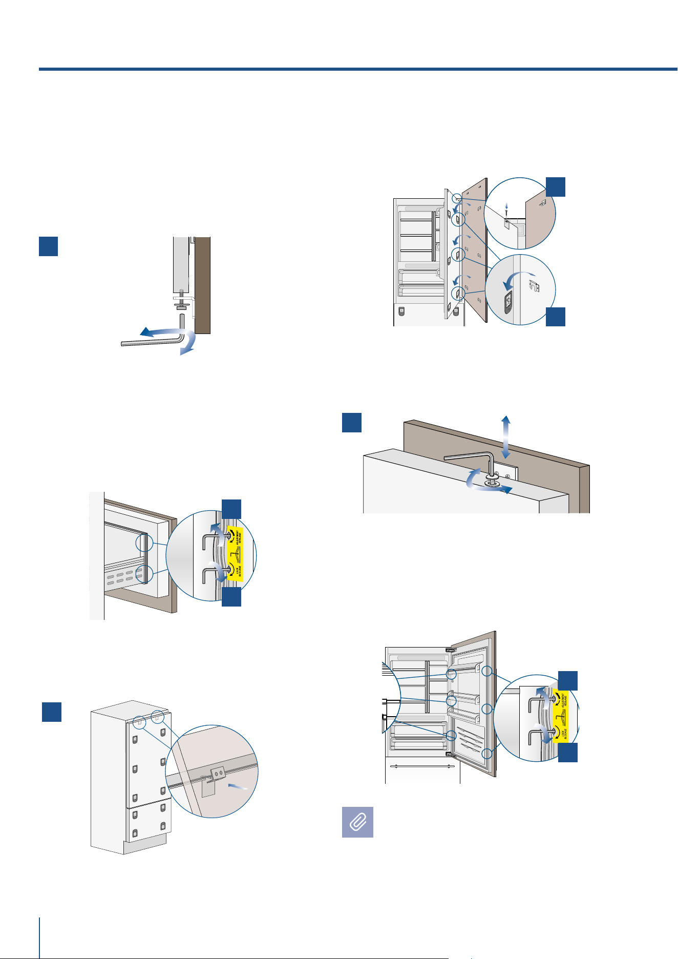
www.fhiaba.com · [email protected] · Info Line +39 0434 420160 www.fhiaba.com · [email protected] · Info Line +39 0434 420160
68
> It is now possible to align panels to adjacent
cabinets in height using the lower alignment bra-
ckets, [ 3 ] tightening or untightening the screws
into position as needed. With the screw slighty
tightened, move the panel sideways to align it
to the other panels on the unit or other adjacent
structures.
> Depth alignment: working from the inside of the
drawer, after lifting up the magnetic seal, adjust
the panel position so it is closer to or further
away from the door using the holes [ 4 ] and then
secure the panel using the holes [ 5 ].
> Hook the panel to the fixing devices starting
from the top aligning brackets [ 6 ].
> At this point, alignment between the panel and
adjacent cabinets can be adjusted using the ali-
gnment brackets and small brackets [ 7] and [ 8 ].
> Vertical alignment: tighten or loosen the screw
in the brackets to raise or lower the panel [ 9 ].
> Depth alignment: working from the inside of the
door, after lifting up the magnetic seal, adjust the
panel position so it is closer to or further away
from the door using the holes [ 10 ] and then fix
the panel in position using the holes [ 11 ].
Once the front panel has been adjusted,
check that the gasket has been repositioned
correctly to assure the door/drawer are
closing correctly and avoid operational
errors of the unit.
4. PANELS MOUNTING
7
8
9
6
4
5
3
10
11
www.fhiaba.com · [email protected] · Info Line +39 0434 420160 www.fhiaba.com · [email protected] · Info Line +39 0434 420160
69
EN
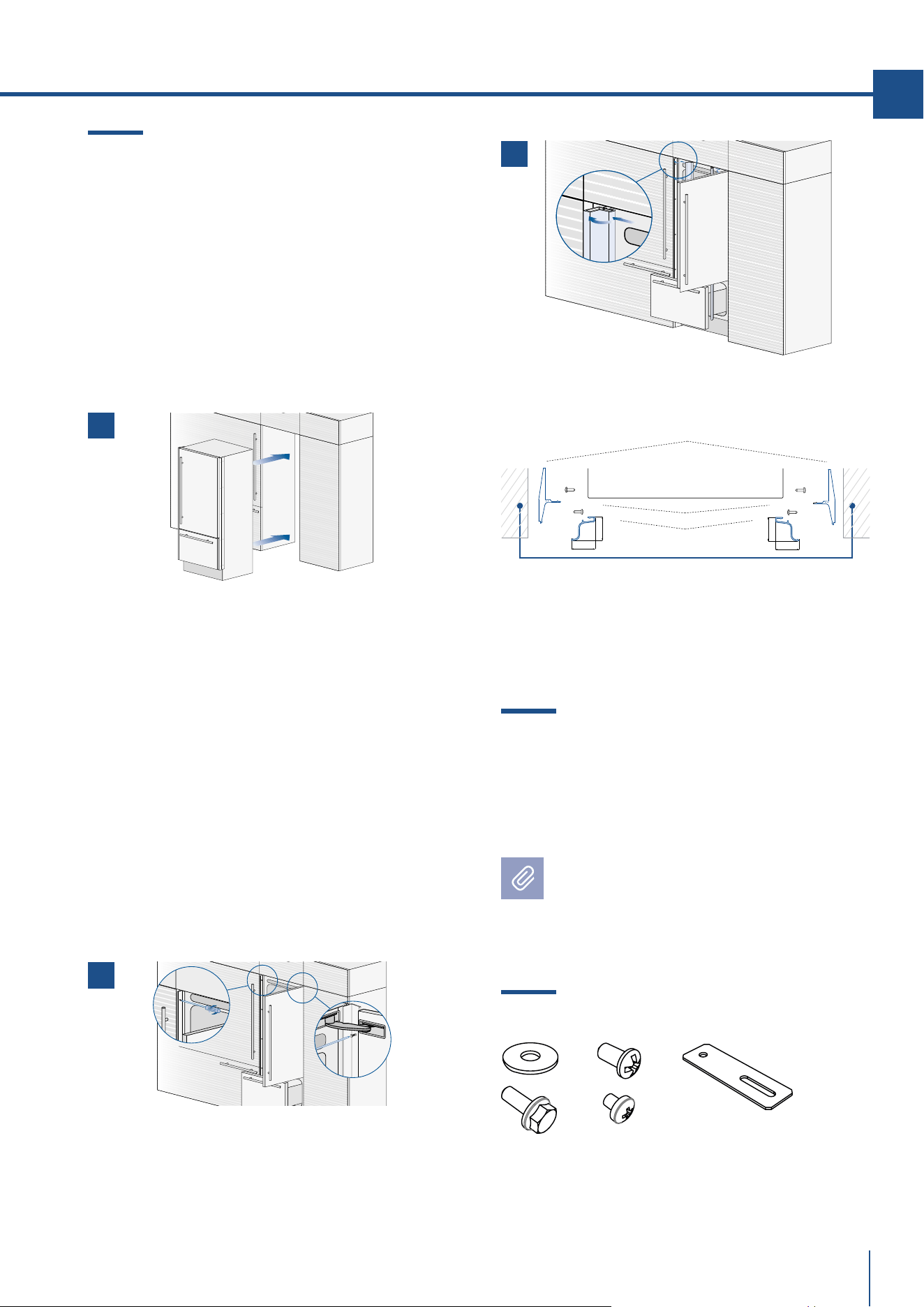
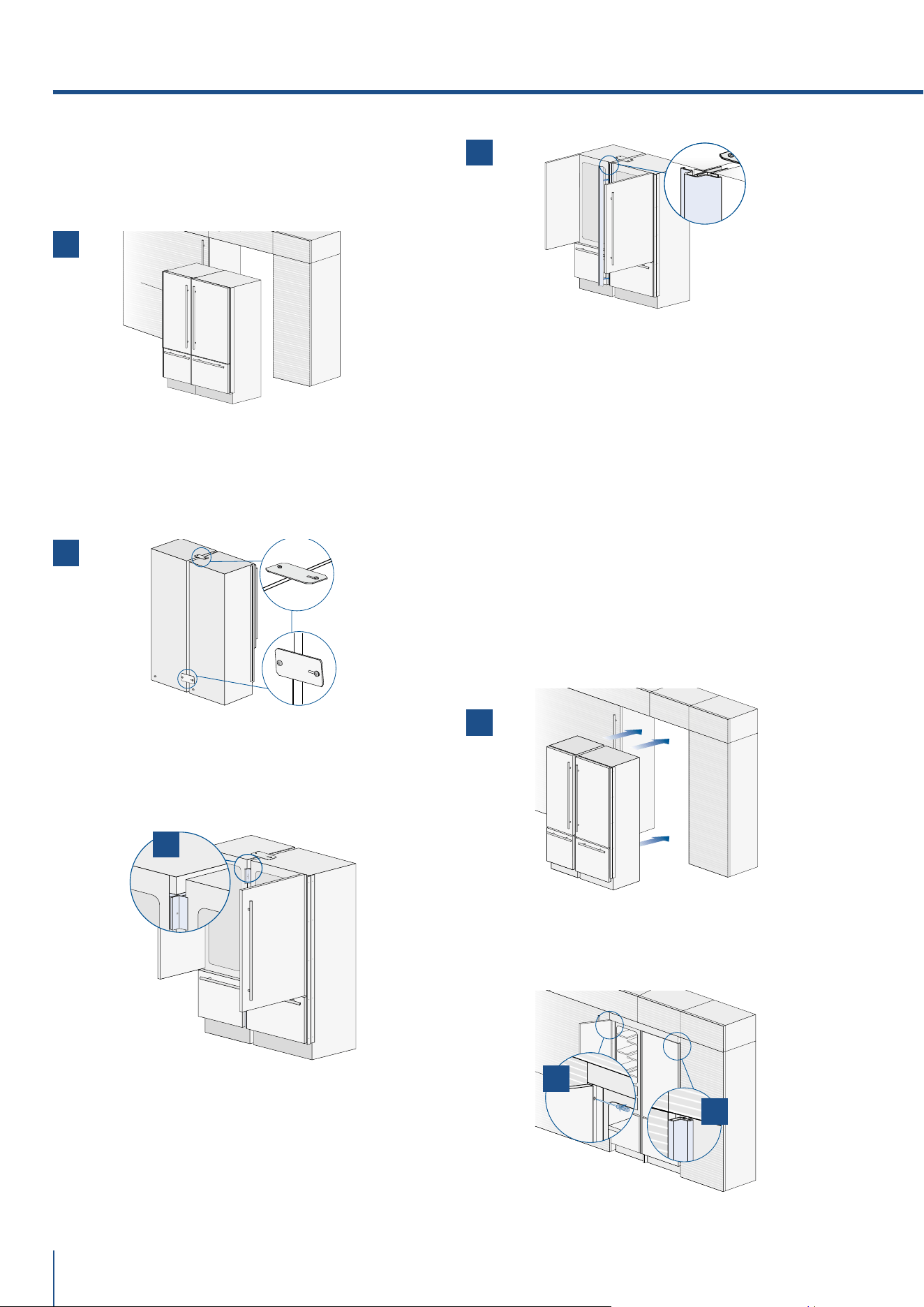
5.1 Built-in installation
single appliance
For a built-in installation, to close gaps between
the appliance and the adjacent cabinets, special
side profiles and PVC covering frames are provi-
ded.
Operate as follows:
> Push the appliance into the installation niche [ 1 ].
> If the unit is to be installed inside a niche or
within an enclosed structure, it is necessary to
design a ventilation shaft at the back of the ni-
che to assure proper ventilation at the back of the
unit. A 5 mm gap is sufficient to prevent overhe-
ating. Always mount front panels on door and
drawer before pushing the unit into its final posi-
tion inside the niche or structure.
> Secure the appliance to the adjacent cabinets
by fixing to these the side profiles previously
mounted on the appliance [ 2 ].
To make this operation easier keep the door and
the drawer open.
> Check the levelling of the appliance, adjusting
its feet and wheels to correct it.
> Mount the profiles the covering frames: first in-
sert them laterally and then push firmly until a
“click” is heard [ 3 ].
5. INSTALLATION
Side profiles mounting:
A PVC connecting element,
alternatively: C plastic connecting brackets
B Alluminium frame
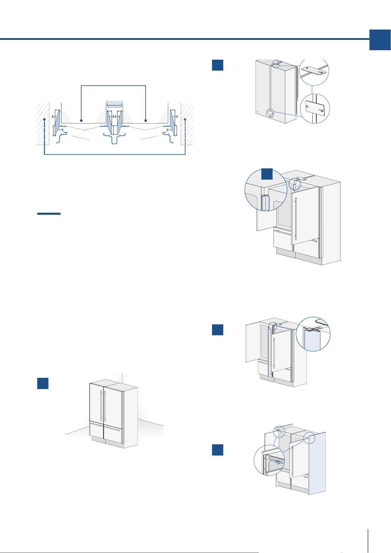
5.2 Built-in installation two or more
appliances
Required accessories to be ordered separately:
> Central connection Kit (KCC)
Special side profiles and PVC covering fra-
mes are provided for closing gaps between
the appliance and the adjacent cabinets.
Appliance
Wall or furniture
B
C
A
22 (7⁄8”)
22 (7⁄8”)
22 (7⁄8”) 22 (7⁄8”)
x2
x2 x2
x5
x2
B04017900 Union kit
3
1
2
www.fhiaba.com · [email protected] · Info Line +39 0434 420160 www.fhiaba.com · [email protected] · Info Line +39 0434 420160
70
Operate as follows:
> Position the appliances in front of the installation
area, leaving enugh space to operate at their back
[ 1 ].
> Move at the back of the appliances to mount the
joining brackets: fix on side of the top and lower
brackets to one of the appliances and subsequently
to the other [ 2 ].
> Place the two units side by side and join them at
the front attaching the profiles with the supplied
screws [ 3 ] .
> Finish o by mounting the central cover frame
onto the central profiles, by pushing it until a click
is heard [ 4 ].
> Once completed the previous steps, push the
units in their final position [ 5 ].
If the units are to be installed inside a niche or
within an enclosed structure, it is necessary to de-
sign a ventilation shaft at the back of the niche to
assure proper ventilation at the back of the unit of
about 20mm. Always mount front panels on door
and drawer before pushing the unit into its final po-
sition inside the niche or structure.
> Check the levelling of the appliance, adjusting its
feet and wheels to correct it.
> Secure the appliance to the adjacent cabinets
by fixing to these the side profiles [ 6 ]. To make
this operation easier keep the door and the drawer
open.
> Mount the covering frames onto the profiles, first
insert them laterally and then push firmly until a
“click” is heard [ 7 ].
5. INSTALLATION
4
6
7
5
2
3
1
www.fhiaba.com · [email protected] · Info Line +39 0434 420160 www.fhiaba.com · [email protected] · Info Line +39 0434 420160
71
EN
Side and central profiles mounting:
A - Side connection profile in PVC.
B - Aluminum cover frame
C - Central covering frame in aluminum
5.3 Free-standing installation
two or more appliances
Required accessories to be ordered separately:
> Central Connection Kit (KCC)
> Freestanding Kit
Aluminium profiles can be used to close the spaces
between the appliance and adjacent structures.
Operate as follows:
> Position the appliances in front of the installation
area, leaving enough space to operate at their back.
> Peel o the self adhesive protection and apply the
insulated anticondensation panel to the side of one
appliance [ 1 ].
> Move at the back of the appliances to mount the
joining brackets: fix one side of the top and lower
brackets to one of the appliances and subsequently
to the other [ 2 ].
> Place the two units side by side and join them at
the front attaching the two profi les with the supplied
screws [ 3 ].
> Finish o by mounting the central cover frame
onto the central profiles, by pushing it until a click
is heard [ 4 ].
> Attach the side panels to the unit, mounting them
on the side profiles [ 6 ]
Appliance
Wall or furniture
B
B
AA
C
6,5 (¼”)
6,5 (¼”)6,5 (¼”)
6,5 (¼”)
20 (¾”)
20 (¾”)
18 (¾”)
13 (½”)
5
4
2
1
3
www.fhiaba.com · [email protected] · Info Line +39 0434 420160 www.fhiaba.com · [email protected] · Info Line +39 0434 420160
72
> Attach the aluminum cover [ 6 ] to each side pro-
file, pressing onto them until they ‘click’ together.
> Mount the top panel [ 7 ] on top of the unit, using
the screws provided with the kit.
> Adjust the height of the unit with the leveling feet
and the back wheels.
Side panels and central profile mounting
A - Side connection profile in PVC.
B - Aluminum cover frame
C - Central covering frame in aluminum
5.4 Maximum cabinet depth over
“Integrated” refrigerator with
single door panel
It is possible that the design of the kitchen and,
in particular, of the niche where the “Integrated”
refrigerator is going to be fitted includes a cabinet
right above the refrigerator itself that must be
closed with the same panel mounted on the
Integrated refrigerator door.”
In this case, the total depth of the cabinet without
the door (above the refrigerator) must not exceed
the total depth of the refrigerator itself [ 1 ].
This will allow the panel attached to the refrigerator
door to open correctly without interference during
its rotation up to 105°.
1
5. INSTALLATION
Appliance
585 (23”)
650 (25 ⅝”)
47 (1 ⅞”) + front panel thickness
B
B
AA
C
6,5 (¼”)
6,5 (¼”)6,5 (¼”)
6,5 (¼”)
20 (¾”)
20 (¾”)
18 (¾”)
13 (½”)
6
7
www.fhiaba.com · [email protected] · Info Line +39 0434 420160 www.fhiaba.com · [email protected] · Info Line +39 0434 420160
73
6. COMPLETING THE INSTALLATION
EN
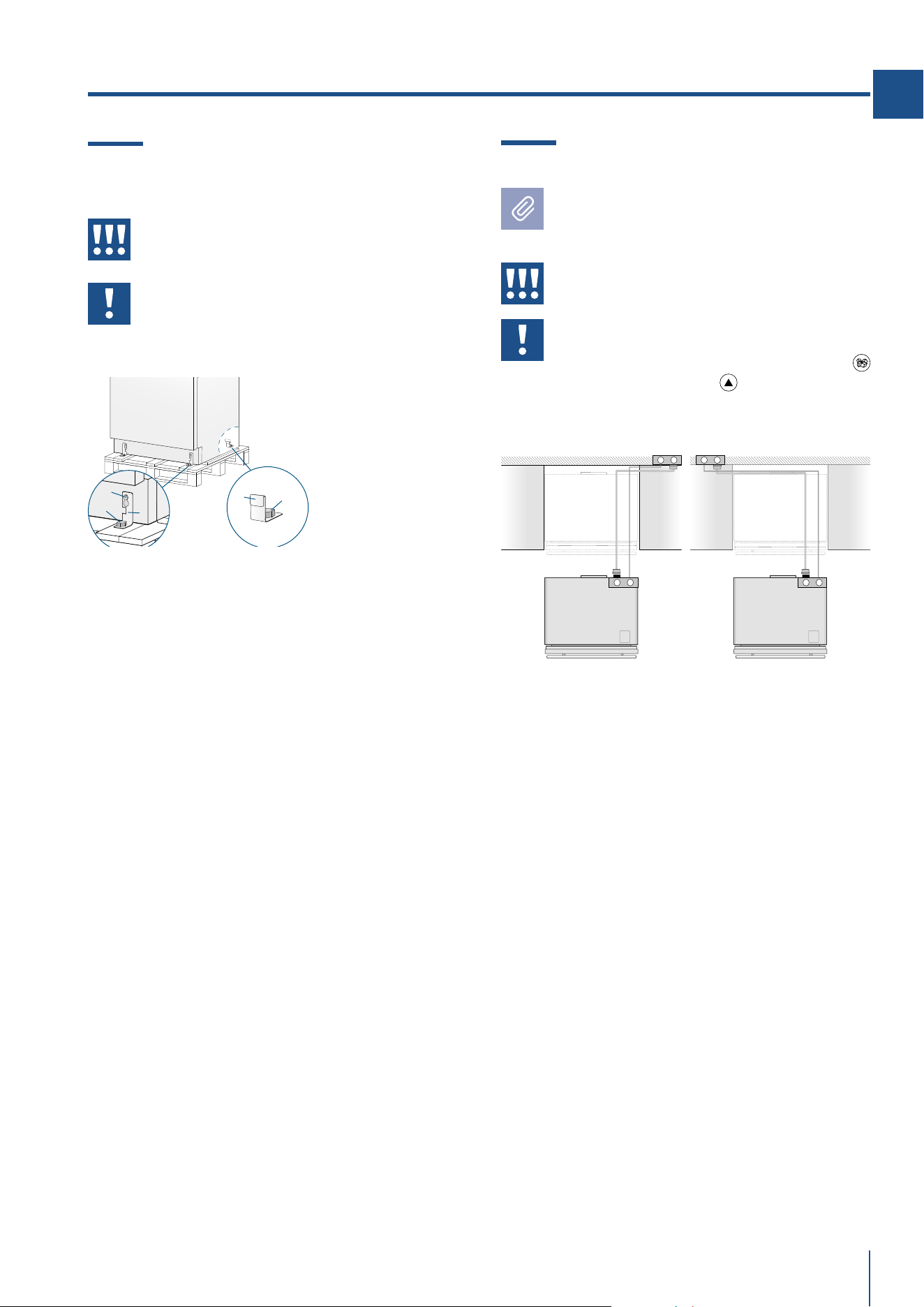
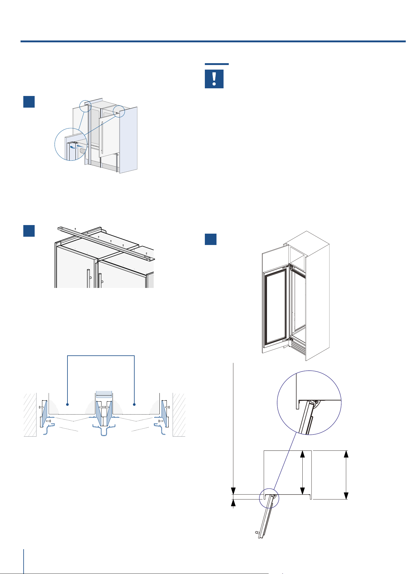
6.1 Anti-tipping safety assembly
To prevent the appliance from tipping over
an extra-long kit is vailable up on request
if the appliance needs to remain distanced
from the wall, it is mandatory to install two
brackets on the upper part of the appliance
for fixing it securely to the wall.
Operate as follows:
> The brackets should be applied as illustrated us-
ing the provided screws and expansion plugs.
Place a bracket on the top of the appliance in corre-
spondence to the fixing holes and against the wall
[ 1 ].
> Mark up the holes position on the wall [ 2 ].
> Drill the wall with an 8 mm (3/8”) bit and insert
the expansion plug [ 3 ].
> Reposition the bracket and fix it first to the cabi-
net and then to the wall [ 4 ].
To avoid danger of the appliance tipping over
it is mandatory to secure the appliance to
the wall by means of two special brackets.
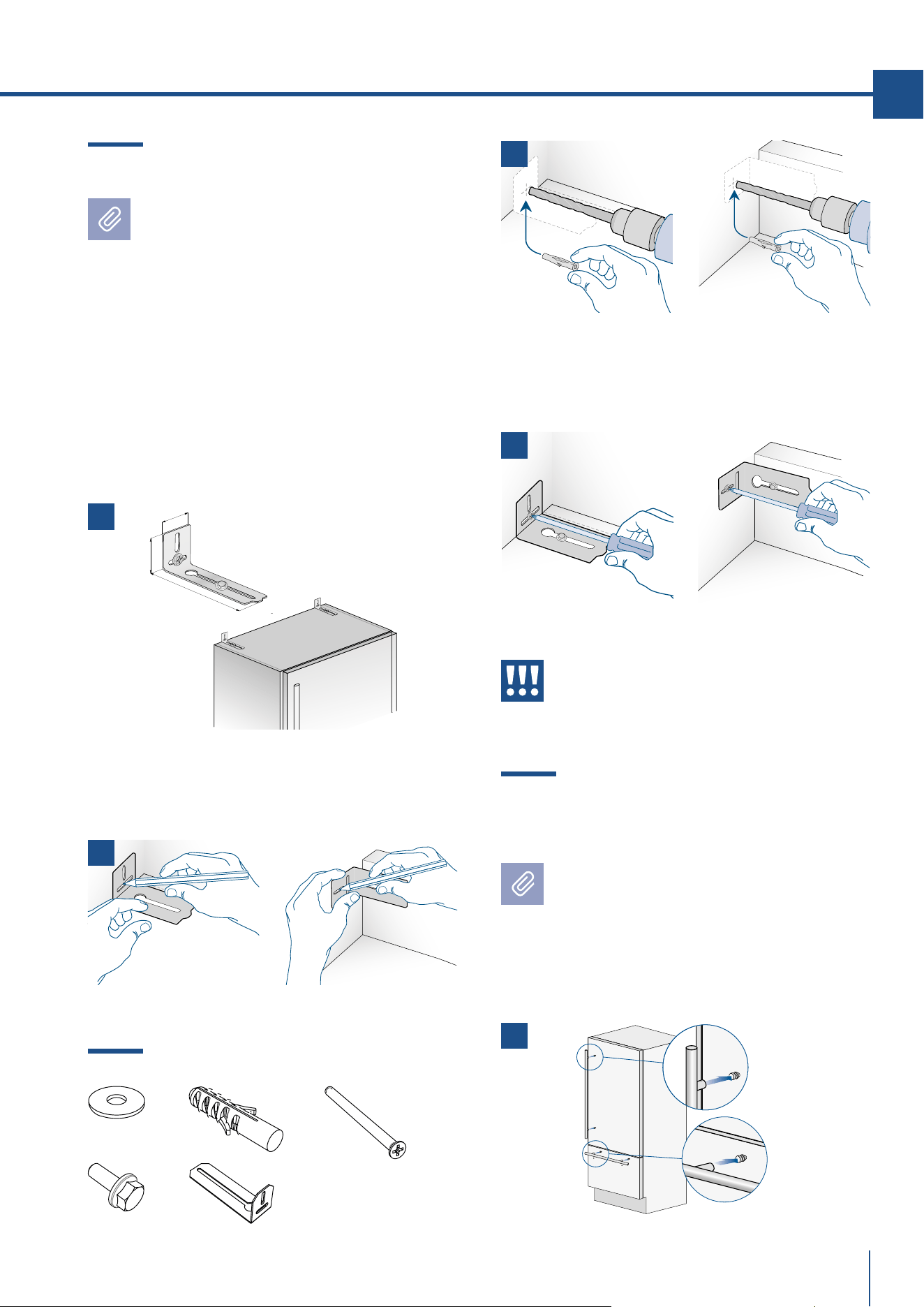
6.2 Mounting the handles
on stainless front
To mount the handles onto the door and
the drawer operate as follows:
Operate as follows:
> Insert the two handle spacers onto the supports
already available on the door and the drawer [ 1 ].
2 x
6 x
152 (6”)
59 (
2
3⁄8
”)
45 (1
5⁄8
”)
B04000200 Anti-tip kit
x2
x2
x2
x4
x2
1
2
3
4
1
www.fhiaba.com · [email protected] · Info Line +39 0434 420160 www.fhiaba.com · [email protected] · Info Line +39 0434 420160
74
> Screw in the Allen screws available on the handle [ 2 ].
The screws must be tightened in by means of a
2.5 mm (1/8”) hex wrench.
6.3 Ventilation and Plinth
INTEGRATED AND CLASSIC SERIES
In the event that the design of the environment
provides for the installation of a front plinth to
unify the overall view, it is necessary to use a
perforated plinth to ensure proper ventilation of
the equipment.
The drawings below indicate, for each width
available in the Integrated series, the size of
the area and the percentage of surface to be
drilled; the type of drilling (vertical or horizontal
grid, for example) remains at the discretion of the
designer.
6. COMPLETING THE INSTALLATION
Ventilation is ensured by a forced air system
through a grid positioned in the lower part of the
equipment. If a front plinth is provided, it must
provide an opening to ensure proper ventilation of
the equipment as per drawing.
The type of drilling of the front plinth (eg vertical
or horizontal slots) is at the discretion, however, it
must guarantee an open surface equal to 50% of
the total.
In this case, to further improve ventilation, it is
suggested to remove the original grille.
The ventilation grille is magnetically fixed to the
equipment and can be easily removed, even by the
user, to check and clean the condenser from any
accumulation of dust.
The ventilation grille must not be blocked or covered
in any way. It also needs to be dusted / cleaned
regularly.
A
B
C
C
100 (4”)
SERIE 899 SERIE 749 SERIE 599 SERIE 449
A 860 (33 7/8”) 710 (27 15/16”) 560 (22”) 410 (16 1/8”)
B > 100 (4”)
C 10 (3/8”)
min 50%
2
www.fhiaba.com · [email protected] · Info Line +39 0434 420160 www.fhiaba.com · [email protected] · Info Line +39 0434 420160
75
EN
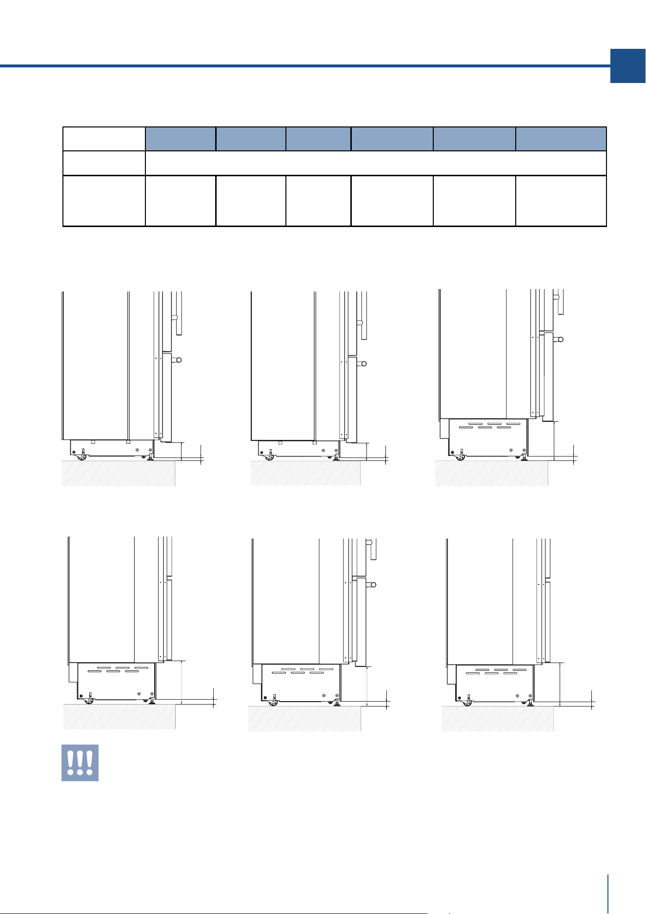
0 -
25 (0-1”)
146
(5 ¾”)
0 -
25 (0-1”)
97
(3 ⅞”)
X-Pro (XS) County (AS) Classic (KS) Integrated (S) Brilliance
Classic (BS)
Brilliance
Integrated (BC)
0 - 25 mm (0 - 1” in)
97 mm
(3 7/8” in)
128 mm
(5 1/8” in)
146 mm
(5 3/4” in)
min 100 mm
(3 7/8” in)
max 187 mm
(7 3/8” in)
146 mm
(5 3/4” in)
min 100 mm
(3 7/8” in)
max 187 mm
(7 3/8” in)
0 -
25 (0-1”)
128
(5 ⅛”)
0 -
25 (0-1”)
min 100
(3 ⅞”)
max 187
(7 ⅜”)
0 -
25 (0-1”)
146
(5 ¾”)
0 -
25 (0-1”)
min 100
(3 ⅞”)
max 187
(7 ⅜”)
Series: X-Pro Series: Country Series: Classic
Series: Integrated
Series: Brilliance Classic Series: Brilliance Integrated
Plinth size
Height of the panel
from the floor
Feet Adjustment
Models
Based on the adjustment of the feet and the height of the panel from the floor, the customer defines the perforated
plinth to be installed on the equipment.
6. COMPLETING THE INSTALLATION
www.fhiaba.com · [email protected] · Info Line +39 0434 420160 www.fhiaba.com · [email protected] · Info Line +39 0434 420160
76
X-PRO SERIES:
Ventilation is insured by a forced air system
through a grille located in the upper part of the
appliance. This grille should never be covered by
panels or any other devices that could reduce its
efficiency. Please refer to page 5-6 to ensure cor-
rect air circulation.
6.4 Post installation control
Check that the front levelling feet have been pro-
perly installed.
Check that the connection to the water system
does not have any leaks and that the closing tap is
easily accessible.
Check that the electrical connection is correctly
installed and that the multipole switch and socket
are easily accessible.
Check the perfect alignment of the appliance
with adjacent structures.
Check that all adhesive tape and external or in-
ternal temporary protective devices have been re-
moved.
Check the perfect closing of the doors and the
smooth sliding of the drawers and shelves.
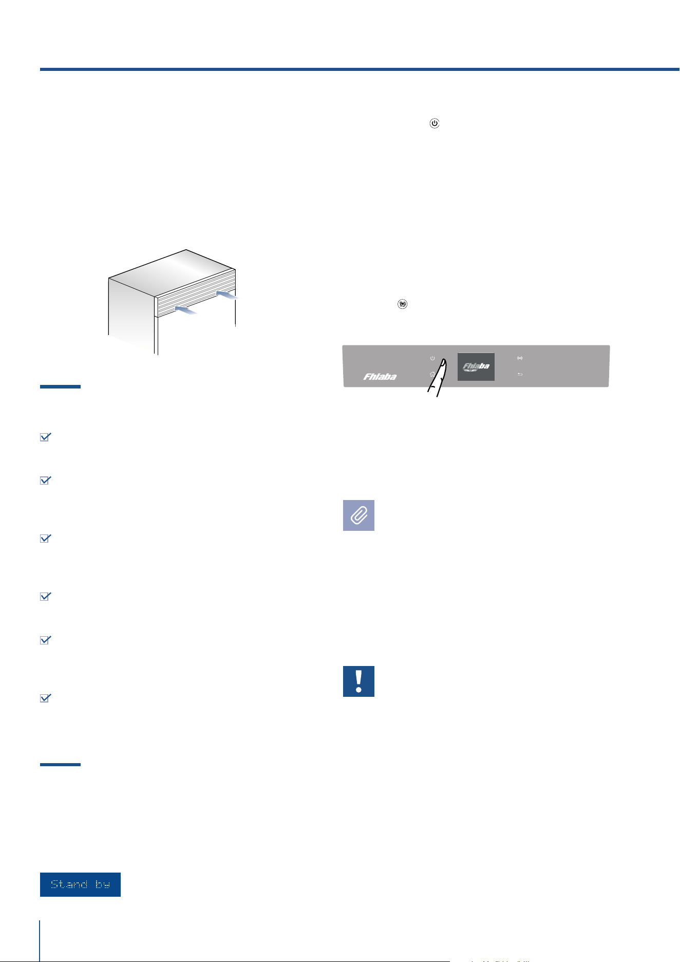
6.5 Start up
> To start the appliance, connect the plug to the
electrical mains: at this point, when opening the
door, the control panel will usually visualize the
message “Stand by”, and all the panel keys be off
>To turn on all the appliance compartments,
press the Unit
button for three seconds. The
display will show the message “Initial test” for
approx. 2 minutes. After this phase the compres-
sors will start up and remain on until the default
temperature set up in the factory is reached. Do
bear in mind that this condition could last seve-
ral hours. If the appliance is provided with an Ice
Maker, prior to switching it on make sure that
the water filter cartridge is installed, then fill the
water system. To this purpose switch off the Ice
Makerand performe a manual clean procedure.
At the end switch the Ice Maker on again by tou-
ching the
button.
> For further information about the appliance
operation, refer to the User Manual.
If at the first start - up the message Stand
by does not appear, but other messages ap-
pear, such as Fridge too warm, Fresco too
warm, Freezer too warm, or sound signals
are activated, it means that the appliance
has already started the cooling process.
If this is the case, deactivate any possible
acoustic signals by pressing the Alarm but-
ton, close the door and wait until the set
temperature is reached.
It is necessary to let the unit reach the correct
temperature before foods are stored inside.
6. COMPLETING THE INSTALLATION
Serigraa B02919202 VETRO USER 599 TFT - FHIABA
Limite per graca parti retro-illuminate - la parte bianca è trasparente
Testo e graca
00
°C+
Impostazioni
Funzioni
00
°C+
00
°C-
Colore SMEG
colore C71
cambiamento dimensioni foro
56x43mm 29-05-2019
lati obliqui 30-03-2020
icone ridotte 29-05-2019
BISELLATURA SUI 4 LATI
BISELLATURA SUI 4 LATI

www.fhiaba.com · [email protected] · Info Line +39 0434 420160 www.fhiaba.com · [email protected] · Info Line +39 0434 420160
77
EN