1-844-446-8729
THIS GUIDE CONTAINS
IMPORTANT SAFETY
INFORMATION.
For product assistance &
missing or replacement parts:
WE CAN HELP
PLEASE READ AND KEEP
FOR FUTURE REFERENCE.
MONDAY-FRIDAY 9am to 5pm MST
Find more at Walmart.com
NOTE: Intended for riders 5'2"-5'10"
Maximum weight limit: 264lbs/120kg
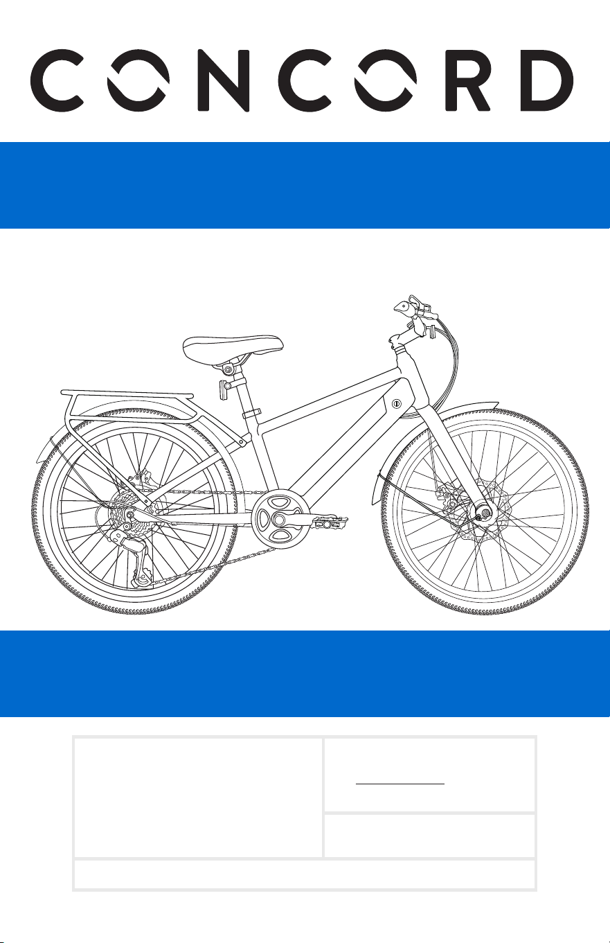
26in Electric Bike
USER GUIDE

2
IMPORTANT:
Carefully read and follow this manual (and any other materials included with this bike) before riding.
Please retain this manual for future use. If this bike was purchased for a child, it is the responsibility
of the purchaser to verify the bike has been properly assembled, and that the user has been properly
trained and instructed in use of the bike.
This manual is provided to assist you and is not intended to be a comprehensive manual covering all
aspects of maintaining and repairing your bicycle. The bicycle you have purchased is a
complex piece of
equipment that must be properly assembled and maintained in order to be ridden safely. If you have any
doubts about the assembly or your ability to properly assemble and maintain the bicycle, you must have
it assembled and maintained by a professional bicycle mechanic.
DANGER! Failure to properly assemble and maintain your bicycle
could result in serious injury or death to the rider.
Contents & Information
CONTENTS & INFORMATION ........ 2
PARTS IDENTIFICATION ............... 3
BEFORE RIDING ......................
Record Serial Number ................. 3
Responsibility of the Owner .......... 4
Properly Fitting Helmet ............... 5
Before Every Ride ....................... 5
Rules of the Road ....................... 6
Warning Message ....................... 8
Correct Frame Size ....................
. 10
Riding Position ........................... 10
Setup Time ................................ 11
Tools Needed ............................. 11
Parts Diagram ............................ 11
ASSEMBLY ...........................
Handlebars .............................. 12
Front Wheel ............................ 13
Seat Assembly ......................... 14
Pedals .................................... 16
In
ate Tires ............................. 17
HOW TO FIX A FLAT ...................... 20
OPERATION .........................
Shifting Gears ........................... 21
Battery
Headlight
....................
....................
.
.
.
.
.
.
.
.
.
.
.
.
.
.
....
....
.
.
... 1
1
8
9
Front Fender ........................... 18
Shifter Adjustment .................... 21
Disc Brakes ............................. 22
Brake Adjustment ..................... 22
E-Bike Console Function ........... 23
Battery Information ................. 24
Display Troubleshooting Guidance
..............................................
25
MAINTENANCE
12-18
21-25
3-11
26-27
28-29
30
........................
Routine Maintenance ................. 26
Wheel Inspection ........................ 26
Tire Inspection ........................... 27
TROUBLESHOOTING ..................
WARRANTY ...................................
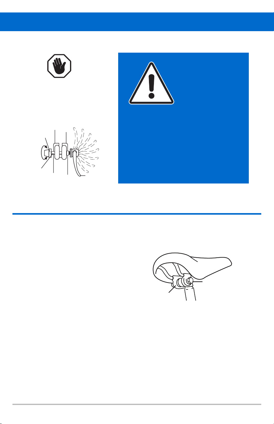
ALWAYS WEAR A PROPERLY FITTED
HELMET WHEN YOU RIDE YOUR BICYCLE.
DO NOT RIDE AT NIGHT.
AVOID RIDING IN WET CONDITIONS.
3
Parts Identi cation
Top Tube
Front Fork
Front fender
Front Disc Brake
Front Hub
Head Tube
Seat
Battery
Tube
Tire
Rear Brake
Rear rack
Rear fender
Rim
Spokes
Motor
Rear Derailleur
Chain
Chain Stay
Seat
Seat Clamp
Seat Post Clamp
Seat Post
Down
Tube
Chainwheel
Crank Arm
Pedal
Rear Reflector
IMPORTANT: Use this Diagram
when reading this manual to help
you understand directions
and instructions.
RECORD SERIAL NUMBER
Each bicycle has a serial number stamped into
the bottom of the frame (See Illustration).
Record this number HERE to keep for future
reference. This number can be helpful to
reclaim your bike if ever lost or stolen.
THIS INFORMATION IS ONLY AVAILABLE
ON THE BIKE ITSELF. There is no record
of your serial number at the store purchased
or with our company. It is your responsibility
to record this information.
Serial Number: ____________________________________________________________________________________
###
Serial Number Location:
Bicycle shown upside down
Serial Number
StemGrips
Shifter
Handlebar
Display
Brake Lever
Throttle
Brake Lever

4
Responsibility of the Owner
IMPORTANT: Reading and following the information and instructions in this manual are essential to your
ability to ride safely.
1. It is the responsibility of the owner, or in the case of a younger rider the parents of the rider, to
be certain all assembly instructions have been followed, even if the bike has been assembled by
the seller or a professional assembly company.
2. Brakes are essential to saf
ety. Be sure they are checked and working properly before each use.
Remember that any mechanical system changes condition during use and must be maintained
and checked before each use.
3. Rules for bicycle use (bicycle laws) vary from location to location so be certain the rider knows
and understands the rules that apply to bicycle usage in your area. Wearing a helmet and using
lights and re ectors are two ex
amples of rules which may exist and which make sense as rider
safety precautions at all times.
4. Know how to operate the bicycle and all equipment on it before rst use and be certain anyone
else allowed to use the bike knows how to properly and safely use the bike as well.
5. There are many di erent types of bicycles and often these types are designed for di erent
uses. Make sure you know what
type unit you have and do not exceed its service limitations. Be
sure you check and understand the bicycle classi ciations set forth below,
including size of the unit that is proper for the rider to insure good control during use. Riders
who are too small may have control problems. Do not overload a unit with a rider that is too
heavy or too large, and do not attempt to carry extra passengers, packag
es or loads on the
bicycle. Do not attempt to use street bikes for road riding.
26" Electric Bikes. Max weight of rider+luggage+bike = 264lbs/120kg.The use of a bike in hazardous
CAUTION: Any adjustments you make are entirely at your own risk. Do NOT use
If you are unsure how to carry out repairs or
conditions such as on changeable and uneven surfaces can put very high, unpredictable stress on the bike
and its components. Lack of rider skill and experience in these condi
tions can further increase this
stress, leading to the possibility of serious damage to the bike and injury to the rider. Wear a helmet at all
times. Check your bike frequently for loose or damaged parts and do required maintenance.
NOTE: Carefully read this manual and follow instructions. Your bicycle may come with additional
instruction sheets that cover features unique to your bike. Please ensure that y
ou read and become
familiar with their contents. Proper assembly, use and maintenance of components like quick release
hubs and brakes are essential to rider safety. Always wear a CPSC approved helmet when riding your
bike. Familiarize yourself with local and state tra
c
and use laws. Keep all materials which come with the
bike for future reference.
Any major service or adjustments on your bike should be carrie
d out by a competent adult or
professional bike mechanic. If you wish to make adjustments yourself, this manual contains important
tips on how to do it.
your bike for freestyle and stunt riding, jumping or competitive events. Even if you are riding a mountain
bike, you should know that o -road use or any similar activities can be dangerous, and you are warned
that you assume the risk for personal injury, damages or losses incurred from such use. Do not ride your
bike when any part is damaged or not working properly.
maintenance on your bike, it is vital that you promptly consult a local bike mechanic for professional
assistance and support.
WARNING: AS WITH ALL MECHANICAL COMPONENTS, THE BICYCLE IS SUBJECTED TO WEAR
A
ND HIGH STRESSES. DIFFERENT MATERIALS AND COMPONENTS MAY REACT TO WEAR
OR STRESS FATIGUE IN DIFFERENT WAYS. IF THE DESIGN LIFE OF A COMPONENT HAS BEEN
EXCEEDED, IT MAY SUDDENLY FAIL, POSSIBLY CAUSING INJURIES TO THE RIDER. ANY FORM OF
CRACKS, SCRATCHES OR CHANGES OF COLORING IN HIGHLY STRESSED AREAS INDICATE THAT
THE LIFE OF THE COMPONENT HAS BEEN REACHED AND SHOULD BE REPLACED.
i
i
i
l
f
f
f
of
f
f
f
f
f
f
f
f
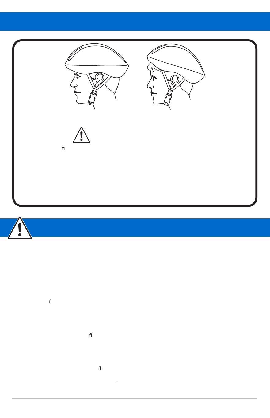
CORRECT
Forehead Covered
INCORRECT
Forehead Exposed
ALWAYS WEAR A HELMET
IT COULD SAVE YOUR LIFE!
A properly tting, CPSC approved, bicycle helmet should be worn at all times when
riding your bicycle.In addition, if you are carrying a passenger, only use an approved
child safety seat; and remember, the passenger must also be wearing a helmet.
The correct helmet should: - be comfortable
- be lightweight
- have good ventilation
- cover the forehead
- be securely fastened on the rider.
5
Properly Fitting Helmet
Before Every Ride
Just a minute spent before each ride can signi cantly improve your safety and the enjoyment of your
ride. So, each time before you ride, make a habit of performing the following safety checks.
• Stand in front of the bicycle facing rearward and hold the front wheel securely between your
legs. Try to twist the handlebars and verify that they do not move. Then pull the handlebars up,
trying to lift the bike. There should be no movement.
• Try to push the front wheel from side to side and con rm that
it feels tight and will not wobble.
Lift the front wheel up by the handlebars and strike wheel downward with the heel of your hand
and con
rm that it is securely attached to the fork. Spin the front wheel and con rm that it does
not wobble or contact the fork or brake pads.
• Try to lift, push down on and twist the seat to con rm that it is tight.
• Look at the connection of the pedals to the crank arm. You should see no pedal screw threads
and the pedal should feel
rm and be parallel to the ground.
• Test your brake(s). Apply your brake(s) and make sure that they feel rm to the touch, and then
spin the wheel(s). Apply the brakes. They should stop the wheel(s).
• Check to be sure that fenders and accessories are rmly attached and will not contact any
moving parts. Make sure all re
ectors are in position and not broken.
Now, put on your BICYCLE SAFETY HELMET and enjoy your ride. Your safety is well worth
just a minute. Also, be sure to read and follow the warnings and instructions in the Assembly,
Maintenance and other sections of this manual.
i
i
i i
i
i
i
i
f
f
f
f
f
f

6
Rules of the Road
In the interest of safe cycling, make sure you read and understand the owner’s manual. In this manual
you will nd DANGER, WARNING , CAUTION, IMPORTANT, and NOTE or NOTICE. These are
important signal words telling you to pay special attention to that text as rider safety is involved.
– DANGER and WARNING: Pay special attention to these, since failure to do so could result in
serious injury or death to the rider or others.
–
CAUTION: If not followed, these instructions could result in injury or mechanical failure or
damage to the bicycle.
– NOTE or NOTICE or IMPORTANT: These specify something that is of special interest.
IMPORTANT: Before you ride this bicycle, read this RULES OF THE ROAD section
and check that all
parts are installed and working as per this manual. If you understand how the bicycle operat
es, you will
get the best performance. When you read this instruction book, compare the illustrations to the bicycle.
Learn the location of all the parts and how they work. Keep this book for future reference.
CAUTION: Before you ride the bicycle, check the brakes and other parts of the bike. Make sure all parts
are tightened and properly assembled, and follow the maintenance procedures in this book. If you do
not feel comfortable with your s
kills in assembling or adjusting the bike, please take it to a professional
bike repairman.
1. WARNING - ON AND OFF ROAD CONDITIONS: The condition of the riding surface is very
important. If the surface is wet, or has sand, leaves, small rocks or other loose debris on the
surface where you plan to ride, carefully decrease the speed of the bicycle and ride with extra
c
aution. It will also take a longer time and more distance to stop. Apply the brake earlier than
normal and with less force, rear brake rst followed by the front brake if equipped, to help keep
the bicycle from sliding or falling.
2. NOTICE: Most states require a full set of re
ectors. Some state and local laws may require that
your bike be equipped with a warning device, such as a horn or bell and most states require a
light. DO NOT RIDE AT NIGHT. Vision is quite limited at dawn, dusk and at night. If you must
ride at night, take extra precautions, use front and rear lights, wear ashers on your arms, wear
light-colored clothing, and plan your route to ride in well lighted areas.
3. Always wear shoes when riding a bicycle and avoid loose tting clothes. Wear a cu band or
trouser clip to keep pants from getting caught in the chain wheel. Long sleeves, long pants,
gloves, eye protection, a good helmet, elbow and knee pads are recommended. Helmet use is
required by law in many states and is always a good idea.
4. CAUT
ION: WET WEATHER WARNING: Check your brakes frequently. The ability to stop is
critical. Roads are slippery in wet weather so avoid sharp turns and allow more distance for
stopping. Brakes may become less e cient when wet. Leaves, loose gravel and other debris on
the road can also a ect stopping distance. If at all possible, do not ride in wet weather. Vision
and control are impaired, creat
ing a greater risk of accidents and injury.
5. CAUTION: A bicycle rider’s best defense against accidents is to be alert to road conditions and
tra c in the area. Do not wear anything that restricts your vision or your hearing.
6. When riding, ALWAYS WEAR A CPSC APPROVED BIKE HELMET
7. Obey all tra c regulations. Most tra c regulations apply to bike riders as well as automobile
operators. Observe all state and local tra c regulations, signs, and signals. Check with y
our
local police station on bicycle licensing and inspection, and where it is legal to ride your bike.
8. Keep to the RIGHT SIDE. Follow the tra c
ow in a straight line close to the curb. Watch out
for opening car doors and cars moving in and out of tra c. Use caution at intersections and
keep both hands on the handlebars.
i
i
i
i
i i
i
i
i
ff
ff
ff
ff
ff
ff
ff
ff
fff
f
f
f
fi
l

7
9. Never carry passengers. This is dangerous, and it makes the bicycle harder to control. Never carry
packages that can hinder your vision or control of the bike or exceed the max weight limit.
10. When riding in pairs or in larger groups, form a single line along the right side of the road. Set
up a sensible distance between riders. Don’t follow too closely.
11. Always be alert.
Animals or people may dart in front of you. Give pedestrians the right-of-way.
Don’t ride too clos
e to pedestrians, and don’t park your bicycle where it can get in the way of
foot/vehicle tra c.
12. Be careful at ALL intersections.
Slow down and look both ways before crossing.
13. Use hand signals.
Always let other drivers and pedestrians know what you are going to do. Signal
100 ft. before turning unless your hand is needed to control the bike.
14. WARNING: NIGHT TIME OPERATION: We do NOT
recommend riding your bike at
night. If you
have an emergency that requires you to ride at night, you must have proper lights and re ectors.
NEVER ride at night without a helmet, taillight, a white front re
ector, a red rear re ector,
pedal re ectors and white wheel re ectors. You must be able to clearly see the surface where you
are riding and be seen by others.
15. Cover your stem, handlebar, and top tube with safety pads for additional protection.
16. Never hitch rides. Never hold onto moving vehicles while riding. Never stunt ride or jump on
your bike. Avoid head on impacts with curbs and other xed objects.
17. ON AND OFF ROAD OPERATION: Avoid the foll
owing road hazards: drain grates, pot holes,
ruts, soft road edges, gravel, leaves (especially when they are wet), uneven pavement, railroad
crossings, manhole covers, curbs, speed bumps, puddles, and debris.
riding and may result in loss of control. Adjust your speed and the way you use your brakes if you
must ride in such areas.
18. DO NOT ride your bicycle if the chain cover is not attached, or if any of the bicycle’s mechanical
systems are not functioning properly.
19. If any compenents becomes loose wh
ile riding, STOP!! immediately and tighten, or bring to a
mechanic for repair.
20. If your bicycle is equipped with a quick release feature on the front and rear hubs, seat post,
stem or accessory such as a trailer or child carrier, it should be checked for proper assembly and
tightness BEFORE each ride.
i
i
All have an ef ect on yourf
f
fl fl
fl
fl
ff
l
f

8
Warning Message
1. Avoid water-The electric bike is not waterproof. The electronics may be damaged due to water
and water damage is not covered by our warranty. Riding in wet conditions is also very dangerous
and may result in injury.
Avoid prolonged exposure-to sun or rain and avoid storage in places with high temperatures
or corrosive gas.
Abuse-We do not cover physical damage due to negligent care and extreme riding.
Whenever you ride the electric bike ,you risk severe injury or even death from loss of control,
collisions, and falls. Use caution and ride at your own risk.
Do not modify the product from the manufacturers original design.
Do not exceed
the p
Avoid touching the charging port directly and do not let it make contact with a metal object.
Keep hands and all body parts away from moving parts while operating the electric bike.
Before riding-be sure to check over the electric bike and make sure all components and
functions are operating correctly before each use.
Before riding-be sure to check that the braking system is functioning properly. Also, be sure
to check that all safety labels are in place and that you understand the safety warnings.
Before riding- be sure that any and all axle guards, chain guards, or other covers or guards
supplied by the manufacturer are in place and in serviceable condition.
Before riding-be sure t
Never exceed the 264lbs (120 kg) maximum load rating.
The electric bike should never be used by children under the age of 16.
Maximum Speed-Your electric bike accelerates to a maximum speed of 20 mph.
Make note that additional insurance may be required to cover situations you
encounter while riding an electric bike. It is recommended that you contact an insurance
company
or broker for advice and consultation.
To conserve electricity, use assist mode and avoid zero starting, frequent braking,
driving against the wind, carrying heavy loads (including other people) and riding with
air pressure.
2.
3.
4.
5.
6.
7.
8.
9.
10.
11.
12.
13.
14.
15.
16.
17.
WARNING: Lithium-ion Batteries and/or products that contain
Lithium-ion Batteries can expose you to chemicals including cobalt
lithium nickel oxide, and nickel, which are known to the State of
California to cause cancer and birth defects or other reproductive
harm. For more information, go to www.P65Warnings.ca.gov
i
i
i
osted speed limit and obey all traffic laws.
o check that the tires are in good condition, inf ated properly andl
have suf
f
icient tread remaining.
icient
nsuf
f

9
FCC REGULATIONS
This device complies with Part 15 of the FCC Rules. Operation is subject to
the following two conditions: (1) this device may not cause harmful interference, and (2) this device
must accept any interference received, including interference that may cause undesired operation.
Caution:
responsible for compliance could void the user's authority to operate the equipment.
Note: This equipment has been tested and found to comply with the limits for a Class B digital device,
pursuant to part 15 of the FCC Rules. These limits are designed to provide reasonable protection against
harmful interference in a residential installation. This equipment generates, uses and can radiate radio
frequency energy and, if not installed and used in accordance with the instructions, may cause harmful
interference to radio communications. However, there is no guarantee that interference will not occur
in a particular installation. If this equipment does cause harmful interference to radio or television
to correct the interference by one or more of the
following measures:
Reorient or relocate the receiving antenna.
Increase the separation between the equipment and receiver.
is connected.
Consult the dealer or an experienced radio/TV technician for help.
.
-
-
-
-
The user is cautionethat changes or modif cations not expressly approved by the party
i
reception, which can be determined by turning the equipment of and on, the user is encouraged to tryf
Connect the equipment into an outlet on a circuit dif erent from that to which the receiverf
10
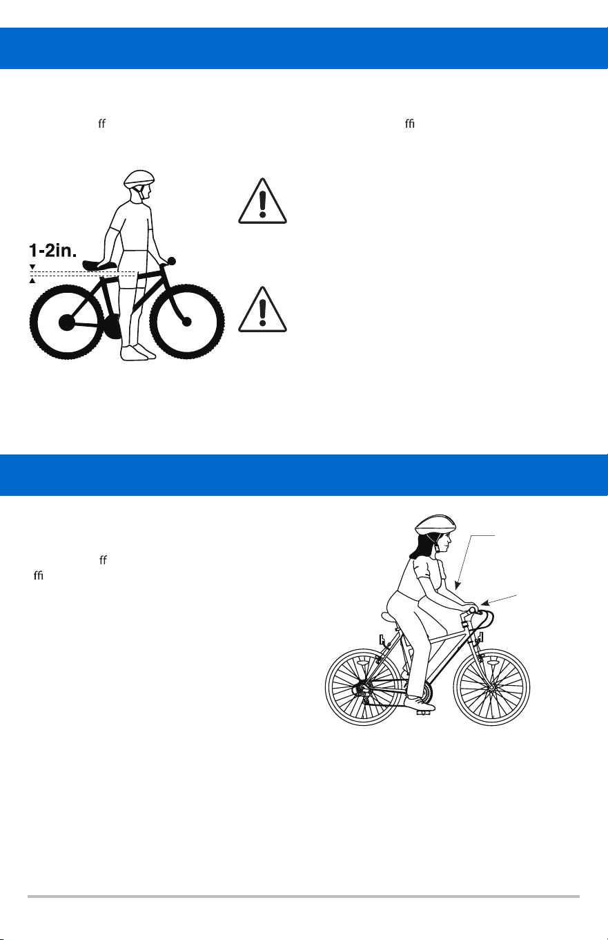
Correct Frame Size
Riding Position
When selecting a new bicycle, the correct choice of frame size is a very important safety consideration.
The ideal clearance will vary between types of bicycles and rider preference. This makes straddling the
frame when o
the saddle easier and safer in situations such as sudden tra c stops. Women can use a
man’s bicycle to determine the correct size to use.
THERE SHOULD BE A CLEARANCE OF NO LESS
THAN 1-2 INCHES BETWEEN THE GROIN AREA
OF THE INTENDED RIDER AND THE TOP TUBE OF
THE BICYCLE, WHILE THE RIDER STRADDLES THE
BICYCLE WITH BOTH FEET FLAT ON THE GROUND.
THE SEATPOST “MINIMUM INSERTION” /
“MAXIMUM HEIGHT” MARK SHOULD NOT BE
VISIBLE WHEN THE SEAT POST IS INSERTED INTO
THE SEAT MAST OF THE BIKE. DO NOT RAISE THE
SEAT POST BEYOND THIS MARK. THE SEAT POST
OR FRAME MAY BREAK CAUSING YOU TO LOSE
CONTROL AND FALL. ALWAYS CHECK TO MAKE
SURE SEAT POST ADJUSTING MECHANISM IS
TIGHTENED SECURELY BEFORE RIDING.
SADDLE HEIGHT
In order to obtain the most comfortable riding
position and o er the best possible pedaling
e ciency, the seat height should be set correctly
in relation to the rider’s leg length. The correct
saddle height should not allow leg strain from
overextension, and the hips should not rock from side
to side when pedaling. While sitting on the bicycle
with one pedal at its lowest point, place the ball of
your foot on the pedal. The correct saddle height will
allow the knee to be slightly bent in this position.
REACH
To obtain maximum comfort, the rider should not overextend his or her reach when riding. There should
be a slight bend in the rider’s elbows. Refer to the section regarding seat and seat posts to learn how to
adjust the seat post height.
Arms not
overextended
Handlebar stem
height about the
same as
seat height
Pedal at
bottom position
i
i
11
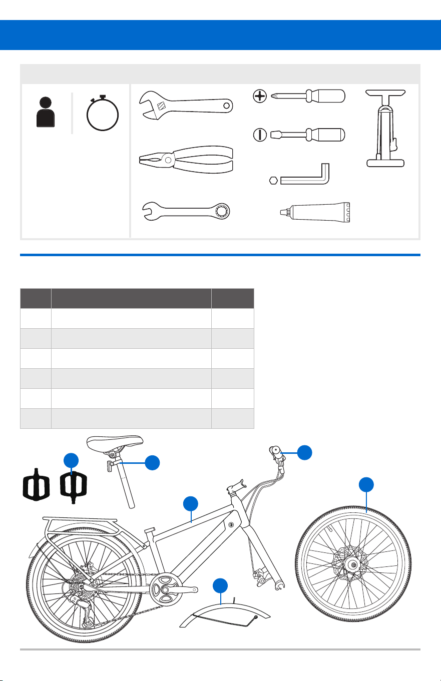
Air Pump
4 & 5 & 6 mm Hex Wrench
Bicycle Lubricant or Grease
Phillips Screwdriver
Standard Screwdriver
10 & 15 mm Open End Wrench
6” Adjustable Wrench
Pliers (with cable cutting ability)
15
min
SETUP TOOLS NEEDED
Model Description
NOTE:
If you have questions
about your ability to
properly assemble this
bicycle, please consult
a professional bicycle
mechanic before riding.
Part Description Qty
1 Frame 1
2 Handlebar/Stem Assembly 1
3 Front Wheel Assembly 1
4 Seat Assembly 1
5 Pedals 2
6 Front Fender 1
PARTS DIAGRAM
3
6
5
4
1
2
12
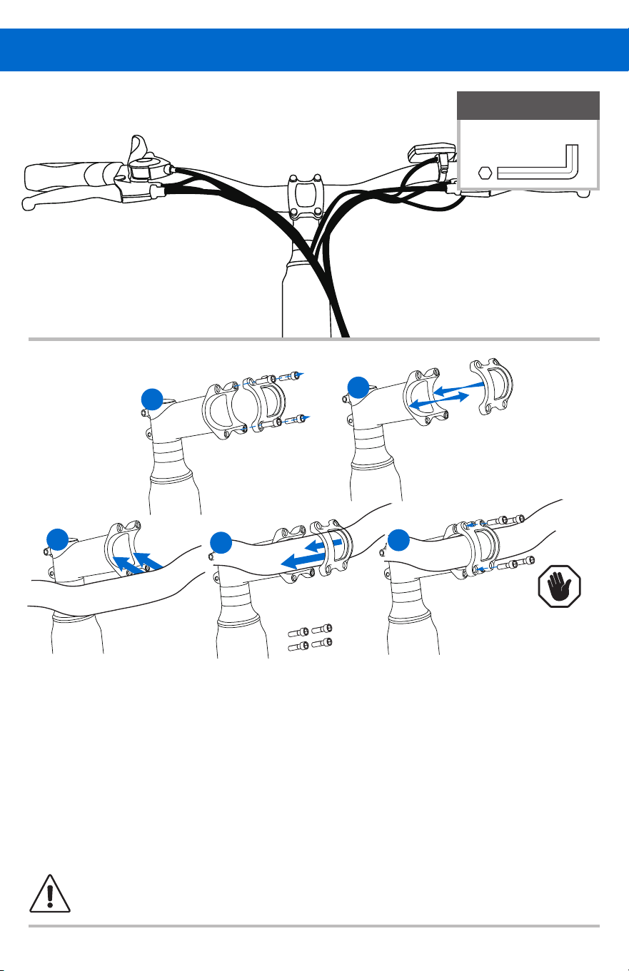
1. Using the hex wrench, remove handlebar clamp bolts and hold them aside.
2. Remove the stem faceplate and hold it aside.
3. Place the handlebar into stem channel.
4. Replace the stem faceplate to hold the handlebar in place.
5. Using the hex wrench, thread the handlebar clamp bolts back in place and tighten them securely.
NOTE: Recommended torque is 15 ft. lbs. (20 Nm)
1. INSTALL HANDLEBARS
Assembly
WARNING! Failure to properly tighten handlebar components may result in loss of control,
serious injury, or death. Always check the handlebar CANNOT move and is secured to the frame
before riding the bicycle.
CAUTION
Ensure the gap
is even on top
and bottom
between the
faceplate and
stem body.
REQUIRED
4mm Hex Wrench
1
2
3
4
5
13
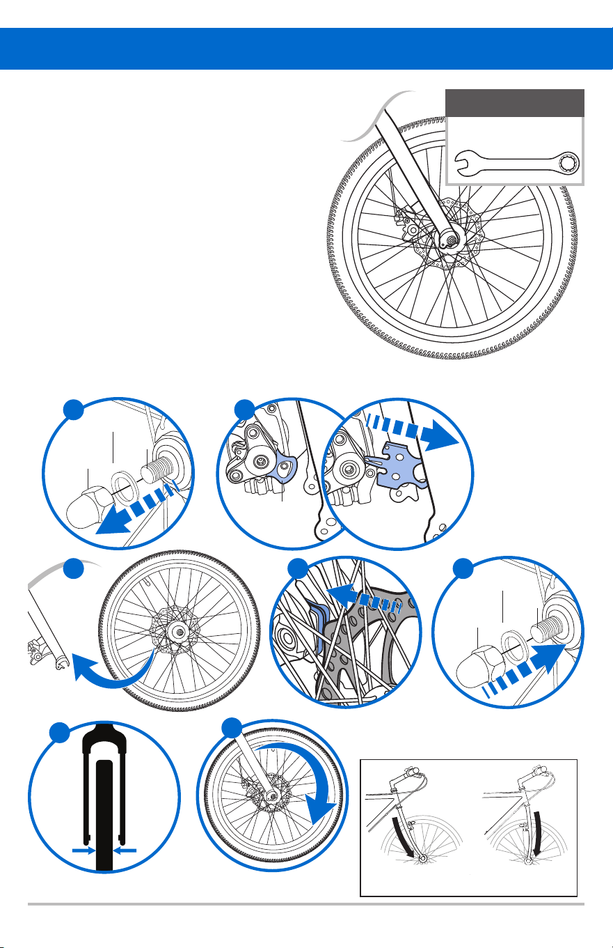
3 4
6
CORRECT
Fork points forward
INCORRECT
Fork points backward
2. ATTACH FRONT WHEEL
1. Remove the washer head nuts and
wheel retainers from the front wheel.
2. Remove the front brake caliper plastic insert.
3. Slide the wheel onto the open ends
of the fork.
4. Align rotor between brake pads.
5. Install a wheel retainer onto each end of the
axle then install the washer head nut loosely.
6. Center the wheel in the fork. Using a 15mm
open end wrench, tighten the axle nuts securely,
alternat
ing from one side to the other to center
the wheel. NOTE: Recommended torque is
16-20 ft. lbs. (22-27 Nm)
7.
Spin the wheel to make sure that it is centered in the
fork and does not wobble. If the wheel is not centered,
loosen the nuts and try again.
Assembly
BRAKE CALIPER
PLASTIC INSERT
2
WASHER
HEAD NUT
AXLE
WHEEL
RETAINER
WASHER
HEAD NUT
AXLE
WHEEL
RETAINER
7
REQUIRED
15mm Open End
Wrench
5
1
14
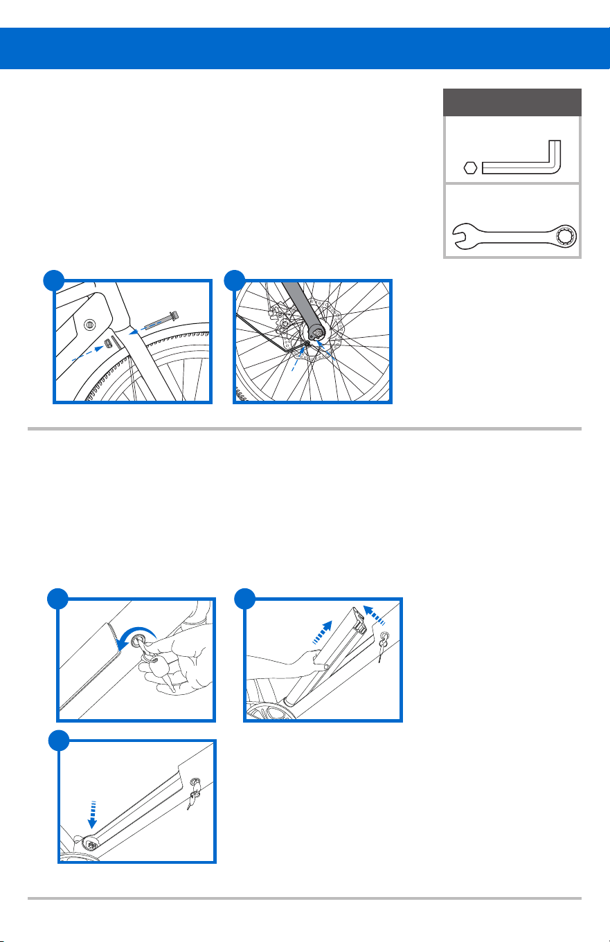
3. INSTALL SEAT ASSEMBLY
1. Open the quick release lever on the seat tube.
2. Insert the seat post into the seat tube past the minimum insertion line.
3.
Close the quick release lever (Fig 3.1).
Assembly
Fig 3.1
NOTE
If the seat post is not secure
enough, open the quick release
lever, slightly turn adjustment
nut, then close quick release
lever to test again.
TENSION
ADJUSTING
NUT
QUICK
RELEASE
BINDER
BOLT
QUICK
RELEASE
SEAT POST
LEVER
15
SEAT CLAMP
SEAT CLAMP NUTS
TORQUE REQUIREMENT
8.9-10.3 FT. LBS.
SEAT HEIGHT:
The correct seat height should not allow leg
strain from overextension, and the hips should
not rock from side to side when pedaling. The
correct saddle height will allow the knee to be
slightly bent. To obtain maximum comfort, the
rider should not overextend his or her reach
when riding. There should be a slight bend in
the rider’s elbows.
Assembly
SEAT ANGLE:
The top of the seat should be parallel to the ground
or comfortable to the rider.
Seat angle adjustment:
1. Use the adjustable wrench to loosen the
seat clamp nut.
2. Correct the seat angle to desired position.
3. Retighten the seat clamp nuts securely.
Recommended torque is 8.9-10.3 ft. lbs (12-14 Nm).
4. Check for tightness by attempting to twist the seat along
with rocking it up and down. If the seat is loose, retighten
the clamp nuts and binder bolt securely.
16
Recommended torque is
15-18 ft. lbs. (20-24 Nm).
Assembly
REQUIRED
(5) Pedals
15mm Open End
Wrench
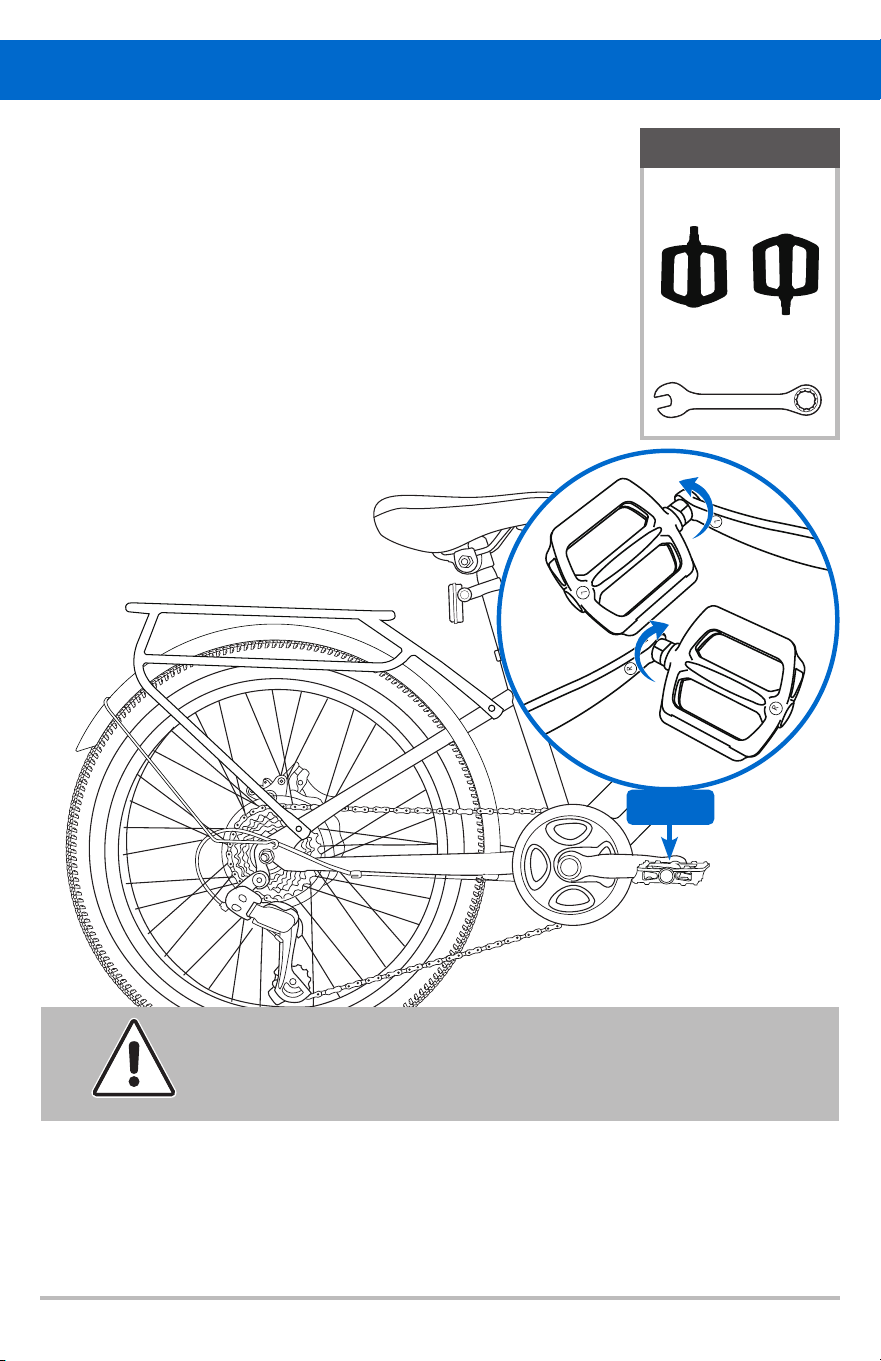
4. ATTACH PEDALS
1. Match the right pedal (R) with the right
crank arm. Tighten by hand
clockwise.
2. Match the left pedal (L) with the left
crank arm. Tighten by hand
counter-clockwise.
3. Using a 15mm Open End Wrench,
tighten securely.
Fig 4.1
WARNING!
Improperly installed and tightened pedals can work loose, damaging the
bicycle and causing possible serious injury or death to the rider.
17
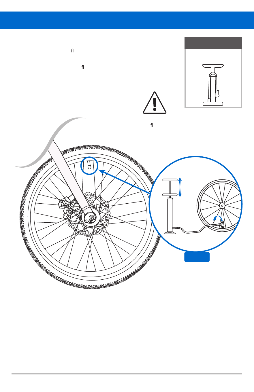
WARNING!
Never in ate a tire
beyond the maximum
pressure marked on the
tire’s sidewall.
5. INFLATE TIRES
Using a manual air pump, in ate the tires after assembly.
1. Attach nozzle to tire valve.
2. Pump up and down to in
ate tire
Assembly
REQUIRED
Manual Air Pump
Fig 5.1
18
2. Remove the mounting screws of the fender arms on both sides of
the fork legs, align the fender arms with the mounting holes, and
then tighten it with the mounting screws.
1. Remove the mounting screw on the fork. Then place the front fender
hanger behind the fork mounting hole and align it.
Insert the mounting screw through from front to back and
pre-tighten the screw. (After adjusting the gap between the
fender and tire to a suitable distance, tighten the screw that
was pre-tightened in the previous step.)
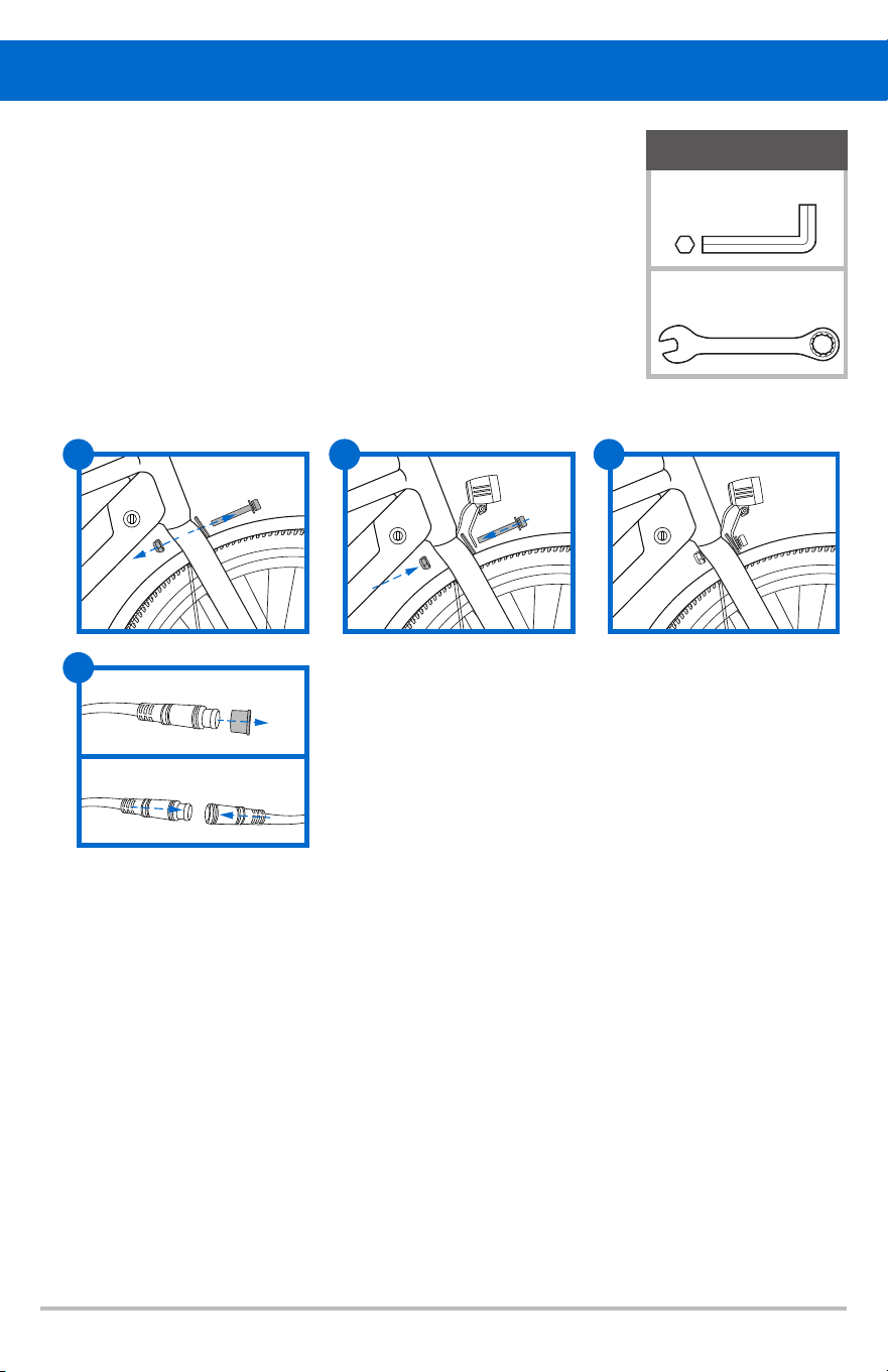
6.INSTALL FRONT FENDER
1. Rotate the key counter clockwise.
2. The battery will pop up automatically. Pull the battery out at the same time.
3. After removing the battery, you should keep the battery compartment clean
and avoid exposure to rain. (After removing the battery, you can carry the individual
battery for charging. lt is essential to store the battery safely when not in use. You can
also charge your battery while it is installed in the bike using the exterior charging port.)
7.REMOVING THE BATTERY
Assembly
REQUIRED
4&5mm Hex Wrench
10mm Open End
Wrench
1 2
2
1
3
19
2.
1. Use a tool to remove the mounting screw on the fork.
Place the headlight bracket on the fork as shown in the f
The order from front to back should be the headlight bracket, the
front fender hanger, and then the fork.
3.
Replace the removed screw and align it to the fork. Pre-tighten the
screw. Then, adjust the gap between the fender and tire, check the
angle of the headlight, and fully tighten the screw.
4.
Remove the dust cover from the connector wire on the bike, then
connect the headlight to the wire.
The headlight is an optional accessory and is not included with your bike.
It needs to be purchased separately. The installation steps are as follows:
8.INSTALL ACCESSORY-HEADLIGHT
Assembly
1
REQUIRED
5mm Hex Wrench
10mm Open End
Wrench
2
3
4
igure.

20
1. Remove the wheel from the bicycle.
2. Deflate the tire completely via the valve. Loosen the tire bead by pushing it inward all the way
around.
3. Press one side of the tire bead up over the edge of the rim. Note: Use tire levers, not a
screwdriver, otherwise you may damage the rim.
4. Remove the tube, leaving the tire on the rim.
5. Locate the leaks and patch using a tube repair kit or replace the tube. Note: Ensure that the
replacement tube size matches the size stated on the tire sidewall and that the valve is the
correct type for your bicycle.
6. Match the position of the leak in the tube with the tire to locate the possible cause and mark the
location on the tire.
7. Remove the tire completely and inspect for a nail, glass, etc. and remove if located. Also inspect
the inside of the rim to ensure there are no protruding spokes, rust or other potential causes.
Replace the rim tape which covers the spoke ends.
8. Remount one side of the tire onto the rim.
9. Using a hand pump , inflate the tube just enough to give it some shape.
10. Place the valve stem through the hole in the rim and work the tube into the tire.
NOTE : Do not let it twist.
11. Using y
our hands only, remount the other side of the tire by pushing the edge toward the center
of the rim. Start on either side of the valve and work around the rim.
12. Before the tire is completely mounted, push the valve up into the rim to make sure the tire can
sit squarely in position.
13.
NOTE: Avoid using tire levers as these can easily puncture the tube or damage the tire.
14. Check that the tube is not caught between the rim and the tire bead at any point.
15. Using a hand pump , inflate the tube until the tire begins to take shape. Check that the tire bead
is evenly seated all the way around the rim. When properly seated, fully inflate the tire to the
pressure marked on the sidewall.
16. Replace the wheel into the frame checking that all gears, brakes and quick release levers are
properly adjusted.
How To Fix A Flat Tire
i
i
it the rest of the tire, rolling the last, most d
cult part on using your thumbs.
ffF
21
NOTE:
Only shift gears while pedaling
SHIFTING GEARS
Shift to a harder gear: Shift to an easier gear:
Press the smaller trigger Press the larger trigger
Operation
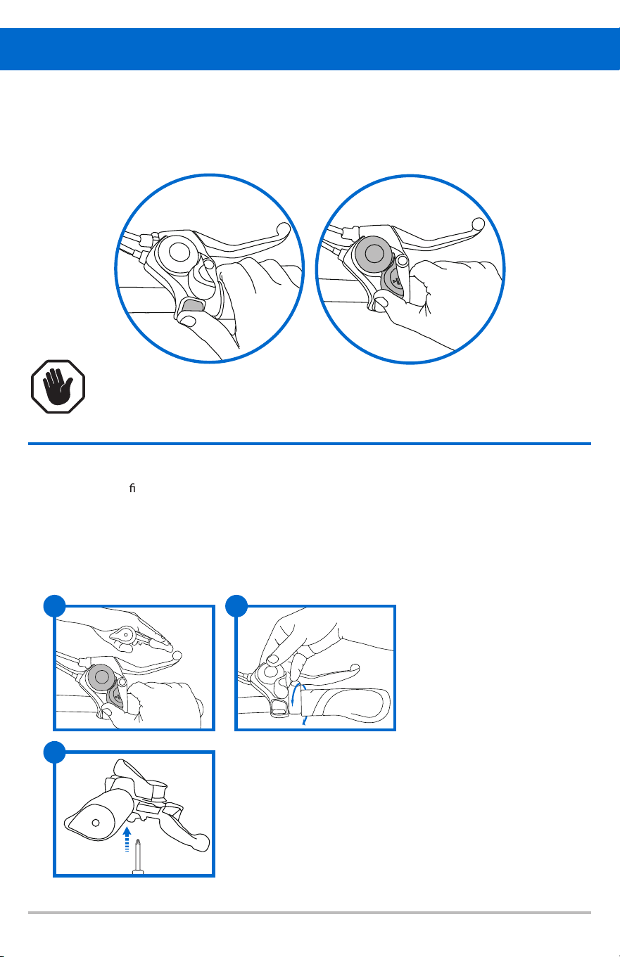
SHIFTER POSITION ADJUSTMENT
1. With index nger on brake lever, test the shifter position.
You should be able to reach both levers easily without losing your grip.
2.
3.
Rotate shifter around the handlebar. Larger trigger should be 0-30º
from vertical.
Tighten clamp bolt using phillips screwdriver. Recommended torque is 4 ft. lbs. (5 Nm)
1 2
3
i
22
DISC BRAKES
1. Always make sure the brakes are working correctly before you ride the bicycle.
2. Allow brake components to cool before attempting to adjust the brakes.
The calipers and rotor will become hot when the brakes are operated. Do not touch them while
riding or immediately after dismounting from the bicycle. You may get burned.
3. If noise occurs when brakes are operated, it may indicate that the brake pads have worn down
to their usage limit. After checking that brake system has cooled down su ciently, check the
brake pad thickness (0.5mm minimum thickness required). Replace brake pads if necessary.
4. Be careful not to allow any oil or grease to get onto rotor or brake pads.
5. Check the brake cable for rust and fraying. Replace cable immediately if such problems
are found. If this is not done, the brakes may not work correctly.
6. WET WEATHER WARNING: Required braking distance will be longer during wet weather
.
Re
duce your speed and apply the brakes early and gently. If road surface is wet, tires will skid more
easily. If the tires skid, you may lose control of the bicycle.
CAUTION: Disc brakes have a burn-in period, and the braking force will gradually
increase as the burn-in period progresses. Make sure that you are aware of any such in
increases in braking force when using the brakes during the burn-in period. The same thing
will happen when the brake pads or rotor are replaced.
Brake is correctly adjusted when:
- The brake pads do not drag on the rotor when the brake is open.
- When the brake is applied, the brake pads contact the rim before the brake lever reaches 1/3 of
the way to the handlebar.
WARNING! DISC GETS HOT! SEVERE INJURY COULD RESULT FROM CONTACT WITH
THE HOT DISC. ALLOW DISC TO COOL COMPLETELY BEFORE TOUCHING.
Operation
BRAKE ADJUSTMENT :
CENTERING THE BRAKE
First determine if the wheel is centered. Look at the space between the
tire and the frame on either side. If it is not even, loosen the wheel axle
nuts and center the wheel, then proceed to center the brake.
If the brake is not centered, look at the disc brake caliper for centering
adjustment screws at the center of the brake pad on either side. Looking
down into the brake where the brake pads contact
the disc rotor,
determine which side needs to move away or towards the disc. Turn the
centering adjustment screws so that there is about 1/32 of an inch of
clearance on either side of the disc rotor. Spin the front wheel and listen
for any rubbing noise or excess friction. Repeat the steps until the brake
is centered.
Brake is correctly adjusted when:
- The brake pads do not drag on the rotor when the brake is open.
- When the brake is applied
, the brake pads contact the rim before
the brake lever reaches about 1/3 of the way to the handlebar.
iff
23
E-Bike Console Functions
: Press the power button for 2-3 seconds to power on. While the bike is powered
of inactivity.
Pedal Assist System (PAS) switching:
Boost mode:
When the power is on, press and hold the boost button for 2-3 seconds to activate
the boost mode. The bike will travel at an even speed of 3.7mph (6km/h). Braking, pressing the
accelerator, or switching gears will exit the boost mode.
Battery display:
is low and needs to be charged soon.
Gear indicator
Power indicator
PAS "+" button, light button
PAS "_" button, booster button
Light indicator
Function Mode:
Three Riding Mode: Throttle-Assisted Mode, Pedal-Assisted Mode, Bicycle Mode.
Throttle Assisted Mode:When you turn the bike on, the assist level will be at 0. Press the up
arrow ( ) on the controller to increase the level of assist. Use the down arrow ( )to reduce
the level of assist. As you increase the level of assist, the speed of the bike will increase. Press the
throttle lever to engage the motor and move the bike.
+
Pedal-Assist Mode:When you turn the bike on, the assist level will be at level 0. Press the up
arrow ( ) on the controller to increase the level of assist. Use the down arrow ( ) to reduce
the level of assist. As you increase the level of assist, the speed of the bike will increase. As you start
to pedal, the motor will automatically engage. When you stop pedaling, the motor will automatically
disengage.
Bicycle Mode:
+
i
on, press and hold for 2-3 seconds to power of .
f
The bike will automatically shutdown after 10 minutes
There are f
ve PAS levels in total. The default is 0
_
_
when the machine is turned on, which has no power output. Press the PAS “+” or PAS “-” button to
adjust the assist level up or down. (Power output will only be available when the bike is in a PAS level).
When the battery display has one bar left or begins to f ash, it means the batteryl
When riding while the bike is of or in neutral, the motor has no power output.f

24
Battery Information
Before using the charger, locate the voltage selector switch (li-ion chargers only) on the back of the
charger. Select either 115 volts or 230 volts depending on your country of residence. Using the wrong
voltage setting will permanently damage the charger and/or electrical components on the electric
bicycle.
1. Use the matching charger.
electrical socket.
3. A red light indicates that the battery is charging.
4. A green light indicates that the battery is fully charged.
5. The Key lock position will vary from model to model.
6. The battery is removable. The battery can be charged while attached to the E-Bike or
pulled out and charged separately.
BATTERY ASSEMBLY
voltage of the charger is consistent with the battery voltage and check whether the
charger input voltage is consistent with the grid voltage.
output plug into the charging port. Plug the electrical power plug into the 100-240V
50/60Hz AC Power Supply. Be sure to keep the input plug in contact with the AC
outlet.
output plug connected with e-bike shall be pulled out. Do not leave the charge
plugged in.
CHARGING THE BATTERY
1. Do not place anything on the battery and charger when charging, otherwise the
charger may overheat and cause serious damage.
2. Only use the charger supplied by the original factory to charge the battery. If you
3. You can charge your battery at any time if the battery loses power.
4. If you do not use or charge your battery for an extended period of time, battery
performance will decrease. If you do not plan to ride your bike for an extended period
of time it is recommended that you plug in and charge the battery every 4-6 weeks.
5. Protection can help your battery maintain about 80% of its capacity after more than
500 cycles. However, decline is inevitable.
6. If the battery remains uncharged for a long time, it will lead to permanent loss of
performance.
7. If you want to store your battery for an extended period, please store and discharge it
in a cool and dry place.
8. Keep the temperature between 32 F-113 F and avoid direct sunlight. Take the battery
out for charging every 30 days.
9. Do not intentionally short-circuit the battery. This will cause very serious damage
and void the warranty.
10. Dispose of your batteries responsibly. Research local recycling regulations.
11. If you have questions about battery use, maintenance, or storage, please contact
customer service.
12. Only use the battery supplied with this electronic bike.
13. Never charge a lithium battery unsupervised.
PRECAUTIONS FOR BATTERY PROTECTION
o o
i
i
i
i
i
Insert the round plug into the E-bike f
irst and then insert the charger plug into the
2.
When using the charger for the f1. rst time, carefully check whether the rated output
When charging, f
2.
rst put the charger in a ventilated place, then insert the charger
After charging, the input plug of the charger should be pulled out f
rst, and then the
3.
use a d ferent charger your battery will be disqualif ed from warranty.
f
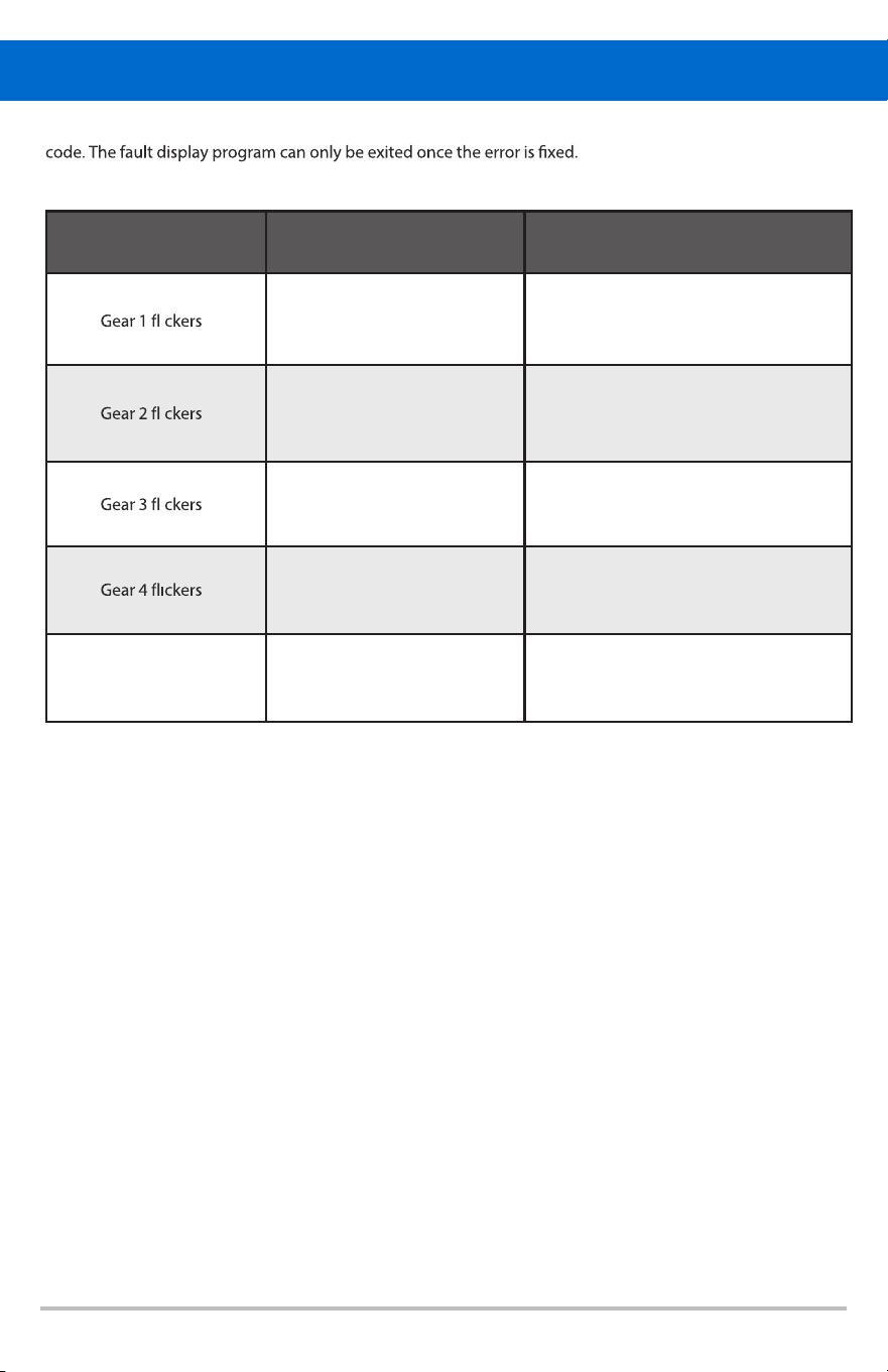
Error Codes
Current abnormal
Throttle abnormal
Motor Phase missing
Motor Hall abnormal
Error Information Troubleshooting Solution
Check controller connection cable, if
connection cable is normal, replace
controller.
Check throttle connection cable, if
connection cable is normal, replace
throttle.
Check motor connection cable, if
connection cable is normal, replace
motor.
Check motor connection cable, if
connection cable is normal, replace motor.
Check display connection cable, if
connection cable is normal, replace
display.
Abnormal communication
between display and controller
25
Display Troubleshooting Guidance
When the e-bike electric control system fails, the display will show the error
After the fault occurs, the e-bike will not continue working.
i
i
i
i
All gear lights f ashingl

26
ROUTINE MAINTENANCE
Correct routine maintenance of your bike will ensure a longer life for your bike
and safer ride for you. The more you ride, the more frequently maintenance
will be required. We recommend you take your bike to a professional bicycle
mechanic to have maintenance performed at least once a year.
SERVICE CHECKLIST
Frequency Task
Before Every Ride Check wheel and pedal tightness
Check tire pressure
Check brake operation
Check wheels for loose spokes or loose axle nuts
Make sure all fasteners are tightened securely
After Every Ride Quick wipe down with damp cloth
WHEEL INSPECTION:
It is most important that wheels are kept in top condition. Properly maintaining your
bicycle’s wheels will help braking performance and stability when riding. Be aware of
the following potential problems:
• Dirty or greasy rims:
or greasy materials. When cleaning, use a clean rag or wash with soapy water,
rinse and air dry. Don’t ride while they’re wet. When lubricating your bicycle,
don’t get oil on the rim braking surfaces.
• Wheels not straight:
of true. If wheels are not straight, they will need to be adjusted. This is quite
• Broken or loose spokes:
Check that all spokes are tight and that none are missing or damaged.
Caution: Such damage can result in severe instability and possibly an accident
if not corrected. Again, spok
e repairs are best handled by a mechanic.
• Loose hub bearings:
Caution: If there is movement between the axle and the hub, do not ride the
bicycle. Adjustment is required.
• Axle nuts:
Check that these are tight before each ride.
Maintenance
crooked or out
Caution: These can render your brakes ineffective. Do not clean them with oily
Lift each wheel of the ground and spin them to see if they are
f
dif ficult and is best left to a professional bicycle mechanic.
Lift each wheel off the ground and try to move the wheel from side to side.

27
TIRE INSPECTION:
Tires must be maintained properly to ensure road holding and stability.
Check the following areas:
INFLATION: Ensure tires are inflated to the pressure indicated on the sidewall of
the tire. Improper inflation is the biggest cause of tire failure. Due to
the slightly porous nature of bicycle inner tubes, it is normal for your
tires to lose pressure over time. For this reason, it is critically important
to maintain the proper tire inflation on your bike. Caution: Use a hand
or foot pump to inflate tires. NEVER inflate
tires with an air compressor
at a gas station. This can cause the tubes to over inflate and blowout.
BEAD SEATING: When inflating or refitting the tire, make sure that the bead is properly
seated in the rim.
TREAD : Check that the tread shows no signs of excessive wear or flat spots,
and that there are no cuts or other damage.
Caution: Excessively worn or damaged t
ires should be replaced.
VALVES : Make sure valve caps are fitted and that valves are free from dirt. A
slow leak caused by the entry of the dirt can lead to a flat tire, and
possibly a dangerous situation.
RECOMMENDED TIRE PRESSURES:
The recommended pressure molded on the sidewall of your bicycle tires should match the
following chart. Use this as a general guide.
BMX 35-50 p.s.i.
MTB 40-65 p.s.i.
Road Touring 70-90 p.s.i.
Road Racing
110-
125 p.s.i.
Hybrid/Crossbike
60-100 p.s.i.
Maintenance
REFLECTOR INSPECTION:
of riders in low-light or nighttime environments. Please follow this maintenance guide:
KEEP CLEAN:
REGULAR INSPECTION:
ENSURE THE CORRECT ANGLE:
alcohol, strong cleaners or abrasives to prevent surface damage.
pedals) are intact, free from cracks, fading or loosening.
REPLACE DAMAGED OR MISSING REFLECTORS IN A TIMELY MANNER: Only use replacement
parts that comply with CPSC 16 CFR §1512.16 or equivalent safety standards.
AVOID OBSTRUCTIONS:
PREVENT STRONG SHOCK OR EXCESSIVE VIBRATION:
loosen or break.
KEY INSPECTION AFTER OFF-ROADING: If you often ride on rough ground, please check
also maximizes safety when cycling at night
To ensure cycling safety, please always keep all reflectors clean correctly installed and f rmly
xed. Ref ectors play a crucial role in enhancing vehicle visibility and ensuring the safetyl
Regularly wipe the surface of the ref ector with a soft damp cloth. Avoid usingl
Before each ride, check whether all ref ectors (front, rear, wheels,l
The ref ector should face directly in front or behind avoidingl
tilting up or down, otherwise the ref ective eect will be reduced.
l
Please ensure that the load accessories or soil do not block the ref ectorl
Vibration may cause the ref ector tol
whether the ref ector is still f rm and ef ective after each ride.l
Proper maintenance of ref ectors not only helps comply with regulatory requirements, butl

28
Problem Cause Solution/Prevention
Gear shifts not
working properly
Derailleur cables sticking/stretched/
damaged
Lubricate/tighten/replace cables
Derailleur not adjusted properly Adjust derailleur
Indexed shifting not adjusted Adjust indexing
Slipping chain
Worn/chipped chainring or
freewheel sprocket teeth
Replace chainring, sprockets and chain
Chain worn/stretched/sti
link Replace chain / lubricate or replace link
Non-compatible chain/chainring/
freewheel
Seek advice at a bicycle shop
Chain jumping
o freewheel
sprocket or
chainring
Chainring out of true Re-true if possible or replace
Chainring Loose Tighten mounting bolts
Chainring teeth bent or broken Repair or replace chainring/set
Derailleur side-to-side out of
adjustment
Adjust derailleur travel
Constant clicking
noises when
pedaling
Sti chain link Lubricate chain / adjust chain link
Loose pedal axle/bearing Adjust bearings/axle nut
Loose bottom bracket axle/bearings Adjust bottom bracket
Bent bottom bracket/pedal axle Replace bottom bracket/pedal axle
Loose crankset Tighten crank bolts
Grinding noise
when pedaling
Pedal bearings too tight Adjust bearings
Bottom bracket bearings too tight Adjust bearings
Chain fouling derailleurs Adjust chain line
Derailleur jockey wheels dirty/
bi
nding
Clean and lubricate jockey wheels
Freewheel does
not rotate
Freewheel internal pawl pins are
jammed
Lubricate; if problem persists, replace
freewheel
Brakes not
working
e ectively
Brake blocks worn down Replace brake blocks
Brake blocks/rim greasy, wet or
dirty
Clean blocks and rim
Brake cables are binding/stretched/
damaged
Clean/adjust/replace cables
Brake levers are binding Adjust brake levers
Brakes out of adjustment Center brakes
When applying
brakes they
squeal/squeak
Brake blocks worn down Replace blocks
Brake block toe-in incorrect Correct block toe-in
Brake blocks/rim dirty or wet Clean blocks and rim
Brake arms loose T
ighten mounting bolts
Troubleshooting

29
Troubleshooting
Problem Cause Solution/Prevention
Knocking or
shuddering when
applying brakes
Bulge in the rim or rim out of true
True wheel or take to a bike shop for
repair
Brake mounting bolts loose Tighten bolts
Brakes out of adjustment
Center brakes and/or adjust brake block
toe-in
Fork loose in head tube Tighten headset
Wobbling wheel
Axle broken Replace axle
Wheel out of true True wheel
Hub comes loose Adjust hub bearings
Headset binding Adjust headset
Hub bearings colla
psed Replace bearings
QR mechanism loose Adjust QR mechanism
Steering not
accurate
Wheels not aligned in frame Align wheels correctly
Headset loose or binding Adjust/tighten headset
Front forks or frame bent Consult bike shop for frame realignment
Stem wedge bolt not tight Tighten stem bolt
Frequent
punctures
Inner tube old or faulty Replace inner tube
Tire tread/casing worn Replace tire
Tire unsuited to rim Replace
with correct tire
Tire not checked after previous
puncture
Remove sharp object embedded in tire
Tire pressure too low Correct tire pressure
Spoke protruding into rim File down spoke

Please contact our customer service team if you are experiencing problems or need more detailed
information.
After-sales email: support@gotrax.com
TEL:1-844-446-8729
1. Users should operate in accordance with the product manual. In case of any performance fault caused
by production quality, the company shall perform the obligations of the three guarantees in accordance
with the provisions of relevant laws and regulations of the state.
2. The company is still responsible for the after-sales service of the faults beyond three guarantees and
the major components in the three guarantees,but there will be a cost for repair.
3. If the battery needs to be replaced outside of the warranty period, our company will supply the battery
at factory price. To ensure safety and avoid pollution, please follow local regulations for disposing of
batteries.
4. We do not cover physical damage due to negligent care and extreme riding.
5. Replacements and repairs for this electric bike are covered for a period ranging from 90 days to 1 year
following the purchase of the product, depending on the component. Below is a list of components your
bike may have and the duration of their warranty.
Components that make up the vehicle body are covered for 1 year. This includes the frame, rear wheel
motor hub assembly, front fork and neck assembly, rear fork assembly, handlebars, dashboard/console,
stem, spring ca
ble, charging port (note: damage due to dirt/water/mud in port not covered), and bottom
cover (if metal).
Select electronic components are also covered for 1 year. This includes the battery charger, battery pack,
electronic throttle, and electronic brakes.
Components subject to wear are covered for 90 days. This includes handlebar grips, handlebar ends, rear
wheel (note: not the tire), headlight, front fender, rear fender, brake light, front fork cover, folding pedal
rear derailleur, brake levers, bike chains, bells, freewheel, and seats.
Certain components are not covered by the warranty. This includes tires and tubes, brake pads, and
screws.
Warranty
cover, ref ective stickers, bottom cover (if plastic), kickstand, fastener covers, charging port covers, rims,l
For more, visit:
https://cdn.shopify.com/s/files/1/0071/0406/9747/files/g2611manual_Final2.pdf?v=1762667733

