
ASSEMBLY MANUAL / OWNER’S MANUAL
Manual en Español Latino Americano:
http://www.schwinnfitness.com

2
Important Safety Instructions - Assembly 3
Safety Warning Labels / Serial Number 4
Specifications 5
Before Assembly 5
Parts 6
Hardware 7
Tools 7
Assembly 8
Leveling the Bike 14
Moving the Bike 14
Important Safety Instructions - Owner’s 15
Features 16
Console Features 17
Operations 19
Adjustments 19
Workout Mode 20
Pausing or Stopping 20
Service Mode 21
Maintenance 22
Replacing the Batteries 24
Troubleshooting 25
TABLE OF CONTENTS
Nautilus, Inc., (800) NAUTILUS / (800) 628-8458, www.NautilusInc.com - Customer Service: North America
(800) 605-3369, [email protected] | outside U.S. +01-360-859-5180, [email protected] |
Printed in China | © 2011 Nautilus, Inc., All rights reserved. ™ and ® indicate a trademark or registered
trademark. Nautilus, Inc. (www.NautilusInc.com) trademarks include NAUTILUS®, BOWFLEX®, SCHWINN®,
UNIVERSAL® and AIRDYNE® and respective logos. Other trademarks are the property of their respective
owners.
To validate warranty support, keep the original proof of purchase and record the following information:
Serial Number __________________________
Date of Purchase ____________________
To register your product warranty , go to: www.SchwinnFitness.com/register
Or call 1 (800) 605–3369.
If you have questions or problems with your product, please call 1 (800) NAUTILUS (628–8458).

3
!
This icon means a potentially hazardous situation which, if not avoided, could result in death or
serious injury.
Obey the following warnings:
!
Read and understand all warnings on this machine.
Carefully read and understand the Assembly instructions.
• Keepbystandersandchildrenawayfromtheproductyouareassemblingatalltimes.
• Donotinstallthebatteriesintothemachineuntilthetimespeciedintheassemblymanual.
• Donotassemblethismachineoutdoorsorinawetormoistlocation.
• Makesureassemblyisdoneinanappropriateworkspaceawayfromfoottrafcandexposureto
bystanders.
• Somecomponentsofthemachinecanbeheavyorawkward.Useasecondpersonwhendoing
the assembly steps involving these parts. Do not do steps that involve heavy lifting or awkward
movements on your own.
• Setupthismachineonasolid,level,horizontalsurface.
• Donottrytochangethedesignorfunctionalityofthismachine.Thiscouldcompromisethe
safety of this machine and will void the warranty.
• Ifreplacementpartsarenecessaryuseonlygenuinereplacementpartsandhardwaresuppliedby
Nautilus. Failure to use genuine replacement parts can cause a risk to users, keep the machine
from operating correctly and void the warranty.
• Donotuseuntilthemachinehasbeenfullyassembledandinspectedforcorrectperformancein
accordance with the Manual.
• ReadandunderstandthecompleteManualsuppliedwiththismachinebeforerstuse.Keepthe
Manual for future reference.
• Doallassemblystepsinthesequencegiven.Incorrectassemblycanleadtoinjuryorincorrect
function.
• Thisproductcontainsmagnets.Magneticeldscaninterferewiththenormaluseofcertain
medicaldevicesatacloserange.Usersmaycomeintoproximityofthemagnetsintheassembly,
maintenance, and/or use of the product. Given the obvious importance of these devices, such
as a pacemaker, it is important that you consult with your medical provider in connection with the
useofthisequipment.Pleaseconsultthe“SafetyWarningLabelsandSerialNumber”sectionto
determine the location of the magnets on this product.
IMPORTANT SAFETY INSTRUCTIONS
— ASSEMBLY
4
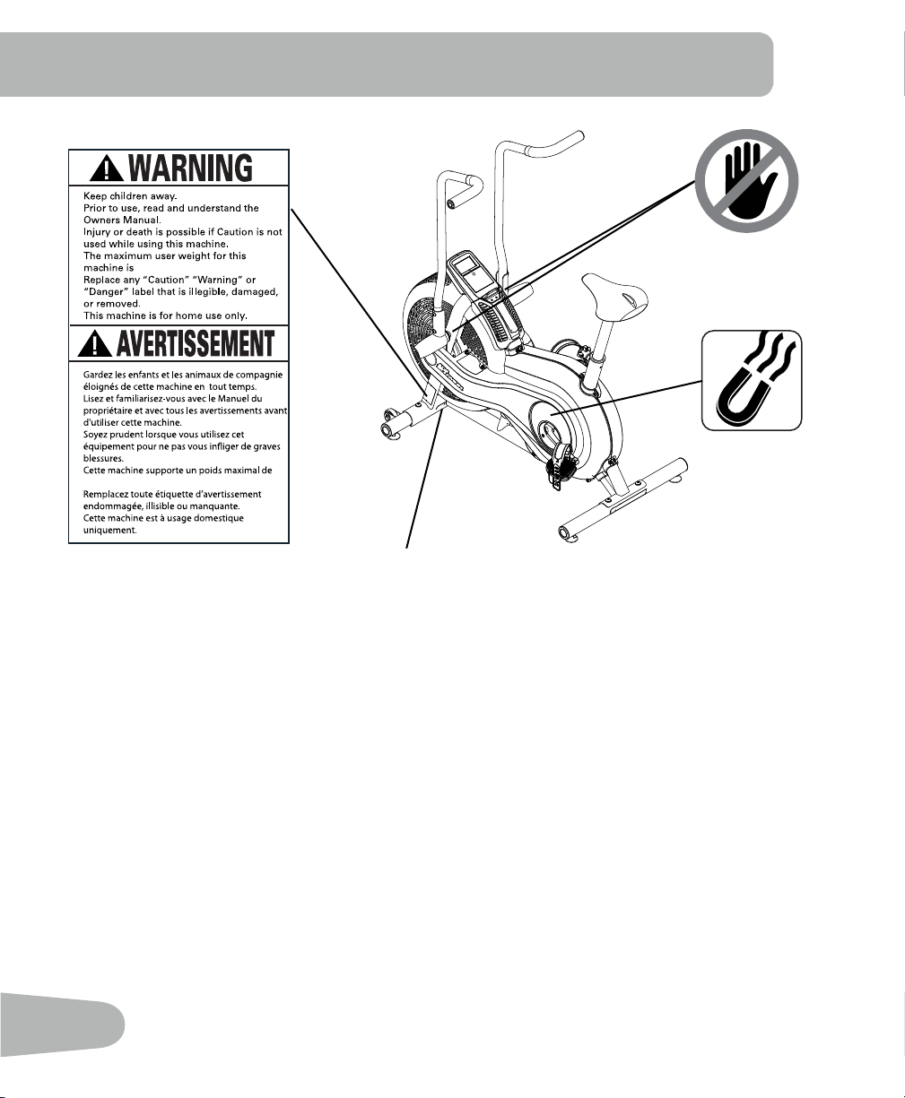
SAFETY WARNING LABELS AND
SERIAL NUMBER
•
•
•
•
•
•
250lbs. (113kg).
•
•
•
•
•
•
250lbs. (113kg).
Serial number
5
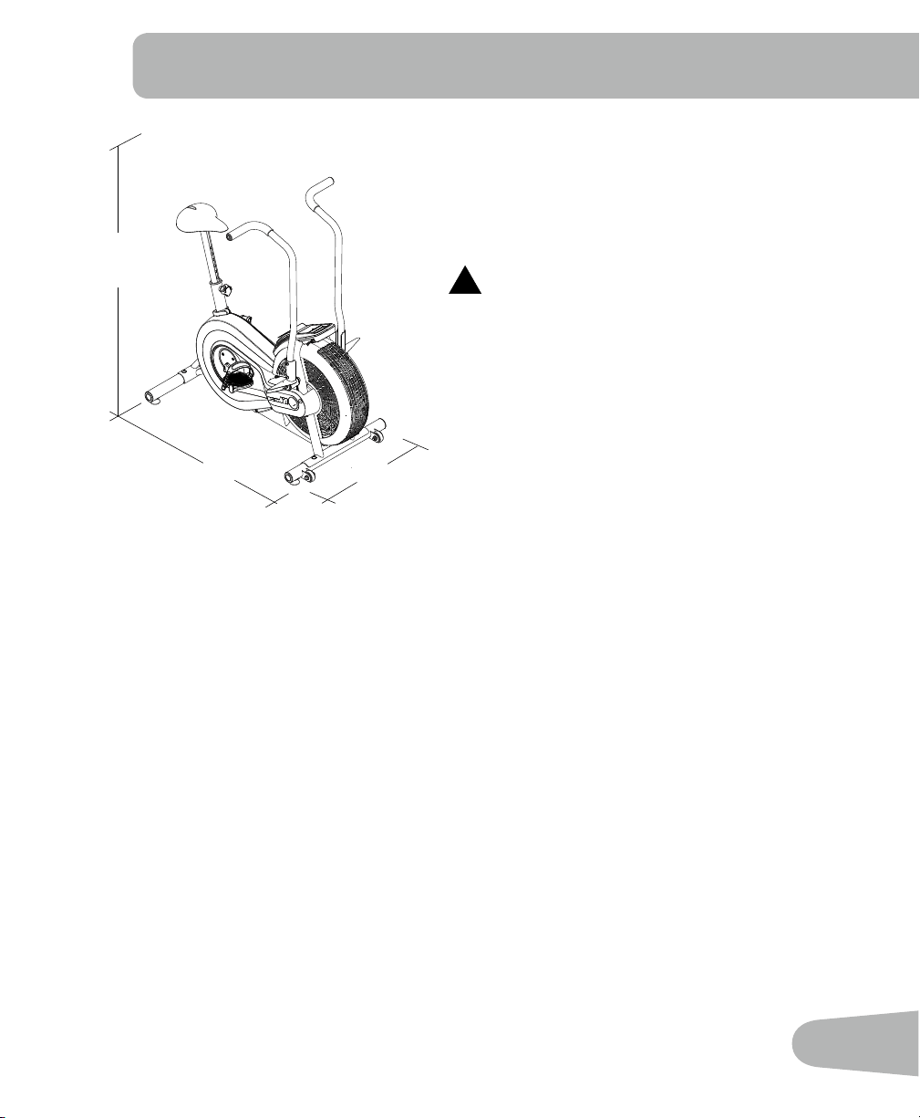
SPECIFICATIONS
50”
(127 cm)
25” (63.5 cm)
46” (117 cm)
Before Assembly
Select the area where you are going to set up and operate your machine. For safe operation,
thelocationmustbeonahard,levelsurface.Allowaworkoutareaofaminimum82”x61”
(2.1mx1.5m).
Basic Assembly Tips
Follow these basic points when you assemble your machine:
1.Readandunderstandthe“ImportantSafetyInstructions”beforeassembly.
2. Collect all the pieces necessary for each assembly step.
3. Using the recommended wrenches, turn the bolts and nuts to the right (clockwise) to tighten,
and the left (counterclockwise) to loosen, unless instructed otherwise.
4. When attaching 2 pieces, lightly lift and look through the bolt holes to help insert the bolt
through the holes.
5.Theassemblyrequires2people.
Maximum User Weight: 250 lbs. (113 kg)
Power Requirements: 2 AA batteries (LR6)
Operational Voltage: 1.0 - 3.3VDC
!
This product, its packaging, and components
contain chemicals known to the State of
California to cause cancer, birth defects, or
reproductive harm. This Notice is provided in
accordance with California’s Proposition 65. If
you would like additional information, please
refer to our web site at
www.nautilus.com/prop65.
6
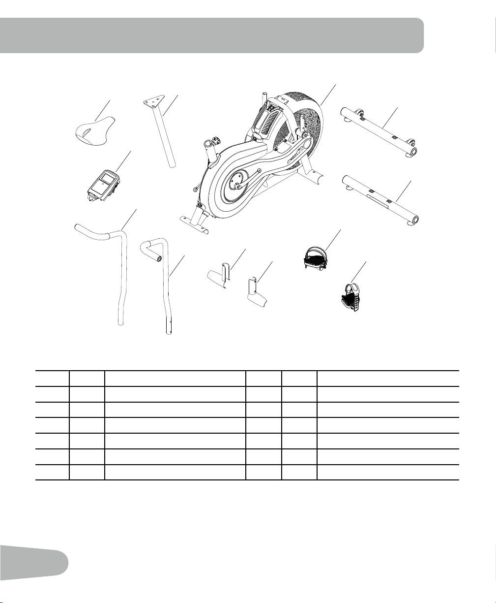
Item Qty Description Item Qty Description
1 1 Main Frame 7 1 Foot Peg, Left
2 1 Front Stabilizer 8 1 Handlebar, Right
3 1 Rear Stabilizer 9 1 Handlebar, Left
4 1 Pedal, Right 10 1 Console
5 1 Pedal, Left 11 1 Seat
6 1 Foot Peg, Right 12 1 Seat Post
1
2
3
4
5
6
7
8
9
10
11
12
PARTS
7
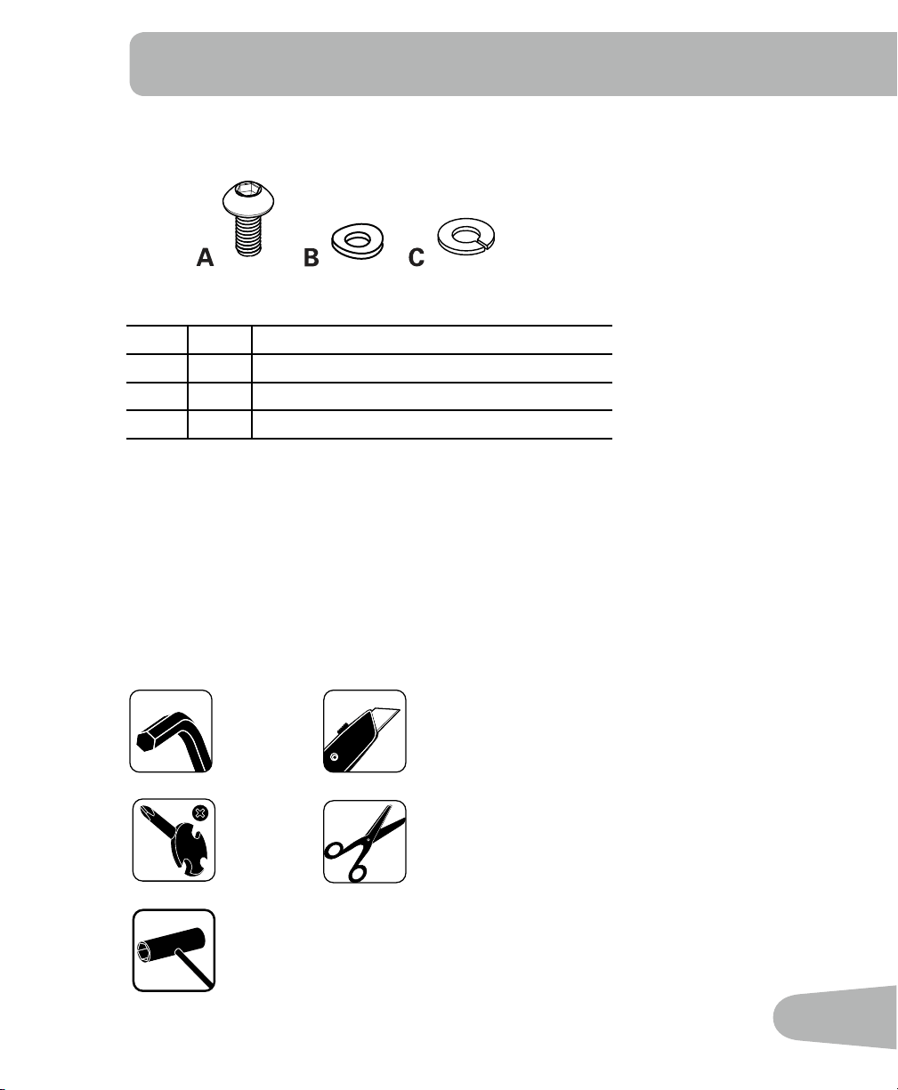
Tools
Included Not Included
6 mm
Item Qty Description
A 8 ButtonHeadHexScrewM8x20
B 8 Curved Washer M8
C 8 Lock Washer M8
(recommended)
HARDWARE / TOOLS
8
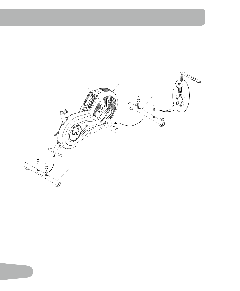
1. Attach Stabilizers to Frame Assembly
ASSEMBLY
1
2
3
C
6 mm
X4
B
A
9
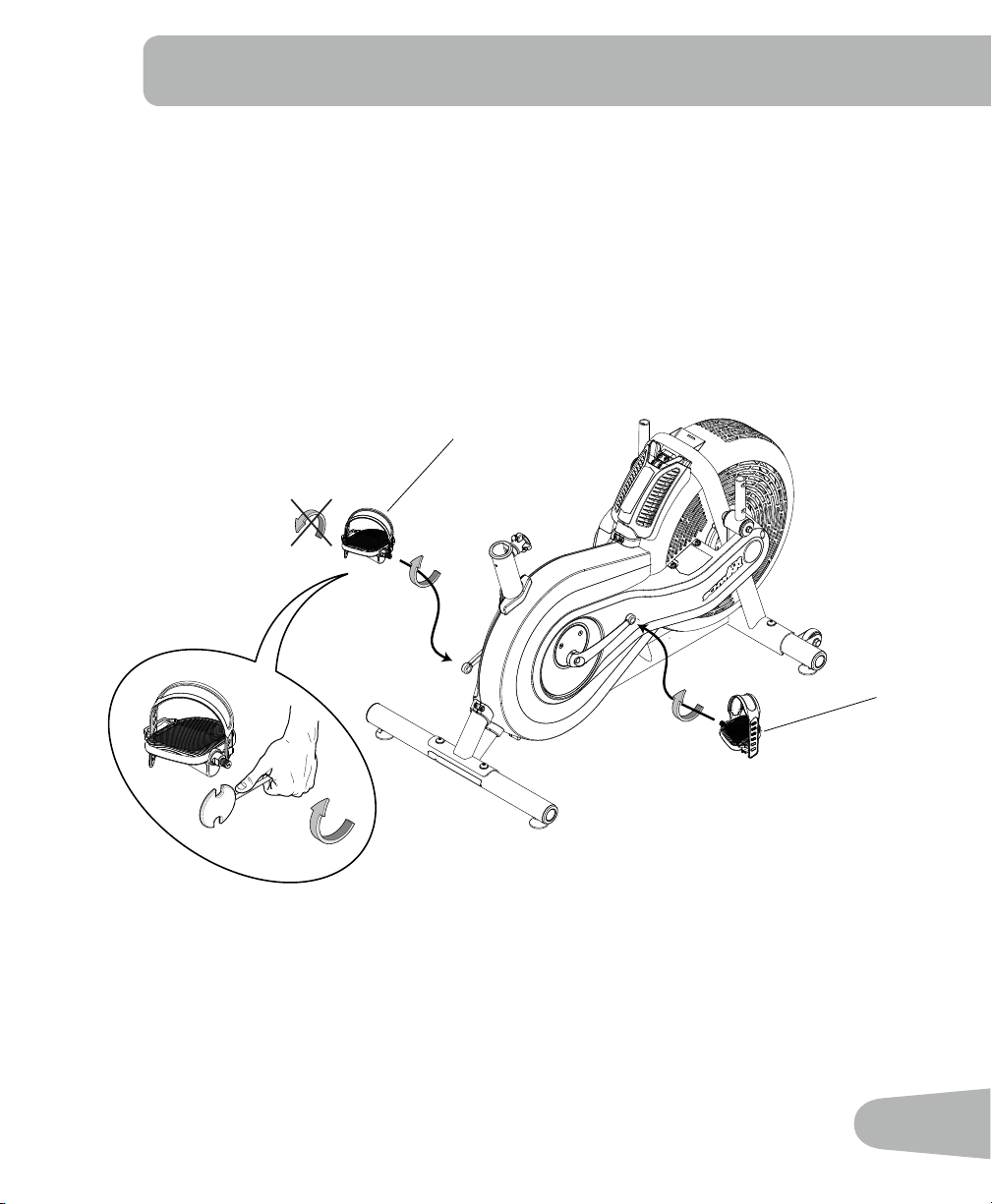
2. Attach Pedals
Note: The Left Pedal is reverse-threaded. Be sure to attach Pedals on the proper side of the
Bike. Orientation is based from a seated position on the bike. The Left Pedal has an
“L”,theRightPedalan“R”.
5
4
10
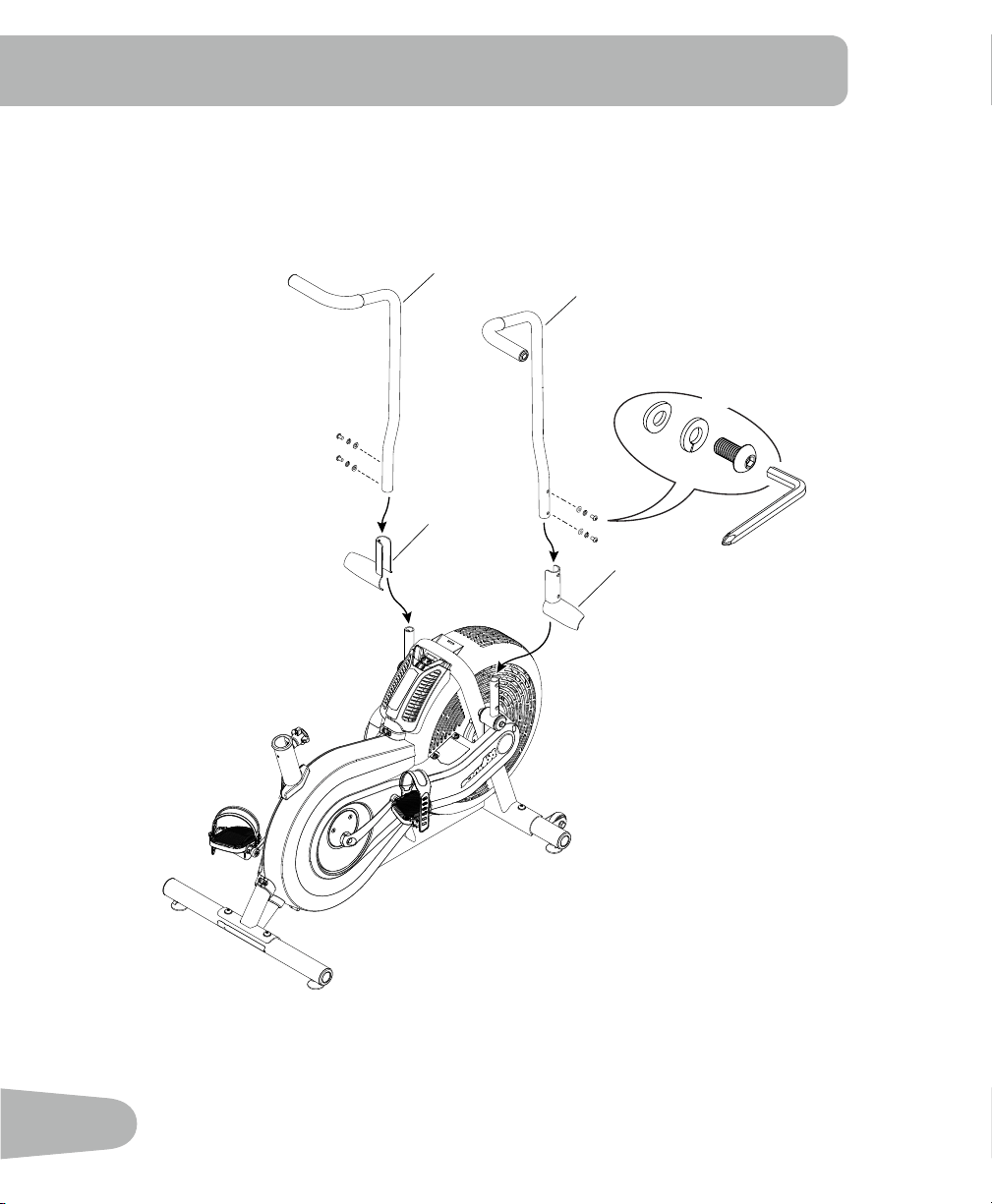
3. Attach Foot Pegs and Handlebar Arms
9
8
6
7
C
B
A
X4
6 mm
11
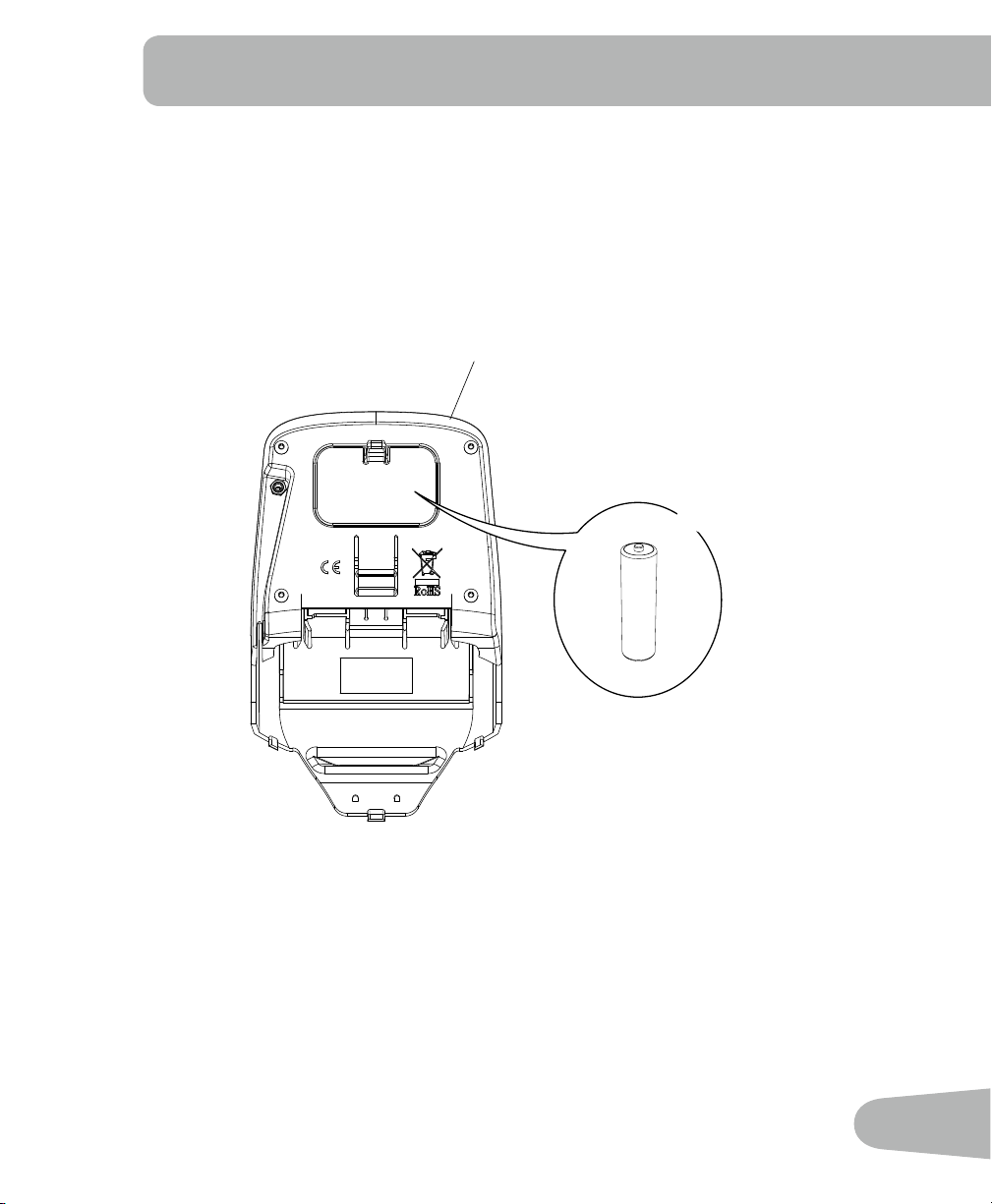
+
-
X2
10
4. Install batteries in Console
Note: The console uses AA size batteries (LR6). Make sure that the batteries point in the
direction of the +/– indicators in the battery bay.
12
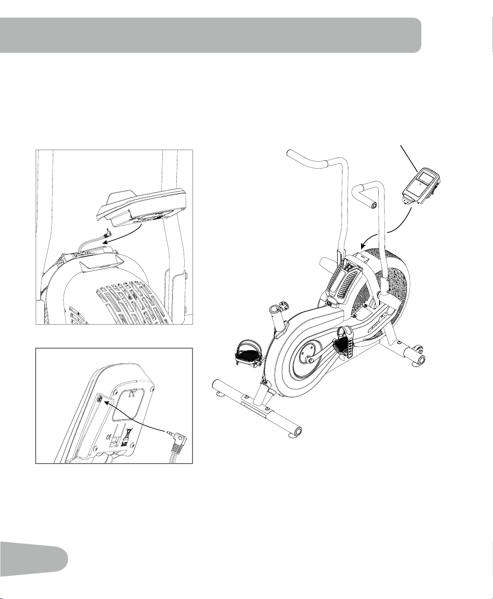
5. Attach the Console and Connect the Console Cable
NOTICE: Do not crimp Console Cable.
10
13
7. Final Inspection
Inspect your machine to ensure that all hardware is tight and components are properly assembled.
Be sure to record the serial number in the field provided at the front of this manual. Refer to the
Safety Warning Labels and Serial Number section of this manual.
!
Do not use or put the machine into service until the machine has been fully assembled and
inspected for correct performance in accordance with the Owner’s Manual.
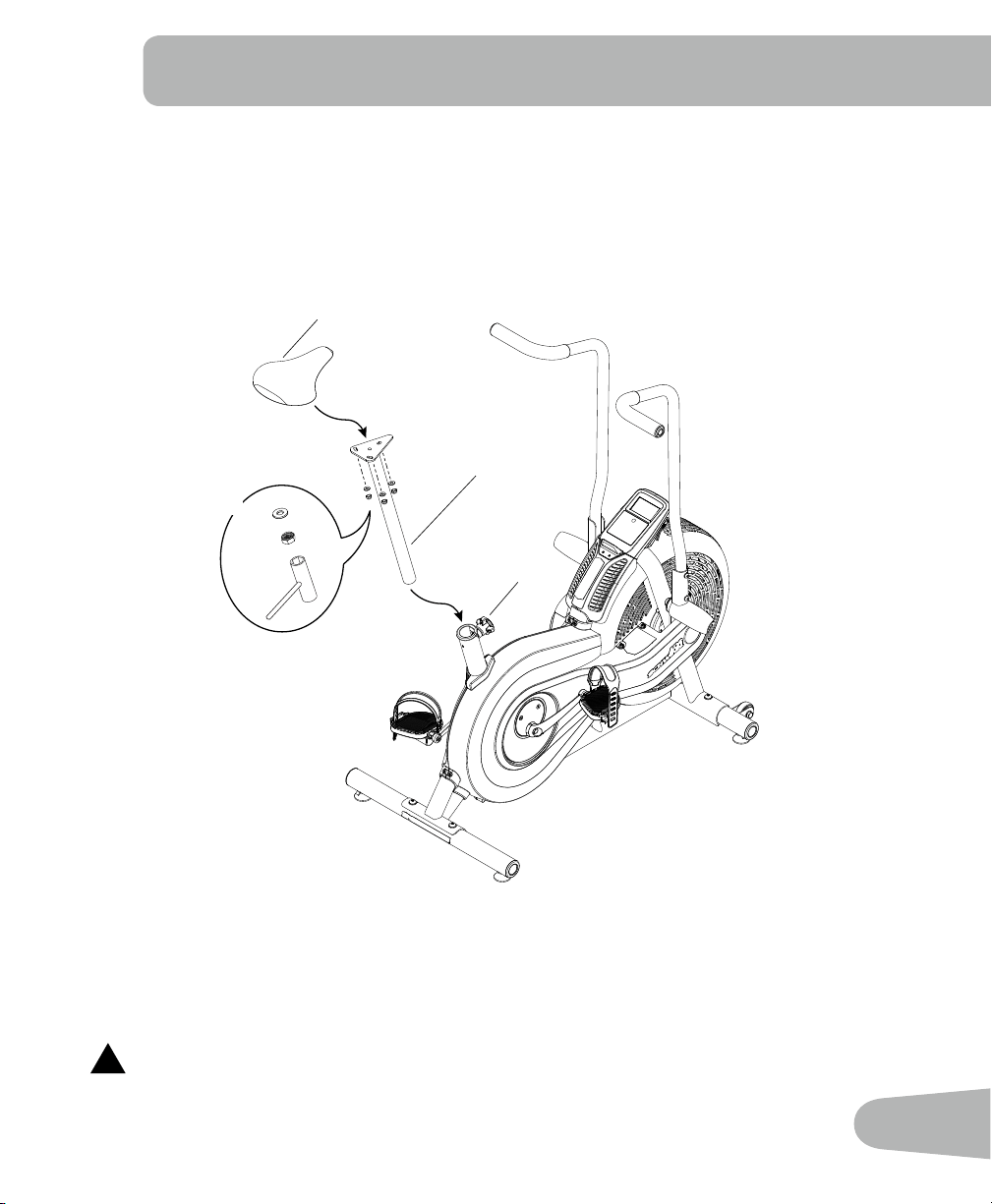
6. Attach Seat to Seat Post and Install on Frame Assembly
Note: Hardware is pre-installed on the seat and not on the hardware card.
NOTICE: Be sure the Seat is straight and tighten the hardware.
Make sure the adjustment knob (12a) engages the holes in the Seat Post.
11
12
12a
X3
14
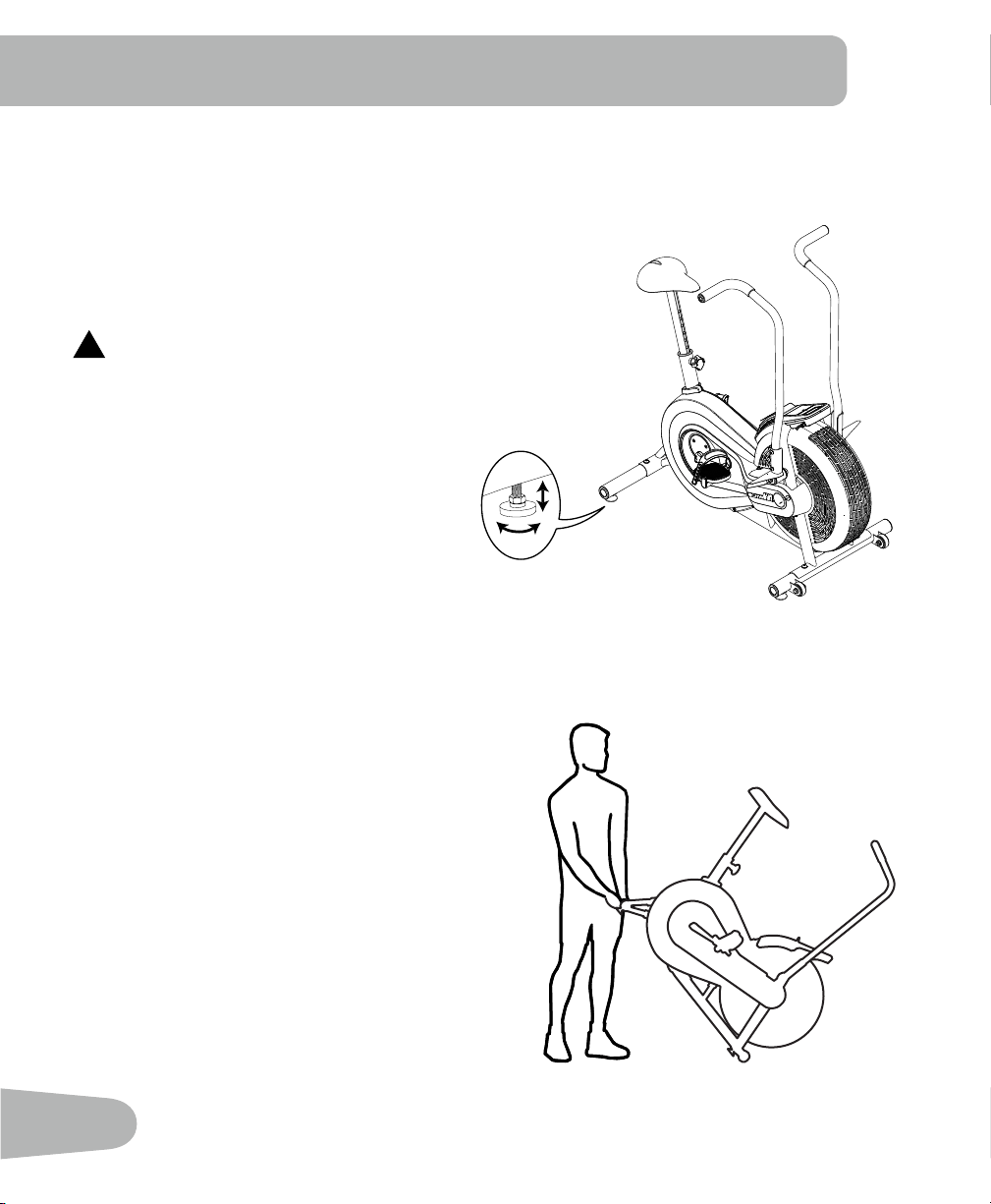
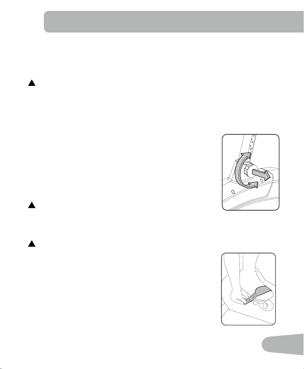
Leveling Your Machine
If your workout area is uneven, you must level your machine.
To adjust:
1. Loosen the upper locking nut.
2. Turn the leveler to adjust the height.
3. Tighten the upper locking nut to lock the leveler.
!
Do not adjust the levelers to such a height that they
detach or unscrew from the machine. Injury to you or
damage to the machine can occur.
Moving Your Machine
To move the machine, carefully lift the rear end of
the machine and slowly push the machine to the
desired location. Be sure to keep the fan assembly
clear of the floor.
NOTICE: Be careful when you move the machine.
Abrupt motions can affect the computer
operation.
BEFORE YOU START

15
!
This icon means a potentially hazardous situation which, if not avoided, could result in death or
serious injury.
Before using this equipment, obey the following warnings:
!
ReadandunderstandthecompleteManual.KeeptheManualforfuturereference.
Read and understand all warnings on this machine. If at any time the Warning stickers become
loose, unreadable or dislodged, contact Nautilus
®
Customer Service for replacement stickers.
• Childrenmustnotbeletonorneartothismachine.Movingpartsandotherfeaturesofthe
machine can be dangerous to children.
• Notintendedforusebyanyoneunder14yearsofage.
• Consultaphysicianbeforeyoustartanexerciseprogram.Stopexercisingifyoufeelpainor
tightness in your chest, become short of breath, or feel faint. Contact your doctor before you
use the machine again. Use the values calculated or measured by the machine’s computer for
reference purposes only.
• Beforeeachuse,examinethismachineforloosepartsorsignsofwear.Donotuseiffoundin
this condition. Monitor the Seat, Pedals, and Crank Arms closely. Contact Nautilus® Customer
Service for repair information.
• Maximumuserweightlimit:250lbs.(113kg).Donotuseifyouareoverthisweight.
• Thismachineisforhomeuseonly.
• Donotwearlooseclothingorjewelry.Thismachinecontainsmovingparts.Donotputngersor
otherobjectsintomovingpartsoftheexerciseequipment.
• Setupandoperatethismachineonasolid,level,horizontalsurface.
• MakethePedalsstablebeforeyousteponthem.Usecautionwhenyousteponandoffthe
machine.
• Disconnectallpowerbeforeservicingthismachine.
• Donotoperatethismachineoutdoorsorinmoistorwetlocations.Keepthefootpedalsclean
and dry.
• Keepatleast24”(0.6m)oneachsideofthemachineclear.Thisistherecommendedsafe
distanceforaccessandpassagearoundandemergencydismountsfromthemachine.Keep
third parties out of this space when machine is in use.
• Donotoverexertyourselfduringexercise.Operatethemachineinthemannerdescribedinthis
manual.
• CorrectlyadjustandsafelyengageallPositionalAdjustmentDevices.Makesurethatthe
Adjustment Devices do not hit the user.
• Exerciseonthismachinerequirescoordinationandbalance.Besuretoanticipatethatchanges
in speed and resistance level can occur during workouts, and be attentive in order to
avoid loss of balance and possible injury.
IMPORTANT SAFETY INSTRUCTIONS
16
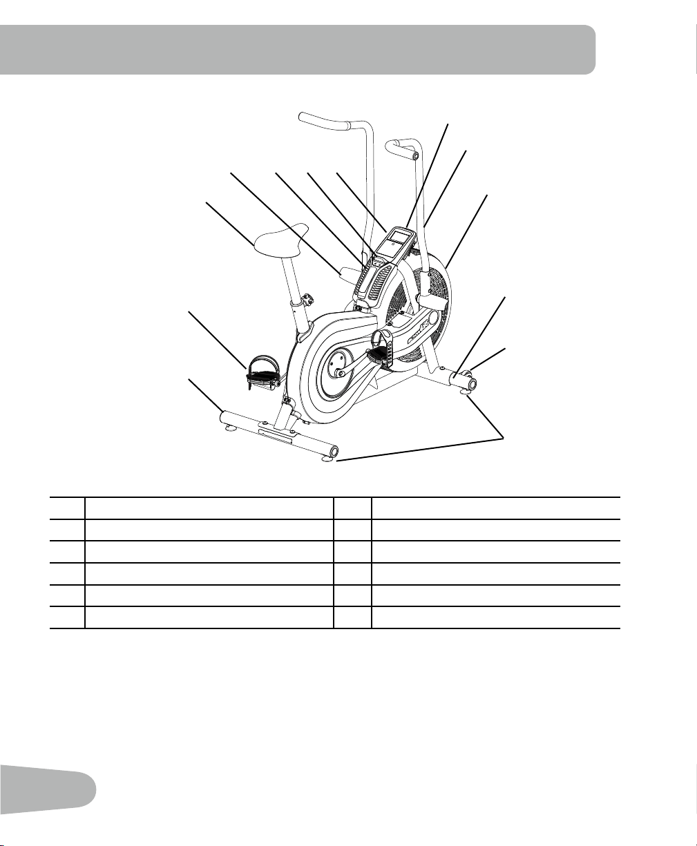
A Console G Pedals
B Handlebars H Adjustable Seat Assembly
C Fan Assembly I Foot Rests
D Stabilizers J Air Vents
E Transport Wheels K Magazine Holder
F Levelers L Battery Bay
FEATURES
A
B
C
D
D
E
F
G
H
I J K L
17
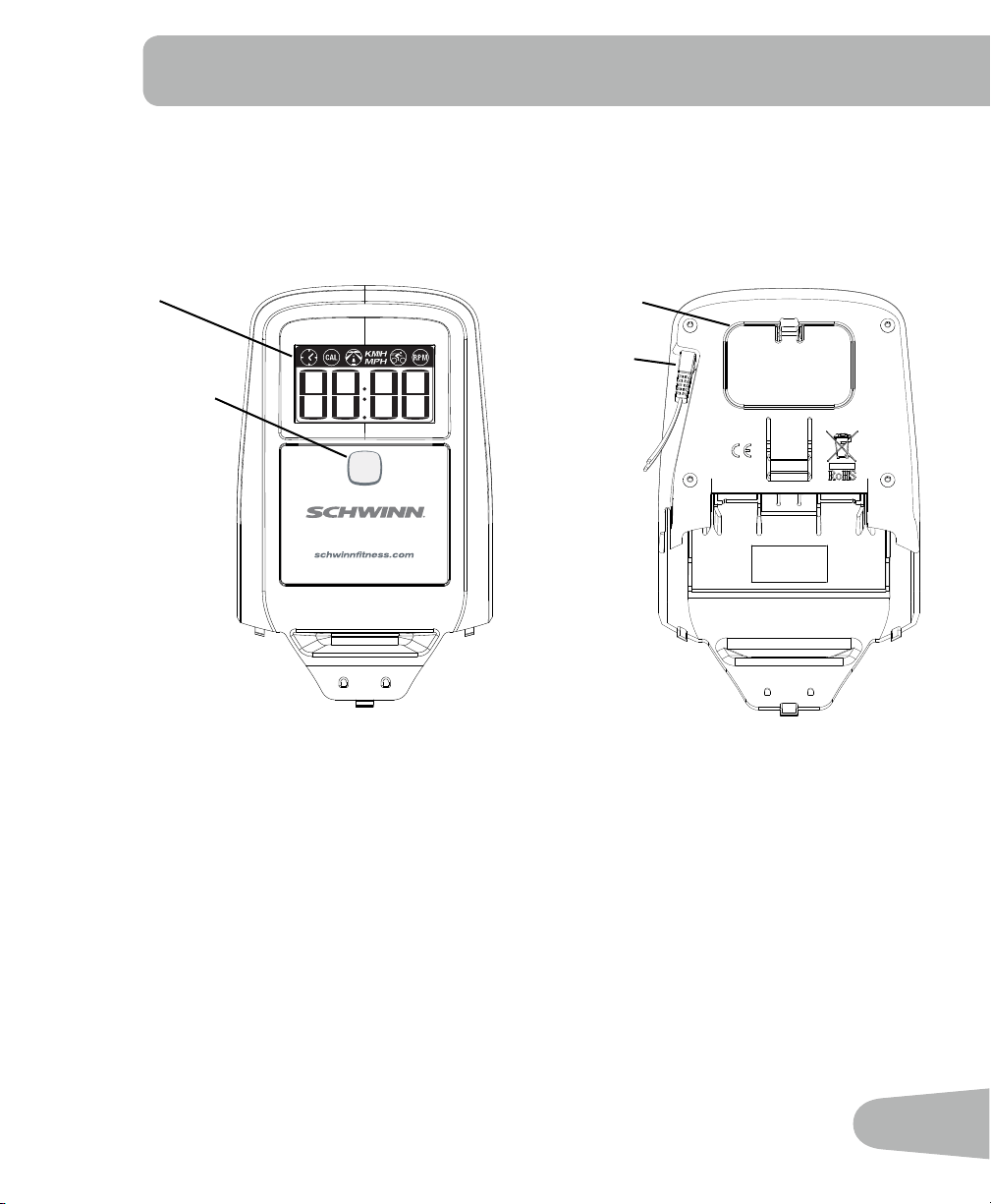
Console Features
The Console provides information about your workout on the display screen. You can also use the
button to get access to information about console settings.
Front Back
START/RESET Push to start, or to stop an active workout and reset the Time to 0:00.
WARNING: If you feel any unusual pain,
shortness of breath or dizziness, consult your physician.
Start Reset
LCD
START/RESET
Cable
connector
Battery bay
18
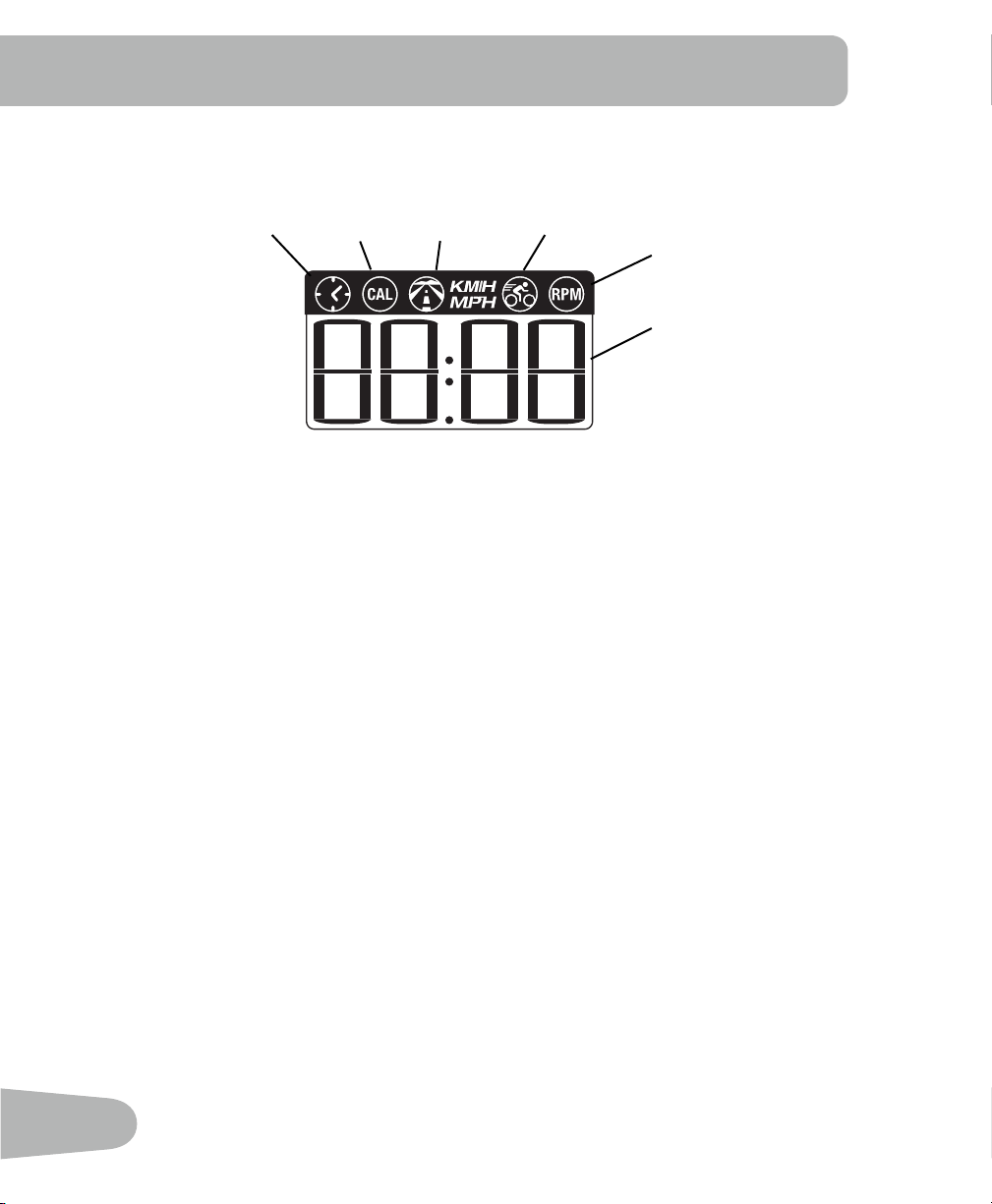
LCD Display Data
Theconsoledisplayshowseachworkoutmeasurementinsequencefor5seconds:
Time
TheTIMEdisplayeldshowsthetimecountintheworkout.Themaximumdisplayis99:59.Ifthe
time count is more, the display starts again at 0:00.
CAL
TheCALdisplayeldshowstheestimatedcaloriesthatyouhaveburnedduringtheexercise.The
maximumdisplayis9999.Ifthecaloriecountismore,thedisplayashes9999.
Distance
The DISTANCE display field shows the distance count (miles or km) in the workout, to two decimal
places—forexample,1.50.Themaximumdisplayis99.99.Ifthedistanceismore,thedisplay
starts again at 0.00.
Note:TochangethemeasurementunitstoEnglishImperialormetric,refertothe“Service
Mode”sectioninthismanual.
Speed
The SPEED display field shows the machine speed in kilometers per hour (km/h) or miles per hour
(mph),toonedecimalplace—forexample,10.5or0.0.Themaximumdisplayis99.9.
RPM
TheRPMdisplayeldshowsthemachinerevolutionsperminute(RPM).Themaximumdisplayis
200.
Time Calories Distance Speed Pedal
revolutions
Numeric
display
19
OPERATIONS
What to Wear
Wearrubber-soledathleticshoes.Youwillneedtheappropriateclothesforexercisethatallowyou
to move freely.
How Often Should You Exercise
!
Consultaphysicianbeforeyoustartanexerciseprogram.Stopexercisingifyoufeelpainor
tightness in your chest, become short of breath, or feel faint. Contact your doctor before you
use the machine again. Use the values calculated or measured by the machine’s computer
for reference purposes only.
• 3 times a week for 30 minutes each day.
• Schedule workouts in advance.
Seat Adjustment
Correctseatplacementencouragesexerciseefciencyandcomfort,
while reducing the risk of injury.
1. With a Pedal in the forward position, center the ball of your foot over
the center of it. Your leg should be bent slightly at the knee.
2. If your leg is too straight or your foot cannot touch the Pedal, move
the seat down on the upright bike. If your leg is bent too much, move
the seat up on the upright bike.
!
Step off the bike before you adjust the seat.
Loosen and pull the adjustment knob on the seat tube. Adjust the seat to the desired height.
Release the adjustment knob to engage the locking pin. Be sure that the pin is fully engaged and
fully tighten the knob.
!
Do not lift the Seat Post above the MAX mark on the tube.
Foot Position / Pedal Strap Adjustment
Footpedalswithstrapsprovidesecurefootingtotheexercisebike.
1. Put the ball of each foot on the Pedals.
2. Fasten the strap over the shoe.
3. Repeat for the other foot.
BesuretoesandkneespointdirectlyforwardtoensuremaximumPedal
efciency.Pedalstrapscanbeleftinpositionforsubsequentworkouts.

20
Workout Mode
The Console starts Workout Mode if the button is pushed, or if it receives a signal from the RPM
sensor as a result of pedaling the machine. The Time starts to count up from 0:00.
Note:Ifthebatterylevelislow,theConsoledisplayshows“Batt”for10secondsoruntil
the button is pushed.
TheConsolecalculatestheworkoutdataasyouexercise.TheConsoledisplayshowsthe
current readings for: Time, Calories, Distance, Speed and RPM.
Changing the Resistance Level
The resistance automatically increases as you pedal the bike faster.
Pausing or Stopping the Workout
1. The Console pauses if the pedaling is less than 5 RPM for 3 seconds. During Pause state, the
console display shows Time, Calories, Total Distance, Average Speed and Average RPM.
Start to pedal at 5 RPM or more to continue your workout.
After 5 minutes in Pause Mode, the workout stops and the Console goes into Sleep Mode.
2. Push the button to stop the workout. The Time count is reset to 0:00 and starts to count
again. The time and distance data from the workout are added to the machine statistics (Total
Time and Total Distance).
Auto Shut-Off (Sleep Mode)
IftheConsoledoesnotreceiveanyinputinapproximately5minutes,itwillautomaticallyshut
off. The LCD display is off while in Sleep Mode.

21
Service Mode lets you set the units of measure to either English or Metric, see machine statistics
and firmware version (for technician use only).
1. When the Console is in Workout Mode or Pause Mode, push and hold down the button for
5 seconds to go into Service Mode.
Note: Tap the button to move through the Service Mode Menu options. When the Console
displayshows“dOnE”,pushandholdthebuttonfor3secondstoresettheworkout
data and go back to Workout Mode.
2. The Console display shows the Units prompt. Push and hold the button to start Units
option.Pushthebuttontochangebetween“LbS”(Englishunits)and“SI”(metricunits).
3. Push and hold the button for 3 seconds to set the units. The Console display shows the
Units prompt.
4. Push the button to go to the Stats prompt. Push and hold the button to start the machine
Stats option. The Console display shows Total Distance. Push the button to change
between Total Distance and Total Time.
Note: The Total Distance value is a whole number of miles/km (no decimal point).
5. Push and hold the button for 3 seconds to go back to the Stats prompt.
6. Push the button to go to the Firmware Version prompt. Push and hold the button to see the
firmware version of the Console.
7. Push and hold the button for 3 seconds to go back to the Firmware Version prompt.
8. Pushthebuttontogototheexitoption.TheConsoledisplayshows“dOnE”.
To go back to Workout Mode, push and hold the button for 3 seconds. The workout data is
reset.
To go through the Service Mode Menu again, tap the button. The Console display will show
the Units prompt.
InServiceModeiftheConsoledoesnotreceiveanyinputinapproximately5minutes,itgoes
into Sleep Mode.
SERVICE MODE

22
Read all maintenance instructions fully before you start any repair work. In some conditions, an
assistant is necessary to do the necessary tasks.
!
Equipmentmustberegularlyexaminedfordamageandrepairs.Theownerisresponsibleto
make sure that regular maintenance is done. Worn, damaged or loose components must be
repaired or replaced immediately. Only manufacturer supplied components can be used to
maintainandrepairtheequipment.
Daily:
Beforeeachuse,examinetheexercisemachineforloose,broken,damaged,
or worn parts. Do not use if found in this condition. Repair or replace all parts
at the first sign of wear or damage. After each workout, use a damp cloth to
wipe your machine and Console free of sweat.
Note:AvoidexcessivemoistureontheConsole.
Weekly:
Clean the machine to remove any dust, dirt, or grime from the surfaces.
Check for smooth seat and handlebar operation. If needed, sparingly apply a
thin coating of silicone lube to ease operation.
Note: Do not use petroleum based products.
Monthly
or after 20 hours:
Check pedals, crank arms and handlebars, and tighten as necessary. Make
sure all bolts and screws are tight. Tighten as necessary.
NOTICE: Do not clean with a petroleum based solvent or an automotive cleaner. Be sure to
keep the Console free of moisture.
MAINTENANCE
23
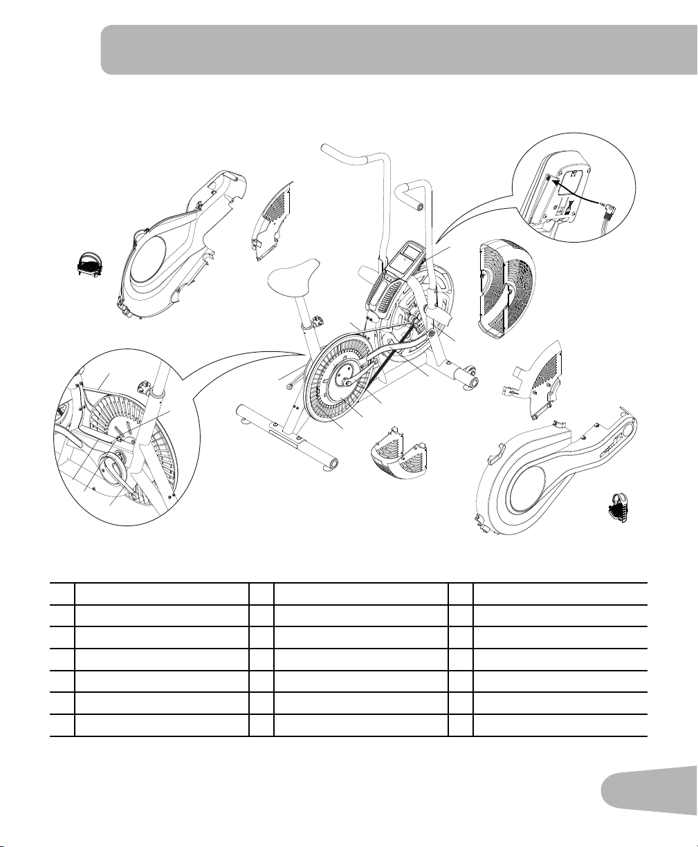
Maintenance Parts
A Console H Crank Arms O Speed Sensor Magnet
B Handlebars I Crank Covers P Data Cable
C Fan Assembly J Pedals Q RPM Sensor
D Fan Assembly Covers K Shroud, Right R Levelers
E Footpegs L Shroud, Left S Seat
F Arm Pivots M Drive Pulley T Seat Post
G Connector Arms N Drive Belt U AdjustmentKnob
F
I
A
I
P
P
B
C
D
D
D
D
E
G
L
K
J
J
H
H
U
T
S
R
R
R
N
M
P
N
M
O
Q
H
E
B
A
24
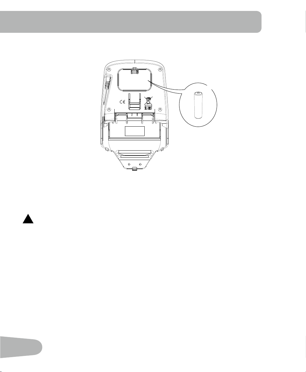
Replacing the Console Batteries
TheConsoledisplaywillshow“Batt”duringpowerupifthebatterylevelislow.When replacing
the batteries, make sure the batteries point in the +/– direction shown in the battery bay.
Note: The console uses AA size batteries (LR6).
!
Donotmixoldandnewbatteries.
Donotmixalkaline,standard(carbon-zinc),orrechargeable(Ni-Cd,Ni-MH,etc)batteries.
Be sure to remove the batteries to prevent corrosion damage if you are not going to use the
machineforanextendedperiodoftime.
+
-
X2
25
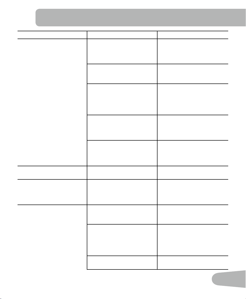
TROUBLESHOOTING
Condition/Problem Things to Check Solution
Console will not power up/turn
on/start
Batteries Make sure batteries are
installed correctly. If batteries
are correctly installed, replace
with a set of new batteries.
Check data cable integrity All wires in cable should be
intact. If any are visibly crimped
or cut, replace cable.
Check data cable connections/
orientation
Make sure cable is connected
securely and oriented properly.
Small latch on connector
should line up and snap into
place.
Check console display for
damage
Check for visual sign that
console display is cracked or
otherwise damaged. Replace
Console if damaged.
If the above steps do not
resolve the problem, contact
Customer Care for further
assistance.
Speed displayed is not
accurate
Display set to wrong unit of
measure. (English/Metric)
Change display units.
Speeddisplayedisalways“0”/
stuck in Pause mode
Data cable Make sure the data cable is
connected to the back of the
Console and the main frame
assembly.
No speed/RPM reading Check data cable integrity All wires in cable should be
intact. If any are cut or crimped,
replace cable.
Check data cable
connections/orientation
Be sure cable is connected
securely and oriented prop-
erly. Small latch on connector
should line up and snap into
place.
Check magnet position (re-
quiresshroudremoval)
Magnet should be in place on
pulley.
26
CheckRPMSensor(requires
shroud removal)
RPM sensor should be aligned
with magnet and connected
to data cable. Realign sensor
if necessary. Replace if there is
any damage to the sensor or
the connecting wire.
Console shuts off (enters sleep
mode) while in use
Check data cable integrity All wires in the cable should be
intact. If any are cut or crimped,
replace cable.
Check data cable
connections/orientation
Be sure cable is connected
securely and oriented prop-
erly. Small latch on connector
should line up and snap into
place.
Check magnet position (re-
quiresshroudremoval)
Magnet should be in place on
pulley.
Check RPM Sensor Contact Customer Care for
further assistance.
Unit rocks/does not sit level Check leveler adjustment Leveling feet may be turned in
or out to level bike.
Check surface under unit Adjustment may not be able
tocompensateforextremely
uneven surfaces. Move bike to
level area.
Pedals loose/unit difficult to
pedal
Check pedal to crank connec-
tion
Pedal should be tightened
securely to crank. Be sure con-
nection is not cross-threaded.
Checkcranktoaxleconnection Crank should be tightened
securelytoaxle.
Clicking sound when pedaling Check pedal to crank connec-
tion
Remove pedals and reattach
fully.
Seat post movement Check locking pin Be sure adjustment pin is
locked into one of the seat post
adjustment holes.
Check adjustment knob Be sure knob is securely tight-
ened.

27

Nautilus® Bowflex® Schwinn® Fitness Universal®
004-4565.111512.B