REV F DATE: 01/04/2024
USER MANUALS\21-29823_ELEVATE_USER MANUAL_BD3632IS (AUTON RET MERCH)_REF_SELF-SVC_BOX DOOR CASE
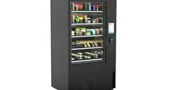
ELEVATE REFRIGERATED MODEL BD3632IS AUTONOMOUS RETAIL MERCHANDISER
> SELF-CONTAINED REFRIGERATION SYSTEM
> SEE LAST PAGE IN USER MANUAL FOR TRAINING ON SOFTWARE, SETUP, CALIBRATION,
CONFIGURATION, ONGOING MERCHANDISING, ADMIN FIRST TIME SETUP, ETC.
SCC P/N
21-29823
Elevate
READ AND SAVE THESE INSTRUCTIONS
USER
MANUAL
Structural Concepts Corp. ∙ 888 E. Porter Rd ∙ Muskegon, MI 49441 Phone: 231.798.8888 Fax: 231.798.4960 ∙ www.structuralconcepts.com
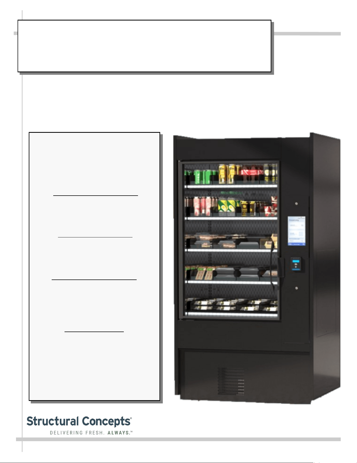
Important!
Overview of Structural Concepts
and Instant Retail Systems Unique
Collaboration on the Elevate
Autonomous Retail Merchandiser
Structural Concepts Model
BD3632IS includes autonomous
shopping technology from our
partner, Instant Retail Systems.
This manual includes instructions
for operating the equipment as
well as links for technology
onboarding and troubleshooting.
Contact Structural Concepts for
information pertaining to the
refrigerated display at:
Structural Concepts Corporation
1-800-433-9490 / Ext. 1
Contact Instant Retail Systems for
information pertaining to the
technology that powers the
autonomous shopping at:
Instant Retail Systems
1-615-236-6474
Support@InstantRS.com
2
TABLE OF CONTENTS
OVERVIEW / TYPE / COMPLIANCE / WARNINGS / PRECAUTIONS / WIRING / PLUGS …………...
INSTALLATION: CASE REMOVAL FROM SKID / SETUP / ACTIVATION ...…………………………..
ACTIVATION: Wi-Fi SETUP ……………………………………………………………………………….
GENERAL MERCHANDISER ILLUSTRATION - MODEL BD3632IS …...……………………………….
FRONT/REAR PANEL REMOVAL / CONNECTIONS CHECK / PREPARING CASE FOR
MERCHANDISING ………………………………………………………………………………...……
GENERAL OPERATION / WEIGHT SENSORS / SHELF LIGHT COLOR SCHEME …………………..
LOAD LEVEL GUIDE & TEMPERATURE GUIDE - MODEL BD3632IS ………………………………...
CLEANING SCHEDULE (TO BE PERFORMED BY STORE PERSONNEL) …..……………...…….….
PREVENTIVE MAINTENANCE - TO BE PERFORMED BY TRAINED SERVICE PROVIDERS ....…..
TROUBLESHOOTING (DEPENDING UPON TASK, TO BE PERFORMED BY EITHER TRAINED
SERVICE PROVIDERS OR GENERAL STORE PERSONNEL) ………………………………….
TROUBLESHOOTING - R-290 CONDENSING SYSTEM (BY TRAINED SERVICE PROVIDERS) .....
TROUBLESHOOTING - R-290 EVAPORATOR SYSTEM (BY TRAINED SERVICE PROVIDERS) ....
SERIAL LABEL LOCATION & INFORMATION LISTED / TECH INFO & SERVICE ……….…….……
PROGRAMMABLE CONTROLLER INFORMATION………………………………………..………….…..
INSTANT RETAIL SYSTEMS / STRUCTURAL CONCEPTS TECHNICAL SERVICE CONTACT
INFORMATION & LIMITED WARRANTY ……………………………………………………………...
3-4
5-7
8-9
10-13
14
15
16
17
18-19
20-23
24
25
26
27
28
3
OVERVIEW
• These Structural Concepts merchandisers are designed
to merchandise packaged products at 41 °F (5 °C) or
less product temperatures.
• Cases should be installed and operated according to this
operating manual’s instructions to ensure proper
performance. Improper use will void warranty.
• Component parts shall be replaced with like components.
NSF/ANSI TYPE II ENVIRONMENTAL CONDITIONS
• This unit is designed for the display of products in
ambient indoor store conditions where temperature and
humidity are maintained within a specific range.
•
NSF/ANSI Type II Conditions: Product is displayed in
store conditions with maximum ambient temperature of
80 °F (27 °C) and maximum relative humidity of 55%.
COMPLIANCE
• Performance issues when in violation of applicable NEC,
federal, state and local electrical and plumbing codes are not
covered by warranty. See below.
WARNINGS/DANGER
• This sheet contains important warnings to prevent injury or
death. Please read carefully!
REFRIGERANT DISCLOSURE STATEMENT
• This equipment is prohibited from use in California with any
refrigerants on the “List of Prohibited Substances” for that
specific end-use, in accordance with California Code of
Regulations, title 17, section 95374.
• This disclosure statement has been reviewed and approved
by Structural Concepts and Structural Concepts attests, under
penalty of perjury, that these statements are true & accurate.
WARNING: Hazardous moving parts. Do not operate unit with covers
removed. Fan blades may be exposed when deck panel is removed.
Disconnect power before removing deck panel.
WARNING
Risk of electric shock. Disconnect power before servicing unit.
CAUTION! More than one source of electrical supply is
employed with units that have separate circuits.
Disconnect ALL ELECTRICAL SOURCES before servicing.
WARNING
Condensate Pan is Hot!
Disconnect and allow to cool before cleaning or removing from case.
WARNING
ELECTRICAL
HAZARD
WARNING
KEEP
HANDS
CLEAR
HOT
SURFACE
WARNING
COMPLIANCE
This equipment MUST be installed in compliance with all applicable NEC,
federal, state and local electrical and plumbing codes.
OVERVIEW / TYPE / COMPLIANCE / WARNINGS / PRECAUTIONS / WIRING / PLUGS - PAGE 1 of 2
ATTENTION
CONTRACTORS
WARNING: This product can expose you to chemicals, including
Urethane (Ethyl Carbamate), which are known to the state of
California to cause cancer and birth defects or other reproductive
harm. For more information go to P65Warnings.ca.gov.
DANGER
Risk of fire or explosion. Flammable refrigerant is used in this case.
Consult repair manual/owner’s guide before servicing this product.
To minimize risk of possible ignition due to incorrect parts or improper service,
this case is ONLY to be serviced by factory authorized service personnel.
The flammable refrigerant type specified on case nameplate is on serial label.
This case’s R290 refrigerant lower flammability limit (LFL) is .038 (114kg/m³).
4
PRECAUTIONS
• This sheet contains important precautions to prevent
damage to unit or merchandise. Please read carefully!
• See previous page for specifics on OVERVIEW, TYPE,
COMPLIANCE and WARNINGS.
OVERVIEW / TYPE / COMPLIANCE / WARNINGS / PRECAUTIONS / WIRING / PLUGS - PAGE 2 of 2
WIRING DIAGRAM FORMAT & LOCATION
• Each case has its own wiring diagram folded and in its own
packet.
• Wiring diagram may be near ballast box, field wiring box,
raceway cover, or other related location.
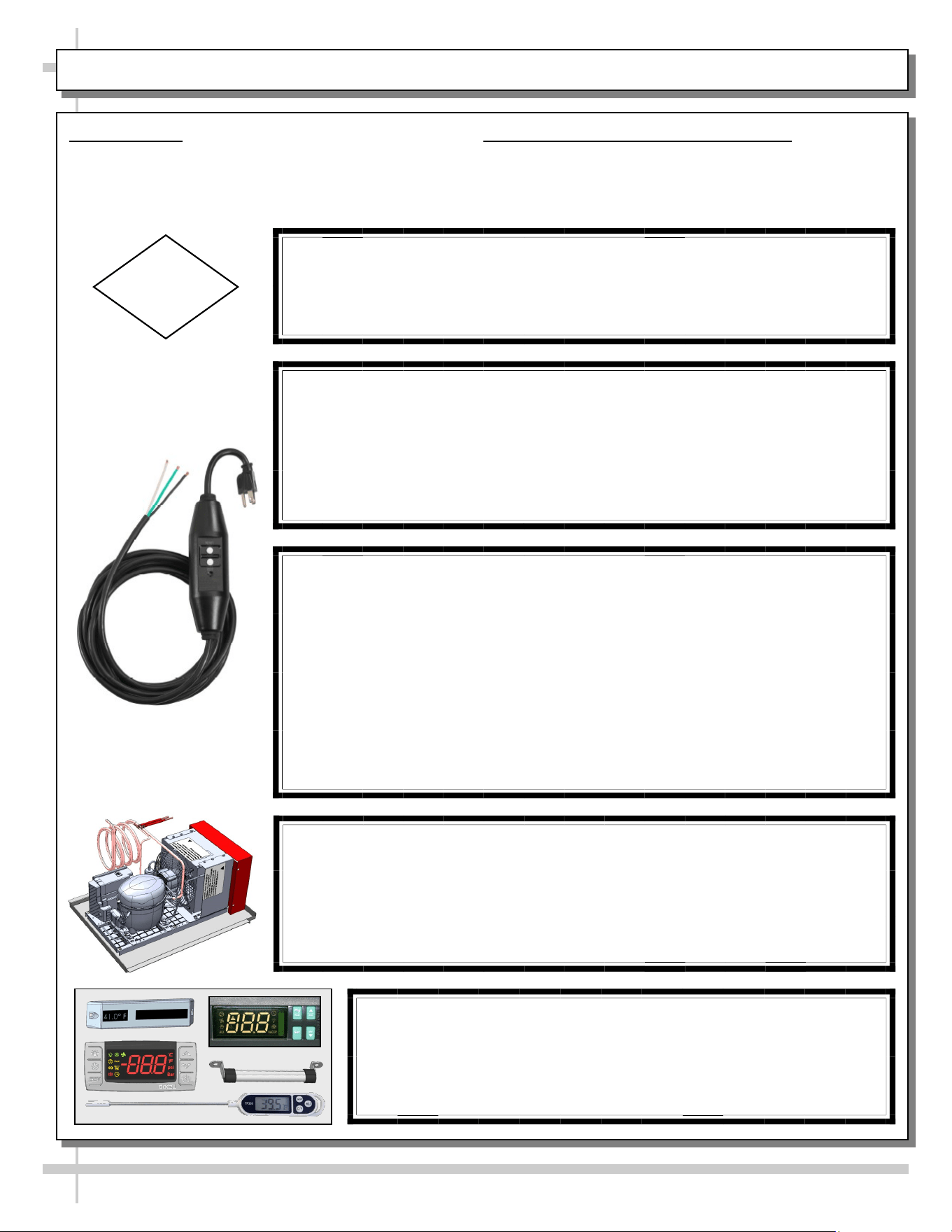
TOWER’S 15 FT. IN-LINE GFCI WITH FLYING 14/3 LEADS
• 14/3 AWG SJTW cord
• Trip level 4-6 Ma. Trip response time less than 25mS
• UL listed & UL listed to Canadian Safety Standards
• Automatic reset
• UL rainproof rated for outdoor use
• Rated for 125 volt, 15 amp use
• Open neutral and grounded neutral protection
• Operating temperature range -31 degree F to 150.8 degree F
• Impact resistant case
CAUTION! LAMP REPLACEMENT GUIDELINES
LED lamps reflect specific size, shape and design.
Any replacements must meet factory specifications, resist breakage
and reflect similar appearance as lamps from factory.
CAUTION
CAUTION! POWER CORD AND PLUG MAINTENANCE
This vending case has ONE (1) GFCI In-line 120V power cord with Auto
Reset. Power cord must be unplugged during case movement, testing or
repairs.
--- --- --- --- --- --- --- --- --- --- --- --- --- --- --- --- --- --- --- --- ---
Risk of electric shock. If cord or in-line GFCI becomes damaged, replace
only with cord and GFCI of same type.
CAUTION! CHECK CONDENSATE PAN, POSITION & CONNECTIONS!
Water on flooring can cause extensive damage!
• Before powering up case, check that condensate pan is positioned directly
under case’s condensate drain.
• Also, check that there are NO LOOSE CONNECTIONS, including overflow
condensate pan and its power cord plug (if part of the condensate package).
CAUTION! DO NOT RELY ON THERMOMETERS OR
THERMOSTATS FOR PRODUCT (FOOD) TEMPERATURES.
• Thermometers & thermostats reflect air temperatures ONLY.
• For ACTUAL product (food) temperatures, use a calibrated food
probe thermometers ONLY.
• For accurate readings, DO NOT use infrared food thermometers.
5
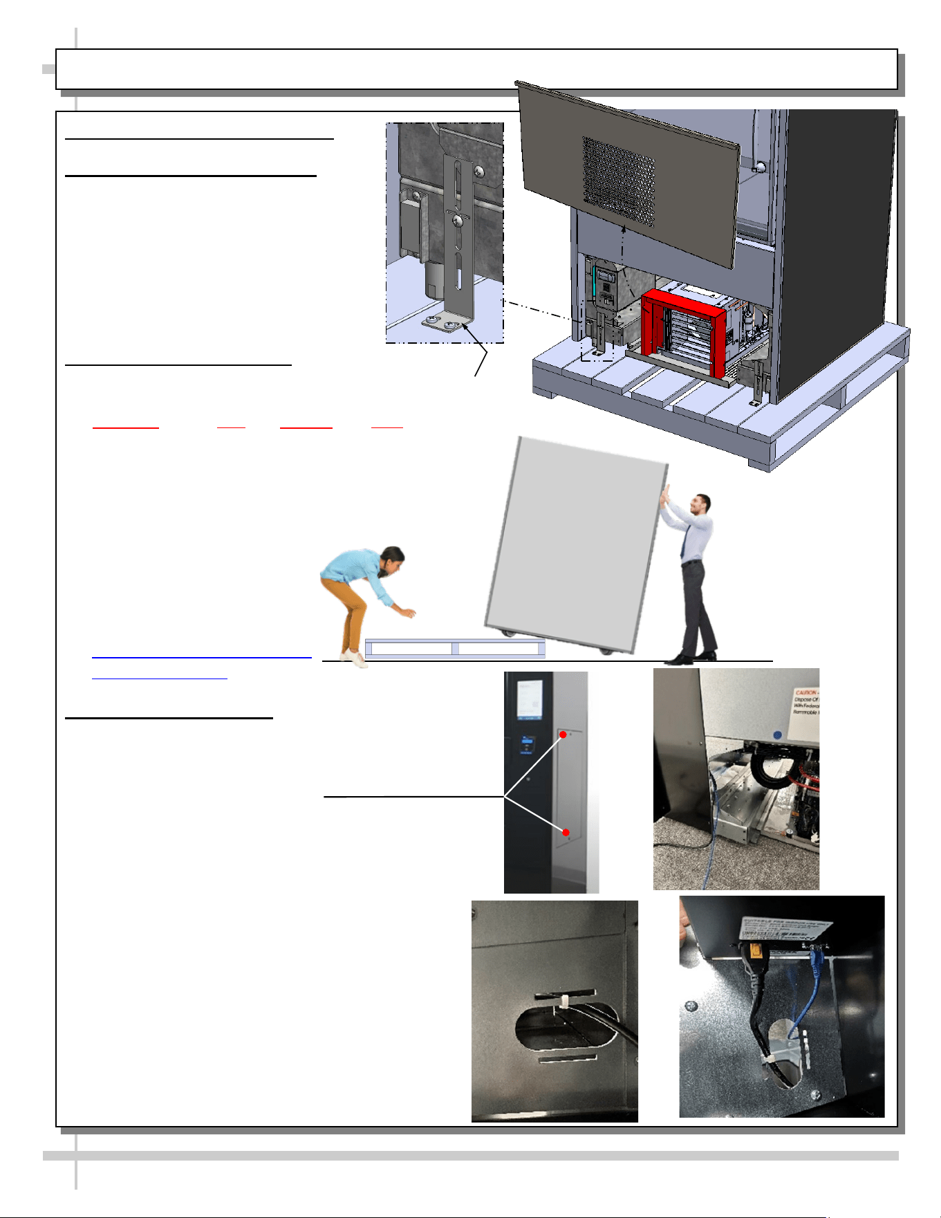
1. Remove Front and Rear Panel
2. Disconnect Case From Skid
a. Remove shipping brackets that secure
casters to skid
b. Important! Case is shipped with levelers
in the DOWN position (for stability). To
prevent damage to case, all levelers must
be raised ALL THE WAY UP before
moving unit off skid and into position.
3. Remove Case From Skid
a. Important! No less than three (3) people are
required to remove case from skid. Remember,
ALWAYS lift your legs and NEVER your back
to avoid serious injury.
b. After levelers are raised, walk/slide case to edge of
skid.
c. Gently ease front edge of case off the skid and onto
the floor.
d. Tilt case forward and have an
assistant remove skid from under
case.
e. Ease back side of the case to the
floor.
Uncrating Best Practices Video |
Structural Concepts
4. Plug in Ethernet Cable
a. Slide case to the final position but leave room
behind case
b. Remove side panel (right side of case) by removing
the two (2) 6-point hex screws [A]
c. Plug Ethernet cable into wall jack.
d. With back panel still off, follow the Black power
cable on the left side (facing back of the case) to
find opening in bottom of shroud [B].
e. Feed Ethernet Cable through the opening [C].
f. Locate Ethernet Port to the right of the power cord
and plug in cable [D].
g. Replace Side & Rear Panel
INSTALLATION: CASE REMOVAL FROM SKID / SETUP / ACTIVATION - PAGE 1 of 3
Shipping
Bracket (Typ.)
Front
Panel
A
B
C
D
6
5. Position & Align Case
a. Before adjusting levelers, make certain that the case is in proper position and, if required, aligned with adjoining
case(s).
b. This may require the repositioning of the case you are installing or the already
positioned case(s).
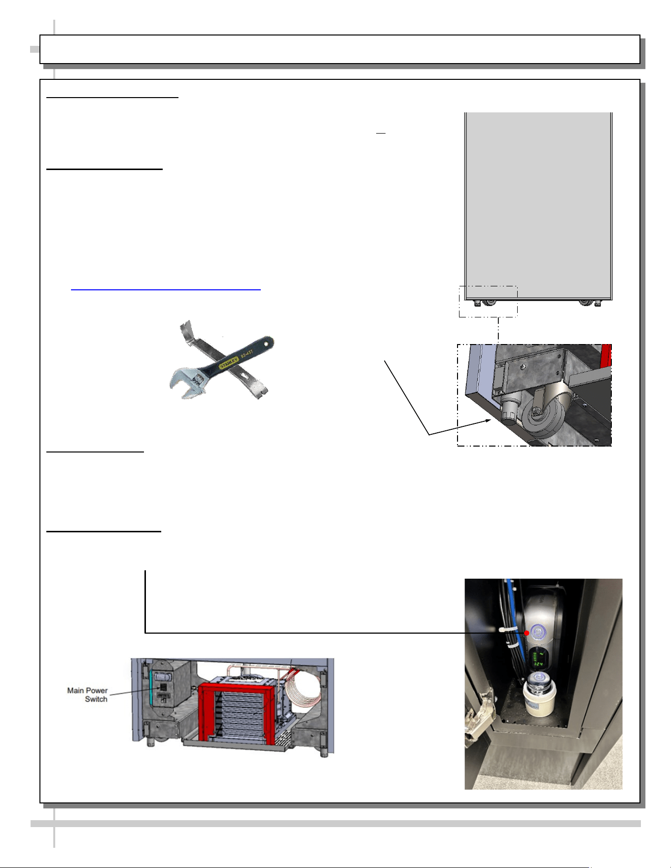
6. Adjusting Levelers
a. Important! After case is in proper position, levelers must then be LOWERED to
floor.
b. Adjust levelers so the case is level and plumb. Depending upon case weight, it
may be necessary to use a pry bar to do so.
c. Use adjustable wrench to adjust leveler.
d. DO NOT use pry bar on end panel as it may chip
e. Use pry bar ONLY on base frame to avoid damaging case.
f. See Illustration to the right.
g. Click link for reference video.
ARM Initial Setup | Structural Concepts
7. Opening E-Box
a. Locate small manilla envelope containing two (2) keys taped to front door.
b. Insert keys into the two (2) locks, above and below the touchscreen, and turn so flat part
of keys are parallel with ground.
c. E-Box door is held shut with magnets, it will take a bit of force to get the door open.
8. Powering On Case
a. Locate Main Power Switch on the Front Lower Left side of the Case and press on to start
refrigeration compressor [E].
b. Press and hold Power Button inside the E-Box to power on UPS [F].
Pry Bar
Adjustable
Wrench
Leveler
(Typical)
INSTALLATION: CASE REMOVAL FROM SKID / SETUP / ACTIVATION - PAGE 2 of 3
E
F
7
9. Replace Front Panel
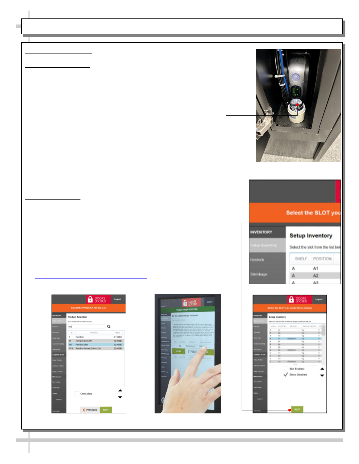
10. Calibrating Shelves
a. Tap top left corner of touchscreen rapidly (at least 5x) to bring up admin log-in.
b. Enter log-in information received from Instant Retail Systems.
c. Press Red “Door Locked” Button at top of screen to unlock door.
d. Open the now unlocked door.
e. Find Planograms in the Menu Bar on the left side and select “SCC ARM Planogram”.
f. Load Planogram
g. Locate test weight in front of the UPS in the E-Box [G] and unscrew top.
h. Find “Calibrate Shelves” in the Menu Bar on the left side of the screen.
i. Select shelf; click “Next”
j. Set test weight (1000 grams); click “Next”
k. Place test weight in first bin on selected shelf.
l. Once screen reads “Stable”; click “Calibrate”.
m. Repeat steps k & l for rest of shelves.
n. Repeat steps i - m for rest of shelves.
o. Click link for reference video
ARM Shelf Calibration | Structural Concepts
11. Inventory Setup
a. Once the shelves have been calibrated, select “Setup Inventory” [H] in the Menu
Bar on the left side of the screen.
b. Pick shelf and Position in which you would like to set up inventory; click “Next” [I].
c. Search for product in Product Inventory; click “Next” [J].
d. Place one (1) product on shelf and wait for screen to read “Stable”;
click “Add” [K].
e. Repeat step d above two (2) more times to verify correct weight of product;
click “Finish”.
f. Repeat steps b - e above for the rest of the bins.
g. Click link for reference video
ARM Inventory Setup | Structural Concepts
INSTALLATION: CASE REMOVAL FROM SKID / SETUP / ACTIVATION - PAGE 3 of 3
H
I
J
K
8
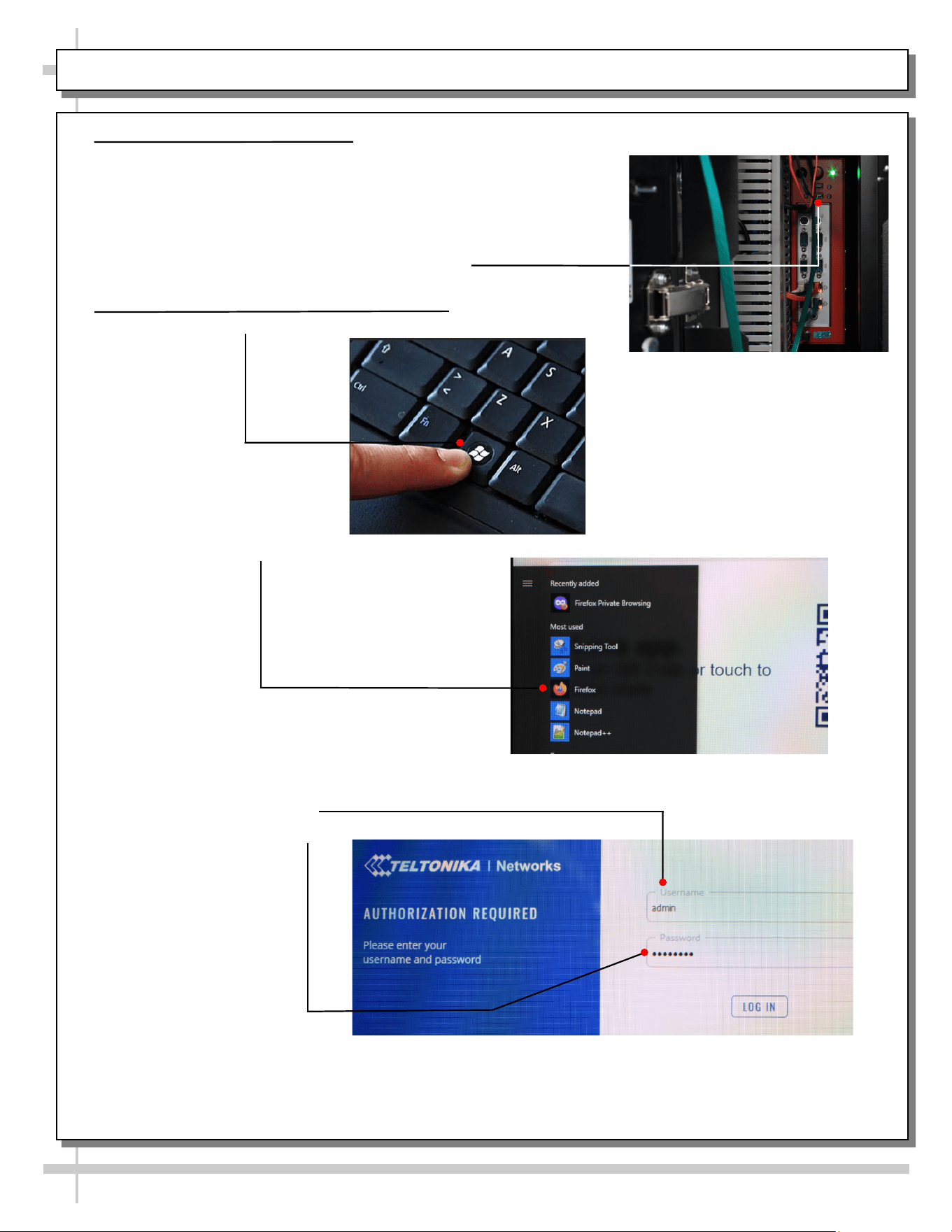
1. Connecting Keyboard to PC
a. Locate keys
b. Turn key in top lock 90° so key is parallel with ground and turn key in
bottom lock 180°.
c. E-Box door is held shut with magnets, it will take a bit of force to get
the door open.
d. Find Red PC above the UPS
e. Plug-in keyboard to one of the open USB ports.
2. Logging into Router Administration Site
a. Press the “Windows” key to display Start Menu
b. Select Mozilla Firefox browser
c. In the address bar, type 192.168.60.1 to navigate to the router log-in
d. The default log-in information in below:
User Name: admin
Password: admin01
e. On the first login, you’ll be prompted to enter a new password. Set it to
“Admin01!”
Activation: Wi-Fi Setup - PAGE 1 of 2
9
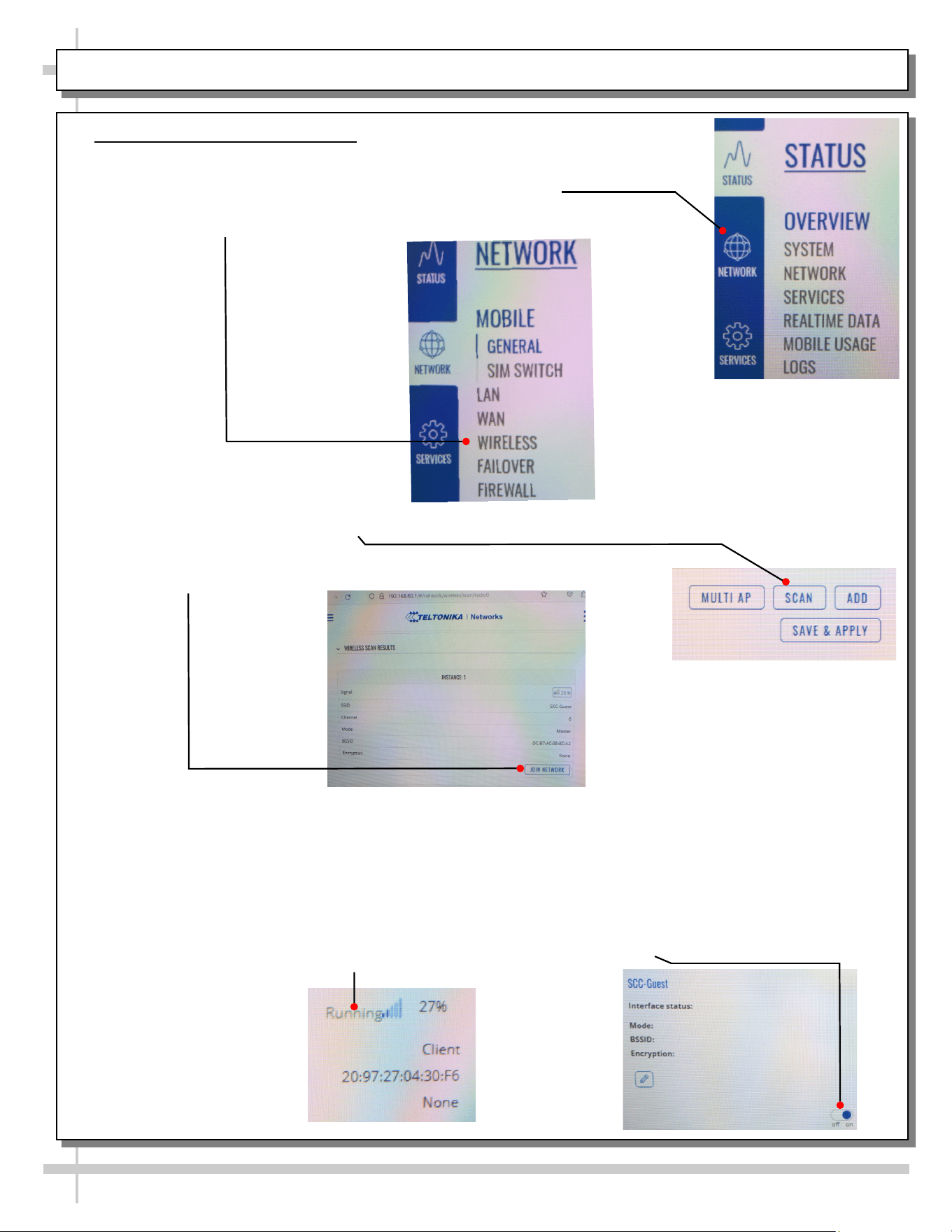
3. Connecting to Wi-Fi Network
a. Once you are logged into the Taltonika interface, press the 3 Bar menu in the top
left corner.
b. Select the “Network” option down the left side of the screen.
c. Press the 3 Bar menu again
d. Select “Wireless” in the white select menu.
e. On the right side, press the “Scan” button to search for surrounding wireless
networks.
f. Find desired Network from the resulting list the scan produces and press
“Join Network”
g. You will be redirected to a window where you will be asked to Name the new
network, set the name of the new network to “wifi1”
h. Press the “Submit” button
i. You will again be redirected to another window where you are asked to enter the
desired Wi-Fi password.
j. The next window that opens will be Interface Configuration. Values here, mostly,
should be left unchanged to avoid connection problems, because they are
dictated by Access Point.
k. Verify that the switch at the bottom of desired network window is turned “On” and
the Interface Status says “Running”.
Activation: Wi-Fi Setup - PAGE 2 of 2
10
GENERAL MERCHANDISER ILLUSTRATION - MODEL BD3632IS - PAGE 1 of 4
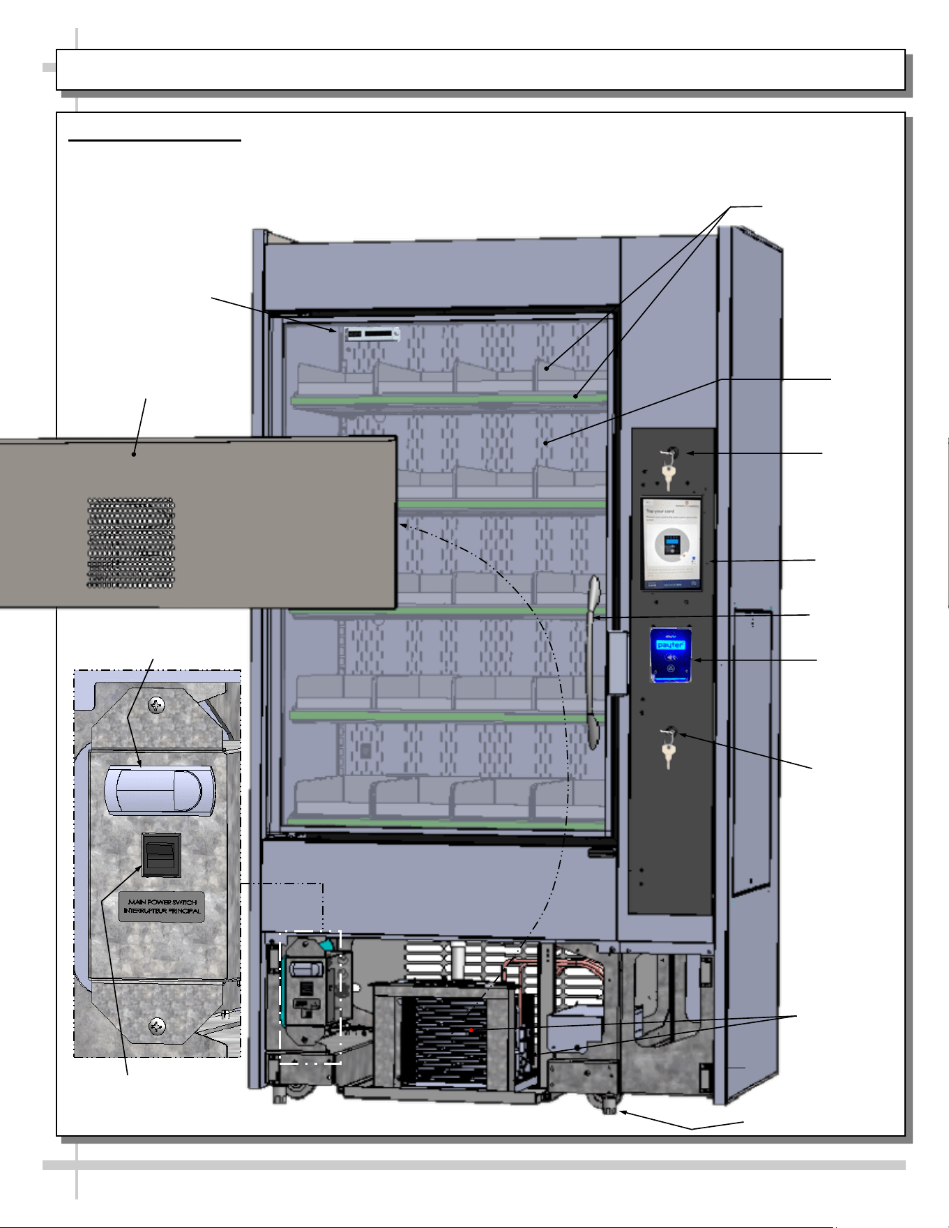
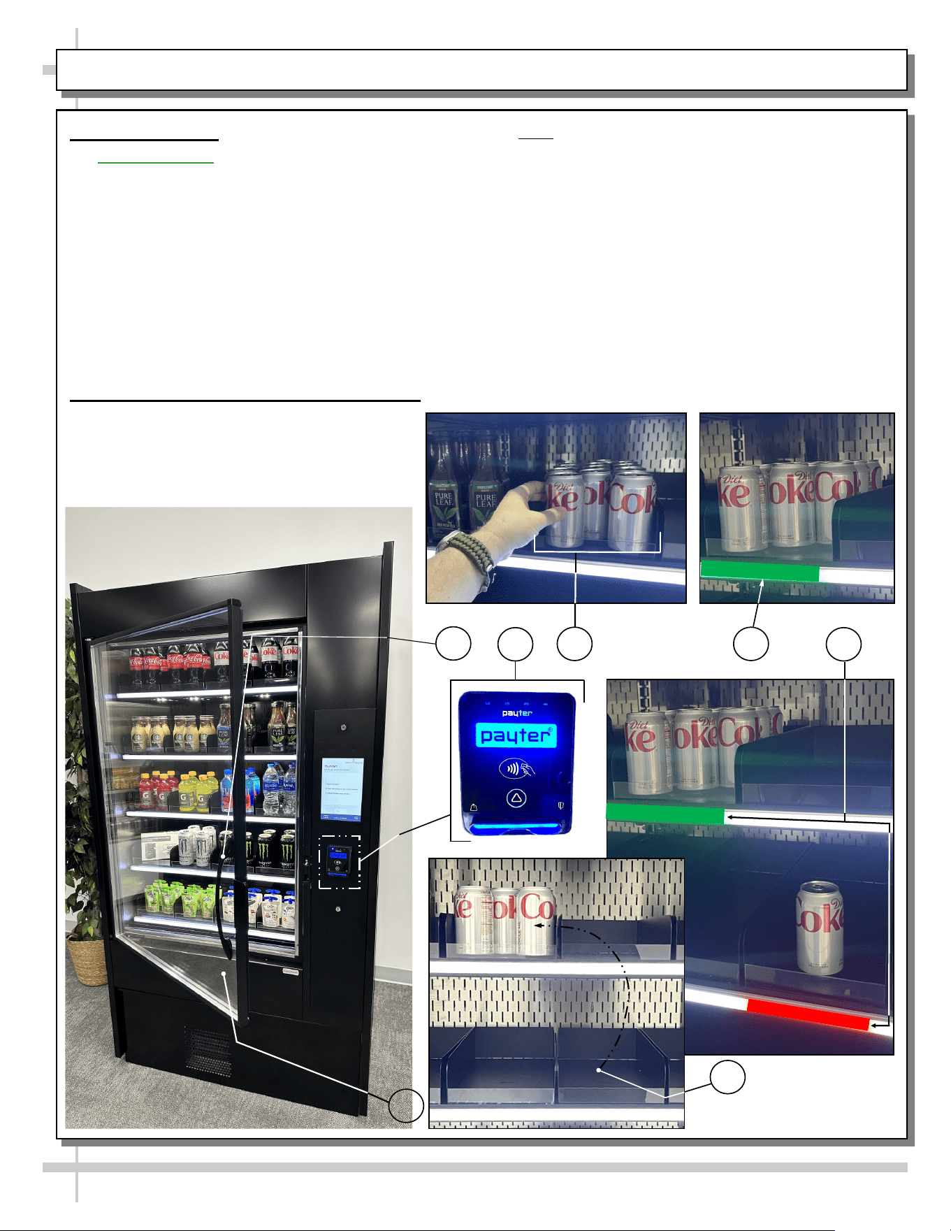
1. Front View of Case
• View is shown with front panel removed (for
electrical box & condenser package viewing).
• Vending controls system (monitor, payment
processor, locks, etc.) is at right side of case.
• Shelves/dividers have weight
sensors for product weighing
and pricing.
Lock/Key
Lock/Key
Payment
Processor
Condenser
Package
Programmable
Controller
Main Power
Switch
Door
Handle
Front Panel
Shown Removed
Shelves / Dividers
(For Separate
Product Weighing
and Pricing)
Rear
Plenum
Leveler (Typ.)
Vending
Monitor
Thermometer
11
GENERAL MERCHANDISER ILLUSTRATION - MODEL BD3632IS - PAGE 2 of 4
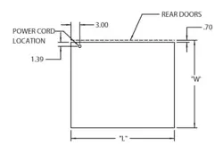
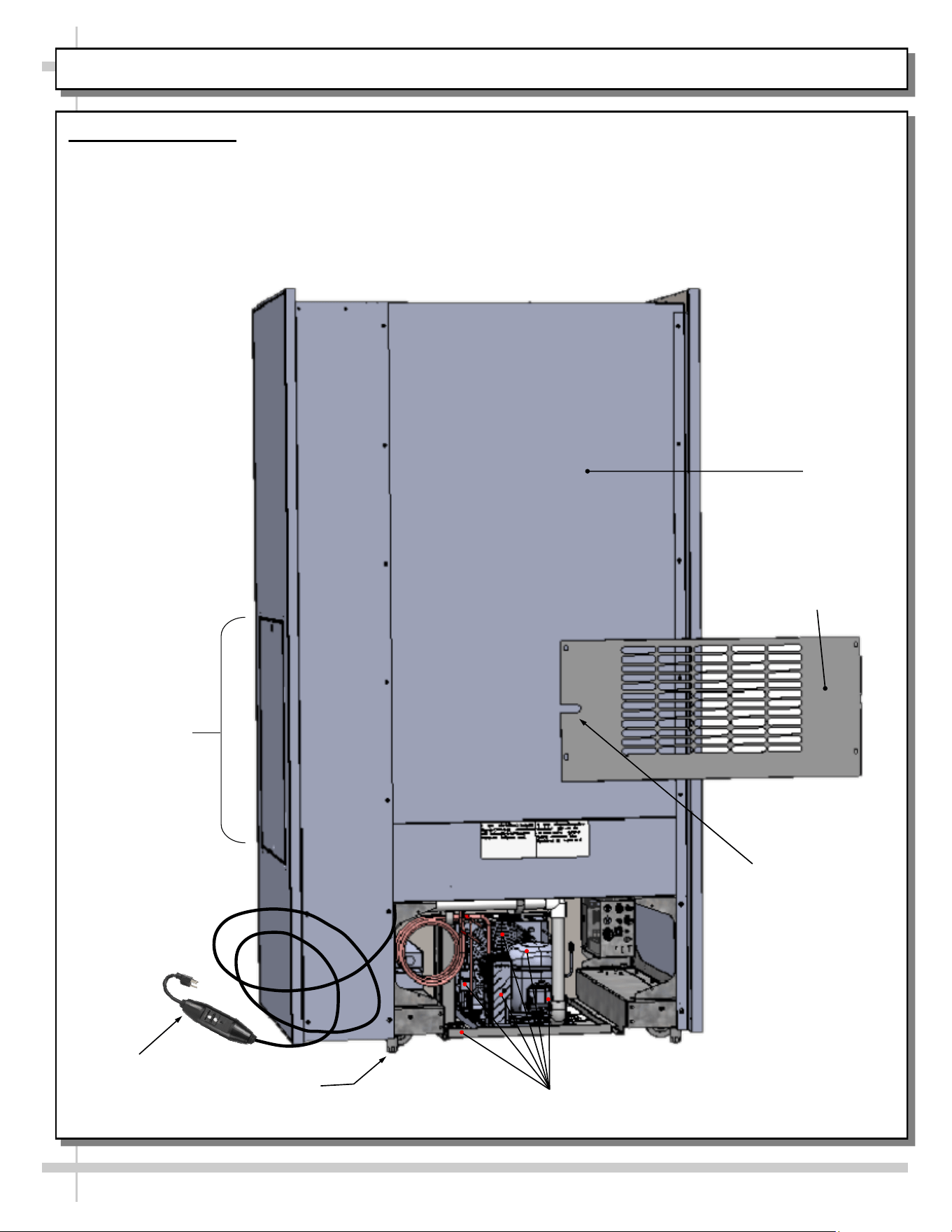
2. Rear View of Case
• Rear panel is shown removed to show access to condenser package and electrical box.
• Vending Control System is at rear-left of case.
Power
Cord With In-line
GFCI Plug
Power Cord Slot
Rear Panel
Rear Panel
Shown Removed
Condenser Package
Leveler (Typ.)
Side Panel
12
GENERAL MERCHANDISER ILLUSTRATION - MODEL BD3632IS - PAGE 3 of 4
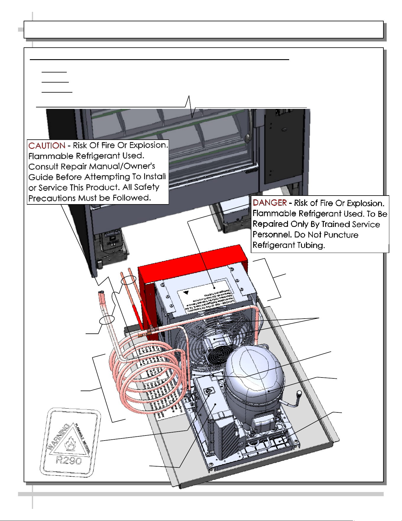
3. Self-Contained Hot Gas Loop Condensate Package (Shown Rotated 180°)
• Caution: Only trained service providers are to provide maintenance and service to unit.
• Warning! Disconnect power before providing maintenance and service to unit.
• Important: Carefully read all Warning/Caution/Danger labels on unit!
Compressor
Filter Dryer
Compressor
Inverter
Condenser Fan
& Housing
Courtesy Loop
Condenser Coil
Housing
Hot Gas Loop
Condensate
Pan
Refrigeration
Lines
13
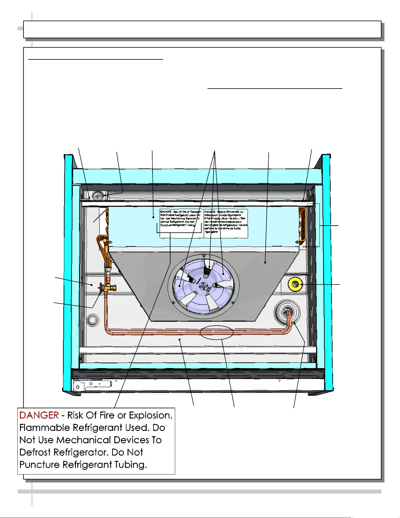
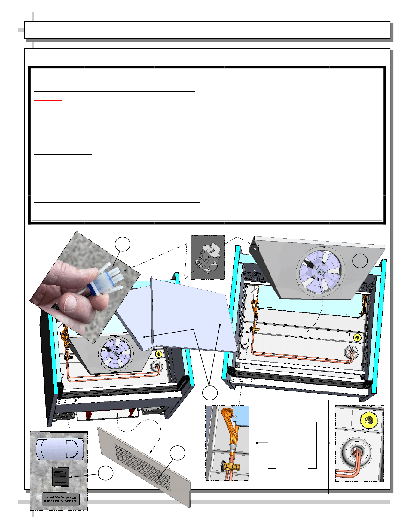
GENERAL MERCHANDISER ILLUSTRATION - MODEL BD3632IS - PAGE 4 of 4
5. Evaporator Coil Fans / Air Discharge
When case is energized, refrigeration will be provided.
• Evaporator coil fan should turn on.
• From inside of the case, check for discharge air
from honeycomb discharge duct to confirm that
the fan is functioning properly.
Drain
Wire
Route
Trough
Refrigeration
Line Route
Refrigeration
Lines
TXV
Evaporator Fan
& Blades
Evaporator
Fan Shroud
• When the case is in a start-up mode or has been
idle for a long period of time, the unit will require
75-minutes of run time to pull-down temperature.
6. TXV (Thermostatic Expansion Valve)
• TXV (at customer-left side of case).
• Decking must be removed for access.
• See illustration below for TXV location.
Close-Off
Coil
Cover
Tub
Close-Off
Evaporator
Coil
14
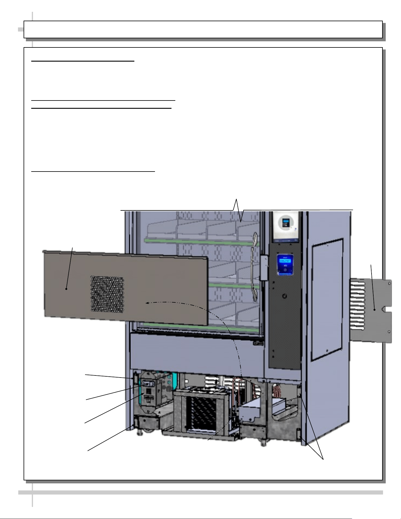
FRONT/REAR PANEL REMOVAL / CONNECTIONS CHECK / PREPARING CASE FOR MERCHANDISING
1. Removable Front/Rear Panel
• Front and rear panel can be removed/replaced by
either freeing from magnets or screw removal (as
illustrated below).
2. Check Condenser Package Connections
Before Preparing Case For Merchandising
• Caution! Connections can come loose during
shipment; this can allow water to overflow
onto floor, causing damage!
• When case in is proper location, remove front
and rear panels to check for loose connections,
including overflow condensate pan and plug.
3. Preparing Case For Merchandising
• Caution! Do not attempt to prep case for
merchandising without following Instant
Retail System’s step-by-step instructions!
> Access the QR Code found on the last page this
User Manual. Instant Retail System’s video
presentations will instruct you how to do the following:
> Access keys at case rear.
> Unlock main controller door & remove cables.
> Remove thumb screws, side panel, cables and
envelope (if present).
> Confirm that sim card is in modem by using pin key.
> Release latch to open main door.
> Remove packaging material from shelves along with
cooler manual and leveler adjustment tool.
> Align and connect additional cases to main case.
> Turn on main power supply/battery backup. The
modem, routers, computers, payment terminal and
kiosk screen will energize.
> Energize additional units (if any).
> Level system (so main door will latch properly).
> Install braces (if required).
Magnet
Front Panel
Main Power
Switch
Magnet
Magnets
Programmable
Controller
Rear
Panel
2
General Operation
• Important Note: Software activation through
Instant Retail Systems is required before this
merchandiser can be fully operational. See last
page of this User Manual for instructions on
contacting Instant Retail Systems.
• Each shelf consists of four (4) bins that are screwed
onto their respective shelves.
• Each shelf has a color-coded light bar (at front)
which lights up when case is operational.
• DO NOT separate shelving components.
• See TROUBLESHOOTING (TO BE PERFORMED
BY TRAINED SERVICE PROVIDER ONLY)
section in manual if there is a shelving malfunction.
Weight Sensors / Shelf Light Color Scheme
Follow these steps to operate merchandiser.
1. Submit payment.
2. Open by grasping handle and slowly
opening door.
3. Select product.
15
GENERAL OPERATION / WEIGHT SENSORS / SHELF LIGHT COLOR SCHEME
4. Note: the light at front of shelf (that had product on
it) will now turn green. This signifies that product(s)
is added to your cart.
5. If product is inadvertently placed in the wrong bin,
the weight sensors detect an error and the shelf light
(in front of that particular bin) will turn red (signifying
an error). Note that the green light is STILL on in the
bin where the product supply was provided
(signifying that the transaction is still in the process
of being processed).
6. Product MUST be either A) placed back onto correct
shelf or B) removed from the bin (and purchased) for
the red light to be turned back to white.
7. After desired product has been removed from the
bin, the door may be shut, completing the sale.
1
3 4
5
7
6
16
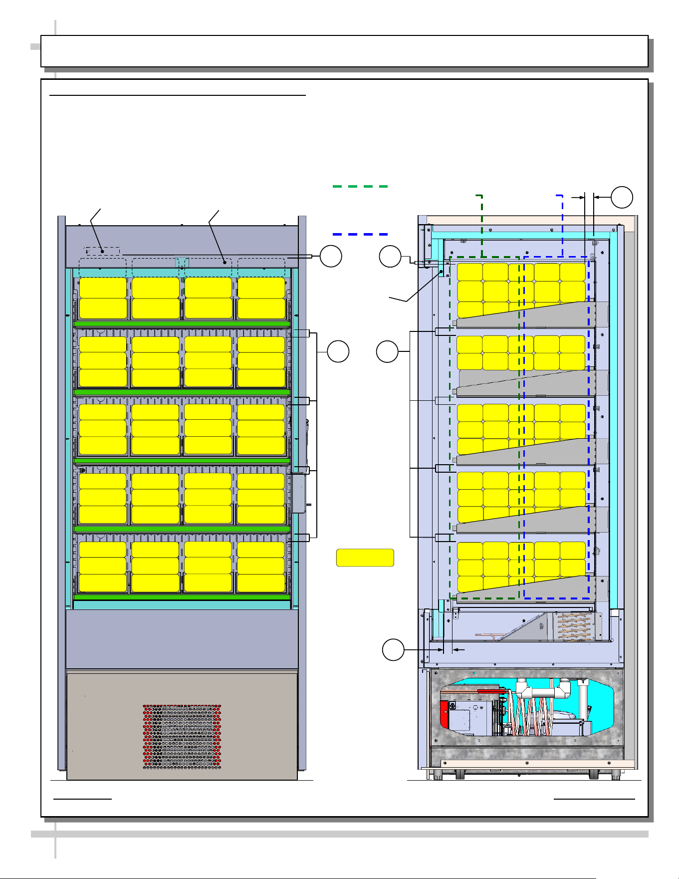
LOAD LEVEL GUIDE & TEMPERATURE GUIDE - MODEL BD3632IS
LOAD LEVEL & TEMPERATURE GUIDE - MODEL BD3632IS
>> FOLLOW THESE PRODUCT PLACEMENT GUIDELINES TO
MAINTAIN DESIRED PRODUCT TEMPERATURES.
>> FRONT TO REAR PRODUCT TEMPS ARE ESTIMATES ONLY.
>> NOTES CORRESPOND WITH ILLUSTRATIONS SHOWN.
1. AT TOP SHELF, KEEP PRODUCT BELOW THERMOMETER
(THAT IS ATTACHED TO REAR PERFORATED PLENUM).
2. ALLOW AT LEAST 1” SPACE BETWEEN PRODUCT AND ITS
SHELF ABOVE.
3. AT CASE REAR, ALLOW AT LEAST 1” SPACE BETWEEN
PRODUCT AND REAR PERFORATED PLENUM.
4. DO NOT BLOCK 1 1/4” AIR RETURN OPENING WITH PRODUCT.
>> IF YOU ARE UNABLE TO MAINTAIN DESIRED PRODUCT
TEMPERATURES, SEE TROUBLESHOOTING SECTION IN MANUAL.
37 °F TO 41 °F
PRODUCT AT
CASE FRONT
33 °F To 37 °F
PRODUCT AT
CASE REAR
THERMOMETER
MODEL BD3632IS SHOWN ABOVE. CASE IS PARTIALLY DISASSEMBLED,
CROSS-SECTIONED AND PACKAGED PRODUCT LADEN FOR ILLUSTRATIVE PURPOSES
PRODUCT BEHIND HEADER
SHOWN WITH HIDDEN LINES (TYP.)
HEADER
PACKAGED
PRODUCT
ILLUSTRATION
PRODUCT
TEMPERATURE
RANGE SHOWN
AT RIGHT.
2
1
2
1
3
4
17
CLEANING SCHEDULE - PERFORMED BY STORE PERSONNEL
FREQ. INSTRUCTIONS
Daily Inner Metal Components: Shelves, Decks, Rear Perforated Plenum, Inner End Panels, Etc.):
• Wipe with cloth dipped in mild-soapy water. Dry with soft cloth.
Daily Outer Metal Components: Door Frame, Door Handles, Lower Panels, End Panels, Etc.):
• Wipe with cloth dipped in mild-soapy water. Dry with soft cloth.
Monthly Glass Surface (Door):
• Clean inside and out with household or commercial glass cleaner. Dry with soft cloth or paper towel.
18
WARNING! TURN OFF CASE BEFORE PERFORMING PREVENTIVE MAINTENANCE!
QUARTERLY PREVENTIVE MAINTENANCE INSTRUCTIONS
Tub, Coil, Drain, Fan Blades, Motors, Brackets:
Caution! Do Not Clean or Perform Service On Unit While It Is Energized!
1. Remove front panel (to access controls). No screw removal is required. Place in safe place away from
foot traffic.
2. Turn off main power switch (located near programmable thermostat).
3. Remove deck pans. Place in safe place away from foot traffic.
4. Disconnect power cord that energized fan panel.
5. Grasp fan shroud assembly. Lift up and away from case. Place in safe place away from foot traffic.
Cleaning Process:
• Use vacuum to remove excessive residue AND to remove dust in coil.
• Use clean cloth and/or nylon brush with warm water and mild soap solution to clean tub, drain, trough,
TXV, lines, solenoid, coil & coil tubes. See enlarged view of components to be cleaned (lower-right).
• Remove debris that may clog drain.
• Wipe down fan blades, motors and brackets with moist cloth. Dry components with paper towel.
Returning Components / Restoring Power To Case:
• Replace/reconnect components in reverse order they were removed or disconnected.
• Turn main power switch back on. Check that fans are operational.
PREVENTIVE MAINTENANCE - TO BE PERFORMED BY TRAINED SERVICE PROVIDERS ONLY - 1 of 2
3
2
1
Enlarged
View Of
Components
To Be
Cleaned
4
5
19
WARNING! TURN OFF CASE BEFORE PERFORMING PREVENTIVE MAINTENANCE!
QUARTERLY PREVENTIVE MAINTENANCE INSTRUCTIONS, CONT’D
Under Case Cleaning:
Whenever refrigeration assembly is removed from underside of case, vacuum (or broom) under case to
remove all dust, debris and dirt that may collect.
Condensate Package:
Caution! You must turn main power switch off before cleaning!
• Remove front panel. Turn main power switch off and allow components to cool.
• Carefully and slowly slide condensate package out from under case.
• Use a soft-bristled scrub-brush and non-corrosive de-scaling solution (to remove calcium, lime and
rust) from condensate pan. Wipe down courtesy loop. Follow de-scaling solution’s instructions as to
proper dilution and safety precautions.
• After thoroughly cleaning pan with brush and solution, rinse thoroughly with clean water
(in spray bottle) and wipe dry with sponge or paper towel.
• Use moist cloth to wipe off dust & debris that collects on various parts (hot gas loop condensate pan,
compressor fan, blades and housing, fans, sight glass (if any), refrigeration lines, courtesy loop,
overflow pan (if any), etc.
• Slide condensate package back under case.
• Return front panel to case.
• See GENERAL MERCHANDISER ILLUSTRATION - MODEL BD3632IS - PAGE 3 of 4 in this
operating manual for condensate package illustration.
PREVENTIVE MAINTENANCE - TO BE PERFORMED BY TRAINED SERVICE PROVIDERS ONLY - 2 of 2
20
CONDITION TROUBLESHOOTING
Case Not
Lining Up
See INSTALLATION section in this manual for instructions on properly aligning case
(alongside other cases) and adjusting levelers.
Water Is On
The Floor
Caution! Water on flooring can cause much damage! Until cause is determined (and
repaired), follow these procedures:
• Use wet-dry vacuum (or mop & bucket) to remove standing water.
• Use ‘catch pans’ for water to drain into. Swap out regularly until case has completely
drained.
Check that the drain trap is free from debris.
Check that the drain hose/pipe is correctly positioned over condensate pan (or floor drain,
for remote units).
Check store conditions.
• To prevent condensation in NSF/ANSI Type II environments, maximum conditions are
to be 55% relative humidity / 80° Fahrenheit.
Check that condensate pan components have no loose connections.
Check that overflow condensate pan (if any) has its power cord plug properly plugged into
electrical box.
Check that overflow condensate pan (if any) is not malfunctioning. Its electric rod heater
should be heating up when case is energized.
Caution! Disruption of power can cause water to overflow pan and seep onto flooring
causing damage! Check that power to case is constant. Until power is restored, follow
these procedures:
• Use wet-dry vacuum (or mop & bucket) to remove standing water.
• Use ‘catch pans’ for water to drainage. Swap out regularly until drainage of case is
complete (or until power is restored).
• When power to case is restored, condensate pan should function properly and water
will no longer overflow onto flooring.
TROUBLESHOOTING (TO BE PERFORMED BY TRAINED SERVICE PROVIDER ONLY) - PAGE 1 of 4
21
CONDITION TROUBLESHOOTING
Fan Emits Excessive
Noise
Check that the case is aligned, level and plumb.
Check evaporator fan for cleanliness.
Unplug/power off fan motor. Check motor shaft for bearing wear.
Check that fan motor is securely mounted in brackets.
Verify that fan blades are securely mounted to fan motor.
Check that nothing is preventing blade rotation.
Check that the fan shroud is properly secured.
Fan Is Not Working Check that the MAIN power switch is on.
Check that fan connector is securely plugged in at fan shroud.
Check that fan connector is securely plugged in near close-off.
Check for foreign material obstructing fan performance.
Check that fan blade freely rotates within fan shrouds
Check that power is going to fans
Check that fan wiring is connected on terminal blocks.
Programmable
Controller Display
Is Blank
Check that the MAIN power switch is on.
Check circuit breaker box for tripped circuits.
Programmable
Controller Display Is
Flashing
See your case’s serial label for your model’s specified settings. See SERIAL
LABEL LOCATION & INFORMATION LISTED / TECH INFO & SERVICE for
label location, etc.
System Not Operating Check that the utility power is on.
Check that the MAIN power switch is on.
Check the circuit breaker box for tripped circuits.
LED Light Is Not
Working
Check that light switch is in the on position.
Check that the light cord and plug is properly connected. See LED LIGHT
FIXTURE IN HEADER section in this manual for specifics.
Service Technicians Only: Check voltage at LED drivers. If voltage is entering
but not exiting, LED driver may be faulty.
TROUBLESHOOTING (TO BE PERFORMED BY TRAINED SERVICE PROVIDER ONLY) - PAGE 2 of 4
22
CONDITION TROUBLESHOOTING
Weight Sensors On
Shelf/Shelves Are
Malfunctioning
Contact Instant Retail Systems (see last page of User Manual).
Color-Coded Lights
On Shelf/Shelves
Are Malfunctioning
Contact Instant Retail Systems (see last page of User Manual).
Screen/Monitor Is
Malfunctioning
Contact Instant Retail Systems (see last page of User Manual).
Payment Processor
Is Malfunctioning
Contact Instant Retail Systems (see last page of User Manual).
Case Is Not Holding
Temperature
You must load case with pre-chilled product. A warm load can result in air
temperature of food storage compartment exceeding 45 °F (7 °C) for more than
15 minutes; this can result in vending mechanism disablement.
Temperature changes during defrost mode but will return to normal.
Check that case is not directly in the sun.
Check that condenser coil has been cleaned.
Check air return opening for obstructions.
If sight glass is part of condensing unit, check if it is flashing or showing low
charge.
Check set point temperature; it may be adjusted too high.
Condensing Unit Is
Not Operating
Check that the power is turned on.
Check if programmable controller settings are properly set. See your case’s serial
label for your model’s specified settings. See SERIAL LABEL LOCATION &
INFORMATION LISTED / TECH INFO & SERVICE section in manual for label
location, etc.
TROUBLESHOOTING (TO BE PERFORMED BY TRAINED SERVICE PROVIDER ONLY) - PAGE 3 of 4
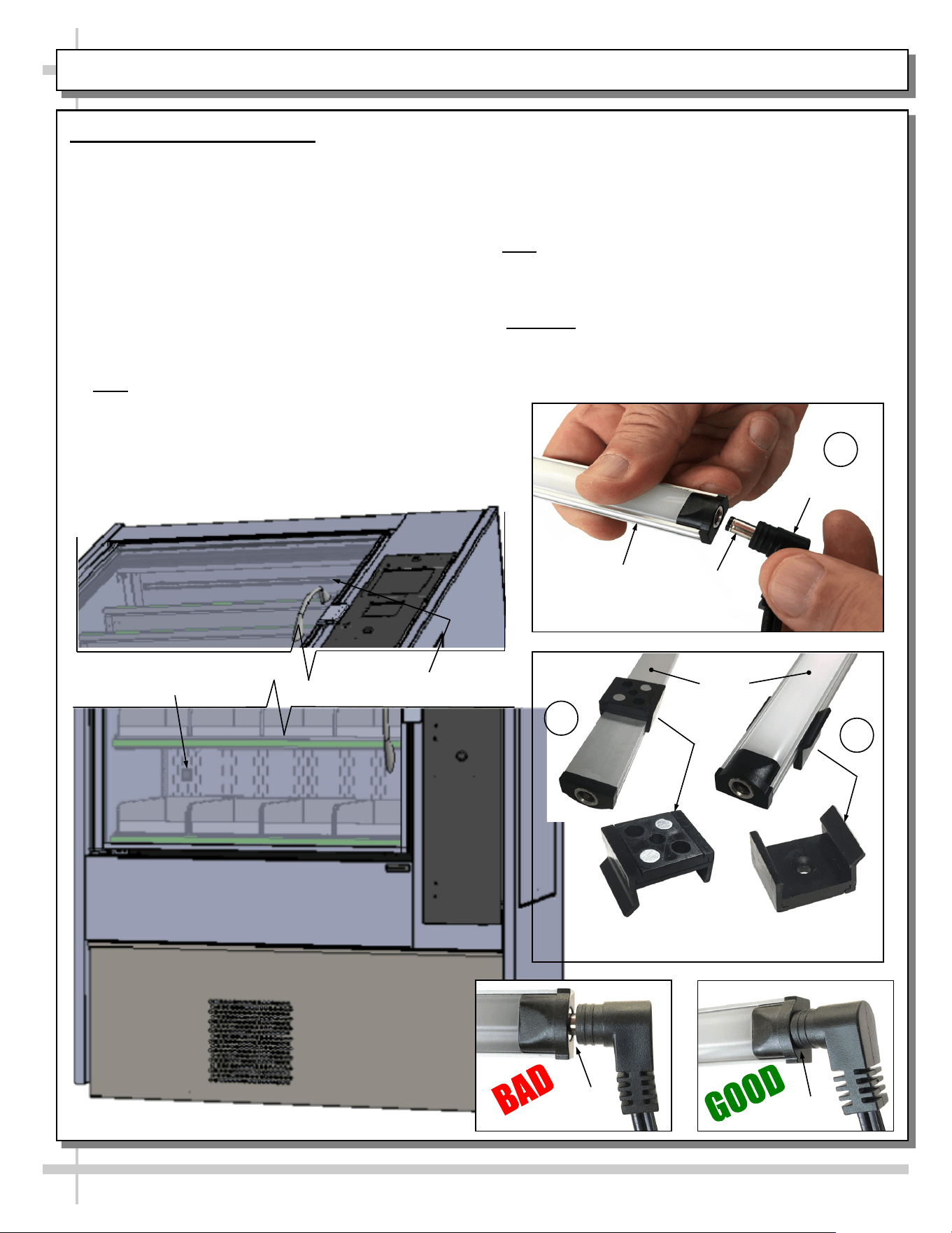
LED Light Fixture in Header
Removal of Faulty LED Light:
• Contact Structural Concepts’ Technical Service
Department for replacement LED light. See last
page of User Manual.
• Turn off LED light switch.
• To remove faulty LED light, follow these steps:
A. Disconnect plug from LED light.
B. Using both hands, grasp LED light assembly
(with its magnetic mounting clips). Pull
downward and off its shelf (or header).
C. Remove magnetic mounting clips from LED
light by pressing against flange part of clip with
thumb.
>> Note: Mounting clips MAY be riveted to header.
Simply remove LED light from mounting clips by
pressing against flange part of clips with thumb.
23
TROUBLESHOOTING (TO BE PERFORMED BY STORE PERSONNEL) - PAGE 4 of 4
Replacement of LED light:
• Attach magnetic mounting clips onto LED light.
• Adjust magnetic mounting clips so they are equally
spaced on LED light.
• Reattach LED light to header.
• Position properly in shelf/header.
>> Note: If mounting clips are riveted to header, attach by
placing LED light in base of clip and then snapping into
clip at FLANGE SIDE.
• Press plug’s barrel-shaped insert deep into LED light.
• Important: If plug is not inserted ALL THE WAY IN the
LED light’s orifice, the light may not energize. See
“BAD” vs. “GOOD” insertion illustrations below.
• Turn LED light switch back on.
--- Lower Case Area Shown Above ---
Magnetic Mounting
Clip View #2
LED
Lights
B
A
Plug
Barrel
Shaped
Insert
LED
Light
C
Magnetic Mounting
Clip View #1
No Gap
Gap
LED Light Switch
LED Light
--- Upper Case Area Shown Below ---
24
CONDITION TROUBLESHOOTING
Head Pressure Too
High
Check that the condensing coil is not dirty or covered.
Check that condensing fans are working.
Perform sub-cooling check and verify that no contaminates are in system.
Check that liquid line filter dryer is not plugged.
Check that close-offs are intact (around condensing coil) and that air is not
recirculating.
Check that store ambient temperature isn’t above maximum allowed.
See OVERVIEW / TYPE / COMPLIANCE / WARNINGS / PRECAUTIONS /
WIRING / PLUGS section in this manual.
Head Pressure Too
Low
If sight glass is part of condensing unit, check if it is flashing or showing low charge.
TROUBLESHOOTING - R-290 CONDENSING SYSTEM (BY TRAINED SERVICE PROVIDERS ONLY)
25
CONDITION TROUBLESHOOTING
Low Suction
Pressure
If sight glass is part of condensing unit, check if it is flashing or showing low charge.
Check that expansion valve (TXV) isn’t restricted. Check element charge.
Check that liquid line or filter isn’t restricted. Check that refrigeration line / courtesy
loop is not kinked.
Check that evaporator fan motor is working.
Check that superheat is between 6 °F to 8 °F.
Check that there is no air recirculation around evaporator coil.
Check that evaporator coil is not iced up.
High Suction
Pressure
Check that the “cooling load” isn’t high. Product must be pre-chilled before placing in
refrigerated section of case.
Check that case is at least 15-feet from exterior doors, overhead HVAC vents or any
air curtain disruption.
Check that unit is not exposed to direct sunlight via windows or any other heat source
(ovens, fryers, etc.).
Check that superheat adjustment isn’t low.
Check TXV bulb installation
a. Poor thermal contact.
b. Warm location.
TROUBLESHOOTING - R-290 EVAPORATOR SYSTEM (BY TRAINED SERVICE PROVIDERS ONLY)
26
SERIAL LABEL LOCATION & INFO LISTED / TECH INFO & SERVICE / REFRIGERATED CASES ONLY
--- Sample Serial Label For Refrigerated Cases ---
MODEL NRS3648RXV-SAMPLE
SERIAL NO. 12345X30DZ098765
888 E. Porter Rd - Muskegon, MI 49441
3048256
Conforms to UL Std. 471
Conforms to NSF/ANSI Stds. 2 & 7
CERTIFIED TO CAN/CSA
STD C22.2 NO 120
ELECTRICAL RATING
REFRIGERANT
DESIGN PRESSURE
MINIMUM CIRCUIT AMPACITY
MAXIMUM OVERCURRENT
120/1/60 16 A
R513A AMOUNT 50 OZ
HIGH 186 LOW 88
20A
20A
Super Heat Temp 6-8 °F FOR PARTS AND SERVICE
Defrost 6 defrosts per day, 45 °F CALL 1-800-433-9490
Serial Label Location & Information Listed /
Technical Information & Service
• Serial labels are affixed at a wide range of places
(on the header, near thermostat, at case rear,
behind panels/toe-kicks, on electrical boxes, etc.).
• Serial labels contain electrical, temperature and
refrigeration information, as well as regulatory
standards to which the case conforms.
• Sample serial label shown below.
• For additional technical information and service, see
the TECHNICAL SERVICE page in this manual for
instructions on contacting Structural Concepts’
Technical Service Department.
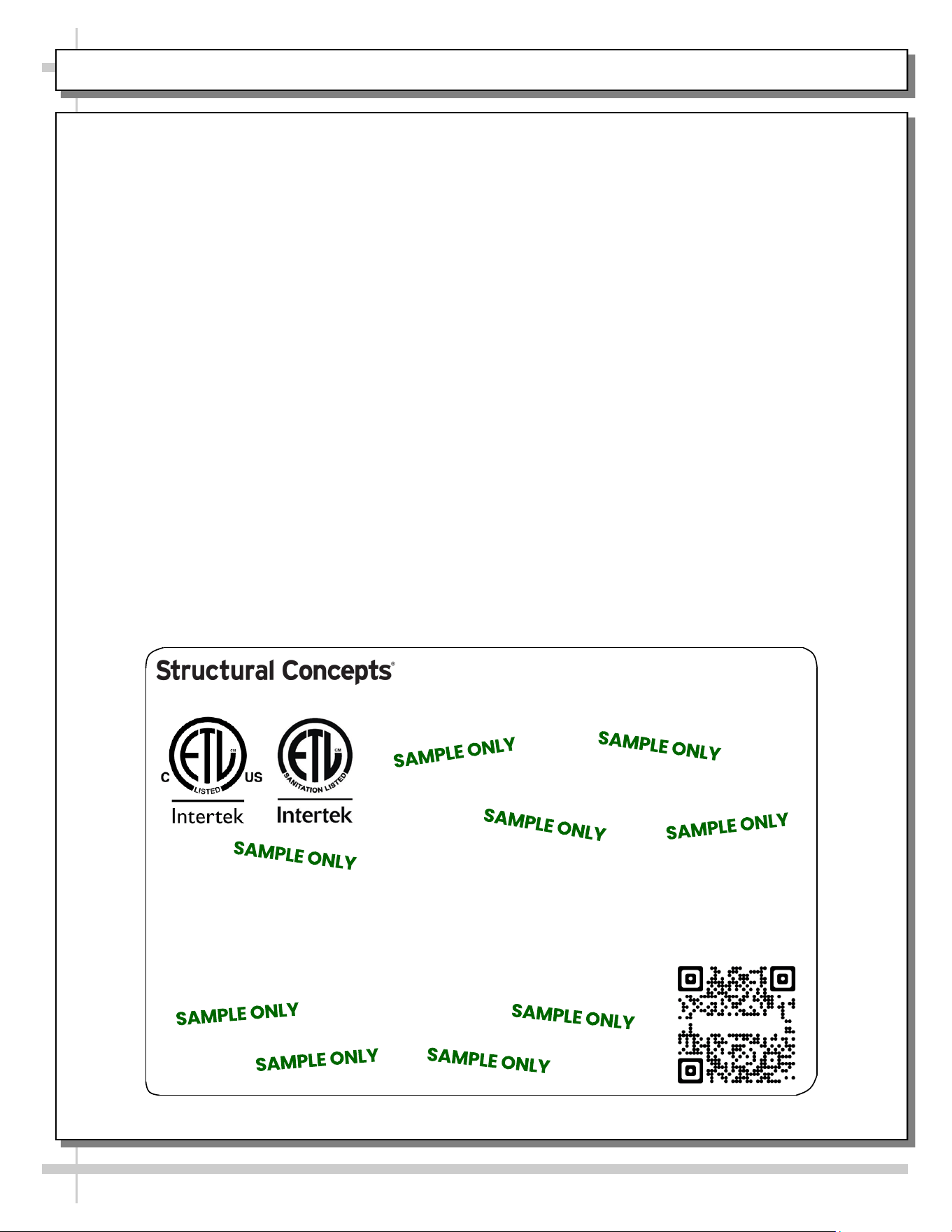
Sample QR Code
SCAN FOR PRODUCT LITERATURE
SAMPLE ONLY
Elevate
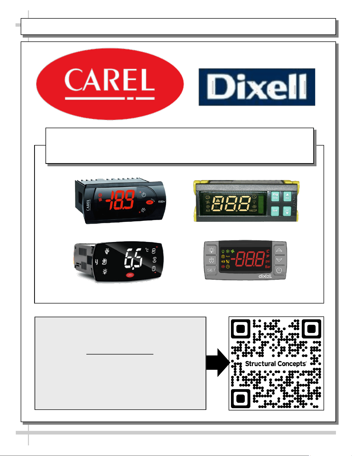
PROGRAMMABLE CONTROLLER (SELECT, CLICK ON OR SCAN QR CODE FOR INFORMATION)
27
Carel® iJF Platform
Carel® PJEZ Platform
Carel® ir33 Platform
Dixell® XM670K-XM679K Platform
To Access Information About The Programmable
Controller That Is Used On Your Case,
Follow These Instructions:
> If Viewing This Document on Smart Phone, Tablet
or Computer, Select/Click On The QR Code at Right.
> If Viewing This Document In Print (Hard Copy),
Scan The QR Code at Right With Your Smart Phone
or Tablet.
Determine Which Programmable Controller Is On Your Case (Controllers
That Are Commonly Used By Structural Concepts Are Shown Below).
Your Particular Programmable Controller May Differ From Units Shown.
INSTANT RETAIL SYSTEMS / STRUCTURAL CONCEPTS TECH. SVC CONTACT INFO & LTD WARRANTY
28
FOR STRUCTURAL CONCEPTS GENERAL MERCHANDISER TECHNICAL SERVICE/WARRANTY
CONTACT INFORMATION: CALL 1 (800) 433-9490 / EXT. 1
--- --- --- --- --- --- ---
DAYS/HOURS AVAILABLE: MONDAY - FRIDAY (CLOSED HOLIDAYS)
8:00 AM to 8:00 PM EST
--- --- --- --- --- --- ---
YOU MUST HAVE THE FOLLOWING INFO AVAILABLE BEFORE CONTACTING INSTANT
RETAIL SYSTEMS OR STRUCTURAL CONCEPTS CORPORATION: SERIAL NO. / MODEL NO. /
STORE NO. / STORE ADDRESS / DETAILS (PHOTOS, LEAK LOCATIONS, PROBLEM/
MALFUNCTION, DAMAGE, STORE’S AMBIENT CONDITIONS, ETC.)
FOR TRAINING ON HARDWARE SETUP, SOFTWARE, CALIBRATION,
CONFIGURATION, ONGOING KIOSK MERCHANDISING, ADMIN FIRST
TIME SETUP, ETC., ACCESS THE QR CODE AT RIGHT.
--- --- --- --- --- --- ---
> IF VIEWING THIS DOCUMENT ON SMART PHONE, TABLET OR COMPUTER,
SELECT/CLICK ON THE QR CODE AT RIGHT WITH YOUR CURSOR.
> IF VIEWING THIS DOCUMENT IN PRINT (HARD COPY), SCAN THE QR CODE
AT RIGHT WITH YOUR SMART PHONE OR TABLET.
--- --- --- --- --- --- ---
FOR INSTANT RETAIL SYSTEMS TECHNICAL SERVICE:
EMAIL SUPPORT@INSTANTRS.COM (PREFERRED) OR CALL 1 (615) 236-6474
TO ACCESS THE LIMITED WARRANTY TO YOUR CASE,
FOLLOW THESE INSTRUCTIONS:
--- --- --- --- --- --- ---
> IF VIEWING THIS DOCUMENT ON SMART PHONE, TABLET OR
COMPUTER, SELECT/CLICK ON THE QR CODE AT RIGHT.
> IF VIEWING THIS DOCUMENT IN PRINT (HARD COPY), SCAN THE
QR CODE AT RIGHT WITH YOUR SMART PHONE OR TABLET.