
WARNING
WARNING
WARNING
WARNING
WARNING
PROBLEM ACTION
1. Unit will not lift rated load. Purge air from hydraulic system by following procedure under
SETUP.
2. Unit will not sustain rated load or feels “spongy” under rated load. Purge air from hydraulic system as above.
3. Unit will not lift to full height. Purge air from hydraulic system as above.
4. Handle tends to raise up while the unit is under rated load. Pump the handle rapidly several times to push oil past ball
valves in power unit.
5. Unit still does not operate. Contact Matco Tools Customer Service.
1-55
1-54
1-53A
1-52
1-51
1-50
1-57
1-56
1-34
1-33
1-49
1-48
1-47
1-46
1-45
1-44
1-73
1-43
1-42
1-41
1-1
2-5
2-6
2-1
2-3
2-4
2-2
1-71
1-69
1-68
1-70
1-69
1-68
1-67
1-66
1-65
1-64
1-3
1-4
1-5
1-6
1-7
1-11
1-10
1-9
1-8
1-2
1-13
1-12
1-14
1-15
1-16
1-17
1-18
1-19A
1-20
1-21
1-22
1-23
1-24
1-25
1-32
1-31
1-30
1-29
1-28
1-27
1-26
1-36
1-37
1-39
1-40
1-38
1-35
1-58
1-59
1-60
1-61A
1-62
2-7
1-72
1-63
3-31
3-4
3-5C
3-5B
3-5A
3-5
3-6
3-7
3-25
3-24
3-23
3-2
3-1
3-16
3-15
3-10
3-12
3-18
3-30
3-32
3-14
3-14
3-17
3-2
3-21
3-27
3-20
3-16
3-26
3-9
3-21
3-15
3-8
3-19
3-3
3-18
3-11
3-17
3-29
3-28
3-22
3-13
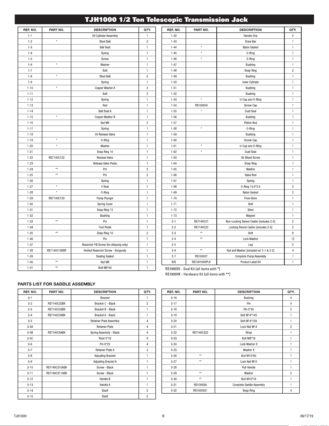
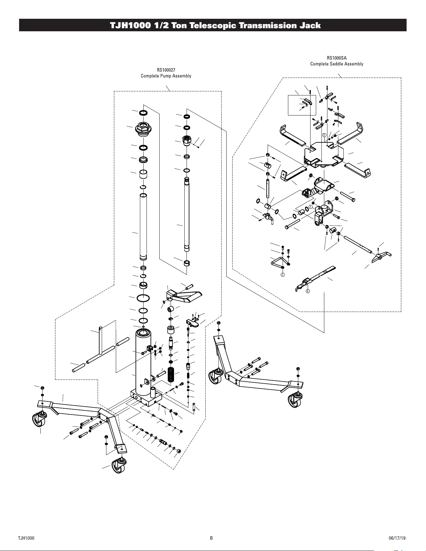
REF. NO. PART NO. DESCRIPTION QTY.
1-42 Handle Grip 2
1-43 Draw Bar 1
1-44 * Nylon Gasket 1
1-45 * O-Ring 1
1-46 * O-Ring 1
1-47 Bushing 1
1-48 Snap Ring 2
1-49 Bushing 1
1-50 Inner Cylinder 1
1-51 Bushing 1
1-52 Bushing 1
1-53 * U-Cup and O-Ring 1
1-54 RS100054 Screw Cap 1
1-55 * Dust Seal 1
1-56 Bushing 1
1-57 Piston Rod 1
1-58 * O-Ring 1
1-59 Bushing 1
1-60 Screw Cap 1
1-61 * U-Cup and O-Ring 1
1-62 * Dust Seal 1
1-63 Air Bleed Screw 1
1-64 Snap Ring 1
1-65 Washer 1
1-66 Valve Rod 1
1-67 Spring 1
1-68 O-Ring 15.6*2.6 2
1-69 Nylon Gasket 2
1-70 Flow Valve 1
1-71 Bolt 1
1-72 Steel 1
1-73 Magnet 1
2-1 RS7140C21 Non-Locking Swivel Caster [includes 2-6] 2
2-2 RS7140C22 Locking Swivel Caster [includes 2-6] 2
2-3 ** Bolt 8
2-4 ** Lock Washer 12
2-5 Leg 2
2-6 ** Nut and Washer [included w/ 2-1 & 2-2] 4
2-7 RS100027 Complete Pump Assembly 1
N/S RSTJH1000PLK Product Label Kit 1
REF. NO. PART NO. DESCRIPTION QTY.
1-1 Oil Cylinder Assembly 1
1-2 * Steel Ball 2
1-3 Ball Seat 1
1-4 Spring 1
1-5 Screw 1
1-6 * Washer 1
1-7 Bolt 1
1-8 * Steel Ball 3
1-9 Spring 1
1-10 * Copper Washer A 2
1-11 Bolt 2
1-12 Spring 1
1-13 Rod 1
1-14 Ball Seat A 1
1-15 * Copper Washer B 1
1-16 Nut M6 2
1-17 Spring 1
1-18 Oil Release Valve 1
1-19 * O-Ring 1
1-20 * Washer 1
1-21 Snap Ring 16 1
1-22 RS7140C122 Release Valve 1
1-23 Release Valve Pedal 1
1-24 ** Pin 2
1-25 ** Pin 2
1-26 Spring 1
1-27 * Y-Seal 1
1-28 * O-Ring 1
1-29 RS7140C129 Pump Plunger 1
1-30 Spring Cover 1
1-31 Snap Ring 15 1
1-32 Bushing 1
1-33 ** Pin 1
1-34 Foot Pedal 1
1-35 ** Snap Ring 16 2
1-36 Pin 1
1-37 Reservoir Fill Screw (for shipping only) 1
1-38 RS7140C138BR Vented Reservoir Screw - Burgundy 1
1-39 Sealing Gasket 1
1-40 ** Nut M8 1
1-41 ** Bolt M8*45 1
REF. NO. PART NO. DESCRIPTION QTY.
3-1 Bracket 1
3-2 RS7140C32BK Bracket C - Black 2
3-3 RS7140C33BK Bracket B - Black 1
3-4 RS7140C34BK Bracket A - Black 1
3-5 Retainer Plate Assembly 4
3-5A Retainer Plate 4
3-5B RS7140CSABK Spring Assembly - Black 4
3-5C Rivet 5*16 4
3-6 Pin 6*25 4
3-7 Retainer Plate A 3
3-8 Adjusting Bracket 1
3-9 Adjusting Bracket A 1
3-10 RS7140C310ABK Screw - Black 1
3-11 RS7140C311ABK Screw - Black 1
3-12 Handle B 1
3-13 Handle A 1
3-14 Shaft 2
3-15 Shaft 2
REF. NO. PART NO. DESCRIPTION QTY.
3-16 Bushing 4
3-17 Pin 4
3-18 Pin 5*30 2
3-19 Bolt M14*145 1
3-20 Bolt M14*139 1
3-21 Lock Nut M14 2
3-22 RS7140C322 Strap 1
3-23 Bolt M8*16 1
3-24 Lock Washer 8 1
3-25 Washer 8 1
3-26 ** Bolt M10*60 1
3-27 ** Lock Nut M10 1
3-28 Pull Handle 1
3-29 ** Washer 2
3-30 ** Bolt M10*16 1
3-31 RS1000SA Complete Saddle Assembly 1
3-32 RS1000331 Snap Ring 4

ADVERTENCIA
ADVERTENCIA
ADVERTENCIA
ADVERTENCIA
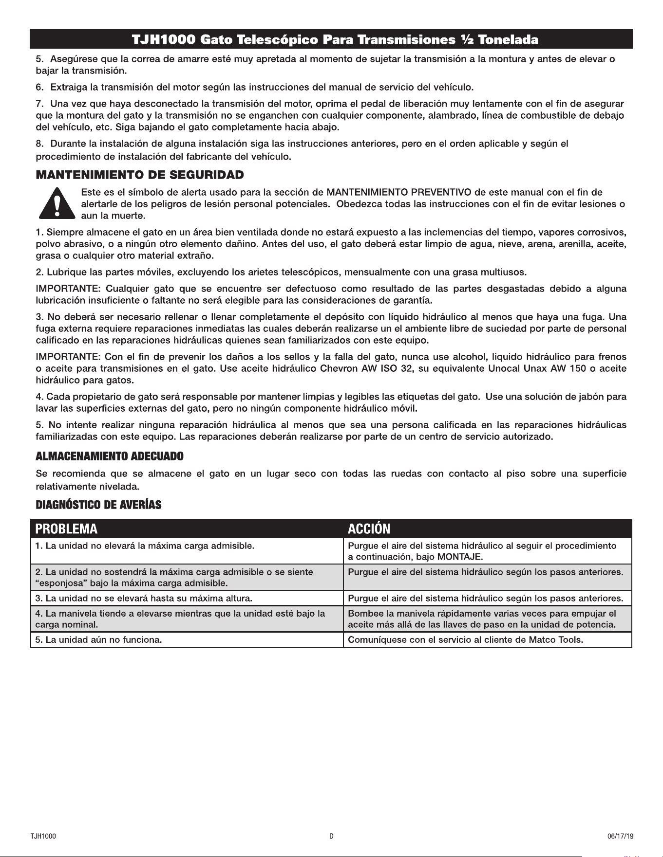
PROBLEMA ACCIÓN
1. La unidad no elevará la máxima carga admisible. Purgue el aire del sistema hidráulico al seguir el procedimiento
a continuación, bajo MONTAJE.
2. La unidad no sostendrá la máxima carga admisible o se siente
“esponjosa” bajo la máxima carga admisible.
Purgue el aire del sistema hidráulico según los pasos anteriores.
3. La unidad no se elevará hasta su máxima altura. Purgue el aire del sistema hidráulico según los pasos anteriores.
4. La manivela tiende a elevarse mientras que la unidad esté bajo la
carga nominal.
Bombee la manivela rápidamente varias veces para empujar el
aceite más allá de las llaves de paso en la unidad de potencia.
5. La unidad aún no funciona. Comuníquese con el servicio al cliente de Matco Tools.
AVERTISSEMENT
AVERTISSEMENT
AVERTISSEMENT
AVERTISSEMENT
AVERTISSEMENT
PROBLÈME ACTION
1. L’unité ne lève pas la charge nominale. Purger l’air du circuit hydraulique en suivant la procédure indi-
quée dans l’INSTALLATION.
2. L’unité ne soutient pas la charge nominale ou semble « spongieuse
» sous la charge nominale.
Purger l’air du circuit hydraulique tel qu’indiqué ci-haut.
3. L’unité ne lève pas à sa pleine hauteur. Purger l’air du circuit hydraulique tel qu’indiqué ci-haut.
4. Le manche tend à s’élever pendant que l’unité porte la charge nomi-
nale.
Pomper le manche rapidement à plusieurs reprises pour pousser
l’huile au-delà des valves à bille dans le vérin.
5. L’unité ne fonctionne toujours pas. Contactez le service à la clientèle Matco Tools.