Page 1
Shipping and Packing List
Package 1 of 1 contains:
1 – Assembled electric heat section
1 – Circuit breaker cover
Check equipment for shipping damage. If you nd any
damage, immediately contact the last carrier.
WARNING
Improper installation, adjustment, alteration, service
or maintenance can cause property damage, personal
injury or loss of life. Installation and service must be
performed by a licensed professional HVAC installer or
equivalent, service agency, or the gas supplier.
CAUTION
As with any mechanical equipment, contact with sharp
sheet metal edges can result in personal injury. Take
care while handling this equipment and wear gloves and
protective clothing.
General Information
These instructions are intended to be a general guide and
do not supersede any local or national codes. Installation
must conform with the local building codes and with the
latest editions of the National Electric Code.
Be sure to disconnect all power to the unit while you install
and service this equipment. Use proper tools and protec-
tive equipment during installation and service.
Installation of air handler with or without optional electric
heat must conform with standards in the National Fire Pro-
tection Association (NFPA) “Standard for Installation of Air
Conditioning and Ventilation Systems NFPA No. 90A,”
and “Standard for Installation of Resident Type Warm Air
Heating and Air Conditioning System, No. 90B,” the man-
ufacturer’s installation instructions, and local municipal
building codes.
Electric Heat Sections
The electric heat sections provide eld-installed electric
heat for air handler units.
The ECBA25 electric heat section is available with 5, 7.5,
10, 12.5, 15 and 20 KW elements.
Refer to the applicable indoor unit product specications
bulletin (EHB) for heat section applications.
Heat Section Installation
WARNING
Before installing or servicing unit, be sure
ALL power to the unit is OFF. More than one
disconnect switch may be present. Electrical
shock can cause personal injury or death!
Before installing the unit, check information on the unit
rating plate to ensure that the unit meets the job specica-
tion, proper electrical power is available, and that proper
duct clearances are maintained.
NOTE – If installing heat sections at the same time as the
air handler unit, install the electric heat section in the air
handler unit before setting the air handler unit and attach-
ing the plenum.
1 - Shut off all power to the air handler unit. More than
one disconnect may be required.
2 - Remove air handler access panel and keep the six
screws to reattach access panel after installing heat
elements.
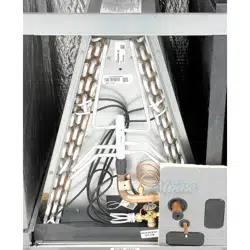
3 - Disconnect any existing eld supply wires and pull
them out of the air handler. Disconnect and remove
wiring harness and fastener (see gure 1). If not
removed, these items will prevent the heat section’s
base from resting properly in the compartment.
4 - Remove the no-heat seal plate in the air handler
frame (see gure 1).
NOTE – If a small heater is installed in the unit, the in-
staller will need to remove the no-heat plate and break it
apart at the perforations and reinstall the two pieces so
the smaller heater can be installed into the unit.
INSTALLATION
INSTRUCTIONS
ELECTRIC HEAT SECTIONS
507848-01 (111003162)
05/2018
ECBA25 Electric Heat Sections
Used with Air Handler Units
THIS MANUAL MUST BE LEFT WITH THE
HOMEOWNER FOR FUTURE REFERENCE
Page 2
NO‐HEAT
SEAL PLATE
REMOVE SCREWS;
THEN REMOVE
NO-HEAT SEAL
PLATE
SEPARATE CONNECTOR;
DISCARD WIRE HARNESS
WIRE
HARNESS
REMOVE FASTENER SECURING WIRES
IF PRESENT
FIGURE 1. Prepare to Install Heat Element
5 - Slide the electric heat section into the air handler. Be
careful that the heating elements do not rub against
the sheet metal opening when they slide into the
air handler. The mounting holes should then line up
with holes in the air handler control box.
6 - Secure the electric heater assembly into place
with the screws that were removed from the heat
element panel. Install two eld-provided #8 SDST
screws in the front of the electric heater assembly
(see gure 2).
INSTALL SCREWS
REMOVED FROM
THE NO-HEAT
SEAL PLATE.
INSTALL 2 FIELD-PROVIDED SCREWS TO SECURE THE
FRONT OF THE HEATER CIRCUIT BREAKER ASSEMBLY TO
THE FRONT FLANGE OF THE AIR HANDLER.
FIGURE 2. Installing the Heat Element Assembly
7 - The air handler’s access panels have a cover
plate that is fastened with a screw and will need to be
positioned to t either one breaker or two, but do not
install the access panel until all electrical connections
have been completed.
WARNING
Foil face insulation must be cut to eliminate the possibility
for any frayed foil to come in contact with any main or low
voltage connections. Insulation must be kept a minimum
of 1/2" away from any electrical connection.
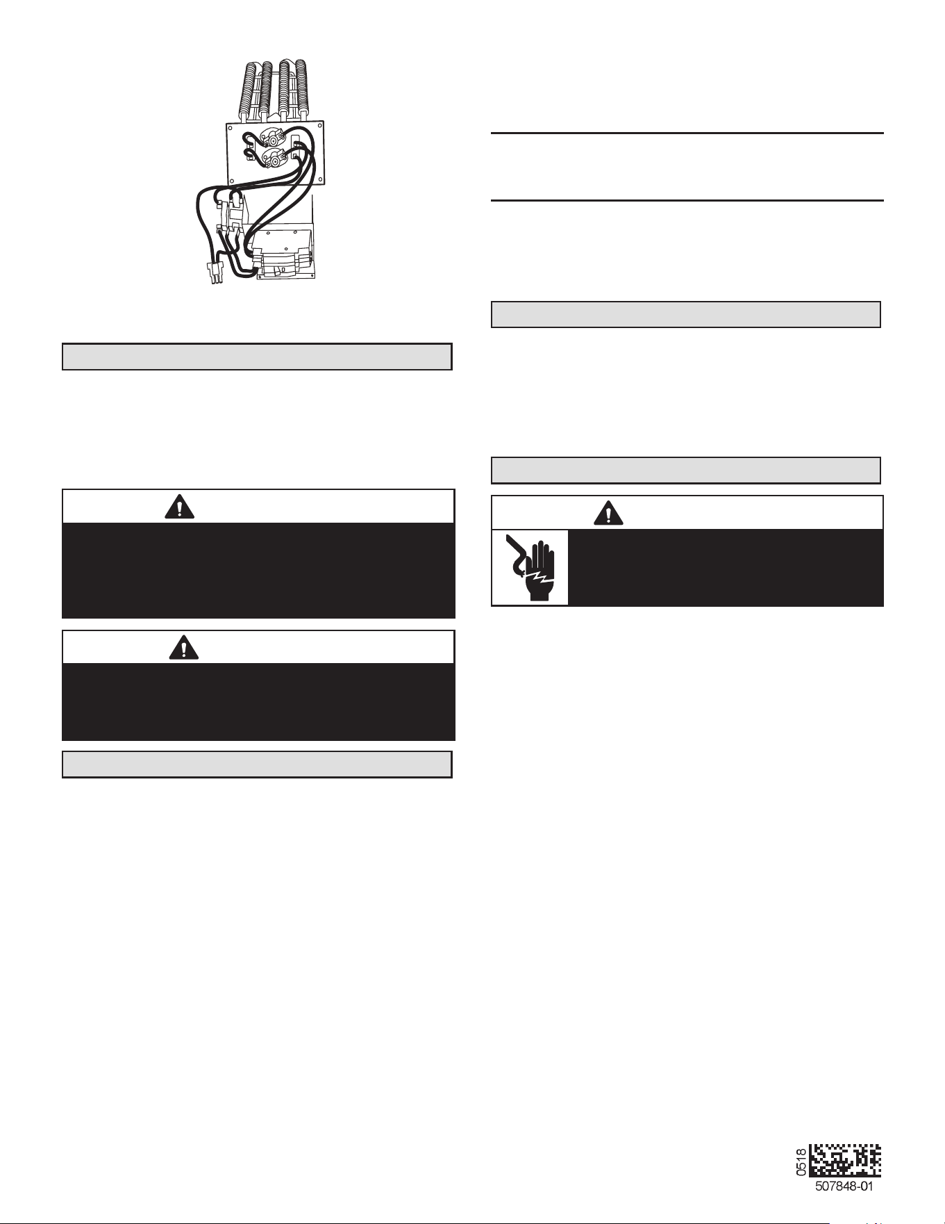
Changing Circuit Breaker Orientation
The air handler comes from the factory ready for hori-
zontal right hand discharge installation. Always rotate the
breaker so up is the ON position in all orientations. The
circuit breaker orientation change is required by UL 1995,
Article 26.18 (25 September 2005).
1 - Locate the one clip located on the right side
(see arrow) of each breaker (see gure 3). The
clip secures the circuit breaker to the mounting
bracket. Pull the clip to release the breaker from
the mounting bracket and rotate the breaker to the
proper postition.
CLIP
BREAKER(S)
MOUNTING
BRACKET
NOTE - There may be only one clip securing
each circuit breaker.
CIRCUIT
BREAKER
FIGURE 3. Circuit Breaker Clip
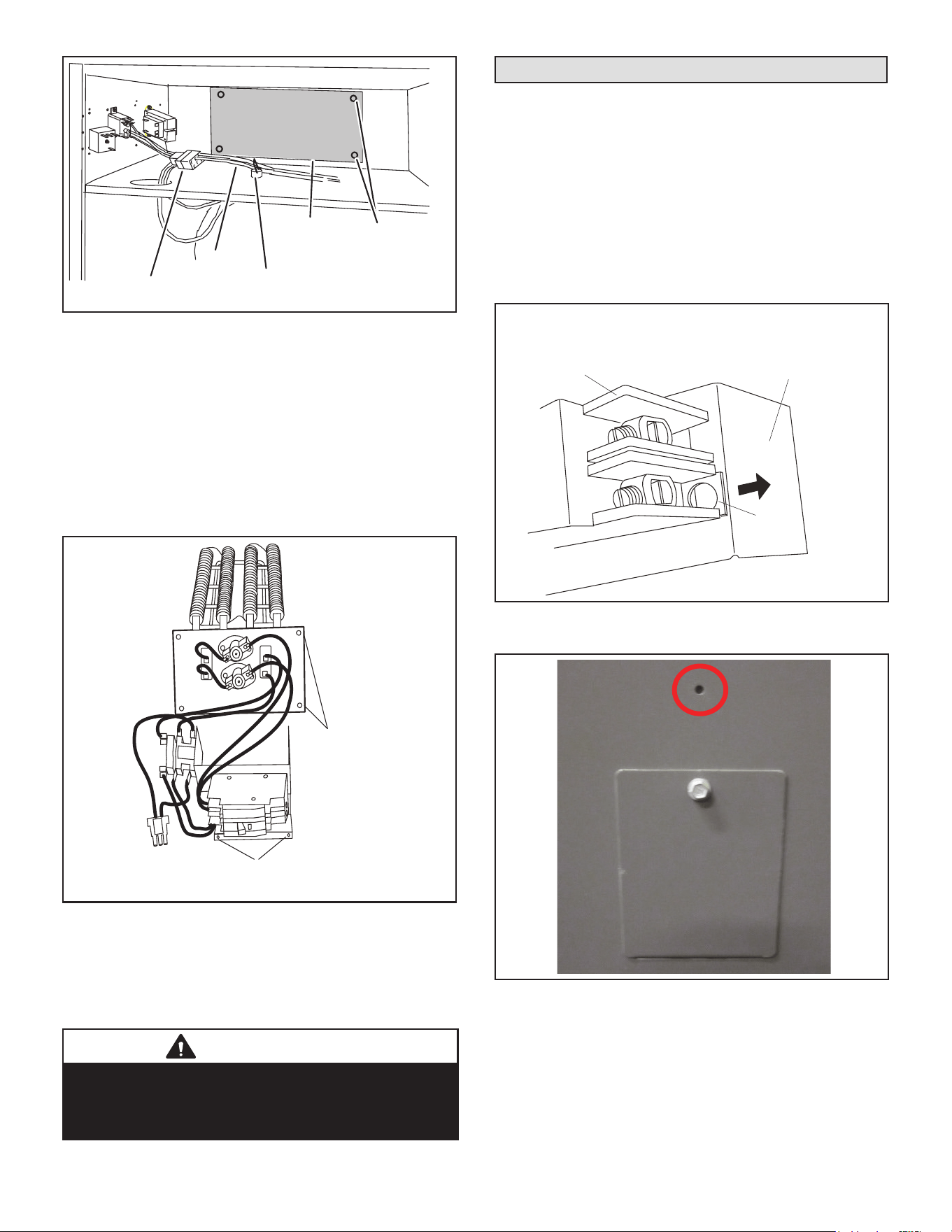
2 - Install the circuit breaker cover plate.
FIGURE 4. Circuit Breaker Cover Plate
NOTE – If electric heat kit has only one circuit breaker, the
breaker cover plate needs to be moved up and installed
over the opening without the circuit breaker. Fasten the
breaker cover plate to the access panel using the circled
hole in gure 4. If the electric heat kit has two circuit break-
ers, the breaker cover plate is not required.
Page 3
Electrical Connections
WARNING
Electric shock hazard! - Disconnect all power
supplies before servicing.
Replace all parts and panels before
operating.
Failure to do so can result in death or
electrical shock.
IMPORTANT
USE COPPER CONDUCTORS ONLY
NOTE – Refer to the nameplate on the air handler unit
for minimum circuit ampacity and maximum overcurrent
protection size.
The air handler units are provided with openings to be
used with 1-1/2 inch trade size (1-31/32 inch diameter)
conduit.
If you want a single point power supply, refer to the name-
plate on the single point power supply accessory for min-
imum circuit ampacity and maximum overcurrent protec-
tion size. Select the proper supply circuit conductors in
accordance with tables 310-16 and 310-17 in the National
Electric Code, ANSI/NFPA No. 70 or tables 1 through 4 in
the Canadian Electric Code, Part I, CSA Standard C22.1.
Refer to gure 13 for typical low voltage eld wiring for
air handler/condensing unit and heat pump applications.
Figure 8 is a diagram of the air handler connections and
the heater high-voltage wiring.
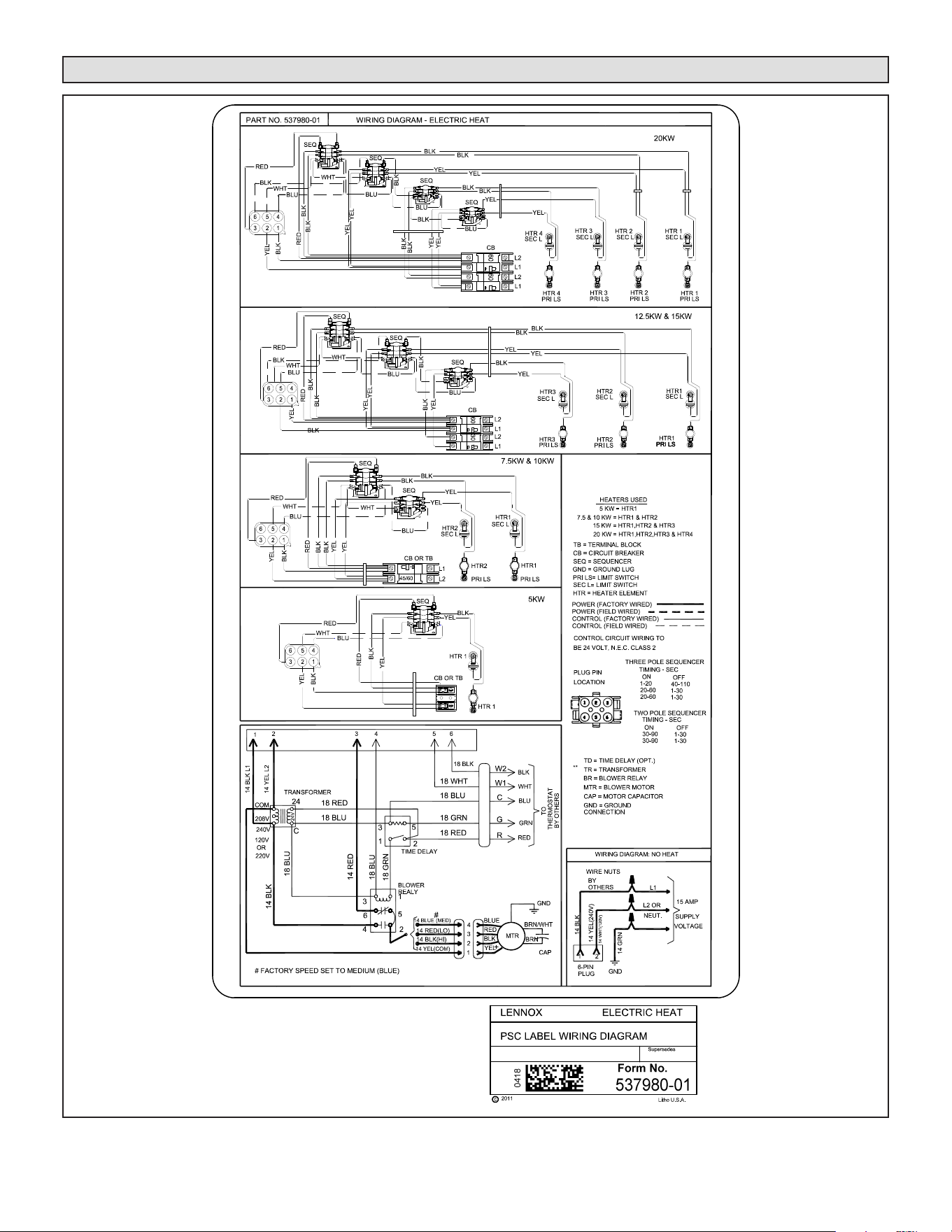
1 - Make wiring connections as follows:
Heaters equipped with circuit breakers —
Connect eld power supply wiring to circuit
breaker(s). Figure 5 shows L1, L2 and ground
(GND) connections for a 2-breaker conguration.
ON
OFF
60
ON
OFF
60
L1
L2
CIRCUIT 1
L1
L2
CIRCUIT 2
GND
208/240 VOLT FIELD
SUPPLY WIRES
Field Supply
Ground Wires
FIGURE 5. Field Power Supply Wiring
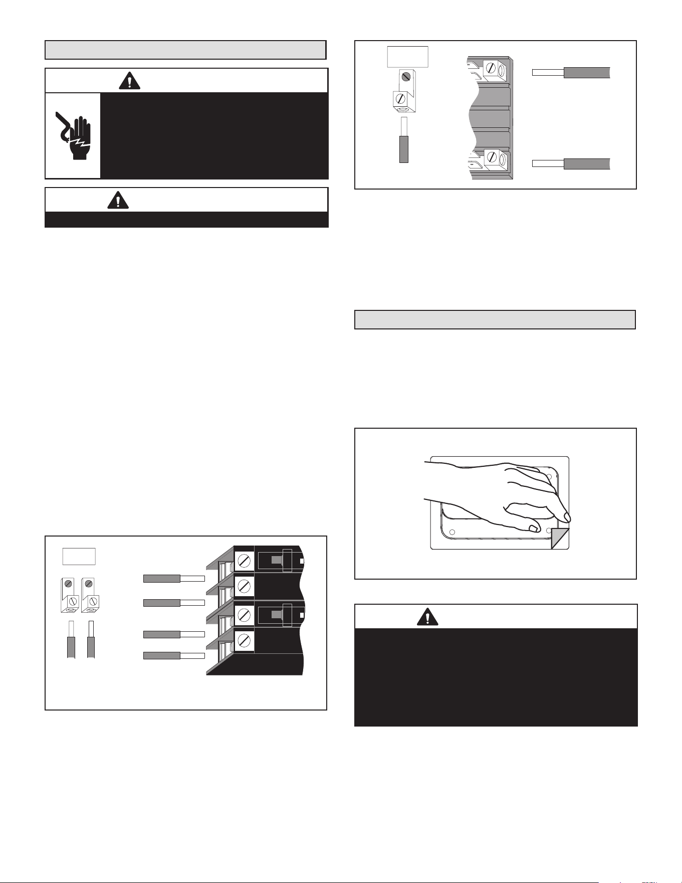
Heaters equipped with terminal blocks — Con-
nect eld power supply wiring to terminal block(s).
Figure 6 shows L1, L2 and ground (GND) connec-
tion for a terminal block conguration.
L1
L2
GND
208/240 VOLT FIELD
SUPPLY WIRES
FIELD SUPPLY
GROUND WIRES
FIGURE 6. Terminal Block Connections
2 - Remove the interface harness from the air handler
unit and connect the 6-pin connector on the heater
assembly to the mating connector on the air handler
unit.
3 - For applications using a two-stage room thermostat
and/or an outdoor thermostat, connect wiring as
shown in gures 9 and 10.
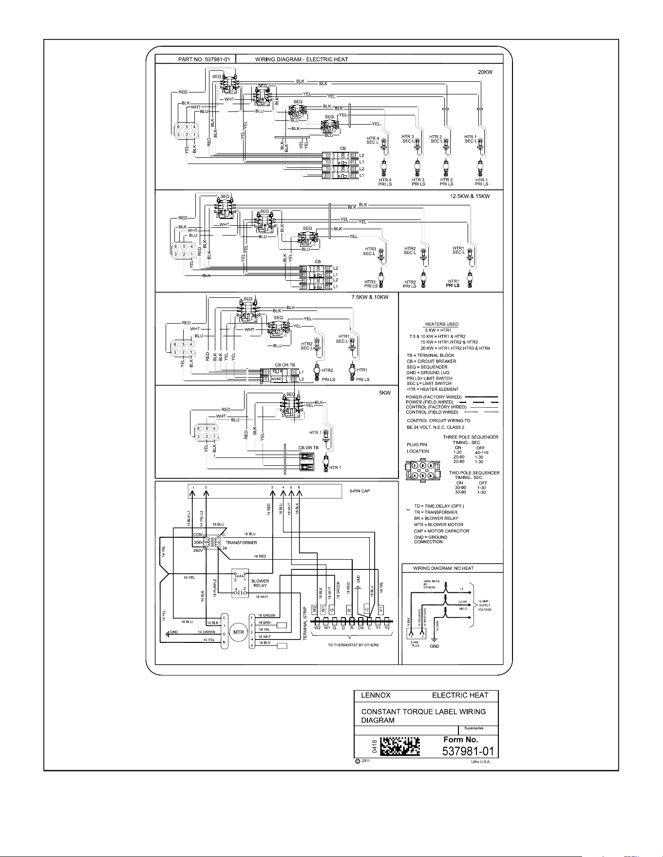
Circuit Breaker Cover Installation
1 - Remove any installed patch plates still present.
2 - Remove paper backing from the adhesive around
the perimeter of the back side of the circuit breaker
cover (gure 7).
3 - Position the breaker cover over the air handler
circuit breaker opening.
CIRCUIT BREAKER COVER
(BACKSIDE)
REMOVE PAPER COVERING
ADHESIVE BACK
FIGURE 7. Remove Paper Cover
IMPORTANT
Conrm air tight seal between breaker cover and air
handler access panel. Apply a thin silicone bead to the
adhesive back seat to ensure air tight seal.
Failure to seal circuit breaker cover will allow warm
moist air to be pulled into control panel which can create
condensation to form on the circuit breaker and other
electrical components within the control panel.

Page 4
Air Handler Speed Connections
When using the electric heat sections with air handler
units, you must adjust the air handler speed according to
the size of electric heat and air handler unit.
• For air handlers with PSC motors, speed tap for electric
heat in upow and horizontal position is medium. Use
high speed tap for downow position.
• For air handlers with variable speed motors, see air
handler instruction for additional information.
See applicable air handler installation instructions for air
handler speed adjustment procedure and location.
Unit Start-Up
1 - After all electrical connections have been completed
and jumpers congured (if required), replace the air
handler compartment access cover.
2 - Restore power to the unit.
3 - If using an electromechanical room thermostat, set
the thermostat heat anticipator to 0.4 amps.
4 - Set the thermostat above room temperature.
5 - Check the heat pump and the heat section for
normal operation.
6 - Set the thermostat to desired setting.
7 - Afx the wiring diagram sticker to air handler scroll,
aligned with circuit breaker unit wiring diagram
sticker.
Page 5
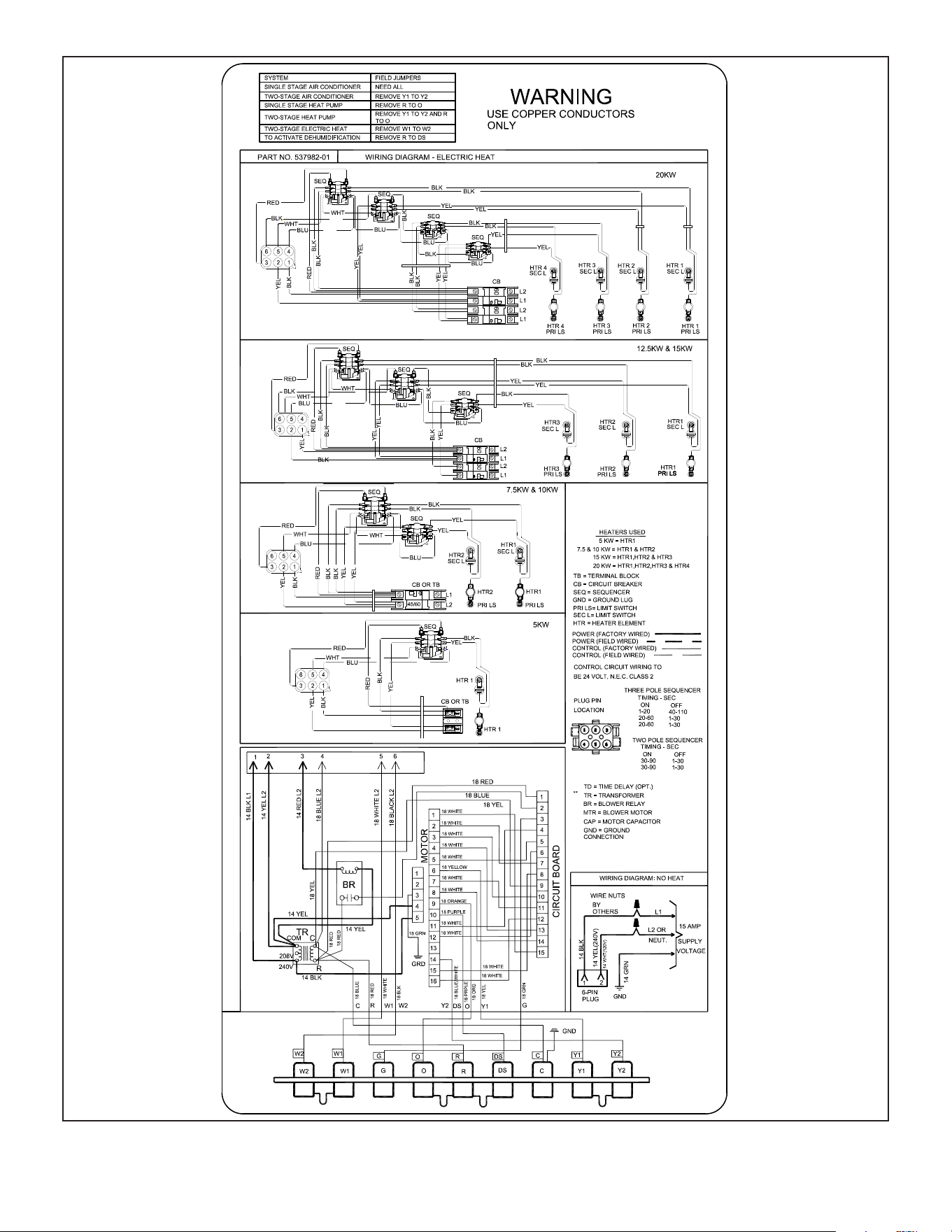
Wiring Diagrams
FIGURE 8. Typical Wiring Diagram – CBA25UH Air Handler with Electric Heat – PSC
Page 6
FIGURE 9. Typical Wiring Diagram – CBA25UH Air Handler with Electric Heat – CT
Page 7
FIGURE 10. Typical Wiring Diagram – CBA25UHV Air Handler with Electric Heat – (Variable-Speed Motor)