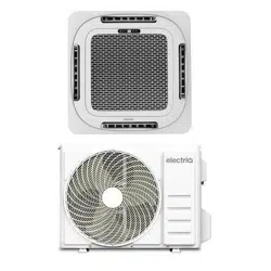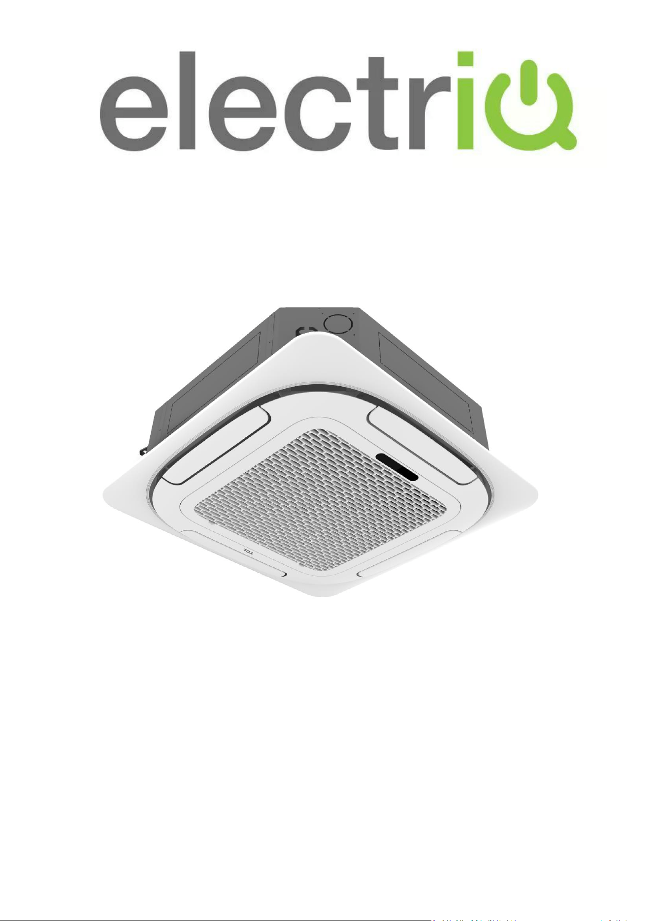
USER MANUAL
iQool-SRC18HP
18,000 BTU Cassette unit
iQool-SRC24HP
24,000 BTU Cassette unit
iQool-SRC36HP
36,000 BTU Cassette unit
SMART WiFi CONTROLLED CEILING MOUNTED
CASSETTE AIR CONDITIONER
Thank you for choosing an electriQ Air Conditioner
Please read this user manual before using this innovative
Air Conditioner and keep it safe for future reference.
2

CONTENTS
3
SAFETY WARNINGS
4
ENERGY SAVING AND UNIT SAFETY PROTECTION TIPS
5
HOW SPLIT AIR CONDITIONERS WORK
6
SYSTEM DIAGRAM
7
PARTS LIST
9
INSTALLATION INFORMATION
10
HOW TO OPERATE YOUR AIR CONDITIONER
11
THE DISPLAY
11
SETTING UP THE REMOTE
11
QUICK START GUIDE
12
REMOTE CONTROL
13
UNDERSTANDING THE FUNCTIONS
15
IMPORTANT INFORMATION
18
SETTING UP THE WiFi APP
19
USING THE WiFi APP
24
CLEANING AND MAINTENANCE
29
TROUBLESHOOTING AND SELF DIAGNOSIS
31
TECHNICAL SPECIFICATION
34
SUPPORT
36

SAFETY WARNINGS
4
IMPORTANT!
• Carefully read the instructions before
operating the unit
• This appliance comprises of an indoor
cassette unit and an outdoor unit. The
indoor unit is designed exclusively for indoor
installations while the external condenser
should be installed outside while still away
from flood water or snow line.
• Always place the unit on a dry and stable
surface. Install the outdoor unit on a wall
with wall-mounting brackets or fix to a floor
slab with special floor mounting slab bolts or
brackets away from flood or snow lines.
• Rating: This unit must be only connected to
a 220-240 V / 50 Hz earthed power source.
• Installation must be in accordance with the
regulations of the country where the unit is
used.
• This appliance is intended for permanent
installation into a fixed structure, and should
not be installed on vehicles.
• The outdoor part of the air conditioner unit
must always be stored and transported
upright, otherwise irreparable damage may
be caused to the compressor; if in doubt we
suggest waiting at least 24 hours before
starting the unit.
• European Union regulations requires for an
F-Gas trained engineer to handle any
operation where non-qualified intervention
could cause fluorinated gas to escape. A
commissioning certificate must be issued
with any installation.
• This air conditioner contains R32 which is a
safe efficient refrigerant which has a lower
environmental burden than traditional
refrigerants.
• The refrigerant used in this air conditioner is
an environmentally friendly hydrocarbon
R32, which has a very low Global Warming
Potential compared to traditional
refrigerants.
• R32 is classed as slightly flammable and as
such naked flames and sources of ignition
should be kept a safe distance from the unit.
If you are in any doubt about the suitability
of your electrical supply have it checked and,
if necessary, modified by a qualified
electrician.
• This air conditioner has been tested and is
safe to use. However, as with any electrical
appliance - use it with care.
• Disconnect the power before dismantling,
assembling or cleaning.
• Never connect the unit to an electrical outlet
using an extension cord. Both the indoor
cassette units and outdoor unit must be
hardwired by a qualified electrician.
• Never operate this appliance if the cord is
damaged. Ensure the power cord is not
stretched or exposed to sharp objects or
edges.
• A damaged supply cord should be replaced
by the manufacturer or a qualified
electrician in order to avoid a hazard.
• Avoid touching any moving parts within the
appliance.
• Never insert fingers, pencils or any other
objects through the guard.
• This appliance is not intended for use by
persons (including children) with reduced
physical, sensory or mental capabilities. It is
also not intended for use by those with a lack
of experience and knowledge, unless they
have been given supervision or instruction
concerning the use of the appliance by a
person responsible for their safety. Do not
leave children unsupervised with this
appliance.
• Do not clean the unit by spraying it or
immersing it in water.
• Any service other than regular cleaning or
filter replacement should be performed by
an authorised service representative or a
qualified air conditioning engineer. Failure to
comply could result in a voided warranty.
• This air conditioner is intended for cooling /
SAFETY WARNINGS
5
heating a room to a suitable level for human
comfort, and should not be used for any
other purpose such as cooling food.
• Avoid restarting the air conditioning unit
unless 3 minutes have passed since being
turned off. This prevents damage to the
compressor.
• Never use the mains as a switch to start and
turn off the air conditioning unit. Use the
provided ON/OFF button located on the
remote control.
• The indoor unit should not be installed in
laundry or wet rooms.
• Diagrams and pictures provided within the
manual are for guidance only. Due to
continual product development, if there is
any variance between the manual and the
product received, the information provided
on the product should be followed.
CAUTION: RISK OF FIRE
READ THE OPERATING
INSTRUCTIONS
READ THE TECHNICAL MANUAL
ENERGY SAVING AND UNIT SAFETY PROTECTION TIPS
• Do not cover or restrict the airflow from the outlet or inlet grills.
• For maximum performance the minimum distance from a wall or objects should be 50cm.
• Keep the filters clean. Under normal conditions, filters should only need cleaning once every four weeks
(approximately). Since the filters remove airborne particles, more frequent cleaning maybe necessary,
depending on the air quality.
• For the initial startup set the fan speed to maximum and the thermostat to 4-5 degrees lower than the
current temperature. After, set the fan switch to low and set the thermostat to your desired setting.
• To protect the unit we recommend not using the cooling mode when the ambient indoor temperature is
higher than 35℃.
• To protect the unit we recommend not using the heating mode when the indoor ambient temperature is
lower than 7℃. Performance will be reduced at lower temperatures.
• Note the manufacturer operating temperature ranges at the end of this user manual.
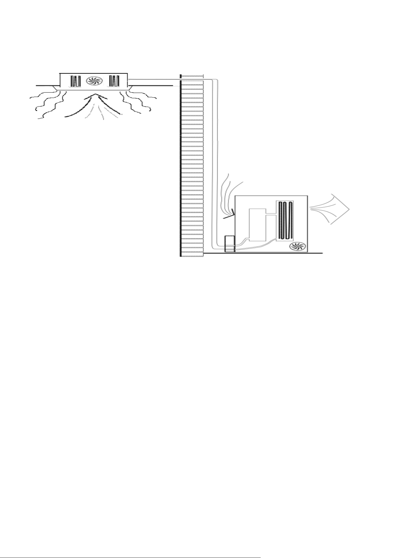
HOW SPLIT AIR CONDITIONERS WORK
6
COOLING MODE
The compressor (6) in the external unit compresses the refrigerant into a high-temperature, high-pressure
gas. When this gas flows along the cooling fins of the condenser (7), heat is exuded and the gas condenses
into a liquid, which is then led to the evaporator (1) in the indoor unit. The liquid expands into a gas at a low
temperature and low pressure. This gas absorbs the warmth of the air in the room, and a fan (3) draws the
air through the filter and over the evaporator (1), blowing the cooled air back into the room. The heat is
moved to the compressor along with the gas. A fan (8) draws air over the condenser and blows the warm air
away.
1. Evaporator
2. Filter
3. Evaporator Fan
4. Gas Line
5. Liquid line
6. Compressor
7. Condenser
8. Condenser Fan
HEAT PUMP MODE
The system operates in reverse: the condenser works as an evaporator, the evaporator as a
condenser: warm air is blown into the room. It is ideal as a maintenance heating when outside
temperature is not too low and when the indoor temperature is more than 7°C.
DRY MODE
As with cooling, the moisture in the air condenses on the cold evaporator at room temperature
acting as a powerful dehumidifier.
.
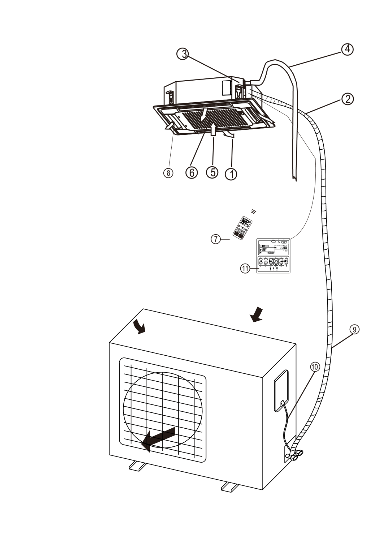
SYSTEM DIAGRAM
7
INDOOR UNIT
OUTDOOR UNIT
NOTE: DIAGRAMS FOR ILLUSTRATIVE PURPOSES ONLY
1
Air Outlet
2
Refrigerant pipes
3
Uplift Pump (Integrated)
4
Drainage Pipe
5
Air Return
6
Filter
7
Remote Control
8
Louvre for airflow
9
Refrigerant pipes
10
Interconnecting Cable
11
Wall Controller (Optional)
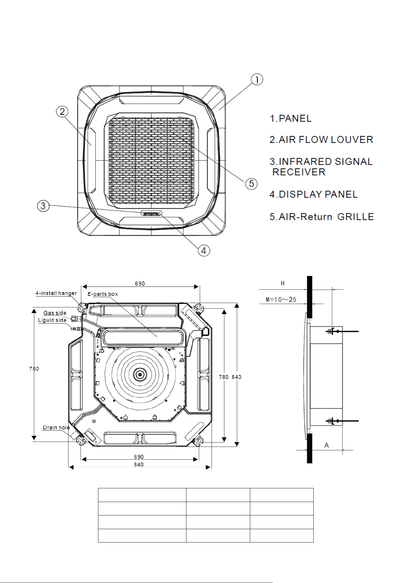
SYSTEM DIAGRAM
8
A
H
iQool-SRC18HP
245
130-135
iQool-SRC24HP
245
130-135
iQool-SRC36HP
290
175-180
CASSETTE UNIT
Do not block the air inlets / outlets on
the cassette, as this will reduce
performance and may lead to damage.
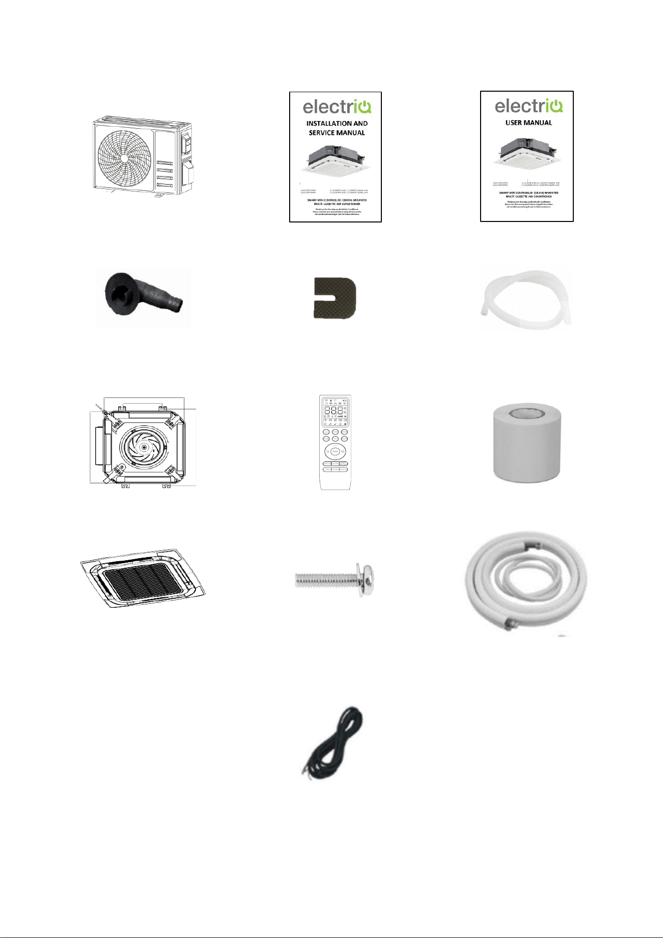
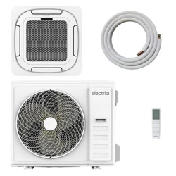
PARTS LIST
9
OUTDOOR UNIT:
Outdoor Unit x 1
Installation Manual x 1
User Manual x 1
Drain Connector x 1
Rubber Feet Pads x 4
Drainage pipe x 1
CASSETTE INDOOR UNIT:
Cassette Unit x 1
Remote Control x 1
PVC Wrap x 1
Panel x 1
(Packaged Separately)
Bolts x 4
(Packaged with Panel)
5m Pipe kit x 1
(Packaged Separately)
5.5m Interconnecting Cable x 1
(Packaged with Pipe Kit)

INSTALLATION INFORMATION
10
This air conditioner must be installed by qualified personnel following the requirements of the
installation and service manual. Installation and servicing of the appliance must only be
conducted by individuals possessing adequate backgrounds and qualifications in electrical,
electronic, refrigerant and mechanical fields. Any attempt to install or repair the appliance may
result in personal injury and property damage.
• Ensure you pass the service and installation manual onto the qualified engineer you have
chosen to install this air conditioner.
• The manufacturer and retailer cannot be responsible for the interpretation of this
information, nor can it assume any liability in connection with its use.
• The units are designed for permanent installation.
• The equipment is designed for domestic or office use and we are not making any
endorsements for use in industrial or maritime environment.
• Do not place near sources of heat, vapours, industrial machine oil or other flammable gases.
• High-frequency waves generated by radio equipment, welders and medical equipment will
interfere with the normal operation of the unit.
• Install this device only when it complies with local/national legislation, ordinances and
standards.
• Check the mains voltage and frequency. This unit is only suitable for an earthed electrical
supply, connection voltage 220-240 V~ / 50 Hz. The information, specifications and
parameter are subject to change due to technical modifications or improvement without
any prior notice. The accurate specifications are presented on the nameplate label.
• Please read this installation manual completely before installing the product.
• When the power cord is damaged, replacement work shall be performed by authorised
personnel only.
• Installation work must be performed in accordance with all European, national and / or local
directives and standards and must be done by authorised personnel only.
• Always make sure to wear the correct personal safety protections such as protective
eyewear, gloves, ear protection etc.
• This air conditioner contains a refrigerant and can be classified as pressurised equipment.
Therefore always contact an authorised air conditioning engineer for installation and
maintenance of the air conditioner.
• The air conditioner must be inspected and serviced on an annual basis by an authorised air
conditioning engineer.
This air conditioner also supports the addition of an optional wired controller
model number: IQOOL-WIREDCASCTRL
Please refer to the manual for the controller for guidance on its operation.
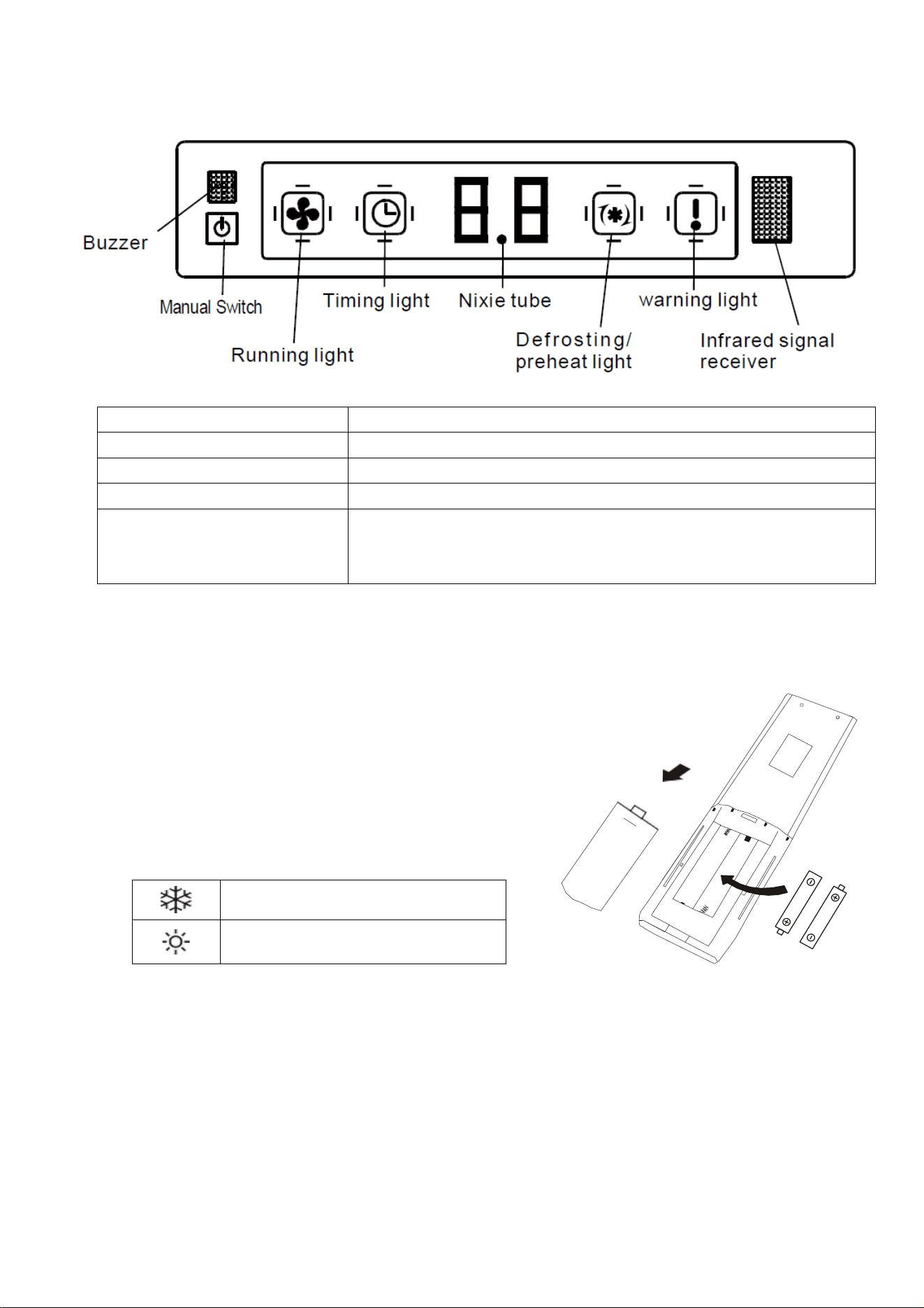
HOW TO OPERATE YOUR AIR CONDITIONER
11
THE DISPLAY
SETTING UP THE REMOTE
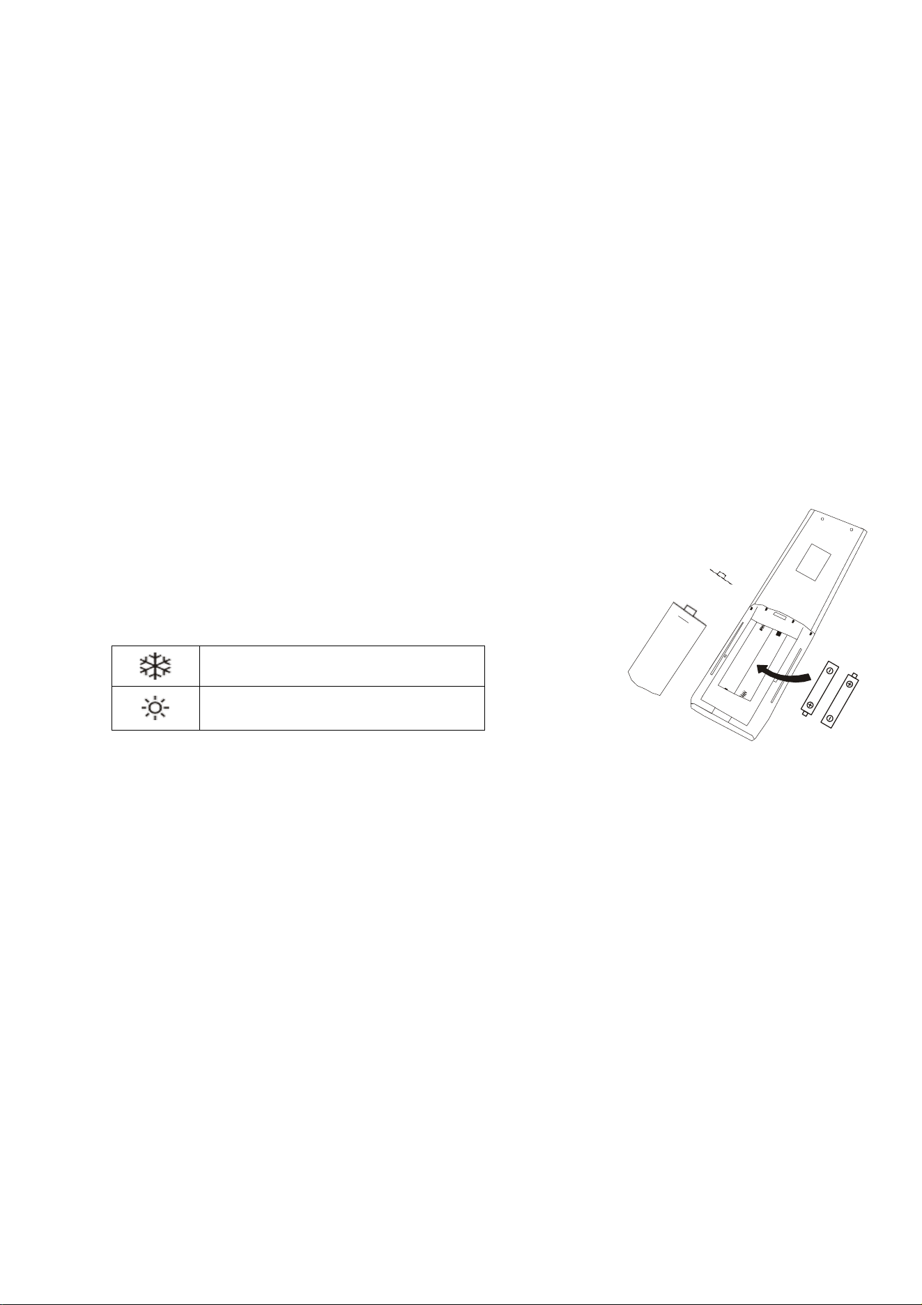
Insert 2 x AAA batteries into the rear of the remote control.
When batteries are first inserted or following changing the
batteries, the remote must be set up for the type of air
conditioner, either COOLING AND HEATING or COOLING ONLY.
As soon as the batteries are inserted, press and hold the MODE
button on the remote until the correct icon is displayed:
COOLING ONLY
HEATING AND COOLING
If COOLING ONLY is selected, the Heating mode will be deactivated.
If the remote is set up for the wrong type of unit, simply remove the batteries and reinsert, before
following the step above.
The remote control has a range of up to 8m. Point the remote control at the receiver in the interior unit.
A beep confirms that the remote-control signal has been received.
MANUAL SWITCH
Can be used to turn the air conditioner on and off
RUNNING LIGHT
Will illuminate when the cassette unit is operating
TIMER LIGHT
Will illuminate when the timer is set
WARNING LIGHT
Will illuminate when an error is detected
PRE-HEAT/DEFROST LIGHT
Will illuminate when the indoor unit is heating the coils,
before warm air is expelled in heating mode, or to prevent
frost in cooling mode.
HOW TO OPERATE YOUR AIR CONDITIONER
12
QUICK START GUIDE
1. With the remote control pointed at the indoor cassette unit, turn the appliance on
using the ON/OFF button on the remote control.
2. Repeatedly press the MODE button to select the desired mode. The
display on the remote will show the symbol to indicate the currently
selected mode:
Auto Mode
Cooling Mode
Dry Mode
Fan only Mode
Heating Mode
3. Use the FAN button to select the fan speed. The fan speed indicator on
the remote will show the currently selected fan speed (5 speeds + Auto):
4. Use the and buttons to select the desired room temperature. The
temperature selected will be displayed both on the remote and the front
panel of the indoor unit.
HOW TO OPERATE YOUR AIR CONDITIONER
13
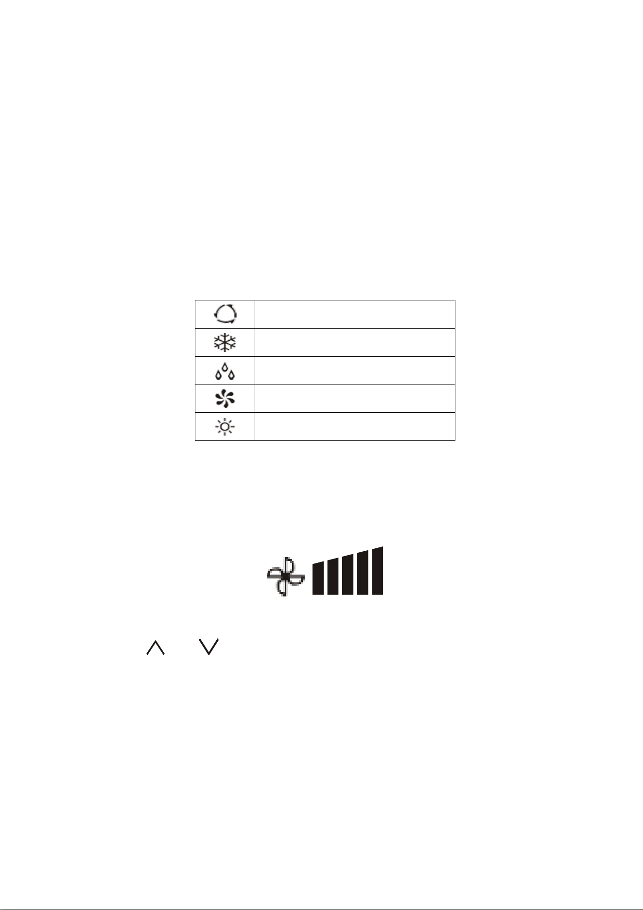
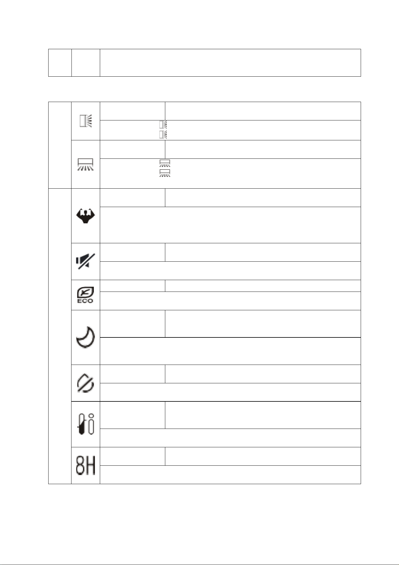
THE REMOTE CONTROL
SYMBOL
MEANING
Battery indicator
Auto Mode
Cooling Mode
Dry Mode
Fan only Mode
Heating Mode
ECO Mode
Timer
Temperature indicator
Fan speed: Auto/low/low-mid/mid/mid-high/high
Mute function
TURBO function
Vertical auto swing
Horizontal auto swing
SLEEP function
Health function (Not Applicable to these models)
I FEEL function
8°C heating function
Signal indicator
Gentle breeze
Child-Lock
Display ON/OFF
Self-Clean function (Not Applicable to these models)
Anti-Mildew
*The functions available on the remote varies depending on the specification and features of the model
of air conditioner purchased.
HOW TO OPERATE YOUR AIR CONDITIONER
14
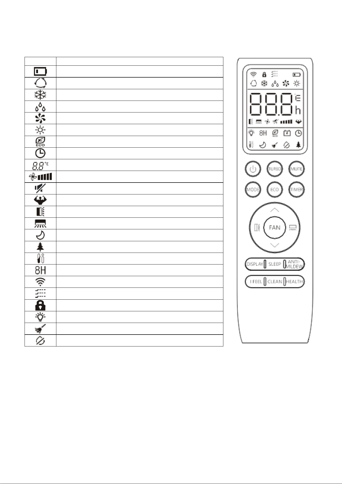
BUTTONS
*The functions available on the remote varies depending on the specification and features of the model
of air conditioner purchased.
See the following pages for more detailed information on the functions
SYMBOL
FUNCTION
Press to turn the air conditioner on and off
Press to increase the desired temperature, or set
the Timer.
Press to decrease the desired temperature, or set
the Timer.
Press to stop or start vertical swing. Used to set the
vertical airflow direction.
Press to stop or start horizontal swing. Used to set
the horizontal airflow direction.
FAN
Press to select the fan speed between:
auto/mute/low/low-mid/mid/mid-high/high/turbo.
TURBO
Press to activate/deactivate the TURBO function.
Press and hold to change between displaying
temperatures in Celsius and Fahrenheit.
MUTE
Press to activate/deactivate the MUTE function.
MODE
Press to select the mode between:
AUTO, COOL, DRY, FAN and HEAT.
ECO
Press to activate/deactivate the ECO function.
Press and hold to activate/deactivate the 8°C
heating function.
TIMER
Press to set an On/Off timer.
DISPLAY
Press to turn the display on and off.
SLEEP
To switch-on/off the function SLEEP.
ANTI-
MILDEW
To activate/deactivate the ANTI-MILDEW function.
I FEEL
To switch-on/off the I FEEL function.
CLEAN
Not used on these models
HEALTH
Not used on these models
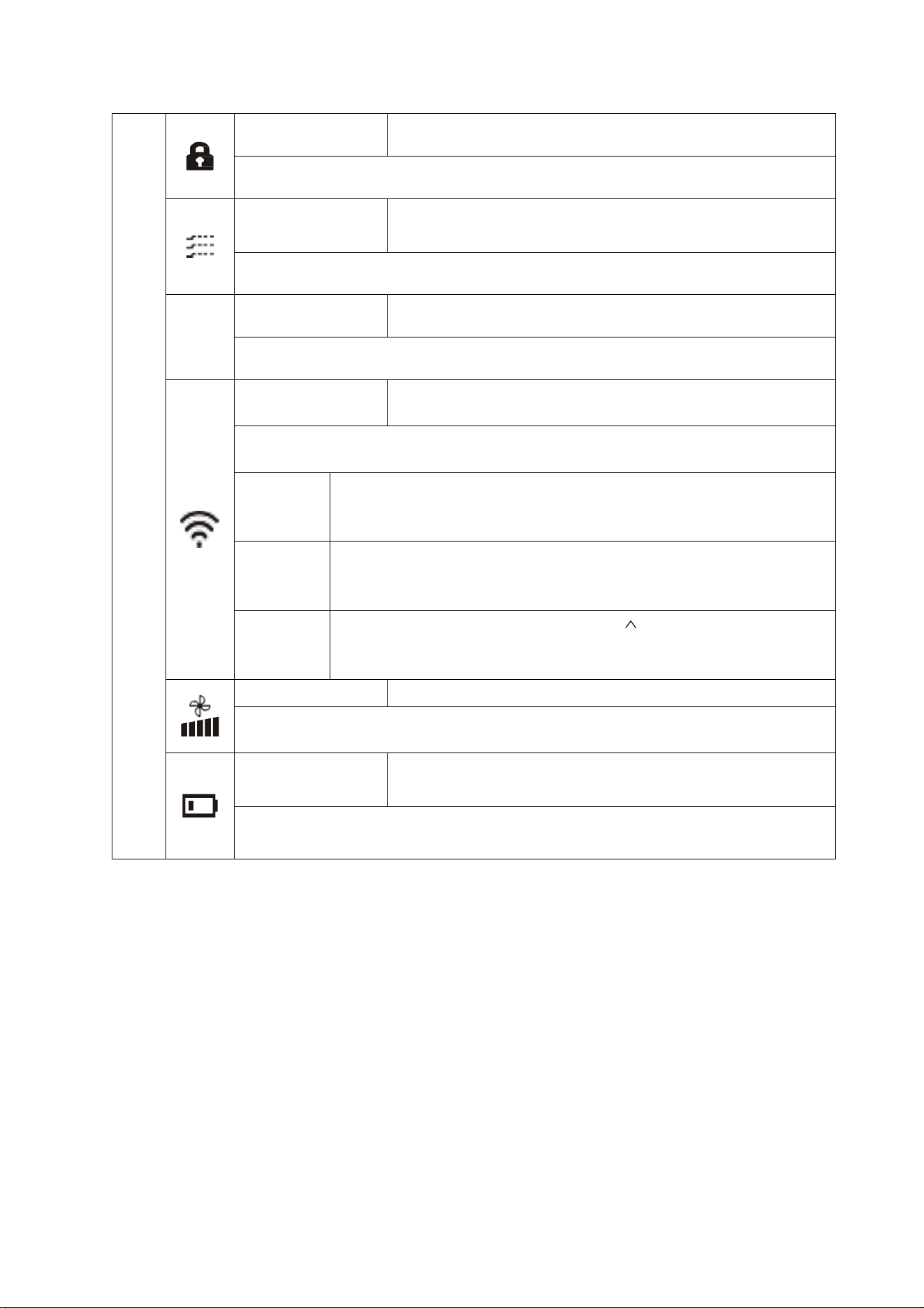
BUTTON COMBINATIONS
MODE +
TIMER
Press together to activate/deactivate the CHILD-
LOCK function.
FAN + MUTE
To activate/deactivate the GENTLE BREEZE
function.
SETTING UP THE WiFi APP
15
MODES
COOLING
Cools the room when the room temperature is above the
desired temperature set. It will also help reduce humidity at
the same time.
1. Press the MODE button until the COOL indicator appears.
2. Set the desired room temperature using the and buttons (16 - 31°C)
3.
Use the FAN button
to set the fan speed.
HEATING
Heats the room when the room temperature is below the
desired temperature set.
1. Press the MODE button until the HEAT indicator appears.
2. Set the desired room temperature using the and buttons (16 - 31°C)
3. Use the FAN button to set the fan speed.
DRY
Removes moisture from the air, by creating a cold surface
within the indoor unit for moisture to condensate on.
1. Press the MODE
button until the DRY indicator appears.
The fan speed will always be low in this mode and the fan speed and temperature
cannot be adjusted in dry mode
FAN
Helps air circulation within the room while acting as a fan, with
no heating or cooling function.
1. Press MODE
button until the FAN indicator appears.
2. Use the FAN button to set the fan speed, cycling through AUTO, MUTE,
LOW, LOW-MID, MID, MID-HIGH, HIGH and TURBO
AUTO
The operating mode will automatically be selected depending
on the room temperature, and aims for a room temperature of
23°C.
1. Press the MODE button until the AUTO indicator appears.
2. The room temperature determines how the air conditioner operates. It is
not possible to change the temperature in this mode the unit will operate to
achieve best performance. The operation logic is as below:
Ambient Temperature
Operation Mode
˂20°C
Heating
20°C - 26°C
Dry
˃26°C
Cool
3. Use the FAN button to set the fan speed.
TIMER
OFF TIMER
Set while the air conditioner is running, so it turns off after the
period of operation set.
1. With the air conditioner running, press the TIMER button.
2. Use the and buttons to set the duration (max 24 hours).
3. Press the TIMER button to confirm.
Once the running time has elapsed, the appliance will switch itself off.
To cancel the timer function before the set time has elapsed, press the TIMER
button again.
ON TIMER
Set while the air conditioner is in standby, so it turns on after
the period set and operates with the previous settings.
1. With the air conditioner in standby, press the TIMER button.
2. Use the and buttons to set the duration (max 24 hours).
3. Press the TIMER button to confirm.
4. The operating parameters can then be adjusted using the and , MODE
and FAN buttons.
SETTING UP THE WiFi APP
16
Once the running time has elapsed, the appliance will start operating.
To cancel the timer function before the set time has elapsed, press the TIMER
button again.
SWING
VERTICAL
The outer flap on the unit will slowly move up and down to
alter the vertical direction of the airflow.
1. Press the button to start the vertical swing.
2. Press the button again to stop the flap in its current position.
HORIZONTAL
The inner louvres on the unit will slowly twist left and right to
alter the horizontal direction of the airflow.
1. Press the button to start the horizontal swing.
2. Press the button again to stop the internal louvres in their current
position.
ADDITIONAL FUNCTIONS
TURBO
Operates at highest fan speed for 15 minutes to maximise
performance, when heating of cooling a room.
1. Press the TURBO button to activate turbo mode
2. The fan and compressor will run at maximum speed for 15 minutes, before
returning to their previously set levels.
To cancel turbo mode, press the TURBO button again.
MUTE
Operates at lowest fan speed to minimise the operating noise
of the indoor unit.
1. Press the MUTE button to activate the function.
2. Press the MUTE button again to deactivate the function
ECO
Automatically adjusts the settings to reduce energy usage.
1. Press the ECO button to activate the function.
2. Press the ECO button again to deactivate the function
SLEEP
Operates at lowest fan speed to minimise the operating noise
of the indoor unit for 10 hours, before returning to normal
operation.
1. Press the SLEEP button to activate the function.
The function will automatically stop after 10 hours, but can be cancelled earlier by
pressing the SLEEP button.
ANTI-MILDEW
The indoor unit will operate in fan mode for 15 minutes to
remove any moisture, before turning off.
1. Press the ANTI-MILDEW button to activate the function.
The function will automatically stop after 15 minutes.
I FEEL
The room temperature is measured by the remote control
instead of the indoor unit, allowing you to optimise the
temperature to ensure comfort.
1. Press the I FEEL button to activate the function.
2. Press the I FEEL button again to deactivate the function
8°C HEATING
A 30 minute program designed to remove dirt and bacteria
from within the indoor unit.
1. Press and hold the ECO button for 3 seconds to enter the mode.
Press and holf the ECO button for 3 seconds to exit the mode.
SETTING UP THE WiFi APP
17
ADDITIONAL SETTINGS /
FEATURES
CHILD LOCK
Locks the buttons on the remote to prevent the accidental
alteration of settings.
1. Press the MODE and TIMER buttons together to activate the function
2. Press them again to cancel the function.
GENTLE
BREEZE
Operates with the flap on the indoor unit closed, to provide a
gentle breeze into the room.
1. Press the FAN and MUTE buttons together to activate the function
2. Press them again to cancel the function.
°C/°F
TEMP UNIT
Change the temperature that displays on the remote and unit
between Celsius and Fahrenheit.
1. Hold the TURBO button for 5 seconds to change the temperature display
2. Repeat to change back.
WiFi SETUP
Used to connect the indoor unit to your SMART app.
Each indoor should be set up separately
There are 3 options for activating the WiFi setup, as shown below. For more
detail see the WiFi connection section of this manual.
Method 1
1. Press the DISPLAY button 6 times within 8 seconds.
The unit will then bleep 3 times and CF or AP will be shown on
the indoor display.
Method 2
1. Press the ECO button 6 times within 8 seconds.
The unit will then bleep 3 times and CF or AP will be shown on
the indoor display.
Method 3
1. Press and hold the MODE and buttons for 3 seconds.
The unit will then bleep 3 times and CF or AP will be shown on
the indoor display.
FAN SPEED
In most modes the fan speed can be adjusted.
1. Press the FAN button to change between the fan speeds, the available
options are: auto, mute, low, low-mid, mid, mid-high, high, turbo
BATTERY
LEVEL
The remote will show you the current battery level
When the battery level is showing as low, the batteries in the remote control should
be changed, to ensure you can continue to operate the air conditioner.

SETTING UP THE WiFi APP
18
IMPORTANT INFORMATION
HEATING MODE
When the air conditioner is placed in heating mode, the indoor unit will appear to be inactive
while it follows its pre-heat procedure to heat the evaporator coils. Once the coils have heated,
the indoor fan will start to run. This process usually takes 1 – 3 minutes, and is designed to
ensure that cold air is not circulated.
During heating mode, the appliance can automatically activate a defrost cycle, which is
essential to clean the frost on the condenser so as to recover its heat exchange function. This
procedure usually lasts for 2-10 minutes. During defrosting, the fan in the indoor unit will stop
operation. After defrosting, it will return to HEATING mode automatically.
AUTO RESTART
The air conditioner will automatically restart when electricity is restored after a power cut. If in
doubt, check the settings.
RANGE OF INTERNAL THERMOSTAT
The internal thermostat can be set at a desired temperature between 16 and 31°C. Note that
whether the desired value is achieved depends on the room size, temperature and insulation of
the room.
RANGE OF HEAT PUMP FUNCTION
The heat function can be used when the external ambient temperature is above -20°C. The
performance of the heat pump will degrade with lowering external temperatures. Please note
the performance will reduce when the outdoor temperature drops below 5°C.
CAPACITY
The required cooling or heating capacity depends greatly on the location and/or use of the
room where the air conditioner is installed. Strong sunlight and the presence of people, lights
or equipment creates an additional heat load. Normal living spaces require about 350 Btu per
square meters of floor surface. In strong sunlight or if other sources of heat are present, this
may be as much as 1200 Btu per sqm.
Tip: On warm days, let the air conditioner cool the room as much as possible during the night
and keep the temperature constant from night to daytime.

SETTING UP THE WiFi APP
19
BEFORE YOU START
• Ensure your router provides a standard 2.4ghz connection.
• If your router is dual band ensure that both networks have different network names (SSID). The
provider of your router / Internet service provider will be able to provide advice specific to your
router.
• Ensure the router is as close as possible to the indoor unit during setup.
• Once the app has been installed on your phone, turn off the data connection, and ensure your phone
is connected to your router via WIFI.
DOWNLOAD THE APP TO YOUR PHONE
Download the ”SmartLife” app, from your chosen app store, using the QR codes below, or by
searching for the app in your chosen store.
Android
IOS
The unit can also be controlled using the “Tuya Smart” app which is also available in the app
stores. We would advise on using the version above which is optimised for use with your air
conditioner as we cannot guarantee the correct functionality of all features when other
versions are used.
Android
IOS
SETTING UP THE WiFi APP
20
CONNECTION METHODS AVAILABLE FOR SETUP
The air conditioner has two different setup modes, Quick Connection and AP (Access Point). The quick
connection is a quick and simple way to set the unit up. The AP connection uses a direct local WiFi
connection between your phone and the air conditioner to upload the network details.
Please ensure your device is in the correct WIFI connection mode for the connection type you are
attempting, the flashing of the WIFI light on your air conditioner will indicate this.
CONNECTION TYPE
DISPLAY OF INDOOR UNIT SHOWS
Quick Connection
CF
AP (Access Point)
AP
RESETTING THE WiFi CONNECTION ON THE INDOOR UNIT
There are 3 different methods for resetting the WiFi module on the indoor unit, which can be done using
your mobile phone:
Method 1
Press the DISPLAY button 6 times within 8 seconds.
Method 2
Press the ECO button 6 times within 8 seconds.
Method 3
Press and hold the MODE and buttons for 3 seconds.
Once the above has been followed, it will bleep 3 times, you should allow upto 10 seconds for the
connection mode to be displayed on the indoor unit before continuing connection.
If no connection is made within 2 hours, the WiFi will automatically turn off, and the connection should
be reset following the steps above to reactivate the function.
Please note: Each indoor unit is classed as a separate device within the app and as such the
connection process should be repeated for each indoor unit.
CHANGING BETWEEN CONNECTION TYPES
Changing the air conditioner between the two WiFi connection modes is exactly the same process as
resetting the connection:
Method 1
Press the DISPLAY button 6 times within 8 seconds.
Method 2
Press the ECO button 6 times within 8 seconds.
Method 3
Press and hold the MODE and buttons for 3 seconds.
SETTING UP THE WiFi APP
21
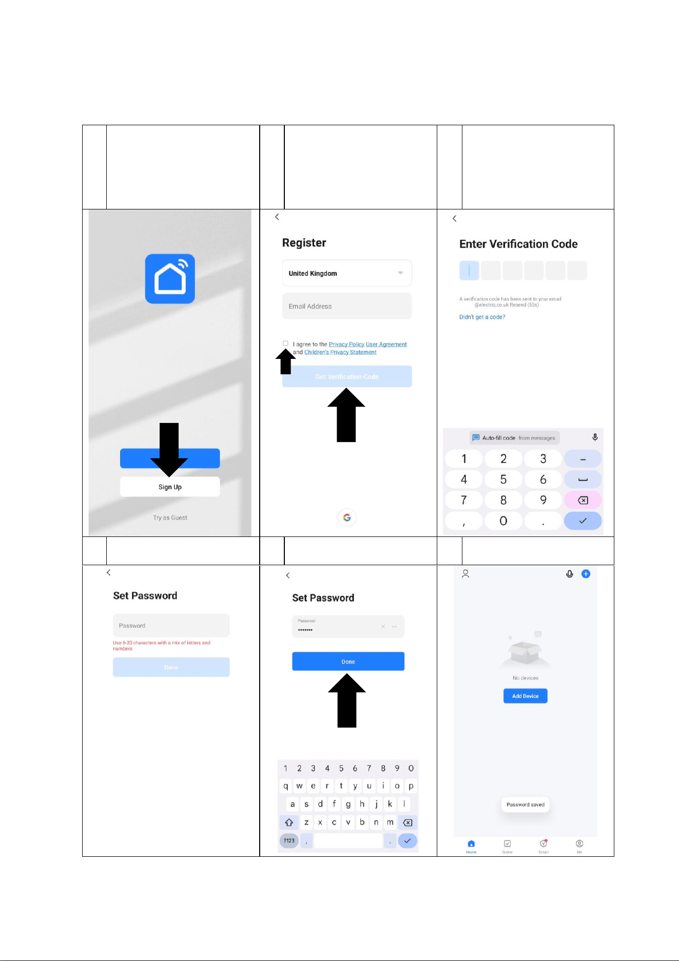
REGISTER THE APP
Upon the first use, an account will need to be registered which can be done as below:
1
Press the Sign Up button at
the bottom of the screen.
2
Change the country (If
required) before entering
your email address, ticking
the checkbox, and pressing
the Get Verification Code
button.
3
A verification code will be
sent to your email address.
Type it into the boxes.
4
Create a password following
the requirements.
5
Once it has been entered,
press Done.
6
The app will then load to the
main device screen.
SETTING UP THE WiFi APP
22
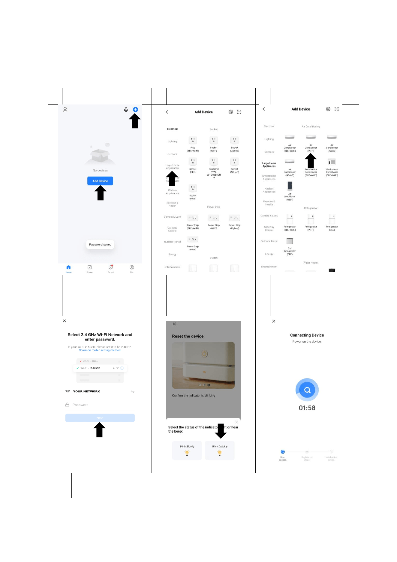
CONNECTING USING QUICK CONNECTION MODE
Before initiating the connection, make sure the unit is in standby mode, with the display on the indoor unit
showing CF. If not follow the instructions for changing the connection mode. You should also ensure your phone is
connected to the WiFi network. (We advise turning mobile data off during setup)
1
Press on Add Device, or the +
in the top right corner.
2
Press the Large Home
Appliances tab on the left
3
Press on Air Conditioner
(WiFi)
4
Ensure your WiFi network is
shown before entering your
password*, and pressing
Next.
5
As you have already prepared
your air conditioner, Press
Next On the screens asking to
Reset the device. Then select
Blink Quickly.
6
The app will now attempt to
connect your air conditioner
to the internet.
7
Once successfully added the app will take you to the device screen.
If connection fails, retry connection using the quick connection (CF) mode, or alternatively follow the
Access Point (AP) mode connection method.
* Passwords are case sensitive, and often on a
label attached to your router.
Instructions are for guidance only, due to
continual development of the app, the process
may differ from the above.
SETTING UP THE WiFi APP
23
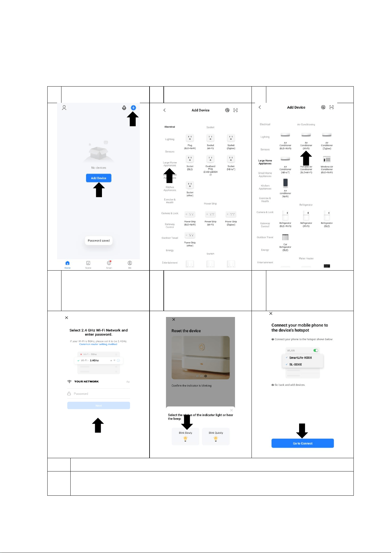
CONNECTING USING ACCESS POINT (AP) MODE
Before initiating the connection, make sure the unit is in standby mode, with the display on the indoor unit
showing AP. If not follow the instructions for changing the connection mode. You should also ensure your phone
is connected to the WiFi network. (We advise turning mobile data off during setup)
1
Press on Add Device, or the +
in the top right corner.
2
Press the Large Home
Appliances tab on the left
3
Press on Air Conditioner
(WiFi)
4
Ensure your WiFi network is
shown before entering your
password*, and pressing
Next.
5
As you have already prepared
your air conditioner, Press
Next on the screens asking to
reset the device. Then select
Blink Quickly.
6
Use the Go to connect button
to leave the app, and connect
your phone to the WiFi
hotspot created by the air
6
Return to the app and it will attempt to connect your air conditioner to the internet.
7
Once successfully added the app will take you to the device screen.
If connection fails, retry connection using the Access Point (AP) mode, or alternatively follow the Quick
Connection (CF) mode connection method.
* Passwords are case sensitive, and often on a
label attached to your router.
Instructions are for guidance only, due to
continual development of the app, the process
may differ from the above.
USING THE WiFi APP
24
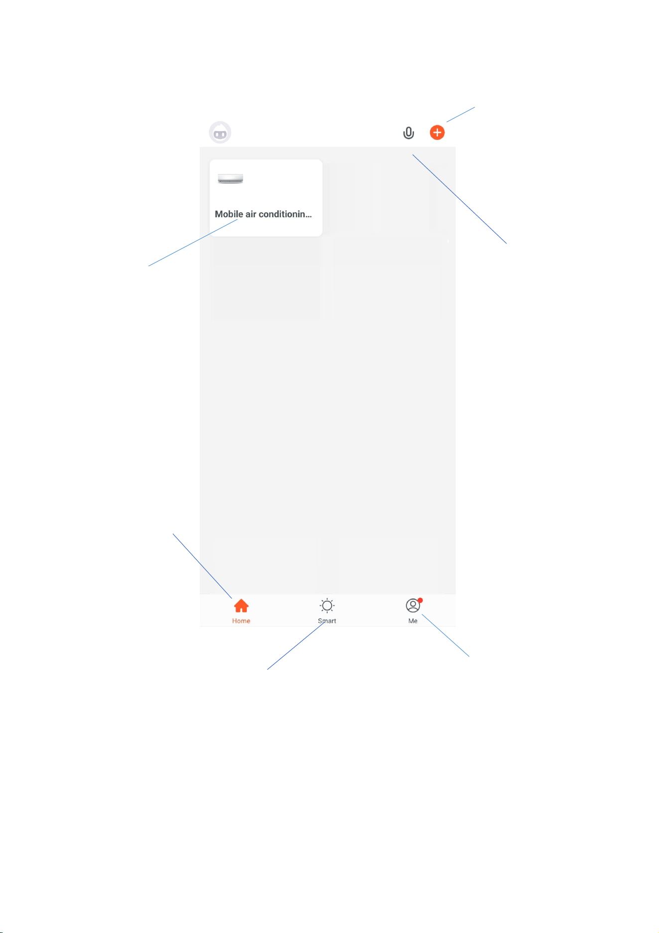
THE HOME SCREEN
Each device has its own entry on the home screen to allow the user to either quickly turn the
unit on or off, or to enter the device screen to make other changes.
Smart Scene: Allows you to
program intelligent behavior
based on the internal and
external environment
Add Device: Add a device
to the app, and go through
the setup process.
Profile: Provides the
option for changing
settings, and adding
devices using a QR code
provided by a friend.
Your Device: Press
to enter the device
screen.
Voice Control: Use to
give verbal instructions
to the app.
Home: Return to this
screen when within
the Smart or profile
tabs.
USING THE WiFi APP
25
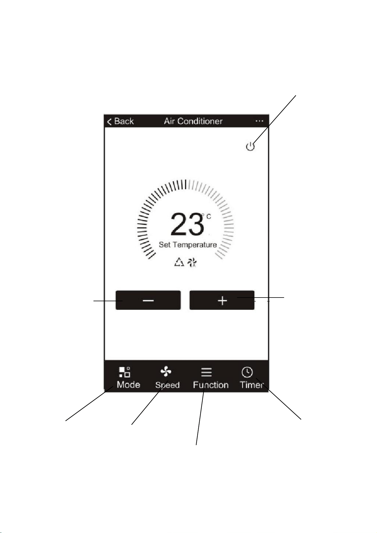
THE DEVICE SCREEN
Increase desired
room temperature
Decrease desired
room temperature
Turn Indoor
unit on and
off
Change
between Auto,
Cool Heat, Dry
and Fan modes.
Adjust the
fan speed.
Activate additional
functions such as Swing,
Turbo, Sleep and Eco Mode
Set an off or on timer.
USING THE WiFi APP
26
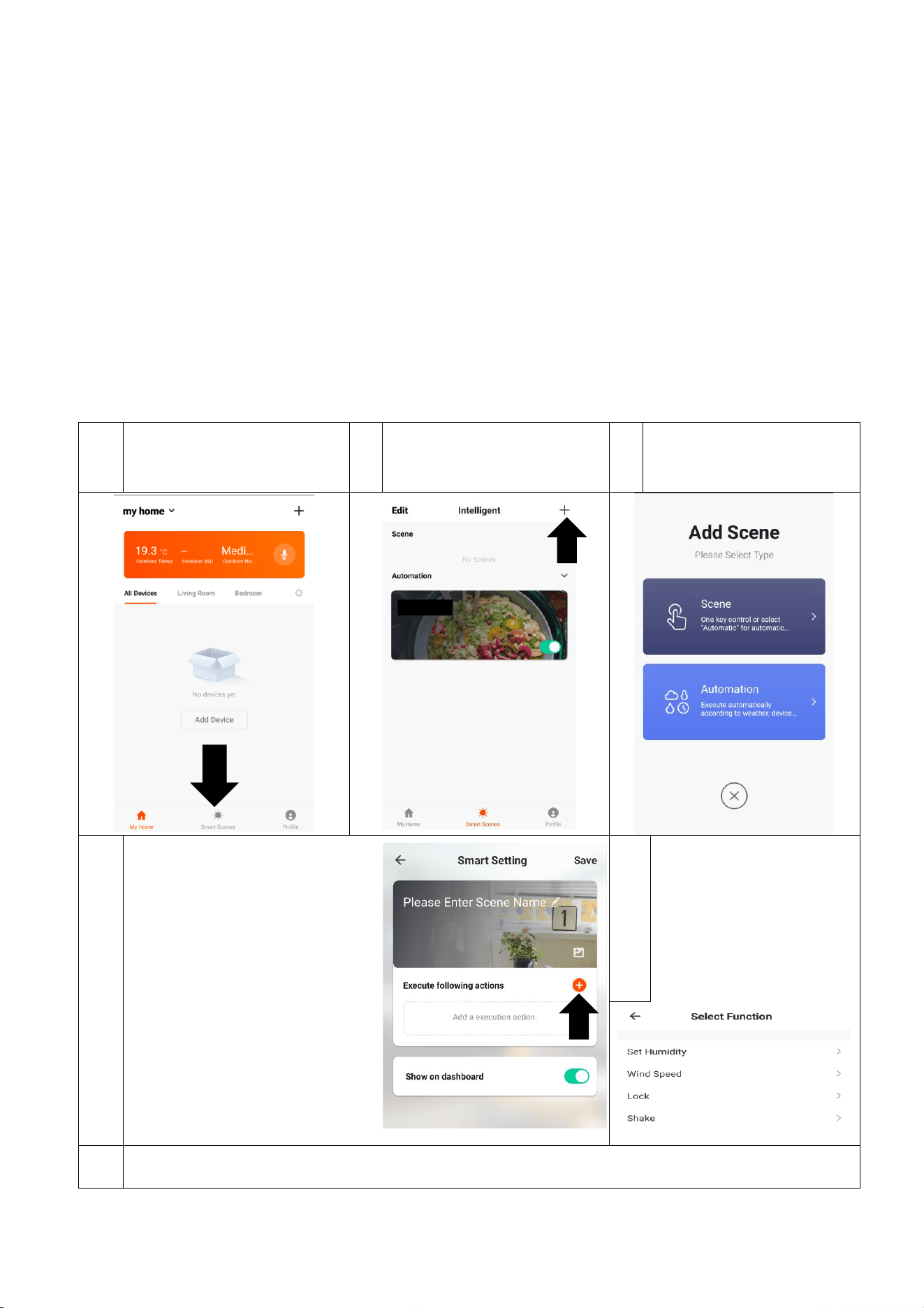
SMART SCENES
Smart Scenes is a powerful tool providing the option to customise the operation of the air
conditioner based both on conditions within the room and outside influences. This gives the
user the option of specifying much more intelligent actions. These are split into two categories
Scene and Automation.
SCENE
Scene allows for a one touch button to be added to the Home screen. The button can be used
to change a number of settings in one go, and can change all the settings within the unit. A
number of scenes can easily be setup, allowing the user to easily change between a number of
preset configurations.
Below is an example of how to set up a scene:
1
Press the Smart Scene tab at
the bottom of the Home
screen
2
Press the + in the top right
corner to add a smart scene.
3
Press Scene to create a
new Scene
4
Press the Pen next to Please
Enter Scene Name to input the
name for your Scene.
Show on Dashboard: Leave this
on if you require the scene to
be displayed as a button on
the Home Screen.
Press the Red Plus to add the
action required. Then select
the air conditioner from the list
of devices.
5
Choose the function, set
the value for the
function, and then press
the back button in the
top right corner, to
return to the previous
screen.
6
Once all the functions required have been added, press the Save button in the top right corner to
finalise and save your new Scene
USING THE WiFi APP
27
AUTOMATION
Automation allows an automatic action to be set up for the device. This can be triggered by the
Time, indoor temperature, humidity of the room, weather conditions, and a range of other
influences.
1
Press the Smart Scene tab at
the bottom of the Home
screen
2
Press the + in the top right
corner to add a smart scene.
3
Press Automation to
create a new Automation
scene
4
Setup is very similar to the scene
setup on the previous page, and
includes an extra section for
specifying a trigger for the scene to
start.
Press the Pen next to Please Enter
Scene Name to input the name for
your Scene
Press the Red + next to When any
condition is satisfied to add the
trigger
Press the Red + next to Execute
following actions to add the action
required. Then select the air
conditioner from the list of devices.
5
Select the condition
when the automation
should start. A number
of triggers can be
combined.
6
Chose the function, set
the value for the function,
and then press the back
button in the top right
corner, to return to the
previous screen.
7
Once all the functions required
have been added, press the
Save button in the top right
corner to finalise and save your
new scene.
The automation is now set up,
it can be turned on and off
using the toggle on the image
shown on step 2.
USING THE WiFi APP
28
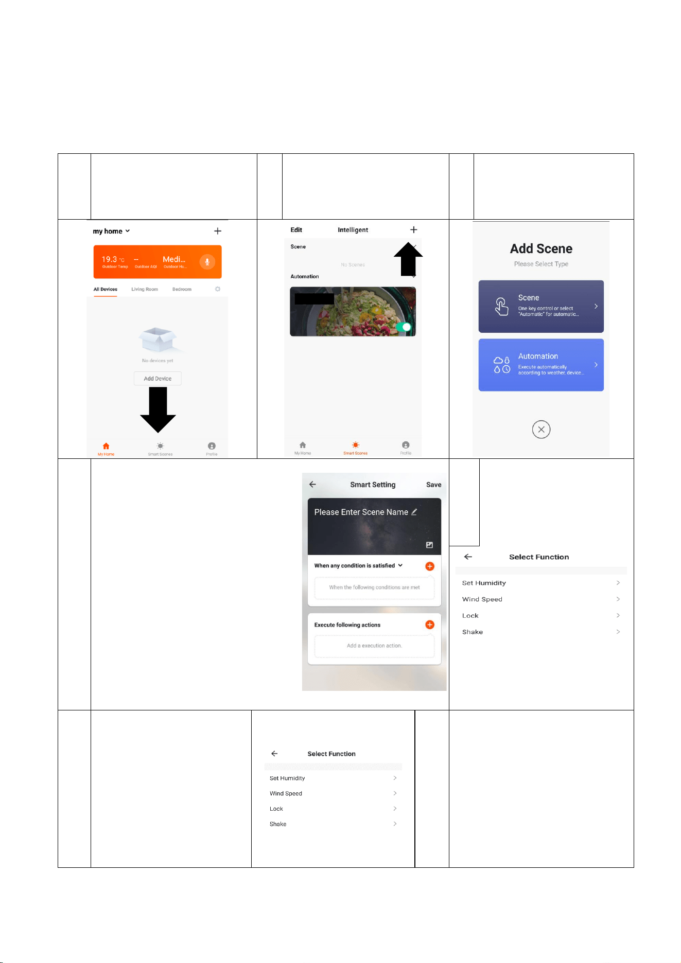
PROFILE TAB
The profile tab gives you the option to edit both your detail, and
use the added features of the unit, such as setting up room
management, where appliances can be grouped by rooms.
This will also show you the third party support offered on the
app, for linking the product up with Google Home and Amazon
Alexa.
DEVICE SETTINGS
When in the device screen further settings for the device can be
accessed, by pressing on the three dots in the top right hand
corner.
CHANGING THE NAME OF YOUR DEVICE
The top option within this allows you to change the name of the
device to something relevant to the use of the product, such as
“Living Room Air Conditioner”. Within the menu, you also have
the option of setting up a pattern lock or change your password.
SHARE DEVICE
This allows you to share access to the controls of your air
conditioner with friends and family.
THIRD PARTY CONTROL
This will take you through step by step how to connect the device
to your Amazon Alexa or Google Home device.
CLEANING AND MAINTENANCE
29
• Before cleaning, you must turn off the air conditioner and disconnect the power supply for at least
5 minutes.
• Under no circumstances should the air conditioner be flushed with water.
• Volatile liquid (e.g. thinner or gasoline) will damage the air conditioner, so only use soft dry cloth or
wet cloth dipped with neutral detergent to clean the air conditioner.
• Clean the filter screen regularly to avoid it clogging with dust, which will affect the airflow to the
unit. When the operating environment is dusty, the cleaning frequency should be increased
appropriately.
• After removing the filter screen, do not touch the fins of the indoor unit, as these can be sharp.
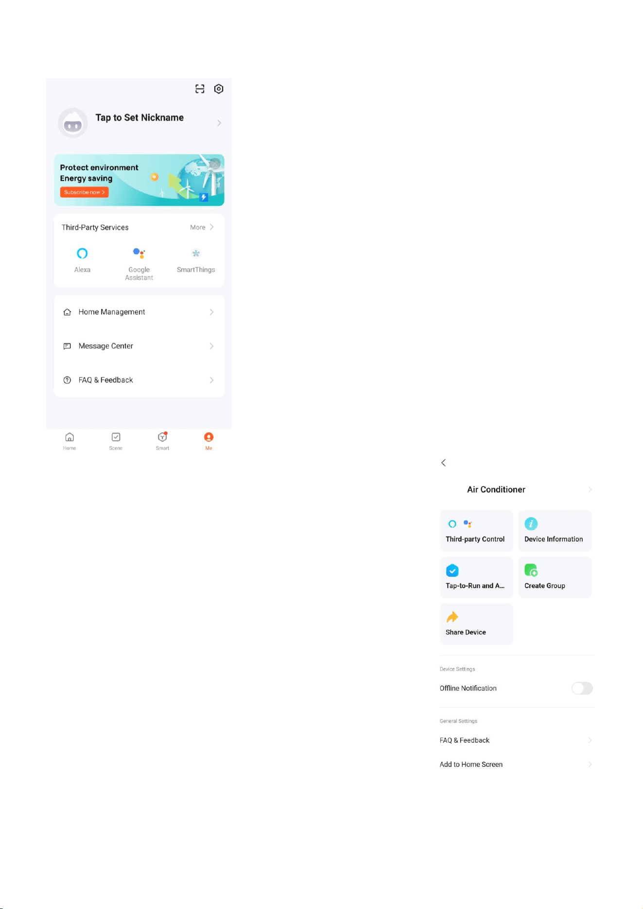
REMOVING THE GRILL
It is advisable to clean the air conditioner regularly to maintain its appearance and performance.
1. Push the two grill switched towards the centre to
unhook the grill before pulling the centre of the panel
downwards.
2. Care must be taken with the electrical
connectors (connecting the panel to
the main cassette) If necessery these
should be disconnected.
3. Hold the grill at a 45 angle to the unit
and lift to unhook from the rear of
the panel.
4. The filter can then be removed from the grill for cleaning.
CLEANING OF THE AIR FILTER
Following removal of the air filter following the steps above, it should be cleaned in
warm soapy water (<40°C).
<40
104
CLEANING AND MAINTENANCE
30
END OF SEASON MAINTENANCE
If the air conditioner is not going to be used for an extended period:
• Use the Self-Clean mode or set the air conditioner to fan mode on a slightly warm day so
that the inside of the appliance dries out.
• Switch off the power at the fuse box and remove the batteries from the remote control.
• Clean the filters.
START OF SEASON PREPARATION
If the air conditioner is to be used again after an extended period:
• Check that the air intake and exhaust openings of the interior and exterior units are not
blocked. Remove any dirt or debris that has accumulated.
• Check that the filter is installed within the indoor unit and is clean.
• Check that the condensation outlet drains properly and there is no dirt or organic blockage
(otherwise leakage may occur).
• Install 2 AAA batteries in the remote control.
• Turn the appliance on, set the time and desired setting.
REPLACING THE BATTERIES
• Remove the cover from the rear of the remote control.
• Replace the AAA batteries, ensuring the correct polarity.
• Reinstall the cover on the rear of the remote control.
• As soon as the batteries are inserted, press and hold the MODE
button on the remote until the correct icon is displayed:
COOLING ONLY
HEATING AND COOLING
TROUBLESHOOTING AND SELF DIAGNOSIS
31
MALFUNCTION
POSSIBLE CAUSE
The appliance
does not operate
Power failure
Damaged indoor/outdoor unit fan motor
Faulty compressor thermomagnetic circuit breaker
Faulty protective device or fuses
Loose connections
Self-protection in adverse conditions
Voltage higher / lower than the voltage range
Active TIMER-ON function
Damaged electronic control board
Strange odour
Air filter dirty
Noise of running
water
Back flow of liquid in the refrigerant circulation
A fine mist comes
from
the air outlet
This occurs when the air in the room becomes very cold, for example in
the COOLING or DEHUMIDIFYING modes.
A strange noise
can be heard
This noise is made by the expansion or contraction of the front panel due
to variations in temperature and does not indicate a problem.
Insufficient
airflow, either
hot or cold
Inappropriate temperature setting.
Air inlet or outlet of indoor or outdoor unit has been blocked.
Air filter is blocked.
Fan speed set at minimum.
Other sources of heat in the room.
No refrigerant.
The appliance
does not
respond to
commands
Remote control is not near enough to indoor unit.
Battery in Remote controller may have been exhausted.
Obstacles between remote control and signal receiver in indoor unit.
The display is off
DISPLAY button pressed on remote
Power failure
Remote cannot
select heating
mode.
Remove the batteries from the remote and follow the guide for setting
up the remote.
Switch off the air conditioner immediately and cut off the power supply in the event of:
Strange noises during operation.
Faulty electronic control board
Faulty fuses or switches.
Spraying water or objects inside the appliance.
Overheated cables.
Very strong smells coming from the appliance.
TROUBLESHOOTING AND SELF DIAGNOSIS
32
ERROR SIGNALS ON THE DISPLAY
In case of error, the display on the indoor unit shown the following error codes:
Error Code
Failure type
C5
Communication error between indoor unit and wired controller
E0
Indoor and outdoor communication failure
EC
Outdoor communication failure
E1
Indoor room temperature sensor
E2
Indoor coil temperature sensor
E3
Outdoor coil temperature sensor
E4
System abnormity
E5
Model configuration wrong
E6
Indoor fan motor fault
E7
Outdoor temperature sensor
E8
Exhaust temp. sensor
E9
IPM drive and module fault
EA
Current sensor fault
Ed
Indoor EEPROM fault
EC
Outdoor Communication fault
EE
Outdoor EEPROM fault
EF
Outdoor fan motor fault (DC motor)
EH
Outdoor suction temperature sensor fault
En
Outdoor gas pipe temperature sensor fault
EP
Temp. switch fault ( on top of the compressor)
EU
Voltage sensor fault
Ey
Outdoor liquid pipe temperature sensor fault
Protection Display Code List
H1
High pressure switch protection
H2
Low pressure switch protection
H6
Insufficient of refrigerant protection
HE
Phase sequence protection
PA
Indoor run mode conflict
P1
Overvoltage /lower voltage protection
P2
Overcurrent protection
P4
Exhaust over temperature protection
P5
Too cool protection in cooling mode
P6
Overheat protection in cooling mode
P7
Overheat protection in heating mode
P8
Outdoor over temperature
/ lower temperature protection
P9
Drive protection (software control )
P0
Module protection (hardware control)
PH
Exhaust temperature sensor failure protection of outdoor unit
PC
Coil temperature sensor failure protection of outdoor unit
TROUBLESHOOTING AND SELF DIAGNOSIS
33
OUTDOOR UNIT FAULT CODES
The outdoor unit has an LED on the power board. This LED will be illuminated when the
compressor is running and blink 1s on and 1s off when the compressor is in standby. If there is
a fault on the outdoor unit, it will blink on and off for half a second at a time, followed by a 3s
gap. The number of consecutive blinks will show the fault as per the table below:
No. of blinks
Fault
1
IPM protection
2
Over voltage /lower voltage
3
Overcurrent
4
Exhaust over temperature protection
5
Outdoor coil over temperature protection
6
Drive fault and protection (V1,VP1)
7
Communication fault with indoor unit
8
Compressor overheat fault (compressor top switch)
9
Short-circuit / open-circuit fault of outdoor temperature sensor
10
Short circuit / open-circuit fault of outdoor heat exchanger temperature
sensor
11
Short-circuit / open-circuit fault of exhaust temperature sensor
12
Voltage sensor fault
13
Current sensor fault
14
IPM fault
15
Communication fault between power source board and IPM
16
No feedback from DC fan motor(outdoor unit)
17
Defrost state
WIFI CONTROL TROUBLESHOOTING
Description
Possible Cause
Air conditioner can’t
be configured
successfully
1. Check the mobile device is connected to WIFI
2. Check the AC is connected
3. Check that any firewall or other restrictions are causing problems
4. Check the router is functioning normally
5. Check that the router isn’t blocking the App
Mobile device can’t
control the air
conditioner
The app displays “Identification failed”. This indicates that the AC has been
reset and the mobile device has lost contact with the AC. Reconnect the
device following the above instructions. If this fails, delete the AC from your
devices list and start the install process from the beginning.
Mobile device can’t
find AC
The app displays “Air conditioner out of line”. Check the below:
1. The AC has been reconfigured
2. The AC is not receiving power
3. The router is not powered on
4. The AC can’t connect to router
5. The AC can’t connect to network through the router
6. The mobile device can’t connect to the router
7. The mobile device can’t connect to a network (when being used
remotely)
TECHNICAL SPECIFICATION
34
Model
iQool-SRC18HP
iQool-SRC24HP
Rated voltage and frequency (Ph-V-Hz)
220-240V~/50HZ
220-240V~/50HZ
Fuse Required
16A
20A
Mode
Cooling
Heating
Cooling
Heating
Rated capacity (W)
5300
(620~5580)
5800
(760~6100)
7030
(2200~7500)
7900
(2320~8350)
Power input - outdoor (W)
1625
(395~2750)
1620
(350~2400)
2390
(710~3165)
2330
(745~2965)
Current input - Outdoor (A)
7.5
(1.8~12.0)
7.1
(1.6~11)
10.2
(3.8~14)
8.5
(4.0~13)
SEER/SCOP(W/W)
6.3 (A++)
4.0 (A+)
6.2 (A++)
4.0 (A+)
Nominal load (kW)
5.3
4.3
7.03
5.5
Balance point temperature heating (
o
C)
/
-10
/
-10
Min. outdoor operating temperature (
o
C)
-15
-15
-15
-15
Thermostat-off mode (W)
5
13.6
Standby mode (W)
2.5
2.5
Off mode (W)
2.5
2.5
Annual consumption (kW)
294
1505
402
2075
Copper Pipe Type length
5m
5m
Liquid side / Gas side (mm/inch)
6.35 (1/4”) + 9.52 (3/8”)
6.35 (1/4”) + 12.7 (1/2”)
Max. refrigerant pipe length for each unit
30m
30m
Max. elevation
15m
15m
Interconnecting Cable
5×1.5mm²
5×1.5mm²
Moisture Removal (L/h)
1.5
2.0
Indoor
Air Flow (m
3
/h)
1220
1500
Dimensions (L*W*H) (mm)
Cassette: 840×840×245 / Panel: 950x950x45
Packaging (L*W*H (mm)
Cassette: 935×935×305 / Panel: 1055x1055x90
Net / Gross weight (Kg)
Cassette: 23/27 / Panel: 6/9
Cassette: 24/28 / Panel: 6/9
Noise – Sound pressure level (dB/A)
42
46
Noise – Sound power level (dB/A)
52
56
Outdoor
Dimension (L*W*H) (mm)
780×605×307
845×700×342
Packaging (L*W*H) (mm)
890×648×385
960×430×755
Net / Gross Weight (Kg)
30/33
40/44
Noise – Sound pressure level (dB/A)
52
54
Noise – Sound power level (dB/A)
62
64
Refrigerant type/weight
R32 / 0.95kg
R32 / 1.35Kg
CO2 equivalent (T)
0.642
0.911
Defrost mode
Automatic defrosting
Automatic defrosting
Applicable climate types
Cooling:-15-52/Heating:-15-24
Cooling:-15-52/Heating:-15-24
Due to continuous product development process
specification may change
TECHNICAL SPECIFICATION
35
Model
iQool-SRC36HP
Rated voltage and frequency (Ph-V-Hz)
220-240V~/50HZ
Fuse Required
25A
Mode
Cooling
Heating
Rated capacity (W)
10550
(3080~12300)
11720
(3280~13500)
Power input - Outdoor (W)
3180
(210~4460)
3280
(300~3560)
Current input - Outdoor (A)
14.6
(1.0~20.3)
15.0
(1.4~16.3)
SEER/SCOP(W/W)
6.2 (A++)
4.1 (A+)
Nominal load (kW)
10.5
8.5
Balance point temperature heating (
o
C)
/
-10
Min. outdoor operating temperature (
o
C)
-15
-15
Thermostat-off mode (W)
21
Standby mode (W)
15
Off mode (W)
15
Annual consumption (kW)
596
2902
Copper Pipe Type length
5m
Liquid side / Gas side (mm/inch)
9.52 (3/8”) + 15.9 (5/8”) +
Max. refrigerant pipe length for each unit
50m
Max. elevation
25m
Interconnecting Cable
3×1.5mm² and 3×0.75mm²
Moisture Removal (L/h)
3.6
Indoor
Air Flow (m
3
/h)
1900
Dimensions (L*W*H) (mm)
Cassette: 840×840×290 / Panel: 950x950x45
Packaging (L*W*H (mm)
Cassette: 935×935×305 / Panel: 1055x1055x90
Net / Gross weight (Kg)
Cassette: 26/31 / Panel: 6/9
Noise – Sound pressure level (dB/A)
50
Noise – Sound power level (dB/A)
60
Outdoor
Dimension (L*W*H) (mm)
910×804×378
Packaging (L*W*H) (mm)
1022x860x480
Net / Gross Weight (Kg)
55/60
Noise – Sound pressure level (dB/A)
57
Noise – Sound power level (dB/A)
67
Refrigerant type/weight
R32 / 2.1Kg
CO2 equivalent (T)
1.418
Defrost mode
Automatic defrosting
Applicable climate types
Cooling:-15-52/Heating:-15-24
Due to continuous product development process
specification may change
SUPPORT
36
electriQ UK SUPPORT
Please, for your own convenience, check the troubleshooting guide before calling the service line.
0330 390 3061
Office hours: 9AM - 5PM Monday to Friday
www.electriQ.co.uk
Unit 2A, Trident Business Park,
Neptune Way, Leeds Road, Huddersfield, HD2 1UA
EU DECLARATION OF CONFORMITY
Hereby, electriQ declares that these air conditioners are in compliance with Directive
2014/53/EU. The full text of the EU declaration of conformity is available at the following
internet addresses:
https://www.electriq.co.uk/DOC/EU/iQool-SRC18HP.pdf
https://www.electriq.co.uk/DOC/EU/iQool-SRC24HP.pdf
https://www.electriq.co.uk/DOC/EU/iQool-SRC36HP.pdf
UK DECLARATION OF CONFORMITY
Hereby, electriQ declares that these air conditioners are in compliance with Radio Equipment
Regulations 2017. The full text of the UK declaration of conformity is available at the
following internet addresses:
https://www.electriq.co.uk/DOC/UK/iQool-SRC18HP.pdf
https://www.electriq.co.uk/DOC/UK/iQool-SRC24HP.pdf
https://www.electriq.co.uk/DOC/UK/iQool-SRC36HP.pdf
Disposal: Do not dispose this product as unsorted municipal waste. Collection of such
waste must be handled separately as special treatment is necessary.
Recycling facilities are now available for all customers at which you can deposit your
old electrical products. Customers will be able to take any old electrical equipment to
participating sites run by their local councils. Please remember that this equipment
will be further handled during the recycling process, so please be considerate when
depositing your equipment. Please contact the local council for details of your local
household waste recycling centres.
SUPPORT
37
WARRANTY INFORMATION
electriQ guarantee provides cover against material or manufacturing faults. This means
that if your air conditioner develops a fault within the first 2 years, we will arrange for it
to be repaired or replaced*. We will also provide replacement parts within the first 5
years.
The system must be installed and annually serviced by an F-gas registered engineer.
Evidence of this must be provided when the fault is logged with our technical team. Faults
arising from installation errors and/or damage are specifically excluded.
Where we are unable to confirm that a fault is related to a manufacturing fault, we reserve
the right to make a charge to cover the costs of an engineer visit to assess and repair the
unit. This charge will be refunded in full if the fault is confirmed to be due to a
manufacturing fault.
This unit must be operated under conditions as recommended in this user manual, at
voltages indicated on the unit. Any attempts made to service or modify the unit by
unqualified person, will render this WARRANTY VOID.
This warranty is in addition to, and does not affect, your statutory rights.
* A replacement may be offered where electriQ deem a repair not to be viable.
We recommend that you note the details of your purchase below and retain your original proof of
purchase receipt with this manual. Keep these documents safe in the event of a warranty claim.
Purchase Date:
Retailer name:
Model number:
Serial number:
Installation Date:
Installer name:
Engineer/ Company name:
Engineers Registration Number
Service Dates
V20240408