
A18CS57
Original instructions
2
2
I
mportant!
It is essential that you read the instructions in this manual before
assembling, operating, and maintaining the product.
Subject to technical modifications.
3
3
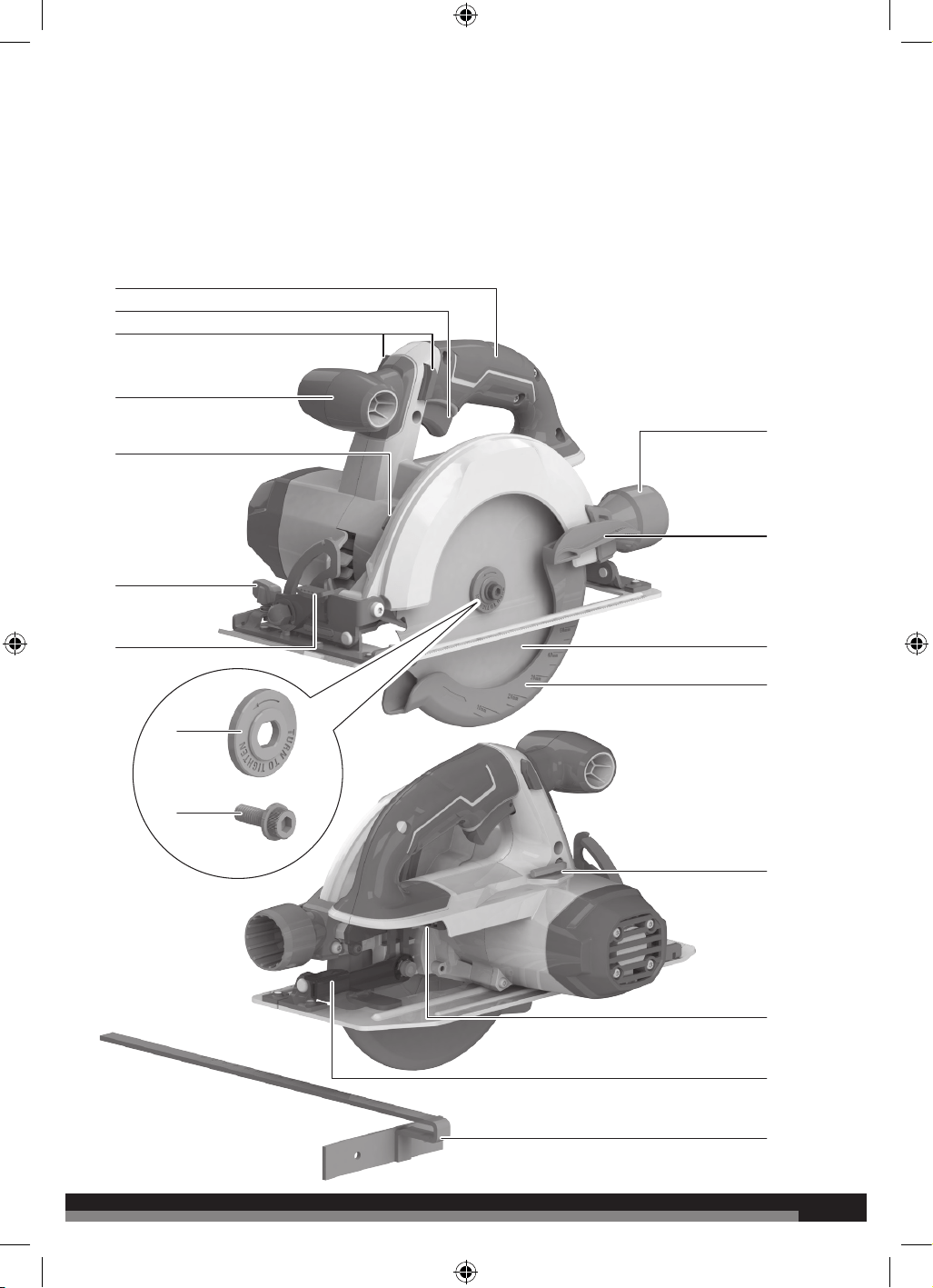
1. Handle, insulated gripping surface
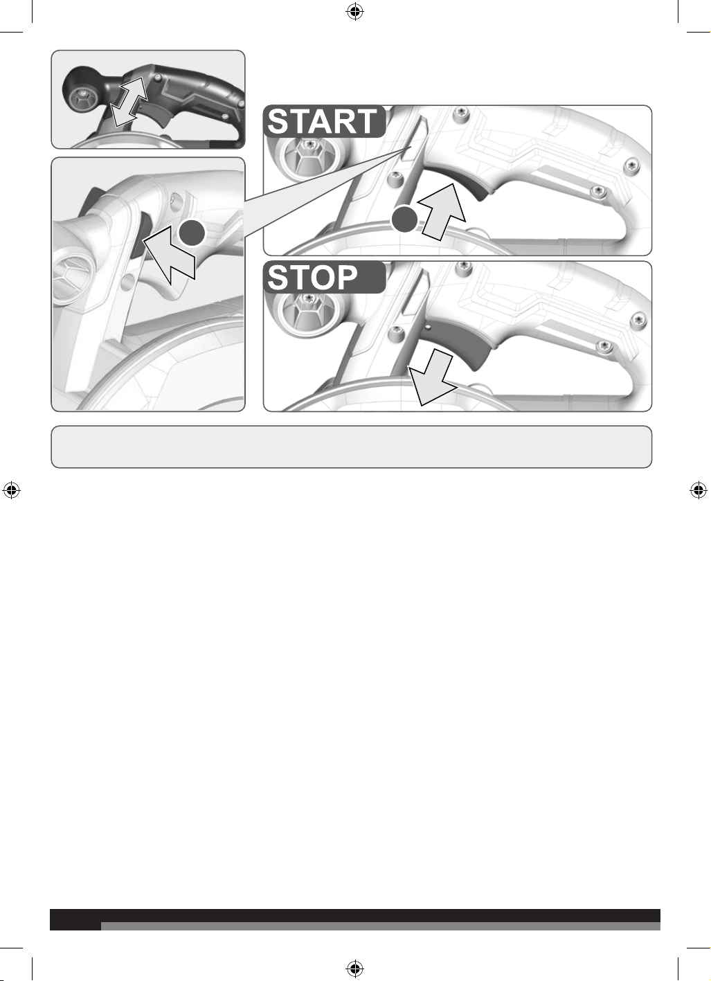
2. Switch trigger
3. Lock-off button
4. Front handle
5. Spindle lock button
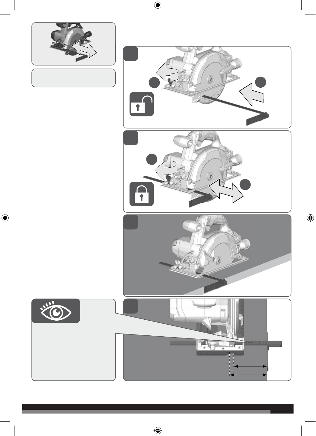
6. Edge guide knob
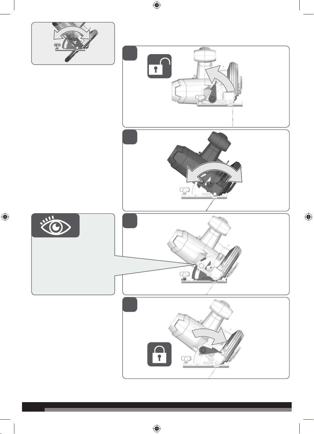
7. Bevel adjustment lever
8. Outer flange
9. Blade screw
10. Dust pipe joint
11. Lower blade guard lever
12. Blade
13. Lower blade guard
14. Hex key
15. Battery port
16. Depth adjustment lock lever
17. Edge guide fence
15
16
10
11
12
13
14
17
5
4
6
7
1
2
3
8
9
4
4
14
18
06
07
08
09
15
12
90°
16
17
13
19
10
11
5
5
14
18
06
07
08
09
15
12
90°
16
17
13
19
10
11
6
6
1
2
1
2
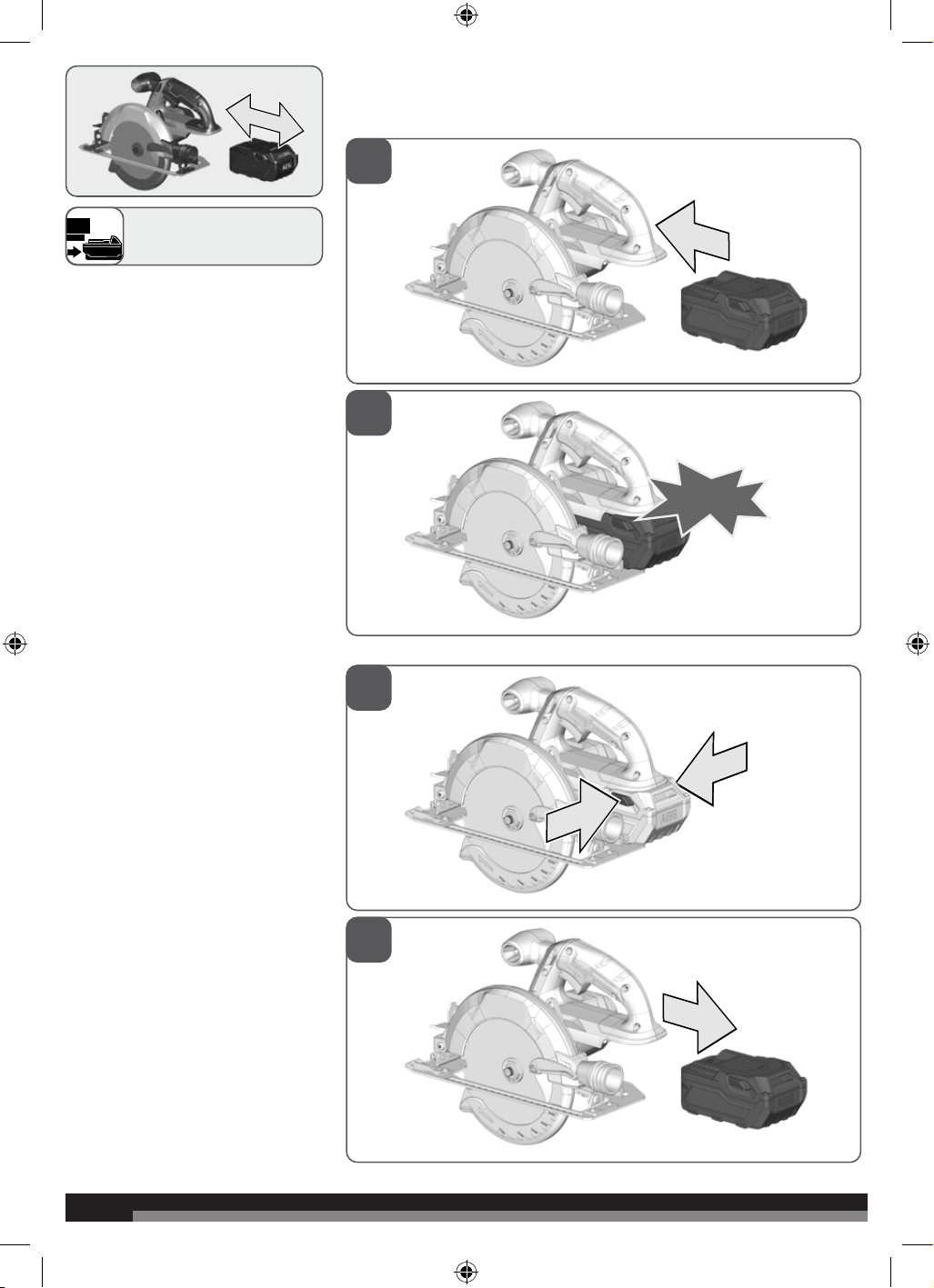
click
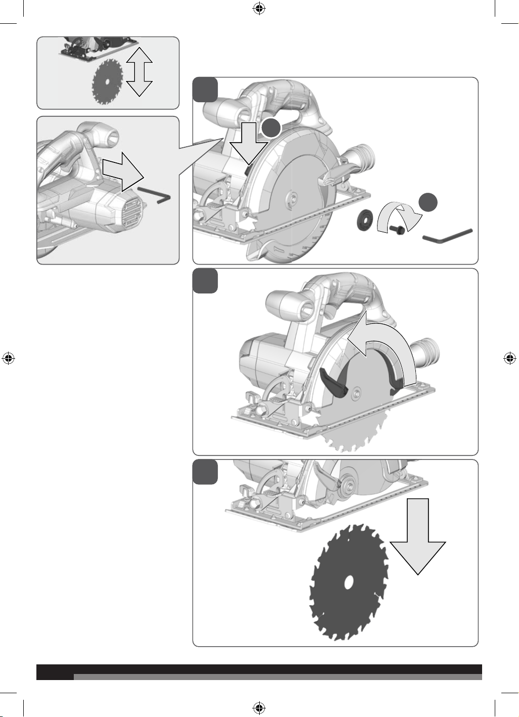
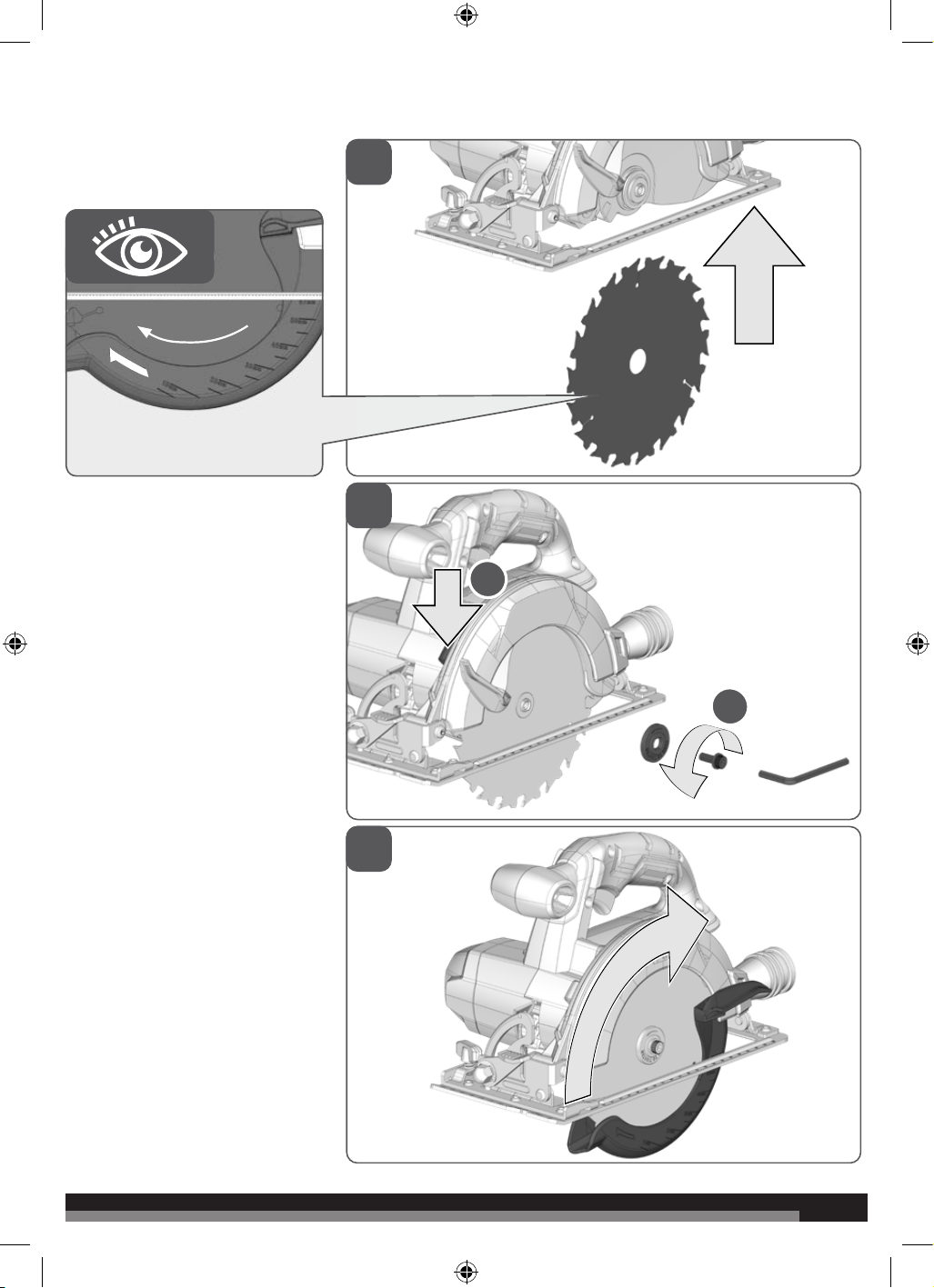
Remove the battery pack
before starting any work on
the machine.
7
7
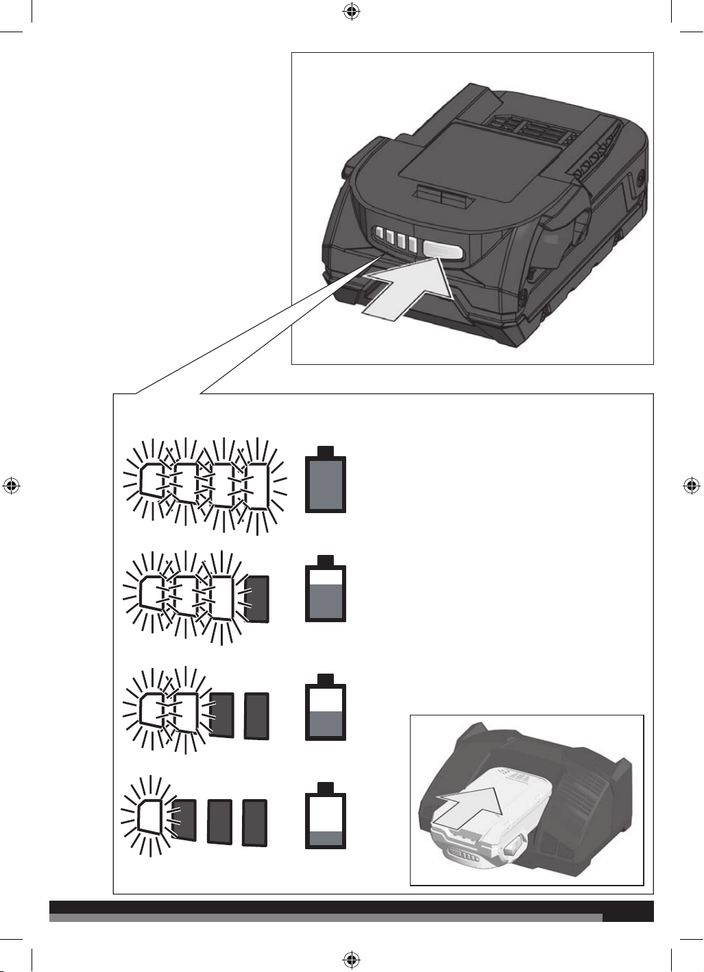
75-100 %
50-75 %
25-50 %
0-25 %
8
8
1
2
3
1
2
9
9
2
1
2
3
1
2
10
10
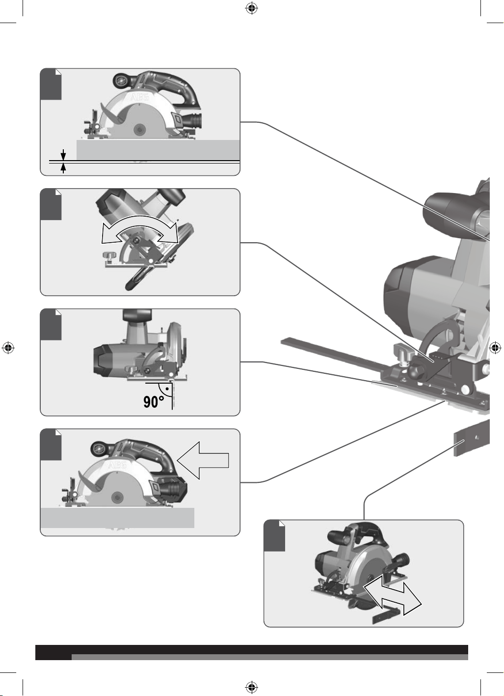
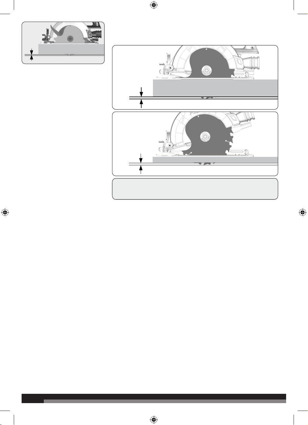
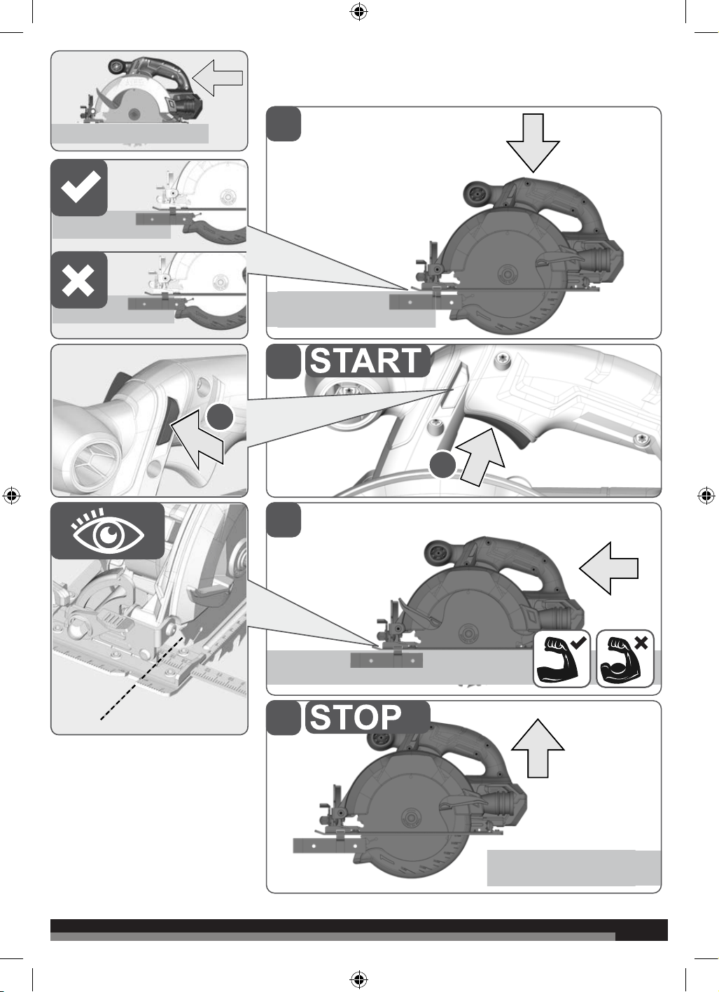
Adjust the cutting depth to the thickness of the workpiece. Less than a full tooth
of the blade teeth should be visible below the workpiece.
11
11
1
2
3
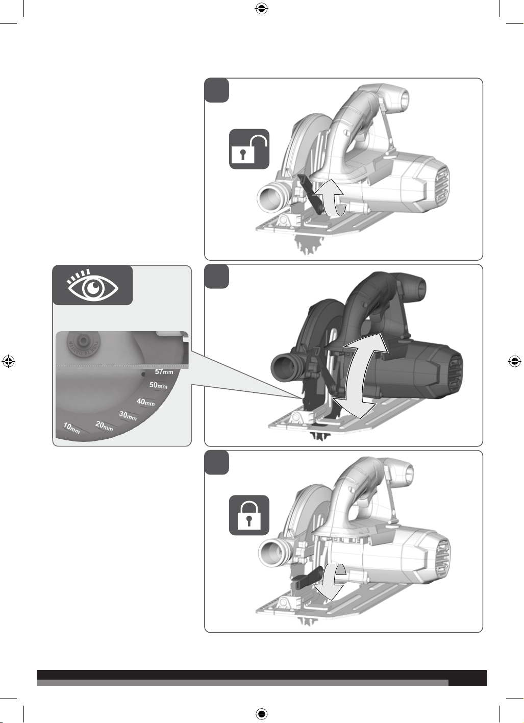
0 - 57 mm
12
12
1
2
3
4
0° - 50°
13
13
1
2
0°45°
x mm
y mm
3
4
0 - 13 cm
2
2
1
1
Carry out a test cut
14
14
2
1
For safety reasons this power tool is fitted with a switch lock and the On-/Off switch cannot be locked in the „On“ position.
15
15
3
1
45°
0°
2
4
2
1
16
16
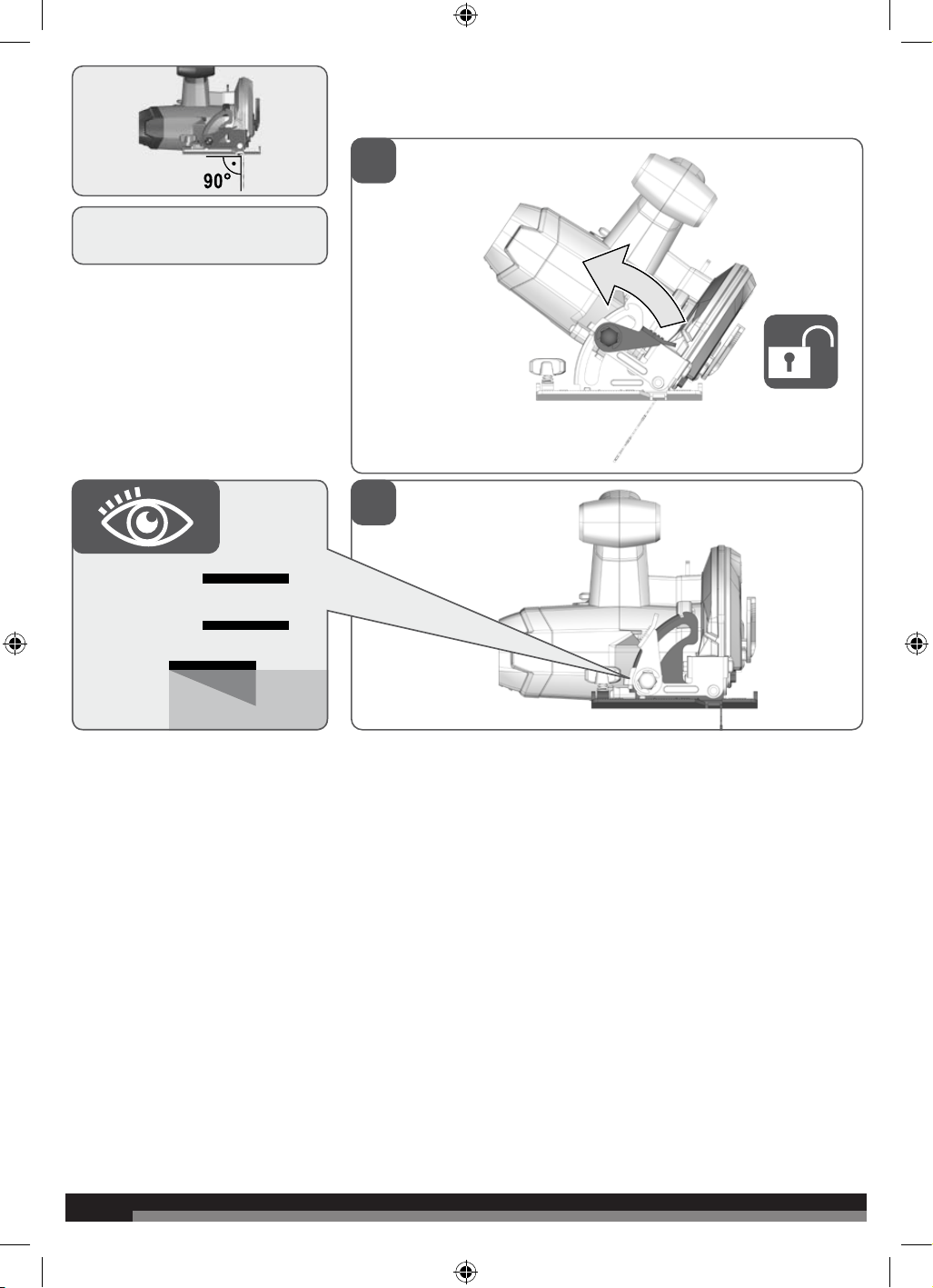
90°
-
If a correction of the 90° angle of the
guide-plate to the saw blade is
necessary, use the correction screw.
1
2
0°

17
17
3
4
90°
18
18
2
1
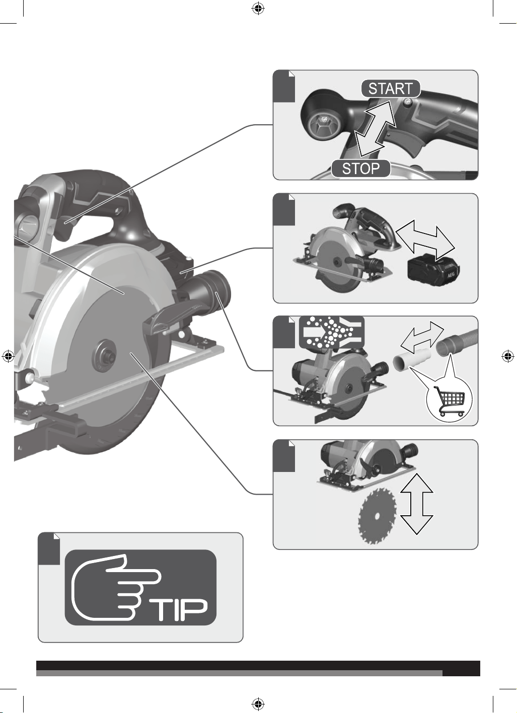
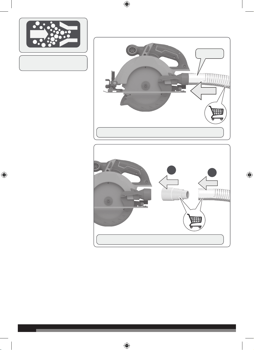
Accessory can be attached to a dust
extraction unit.
Always connect the dust pipe joint to the circular saw before using.
ø 30 mm
Always connect the vacuum attachment to a standard vacuum hose.
19
19
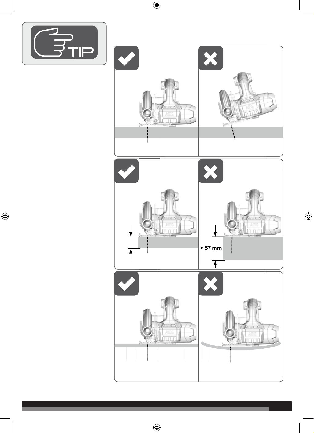
1
max.
57 mm
> 57 mm
20
20
BATTERY AND CHARGER
Compatible battery pack
(not included)
Compatible charger
(not included)
L1815R
L1820R
L1825R
L1830R
L1830R-X5
L1840R
L1850R
L1860R
L1860R-X5
L1890R
L1820S
AL18G
AL1218G
BL1218
BLK1218
BL18DP-X5
BL18DP2-X5
BL18DPS
Use AEG 18V battery and charger only
WARNING!
WARNING! Read all safety warnings, instructions, illustrations
and specifications provided with this power tool. Failure to follow
all instructions listed below may result in electric shock, fire and/
or serious injury. Save all warnings and instructions for future
reference.
CIRCULAR SAW SAFETY WARNINGS
CUTTING PROCEDURES
Danger: Keep hands away from cutting area and the blade.
Keep your second hand on auxiliary handle, or motor housing. If
both hands are holding the saw, they cannot be cut by the blade.
Do not reach underneath the workpiece. The guard cannot protect
you from the blade below the workpiece.
Adjust the cutting depth to the thickness of the workpiece.
Less than a full tooth of the blade teeth should be visible below the
workpiece.
Never hold the workpiece in your hands or across your leg while
cutting. Secure the workpiece to a stable platform. It is important
to support the work properly to minimize body exposure, blade
binding, or loss of control.
Hold the power tool by insulated gripping surfaces, when
performing an operation where the cutting tool may contact
hidden wiring. Contact with a “live” wire will also make exposed metal
parts of the power tool “live” and could give the operator an electric
shock.
When ripping, always use a rip fence or straight edge guide.
This improves the accuracy of cut and reduces the chance of blade
binding.
Always use blades with correct size and shape (diamond versus
round) of arbour holes. Blades that do not match the mounting
hardware of the saw will run eccentrically, causing loss of control.
Never use damaged or incorrect blade washers or bolt. The blade
washers and bolt were specially designed for your saw, for optimum
performance and safety of operation.
KICKBACK CAUSES AND RELATED WARNINGS
– kickback is a sudden reaction to a pinched, jammed or
misaligned saw blade, causing an uncontrolled saw to lift up
and out of the workpiece toward the operator;
– when the blade is pinched or jammed tightly by the kerf
TECHNICAL DATA CIRCULAR SAW
A18CS57
Rated voltage 18 V
No-load speed 3700 min
-1
Saw blade dia. x hole dia 165 x 20 mm
Cutting depth at 0° 57 mm
Cutting depth at 45° 39.7 mm
Cutting depth at 45° 36.7 mm
Blade thickness 1.6 mm
Blade teeth 18
Weight - not including battery pack 3.0 kg
Measured values determined according to EN 62841:
A-weighted sound pressure level L
pA
= 88.5 dB(A)
Uncertainty K 3 dB(A)
A-weighted sound power level L
WA
= 99.5 dB(A)
Uncertainty K 3 dB(A)
Wear ear protectors.
The vibration total values (triaxial vector sum) determined according to EN 62841:
Vibration emission value a
h
= 1.7 m/s
2
Uncertainty K 1.5 m/s
2
WARNING
The vibration emission level given in this information sheet has been measured in accordance with a standardised test given in EN 62841 and
may be used to compare one tool with another. It may be used for a preliminary assessment of exposure. The declared vibration emission level
represents the main applications of the tool. However if the tool is used for dierent applications, with dierent accessories or poorly maintained,
the vibration emission may dier. This may significantly increase the exposure level over the total working period.
An estimation of the level of exposure to vibration should also take into account the times when the tool is switched o or when it is running but
not actually doing the job. This may significantly reduce the exposure level over the total working period.
Identify additional safety measures to protect the operator from the eects of vibration such as: maintain the tool and the accessories, keep the
hands warm, organisation of work patterns.
21
21
closing down, the blade stalls and the motor reaction drives
the unit rapidly back toward the operator;
– if the blade becomes twisted or misaligned in the cut, the
teeth at the back edge of the blade can dig into the top
surface of the wood causing the blade to climb out of the kerf
and jump back toward the operator.
Kickback is the result of saw misuse and/or incorrect operating
procedures or conditions and can be avoided by taking proper
precautions as given below.
Maintain a firm grip with both hands on the saw and position
your arms to resist kickback forces. Position your body to either
side of the blade, but not in line with the blade.
Kickback could cause the saw to jump backwards, but kickback forces
can be controlled by the operator, if proper precautions are taken.
When blade is binding, or when interrupting a cut for any reason,
release the trigger and hold the saw motionless in the material
until the blade comes to a complete stop. Never attempt to
remove the saw from the work or pull the saw backward while
the blade is in motion or kickback may occur. Investigate and take
corrective actions to eliminate the cause of blade binding.
When restarting a saw in the workpiece, centre the saw blade in
the kerf so that the saw teeth are not engaged into the material.
If a saw blade binds, it may walk up or kickback from the workpiece
as the saw is restarted.
Support large panels to minimise the risk of blade pinching and
kickback. Large panels tend to sag under their own weight. Supports
must be placed under the panel on both sides, near the line of cut and
near the edge of the panel.
Do not use dull or damaged blades. Unsharpened or improperly set
blades produce narrow kerf causing excessive friction, blade binding
and kickback.
Blade depth and bevel adjusting locking levers must be tight and
secure before making cut. If blade adjustment shifts while cutting, it
may cause binding and kickback.
Use extra caution when sawing into existing walls or other blind
areas. The protruding blade may cut objects that can cause kickback.
LOWER GUARD FUNCTION
Check lower guard for proper closing before each use. Do not
operate the saw if lower guard does not move freely and close
instantly. Never clamp or tie the lower guard into the open
position. If saw is accidentally dropped, lower guard may be bent.
Raise the lower guard with the retracting handle and make sure it
moves freely and does not touch the blade or any other part, in all
angles and depths of cut.
Check the operation of the lower guard spring. If the guard and
the spring are not operating properly, they must be serviced
before use. Lower guard may operate sluggishly due to damaged
parts, gummy deposits, or a build-up of debris.
The lower guard may be retracted manually only for special cuts
such as “plunge cuts” and “compound cuts”. Raise the lower
guard by the retracting handle and as soon as the blade enters
the material, the lower guard must be released. For all other
sawing, the lower guard should operate automatically.
Always observe that the lower guard is covering the blade before
placing saw down on bench or floor. An unprotected, coasting
blade will cause the saw to walk backwards, cutting whatever is in its
path. Be aware of the time it takes for the blade to stop after switch
is released.
ADDITIONAL SAFETY AND WORKING INSTRUCTIONS
Wear ear protectors. Exposure to noise can cause hearing loss.
Always wear goggles when using the machine. It is recommended to
wear gloves, sturdy non slipping shoes and apron.
The dust produced when using this tool may be harmful to health. Do
not inhale the dust.
Dust may enter the eyes or respiratory system. Wear eye protection at
all times. Wear appropriate dust control mask with filters suitable for
protecting against particles from the material being cut. Do not eat,
drink, or smoke in the work area. Ensure adequate ventilation.
The blades are very sharp and will become hot during use. Wear
gloves when changing blades. Keep hands away from the cutting area
at all times. Never hold workpiece being cut in your hands or across
your leg. Clamp the workpiece whenever possible.
Injuries may be caused or aggravated by prolonged use of a tool.
When using any tool for prolonged periods, ensure you take regular
breaks.
Do not use saw blades not corresponding to the key data given in
these instructions for use.
Use only blade diameter(s) in accordance with the markings.
Do not use any abrasive wheels.
Identify the correct saw blade to be used for the material to be cut.
Use only saw blades that are marked with a speed equal or higher
than the speed marked on the tool.
Use only saw blades recommended by the manufacturer, which
conform to EN 847-1, if intended for wood and analogous materials.
Avoid overheating the blade tips and melting the plastic.
Wear a dust mask.
Do not fix the on/o switch in the “on” position when using the saw
hand-held.
Manually retract the lower guard by
Raise the lower guard by the retracting handle and ensure that the
lower guard returns to the original position. If the lower guard does
not function properly. Stop using the product and have it repaired.
Ambient temperature range for tool during operation is between 0°C
and 40°C.
Ambient temperature range for tool storage is between 0°C and 40°C.
The recommended ambient temperature range for the charging
system during charging is between 10°C and 38°C.
ADDITIONAL BATTERY SAFETY WARNINGS
WARNING! To reduce the risk of fire, personal injury, and product
damage due to a short circuit, never immerse or expose your tool,
battery pack or charger in fluid or allow a fluid to flow inside them.
Corrosive or conductive fluids, such as seawater, certain industrial
chemicals, and bleach or bleach containing products, etc., can cause
a short circuit.
Ambient temperature range for battery during use is between 0°C
and 40°C.
Ambient temperature range for battery storage is between 0°C and
20°C.
SPECIFIED CONDITIONS OF USE
The product is designed for rip- and cross-cutting of wood or similar
materials up to a maximum depth of 57 mm. The product can make
straight or bevelled cuts between 0 and 50 degrees. The product is
to be used with the base of the tool in contact with the workpiece. It
should only be used in a dry, well lit and well ventilated area.
The product is designed for handheld use. The product is not to be
mounted onto a workbench. Do not use for cutting metal or masonry.
Do not use the product for any other purpose. Use of the product
for operations dierent from intended could result in a hazardous
situation.
BATTERIES
Battery packs which have not been used for some time should be
recharged before use.
Temperatures in excess of 50°C (122°F) reduce the performance of
the battery pack. Avoid extended exposure to heat or sunshine (risk
of overheating).
22
22
The contacts of chargers and battery packs must be kept clean.
For an optimum life-time, the battery packs have to be fully charged,
after used.
To obtain the longest possible battery life remove the battery pack
from the charger once it is fully charged.
For battery pack storage longer than 30 days:
• Store the battery pack where the temperature is below 27°C and
away from moisture.
• Store the battery packs in a 30% - 50% charged condition.
• Every six months of storage, charge the pack as normal.
TRANSPORTING LITHIUM BATTERIES
Lithium-ion batteries are subject to the Dangerous Goods Legislation
requirements.
Transportation of those batteries has to be done in accordance with
local, national and international provisions and regulations.
■ The user can transport the batteries by road without further
requirements.
■ Commercial transport of Lithium-Ion batteries by third parties is
subject to Dangerous Goods regulations. Transport preparation
and transport are exclusively to be carried out by appropriately
trained persons and the process has to be accompanied by
corresponding experts.
When transporting batteries:
■ Ensure that battery contact terminals are protected and insulated
to prevent short circuit.
■ Ensure that battery pack is secured against movement within
packaging.
■ Do not transport batteries that are cracked or leak.
Check with forwarding company for further advice
BATTERY PACK PROTECTION LI-ION BATTERY
The battery pack has overload protection that protects it from being
overloaded and helps to ensure long life. Under extreme stress the
battery electronics switch o the machine automatically. To restart,
switch the machine o and then on again. If the machine does not
start up again, the battery pack may have discharged completely. In
this case it must be recharged in the battery charger.
MAINTENANCE
Clean the product and guarding system with clean cloths or brushes.
The ventilation slots of the machine must be kept clear at all times.
Use only AEG accessories and AEG spare parts. Should components
need to be replaced which have not been described, please contact
one of our AEG service agents (see our list of guarantee/service
addresses).
If needed, an exploded view of the tool can be ordered. Please state
the Article No. as well as the machine type printed on the label and
order the drawing at your local service agents or directly at:
Techtronic Industries Australia Pty Ltd
PO Box 1065
Mount Waverley VIC 3149
Tel. no. 1300 234 797
Australia
Techtronic Industries N.Z. Limited
PO Box 12-806
Penrose AUCKLAND 1642
Tel. no. 0800 234 797(0800 AEGPWR)
New Zealand
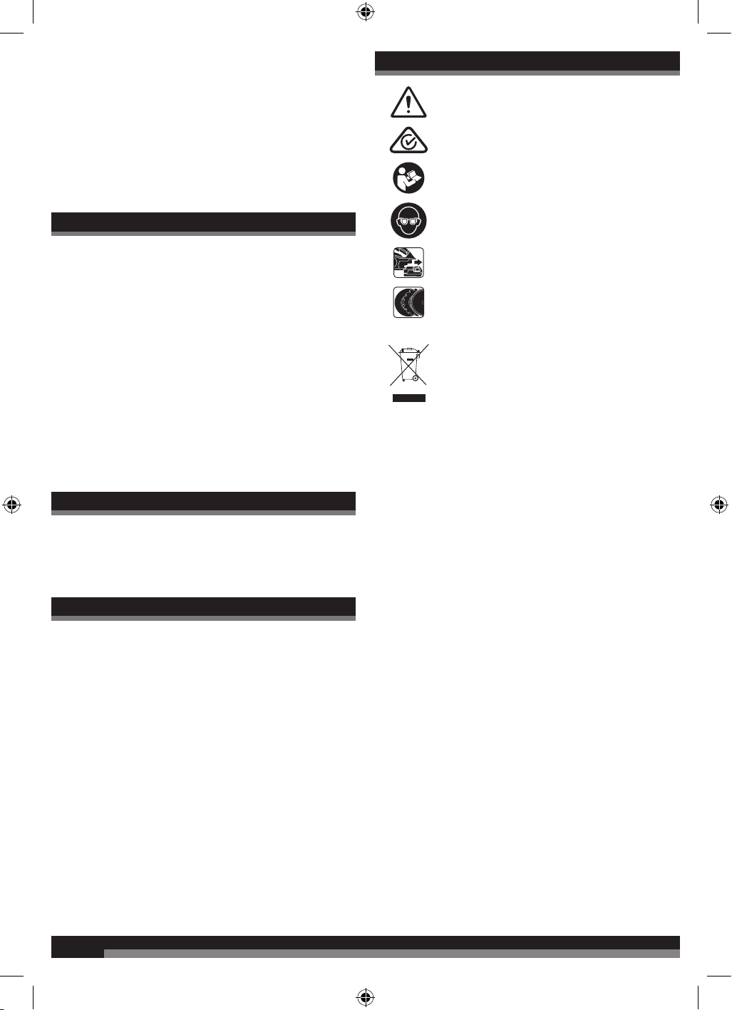
SYMBOLS
Safety alert
Regulatory Compliance Mark (RCM). Product meets
applicable regulatory requirements.
Please read the instructions carefully before starting
the product.
Always wear goggles when using the product.
Remove the battery pack before starting any work
on the product.
Accessory - Not included in standard equipment,
available as an accessory.
Do not dispose of electric tools together with
household waste material! In observance of
European Directive 2002/96/EC on waste electrical
and electronic equipment and its implementation
in accordance with national law, electric tools that
have reached the end of their life must be collected
separately and returned to an environmentally
compatible recycling facility.

Techtronic Industries Australia Pty Ltd
31 Gilby Road, Mount Waverley,
VIC, 3149, Australia
Techtronic Industries N.Z. Limited
Unit C, 70 Business Parade South,
Highbrook, Auckland 2013, New Zealand
www.aegpowertools.com.au
www.aegpowertools.co.nz
AEG is a registered trade mark used under
license from AB Electrolux (publ)
© 2021 Techtronic Cordless GP. 961096744-01A