EN Installation Instructions
STU1822

Contents
1. IMPORTANT SAFETY INSTRUCTIONS 1
2. TOOLS WHICH MAY BE NEEDED 4
3. MATERIALS WHICH MAY BE NEEDED 4
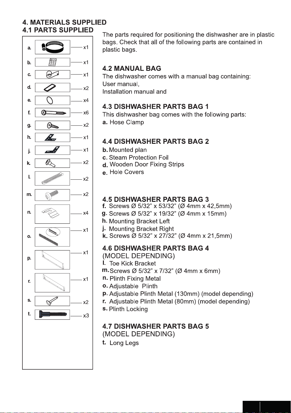
4. MATERIALS SUPPLIED 5
4.1 PARTS SUPPLIED 5
4.2 MANUAL BAG 5
4.3 DISHWASHER PARTS BAG 1 5
4.4 DISHWASHER PARTS BAG 2 5
4.5 DISHWASHER PARTS BAG 3 5
4.6 DISHWASHER PARTS BAG 4 5
4.7 DISHWASHER PARTS BAG 5 5
5. DISHWASHER SPECIFICATIONS 6
5.1 TECHNICAL FEATURES 6
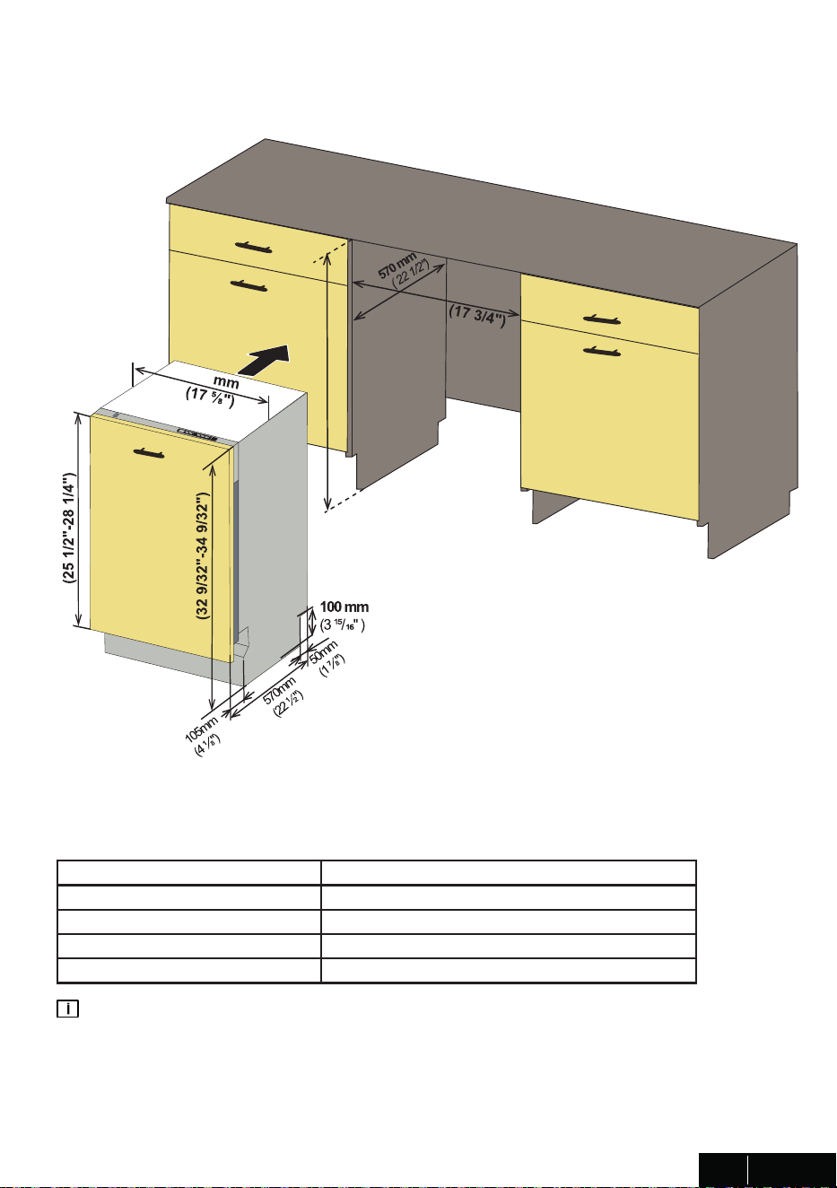
6. ENCLOSURE PREPARATION 7
6.1 ELECTRICAL PREPARATION 7
6.2 PREPARATION FOR INSTALLING MOUNTING BRACKETS 7
6.3 ADJUSTING HEIGHT 8
6.4 PREPARING THE WATER CONNECTION 9
6.5 STEAM PROTECTION FOIL 10
7. PLACEMENT OF DISHWASHER INTO THE OPENING 11
7.1 DRAIN HOSE CONNECTION, WATER SUPPLY & ELECTRICAL CONNECTIONS 11
14
15
7.2 ADJUSTING THE MOVABLE TOE KICK
7.3 INSTALLING THE OUTER DOOR
8. INSTALLER CHECKLIST 18
9. FINAL INSTRUCTIONS 18
10. SELF HELP HINTS: 18
To prevent acc�dents, wh�ch could cause ser�ous �njury or death, as well as
mach�ne damage read these �nstruct�ons before �nstallat�on and / or use.
INTRODUCTION
When us�ng the d�shwasher, carefully follow precaut�ons �n th�s �nstruct�on
manual, espec�ally the safety �nstruct�ons. These are prov�ded �n order to
save you, your t�me and effort and help to ensure opt�mum d�shwasher
performance. Be sure to observe all l�sted warn�ngs and caut�ons. Look
part�cularly for the �cons w�th exclamat�on marks �ns�de. The �nformat�on �con
w�ll also prov�de �mportant references.
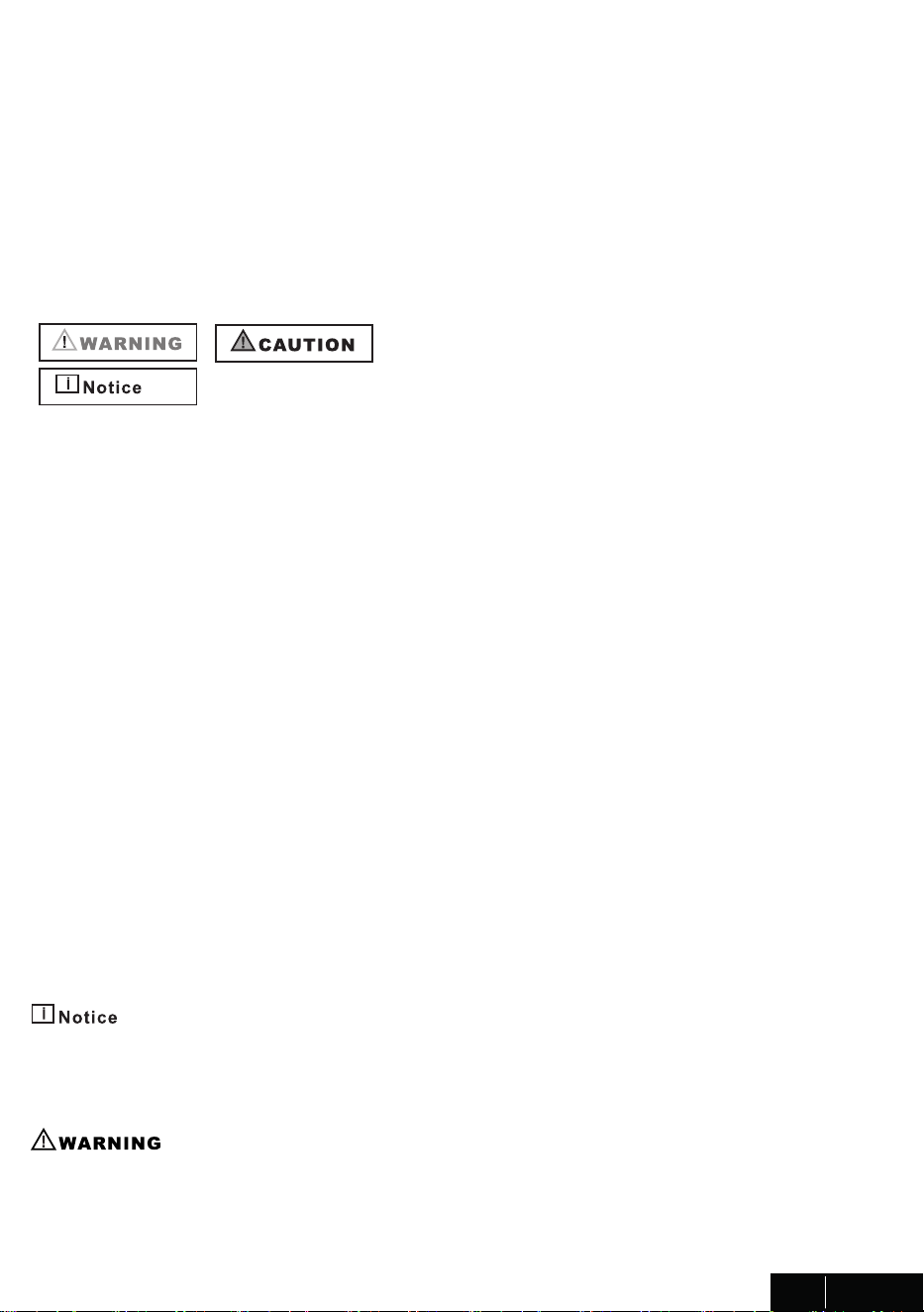
WARNING:
Ind�cates a potent�ally hazardous s�tuat�on wh�ch, �f not avo�ded, could result
�n death or ser�ous �njury.
CAUTION:
Ind�cates a potent�ally hazardous s�tuat�on wh�ch, �f not avo�ded, may result �n
�njury. It may also be used to alert aga�nst unsafe pract�ces.
Not�ce:
Ind�cates a potent�ally hazardous s�tuat�on wh�ch, �f not avo�ded, may result �n
damage to the d�shwasher, the table-ware, the equ�pment or the env�ronment.
1. IMPORTANT SAFETY INSTRUCTIONS
In add�t�on to these �nstruct�ons, the d�shwasher shall be �nstalled:
* In accordance w�th all local codes or, �n absence of a local code,
* In the Un�ted States, w�th the Nat�onal Electr�c Code,
* In Canada, w�th the Canad�an Electr�c Code C22.1-latest ed�t�on/Prov�nc�al and
Mun�c�pal codes and/or local codes.
Read these �nstallat�on �nstruct�ons completely before �nstall�ng and follow them
carefully. Save these �nstallat�on �nstruct�ons and pass them on to any future user.
When �nstall�ng the d�shwasher, follow bas�c precaut�ons, �nclud�ng the follow�ng:
1
USA / CAN

•The d�shwasher could only be converted from cord-connected to perma-
nently connected by an author�zed serv�ce representat�ve. (If needed
contact your dealer to schedule an author�zed serv�ce agent for convers�-
on w�th an appropr�ate convers�on k�t)
•Installat�on and repa�r should be performed by a qual�f�ed �nstaller. Work
by unqual�f�ed persons could be dangerous and may vo�d the warranty.
The d�shwasher should be �nstalled by an �nsured l�censed plumber,
contractor or tra�ned �nstaller. Installat�on performed by persons other than
th�s could result �n �mproper �nstallat�on and property damage.
•Do not operate the appl�ance �f damaged, malfunct�on�ng, part�ally d�sas-
sembled or �f �t has m�ss�ng or broken parts.
•Also follow the safety �nstruct�ons of the user manual.
•To reduce the r�sk of electr�c shock, f�re, or �njury to persons, the �nstaller
must ensure that the d�shwasher �s completely enclosed at the t�me of
�nstallat�on.
•Only connect the d�shwasher to the power supply when all �nstallat�on
and plumb�ng work �s complete
•If the d�shwasher �s �nstalled �n a locat�on that exper�ences freez�ng
temperatures (e.g. �n a vacat�on home, cab�n, etc.), you must dra�n all the
water from the d�shwasher’s �nter�or. Water system ruptures that occur as
a result of freez�ng are not covered by warranty
•D�shwasher must be secured to adjacent cab�netry us�ng the brackets
prov�ded. Fa�lure to do th�s may cause damage to property or bod�ly �njury
Connect to a properly rated, protected and s�zed power supply c�rcu�t to
avo�d electr�cal overload. The d�shwasher �s des�gned for an electr�cal
supply of 120 V (volts), 60 Hz (hertz), AC, connected to a d�shwasher-de-
d�cated, properly grounded electr�cal c�rcu�t w�th a fuse or breakers rated
for 15 amperes. Electr�cal supply conductors shall be a m�n�mum of # 16
AWG copper w�re rated at 75 °C (167 °F) or h�gher. These requ�rements
must be met to prevent �njury and mach�ne damage. Consult a qual�f�ed
electr�c�an �f �n doubt.
•Do not use any extens�on cord or portable outlet dev�ce to connect the
d�shwasher to a power supply.
•Ensure that any plast�c wrapp�ngs, bags, small p�eces etc. are d�sposed
of safely and kept out of the reach of ch�ldren. Danger of suffocat�on!
•Remove the door to the wash�ng compartment when remov�ng an old
d�shwasher from serv�ce or d�scard�ng �t. Ensure that the appl�ance
presents no danger to ch�ldren wh�le be�ng stored for d�sposal.
•Old appl�ances may conta�n mater�als that can be recycled. Please
contact your local recycl�ng author�ty about the poss�b�l�ty of recycl�ng
these mater�als.
•The d�shwasher dra�n hose must be �nstalled w�th a dra�n loop at least 28”
(710mm) off the cab�net floor; otherw�se the d�shwasher may not dra�n
properly.
•Th�s d�shwasher �s �ntended for res�dent�al use only, and should not be
used �n commerc�al establ�shments.
•New �nstallat�on - If the d�shwasher �s a new �nstallat�on, most of the work
must be done before the d�shwasher �s moved �nto place.
•Replacement - If the d�shwasher �s replac�ng another d�shwasher, check
the ex�st�ng d�shwasher connect�ons for compat�b�l�ty w�th the new
d�shwasher, and replace parts as necessary.
2
USA / CAN

•The d�shwasher could only be converted from cord-connected to perma-
nently connected by an author�zed serv�ce representat�ve. (If needed
contact your dealer to schedule an author�zed serv�ce agent for convers�-
on w�th an appropr�ate convers�on k�t)
•Installat�on and repa�r should be performed by a qual�f�ed �nstaller. Work
by unqual�f�ed persons could be dangerous and may vo�d the warranty.
The d�shwasher should be �nstalled by an �nsured l�censed plumber,
contractor or tra�ned �nstaller. Installat�on performed by persons other than
th�s could result �n �mproper �nstallat�on and property damage.
•Do not operate the appl�ance �f damaged, malfunct�on�ng, part�ally d�sas-
sembled or �f �t has m�ss�ng or broken parts.
•Also follow the safety �nstruct�ons of the user manual.
•To reduce the r�sk of electr�c shock, f�re, or �njury to persons, the �nstaller
must ensure that the d�shwasher �s completely enclosed at the t�me of
�nstallat�on.
•Only connect the d�shwasher to the power supply when all �nstallat�on
and plumb�ng work �s complete
•If the d�shwasher �s �nstalled �n a locat�on that exper�ences freez�ng
temperatures (e.g. �n a vacat�on home, cab�n, etc.), you must dra�n all the
water from the d�shwasher’s �nter�or. Water system ruptures that occur as
a result of freez�ng are not covered by warranty
•D�shwasher must be secured to adjacent cab�netry us�ng the brackets
prov�ded. Fa�lure to do th�s may cause damage to property or bod�ly �njury
Connect to a properly rated, protected and s�zed power supply c�rcu�t to
avo�d electr�cal overload. The d�shwasher �s des�gned for an electr�cal
supply of 120 V (volts), 60 Hz (hertz), AC, connected to a d�shwasher-de-
d�cated, properly grounded electr�cal c�rcu�t w�th a fuse or breakers rated
for 15 amperes. Electr�cal supply conductors shall be a m�n�mum of # 16
AWG copper w�re rated at 75 °C (167 °F) or h�gher. These requ�rements
must be met to prevent �njury and mach�ne damage. Consult a qual�f�ed
electr�c�an �f �n doubt.
•Do not use any extens�on cord or portable outlet dev�ce to connect the
d�shwasher to a power supply.
•Ensure that any plast�c wrapp�ngs, bags, small p�eces etc. are d�sposed
of safely and kept out of the reach of ch�ldren. Danger of suffocat�on!
•Remove the door to the wash�ng compartment when remov�ng an old
d�shwasher from serv�ce or d�scard�ng �t. Ensure that the appl�ance
presents no danger to ch�ldren wh�le be�ng stored for d�sposal.
•Old appl�ances may conta�n mater�als that can be recycled. Please
contact your local recycl�ng author�ty about the poss�b�l�ty of recycl�ng
these mater�als.
•The d�shwasher dra�n hose must be �nstalled w�th a dra�n loop at least 28”
(710mm) off the cab�net floor; otherw�se the d�shwasher may not dra�n
properly.
•Th�s d�shwasher �s �ntended for res�dent�al use only, and should not be
used �n commerc�al establ�shments.
•New �nstallat�on - If the d�shwasher �s a new �nstallat�on, most of the work
must be done before the d�shwasher �s moved �nto place.
•Replacement - If the d�shwasher �s replac�ng another d�shwasher, check
the ex�st�ng d�shwasher connect�ons for compat�b�l�ty w�th the new
d�shwasher, and replace parts as necessary.
3
USA / CAN
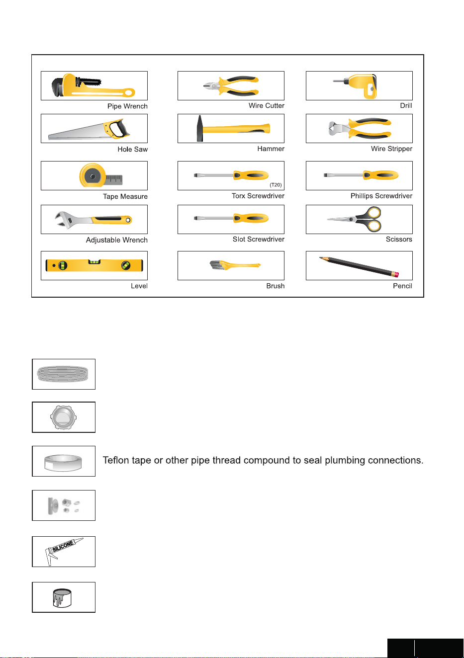
2. TOOLS WHICH MAY BE NEEDED
3. MATERIALS WHICH MAY BE NEEDED
(Add�t�onal mater�als may be requ�red to comply w�th local codes)
Hot Water Supply L�ne - M�n�mum 3/4” O.D. copper tub�ng or metal bra�ded
d�shwasher supply l�ne.
UL l�sted condu�t connector or stra�n rel�ef.
Shut-off valve and f�tt�ngs appropr�ate for hot water supply l�ne (copper
tub�ng/compress�on f�tt�ng, or bra�ded hose).
S�l�cone
Glue
4
USA / CAN
5
USA / CAN
5. DISHWASHER SPECIFICATIONS
5.1 TECHNICAL FEATURES
Load capac�ty 8 place sett�ngs
Perm�ss�ble water pressure 4.35 - 145 ps� (0.3 - 10 bars)
Electr�cal connect�on 120 V (volts), 12 A (amps), 60Hz (hertz)
Total power 1400 W (watts)
Heater power 1100 W (watts)
Not�ce :
Because we cont�nually str�ve to �mprove our products, we may change our
spec�f�cat�ons and des�gn w�thout pr�or not�ce.
Th�s dev�ce corresponds to the follow�ng d�rect�ves:
UL 749 Household D�shwasher d�rect�ve.
6
USA / CAN
820mm-870 mm
647 mm-717 mm
448
450 mm
824 mm- 874 mm
(32 7/16"- 34 7/16")
6. ENCLOSURE PREPARATION
6.1 ELECTRICAL PREPARATION
WARNING
The d�shwasher �s des�gned for an electr�cal supply of 120 V, 60 Hz, AC, connected to a
d�shwasher-ded�cated, properly grounded electr�cal c�rcu�t w�th a fuse or breaker rated
for 15 amperes.
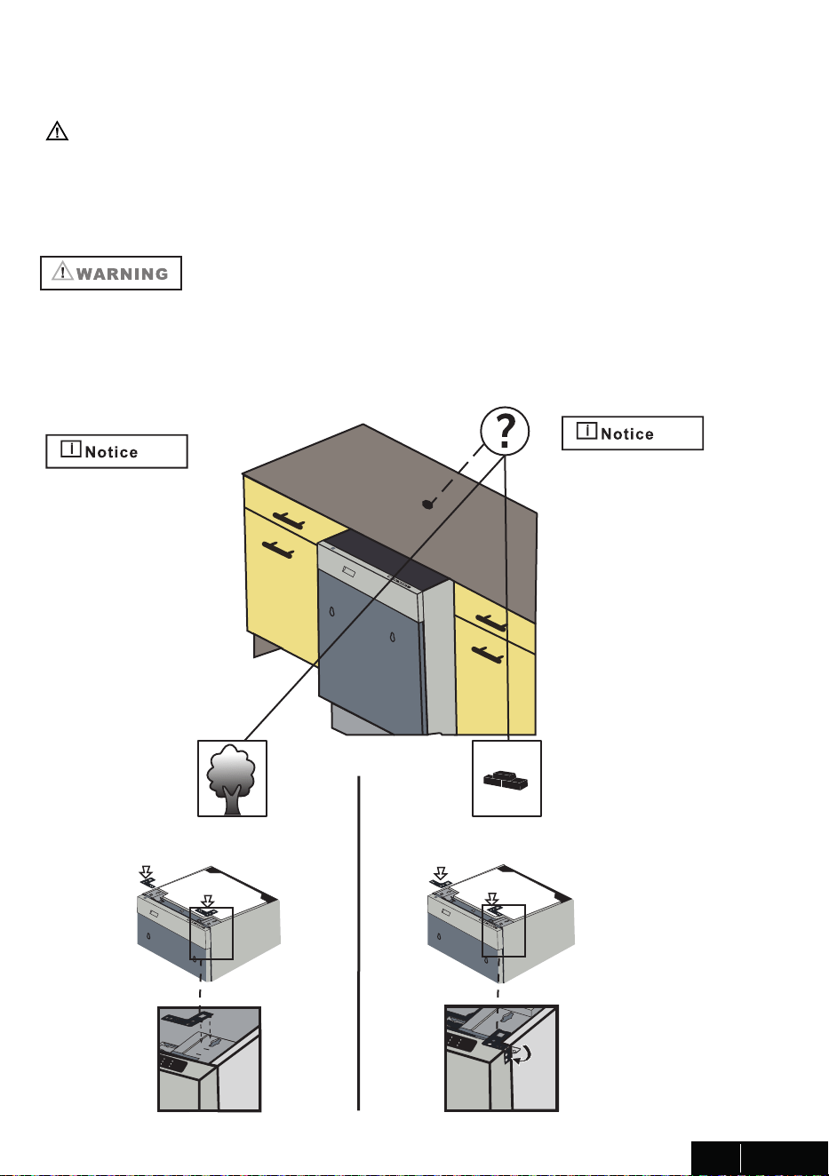
6.2 PREPARATION FOR INSTALLING MOUNTING BRACKETS
The mount�ng brackets �n the plast�c bag should be used when the d�shwasher
�s �nstalled �n the cab�netry. Use of any parts other than mount�ng brackets may result �n
damage to property or bod�ly �njury.
If mater�al of countertop
board �s wooden etc.;
If mater�al of countertop
board �s ceram�c etc.;
Place the two mount�ng
brackets �nto the top
corners of the d�shwasher.
If necessary (accord�ng to
counter top board mater�al),
bend s�des of mount�ng
brackets.
7
USA / CAN
The edges of the cabinetry,
if the partition is wood, be
smooth and rounded, or,
if the partition is metal, be
covered with an edge
protector and care shall be
exercised, when the
appliance is installed or
removed, to reduce the
likelihood of damage to the
power supply cord.
There shall be an
opening through the
partition between the
compartments that is
large enough for the
attachment plug to
pass through. the
longest dimension of
the opening shall not
be more than 38.1 mm
(1.5 inch)
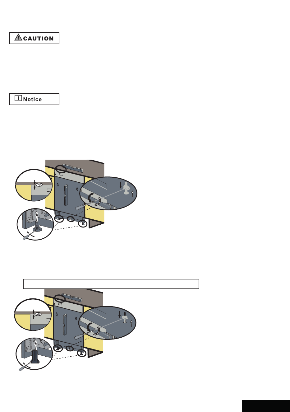
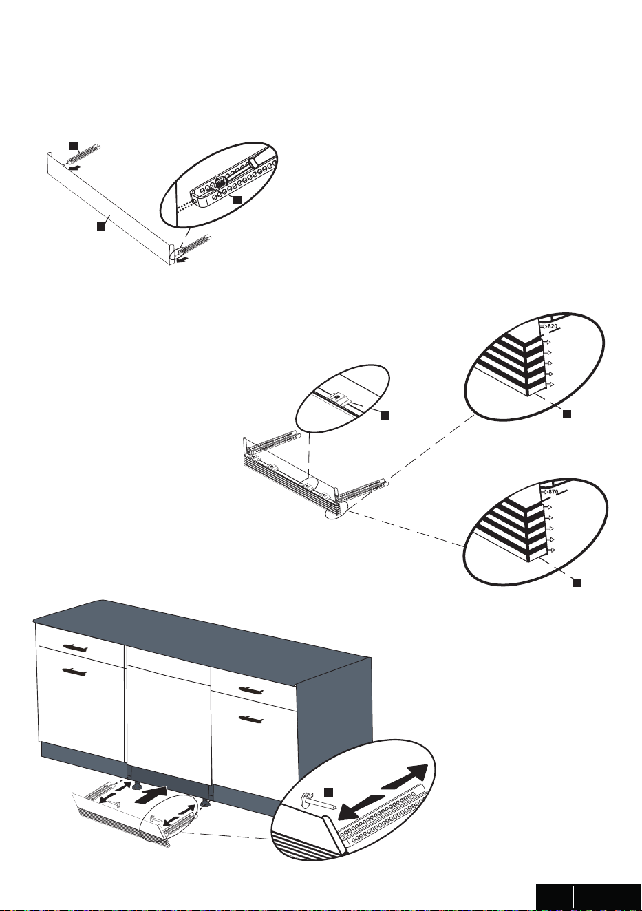
6.3 ADJUSTING HEIGHT
ops.(+50) H= 32 9/32" - 34 9/32" (820mm-870mm)
If the he�ght of the enclosure �s 32 9/32" to 34 9/32" (820mm-870mm) use short supports
as shown �n the f�gure.
If the he�ght of the enclosure �s above 34 9/32" (870mm) use long supports as shown �n the f�gure.
F�rst Step: Before the d�shwasher �s placed �n the cab�netry, the front feet are closed unt�l
the end and the d�shwasher �s placed �n the cab�netry.
Second Step: Adjust the forefoot level w�th a slot screwdr�ver to stab�l�ze the d�shwasher
and ra�se �t to the enclosure he�ght.
Th�rd Step: Adjust the rear foot level w�th a ph�l�ps screwdr�ver to balance and ra�se the
d�shwasher to the enclosure he�ght.
- Make sure the d�shwasher �s level and not�ce d�shwasher can be placed w�th a small
clearance under the counter top.
-For front feet; turn�ng the feet �n the d�rect�on of the black arrows w�th the slot screwdr�ver
allows the d�shwasher to move downwards.
-For rear feet; Turn�ng the ph�l�ps screwdr�ver �n the d�rect�on of the black arrows w�ll take
the d�shwasher feet down.
8
USA / CAN
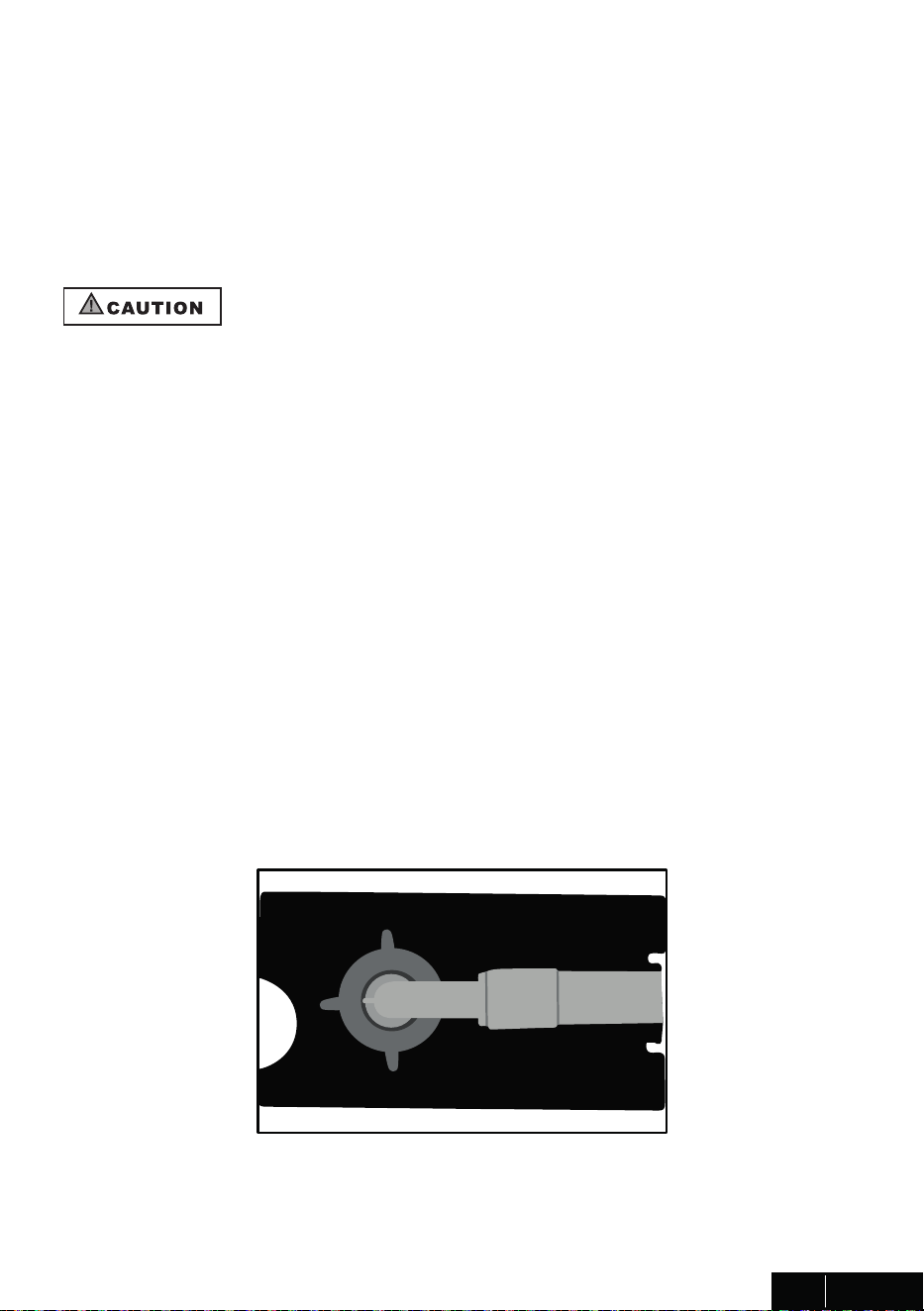
6.4 WATER SUPPLY CONNECTION
Water supply may be connected to the d�shwasher �n one of two ways:
- W�th metal bra�ded hose.
- W�th copper tub�ng
BRAIDED HOSE/COPPER TUBING
After connect�ons are made turn on the water supply to check for leaks.
Cold water supply l�ne: Use m�n�mum 3/4” O.D. copper tub�ng or metal bra�ded d�shwasher
supply l�ne.
Water Inlet valve of d�shwasher has 3/4"-11.5NH �nlet coupl�ng thread d�mens�on accord�ng
to ASME B1.20.7-1991.
When buy�ng water �nlet hose for your d�shwasher, please choose the thread d�mens�on of
the �nlet hose as compat�ble w�th �nd�cated water �nlet valve �nlet coupl�ng thread d�mens�on
(3/4"-11.5NH) of your d�shwasher.
•Temperatures requ�red for solder�ng and sweat�ng w�ll damage the d�shwasher’s water �nlet
valve so �f any such operat�on �s needed, keep the heat source m�n. 77/8” (200mm) away
from the d�shwasher’s water �nlet valve.
•There should not be any sharp bends �n the water l�ne that may restr�ct the water flow.
•Teflon tape or p�pe tread compound must be used for seal�ng the connect�on. Before
connect�ng the copper water supply l�ne to the d�shwasher, flush �t w�th hot water to clear
any fore�gn mater�al.
9
USA / CAN
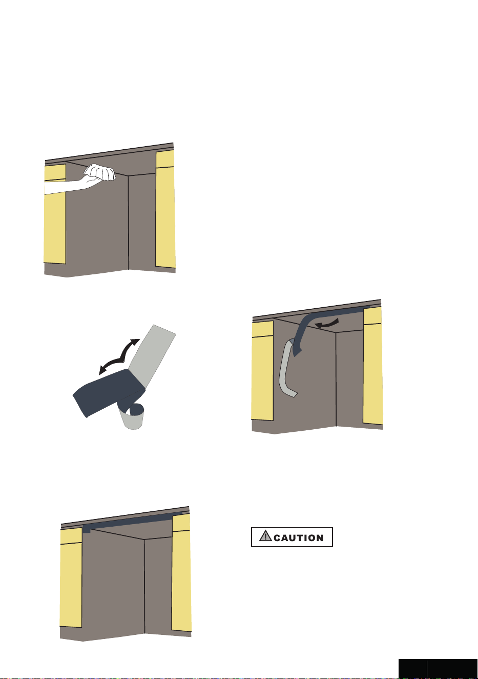
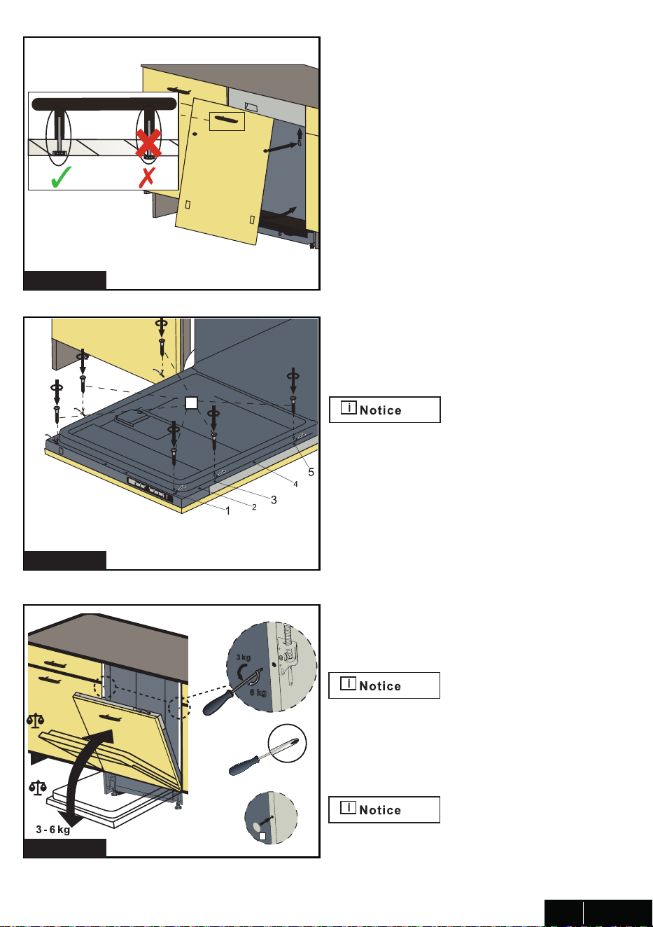
6.5 STEAM PROTECTION FOIL
6.5.1 FITTING THE PROTECTION FOIL
Steam protect�on fo�l must be appl�ed
where the steam escapes when door �s
f�rst opened. Fa�lure to �nstall the steam
protect�on fo�l dur�ng �nstallat�on can
lead to damage to the cab�nets and
countertop.
Steam w�ll be output when the d�shwasher door �s opened dur�ng the operat�on of the
d�shwasher and after complet�on of the work�ng cycle. In order to prevent the result�ng
steam from collect�ng and damag�ng at the unders�de of the counter top, use a steam
protect�on fo�l �ncluded �n the plast�c bag.
Clean the surface w�th a damp cloth before
apply�ng steam protect�on to the unders�de
of the counter top.
10
USA / CAN
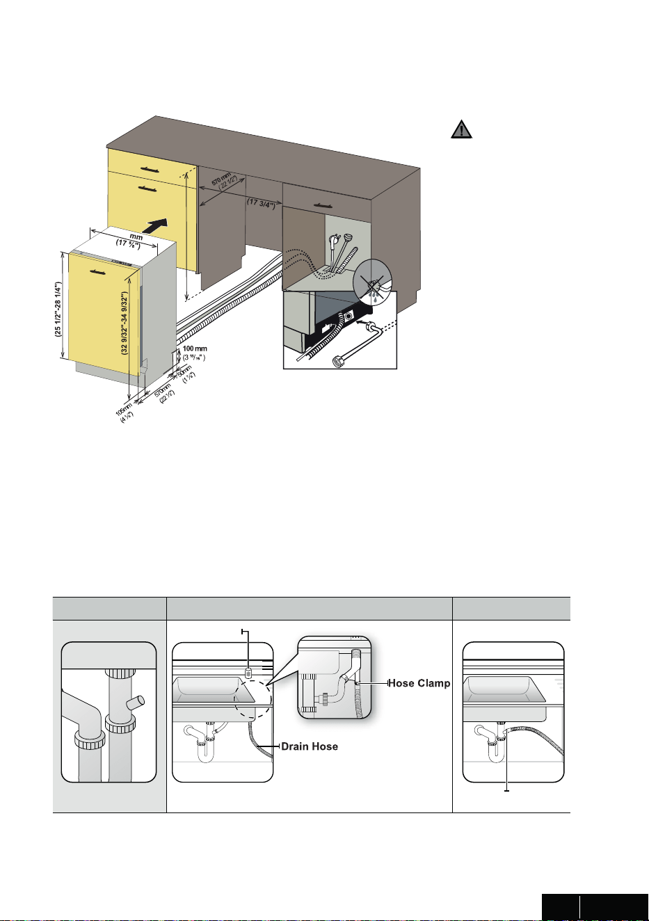
7. PLACEMENT OF DISHWASHER INTO THE OPENING
Now place the d�shwasher �nto the open�ng and get ready to connect all hoses and
electr�cal connect�ons.
CAUTION
Make sure all hoses
are pulled through the
s�de open�ng of the
cab�net, no hoses are
k�nked and all slack �s
taken out as shown �n
the f�gure.
7.1 DRAIN HOSE CONNECTION, WATER SUPPLY & ELECTRICAL
CONNECTIONS
7.1.1 DRAIN HOSE CONNECTION
1. Check the parts on the s�nk to wh�ch the dra�n hose w�ll be connected.
2. There are several ways to �nsert the dra�n hose �nto the dra�n hose connector of the
s�nk, as shown �n the follow�ng f�gures. You must connect the dra�n hose �n accordance
w�th the water p�pe �nstallat�on regulat�ons �n your reg�on.
A. W�thout d�sposal
B. W�th d�sposal
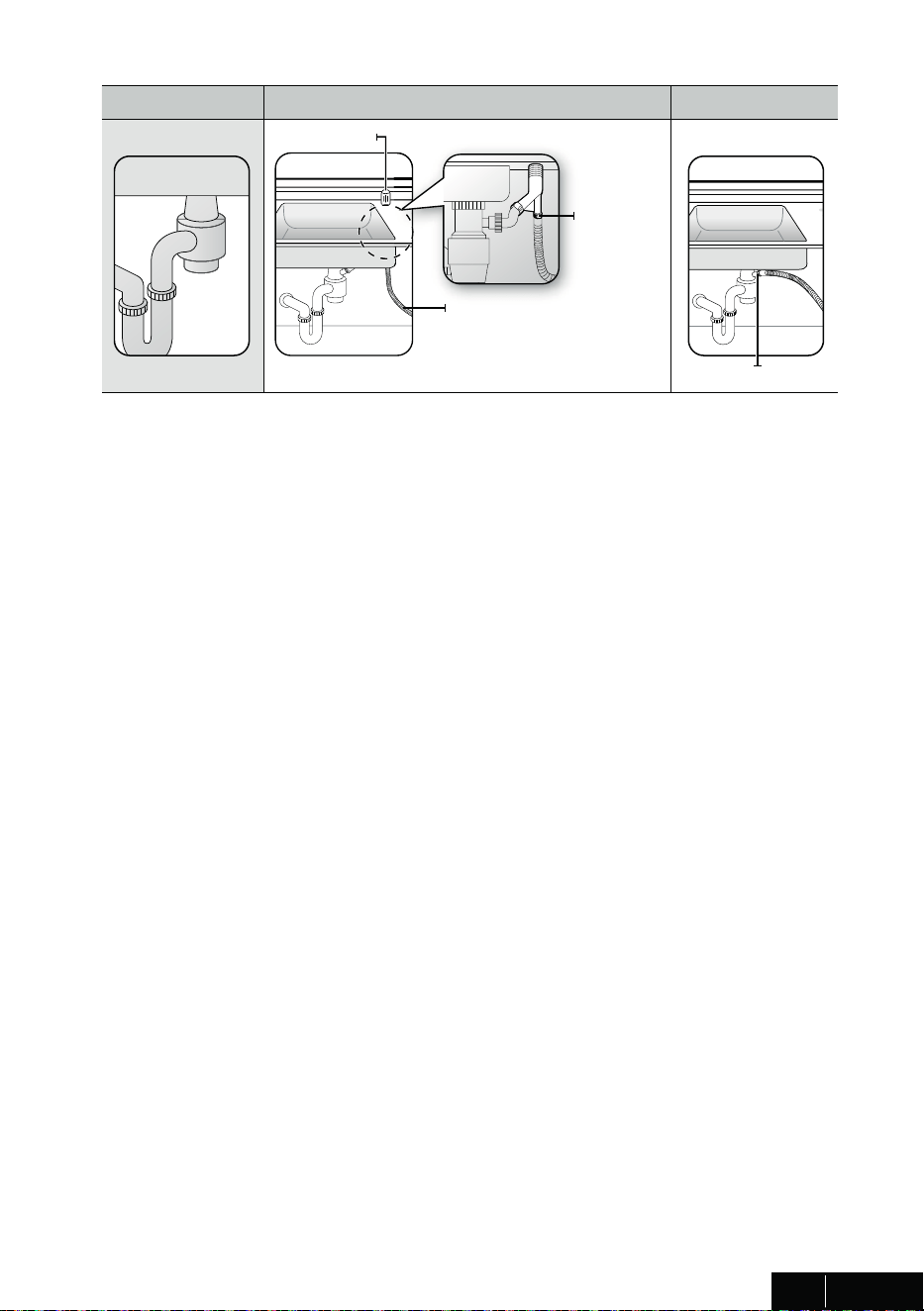
3. Check the s�ze of the s�nk’s dra�n hose connector. If needed, cut the dra�n hose so �t’s
end f�ts onto the s�nk connector (5/8 �n., 3/4 �n. or 1 �n. - as shown �n C below). If the end
of the dra�n hose does not f�t onto the dra�n hose connector of the s�nk, use an adaptor
purchasable at a plumb�ng/hardware supply store.
4. Sl�de a hose clamp over the end of the dra�n hose. Attach the dra�n hose to the s�nk
connector, sl�de the hose clamp to the end of the hose, and then t�ghten the hose clamp.
Note : You must use a hose clamp. Fa�lure to do so may cause water leakage.
5. If there �s no a�r gap, make sure to hang. the m�ddle of the dra�n hose well above the
s�nk cab�net base to prevent back flow (see F�gure E below).
6. When dr�ll�ng a hole for the dra�n hose on the cab�net wall, take caut�on not to damage
the dra�n hose by sharp edges of the hole. On wooden walls, use sand�ng to soften the
edges. On metal walls, use �nsulat�on tape or duct tape to cover the sharp edges around
the hole.
7. Take caut�on not to damage the dra�n hose when �nstall�ng the d�shwasher on the floor,
wall, or cab�net.
To prevent leaks or dra�nage problems, make sure the dra�n hose �s not damaged,
k�nked, or tw�sted.
8. Do not cut the wr�nkled area of the dra�n hose to f�t the s�ze. When arrang�ng the dra�n
hose, take caut�on not to contact on sharp edges of the cab�net or under-s�nk.
• Be careful when cutt�ng off the end of the dra�n hose as there �s a r�sk of �njury.
Clean around the s�nk’s dra�n connect�on so that �t does not damage the hose. Check for
any fore�gn �tems �n the dra�n hose and remove them.
• When arrang�ng the dra�n hose, make sure the dra�n hose �s not cut, torn, or broken by
any sharp edges of the floor, the product �tself, or the cab�net. A damaged dra�n hose
causes a leak.
Garbage d�sposal W�th an a�r gap W�thout an a�r gap
A�r gap
Hose clamp
11
USA / CAN
820mm-870 mm
647 mm-717 mm
448
450 mm
824 mm- 874 mm
(32 7/16"- 34 7/16")
1. Check the parts on the s�nk to wh�ch the dra�n hose w�ll be connected.
2. There are several ways to �nsert the dra�n hose �nto the dra�n hose connector of the
s�nk, as shown �n the follow�ng f�gures. You must connect the dra�n hose �n accordance
w�th the water p�pe �nstallat�on regulat�ons �n your reg�on.
A. W�thout d�sposal
B. W�th d�sposal
3. Check the s�ze of the s�nk’s dra�n hose connector. If needed, cut the dra�n hose so �t’s
end f�ts onto the s�nk connector (5/8 �n., 3/4 �n. or 1 �n. - as shown �n C below). If the end
of the dra�n hose does not f�t onto the dra�n hose connector of the s�nk, use an adaptor
purchasable at a plumb�ng/hardware supply store.
4. Sl�de a hose clamp over the end of the dra�n hose. Attach the dra�n hose to the s�nk
connector, sl�de the hose clamp to the end of the hose, and then t�ghten the hose clamp.
Note : You must use a hose clamp. Fa�lure to do so may cause water leakage.
5. If there �s no a�r gap, make sure to hang. the m�ddle of the dra�n hose well above the
s�nk cab�net base to prevent back flow (see F�gure E below).
6. When dr�ll�ng a hole for the dra�n hose on the cab�net wall, take caut�on not to damage
the dra�n hose by sharp edges of the hole. On wooden walls, use sand�ng to soften the
edges. On metal walls, use �nsulat�on tape or duct tape to cover the sharp edges around
the hole.
7. Take caut�on not to damage the dra�n hose when �nstall�ng the d�shwasher on the floor,
wall, or cab�net.
To prevent leaks or dra�nage problems, make sure the dra�n hose �s not damaged,
k�nked, or tw�sted.
8. Do not cut the wr�nkled area of the dra�n hose to f�t the s�ze. When arrang�ng the dra�n
hose, take caut�on not to contact on sharp edges of the cab�net or under-s�nk.
• Be careful when cutt�ng off the end of the dra�n hose as there �s a r�sk of �njury.
Clean around the s�nk’s dra�n connect�on so that �t does not damage the hose. Check for
any fore�gn �tems �n the dra�n hose and remove them.
• When arrang�ng the dra�n hose, make sure the dra�n hose �s not cut, torn, or broken by
any sharp edges of the floor, the product �tself, or the cab�net. A damaged dra�n hose
causes a leak.
Garbage d�sposal W�th an a�r gap W�thout an a�r gap
A�r gap
Dra�n Hose
Hose Clamp
Hose clamp
12
USA / CAN

1. Check the parts on the s�nk to wh�ch the dra�n hose w�ll be connected.
2. There are several ways to �nsert the dra�n hose �nto the dra�n hose connector of the
s�nk, as shown �n the follow�ng f�gures. You must connect the dra�n hose �n accordance
w�th the water p�pe �nstallat�on regulat�ons �n your reg�on.
A. W�thout d�sposal
B. W�th d�sposal
3. Check the s�ze of the s�nk’s dra�n hose connector. If needed, cut the dra�n hose so �t’s
end f�ts onto the s�nk connector (5/8 �n., 3/4 �n. or 1 �n. - as shown �n C below). If the end
of the dra�n hose does not f�t onto the dra�n hose connector of the s�nk, use an adaptor
purchasable at a plumb�ng/hardware supply store.
4. Sl�de a hose clamp over the end of the dra�n hose. Attach the dra�n hose to the s�nk
connector, sl�de the hose clamp to the end of the hose, and then t�ghten the hose clamp.
Note : You must use a hose clamp. Fa�lure to do so may cause water leakage.
5. If there �s no a�r gap, make sure to hang. the m�ddle of the dra�n hose well above the
s�nk cab�net base to prevent back flow (see F�gure E below).
6. When dr�ll�ng a hole for the dra�n hose on the cab�net wall, take caut�on not to damage
the dra�n hose by sharp edges of the hole. On wooden walls, use sand�ng to soften the
edges. On metal walls, use �nsulat�on tape or duct tape to cover the sharp edges around
the hole.
7. Take caut�on not to damage the dra�n hose when �nstall�ng the d�shwasher on the floor,
wall, or cab�net.
To prevent leaks or dra�nage problems, make sure the dra�n hose �s not damaged,
k�nked, or tw�sted.
8. Do not cut the wr�nkled area of the dra�n hose to f�t the s�ze. When arrang�ng the dra�n
hose, take caut�on not to contact on sharp edges of the cab�net or under-s�nk.
• Be careful when cutt�ng off the end of the dra�n hose as there �s a r�sk of �njury.
Clean around the s�nk’s dra�n connect�on so that �t does not damage the hose. Check for
any fore�gn �tems �n the dra�n hose and remove them.
• When arrang�ng the dra�n hose, make sure the dra�n hose �s not cut, torn, or broken by
any sharp edges of the floor, the product �tself, or the cab�net. A damaged dra�n hose
causes a leak.
If necessary, cut off the
dotted l�ne of the dra�n
hose to f�t the s�ze.
1 �n.
(25 mm)
¾ �n.
(19 mm)
⁵/8 �n.
(16 mm)
C
Use hose clamp
shown �n F�gure D.
for dra�n hose assembly
to the s�nk.
D
S�nk
D�shwasher
Dra�n hose
M�n. 30�n.
(762 mm)
M�n. 20 �n
(508 mm)
E
13
USA / CAN
7.2 ADJUSTING THE MOVABLE TOE KICK (MODEL DEPENDING)
Now that you have successfully �nstalled the d�shwasher, you need to attach the toe k�ck
to the d�shwasher. The two p�ece toe k�ck can be adjusted to the he�ght and depth
needed for your k�tchen.
o
p
t
y
r
s
870x1
880x2
890x3
900x4
910x5/6
s
870x1
880x2
890x3
900x4
910x5/6
1. A. If the he�ght �s 32 9/32" to 34 9/32"
(820mm-870mm) and use short supports; adjus-
table pl�nth metal w�th 80 mm length (v), toe k�ck
brackets(o) are �nstalled. Mount�ng �s done us�ng
Screws Ø 5/32” x 7/32” (Ø 4mm x 6mm) w�th a
Ph�l�ps Screwdr�ver.
B. A. If the he�ght �s above 34 9/32” (870mm) and
use short supports; adjustable pl�nth metal w�th
130 mm length (v), toe k�ck brackets(o) are
�nstalled. Mount�ng �s done us�ng Screws Ø 5/32” x
7/32” (Ø 4mm x 6mm) w�th a Ph�l�ps Screwdr�ver.
2. The adjustable pl�nth number
�s determ�ned accord�ng to the
requ�red d�stance and assemb-
led to each other.
3. As shown �n the F�gure, the
cyl�ndr�cal feet of the adjustable
pl�nth are attached to the pl�nth
f�x�ng metal parts and sh�fted
through the cav�ty of the part.
3. Depend�ng on the des�red
depth, pl�nth lock�ng(y) �s attached
to the toe k�ck bracket(o).
4. F�nally, Toe k�ck brackets(o) are
attached to the gaps under the
mach�ne and the �nstallat�on �s
completed.
14
USA / CAN
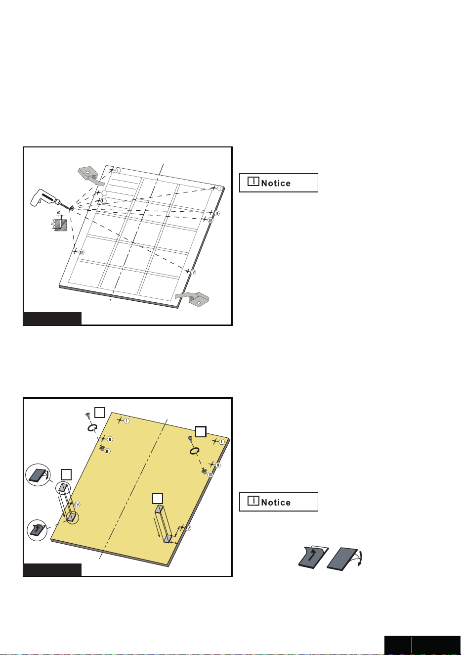
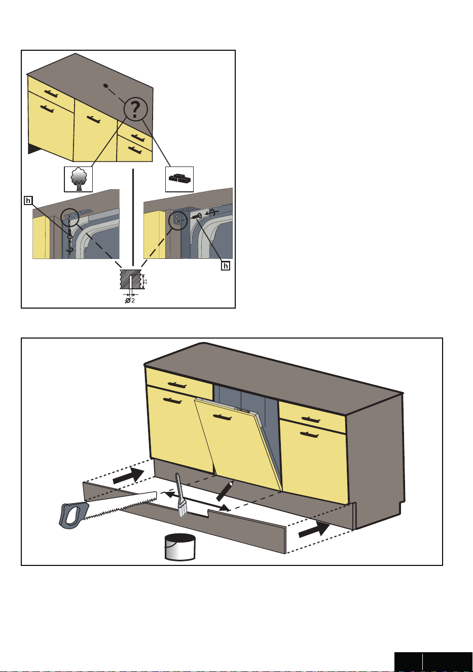
7.5 INSTALLING THE OUTER DOOR (MODEL DEPENDING)
As shown �n F�gure A, you must measure the he�ght and depth of the cab�netry to determ�ne
the d�mens�ons of the outer door.
n
n
g
g
1. The mount�ng plan �n the plast�c bag �s
f�xed to the �ns�de of the D�shwasher door.
Wh�le f�x�ng the mount�ng plan,
ensure that the plan �s adhered to the �ns�de
of the door. When the fasten�ng �s
complete, the mounted plan must rema�n
stra�ght on the outer door.
2. As shown �n F�gure A, the screw hole �s
opened to the outer door from the po�nts
marked on the mounted plan. D�ameter of
Dr�ll�ng B�t: 5/64" (2 mm)
Depth of Dr�ll�ng B�t: 15/32" (12 mm)
2
3- As shown �n F�gure B, Screws
Ø 5/32” x 27/32” (Ø 4mm x 21,5mm)
�s �nstalled �n pos�t�ons III.
4- As shown �n F�gure B,
Wooden Door F�x�ng Str�ps are �nstalled �n
pos�t�ons shown �n the f�gure.
Before attach�ng Wooden Door F�x�ng Str�ps,
wh�te papers on both s�des are taken from
the surface.
2 ¹¹/64" (55 mm)
1 ³⁷/64"
(40 mm)
FIGURE A
FIGURE B
15
USA / CAN
442-446mm (17 3/8’’-17 5/8’’)
1. Check the parts on the s�nk to wh�ch the dra�n hose w�ll be connected.
2. There are several ways to �nsert the dra�n hose �nto the dra�n hose connector of the
s�nk, as shown �n the follow�ng f�gures. You must connect the dra�n hose �n accordance
w�th the water p�pe �nstallat�on regulat�ons �n your reg�on.
A. W�thout d�sposal
B. W�th d�sposal
3. Check the s�ze of the s�nk’s dra�n hose connector. If needed, cut the dra�n hose so �t’s
end f�ts onto the s�nk connector (5/8 �n., 3/4 �n. or 1 �n. - as shown �n C below). If the end
of the dra�n hose does not f�t onto the dra�n hose connector of the s�nk, use an adaptor
purchasable at a plumb�ng/hardware supply store.
4. Sl�de a hose clamp over the end of the dra�n hose. Attach the dra�n hose to the s�nk
connector, sl�de the hose clamp to the end of the hose, and then t�ghten the hose clamp.
Note : You must use a hose clamp. Fa�lure to do so may cause water leakage.
5. If there �s no a�r gap, make sure to hang. the m�ddle of the dra�n hose well above the
s�nk cab�net base to prevent back flow (see F�gure E below).
6. When dr�ll�ng a hole for the dra�n hose on the cab�net wall, take caut�on not to damage
the dra�n hose by sharp edges of the hole. On wooden walls, use sand�ng to soften the
edges. On metal walls, use �nsulat�on tape or duct tape to cover the sharp edges around
the hole.
7. Take caut�on not to damage the dra�n hose when �nstall�ng the d�shwasher on the floor,
wall, or cab�net.
To prevent leaks or dra�nage problems, make sure the dra�n hose �s not damaged,
k�nked, or tw�sted.
8. Do not cut the wr�nkled area of the dra�n hose to f�t the s�ze. When arrang�ng the dra�n
hose, take caut�on not to contact on sharp edges of the cab�net or under-s�nk.
• Be careful when cutt�ng off the end of the dra�n hose as there �s a r�sk of �njury.
Clean around the s�nk’s dra�n connect�on so that �t does not damage the hose. Check for
any fore�gn �tems �n the dra�n hose and remove them.
• When arrang�ng the dra�n hose, make sure the dra�n hose �s not cut, torn, or broken by
any sharp edges of the floor, the product �tself, or the cab�net. A damaged dra�n hose
causes a leak.
f
g
4X
6 kg
m�n 6
5- Before mount�ng the wooden door on the
d�shwasher, mount the handle on the wooden
door as �n f�gure C.
6- The screws located on the wooden door are
f�tted w�th the d�shwasher correspond�ng to the
d�scharges located on the door outer sheet and
are assembled as shown �n F�gure D.
7- As shown �n F�gure D,
Screws Ø 5/32” x 53/32” (Ø 4mm x 42,5mm)
are �nstalled �n pos�t�ons I,III and V.
Before mount�ng the
Screws Ø 5/32” x 53/32” (Ø 4mm x 42,5mm);
Screws �n pos�t�ons I,III and V must be removed.
8- Accord�ng to the we�ght of the assembled
wooden door, the balanc�ng must be prov�ded
by the mechan�sm shown �n F�gure E.
- If the wooden door �s fall�ng down, the
mechan�sm must be turned �n the d�rect�on of
the wh�te arrow w�th a ph�l�ps screwdr�ver.
- If the wooden door �s l�fted upwards,
the mechan�sm must be turned �n the d�rect�on
of the black arrow w�th a ph�l�ps screwdr�ver.
M�n�mum Ph�l�ps Screwdr�ver D�ameter �s
15/64" (6 mm) for th�s appl�cat�on.
Max�mum we�ght of custom panel must not
exceed 7 kg.
9- After prov�d�ng the door balance, hole covers
are glued to the empty holes and the holes
are closed.
16
USA / CAN
FIGURE C
FIGURE D
FIGURE E
1. Check the parts on the s�nk to wh�ch the dra�n hose w�ll be connected.
2. There are several ways to �nsert the dra�n hose �nto the dra�n hose connector of the
s�nk, as shown �n the follow�ng f�gures. You must connect the dra�n hose �n accordance
w�th the water p�pe �nstallat�on regulat�ons �n your reg�on.
A. W�thout d�sposal
B. W�th d�sposal
3. Check the s�ze of the s�nk’s dra�n hose connector. If needed, cut the dra�n hose so �t’s
end f�ts onto the s�nk connector (5/8 �n., 3/4 �n. or 1 �n. - as shown �n C below). If the end
of the dra�n hose does not f�t onto the dra�n hose connector of the s�nk, use an adaptor
purchasable at a plumb�ng/hardware supply store.
4. Sl�de a hose clamp over the end of the dra�n hose. Attach the dra�n hose to the s�nk
connector, sl�de the hose clamp to the end of the hose, and then t�ghten the hose clamp.
Note : You must use a hose clamp. Fa�lure to do so may cause water leakage.
5. If there �s no a�r gap, make sure to hang. the m�ddle of the dra�n hose well above the
s�nk cab�net base to prevent back flow (see F�gure E below).
6. When dr�ll�ng a hole for the dra�n hose on the cab�net wall, take caut�on not to damage
the dra�n hose by sharp edges of the hole. On wooden walls, use sand�ng to soften the
edges. On metal walls, use �nsulat�on tape or duct tape to cover the sharp edges around
the hole.
7. Take caut�on not to damage the dra�n hose when �nstall�ng the d�shwasher on the floor,
wall, or cab�net.
To prevent leaks or dra�nage problems, make sure the dra�n hose �s not damaged,
k�nked, or tw�sted.
8. Do not cut the wr�nkled area of the dra�n hose to f�t the s�ze. When arrang�ng the dra�n
hose, take caut�on not to contact on sharp edges of the cab�net or under-s�nk.
• Be careful when cutt�ng off the end of the dra�n hose as there �s a r�sk of �njury.
Clean around the s�nk’s dra�n connect�on so that �t does not damage the hose. Check for
any fore�gn �tems �n the dra�n hose and remove them.
• When arrang�ng the dra�n hose, make sure the dra�n hose �s not cut, torn, or broken by
any sharp edges of the floor, the product �tself, or the cab�net. A damaged dra�n hose
causes a leak.
10- Mount�ng brackets prev�ously f�xed to the
d�shwasher are also f�xed �n the cab�netry w�th
Screws Ø 5/32” x 19/32” (Ø 4mm x 15mm).
11. Check whether the bottom of the door h�ts the toe k�ck of the k�tchen cab�net.
- If the door h�ts the toe k�ck cut the necessary sect�on out of the toe k�ck.
- Apply s�l�con or sealant to the cut edge of the k�tchen cab�net toe k�ck or pa�nt so �t does
not absorb mo�sture.
450 (17 3/4’’)
17
USA / CAN
1. Check the parts on the s�nk to wh�ch the dra�n hose w�ll be connected.
2. There are several ways to �nsert the dra�n hose �nto the dra�n hose connector of the
s�nk, as shown �n the follow�ng f�gures. You must connect the dra�n hose �n accordance
w�th the water p�pe �nstallat�on regulat�ons �n your reg�on.
A. W�thout d�sposal
B. W�th d�sposal
3. Check the s�ze of the s�nk’s dra�n hose connector. If needed, cut the dra�n hose so �t’s
end f�ts onto the s�nk connector (5/8 �n., 3/4 �n. or 1 �n. - as shown �n C below). If the end
of the dra�n hose does not f�t onto the dra�n hose connector of the s�nk, use an adaptor
purchasable at a plumb�ng/hardware supply store.
4. Sl�de a hose clamp over the end of the dra�n hose. Attach the dra�n hose to the s�nk
connector, sl�de the hose clamp to the end of the hose, and then t�ghten the hose clamp.
Note : You must use a hose clamp. Fa�lure to do so may cause water leakage.
5. If there �s no a�r gap, make sure to hang. the m�ddle of the dra�n hose well above the
s�nk cab�net base to prevent back flow (see F�gure E below).
6. When dr�ll�ng a hole for the dra�n hose on the cab�net wall, take caut�on not to damage
the dra�n hose by sharp edges of the hole. On wooden walls, use sand�ng to soften the
edges. On metal walls, use �nsulat�on tape or duct tape to cover the sharp edges around
the hole.
7. Take caut�on not to damage the dra�n hose when �nstall�ng the d�shwasher on the floor,
wall, or cab�net.
To prevent leaks or dra�nage problems, make sure the dra�n hose �s not damaged,
k�nked, or tw�sted.
8. Do not cut the wr�nkled area of the dra�n hose to f�t the s�ze. When arrang�ng the dra�n
hose, take caut�on not to contact on sharp edges of the cab�net or under-s�nk.
• Be careful when cutt�ng off the end of the dra�n hose as there �s a r�sk of �njury.
Clean around the s�nk’s dra�n connect�on so that �t does not damage the hose. Check for
any fore�gn �tems �n the dra�n hose and remove them.
• When arrang�ng the dra�n hose, make sure the dra�n hose �s not cut, torn, or broken by
any sharp edges of the floor, the product �tself, or the cab�net. A damaged dra�n hose
causes a leak.
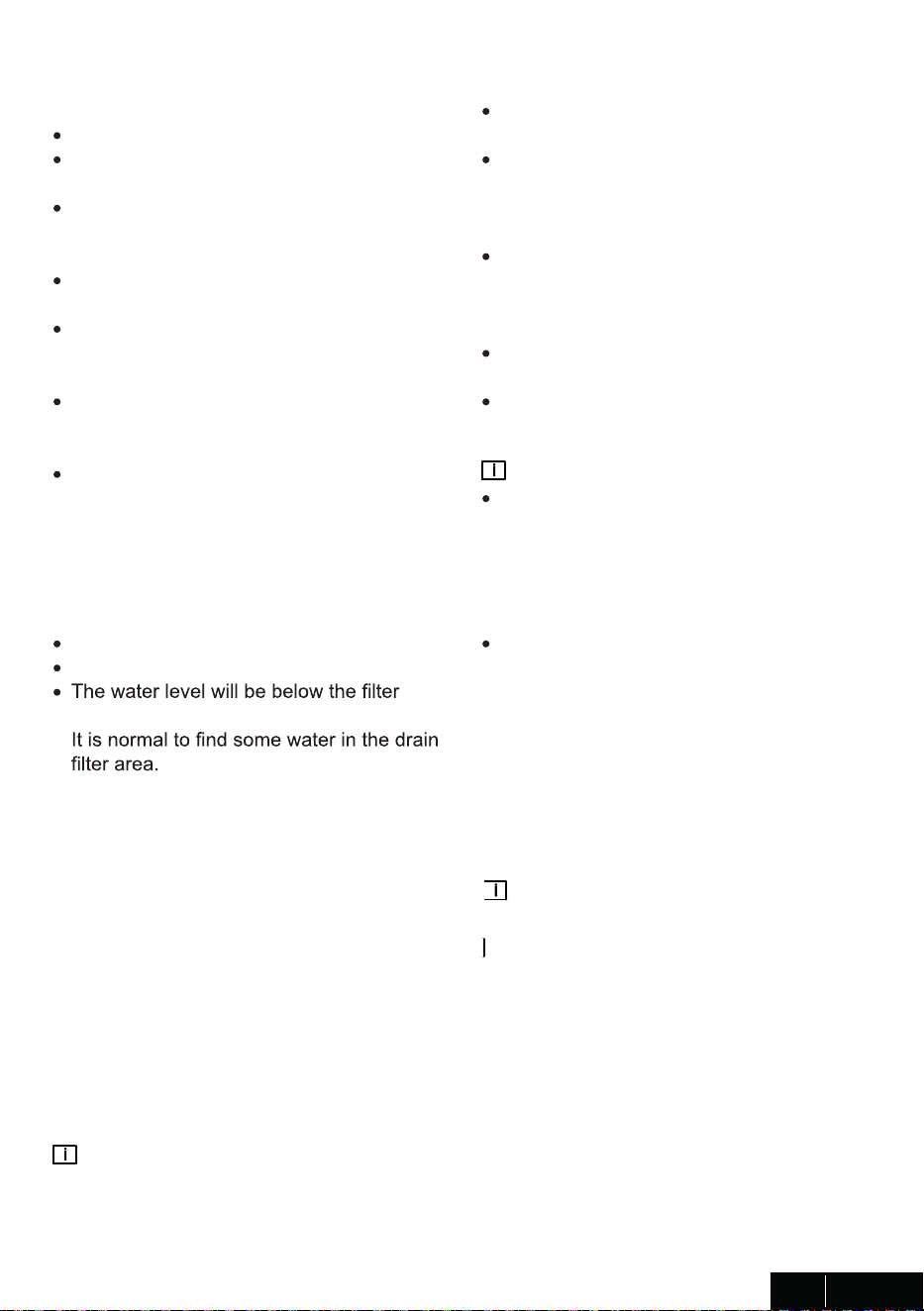
8. INSTALLER CHECKLIST
Your �nstaller must have completed and
checked the follow�ng:
The d�shwasher �s square and level.
The d�shwasher �s fastened securely to the
cab�netry.
The d�shwasher door opens and closes
freely. The d�shwasher door must close
w�thout h�tt�ng any cab�netry or counter top.
The �nlet water supply �s turned on and
checked for leaks.
The dra�n hose has been connected and
checked for leaks. There must be no k�nks
or obstruct�ons �n the dra�n hose.
The dra�n hose must be �nstalled w�th a 28"
(710mm) h�gh dra�n loop for dra�n hook-ups
w�thout any a�r removed.
If you connect the water dra�n hose to a
trap sp�got under the s�nk, remove the
plast�c membrane. If you do not remove
the ent�re membrane, rema�n�ng food can
cause a blockage �n the dra�n hose sp�got.
Ensure a hose clamp �s used to secure the
hose to the sp�got.
The spray arms are free and rotate freely.
The r�nse cycle has been run.
screen after the end of the wash program.
9. FINAL INSTRUCTIONS
1. Press the On/Off button to turn the
d�shwasher on.
2. Power �nd�cator l�ght comes on.
3. Use the Program Select button to choose
a wash�ng program.
4. Start the program w�th the Start/Pause/
Cancel button.
5. Run the d�shwasher through one complete
cycle. When the wash cycle �s completed,
use the On/Off button to turn the d�shwasher
off.
Not�ce :
If the d�shwasher does not operate properly,
refer to the self help h�nts.
10. SELF HELP HINTS:
The screen does not come on:
Check to make sure the breaker to the
d�shwasher �s �n the on pos�t�on.
Check to make sure that the Supply cord
�s plugged �n.
No Water �s com�ng �nto the d�shwasher:
Check to make sure the water shut-
off �s �n the ON pos�t�on.
Water does not dra�n:
Make sure dra�n hose �s not k�nked or
comes out of a�r gap next to the s�nk.
Remove dra�n hose from d�sposal mak�ng
sure plug �s removed.
Not�ce :
If your d�shwasher �s not operat�ng
properly after follow�ng these steps:
Contact your dealer to schedule an
author�zed serv�ce agent to �nspect your
new d�shwasher for any funct�on related
fa�lure.
The manufacturer warranty does not
cover �nstallat�on, convers�on or customer
educat�on serv�ce v�s�ts.
You w�ll f�nd the model and ser�al number
�nformat�on on the label located on the
r�ght-hand s�de of the �nner door of your
d�shwasher, as shown above.
Not�ce :
Please make a copy of your �nvo�ce and
keep �t w�th th�s manual and reg�ster your
d�shwasher on-l�ne.
18
USA / CAN