REV L DATE: 07/26/2023
USER MANUALS\20-17518_FUSION_USER MANUAL_GHSS(L)(H)HLB_HTD SHELVING-DECK_SELF-SVC_CASE
Note: See Next Page For Partial List Of
Models That This Manual Is Applicable To.
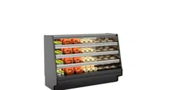
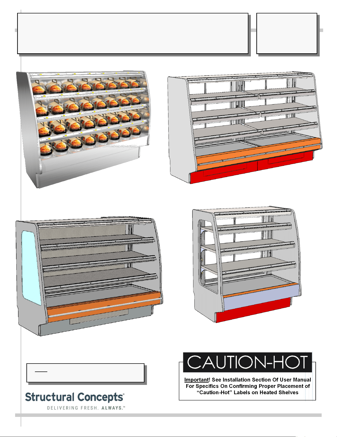
FUSION HEATED SHELVING, SELF-SERVICE 55 1/4”, 60” and 66 1/4” TALL MERCHANDISERS
Standard 3-Shelf Model GHSS460H (Shown
Stocked For Illustrative Purposes Only)
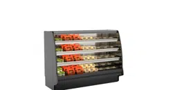
Standard 3-Shelf Model GHSS656HLB
(With Stainless Steel Front Bumper)
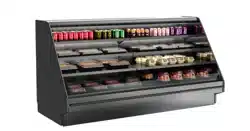
Standard 3-Shelf Model GHSS856HLB
(With Stainless Steel Front Bumper)
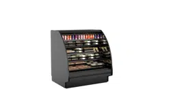
Standard 3-Shelf Model GHSS456HLB
Optional Controls Placement (Either Front or Rear)
With LEDs (Instead of Incandescent Lights)
SCC P/N
20-17518
USER
MANUAL
FUSION
CAREFULLY FOLLOW THESE INSTRUCTIONS
Structural Concepts Corp. ∙ 888 E. Porter Rd ∙ Muskegon, MI 49441 Phone: 231.798.8888 Fax: 231.798.4960 ∙ www.structuralconcepts.com
2
TABLE OF CONTENTS
OVERVIEW / TYPE / COMPLIANCE / WARNINGS / PRECAUTIONS / WIRING / PLUGS .............…..
INSTALLATION: SKID REMOVAL / FRAME SUPPORT RAIL SHIMMING / LEVELER
ADJUSTMENTS ..………………………….…………………………………..…………………..…….
INSTALLATION, CONT’D: FIELD ACCESS WIRING CONNECTIONS/ SWITCHES /
THERMOMETERS …...………………………………………………………………………………….
INSTALLATION, CONT’D: IMPORTANT! HEATED SHELF “DANGER - HOT” LABEL PLACEMENT
REMOVING VERTICAL LOWER FRONT (OR REAR) PANELS …………………………………………..
START-UP, OPERATION & SHUTDOWN - MODEL GHSS460H & GHSS656HLB 3-SHELF UNITS
(FRONT ACCESS UNITS) / AUTHORIZED PERSONNEL ONLY! ..………………………………
START-UP & OPERATION - MODEL GHSS456HLB (REAR ACCESS UNIT) - AUTHORIZED
PERSONNEL ONLY! ..……………………………………………………………………………………
START-UP & OPERATION - MODEL GHSS460HLB 3-SHELF UNIT (FRONT ACCESS UNIT)
AUTHORIZED PERSONNEL ONLY! ..………………………………………………………………..
START-UP & OPERATION - MODEL GHSS660H 4-SHELF UNIT (FRONT ACCESS UNIT)
AUTHORIZED PERSONNEL ONLY! …………………………………………………………………
DOOR REMOVAL (OPTIONAL) / DECK, SHELVING, OVERHEAD DIFFERENTIATION ………...…...
INCANDESCENT LAMP FIXTURES / REPLACEMENT GUIDELINES ……….…………………………..
OPTIONAL LED LIGHTS / SWITCH / LED LIGHT FIXTURES / LED REMOVAL and
REPLACEMENT ………………………………………………………………………………………...
VAPOR THERMOMETER ……………………………………………………………………………………….
CLEANING SCHEDULE (DAILY / WEEKLY) - CASE EXTERIOR .………………………….……..……..
CLEANING SCHEDULE (DAILY / WEEKLY) - CASE INTERIOR ………………………………………....
CLEANING SCHEDULE (DAILY / WEEKLY) - CASE EXTERIOR & INTERIOR: STAINLESS STEEL
TROUBLESHOOTING ….…………………………………………………..………………...…………..……..
SERIAL LABEL & LOCATION / TECHNICAL INFORMATION / ADD’L INFORMATION ……..……….
PROGRAMMABLE CONTROLLER (SELECT, CLICK ON OR SCAN QR CODE FOR INFO)…………
TECHNICAL SERVICE CONTACT INFORMATION / WARRANTY INFORMATION ..…….………........
3-4
5
6
7
8
9
10
11
12
13
14
15
16
17
18
19
20
21
22
23
This Manual Is Applicable To The Following Models*
GHSS452HLB / GHSS456HLB / GHSS460H / GHSS460HLB / GMSS467H / GMSS667H
GMSS867H / GHSS652HLB / GHSS656HLB / GHSS660H / GHSS856HLB
*This Manual May Be Applicable To Models Not Listed Above or Herein.
3
OVERVIEW
• These Structural Concepts cases should be installed and
operated according to these instructions to ensure proper
performance. Improper use will void warranty.
• This unit is designed to display products in ambient store
conditions with a maximum temperature of 80 °F (27 °C) .
DRY HEAT PURPOSES / PRE-HEATING PRODUCT, ETC.
This case is designed for dry heating operations throughout the
product area. Heat is generated from heated shelving/deck.
• Structural Concepts® heated merchandisers are designed
for packaged foods at 140 °F to 165 °F (60 °C to 74 °C).
• Product must be pre-heated to these temperatures PRIOR
TO being places in merchandiser. This case is NOT
designed to heat product from cold or ambient conditions.
• This merchandiser is designed to display perishable,
packaged products. Improper use will void warranty.
• Depending upon model, overhead incandescent lamps
may be used on shelving and header of merchandiser.
COMPLIANCE
This equipment MUST be installed in compliance with
all applicable NEC, federal, state and local
electrical and plumbing codes.
WARNING
Shelves and decks are hot!
Disconnect and allow to cool 45 minutes before cleaning,
servicing or removing from case.
WARNING
HOT
SURFACE
OVERVIEW / TYPE / COMPLIANCE / WARNINGS / PRECAUTIONS / WIRING / PLUGS - PAGE 1 of 2
INTEGRATED AVERAGE PRODUCT TEMPERATURE
• These units are designed to merchandise product at an
integrated average product temperature of 150 °F (66 °C).
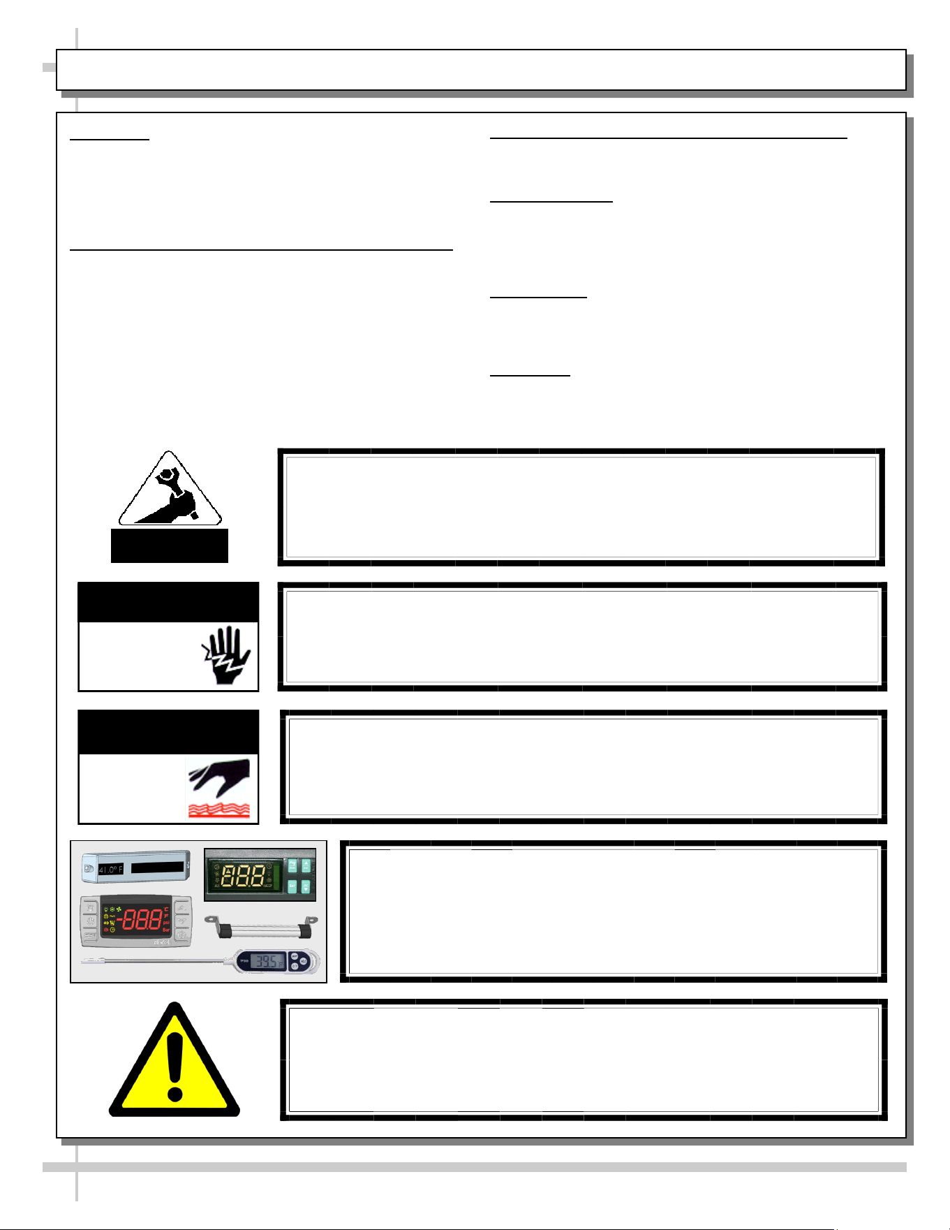
THERMOMETERS
• Thermometers in equipment reflect internal air temperature
only (not actual food temperature).
• Use probe thermometers to determine actual product
temperatures.
COMPLIANCE
• Performance issues when in violation of applicable NEC,
federal, state and local electrical and plumbing codes are
not covered by warranty. Please see below.
WARNINGS
• This page contains important warnings to prevent injury or
death. Please read carefully!
ATTENTION
CONTRACTORS
WARNING
This product can expose you to chemicals, including
Urethane (Ethyl Carbamate), which are known to the state of
California to cause cancer and birth defects or other reproductive
harm. For more information go to P65Warnings.ca.gov.
WARNING
Risk of electric shock.
Disconnect ALL ELECTRICAL SOURCES before servicing.
WARNING
ELECTRICAL
HAZARD
CAUTION! DO NOT RELY ON THERMOMETERS OR
THERMOSTATS FOR PRODUCT (FOOD) TEMPERATURES.
• Thermometers & thermostats reflect air temperatures ONLY.
• For ACTUAL product (food) temperatures, use a calibrated food
probe thermometers ONLY.
• For accurate readings, DO NOT use infrared food thermometers.
4
CAUTION! LAMP REPLACEMENT GUIDELINES
Incandescent lamps reflect specific size, shape and overall design.
Replacement lamps must be replaced with similar incandescent
lamps meeting the same factory specifications.
CAUTION
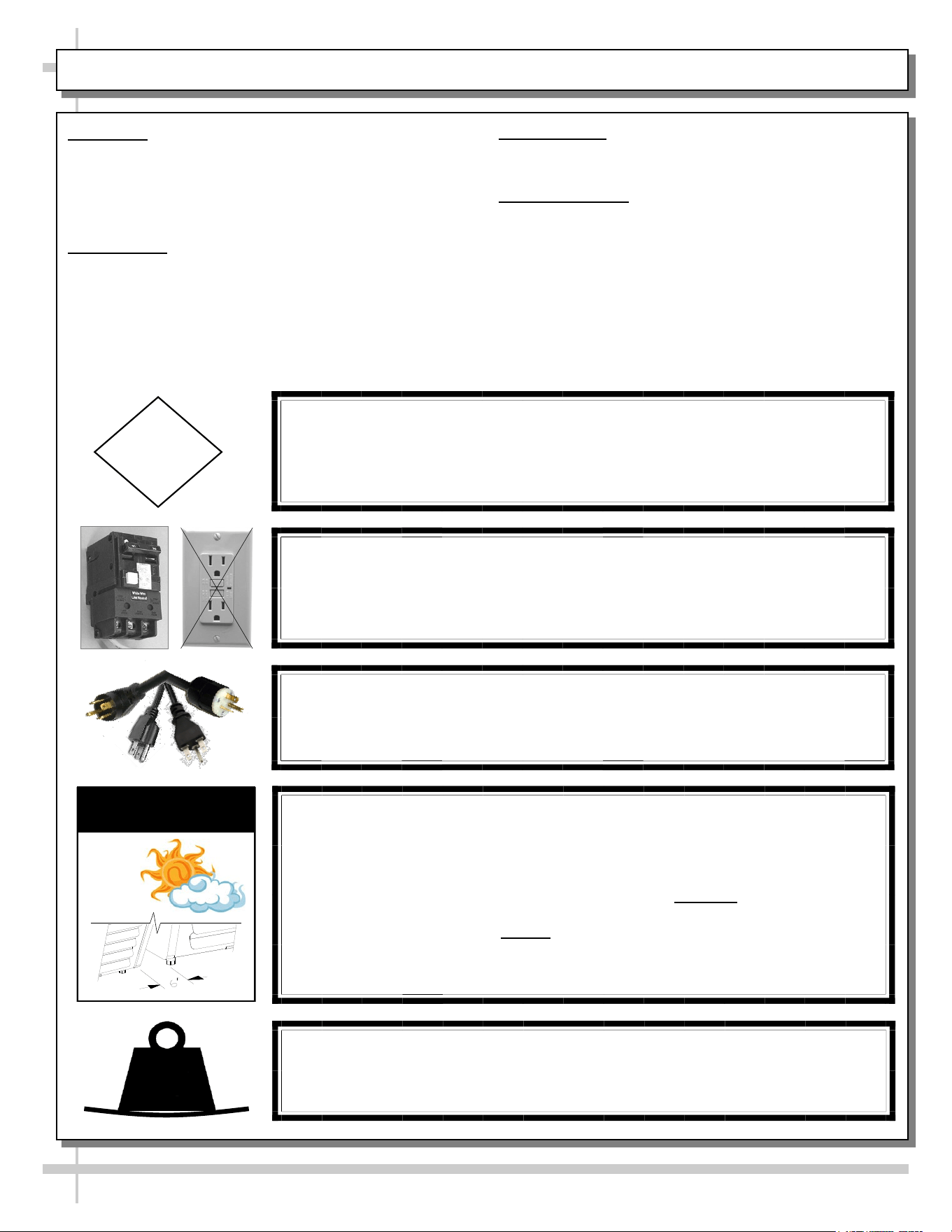
CAUTION! ADVERSE CONDITIONS / SPACING ISSUES
• Performance issues caused by adverse conditions are NOT covered
by warranty.
• End panels must be tightly joined or kept at least 6-inches away from any
structure to prevent condensation.
• Unit must be kept at least 15-feet from exterior doors, overhead HVAC vents
or any air curtain disruption to maintain proper temperatures.
• Do not expose to direct sunlight or heat source (ovens, fryers, etc.).
CAUTION
CAUTION! POWER CORD AND PLUG MAINTENANCE
Risk of electric shock. If cord or plug becomes damaged,
replace only with cord and plug of same type.
OVERVIEW / TYPE / COMPLIANCE / WARNINGS / PRECAUTIONS / WIRING / PLUGS - PAGE 2 of 2
CAUTION! GFCI BREAKER USE REQUIREMENT
If N.E.C. (National Electric Code) or your local code
requires GFCI (Ground Fault Circuit Interrupter) protection,
you MUST use a GFCI breaker in lieu of a GFCI receptacle.
OVERVIEW
• These Structural Concepts cases should be installed and
operated according to these instructions to ensure proper
performance. Improper use will void warranty.
• This unit is designed to display of products in ambient
store conditions with a max. temperature of 80 °F (27 °C) .
COMPLIANCE
• Performance issues when in violation of applicable NEC,
federal, state or local electrical codes are not covered by
warranty. See below.
PRECAUTIONS
• Following are important precautions to prevent damage
to unit or merchandise. Please read carefully!
WIRING DIAGRAM
• Each case has its own wiring diagram folded and in its
own packet. It may be placed near ballast box, field
wiring box, raceway cover, or other related location.
CAUTION!
• Cases with glass enclosures: To prevent sagging or breakage, do not exceed
5 LBS (2.3 KG) weight load per top glass section (between vertical supports).
• To prevent scratching or marring, do not place ANY items on glass.
5
LBS
5
INSTALLATION: SKID REMOVAL / FRAME SUPPORT RAIL SHIMMING / LEVELER ADJUSTMENTS
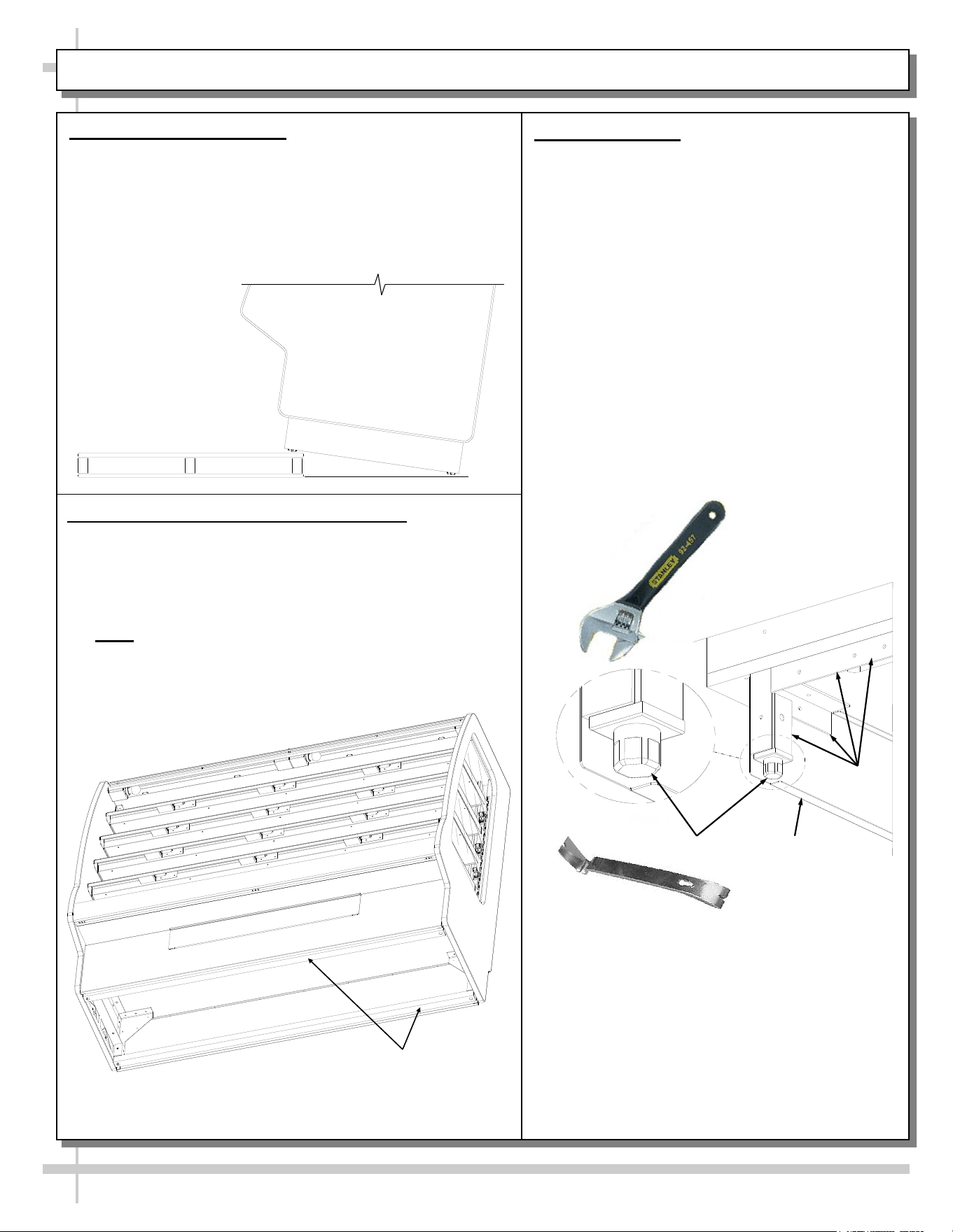
1. Remove Unit From Skid
• Caution: Case must always remain supported or
center of gravity will allow case to fall.
• Slide unit to rear of skid and lean backward off skid.
• Slide skid out from under case while case is being
supported.
Pry Bar
Toe-Kick
Base
Frame
Leveler
Adjustable
Wrench
3. Adjust Levelers
• Some cases have levelers. If so, after case
is in proper position, adjust case so it is
level and plumb (see illustration below).
• You may need to remove front and/or rear
Toe-Kick to access levelers.
• Use adjustable wrench to adjust leveler.
• Depending upon case weight it may be
necessary to use a pry bar to accomplish
this task.
• Do not use pry bar on toe-kick as it may
buckle.
• Do not use pry bar on end panel as it may
chip.
• Use pry bar ONLY on base frame to avoid
damaging case.
• See illustration and photo below.
2. Frame Support Rails Must Be Shimmed
• Most cases have frame support rails (shown below).
• Shims will be provided with all cases that have frame
support rails. Use shims to level case.
• You may need to remove front and/or rear toe-kick to
access levelers
• Note: After case is in position, it must be sealed to
floor to prevent entry or leakage of liquid or
moisture.
Frame Support
Rails
6
INSTALLATION, CONT’D: FIELD ACCESS WIRING CONNECTIONS/ SWITCHES / THERMOMETERS
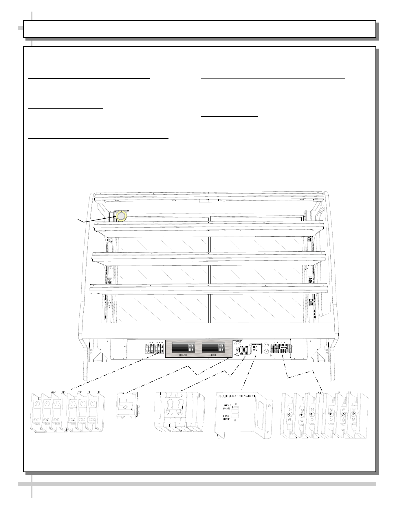
Gain access to field wiring / electrical raceway by
removing front panel (removal of screws is required).
4. Field Access Wiring Connections
Field wiring connection location is at customer-right,
at underside of raceway (as shown below).
5. Lamp Power Switch
• Lamp switch is at customer-right.
• One (1) lamp switch controls all bulbs in unit.
6. Single vs. Three-Phase Selector Switch
• Both single phase field wiring leads AND three
phase field wiring leads are provided.
• Phase selector switch (see location below) must
match field wiring.
• Note: Depending upon options chosen, phase
selector switch lockout bracket may be standard.
Lamp
Switch
Terminal Block
Phase Selector Switch
(1-Phase vs. 3-Phase)
Terminal Block
50-Amp
4-Pole Lever
Main Power Switch
If not, optional phase selector switch lockout
bracket (SCC P/N 20-35413) is available.
7. 50-Amp 4-Pole Lever Main Power Switch
• See illustration below.
• Power to all lights AND heated shelves is shut off
when this switch is turned off.
8. Thermometers
• Thermometers in equipment reflect internal air
temperature only (not actual food temperature).
• Use probe thermometers to determine actual
product temperatures.
• See Vapor Thermometer section in manual for
temperature dial design and range.
Vapor
Thermometer
7
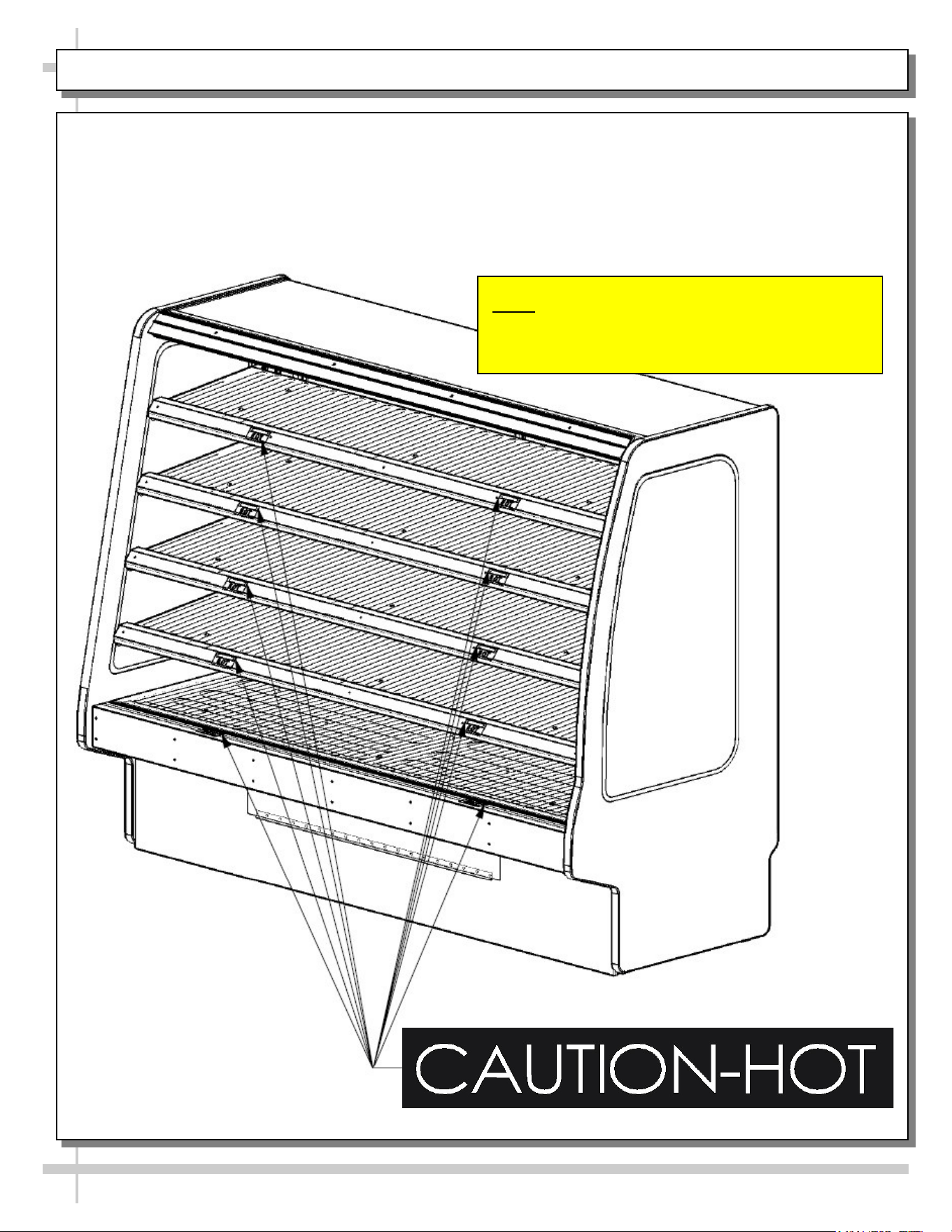
INSTALLATION, CONT’D: IMPORTANT! HEATED SHELF “DANGER - HOT” LABEL PLACEMENT
9. Important! Check That “Danger - Hot” Labels Are Properly Attached To Case.
• Shelves can get extremely hot and cause severe burns.
• Illustration below shows proper placement of “Danger - Hot” Labels.
• Two labels must be placed on each shelf and lower panel (as shown below).
• If labels are not properly attached, contact Structural Concepts regarding label P/N 20-11836.
• See SCC TECHNICAL SERVICE CONTACT INFORMATION section in manual for contact information.
Note: Illustrations Shown May Not Exactly
Reflect Every Feature Or Option Of
Your Particular Case.
8
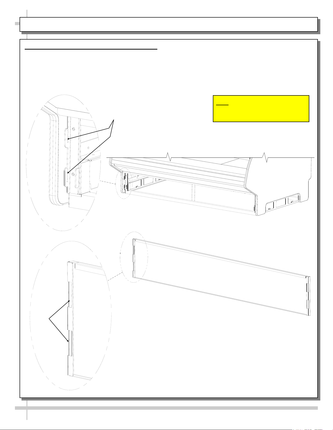
REMOVING VERTICAL LOWER FRONT (OR REAR) PANELS
Removing Vertical Lower Front (or Rear) Panel
• No screw removal is required to remove lower front
panel.
• Simply lift lower front panel slots up and off case
hooks.
Hooks
Lower Front Panel
(Reversed to Show Slots
Slots
• Replace in same manner it was removed.
• Illustrations shown may not exactly reflect every
feature or option of your particular case.
Note: Illustrations Shown May Not
Exactly Reflect Every Feature Or
Option Of Your Particular Case.
9
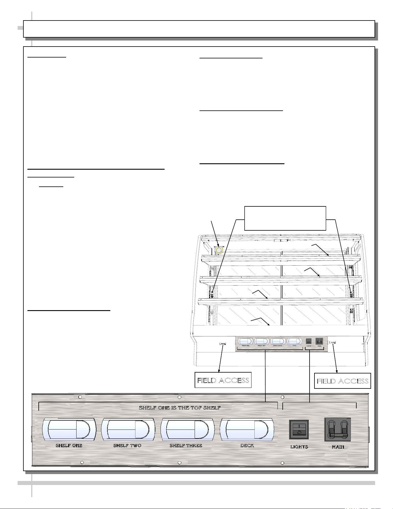
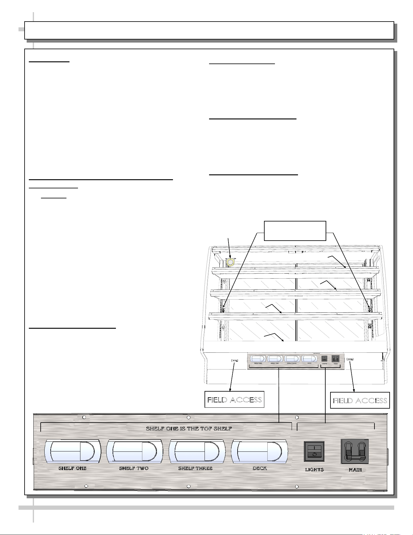
START-UP & OPERATION - MODEL GHSS460H / GHSS656HLB - AUTHORIZED PERSONNEL ONLY!
Deck
Shelf 3
Shelf 1
Shelf 2
Remove For Optional Fourth
Shelf (Not Applicable To
Model GHSS656HLB)
Vapor
Thermometer
4. Operating Tips
• When restocking, place new product at back and
rotate older product to front of case.
• Display product expected to sell within 4 hrs.
• Clean up residue immediately. Case will cause
spills and debris to harden to surface!
5. Shutting Down Case
• Remove all product from case.
• Turn main power switch to “OFF” position.
• Allow case to cool for 45 minutes before cleaning.
• See CLEANING SCHEDULE section in User
Manual for specific cleaning instructions.
6. Optional 4-Shelf Unit
• Case is wired for 4th shelf.
• Both receptacle and plug protective covers may
be removed by accessing two (2) screws.
1. Start-Up - Note: This Section Is For
Authorized Personnel Only!
• Control panel is at case front. It may be
accessed by removing front panel (no screw
removal required).
• Main power switch, lights switch and
thermostats are on control panel. Replace front
panel after energizing control panel
• Turn main power switch on to energize case
(heated deck, heated shelves and lights).
• Turn on light switch for case lights to come on.
• Caution! Deck, shelving and overhead lights
are HOT! Do not touch until case has been
turned off and allowed to cool for 45 minutes!
2. Pre-Cooking Food / Checking Food
Temperature
• Caution! Food MUST BE cooked PRIOR to
being placed in the case. Food should be
heated to between 150 °F to 160 °F (65.6 °C -
71 °C) prior to placing it in the case.
• All food products temps are to be at 140 °F to
165 °F (60 °C to 74 °C), for shelves and deck.
Food temperature must NOT be allowed to
be below FDA guidelines of 140 °F (60 °C).
• Use ONLY food probe to check product
temperature before placing it in case.
• DO NOT rely on case thermometer or infrared
thermometer gun!
• After product has been placed in case, check
product temperature (again) after one hour to
verify that proper food temperatures are
maintained.
3. Thermostat Settings
• Important! Default thermostat settings are
set at the factory. This case should rarely
require adjustments to thermostat settings.
• If thermostat settings need to be adjusted, see
PROGRAMMABLE CONTROLLER section in
this User Manual.
• If temperature is adjusted, allow 20 minutes
at NEW settings to determine if product
temperatures are acceptable.
• Check food temperature again after one hour.
OFF
ON
OFF
ON
10
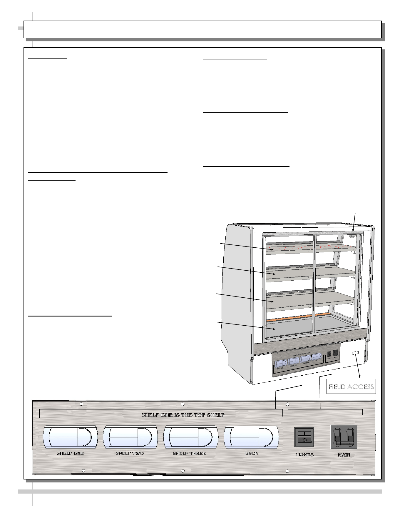
START-UP & OPERATION - MODEL GHSS456HLB (REAR ACCESS) - AUTHORIZED PERSONNEL ONLY!
Vapor
Thermometer
Deck
Shelf 1
Shelf 2
Shelf 3
OFF
ON
OFF
ON
1. Start-Up - Note: This Section Is For
Authorized Personnel Only!
• Control panel is at case rear. It may be fully
accessible or accessed by removing rear panel
(no screw removal required).
• Main power switch, lights switch and
thermostats are on control panel. Replace rear
panel after energizing control panel
• Turn main power switch on to energize case
(heated deck, heated shelves and lights).
• Turn on light switch for case lights to come on.
• Caution! Deck, shelving and overhead lights are
HOT! Do not touch until case has been turned
off and allowed to cool for 45 minutes!
2. Pre-Cooking Food / Checking Food
Temperature
• Caution! Food MUST BE cooked PRIOR to
being placed in the case. Food should be
heated to between 150 °F to 160 °F (65.6 °C -
71 °C) prior to placing it in the case.
• All food products temps are to be at 140 °F to
165 °F (60 °C to 74 °C), for shelves and deck.
Food temperature must NOT be allowed to
be below FDA guidelines of 140 °F (60 °C).
• Use ONLY food probe to check product
temperature before placing it in case.
• DO NOT rely on case thermometer or infrared
thermometer gun!
• After product has been placed in case, check
product temperature (again) after one hour to
verify that proper food temperatures are
maintained.
3. Thermostat Settings
• Important! Default thermostat settings are
set at the factory. This case should rarely
require adjustments to thermostat settings.
• If thermostat settings need to be adjusted, see
PROGRAMMABLE CONTROLLER section in
this User Manual.
• If temperature is adjusted, allow 20 minutes at
NEW settings to determine if product
temperatures are acceptable.
• Check food temperature again after one hour.
4. Operating Tips
• When restocking, place new product at back and
rotate older product to front of case.
• Display product expected to sell within 4 hrs.
• Clean up residue immediately. Case will cause
spills and debris to harden to surface!
5. Shutting Down Case
• Remove all product from case.
• Turn main power switch to “OFF” position.
• Allow case to cool for 45 minutes before cleaning.
• See CLEANING SCHEDULE section in User
Manual for specific cleaning instructions.
6. Optional 4-Shelf Unit
• Case is wired for 4th shelf.
• Both receptacle and plug protective covers may
be removed by accessing two (2) screws.
11
START-UP & OPERATION - MODEL GHSS460HLB (FRONT ACCESS) - AUTHORIZED PERSONNEL ONLY!
Deck
Shelf 3
Shelf 1
Shelf 2
Remove For Optional
Fourth Shelf
Vapor
Thermometer
OFF
ON
OFF
ON
1. Start-Up - Note: This Section Is For
Authorized Personnel Only!
• Control panel is at case front. It may be
accessed by removing front panel (no screw
removal required).
• Main power switch, lights switch and
thermostats are on control panel. Replace front
panel after energizing control panel
• Turn main power switch on to energize case
(heated deck, heated shelves and lights).
• Turn on light switch for case lights to come on.
• Caution! Deck, shelving and overhead lights are
HOT! Do not touch until case has been turned
off and allowed to cool for 45 minutes!
2. Pre-Cooking Food / Checking Food
Temperature
• Caution! Food MUST BE cooked PRIOR to be-
ing placed in the case. Food should be heated
to between 150 °F to 160 °F (65.6 °C - 71 °C)
prior to placing it in the case.
• All food products temps are to be at 140 °F to
165 °F (60 °C to 74 °C), for shelves and deck.
Food temperature must NOT be allowed to
be below FDA guidelines of 140 °F (60 °C).
• Use ONLY food probe to check product
temperature before placing it in case.
• DO NOT rely on case thermometer or infrared
thermometer gun!
• After product has been placed in case, check
product temperature (again) after one hour to
verify that proper food temperatures are
maintained.
3. Thermostat Settings
• Important! Default thermostat settings are
set at the factory. This case should rarely
require adjustments to thermostat settings.
• If thermostat settings need to be adjusted, see
PROGRAMMABLE CONTROLLER section in
this User Manual.
• If temperature is adjusted, allow 20 minutes at
NEW settings to determine if product
temperatures are acceptable.
• Check food temperature again after one hour.
4. Operating Tips
• When restocking, place new product at back and
rotate older product to front of case.
• Display product expected to sell within 4 hrs.
• Clean up residue immediately. Case will cause
spills and debris to harden to surface!
5. Shutting Down Case
• Remove all product from case.
• Turn main power switch to “OFF” position.
• Allow case to cool for 45 minutes before cleaning.
• See CLEANING SCHEDULE section in User
Manual for specific cleaning instructions.
6. Optional 4-Shelf Unit
• Case is wired for 4th shelf.
• Both receptacle and plug protective covers may
be removed by accessing two (2) screws.
12
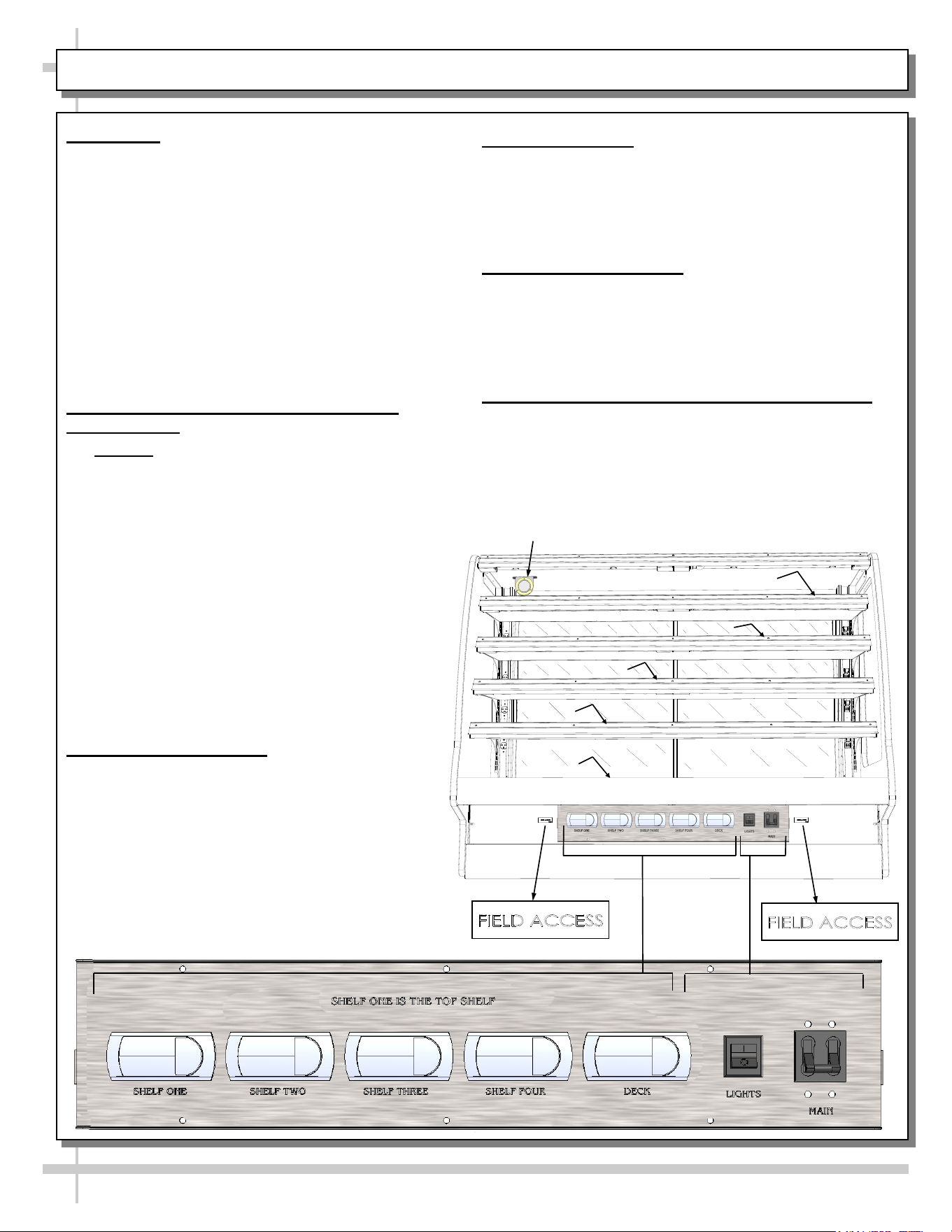
START-UP & OPERATION - MODEL GHSS660H (FRONT ACCESS) - AUTHORIZED PERSONNEL ONLY!
Deck
Shelf 3
Shelf 1
Shelf 2
Shelf 4
Vapor
Thermometer
1. Start-Up - Note: This Section Is For
Authorized Personnel Only!
• Control panel is at case front. It may be
accessed by removing front panel (no screw
removal required).
• Main power switch, lights switch and
thermostats are on control panel. Replace front
panel after energizing control panel
• Turn main power switch on to energize case
(heated deck, heated shelves and lights).
• Turn on light switch for case lights to come on.
• Caution! Deck, shelving and overhead lights are
HOT! Do not touch until case has been turned
off and allowed to cool for 45 minutes!
2. Pre-Cooking Food / Checking Food
Temperature
• Caution! Food MUST BE cooked PRIOR to be-
ing placed in the case. Food should be heated
to between 150 °F to 160 °F (65.6 °C - 71 °C)
prior to placing it in the case.
• All food products temps are to be at 140 °F to
165 °F (60 °C to 74 °C), for shelves and deck.
Food temperature must NOT be allowed to
be below FDA guidelines of 140 °F (60 °C).
• Use ONLY food probe to check product
temperature before placing it in case.
• DO NOT rely on case thermometer or infrared
thermometer gun!
• After product has been placed in case, check
product temperature (again) after one hour to
verify that proper food temperatures are
maintained.
3. Thermostat Settings
• Important! Default thermostat settings are
set at the factory. This case should rarely
require adjustments to thermostat settings.
• If thermostat settings need to be adjusted, see
PROGRAMMABLE CONTROLLER section in
this User Manual.
• If temperature is adjusted, allow 20 minutes at
NEW settings to determine if product
temperatures are acceptable.
• Check food temperature again after one hour.
4. Operating Tips
• When restocking, place new product at back and
rotate older product to front of case.
• Display product expected to sell within 4 hrs.
• Clean up residue immediately. Case will cause
spills and debris to harden to surface!
5. Shutting Down Case
• Remove all product from case.
• Turn main power switch to “OFF” position.
• Allow case to cool for 45 minutes before cleaning.
• See CLEANING SCHEDULE section in User
Manual for specific cleaning instructions.
6. Optional 4-Shelf Unit (Shown In This Unit)
• Case is wired for 4th shelf.
• Both receptacle and plug protective covers may
be removed by accessing two (2) screws.
13
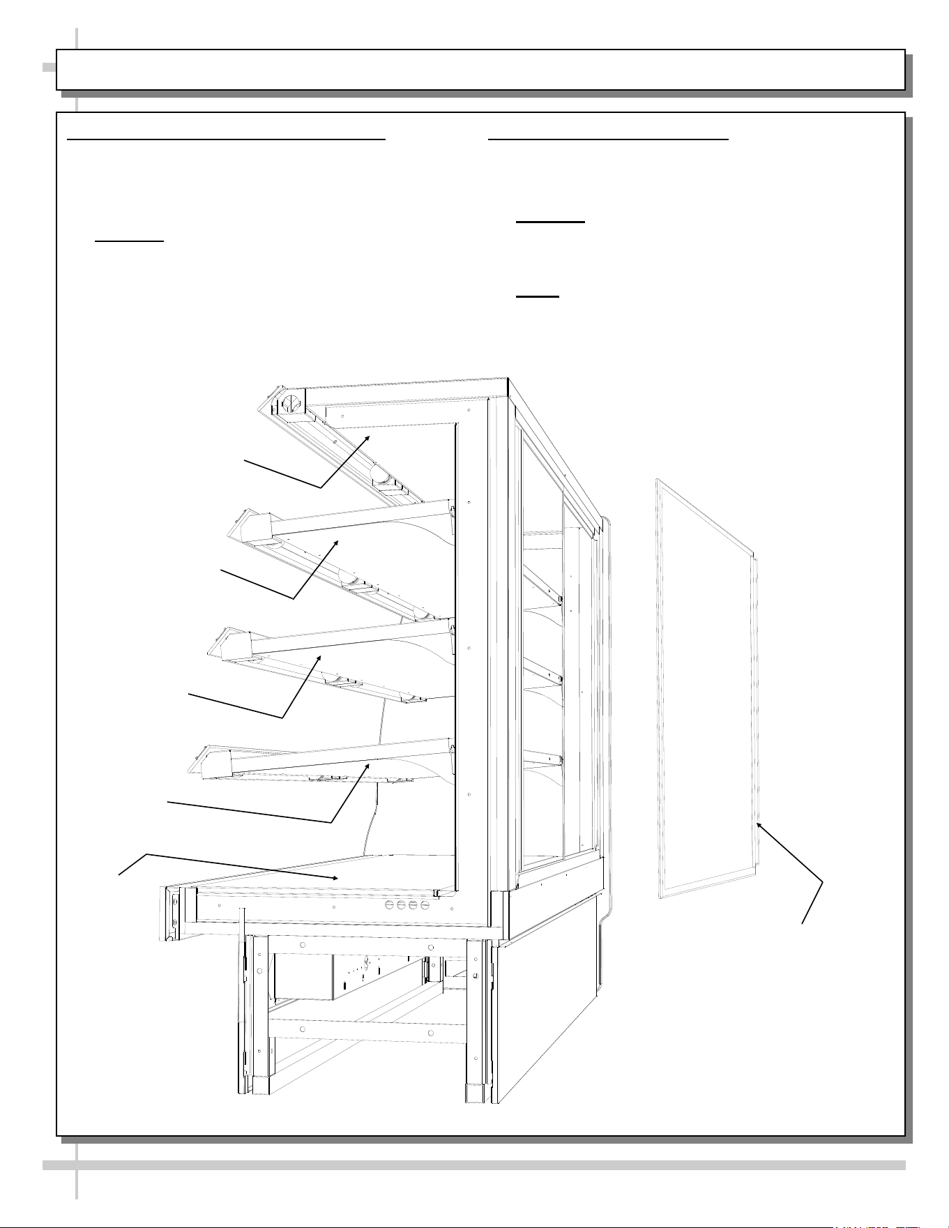
DOOR REMOVAL (OPTIONAL) / DECK, SHELVING, OVERHEAD DIFFERENTIATION
1. Removing The (Optional) Rear Doors
• See illustration below.
• Move rear doors toward the center of case.
• Individually lift each door up toward the top of
case and pivot bottom of the door out.
• Caution! Gently set doors down to avoid
marring, scraping, scratching or breakage.
View of Rear Door
(Optional) Being
Removed
Overhead
Shelf 1
Shelf 2
Shelf 3
Deck
2. Overhead, Shelving & Deck
• See illustration below for location of each.
• Temperature settings may vary between
overhead, shelving and deck.
• Caution! Surfaces are very hot! Before
servicing or cleaning make certain temperature
control settings are turned completely off and
case is allowed to cool for 45 minutes.
• Note: Illustration below reflects 3-shelf unit.
Depending upon options chosen, unit may have
four (4) shelves.
14
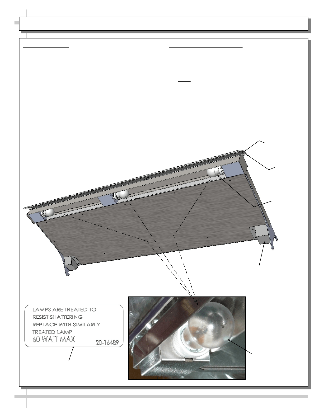
1. Lamp Fixtures
Removal of lamps:
• Caution! Lamps are extremely hot! urn off lamp
switch and allow to cool before removing lamps.
• Grasp lamp firmly; carefully unscrew from socket.
• See illustration below.
Installation of lamp:
• Grasp lamp firmly and carefully screw into socket.
• Turn on Lamp Switch.
• See illustration below
INCANDESCENT LAMP FIXTURES / REPLACEMENT GUIDELINES
Note 1: Depending
Upon Style and
Option Chosen,
Incandescent Bulb
Size and Shape
May Vary.
2. Replacement Guidelines
• Incandescent lamps reflect specific size, shape
and overall design.
• Any replacements must meet factory
specifications.
• Note: Labels are placed near each lamp.
Replace lamps ONLY with those specified.
• See illustration below-left for ACTUAL LABEL
that specifies allowable lamp replacements.
>> See next page for LED light fixture information.
Note: Labels Are Placed Near
Each Lamp. Replace Lamps
ONLY With Those Specified.
Heat
Shield
Label
Holder
Incandescent
Bulb (Typical)
Cover, Electrical
Connection (Typical)
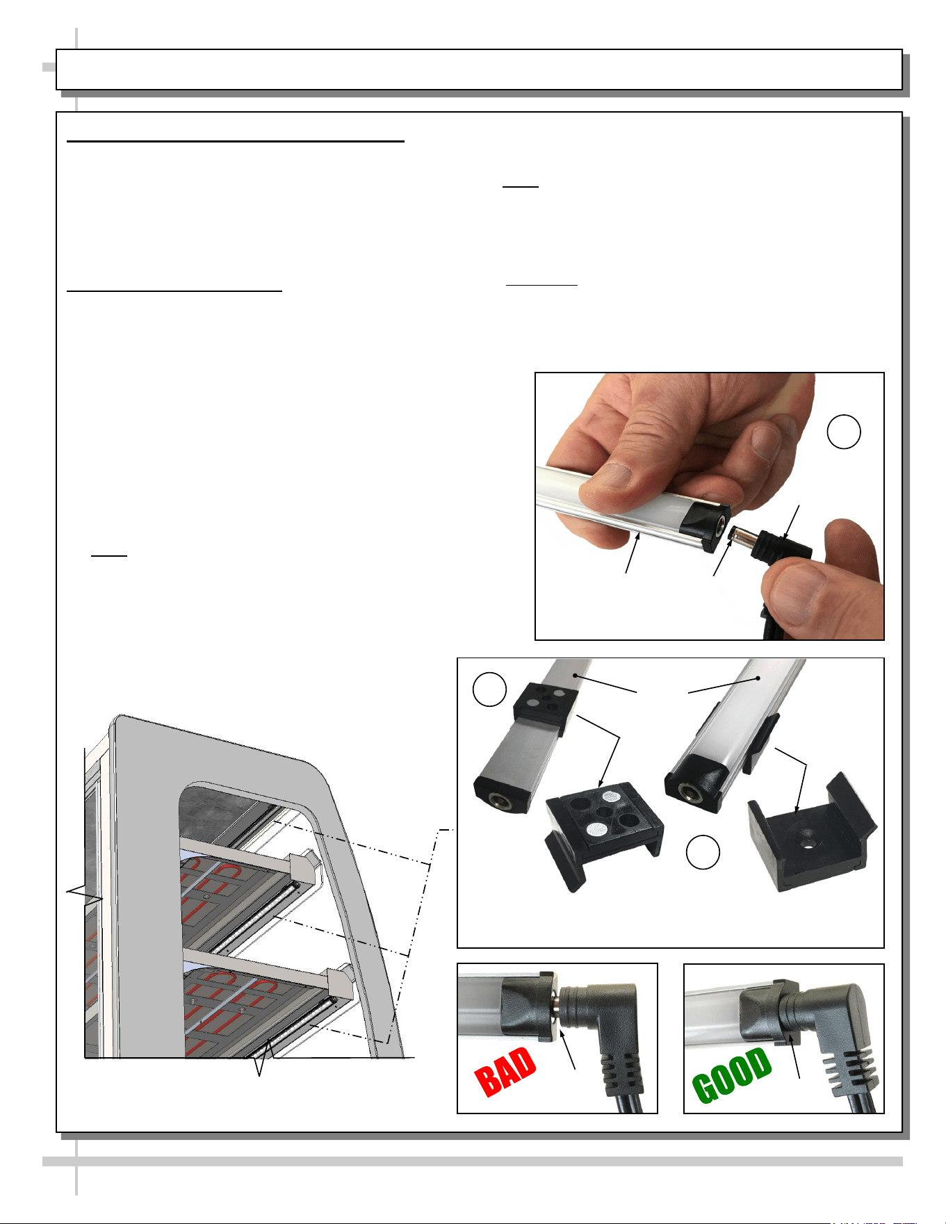
OPTIONAL LED LIGHTS / SWITCH / LED LIGHT FIXTURES / LED REMOVAL and REPLACEMENT
15
View of LED Lights At Underside of Header
and Shelving (On Certain Models)
A
Plug
Barrel
Shaped
Insert
LED
Light
Magnetic
Mounting Clip View #2
LED
Lights
B
C
Magnetic
Mounting Clip View #2
1. Optional LED Light Fixtures and Switch
• Light switch (that controls incandescent and
LED lights in same front panel as thermostats).
• Turning on incandescent lights will also turn on
LED lights.
• See STARTUP & OPERATION section for
general layout and light switch location.
2. LED Style Light Fixtures
Removal of Faulty LED Lights:
• LED lights rarely require change-out.
• Contact Structural Concepts’ Technical Service
Department for replacement LED lights.
• Turn off LED light switch.
• To remove faulty LED light, follow these steps:
A. Disconnect plug from LED light.
B. Using both hands, grasp LED light assembly
(with its magnetic mounting clips). Pull
downward and off its shelf (or header).
C. Remove magnetic mounting clips from LED
light by pressing against flange part of clip
with thumb.
>> Note: Mounting clips MAY be riveted to shelf or
header. In such instances, simply remove LED light
from mounting clips by pressing against flange part
of clips with thumb.
Replacement of LED lights:
• Attach magnetic mounting clips onto LED light.
• Adjust magnetic mounting clips so they are
equally spaced on LED light.
• Reattach LED light assembly to its shelf/header.
• Position properly in shelf/header.
>> Note: If mounting clips are riveted to shelf (or
header), attach by placing LED in base of clip and
then snapping into clip at FLANGE SIDE.
• Press plug’s barrel-shaped insert all the way into
LED light.
• Important: If plug is not inserted ALL THE WAY IN
the LED light’s orifice, the light may not energize.
See “BAD” vs. “GOOD” insertion illustrations
below-right.
• Turn LED light switch back on.
No Gap
Gap
16
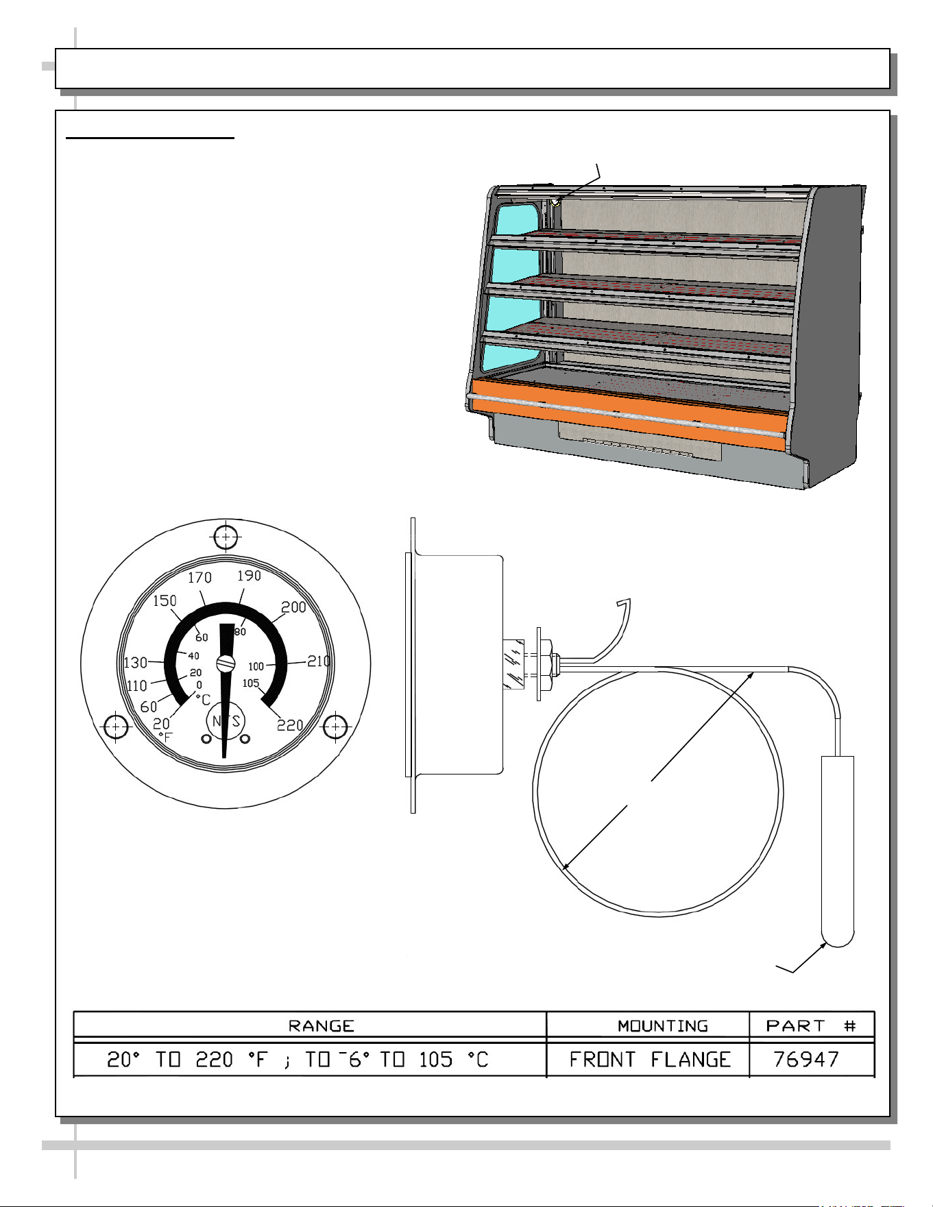
Vapor Thermometers
• Vapor thermometers in merchandisers reflect
internal air temperature only (not actual food
temperature).
• Temperature range is from 20 °F to 220 °F
(-6 °C to 105 °C)
• Use probe thermometers to determine actual
product temperatures.
• See view of random case at right for general
location of vapor thermometer.
• Illustrations below show dial design and
temperature range.
VAPOR THERMOMETER
General Location of
Vapor Thermometer
Vapor Thermometer
Front View
Vapor Thermometer
Side View
Temperature
Probe
Wire
17
CLEANING SCHEDULE (DAILY / WEEKLY) - CASE EXTERIOR
Cleaning Daily Weekly Task
Case
Exterior
X
Rear Sliding Glass Doors:
• Clean with a household or commercial glass cleaner.
X
Stainless Steel (Case Top, Sides, Front, Rear, Etc.):
• See CLEANING SCHEDULE (DAILY/WEEKLY) - CASE EXTERIOR &
INTERIOR: STAINLESS STEEL section in this operating manual.
X
Under Case Cleaning:
• Remove rear panel (8 screws) or front panel (2 screws).
• Clean under case with vacuum.
18
Caution! TURN MAIN POWER SWITCH TO “OFF”
and allow case to cool at least 45 minutes
before cleaning case interior!
Cleaning Daily Weekly Task
Case
Interior
X
Glass:
Clean inside surfaces of rear door and sides of case with a household or
commercial glass cleaner. Wipe dry with clean cloth or paper towel.
X
Polycarbonate Heat Shields (Above Each Shelf):
• Use a liquid detergent and clean with a clean cloth.
• Caution! Do not use glass cleaner on polycarbonate heat shields.
Such cleaning solution will cause heat shield to become cloudy and
crackled.
X
Stainless Steel (Case Top, Sides, Front, Rear, Etc.):
See CLEANING SCHEDULE (DAILY/WEEKLY) - CASE EXTERIOR &
INTERIOR: STAINLESS STEEL section in this operating manual.
X
Shelves and Decks:
Spills (Unhardened): Clean immediately to prevent hardening or “baking”
of spills. Use a dry cloth, folded over several times to clean up spills; this
will prevent being burned due to steam from wet cloth on the hot surfaces.
Spills (Hardened): Clean hardened spills with a damp cloth dipped in
household cleaner. For stubborn stains, use firm-bristled nylon brush or
scouring pad dipped in warm, soapy water. Use spray bottle with water
and clean paper towel to wipe up residue.
CLEANING SCHEDULE (DAILY / WEEKLY) - CASE INTERIOR
19
CLEANING SCHEDULE (DAILY/WEEKLY) - CASE EXTERIOR & INTERIOR: STAINLESS STEEL
General Stainless Steel Surface Cleaning (To Be Performed As Often As Needed):
• Certain grades of stainless steel, and some are more prone to corrosion than others.
• Stainless steel can become exposed to a wide variety of contaminants, which if left untreated can cause
stains and rust.
• Stainless steel requires a specific cleaning procedure to maintain its sheen and remain rust-free.
• Wash with a solution of liquid dishwashing detergent and hot water.
• Rinse with pure hot water from spray bottle. Wipe with clean sponge. This will remove soap residue
that can lodge in stainless steel’s microscopic grooves, causing rust.
• Dry with clean, soft cloth or paper towel.
• Caution! To prevent rust, you MUST rinse with pure hot water from a spray bottle while wiping with
clean sponge after EACH cleaning.
• Caution! Never clean with scouring powder or steel wool as they can mar, scratch and/or erode the
surface of stainless steel. When the surface properties of stainless steel have been compromised, rust
can form.
Brightening:
• Method 1: Brighten by polishing with a soft cloth or sponge with a solution of one part vinegar to 2 parts
water in a spray bottle.
• Method 2: Sprinkle baking soda on sponge and rub gently with soft cloth or sponge.
• Caution! To prevent rust, you MUST rinse with pure hot water from a spray bottle while wiping with
clean sponge after EACH cleaning.
• Dry with clean, soft cloth or paper towel.
Removing Streaks or Stains:
• Method 1: Place two teaspoons of rubbing alcohol on a microfiber cloth or pad. Rub the cloth along the
grain of the appliance until the entire area has been wiped. The rubbing alcohol will air dry itself.
• Method 2: Dip soft cloth or sponge in club soda and rub gently over area of concern.
• Caution! To prevent rust, you MUST rinse with pure hot water from a spray bottle while wiping with
clean sponge after EACH cleaning.
• Dry with clean, soft cloth or paper towel.
Polishing:
• Place a dab of olive oil onto clean soft cloth. Spread over area until a light sheen is observed. Use
pressure to “work the oil” into the small grooves in the surface. Apply firm, steady pressure using small
circular motions.
> Dry buff: Remove excess oil with clean cloth or paper towel using small circular motions.
> Wet buff: Use an ounce or white vinegar with clean cloth or paper towel using small circular motions.
> Continue wiping until oily finish has been removed.
• Caution! To prevent rust, you MUST rinse with pure hot water from a spray bottle while wiping with
clean sponge after EACH cleaning.
• Dry with clean, soft cloth or paper towel.
Removing Rust:
• If rust has begun to form, there are a variety of products that can treat it.
• Among these are CLR® (calcium, lime and rust remover) and Chemetall Oakite 33 (rust, oxides and
scale remover).
• Caution! To prevent food contamination, personal injury or further corrosion, carefully
observe and follow the rust removing product’s precautions and instructions.
20
CASE ISSUES TROUBLESHOOTING METHOD
Product is drying out Make certain that product has not exceeded allotted display time.
Authorized Personnel Only:
• Adjust temperature control settings. See START-UP, OPERATION AND
SHUTDOWN section for your model in this manual for instructions.
Product temperature
deviates outside of
acceptable range
(product either
overheating or too
cool)
• If deck or shelving contains few or no products, a temperature reading that is
outside of range may be experienced.
• When case is properly stocked, air is trapped between product; temperatures
should maintain proper range.
• Probe thermometer may be faulty. Use a stainless steel stem-type
thermometer with dial of at least a 1-inch internal diameter and test product.
Accuracy to within 1.8 °F / 1 °C is acceptable.
Authorized Personnel Only:
• Adjust temperature control settings: See START-UP, OPERATION AND
SHUTDOWN section for your model in this manual for instructions.
System is not
operating at all
Check that unit is properly plugged in.
Confirm that the MAIN power switch is on.
If power cord is used, confirm that it is plugged into outlet.
Authorized Personnel Only:
Confirm that the utility power is on.
Authorized Personnel Only:
Check the circuit breaker box for tripped circuits.
Authorized Personnel Only:
GFCI may be required. If N.E.C. (National Electric Code) or your local code
requires GFCI (Ground Fault Circuit Interrupter) protection, you MUST use a
GFCI breaker in lieu of a GFCI receptacle.
Product is not heating
at all
Heating elements may be malfunctioning.
• Call Structural Concepts Technical Service (at last page of this manual).
• Move product to separate location until unit is repaired.
Case lights are not
working
Caution! Case is extremely hot hot! Turn off main power switch and allow
case to cool for 45 minutes before touching light bulbs.
• Be sure ALL lights are screwed in properly.
• Check that bulbs are not burned out.
TROUBLESHOOTING
21
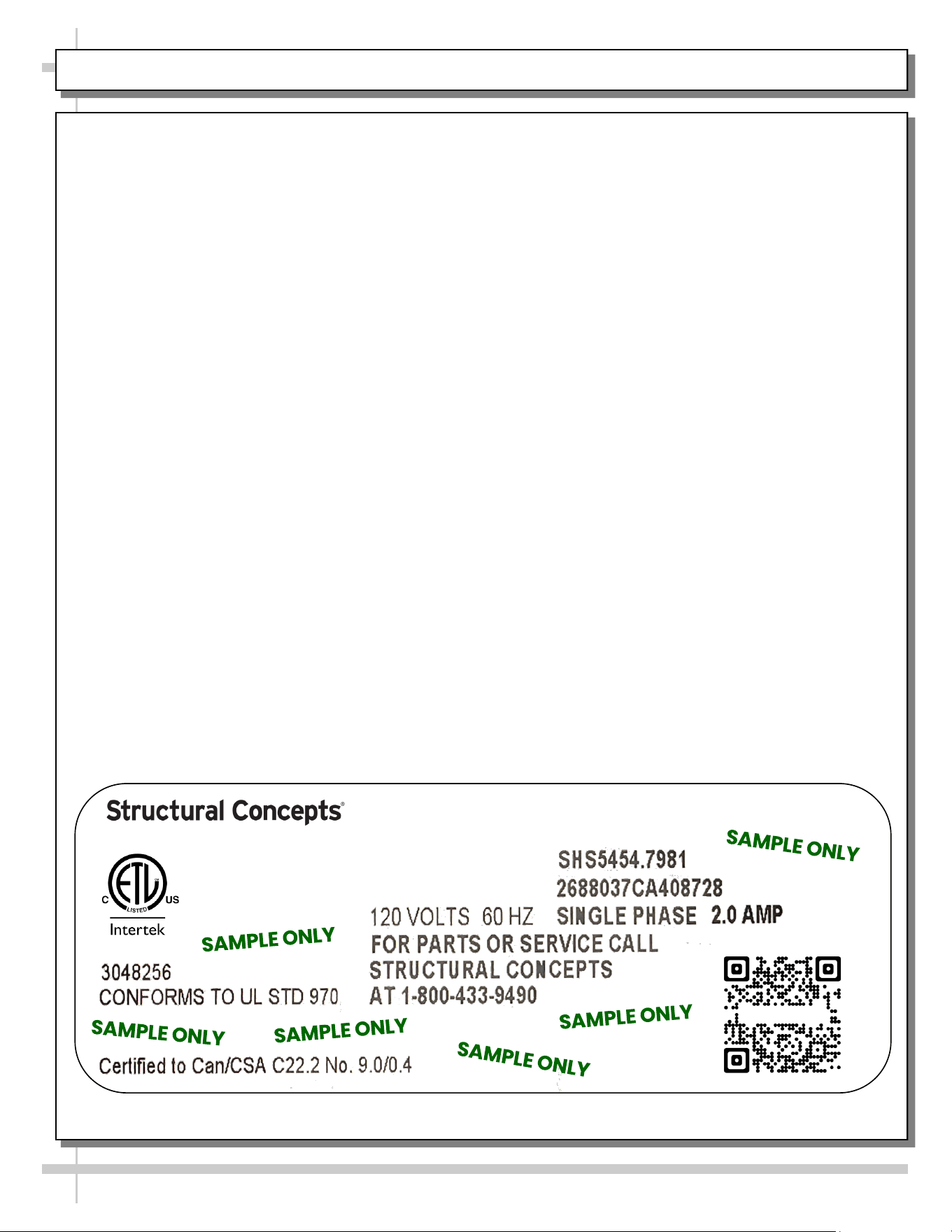
SERIAL LABEL LOCATION & INFO LISTED / TECH INFO & SERVICE - AMBIENT/HEATED CASES ONLY
Serial Label Location & Information Listed /
Technical Information & Service
• Serial labels are affixed at a wide range of places
(on the header, at case rear, behind panels or
toe-kicks, on electrical boxes, etc.).
• Serial labels contain electrical information as well
as regulatory standards to which the case
conforms.
• Sample serial label is shown. A variety of models is
displayed on serial label for illustration purposes only.
Your case’s serial label will reflect only one model.
• For additional technical information and service, see
the TECHNICAL SERVICE page in this manual for
instructions on contacting Structural Concepts’
Technical Service Department.
--- Sample Serial Label For Ambient/Heated Cases ---
888 E. Porter Rd - Muskegon, MI 49441
Sample QR Code
SCAN FOR PRODUCT LITERATURE
Reveal
Harmony
Impulse
Addenda
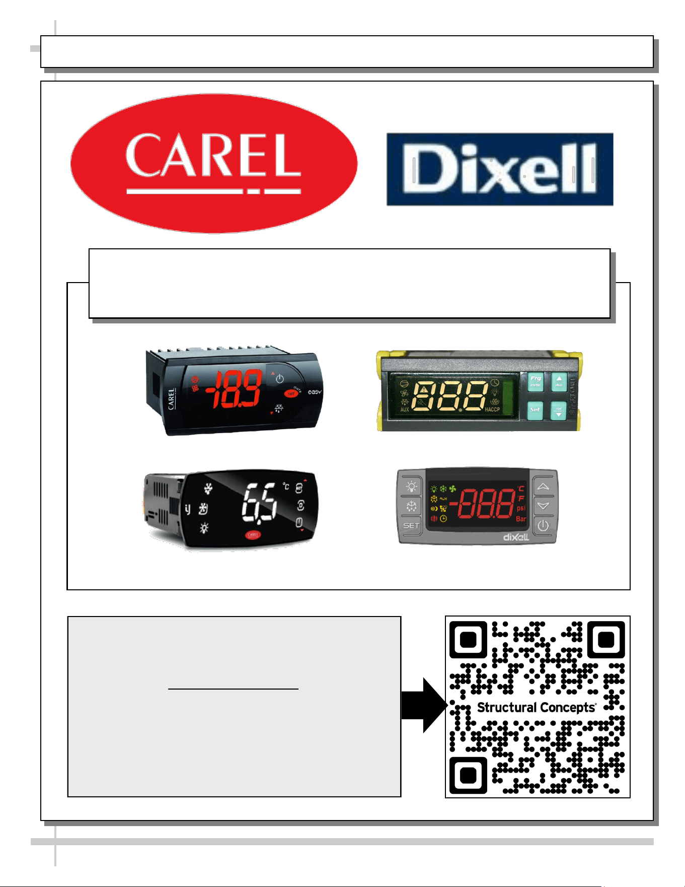
PROGRAMMABLE CONTROLLER (SELECT, CLICK ON OR SCAN QR CODE FOR INFORMATION)
22
Carel® iJF Platform
Carel® PJEZ Platform
Carel® ir33 Platform
Dixell® XM670K-XM679K Platform
To Access Information About The Programmable
Controller That Is Used On Your Case,
Follow These Instructions:
> If Viewing This Document on Smart Phone, Tablet
or Computer, Select/Click On The QR Code at Right.
> If Viewing This Document In Print (Hard Copy),
Scan The QR Code at Right With Your Smart Phone
or Tablet.
Determine Which Programmable Controller Is On Your Case (Controllers
That Are Commonly Used By Structural Concepts Are Shown Below).
Your Particular Programmable Controller May Differ.
STRUCTURAL CONCEPTS TECHNICAL SERVICE CONTACT INFORMATION & LIMITED WARRANTY
23
TECH SERVICE/WARRANTY CONTACT INFO:
1 (800) 433-9490 / EXTENSION 1
DAYS/HOURS AVAILABLE:
MONDAY - FRIDAY (CLOSED HOLIDAYS)
8:00 AM to 8:00 PM EST
YOU MUST HAVE THE FOLLOWING INFO AVAILABLE
BEFORE CONTACTING STRUCTURAL CONCEPTS:
SERIAL NO. / MODEL NO. / STORE NO. / STORE
ADDRESS / DETAILS (PHOTOS, LEAK LOCATIONS,
DAMAGE, STORE’S AMBIENT CONDITIONS, ETC.)
To Access The Limited Warranty To Your
Case, Follow These Instructions:
> If Viewing This Document on Smart Phone,
Tablet or Computer, Select/Click On The QR
Code at Right.
> If Viewing This Document In Print (Hard
Copy), Scan The QR Code at Right With Your
Smart Phone or Tablet.