REV AA DATE: 07/10/2023
USER MANUALS\20-01693_FUSION_USER MANUAL_GHSS(L)(H)RLB_GHSSAC_GHSSEH_REF_SELF-SVC_CASE
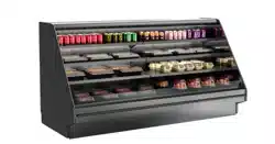
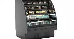
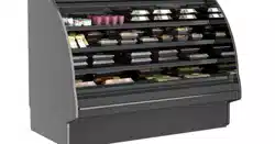
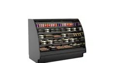
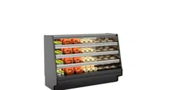
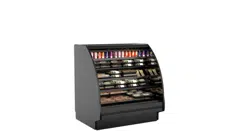
FUSION HIGH-VOLUME SELF-SERVICE REFRIGERATED DISPLAY CASES ||| NOTE: CASES SHOWN WITH FULL &
OPEN END PANELS AS WELL AS WITH STRAIGHT OR ANGLED BASES. YOURS MAY DIFFER.
GHDSS850R
GHSS652RLB Without
Right End Panel
GHSS660R w/Optional Perforated
Plexiglas® Sliding Doors
GHSS1075RLB.5422
GHSSAC652R
GHSSACS857R
Includes Scale Stand
GHSS656R / Optional Night
Air Curtain / Locking Security
Cover / Rear Sliding Doors
GHSS456R
Optional Night Air Curtain
& Locking Security Cover
GHBSS5R.4986A
(Remote)
GHSSEH656RLB (Remote)
GHSSFHX945RLB.6100E / 90°
Outside Wedge & Full Length Header
GHSS1252RLB.6796F
(With Rear Swinging Doors)
GHSSACS645RLB.6527
SCC P/N
20-01693
USER
MANUAL
FUSION
CAREFULLY FOLLOW THESE INSTRUCTIONS
Structural Concepts Corp. ∙ 888 E. Porter Rd ∙ Muskegon, MI 49441 Phone: 231.798.8888 Fax: 231.798.4960 ∙ www.structuralconcepts.com
GHSSVX452RLB
45° Outside Wedge
2
TABLE OF CONTENTS
TABLE OF CONTENTS ………………………………………………………………………………………...
OVERVIEW / TYPE 1 vs. 2 / COMPLIANCE / WARNINGS / PRECAUTIONS / WIRING / PLUGS …...
INSTALLATION: REMOVAL FROM SKID, REMOVING LOWER FRONT PANELS ..……...…….……..
INSTALLATION: ADJUSTING FRONT PANELS / ADJOINING UNITS / GLASS SHELVING ………….
INSTALLATION: ELECTRICAL CONNECTIONS / BALLAST BOX / LED DRIVER (REMOTE UNITS).
INSTALLATION: ELECTRICAL CONNECTIONS / BALLAST BOX / LED DRIVER
(SELF- CONTAINED UNITS) …….…………………………………………………………………....
INSTALLATION: UNDERSIDE FIELD ACCESS COMPONENTS (REMOTE MODEL
GHSSEH456RLB DISPLAYED) ……………………………………………………………………….
INSTALLATION: TOPSIDE FIELD ACCESS COMPONENTS AND TOPSIDE REFRIGERATION
LINE ROUTE (REMOTE MODEL GHSS675RLB.5422A DISPLAYED) ………………………….
INSTALLATION: ELECTRICAL CONNECTIONS / OPTIONAL SCALE STAND ………………………..
INSTALLATION, CONT’D: BASE FRAMES / SEALING TO FLOOR …………………………..………....
INSTALLATION, CONT’D: ADJUSTING LEVELERS ……………………………………………………….
INSTALLATION, CONT’D: CASTER STYLES / LOCKING & UNLOCKING / RAISING & LOWERING.
INSTALLATION: REFRIG. LINES / STUB-UPS / DRAINS / WIRING DIAGRAMS / VENTILATION …..
INSTALLATION: DISPLAY CASE START-UP (CASE / LIGHTS / TEMPERATURE CONTROLLER /
SATURATED SUCTION TEMPERATURE) ..………………………………………………………..
MAINTENANCE: STANDARD LIGHT FIXTURES / REMOVAL & REPLACEMENT …..………………..
MAINTENANCE, CONT’D: LED STYLE LIGHT FIXTURES / LED CLIPS / CONNECTIONS /
THERMOMETERS ………………………………………………...………………………………....…
MAINTENANCE: BRACKET RETAINER REMOVAL / SHELF ASSEMBLY REMOVAL / DRAIN / TXV
ACCESS ……………………………………………………………………………………………..…..
MAINTENANCE: REFRIGERATION PACKAGE ILLUSTRATION (FROM SELF-CONTAINED
MODEL GHDSS850R) ………………………………………………………………………………….
MAINTENANCE: REFRIGERATION PACKAGE ILLUSTRATION (FROM SELF-CONTAINED
MODEL GHSS660R) …………………………………………………………………………………...
MAINTENANCE: OPTIONAL SLIDING REAR DOORS / PERFORATED ACRYLIC PLENUM /
CONDENSER COIL FILTER ...……………………………………………………………….………..
MAINTENANCE: OPTIONAL NIGHT AIR CURTAIN ATTACHMENT & OPERATING INSTRUCTIONS .
MAINTENANCE: REAR SWINGING/HINGED DOORS (MODEL GHSS1252RLB.6796 ONLY) ……...
GENERAL CLEANING (TO BE PERFORMED BY STORE PERSONNEL) ………………..……...……..
TROUBLESHOOTING (TO BE PERFORMED BY STORE PERSONNEL) ..………..…….……….…….
GENERAL CLEANING (TO BE PERFORMED BY TRAINED SERVICE PROVIDERS ONLY) …...…...
TROUBLESHOOTING (TO BE PERFORMED BY TRAINED SERVICE PROVIDERS ONLY) ………...
TROUBLESHOOTING - CONDENSING SYSTEM (TO BE PERFORMED BY TRAINED SERVICE
PROVIDERS ONLY) ...................................................................................................................
TROUBLESHOOTING - EVAPORATOR SYSTEM (TO BE PERFORMED BY TRAINED SERVICE
PROVIDERS ONLY) ...................................................................................................................
PREVENTIVE MAINTENANCE (TO BE PERFORMED BY TRAINED SERVICE PROVIDER ONLY)...
HONEYCOMB AIR DIFFUSER REMOVAL/INSTALLATION (TO BE PERFORMED BY TRAINED
SERVICE PROVIDER ONLY) …..……………………………………………………………………..
SERIAL LABEL INFORMATION & LOCATION ..……………………………………...…....…………..…...
PROGRAMMABLE CONTROLLER INFORMATION ……..….………………………….………….……....
TECHNICAL SERVICE CONTACT INFORMATION / WARRANTY INFORMATION ….……….….........
2
3-4
5
6
7
8
9
10
11
12
13
14
15
16
17
18
19
20
21
22
23
24
25
26
27
28-30
31
32
33
34
35
36
37
3
OVERVIEW
• These Structural Concepts cases are designed to
merchandise packaged products at 41 °F (5 °C) or less
product temperatures (unless custom cases with wire
rack shelving).
• Product must be pre-chilled to 41 °F (5 °C) or less before
being placed in merchandiser.
• Cases should be installed and operated according to this
operating manual’s instructions to ensure proper
performance. Improper use will void warranty.
TYPE 1 vs. TYPE 2 CONDITIONS
This unit is designed for the display of products in ambient
store conditions where temperatures and humidity are
maintained within a specific range.
• Type 1 conditions: ambient conditions are to be 55%
max. humidity and 75 °F (24 °C) max. temperature.
• Type 2 conditions: ambient conditions are to be 55%
max. humidity and 80 °F (27 °C) max. temperature.
• If unsure if unit is Type 1 or 2, see tag next to serial label.
See SERIAL LABEL LOCATION & INFORMATION
LISTED / TECH INFO & SERVICE section in this manual
for sample serial labels).
COMPLIANCE
• Performance issues when in violation of applicable
NEC, federal, state and local electrical and plumbing
codes are not covered by warranty.
• See below compliance guideline.
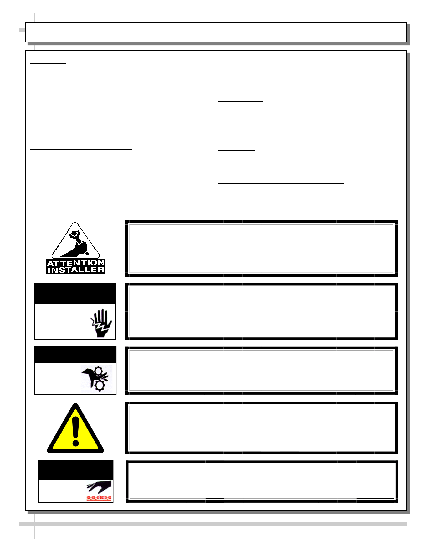
WARNINGS
• This page contains important warnings to prevent injury or
death. Please read carefully!
PRECAUTIONS and WIRING DIAGRAMS
• See next page for PRECAUTIONS and WIRING
DIAGRAM information.
WARNING
Hazardous moving parts. Do not operate unit with covers removed.
Fan blades may be exposed when deck panel is removed.
Disconnect power before removing deck panel.
WARNING
Risk of electric shock. Disconnect power before servicing unit.
CAUTION! More than one source of electrical supply is
employed with units that have separate circuits.
Disconnect ALL ELECTRICAL SOURCES before servicing.
WARNING
ELECTRICAL
HAZARD
WARNING
KEEP
HANDS
CLEAR
COMPLIANCE
This equipment MUST be installed in compliance with
all applicable NEC, federal, state and local
electrical and plumbing codes.
OVERVIEW / TYPE / COMPLIANCE / WARNINGS / PRECAUTIONS / CORDS / WIRING - PAGE 1 of 2
WARNING
This product can expose you to chemicals, including
Urethane (Ethyl Carbamate), which are known to the state of
California to cause cancer and birth defects or other reproductive
harm. For more information go to P65Warnings.ca.gov.
WARNING
Condensate pan and overflow condensate pans are HOT!
Disconnect and allow to cool before cleaning or removing from case.
WARNING
HOT
SURFACE
PRECAUTIONS
• Following are important precautions to prevent damage
to unit or merchandise. Read carefully!
• See previous page for specifics on OVERVIEW,
CONDITION TYPE, COMPLIANCE and WARNINGS.
WIRING DIAGRAM
• Each case has its own wiring diagram folded and in its
own packet. It may be placed near ballast box, field
wiring box, raceway cover, or other related location.
REFRIGERANT DISCLOSURE STATEMENT
• This equipment is prohibited from use in California with
any refrigerants on the “List of Prohibited Substances” for
that specific end-use, in accordance with California Code
of Regulations, title 17, section 95374.
• This disclosure statement has been reviewed and
approved by Structural Concepts and Structural Concepts
attests, under penalty of perjury, that these statements
are true and accurate.
OVERVIEW / TYPE / COMPLIANCE / WARNINGS / PRECAUTIONS / CORDS / WIRING - PAGE 2 of 2
4
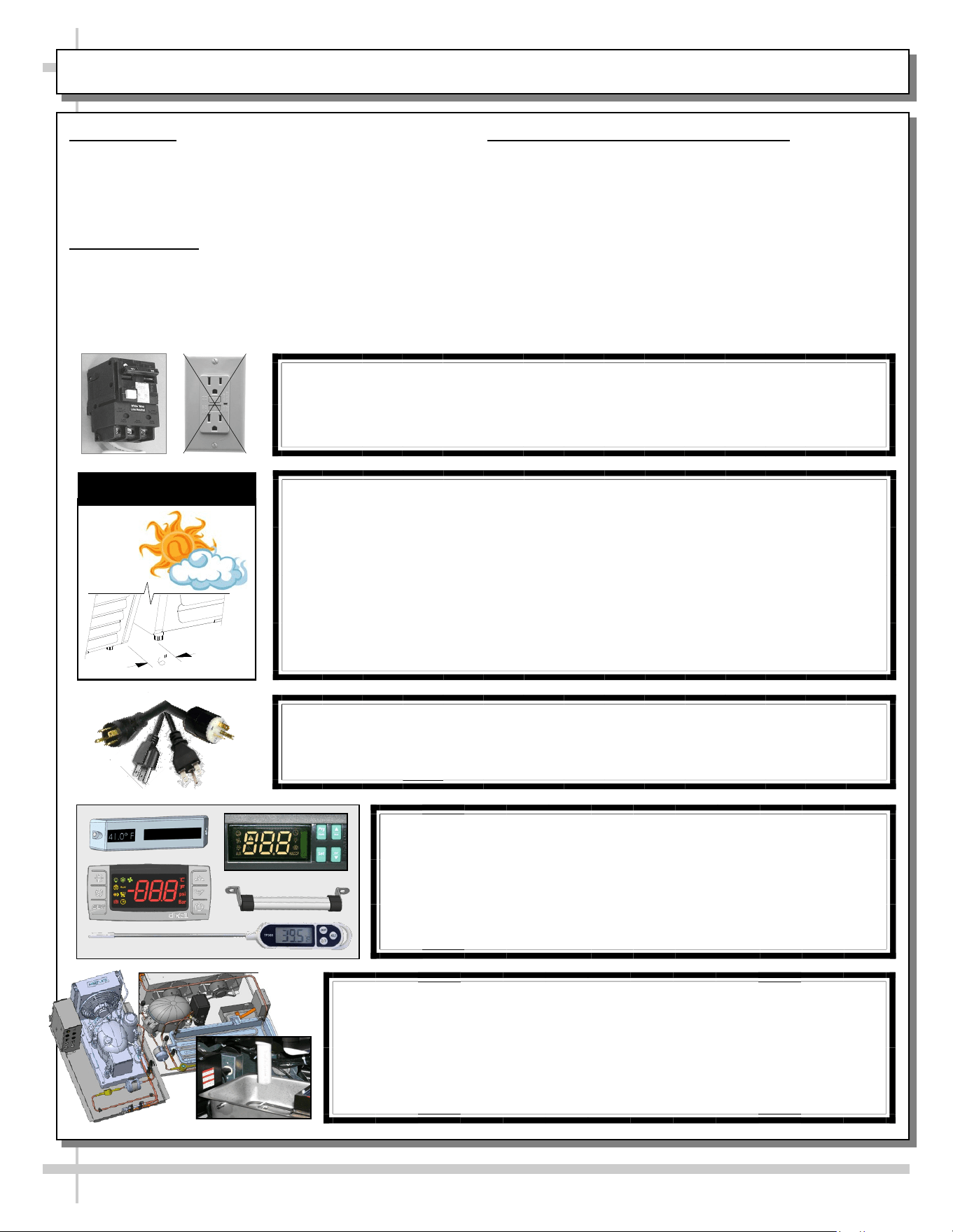
CAUTION! POWER CORD AND PLUG MAINTENANCE
Risk of electric shock. If cord or plug becomes damaged,
replace only with cord and plug of same type.
CAUTION! GFCI BREAKER REQUIREMENT
If N.E.C. (National Electric Code) or your local code
requires GFCI (Ground Fault Circuit Interrupter) protection,
you MUST use a GFCI breaker in lieu of a GFCI receptacle.
CAUTION! ADVERSE CONDITIONS / SPACING ISSUES
• Performance issues caused by adverse conditions are NOT warranted.
• To prevent damage to end panels due to condensation, apply industrial grade
silicone sealant and tightly join to opposite end panels. When not adjoining
cases, keep end panels at least 6” away from walls/structures. Rear panels
must also be kept at least 6” from walls and structures.
• Case must not be exposed to direct sunlight or any heat source.
• To maintain proper case temperature, keep case at least 15-feet from exterior
doors, overhead HVAC vents or any air curtain disruption.
• Self-contained case clearance: 6” min. air intake / 6” min. air discharge.
CAUTION
CAUTION! DO NOT RELY ON THERMOMETERS OR
THERMOSTATS FOR PRODUCT (FOOD) TEMPERATURES.
• Thermometers & thermostats reflect air temperatures ONLY.
• For ACTUAL product (food) temperatures, use a calibrated food
probe thermometers ONLY.
• For accurate readings, DO NOT use infrared food thermometers.
CAUTION! CHECK CONDENSATE PAN, ITS POSITION & PLUG!
Water on flooring can cause extensive damage!
• Before powering up case, check that condensate pan is positioned
directly under case’s condensate drain.
• Before powering up case, check that condensate pan’s electrical plug is
SECURELY connected to condensate system’s receptacle.
• If wicking material is used in condensate pan, check that it is secure.
5
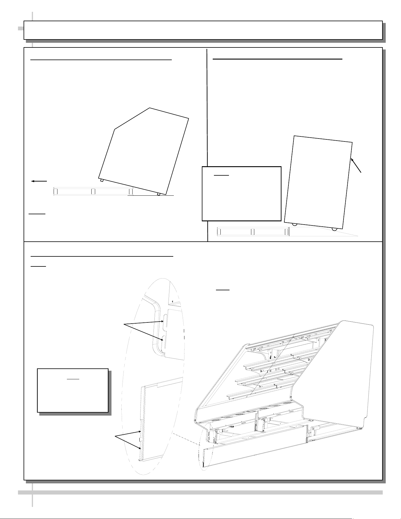
INSTALLATION: REMOVAL FROM SKID, REMOVING VERTICAL LOWER FRONT PANELS
1. Remove From Skid (Rails or Levelers)
• Remove shipping brace that may be securing
case to skid.
• Support case to prevent tipping.
• Caution! Frame Support Rails (or levelers) can
be damaged if case hits floor with heavy force!
Note: Case can be repositioned with pallet truck
when front lower panel is removed. Blocking
may be necessary to obtain adequate height.
Slide Skid Out
• Carefully slide unit to
rear of skid and tip
backward off skid.
• Illustration may not
reflect every feature
or option of your
particular case.
2. Remove Case From Skid (Casters)
Remove shipping brackets that may be securing
casters to skid
• Place ramp up against skid (to allow case to
smoothly slide off from skid).
• Maintain support of case at all times or center
of gravity may cause case to fall.
• Unlock Casters. Roll unit to rear of skid. Roll
down ramp and off from skid.
Ramp
Support
while
rolling
case
down
ramp.
Note: Illustrations
shown reflect a general
outline of sample
cases and do not reflect
features or options of
your particular model.
3. Removing Vertical Lower Front Panels
Note: No screw removal required: Simply lift lower front panel up (off hooks) and out (away from case).
View of Front Panel
(Removed & Reversed)
Hooks For Lower
Front Panel
Slots For Lower
Front Panel
Note
Lower Front Panel
Removed & Reversed
For Illustrative
Purposes Only
Note: Illustration below reflects case unit with front flat
glass. Your case may not reflect every
feature or option of this particular case.
However lower front panel removal illustration will apply.
6
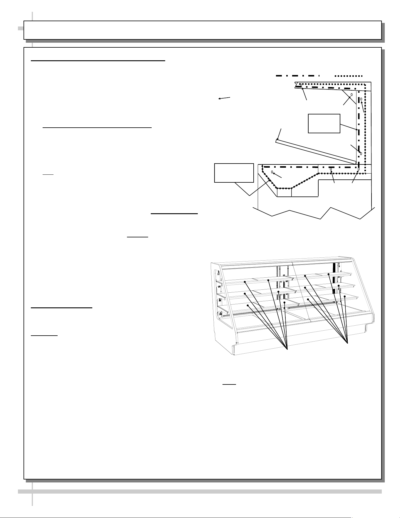
INSTALLATION, CONT’D: ADJUSTING FRONT PANELS / ADJOINING UNITS / GLASS SHELVING
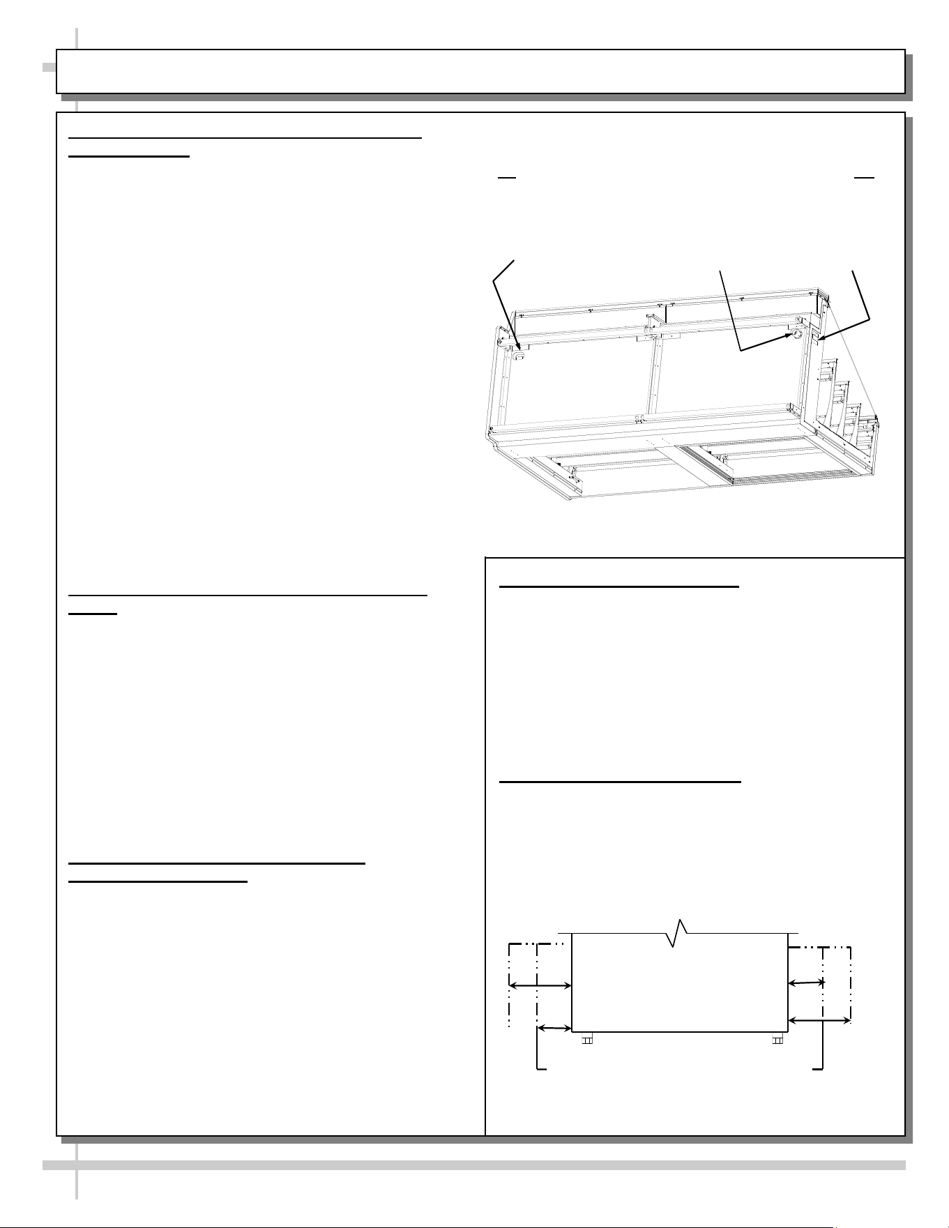
4. Bolting and Caulking Units Together
Follow these steps to assure a secure, level lineup.
A. Begin all lineups leveling from highest point of
floor.
B. After the ’first’ case is level, apply industrial grade
butyl caulk on non-visible areas (at case end).
Use industrial grade silicone sealant on visible
areas (at case end).
C. Form Two (2) Caulk/Sealant Lines: (Sanitation
and Refrigeration). See illustration at mid-right for
outline of caulk/sealant lines.
D. Line up ‘second’ case bolt-hole to bolt-hole to
‘first’ case.
E. Using SCC-supplied bolts (found in hole locations
OR in installation packet), insert bolts in bolt hole
locations (shown at top-right). You may need to
remove decking to access lower bolt holes.
F. Caution! Front of cases MUST be flush with each
other! After leveling, all cases to be same height.
G. Using SCC-supplied nuts & bolts, lightly tighten
each of the 5 to 8 bolts in a cross-wise pattern.
Work your way around the pattern, tightening
more firmly at each pass. Do not firmly tighten
one bolt and then start on the next!
H. After the cases are bolted together, level the
‘second’ case. Repeat this process for each case
to be adjoined.
I. After all lined-up cases are level, seal all seams
with industrial grade silicone sealant.
• See illustration at top-right.
5. Glass Shelving
If your unit has glass shelving, it will be packed
separately.
Caution! Carefully remove from packaging.
• Grasp firmly and carefully install.
• Caution! Check that plastic edging is intact
before placing glass shelving onto brackets!
• Plastic edging must NOT be removed from glass
shelves. Contact Structural Concepts for
replacement edging (see TECHNICAL
SERVICE CONTACT INFORMATION section).
• Check that glass shelving is in proper position
before placing product in case.
• See illustrations at mid and lower-right showing
both curved and flat front glass (optional).
Deck
Approximate hole
locations pointed
at with arrows
( ) for bolting
units together.
Sanitation Bead
Refrigeration Bead
Sanitation
Bead
Refrigeration
Bead
Glass
Shelves
Glass
Shelves
Note: Illustration above reflects dual case unit with
glass in end panels. Your case may not reflect
every feature or option of this particular case.
7
INSTALLATION, CONT’D: ELEC. CONNECTIONS / BALLAST BOX / LED DRIVER (REMOTE UNITS)
• Knockouts are on the underside of ballast box /
LED driver box making electrical connections.
• Voltage rating is on serial label at case rear.
• Remote case Illustration shown below reflects flat
front glass. Your case may differ (but electrical
layout will be accurate).
• Note: Wiring process must be performed by
certified electrician only.
6. Electrical Connections (Remote Units)
Ballast / LED Driver
Remove front panel. See INSTALLATION:
REMOVAL FROM SKID, REMOVING VERTICAL
LOWER FRONT PANELS section in this manual for
instructions.
• Stub-up connections are in ballast box.
• Remove ballast box / LED driver box cover.
Terminal
Strip
Ballast / LED
Driver
Wire
Route
PBV
Ballast Box /
LED Driver Box
Note: Illustration reflects remote Model GHBSS5R.4986A
with front panel removed for illustrative purposes only.
See next page for self-contained model GHDSS850R.
8
INSTALLATION, CONT’D: ELEC. CONNECTIONS / BALLAST BOX / LED DRIVER (SELF-CONTAINED)
• Remove electrical raceway cover.
• Knockouts are on the underside of electrical race
way for making electrical connections.
• Voltage rating is on serial label at case rear.
• Self-contained case Illustration shown below
reflects curved front glass. Your case may slightly
differ (but electrical layout is accurately portrayed).
• Wiring process must be performed by certified
electrician only.
Ballast / LED
Driver
Wire Route
PBV
7. Electrical Connections (Self-Contained Units)
Front Ballast / LED Drivers:
• Remove front panel.
• See INSTALLATION: REMOVAL FROM SKID,
REMOVING VERTICAL LOWER FRONT
PANELS section in manual for instructions.
• Stub-up connections are in ballast box.
Ballast / LED
Driver
(Optional)
Note: Illustration reflects self-contained Model
GHBSS5R.4986A with lower-front panel and electrical
raceway cover removed for illustrative purposes only.
See previous page for remote model GHDSS850R.
Main Power
Switch
Temperature
Controller
Terminal
Strip
Contactor
9
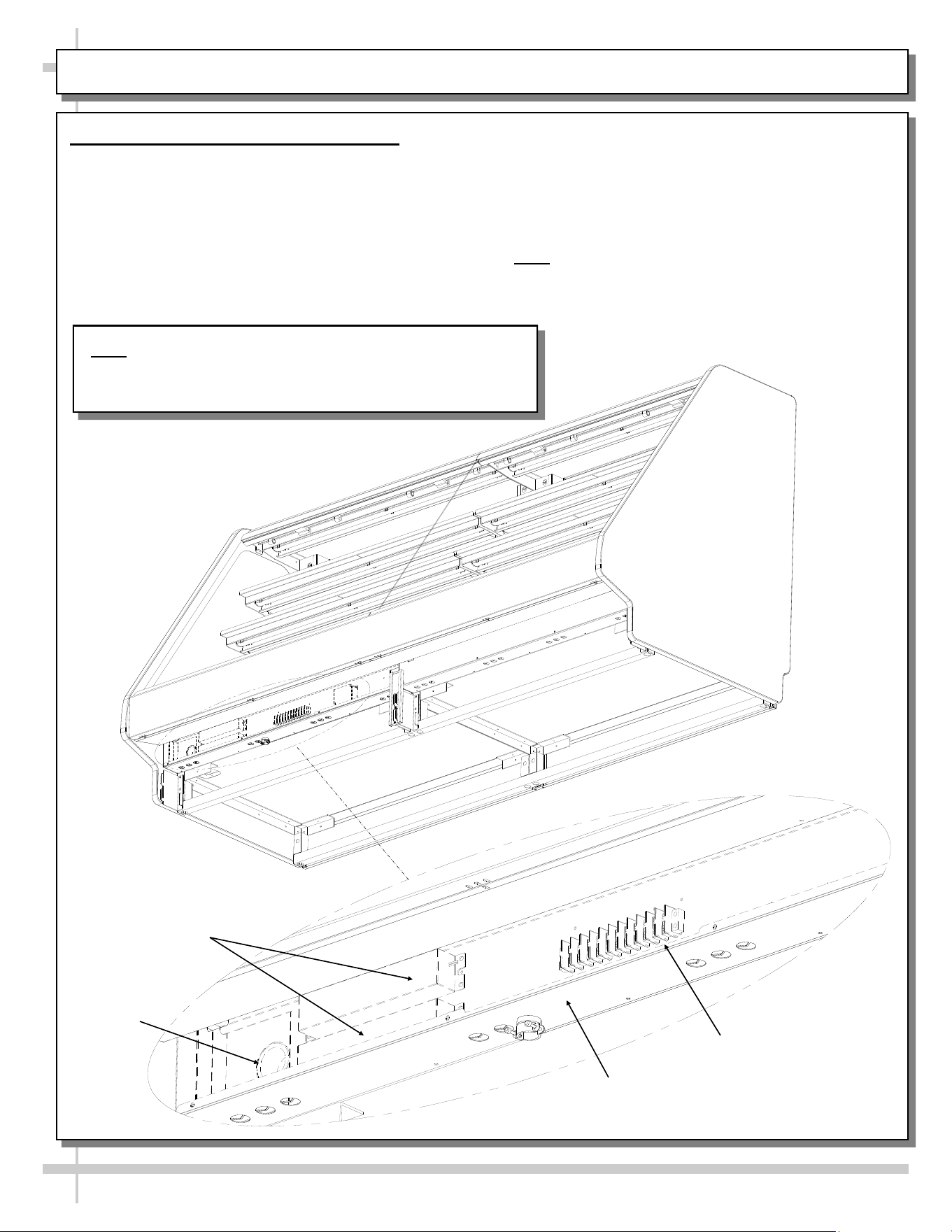
INSTALLATION, CONT’D: UNDERSIDE FIELD ACCESS COMPONENTS (MODEL GHSSEH456RLB)
8. Underside Field Access Box Components and
Underside Refrigeration Line Route
• On certain models, field access components (a
variety of which is shown below) are at underside.
• Model GHSSEH456RLB is illustrated below; your
underside component layout may vary.
• Caution! Only certified electricians are to perform
electrical connectivity duties.
• To access large field access box, two screws (at
case front) must be removed and box slid out.
Note: Illustration Reflects Remote
Model GHSSEH456RLB With
Underside Electrical Components.
Your Case May Vary.
4” x 4” Field
Access Box
Dixell®
Display
LED
Drivers
Temperature
Controller
Transformer
Refrig.
Lines
LED
Drivers
Terminal Blocks
Fuse Block
Remove Screws (Typ.)
to Slide Out Large Field
Access Box From
Underside Of Case
10
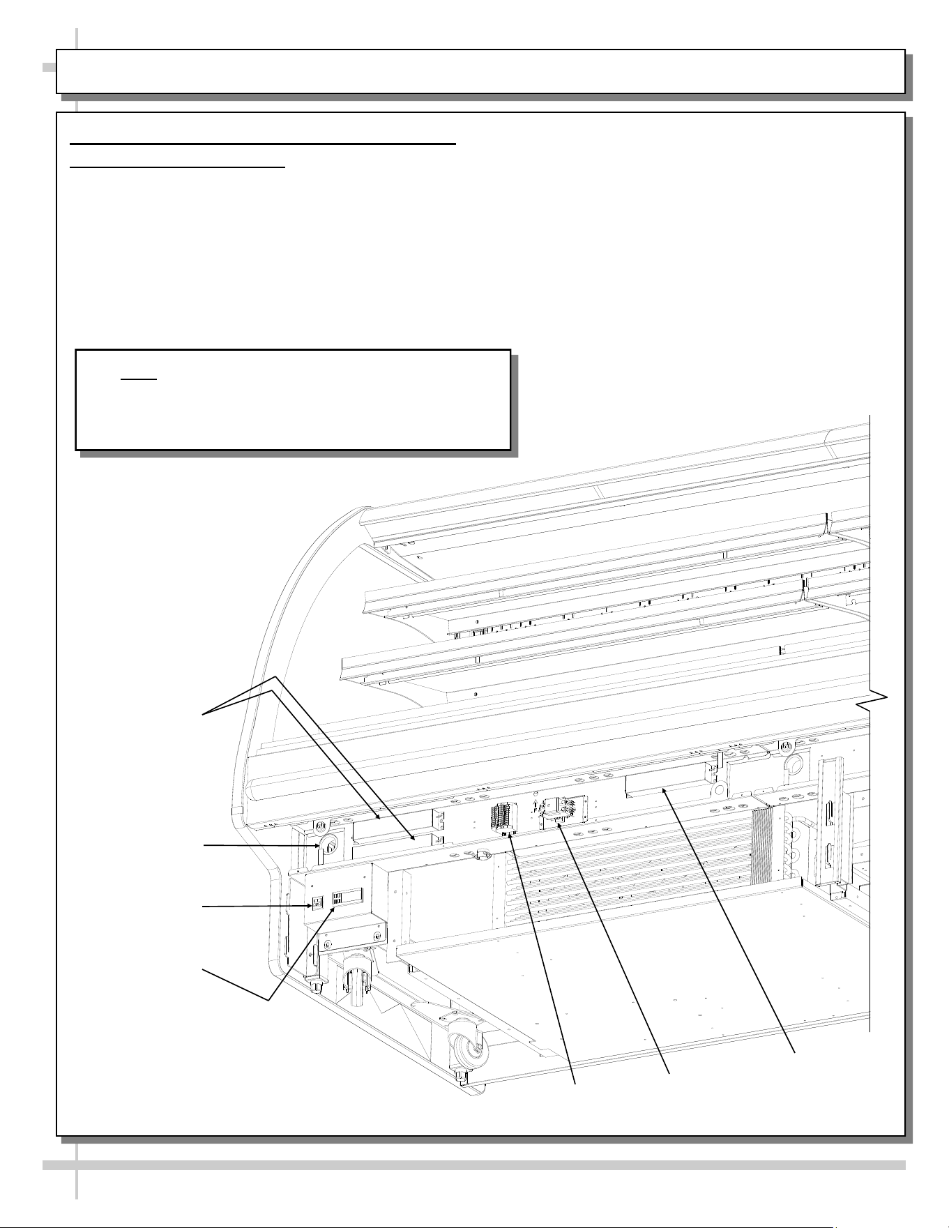
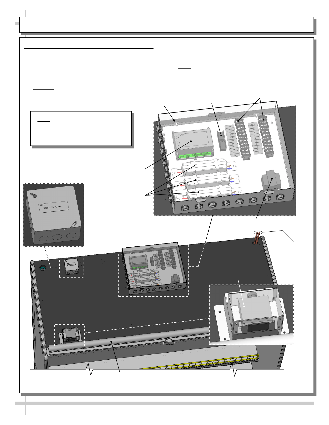
INSTALLATION, CONT’D: TOPSIDE FIELD ACCESS COMPONENTS (MODEL GHSS675RLB.5422A)
9. Topside Field Access Box Components and
Topside Refrigeration Line Route
• On certain models, field access components
(a variety of which is shown below) are topside.
• Model GHSS675RLB.5422A is illustrated below;
your topside component layout may vary.
• Caution! Only certified electricians are to
perform electrical connectivity duties.
Model GHSS675RLB.5422A
Shown Above
• To access large field access box, two screws
(at case rear) must be removed and cover lifted
up and off.
• *Note: See MAINTENANCE: OPTIONAL NIGHT
AIR CURTAIN ATTACHMENT... section in this
manual for night curtain operating instructions.
Dixell®
Display
4” x 4”
Field Access Box
Large Field
Access Box
LED Drivers
Temperature
Controller
Terminal Blocks
Fuse Block
Transformer
Screw (Typ.)
Note: Illustration Reflects Remote
Model GHSS675RLB.5422A With
Topside Electrical Components.
Your Case May Vary.
*Optional Night
Air Curtain
Refrigeration
Lines
(Top Exit)
11
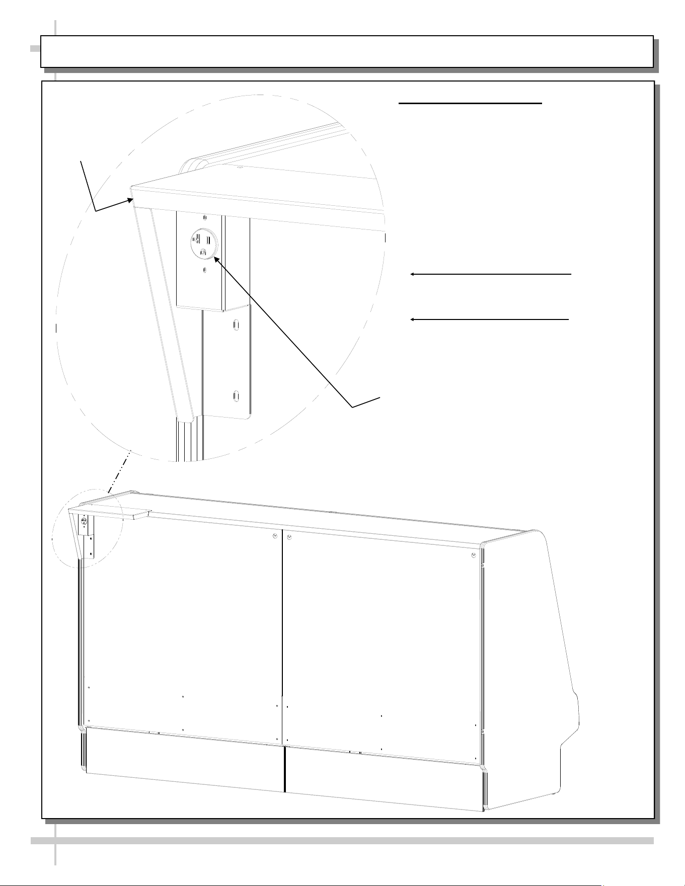
INSTALLATION, CONT’D: ELECTRICAL CONNECTIONS / OPTIONAL SCALE STAND
Scale
Stand
Scale Stand
Receptacle
Model GHSSACS857R Shown Below
With Scale Stand and Receptacle.
Your Model May Vary.
View of Typical Case With
Scale Stand and Receptacle
10. Optional Scale Stand
• Scale stand is on model GHSSACS857R
(and may be on additional models).
• Scale stand is provided with isolated
ground receptacle.
• Depending upon options chosen, scale
stand may be at either left or right of
case.
12
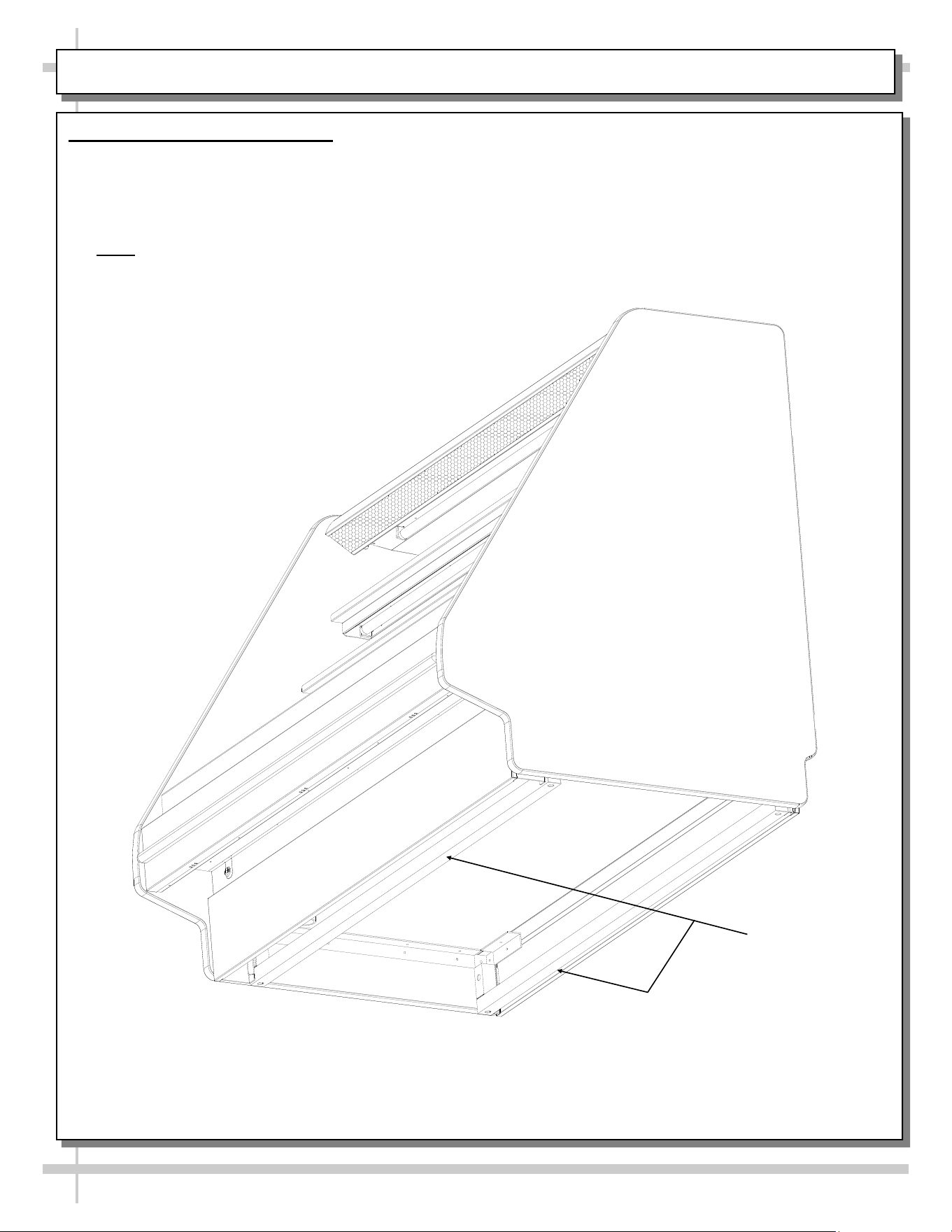
INSTALLATION, CONT’D: BASE FRAMES / SEALING TO FLOOR
11. Cases With Base Rails: Shim
• Illustration below shows case with frame support rails. End panel has been removed for illustrative
purposes only.
• Shims will be provided with all cases that have frame support rails.
• Use shims to level case.
• See illustration below.
• Note: After case is in position, it must be sealed to floor to prevent entry or leakage of liquid or
moisture.
Base Frames
13
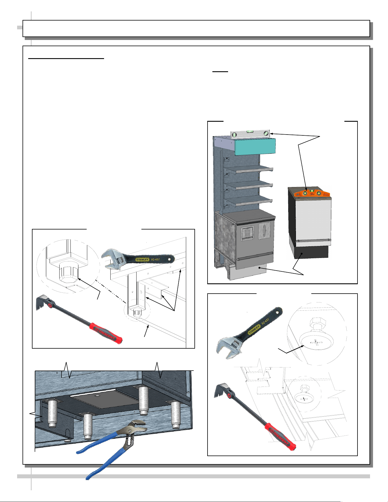
INSTALLATION, CONT’D: ADJUSTING LEVELERS
Adjustable
Wrench
Leveler
Leveler Style B
Random
Levels
Base
Frame
--- Leveler Style C ---
Toe-Kick
• Structural Concepts’ three (3) main leveler styles
(A, B and C) are shown below.
• Note: After case is level and plumb, use
silicone sealant to seal rear splash guard to
floor to prevent entry (or leakage) of liquid or
moisture. If there is no rear splash guard,
check with store manager as to whether rear
toe-kick should be sealed to floor.
Front Toe-Kicks
Indexing
Flat Pry Bar
Leveler
Adjustable
Channel Lock Pliers
Indexing
Flat Pry Bar
12. Adjusting Levelers
>> Structural Concepts utilizes three (3) different
leveler styles; they are illustrated on this page.
• After case is in position, you must adjust case so
it is level and plumb. See illustrations of random
levels on sample cases at top-right of page.
• You must remove front and/or rear toe-kicks to
access levelers. See illustrations at top-right.
• Leveler Style “A” and “B” may require the use of
an adjustable wrench and an indexing flat pry bar
(or similar pry bar) to adjust levelers.
• Leveler Style “C” may NOT have accessible base
frames to use a pry bar; if so, use adjustable
channel lock pliers to adjust levelers.
• If base frame is accessible, use indexing flat pry
bar to raise case (and adjust levelers as needed).
• DO NOT use indexing flat pry bar on toe-kicks
as they may buckle.
• DO NOT use indexing flat pry bar on end
panels as surfaces may chip or mar.
• Use indexing flat pry bar ONLY on base
frames to avoid damaging case!
Leveler Style A
Adjustable Wrench
Sample Cases With Random Levels
14
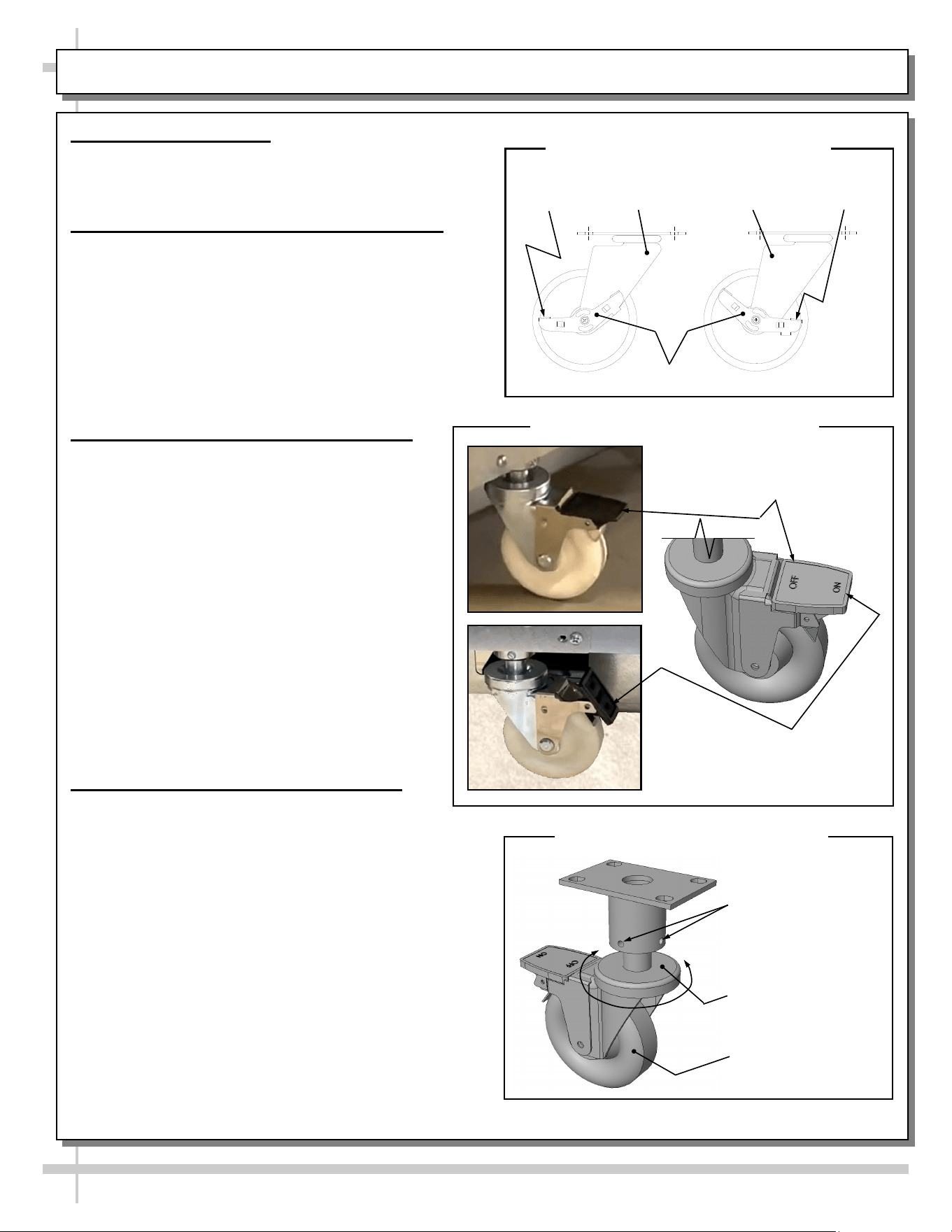
INSTALLATION, CONT’D: CASTER STYLES / LOCKING & UNLOCKING / RAISING & LOWERING
Caster Styles - Overview
>> Structural Concepts utilizes two (2) different caster
styles on its merchandisers.
>> Both caster styles are illustrated on this page.
13. Caster Style “A” - Locking/Unlocking Only
• Caster Style “A” is shown at top right on this page.
• Case must be level and plumb before locking;
levelers are usually adjusted to do so; see previous
page for leveler adjustment instructions..
• Caster assembly Style “A” is identified as having a
“front” and “rear” for these instructions.
• To lock caster, press down caster lever at “rear.”
• To unlock caster, press down caster lever at “front.”
• This style of caster cannot be raised or lowered.
14A. Caster Style “B” - Locking/Unlocking
• Style “B” casters are unlocked at shipment
(as casters are held in place by wooden
blocks and metal brackets).
• Style “B” casters are in unlocked position;
caster levers will be parallel to floor.
• After case has been moved into position,
casters may be locked. To do so, press
downward against the “ON” marking on the
caster lever.
• To unlock casters (and move case to a
different location), press downward against
the “OFF” marking on the caster lever.
Casters will now be unlocked, allowing the
case to be moved.
• See caster/lever illustrations at lower right for
specifics.
14B. Caster Style “B” - Raising/Lowering
• Style “B” vertical height adjustment ring
illustrations are shown at mid and lower right on
this page.
• Style “B” caster are utilized in lieu of levelers.
• Cases are shipped from factory with Style “B”
casters RAISED to maximum height; this position
aids in skid removal.
• After case has been moved into position, Caster
Style “B” allows vertical adjustment of case so it
may be adjusted until case is level and plumb.
• Slotted head screws MAY be tightened/loosened to
lock vertical height adjustment ring; usually, these
Slotted head screws are NOT tightened at factory.
• After case is level and plumb (as described on
previous page), must may be locked.
Caster
Vertical Height
Adjustment Ring
Caster Style B - Raising/Lowering
Locked
Caster Style A - Locking/Unlocking
Front of Caster
Assembly
Unlocked
Rear of Caster
Assembly
Caster Lever
Caster May Be Locked By
Pressing Downward
Against The ON Lever).
Caster Style B - Locking/Unlocking
Caster Lever Is Shown
In Unlocked Position.
Slotted Head Set
Screws May Be
Tightened When
Desired Vertical
Height Is Achieved)
15
INSTALLATION, CONT’D: REFRIG. LINES / STUB-UPS / DRAINS / WIRING DIAGRAMS / VENTILATION
15. Refrigeration Line Stub-Up Connections
(Remote Units)
• Remove front panel.
• Refrigerant stub-up access opening is at the
front on the left hand side of the base (see
illustration at top-right).
• Stub-up connections are accessed from inside
the case.
• Remove interior decks.
• Remove fan shroud assembly.
• Line connections are in the tub front, on the left
hand side
• Remove foam material from the entry hole
provided in the tub drain trough.
• Route refrigerant lines through access hole.
• Run case-to-case connections through
cutouts in base.
• Sweat the high and low pressure
connections.
• Fill access hole with suitable filler to insure
watertight integrity of tub.
• Illustration at top-right may not reflect every
feature or option of your particular case.
16. Refrigeration Drain Connection (Remote
Units)
• Depending upon drain access needs, either front
or rear panel may be removed to gain access to
drain stub-up.
• 1.5” male PVC stub-up connection is under the
case on the right hand side.
• Drain stub-up may be at case center in extended
length cases.
• Connect tub drain to floor drain. Maintain
1/4”-fall per foot to provide proper drainage.
• Illustration at top-right may not reflect every
feature or option of your particular case.
17. Condensate Pan / Drain Position
(Self-Contained Units)
• Remove the front panel by lifting up & out.
• Slide the condenser unit out from case.
• Condenser unit access is now available.
• Insure that the condensate pan is installed under
the PVC condensate drain trap.
• Insure that the condensate pan is plugged into
the receptacle inside base.
• Lower rear panel back into place.
• See Drain, Hose and Bracket Placement
section in Operating Manual for details.
19. Ventilation and Clearance
• Self-Contained refrigerated cases must
maintain airflow clearance of 6” (minimum) to
12” (recommended) at front and rear.
• Restriction of air can void warranty.
• Illustration below may not reflect every feature
or option of your particular case.
Check air grilles for obstructions.
Maintain airflow clearance of 6” (min.)
to 12” (recommended) at front & rear.
18. Electrical Wiring Diagram
• Each case has its own wiring diagram
folded and in its own packet.
• Wiring diagram placement may vary; it may
be placed near condenser fan cover,
ballast box, raceway cover, or other related
location.
Refrigeration
Line Stub-Ups
Access
Cutout
Drain Stub-Up (may be
at case center in
extended length cases)
Note: Illustration Below May Not Reflect Every
Feature or Option of Your Particular Case
16
INSTALLATION, CONT’D: DISPLAY CASE START-UP (CASE / LIGHTS / TEMP. CONTROLLER / SST)
Cap
Plug
Receptacle
Raceway Receptacle, Plug and Cap
Raceway
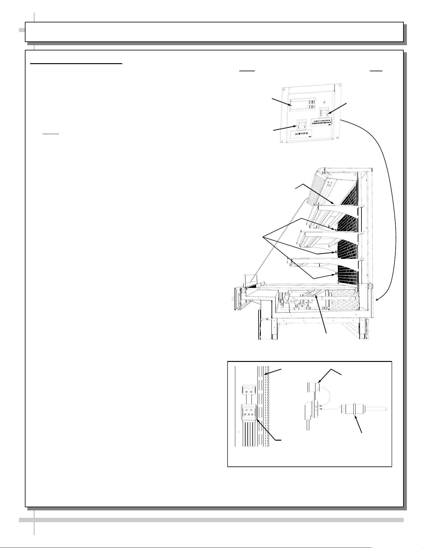
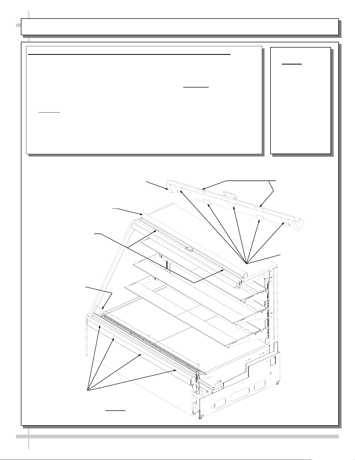
20. Display Case Start-Up
A. Case
• Remote: Case will power-up when properly field
wired (or plugged in).
• Self-contained: Turn main power on.
• After case is powered up, lift curved or flat front
glass by grasping lift handle and raising (see
illustration at right).
• Note: Illustration at right reflects flat front glass.
Yours may have curved front glass.
• Lift deck to check that coil fans are running.
• Coil fans (and in self-contained units, compressor
motor) should turn on.
B. Lights
• Turn lights on.
> Switch is either at case front, attached to rear
plenum, above top shelf (as shown at right) or at case
rear (as shown at top-right).
> In cases with NO SWITCH, lights will come on
when case powers up.
• All lights should come on at the same time. If
bulbs are fluorescent, first time lighting may
require a short warm-up period. LEDs have no
warm-up period.
• Slightly dim / flickering of new bulbs is normal.
If lights do not turn on, check raceway plugs.
• Lighting is wired in series so all lights must be
plugged in or receptacles capped for case
lights to be on. See illustration at right.
• LED Lights: If lights do not come on, check that
plug is properly inserted into socket.
C. Temperature Controller (All Self-Contained
Units and some Remote Units)
• Check that compressor symbol light is on.
• After case has run for a few minutes, check that
temperature starts to drop.
• If temperature controller does not begin cooling
(in a few minutes) see temperature controller
section in this operating manual for instructions.
• Remote units (without temperature controller on
case): Verify that refrigeration requirements listed
on serial label (found on the case) are being met.
D. Saturated Suction Temperature (Remote)
• See serial label on case for suction temperature
requirements and BTU requirements.
• See serial label on case for defrost schedule and
temperature termination parameters.
Main Power
Switch
Light Switch (On
Certain Self-
Contained Units)
Temperature
Controller
Coil Fans
Raceway
Plugs (See
Illustration
Below)
Light Switch at Rear
Plenum Above Top Shelf
(On Remote Units and
Various Self-Contained
Units)
Self-Contained Unit Control Panel
(With Temperature Controller)
17
Note: See INSTALLATION section in manual for:
• Front Panel adjustment and removal
• Angled Base adjustment and removal
• Vertical Base adjustment and removal
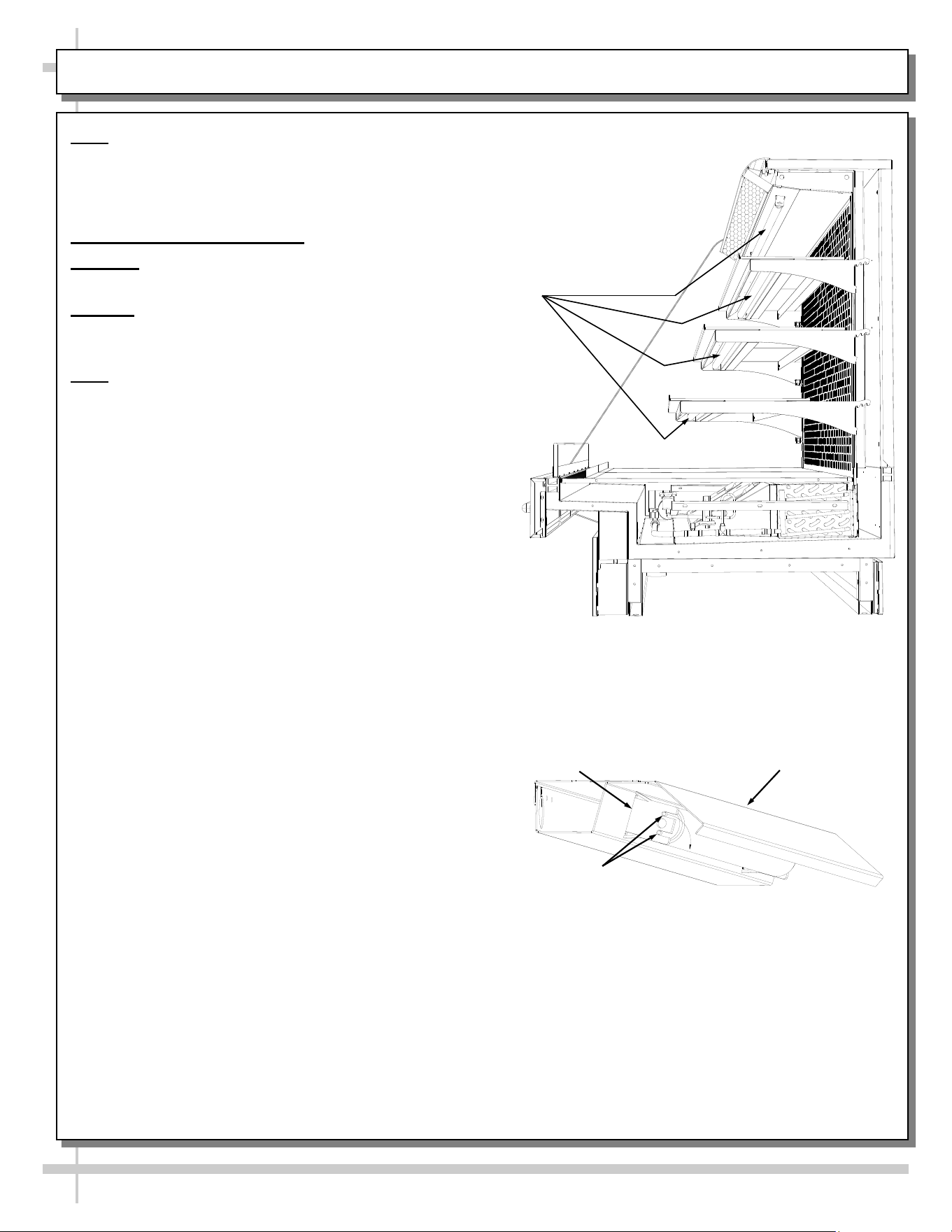
1. Fluorescent Light Fixtures
Warning! Disconnect power before providing
maintenance and service to unit.
Caution: Lamps have been treated to resist
breakage and must be replaced with similarly
treated lamps.
Note: Warranty will be void if claims arise from
negligence, misuse of goods, extreme
environmental conditions or improper
maintenance. See Overview And Warnings
section in this operating manual.
• Light fixtures are located on underside of shelf
assemblies and at the top inside of case.
• See illustration at top-right for locations.
Removal of lamp:
• Rotate lamp (1/4-turn) either direction to disengage
(upper or lower) pins/contacts from lamp-mounting
sockets.
• Remove bulb by applying even pressure from back
side at the bulb ends and pulling the remaining
contact from sockets.
• See illustrations at mid and lower-right.
Installation of lamp:
• Align pins with slot.
• Insert pins into socket by rotating the bulb 1/4-turn
to secure either the (upper or lower) pin contacts
into the sockets.
• Rotate remaining bulb contacts (1/4-turn) into
remaining lamp mounting socket contacts.
• See illustrations at right.
See next page for LED Light Fixture information
MAINTENANCE: FLUORESCENT LIGHT FIXTURES / REMOVAL & REPLACEMENT
Lamp Pins
Light Socket
Light Fixture
Fluorescent
Light
Fixtures
Above illustration has end panel removed
for illustrative purposes only.
18
MAINTENANCE, CONT’D: LED STYLE LIGHT FIXTURES / LED CLIPS / CONNECTIONS / THERMOMETERS
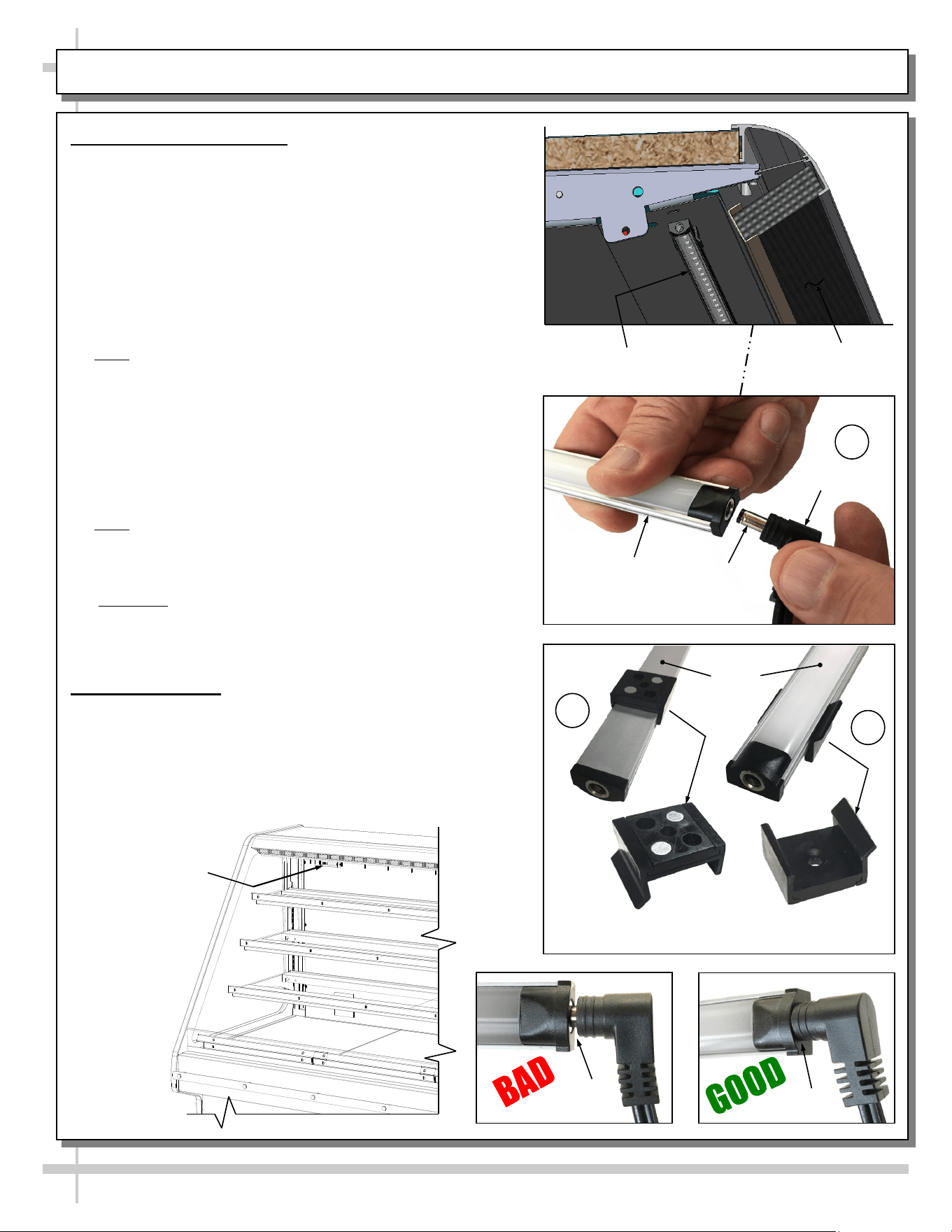
2. LED Style Light Fixtures
Removal of Faulty LED Lights:
• Contact Structural Concepts’ Technical Service
Department for replacement LED lights.
• Turn off LED light switch.
• To remove faulty LED light, follow these steps:
A. Disconnect plug from LED light.
B. Using both hands, grasp LED light assembly (with its
magnetic mounting clips). Pull downward and off its
shelf (or header).
C. Remove magnetic mounting clips from LED light by
pressing against flange part of clip with thumb.
>> Note: Mounting clips MAY be riveted to shelf or header.
In such instances, simply remove LED light from mounting
clips by pressing against flange part of clips with thumb.
Replacement of LED lights:
• Attach magnetic mounting clips onto LED light.
• Adjust magnetic mounting clips so they are equally
spaced on LED light.
• Reattach LED light assembly to its shelf/header.
• Position properly in shelf/header.
>> Note: If mounting clips are riveted to shelf (or header),
attach by placing LED in base of clip and then snapping into
clip at FLANGE SIDE.
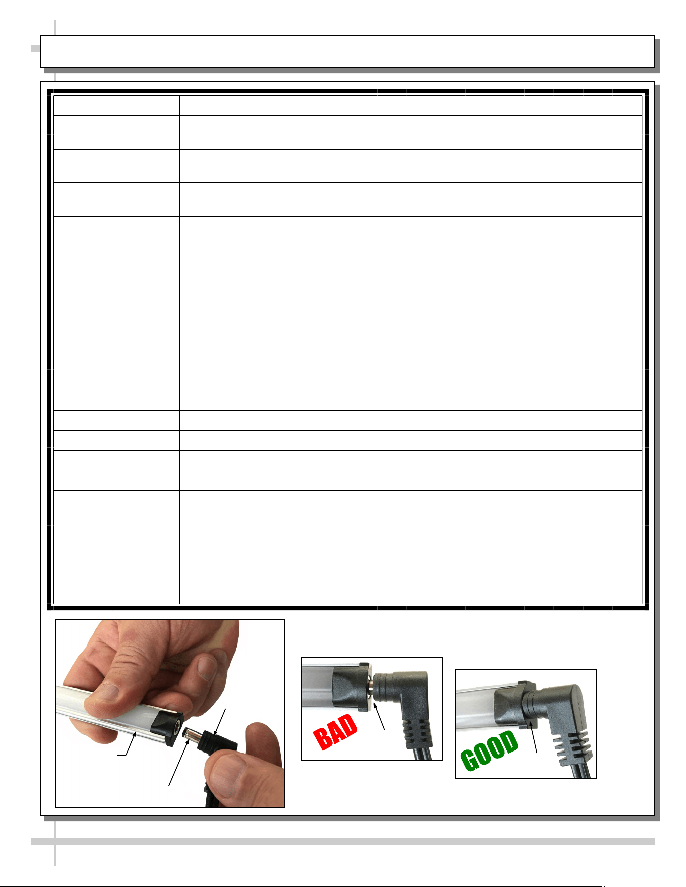
• Press plug’s barrel-shaped insert deep into LED light.
• Important: If plug is not inserted ALL THE WAY IN the
LED light’s orifice, the light may not energize. See “BAD”
vs. “GOOD” insertion illustrations at right.
• Turn LED light switch back on.
3. Thermometers
• Thermometers are is located at rear plenum.
• Thermometers reflect internal air temperature only (not
actual food temperature).
• Use probe thermometers to determine product temp.
• See illustration below for common location of
thermometer (your location may slightly vary).
Honeycomb
LED Light
Magnetic Mounting
Clip View #2
LED
Lights
B
A
Plug
Barrel
Shaped
Insert
LED
Light
C
Magnetic Mounting
Clip View #1
No Gap
Gap
Common Location
of Thermometer
(May Vary From
Case to Case)
19
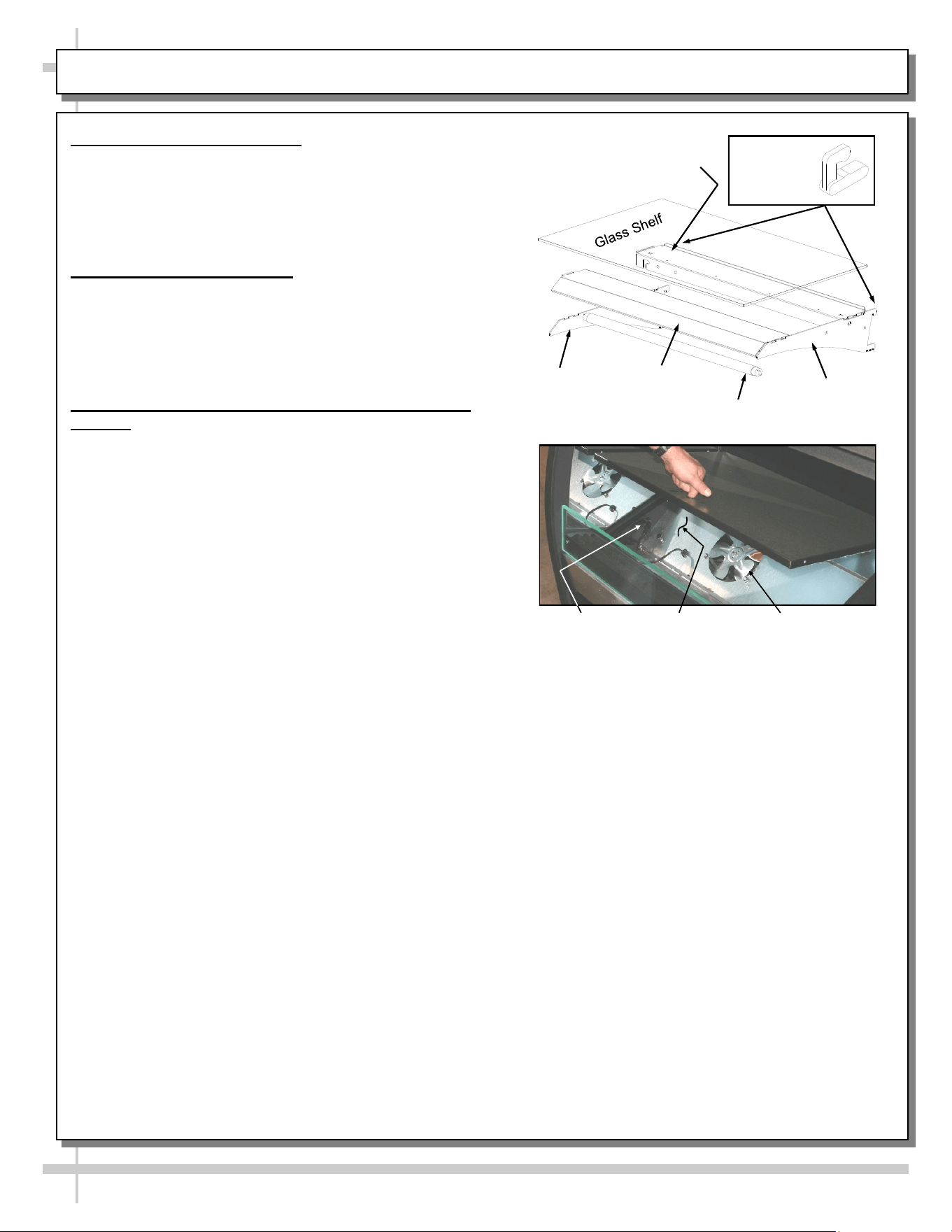
MAINTENANCE, CONT’D: BRACKET RETAINER REMOVAL / SHELF ASS’Y REMOVAL / DRAIN / TXV
4. Bracket Retainer Removal
• To remove brackets, it may be necessary to
remove the nylon shipping bracket retainers.
• Pliers will be required to accomplish this task.
• See illustration at top-right for location of bracket
retainers.
5. Shelf Assembly Removal
• Remove glass shelves
• For lighted shelving, unplug the light cord.
• Remove rear shelf support.
• Remove shelf light cover from brackets.
• Lift brackets up and out.
6. Drain and Thermostatic Expansion Valve (TXV)
Access
• The drain and thermostatic expansion valve are both
accessible from the front of the case.
• Unplug the fans (one plug per side) and remove the
fastener from the access panel in the front right (or
left) corner of the unit.
• The drain and the thermostatic expansion valve
(TXV) are directly below the access panel.
Fan Plug
TXV Panel
Shelf
Bracket
Shelf Light
Cover
Rear Shelf Support
Lamp
Bracket
Bracket
Retainer
Locations
Evaporator
Fan
20
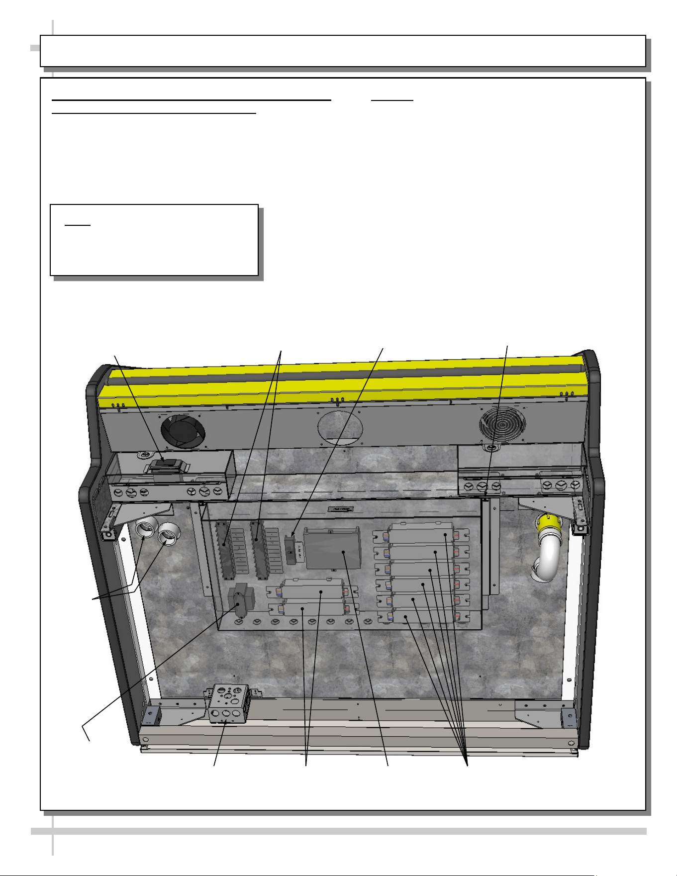
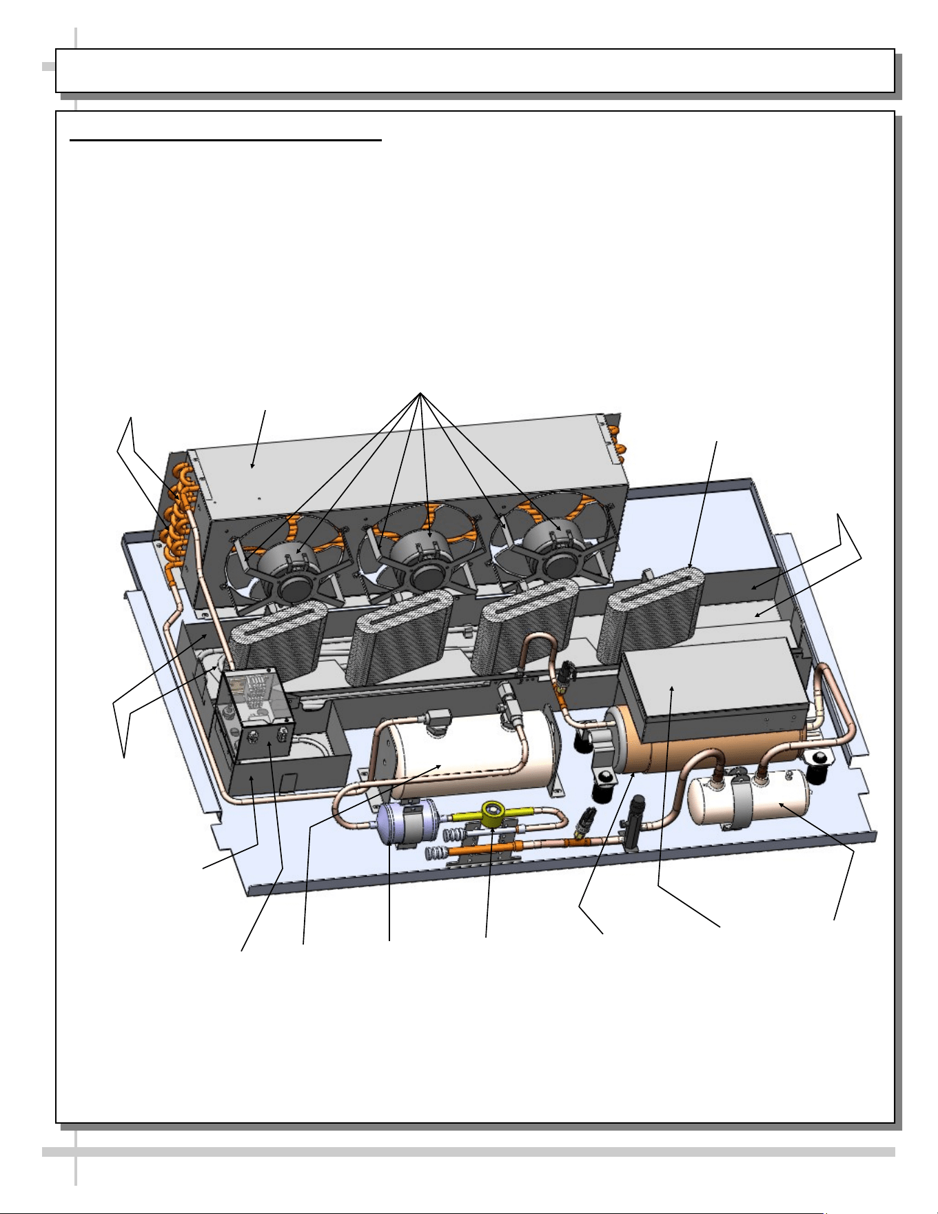
MAINTENANCE, CONT’: REFRIG. PACKAGE ILLUSTRATION (FROM S.C. MODEL GHDSS850R)
7. Refrigeration Package Configuration
• Illustration shown is from self-contained model GHDSS850R.
• Your particular refrigeration package may have a slightly different refrigeration package layout.
Accumulator
Scroll
Compressor
Electrical Box
(Starter Unit &
Relay)
Filter Dryer
Sight Glass
Overflow Pan
(For Hot Gas
Condensate Pan)
Condenser Coil
Housing
Condenser Coil
Fans & Housing
Hot Gas
Condensate
Coils and Pan
Overflow Pan
Electrical Box)
Receiver
Condenser
Coils
Hot Gas
Condensate
Coil Pan
Condenser Coil
Wicking Material
(Typical)
21
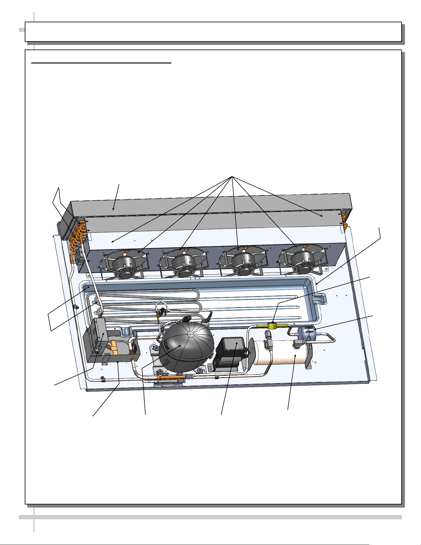
MAINTENANCE, CONT’: REFRIG. PACKAGE ILLUSTRATION (FROM MODEL GHSS660R)
8. Refrigeration Package Configuration
• Illustration shown is from self-contained model GHDSS660R.
• Your particular refrigeration package may have a slightly different layout.
Compressor
Electrical Box
(Starter Unit &
Relay)
Filter
Dryer
Sight
Glass
Overflow Pan
(For Hot Gas
Condensate Pan)
Condenser Coil
Housing
Condenser Coil
Fans & Housing
Hot Gas
Condensate
Coils and
Pan
Overflow Pan
Electrical Box)
Receiver
Condenser
Coils
Hot Gas
Condensate
Coil Pan
22
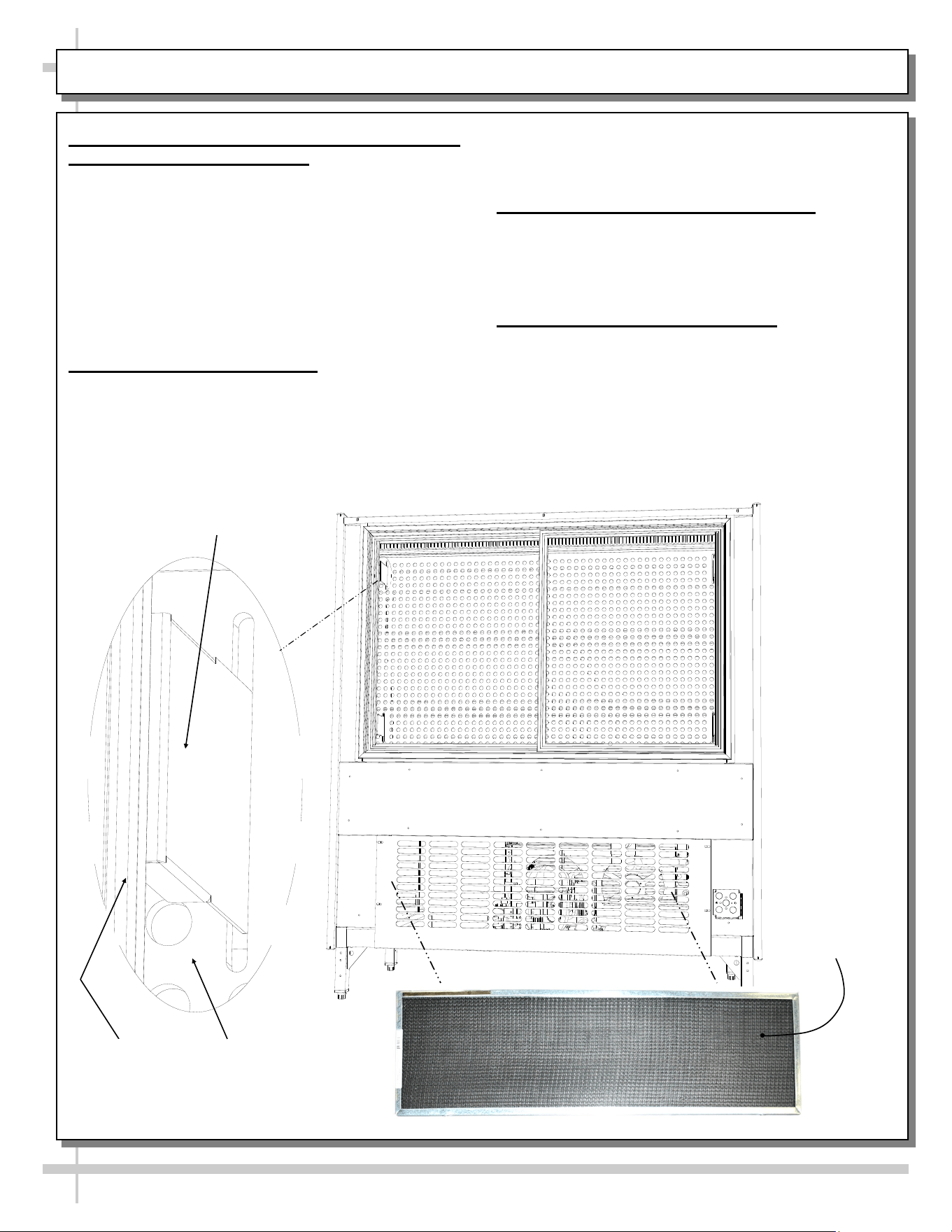
MAINTENANCE, CONT’: OPTIONAL SLIDING REAR DOORS / PERF. PLENUM / COND. COIL FILTER
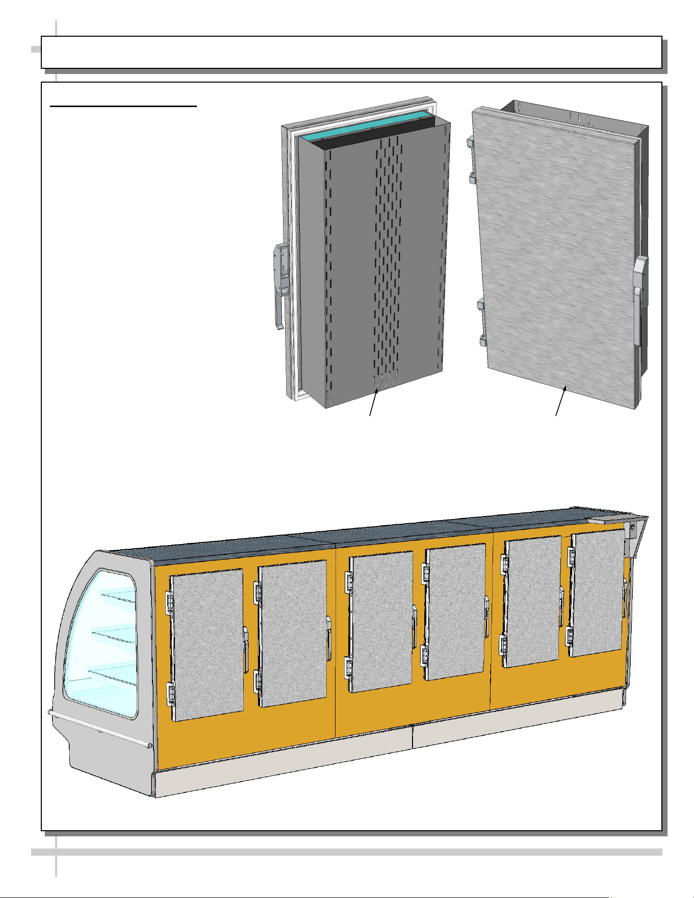
9. Rear Sliding Doors/Perforated Acrylic Plenum
(Optional) is Illustrated Below
• Rear sliding doors have metal brackets
connected to perforated acrylic plenums.
• These perforated acrylic plenums are designed to
maintain proper refrigerated temperature.
• When sliding rear doors open, the perforated
acrylic plenums also slide open (allowing access
to contents inside case).
• Be sure to completely close the rear sliding doors
after accessing case contents.
10. Rear Sliding Door Removal
• Rear sliding doors can be removed WITHOUT
removing the perforated acrylic plenum.
• Simply slide rear sliding doors to case center, lift
upward and out. Replace in reverse order the
doors were removed.
11. Perforated Acrylic Plenum Removal
• Access perforated acrylic plenums from front of
case.
• Simply lift the pieces up and out of case.
• Replace in reverse order they were removed.
12. Magnetic Condenser Coil Filter
• This filter helps prevent dust particles from
entering condenser coil.
• See GENERAL CLEANING (TO BE
PERFORMED BY STORE PERSONNEL)
section in operating manual for cleaning
specifics.
Edge of
Outside
Door
Metal Bracket (Connecting
Perforated Acrylic Plenum
To Rear Sliding Doors)
Perforated
Acrylic
Plenum
Magnetic
Condenser Coil
Filter
23
MAINTENANCE, CONT’D: OPTIONAL NIGHT AIR CURTAIN ATTACHMENT & OPER. INSTRUCTIONS
NOTE: THE
BELOW
ILLUSTRATION
MAY NOT
EXACTLY
REFLECT
EVERY
PARTICULAR
CASE’S
FEATURES OR
OPTIONS.
13. Optional Night Air Curtain Attachment & Operating Instructions
1. Use caution when handling night air curtain.
2. Display case may come with night air curtain already attached. If not, a retrofit kit will
be provided. If using SCC-supplied retrofit kit, place night air curtain on top of case as
shown.
3. Grasp the handle and pull downward to desired location OUTSIDE of the acrylic air
deflector (see illustration below).
4. To return night air curtain to its retracted position, grasp handle, lift up and away from
its magnetic attachment and carefully wind night air curtain back into roll.
5. Caution! Do not allow spring-loaded night air curtain to freely snap back into roll.
Doing so can eventually destroy night air curtain’s tension and retractability.
6. To entirely detach night air curtain from case, carefully return curtain into its housing.
Lift night air curtain straight up and off. Note, due to magnet strength, two people may
need to grasp each end of night air curtain and lift upward together.
7. Store in safe place, where night air curtain will not be damaged.
Night Air Curtain
Retraction Magnets
Night Air Curtain
Retraction Magnets Attachment
Points (Along Plate Outside
Acrylic Air Deflector)
Enlarge View of Night Air Curtain
(Underside / Detached)
Acrylic Air
Deflector
View of Night Air Curtain
(Topside / Attached)
Night Air Curtain
Retraction Magnets
Night Air Curtain
Retaining Magnets
(To Hold Curtain
Housing to Top
Board of Case)
24
MAINTENANCE, CONT’D: REAR SWINGING/HINGED DOORS (MODEL GHSS1252RLB.6796 ONLY)
Model GHSS125RLB.6796F (With Rear
Swinging Doors) Is Shown Above
14. Rear Swinging Doors
• Model GHSS1252RLB.6796 has
rear swinging doors with metal
hinges and handles.
• Doors have rear plenums that
open/close with door as part of
design.
• Doors are carefully aligned.
Caution! Do not slam doors
with extreme force or hinges
and/or handles could loosen
or be damaged.
• See illustrations at right and
below.
Inside Rear Swinging
Door (With Inner
Plenum Shown)
Outside Rear Swinging
Door (With Hinges and
Handle Shown)
25
GENERAL CLEANING (TO BE PERFORMED BY STORE PERSONNEL)
AREA FREQ. INSTRUCTIONS
Exterior Daily Acrylic/Plexiglas® (Sneeze Guards/Dividers, etc.): Clean with mild soap and
water solution and a soft cloth. Do NOT use household or commercial glass
cleaners with ammonia (including Windex) on acrylic or Plexiglas® as it can cause
acrylic to degrade and become ‘cloudy’ over time.
Daily PVC Price Tag Molding: Clean thoroughly with microfiber cloth or non-abrasive
sponge and general cleaning products such as mild detergent, Windex, Plexi-Clean
or Formula 409. Do not use paper towel or “magic erasers” as they can permanent-
ly etch surface. Also, do not us harsh chemicals such as trichlorethylene, acetone
or lacquer thinner.
Daily Glass / Mirrors / Shelving: Clean side glass, glass shelves, and mirrors with a
household or commercial glass cleaner.
Daily Shelves/Decking: Non-glass shelves and decking can be cleaned with a warm
soap and water solution and soft cloth.
Daily End Panels, Front Panel, Rear Swinging Doors, Toe-Kick, etc.: Wipe off all
surfaces with warm water and mild soap solution and non-abrasive cloth.
Weekly Wood, Laminate and Painted Surfaces: Clean with mild soap and water solution
and a soft cloth.
Weekly Magnetic Condenser Coil Filter:
• This filter helps prevent dust particles from entering condenser coil.
• It is accessible at case rear.
• Clean magnetic condenser coil filter by following either of these steps:
1. As magnetic condenser coil filter is dishwasher safe, remove from case
(no screw removal required) and use a rag or soft-bristled brush to wipe off
excess dust particles from filter. Run in normal dishwasher cycle. Remove
from dishwasher. Dry with soft cloth or paper towel. Return to case.
2. If not using dishwasher, remove magnetic condenser coil filter from case.
Use a rag or soft-bristled brush to wipe off excess dust particles from filter.
Submerse in warm, soapy water. Use soft-bristled brush to remove dust,
dirt, grease and grime that may collect on filter. Rinse thoroughly.
3. Dry with soft cloth or paper towel (as shown below). Return to case.
Interior Daily Shelves/Deck: Shelves/Deck can be cleaned with a warm soap and water solu-
tion. For stubborn stains/residue, decks can be removed and cleaned with soap
and water solution or submersed in hot, soapy water solution. Rinse thoroughly.
Dry. Return to case.
Weekly Shelving Brackets / Air Return Grilles / Decking / Rear Plenum
• Wipe off shelving brackets, air return grilles, decking and rear plenums with
moist cloth.
• Shelving brackets can be removed for more thorough cleaning.
• Air return grilles can be removed for more thorough cleaning.
• Decking is NOT to be removed by store personnel.
Monthly Condenser Coil: Vacuum or brush grille condenser coil at case front. Use metal or
fiber brush to remove dust and dirt that can collect on condenser coils. Be careful
not to damage the fins on the coil. See INSTALLATION section in manual for side
panel removal information.
26
TROUBLESHOOTING (TO BE PERFORMED BY STORE PERSONNEL)
CONDITION TROUBLESHOOTING
Case Not Lining Up See INSTALLATION section in manual for instructions on properly aligning
case (alongside other cases) and adjusting levelers (or rails).
Water Is On The Floor Call service provider.
Fan Emits Excessive Noise Call service provider.
Case Lights Are Not
Working
Check that Light switch is in the on position.
Check that ALL of the light cords and plugs are properly connected. See
MAINTENANCE FUNDAMENTALS - STANDARD LIGHT FIXTURES or
MAINTENANCE FUNDAMENTALS - LED LIGHTS section in manual.
If case lights still do not come on, call service provider.
Case is Not Holding
Proper Temperature
If a large amount of warm product was added to the case, it will take time
for the temperature to adjust. Pre-chilled product before placing in case.
Check that the case is not in the sun or near a heat or air-conditioning vent.
See OVERVIEW / TECHNICAL INFORMATION / WARNINGS section in
this manual for specifics.
If case is located near front doors, temperature fluctuation can hinder unit’s
ability to maintain temperature.
Check that air filter and condenser coil has been cleaned. See GENERAL
CLEANING (TO BE PERFORMED BY STORE PERSONNEL) section in
this manual for specifics.
Check air return grilles (area at front of decking) for obstructions. DO NOT
set product on air grilles as this will prevent proper airflow!
If case still is not holding proper temperature, call service provider.
27
GENERAL CLEANING (TO BE PERFORMED BY TRAINED SERVICE PROVIDERS ONLY)
AREA TO CLEAN FREQUENCY INSTRUCTIONS
Case Interior Monthly Evaporator Fan Shroud Area (Under Decking): Caution! Due to
rotating fans in area, turn off case and disconnect plug from
wall outlet before beginning fan shroud (and surrounding tub
area) cleaning! 1) Turn off power. 2) Remove decks from case. 3)
Clean fan shroud area (and surrounding tub area) with moist cloth.
Quarterly Tub & Drain: Caution! Due to rotating fans in area, turn off
case and disconnect plug from wall outlet before beginning
tub & drain cleaning! Vacuum tub under decks. Clean with soap
and water solution. Wipe dry with clean cloth. Keep drain free of
debris to prevent clogging.
28
CONDITION TROUBLESHOOTING
Case Not Lining
Up
See INSTALLATION section in manual for instructions on properly aligning case
(alongside other cases) and adjusting levelers.
Water Is On The
Floor
Caution! Water on flooring can cause much damage! Until cause is determined (and
repaired), following these procedures:
• Use wet-dry vacuum (or mop & bucket) to remove standing water.
• Use ‘catch pans’ for water to drain into. Swap out regularly until case has drained.
Note: See Drain, Hose and Bracket Placement Illustrations sheet in this manual for
views of different condensate systems used in display cases.
Check that the drain trap is free of debris.
Check that the drain hose is correctly positioned over condensate pan (or floor drain,
for remote units).
Check store conditions. To prevent condensation in Type 1 environments, maximum
conditions are to be 55% humidity / 75 °Fahrenheit. For Type 2, maximum conditions
are to be 55% humidity / 80 °Fahrenheit. See serial label (at case rear near main
power switch) for case type.
Check condensate pan float for proper operation (heat rod condensate system only).
Check that condensate pan is properly plugged in or connected.
Check that power to case is constant and has not been interrupted.
Check the circuit breaker box for tripped circuits.
Wicking material may be dirty or worn and need replacement (hot gas condensate
systems only). Note: May be optional on certain equipment.
• Slide refrigeration system out from under unit.
• After refrigeration system has been carefully slid out from under unit, replace
wicking material with new. If wicking material is not available, contact Structural
Concepts®. See toll-free number at last page of this operating manual.
TROUBLESHOOTING (TO BE PERFORMED BY TRAINED SERVICE PROVIDERS ONLY) - PAGE 1 of 3
29
CONDITION TROUBLESHOOTING
Fan Emits Excessive
Noise
Check that the case is aligned, level and plumb.
Check evaporator fan for cleanliness.
Unplug/power off fan motors. Check motor shaft for bearing wear.
Check that fan motors are securely mounted in brackets.
Verify that fan blades are securely mounted to fan motor.
Check that nothing is preventing blade rotation.
Check that the fan shroud is properly secured.
Fans Are Not Working Check that the MAIN power switch is on.
Check that fans are plugged in at the fan shroud.
Check for foreign material obstructing fan performance.
Check that fan blades freely rotate within fan shrouds
Check that power is going to fans
Check that fan wiring is connected on terminal blocks.
Digital Control Display
Is Blank
Check that the MAIN power switch is on.
Check the circuit breaker box for tripped circuits.
System Not Operating Check that the utility power is on.
Check that the MAIN power switch is on.
Check the circuit breaker box for tripped circuits.
TROUBLESHOOTING (TO BE PERFORMED BY TRAINED SERVICE PROVIDERS ONLY) - PAGE 2 of 3
30
CONDITION TROUBLESHOOTING
Control Display Is
Flashing
See your case’s thermostat label (near temperature controller) for your model’s
required settings.
Case Is Not Holding
Temperature
If a large amount of warm product was added to the case, it will take time for the
temperature to adjust. Unit needs product to be pre-chilled.
Temperature changes during defrost mode but will return to normal. Fourth LED
will indicate defrost cycle in progress.
Check that case is not in sun or near a heat or air-conditioning vent. See
OVERVIEW AND WARNINGS section in manual for adverse conditions/spacing
issue parameters.
If case is located near front doors, temperature fluctuation can hinder unit’s ability
to maintain temperature. See OVERVIEW AND WARNINGS section in manual for
adverse conditions/spacing issue parameters.
Check that magnetic air filter (attached to rear grille) has been cleaned. See
GENERAL CLEANING (TO BE PERFORMED BY STORE PERSONNEL) section
in operating manual for instructions.
If case is located near outside doors, temperature fluctuation can hinder unit’s
ability to maintain temperature.
Check that condenser coil has been cleaned.
Check that magnetic condenser coil filter has been cleaned.
Check return air grilles for obstructions.
Check sight glass for flashing and/or low charge.
Check set point temperature; it may be adjusted too high.
Case Lights Are Not
Working
Check that light switch is in the on position.
Check that ALL of the light cords and plugs are properly connected. See
MAINTENANCE: STANDARD LIGHT FIXTURES or MAINTENANCE: LED
LIGHTS section. Also, see illustrations below.
Service Technicians Only: Check voltage at LED drivers. If voltage is entering but
not exiting, LED driver may be faulty.
TROUBLESHOOTING (TO BE PERFORMED BY TRAINED SERVICE PROVIDERS ONLY) - PAGE 3 of 3
LED Light
Plug
LED’s Barrel
Shaped Insert
No Gap
Gap
31
TROUBLESHOOTING - CONDENSING SYSTEM (BY TRAINED SERVICE PROVIDERS ONLY)
CONDITION TROUBLESHOOTING
Head Pressure Too High Check that the condensing coil is not dirty or covered.
Check that condensing fans are working.
Check that refrigerant is not overcharged.
Perform sub-cooling check and verify that no contaminates are in system.
Check that liquid line filter dryer is not plugged.
Check that close-offs are intact (around condensing coil) and that air is not
recirculate.
Check that store ambient temperature isn’t above maximum allowed. See
OVERVIEW / TYPE / COMPLIANCE / WARNINGS / PRECAUTIONS /
WIRING / PLUGS section in this manual.
Head Pressure Too Low Check if sight glass is flashing or showing low charge.
Check that suction pressure isn’t too low.
Check that compressor reed valves aren’t bad. Look for high suction/low head
pressure. Perform pump-down.
32
TROUBLESHOOTING - EVAPORATOR SYSTEM (BY TRAINED SERVICE PROVIDERS ONLY)
CONDITION TROUBLESHOOTING
Low Suction Pressure Check if sight glass is flashing or showing low charge.
Check that expansion valve (TXV) isn’t restricted. Check element charge.
Check that liquid line or filter isn’t restricted. Check that refrigeration lines
and/or hoses are not kinked on either high or low sides.
Check that evaporator fan motors are working.
Check that superheat is between 6 °F to 8 °F.
Check that there is no air recirculation around evaporator coil.
Check that evaporator coil is not iced up.
High Suction Pressure Check for refrigerant overcharge.
Check that compressor reed valves aren’t bad. Look for high suction/low
head pressure. Perform pump down.
Check that the “cooling load” isn’t high. Product must be pre-chilled before
placing in refrigerated section of case.
Check that case is at least 15-feet from exterior doors, overhead HVAC
vents or any air curtain disruption.
Check that unit is not exposed to direct sunlight via windows or any other
heat source (ovens, fryers, etc.).
Check that superheat adjustment isn’t low.
Check TXV bulb installation
a. Poor thermal contact.
b. Warm location.
33
PREVENTIVE MAINTENANCE (TO BE PERFORMED BY TRAINED SERVICE PROVIDER)
PREVENTIVE
MAINTENANCE
FREQ. INSTRUCTIONS
Case Exterior Quarterly Condensing Coil:
• Remove panel to access area by lifting up and off or by screw
removal (depending on case).
• Use air pressure or industrial strength vacuum; clean dust and dirt
that may collect on the Condenser Coil.
• Caution! Airborne dust can contaminating food! Use wet rags to
cover area where air pressure is blowing.
• Warning! Coil fins are sharp. Handle with care!
• Return panel to case.
Quarterly Refrigeration Package/Compressor Area: Caution! Be certain to
disconnect power from case before cleaning Refrigeration Package!
• Warning! Condensate Pan Is HOT! Disconnect power from case and
allow to cool before cleaning condensate pan!
• Slide/Roll compressor package out from under case.
• See REFRIGERATION FUNDAMENTALS section for in-depth
instructions on accessing the condensate pan.
• Use a scrub-brush and a de-scaling solution such as CLR® (to
prevent corrosion, lime and rust). Follow instructions as to proper
dilution, safety precautions and scrubbing method.
• Electric heater coil condensate pans can be removed and cleaned.
• After thoroughly cleaning pan with scrub-brush and solution, rinse
thoroughly with clean water (in spray bottle) and wipe dry with
sponge or paper towel.
• Use moist cloth to wipe off dust & debris that collects on various parts
(fans, sight glass, overflow pan, etc.).
• Slide refrigeration assembly back under case.
• Replace front panel and lower grille via hooks (no screws required).
Quarterly Under Case Cleaning: Once refrigeration package is clear of unit,
vacuum under case to remove dust and dirt that may collect under case.
Quarterly Honeycomb: Check honeycomb air diffuser to determine whether it is
dirty. If dirty, remove from case and clean. See MAINTENANCE
FUNDAMENTALS - HONEYCOMB AIR DIFFUSERS (SERVICE
TECHNICIANS ONLY) section of this manual (next page) for cleaning
specifics.
Case Interior Quarterly Tub Area (Evaporator Coil, Drain, Fans, Brackets):
Caution! Disconnect power from the case before cleaning tub, coil,
fan, motor and drain area!
• Use vacuum to clean entire area.
• After vacuuming, clean area with warm water, clean cloth, and mild
soap solution.
• Remove any debris that may clog drain.
• Wipe down fan blades, motors and brackets with moist cloth.
WARNING! TURN OFF CASE BEFORE PERFORMING PREVENTIVE MAINTENANCE!
34
MAINTENANCE FUNDAMENTALS - HONEYCOMB AIR DIFFUSERS (SERVICE TECHNICIANS ONLY)
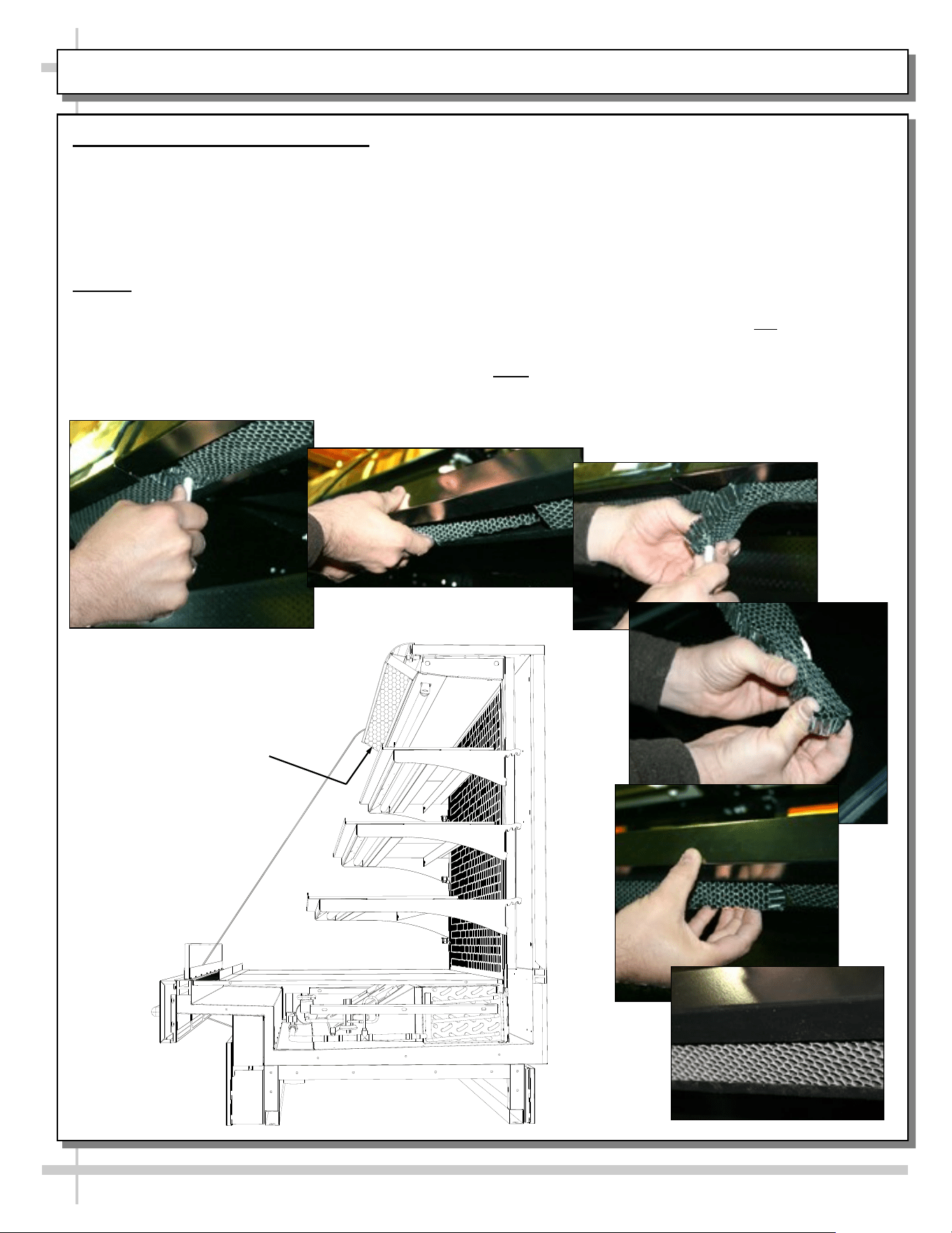
Honeycomb Air Diffuser Removal
See PREVENTIVE MAINTENANCE (TO BE
PERFORMED BY TRAINED SERVICE PROVIDER)
section in this manual for cleaning frequency.
A. Wedge a non-metallic device of suitable strength
(such as a ballpoint pen) between the honeycomb
and the end panel.
Caution! Use care not to dislodge the heating wire
(that prevents condensation on the lamp assembly).
B. Apply pressure to collapse the honeycomb to
allow it to be pulled out of honeycomb retainer.
A
B
C
D
E
F
C. Carefully pry downward and away from the
honeycomb retainer. Clean honeycomb with warm
water and soap solution. Submerse if necessary. Use
brush to dislodge stubborn or sticky residue. Dry by
using vacuum’s blow mode (vs. suction mode).
Honeycomb Air Diffuser Installation
D. Squeeze honeycomb to allow it to fit into the
honeycomb retainer.
E. Carefully slide honeycomb into place.
F. Adjust honeycomb so that it fits flat against
retainer. It must not be wavy or out of position.
Note: For honeycomb air diffusers in other
locations, these same general instructions apply.
Honeycomb
35
SERIAL LABEL LOCATION & INFO LISTED / TECH INFO & SERVICE / REFRIGERATED CASES ONLY
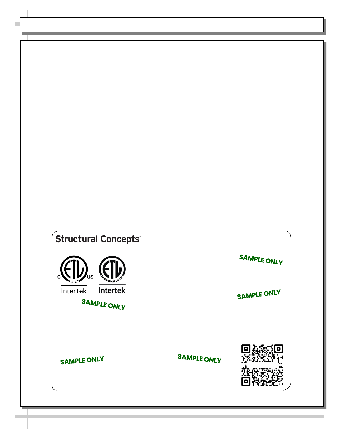
--- Sample Serial Label For Refrigerated Cases ---
MODEL NRS3648RXV-SAMPLE
SERIAL NO. 12345X30DZ098765
TYPE II DISPLAY REFRIGERATOR: THIS EQUIPMENT IS INTENDED FOR USE IN AN AREA
WHERE THE ENVIRONMENTAL CONDITIONS ARE CONTROLLED AND MAINTAINED SUCH
THAT THE AMBIENT TEMPERATURE DOES NOT EXCEED 80 °F (27 °C).
888 E. Porter Rd - Muskegon, MI 49441
3048256
Conforms to UL Std. 471
Conforms to NSF/ANSI Stds. 2 & 7
CERTIFIED TO CAN/CSA
STD C22.2 NO 120
ELECTRICAL RATING
REFRIGERANT
DESIGN PRESSURE
MINIMUM CIRCUIT AMPACITY
MAXIMUM OVERCURRENT
120/1/60 16 A
R513A AMOUNT 50 OZ
HIGH 186 LOW 88
20A
20A
Super Heat Temp 6-8 °F FOR PARTS AND SERVICE
Defrost 6 defrosts per day, 45 °F CALL 1-800-433-9490
Serial Label Location & Information Listed /
Technical Information & Service
• Serial labels are affixed at a wide range of places
(on the header, near thermostat, at case rear,
behind panels/toe-kicks, on electrical boxes, etc.).
• Serial labels contain electrical, temperature and
refrigeration information, as well as regulatory
standards to which the case conforms.
• Sample serial label shown below.
• For additional technical information and service, see
the TECHNICAL SERVICE page in this manual for
instructions on contacting Structural Concepts’
Technical Service Department.
Fusion
Sample QR Code
SCAN FOR PRODUCT LITERATURE
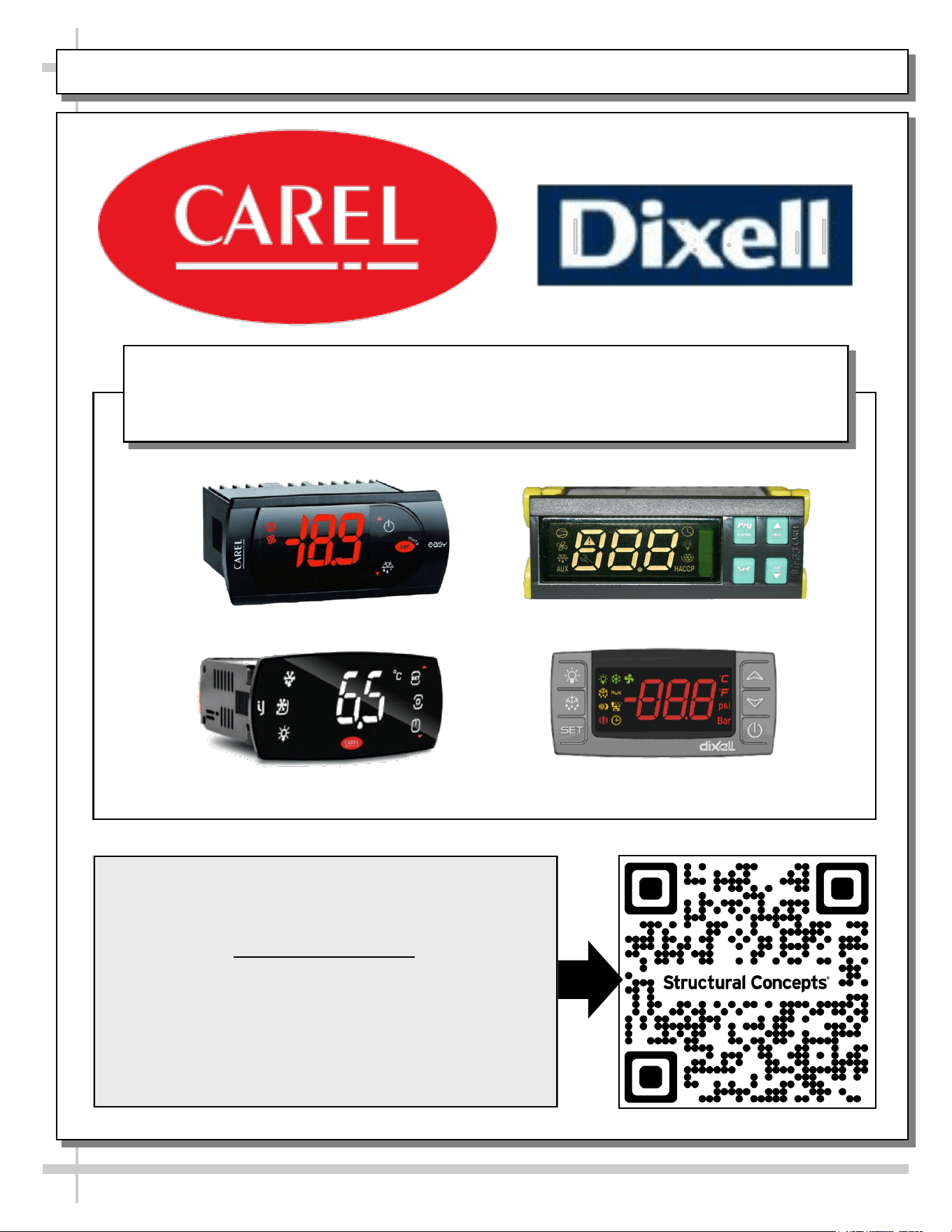
PROGRAMMABLE CONTROLLER (SELECT, CLICK ON OR SCAN QR CODE FOR INFORMATION)
36
Carel® iJF Platform
Carel® PJEZ Platform
Carel® ir33 Platform
Dixell® XM670K-XM679K Platform
To Access Information About The Programmable
Controller That Is Used On Your Case,
Follow These Instructions:
> If Viewing This Document on Smart Phone, Tablet
or Computer, Select/Click On The QR Code at Right.
> If Viewing This Document In Print (Hard Copy),
Scan The QR Code at Right With Your Smart Phone
or Tablet.
Determine Which Programmable Controller Is On Your Case (Controllers
That Are Commonly Used By Structural Concepts Are Shown Below).
Your Particular Programmable Controller May Differ.
STRUCTURAL CONCEPTS TECHNICAL SERVICE CONTACT INFORMATION & LIMITED WARRANTY
37
TECH SERVICE/WARRANTY CONTACT INFO:
1 (800) 433-9490 / EXTENSION 1
DAYS/HOURS AVAILABLE:
MONDAY - FRIDAY (CLOSED HOLIDAYS)
8:00 A.M. to 5:00 P.M. EST
YOU MUST HAVE THE FOLLOWING INFO AVAILABLE
BEFORE CONTACTING STRUCTURAL CONCEPTS:
SERIAL NO. / MODEL NO. / STORE NO. / STORE
ADDRESS / DETAILS (PHOTOS, LEAK LOCATIONS,
DAMAGE, STORE’S AMBIENT CONDITIONS, ETC.)
To Access The Limited Warranty To Your
Case, Follow These Instructions:
> If Viewing This Document on Smart Phone,
Tablet or Computer, Select/Click On The QR
Code at Right.
> If Viewing This Document In Print (Hard
Copy), Scan The QR Code at Right With Your
Smart Phone or Tablet.