
M490000/M540000/M610000 Repair Manual
80021828 (Revision A)
BRIGGS&STRAT TON, LLC
CUSTOMER EDUCATION
Milwaukee, WI 53201 USA
Copyright ©2020. All rights reserved.
VANGUARDPOWER.COM
Vanguard
®
BIG BLOCK
™
and 810
EFI Diagnostic and Repair
M490000/M540000/M610000
REPAIR MANUAL
Not for
Reproduction

Not for
Reproduction

Foreword
This manual was written to assist engine technicians and service personnel with the troubleshooting
and repair procedures for Briggs & Stratton® engines equipped with Electronic Fuel Injection (EFI). It
assumes that persons using this manual have been properly trained and are familiar with the service
procedures for these products, including the proper use of required tools and the application of
appropriate safety practices. Persons untrained or unfamiliar with these procedures or products should
not attempt to perform such work.
Proper repair is important to safe, reliable operation of all engines and engine-driven systems. The
troubleshooting and repair procedures described in this manual are appropriate for the Briggs & Stratton
engines described herein. Alternative methods or procedures may pose risks to both personal safety and
engine reliability and are not endorsed or recommended by Briggs & Stratton.
All information, illustrations, and specifications contained in this manual were based on the data available
at the time of publication. Briggs & Stratton, LLC reserves the right to change, alter, or otherwise improve
the product or the product manuals at any time without prior notice.
Copyright © 2020 Briggs & Stratton, LLC.
All rights reserved.
No part of this manual may be reproduced or transmitted in any form or by any means, electronic or
mechanical, including photocopying or recording by any information storage and retrieval system, without
prior written permission from Briggs & Stratton, LLC.
Not for
Reproduction

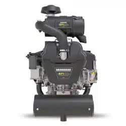
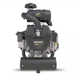
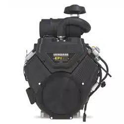
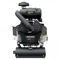
This engine troubleshooting and repair manual includes the following EFI equipped engine models:
• MODEL 490000
• MODEL 540000
• MODEL 610000
NOTE: Some models have limited service parts. Review theIllustrated
Parts Listfor part availability before conducting any service work.
NOTE: The images in this document are representative and may differ according to model.
Not for
Reproduction

SECTION 1 - DIAGNOSTIC INTRODUCTION
1
SECTION 2 - TROUBLESHOOTING DTCs
2
SECTION 3 - WIRE SCHEMATICS AND PIN-OUTS
3
SECTION 4 - SYMPTOMS
4
SECTION 5 - REMOVAL/INSTALLATION
5
Not for
Reproduction

Not for
Reproduction

1
3
SECTION 1 - DIAGNOSTIC INTRODUCTION
DIAGNOSTIC INTRODUCTION ----------------------------------------------------------------------------------------------------------------- 4
On-Board Diagnostic (OBD) System Check -------------------------------------------------------------------------------------------- 4
Diagnostic Trouble Codes (DTCs) --------------------------------------------------------------------------------------------------------- 4
Malfunction Indicator Lamp (MIL) ---------------------------------------------------------------------------------------------------------- 4
Data Link Connector (DLC) ------------------------------------------------------------------------------------------------------------------4
Non-Scan Diagnostics -------------------------------------------------------------------------------------------------------------------------4
Scan Diagnostics ------------------------------------------------------------------------------------------------------------------------------- 4
Use MIL to Read DTCs ---------------------------------------------------------------------------------------------------------------------- 4
Use Tiny Scan Code Reader to Read/Clear DTCs ----------------------------------------------------------------------------------- 5
Use Diagnostic Tool to Read/Clear DTCs -----------------------------------------------------------------------------------------------5
Back Probe Connector Terminals ----------------------------------------------------------------------------------------------------------6
Avoid ECM Damage ---------------------------------------------------------------------------------------------------------------------------6
Special Tools ------------------------------------------------------------------------------------------------------------------------------------ 7
Product Improvements/Field Upgrades --------------------------------------------------------------------------------------------------- 8
Not for
Reproduction

1
4
DIAGNOSTIC INTRODUCTION
On-Board Diagnostic (OBD) System Check
The basic steps of any diagnosis are as follows:
1. Observe the Malfunction Indicator Lamp (MIL) with
engine running. If MIL is illuminated, then current
Diagnostic Trouble Codes (DTCs) are present.
2. Read DTC(s) using MIL, Tiny Scan Code Reader,
orDiagnostic Toolsoftware.
3. To diagnose system problem(s), proceed to the
applicable Diagnostic Table(s) inSECTION 2 -
TROUBLESHOOTING DTCs.
4. Once the problem is located and corrected through
repair or replacement of faulty components, clear
DTC(s) using the Tiny Scan Code Reader or
theDiagnostic Toolsoftware.
NOTE:For information on the location or
replacement of specific components, seeSECTION 5
- REMOVAL/INSTALLATION.
5. Start and run engine to validate repairs. Observe MIL
to verify that no DTCs are set.
6. If no DTCs are set, but engine performance issues
exist, seeSECTION 4 - SYMPTOMS.
Diagnostic Trouble Codes (DTCs)
The ECM receives voltage signals from as many as five
sensors. Each sensor functions within an established
set of parameters, which can be viewed as its operating
“window.”
When a malfunction or fault condition occurs, a change
in the signal voltage alerts the ECM that the sensor is
functioning outside its operating “window,” a DTC is set
and stored in ECM memory, and the MIL is illuminated.
A default value temporarily replaces the erroneous sensor
value to restore engine performance until the problem is
corrected.
Malfunction Indicator Lamp (MIL)
As a bulb and diagnostic system check, the MIL
illuminates at Ignition ON, Engine OFF. When the engine
is started, the MIL is extinguished if no current fault
condition exists.
If the MIL remains illuminated, it is an indication that a
current DTC is stored. If the fault should correct itself, as
in an intermittent condition, the MIL is extinguished after
a ten second delay. The DTC remains stored in ECM
memory as a historic code until cleared by the technician.
The MIL does not indicate the existence of only historic
codes.
Data Link Connector (DLC)
The DLC provides for direct communication with the
ECM. By plugging the Tiny Scan Code Reader, or laptop
withDiagnostic Tool, into the 6-pin connector in the EFI
wire harness, the DTCs stored in ECM memory can be
read and cleared.
Non-Scan Diagnostics
In the Non-Scan diagnostic mode, either the MIL or
the Tiny Scan Code Reader is used to read DTCs. The
technician then refers to the applicable Diagnostic Table
to troubleshoot the problem. Those tables labeledNon-
Scan Diagnosticsmust be used, as the data stream
provided by the ECM is not available for analysis.
Scan Diagnostics
In the more sophisticated diagnostic mode, theDiagnostic
Toolsoftware can facilitate the diagnosis of system
problems through an expanded interface with the ECM.
Through the use of data displays and menu selections,
the technician has access to “live” data for analysis.
It is important to note that the software is not a stand-
alone diagnostic tool for resolving DTCs, but must be
used in conjunction with the Diagnostic Tables for the
most efficient and effective diagnosis. Those tables that
are applicable to users with access to theDiagnostic
Toolsoftware are labeled asScan Diagnostics.
Use MIL to Read DTCs
1. Verify that battery voltage is above 12v.
2. Turn Ignition key OFF for ten seconds.
3. Turn Ignition key ON-OFF-ON-OFF-ON (but do not
start the engine).
NOTE:No more than 2.5 seconds can elapse
between each ON and OFF cycle or the routine is
aborted.
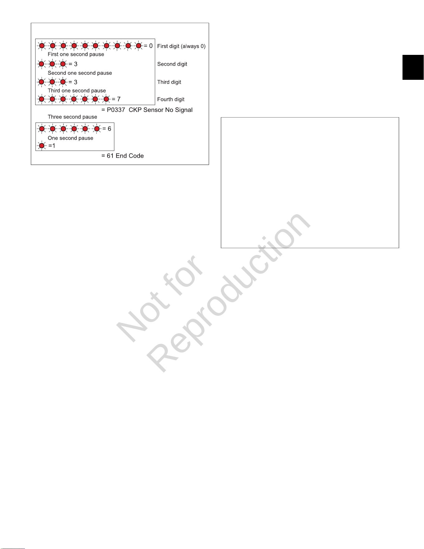
4. When performed correctly, the MIL begins to flash the
first of four digits.
NOTE:While each DTC actually begins with the
letter “P,” only the numeric characters are flashed.
5. Count the number of flashes to obtain the first of four
digits. If the first digit is zero, it is represented as a
series of ten flashes.
Not for
Reproduction
1
5
1
6. Count the number of flashes after the first one second
pause to obtain the second digit of the DTC.
7. Count the number of flashes after the second one
second pause to obtain the third digit, and then count
the number of flashes after the third one second
pause to obtain the fourth digit.
8. Write down each digit as it is displayed.
9. If there is more than one DTC, the next DTC begins
to flash after a three second pause.
10. After all DTCs are reported, the number “61” is
flashed to indicate this condition to the technician.
The flashing sequence is then restarted and the
technician may choose to verify the DTCs written
down or exit the routine.
NOTE:If “61” is the first code flashed, then no active
DTCs are set.
Use Tiny Scan Code Reader to Read/Clear
DTCs
NOTE:Always follow steps 1-9 for an accurate report of
current DTCs. Failure to do so may generate a report that
includes historic codes.
1. Obtain Briggs & Stratton Tiny Scan Code Reader
(Part No. 19626).
2. Connect code reader to DLC.
3. Turn Ignition ON, Engine OFF.
NOTE:If the Tiny Scan Code Reader cannot connect
to the ECM, “no-C” is displayed, which stands for “no
communication.” If communication is established, the
tool displays the number of DTCs read. For example,
“dc-0” means that no DTCs were found, while “dc-4”
means that four DTCs are recorded.
4. Press the select button to cycle through the list of
DTCs.
5. Once the last DTC is displayed, “CLr?” appears.
Press and hold the select button until “Hold” changes
to “Done,” which indicates that all DTCs have been
“cleared” from ECM memory.
6. Turn Ignition OFF for a minimum of 20 seconds.
7. Turn Ignition ON, Engine OFF.
8. The tool displays the number of DTCs read.
9. Press the select button to cycle through the list of
DTCs. Write down each DTC as it is displayed.
2
Use Diagnostic Tool to Read/Clear DTCs
1. Obtain Briggs & Stratton Diagnostic Tool (Part No.
19636) with USB and Interface cables.
2. Connect one end of the USB cable to the Diagnostic
Tool and the other end to the USB port on the laptop.
3. Connect one end of the Interface cable to the
Diagnostic Tool and the other end to the DLC on the
EFI harness.
4. Turn Ignition ON, Engine OFF. The Diagnostic Tool
can take up to 30 seconds to connect to the engine.
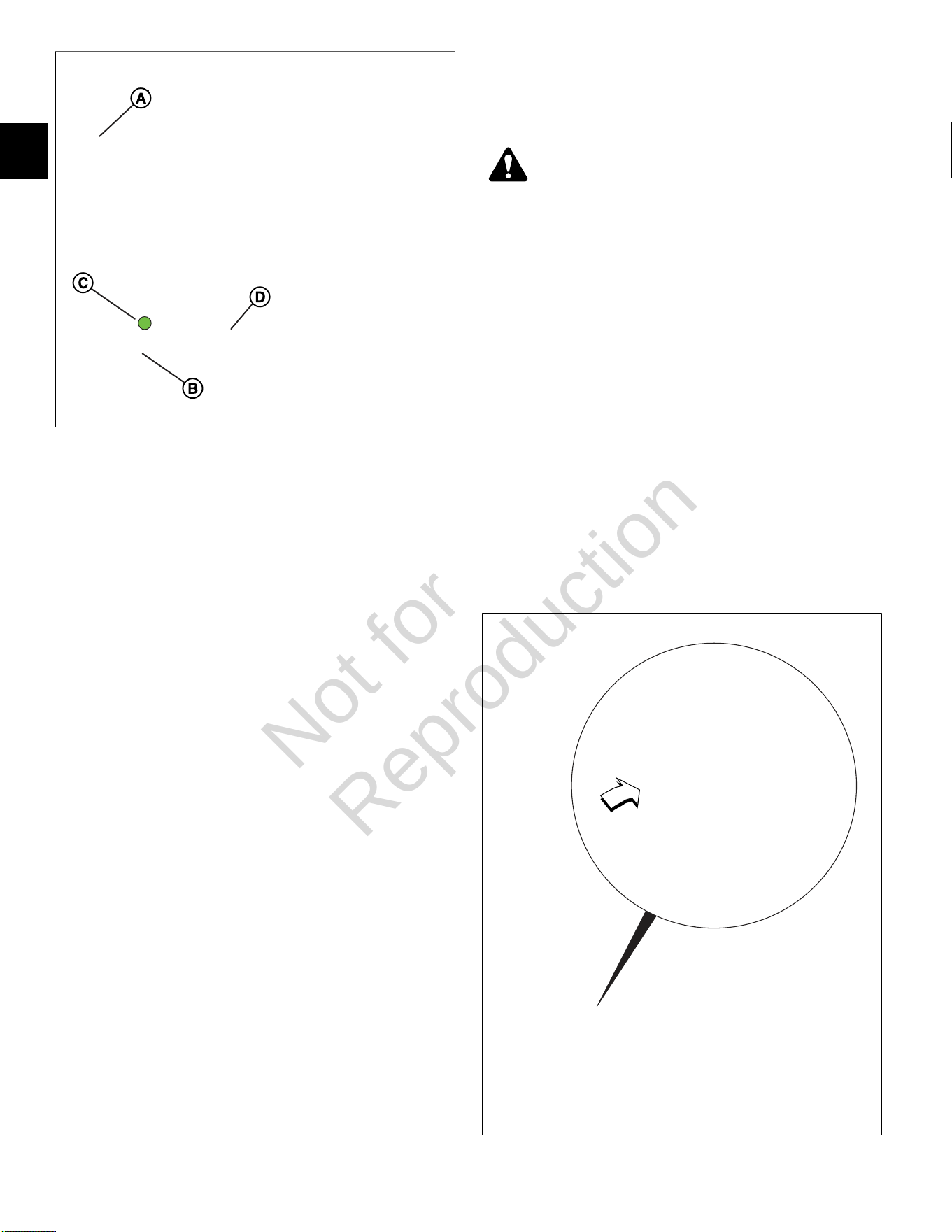
5. See Figure3. Select theDashboardicon (A) in the
left sidebar to view theDealertab.
6. Observe the Current codes display (B).
NOTE:TheCHECK ENGINElight (C) is green if a
current fault code is present. To display a description
of the fault code, hover the cursor over the code.
NOTE:A Current codes display can also be viewed
under theTroubleshootingtab.
7. ClickClear(D) to erase both current and historic
DTCs.
NOTE:See the Briggs & Stratton EFI Diagnostic Tool
Software User Manual for more information.
8. Turn Ignition OFF.
Not for
Reproduction
1
6
3
Back Probe Connector Terminals
NOTE:Do not insert probes into terminals on the mating
side of any connector. The diameter of the test probes
can damage terminals.
1. Obtain Briggs & Stratton Back Probe Wire Set (Part
No. 19625).
2. Carefully slide metal pin on probe between the rubber
seal and wire insulation on the back side (wire end) of
the connector.
3. Gently push the pin in until it stops. Stop pushing
when the pin “bottoms out,” or when the plastic
sheath is very close to the connector housing.
DO NOTforce the pin into the connector as terminal
and/or probe pin damage can occur. Probe travel
may be stopped by contact with insulation or core
crimps. Try again after removing and re-positioning
probe pin.
IMPORTANT:
• Use care to avoid deforming connector terminals,
either by forcing the probe too far into the cavity
or by using a probe that is too large. If terminal
damage is suspected, test for proper terminal
contact.
• A deformed terminal can cause a poor
connection resulting in intermittent problems or
even complete component failure. Do not use
paper clips or other substitute devices as they
also can damage terminals.
• Do not probe through connector seals, wire
insulation, secondary ignition wires, boots, etc.
Damage can occur that is not readily apparent
and tiny holes can result in water intrusion, which
leads to corrosion and eventual component
failure.
Avoid ECM Damage
CAUTION
A surge in voltage, current or both, is called a
voltage spike. Voltage spikes can cause major
damage to the ECM.
1. To avoid ECM failure due to accidentally induced
voltage spikes, always observe the following
precautions:
• Do not start engine if battery cable connections
are loose.
• Do not use a battery charger to start engine.
• Turn Ignition OFF before disconnecting and/or
connecting battery cables.
• When disconnecting battery, always disconnect
battery negative (-) cable first.
• When connecting battery, always connect battery
positive (+) cable first.
• When charging battery, turn Ignition OFF and
remove battery negative cable (black) from
battery negative (-) terminal.
4
Not for
Reproduction
1
7
• If electric welding on vehicle, remove battery
negative cable (black) from battery negative
(-) terminal, and disconnect the ECM electrical
connector(s). If welding on the muffler, also
disconnect the O
2
sensor electrical connector and
remove the O
2
sensor from the muffler.
2. Do not spray water at or around ECM.
NOTE:See Figure4. A pin hole centered under the
adhesive label is used in manufacturing to determine
the integrity of the potted seal. If the label peels or
becomes torn, worn or abraded, exposure of the hole
can allow water or moisture to intrude, leading to
corrosion and eventual ECM failure.
Special Tools
The following special tools are required:
1. Briggs & Stratton Spark Tester (Part No. 19368).
2. Briggs & Stratton Digital Volt Ohmmeter Extech
Ma220 (Part No. 19602).
3. Briggs & Stratton Noid Light (Part No. 19623).
4. Briggs & Stratton BIG BLOCK™ Fuel Pressure Test
Adapter (Part No. 19624).
5. Briggs & Stratton Back Probe Wire Set (Part No.
19625).
6. Briggs & Stratton Tiny Scan Code Reader (Part No.
19626).
7. Briggs & Stratton Fuel Pressure Gauge (Part No.
19627).
8. Briggs & StrattonDiagnostic Tool Kit (Part No.
19636).
Not for
Reproduction

1
8
Product Improvements/Field Upgrades
The following Service Bulletins provide information on
product improvements recently introduced in production.
Service kits are available for upgrading product in the
field.
ServiceBulletin CSB-1030
For protection against voltage spikes on Model 610000
marine engines having the 20/50 amp charging system,
install the Briggs & Stratton Capacitor Kit (Part No.
847148).
ServiceBulletin DSB-1053
To dampen vibration to the ECM/fuse block bracket,
install Briggs & Stratton Service Kit (Part No. 847337),
which includes a new fuse/relay block cover, ECM
mounting bracket, rubber isolation mounts, and mounting
hardware.
ServiceBulletin Access
To access a bulletin, proceed as follows:.
• Go to www.thepowerportal.com.
• Enter Login and Password.
• From the home page, select the “Technical
Information” tab.
• Select “Service Bulletins.”
• Under “Keyword,” type in the bulletin number.
• Select “View.”
Not for
Reproduction

2
9
SECTION 2 - TROUBLESHOOTING DTCS
DIAGNOSTIC TROUBLE CODES (DTCS) --------------------------------------------------------------------------------------------------12
MODEL 490000 EFI COMPONENT LOCATIONS ---------------------------------------------------------------------------------------- 13
MODELS 540000/610000 EFI COMPONENT LOCATIONS --------------------------------------------------------------------------- 14
VERIFY ECM POWERS UP -------------------------------------------------------------------------------------------------------------------- 15
Circuit Description ---------------------------------------------------------------------------------------------------------------------------- 15
Check ECM Power and Grounds (Non-Scan Diagnostics) ------------------------------------------------------------------------ 15
DTC P0031/P0032 OXYGEN SENSOR (HO2) HEATER ------------------------------------------------------------------------------- 17
Circuit Description ---------------------------------------------------------------------------------------------------------------------------- 17
Diagnostic Aids -------------------------------------------------------------------------------------------------------------------------------- 17
DTC P0031 Signal Voltage Low (Non-Scan Diagnostics) ------------------------------------------------------------------------- 18
DTC P0032 Signal Voltage High (Non-Scan Diagnostics) -------------------------------------------------------------------------19
DTC P0107/P0108 MANIFOLD ABSOLUTE PRESSURE (MAP) SENSOR ------------------------------------------------------- 20
Circuit Description ---------------------------------------------------------------------------------------------------------------------------- 20
Diagnostic Aids -------------------------------------------------------------------------------------------------------------------------------- 20
DTC P0107 Signal Voltage Low or Open (Scan Diagnostics) --------------------------------------------------------------------21
DTC P0107 Signal Voltage Low or Open (Non-Scan Diagnostics) --------------------------------------------------------------22
DTC P0108 Signal Voltage High (Scan Diagnostics) ------------------------------------------------------------------------------- 24
DTC P0108 Signal Voltage High (Non-Scan Diagnostics) -------------------------------------------------------------------------25
DTC P0112/P0113 MANIFOLD AIR TEMPERATURE (MAT) SENSOR ------------------------------------------------------------ 26
Circuit Description ---------------------------------------------------------------------------------------------------------------------------- 26
Diagnostic Aids -------------------------------------------------------------------------------------------------------------------------------- 26
DTC P0112 Signal Voltage Low (Scan Diagnostics) --------------------------------------------------------------------------------27
DTC P0112 Signal Voltage Low (Non-Scan Diagnostics) ------------------------------------------------------------------------- 28
DTC P0113 Signal Voltage High or Open (Scan Diagnostics) ------------------------------------------------------------------- 29
DTC P0113 Signal Voltage High or Open (Non-Scan Diagnostics) ------------------------------------------------------------- 30
DTC P0117/P0118 ENGINE HEAD TEMPERATURE (EHT) SENSOR ------------------------------------------------------------- 31
Circuit Description ---------------------------------------------------------------------------------------------------------------------------- 31
Diagnostic Aids -------------------------------------------------------------------------------------------------------------------------------- 31
DTC P0117 Signal Voltage Low (Scan Diagnostics) --------------------------------------------------------------------------------32
DTC P0117 Signal Voltage Low (Non-Scan Diagnostics) ------------------------------------------------------------------------- 33
DTC P0118 Signal Voltage High or Open (Scan Diagnostics) ------------------------------------------------------------------- 34
DTC P0118 Signal Voltage High or Open (Non-Scan Diagnostics) ------------------------------------------------------------- 35
DTC P0122/P0123 THROTTLE POSITION SENSOR (TPS) -------------------------------------------------------------------------- 36
Circuit Description ---------------------------------------------------------------------------------------------------------------------------- 36
Diagnostic Aids -------------------------------------------------------------------------------------------------------------------------------- 36
Not for
Reproduction

2
10
DTC P0122 Signal Voltage Low or Open (Scan Diagnostics) --------------------------------------------------------------------37
DTC P0122 Signal Voltage Low or Open (Non-Scan Diagnostics) --------------------------------------------------------------38
DTC P0123 Signal Voltage High (Scan Diagnostics) ------------------------------------------------------------------------------- 39
DTC P0123 Signal Voltage High (Non-Scan Diagnostics) -------------------------------------------------------------------------40
DTC P0131/P0132 OXYGEN (HO2) SENSOR -------------------------------------------------------------------------------------------- 41
Circuit Description ---------------------------------------------------------------------------------------------------------------------------- 41
Diagnostic Aids -------------------------------------------------------------------------------------------------------------------------------- 17
DTC P0131 Signal Voltage Low (Scan Diagnostics) --------------------------------------------------------------------------------42
DTC P0131 Signal Voltage Low (Non-Scan Diagnostics) ------------------------------------------------------------------------- 43
DTC P0132 Signal Voltage High (Scan Diagnostics) ------------------------------------------------------------------------------- 44
DTC P0132 Signal Voltage High (Non-Scan Diagnostics) -------------------------------------------------------------------------45
DTC P0174 POWER ENRICHMENT (PE) -------------------------------------------------------------------------------------------------- 46
Circuit Description ---------------------------------------------------------------------------------------------------------------------------- 46
Diagnostic Aids -------------------------------------------------------------------------------------------------------------------------------- 46
DTC P0174 Lean Fuel Condition (Non-Scan Diagnostics) ------------------------------------------------------------------------ 46
DTC P0201/P0202 CYLINDER 1 OR CYLINDER 2 FUEL INJECTOR --------------------------------------------------------------47
Circuit Description ---------------------------------------------------------------------------------------------------------------------------- 47
Diagnostic Aids -------------------------------------------------------------------------------------------------------------------------------- 47
DTC P0201 Cylinder 1 Fuel Injector Fault (Non-Scan Diagnostics) -------------------------------------------------------------48
DTC P0202 Cylinder 2 Fuel Injector Fault (Non-Scan Diagnostics) -------------------------------------------------------------50
DTC P0230/P0232 FUEL PUMP FAULT ---------------------------------------------------------------------------------------------------- 52
Circuit Description ---------------------------------------------------------------------------------------------------------------------------- 52
Diagnostic Aids -------------------------------------------------------------------------------------------------------------------------------- 52
DTC P0230 Signal Voltage Low or Open (Non-Scan Diagnostics) --------------------------------------------------------------53
DTC P0232 Signal Voltage High (Non-Scan Diagnostics) -------------------------------------------------------------------------54
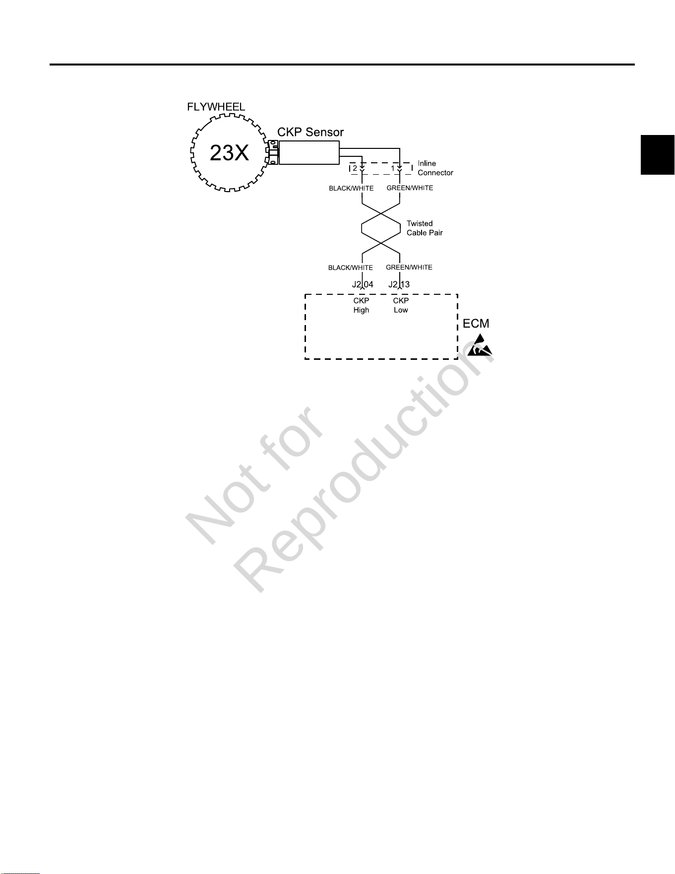
DTC P0336/P0337 CRANKSHAFT POSITION (CKP) SENSOR ----------------------------------------------------------------------55
Modes of Operation -------------------------------------------------------------------------------------------------------------------------- 55
Diagnostic Aids -------------------------------------------------------------------------------------------------------------------------------- 55
DTC P0336 Signal Voltage Noisy (Scan Diagnostics) ------------------------------------------------------------------------------56
DTC P0336 Signal VoltageNoisy (Non-Scan Diagnostics) ------------------------------------------------------------------------57
DTC P0337 Signal Voltage Absent (Scan Diagnostics) ---------------------------------------------------------------------------- 58
DTC P0337 Signal VoltageAbsent (Non-Scan Diagnostics) ----------------------------------------------------------------------59
DTC P0351/P0352 CYLINDER 1 OR CYLINDER 2 IGNITION COIL FAULT ------------------------------------------------------60
Circuit Description ---------------------------------------------------------------------------------------------------------------------------- 60
Diagnostic Aids -------------------------------------------------------------------------------------------------------------------------------- 47
DTC P0351 Cylinder 1 Ignition Coil Fault (Non-Scan Diagnostics) ------------------------------------------------------------- 61
DTC P0352 Cylinder 2 Ignition Coil Fault (Non-Scan Diagnostics) ------------------------------------------------------------- 62
DTC P0505 IDLE AIR CONTROL (IAC) MALFUNCTION -------------------------------------------------------------------------------63
Circuit Description ---------------------------------------------------------------------------------------------------------------------------- 63
Diagnostic Aids -------------------------------------------------------------------------------------------------------------------------------- 63
Not for
Reproduction

2
11
DTC P0505 Idle Air Control (IAC) Malfunction (Scan Diagnostics) --------------------------------------------------------------64
DTC P0505 Idle Air Control (IAC) Malfunction (Non-Scan Diagnostics) ------------------------------------------------------- 65
DTC P0562/P0563 SYSTEM VOLTAGE ---------------------------------------------------------------------------------------------------- 66
Circuit Description ---------------------------------------------------------------------------------------------------------------------------- 66
Diagnostic Aids -------------------------------------------------------------------------------------------------------------------------------- 66
DTC P0562 System Voltage Low (Scan Diagnostics) ------------------------------------------------------------------------------ 67
DTC P0562 System Voltage Low (Non-Scan Diagnostics) ------------------------------------------------------------------------68
DTC P0563 System Voltage High (Scan Diagnostics) ----------------------------------------------------------------------------- 70
DTC P0563 System Voltage High (Non-Scan Diagnostics) ----------------------------------------------------------------------- 70
DTC P0650 MALFUNCTION INDICATOR LAMP (MIL) MALFUNCTION ----------------------------------------------------------- 71
Circuit Description ---------------------------------------------------------------------------------------------------------------------------- 71
Diagnostic Aids -------------------------------------------------------------------------------------------------------------------------------- 71
DTC P0650 MIL Malfunction (Scan Diagnostics) ------------------------------------------------------------------------------------ 72
DTC P0650 MIL Malfunction (Non-Scan Diagnostics) ------------------------------------------------------------------------------ 73
DTC P1693/P1694TACHOMETER MALFUNCTION -------------------------------------------------------------------------------------74
Diagnostic Aids -------------------------------------------------------------------------------------------------------------------------------- 74
DTC P1693 Driver Circuit Shorted to Ground (Non-Scan Diagnostics) -------------------------------------------------------- 75
DTC P1694 Driver Circuit Shorted to Power (Non-Scan Diagnostics) ----------------------------------------------------------76
Not for
Reproduction

2
12
DIAGNOSTIC TROUBLE CODES (DTCS)
Component DTC Description
P0031 Signal Voltage LowOxygen (O
2
) Sensor Heater
P0032 Signal Voltage High
P0107 Signal Voltage Low or OpenManifold Absolute Pressure (MAP) Sensor
P0108 Signal Voltage High
P0112 Signal Voltage LowManifold Air Temperature (MAT) Sensor
P0113 Signal Voltage High or Open
P0117 Signal Voltage LowEngine Head Temperature (EHT) Sensor
P0118 Signal Voltage High or Open
P0122 Signal Voltage Low or OpenThrottle Position Sensor (TPS)
P0123 Signal Voltage High
P0131 Signal Voltage LowOxygen (O
2
) Sensor
P0132 Signal Voltage High
Power Enrichment (PE) Mode P0174 Lean Fuel Condition
Cylinder 1 Fuel Injector P0201 Cylinder 1 Fuel Injector Fault
Cylinder 2 Fuel Injector P0202 Cylinder 2 Fuel Injector Fault
P0230 Signal Voltage Low or OpenFuel Pump Fault
P0232 Signal Voltage High
P0336 Signal Voltage NoisyCrankshaft Position (CKP) Sensor
P0337 Signal Voltage Absent
Cylinder 1 Ignition Coil P0351 Cylinder 1 Ignition Coil Fault
Cylinder 2 Ignition Coil P0352 Cylinder 2 Ignition Coil Fault
Idle Air Control (IAC) P0505 IAC Malfunction
P0562 System Voltage LowSystem Voltage
P0563 System Voltage High
Malfunction Indicator Lamp (MIL) P0650 MIL Circuit Malfunction
P1693 Driver Circuit Shorted to GroundTachometer
P1694 Driver Circuit Shorted to Power
Model 610000Component Model 490000 Model 540000
Turf Marine
IAC - - - *
HO
2
Sensor * * * -
TPS - - - *
* = Equipped
Not for
Reproduction
2
13
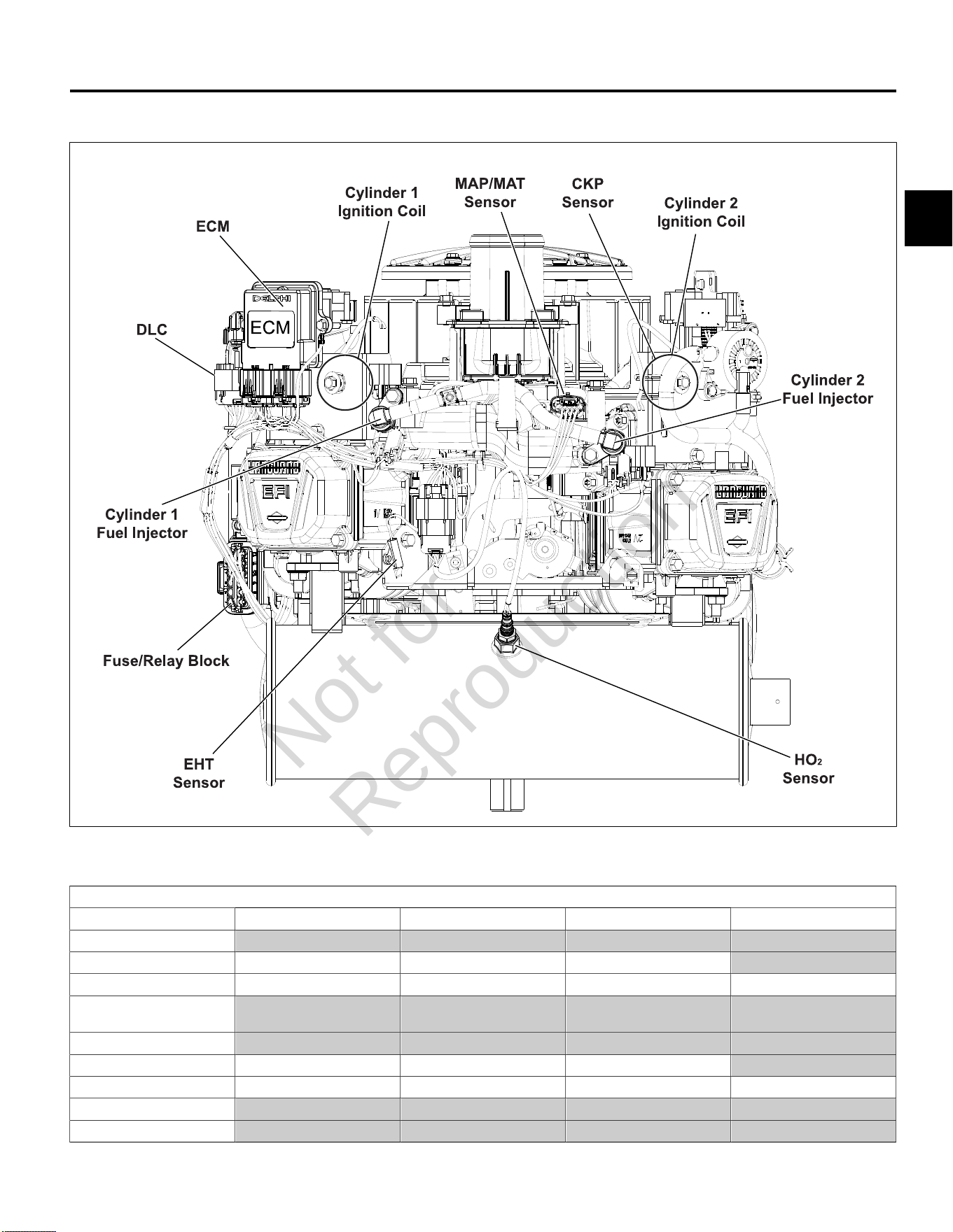
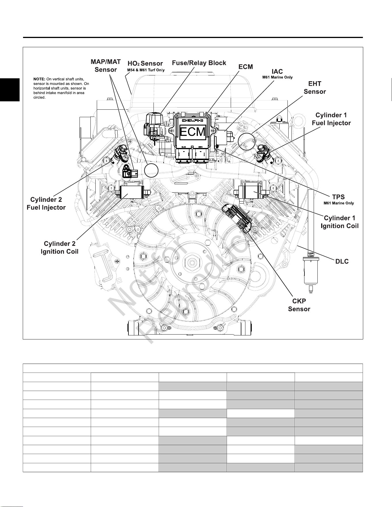
MODEL 490000 EFI COMPONENT LOCATIONS
5
NOTE:Static guard, decorative cover, and blower housing removed for illustration purposes.
Removal Required for Back Probing Connector (x) or Replacing Component (o)
To Access Air Cleaner Assembly Static Guard Decorative Cover Blower Housing
ECM
MAP/MAT Sensor xo xo xo
Ignition Coil o o o o
Mechanical
Diaphragm Fuel Pump
Fuel Pump Module
Fuel Injectors o o o
CKP Sensor xo xo xo xo
HO
2
Sensor
Fuse/Relay Block
NOTE:SeeSECTION 5 - REMOVAL/INSTALLATIONfor instructions.
Not for
Reproduction
2
14
MODELS 540000/610000 EFI COMPONENT LOCATIONS
6
NOTE:Access cover and blower housing removed for illustration purposes.
Removal Required for Back Probing Connector (x) or Replacing Component (o)
To Access Access Cover Blower Housing Air Cleaner Assembly Throttle Body
ECM xo
MAP/MAT Sensor xo xo
Ignition Coil xo xo
Fuel Pump Module xo xo
Fuel Injectors xo xo
CKP Sensor xo xo
TPS xo xo o
IAC xo xo
HO
2
Sensor xo xo
Fuse/Relay Block xo
NOTE:SeeSECTION 5 - REMOVAL/INSTALLATIONfor instructions.
Not for
Reproduction

2
15
VERIFY ECM POWERS UP
Circuit Description
Since all EFI components are dependent on proper
operation of the ECM, any diagnosis must include
checking ECM power and grounds.
Remove and clean battery terminals. While terminals may
appear clean, corrosion on the inner surfaces can cause
a poor connection to ground.
NOTE:When the ECM is powered up, you may hear
the fuel pump module prime for two seconds. This is not
definitive proof that the ECM is getting proper voltage.
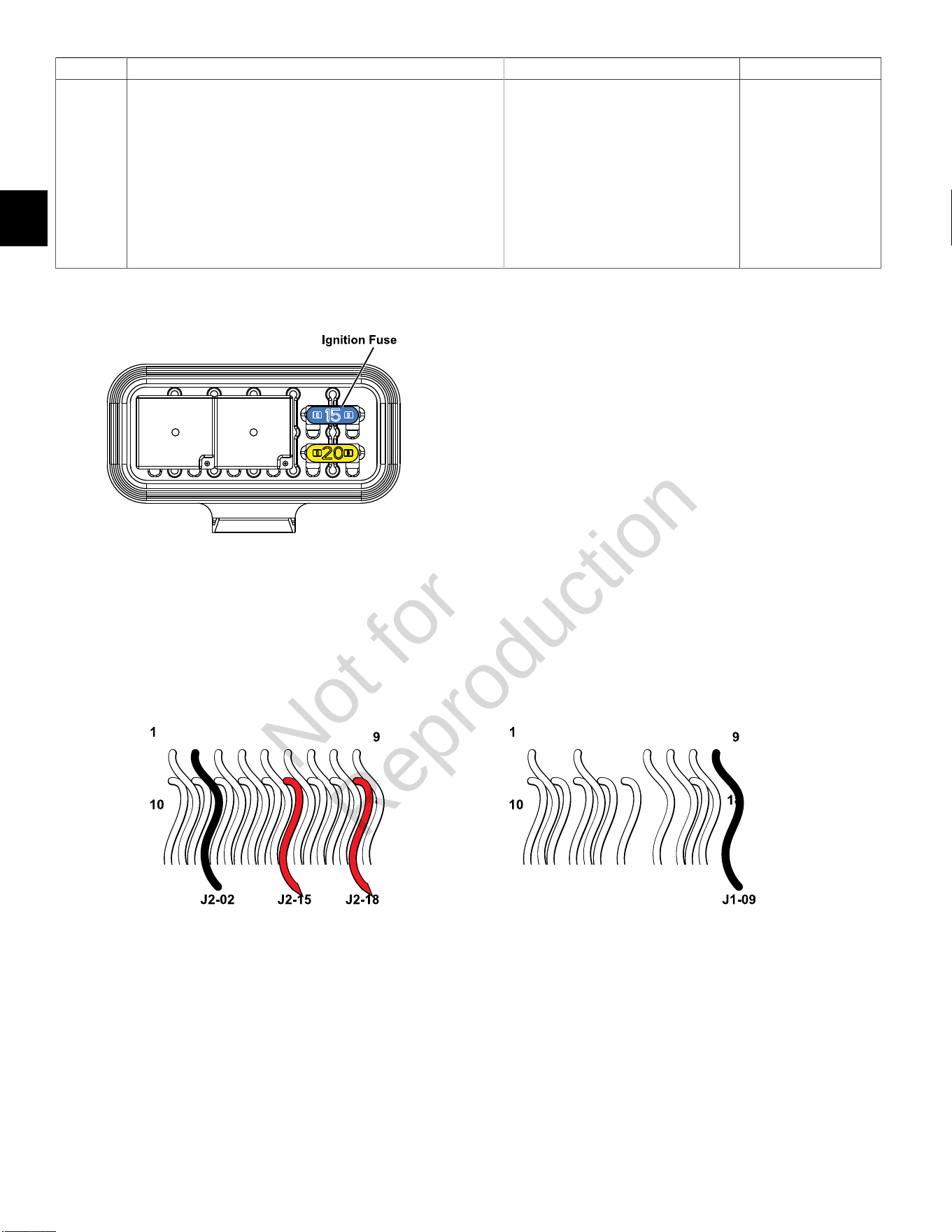
Check ECM Power and Grounds (Non-Scan Diagnostics)
Step Action Yes No
1 1. Turn Ignition OFF.
2. Back probe terminal J2-18 (Red wire) of ECM J2 (Black)
connector.
3. Connect terminal J2-18 back probe to red meter test lead on
DVOM.
4. Connect black meter test lead on DVOM to a known good
ground.
5. Set DVOM to read volts DC.
6. Turn Ignition ON, Engine OFF.
7. Observe voltage on DVOM.
8. Is reading 12.2-14.5 volts DC?
Go to step 2. Look for open or short
to ground in battery
(B+) feed circuit.
Perform visual and
continuity check of
15 amp Ignition fuse
(Blue).
2 1. Turn Ignition OFF.
2. Remove probe from terminal J2-18, and back probe terminal
J2-15 (Red wire) of ECM J2 connector.
3. Connect terminal J2-15 back probe to red meter test lead on
DVOM.
4. Connect black meter test lead on DVOM to a known good
ground.
5. Turn Ignition ON, Engine OFF.
6. Observe voltage on DVOM.
7. Is reading 12.2-14.5 volts DC?
Go to step 3. Look for open or
short to ground in
ignition feed circuit.
3 1. Turn Ignition OFF.
2. Remove probe from terminal J2-15, and back probe terminal
J2-02 (Black wire) of ECM J2 connector.
3. Connect terminal J2-02 back probe to red meter test lead on
DVOM.
4. Connect black meter test lead on DVOM to a known good
ground.
5. Set DVOM to read resistance.
6. Observe reading on DVOM.
7. Is resistance 1.0 ohm or less?
Go to step 4. Look for open or short
in ECM ground circuit.
Continued...
Not for
Reproduction
2
16
Step Action Yes No
4 1. Remove probe from terminal J2-02, and back probe terminal
J1-09 (Black wire) of ECM J1 (Grey) connector.
2. Connect terminal J1-09 back probe to red meter test lead on
DVOM.
3. Connect black meter test lead on DVOM to a known good
ground.
4. Observe reading on DVOM.
5. Is resistance 1.0 ohm or less?
System OK. Look for open or short
in ECM ground circuit.
Fuse/Relay Block
ECM J2 (Black) Connector ECM J1 (Grey) Connector
Not for
Reproduction

2
17
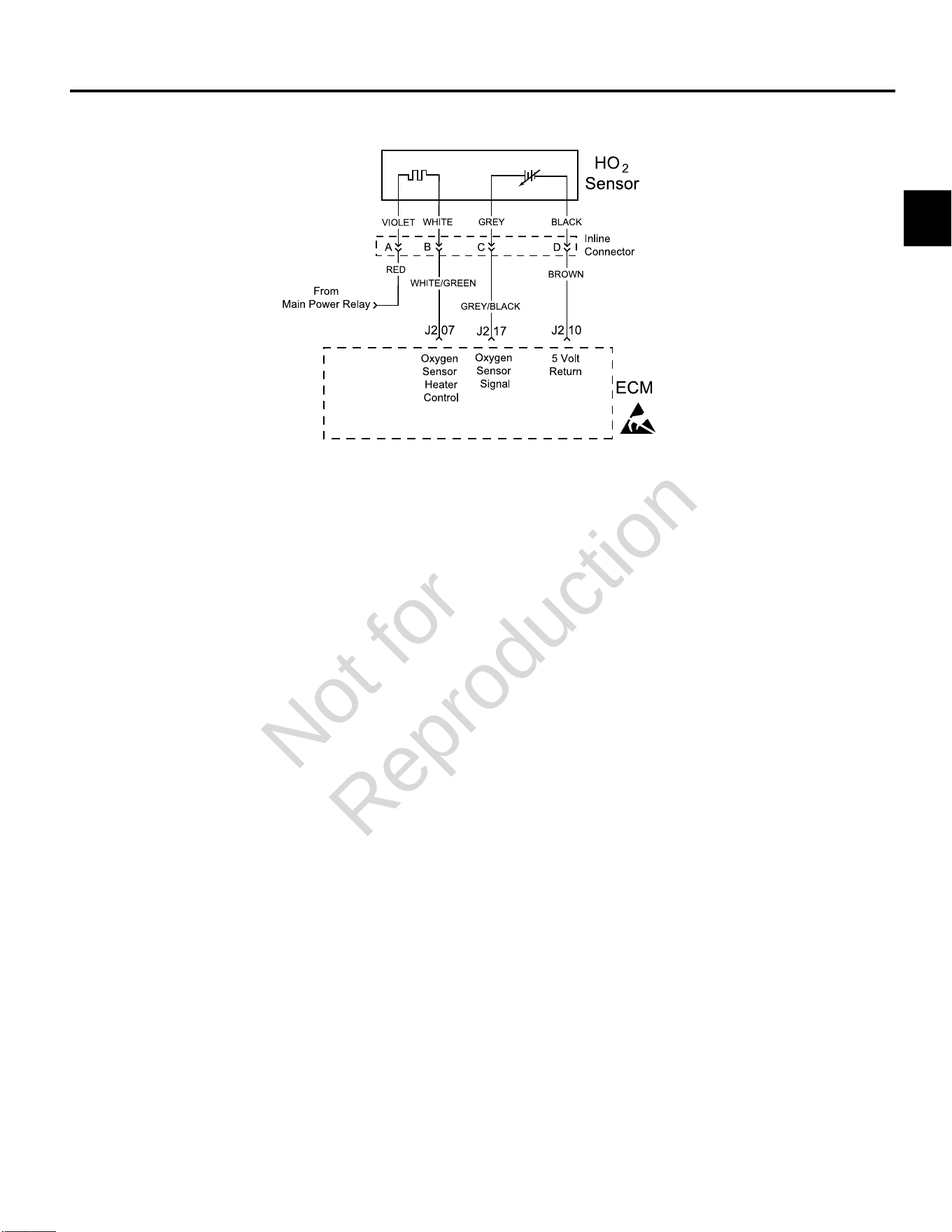
DTC P0031/P0032 OXYGEN SENSOR (HO2) HEATER
Circuit Description
The HO
2
sensor voltage varies from about 1.0 volt if the
exhaust is rich down to about 0.1 volt if the exhaust is
lean.
The sensor behaves like an open circuit and produces
no voltage when the exhaust temperature is below 600°F
(360°C). An open sensor circuit or cold sensor causes an
open loop operation.
The sensor heater provides for faster sensor warm-up.
This allows the sensor to become active in a shorter
period of time and remain active during a long extended
idle.
An active DTC P0031 indicates that the sensor has
developed an open circuit and is operating in Open Loop
mode. DTC P0032 indicates circuit resistance is low and
voltage being returned to the ECM is too high.
Diagnostic Aids
Check for the following conditions:
Poor harness connection. Inspect harness connectors
for backed out terminals, improper mating, broken locks,
improperly formed or damaged terminals, and poor
terminal to wire connection.
Always clear DTCs after performing repairs.
Not for
Reproduction
2
18
DTC P0031 Signal Voltage Low (Non-Scan Diagnostics)
Step Action Yes No
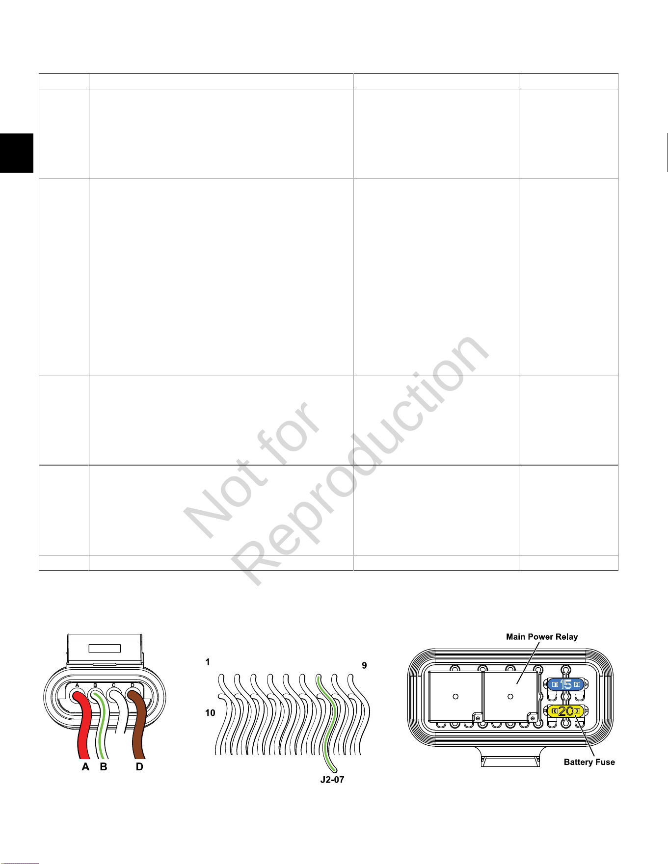
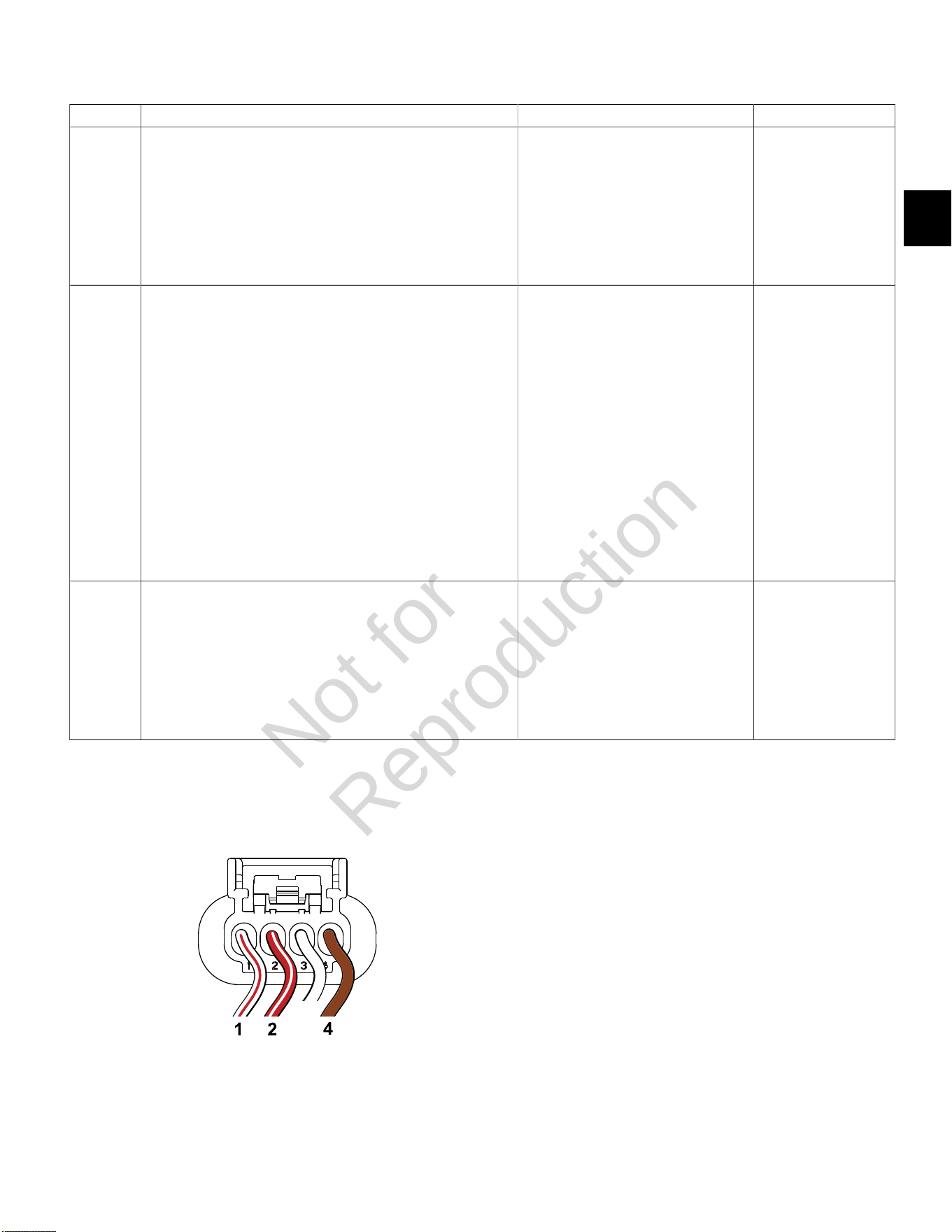
1 1. Disconnect and reconnect O
2
sensor and ECM J2 (Black)
connectors.
2. Turn Ignition ON, Engine OFF. Clear codes.
3. Turn Ignition OFF, and then back ON.
4. Does DTC return?
Go to step 2. Problem corrected.
2 1. Turn Ignition OFF.
2. Back probe (using fused patch cord) terminal A (Red wire) on
engine side of O
2
sensor connector.
3. Connect terminal A back probe to red meter test lead on DVOM.
4. Back probe terminal D (Brown wire) on engine side of O2 sensor
connector.
5. Connect terminal D back probe to black meter test lead on
DVOM.
6. Set DVOM to read volts DC.
7. Turn Ignition ON, Engine Off.
8. Does DVOM read 12.2-13.5 volts DC?
Go to step 3. Perform visual and
continuity check
of Main Power
Relay and 20 amp
Battery fuse (Yellow).
Either there is no power
from fuse block or not
getting ground thru 5
volt return circuit.
3 1. Turn Ignition OFF.
2. Remove probe from terminal A, and back probe terminal B
(White/Green wire) on engine side of O
2
sensor connector.
3. Turn Ignition ON, Engine OFF.
4. Does DVOM read 12.2-13.5 volts DC?
Go to step 4. Replace O
2
sensor.
4 1. Turn Ignition OFF.
2. Remove probe from terminal B, and back probe ECM connector
terminal J2-07 (White/Green wire).
3. Turn Ignition ON, Engine OFF.
4. Does DVOM read 12.2-13.5 volts DC?
Both EFI wire harness
and O
2
sensor are good.
Go to step 5.
5 Are both O
2
sensor and ECM J2 connectors fully mated? Repair or replace EFI wire harness. Connect connectors.
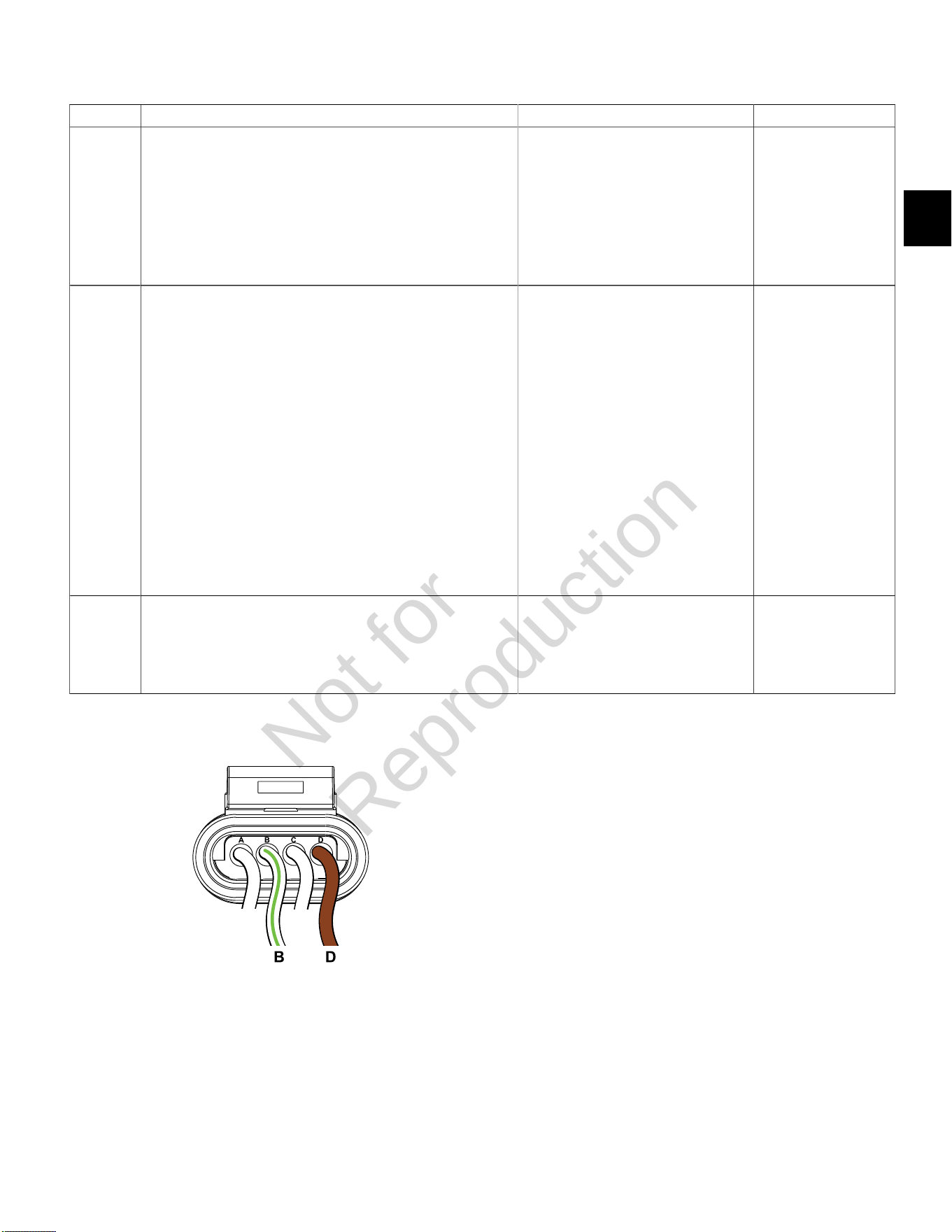
O
2
Sensor Connector ECM J2 (Black) Connector Fuse/Relay Block
Not for
Reproduction
2
19
DTC P0032 Signal Voltage High (Non-Scan Diagnostics)
Step Action Yes No
1 1. Disconnect and reconnect O
2
sensor and ECM J2 (Black)
connectors.
2. Turn Ignition ON, Engine OFF.
3. Clear codes.
4. Turn Ignition OFF, and then back ON.
5. Does DTC return?
Go to step 2. Problem corrected.
2 1. Turn Ignition OFF.
2. Back probe (using fused patch cord) terminal B (White/Green
wire) on engine side of O
2
sensor connector.
3. Connect terminal B back probe to red meter test lead on DVOM.
4. Back probe terminal D (Brown wire) on engine side of O
2
sensor
connector.
5. Connect terminal D back probe to black meter test lead on
DVOM.
6. Set DVOM to read volts DC.
7. Turn Ignition ON, Engine Off.
8. Observe voltage on DVOM.
9. Is reading 12.2-13.5 volts DC?
Go to step 3. Ensure probe
connectivity.
3 1. Start and run engine.
2. Observe voltage on DVOM.
3. Within 15 seconds, does voltage reading drop to less than 100
millivolts?
O
2
sensor OK.
Clear codes and retest.
Replace O
2
sensor.
O
2
Sensor Connector
Not for
Reproduction
2
20
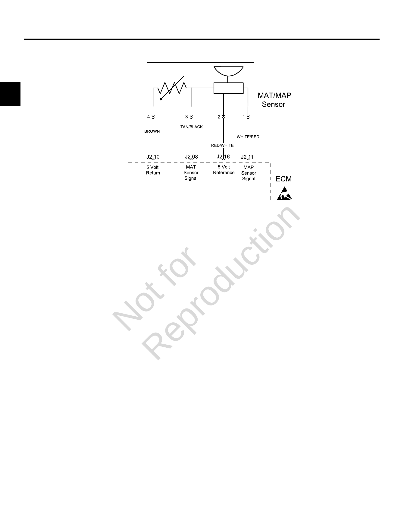
DTC P0107/P0108 MANIFOLD ABSOLUTE PRESSURE (MAP) SENSOR
Circuit Description
The MAP sensor responds to changes in manifold
pressure (vacuum). The ECM receives this information as
a signal voltage that varies between about 0.5 volts at idle
to 4.5 volts at Wide Open Throttle (WOT).
If the MAP sensor fails, the ECM substitutes a default
MAP value.
The MAP sensor voltage of 5 volts is delivered to the
MAP sensor through ECM terminal J2-16. The MAP
sensor sends a voltage signal back to the ECM on
terminal J2-11 according to the manifold pressure value
on the terminal.
Diagnostic Aids
Check for the following conditions:
1. Poor ECM connection. Inspect wire harness
connectors for backed out terminals, improper
mating, broken locks, improperly formed or damaged
terminals, and poor terminal to wire connection.
2. Damaged wire harness and/or connectors. If harness
appears to be OK, shake or wiggle wire harness
and/or connector with DVOM or Diagnostic Tool
connected. Radical voltage changes or a change in
the MAP sensor display can indicate the location of
the fault condition.
Always clear DTCs after performing repairs.
Not for
Reproduction
2
21
DTC P0107 Signal Voltage Low or Open (Scan Diagnostics)
Step Action Yes No
1 1. Select theDashboardicon in the left sidebar and then
theTroubleshootingtab.
2. Observe the MAP Voltage display with or without the engine
running.
3. Is reading 0.5-4.5 volts DC?
MAP sensor circuit OK. Go to step 2.
2 Is reading below 0.5 volts DC? Go to DTC P0107 Non-Scan Diagnostics. -
Not for
Reproduction
2
22
DTC P0107 Signal Voltage Low or Open (Non-Scan Diagnostics)
Step Action Yes No
1 1. Disconnect and reconnect MAP sensor and ECM J2 (Black)
connectors.
2. Turn Ignition ON, Engine OFF.
3. Clear codes.
4. Turn Ignition OFF, and then back ON.
5. Does DTC return?
Go to step 2. Problem corrected.
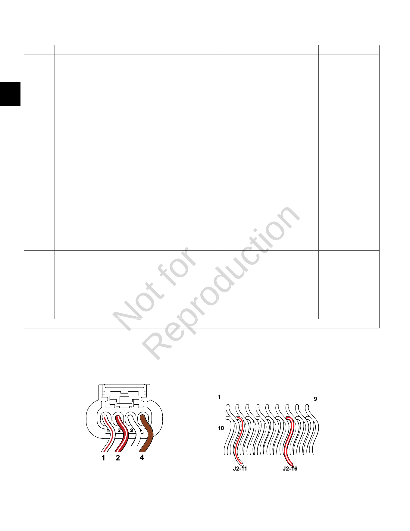
2 1. Turn Ignition OFF.
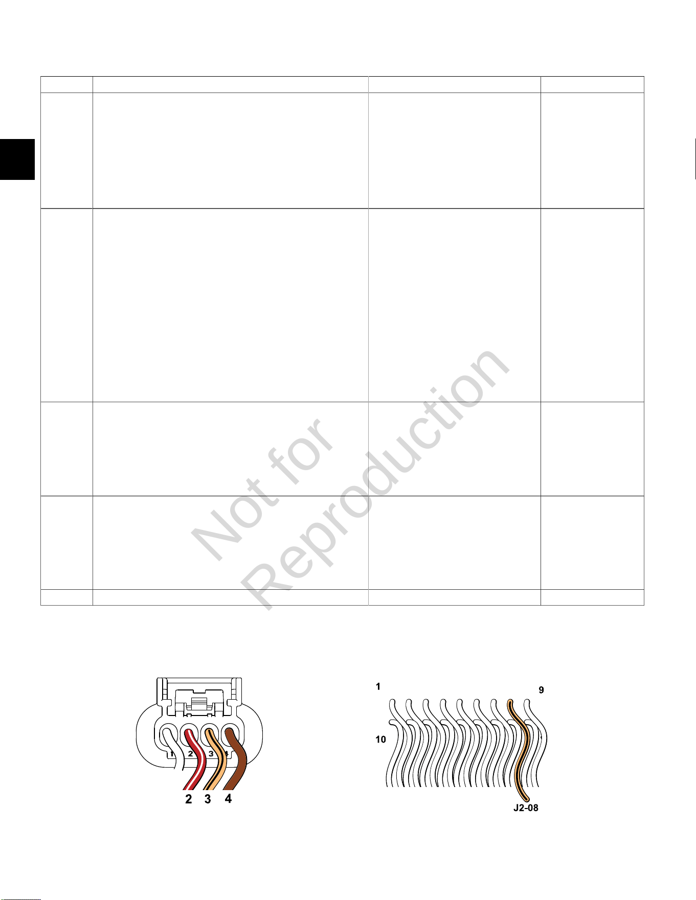
2. Back probe terminal 2 (Red/White wire) of MAP sensor
connector.
3. Connect terminal 2 back probe to red meter test lead on DVOM.
4. Back probe terminal 4 (Brown wire) of MAP sensor connector.
5. Connect terminal 4 back probe to black meter test lead on
DVOM.
6. Set DVOM to read volts DC.
7. Turn Ignition ON, Engine OFF.
8. Observe voltage on DVOM.
9. Is reading 4.6-5.0 volts DC?
Go to step 3. Go to step 3.
3 1. Turn Ignition OFF.
2. Remove probe from terminal 2, and back probe ECM connector
terminal J2-16 (Red/White wire).
3. Turn Ignition ON, Engine OFF.
4. Observe voltage on DVOM.
5. Is reading 4.6-5.0 volts DC?
Go to step 6. Go to step 4.
Continued...
MAP Sensor Connector ECM J2 (Black) Connector
Not for
Reproduction

2
23
Step Action Yes No
4 1. Turn Ignition OFF.
2. Remove probe from terminal J2-16, and back probe terminal 1
(White/Red wire) of MAP sensor connector.
3. Turn Ignition ON, Engine OFF.
4. Observe voltage on DVOM.
5. Is reading 3.7-4.2 volts DC?
MAP sensor OK. Go to step 5.
5 1. Turn Ignition OFF.
2. Remove probe from terminal 1, and back probe ECM connector
terminal J2-11 (White/Red wire).
3. Turn Ignition ON, Engine OFF.
4. Observe voltage on DVOM.
5. Is reading 3.7-4.2 volts DC?
EFI wire harness OK.
Replace MAP sensor.
Go to step 6.
6 1. Not getting ground thru 5 volt return circuit.
2. Are both MAP sensor and ECM J2 connectors fully mated?
Repair or replace EFI wire harness. Connect connectors.
Not for
Reproduction
2
24
DTC P0108 Signal Voltage High (Scan Diagnostics)
Step Action Yes No
1 1. Select theDashboardicon in the left sidebar and then
theTroubleshootingtab.
2. Observe the MAP Voltage display with or without the engine
running.
3. Is reading 0.5-4.5 volts DC?
MAP sensor circuit OK. Go to step 2.
2 Is reading above 4.5 volts DC? Go to DTC P0108 Non-Scan Diagnostics. -
Not for
Reproduction
2
25
DTC P0108 Signal Voltage High (Non-Scan Diagnostics)
Step Action Yes No
1 1. Disconnect and reconnect MAP sensor and ECM J2 (Black)
connectors.
2. Turn Ignition ON, Engine OFF.
3. Clear codes.
4. Turn Ignition OFF, and then back ON.
5. Does DTC return?
Go to step 2. Problem corrected.
2 1. Turn Ignition OFF.
2. Back probe terminal 2 (Red/White wire) of MAP sensor
connector.
3. Connect terminal 2 back probe to red meter test lead on DVOM.
4. Back probe terminal 4 (Brown wire) of MAP sensor connector.
5. Connect terminal 4 back probe to black meter test lead on
DVOM.
6. Set DVOM to read volts DC.
7. Turn Ignition ON, Engine OFF.
8. Observe voltage on DVOM.
9. Is reading 4.7-5.0 volts DC?
Go to step 3. -
3 1. Turn Ignition OFF.
2. Remove probe from terminal 2, and back probe terminal 1
(White/Red wire) of MAP sensor connector.
3. Turn Ignition ON, Engine OFF.
4. Observe voltage on DVOM.
5. Is reading 0.5-4.5 volts DC?
EFI wire harness OK. Reading is above
4.5 volts DC.
Replace MAP sensor.
MAP Sensor Connector
Not for
Reproduction

2
26
DTC P0112/P0113 MANIFOLD AIR TEMPERATURE (MAT) SENSOR
Circuit Description
The MAT sensor uses a thermistor to control signal
voltage to the ECM. The ECM applies 5 volts on the
sensor circuit. Sensor resistance changes as ambient
temperature changes, which in turn affects the voltage
return to the ECM.
Diagnostic Aids
Check for the following conditions:
1. Poor ECM connection.
2. Inspect wire harness connectors for backed out
terminals, improper mating, broken locks, improperly
formed or damaged terminals, and poor terminal to
wire connection.
3. Damaged wire harness and/or connectors. If harness
appears to be OK, shake or wiggle wire harness
and/or connector with DVOM or Diagnostic Tool
connected. Radical voltage changes or a change in
the MAT sensor display can indicate the location of
the fault condition.
Always clear DTCs after performing repairs.
Not for
Reproduction

2
27
DTC P0112 Signal Voltage Low (Scan Diagnostics)
Step Action Yes No
1 1. Select theDashboardicon in the left sidebar and then
theTroubleshootingtab.
2. Observe the IAT Voltage display with or without the engine
running.
3. Is reading 0.5-4.5 volts DC?
MAT sensor circuit OK. Go to step 2.
2 Is reading below 0.5 volts DC? Go to DTC P0112 Non-
Scan Diagnostics.
-
Not for
Reproduction
2
28
DTC P0112 Signal Voltage Low (Non-Scan Diagnostics)
Step Action Yes No
1 1. Disconnect and reconnect MAT sensor and ECM J2 (Black)
connectors.
2. Turn Ignition ON, Engine OFF.
3. Clear codes.
4. Turn Ignition OFF, and then back ON.
5. Does DTC return?
Go to step 2. Problem corrected.
2 1. Turn Ignition OFF.
2. Back probe terminal 2 (Red/White wire) of MAT sensor
connector.
3. Connect terminal 2 back probe to red meter test lead on DVOM.
4. Back probe terminal 4 (Brown wire) of MAT sensor connector.
5. Connect terminal 4 back probe to black meter test lead on
DVOM.
6. Set DVOM to read volts DC.
7. Turn Ignition ON, Engine OFF.
8. Does DVOM read 4.7-5.0 volts DC?
MAT sensor OK. Go to step 3.
3 1. Turn Ignition OFF.
2. Remove probe from terminal 2, and back probe terminal 3 (Tan/
Black wire) of MAT sensor connector.
3. Turn Ignition ON, Engine OFF.
4. Does DVOM read 0.5-4.5 volts DC?
MAT sensor OK. Reading is below
0.5 volts DC.
Replace MAT sensor.
4 1. Turn Ignition OFF.
2. Remove probe from terminal 3, and back probe ECM connector
terminal J2-08 (Tan/Black wire).
3. Turn Ignition ON, Engine OFF.
4. Does DVOM read 0.5-4.5 volts DC?
MAT sensor circuit OK. Go to step 5.
5 Are both MAT sensor and ECM J2 connectors fully mated? Repair or replace EFI wire harness. Connect connectors.
MAT Sensor Connector ECM J2 (Black) Connector
Not for
Reproduction
2
29
DTC P0113 Signal Voltage High or Open (Scan Diagnostics)
Step Action Yes No
1 1. Select theDashboardicon in the left sidebar and then
theTroubleshootingtab.
2. Observe the IAT Voltage display with or without the engine
running.
3. Is reading 0.5-4.5 volts DC?
MAT sensor circuit OK. Go to step 2.
2 Is reading above 4.5 volts DC? Go to DTC P0113 Non-
Scan Diagnostics.
-
Not for
Reproduction
2
30
DTC P0113 Signal Voltage High or Open (Non-Scan Diagnostics)
Step Action Yes No
1 1. Disconnect and reconnect MAT sensor and ECM J2 (Black)
connectors.
2. Turn Ignition ON, Engine OFF.
3. Clear codes.
4. Turn Ignition OFF, and then back ON.
5. Does DTC return?
Go to step 2. Problem corrected.
2 1. Turn Ignition OFF.
2. Back probe terminal 2 (Red/White wire) of MAT sensor
connector.
3. Connect terminal 2 back probe to red meter test lead on DVOM.
4. Back probe terminal 4 (Brown wire) of MAT sensor connector.
5. Connect terminal 4 back probe to black meter test lead on
DVOM.
6. Set DVOM to read volts DC.
7. Turn Ignition ON, Engine OFF.
8. Does DVOM read 4.7-5.0 volts DC?
MAT sensor OK. Go to step 3.
3 1. Turn Ignition OFF.
2. Remove probe from terminal 2, and back probe terminal 3 (Tan/
Black wire) of MAT sensor connector.
3. Turn Ignition ON, Engine OFF.
4. Does DVOM read 0.5-4.5 volts DC?
MAT sensor OK. Reading is above
4.5 volts DC.
Replace MAT sensor.
MAT Sensor Connector
Not for
Reproduction
2
31
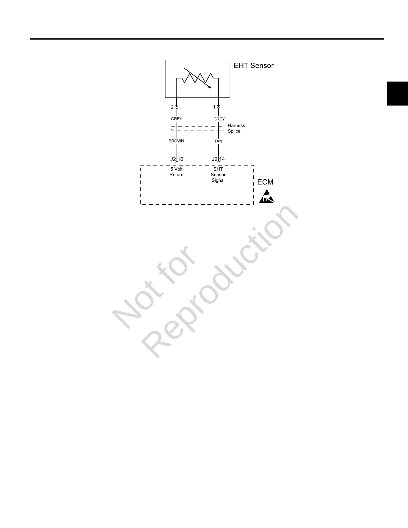
DTC P0117/P0118 ENGINE HEAD TEMPERATURE (EHT) SENSOR
Circuit Description
The EHT sensor uses a thermistor to control signal
voltage to the ECM. The ECM applies 5 volts on the
sensor circuit. Sensor resistance changes as ambient
temperature changes, which in turn affects the voltage
return to the ECM.
Diagnostic Aids
Check for the following conditions:
1. Poor ECM connection.
2. Inspect wire harness connectors for backed out
terminals, improper mating, broken locks, improperly
formed or damaged terminals, and poor terminal to
wire connection.
3. Damaged wire harness and/or connectors. If harness
appears to be OK, shake or wiggle wire harness
and/or connector with DVOM or Diagnostic Tool
connected. Radical voltage changes or a change in
the EHT sensor display can indicate the location of
the fault condition.
Always clear DTCs after performing repairs.
Not for
Reproduction
2
32
DTC P0117 Signal Voltage Low (Scan Diagnostics)
Step Action Yes No
1 1. Select theDashboardicon in the left sidebar and then
theTroubleshootingtab.
2. Observe the EHT Voltage display with or without the engine
running.
3. Is reading 0.5-4.5 volts DC?
EHT sensor circuit OK. Go to step 2.
2 Is reading below 0.5 volts DC? Go to DTC P0117 Non-
Scan Diagnostics.
-
Not for
Reproduction
2
33
DTC P0117 Signal Voltage Low (Non-Scan Diagnostics)
Step Action Yes No
1 1. Disconnect and reconnect ECM J2 (Black) connector.
2. Turn Ignition ON, Engine OFF.
3. Clear codes.
4. Turn Ignition OFF, and then back ON.
5. Does DTC return?
Go to step 2. Problem corrected.
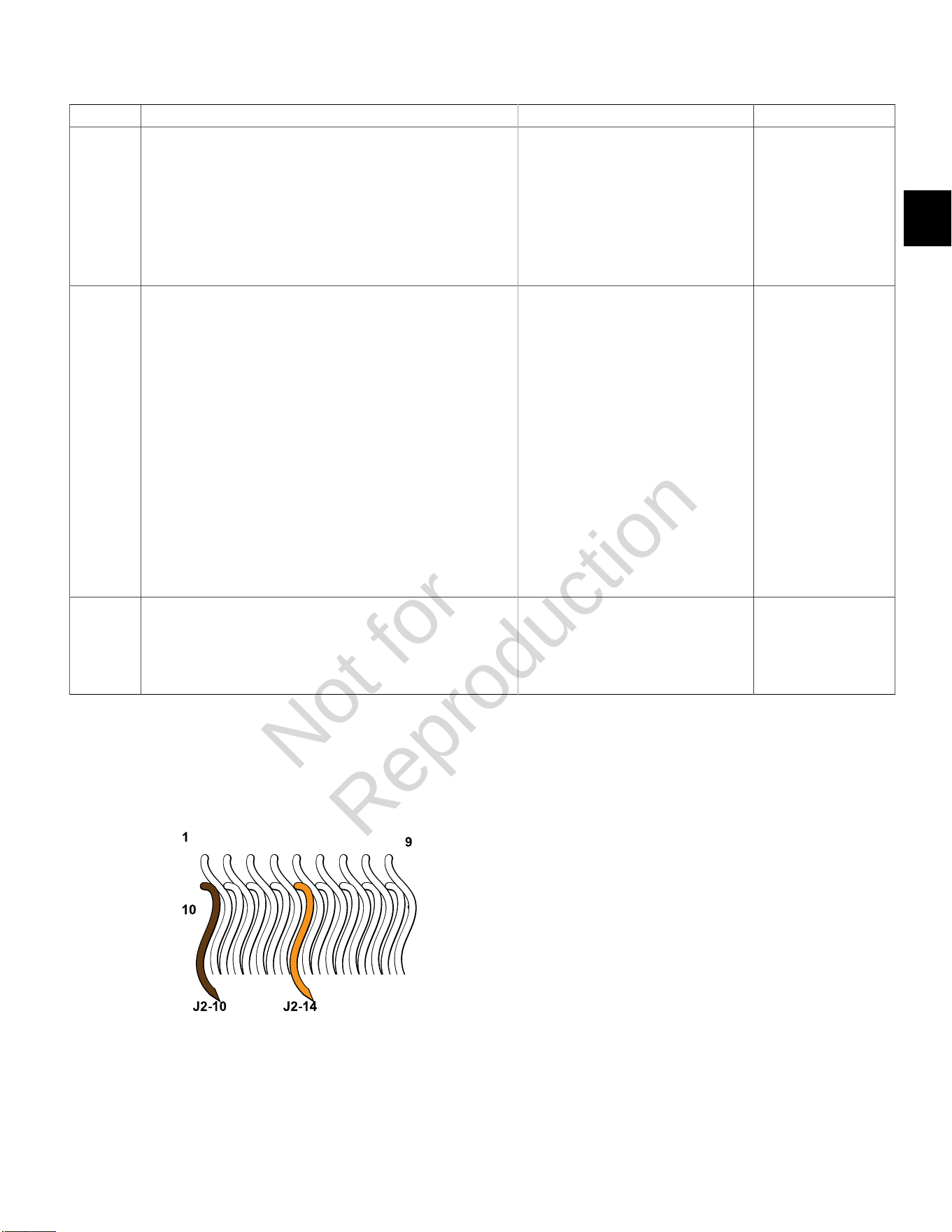
2 1. Turn Ignition OFF.
2. Back probe terminal J2-14 (Tan wire) of ECM connector.
3. Connect terminal J2-14 back probe to red meter test lead on
DVOM.
4. Back probe terminal J2-10 (Brown wire) of ECM connector.
5. Connect terminal J2-10 back probe to black meter test lead on
DVOM.
6. Set DVOM to read volts DC.
7. Turn Ignition ON, Engine OFF.
8. Observe voltage on DVOM.
9. Is reading 0.5-4.5 volts DC?
EHT sensor OK. Go to step 3.
3 1. Reading is below 0.5 volts DC.
2. Is ECM J2 connector fully mated?
EHT sensor is bad.
Replace EFI wire harness.
NOTE:EHT sensor is an integral part
of the EFI wire harness and is not sold
separately.
Connect connector.
ECM J2 (Black) Connector
Not for
Reproduction

2
34
DTC P0118 Signal Voltage High or Open (Scan Diagnostics)
Step Action Yes No
1 1. Select theDashboardicon in the left sidebar and then
theTroubleshootingtab.
2. Observe the EHT Voltage display with or without the engine
running.
3. Is reading 0.5-4.5 volts DC?
EHT sensor circuit OK. Go to step 2.
2 Is reading above 4.5 volts DC? Go to DTC P0118 Non-
Scan Diagnostics.
-
Not for
Reproduction

2
35
DTC P0118 Signal Voltage High or Open (Non-Scan Diagnostics)
Step Action Yes No
1 1. Disconnect and reconnect ECM J2 (Black) connector.
2. Turn Ignition ON, Engine OFF.
3. Clear codes.
4. Turn Ignition OFF, and then back ON.
5. Does DTC return?
Go to step 2. Problem corrected.
2 1. Turn Ignition OFF.
2. Back probe terminal J2-14 (Tan wire) of ECM connector.
3. Connect terminal J2-14 back probe to red meter test lead on
DVOM.
4. Back probe terminal J2-10 (Brown wire) of ECM connector.
5. Connect terminal J2-10 back probe to black meter test lead on
DVOM.
6. Set DVOM to read volts DC.
7. Turn Ignition ON, Engine OFF.
8. Observe voltage on DVOM.
9. Is reading 0.5-4.5 volts DC?
EHT sensor OK. Reading is above
4.5 volts DC. EHT
sensor is bad.
Replace EFI wire
harness.
NOTE:EHT sensor is
an integral part of the
EFI wire harness and is
not sold separately.
ECM J2 (Black) Connector
Not for
Reproduction
2
36
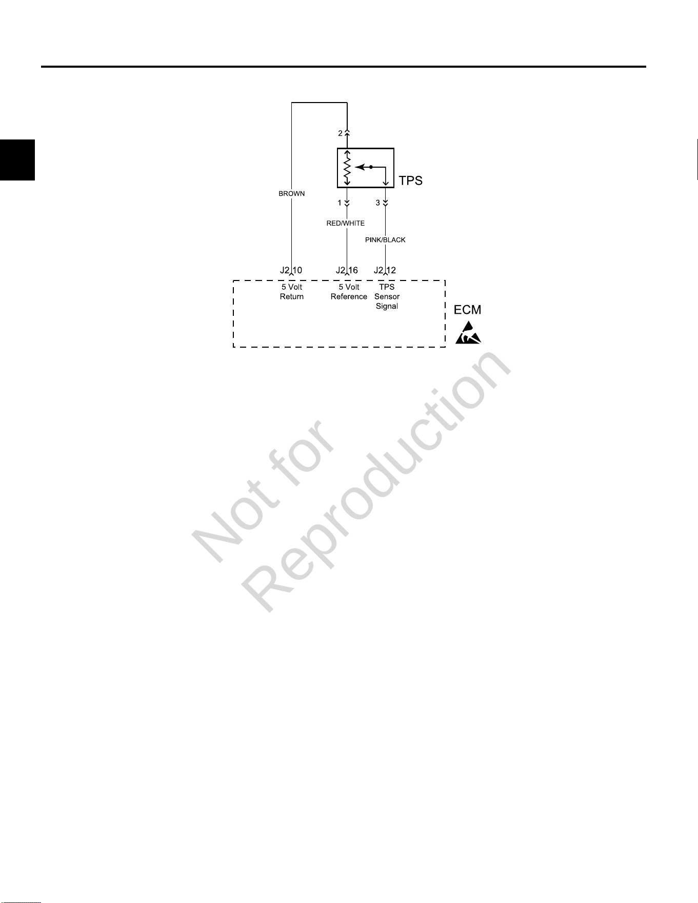
DTC P0122/P0123 THROTTLE POSITION SENSOR (TPS)
Circuit Description
The TPS is a potentiometer connected to the throttle shaft
on the throttle body. The ECM calculates throttle position
by monitoring voltage on the signal circuit. As the throttle
angle changes, the TPS signal also changes. At a closed
throttle position, the voltage output of the TPS is low, but
as the throttle opens, the voltage output increases.
Diagnostic Aids
Check for the following conditions:
1. Poor ECM connection. Inspect wire harness
connectors for backed out terminals, improper
mating, broken locks, improperly formed or damaged
terminals, and poor terminal to wire connection.
2. Damaged wire harness and/or connectors. If harness
appears to be OK, shake or wiggle wire harness and/
or connector with DVOM or ETA connected. Radical
voltage changes or a change in the TPS display can
indicate the location of the fault condition.
Always clear DTCs after performing repairs.
Not for
Reproduction
2
37
DTC P0122 Signal Voltage Low or Open (Scan Diagnostics)
Step Action Yes No
1 1. Select theDashboardicon in the left sidebar and then
theTroubleshootingtab.
2. Observe the TPS Voltage display with or without the engine
running.
3. Is reading 0.5-4.5 volts DC?
TPS circuit OK. Go to step 2.
2 Is reading below 0.5 volts DC? Go to DTC P0122 Non-
Scan Diagnostics.
-
Not for
Reproduction
2
38
DTC P0122 Signal Voltage Low or Open (Non-Scan Diagnostics)
Step Action Yes No
1 1. Disconnect and reconnect TPS and ECM J2 (Black) connectors.
2. Turn Ignition ON, Engine OFF.
3. Clear codes.
4. Turn Ignition OFF, and then back ON.
5. Does DTC return?
Go to step 2. Problem corrected.
2 1. Turn Ignition OFF.
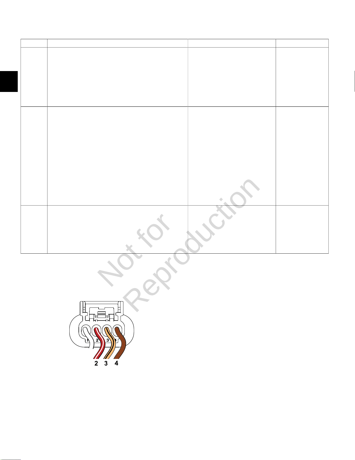
2. Back probe terminal 2 (Brown wire) of TPS connector.
3. Connect terminal 2 back probe to red meter test lead on DVOM.
4. Back probe terminal 1 (Red/White wire) of TPS connector.
5. Connect terminal 1 back probe to black meter test lead on
DVOM.
6. Set DVOM to read volts DC.
7. Turn Ignition ON, Engine OFF.
8. Does DVOM read 4.7-5.0 volts DC?
Go to step 3. Go to step 5.
3 1. Turn Ignition OFF.
2. Remove probe from terminal 2, and back probe terminal 3 (Pink/
Black wire) of TPS connector.
3. Start and run engine at idle speed.
4. Does DVOM read 0.5-0.75 volts DC?
Go to step 4. Reset TPS.
SeeTPS Removal/Installation/
AdjustmentinSECTION 5 - REMOVAL/
INSTALLATION.
4 1. Manually move throttle slowly and steadily toward Wide Open
Throttle position while observing voltage on DVOM.
2. Does voltage steadily increase from 0.73 +/- 0.02 volts?
TPS OK. Reading is below 0.5 volts DC.
Reset or replace TPS.
SeeTPS Removal/Installation/
AdjustmentinSECTION 5 - REMOVAL/
INSTALLATION.
5 1. Not getting ground thru 5 volt return circuit.
2. Are both TPS and ECM J2 (Black) connectors fully mated?
Repair or replace
EFI wire harness.
Connect connectors
TPS Connector
Not for
Reproduction

2
39
DTC P0123 Signal Voltage High (Scan Diagnostics)
Step Action Yes No
1 1. Select theDashboardicon in the left sidebar and then
theTroubleshootingtab.
2. Observe the TPS Voltage display with or without the engine
running.
3. Is reading 0.5-4.5 volts DC?
TPS circuit OK. Go to step 2.
2 Is reading above 4.5 volts DC? Go to DTC P0123 Non-
Scan Diagnostics.
-
Not for
Reproduction

2
40
DTC P0123 Signal Voltage High (Non-Scan Diagnostics)
Step Action Yes No
1 1. Disconnect and reconnect TPS and ECM J2 (Black) connectors.
2. Turn Ignition ON, Engine OFF.
3. Clear codes.
4. Turn Ignition OFF, and then back ON.
5. Does DTC return?
Go to step 2. Problem corrected.
2 1. Turn Ignition OFF.
2. Back probe terminal 2 (Brown wire) of TPS connector.
3. Connect terminal 2 back probe to red meter test lead on DVOM.
4. Back probe terminal 1 (Red/White wire) of TPS connector.
5. Connect terminal 1 back probe to black meter test lead on
DVOM.
6. Set DVOM to read volts DC.
7. Turn Ignition ON, Engine OFF.
8. Does DVOM read 4.7-5.0 volts DC?
Go to step 3. Go to step 6.
3 1. Turn Ignition OFF.
2. Remove probe from terminal 2, and back probe terminal 3 (Pink/
Black wire) of TPS connector.
3. Start and run engine at idle speed.
4. Does DVOM read 0.5-0.75 volts DC?
Go to step 4. Reset TPS.
SeeTPS Removal/Installation/
AdjustmentinSECTION 5 - REMOVAL/
INSTALLATION.
4 1. Manually move throttle slowly and steadily toward Wide Open
Throttle position while observing voltage on DVOM.
2. Does voltage steadily increase from 0.73 +/- 0.02 volts?
Go to step 5. -
5 Does reading exceed 4.5 volts DC at any point? Replace TPS. -
6 1. Not getting ground thru 5 volt return circuit.
2. Are both TPS and ECM J2 (Black) connectors fully mated?
Repair or replace
EFI wire harness.
Connect connectors
TPS Connector
Not for
Reproduction
2
41
DTC P0131/P0132 OXYGEN (HO2) SENSOR
Circuit Description
The HO
2
sensor voltage varies from about 1.0 volt if the
exhaust is rich down to about 0.1 volt if the exhaust is
lean.
The sensor behaves like an open circuit and produces
no voltage when the exhaust temperature is below 600°F
(360°C). An open sensor circuit or cold sensor causes an
open loop operation.
The sensor heater provides for faster sensor warm-up.
This allows the sensor to become active in a shorter
period of time and remain active during a long extended
idle.
An active DTC P0131 indicates that the sensor has
developed an open circuit and is operating in Open Loop
mode. DTC P0132 indicates circuit resistance is low and
voltage being returned to the ECM is too high.
Diagnostic Aids
Check for the following conditions:
Poor harness connection. Inspect harness connectors
for backed out terminals, improper mating, broken locks,
improperly formed or damaged terminals, and poor
terminal to wire connection.
Always clear DTCs after performing repairs.
Not for
Reproduction
2
42
DTC P0131 Signal Voltage Low (Scan Diagnostics)
Step Action Yes No
1 1. Select theDashboardicon in the left sidebar and then
theTroubleshootingtab.
2. Observe the HO
2
SSensor display with or without the engine
running.
NOTE:An HO
2
S Sensor display can also be viewed under
theDealertab.
3. Is reading 600-950 millivolts DC?
HO
2
sensor circuit OK. Go to step 2.
2 Is reading below 600 millivolts DC? Go to DTC P0131 Non-Scan Diagnostics. -
Not for
Reproduction
2
43
DTC P0131 Signal Voltage Low (Non-Scan Diagnostics)
Step Action Yes No
1 1. Disconnect and reconnect HO
2
sensor and ECM J2 (Black)
connectors.
2. Turn Ignition ON, Engine OFF.
3. Clear codes.
4. Turn Ignition OFF, and then back ON.
5. Does DTC return?
Go to step 2. Problem corrected.
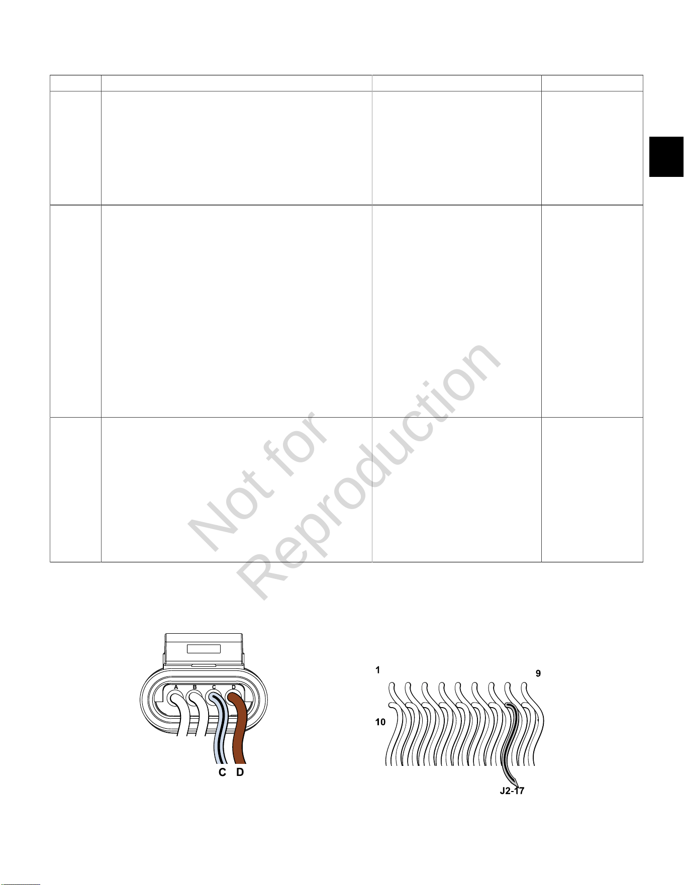
2 1. Turn Ignition OFF.
2. Back probe terminal C (Grey/Black wire) of HO
2
sensor
connector.
3. Connect terminal C back probe to red meter test lead on DVOM.
4. Back probe terminal D (Brown wire) of HO
2
sensor connector.
5. Connect terminal D back probe to black meter test lead on
DVOM.
6. Set DVOM to read volts DC.
7. Start and run engine for at least 2 minutes.
8. With engine running, observe voltage on DVOM.
9. Is reading 600 – 950 millivolts DC?
HO
2
sensor OK. Go to step 3.
3 1. Turn Ignition OFF.
2. Remove probe from terminal C, and back probe ECM connector
terminal J2-17 (Grey/Black wire).
3. Start and run engine.
4. Observe voltage on DVOM.
5. Is reading 600 – 950 millivolts DC?
HO
2
sensor OK. Verify that both
HO
2
sensor and ECM
J2 (Black) connectors
are fully mated.
NOTE:If reading is
below 300 millivolts DC,
inspect exhaust system
for cracks or leaks
between muffler and
cylinder head (gaskets).
If everything is OK,
replace HO
2
sensor.
HO
2
Sensor Connector ECM J2 (Black) Connector
Not for
Reproduction

2
44
DTC P0132 Signal Voltage High (Scan Diagnostics)
Step Action Yes No
1 1. Select theDashboardicon in the left sidebar and then
theTroubleshootingtab.
2. Observe the HO
2
S Sensor display with or without the engine
running.
NOTE:An HO
2
S Sensor display can also be viewed under
theDealertab.
3. Is reading 600-950 millivolts DC?
HO
2
sensor circuit OK. Go to step 2.
2 Is reading above 950 millivolts DC, but below 1014.8 millivolts DC? Go to DTC P0132 Non-Scan Diagnostics. -
Not for
Reproduction
2
45
DTC P0132 Signal Voltage High (Non-Scan Diagnostics)
Step Action Yes No
1 1. Disconnect and reconnect HO
2
sensor and ECM J2 (Black)
connectors.
2. Turn Ignition ON, Engine OFF.
3. Clear codes.
4. Turn Ignition OFF, and then back ON.
5. Does DTC return?
Go to step 2. Problem corrected.
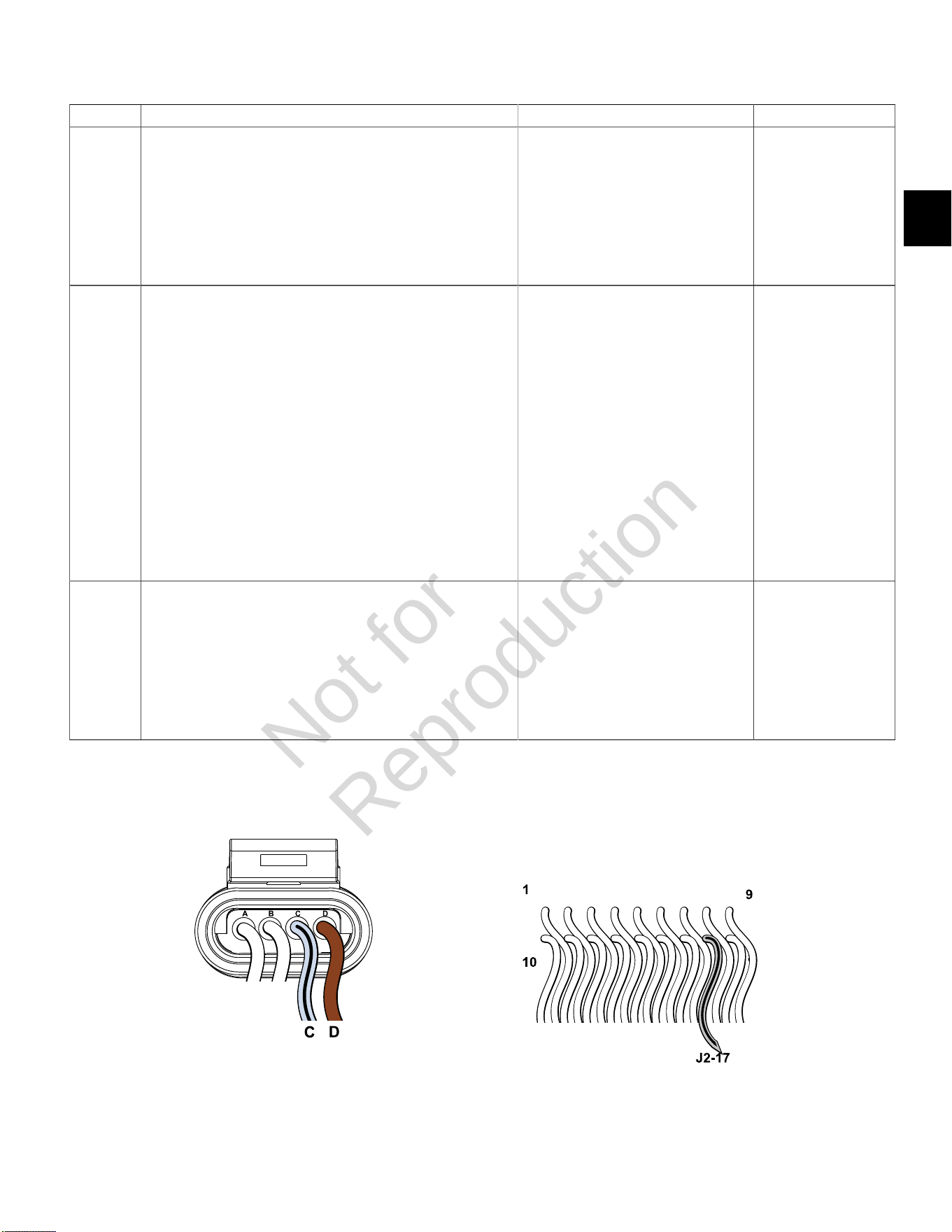
2 1. Turn Ignition OFF.
2. Back probe terminal C (Grey/Black wire) of HO
2
sensor
connector.
3. Connect terminal C back probe to red meter test lead on DVOM.
4. Back probe terminal D (Brown wire) of HO
2
sensor connector.
5. Connect terminal D back probe to black meter test lead on
DVOM.
6. Set DVOM to read volts DC.
7. Start and run engine for at least 2 minutes.
8. With engine running, observe voltage on DVOM.
9. Is reading 600 – 950 millivolts DC?
HO
2
sensor OK. Go to step 3.
3 1. Turn Ignition OFF.
2. Remove probe from terminal C, and back probe ECM connector
terminal J2-17 (Grey/Black wire).
3. Start and run engine.
4. Observe voltage on DVOM.
5. Is reading 600 – 950 millivolts DC?
HO
2
sensor OK. Verify that both
HO
2
sensor and ECM
J2 (Black) connectors
are fully mated.
NOTE:If reading is
above 950 millivolts DC,
replace HO
2
sensor
or identify overly rich
running condition.
HO
2
Sensor Connector ECM J2 (Black) Connector
Not for
Reproduction

2
46
DTC P0174 POWER ENRICHMENT (PE)
Circuit Description
The PE mode is initiated in higher load running
conditions. The ECM uses the MAP and CKP sensor
inputs to know when to go into PE mode. PE fueling
provides for optimal performance and maximum power.
It also prevents against excessive exhaust valve and
engine temperatures.
If DTC P0174 is set, the ECM is detecting an overly lean
condition under heavy load.
Diagnostic Aids
Always clear DTCs after performing repairs.
DTC P0174 Lean Fuel Condition (Non-Scan Diagnostics)
Step Action Yes No
1 1. Check fuel filter and fuel lines for dirt, debris or other restriction.
2. Is a problem found?
Repair. Go to step 2.
2 1. Check fuel pressure. SeeCHECK/RELIEVE FUEL SYSTEM
PRESSUREinSECTION 5 - REMOVAL/INSTALLATION.
2. Is fuel pressure 38-43 psi (262-296 kPa)?
- Go to step 3.
3 1. Verify that fuel filter is not clogged or restricted, and that fuel
pump is operating properly (seeMechanical Diaphragm Fuel
PumporElectric Lift Fuel Pump, Volumetric Test,inSECTION 5 -
REMOVAL/INSTALLATION.
2. Is a problem found?
Repair. Go to step 4.
4 1. Check for vacuum and exhaust leaks.
2. Is a leak found?
Repair. Go to step 5.
5 1. Check for faulty fuel injectors.
2. Are faulty fuel injectors found?
Repair. Go to step 6.
6 1. Replace faulty HO
2
sensor.
2. Is problem corrected?
- Contact engine
manufacturer.
Not for
Reproduction
2
47
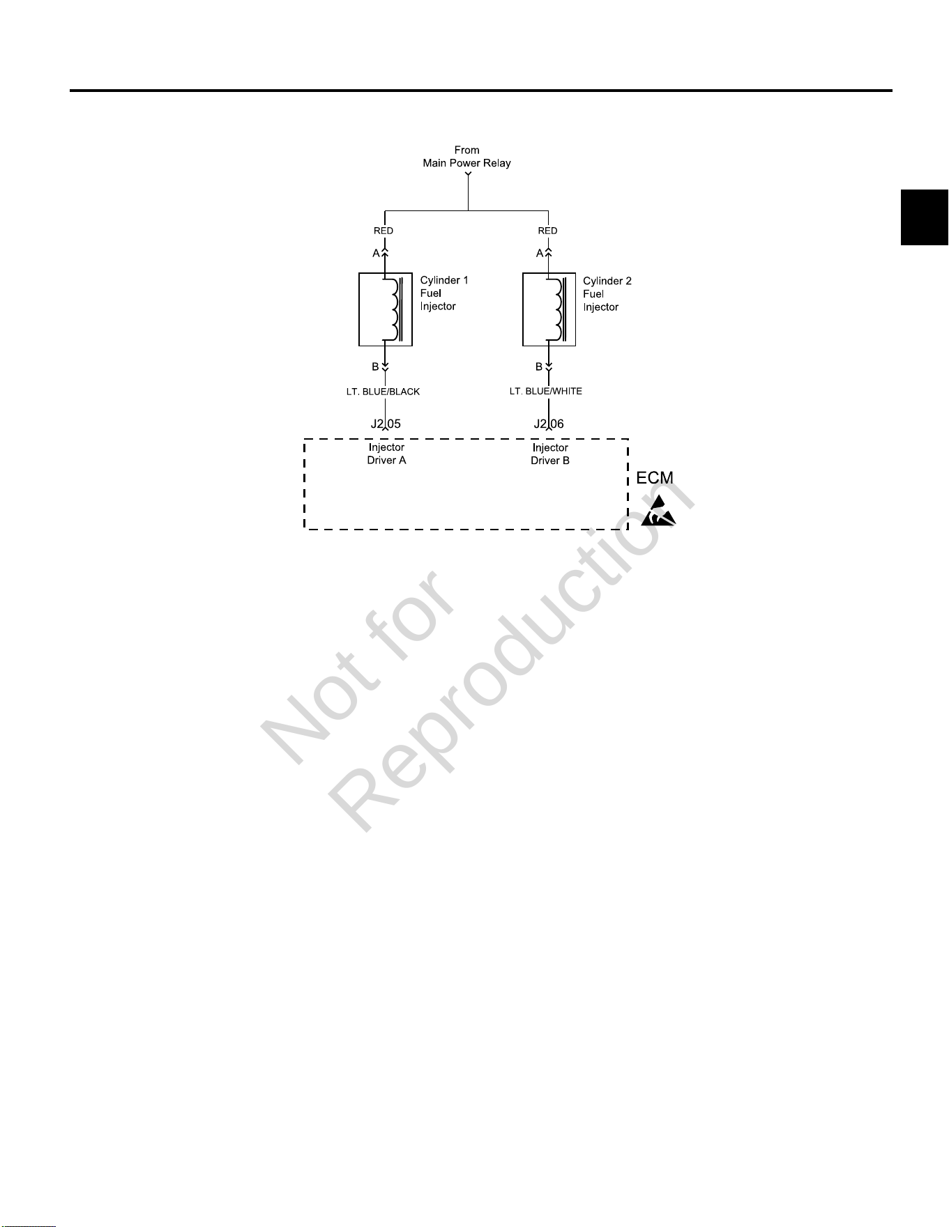
DTC P0201/P0202 CYLINDER 1 OR CYLINDER 2 FUEL INJECTOR
Circuit Description
The ECM controls each fuel injector by grounding the
control circuit via a solid state device called a driver. If the
ECM detects an unacceptable difference in resistance, a
fuel injector control DTC is set.
Although the DTC indicates which fuel injector is faulty,
the technician must determine if the fault is in the ground
circuit or the +12v circuit from the main power relay.
NOTE: If an ignition coil fault code is active, the fuel
injector for the same cylinder is turned off.
Diagnostic Aids
Check for the following conditions:
1. Poor ECM connection.
2. Inspect wire harness connectors for backed out
terminals, improper mating, broken locks, improperly
formed or damaged terminals, and poor terminal to
wire connection.
3. Damaged wire harness and/or connectors. If harness
appears to be OK, shake or wiggle wire harness
and/or connector with DVOM attached. Radical
voltage changes can indicate the location of the fault
condition.
4. Open fuse in fuse block.
Always clear DTCs after performing repairs.
Not for
Reproduction
2
48
DTC P0201 Cylinder 1 Fuel Injector Fault (Non-Scan Diagnostics)
Step Action Yes No
1 1. Disconnect and reconnect cylinder 1 fuel injector and ECM J2 (Black)
connectors.
2. Turn Ignition ON, Engine OFF.
3. Clear codes.
4. Turn Ignition OFF, and then back ON.
5. Does DTC return?
Go to step 2. Problem corrected.
2 1. Turn Ignition OFF.
2. Disconnect fuel injector connector.
3. Install Briggs & Stratton Noid Light (Part No. 19623).
4. Start and run engine.
5. Does Noid Light flash?
Replace fuel injector. Go to step 3.
3 1. Turn Ignition OFF.
2. Remove Noid Light and connect fuel injector connector.
3. Back probe (using fused patch cord) terminal A (Red wire) of fuel injector
connector.
4. Connect terminal A back probe to red meter test lead on DVOM.
5. Connect black meter test lead to a known good ground.
6. Set DVOM to read volts DC.
7. Turn Ignition ON, Engine OFF.
8. Does DVOM read 12.2-13.5 volts DC?
Go to step 4. Reading is below
12.2 volts DC.
Perform visual and
continuity check of
Main Power Relay and
20 amp Battery fuse
(Yellow).
Continued...
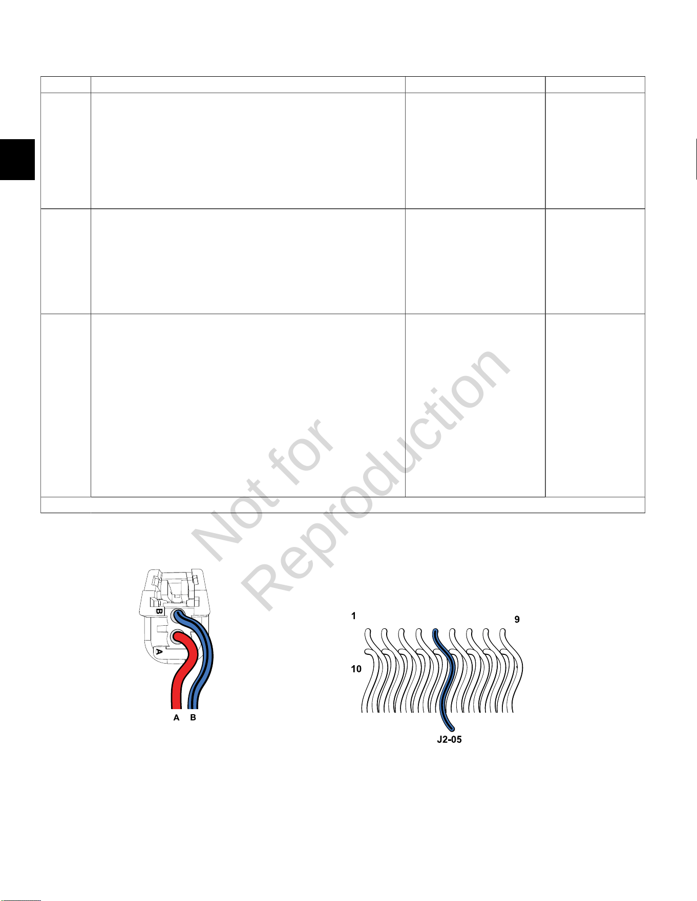
Cylinder 1 Fuel Injector Connector ECM J2 (Black) Connector
Not for
Reproduction

2
49
Step Action Yes No
4 1. Turn Ignition OFF.
2. Disconnect fuel injector connector.
3. Disconnect ECM J2 connector.
4. Back probe terminal B (Lt. Blue/Black wire) of fuel injector connector.
5. Connect terminal B back probe to red meter test lead on DVOM.
6. Back probe terminal J2-05 (Lt. Blue/Black wire) of ECM J2 connector.
7. Connect terminal J2-05 back probe to black meter test lead on DVOM.
8. Set DVOM to read resistance.
9. Does DVOM read less than 0.5 ohms?
Control circuit is OK. Reading is above 0.5
ohms. Check terminals
for corrosion or replace
EFI wire harness.
NOTE:If DTC
still present after
replacement of EFI
wire harness, then
replace ECM due to
failed injector driver.
Not for
Reproduction
2
50
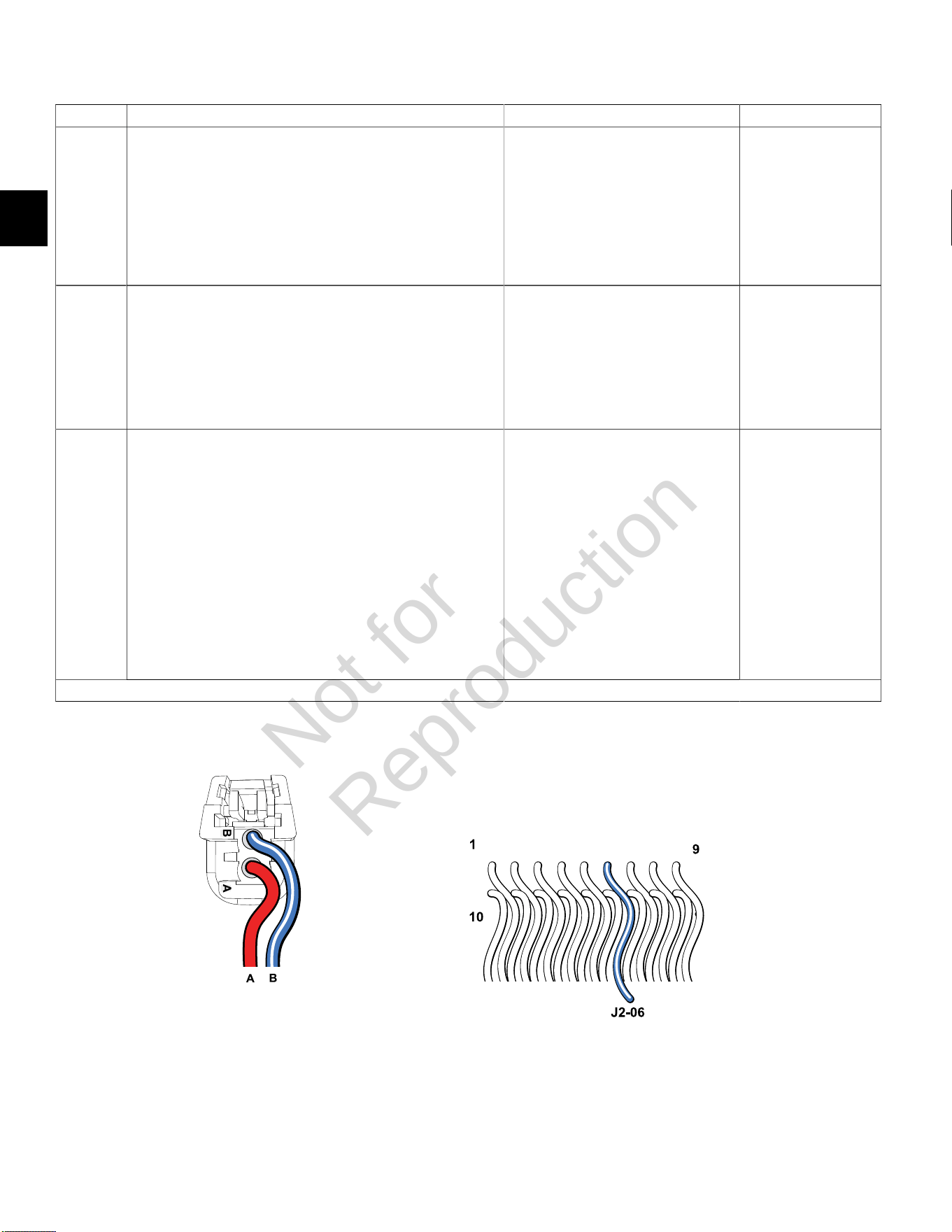
DTC P0202 Cylinder 2 Fuel Injector Fault (Non-Scan Diagnostics)
Step Action Yes No
1 1. Disconnect and reconnect cylinder 2 fuel injector and ECM J2
(Black) connectors.
2. Turn Ignition ON, Engine OFF.
3. Clear codes.
4. Turn Ignition OFF, and then back ON.
5. Does DTC return?
Go to step 2. Problem corrected.
2 1. Turn Ignition OFF.
2. Disconnect fuel injector connector.
3. Install Briggs & Stratton Noid Light (Part No. 19623).
4. Start and run engine.
5. Does Noid Light flash?
Replace fuel injector. Go to step 3.
3 1. Turn Ignition OFF.
2. Remove Noid Light and connect fuel injector connector.
3. Back probe (using fused patch cord) terminal A (Red wire) of
fuel injector connector.
4. Connect terminal A back probe to red meter test lead on DVOM.
5. Connect black meter test lead to a known good ground.
6. Set DVOM to read volts DC.
7. Turn Ignition ON, Engine OFF.
8. Does DVOM read 12.2-13.5 volts DC?
Go to step 4. Reading is below
12.2 volts DC.
Perform visual and
continuity check of
Main Power Relay and
20 amp Battery fuse
(Yellow).
Continued...
Cylinder 2 Fuel Injector Connector ECM J2 (Black) Connector
Not for
Reproduction

2
51
Step Action Yes No
4 1. Turn Ignition OFF.
2. Disconnect fuel injector connector.
3. Disconnect ECM J2 connector.
4. Back probe terminal B (Lt. Blue/White wire) of fuel injector
connector.
5. Connect terminal B back probe to red meter test lead on DVOM.
6. Back probe terminal J2-06 (Lt. Blue/White wire) of ECM J2
connector.
7. Connect terminal J2-06 back probe to black meter test lead on
DVOM.
8. Set DVOM to read resistance.
9. Does DVOM read less than 0.5 ohms?
Control circuit is OK. Reading is above 0.5
ohms. Check terminals
for corrosion or replace
EFI wire harness.
NOTE:If DTC
still present after
replacement of EFI wire
harness, then replace
ECM due to failed
injector driver.
Not for
Reproduction
2
52
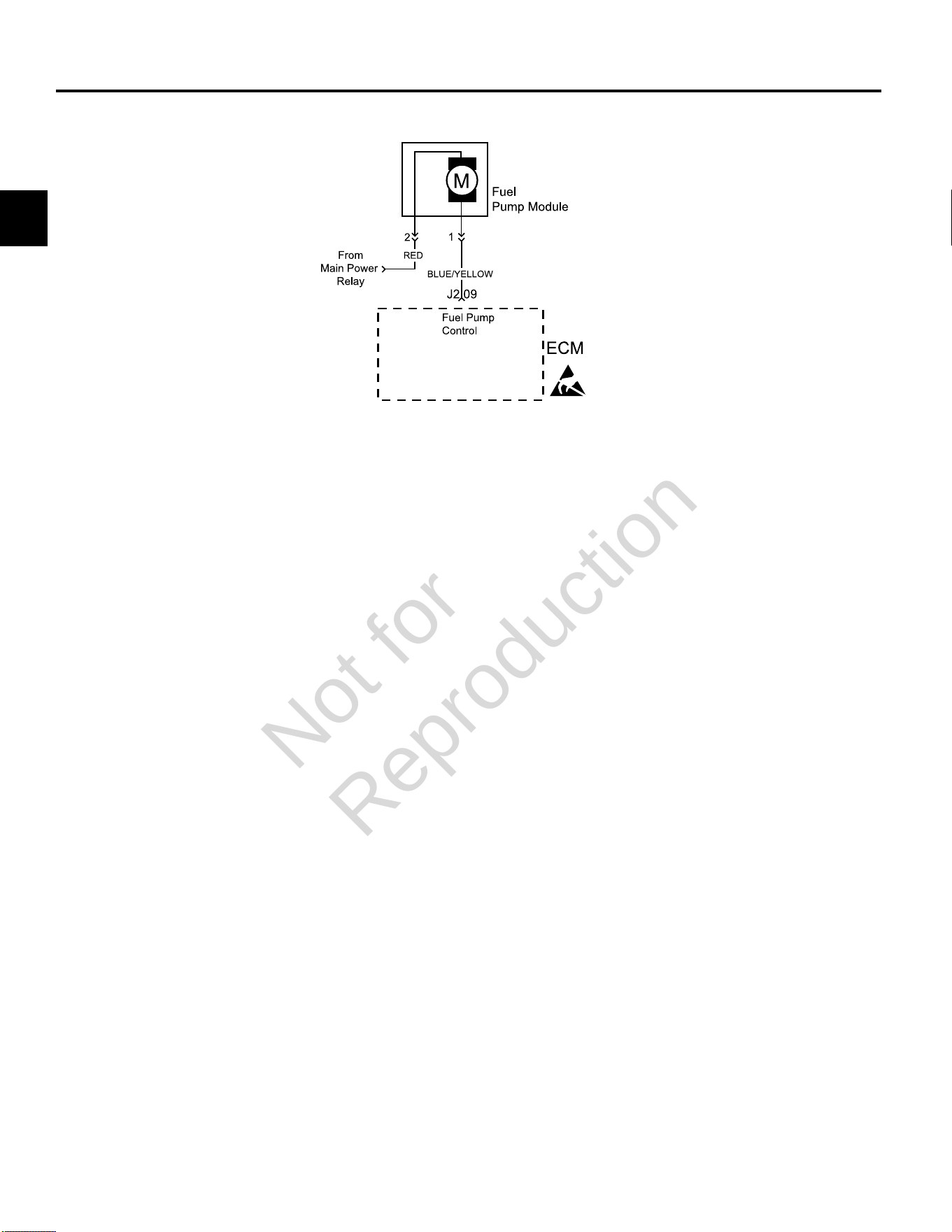
DTC P0230/P0232 FUEL PUMP FAULT
Circuit Description
The fuel pump is controlled by the ECM via the ground
circuit of the fuel pump plug. if resistance is unacceptable
in that circuit the fuel pump DTC is set.
• DTC 230 shows that the signal voltage is low, which
indicates voltage is lost to the pump, high circuit
resistance, or open connection.
• DTC 232 indicates that higher than expected voltage
is seen on the circuit, which means that the fuel pump
is not providing enough resistance or is turning too
slowly.
When the ignition switch is turned ON, the ECM activates
the electric fuel pump module. The fuel pump module
remains ON as long as the ECM receives reference
pulses from the CKP sensor. If there are no reference
pulses, the ECM turns the fuel pump relay OFF after
about 2 seconds. This shuts off the fuel pump. The
fuel pump module delivers fuel to the fuel rail and fuel
injectors.
Diagnostic Aids
The following conditions may have caused the fuel pump
fuse to malfunction:
1. Faulty fuse.
2. Intermittent short in the fuel pump power feed circuit.
3. Fuel pump has an intermittent internal problem.
4. Poor ECM connection.
5. Inspect wire harness connectors for backed out
terminals, improper mating, broken locks, improperly
formed or damaged terminals, and poor terminal to
wire connection.
6. Inspect wire harness and relay for damage.
7. Check fuse block for an open fuse.
Always clear DTCs after performing repairs.
Not for
Reproduction
2
53
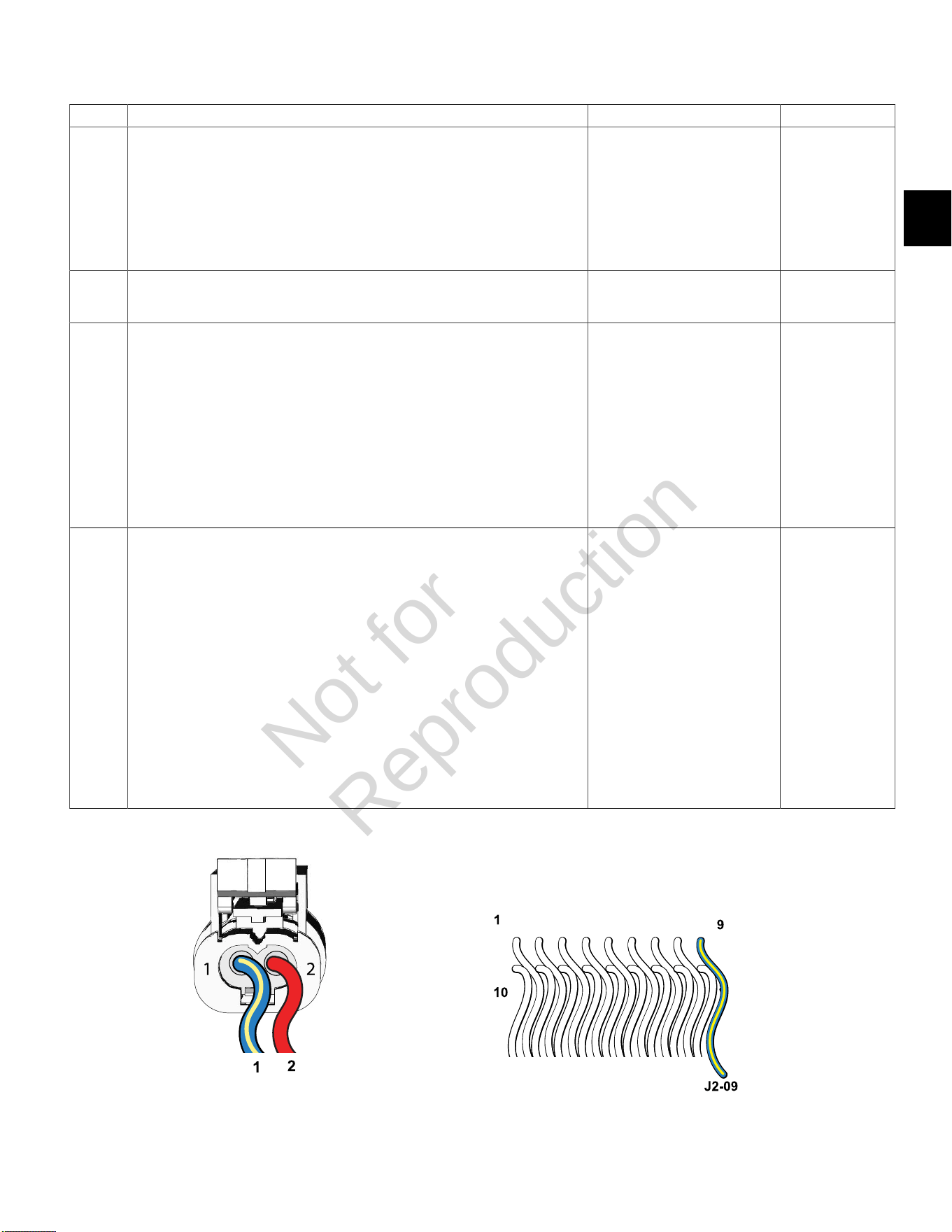
DTC P0230 Signal Voltage Low or Open (Non-Scan Diagnostics)
Step Action Yes No
1 1. Disconnect and reconnect fuel pump module and ECM J2 (Black) connectors.
2. Turn Ignition ON, Engine OFF.
3. Clear codes.
4. Turn Ignition OFF, and then back ON.
5. Does DTC return?
Go to step 2. Problem corrected.
2 1. Turn Ignition OFF, and then back ON.
2. Does fuel pump run for 2 seconds?
Fuel pump module OK. Go to step 3.
3 1. Turn Ignition OFF.
2. Back probe terminal 2 (Red wire) of fuel pump module connector.
3. Connect terminal 2 back probe to red meter test lead on DVOM.
4. Connect black meter test lead on DVOM to a known good ground.
5. Set DVOM to read volts DC.
6. Turn Ignition ON, Engine OFF.
7. Does DVOM read 12.2-13.5 volts DC?
Go to step 4. Perform visual
and continuity
check of Main
Power Relay and
20 amp Battery
fuse (Yellow).
4 1. Turn Ignition OFF.
2. Disconnect fuel pump module connector.
3. Remove probe from terminal 2, and back probe terminal 1 (Blue/Yellow wire) of
fuel pump module connector.
4. Connect terminal 1 back probe to red meter test lead on DVOM.
5. Disconnect ECM J2 connector.
6. Back probe terminal J2-09 (Blue/Yellow wire) of ECM J2 connector.
7. Connect terminal J2-09 back probe to black meter test lead on DVOM.
8. Set DVOM to read resistance.
9. Does DVOM read 0.5 ohm or less?
Replace fuel pump module. Resistance reading
is above 0.5 ohm.
Check terminals
for corrosion or
replace EFI wire
harness.
Fuel Pump Module Connector ECM J2 (Black) Connector
Not for
Reproduction
2
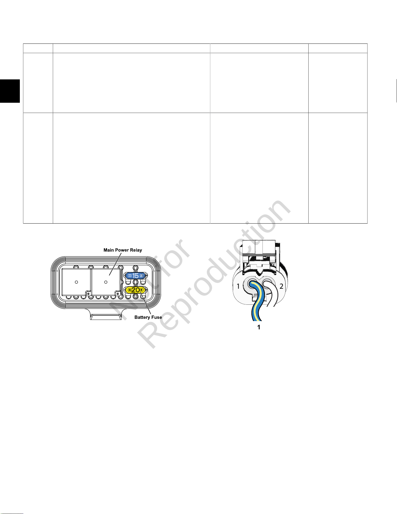
54
DTC P0232 Signal Voltage High (Non-Scan Diagnostics)
Step Action Yes No
1 1. Disconnect and reconnect fuel pump module connector.
2. Turn Ignition ON, Engine OFF.
3. Clear codes.
4. Turn Ignition OFF, and then back ON.
5. Does DTC return?
Go to step 2. Problem corrected.
2 1. Turn Ignition OFF.
2. Back probe terminal 1 (Blue/Yellow wire) of fuel pump module
connector.
3. Connect terminal 1 back probe to red meter test lead on DVOM.
4. Connect black meter test lead on DVOM to a known good
ground..
5. Set DVOM to read volts DC.
6. Attempt to start engine while observing voltage on DVOM.
7. Is reading below 1.0 volts DC?
NOTE:It is OK if engine starts.
System performing OK. Reading is above
1.0 volts DC.
Replace fuel pump
module.
Fuse/Relay Block Fuel Pump Module Connector
Not for
Reproduction
2
55
DTC P0336/P0337 CRANKSHAFT POSITION (CKP) SENSOR
Modes of Operation
The CKP sensor works in conjunction with the 23X
reluctor target wheel on the flywheel. Each tooth on the
reluctor wheel is equally spaced with 1 tooth missing for
the reference sync pulse. As the crankshaft rotates, the
reluctor target wheel interrupts a magnetic field produced
by an internal sensor magnet. The CKP sensor internal
circuitry detects this interruption, and produces an ON/
OFF AC voltage of varying frequency. The frequency
of the CKP sensor output signal is dependent upon
crankshaft speed. The ECM uses each CKP sensor
output signal to determine crankshaft speed and identify
crankshaft position.
With the spark under control of the ECM, the engine will
not run if the CKP sensor signal is lost. The ECM will not
be able to determine which stroke the pistons are on.
Diagnostic Aids
Check for the following conditions:
1. Verify that the CKP sensor is gapped at0.030
inches(0.76 mm) from the target wheel.
2. Poor ECM connection. Inspect harness connectors
for backed out terminals, improper mating, broken
locks, improperly formed or damaged terminals, and
poor terminal to wire connection.
Always clear DTCs after performing repairs.
Not for
Reproduction
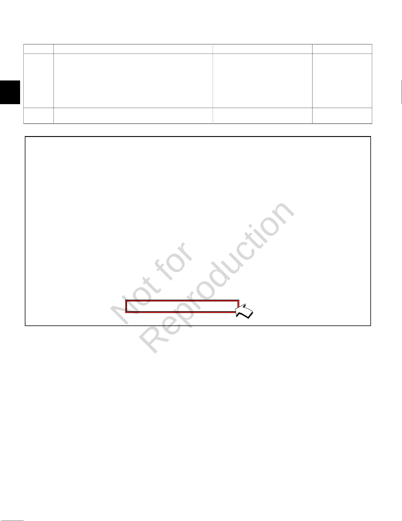
2
56
DTC P0336 Signal Voltage Noisy (Scan Diagnostics)
Step Action Yes No
1 1. Select theDashboardicon in the left sidebar to view
theDealertab.
2. Observe the Flywheel Tooth Error Count display with or without
the engine running.
3. Is reading below 20?
CKP sensor circuit OK. Go to step 2.
2 Is reading 20 or above? Go to DTC P0336 Non-Scan Diagnostics. -
Not for
Reproduction

2
57
DTC P0336 Signal VoltageNoisy (Non-Scan Diagnostics)
Step Action Yes No
1 1. Disconnect and reconnect CKP sensor connector.
2. Turn Ignition ON, Engine OFF.
3. Clear codes.
4. Turn Ignition OFF, and then back ON.
5. Does DTC return?
Go to step 2. Problem corrected.
2 1. Turn Ignition OFF.
2. Check CKP sensor air gap.
3. Is CKP sensor air gap set at 0.030 inches (0.76 mm)?
NOTE:If air gap is too large, engine will likely backfire during
cranking.
Go to step 3. Adjust as necessary.
3 1. Obtain two Briggs & Stratton Spark Testers (Part No. 19368).
2. Install spark testers in line with high tension leads and spark
plugs.
3. Look for spark in tester windows while cranking engine.
4. Is spark observed?
Go to step 4. Repair or replace
spark plugs and/
or high tension
lead/ignition coil.
4 1. Turn Ignition OFF.
2. Check valve lash adjustment.
3. Is valve lash within specification?
Go to step 5. Adjust as necessary.
5 1. Replace CKP sensor.
2. Is problem corrected?
- Repair or replace
EFI wire harness.
Spark Tester (Part No. 19368)
Not for
Reproduction

2
58
DTC P0337 Signal Voltage Absent (Scan Diagnostics)
Step Action Yes No
1 1. Select theDashboardicon in the left sidebar to view
theDealertab.
2. Observe the Engine Speed display while cranking.
NOTE:An Engine Speed display can also be viewed under
theTroubleshootingtab.
3. Is reading above zero?
CKP sensor circuit OK. Go to DTC P0337 Non-
Scan Diagnostics.
Not for
Reproduction

2
59
DTC P0337 Signal VoltageAbsent (Non-Scan Diagnostics)
Step Action Yes No
1 1. Disconnect and reconnect CKP sensor connector.
2. Turn Ignition ON, Engine OFF.
3. Clear codes.
4. Turn Ignition OFF, and then back ON.
5. Does DTC return?
Go to step 2. Problem corrected.
2 1. Turn Ignition OFF.
2. Disconnect cylinder 1 fuel injector connector.
3. Install Briggs & Stratton Noid Light (Part No. 19623).
4. Observe Noid Light while cranking engine.
5. Does Noid Light flash?
Go to step 3. Go to step 3.
3 1. Turn Ignition OFF.
2. Obtain two Briggs & Stratton Spark Testers (Part No. 19368).
3. Install spark testers in line with high tension leads and spark
plugs.
4. Look for spark in tester windows while cranking engine.
5. Is spark observed?
Check CKP sensor connections. Go to step 4.
4 1. Turn Ignition OFF.
2. Replace CKP sensor.
3. Is problem corrected?
- Repair or replace
EFI wire harness.
Noid Light (Part No. 19623) Spark Tester (Part No. 19368)
Not for
Reproduction
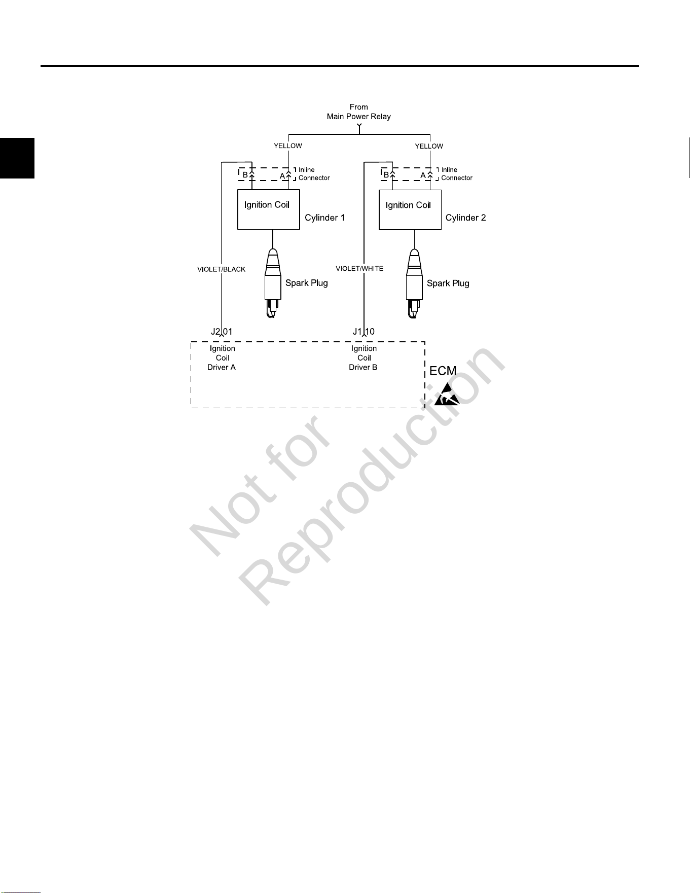
2
60
DTC P0351/P0352 CYLINDER 1 OR CYLINDER 2 IGNITION COIL FAULT
Circuit Description
Each ignition coil has an ignition (B+ voltage) and a
ground circuit. The ECM controls the ignition coil by
completing the ground circuit as needed.
The DTCs indicate which ignition coil is faulty. When
an ignition coil fault is set the ECM also shuts down the
fuel injector for the same cylinder. The engine continues
to run on one cylinder if no fault is set for the opposite
cylinder.
Diagnostic Aids
Check for the following conditions:
1. Poor ECM connection.
2. Inspect wire harness connectors for backed out
terminals, improper mating, broken locks, improperly
formed or damaged terminals, and poor terminal to
wire connection.
3. Damaged wire harness and/or connectors. If harness
appears to be OK, shake or wiggle wire harness
and/or connector with DVOM attached. Radical
voltage changes can indicate the location of the fault
condition.
4. Open fuse in fuse block.
Always clear DTCs after performing repairs.
Not for
Reproduction
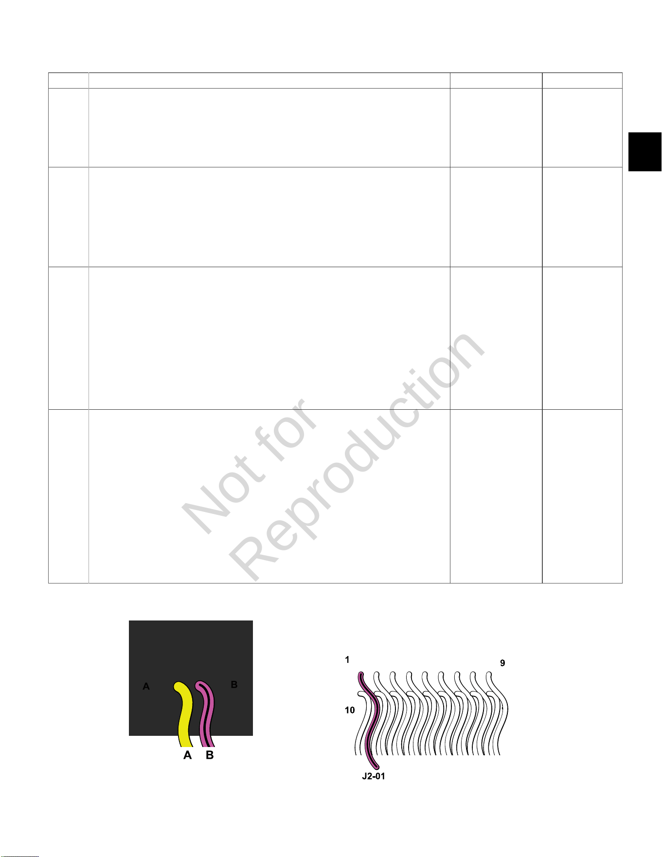
2
61
DTC P0351 Cylinder 1 Ignition Coil Fault (Non-Scan Diagnostics)
Step Action Yes No
1 1. Disconnect and reconnect cylinder 1 ignition coil and ECM J2 (Black) connectors.
2. Turn Ignition ON, Engine OFF. Clear codes.
3. Turn Ignition OFF, and then back ON.
4. Does DTC return?
Go to step 2. Problem corrected.
2 1. Turn Ignition OFF.
2. Disconnect ignition coil connector.
3. Install Briggs & Stratton Noid Light (Part No. 19623).
4. Observe Noid Light while cranking engine.
5. Does Noid Light flash (but very dimly)?
Circuit OK.
Replace ignition coil.
Go to step 3.
3 1. Turn Ignition OFF.
2. Back probe (using fused patch cord) terminal A (Yellow wire) of ignition coil connector.
3. Connect terminal A back probe to red meter test lead on DVOM.
4. Connect black meter test lead on DVOM to a known good ground.
5. Set DVOM to read volts DC.
6. Turn Ignition ON, Engine OFF.
7. Does DVOM read 12.2-13.5 volts DC?
Go to step 4. Reading is below
12.2 volts DC.
Perform visual and
continuity check
of Main Power
Relay and 20
amp Battery fuse
(Yellow).
4 1. Turn Ignition OFF.
2. Remove probe from terminal A, and back probe terminal B (Violet/Black wire) of ignition
coil connector.
3. Connect terminal B back probe to red meter test lead on DVOM.
4. Disconnect ECM J2 connector.
5. Back probe terminal J2-01 (Violet/Black wire) of ECM J2 connector.
6. Connect terminal J2-01 back probe to black meter test lead on DVOM.
7. Set DVOM to read resistance.
8. Does DVOM read 0.5 ohms or less?
Replace ignition coil. Resistance reading
is above 0.5 ohms.
Repair or replace
EFI wire harness.
Cylinder 1 Ignition Coil Connector ECM J2 (Black) Connector
Not for
Reproduction
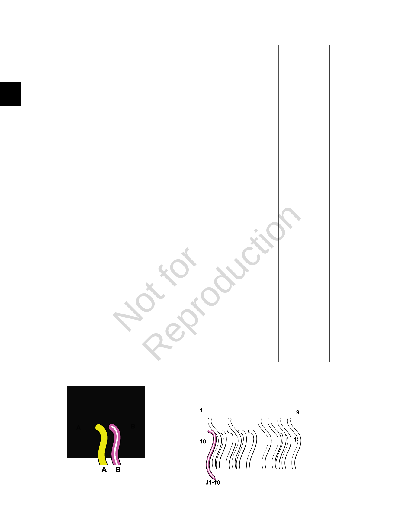
2
62
DTC P0352 Cylinder 2 Ignition Coil Fault (Non-Scan Diagnostics)
Step Action Yes No
1 1. Disconnect and reconnect cylinder 2 ignition coil and ECM J1 (Grey) connectors.
2. Turn Ignition ON, Engine OFF. Clear codes.
3. Turn Ignition OFF, and then back ON.
4. Does DTC return?
Go to step 2. Problem corrected.
2 1. Turn Ignition OFF.
2. Disconnect ignition coil connector.
3. Install Briggs & Stratton Noid Light (Part No. 19623).
4. Observe Noid Light while cranking engine.
5. Does Noid Light flash (but very dimly)?
Circuit OK.
Replace ignition
coil.
Go to step 3.
3 1. Turn Ignition OFF.
2. Back probe (using fused patch cord) terminal A (Yellow wire) of ignition coil connector.
3. Connect terminal A back probe to red meter test lead on DVOM.
4. Connect black meter test lead on DVOM to a known good ground.
5. Set DVOM to read volts DC.
6. Turn Ignition ON, Engine OFF.
7. Does DVOM read 12.2-13.5 volts DC?
Go to step 4. Reading is below
12.2 volts DC.
Perform visual and
continuity check of
Main Power Relay
and 20 amp Battery
fuse (Yellow).
4 1. Turn Ignition OFF.
2. Remove probe from terminal A, and back probe terminal B ((Violet/White wire) of ignition coil
connector.
3. Connect terminal B back probe to red meter test lead on DVOM.
4. Disconnect ECM J1 connector.
5. Back probe terminal J1-10 (Violet/White wire) of ECM J1 connector.
6. Connect terminal J1-10 back probe to black meter test lead on DVOM.
7. Set DVOM to read resistance.
8. Does DVOM read 0.5 ohms or less?
Replace
ignition coil.
Resistance reading
is above 0.5 ohms.
Repair or replace
EFI wire harness.
Cylinder 2 Ignition Coil Connector ECM J1 (Grey) Connector
Not for
Reproduction
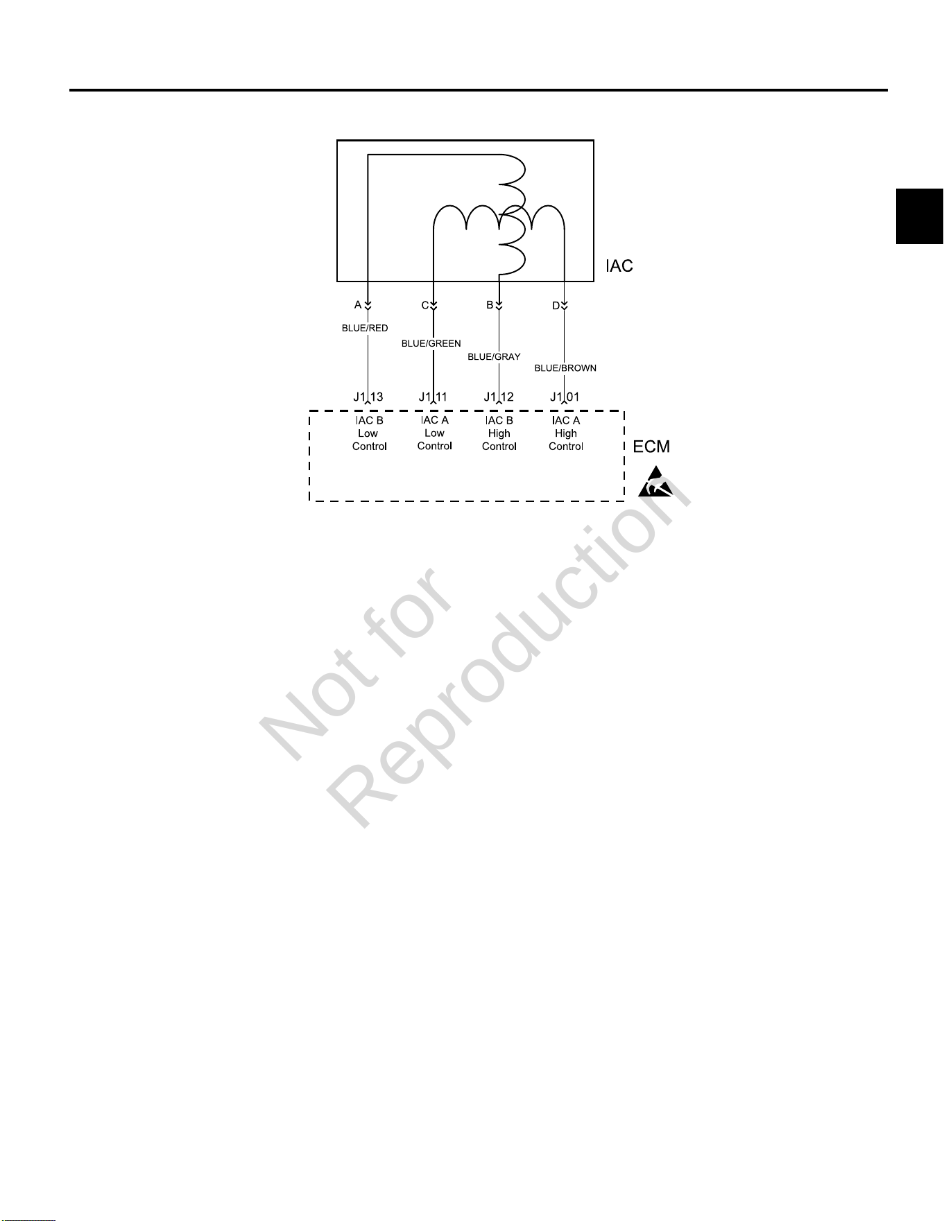
2
63
DTC P0505 IDLE AIR CONTROL (IAC) MALFUNCTION
Circuit Description
The ECM controls idle speed to a calibrated RPM based
on sensor inputs and actual engine RPM. The ECM uses
four circuits to move the IAC valve.
The movement of the IAC valve varies the amount of air
flow bypassing the throttle plates. The ECM controls idle
speed by determining the position of the IAC valve.
Diagnostic Aids
Check for the following conditions:
1. Poor connection or damaged harness. Inspect
the ECM harness and connectors for improper
mating, broken locks, improperly formed or damaged
terminals, poor terminal to wire connection and
damaged harness.
2. Check for vacuum leaks, disconnected or brittle
vacuum hoses, cuts, etc. Examine manifold and
throttle body gaskets for proper seal. Check for
cracked intake manifold.
3. Check for poor connections, opens or shorts to
ground in the IAC circuit.
4. Check for a stuck IAC valve that will not respond
to the ECM, a throttle stop screw that has been
tampered with, or a damaged throttle body or linkage.
Always clear DTCs after performing repairs.
Not for
Reproduction
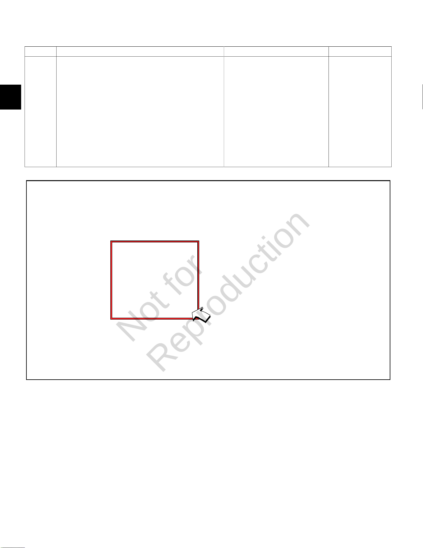
2
64
DTC P0505 Idle Air Control (IAC) Malfunction (Scan Diagnostics)
Step Action Yes No
1 1. Select theDashboardicon in the left sidebar to view
theDealertab.
2. Observe the Engine Speed display while idling.
NOTE:An Engine Speed display can also be viewed under
theTroubleshootingtab.
3. Is reading 750-950 RPM?
NOTE:Cold engine temperatures and low battery voltages can
cause high engine idle speeds. For example, at -18° F (-28° C),
idle speed can be as high as 1350 RPM, while low battery voltages
at normal engine operating temperatures can cause the engine idle
speed to reach 1200 RPM.
IAC circuit OK. Go to DTC P0505 Non-
Scan Diagnostics.
Not for
Reproduction

2
65
DTC P0505 Idle Air Control (IAC) Malfunction (Non-Scan Diagnostics)
Step Action Yes No
1 1. Disconnect and reconnect IAC and TPS connectors.
2. Turn Ignition ON, Engine OFF.
3. Clear codes.
4. Turn Ignition OFF, and then back ON.
5. Does DTC return?
Go to step 2. Problem corrected.
2 1. Start engine and allow it to warm up for 5 minutes.
2. When engine idle speed is stabilized, use tachometer to record RPM.
3. Is tachometer reading 750-950 RPM?
NOTE:Cold engine temperatures and low battery voltages can cause high engine
idle speeds. For example, at -18° F (-28° C), idle speed can be as high as 1350
RPM, while low battery voltages at normal engine operating temperatures can
cause the engine idle speed to reach 1200 RPM.
Look for
intermittent
conditions.
Go to step 3.
3 1. Turn Ignition OFF.
2. Back probe terminal 3 (Pink/Black wire) of TPS connector.
3. Connect terminal 3 back probe to red meter test lead on DVOM.
4. Connect black meter test lead on DVOM to a known good ground.
5. Set DVOM to read volts DC.
6. Start engine and run at idle speed.
7. Does DVOM read 0.5-0.75 volts DC?
Go to step 4. Reset TPS.
SeeTPS Removal/Installation/
AdjustmentinSECTION 5 -
REMOVAL/INSTALLATION.
4 1. Turn Ignition OFF.
2. Remove IAC from throttle body and inspect for stuck pintel or carbon build up in
IAC port.
3. Are either of these conditions found?
Clean or repair
as necessary.
Return to step
2 and repeat
test procedure.
Inspect for intake tract leaks
after the throttle body.
TPS Connector
Not for
Reproduction
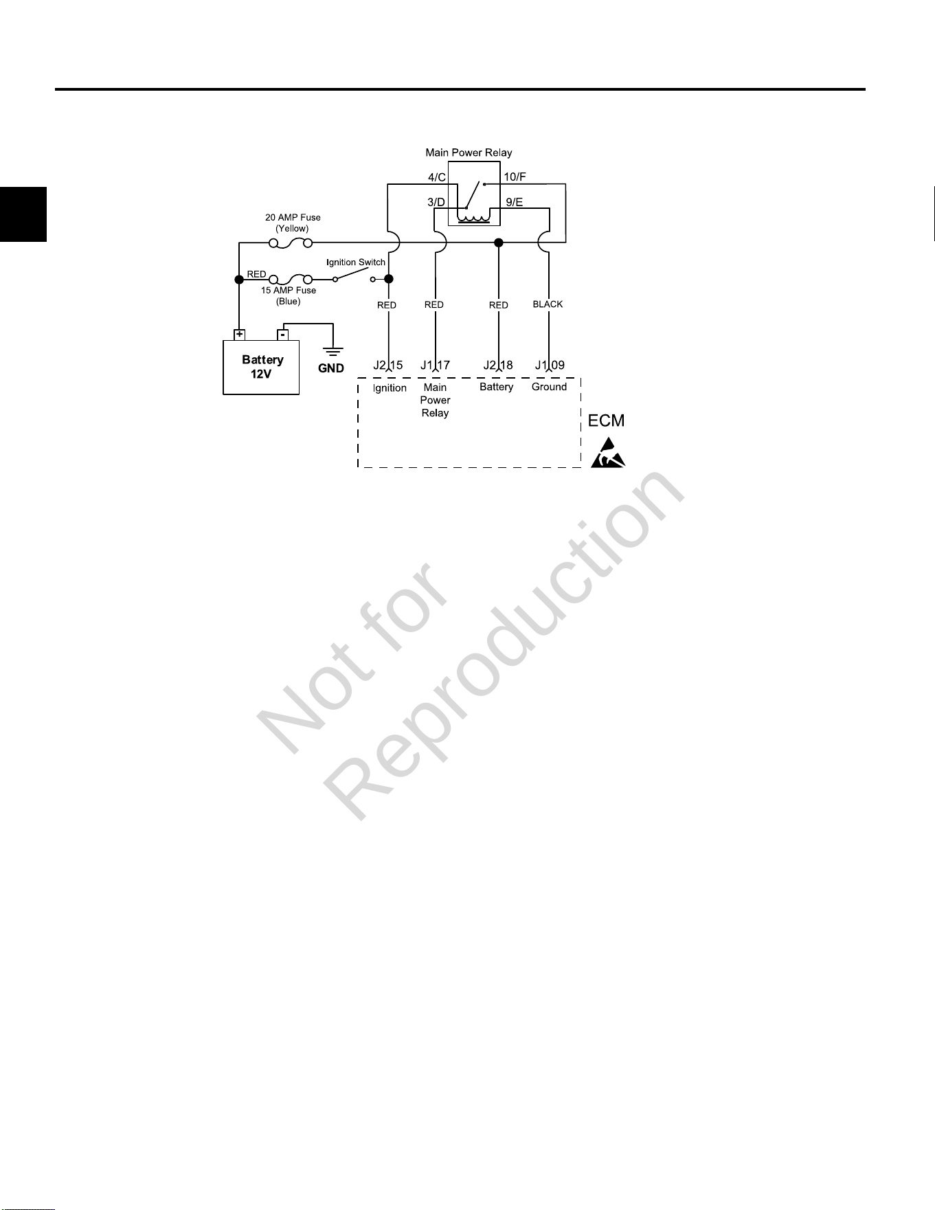
2
66
DTC P0562/P0563 SYSTEM VOLTAGE
Circuit Description
The EFI system operates with a battery voltage of 9-16
volts. If the system voltage drops below 6.2 volts the ECM
will reset. During normal operation, the MIL is illuminated
if the voltage is below 9 volts (setting P0562) or above 16
volts (setting P0563) for a specified amount of time.
To determine the system voltage to the ECM, take a
voltage measurement at terminal J2-18. If the voltage is
not within 0.01 volt of the measurement obtained at the
battery measuring between the positive (+) and negative
(-) posts with a DVOM, determine the fault associated
with circuit J2-18.
Similarly, you should be able to measure battery voltage
at terminal J2-15 with Ignition ON, Engine OFF.
To further diagnose system voltage faults, see Section
7 of the Briggs & Stratton Intek V-Twin Cylinder OHV
Repair Manual.
Diagnostic Aids
Check for the following conditions:
1. Poor ECM connection. Inspect harness connectors
for backed out terminals, improper mating, broken
locks, improperly formed or damaged terminals, and
poor terminal to wire connection.
2. Damaged wire harness and/or connectors.
Always clear DTCs after performing repairs.
Not for
Reproduction
2
67
DTC P0562 System Voltage Low (Scan Diagnostics)
Step Action Yes No
1 1. Select theDashboardicon in the left sidebar to view
theDealertab.
2. Observe the Ignition Voltage display with or without the engine
running.
3. Is reading 9.0-15.0 volts DC?
System voltage OK. Go to step 2.
2 Is reading below 9.0 volts DC? Go to DTC P0562 Non-Scan Diagnostics. -
Not for
Reproduction

2
68
DTC P0562 System Voltage Low (Non-Scan Diagnostics)
Step Action Yes No
1 1. Disconnect and reconnect ECM J2 (Black) connector.
2. Turn Ignition ON, Engine OFF.
3. Clear codes.
4. Turn Ignition OFF, and then back ON.
5. Does DTC return?
Go to step 2. Problem corrected.
2 1. Turn Ignition OFF.
2. Connect red meter test lead on DVOM to battery positive (+) post.
3. Connect black meter test lead on DVOM to battery negative (-) post.
4. Set DVOM to read volts DC.
5. Does DVOM read 12.2-14.5 volts DC?
Go to step 3. Go to step 5.
3 1. Back probe terminal J2-18 (Red wire) of ECM J2 connector.
2. Connect terminal J2-18 back probe to red meter test lead on DVOM.
3. Connect black meter test lead on DVOM to a known good ground.
4. Turn Ignition ON, Engine OFF.
5. Observe voltage on DVOM.
6. Is reading within 0.5 volts of battery voltage?
Go to step 4. Go to step 7.
4 1. Turn Ignition OFF.
2. Back probe terminal J2-15 (Red wire) of ECM J2 connector.
3. Connect terminal J2-15 back probe to red meter test lead on DVOM.
4. Connect black meter test lead on DVOM to a known good ground.
5. Turn Ignition ON, Engine OFF.
6. Observe voltage on DVOM.
7. Is voltage within 0.5 volt of battery voltage?
Go to step 5. Go to step 8.
5 1. Check charging system. See the Briggs & Stratton Intek V-Twin Cylinder OHV
Repair Manual.
2. Is charging system OK?
Go to step 6. Repair charging
system.
6 1. Check battery and cables for damage, corrosion, and loose connections.
2. Is a problem found?
Repair as necessary. Replace battery.
7 1. Disconnect ECM J2 connector.
2. Back probe terminal J2-18 (Red wire) of ECM J2 connector.
3. Connect terminal J2-18 back probe to red meter test lead on DVOM.
4. Connect black meter test lead on DVOM to B+.
5. Set DVOM to read resistance.
6. Observe reading on DVOM.
7. Is resistance 0.5 ohms or less?
- Repair as
necessary.
Continued...
Not for
Reproduction
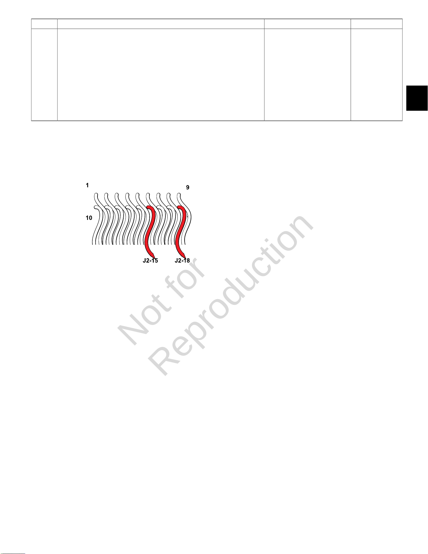
2
69
Step Action Yes No
8 1. Disconnect ECM J2 connector.
2. Back probe terminal J2-15 (Red wire) of ECM J2 connector.
3. Connect terminal J2-15 back probe to red meter test lead on DVOM.
4. Connect black meter test lead on DVOM to B+.
5. Set DVOM to read resistance.
6. Observe reading on DVOM.
7. Is resistance 0.5 ohms or less?
- Repair as
necessary.
ECM J2 (Black) Connector
Not for
Reproduction
2
70
DTC P0563 System Voltage High (Scan Diagnostics)
Step Action Yes No
1 1. Select theDashboardicon in the left sidebar to view
theDealertab.
2. Observe the Ignition Voltage display with or without the engine
running.
3. Is reading 9.0-15.0 volts DC?
System voltage OK. Go to step 2.
2 Is reading above 15.0 volts DC? Go to DTC P0563 Non-Scan Diagnostics. -
DTC P0563 System Voltage High (Non-Scan Diagnostics)
Step Action Yes No
1 1. Connect red meter test lead on DVOM to battery positive (+) post.
2. Connect black meter test lead on DVOM to battery negative (-) post.
3. Set DVOM to read volts DC.
4. Start and run engine at full speed (3600 RPM).
5. Observe voltage on DVOM.
6. Is reading 12.2-14.5 volts DC?
System voltage OK. Reading is above
15 volts. Check
charging system.
See the Briggs &
Stratton Intek V-
Twin Cylinder OHV
Repair Manual.
Not for
Reproduction
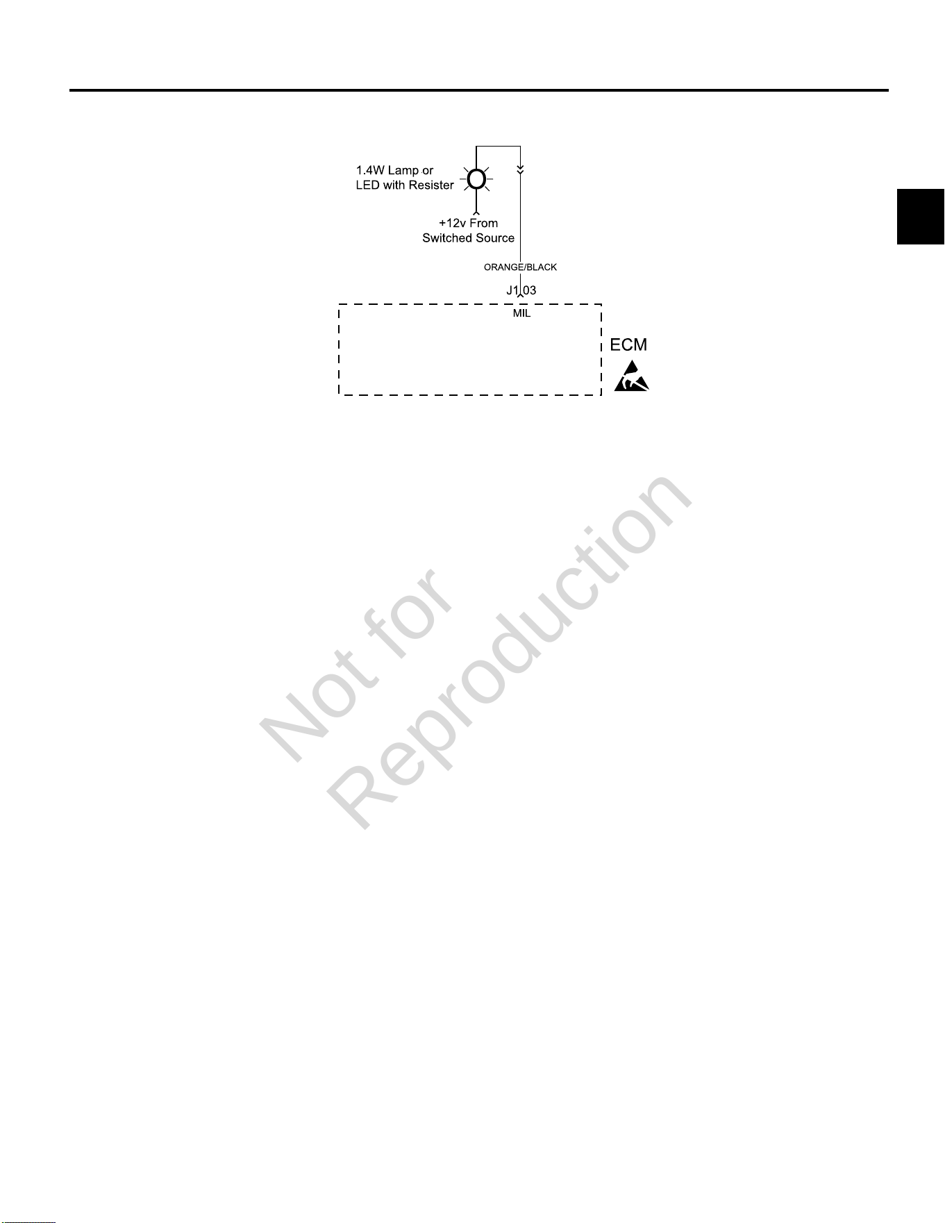
2
71
DTC P0650 MALFUNCTION INDICATOR LAMP (MIL) MALFUNCTION
Circuit Description
The MIL gets 12v B+ when the ignition is in the ON or
RUN position. The ECM completes a ground signal to
illuminate the MIL with Ignition ON, Engine OFF. The
ECM also completes the ground signal to activate the
lamp if a DTC is set. If the malfunction clears, the lamp
is extinguished and the DTC is stored in the ECM as a
historic code.
Diagnostic Aids
Check for the following conditions:
1. Poor ECM connection. Inspect wire harness
connectors for backed out terminals, improper
mating, broken locks, improperly formed or damaged
terminals, and poor terminal to wire connection.
2. Damaged wire harness. If wire harness appears to be
OK, observe the MIL display while moving connectors
and wiring harnesses related to the MIL. A change in
the MIL display will indicate the location of the fault.
Always clear DTCs after performing repairs.
Not for
Reproduction
2
72
DTC P0650 MIL Malfunction (Scan Diagnostics)
Step Action Yes No
1 1. Select theDashboardicon in the left sidebar to view
theDealertab.
2. Observe the Current codes display.
NOTE:A Current codes display can also be viewed under
theTroubleshootingtab.
3. Does the display indicate that a current code exists?
Go to step 3. Go to step 2.
2 1. Disconnect MAP sensor connector, ignition coil connector, or
any other connector that will set a DTC. Start and run engine.
2. Does the Code(s) Current display indicate that a current code
exists?
Go to step 3. -
3 Is MIL illuminated? System OK. Go to DTC P0650 Non-
Scan Diagnostics.
Not for
Reproduction
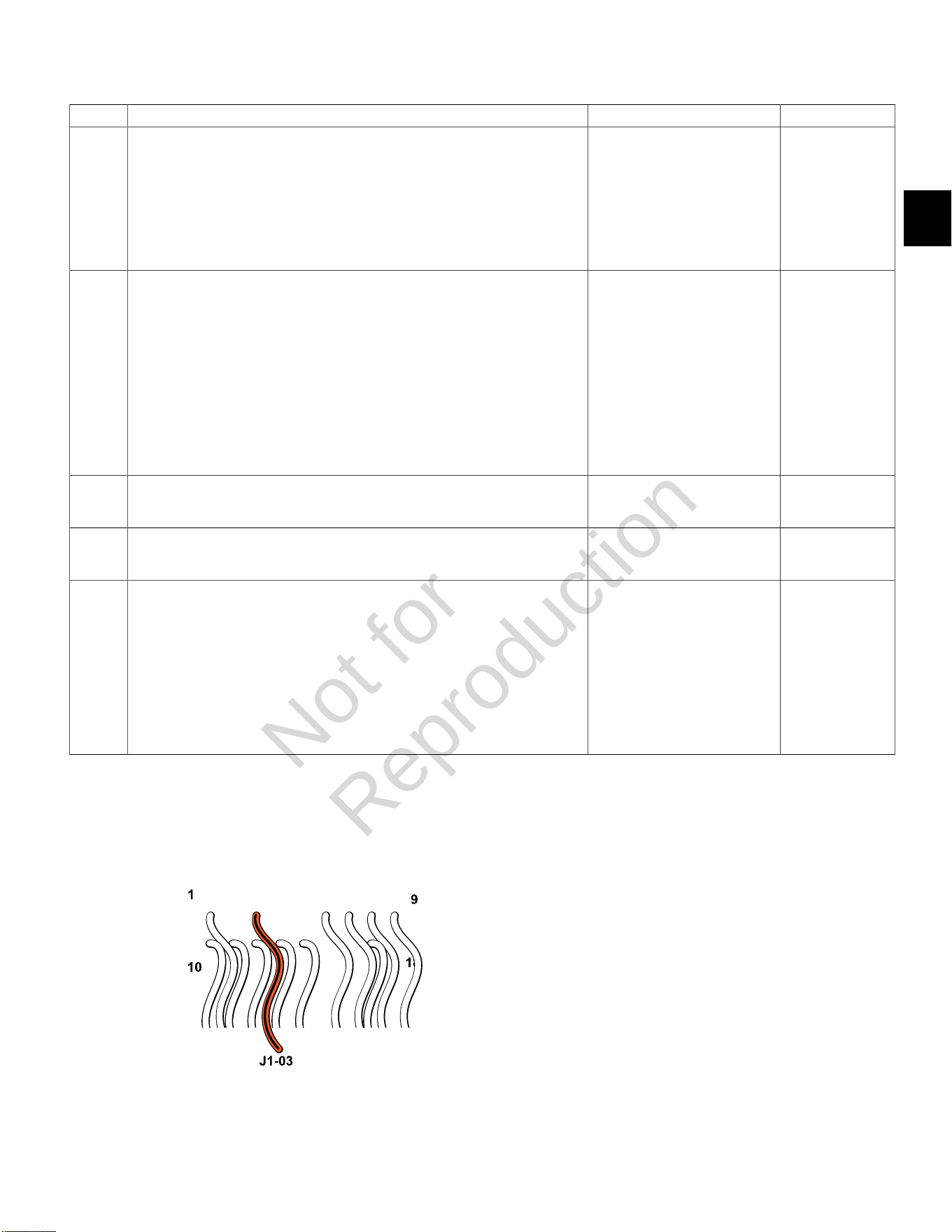
2
73
DTC P0650 MIL Malfunction (Non-Scan Diagnostics)
Step Action Yes No
1 1. Disconnect and reconnect ECM J1 (Grey) connector.
2. Turn Ignition ON, Engine OFF.
3. Clear codes.
4. Turn Ignition OFF, and then back ON.
5. Does DTC return?
Go to step 2. Problem corrected.
2 1. Turn Ignition OFF.
2. Connect red meter test lead on DVOM to ignition side of MIL.
3. Connect black meter test lead on DVOM to a known good ground.
4. Set DVOM to read volts DC.
5. Turn Ignition ON, Engine OFF.
6. Observe voltage on DVOM.
7. Is reading 12.2-14.5 volts DC?
Go to step 4. Go to step 3.
3 1. Identify and locate voltage interruption between MIL and B+.
2. Is interruption found?
Repair as necessary. Go to step 5.
4 1. Check continuity of MIL.
2. Is continuity good?
Go to step 5. Repair faulty MIL
connections or
replace faulty MIL.
5 1. Back probe terminal J1-03 (Orange/Black wire) of ECM J1 connector.
2. Connect terminal J1-03 back probe to red meter test lead on DVOM.
3. Connect black meter test lead on DVOM to ignition side of MIL.
4. Set DVOM to read resistance.
5. Observe reading on DVOM.
6. Is resistance 0.5 ohms or less?
Repair faulty ECM connections
or replace faulty ECM.
-
ECM J1 (Grey) Connector
Not for
Reproduction
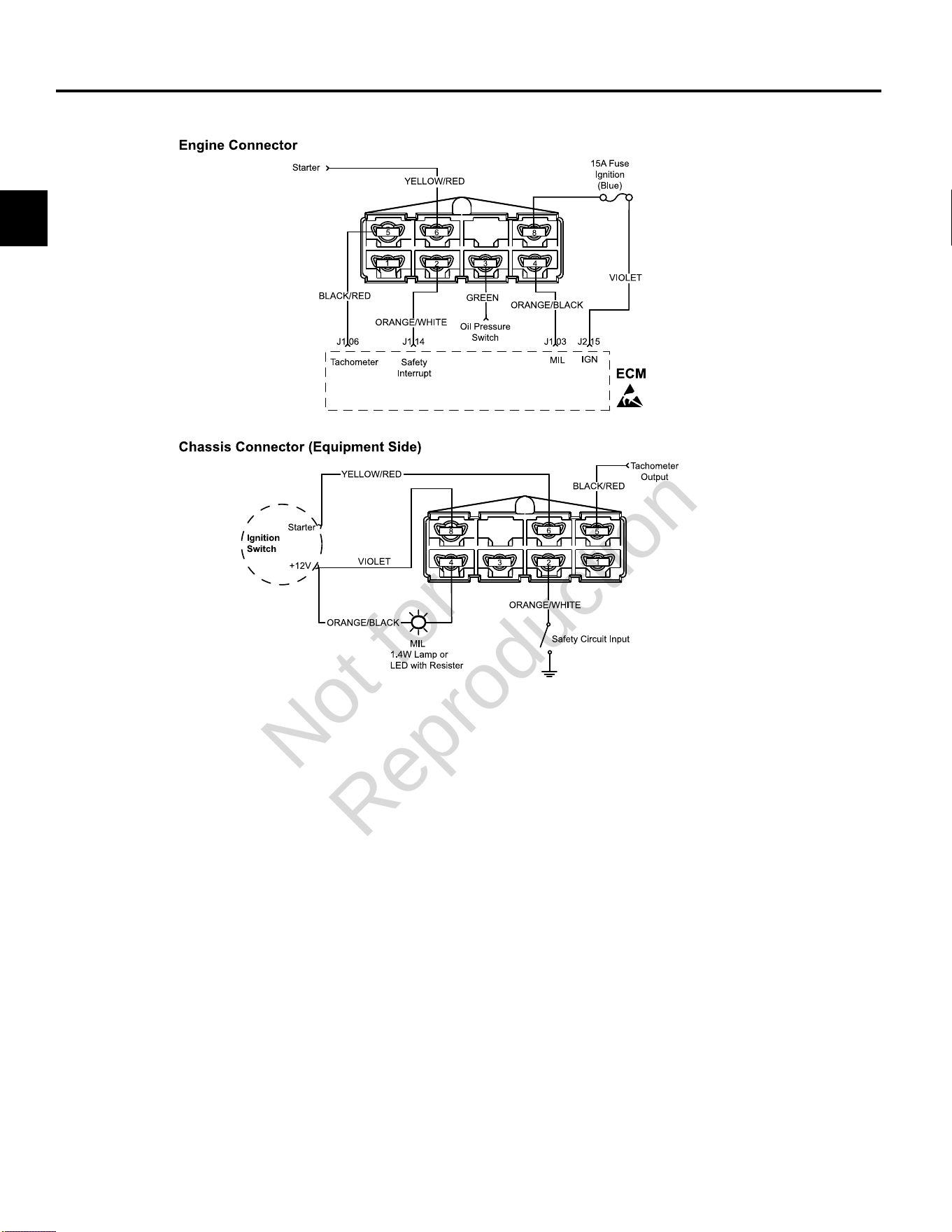
2
74
DTC P1693/P1694TACHOMETER MALFUNCTION
Diagnostic Aids
Check for the following conditions:
1. Poor ECM connection.
2. Inspect wire harness connectors for backed out
terminals, improper mating, broken locks, improperly
formed or damaged terminals, and poor terminal to
wire connection.
3. Damaged wire harness and/or connectors. If harness
appears to be OK, shake or wiggle wire harness
and/or connector with DVOM attached. Radical
voltage changes can indicate the location of the fault
condition.
Always clear DTCs after performing repairs.
Not for
Reproduction

2
75
DTC P1693 Driver Circuit Shorted to Ground (Non-Scan Diagnostics)
Step Action Yes No
1 1. Disconnect and reconnect engine, tachometer and ECM J1 (Grey)
connectors.
2. Turn Ignition ON, Engine OFF.
3. Clear codes.
4. Turn Ignition OFF, and then back ON.
5. Does DTC return?
Go to step 2. Problem corrected.
2 1. Turn Ignition OFF.
2. Back probe terminal J1-06 (Black/Red wire) of ECM connector.
3. Connect terminal J1-06 back probe to red meter test lead on DVOM.
4. Connect black meter test lead on DVOM to a known good ground.
5. Set DVOM to read continuity test.
6. Turn Ignition ON, Engine OFF.
7. Observe continuity on DVOM.
8. Is there continuity to ground?
Replace tachometer, or check
for short to ground on Black/Red
wire of engine connector orwire
of chassis connector (equipment
side) feeding terminal 5.
No problem found.
ECM J1 (Grey) Connector
Not for
Reproduction

2
76
DTC P1694 Driver Circuit Shorted to Power (Non-Scan Diagnostics)
Step Action Yes No
1 1. Disconnect and reconnect engine, tachometer and ECM J1 (Grey)
connectors.
2. Turn Ignition ON, Engine OFF.
3. Clear codes.
4. Turn Ignition OFF, and then back ON.
5. Does DTC return?
Go to step 2. Problem corrected.
2 1. Turn Ignition OFF.
2. Back probe terminal J1-06 (Black/Red wire) of ECM connector.
3. Connect terminal J1-06 back probe to red meter test lead on DVOM.
4. Connect black meter test lead on DVOM to a known good ground.
5. Set DVOM to read volts DC.
6. Turn Ignition ON, Engine OFF.
7. Observe voltage on DVOM.
8. Is reading greater than 9 volts DC?
Replace tachometer, or check
for short to power on Black/Red
wire of engine connector orwire
of chassis connector (equipment
side) feeding terminal 5.
No problem found.
ECM J1 (Grey) Connector
Not for
Reproduction

3
77
SECTION 3 - WIRE SCHEMATICS AND PIN-OUTS
ECM CONNECTOR J1 (GREY) PIN-OUT -------------------------------------------------------------------------------------------------- 78
ECM CONNECTOR J2 (BLACK) PIN-OUT ------------------------------------------------------------------------------------------------- 79
MODEL 490000 EFI ELECTRICAL SCHEMATIC (PAGE 1 OF 2) ------------------------------------------------------------------- 80
MODEL 490000 EFI ELECTRICAL SCHEMATIC (PAGE 2 OF 2) ------------------------------------------------------------------- 81
Model 490000 Engine to Chassis 6-Place Connector Pin-Out (Standard) ---------------------------------------------------- 82
Model 490000 Engine to Chassis 8-Place Connector Pin-Out (Optional) ----------------------------------------------------- 83
MODELS 540000/610000 TURF EFI ELECTRICAL SCHEMATIC (PAGE 1 OF 2) ---------------------------------------------- 84
MODELS 540000/610000 TURF EFI ELECTRICAL SCHEMATIC (PAGE 2 OF 2) ---------------------------------------------- 85
Models 540000/610000 Turf Engine to Chassis 8-Place and 2-Place Connector Pin-Outs (Option 1) ----------------- 86
Models 540000/610000 Turf Engine to Chassis 6-Place and 2-Place Connector Pin-Outs (Option 2) ----------------- 87
MODEL 610000 MARINE EFI ELECTRICAL SCHEMATIC (PAGE 1 OF 2) ------------------------------------------------------- 88
MODEL 610000 MARINE EFI ELECTRICAL SCHEMATIC (PAGE 2 OF 2) ------------------------------------------------------- 89
Model 610000 Marine Engine to Chassis 6-Place and 2-Place Connector Pin-Outs --------------------------------------- 90
MODELS 490000/540000/610000 FUSE/RELAY BLOCK ------------------------------------------------------------------------------ 91
Not for
Reproduction
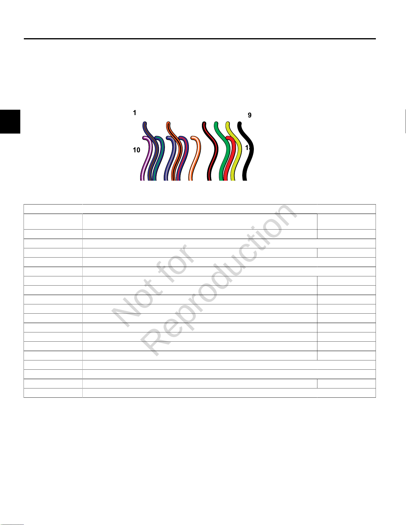
3
78
ECM CONNECTOR J1 (GREY) PIN-OUT
ECM Connector J1 (Grey)
Connector-
Pin Number
Function Wire Color
J1-01 IAC HIGH “A” * Idle Air Control A High Blue/Brown
J1-02 NOT USED
J1-03 MIL Malfunction Indicator Lamp Orange/Black
J1-04 NOT USED
J1-05 NOT USED
J1-06 Tachometer Black/Red
J1-07 CAN Low Used only for ECM Development Green
J1-08 CAN High Used only for ECM Development Yellow
J1-09 GROUND Power Black
J1-10 IGN COIL CYL 2 Engine Spark Timing Coil Cylinder 2 Violet/White
J1-11 IAC LOW “A” * Idle Air Control A Low Blue/Green
J1-12 IAC HIGH “B” * Idle Air Control B High Blue/Grey
J1-13 IAC LOW “B” * Idle Air Control B Low Blue/Red
J1-14 Safety Interrupt Circuit Orange/White
J1-15 NOT USED
J1-16 NOT USED
J1-17 MPR Main Power Relay Red
J1-18 NOT USED
* If Equipped
Not for
Reproduction
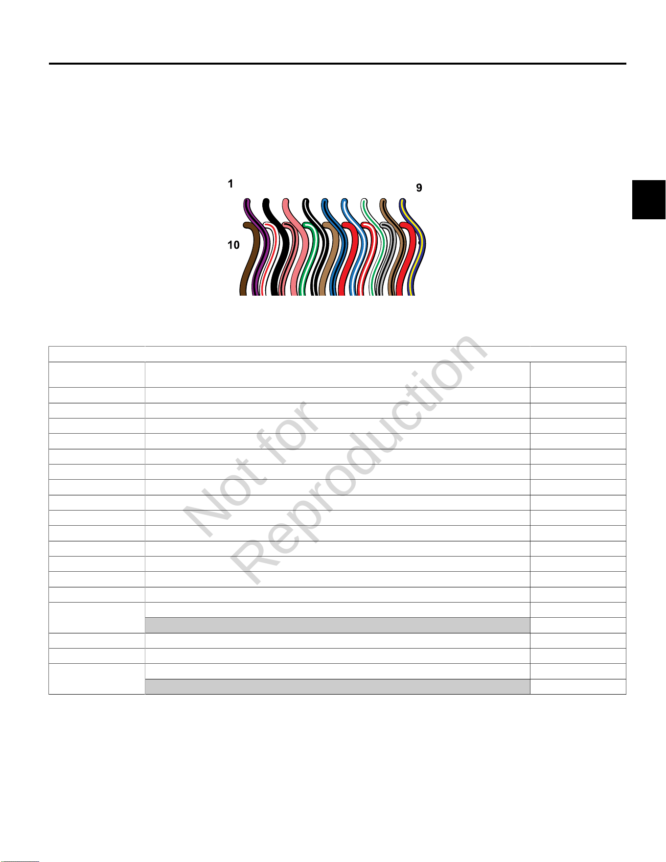
3
79
ECM CONNECTOR J2 (BLACK) PIN-OUT
ECM Connector J2 (Black)
Connector-
Pin Number
Function Wire Color
J2-01 IGN COIL CYL 1 Engine Spark Timing Coil Cylinder 1 Violet/Black
J2-02 GROUND Power Black
J2-03 K-LINE Serial Data Diagnostic Communication Pink
J2-04 CKP High 23X Black/White
J2-05 FUEL INJ CYL 1 Fuel Injector Cylinder 1 Lt.Blue/Black
J2-06 FUEL INJ CYL 2 Fuel Injector Cylinder 2 Lt. Blue/White
J2-07 HO2S HEATER CONTROL* Oxygen Sensor Heater White/Green
J2-08 MAT Manifold Air Temperature Sensor Tan/Black
J2-09 HIGH PRESSURE FUEL PUMP MODULE Fuel Pump Blue/Yellow
J2-10 5V RETURN 5 Volt Return Brown
J2-11 MAP Manifold Absolute Pressure Sensor White/Red
J2-12 TPS * Throttle Position Sensor Pink/Black
J2-13 CKP Low 23X Green/White
J2-14 EHT Engine Head Temperature Sensor Tan
IGN Ignition RedJ2-15
CAUTION:HOT AT KEY ON WHEN BATTERY CONNECTED !!!
J2-16 5V REFERENCE 5 Volt Reference Red/White
J2-17 HO2S SIGNAL Oxygen Sensor Signal Grey/Black
VOLTAGE INPUT +12V Voltage Battery RedJ2-18
CAUTION:HOT AT ALL TIMES WHEN BATTERY CONNECTED !!!
* If Equipped
Not for
Reproduction
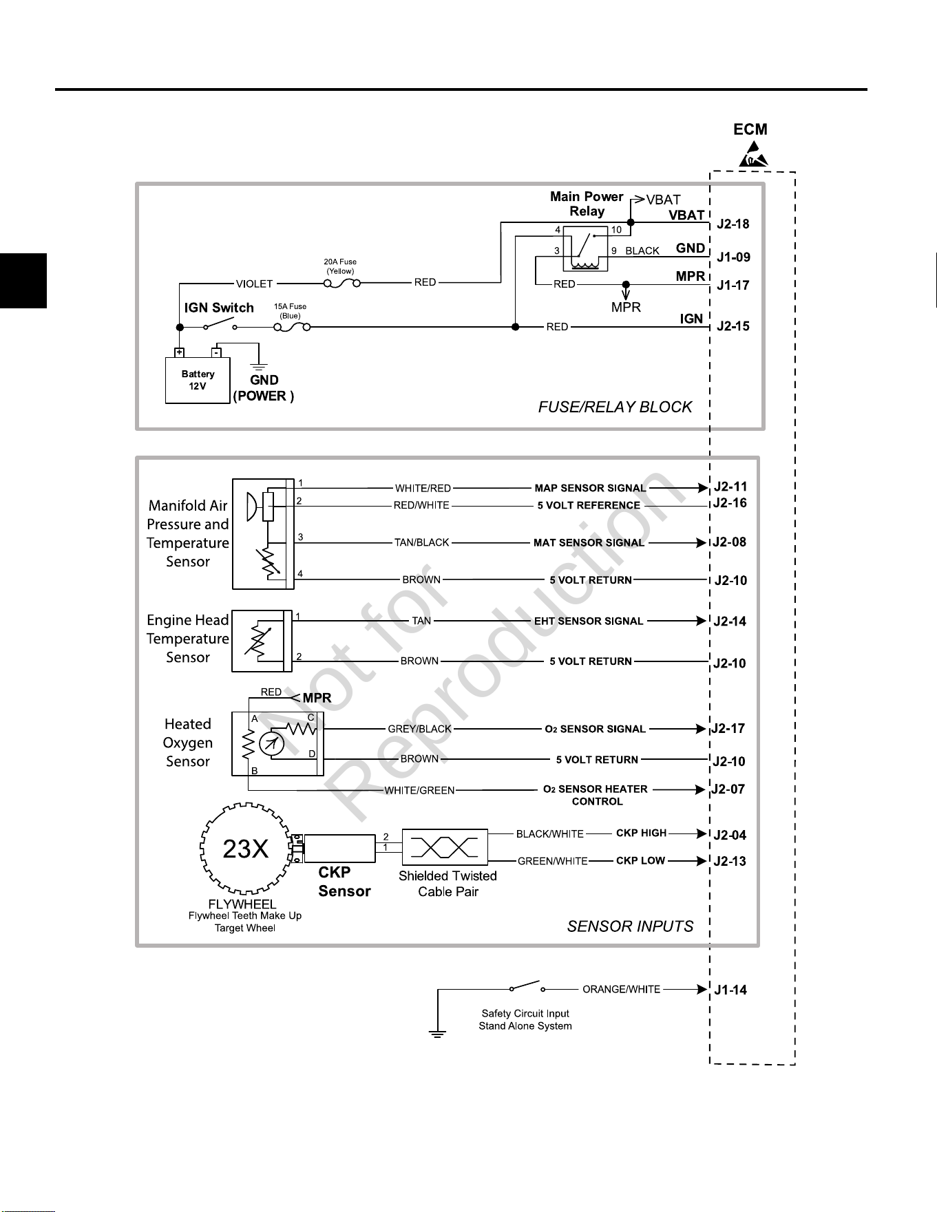
3
80
MODEL 490000 EFI ELECTRICAL SCHEMATIC (PAGE 1 OF 2)
Not for
Reproduction
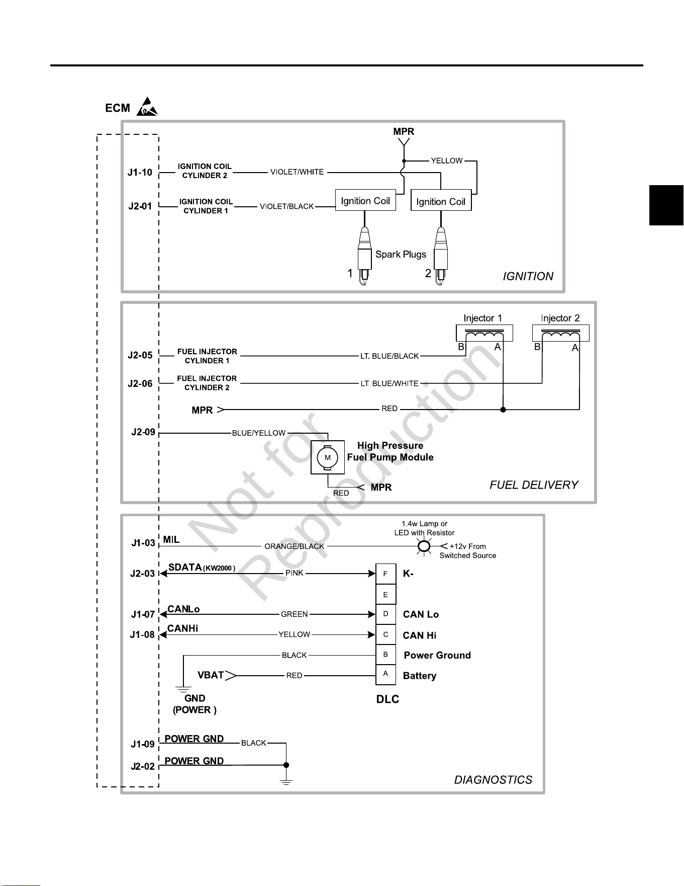
3
81
MODEL 490000 EFI ELECTRICAL SCHEMATIC (PAGE 2 OF 2)
Not for
Reproduction
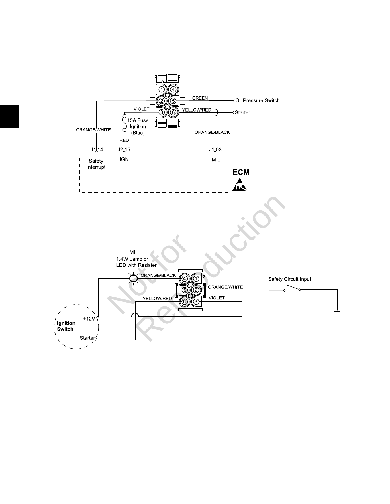
3
82
Model 490000 Engine to Chassis 6-Place Connector Pin-Out (Standard)
Engine Connector
Chassis Connector (Equipment Side)
Not for
Reproduction
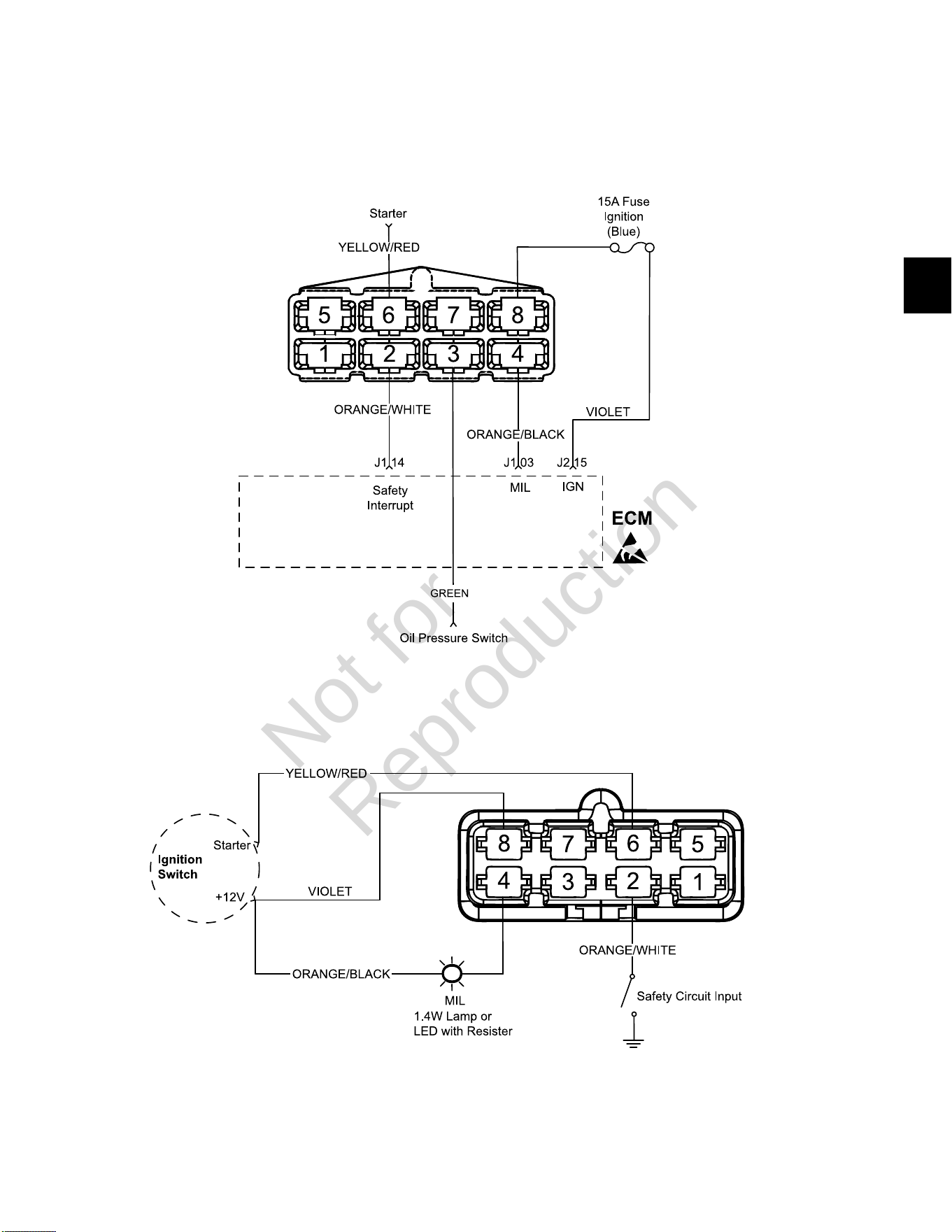
3
83
Model 490000 Engine to Chassis 8-Place Connector Pin-Out (Optional)
Engine Connector
Chassis Connector (Equipment Side)
Not for
Reproduction
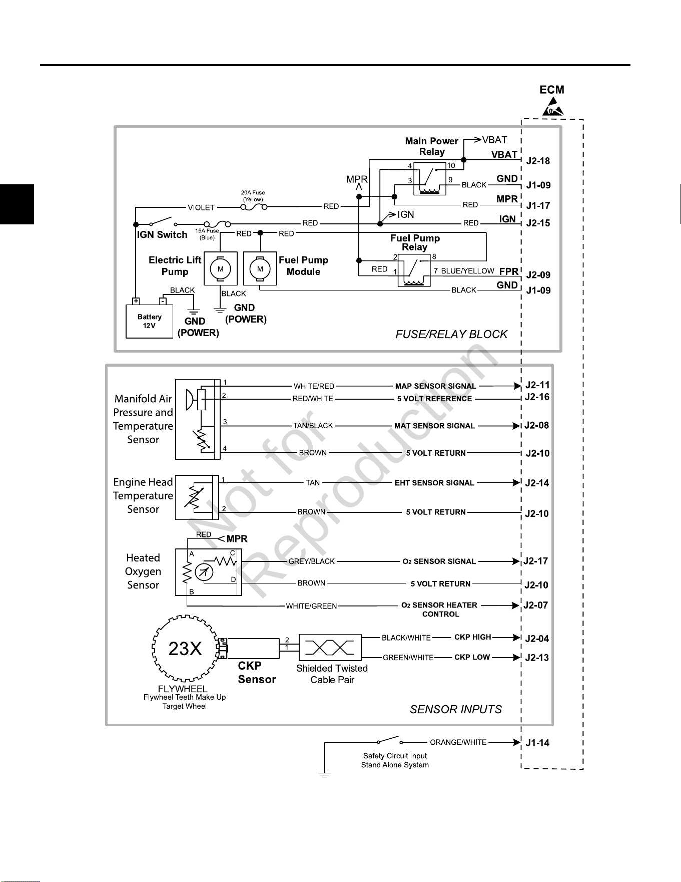
3
84
MODELS 540000/610000 TURF EFI ELECTRICAL SCHEMATIC (PAGE 1 OF 2)
Not for
Reproduction
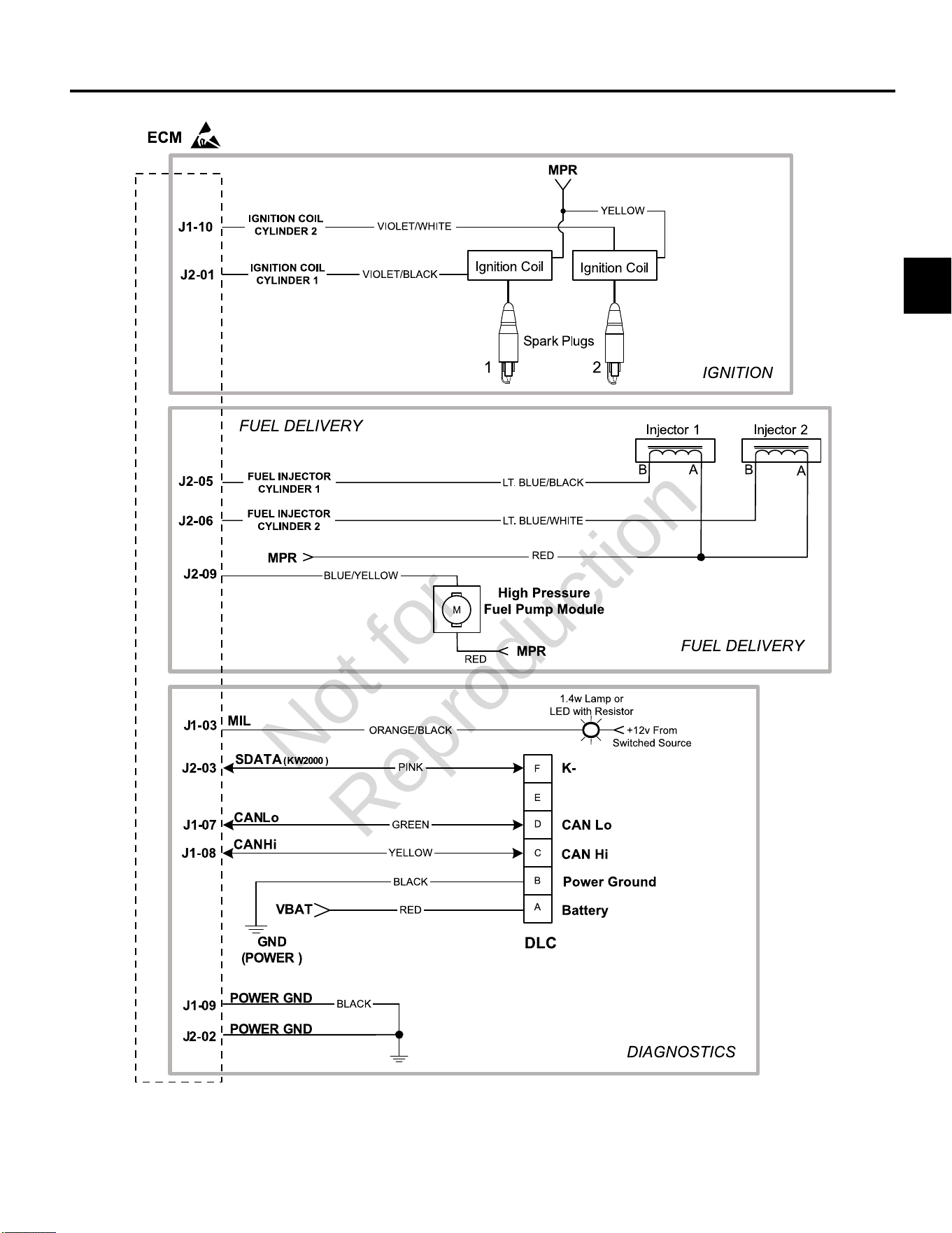
3
85
MODELS 540000/610000 TURF EFI ELECTRICAL SCHEMATIC (PAGE 2 OF 2)
Not for
Reproduction
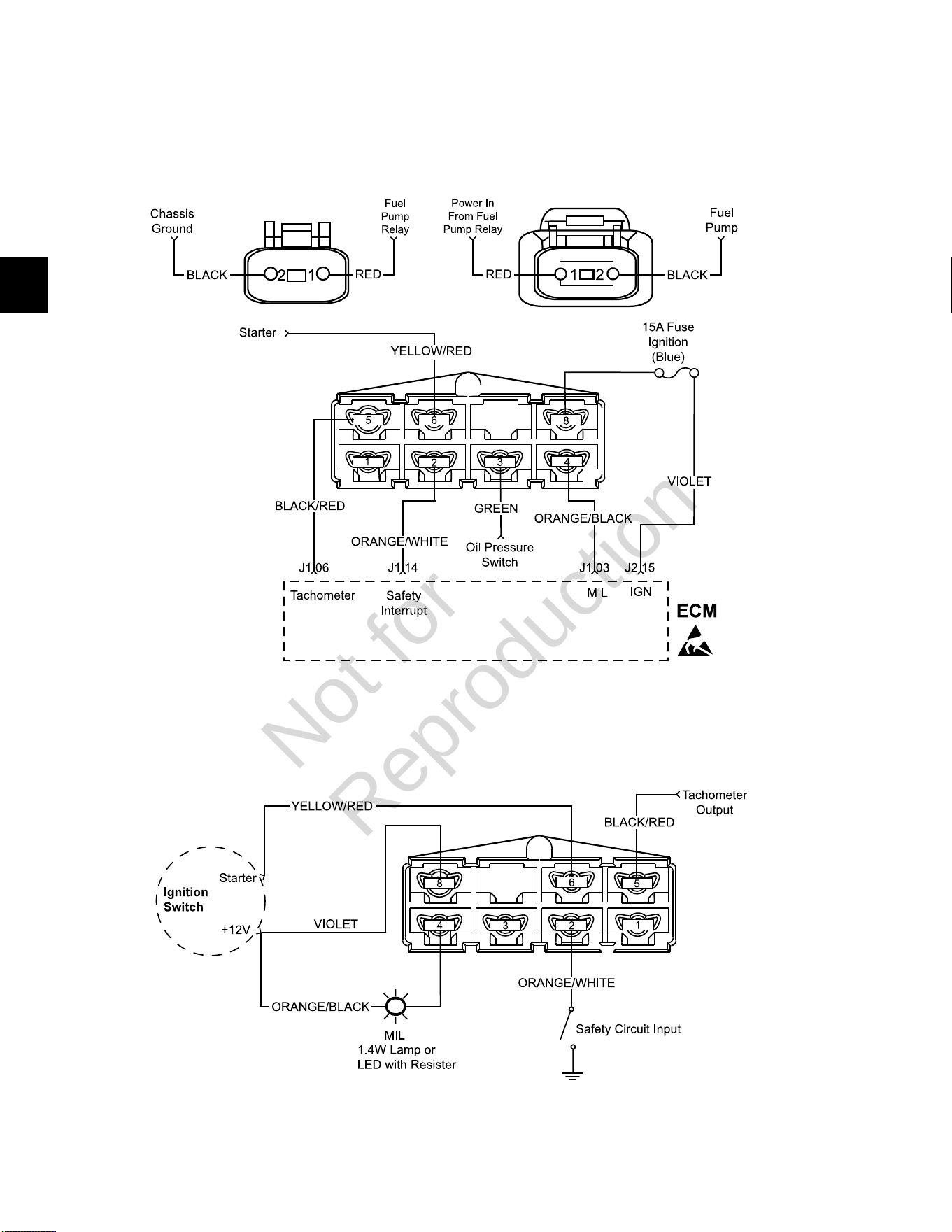
3
86
Models 540000/610000 Turf Engine to Chassis 8-Place and 2-Place Connector Pin-Outs
(Option 1)
Engine Connectors
Chassis Connector (Equipment Side)
Not for
Reproduction
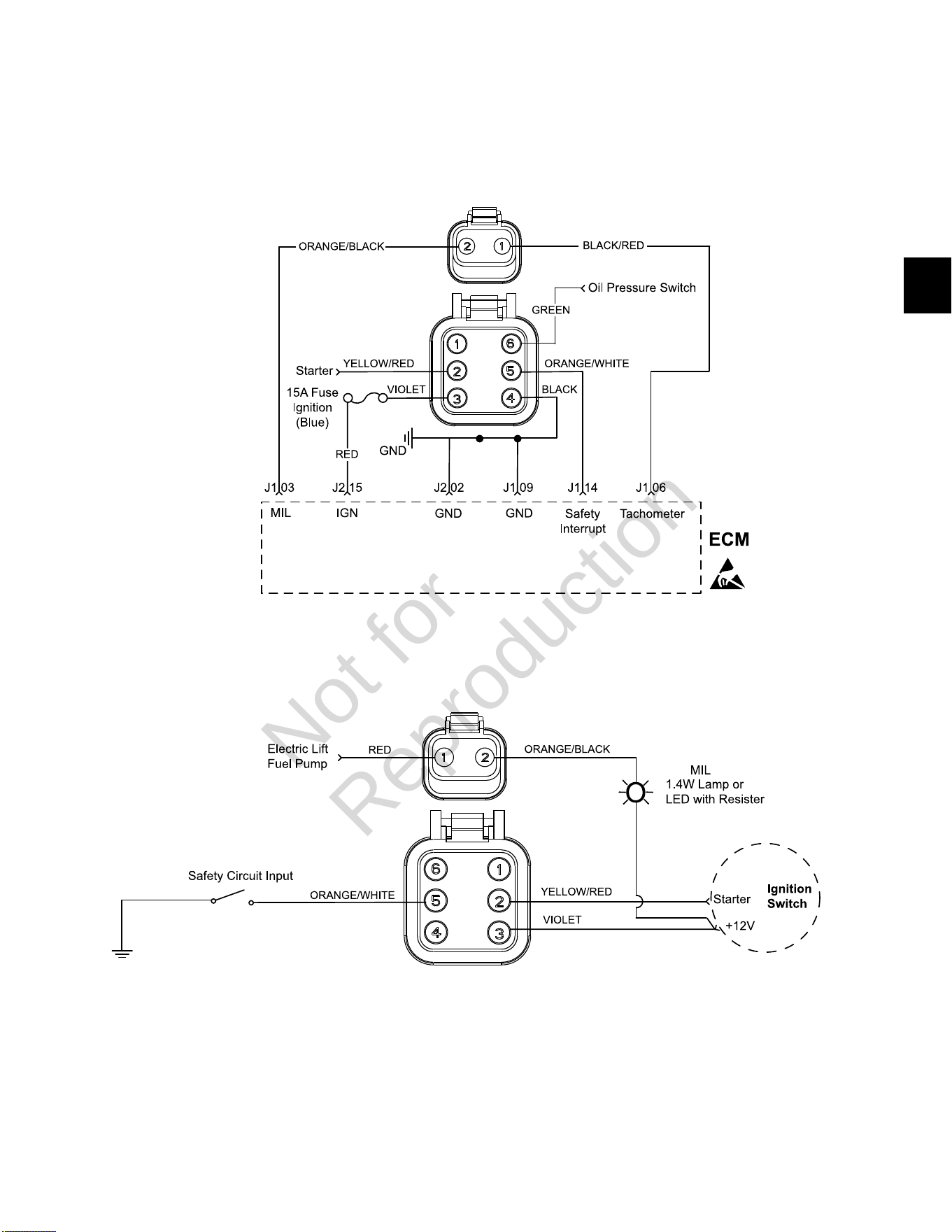
3
87
Models 540000/610000 Turf Engine to Chassis 6-Place and 2-Place Connector Pin-Outs
(Option 2)
Engine Connectors
Chassis Connectors (Equipment Side)
Not for
Reproduction
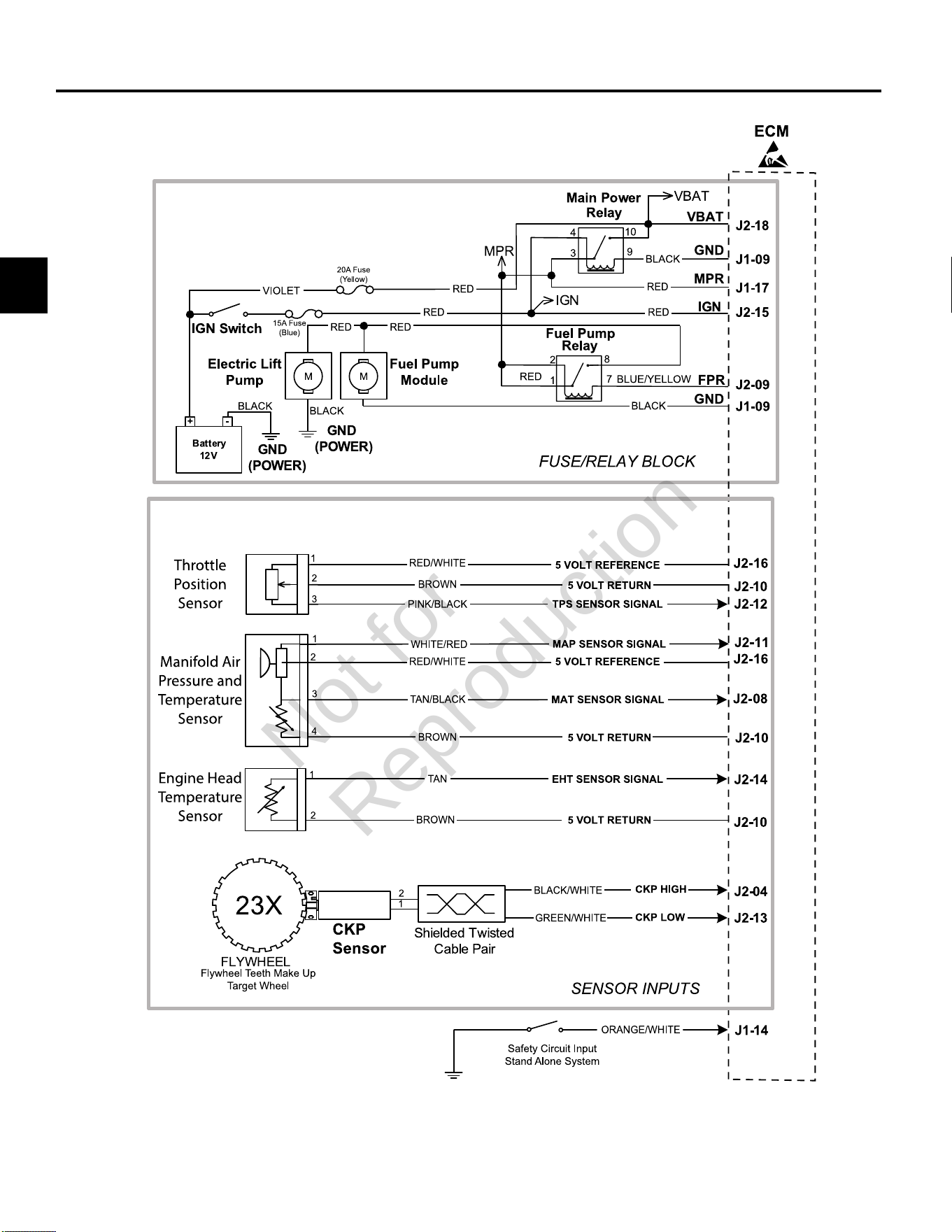
3
88
MODEL 610000 MARINE EFI ELECTRICAL SCHEMATIC (PAGE 1 OF 2)
Not for
Reproduction
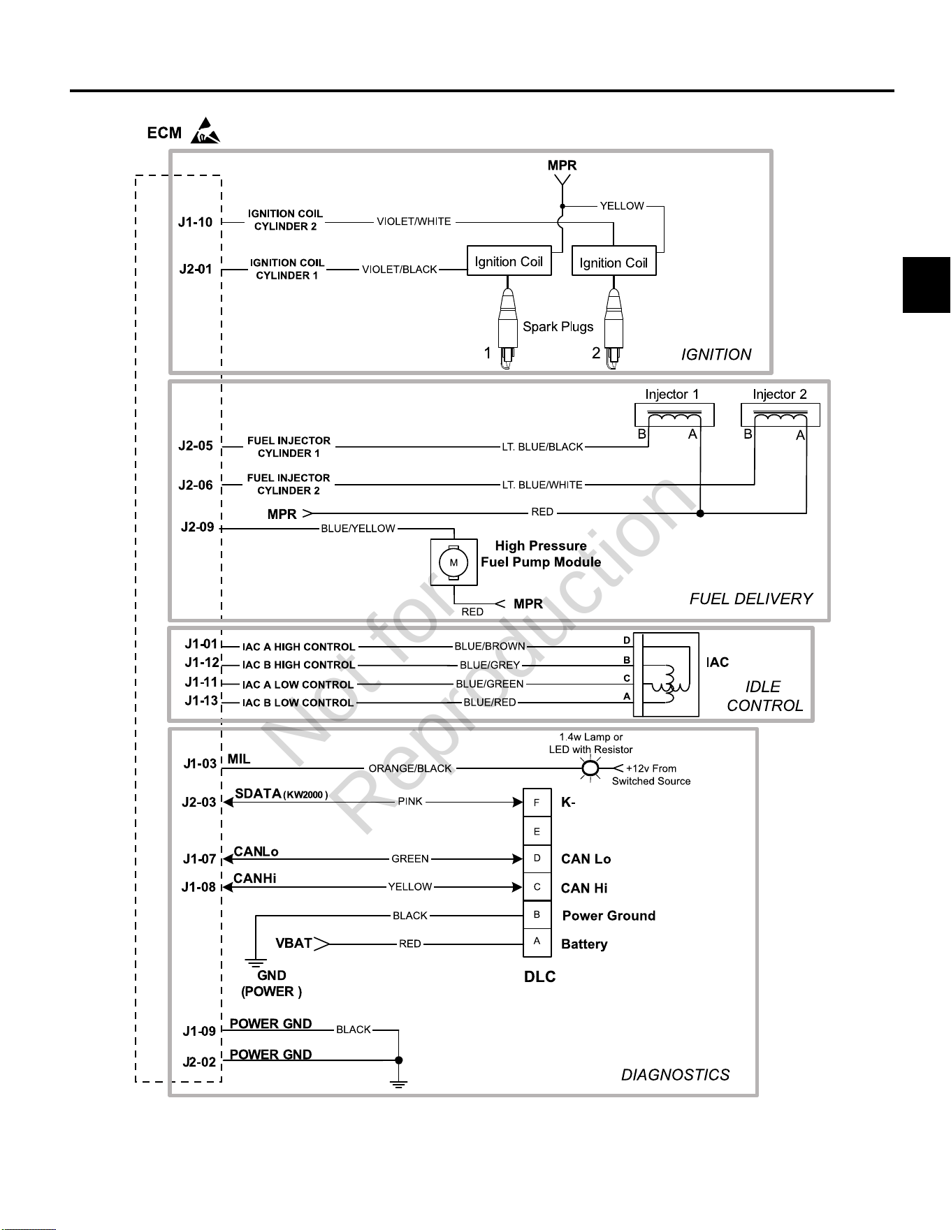
3
89
MODEL 610000 MARINE EFI ELECTRICAL SCHEMATIC (PAGE 2 OF 2)
Not for
Reproduction
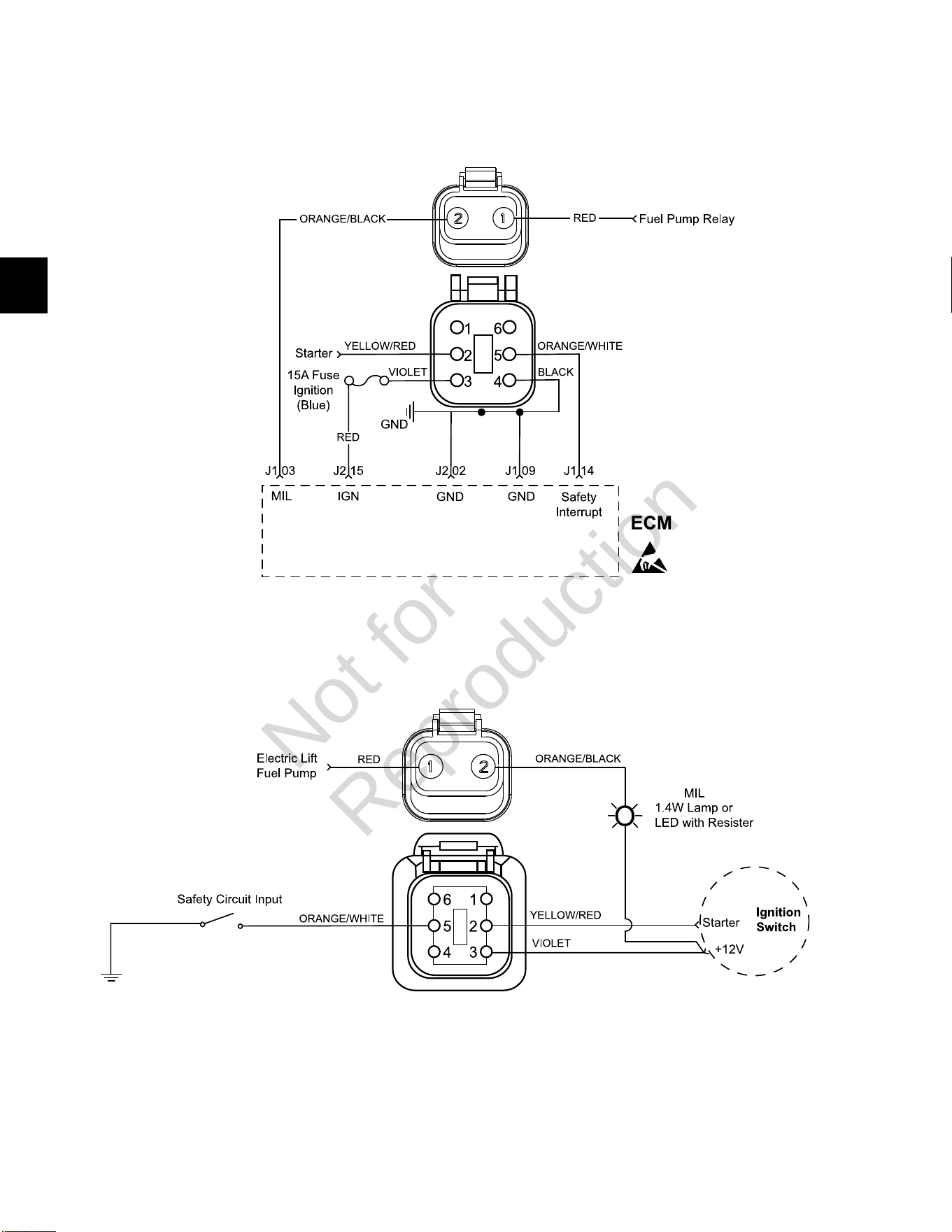
3
90
Model 610000 Marine Engine to Chassis 6-Place and 2-Place Connector Pin-Outs
Engine Connectors
Chassis Connectors (Equipment Side)
Not for
Reproduction
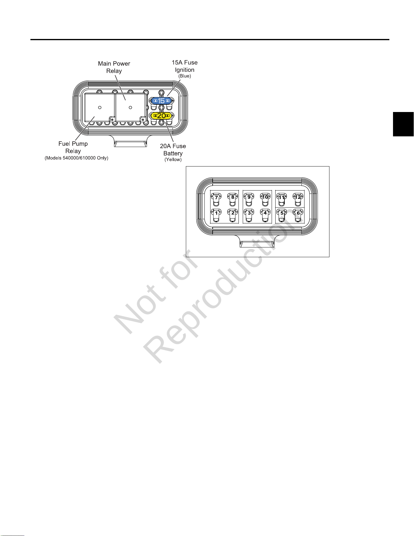
3
91
MODELS 490000/540000/610000 FUSE/RELAY BLOCK
Not for
Reproduction

3
92
Not for
Reproduction

4
93
SECTION 4 - SYMPTOMS
INTRODUCTION ----------------------------------------------------------------------------------------------------------------------------------- 94
ENGINE DOES NOT CRANK ------------------------------------------------------------------------------------------------------------------ 95
ENGINE CRANKS BUT DOES NOT START ---------------------------------------------------------------------------------------------- 96
ENGINE EXHIBITS HARD START SYMPTOMS ------------------------------------------------------------------------------------------98
ENGINE POWER OUTPUT LOW ------------------------------------------------------------------------------------------------------------100
ENGINE HUNTS ANDSURGES ------------------------------------------------------------------------------------------------------------- 102
ECM CONNECTOR SYMPTOMS ----------------------------------------------------------------------------------------------------------- 104
Not for
Reproduction

4
94
INTRODUCTION
Verify Customer Complaint
Verify customer complaint and then move to the
Diagnostic Table that best describes the problem.
• Engine does not crank.
• Engine cranks but does not start.
• Engine exhibits hard start symptoms.
• Engine power output low.
• Engine hunts and surges.
Perform Visual Check
Each Diagnostic Table contains an instruction to perform
a careful visual check. This check should always include
the following:
• Verify that ECM grounds and sensor connections are
clean, tight and in their proper location.
• Thoroughly check for any type of vacuum leak or
restriction.
• Look for air leaks at the throttle body mounting and
intake manifold sealing surfaces.
• Inspect ignition wires for cracks, hardness, improper
routing and carbon tracking.
• Inspect wires for kinks, cuts, burns, abraded
insulation, and other damage.
• Look for moisture in primary or secondary ignition
circuit connections.
• Look for salt corrosion on electrical connections and
exposed throttle body linkages.
Check electrical connectors for the following:
• Poor mating of connector halves, or a terminal not
fully seated in the connector body (backed out or
loose).
• Improperly formed or damaged terminals and/or
connectors.
• Improper contact tension of connector pin and socket
terminals in the problem circuit.
• Poor terminal to wire connection (both core and
insulation crimps).
Intermittents
IMPORTANT:Intermittents may not cause the MIL to
illuminate or set a DTC. DO NOT use the DTC Tables
to diagnose intermittent problems. The fault condition
must be present to locate the problem. Many intermittent
problems are caused by faulty electrical connections or
wiring.
The engine may be operated with a DVOM connected
to the suspect circuit. If an abnormal voltage is observed
when a malfunction occurs, it is a good indication that
there is a fault in the circuit.The Diagnostic Tool also may
be used to help detect intermittents.
Check DTC Memory Loss
Disconnect MAP sensor and idle engine until MIL is
illuminated. DTC P0107 should be set and stored in ECM
memory when the ignition is turned OFF. If it is not, then
the ECM is faulty. After performing this test, be sure to
clear the DTC from memory.
An intermittent MIL with no stored DTC may be caused by
one or more of the following conditions:
• Ignition coil is shorted to ground and arcing is present
at ignition wires or plugs.
• MIL wire to ECM is shorted to ground.
• Poor ECM grounds.
• An electrical system interference caused by a sharp
electrical surge. The problem normally occurs when
the faulty component is operated.
• Secondary ignition components are shorted to
ground, or there is an open in the ignition coil ground.
• Engine components, such as starters, alternators or
relays, are internally shorted to ground.
Not for
Reproduction
4
95
ENGINE DOES NOT CRANK
Step Action Yes No
1 Perform OBD System Check.
Are any DTCs found?
Go to applicable DTC Table. Go to step 2.
2 Perform a careful visual check.
Is a problem found?
Repair Go to step 3.
3 Check battery as follows:
• Look for loose or corroded terminals.
• Verify battery voltage is 12.2-13.5 volts.
Is a problem found?
Repair Go to step 4.
4 Verify PTO clutch is not engaged.
Is PTO clutch engaged?
Disengage PTO clutch. Go to step 5.
5 Verify safety interrupt is NOT active or faulty, if equipped.
Is a problem found?
Repair Go to step 6.
6 Verify ignition switch is working properly. See Section 2 of the Intek
V-Twin Cylinder OHV Repair Manual.
Is a problem found?
Repair Go to step 7.
7 Verify starter is operating properly. See Section 6 of the Intek V-
Twin Cylinder OHV Repair Manual.
Is a problem found?
Repair Go to step 8.
8 Review diagnostic procedures in this table. If all steps have been
completed and no problems have been found, proceed as follows:
• Repeat visual check.
• ReviewDiagnostic Tool/Code Reader data.
• Check all electrical connections within the suspect circuit and/
or system.
Is a problem found?
Repair Go to step 9.
9 Carefully review data underECM CONNECTOR SYMPTOMSin
this section.
Is a problem found?
Repair Contact engine
manufacturer.
Not for
Reproduction

4
96
ENGINE CRANKS BUT DOES NOT START
Step Action Yes No
1 Perform OBD System Check.
Are any DTCs found?
Go to applicable DTC Table. Go to step 2.
2 Perform a careful visual check.*
Is a problem found?
Repair Go to step 3.
3 Verify fuel in tank(s).
Is there insufficient fuel in tank(s)?
Add fuel. Go to step 4.
4 Check fuel shut off valve, if equipped.
Is fuel shut off valve closed?
Open fuel shut off valve. Go to step 5.
5 Check the following fuel system components for dirt, water, or
other contaminants.
• Fuel tanks
• Fuel filter
• Fuel lines
• Fuel pumps
Is a problem found?
Repair Go to step 6.
6 Verify that fuel pressure is 38-43 psi (262-296 kPa). SeeCHECK/
RELIEVE FUEL SYSTEM PRESSUREinSECTION 5 -
REMOVAL/INSTALLATION.
Is a problem found?
Repair Go to step 7.
7 Verify safety interrupt is NOT active or faulty, if equipped.
Is a problem found?
Repair Go to step 8.
8 Check battery as follows:
• Look for loose or corroded terminals.
• Verify battery voltage is 12.2-13.5 volts.
Is a problem found?
Repair Go to step 9.
9 Verify that each cylinder is getting spark. See Intek V-Twin Cylinder
OHV Repair Manual.
Is a problem found?
Repair Go to step 10.
10 SeeVERIFY ECM POWERS UPinSECTION 2 -
TROUBLESHOOTING DTCs.
Is a problem found?
Repair Go to step 11.
Continued...
*NOTE:Verify that the fuel pump primes for approximately two seconds when the ECM is powered up. If fuel pump
primes for only 1/2 second, then the Safety Circuit is the likely problem.
Not for
Reproduction

4
97
Step Action Yes No
11 Check engine for the following mechanical problems:
• Low compression.
• Leaking cylinder head gaskets.
• Proper valve set up.
See Intek V-Twin Cylinder OHV Repair Manual.
Is a problem found?
Repair Go to step 12.
12 Review diagnostic procedures in this table. If all steps have been
completed and no problems have been found, proceed as follows:
• Repeat visual check.
• ReviewDiagnostic Tool/Code Readerdata.
• Check all electrical connections within the suspect circuit and/
or system.
Is a problem found?
Repair Go to step 13.
13 Carefully review data underECM CONNECTOR SYMPTOMSin
this section.
Is a problem found?
Repair Contact engine
manufacturer.
Not for
Reproduction

4
98
ENGINE EXHIBITS HARD START SYMPTOMS
Definition:Engine cranks OK, but does not start for a long time. Engine does run, or may start but immediately die.
Step Action Yes No
1 Perform OBD System Check.
Are any DTCs found?
Go to applicable DTC Table. Go to step 2.
2 Perform a careful visual check.
Is a problem found?
Repair Go to step 3.
3 Check the following fuel system components for dirt, water, or
other contaminants.
• Fuel tanks
• Fuel filter
• Fuel lines
• Fuel pumps
Is a problem found?
Repair Go to step 4.
4 Verify that fuel pressure is 38-43 psi (262-296 kPa). SeeCHECK/
RELIEVE FUEL SYSTEM PRESSUREinSECTION 5 -
REMOVAL/INSTALLATION.
Is a problem found?
Repair Go to step 5.
5 Check battery as follows:
• Look for loose or corroded terminals.
• Verify battery voltage is 12.2-13.5 volts.
Is a problem found?
Repair Go to step 6.
6 Check for intermittent opens or shorts to ground in MAP sensor
circuit.
Is a problem found?
Repair Go to step 7.
7 Check for proper TPS operation, if equipped.
Verify that throttle linkage is not sticking, binding or worn causing
high TPS voltage.
Is a problem found?
Repair Go to step 8.
8 Check for proper IAC operation, if equipped.
Is a problem found?
Repair Go to step 9.
Continued...
Not for
Reproduction

4
99
Step Action Yes No
9 Check engine for the following mechanical problems:
• Low compression.
• Leaking cylinder head gaskets.
• Proper valve set up.
See Intek V-Twin Cylinder OHV Repair Manual.
Is a problem found?
Repair Go to step 10.
10 Review diagnostic procedures in this table. If all steps have been
completed and no problems have been found, proceed as follows:
• Repeat visual check.
• ReviewDiagnostic Tool/Code Readerdata.
• Check all electrical connections within the suspect circuit and/
or system.
Is a problem found?
Repair Go to step 11.
11 Carefully review data underECM CONNECTOR SYMPTOMSin
this section.
Is a problem found?
Repair Contact engine
manufacturer.
Not for
Reproduction

4
100
ENGINE POWER OUTPUT LOW
Step Action Yes No
1 Perform OBD System Check.
Are any DTCs found?
Go to applicable DTC Table. Go to step 2.
2 Perform a careful visual check.
Is a problem found?
Repair Go to step 3.
3 Check the following fuel system components for dirt, water, or
other contaminants.
• Fuel tanks
• Fuel filter
• Fuel lines
• Fuel pumps
Is a problem found?
Repair Go to step 4.
4 Verify that fuel pressure is 38-43 psi (262-296 kPa). SeeCHECK/
RELIEVE FUEL SYSTEM PRESSUREinSECTION 5 -
REMOVAL/INSTALLATION.
Is a problem found?
Repair Go to step 5.
5 Verify crankcase oil is at the correct level.
Is a problem found?
Add crankcase oil. Go to step 6.
6 Verify air filter element is clean and dry.
Is a problem found?
Replace air filter element. Go to step 7.
7 Verify engine is not supporting a greater load than intended for its
application? Check for the following:
• Damaged drive belt.
• For mowers, verify blades are not restricted by debris.
• Faulty pulley bearing(s).
Is a problem found?
Repair Go to step 8.
8 Verify spark plugs are:
• Gapped properly.
• Not gas fouled.
• Not excessively worn.
Is a problem found?
Repair Go to step 9.
9 Verify exhaust is not restricted.
Is a problem found?
Repair Go to step 10.
Continued...
Not for
Reproduction

4
101
Step Action Yes No
10 Check engine for the following mechanical problems:
• Low compression.
• Leaking cylinder head gaskets.
• Proper valve set up.
See Intek V-Twin Cylinder OHV Repair Manual.
Is a problem found?
Repair Go to step 11.
11 Review diagnostic procedures in this table. If all steps have been
completed and no problems have been found, proceed as follows:
• Repeat visual check.
• ReviewDiagnostic Tool/Code Readerdata.
• Check all electrical connections within the suspect circuit and/
or system.
Is a problem found?
Repair Go to step 12.
12 Carefully review data underECM CONNECTOR SYMPTOMSin
this section.
Is a problem found?
Repair Contact engine
manufacturer.
Not for
Reproduction

4
102
ENGINE HUNTS ANDSURGES
Step Action Yes No
1 Perform OBD System Check.
Are any DTCs found?
Go to applicable DTC Table. Go to step 2.
2 Perform a careful visual check.
Is a problem found?
Repair Go to step 3.
3 Check the following fuel system components for dirt, water, or
other contaminants.
• Fuel tanks
• Fuel filter
• Fuel lines
• Fuel pumps
Is a problem found?
Repair Go to step 4.
4 Verify that fuel pressure is 38-43 psi (262-296 kPa). SeeCHECK/
RELIEVE FUEL SYSTEM PRESSUREinSECTION 5 -
REMOVAL/INSTALLATION.
Is a problem found?
Repair Go to step 5.
5 Check battery as follows:
• Look for loose or corroded terminals.
• Verify battery voltage is 12.2-13.5 volts.
Is a problem found?
Repair Go to step 6.
6 Verify crankcase oil is at the correct level.
Is a problem found?
Add crankcase oil. Go to step 7.
7 Verify air filter element is clean and dry.
Is a problem found?
Replace air filter element. Go to step 8.
8 Verify governor is set up properly. See Section 4 of the Intek V-
Twin Cylinder OHV Repair Manual.
Is a problem found?
Repair Go to step 9.
9 Inspect governor link spring for damage or improper installation.
Is a problem found?
Repair Go to step 10.
10 Disconnect governor spring, and check for binding or uneven
resistance in the governor arm travel from stop to stop.
Is a problem found?
Repair Go to step 11.
11 Inspect governor spring and controls for damage or improper
installation.
Is a problem found?
Repair Go to step 12.
Continued...
Not for
Reproduction

4
103
Step Action Yes No
12 Review diagnostic procedures in this table. If all steps have been
completed and no problems have been found, proceed as follows:
• Repeat visual check.
• ReviewDiagnostic Tool/Code Readerdata.
• Check all electrical connections within the suspect circuit and/
or system.
Is a problem found?
Repair Go to step 13.
13 Carefully review data underECM CONNECTOR SYMPTOMSin
this section.
Is a problem found?
Repair Contact engine
manufacturer.
Not for
Reproduction
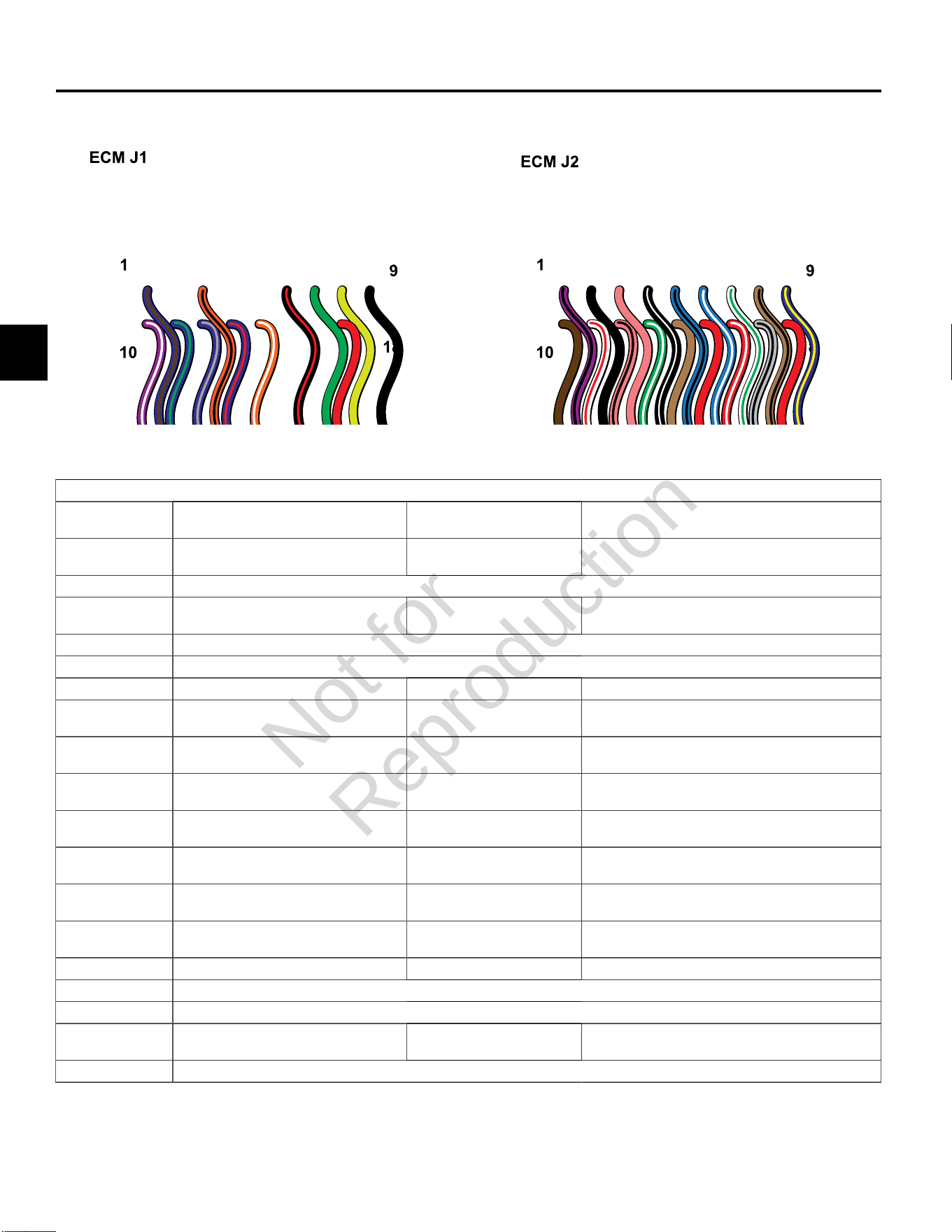
4
104
ECM CONNECTOR SYMPTOMS
ECM Connector J1 (Grey)
Connector-
Pin Number
Function Wire Color Possible Symptom(s) From Faulty Circuit
J1-01 IAC HIGH “A” *
Idle Air Control A High
Blue/Brown Rough, unstable, or incorrect idle
J1-02 NOT USED
J1-03 MIL
Malfunction Indicator Lamp
Orange/Black MIL inoperative
J1-04 NOT USED
J1-05 NOT USED
J1-06 Tachometer Black/Red Tachometer inoperative
J1-07 CAN Low
Used only for ECM Development
Green No Can Signal
J1-08 CAN High
Used only for ECM Development
Yellow No Can Signal
J1-09 GROUND
Power
Black An open ground or high resistance
ground may cause any or all symptoms
J1-10 IGN COIL CYL 2
Engine Spark Timing Coil Cylinder 2
Violet/White Rough idle, lack of power, stalling
J1-11 IAC LOW “A” *
Idle Air Control A Low
Blue/Green Rough, unstable, or incorrect idle
J1-12 IAC HIGH “B” *
Idle Air Control B High
Blue/Grey Rough, unstable, or incorrect idle
J1-13 IAC LOW “B” *
Idle Air Control B Low
Blue/Red Rough, unstable, or incorrect idle
J1-14 Safety Interrupt Circuit Orange/White No start
J1-15 NOT USED
J1-16 NOT USED
J1-17 MPR
Main Power Relay
Red An open B+ circuit or high resistance in the
B+ circuit may cause any or all symptoms
J1-18 NOT USED
* If Equipped
Not for
Reproduction
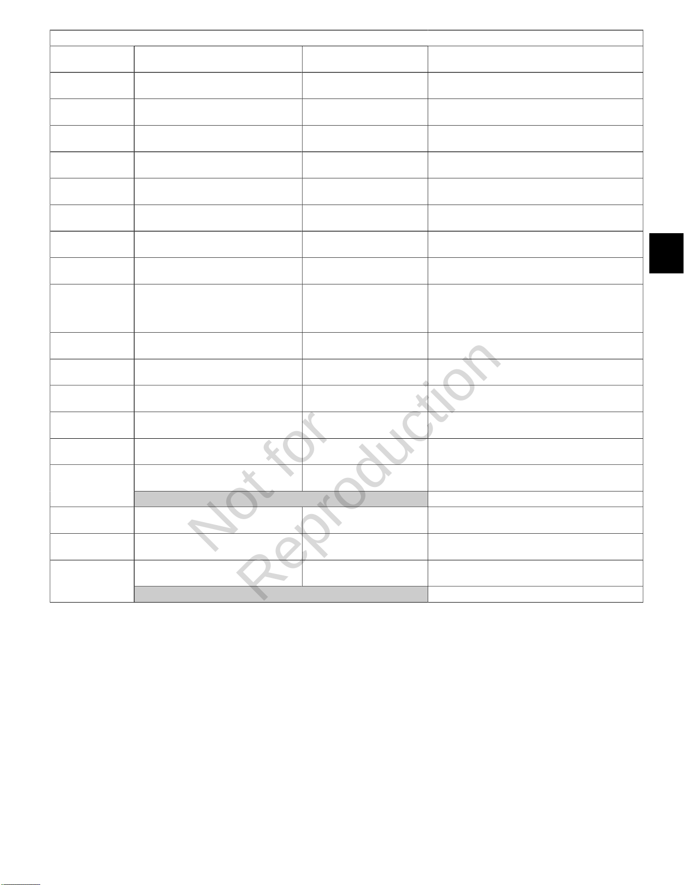
4
105
ECM Connector J2 (Black)
Connector-
Pin Number
Function Wire Color Possible Symptom(s) From Faulty Circuit
J2-01 IGN COIL CYL 1
Engine Spark Timing Coil Cylinder 1
Violet/Black Rough idle, lack of power, stalling
J2-02 GROUND
Power
Black An open ground or high resistance
ground may cause any or all symptoms
J2-03 K-LINE
Serial Data Diagnostic Communication
Pink No diagnostic data
J2-04 CKP High
23X
Black/White No start
J2-05 FUEL INJ CYL 1
Fuel Injector Cylinder 1
Lt.Blue/Black Rough idle, lack of power, stalling
J2-06 FUEL INJ CYL 2
Fuel Injector Cylinder 2
Lt. Blue/White Rough idle, lack of power, stalling
J2-07 HO2S HEATER CONTROL*
Oxygen Sensor Heater
White/Green Lack of power, surge, rough idle, exhaust odor
J2-08 MAT
Manifold Air Temperature Sensor
Tan/Black Rough idle
J2-09 HIGH PRESSURE FUEL
PUMP MODULE
Fuel Pump
Blue/Yellow No start
J2-10 5V RETURN
5 Volt Return
Brown Lack of performance, stalling, exhaust odor
J2-11 MAP
Manifold Absolute Pressure Sensor
White/Red Poor performance, surge, poor
fuel economy, exhaust odor
J2-12 TPS *
Throttle Position Sensor
Pink/Black Rough idle
J2-13 CKP Low
23X
Green/White No start
J2-14 EHT
Engine Head Temperature Sensor
Tan Poor performance, exhaust odor, rough idle
IGN
Ignition
Red No start, MIL inoperativeJ2-15
CAUTION:HOT AT KEY ON WHEN BATTERY CONNECTED !!!
J2-16 5V REFERENCE
5 Volt Reference
Red/White Lack of power, surge, rough idle, exhaust odor
J2-17 HO2S SIGNAL
Oxygen Sensor Signal
Grey/Black Lack of power, surge, rough idle, exhaust odor
VOLTAGE INPUT +12V
Voltage Battery
Red No startJ2-18
CAUTION:HOT AT ALL TIMES WHEN BATTERY CONNECTED !!!
* If Equipped
Not for
Reproduction

4
106
Not for
Reproduction

5
107
SECTION 5 - REMOVAL/INSTALLATION
CHECK/RELIEVE FUEL SYSTEM PRESSURE ----------------------------------------------------------------------------------------- 109
Safety Precautions --------------------------------------------------------------------------------------------------------------------------109
Check/Relieve Fuel System Pressure for Model 490000 ------------------------------------------------------------------------ 109
Check/Relieve Fuel System Pressure for Models 540000/610000 ------------------------------------------------------------ 109
MODEL 490000 FUEL SYSTEM COMPONENTS -------------------------------------------------------------------------------------- 113
Air Cleaner Assembly/Static Guard/Decorative Cover/Blower Housing -------------------------------------------------------113
ECM ---------------------------------------------------------------------------------------------------------------------------------------------114
MAP/MAT Sensor --------------------------------------------------------------------------------------------------------------------------- 115
Ignition Coil ----------------------------------------------------------------------------------------------------------------------------------- 115
Fuel Filter --------------------------------------------------------------------------------------------------------------------------------------115
Mechanical Diaphragm Fuel Pump -----------------------------------------------------------------------------------------------------115
Fuel Pump Module --------------------------------------------------------------------------------------------------------------------------116
Fuel Rail/Fuel Injectors -------------------------------------------------------------------------------------------------------------------- 116
CKP Sensor ---------------------------------------------------------------------------------------------------------------------------------- 117
EHT Sensor -----------------------------------------------------------------------------------------------------------------------------------118
EFI Wire Harness --------------------------------------------------------------------------------------------------------------------------- 118
HO2Sensor -----------------------------------------------------------------------------------------------------------------------------------121
MODELS 540000/610000 FUEL SYSTEM COMPONENTS --------------------------------------------------------------------------123
Access Cover/Blower Housing ---------------------------------------------------------------------------------------------------------- 123
ECM ---------------------------------------------------------------------------------------------------------------------------------------------123
MAP/MAT Sensor --------------------------------------------------------------------------------------------------------------------------- 124
Ignition Coil ----------------------------------------------------------------------------------------------------------------------------------- 124
Fuel Filter --------------------------------------------------------------------------------------------------------------------------------------124
Fuel Pump Module --------------------------------------------------------------------------------------------------------------------------125
Fuel Rail/Fuel Injectors -------------------------------------------------------------------------------------------------------------------- 125
CKP Sensor ---------------------------------------------------------------------------------------------------------------------------------- 126
Air Cleaner Assembly ---------------------------------------------------------------------------------------------------------------------- 126
Throttle Body --------------------------------------------------------------------------------------------------------------------------------- 127
EHT Sensor -----------------------------------------------------------------------------------------------------------------------------------128
EFI Wire Harness --------------------------------------------------------------------------------------------------------------------------- 128
IAC ---------------------------------------------------------------------------------------------------------------------------------------------- 129
TPS --------------------------------------------------------------------------------------------------------------------------------------------- 131
Non Adjustable TPS (Late Style) --------------------------------------------------------------------------------------------------131
Adjustable TPS (Early Style) ------------------------------------------------------------------------------------------------------- 131
HO2Sensor -----------------------------------------------------------------------------------------------------------------------------------132
Not for
Reproduction

5
108
MECHANICAL DIAPHRAGM FUEL PUMP FOR MODEL 490000 ------------------------------------------------------------------135
Volumetric Test ------------------------------------------------------------------------------------------------------------------------------ 135
ELECTRIC LIFT FUEL PUMP FOR MODELS 540000/610000 ----------------------------------------------------------------------137
Volumetric Test ------------------------------------------------------------------------------------------------------------------------------ 137
Not for
Reproduction
5
109
CHECK/RELIEVE FUEL SYSTEM PRESSURE
Safety Precautions
Always observe the following safety precautions before
removing any fuel system components.
WARNING
• Wear proper eye protection.
• Relieve fuel system pressure.
• Be sure there is no open flame or potential
ignition sources in the area.
• When removing a fuel hose or fitting, cover with a
shop towel to catch any fuel leakage.
• Collect any fuel and/or shop towels in approved
containers and dispose of properly.
• Exercise care to keep dirt and debris out of fuel
lines and fuel pump.
• Keep a dry chemical fire extinguisher on hand in
case of emergencies.
Check/Relieve Fuel System Pressure for
Model 490000
WARNING
The fuel in the fuel rail is under high pressure.
To avoid an uncontrolled discharge or spray of
fuel, and to reduce the risk of fire and personal
injury, always relieve fuel system pressure before
servicing.
Proceed as follows:
NOTE: Perform all steps if checking fuel system
pressure. If only relieving fuel system pressure, perform
steps 1-4 and 8-10.
1. Turn Ignition OFF.
2. Obtain Briggs & Stratton Fuel Pressure Gauge (Part
No. 19627).
3. Locate fuel pressure test port (Schrader valve) on fuel
pump module to fuel rail connector.
4. Remove protective cap from Schrader valve and
install fuel pressure gauge.
NOTE: A small amount of gasoline may drain from
the Schrader valve when the gauge is installed. Wrap
a shop towel around the valve fitting to catch any fuel
leakage.
5. Turn Ignition ON to pressurize fuel system.
6. Note the reading of the fuel pressure gauge. Fuel
pressure should remain steady at 38-43 psi (262-296
kPa).
7. Turn Ignition OFF.
8. Position the clear bleed tube in an approved
container and press the pressure relief button on
the gauge assembly to relieve fuel system pressure.
Fully depress and hold the pressure relief button until
pointer on the dial face is resting on the stop pin.
9. Remove fuel pressure gauge from Schrader valve.
NOTE: A small amount of gasoline may drain from
the Schrader valve when the gauge is removed. Wrap
a shop towel around the valve fitting to catch any fuel
leakage.
10. Install protective cap on Schrader valve.
Check/Relieve Fuel System Pressure for
Models 540000/610000
WARNING
The fuel in the fuel rail is under high pressure.
To avoid an uncontrolled discharge or spray of
fuel, and to reduce the risk of fire and personal
injury, always relieve fuel system pressure before
servicing.
Proceed as follows:
NOTE:Perform all steps if checking fuel system
pressure. If only relieving fuel system pressure, perform
steps 1-7.
1. Turn Ignition OFF.
2. Loosen fuel filler cap to relieve fuel tank pressure.
Tighten filler cap after loosening.
3. Remove access cover. SeeAccess Cover/Blower
Housing, Removal,steps 1-3.
4. Remove air cleaner assembly. SeeAir Cleaner
Assembly, Removal.
5. Pull out grey secondary lock and press to disconnect
fuel pump module connector.
6. Turn Ignition ON, Engine ON.
7. Start and run engine until it stalls. If it does not start,
crank engine a few times to relieve fuel system
pressure.
8. Obtain the following tools:
• Briggs & Stratton Fuel Pressure Gauge (Part No.
19627).
• Briggs & Stratton BIG BLOCK Fuel Pressure Test
Adapter (Part No. 19624).
Not for
Reproduction

5
110
9. Squeeze two tabs on quick disconnect fitting to
release fuel rail from fuel outlet port of fuel pump
module.
NOTE:Wrap shop towel around fitting to catch any
fuel leakage.
10. Install fuel pressure test adapter between fuel rail and
fuel pump module.
11. Remove protective cap from Schrader valve on fuel
pressure test adapter and install fuel pressure gauge.
12. Connect fuel pump module connector. Push in grey
secondary lock to secure.
13. Turn Ignition ON to pressurize fuel system.
14. Note the reading of the fuel pressure gauge. Fuel
pressure should remain steady at38-43 psi(262-296
kPa).
15. Turn Ignition OFF.
16. Position the clear bleed tube in an approved
container and press the pressure relief button on
the gauge assembly to relieve fuel system pressure.
Fully depress and hold the pressure relief button until
pointer on the dial face is resting on the stop pin.
17. Remove fuel pressure gauge from Schrader valve on
fuel pressure test adapter.
NOTE:A small amount of gasoline may drain from
the Schrader valve when the gauge is removed. Wrap
a shop towel around the valve fitting to catch any fuel
leakage.
18. Install protective cap on Schrader valve.
19. Remove fuel pressure test adapter between fuel rail
and fuel pump module.
20. Firmly push quick disconnect fitting on fuel rail onto
fuel outlet port of fuel pump module. Gently tug on
fitting to verify that it is properly seated and secure.
21. Turn ignition switch ON for two seconds, and then
OFF for 10 seconds. Turn the ignition switch back to
ON and check for fuel leaks.
22. Install air cleaner assembly. SeeAir Cleaner
Assembly, Installation.
23. Install access cover. SeeAccess Cover/Blower
Housing, Installation, steps 7-10.
Not for
Reproduction

5
111
This page is intentionally left blank.
Not for
Reproduction
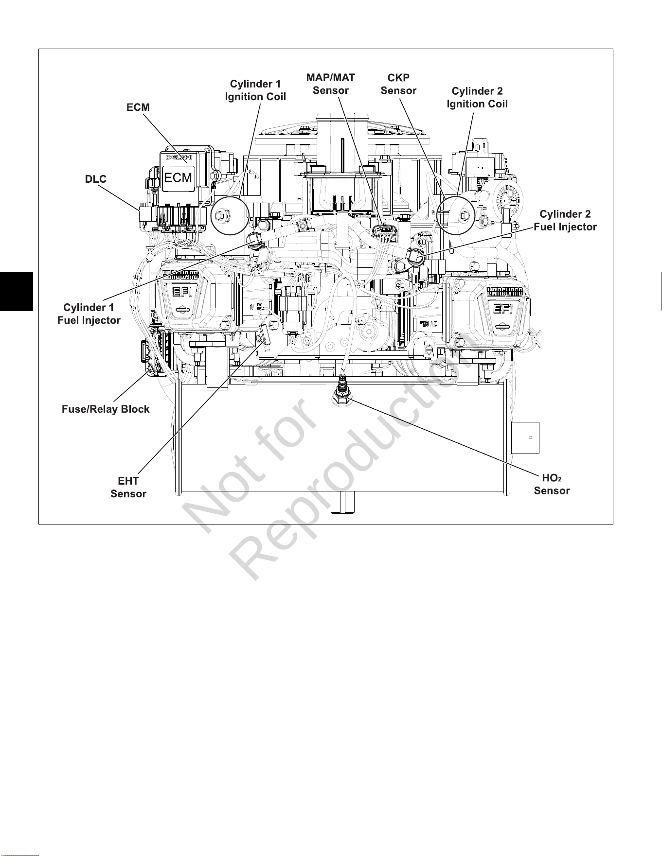
5
112
7
NOTE:Static guard, decorative cover, and blower housing removed for illustration purposes.
Not for
Reproduction
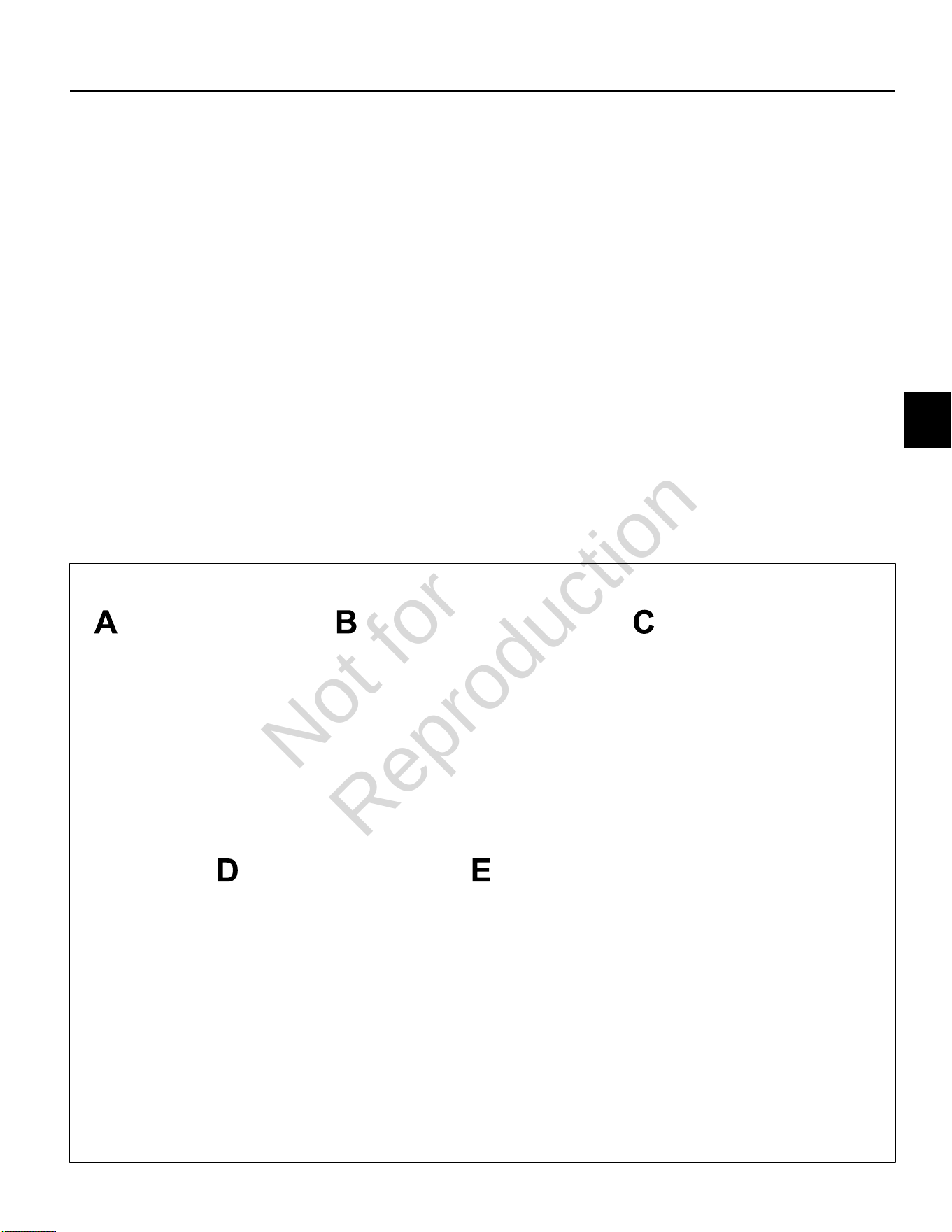
5
113
MODEL 490000 FUEL SYSTEM COMPONENTS
Air Cleaner Assembly/Static Guard/
Decorative Cover/Blower Housing
Removal
1. See Figure8. Remove air cleaner (A) as follows:
A. Rotate screw to loosen band clamp at air inlet
elbow end of air hose. Remove air hose from air
inlet elbow.
B. Remove two screws to release retaining strap
from upper air cleaner bracket.
C. Remove air cleaner with retaining strap.
2. Remove six hex flange screws to release static guard
(B).
3. Remove four hex flange screws to release decorative
cover (C) from upper air cleaner bracket.
4. Remove four hex flange screws to release fan guard
(D) from blower housing.
5. Remove two hex flange screws to release blower
housing (E) from upper air cleaner bracket.
6. Remove two hex flange screws to release ECM
bracket and ECM ground wire ring terminal from
blower housing.
7. Remove two hex flange screws to release mechanical
diaphragm fuel pump bracket from blower housing.
8. Remove four hex flange screws to release oil cooler
bracket from blower housing.
9. Disconnect ignition coil connectors.
10. Push ignition coil conduit and connectors through
openings to inboard side of blower housing.
11. Remove high tension leads from spark plug terminals.
12. Loosen four alignment screws at rear of blower
housing.
13. Loosen two alignment screws at front of blower
housing.
14. Raise blower housing to remove from engine.
8
Not for
Reproduction
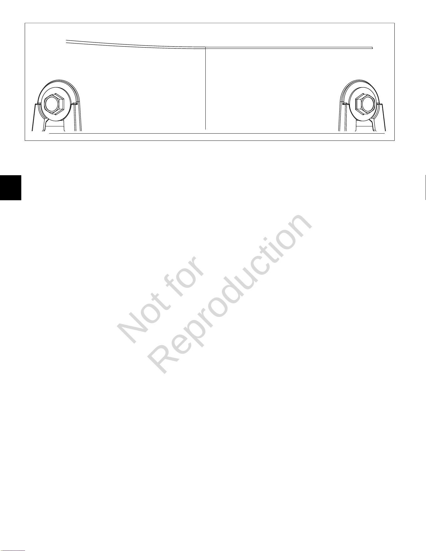
5
114
9
Installation
1. Push ignition coil connectors and conduit through
openings to outboard side of blower housing.
2. Hand start six blower housing alignment screws, if not
installed.
3. Place blower housing (E) into position on engine
aligning slots with six alignment screws.
4. Verify high tension leads are routed through slots on
each side or damage will occur when blower housing
is tightened.
5. Apply downward pressure to front of blower housing
and hand tighten front two alignment screws.
6. Apply downward pressure to rear of blower housing
and hand tighten the remaining four alignment
screws.
NOTE: To be sure that blower housing is properly
aligned, verify that washer head of each screw
appears as shown in Figure 9.
7. Alternately tighten six alignment screws to 75-95 lb-in
(9-11 Nm) using a crosswise pattern.
8. Install two hex flange screws to fasten blower housing
to upper air cleaner bracket. Alternately tighten
screws to 75-95lb-in (9-11 Nm).
9. Install high tension leads onto spark plug terminals.
10. Connect ignition coil connectors.
11. Install four hex flange screws to fasten oil cooler
bracket to blower housing. Alternately tighten screws
to 25-35lb-in (3-4 Nm) using a crosswise pattern.
12. Install two hex flange screws to fasten mechanical
diaphragm fuel pump bracket to blower housing.
Alternately tighten screws to 12-16lb-in (1-2 Nm).
13. Install two hex flange screws to fasten ECM bracket
and ECM ground wire ring terminal to blower housing.
Alternately tighten screws to 25-35lb-in (3-4 Nm).
14. Install four hex flange screws to fasten fan guard
(D) to blower housing. Alternately tighten screws to
40-48lb-in (5 Nm) using a crosswise pattern.
15. Install four hex flange screws to fasten decorative
cover (C) to upper air cleaner bracket. Alternately
tighten screws to 50-70lb-in (6-8 Nm) using a
crosswise pattern.
16. See Figure 8. Install six hex flange screws to fasten
static guard (B) to blower housing. Alternately tighten
screws to 25-35lb-in (3-4 Nm) using a crosswise
pattern.
17. Install air cleaner (A) as follows:
A. Place air cleaner on upper air cleaner bracket.
B. Install two screws to fasten retaining strap to
upper air cleaner bracket. Alternately tighten
screws to 75-95lb-in (9-11 Nm).
C. Position band clamp on free end of air hose.
D. Install air hose onto air inlet elbow and tighten
band clamp screw to 10-20lb-in (1-2 Nm).
ECM
Removal
1. Remove two hex flange screws to release ECM
bracket from blower housing.
2. Disconnect J1 and J2 connectors from ECM.
Installation
1. Connect J1 and J2 connectors to new ECM.
NOTE: The words BLACK and GREY are molded into
the ECM housing to ensure proper installation of J1
(Grey) and J2 (Black) connectors.
2. Slide hex flange screw through inside ECM bracket
flange and ground wire ring terminal. Start screw into
inside boss on blower housing.
3. Install second Phillips screw on opposite side, and
alternately tighten screws to 25-35lb-in (3-4 Nm).
Not for
Reproduction
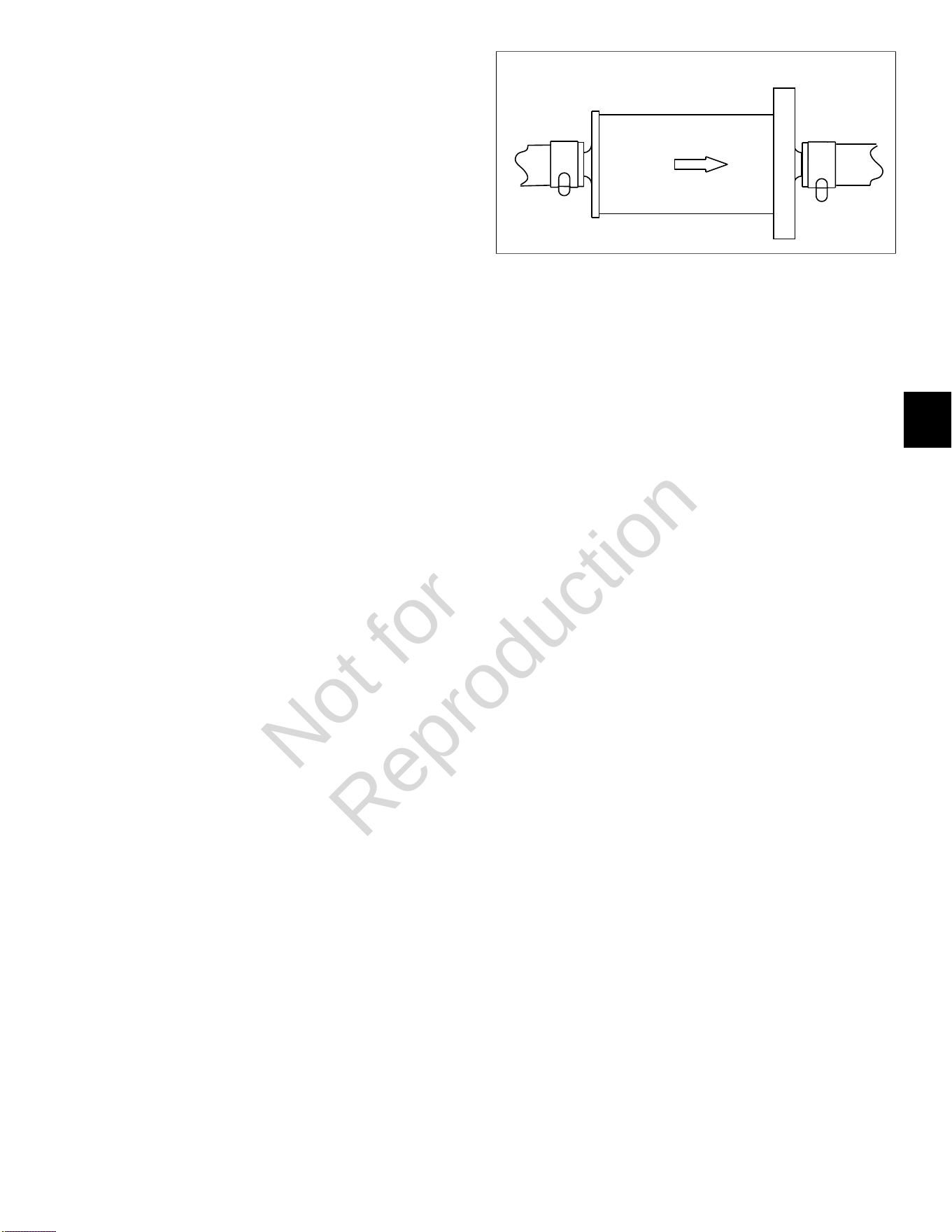
5
115
MAP/MAT Sensor
Removal
1. Remove air cleaner assembly, static guard and
decorative cover. SeeAir Cleaner Assembly/Static
Guard/Decorative Cover/ Blower Housing, Removal,
steps 1-3.
2. Pull out red secondary lock and press latch to
disconnect MAP/MAT sensor connector.
3. Remove screw to release sensor bracket from
threaded boss on intake manifold.
4. Remove sensor from intake manifold.
Installation
1. Lightly lubricate O-ring of new sensor.
2. Install sensor into intake manifold.
3. Install screw to fasten sensor bracket to threaded
boss on intake manifold. Tighten screw to 50-60lb-in
(6-7 Nm).
4. Connect MAP/MAT sensor connector. Push in red
secondary lock to secure.
5. Install decorative cover, static guard, and air cleaner
assembly. See Air Cleaner Assembly/Static Guard/
Decorative Cover/Blower Housing, Installation, steps
15-17.
Ignition Coil
Removal
1. SeeAir Cleaner Assembly/Static Guard/Decorative
Cover/Blower Housing, Removal.
2. Remove two hex flange screws to release ignition coil
from blower housing.
Installation
1. Install two hex flange screws to fasten new ignition
coil to blower housing. Alternately tighten screws to
20-35lb-in (3-4 Nm).
2. See Air Cleaner Assembly/Static Guard/Decorative
Cover/Blower Housing, Installation.
Fuel Filter
Removal
1. Relieve fuel system pressure. SeeCHECK/RELIEVE
FUEL SYSTEM PRESSUREin this section.
2. Squeeze hose clip and remove fuel inlet hose from
fuel filter fitting.
NOTE:Wrap shop towel around fuel filter fittings to
catch any fuel leakage.
10
3. Squeeze hose clip and remove fuel outlet hose from
fuel filter fitting.
Installation
1. See Figure10. With the arrow pointing in the direction
of fuel flow, installnewfuel filter between fuel inlet
and outlet hoses.
2. Turn ignition switch ON for two seconds, and then
OFF for 10 seconds. Turn the ignition switch back to
ON and check for fuel leaks.
Mechanical Diaphragm Fuel Pump
Removal
1. See Figure11. Squeeze hose clip at fuel inlet port (A)
and remove hose from fuel filter.
NOTE:Wrap shop towel around fittings to catch any
fuel leakage.
2. Squeeze hose clip at fuel outlet port (B) and remove
hose to fuel pump module.
3. Gently pull crankcase vacuum hose from pulse line
fitting (C).
4. Remove two hex flange screws to release fuel pump
from blower housing.
Installation
1. Orient new fuel pump with the crankcase vacuum
and fuel inlet ports pointing down.
2. Install two hex flange screws to secure fuel pump
to blower housing. Alternately tighten screws to
12-16lb-in (1-2 Nm).
3. Squeeze hose clip and install hose from fuel filter
onto fuel inlet port (A).
4. Squeeze hose clip and install hose to fuel pump
module onto fuel outlet port (B).
5. Gently push crankcase vacuum hose onto pulse
line fitting (C). Be sure hose is not twisted after
installation.
6. Turn ignition switch ON for two seconds, and then
OFF for 10 seconds. Turn the ignition switch back to
ON and check for fuel leaks.
Not for
Reproduction
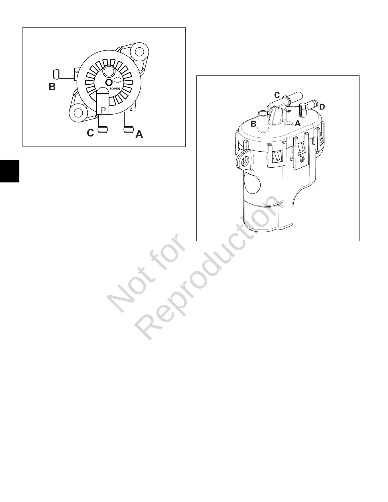
5
116
11
Fuel Pump Module
Removal
1. Relieve fuel system pressure. SeeCHECK/RELIEVE
FUEL SYSTEM PRESSUREin this section.
2. See Figure12. Squeeze clip and remove EVAP tube
(to elbow fitting on cylinder 2 heat shield) from top of
fuel pump module (A).
3. Remove three hex screws to release fuel pump
module from bracket.
4. Pull out grey secondary lock and press latch to
disconnect fuel pump module connector (B).
5. Squeeze two tabs on quick disconnect fitting to
release fuel rail from fuel outlet port (C).
NOTE:Wrap shop towel around fittings to catch any
fuel leakage.
6. Squeeze clip at fuel inlet port (D) and remove hose
from mechanical diaphragm fuel pump.
NOTE:Fuel pump module may contain a small
quantity of fuel. Hold fuel pump module with inlet and
outlet fittings pointing upward until fuel can be drained
into a suitable container.
Installation
1. Squeeze clip and install hose from mechanical
diaphragm fuel pump onto fuel inlet port (D).
2. Firmly push quick disconnect fitting on fuel rail onto
fuel outlet port (C). Gently tug on fitting to verify that it
is properly seated and secure.
3. Connect fuel pump module connector (B). Push in
grey secondary lock to secure.
4. Squeeze clip and install EVAP tube (to elbow fitting
on cylinder 2 heat shield) at top of fuel pump module
(A).
5. Install three hex screws to fasten fuel pump module
to bracket. Alternately tighten screws to 60-70lb-in
(7-8 Nm).
6. Turn ignition switch ON for two seconds, and then
OFF for 10 seconds. Turn the ignition switch back to
ON and check for fuel leaks.
12
Fuel Rail/Fuel Injectors
Removal
1. Relieve fuel system pressure. SeeCHECK/RELIEVE
FUEL SYSTEM PRESSUREin this section.
2. SeeAir Cleaner Assembly/Static Guard/Decorative
Cover/Blower Housing, Removal.
3. Remove EFI wire harness retaining clip from fuel rail.
See A of Figure13.
4. Remove fuel rail retaining clip from hole in CKP
sensor bracket. Remove fuel rail retaining clip from
fuel rail. See B of Figure13.
5. Pull out green secondary lock and press tab to
disconnect fuel injector connectors.
6. Remove two hex flange screws to release fuel
injector cap flanges from intake manifold.
7. Remove retaining clips to release fuel injector caps
from fuel injectors. Note orientation of the retaining
clips prior to removal.
8. Remove fuel injectors from intake manifold.
9. Squeeze two tabs on quick disconnect fitting to
release fuel rail from fuel pump module.
NOTE:Wrap shop towel around fitting to catch any
fuel leakage.
Not for
Reproduction
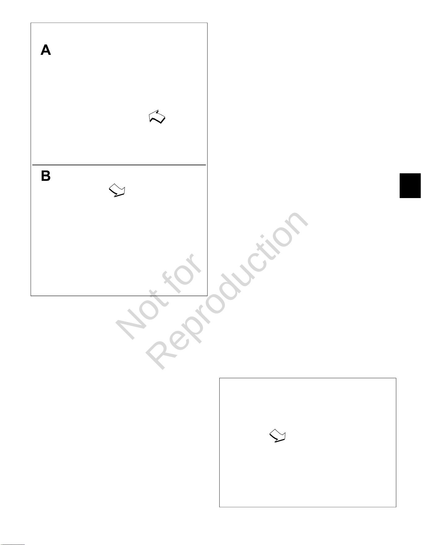
5
117
13
Installation
1. Lightly lubricate fuel injector O-rings with clean
engine oil.
2. Install fuel injectors into intake manifold.
3. Install retaining clips to secure fuel injector caps to
fuel injectors. Orient retaining clips as noted during
removal. Be sure retaining clips are fully engaged.
4. Install two hex flange screws to fasten fuel injector
cap flanges to intake manifold. Tighten screws to
50-60lb-in (6-7 Nm).
5. Connect fuel injector connectors. Push in green
secondary locks to secure.
6. Install EFI wire harness retaining clip onto fuel rail.
7. Install fuel rail retaining clip onto fuel rail. Install fuel
rail retaining clip into hole in CKP sensor bracket.
8. Route quick disconnect fitting on fuel rail through
opening in cylinder 2 heat shield to fuel pump
module.
9. Firmly push quick disconnect fitting onto fuel pump
module. Gently tug on fitting to verify that it is properly
seated and secure.
10. Turn ignition switch ON for two seconds, and then
OFF for 10 seconds. Turn the ignition switch back to
ON and check for fuel leaks.
11. See Air Cleaner Assembly/Static Guard/Decorative
Cover/Blower Housing, Installation.
CKP Sensor
Removal
1. SeeAir Cleaner Assembly/Static Guard/Decorative
Cover/Blower Housing, Removal.
2. Remove fuel rail retaining clip from hole in CKP
sensor bracket.
3. Remove two hex flange screws to release CKP
sensor bracket from cylinder mounting bosses.
4. Disconnect CKP sensor connector.
Installation
1. Start two hex flange screws to fasten CKP sensor
bracket to cylinder mounting bosses. Alternately
tighten screws until snug.
2. On side opposite connector, install mounting plate in
groove of CKP sensor housing.
3. Insert CKP sensor into bracket. Align hole in
mounting plate with hole stamped “49” on bracket.
Install TORX screw and tighten to 25-35lb-in (3-4
Nm).
4. Loosen two bracket screws and adjust as necessary
until gap between CKP sensor and flywheel tooth is
0.010 inches (0.254 mm). See Figure 14.
5. Alternately tighten CKP sensor bracket screws to
20-30lb-in (2-3 Nm).
6. Connect CKP sensor connector.
14
Not for
Reproduction
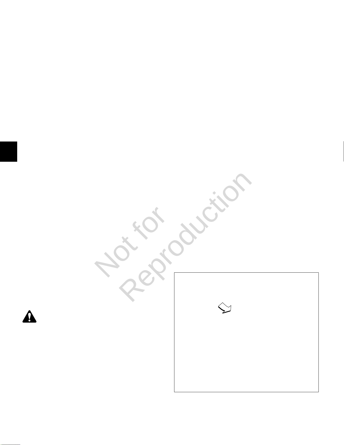
5
118
7. Install fuel rail retaining clip into hole in CKP sensor
bracket.
8. See Air Cleaner Assembly/Static Guard/ Decorative
Cover/Blower Housing, Installation.
EHT Sensor
NOTE:The EHT sensor is an integral part of the EFI wire
harness and is not sold separately. Replace EFI wire
harness if EHT sensor is bad.
EFI Wire Harness
Removal
1. SeeAir Cleaner Assembly/Static Guard/Decorative
Cover/Blower Housing, Removal.
2. Remove flywheel. Proceed as follows:
A. Using an air impact wrench or breaker bar,
loosen flywheel nut.
B. Remove four hex flange screws to release fan
from flywheel.
C. Unthread flywheel nut from crankshaft taper and
then thread back on a couple turns.
D. Obtain flywheel puller (Part No. 19621).
E. Using the larger holes in the puller tool, and with
the open side facing upward, place tool over
crankshaft taper seating it on the flywheel nut.
F. Install hex nut on each of two puller screws.
Insert puller screws through holes in puller tool,
and then thread into flywheel an equal number of
turns.
G. Rotate hex nuts until contact is made with the
puller tool. Verify that the puller tool is square.
See Figure15.
H. Holding screws to prevent rotation, alternately
turn each hex nut in small increments until the
flywheel is free.
I. Remove flywheel from crankshaft.
CAUTION
Keep fingers away from inside edge of flywheel
during removal. Stator magnets are powerful and
may pull the flywheel in with sufficient force to
cause hand injury.
J. Remove screws to release puller tool from
flywheel.
3. Remove four TORX screws to release backplate (and
oil fill tube flange) from cylinder mounting bosses.
4. See A of Figure16. Proceed as follows:
• Disconnect 6-place (or 8-place) engine to chassis
connector.
• Disconnect starter solenoid ring and spade
terminals.
• Remove hex flange screw to release ground wire
ring terminal from cylinder boss.
• Remove two hex flange screws to release starter
motor from cylinder 1.
• Disconnect voltage regulator connector.
• Remove hex flange screw to release fuse/relay
block cover and voltage regulator bottom flange
from cylinder 1 heat shield.
• Disconnect ECM J1 and J2 connectors.
• Disconnect ECM ground wire ring terminal.
5. See B of Figure16. Proceed as follows:
• Remove TORX screw to release EHT sensor
bracket from cylinder 1.
NOTE:Ignition coil connectors are disconnected
during blower housing removal.
• Disconnect fuel injector connectors.
• Disconnect HO2 sensor connector.
• Disconnect MAP/MAT sensor connector.
• Remove EFI wire harness from retaining clip on
fuel rail (centered at front of intake elbow).
• Cut cable strap to release EFI wire harness from
intake manifold.
6. See C of Figure16. Proceed as follows:
• Disconnect CKP sensor connector.
• Disconnect fuel pump module connector.
• Disconnect oil pressure switch connector.
Release wire from hose clip on cylinder 2 heat
shield.
7. Remove EFI wire harness from engine.
15
Not for
Reproduction
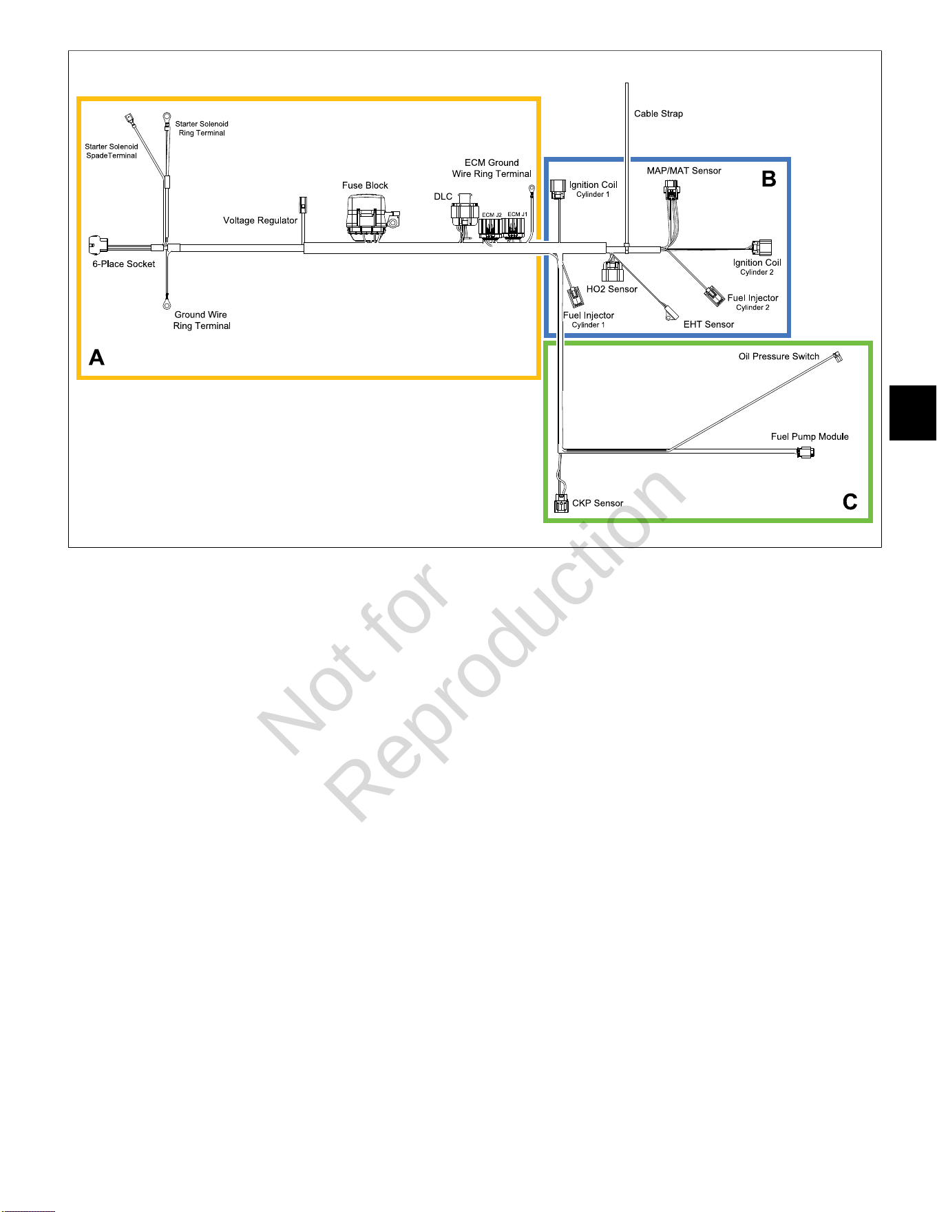
5
119
16
Installation
1. Position new EFI wire harness on engine separating
conduit and connectors into three groups as shown in
Figure 16. Proceed as follows:
A. Adjust wire harness as necessary, so that
ignition coil, MAP/MAT sensor, and fuel injector
connectors and conduit are positioned below the
fuel rail.
B. Draw out harness until ECM J1 and J2
connectors are seated at top of cylinder 1 valve
cover and fuse/relay block is next to voltage
regulator.
C. Draw out harness, so that 6-place (or 8-place)
engine to chassis connector, starter solenoid
ring and spade terminals, and ground wire ring
terminal run under cylinder 1 heat shield to area
of starter motor and oil fill tube.
D. Feed CKP sensor, fuel pump module, and
oil pressure switch connectors and conduit
under intake manifold (at point of cylinder 1 fuel
injector), and then up between fuel rail and air
intake elbow to outboard side of CKP sensor
bracket.
E. Route fuel pump module and oil pressure switch
connectors and conduit through opening at back
of cylinder 2 heat shield to area of fuel pump
module.
2. See C of Figure 16. Proceed as follows:
• Connect CKP sensor connector.
• Connect fuel pump module connector. Push in
grey secondary lock to secure.
• Route oil pressure switch sensor wire behind
fuel pump module bracket, and then capture in
hose clip on cylinder 2 heat shield. See Figure
17. Connect electrical connector to oil pressure
switch installed in oil filter mount.
3. See B of Figure 16. Proceed as follows:
• Install EFI wire harness into retaining clip on fuel
rail (centered at front of intake elbow).
• Connect MAP/MAT sensor connector. Push in
red secondary lock to secure.
• Connect fuel injector connectors. Push in green
secondary locks to secure.
• Connect HO2 sensor connector.
• Install cable strap to secure EFI wire harness to
intake manifold.
NOTE: Ignition coil connectors are connected
during blower housing installation.
• Orient EHT sensor with end rotated against tab
on cylinder 1. Install TORX screw and tighten to
20-40lb-in (2-5 Nm).
Not for
Reproduction
5
120
17
18
4. See A of Figure 16. Proceed as follows:
• Connect ECM J1 and J2 connectors.
NOTE: ECM ground wire ring terminal is
connected during blower housing installation.
• Install hex flange screw to fasten fuse/relay block
cover and voltage regulator bottom flange to
cylinder 1 heat shield. Tighten screw to 40-50lb-
in (5-6 Nm).
• Connect voltage regulator connector.
• Keeping 6-place (or 8-place) engine to chassis
connector, starter solenoid ring and spade
terminals, and ground wire ring terminal on
inboard side, install two hex flange screws to
fasten starter motor to cylinder 1.
• Seat starter motor by alternately tightening
screws to 50lb-in (6 Nm), and then final tighten
screws to 145-165lb-in (16-19 Nm).
NOTE: Exercise care to avoid pinching, kinking
or otherwise damaging wires as starter motor is
installed.
• Keeping 6-place (or 8-place) engine to chassis
connector, starter solenoid ring and spade
terminals, and ground wire ring terminal on
inboard side of oil fill tube, install four TORX
screws to fasten backplate (and oil fill tube
flange) to cylinder mounting bosses.
• Alternately tighten backplate screws to 90-110lb-
in (10-12 Nm) using a crosswise pattern.
NOTE: Exercise care to avoid pinching, kinking or
otherwise damaging wires as backplate and oil fill
tube is installed.
• Connect starter solenoid ring and spade
terminals.
• Install hex flange screw to fasten ground wire
ring terminal to cylinder boss. Tighten screw to
22-35lb-in (3-4 Nm). See Figure 18.
• Connect 6-place (or 8-place) engine to chassis
connector.
5. Install flywheel. Proceed as follows:
CAUTION
Keep fingers away from inside edge of flywheel
during installation. Stator magnets are powerful
and may pull the flywheel in with sufficient force to
cause hand injury.
A. Install flywheel onto crankshaft taper aligning
crankshaft and flywheel keyways. Install key.
B. Install flywheel washer onto crankshaft taper with
the dome side up.
C. Install flywheel nut onto crankshaft taper and
tighten to 120-140lb-ft (163-190 Nm).
D. Install four hex flange screws to fasten fan to
flywheel. Alternately tighten screws to 75-95lb-in
(9-11 Nm).
6. See Air Cleaner Assembly/Static Guard/Decorative
Cover/Blower Housing, Installation.
Not for
Reproduction

5
121
HO
2
Sensor
Removal
1. Disconnect HO
2
sensor connector.
2. Rotate sensor body hex counter-clockwise to release
sensor from muffler. See Figure19.
Installation
1. Rotate sensor body hex clockwise to secure sensor
to muffler. Tighten to 146-173lb-in (16-19 Nm).
2. Routing sensor cable conduit inboard of EFI wire
harness, connect HO
2
sensor connector.
19
Not for
Reproduction
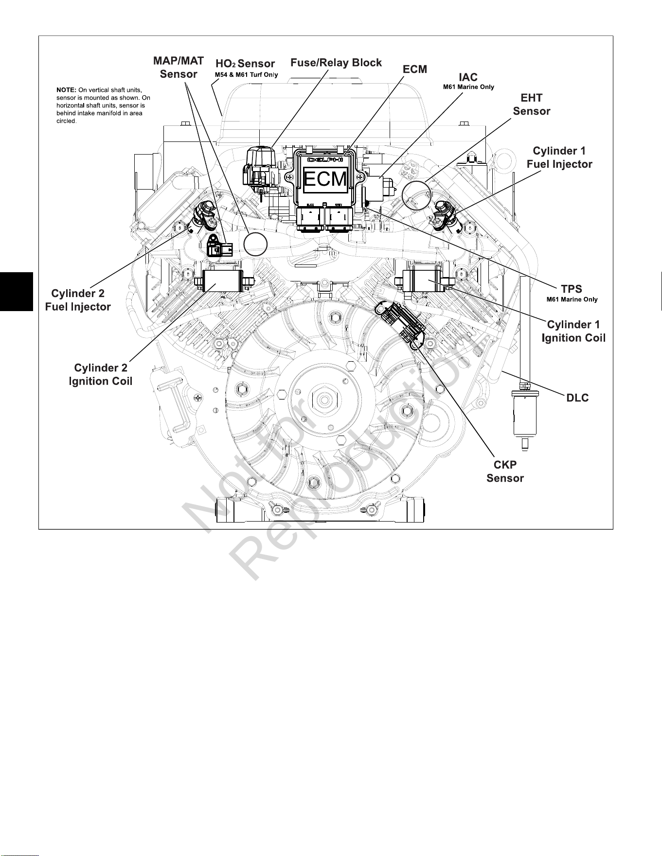
5
122
20
NOTE:Access cover and blower housing removed for illustration purposes.
Not for
Reproduction
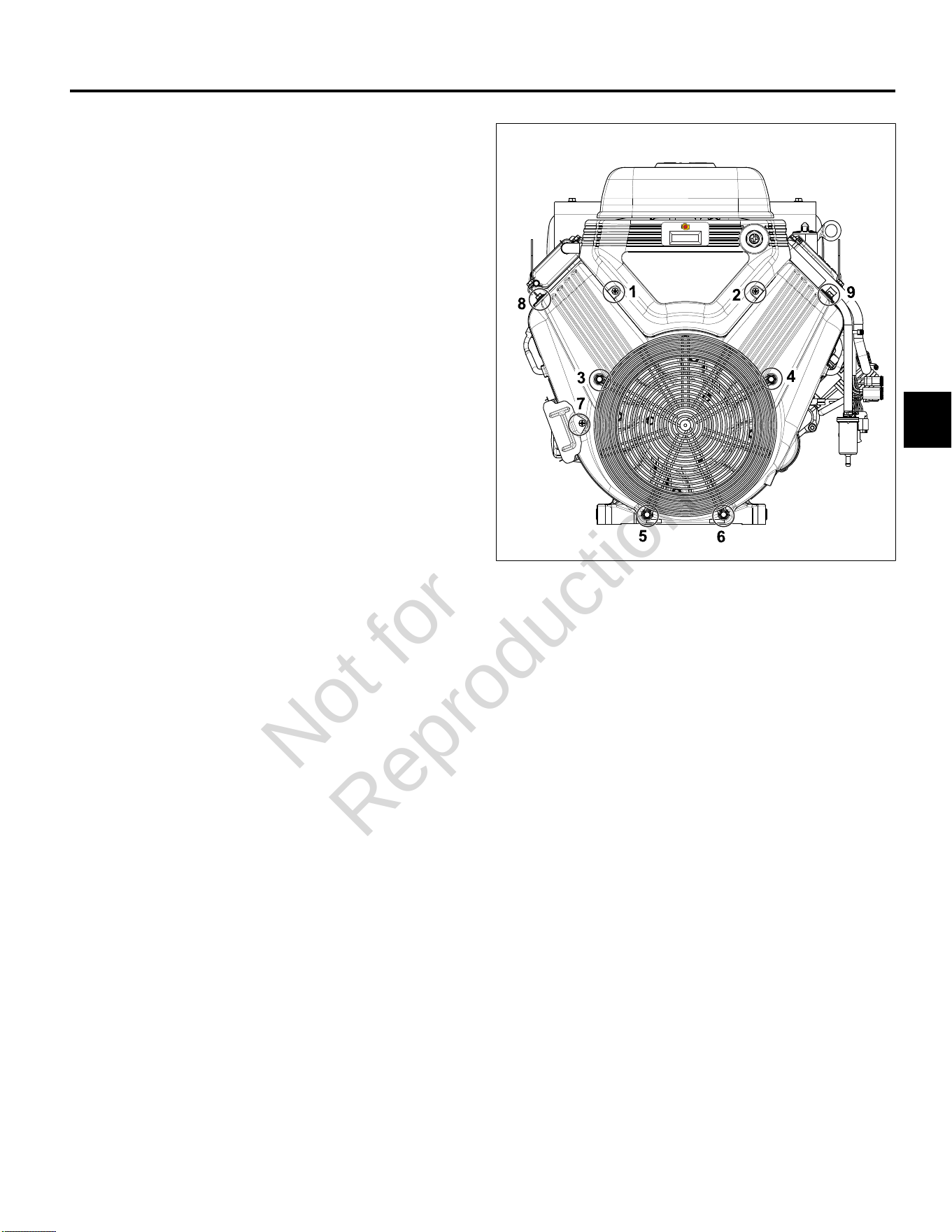
5
123
MODELS 540000/610000 FUEL SYSTEM COMPONENTS
Access Cover/Blower Housing
Removal
1. See Figure21. Remove two Phillips screws (1-2) to
release access cover from blower housing.
2. Lift access cover straight up to release tongues from
grooves in blower housing.
3. If equipped, disconnect tachometer/hourmeter/MIL
connector at back of access cover.
4. Remove four hex flange screws (3-6) from coupling
nuts to release wire guard.
5. Remove hex flange screw (7) to release oil cooler
bracket from blower housing.
6. Remove hex flange screws (8-9) to release left and
right side air guides and blower housing from intake
manifold.
7. Remove four coupling nuts (3-6). Lift blower housing
straight up to disengage from posts.
Installation
1. Place blower housing into position engaging holes
with four posts.
2. Verify high tension leads are routed through slots on
each side or damage will occur when blower housing
is tightened.
3. Install coupling nuts on posts (3-6). Alternately
tighten coupling nuts to 78-96 lb-in (9-11 Nm) using a
crosswise pattern.
4. Install two hex flange screws (8-9) to fasten left and
right side air guides and blower housing to intake
manifold. Tighten screws to 78-96lb-in (9-11 Nm).
5. Install hex flange screw (7) to fasten oil cooler bracket
to blower housing. Tighten screw to 35-43lb-in (4-5
Nm).
6. Install four hex flange screws (3-6) to fasten wire
guard to coupling nuts. Tighten screws to 78-96lb-in
(9-11 Nm).
7. If equipped, connect tachometer/hourmeter/ MIL
connector at back of access cover.
8. Lower access cover straight down to engage tongues
in grooves of blower housing.
9. Verify IAC connector wire harness conduit is routed
through groove or damage will occur when access
cover is tightened.
10. Install two Phillips screws (1-2) to fasten access
cover to blower housing. Tighten screws to 35-43lb-
in (4-5 Nm).
21
ECM
NOTE:A product improvement to dampen vibration to
the ECM/fuse block bracket was recently introduced in
production. A Briggs & Stratton Service Kit (Part No.
847337) to upgrade product in the field includes a new
fuse/relay block cover, ECM mounting bracket, rubber
isolation mounts, and mounting hardware. See Service
Bulletin DSB-1053 for details.
Removal
1. Remove access cover. SeeAccess Cover/Blower
Housing, Removal,steps 1-3.
2. Remove two Phillips screws to release ECM from
ECM/fuse block bracket.
3. Disconnect J1 and J2 connectors from ECM.
Installation
1. Connect J1 and J2 connectors to new ECM.
NOTE: The words BLACK and GREY are molded into
the ECM housing to ensure proper installation of J1
(Grey) and J2 (Black) connectors.
2. Slide Phillips screw through ECM flange (Grey ECM
J1 connector side) and ground wire ring terminal.
Start screw into ECM/ fuse block bracket.
Not for
Reproduction
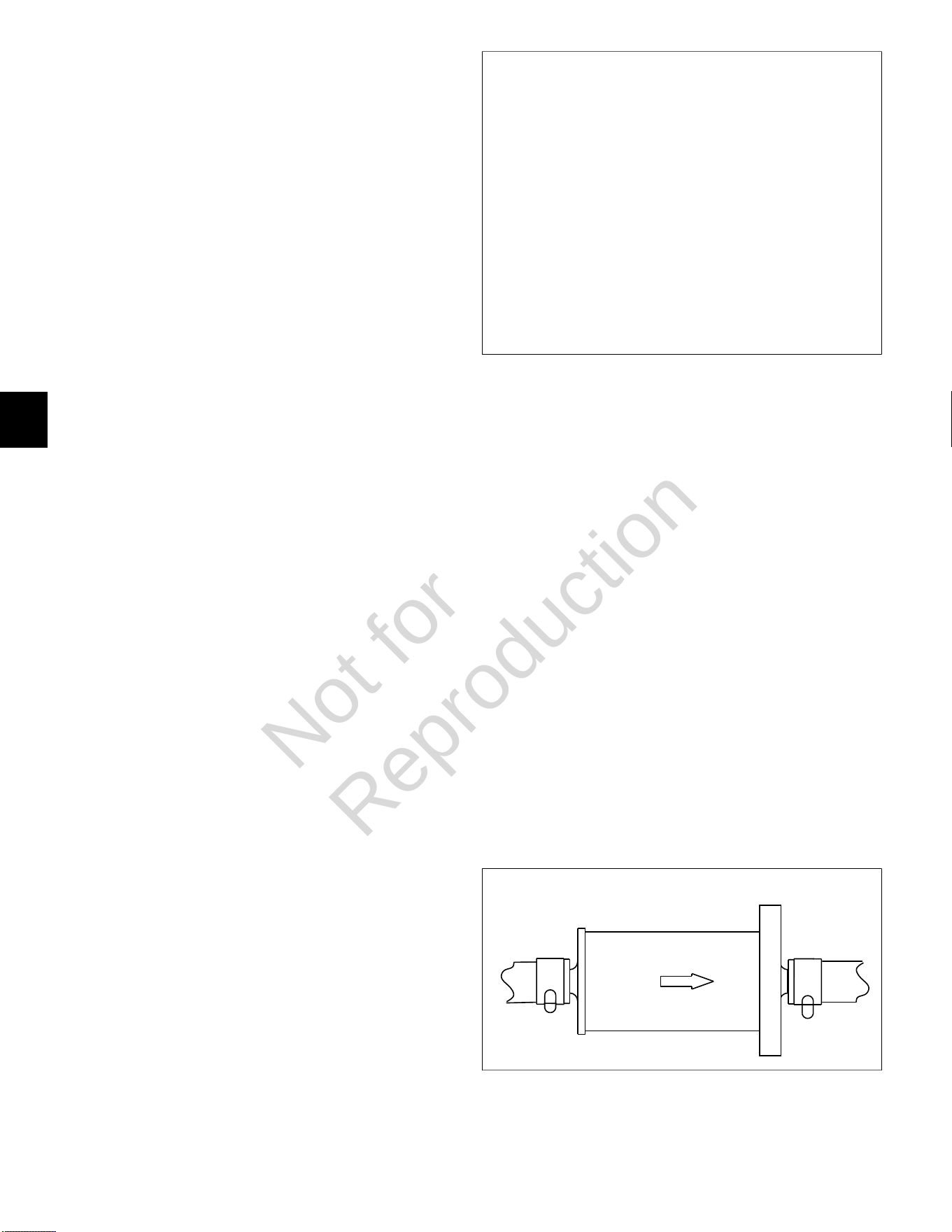
5
124
3. Install second Phillips screw on opposite side, and
alternately tighten screws to 35-52lb-in (4-6 Nm).
4. Install access cover. See Access Cover/Blower
Housing, Installation, steps 7-10.
MAP/MAT Sensor
Removal
1. SeeAccess Cover/Blower Housing, Removal.
2. Pull out red secondary lock and press latch to
disconnect MAP/MAT sensor connector.
3. Remove hex flange screw to release sensor flange
from intake manifold.
4. Remove sensor from intake manifold.
Installation
1. Lightly lubricate O-ring of new MAP/MAT sensor.
2. Install sensor into intake manifold aligning hole in
flange with hole in intake manifold.
3. Install hex flange screw and tighten to 78- 96lb-in
(9-11 Nm).
4. Connect MAP/MAT sensor connector. Push in red
secondary lock to secure.
5. See Access Cover/Blower Housing, Installation.
Ignition Coil
Removal
1. SeeAccess Cover/Blower Housing, Removal.
2. See Figure22. Remove two hex flange screws to
release ignition coil from intake manifold mounting
bosses.
NOTE:Do not cut cable strap on inside mounting
boss. Cable strap is installed on ignition coil socket
connector and is used for EFI wire harness retention.
3. Disconnect ignition coil connector.
4. Remove high tension lead from spark plug terminal.
Installation
1. Loop cable strap on ignition coil wire harness socket
connector around inside mounting boss on intake
manifold.
2. Connect ignition coil connector.
3. Install two hex flange screws to fasten ignition coil to
intake manifold mounting bosses. Alternately tighten
screws to 35-52lb-in (4-6 Nm).
4. Install high tension lead onto spark plug terminal.
5. See Access Cover/Blower Housing, Installation.
22
Fuel Filter
Removal
1. Relieve fuel system pressure. SeeCHECK/RELIEVE
FUEL SYSTEM PRESSUREin this section.
2. Squeeze hose clip and remove fuel inlet hose from
fuel filter fitting.
NOTE:Wrap shop towel around fuel filter fittings to
catch any fuel leakage.
3. Squeeze hose clip and remove fuel outlet hose from
fuel filter fitting.
Installation
1. See Figure23. With the arrow pointing in the direction
of fuel flow, installnewfuel filter between fuel inlet
and outlet hoses.
2. Turn ignition switch ON for two seconds, and then
OFF for 10 seconds. Turn the ignition switch back to
ON and check for fuel leaks.
23
Not for
Reproduction
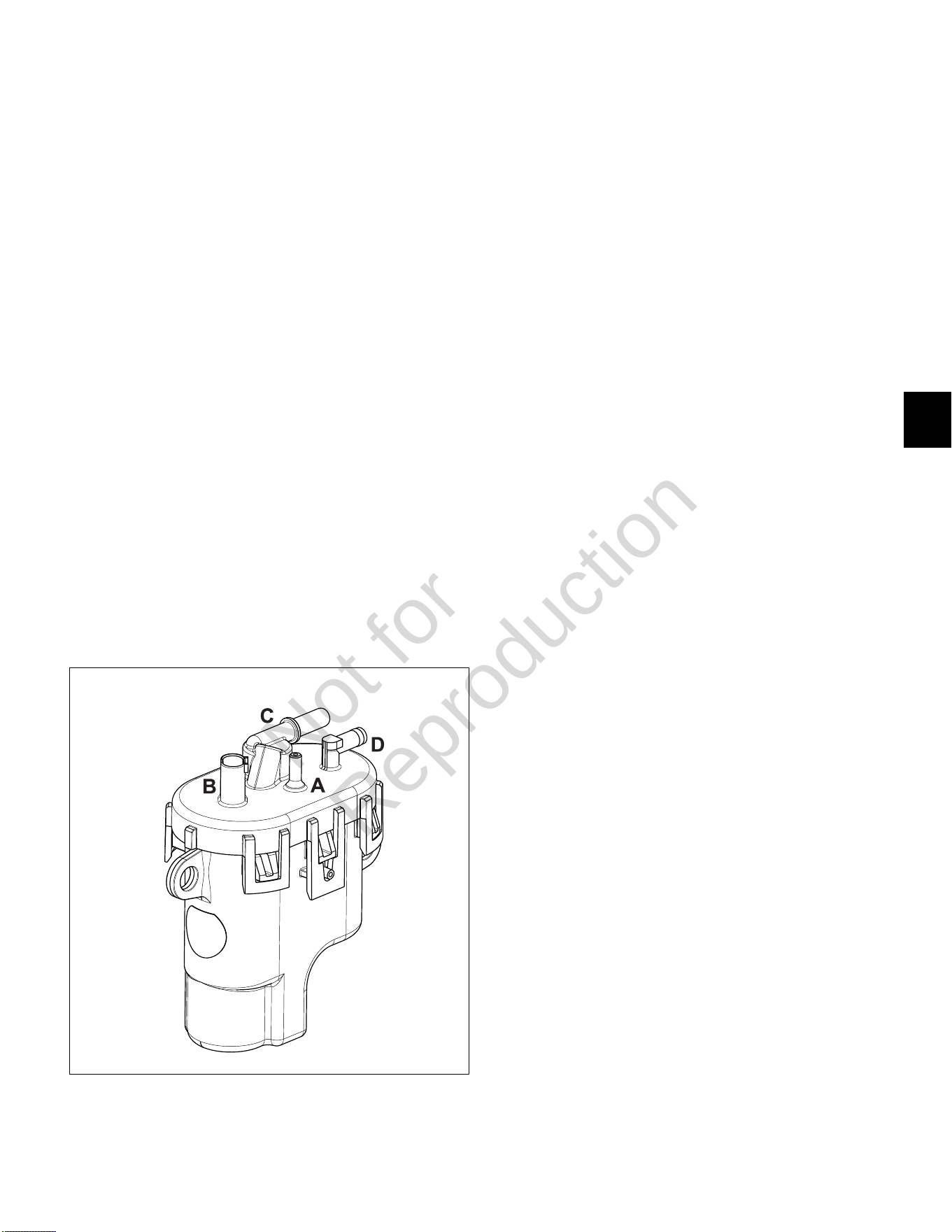
5
125
Fuel Pump Module
Removal
1. Relieve fuel system pressure. SeeCHECK/RELIEVE
FUEL SYSTEM PRESSUREin this section.
2. Remove access cover.See Access Cover/Blower
Housing, Removal, steps 1-3.
3. SeeAir Cleaner Assembly, Removal.
4. See Figure24. Squeeze clip and remove EVAP tube
(A) to throttle body adapter.
5. Remove three hex screws to release fuel pump
module from bracket.
6. Pull out grey secondary lock and press latch to
disconnect fuel pump module connector (B).
7. Squeeze two tabs on quick disconnect fitting to
release fuel rail from fuel outlet port (C).
NOTE:Wrap shop towel around fitting to catch any
fuel leakage.
8. Squeeze hose clip at fuel inlet port (D) and remove
hose from fuel filter.
9. Remove fuel pump module.
NOTE:Fuel pump module may contain a small
quantity of fuel. Hold fuel pump module with inlet and
outlet fittings pointing upward until fuel can be drained
into suitable container.
24
Installation
1. Install new fuel pump module into bracket.
2. Squeeze hose clip and install hose from fuel filter
onto fuel inlet port (D).
3. Firmly push quick disconnect fitting on fuel rail onto
fuel outlet port (C). Gently tug fitting to verify that it is
properly seated and secure.
4. Connect fuel pump module connector (B). Push in
grey secondary lock to secure.
5. Squeeze clip and install EVAP tube (to throttle body
adapter) at top of fuel pump module (A).
6. Install three hex screws to fasten fuel pump module
to bracket. Alternately tighten screws to 78-96lb-in
(9-11 Nm).
7. Turn ignition switch ON for two seconds, and then
OFF for 10 seconds. Turn the ignition switch back to
ON and check for fuel leaks.
8. See Air Cleaner Assembly, Installation.
9. Install access cover. See Access Cover/Blower
Housing, Installation, steps 7-10.
Fuel Rail/Fuel Injectors
Removal
1. Relieve fuel system pressure. SeeCHECK/RELIEVE
FUEL SYSTEM PRESSUREin this section.
2. SeeAccess Cover/Blower Housing, Removal.
3. SeeAir Cleaner Assembly, Removal.
4. Pull out green secondary lock and press tab to
disconnect fuel injector connectors.
5. See Figure25. Remove two hex flange screws to
release fuel injector cap flanges from intake manifold.
6. Remove two hex flange screws to release fuel rail
clamps from intake manifold.
7. Remove retaining clips to release fuel injector caps
from fuel injectors. Note orientation of the retaining
clips prior to removal.
8. Remove fuel injectors from intake manifold.
9. Squeeze two tabs on quick disconnect fitting to
release fuel rail from fuel pump module.
NOTE:Wrap shop towel around fitting to catch any
fuel leakage.
Not for
Reproduction
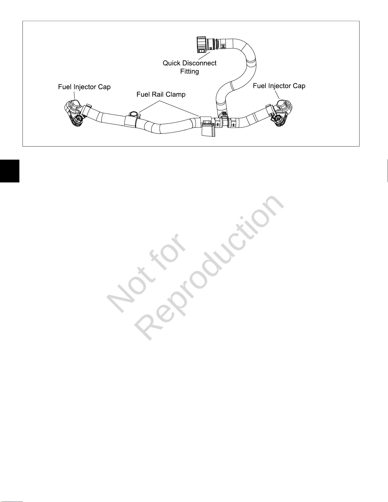
5
126
25
Installation
1. Lightly lubricate fuel injector O-rings with clean
engine oil.
2. Install fuel injectors into intake manifold.
3. Install retaining clips to secure fuel injector caps to
fuel injectors. Orient retaining clips as noted during
removal. Be sure retaining clips are fully engaged.
4. Install two hex flange screws to fasten fuel injector
cap flanges to intake manifold. Tighten screws to
104-122lb-in (12-14 Nm).
5. Install two hex flange screws to fasten fuel rail clamps
to intake manifold. Tighten screws to 78-96lb-in
(9-11 Nm).
6. Connect fuel injector connectors. Push in green
secondary locks to secure.
7. Firmly push quick disconnect fitting onto fuel pump
module. Gently tug on fitting to verify that it is properly
seated and secure.
8. Turn ignition switch ON for two seconds, and then
OFF for 10 seconds. Turn the ignition switch back to
ON and check for fuel leaks.
9. See Air Cleaner Assembly, Installation.
10. See Access Cover/Blower Housing, Installation.
CKP Sensor
Removal
1. SeeAccess Cover/Blower Housing, Removal.
2. Remove two Phillips screws to release CKP sensor
bracket from cylinder mounting bosses.
3. Disconnect CKP sensor connector.
Installation
1. Start two Phillips screws to fasten CKP sensor
bracket to cylinder mounting bosses. Alternately
tighten screws until snug.
2. On side opposite electrical connector, install
mounting plate in groove of CKP sensor housing.
3. Insert CKP sensor into bracket. Align hole in
mounting plate with hole stamped “61” on bracket.
Install TORX screw and tighten to 25-35lb-in (3-4
Nm).
4. Loosen two bracket screws and adjust as necessary
until gap between CKP sensor and flywheel tooth is
0.010 inches (0.254 mm).
5. Alternately tighten CKP sensor bracket screws to
22-35lb-in (3-4 Nm).
6. Connect CKP sensor connector.
7. See Access Cover/Blower Housing, Installation.
Air Cleaner Assembly
Removal
1. Remove plastic knob to release air filter cover.
2. Remove thumb nut from threaded stud.
3. Remove metal retainer plate.
4. Remove air filter element.
5. See A of Figure26. Remove upper hex flange screws
(1-2) to release air cleaner backplate from ECM/fuse
block bracket.
6. Remove lower hex flange screws (3-4) to release air
cleaner backplate from fuel pump module bracket.
7. Remove four hex screws (5-8) to release carburetor
shield and throttle body adapter from throttle body.
8. See B of Figure26. Squeeze clip and remove EVAP
tube (to throttle body adapter) from top of fuel pump
module.
Not for
Reproduction
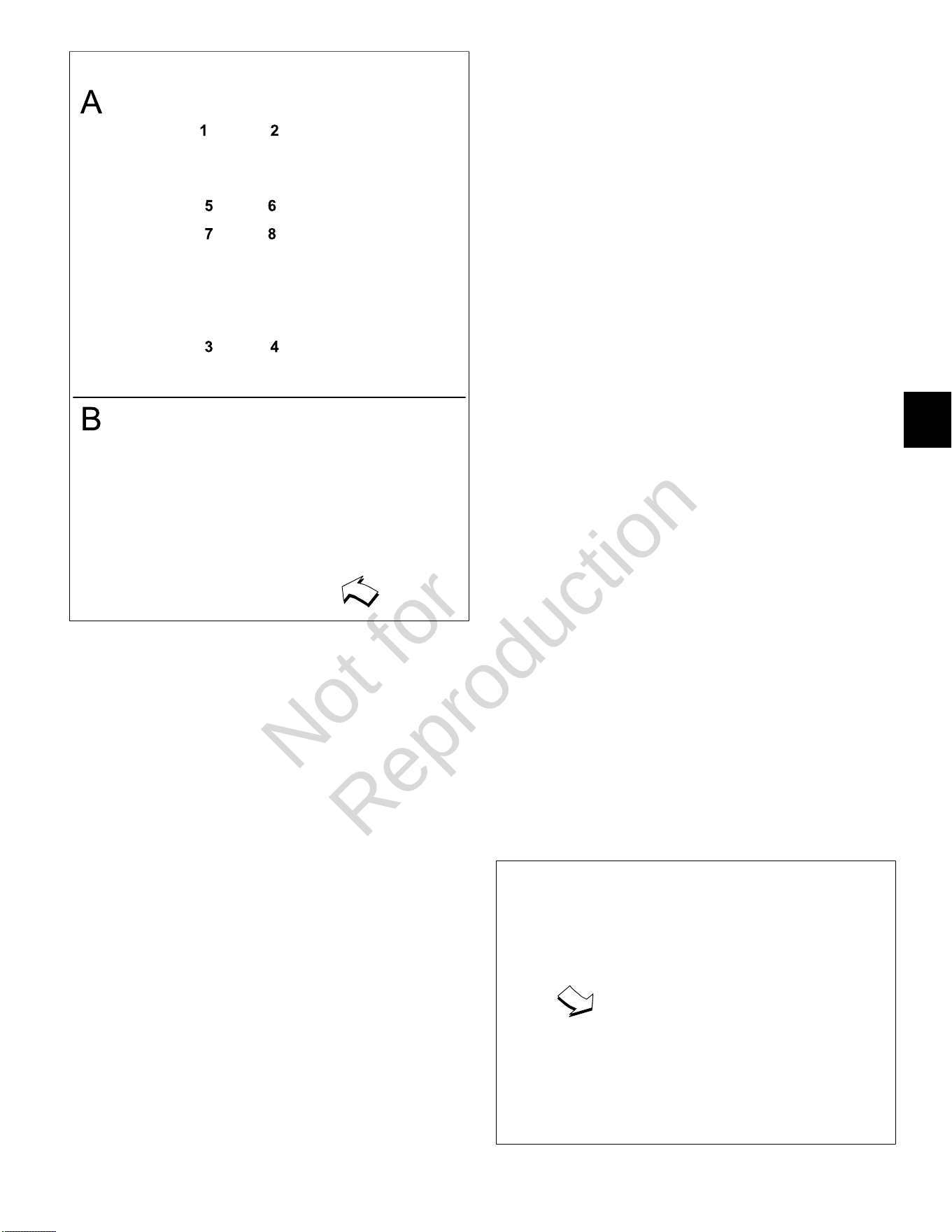
5
127
26
Installation
1. Insert four hex screws (5-8) through carburetor shield
and air cleaner backplate.
NOTE: Air cleaner backplate is stamped “Air Filter
Side” to ensure proper installation. Also, be sure
carburetor shield is oriented so that the threaded stud
is at the bottom.
2. At back of air cleaner backplate, hang gasket on four
hex screws.
3. Insert four hex screws (5-8) through throttle body
adapter and start into throttle body.
4. Start lower hex flange screws (3-4) to fasten air
cleaner backplate to fuel pump module bracket.
5. Start upper hex flange screws (1-2) to fasten air
cleaner backplate to ECM/fuse block bracket.
6. Alternately tighten four carburetor shield hex screws
(5-8) to 78-96lb-in (9-11 Nm) using a crosswise
pattern.
7. Alternately tighten four backplate hex flange screws
(1-4) to 174-217lb-in (20-25 Nm) using a crosswise
pattern.
8. Place air filter element onto air filter mount.
9. Fit metal retainer plate evenly and snugly into air filter
element.
10. Install thumb nut onto threaded stud and tighten until
snug.
11. Install air filter cover.
12. Install plastic knob onto threaded rod to secure air
filter cover.
Throttle Body
Removal
1. Remove access cover. SeeAccess Cover/ Blower
Housing, Removal, steps 1-3.
2. SeeAir Cleaner Assembly, Removal.
3. Remove two Phillips screws to release ECM and
ECM ground wire ring terminal from ECM/fuse block
bracket.
4. Remove hex flange screw to release ECM/fuse block
bracket from throttle body.
5. Remove two hex flange screws to release throttle
body from intake manifold.
6. Disconnect IAC connector.
7. Disconnect TPS connector.
Installation
1. Connect TPS connector.
2. Connect IAC connector.
3. Install two hex flange screws in throttle body flanges.
Hang new gasket on screws, so that tab points
toward idle screw with spring. See Figure 27.
4. Start hex flange screws into intake manifold.
Alternately tighten screws to 78-96lb-in (9-11 Nm).
5. Install hex flange screw to fasten ECM/fuse block
bracket to throttle body. Tighten screw until snug.
6. See Air Cleaner Assembly, Installation.
27
Not for
Reproduction

5
128
7. Tighten ECM/fuse block bracket to throttle body
screw to 78-96lb-in (9-11 Nm).
8. Slide Phillips screw through ECM flange (Grey ECM
J1 connector side) and ground wire ring terminal.
Start screw into ECM/fuse block bracket.
9. Install second Phillips screw on opposite side, and
alternately tighten screws to 35-52lb-in (4-6 Nm).
10. Install access cover. See Access Cover/Blower
Housing, Installation, steps 7-10.
EHT Sensor
NOTE:The EHT sensor is an integral part of the EFI wire
harness and is not sold separately. Replace EFI wire
harness if EHT sensor is bad.
28
EFI Wire Harness
Removal
1. SeeAccess Cover/Blower Housing, Removal.
2. SeeAir Cleaner Assembly, Removal.
3. See A of Figure29. On cylinder 2 side of engine,
proceed as follows:
• Remove screw to release fuse block cover from
ECM/fuse block bracket.
• Disconnect MAP/MAT sensor connector.
• Disconnect fuel injector connector.
• Disconnect ignition coil connector.
• Remove Phillips screw to release ground wire
ring terminal from cylinder boss.
• Disconnect ECM J2 connector.
4. See B of Figure29. On cylinder 1 side of engine,
proceed as follows:
• Disconnect ECM J1 connector.
• Remove Phillips screw to release ECM ground
wire ring terminal from ECM/fuse block bracket.
• Disconnect fuel injector connector.
• Disconnect ignition coil connector.
• Disconnect CKP sensor connector.
• Disconnect IAC connector.
5. See C of Figure29. Proceed as follows:
• Disconnect TPS connector.
• Disconnect fuel pump module connector.
• Remove TORX screw to release EHT sensor
bracket from cylinder 1.
• Disconnect 2- and 6-place (or single 8-place)
engine to chassis connectors.
• Disconnect starter solenoid ring and spade
terminals.
6. Remove two Phillips screws to remove air block
mounting plate.
7. See C of Figure29. Feed wire harness conduit and
connectors up through air block mounting plate
opening.
8. Cut two cable straps around intake manifold between
air block mounting plate and inside ignition coil
mounting bosses. Remove EFI wire harness from
engine.
Installation
1. Position new EFI wire harness at top of intake
manifold separating conduit and connectors into three
groups as shown in Figure 29.
2. See C of Figure 29. Feed wire harness connectors
and conduit down through air block mounting plate
opening to area below intake manifold.
3. See B of Figure 29. On cylinder 1 side of engine,
proceed as follows:
• Connect ECM J1 connector.
• Slide Phillips screw through ECM flange (Grey
ECM J1 connector side) and ground wire ring
terminal. Start screw into ECM/fuse block bracket
and tighten to 35-52lb-in (4-6 Nm).
• Connect fuel injector connector. Push in green
secondary lock to secure.
• Install new cable strap through ignition coil
wire harness socket connector, install over
inside ignition coil mounting boss, and connect
connector.
• Connect CKP sensor connector.
• Connect IAC connector.
4. See A of Figure 29. On cylinder 2 side of engine,
proceed as follows:
• Install screw to fasten fuse block cover to ECM/
fuse block bracket. Tighten screw to 78-96lb-in
(9-11 Nm).
Not for
Reproduction
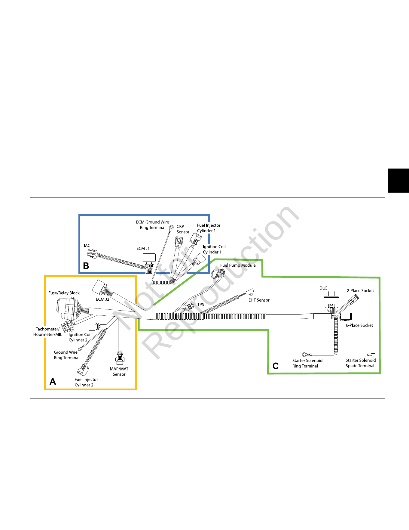
5
129
• Connect MAP/MAT sensor connector. Push in
red secondary lock to secure.
• Connect fuel injector connector. Push in green
secondary lock to secure.
• Install new cable strap through ignition coil
wire harness socket connector, install over
inside ignition coil mounting boss, and connect
connector.
• Install Phillips screw to fasten ground wire ring
terminal to cylinder boss. Tighten screw to
22-35lb-in (3-4 Nm).
• Connect ECM J2 connector.
5. See C of Figure 29. Proceed as follows:
• Connect TPS connector.
• Connect fuel pump module connector. Push in
grey secondary lock to secure.
• Orient EHT sensor with end rotated against tab
on cylinder 1. Install TORX screw and tighten to
35-52lb-in (4-6 Nm). See Figure 28.
• Connect starter solenoid ring and spade
terminals.
• Connect 2- and 6-place (or single 8-place) engine
to chassis connectors.
6. Install two Phillips screws (with captive washers) to
fasten air block mounting plate to cylinder. Alternately
tighten screws to 22-35lb-in (3-4 Nm).
7. Install new cable strap around intake manifold
between air block mounting plate and inside cylinder
2 ignition coil mounting boss capturing convoluted
tubing of ignition coil and fuel injector.
8. Install new cable strap around intake manifold
between air block mounting plate and inside cylinder
1 ignition coil mounting boss capturing fuel injector,
ignition coil and CKP sensor conduit.
9. See Air Cleaner Assembly, Installation.
10. See Access Cover/Blower Housing, Installation.
29
IAC
Removal
1. Remove access cover. See Access Cover/Blower
Housing, Removal, steps 1-3.
2. See Air Cleaner Assembly, Removal.
3. Disconnect IAC connector.
4. Remove two Phillips screws to release IAC from
throttle body.
Installation
1. Install two Phillips screws to fasten IAC to throttle
body. Alternately tighten screws to 22-35lb-in (2-4
Nm).
2. Connect IAC connector.
3. See Air Cleaner Assembly, Installation.
4. Install access cover. See Access Cover/Blower
Housing, Installation, steps 7-10.
Not for
Reproduction
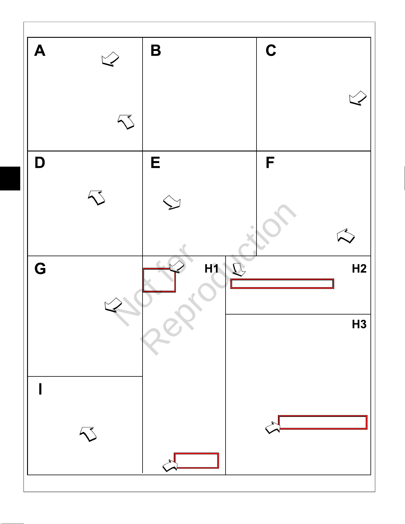
5
130
30
Not for
Reproduction
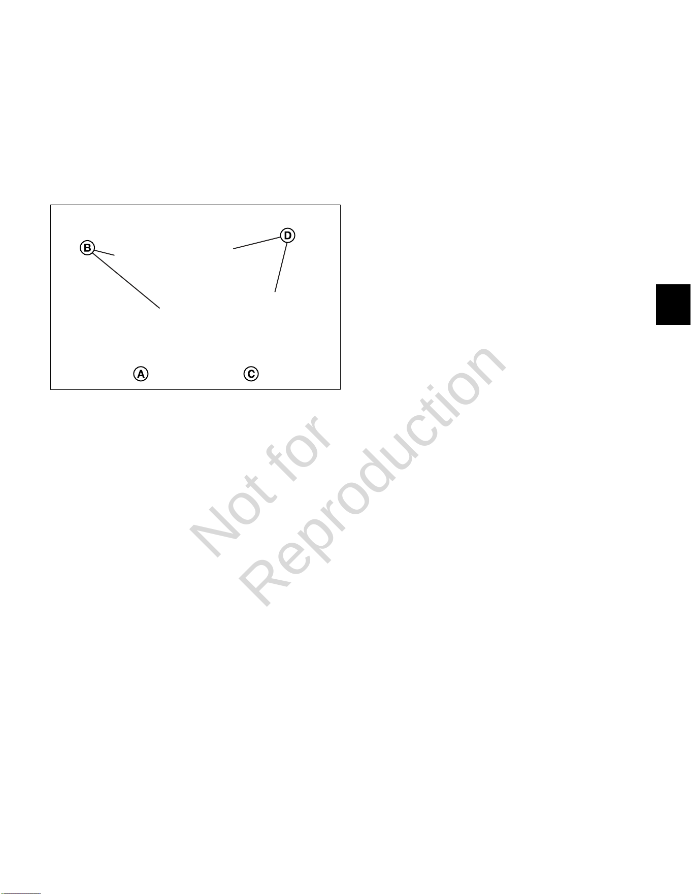
5
131
TPS
NOTE: See Figure 31. The late style non adjustable
TPS (A) can be identified by the round screw holes (B)
in the mounting flange, whereas the early style TPS (C)
is slotted (D), so that the unit can be rotated if using a
DVOMfor adjustment. Engines with the late style TPS
may also come equipped with a tamper proofTORXidle
set screw.
31
Non Adjustable TPS (Late Style)
Removal
1. See Throttle Body, Removal.
2. Remove two Phillips screws to release TPS from
throttle body.
Installation
1. Install two Phillips screws to fasten TPS to throttle
body. Alternately tighten screws to 10-16lb-in (1-2
Nm).
2. See Throttle Body, Installation.
Adjustable TPS (Early Style)
Removal/Installation/Adjustment
1. See Throttle Body, Removal.
2. Remove two Phillips screws to release TPS from
throttle body. See A and B of Figure 30.
3. Remove dead idle screw with spring from throttle
body. See C of Figure 30.
4. Mark throttle plate position for ease of installation.
See D of Figure 30.
5. Remove two screws to release throttle plate. See E of
Figure 30.
6. Rotate throttle, so that lever contacts the dead idle
screw boss. See F of Figure 30.
7. Install two Phillips screws to fasten new TPS to
throttle body, but leave loose for later adjustment.
See G of Figure 30.
8. Apply Loctite 271 or equivalent to two throttle plate
screws. Install screws to fasten throttle plate to
throttle body. Alternately tighten screws to 8lb-in (1.0
Nm).
9. Install dead idle screw with spring, but leave loose for
later adjustment.
NOTE: If Diagnostic Tool is not available, use DVOM
and follow instructions beginning at step 20.
Using Diagnostic Tool (Part No. 19636)
10. See Throttle Body, Installation, steps 1-9.
11. Run the engine at no load idle, throttle in the idle
position.
12. See H1 of Figure 30. Using the Diagnostic Tool,
select the Dashboard icon in the left sidebar to view
the Dealer tab. Select the Test Procedures tab in
the lower left corner.
13. See H2 of Figure 30. Slew the Idle Air Control
Position (Steps) to 0 steps.
14. Adjust the dead idle screw until the engine runs at
600 +/- 50 RPM.
15. Turn the engine off.
16. See H3 of Figure 30. Close the Test Procedures
tab, and with the throttle resting against the dead idle
screw, use the software to adjust the TPS Voltage to
0.73 +/- .02 volts.
17. Alternately tighten two TPS screws to 10-16lb-in (1-2
Nm).
18. Install access cover. See Access Cover/Blower
Housing, Installation, steps 7-10.
19. Proceed to step 25 to reset ECM memory.
Using DVOM
20. See Throttle Body, Installation, steps 1-4.
21. Run engine at no load idle, throttle in the idle position.
22. Use index finger or plug to block IAC air passage.
See I of Figure 30.
23. While IAC air passage is blocked, adjust dead idle
screw until engine runs at 600 +/-50 RPM.
24. Turn engine OFF and proceed as follows:
A. Back probe terminal 3 (Pink/Black wire) of TPS
connector.
B. Connect terminal 3 back probe to red meter test
lead on DVOM.
C. Back probe terminal 2 (Brown wire) of TPS
connector.
D. Connect terminal 2 back probe to black meter
test lead on DVOM.
Not for
Reproduction

5
132
E. Set DVOM to read volts DC.
F. Turn Ignition ON, Engine OFF.
G. Observe voltage on DVOM.
H. With throttle resting against the dead idle screw,
rotate the TPS until the output voltage is 0.73 +/-
0.02 volts.
I. Alternately tighten two TPS screws to 10-16lb-in
(1-2 Nm).
J. See Throttle Body, Installation, steps 5-9.
25. Reset ECM memory as follows:
A. Turn Ignition OFF for at least 10 seconds.
B. Cycle Ignition ON and OFF five times in five
seconds.
C. End cycle in the OFF position and wait at least 10
seconds.
D. Turn Ignition ON to reset ECM memory to the
default values.
HO
2
Sensor
Removal
1. Remove access cover. SeeAccess Cover/Blower
Housing, Removal, steps 1-3.
2. SeeAir Cleaner Assembly, Removal.
3. Disconnect HO
2
sensor connector.
4. Rotate sensor body hex counter-clockwise to release
sensor from muffler.
Installation
1. Rotate sensor body hex clockwise to secure sensor
to muffler. Tighten to 146-173lb-in (16-19 Nm).
2. Connect HO
2
sensor connector.
3. See Air Cleaner Assembly, Installation.
4. Install access cover. See Access Cover/Blower
Housing, Installation, steps 7-10.
Not for
Reproduction

5
133
This page is intentionally left blank.
Not for
Reproduction
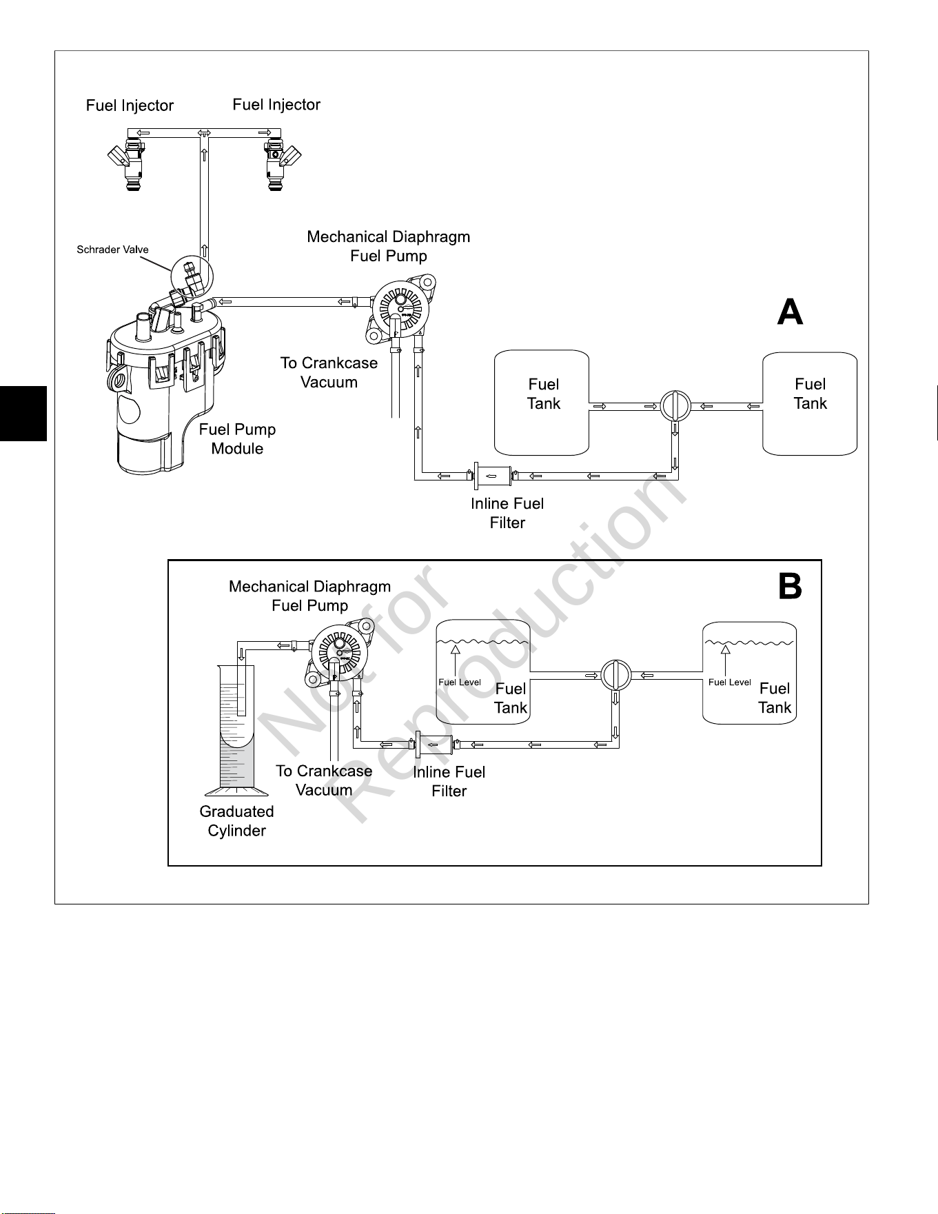
5
134
32
Not for
Reproduction

5
135
MECHANICAL DIAPHRAGM FUEL PUMP FOR MODEL 490000
Volumetric Test
Perform a volumetric test to verify that the proper
amount of fuel is being delivered to the engine. See A
of Figure32for a typical fuel flow diagram for Model
490000. Proceed as follows:
1. Relieve fuel system pressure. SeeCHECK/RELIEVE
FUEL SYSTEM PRESSUREin this section.
2. Remove battery negative cable (black) from battery
negative (-) terminal.
3. Squeeze clip at fuel outlet port and remove hose to
fuel pump module.
NOTE:Wrap shop towel around fitting to catch any
fuel leakage.
4. Obtain a stop watch and a graduated cylinder.
5. Attach suitable hose to fuel outlet port and direct free
end into graduated cylinder. See B of Figure32.
6. Install battery negative cable (black) to battery
negative (-) terminal.
7. Start engine and watch for fuel discharge from outlet
port hose. Start the stopwatch as soon as fuel flow is
observed.
8. Run engine for 30 seconds at 2200 RPM.
9. After the time has elapsed, turn off the engine and
stop the watch.
10. Measure the volume of fuel discharged into
the graduated cylinder. See the table below for
the approximate amount of fuel that should be
discharged.
Pump Fuel for 30 Seconds
237 m
0.5 pint
0.25 quart
Approximate Fuel Amount
1.0 cup
NOTES:
• Position the fuel tank so that it is near level
with the fuel pump. Do not place the graduated
cylinderBELOWthe fuel pump or gravity feed will
produce false results.
• The engine will run longer than the 30 second
test interval using fuel trapped in the fuel pump
module.
• View the graduated cylinder with your eyes
directly level with the fuel. Note that the fuel
curves up the sides of the graduated cylinder.
This curve is called a meniscus. For the most
accurate reading, read the measurement from the
bottom of the meniscus.
• The volumetric measurement is only
approximate. The fuel pump is likely functioning
properly if the test results are within 10% of the
approximate fuel amount.
Engine Cranks But Will Not Start
Use the starter to turn the engine over for 10
seconds. See the table below for the approximate
amount of fuel that should be discharged.
Crank Engine for 10 Seconds
65 ml
0.13 pint
0.06 quart
Approximate Fuel Amount
0.27 cup
Not for
Reproduction
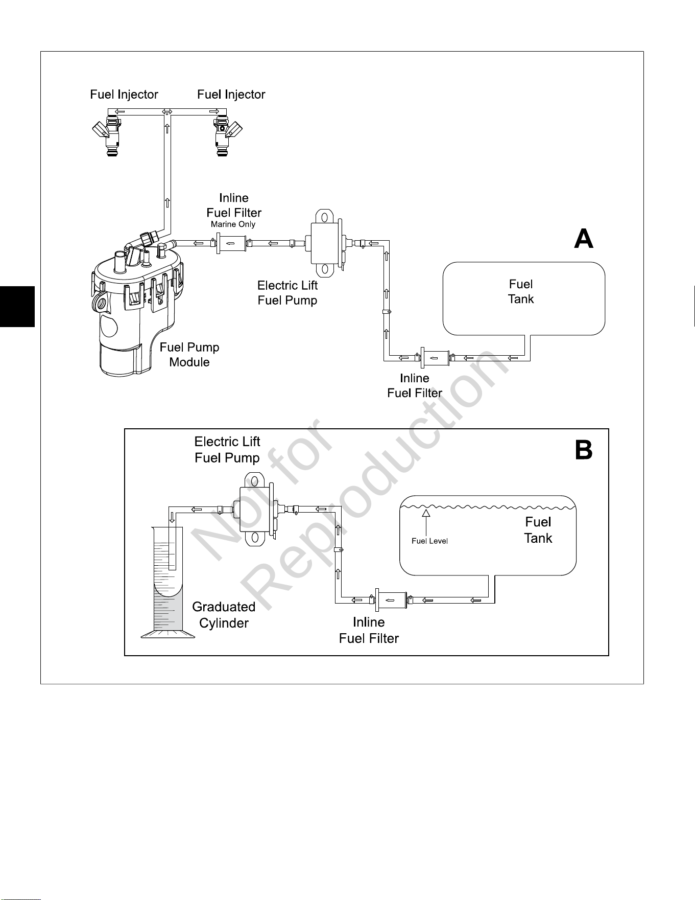
5
136
33
Not for
Reproduction

5
137
ELECTRIC LIFT FUEL PUMP FOR MODELS 540000/610000
Volumetric Test
Perform a volumetric test to verify that the proper
amount of fuel is being delivered to the engine. See A
of Figure33for a typical fuel flow diagram for Models
540000/610000. Proceed as follows:
1. Relieve fuel system pressure. SeeCHECK/RELIEVE
FUEL SYSTEM PRESSUREin this section.
2. Remove battery negative cable (black) from battery
negative (-) terminal.
3. Squeeze clip at fuel outlet port and remove hose to
fuel pump module.
NOTE:Wrap shop towel around fitting to catch any
fuel leakage.
4. Obtain a stop watch and a graduated cylinder.
5. Attach suitable hose to fuel outlet port and direct free
end into graduated cylinder. See B of Figure33.
6. Install battery negative cable (black) to battery
negative (-) terminal.
7. Start engine and watch for fuel discharge from outlet
port hose. Start the stopwatch as soon as fuel flow is
observed.
NOTE:The fuel pump primes for 2 seconds when
the ignition is turned ON. Do not count this fuel in the
volumetric measurement.
• If the engine will not run, connect a fused jumper
wire from the fuel pump electrical connector to
12v B+. SeeSECTION 3 - WIRE SCHEMATICS
AND PIN-OUTSfor reference.
8. After 30 seconds has elapsed, turn off the engine and
stop the watch.
9. Measure the volume of fuel discharged into
the graduated cylinder. See the table below for
the approximate amount of fuel that should be
discharged.
Pump Fuel for 30 Seconds
478 ml
1.0 pint
0.5 quart
Approximate Fuel Amount
2.0 cup
NOTES:
• Position the fuel tank, so that it is near level
with the fuel pump. Do not place the graduated
cylinderBELOWthe fuel pump or gravity feed will
produce false results.
• The engine will run longer than the 30 second
test interval using fuel trapped in the fuel pump
module.
• View the graduated cylinder with your eyes
directly level with the fuel. Note that the fuel
curves up the sides of the graduated cylinder.
This curve is called a meniscus. For the most
accurate reading, read the measurement from the
bottom of the meniscus.
• The volumetric measurement is only
approximate. The fuel pump is likely functioning
properly if the test results are within 10% of the
approximate fuel amount.
Not for
Reproduction

5
138
This page is intentionally left blank.
Not for
Reproduction

Not for
Reproduction
M490000/M540000/M610000 Repair Manual
80021828 (Revision A)
BRIGGS&STRAT TON, LLC
CUSTOMER EDUCATION
Milwaukee, WI 53201 USA
Copyright ©2020. All rights reserved.
VANGUARDPOWER.COM
Vanguard
®
BIG BLOCK
™
and 810
EFI Diagnostic and Repair
M490000/M540000/M610000
REPAIR MANUAL
Not for
Reproduction