
MILWAUKEE ELECTRIC TOOL CORPORATION
13135 W. Lisbon Road, Brookfi eld, WI 53005
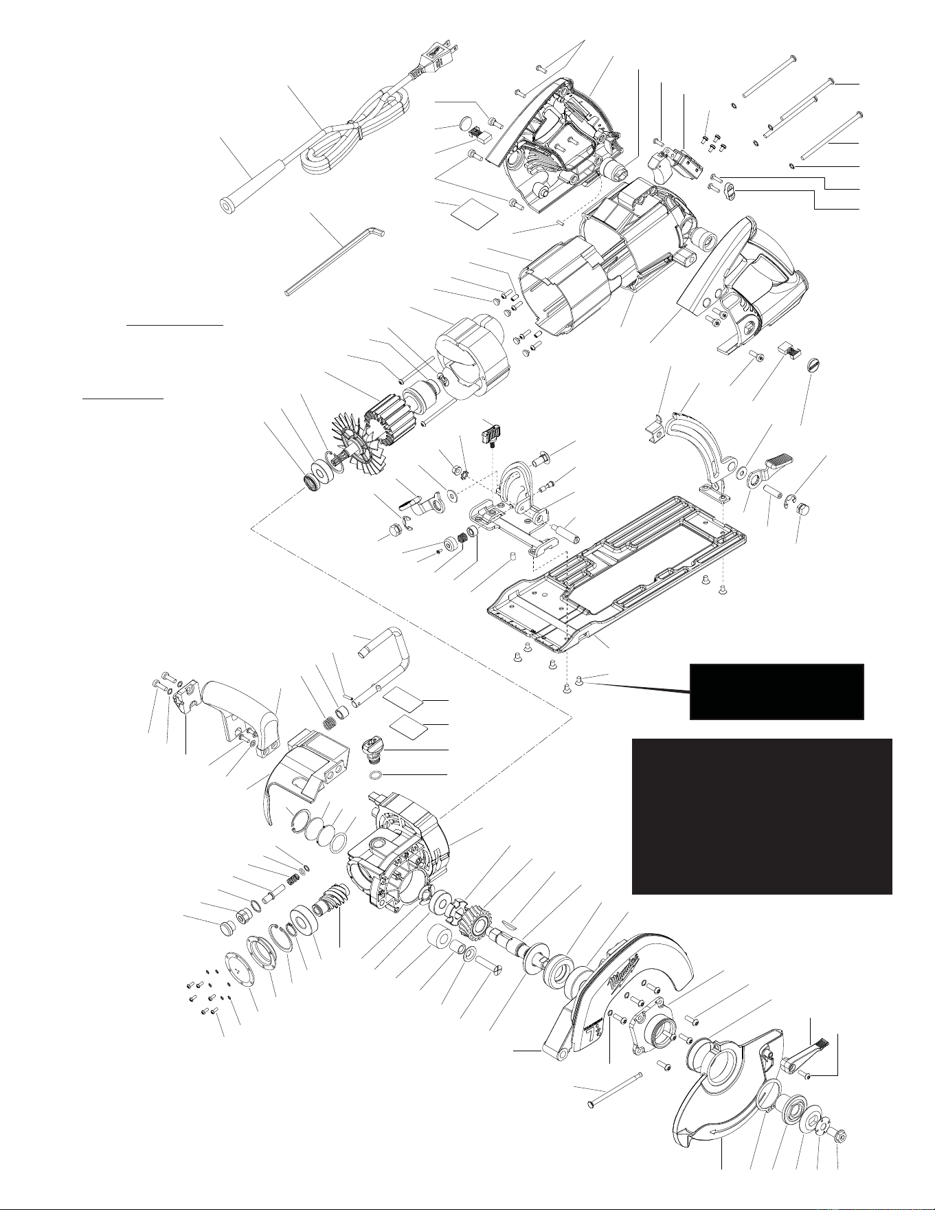
Drwg. 1
54-40-1922
SERVICE PARTS LIST
BULLETIN NO.
B20C
REVISED BULLETIN
54-40-1921
DATE
Aug. 2013
WIRING INSTRUCTION
58-01-0355
STARTING
SERIAL NUMBER
FIG. PART NO. DESCRIPTION OF PART NO. REQ.
1 02-04-2805 Bearing 1
2 02-04-2810 Bearing 1
3 02-04-2815 Bearing 1
4 02-04-2820 Bearing 1
5 02-04-2825 Bearing 1
6 05-59-0130 Domed Nut, 5/16-18 UNC 1
7 05-59-0135 Domed Nut, 5/16-18 UNC 1
8 05-70-0335 Screw, Torx, T30, M8 x 40 mm 1
9 05-74-0010 Screw, Torx, T20, M4 x 16 4
10 05-74-0900 Screw, Torx, T10, M3 x 10 mm 6
11 05-74-0905 Screw, Torx, T20, M5 x 20 mm 7
12 05-74-0910 Screw, Torx, T25, M5 x 108 mm 1
13 05-74-0915 Screw, Torx, T25, M5 x 95 mm 3
14 06-81-0150 Screw, Torx, T20, 6-19 x 5/8 2
15 05-74-0930 Screw, Cross Drive, M3.5 x 12 mm 4
16 05-74-0935 Screw, Torx, T25, M5 x 15 mm 2
17 05-74-0940 Set Screw, Torx, T20, M6 x 8 mm 2
18 05-74-0950 Screw, Torx, T20, M3 x 5 mm 1
19 05-74-0955 Screw, Torx, T25, M5 x 6 mm x 9.5 mm 6
20 05-74-0960 Field Screw, Torx, T25, M5 x 50 mm 2
22 05-74-1005 Screw, Torx, T25, M6 x 10 mm 7
23 06-82-5314 Screw, Torx, T20, 10-24 x 1/2" Pan Hd. 1
24 05-78-0305 Screw, Slotted Torx, Metric 4
25 05-84-0980 Set Screw, M6 x 8 mm 1
26 05-86-0200 Screw, Torx, T20, M5 x 11 mm 2
27 05-90-0003 Spring Lock Washer 6
28 05-90-0160 Lock Washer 1
29 05-90-0195 Lock Washer 9
30 06-10-3195 Carriage Bolt, 5/16-18 x 3/4 1
31 06-57-0050 Hex Nut, M6 1
32 06-65-0100 Lock Pin 1
33 06-75-0175 Blade Screw, 3/8-16 x 19 mm, LH Thread 1
34 06-83-0900 Screw, 5/16-18 x 1-1/8 1
35 10-15-0312 Spanish Warning Label 1
36 10-15-0313 French Warning Label 1
38 12-20-0631 Nameplate 1
39 14-74-0100 Bevel Lever Assembly 1
40 14-74-0245 Shoe 1
41 16-70-0173 Armature 1
42 18-70-0143 Field 1
43 22-18-0134 Brush Tube Assembly 2
44 22-18-0148 Brush Assembly 2
45 22-32-0320 Brush Cap 2
47 22-64-1104 Cord (Double Insulated) 1
48 23-39-0205 External Retaining Ring 1
49 23-66-1812 Switch 1
50 25-16-0105 Bevel Bracket 1
51 25-16-0125 Elevation Bracket 1
52 28-41-0725 Upper Guard 1
53 28-41-0730 Lower Guard 1
54 28-14-6477 Machined Gear Case 1
55 28-50-0575 Motor Housing 1
56 31-44-0670 Heat Shield 1
57 31-44-0675 Bale Handle 1
58 31-44-1107 LH Handle 1
59 31-44-1108 RH Handle 1
60 31-50-0190 Motor Sleeve 1
61 32-90-0114 Worm Gear 1
62 32-91-0121 Worm Gear Pinion 1
63 34-40-1555 O-Ring 1
64 34-40-1560 O-Ring 1
65 34-80-5380 Retaining Ring, 32 mm 2
66 34-80-2965 Retaining Ring, 17 mm 1
67 34-80-2975 Retaining Ring, 40 mm 1
FIG. PART NO. DESCRIPTION OF PART NO. REQ.
68 36-18-0595 Spindle 1
69 40-50-0045 Guard Spring 1
70 40-50-8305 Wave Spring 1
71 40-50-8315 Wave Spring 1
72 40-50-8345 Compression Spring 1
73 40-50-8365 Compression Spring 1
74 40-50-8370 Compression Spring 1
75 42-14-0465 Rubber Bladder 1
76 42-36-2170 C-Channel Depth Bracket 1
77 42-36-2175 Depth Lever Bracket 1
78 42-38-0225 Rubber Bumper 1
79 42-40-0090 Bushing 1
80 42-40-1005 Lockout Bushing 1
81 42-52-1020 Spindle Lock Cap 1
82 42-52-1050 Oil Fill Cap 1
84 42-68-0605 Cord Clamp 1
85 42-70-0140 E-Clip 2
86 42-92-1535 Cover Bladder 1
87 43-34-0275 Inner Blade Flange 1
88 43-34-0285 Outer Blade Flange 1
89 43-50-0120 Inner Oil Glass 1
90 43-50-0110 Outer Oil Glass 1
91 43-50-0115 Blade Spring Washer 1
92 43-70-0025 Hinge Pin 1
93 43-74-0055 Rafter Hook 1
94 43-74-0095 Mount Hook 1
95 43-78-0580 Lower Guard Hub 1
96 43-96-0240 Wooddruff Key 1
97 43-98-0550 Edge Guide Lock 1
98 44-10-0420 Guard Lever 1
99 44-20-0830 Spindle Lock Disc 1
100 44-60-1145 Spring Pin 1
101 44-60-1155 Bevel Pin 1
102 44-68-0670 Rubber Plug 4
103 44-76-0050 Strain Relief 1
104 45-06-0107 Oil Seal 1
105 45-06-0285 Oil Seal 1
106 45-06-0295 Washer 1
107 45-06-0296 O-Ring 1
108 45-12-0030 Oil Shield Washer 1
109 45-22-0605 Lower Guard Sleeve 1
110 45-22-0390 Bumper Sleeve 1
111 45-88-0010 Flat Washer 2
112 45-88-1385 Bevel Cap 1
113 45-88-1390 Washer 1
114 45-88-1395 Washer 2
115 45-88-7465 O-Ring 1
116 45-88-7480 Washer 1
117 45-96-0280 Blade Wrench 1
118 31-53-0105 Rubber Slug 1
49-32-0050 Oil, 8 Oz. (Not Shown) 1
42-41-4119 7-1/4" Circle Saw Blade (Not Shown) 1
48-55-1101 Steel Carrying Case (Not Shown) 1
00
0
EXAMPLE:
Component Parts (Small #) Are Included
When Ordering The Assembly (Large #).
SPECIFY CATALOG NO. AND SERIAL NO. WHEN ORDERING PARTS
CATALOG NO. 6477-20
7-1/4" Worm Drive Saw
= Part number change from
previous service parts list.
16
100
29
94
57
117
26
82
56
64
73
79
111
65
90
89
63
32
72
107
80
81
27
10
3
62
106
115
86
75
67
66
70
4
99
78
110
116
8
108
105
5
52
69
95
109
53 48 87 88
11
91 33
23
29
98
25
113
68
96
74
112
18
61
54
7
39
85
97
31
28
50
114
103
47
19
45
44
19
15
59
15
43
49
24
29
13
12
84
14
58
51
44
19
45
77
114
34
85
6
40
22
93
35
36
104
2
65
41
20
1
71
42
102
38
60
55
9
30
101
17
92
76
(3 X)
Loctite®
Loctite®
Loctite®
(4 X for handle)
118
Functionally check the spindle
lock mechanism. Spindle lock
must return briskly when
released from
engagement
in gear.
The Depth Adjustment
Lever [77] should be
above the plane of the
shoe and .50" minimum
from the tip of the lever to the
right handle half vent when tightened.
Functionally check
the Lower Guard [53] with
the saw set at full depth of cut.
Place the saw upside down with
the shoe horizontal. Fully retract the guard using
guard lever and than release it. The guard must
close briskly. Repeat the guard check two more times.
Install long Motor Housing Screw [12]
(108mm) through screw opening in
Motor Housing [55], located beneath
the C-Channel Depth Bracket
stud [76].
Place a drop of white glue onto each
Rubber Plug [102] prior to reinstalling
into pockets of Motor Sleeve [60].
When installing Field [42] into the
Motor Sleeve [60], make sure the
white fi eld lead is in the wire
trap before securing
Field Screws [20].
Lubricate inside lip and
outside diameter of Oil Seals
[104,105] prior to installing
into Gear Case [54].
Rubber Slug [118] is located
in the bottom area of the
handle halves. Place a
drop of glue or RTV to
secure in place.
Shoulder side of
Locking Cog [99] to
face Worm Gear [61].
Recessed (cut groove) on Worm Gear [61]
to face threaded end of Spindle [68].
Concave side of Blade Spring Washer [91]
to face Outer Flange [88].
Blade Screw [33] has a left hand thread.
MAINTAINING OIL LEVEL
Check oil level before use. To check level, set
saw for maximum depth, rest it fl at on its shoe
and check oil level window. Oil level should be
below max oil level line on tool (about 1/2 oz.).
If oil level is low:
1. Add oil by setting the saw on its shoe and
remove the oil plug.
2. Pour oil into chamber. DO NOT OVER FILL.
3. When the proper oil level is reached,
replace the oil plug.
NOTE: For item #22, some earlier
tools may have used 05-74-0970
(M5 x 10 Flat Hd. T-20 screw). A
drop of "Blue" Loctite, Type 242 is
needed on the threads.