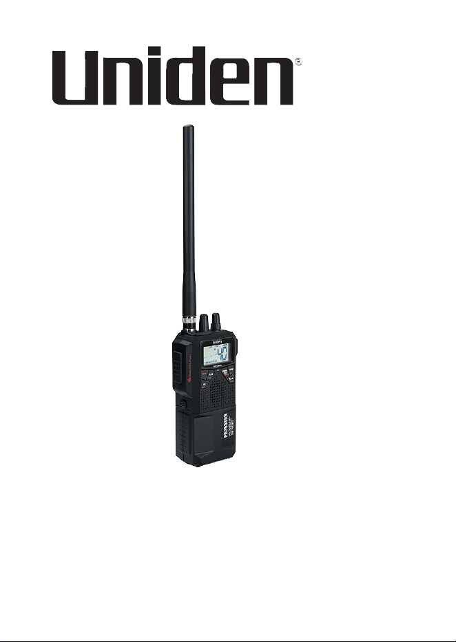
PRO538HHFM
Handheld CB Radio
Printed in Vietnam
U01UT433ZZA(0)
© 2022 Uniden America Corp.
Irving, Texas


CONTENTS
INTRODUCTION .............................................................................5
FEATURES ..................................................................................5
SAFETY NOTICE ........................................................................6
UNIDEN CONTACT INFORMATION ...........................................6
INCLUDED IN YOUR PACKAGE ...................................................6
PARTS OF THE RADIO ..................................................................7
DEFINITIONS ..............................................................................8
LCD ...............................................................................................10
SETUP ........................................................................................... 11
INSTALL ANTENNA ..................................................................11
Rubber Antenna ....................................................................12
External Antenna ..................................................................12
CONNECT TO POWER.............................................................12
Rechargeable Ni-MH Batteries ............................................. 13
Alkaline Batteries ..................................................................15
In-Vehicle Adapter ................................................................17
CONNECT EXTERNAL SPEAKER AND MICROPHONE .........18
OPERATION .................................................................................18
BASIC OPERATION ..................................................................18
EMERGENCY OPERATION ...................................................... 22
DUAL WATCH ...........................................................................22
Programming Dual Watch Channels .................................... 22
AUTOMATIC NOISE LIMITER ..................................................22
WEATHER .................................................................................23
MAINTENANCE ............................................................................23
TROUBLESHOOTING ..................................................................23
CB OPERATION ........................................................................24
CB Communication Codes ................................................... 24
SERVICE AND REPAIR INFORMATION...................................25

4
FREQUENCY LISTS .....................................................................26
CB CHANNEL FREQUENCY LIST ............................................26
WEATHER CHANNEL FREQUENCY LIST ..............................27
SPECIFICATIONS .........................................................................28
GENERAL .................................................................................. 28
TRANSMITTER .........................................................................29
RECEIVER ................................................................................29
FCC PART 15 AND ISED COMPLIANCE ...................................30
FCC AND ISED STATEMENT .......................................................32
ISED ANTENNA STATEMENT ..................................................34
ÉNONCÉ D’ANTENNE ISED ....................................................34
ONE-YEAR LIMITED WARRANTY ..............................................34

5
INTRODUCTION
The PRO538HHFM radio is a hand-held radio designed for use in the
Citizens Band (CB) Radio Service. It will operate on any of the 40 CB
frequencies authorized by the Federal Communications Commission
(FCC). Your radio features a superheterodyne circuit with Phase
Locked Loop techniques to assure precise frequency control.
NOTE: Make sure you have read and understood part 95 of the
FCC rules and regulations before using the transmitter.
FEATURES
• 40 CB channels (AM/FM modes)
• 10 Weather channels
• AGC (Automatic Gain Control) for a constant sound level.
• Automatic Noise Limiter to reduce pulse noise.
• Backlight On/O; Dual backlight colors (Amber and White)
• Battery pack for 8 AA Ni-MH or 6 AA alkaline batteries (batteries
are not included).
• Compatible with CB MIC hanger.
• Dual Channel Watch
• External speaker jack and external MIC jack. Includes In-Vehicle
adapter.
• Full Channel Scan
• High/Low power saver switch (HI = 4W; LOW = 1W)
• Instant Channel 9/19
• Key Lock
• Portable and In-Vehicle Use
• RF Gain Control
• Rotary Channel Selector
6
SAFETY NOTICE
• Do not expose the PRO538HHFM to water or extreme
temperatures.
• Do not leave batteries installed over a long period of time as
leakage may occur and cause damage to the radio.
• Never use dierent batteries from the ones suggested.
• Never use harsh chemicals to clean this radio. Use a damp soft
cloth.
UNIDEN CONTACT INFORMATION
You can get answers 24/7 at our website: www.uniden.com.
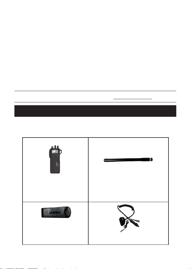
INCLUDED IN YOUR PACKAGE
If any of these items are missing or damaged, immediately contact
your place of purchase or www.uniden.com.
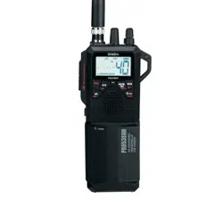
PRO538HHFM Radio
(shown with Ni-MH battery
case attached)
Rubber (Whip) Antenna
Belt Clip
In-Vehicle Adapter
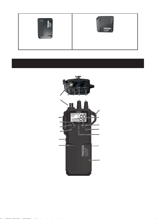
7
Ni-MH Battery Case
Alkaline Battery Case
Not shown: Hanger MIC with Screw and Wrist Strap
PARTS OF THE RADIO
3
Key 1
2
8
6
4
J1
5
1
K2K1
J2
J - Jack
K - Knob
Key - Key
None - Other
LEGEND
Key 2
Key 3
Key 4
Key 5
Key 6
7

8
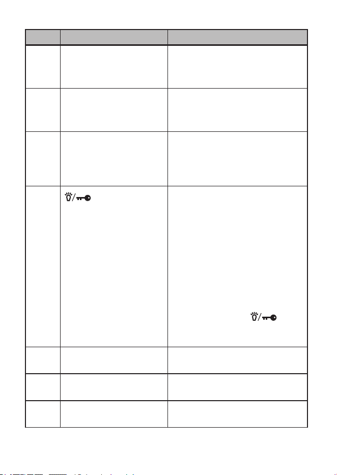
DEFINITIONS
ITEM NAME PURPOSE
J1 External Microphone
jack
Attach external microphone (not
included)
J2 External Speaker jack Attach external speaker (not
included)
K1 CH/RF GAIN knob Channel: Turn knob to select
channels.
RF Gain (AM Only): Press
FUNC + GAIN key and turn this
knob to adjust receiving gain.
Color Selection mode: Press
FUNC + COLOR key and turn
this knob to change backlight
color.
Scan mode: Resume scanning
or change scan direction.
K2 Power/VOL; SQ Turns power on and o and
adjusts volume and squelch
levels.
Key 1 9/19/DUAL Instantly recall channels 9 and
19.
Press FUNC and this key to
enter Dual Channel Watch
mode.
Press FUNC and hold this
key to program Dual Watch
Channels.
Key 2 FUNC Function key. Press this key to
unlock secondary key functions.
9
ITEM NAME PURPOSE
Key 3 ANL/GAIN Press to turn ANL on and o.
Press FUNC and this key to
access RF Gain Setting Mode.
Key 4 AM/FM (PWR H/L) Press to enter AM or FM modes.
Press FUNC and this key to set
power to high or low.
Key 5 SCAN/WX Press to start and stop
scanning.
Press FUNC. and this key to
access Weather Channels.
Key 6
/COLOR
Press to turn backlight on/o.
NOTE: Backlight does not
support the orange
letters on the keys.
Press and hold to turn keylock
on/o.
Press FUNC and this key
to enter color setting mode.
Turn the CH/RF GAIN knob to
select either an amber or white
background. Press /
COLOR to set it (see page
19).
1 Antenna Location for attaching the rubber
whip antenna.
2 Push-to-Talk button Push to transmit (talk) to other
radios.
3 Battery Case Release Slide up to release battery case
from the unit.
10
ITEM NAME PURPOSE
4 Charge LED Turns red when battery begins
charging.
NOTE: The LED does not
indicate when charging is
complete.
5 Clip Location Use a carabiner clip (not
included) to attach the radio to a
belt loop, strap, etc.
6 MIC Microphone Location
7 Charging Jack (Ni-MH
battery case only)
Connect DC charge plug from
In-Vehicle adapter.
8 Battery Case Location of Ni-MH or alkaline
battery cases or In-Vehicle
adapter when connected to the
PRO538HHFM. (Ni-MH battery
case shown.)
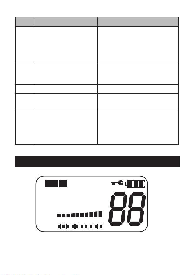
LCD
TX
F
WX DW HI
LO
SIG
PWR
1
3
5
9
+30
0.5
1 2 3 4
AM FM
ANL
SCAN
GAIN
11
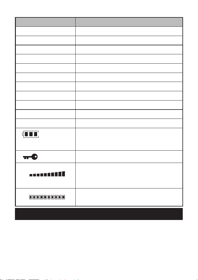
LCD ITEM MEANING
TX Transmitting indicator
F Function indicator
AM AM mode indicator
FM FM mode indicator
ANL Automatic Noise Limiter indicator
WX Weather Channel indicator
DW Dual Watch indicator
HI TX Power indicator: HI = 4W
SCAN Scan function active
LO TX Power indicator: LO = 1W
88 Channel Number/RF Gain (0 - 10)
Battery Strength (4 levels - 3, 2, 1, and
Low Battery. Battery icon blinks in Low
Battery mode.)
Key lock function active
SIGNAL
POWER
1
3
5
9
+30
0.5
1 2 3 4
S/RF meter (10 steps)
Strength of incoming signal; Strength of
transmission power.
GAIN
RF Gain Level indicator (10 steps)
SETUP
INSTALL ANTENNA
The PRO538HHFM can use either a rubber “whip” antenna or an
external antenna (not included).

12
Rubber Antenna
1 Insert the rubber antenna (included) onto the radio’s antenna jack.
2 Rotate the antenna clockwise until it clicks into place.
NOTE: If using the rubber antenna or connecting the external
antenna to the radio’s antenna terminal, the PRO538HHFM must
use either of the Ni-MH or Alkaline battery cases for power.
External Antenna
The external antenna connects to the In-Vehicle’s external antenna
jack. See the graphic on page 13 for the external antenna jack
location.
1 Remove the rubber antenna from the PRO538HHFM.
CAUTION: When the In-Vehicle adapter is attached to radio, the
radio will switch to external antenna mode. Be sure to remove the
rubber antenna from the radio’s antenna terminal.
If the rubber antenna or the external antenna stays connected to the
radio’s antenna terminal, the transmit power to the external antenna
terminal will be signicantly reduced.
2 Slide the In-Vehicle adapter onto the radio.
3 Install the external antenna according to the manufacturer’s
instructions.
4 Connect the external antenna connector to the external antenna
jack on the In-Vehicle adapter.
5 Connect the 12V DC cigarette plug from the In-Vehicle adapter to
your vehicle.
CONNECT TO POWER
There are several methods to power your PRO538HHFM:
• Ni-MH batteries (case included)
• Alkaline batteries (case included)
13
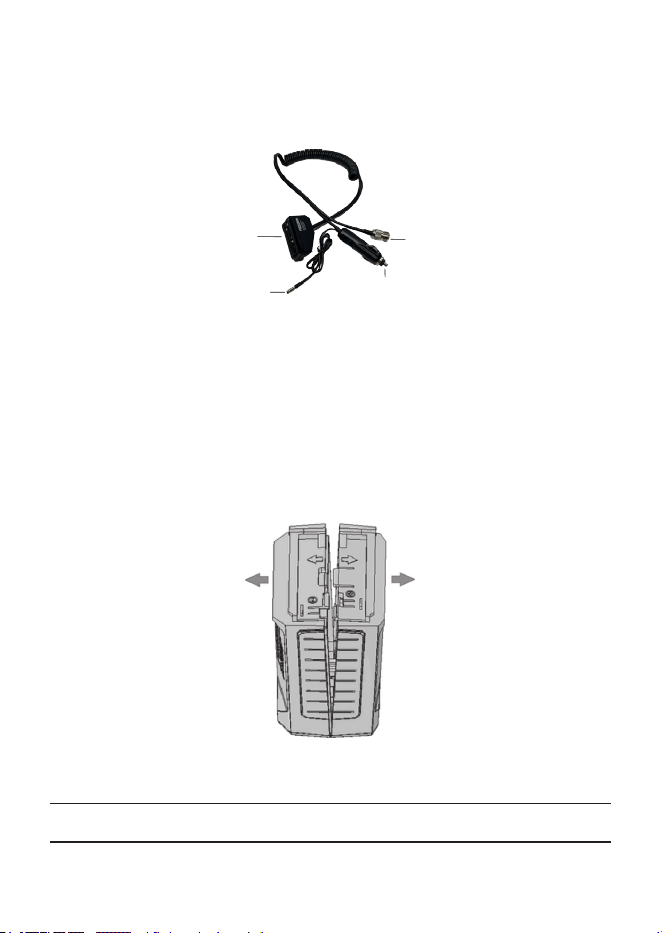
• In-Vehicle adapter connects the PRO538HHFM to the vehicle’s
12V DC cigarette port
Connect to
PRO538HHFM Radio.
DC Power Plug:
Connect to DC12V Vehicle
Power (Cigarette) Jack.
External CB
Antenna Connector
Charge Plug:
Connect to Ni-MH
Battery Case.
VEHICLE ADAPTER
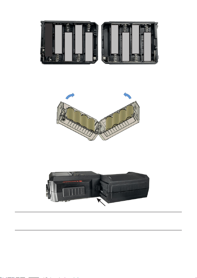
Rechargeable Ni-MH Batteries
The PRO538HHFM comes with a battery case for 8 AA Ni-MH batteries
(batteries not included).
1 Separate the two sides of the case by pulling them in the
directions noted on the shell.
2 Insert the 8 batteries according to the directions shown inside the
NiMH battery case.
CAUTION: Do not mix charged and uncharged batteries.
14
+ + +
+ + + +
+
3 Close the case. Align the bottom sides as shown and press the
two sides together.
4 Connect the battery case to the PRO538HHFM as shown.
PRO538HHFM
Ni-MH Battery Case
CAUTION: Do not attempt to charge Alkaline batteries in the Ni-MH
battery case as they may leak or catch re.

15
Charge Ni-MH Batteries
1 Verify that the Ni-MH batteries are inserted into the case.
2 Insert the In-Vehicle adapter’s charge plug into the Ni-MH battery
case. (See page 7 for the Ni-MH case location and page 13
for the location of the In-Vehicle adapter’s charge plug.)
3 When the plug is connected, the red LED on the battery case
lights up.
The charging current is 230mA (Nominal). When the radio is o, for
example, a discharged battery with a capacity of 2300mAh requires
about 10 hours of charging. If you charge the radio with the power ON,
the charging current will be reduced to about 80mA and requires about
16 hours of charging (it changes depending of the battery capacity and
condition). If you only want to charge the battery, turn o the radio’s
power.
You can remove the Ni-MH battery case from the radio to recharge
separately. Connect the radio to the Alkaline batteries/case or to the In-
Vehicle adapter to power the radio if needed.
CAUTION: Charging the battery for long periods of time will damage
the battery.
NOTE: The LED will not indicate when charging is complete.
NOTE: This plug is for charging only and is not intended to
power the radio. If you charge the battery while the battery case
is attached to the radio, the battery icon displayed on the radio
indicates always full while charging. The battery icon does not
indicate charging status; the charging is done directly to the
batteries without going through the radio.
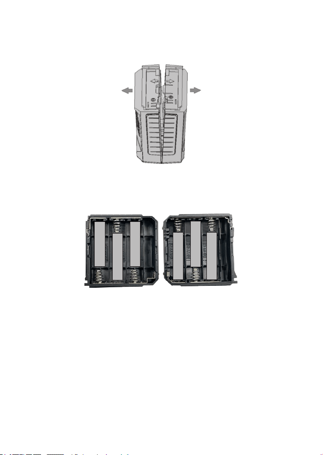
Alkaline Batteries
The PRO538HHFM comes with a battery case for 6 AA Alkaline
batteries (batteries not included).
16
1 Separate the two sides of the case by pulling them in the
directions noted on the shell.
2 Insert the 6 batteries according to the directions show inside the
alkaline battery case.
+
+
+
+
+
+
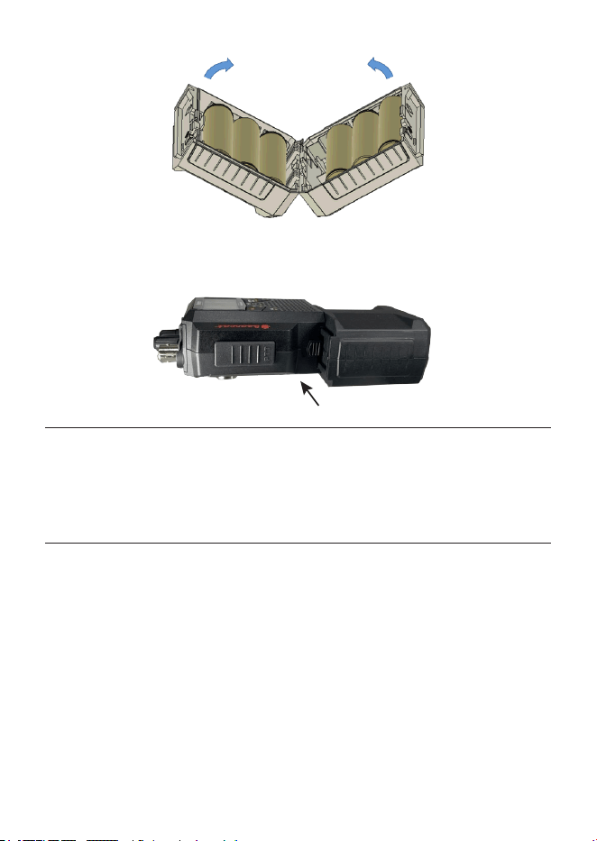
3 Close the case. Align the bottom sides as shown and press the
two sides together.
17
4 Connect the battery case to the PRO538HHFM as shown.
PRO538HHFM
ALK Battery Case
CAUTION: Mixing new and used batteries will reduce performance.
Do not charge Alkaline batteries as they may leak or catch re.
NOTE: If you do not use the radio for a long time, remove the
batteries from the battery case.
In-Vehicle Adapter
The PRO538HHFM comes with an In-Vehicle adapter to connect it to
the vehicle’s 12V DC cigarette plug.
1 Connect the In-Vehicle adapter to the PRO538HHFM.
2 Connect the In-Vehicle adapter’s 12V DC cigarette plug to your
vehicle.
18
CONNECT EXTERNAL SPEAKER AND
MICROPHONE
Your radio supports an external speaker and microphone. The external
speaker and microphone are sold separately.
EXTERNAL SPEAKER
Impedance 8 Ohms
Connect to EXT.SP. jack (⅛-in/3.5 mm)
Notes The internal speaker is disabled when an external
speaker is connected.
EXTERNAL MICROPHONE
Connect to MIC jack (2.5 mm Electret type)
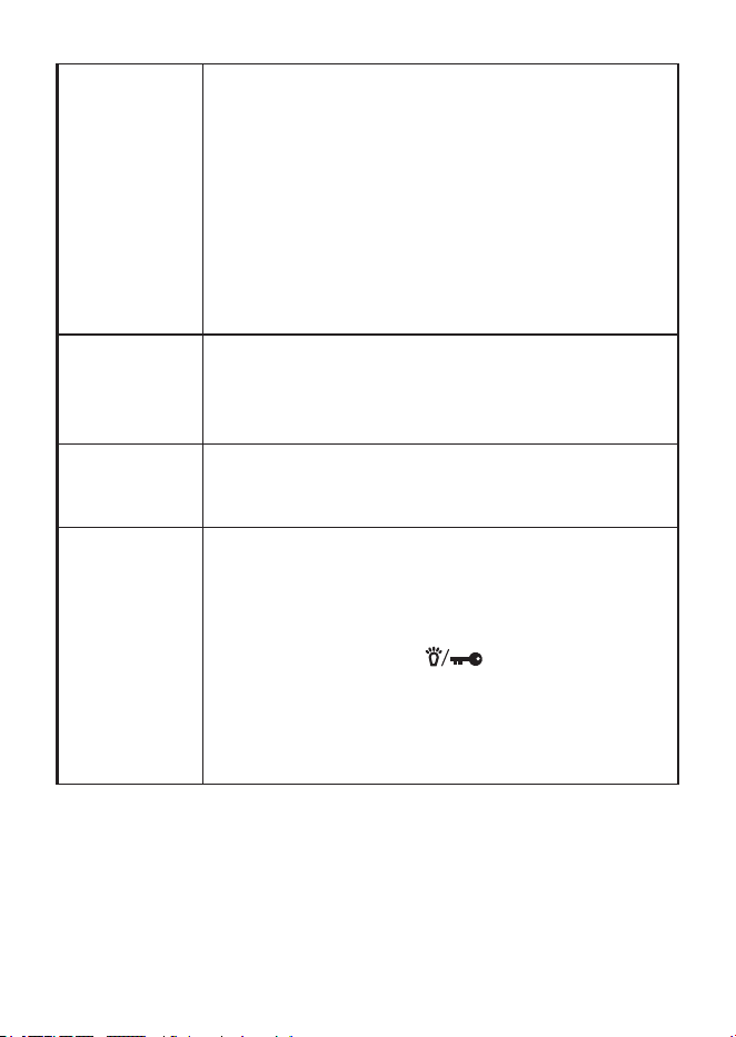
OPERATION
BASIC OPERATION
Turning the
radio on
Turn the VOL/SQ knob clockwise until it clicks and
the LCD display turns on.
Turning the
radio o
Turn the VOL/SQ knob counter-clockwise until it
clicks and the LCD display turns o.
Adjusting
Squelch
Turn the VOL/SQ knob counter-clockwise to open
squelch or clockwise to close it.
Select a mode
Press AM/FM key to select a mode as follows:
AM → FM → AM
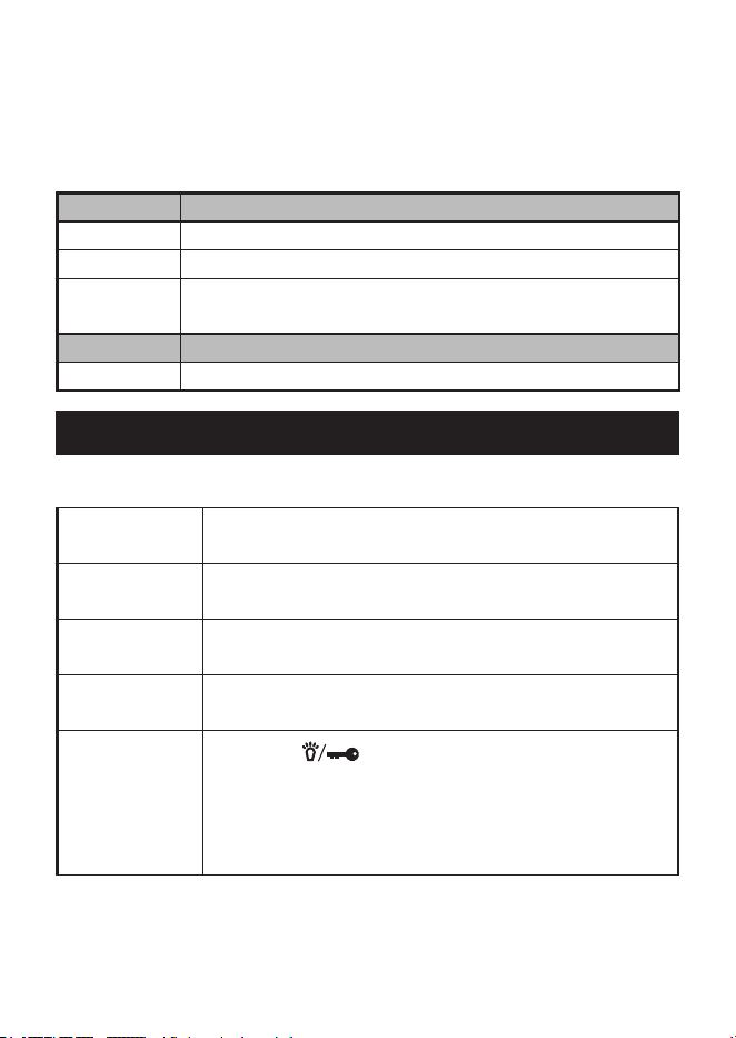
Turn backlight
on and o
Press the key to turn the LCD backlight on
for 10 seconds. Press it again while the backlight is
on to turn it o.
NOTE: Backlight does not support orange
letters on the keys.
19
Changing
backlight color
1 Press FUNC and COLOR key to enter
Backlight Setting mode.
2 Turn the CH/RF GAIN knob to select between
White and Amber. The LCD and keys ash.
Press FUNC or COLOR key again to set the
color and exit Backlight Setting mode.
NOTE: There is no time-out when in Backlight
Color mode.
NOTE: Backlight does not support the orange
letters on the keys.
Selecting a
channel
Turn the CH/RF GAIN knob to select a channel
(clockwise to increase the channel number or
counter-clockwise to decrease the channel
number).
Changing the
volume
After turning the radio on, turn the VOL/SQ knob
clockwise to increase the volume; turn it counter-
clockwise to decrease the volume.
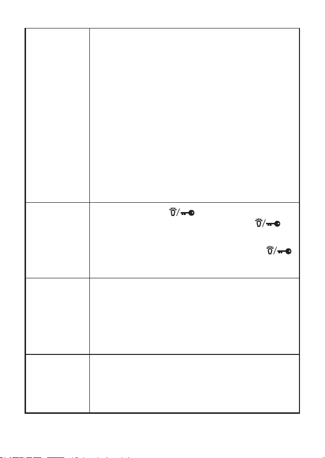
Setting Key
Beep (Default
= ON)
When key beep is on (default), the radio beeps
whenever a key is pressed or a knob is turned.
1 To change the key beep status, turn o the
PRO538HHFM.
2 Press and hold the key while turning
the radio on.
3 If the radio beeps, the key beep function is now
on. If the radio does NOT beep, the key beep
function is o.

20
Transmitting
1 Tune the radio to the channel you want to
transmit on, and listen to make sure the
channel is clear.
2 Press and hold the PTT. TX displays
3 Hold the microphone about 2 inches away from
your mouth and speak in a normal voice.
4 Release the PTT key to listen for a response.
Adjust RF
Gain
1 Press FUNC and ANL/GAIN to enter RF Gain
Setting mode. The GAIN bar blinks.
2 Turn the CH/RF GAIN knob to adjust Gain
levels (0 - 10). The selected level displays as a
7 segment number and the GAIN bar will blink.
The Gain level number reects in the number
of Gain bar boxes.
3 Press FUNC or ANL/GAIN again to store
the setting and return to the main operations
screen.
NOTE: RF Gain only applies to AM mode. No RF
Gain levels display in FM or WX modes.
21
Scanning
channels
NOTE: Before starting the scan, adjust the
position where Squelch closes on the
channel without a signal. If you turn the
knob all the way clockwise, the scan will
not stop unless the radio receives a strong
signal.
Press SCAN in AM or FM mode; the radio
scans the channels, stopping when it receives
a transmission. Scanning resumes if no signal
received for 3 seconds. Press SCAN again to stop
scanning.
Turn CH/RF GAIN knob while scanning to change
scan direction.
When stopped on a channel, turn CH/RF GAIN
knob to resume scanning.
Lock keys
to prevent
accidental
activation.
Press and hold the key to activate key lock;
the Lock icon displays. Only the PTT and
keys and the VOL/SQ knob are active.
With Key Lock activated, press and hold the
key to deactivate key lock; the Lock icon goes away
and all keys are now active.
Go to Instant
Channel 9/19
Press 9/19 from any channel (rst press): Goes to
CH 9. 9 displays in the Channel Indicator.
Second press: Goes to CH 19. 19 displays in the
Channel Indicator.
Third press: Returns to original channel. That
channel number displays in the Channel Indicator.
Select
Transmit
Power Level
Press FUNC and then press PWR H/L. The power
level alternates between High and Low. The
appropriate icon displays on the screen.
Power setting cannot be changed while in WX
mode; HI and LO icons will not display.

22
EMERGENCY OPERATION
The PRO538HHFM provides instant access to emergency channels 9
and 19. Press 9/19 DUAL once for channel 9; press it twice for channel
19. Press 9/19 DUAL a third time to return to the original channel.
NOTE: FCC rules reserve Channel 9 for motorist assistance and
other emergency communications. Channel 9 should only be used
in situations where there is immediate danger to the safety of
individuals or the protection of property.
Make sure you have read and understood part 95 of the FCC rules
and regulations before using the transmitter.
DUAL WATCH
Dual Watch lets you monitor two channels alternately for incoming
transmissions. When a transmission is detected on one of those
channels, the radio stays on that channel.
Programming Dual Watch Channels
1 Turn the CH/RF GAIN knob to select a channel.
2 Press the FUNC key and then press and hold the DUAL key to
enter Dual Watch (DW) programming mode. DW displays and
ashes.
3 Turn the CH/RF GAIN knob to select the second channel.
4 Press DUAL to assign the two channels to DW mode. DW stops
ashing and stays steady on; a conrmation tone sounds.
5 DW mode starts immediately. Press any key (except ANL, ,
AM/FM, and FUNC keys) to exit Dual Watch mode.
AUTOMATIC NOISE LIMITER
Automatic Noise Limiter (ANL) suppresses white noise.

23
1 In AM mode, press ANL to turn it on. The ANL icon displays when
this function is active.
2 Press ANL again to turn o this function.
NOTE: ANL does not function when the radio is in FM or WX mode.
WEATHER
The PRO538HHFM accesses 10 weather channels.
1 Press FUNC and then WX to access WX mode. The WX icon and
the current weather channel display.
2 Select a dierent weather channel by turning the channel knob.
3 Press AM/FM or 9/19 to return to normal CB operation. The WX
icon disappears.
NOTE: Squelch is always open in Weather mode, so using the
Squelch knob to adjust squelch will not work.
MAINTENANCE
Clean the unit with a damp cloth only; never use harsh chemicals.
TROUBLESHOOTING
If your radio is not performing to your expectations, please try these
simple steps. If these steps don’t solve your problem, visit the Uniden
website (www.uniden.com) for troubleshooting and FAQ information.
PROBLEM: THINGS TO TRY:
Radio won’t turn on
(no power)
– Check the polarity of the batteries in the
battery case.
– Check the fuse in the cigarette plug.
– Be sure the side latch is locked when you
install the In-Vehicle adapter.

24
Poor reception
– Be sure that the transmitting and receiving
radios match (AM-AM or FM-FM).
– CB radio waves are extremely attenuated
in a car so Uniden does not recommend
using the whip (rubber) antenna in the car.
– When using the radio in a car, be sure to
use an external antenna mounted on the
outside of the car.
– Check the RF Gain setting (see page
20).
– CB radios are easy to pick up noise from
computer-related equipment and power
lines, so keep the radio as far away from
these objects as possible.
Background noise
Try turning on ANL. The audio level is slightly
reduced but the noise can be attenuated (see
page 22).
Weak transmission
– Make sure the whip antenna and the
outside antenna are not connected at the
same time.
– Check transmission power settings (see
page 21).
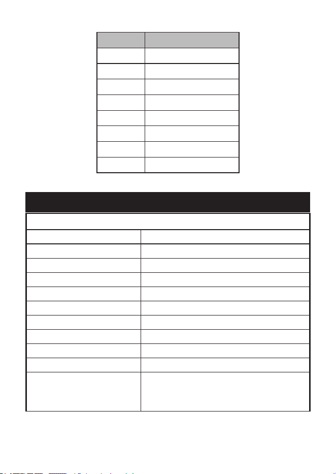
CB OPERATION
CB Communication Codes
The “10” code allows you to communicate easier in noisy
environments. The following table lists some of the most common
codes and their meanings.

25
CODE MEANING
10-1 Receiving poorly
10-2 Receiving well
10-3 Stop transmitting
10-4 OK - Understood
10-6 Busy - Stand By
10-7 Out of service - Leaving air
10-8 In service - Subject to call
10-9 Please repeat
10-10 Transmission completed - Standing by
10-13 Road advice - Weather conditions
10-20 What is your location?
10-33 Emergency trac
10-36 Exact time
10-41 Switch to channel
10-62 Cannot receive - use phone
10-70 Fire at __________
10-200 Police needed at __________
SERVICE AND REPAIR INFORMATION
• Save your purchase receipt for proof of warranty.
• When ordering parts, it is important to specify the correct model
number of this radio (PRO538HHFM).
• It is the user’s responsibility to make sure the radio is operating in
accordance with the FCC Citizens Radio Service regulations at all
times.

26
FREQUENCY LISTS
CB CHANNEL FREQUENCY LIST
CH NO. FREQ. (MHZ)
1 26.965
2 26.975
3 26.985
4 27.005
5 27.015
6 27.025
7 27.035
8 27.055
9 27.065
10 27.075
11 27.085
12 27.105
13 27.115
14 27.125
15 27.135
16 27.155
17 27.165
18 27.175
19 27.185
20 27.205
21 27.215
22 27.225

27
CH NO. FREQ. (MHZ)
23 27.255
24 27.235
25 27.245
26 27.265
27 27.275
28 27.285
29 27.295
30 27.305
31 27.315
32 27.325
33 27.335
34 27.345
35 27.355
36 27.365
37 27.375
38 27.385
39 27.395
40 27.405
WEATHER CHANNEL FREQUENCY LIST
CH NO. FREQ. (MHZ)
WX01 162.550
WX02 162.400
28
CH NO. FREQ. (MHZ)
WX03 162.475
WX04 162.425
WX05 162.450
WX06 162.500
WX07 162.525
WX08 161.650
WX09 161.775
WX10 163.275
SPECIFICATIONS
GENERAL
Channels 40 CB, 10 Weather
Mode CB AM/FM, Weather FM
Frequency Range 26.965 to 27.405 MHz
Frequency Control Phase Locked Loop (PLL) synthesizer
Frequency Tolerance ±0.005%
Operating Temperature -22ºF to +140ºF (-30ºC to +60ºC)
Storage Temperature -40ºF to +158ºF (-40ºC to +70ºC)
Microphone Electret Type built in
Antenna Impedance 50 ohms, unbalanced
Internal Speaker 8Ω, 28mmØ 1W
Input Voltage Vehicle Adapter: 13.8V DC
Ni-MH: 9.6V (8 AA batteries)
Alkaline: 9V (6 AA batteries)

29
Current Drain
TX: AM Max. Modulation: 1350mA
FM Max. Deviation: 960mA
RX: CB @ Squelch Close: 75mA
WX: 110mA
Size 2.5 W x 5.22 H x 1.5 D in (63.5 W x
135.2 H x 38 D mm)
Weight Approx. 7.9 oz. (225 g) with empty
alkaline battery case attached
Fuse rating (in cigarette
plug)
250V 2A Fast Acting 6x30mm
Charge Current 230mA @13.8V Radio = OFF
TRANSMITTER
Power Output 4 Watts
Frequency Tolerance +/– 0.002%
Hum and Noise > 40dB
Spurious Harmonics
Emission
–70dBc
RECEIVER
Usable Sensitivity
CB AM @10dB S/N
CB FM @12dB SINAD
WX FM @12dB SINAD
–110dBm
–114dBm
–120dBm
I.F. Frequency Double Conversion Superheterodyne
1st - 10.695 MHz
2nd - 455 kHz
Squelch Sensitivity Threshold: –117dBm/Tight: –47dBm
Audio Output Power 1W Nominal
Specications and features are subject to change without notice.

30
FCC PART 15 AND ISED COMPLIANCE
Changes or modications not expressly approved by the party
responsible for compliance could void the user’s authority to operate
the equipment.
Les changements ou modications qui ne sont pas expressément
approuvés par la partie responsable de la conformité peuvent annuler
l’autorité de l’utilisateur à utiliser l’équipement.
FCC PART 15 COMPLIANCE
This device complies with Part 15 of the FCC rules. Operation is
subject to the following two conditions: (1) This device may not cause
harmful interference, and (2) this device must accept any interference
received, including interference that may cause undesired operation.
Changes or modications not expressly approved by the party
responsible for compliance could void the user’s authority to operate
the equipment.
NOTE: This equipment has been tested and found to comply with
the limits for a Class B digital device, pursuant to Part 15 of the
FCC Rules.
These limits are designed to provide reasonable protection against
harmful interference in a residential installation.
This equipment generates, uses, and can radiate radio frequency
energy, and if not installed and used in accordance with the
instructions, may cause harmful interference to radio communications.
However, there is no guarantee that interference will not occur in a
particular installation.
If this equipment does cause harmful interference to radio or television
reception, which can be determined by turning the equipment o and
on, the user is encouraged to try to correct the interference by one or
more of the following measures:

31
• Reorient or relocate the receiving antenna.
• Increase the separation between the equipment and receiver.
• Connect the equipment into an outlet on a circuit dierent from
that to which the receiver is connected.
• Consult the dealer or an experienced radio/TV technician for help.
CONFORMITÉ À L’ARTICLE 15 DE LA FCC
Cet appareil est conforme à l’article 15 des règlementss de la FCC.
Son fonctionnement est soumis aux deux conditions suivantes : (1) cet
appareil ne doit pas causer d’interférences nuisibles, et (2) cet appareil
doit accepter toute interférence reçue, y compris les interférences
pouvant causer un fonctionnement indésirable.
Les changements ou modications qui ne sont pas expressément
approuvés par la partie responsable de la conformité peuvent annuler
votre droit d’utiliser l’équipement.
Remarque : Cet équipement a été testé et déclaré conforme aux
limites d’un appareil numérique de classe B, conformément à
l’article 15 des règlements de la FCC.
Les limites sont conçues pour fournir une protection raisonnable contre
les interférences nuisibles dans une installation résidentielle.
Cet équipement génère, utilise et peut émettre de l’énergie de
fréquence radio, et s’il n’est pas installé et utilisé conformément
aux instructions, il peut causer des interférences nuisibles aux
communications radio. Cependant, il n’y a aucune garantie que des
interférences ne se produiront pas dans une installation particulière.
Si cet équipement provoque des interférences nuisibles à la réception
de la radio ou de la télévision, ce qui peut être déterminé en éteignant
et en allumant l’équipement, l’utilisateur est encouragé à essayer de
corriger les interférences par une ou plusieurs des mesures suivantes :
• Réorienter ou déplacer l’antenne de réception.

32
• Augmentez la distance entre l’équipement et le récepteur.
• Connecter l’équipement à une prise sur un circuit diérent de celui
auquel le récepteur est connecté.
• Consulter le revendeur ou un technicien radio/TV expérimenté
pour obtenir de l’aide.
FCC AND ISED STATEMENT
This device meets the FCC and ISED RF Exposure Requirements
when used in a portable or mobile/xed application. For portable
applications, this device meets the FCC and ISED RF Exposure
requirements ONLY when used:
• With the antenna provided with this unit.
• With the Body-Worn and Audio accessories provide by, or
approved by, Uniden America Corporation.
• At a 50% Push-To-Talk (PTT) duty cycle. When operating this
device using the PTT pushbutton, do not operate (transmit) the
device more than 50% of the time during a conversation.
For mobile/xed applications, this device meets the FCC and ISED RF
Exposure requirements ONLY when:
• The antenna used for this device is properly installed and
maintained to provide a separation distance of at least 43 cm (17
Inches) from all persons and must not be collocated or operated
with any other transmitter.
• The user or users DO NOT transmit if any person is closer than
the distance indicated. While a 0 dBi gain antenna is normal for a
typical installation, the above limit applies to any antenna with up
to 3 dBi gain.
Cet appareil répond aux exigences d’exposition aux RF de la FCC et
de l’ISED lorsqu’il est utilisé dans une application portable ou mobile/
xe. Pour les applications portables, cet appareil répond aux exigences
de la FCC et de l’ISED en matière d’exposition aux RF UNIQUEMENT
lorsqu’il est utilisé :

33
• Avec l’antenne fournie avec cet appareil.
• Avec les accessoires corporels et audio fournis par, ou approuvés
par, Uniden America Corporation.
• Avec un cycle d’utilisation de 50% du bouton-poussoir PTT (Push-
To-Talk). Lorsque vous utilisez cet appareil à l’aide du bouton-
poussoir PTT, ne faites pas fonctionner (transmettre) l’appareil
plus de 50% du temps pendant une conversation.
Pour les applications mobiles/xes, cet appareil répond aux exigences
de la FCC et de l’ISED en matière d’exposition aux RF UNIQUEMENT
lorsque :
• L’antenne utilisée pour cet appareil est correctement installée
et entretenue pour assurer une distance de séparation d’au
moins 43 cm (17 pouces) de toute personne et ne doit pas être
colocalisée ou utilisée avec tout autre émetteur.
• L’utilisateur ou les utilisateurs NE DOIVENT PAS émettre si une
personne se trouve à une distance inférieure à celle indiquée.
Bien qu’une antenne à gain de 0 dBi soit normale pour une
installation typique, la limite ci-dessus s’applique à toute antenne
ayant un gain allant jusqu’à 3 dBi.
FCC 20 CM STATEMENT
This equipment complies with FCC radiation exposure limits set forth
for an uncontrolled environment. This equipment should be installed
and operated with a minimum distance of 20cm between the radio
and your body. This transmitter must not be co-located or operating in
conjunction with any other antenna or transmitter.
DÉCLARATION DE LA FCC 20 CM
Cet équipement est conforme aux limites d’exposition aux radiations
xées par la FCC pour un environnement non contrôlé. Cet
équipement doit être installé et utilisé avec une distance minimale
de 20 cm entre la radio et votre corps. Cet émetteur ne doit pas être
installé ou utilisé en conjonction avec une autre antenne ou un autre
émetteur.

34
ISED ANTENNA STATEMENT
This radio transmitter IC: 513C-UT433 has been approved by
Innovation, Science and Economic Development Canada to operate
with the antenna types listed below, with the maximum permissible
gain indicated. Antenna types not included in this list that have a gain
greater than the maximum gain indicated for any type listed are strictly
prohibited for use with this device.
The following antenna types can be used at the maximum 3 dBi gain
with a 50 Ohm impedance is required for each antenna type:
• Rubber
• Whip
• Fiberglass
ÉNONCÉ D’ANTENNE ISED
Cet émetteur radio IC : 513C-UT433 a été approuvé par Innovation,
Science et Développement économique Canada pour fonctionner avec
les types d’antennes listés ci-dessous, avec le gain maximum autorisé
indiqué Les types d’antennes non inclus dans cette liste qui ont un
gain supérieur au gain maximum indiqué pour tout type listé sont
strictement interdits d’utilisation avec cet appareil.
Les types d’antennes suivants peuvent être utilisés avec un gain
maximal de 3 dBi et une impédance de 50 Ohms est requise pour
chaque type d’antenne :
• Caoutchouc
• Fouet
• Fibre de verre
ONE-YEAR LIMITED WARRANTY
WARRANTOR: UNIDEN AMERICA CORPORATION (“Uniden”)

35
ELEMENTS OF WARRANTY: Uniden warrants, for one year, to the original retail
owner, this Uniden Product to be free from defects in materials and craftsmanship
with only the limitations or exclusions set out below.
WARRANTY DURATION: This warranty to the original user shall terminate
and be of no further eect 12 months after the date of original retail sale.
The warranty is invalid if the Product is (A) damaged or not maintained as
reasonable or necessary, (B) modied, altered, or used as part of any conversion
kits, subassemblies, or any congurations not sold by Uniden, (C) improperly
installed, (D) serviced or repaired by someone other than an authorized
Uniden service center for a defect or malfunction covered by this warranty, (E)
used in any conjunction with equipment or parts or as part of any system not
manufactured by Uniden, or (F) installed or programmed by anyone other than as
detailed by the owner’s manual for this product.
STATEMENT OF REMEDY: In the event that the product does not conform to
this warranty at any time while this warranty is in eect, warrantor will either,
at its option, repair or replace the defective unit and return it to you without
charge for parts, service, or any other cost (except shipping and handling)
incurred by warrantor or its representatives in connection with the performance
of this warranty. Warrantor, at its option, may replace the unit with a new or
refurbished unit. THE LIMITED WARRANTY SET FORTH ABOVE IS THE
SOLE AND ENTIRE WARRANTY PERTAINING TO THE PRODUCT AND IS
IN LIEU OF AND EXCLUDES ALL OTHER WARRANTIES OF ANY NATURE
WHATSOEVER, WHETHER EXPRESS, IMPLIED OR ARISING BY OPERATION
OF LAW, INCLUDING, BUT NOT LIMITED TO ANY IMPLIED WARRANTIES
OF MERCHANTABILITY OR FITNESS FOR A PARTICULAR PURPOSE. THIS
WARRANTY DOES NOT COVER OR PROVIDE FOR THE REIMBURSEMENT
OR PAYMENT OF INCIDENTAL OR CONSEQUENTIAL DAMAGES. Some
states do not allow this exclusion or limitation of incidental or consequential
damages so the above limitation or exclusion may not apply to you.
LEGAL REMEDIES: This warranty gives you specic legal rights, and you may
also have other rights which vary from state to state. This warranty is void outside
the United States of America.

36
PROCEDURE FOR OBTAINING PERFORMANCE OF WARRANTY: If, after
following the instructions in the owner’s manual you are certain that the Product
is defective, pack the Product carefully (preferably in its original packaging). The
Product should include all parts and accessories originally packaged with the
Product. Include evidence of original purchase and a note describing the defect
that has caused you to return it. The product should be shipped freight prepaid,
by traceable means, to warrantor at:
Uniden America Service
C/O Saddle Creek
743 Henrietta Creek Rd., Suite 100
Roanoke, TX 76262