PLANNING GUIDE
48" PROFESSIONAL
RANGES & BACKGUARDS
—
RGV2-485GD, RGV2-486GD, RGV2-486GL, RGV2-488,
RDV2-485GD, RDV2-486GD, RDV2-486GL, RDV2-488,
RGV2-485GD-N, RGV2-486GD-N, RGV2-486GL-N, RGV2-488-N,
RDV2-485GD-L, RDV2-486GD-L, RDV2-486GL-L, RDV2-488-L,
BGRV2-1248, BGRV2-3048, BGRV2-3048H models

CONTENTS
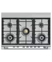
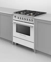
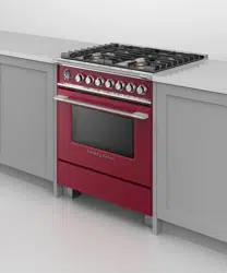
48" Professional Range
RGV2-485GD, RGV2-486GD, RGV2-486GL, RGV2-488
RDV2-485GD, RDV2-486GD, RDV2-486GL, RDV2-488
PAGE
in mm
Key Design Decisions 5 23
Ventilation Requirements 6 24
48" Professional Range
RGV2-485GD-N, RDV2-485GD-L
Product & Cavity Dimensions 7 25
Clearance Dimensions 8 26
Cavity Preparation 9 27
48" Professional Range
RGV2-486GD-N, RDV2-486GD-L
Product & Cavity Dimensions 10 28
Clearance Dimensions 11 29
Cavity Preparation 12 30
48" Professional Range
RGV2-486GL-N, RDV2-486GL-L
Product & Cavity Dimensions 13 31
Clearance Dimensions 14 32
Cavity Preparation 15 33

CONTENTS (continued)
48" Professional Range
RGV2-488-N, RDV2-488-L
PAGE
in mm
Product & Cavity Dimensions 16 34
Clearance Dimensions 17 35
Cavity Preparation 18 36
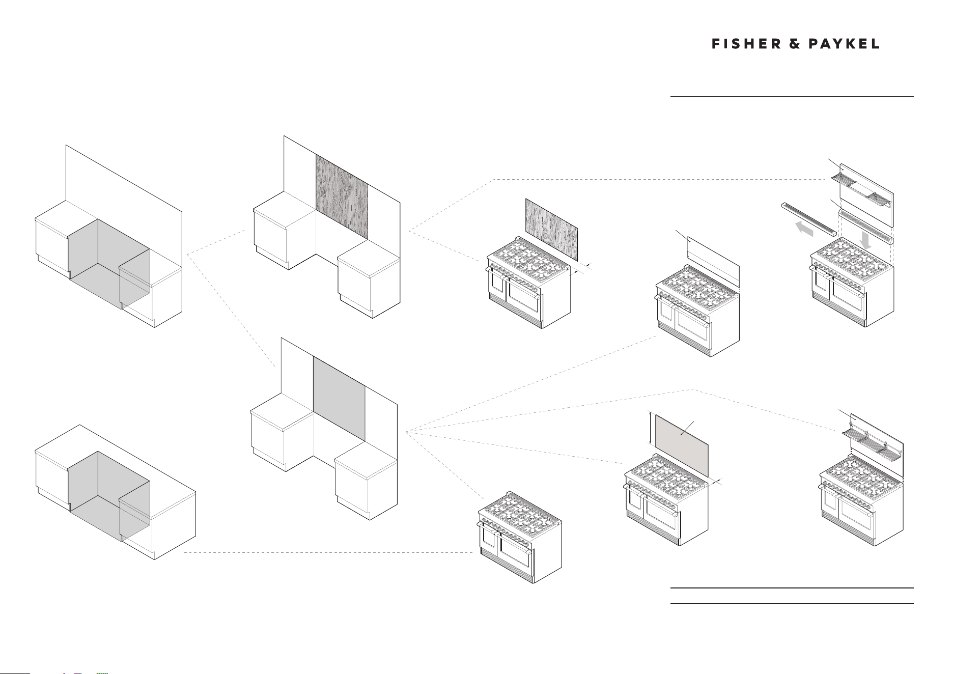
48" Professional Range Backguard
BGRV2-1248
Product Dimensions 19 37
48" Professional Range Backguard
BGRV2-3048
Product Dimensions 20 38
48" Professional Range Backguard
BGRV2-3048H
Product Dimensions 21 39

IMPERIAL
DATE: 24.04.2018
IMPORTANT: Throughout this guide, dimensions may vary by ±2mm (1/16'').
Read the installation guide for detailed information on installing the product.
For full installation instructions and specifications visit fisherpaykel.com
Model no:
RGV2-485GD, RGV2-486GD, RGV2-486GL, RGV2-488
RDV2-485GD, RDV2-486GD, RDV2-486GL, RDV2-488
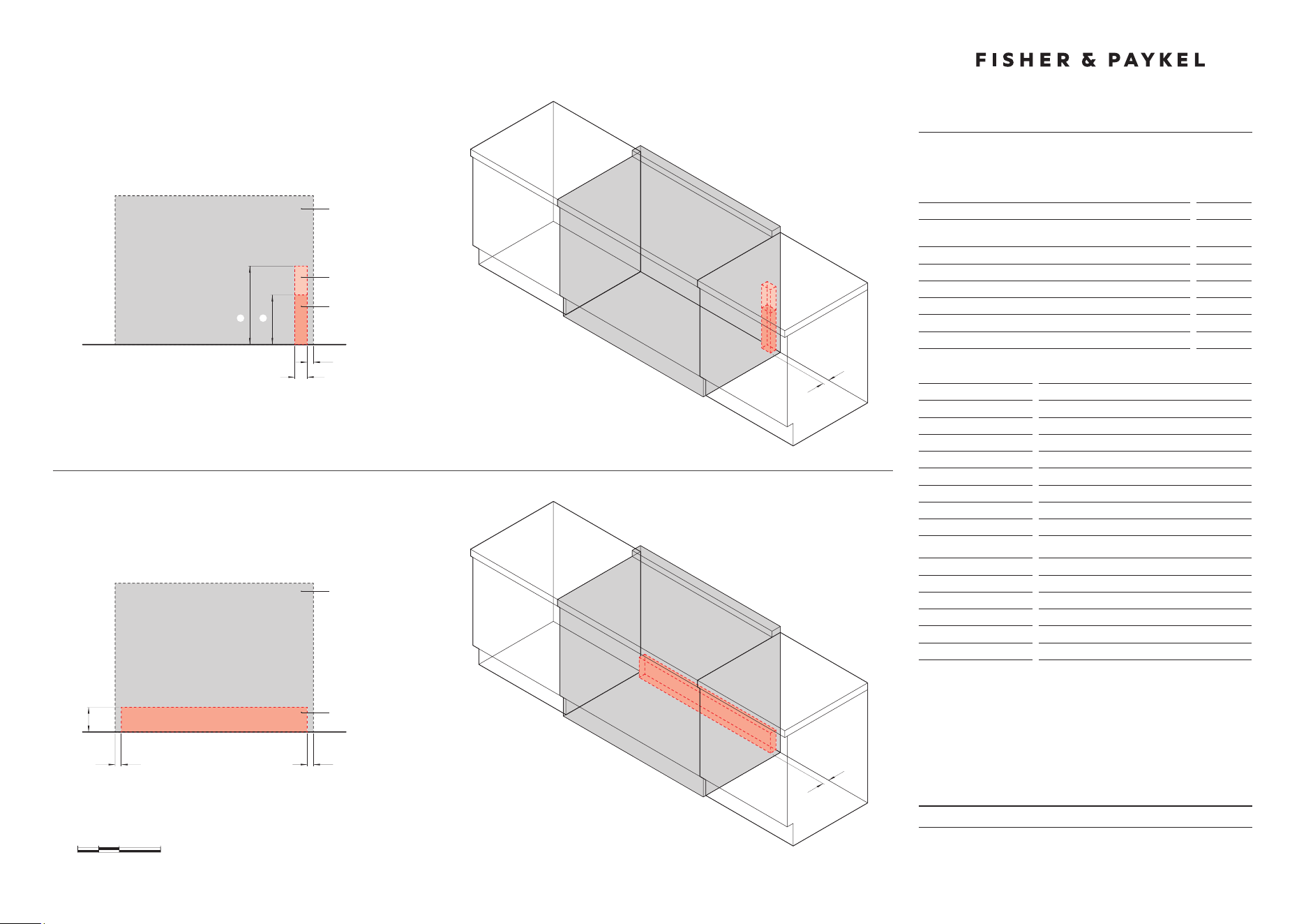
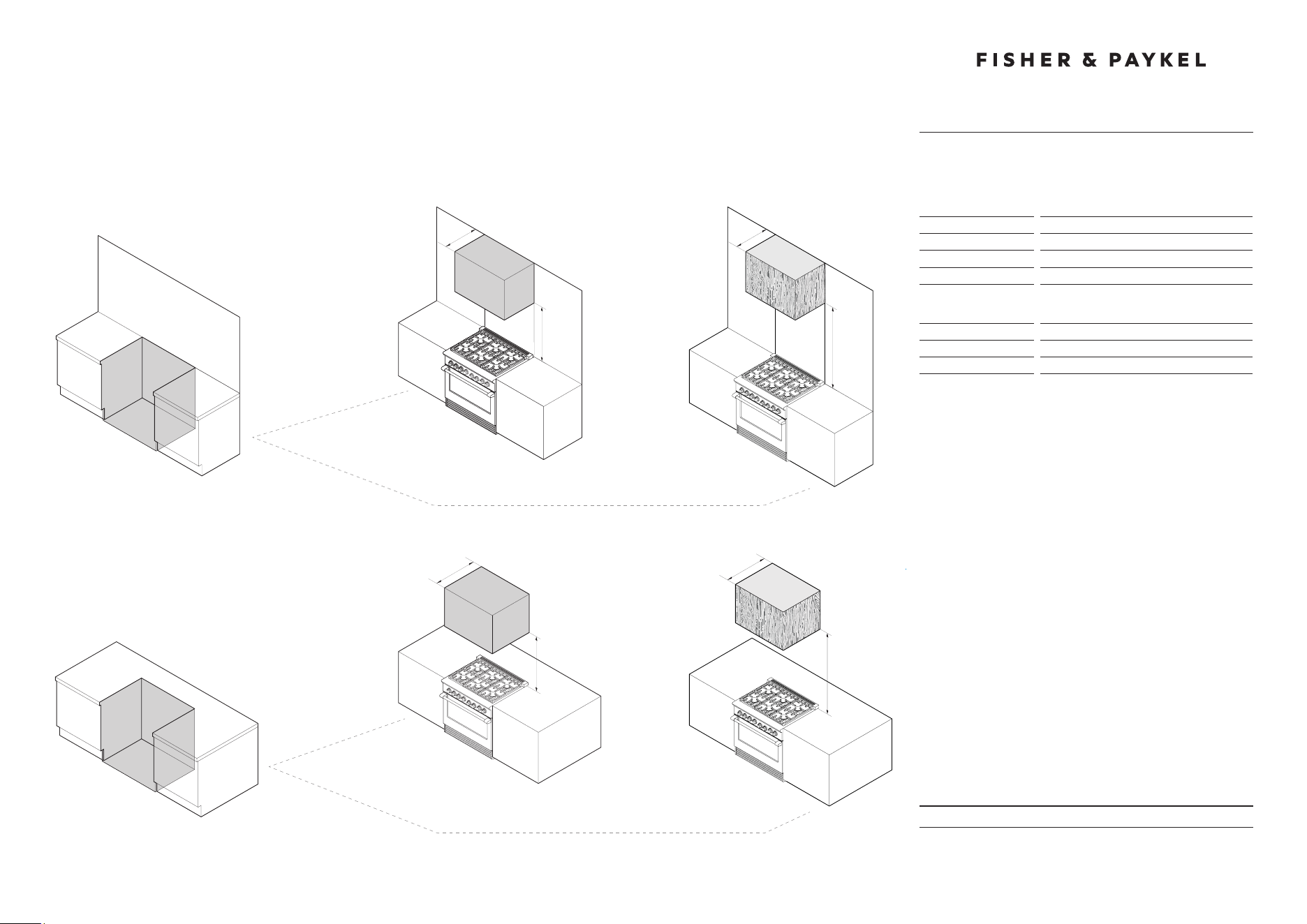
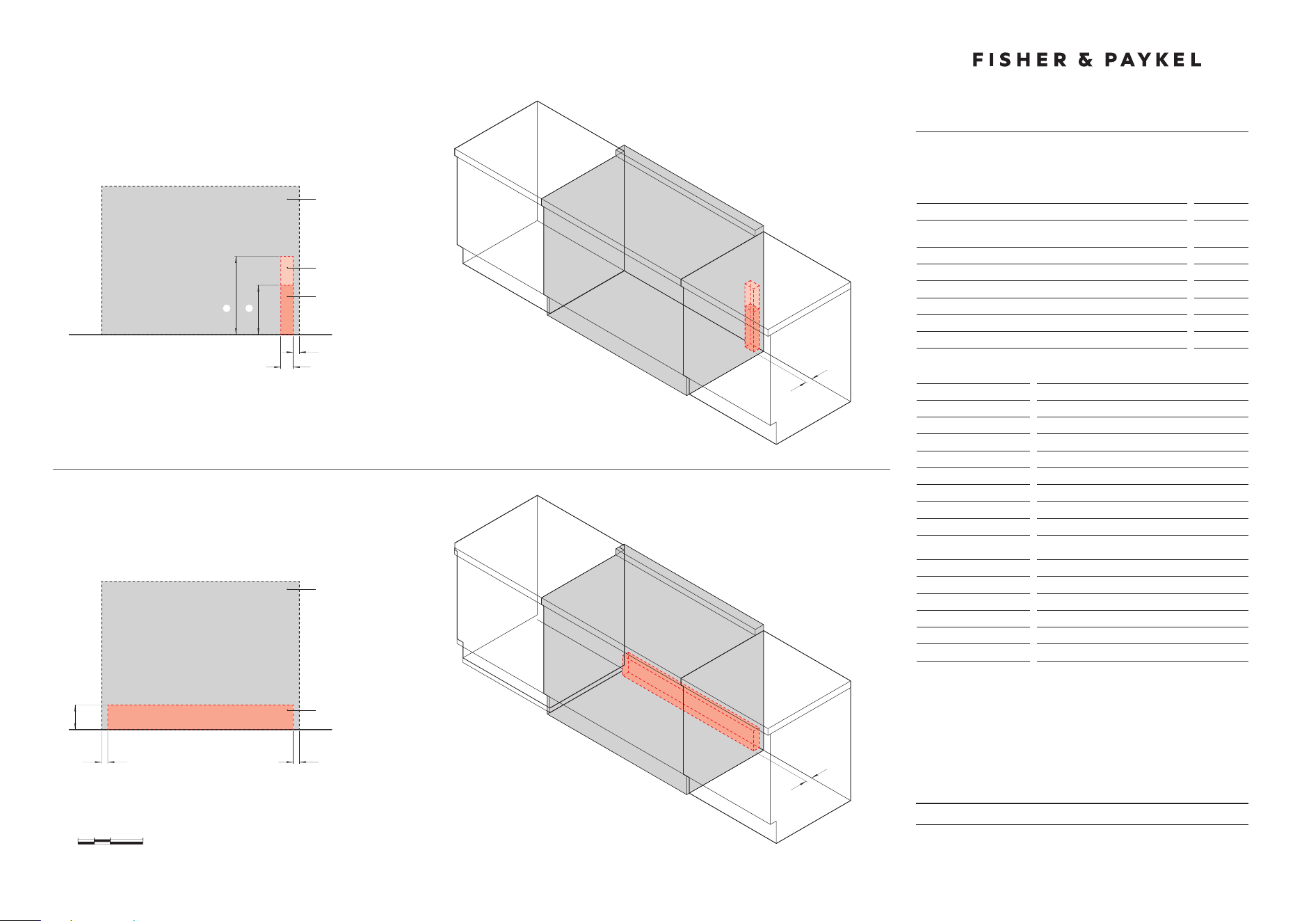
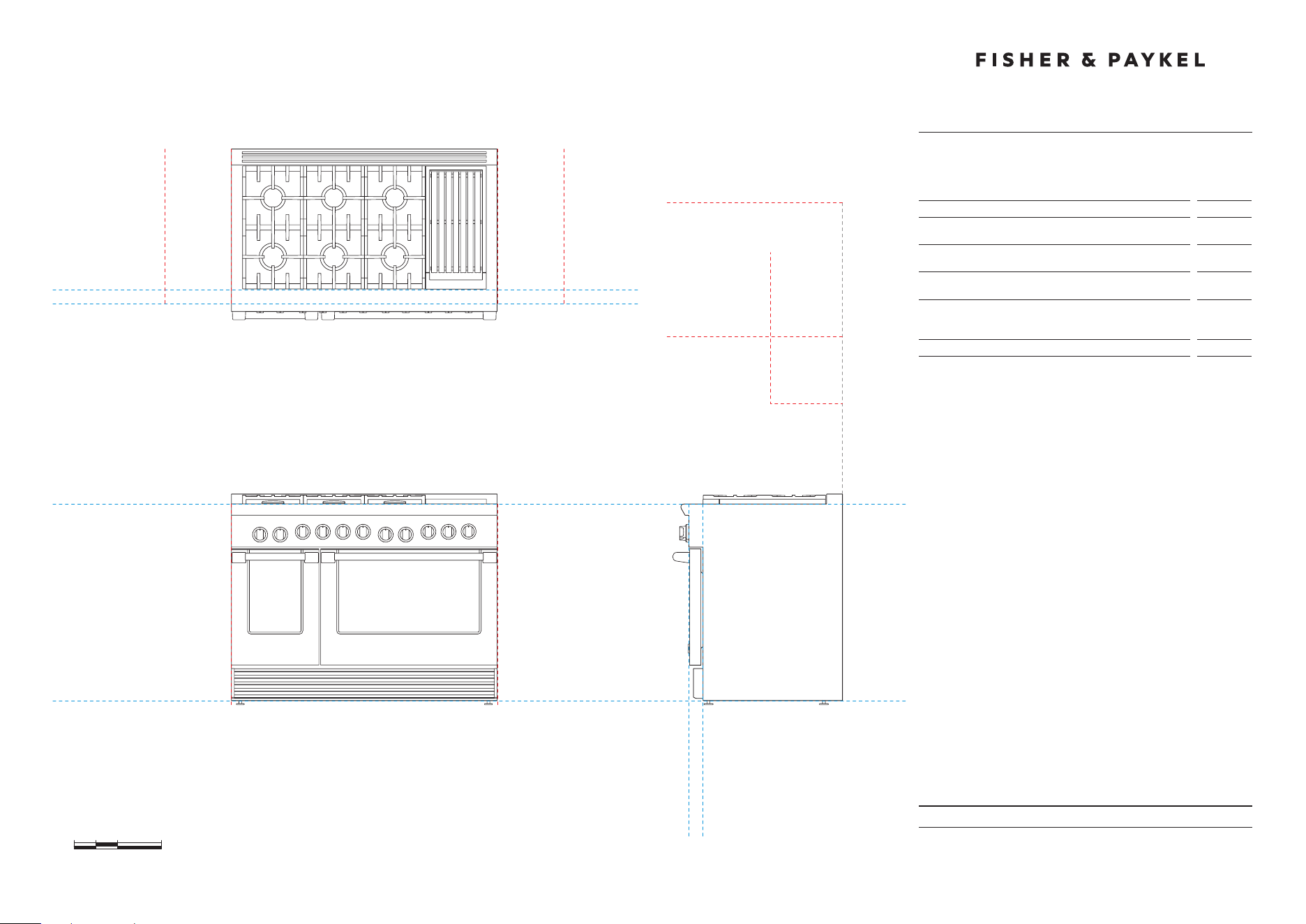
KEY DESIGN DECISIONS
48" Professional Range
INSTALL TYPE
1
WALL
ISLAND
REAR SURFACE
2
COMBUSTIBLE
NON COMBUSTIBLE
BACKGUARD OPTIONS
3
NO BACKGUARD
HIGH THICK BACKGUARD
WITH ANGLED TRIM
BGRV2-3048H
ANGLED TRIM
(Supplied with
backguard)
LOW THIN BACKGUARD
BGRV2-1248
NO BACKGUARD
MIN 6"
CLEARANCE
HIGH THIN BACKGUARD
BGRV2-3048
CUSTOM FABRICATED* BACKGUARD
*Fabricated from non combustible materials only
CUSTOM
BACKGUARD*
MAX 1/2"
MIN 30"

DATE: 24.04.2018
IMPORTANT: Throughout this guide, dimensions may vary by ±2mm (1/16'').
Read the installation guide for detailed information on installing the product.
For full installation instructions and specifications visit fisherpaykel.com
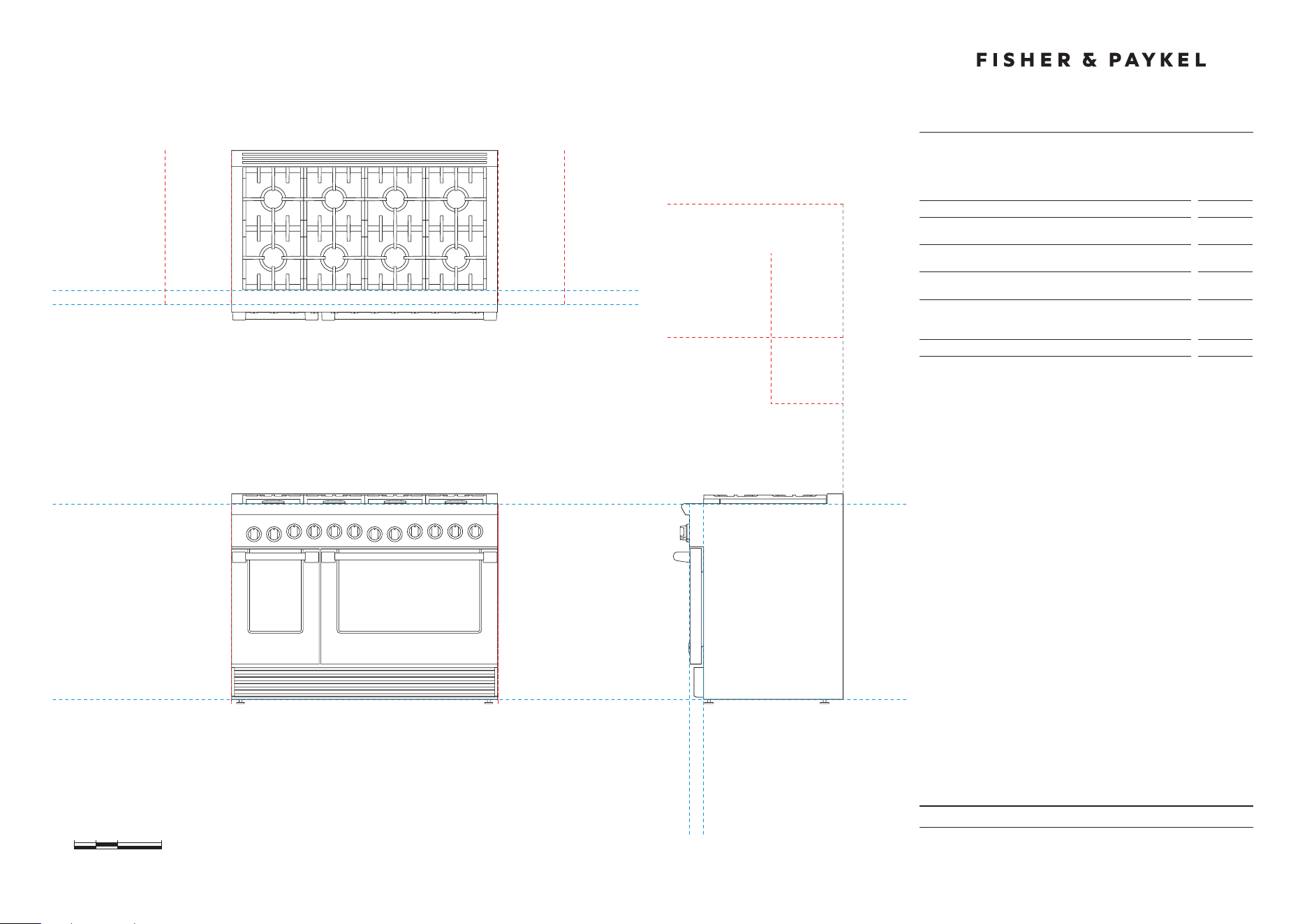
VENTILATION REQUIREMENTS
48" Professional Range
INSTALL TYPE
1
WALL
ISLAND
HOOD SURROUND MATERIAL
2
NON COMBUSTIBLE
23"
NON COMBUSTIBLE
MIN 30"
MAX 36"
MIN 30"
MAX 36"
30"
COMBUSTIBLE
COMBUSTIBLE
30"
MIN 36"
MIN 36"
23"
Model no:
RGV2-485GD, RGV2-486GD, RGV2-486GL, RGV2-488
RDV2-485GD, RDV2-486GD, RDV2-486GL, RDV2-488
Note: RGV2-366 illustrated but all dimensions apply to the above models
Specifications
Ventilation Unit
Wall Installation
Hood
23'' Deep x Unit Width
Blower
1200 CFM
Ventilation Unit
Island Installation
Hood
30'' Deep x Unit Width
Blower
1200 CFM
Note: A suitable hood must be installed above the range. The above indicates
the minimum blower capacity recommended for hood ventilation.
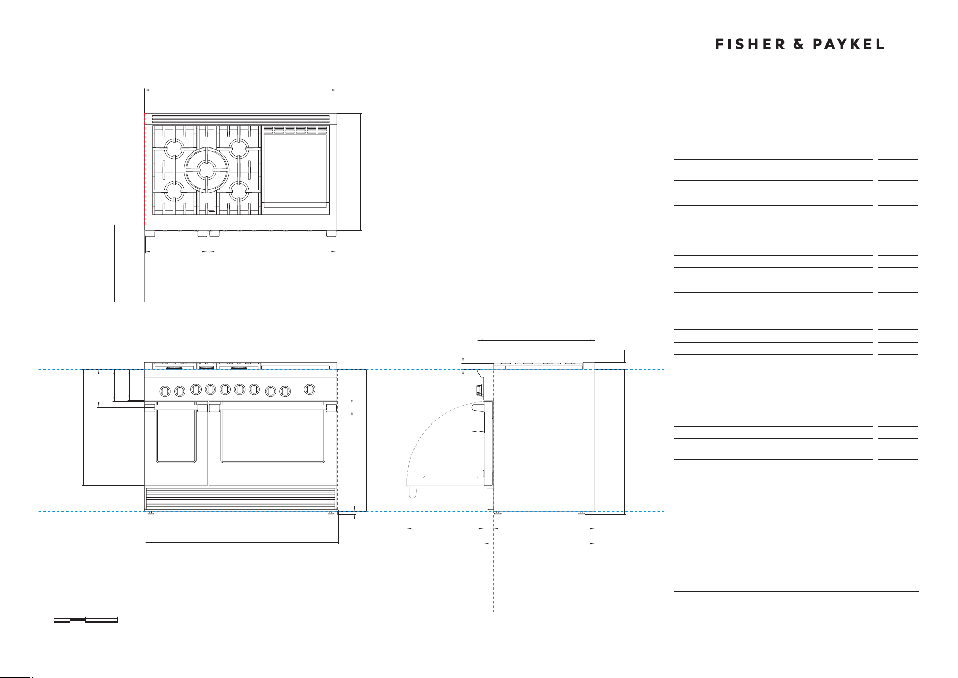
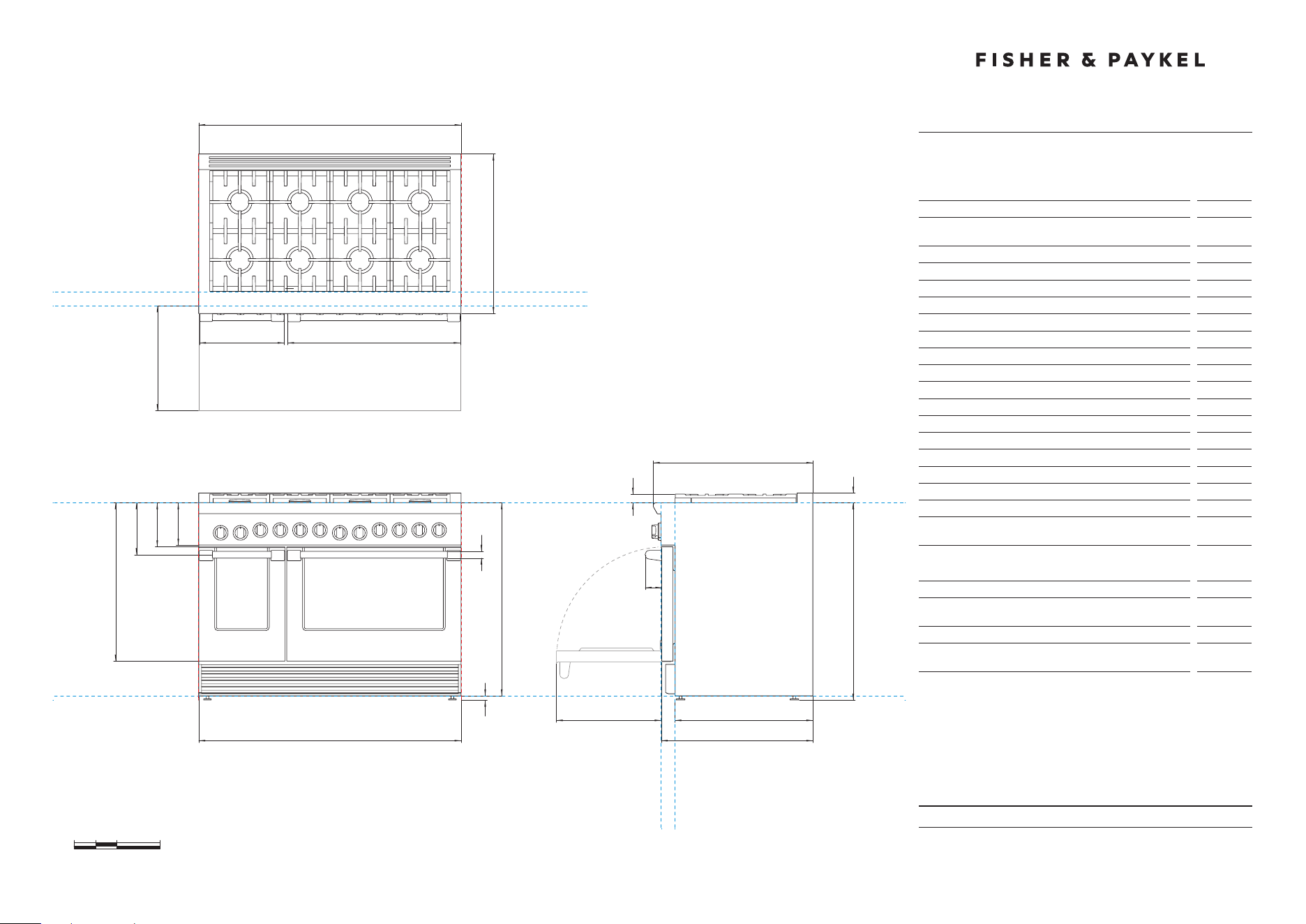
PRODUCT & CAVITY DIMENSIONS
48" Professional Range
DATE: 24.04.2018
IMPORTANT: Throughout this guide, dimensions may vary by ±2mm (1/16'').
Read the installation guide for detailed information on installing the product.
For full installation instructions and specifications visit fisherpaykel.com
INDICATES PRODUCT DATUM -------------------------------------------
0 5 10 20
inches
47 7/8''
B
29 1/8''
35 3/4'' -
36 3/4''
29 1/8''
47 7/8''
B
DATUM : BOTTOM OF CHASSIS
A
FRONT VIEW
PROFILE VIEW
C
m
K J I H
GF
l
DATUM :
TOP OF
COUNTERTOP
CABINET FACE FOR INSTALLATION
WITH PROJECTING CONTROL PANEL
CABINET FACE FOR INSTALLATION
WITH FLUSH CONTROL PANEL
CABINET FACE FOR
INSTALLATION WITH
PROJECTING CONTROL PANEL
CABINET FACE FOR
INSTALLATION WITH
FLUSH CONTROL PANEL
p
Dq
E
C
PLAN VIEW
on
q
r
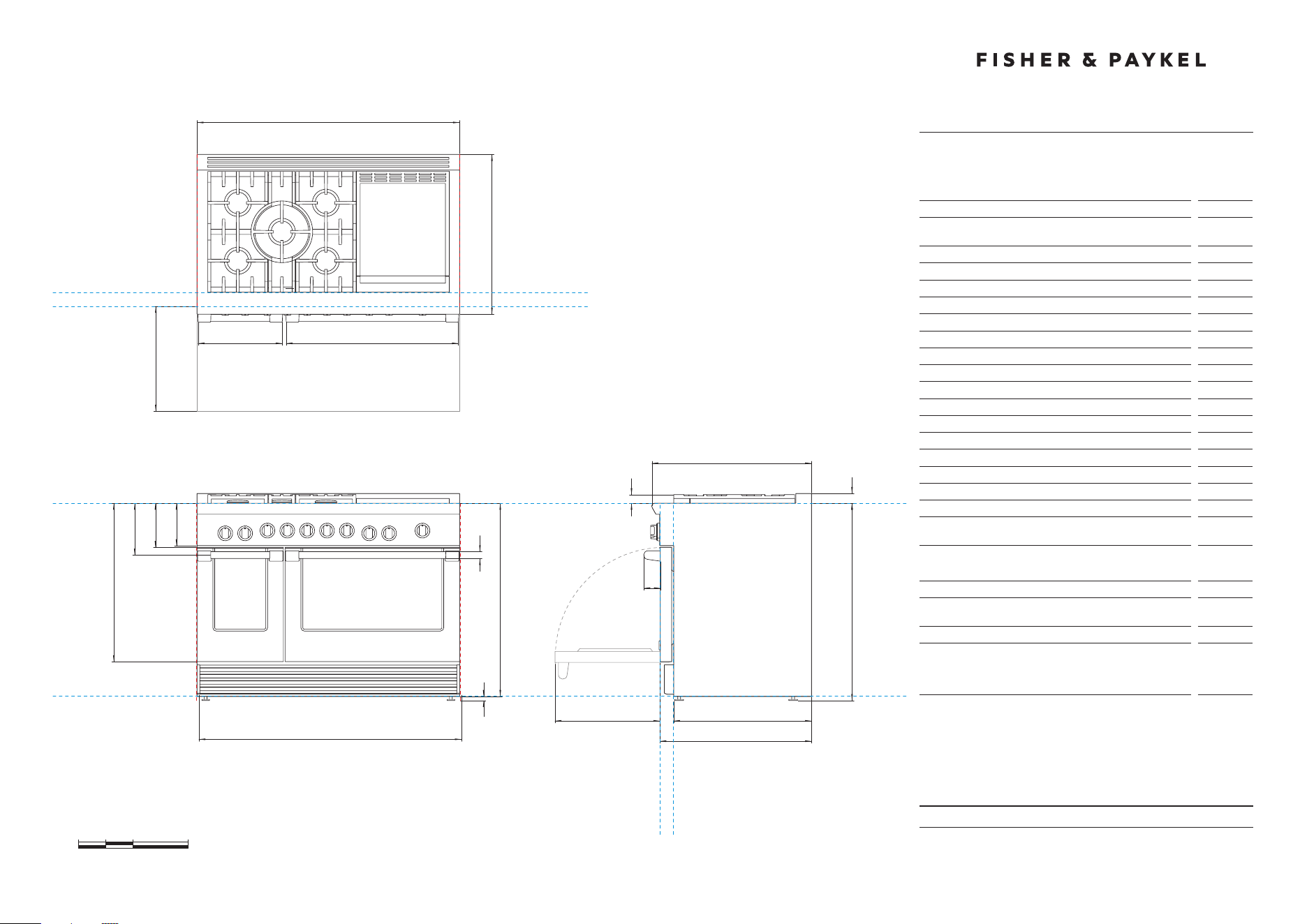
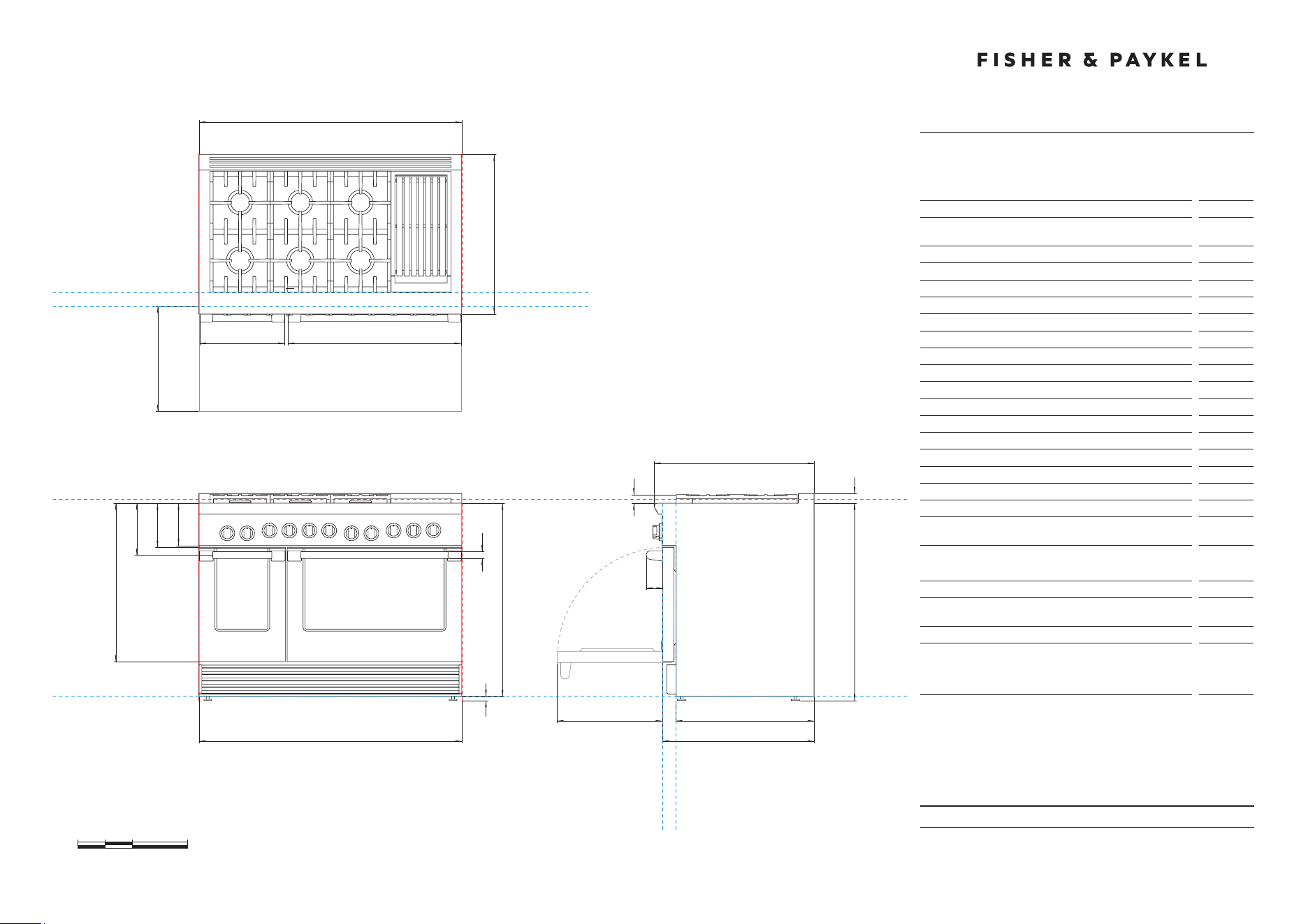
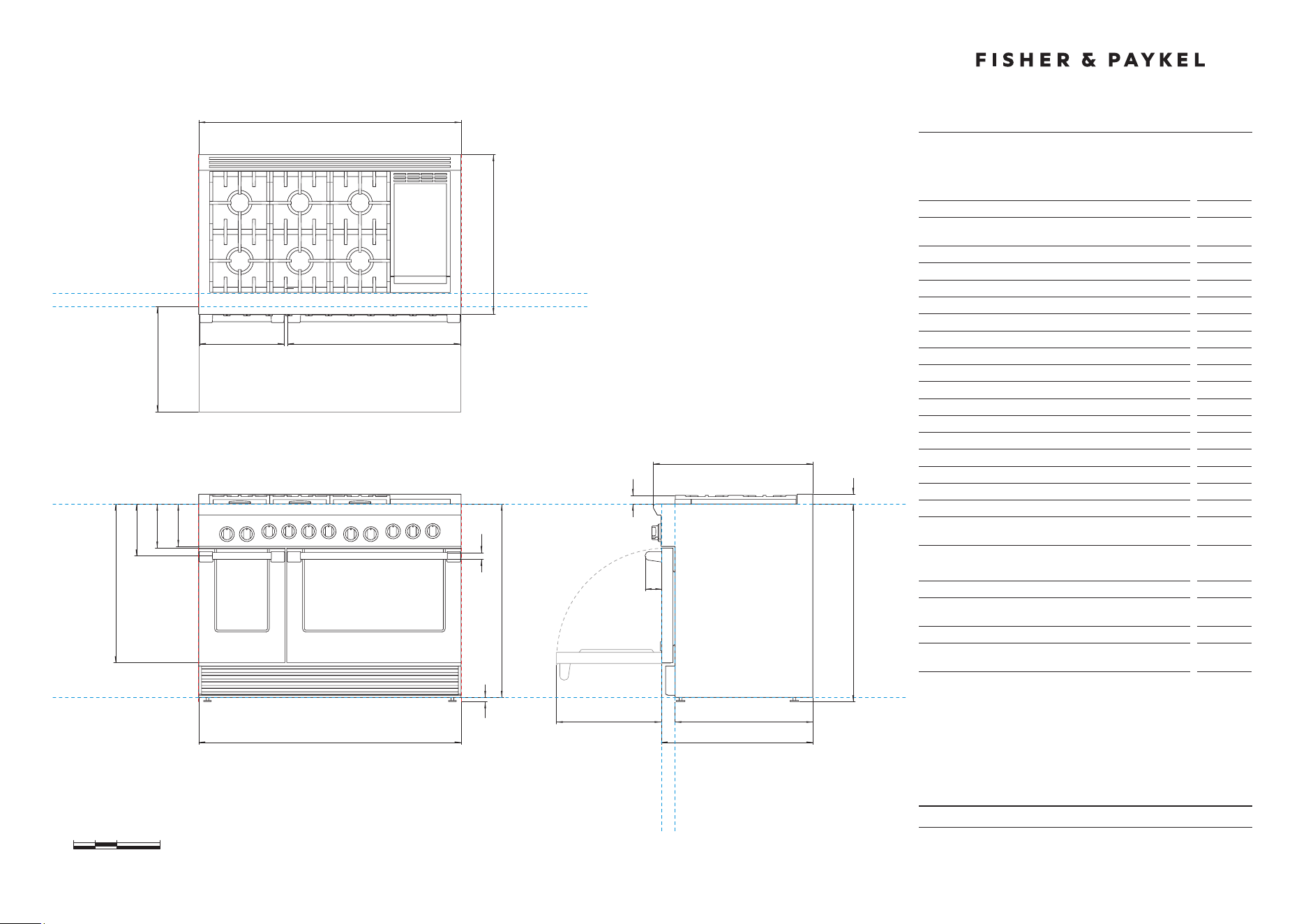
Model no:
RGV2-485GD-N, RGV2GD-485-L
RDV2-485GD-N, RDV2GD-485-L
Product Dimensions
in
A Overall height of range (from floor to cooktop,
excludinggrates and vent trim)
min 35 3/4''
max 36 3/4''
B Overall width of range
47 7/8''
C Overall depth of range (excluding handle and dials)
29 1/8''
D Depth from rear of chassis to cabinetry face - projecting
25 1/8''
E Depth from rear of chassis to cabinetry face - flush
27 11/16''
F Height from countertop to top of pan supports
1 9/16''
G Height from countertop to top of vent trim
1 3/4''
H Height from countertop to bottom of control panel
7 3/4''
I Height from countertop to top of door
8 1/16''
J Height from countertop to center of handle
9 7/16''
K Height from countertop to bottom of door
28 7/8''
L Height from countertop to bottom of chassis
35 1/4''
M Thickness of handles (not including standoffs)
1 1/4''
N Width of left handle (including standoffs)
15 1/16''
O Width of right handle (including standoffs)
31 1/2''
P Depth of handle (measured from front of door)
3 1/16''
Q Depth of open door to cabinetry face - flush
19 1/8''
R Adjustable feet height
min 1/2''
max 1 1/2''
Cavity Dimensions
in
Overall height of cavity
min 35 3/4''
max 36 3/4''
Overall width of cavity
min 48''
Overall depth of cavity for projecting control panel
Overall depth of cavity for flush control panel
max
25 1/8''
max
27 11/16''
DATE: 24.04.2018
IMPORTANT: Throughout this guide, dimensions may vary by ±2mm (1/16'').
Read the installation guide for detailed information on installing the product.
For full installation instructions and specifications visit fisherpaykel.com
INDICATES CABINETRY CLEARANCES --------------------------------
INDICATES PRODUCT DATUM -------------------------------------------
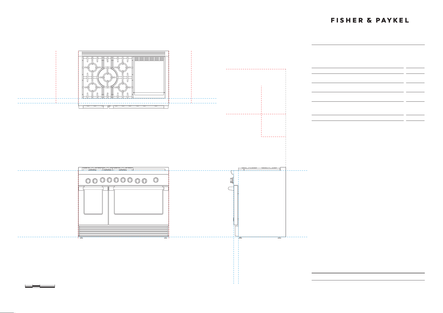
CLEARANCE DIMENSIONS
48" Professional Range
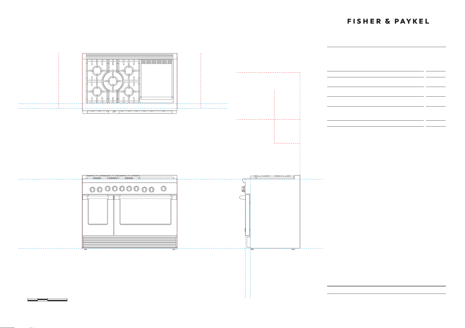
Model no:
RGV2-485GD-N, RGV2-485GD-L
RDV2-485GD-N, RDV2-485GD-L
Clearance Dimensions
in
A Minimum width of ventilation hood installed above range
- not shown*
48''
B Minimum vertical distance between countertop and cabinet
extending above counter
18''
C Minimum clearance from left and right edge of range to
nearest vertical combustible surface
12''
D Minimum clearance from cooking surface to:
– combustible surface centered above the cooking surface
– non-combustible surface centered above the cooking surface
54''
30''
E Maximum overall depth of overhead cabinetry
13''
0 5 10 20
inches
DATUM : BOTTOM OF CHASSIS
FRONT VIEW PROFILE VIEW
DATUM :
TOP OF COUNTERTOP
CABINET FACE FOR
INSTALLATION WITH
PROJECTING CONTROL PANEL
CABINET FACE FOR
INSTALLATION WITH
FLUSH CONTROL PANEL
PLAN VIEW
MINIMUM CLEARANCE:
COMBUSTIBLE SURFACE
MAXIMUM OVERALL DEPTH
OF OVERHEAD CABINETRY
MINIMUM CLEARANCE:
ADJACENT OVERHEAD CABINET
MINIMUM CLEARANCE:
NON-COMBUSTIBLE SURFACE
MINIMUM CLEARANCE:
NEAREST VERTICAL
COMBUSTIBLE SURFACE
CABINET FACE FOR INSTALLATION
WITH PROJECTING CONTROL PANEL
CABINET FACE FOR INSTALLATION
WITH FLUSH CONTROL PANEL
MINIMUM CLEARANCE:
NEAREST VERTICAL
COMBUSTIBLE SURFACE
MINIMUM CLEARANCE:
NEAREST VERTICAL
COMBUSTIBLE SURFACE
D
E
D
B
CC
DATE: 24.04.2018
IMPORTANT: Throughout this guide, dimensions may vary by ±2mm (1/16'').
Read the installation guide for detailed information on installing the product.
For full installation instructions and specifications visit fisherpaykel.com
CAVITY PREPARATION
48" Professional Range
G
RDV models
0 5 10 20
inches
Model no:
RGV2-485GD-N, RGV2-485GD-L
RDV2-485GD-N, RDV2-485GD-L
Location of Electrical and Gas Supply
in
A Depth of supply area (ie maximum protrusion of
gasconnection from wall)
2''
B Distance from right hand edge of range to supply area
1 1/2''
C (RGV) Height of electrical supply area (from floor)
19''
D (RGV) Height of gas supply area (from floor)
12''
E (RGV) Width of supply area
3''
F (RDV) Distance from left hand edge of range to supply area
1 1/2''
G (RDV) Height of electrical and gas supply area (from floor)
6''
Specifications
Electrical
RGV Models
Supply
120 VAC, 60Hz
Max. Current Draw
15 amp
Service
15 amp circuit
Electrical
RDV Models
Supply
120/240 VAC, 60Hz
Max. Current Draw
40 amp
Service
50 amp circuit
Gas – Natural
Connection
1/2” NPT Minimum 5/8” dia. flex line
Supply Pressure
Supply Pressure: 6” to 9” W.C.
Gas – LP
Connection
1/2” NPT Minimum 5/8” dia. flex line
Supply Pressure*
11” to 14” W.C.
A regulator is required at the LP source to provide a maximum pressure
of 14” W.C. to the range regulator.
F B
A
FINAL POSITION OF
RANGE AGAINST WALL
ELECTRICAL & GAS
RGV models
C D
E
B
A
FINAL POSITION OF
RANGE AGAINST WALL
ELECTRICAL
GAS
PRODUCT & CAVITY DIMENSIONS
48" Professional Range
DATE: 24.04.2018
IMPORTANT: Throughout this guide, dimensions may vary by ±2mm (1/16'').
Read the installation guide for detailed information on installing the product.
For full installation instructions and specifications visit fisherpaykel.com
INDICATES PRODUCT DATUM -------------------------------------------
0 5 10 20
inches
47 7/8''
B
29 1/8''
35 3/4'' -
36 3/4''
29 1/8''
47 7/8''
B
DATUM : BOTTOM OF CHASSIS
A
FRONT VIEW
PROFILE VIEW
C
m
K J I H
GF
l
DATUM :
TOP OF
COUNTERTOP
CABINET FACE FOR INSTALLATION
WITH PROJECTING CONTROL PANEL
CABINET FACE FOR INSTALLATION
WITH FLUSH CONTROL PANEL
CABINET FACE FOR
INSTALLATION WITH
PROJECTING CONTROL PANEL
CABINET FACE FOR
INSTALLATION WITH
FLUSH CONTROL PANEL
p
Dq
E
C
PLAN VIEW
on
q
r
Model no:
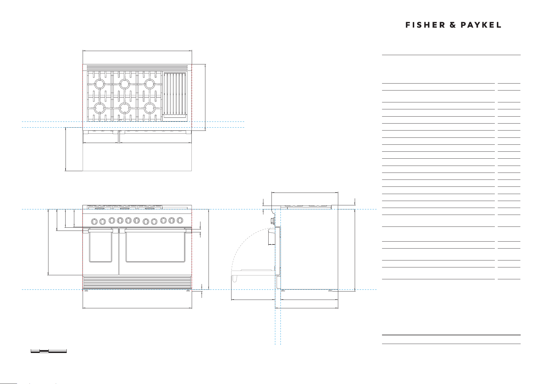
RGV2-486GD-N, RGV2-486GD-L
RDV2-486GD-N, RDV2-486GD-L
Product Dimensions
in
A Overall height of range (from floor to cooktop,
excludinggrates and vent trim)
min 35 3/4''
max 36 3/4''
B Overall width of range
47 7/8''
C Overall depth of range (excluding handle and dials)
29 1/8''
D Depth from rear of chassis to cabinetry face - projecting
25 1/8''
E Depth from rear of chassis to cabinetry face - flush
27 11/16''
F Height from countertop to top of pan supports
1 9/16''
G Height from countertop to top of vent trim
1 3/4''
H Height from countertop to bottom of control panel
7 3/4''
I Height from countertop to top of door
8 1/16''
J Height from countertop to center of handle
9 7/16''
K Height from countertop to bottom of door
28 7/8''
L Height from countertop to bottom of chassis
35 1/4''
M Thickness of handles (not including standoffs)
1 1/4''
N Width of left handle (including standoffs)
15 1/16''
O Width of right handle (including standoffs)
31 1/2''
P Depth of handle (measured from front of door)
3 1/16''
Q Depth of open door to cabinetry face - flush
19 1/8''
R Adjustable feet height
min 1/2''
max 1 1/2''
Cavity Dimensions
in
Overall height of cavity
min 35 3/4''
max 36 3/4''
Overall width of cavity
min 48''
Overall depth of cavity for projecting control panel
Overall depth of cavity for flush control panel
max
25 1/8''
max
27 11/16''

DATE: 24.04.2018
IMPORTANT: Throughout this guide, dimensions may vary by ±2mm (1/16'').
Read the installation guide for detailed information on installing the product.
For full installation instructions and specifications visit fisherpaykel.com
INDICATES CABINETRY CLEARANCES --------------------------------
INDICATES PRODUCT DATUM -------------------------------------------
CLEARANCE DIMENSIONS
48" Professional Range
0 5 10 20
inches
Model no:
RGV2-486GD-N, RGV2-486GD-L
RDV2-486GD-N, RDV2-486GD-L
Clearance Dimensions
in
A Minimum width of ventilation hood installed above range -
not shown*
48''
B Minimum vertical distance between countertop and cabinet
extending above counter
18''
C Minimum clearance from left and right edge of range to
nearest vertical combustible surface
12''
D Minimum clearance from cooking surface to:
– combustible surface centered above the cooking surface
– non-combustible surface centered above the cooking surface
54''
30''
E Maximum overall depth of overhead cabinetry
13''
DATUM : BOTTOM OF CHASSIS
FRONT VIEW PROFILE VIEW
DATUM :
TOP OF COUNTERTOP
CABINET FACE FOR
INSTALLATION WITH
PROJECTING CONTROL PANEL
CABINET FACE FOR
INSTALLATION WITH
FLUSH CONTROL PANEL
PLAN VIEW
MINIMUM CLEARANCE:
COMBUSTIBLE SURFACE
MAXIMUM OVERALL DEPTH
OF OVERHEAD CABINETRY
MINIMUM CLEARANCE:
ADJACENT OVERHEAD CABINET
MINIMUM CLEARANCE:
NON-COMBUSTIBLE SURFACE
MINIMUM CLEARANCE:
NEAREST VERTICAL
COMBUSTIBLE SURFACE
MINIMUM CLEARANCE:
NEAREST VERTICAL
COMBUSTIBLE SURFACE
CABINET FACE FOR INSTALLATION
WITH PROJECTING CONTROL PANEL
CABINET FACE FOR INSTALLATION
WITH FLUSH CONTROL PANEL
D
E
D
B
CC

DATE: 24.04.2018
IMPORTANT: Throughout this guide, dimensions may vary by ±2mm (1/16'').
Read the installation guide for detailed information on installing the product.
For full installation instructions and specifications visit fisherpaykel.com
CAVITY PREPARATION
48" Professional Range
inches
Model no:
RGV2-486GD-N, RGV2-486GD-L
RDV2-486GD-N, RDV2-486GD-L
Location of Electrical and Gas Supply
in
A Depth of supply area (ie maximum protrusion of
gasconnection from wall)
2''
B Distance from right hand edge of range to supply area
1 1/2''
C (RGV) Height of electrical supply area (from floor)
19''
D (RGV) Height of gas supply area (from floor)
12''
E (RGV) Width of supply area
3''
F (RDV) Distance from left hand edge of range to supply area
1 1/2''
G (RDV) Height of electrical and gas supply area (from floor)
6''
Specifications
Electrical
RGV Models
Supply
120 VAC, 60Hz
Max. Current Draw
12 amp
Service
15 amp circuit
Electrical
RDV Models
Supply
120/240 VAC, 60Hz
Max. Current Draw
36 amp
Service
50 amp circuit
Gas – Natural
Connection
1/2” NPT Minimum 5/8” dia. flex line
Supply Pressure
Supply Pressure: 6” to 9” W.C.
Gas – LP
Connection
1/2” NPT Minimum 5/8” dia. flex line
Supply Pressure*
11” to 14” W.C.
A regulator is required at the LP source to provide a maximum pressure
of 14” W.C. to the range regulator.
RGV models
C D
E
B
G
RDV models
0 5 10 20
F B
FINAL POSITION OF
RANGE AGAINST WALL
ELECTRICAL & GAS
A
A
FINAL POSITION OF
RANGE AGAINST WALL
ELECTRICAL
GAS
PRODUCT & CAVITY DIMENSIONS
48" Professional Range
DATE: 24.04.2018
IMPORTANT: Throughout this guide, dimensions may vary by ±2mm (1/16'').
Read the installation guide for detailed information on installing the product.
For full installation instructions and specifications visit fisherpaykel.com
INDICATES PRODUCT DATUM -------------------------------------------
0 5 10 20
inches
47 7/8''
B
29 1/8''
35 3/4'' -
36 3/4''
29 1/8''
47 7/8''
B
DATUM : BOTTOM OF CHASSIS
A
FRONT VIEW
PROFILE VIEW
C
m
K J I H
GF
l
DATUM :
TOP OF
COUNTERTOP
CABINET FACE FOR INSTALLATION
WITH PROJECTING CONTROL PANEL
CABINET FACE FOR INSTALLATION
WITH FLUSH CONTROL PANEL
CABINET FACE FOR
INSTALLATION WITH
PROJECTING CONTROL PANEL
CABINET FACE FOR
INSTALLATION WITH
FLUSH CONTROL PANEL
p
Dq
E
C
PLAN VIEW
on
q
r
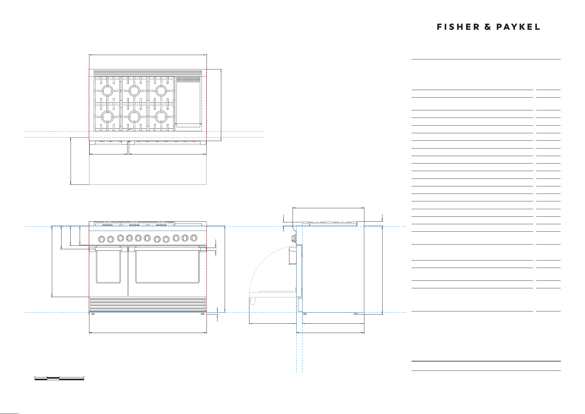
Model no:
RGV2-486GL-N, RGV2-486GL-L
RDV2-486GL-N, RDV2-486GL-L
Product Dimensions
in
A Overall height of range (from floor to cooktop,
excludinggrates and vent trim)
min 35 3/4''
max 36 3/4''
B Overall width of range
47 7/8''
C Overall depth of range (excluding handle and dials)
29 1/8''
D Depth from rear of chassis to cabinetry face - projecting
25 1/8''
E Depth from rear of chassis to cabinetry face - flush
27 11/16''
F Height from countertop to top of pan supports
1 9/16''
G Height from countertop to top of vent trim
1 3/4''
H Height from countertop to bottom of control panel
7 3/4''
I Height from countertop to top of door
8 1/16''
J Height from countertop to centre of handle
9 7/16''
K Height from countertop to bottom of door
28 7/8''
L Height from countertop to bottom of chassis
35 1/4''
M Thickness of handles (not including standoffs)
1 1/4''
N Width of left handle (including standoffs)
15 1/16''
O Width of right handle (including standoffs)
31 1/2''
P Depth of handle (measured from front of door)
3 1/16''
Q Depth of open door to cabinetry face - flush
19 1/8''
R Adjustable feet height
min 1/2''
max 1 1/2''
Cavity Dimensions
in
Overall height of cavity
min 35 3/4''
max 36 3/4''
Overall width of cavity
min 48''
Overall depth of cavity for projecting control panel
Overall depth of cavity for flush control panel
max
25 1/8''
max
27 11/16''

DATE: 24.04.2018
IMPORTANT: Throughout this guide, dimensions may vary by ±2mm (1/16'').
Read the installation guide for detailed information on installing the product.
For full installation instructions and specifications visit fisherpaykel.com
CLEARANCE DIMENSIONS
48" Professional Range
INDICATES CABINETRY CLEARANCES --------------------------------
INDICATES PRODUCT DATUM -------------------------------------------
0 5 10 20
inches
Model no:
RGV2-486GL-N, RGV2-486GL-L
RDV2-486GL-N, RDV2-486GL-L
Clearance Dimensions
in
A Minimum width of ventilation hood installed above range
- not shown*
48''
B Minimum vertical distance between countertop and cabinet
extending above counter
18''
C Minimum clearance from left and right edge of range to
nearest vertical combustible surface
12''
D Minimum clearance from cooking surface to:
– combustible surface centered above the cooking surface
– non-combustible surface centered above the cooking surface
54''
30''
E Maximum overall depth of overhead cabinetry
13''
DATUM : BOTTOM OF CHASSIS
FRONT VIEW PROFILE VIEW
DATUM :
TOP OF COUNTERTOP
CABINET FACE FOR
INSTALLATION WITH
PROJECTING CONTROL PANEL
CABINET FACE FOR
INSTALLATION WITH
FLUSH CONTROL PANEL
PLAN VIEW
MINIMUM CLEARANCE:
COMBUSTIBLE SURFACE
MAXIMUM OVERALL DEPTH
OF OVERHEAD CABINETRY
MINIMUM CLEARANCE:
ADJACENT OVERHEAD CABINET
MINIMUM CLEARANCE:
NON-COMBUSTIBLE SURFACE
MINIMUM CLEARANCE:
NEAREST VERTICAL
COMBUSTIBLE SURFACE
MINIMUM CLEARANCE:
NEAREST VERTICAL
COMBUSTIBLE SURFACE
CABINET FACE FOR INSTALLATION
WITH PROJECTING CONTROL PANEL
CABINET FACE FOR INSTALLATION
WITH FLUSH CONTROL PANEL
D
E
D
B
CC
DATE: 24.04.2018
IMPORTANT: Throughout this guide, dimensions may vary by ±2mm (1/16'').
Read the installation guide for detailed information on installing the product.
For full installation instructions and specifications visit fisherpaykel.com
CAVITY PREPARATION
48" Professional Range
0 5 10 20
inches
Model no:
RGV2-486GL-N, RGV2-486GL-L
RDV2-486GL-N, RDV2-486GL-L
Location of Electrical and Gas Supply
in
A Depth of supply area (ie maximum protrusion of gas
connection from wall)
2''
B Distance from right hand edge of range to supply area
1 1/2''
C (RGV) Height of electrical supply area (from floor)
19''
D (RGV) Height of gas supply area (from floor)
12''
E (RGV) Width of supply area
3''
F (RDV) Distance from left hand edge of range to supply area
1 1/2''
G (RDV) Height of electrical and gas supply area (from floor)
6''
Specifications
Electrical
RGV Models
Supply
120 VAC, 60Hz
Max. Current Draw
12 amp
Service
15 amp circuit
Electrical
RDV Models
Supply
120/240 VAC, 60Hz
Max. Current Draw
36 amp
Service
50 amp circuit
Gas – Natural
Connection
1/2” NPT Minimum 5/8” dia. flex line
Supply Pressure
Supply Pressure: 6” to 9” W.C.
Gas – LP
Connection
1/2” NPT Minimum 5/8” dia. flex line
Supply Pressure*
11” to 14” W.C.
A regulator is required at the LP source to provide a maximum pressure
of 14” W.C. to the range regulator.
G
RDV models
F B
FINAL POSITION OF
RANGE AGAINST WALL
ELECTRICAL & GAS
RGV models
C D
E
B
A
A
FINAL POSITION OF
RANGE AGAINST WALL
ELECTRICAL
GAS
PRODUCT & CAVITY DIMENSIONS
48" Professional Range
DATE: 24.04.2018
IMPORTANT: Throughout this guide, dimensions may vary by ±2mm (1/16'').
Read the installation guide for detailed information on installing the product.
For full installation instructions and specifications visit fisherpaykel.com
INDICATES PRODUCT DATUM -------------------------------------------
0 5 10 20
inches
47 7/8''
B
29 1/8''
35 3/4'' -
36 3/4''
29 1/8''
47 7/8''
B
DATUM : BOTTOM OF CHASSIS
A
FRONT VIEW
PROFILE VIEW
C
m
K J I H
GF
l
DATUM :
TOP OF
COUNTERTOP
CABINET FACE FOR INSTALLATION
WITH PROJECTING CONTROL PANEL
CABINET FACE FOR INSTALLATION
WITH FLUSH CONTROL PANEL
CABINET FACE FOR
INSTALLATION WITH
PROJECTING CONTROL PANEL
CABINET FACE FOR
INSTALLATION WITH
FLUSH CONTROL PANEL
p
Dq
E
C
PLAN VIEW
on
q
r
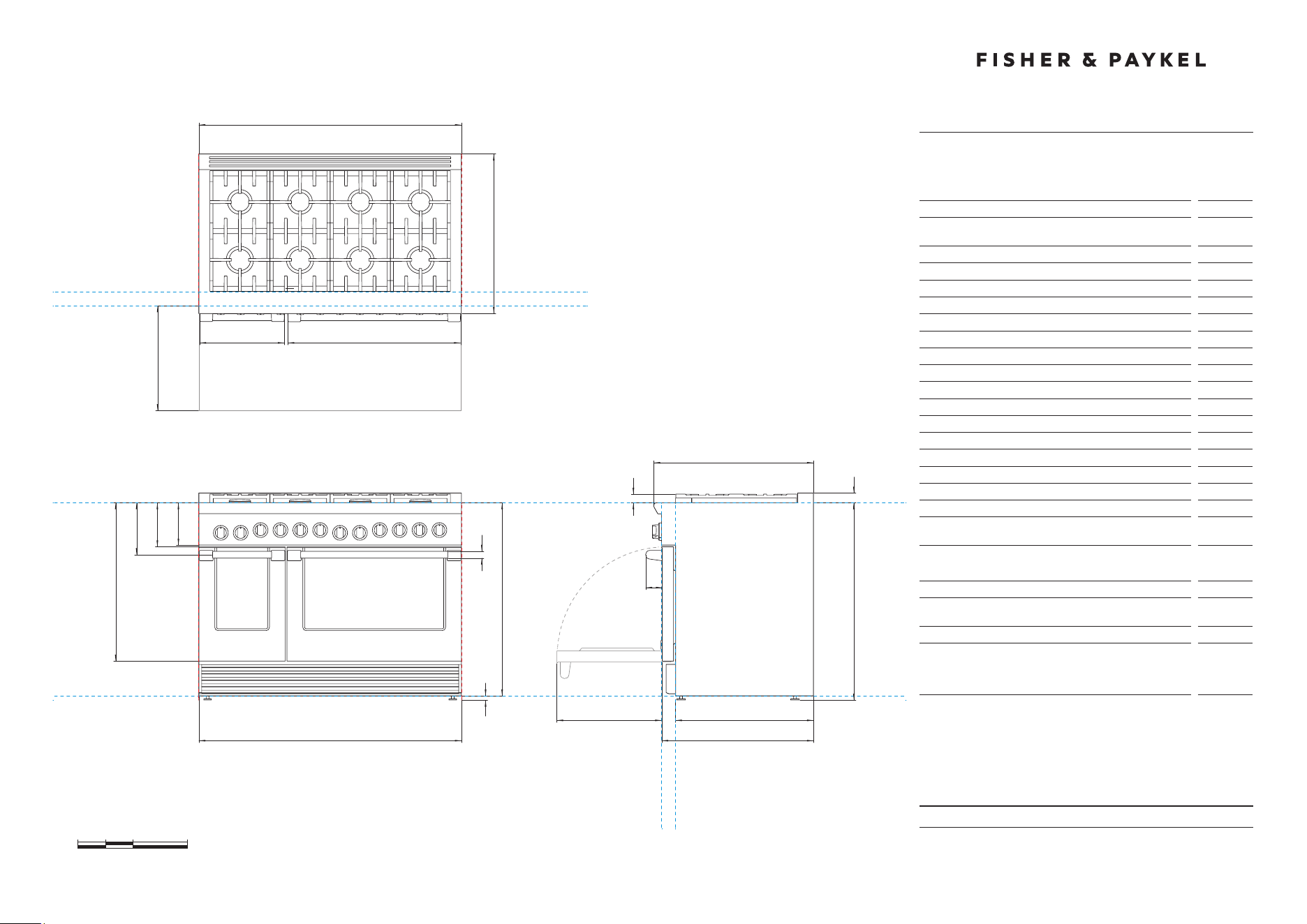
Model no:
RGV2-488-N, RGV2-488-L
RDV2-488-N, RDV2-488-L
Product Dimensions
in
A Overall height of range (from floor to cooktop,
excludinggrates and vent trim)
min 35 3/4''
max 36 3/4''
B Overall width of range
47 7/8''
C Overall depth of range (excluding handle and dials)
29 1/8''
D Depth from rear of chassis to cabinetry face - projecting
25 1/8''
E Depth from rear of chassis to cabinetry face - flush
27 11/16''
F Height from countertop to top of pan supports
1 9/16''
G Height from countertop to top of vent trim
1 3/4''
H Height from countertop to bottom of control panel
7 3/4''
I Height from countertop to top of door
8 1/16''
J Height from countertop to center of handle
9 7/16''
K Height from countertop to bottom of door
28 7/8''
L Height from countertop to bottom of chassis
35 1/4''
M Thickness of handles (not including standoffs)
1 1/4''
N Width of left handle (including standoffs)
15 1/16''
O Width of right handle (including standoffs)
31 1/2''
P Depth of handle (measured from front of door)
3 1/16''
Q Depth of open door to cabinetry face - flush
19 1/8''
R Adjustable feet height
min 1/2''
max 1 1/2''
Cavity Dimensions
in
Overall height of cavity
min 35 3/4''
max 36 3/4''
Overall width of cavity
min 48''
Overall depth of cavity for projecting control panel
Overall depth of cavity for flush control panel
max
25 1/8''
max
27 11/16''
DATE: 24.04.2018
IMPORTANT: Throughout this guide, dimensions may vary by ±2mm (1/16'').
Read the installation guide for detailed information on installing the product.
For full installation instructions and specifications visit fisherpaykel.com
CLEARANCE DIMENSIONS
48" Professional Range
INDICATES CABINETRY CLEARANCES --------------------------------
INDICATES PRODUCT DATUM -------------------------------------------
0 5 10 20
inches
Model no:
RGV2-488-N, RGV2-488-L
RDV2-488-N, RDV2-488-L
Cabinetry Dimensions
in
A Minimum width of ventilation hood installed above range
- not shown*
48''
B Minimum vertical distance between countertop and cabinet
extending above counter
18''
C Minimum clearance from left and right edge of range to
nearest vertical combustible surface
12''
D Minimum clearance from cooking surface to:
– combustible surface centered above the cooking surface
– non-combustible surface centered above the cooking surface
54''
30''
E Maximum overall depth of overhead cabinetry
13''
DATUM : BOTTOM OF CHASSIS
FRONT VIEW PROFILE VIEW
DATUM :
TOP OF COUNTERTOP
CABINET FACE FOR
INSTALLATION WITH
PROJECTING CONTROL PANEL
CABINET FACE FOR
INSTALLATION WITH
FLUSH CONTROL PANEL
PLAN VIEW
MINIMUM CLEARANCE:
COMBUSTIBLE SURFACE
MAXIMUM OVERALL DEPTH
OF OVERHEAD CABINETRY
MINIMUM CLEARANCE:
ADJACENT OVERHEAD CABINET
MINIMUM CLEARANCE:
NON-COMBUSTIBLE SURFACE
MINIMUM CLEARANCE:
NEAREST VERTICAL
COMBUSTIBLE SURFACE
MINIMUM CLEARANCE:
NEAREST VERTICAL
COMBUSTIBLE SURFACE
CABINET FACE FOR INSTALLATION
WITH PROJECTING CONTROL PANEL
CABINET FACE FOR INSTALLATION
WITH FLUSH CONTROL PANEL
D
E
D
B
CC
DATE: 24.04.2018
IMPORTANT: Throughout this guide, dimensions may vary by ±2mm (1/16'').
Read the installation guide for detailed information on installing the product.
For full installation instructions and specifications visit fisherpaykel.com
CAVITY PREPARATION
48" Professional Range
G
RGV models
RDV models
0 5 10 20
inches
Model no:
RGV2-488-N, RGV2-488-L
RDV2-488-N, RDV2-488-L
Location of Electrical and Gas Supply
in
A Depth of supply area (ie maximum protrusion of
gasconnection from wall)
2''
B Distance from right hand edge of range to supply area
1 1/2''
C (RGV) Height of electrical supply area (from floor)
19''
D (RGV) Height of gas supply area (from floor)
12''
E (RGV) Width of supply area
3''
F (RDV) Distance from left hand edge of range to supply area
1 1/2''
G (RDV) Height of electrical and gas supply area (from floor)
6''
Specifications
Electrical
RGV Models
Supply
120 VAC, 60Hz
Max. Current Draw
9 amp
Service
15 amp circuit
Electrical
RDV Models
Supply
120/240 VAC, 60Hz
Max. Current Draw
33 amp
Service
50 amp circuit
Gas – Natural
Connection
1/2” NPT Minimum 5/8” dia. flex line
Supply Pressure
Supply Pressure: 6” to 9” W.C.
Gas – LP
Connection
1/2” NPT Minimum 5/8” dia. flex line
Supply Pressure*
11” to 14” W.C.
A regulator is required at the LP source to provide a maximum pressure
of 14” W.C. to the range regulator.
C D
E
B
F B
A
A
FINAL POSITION OF
RANGE AGAINST WALL
FINAL POSITION OF
RANGE AGAINST WALL
ELECTRICAL
ELECTRICAL & GAS
GAS
DATE: 24.04.2018
IMPORTANT: Throughout this guide, dimensions may vary by ±2mm (1/16'').
Read the installation guide for detailed information on installing the product.
For full installation instructions and specifications visit fisherpaykel.com
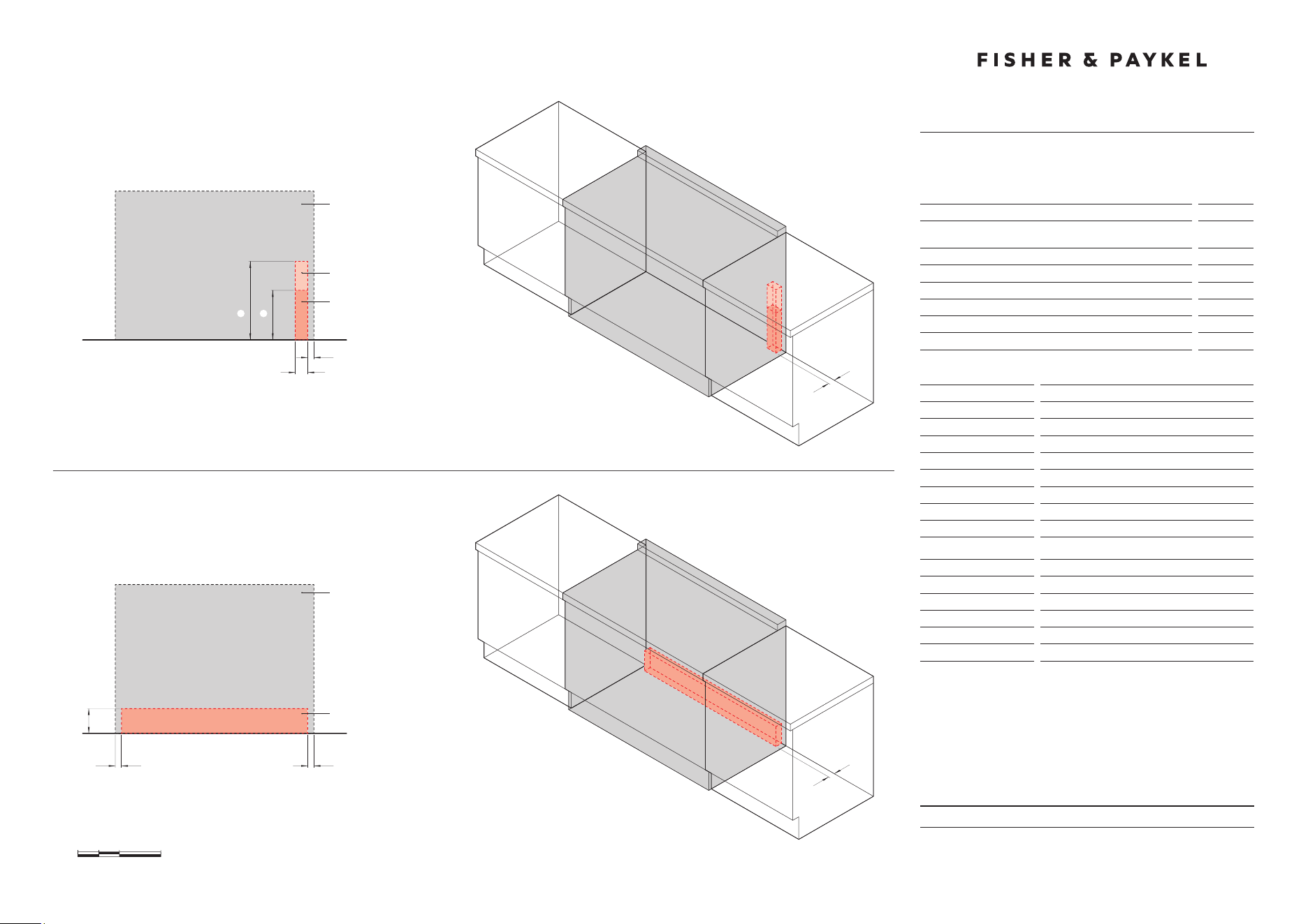
INDICATES PRODUCT DATUM -------------------------------------------
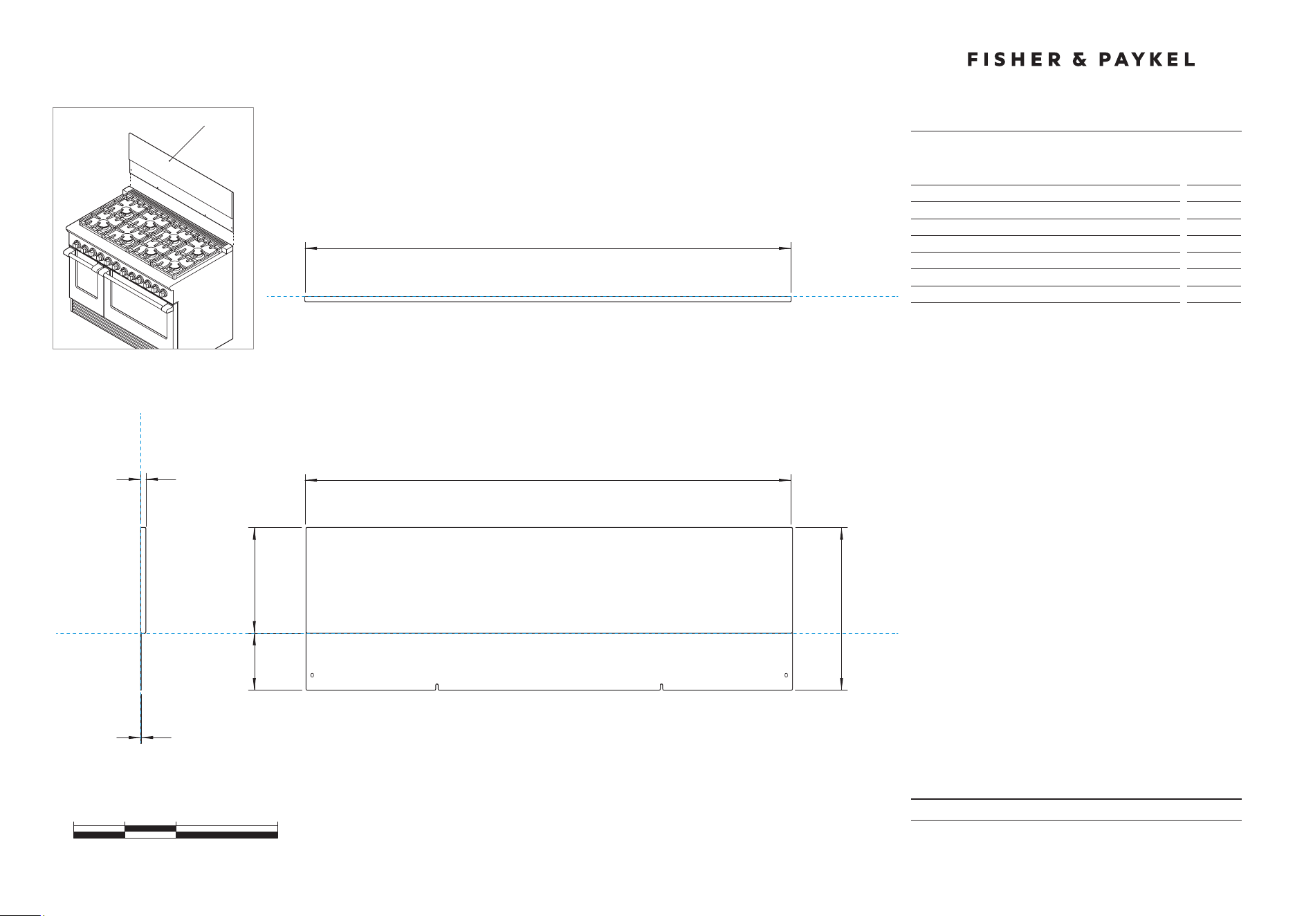
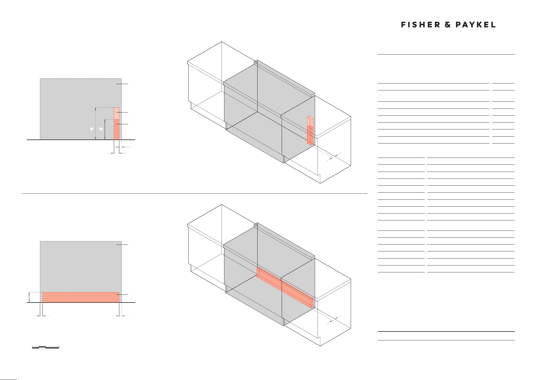
PRODUCT DIMENSIONS
48" Professional Range Backguard
DATUM : TOP OF
VENT TRIM ON RANGE
0 5 10 20
inches
47 7/8''
c
47 7/8''
c
10 3/8''
b
f
e
A
FRONT VIEW
PLAN VIEW
PROFILE VIEW
d
DATUM : BACK OF PRODUCT
DATUM : BACK OF PRODUCT
BGRV2-1248NOT TO SCALE
RGV2-488/
RDV2-488
(illustrated)
1/2''
Model no:
BGRV2-1248
Product Dimensions
in
A Height of backguard above vent trim on range
10 3/8''
B Overall height of backguard
15 15/16''
C Overall width of backguard
47 7/8''
D Overall depth of backguard
1/2
''
E Height of backguard below vent trim on range
5 9/16''
F Depth of backguard below vent trim on range
1/16
''
DATE: 24.04.2018
IMPORTANT: Throughout this guide, dimensions may vary by ±2mm (1/16'').
Read the installation guide for detailed information on installing the product.
For full installation instructions and specifications visit fisherpaykel.com
INDICATES PRODUCT DATUM -------------------------------------------
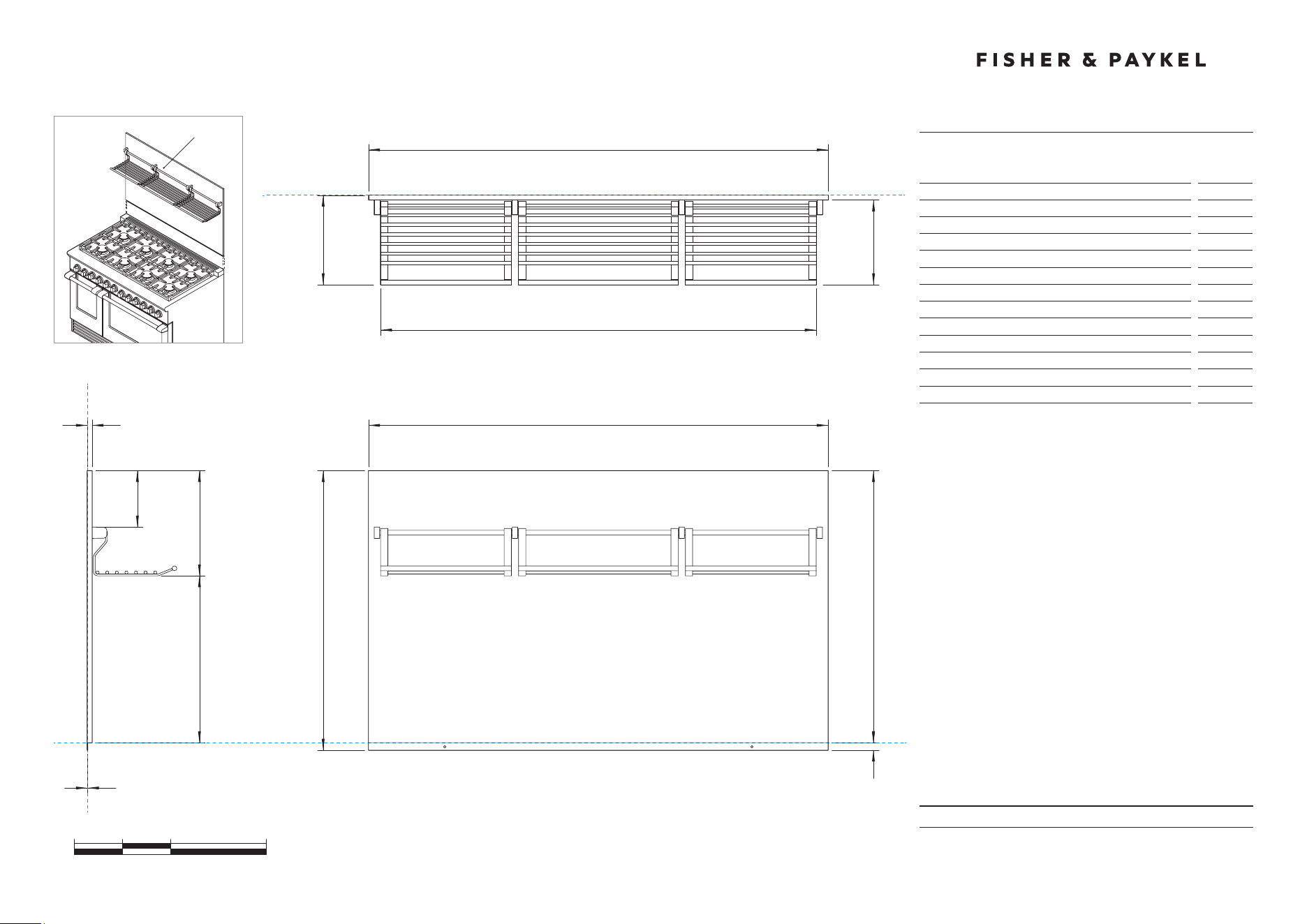
PRODUCT DIMENSIONS
48" Professional Range Backguard
0 5 10 20
inches
47 7/8"
C
47 7/8"
C
AB
G
F
I
H
l k
J
FRONT VIEW
PLAN VIEW
PROFILE VIEW
D
DATUM : BACK OF PRODUCT
DATUM : BACK OF PRODUCT
E
BGRV2-3048NOT TO SCALE
RGV2-488/
RDV2-488
(illustrated)
DATUM : TOP OF
VENT TRIM ON RANGE
28 3/8"
1/2''
Model no:
BGRV2-3048
Product Dimensions
in
A Height of backguard above vent trim on range
28 3/8"
B Overall height of backguard
29 1/8"
C Overall width of backguard
47 7/8"
D Overall depth of backguard and racks
9 5/16"
E Depth of backguard
1/2"
F Depth of racks
8 13/16"
G Width of racks
45 3/8"
H Distance from top of backguard to bottom of racks
10 15/16"
I Distance from bottom of backguard to bottom of racks
17 3/8"
J Distance from top of backguard to top of brackets
5 7/8"
K Height of backguard below vent trim on range
13/16"
L Depth of backguard below vent trim on range
1/16"
DATE: 24.04.2018
IMPORTANT: Throughout this guide, dimensions may vary by ±2mm (1/16'').
Read the installation guide for detailed information on installing the product.
For full installation instructions and specifications visit fisherpaykel.com
INDICATES PRODUCT DATUM -------------------------------------------
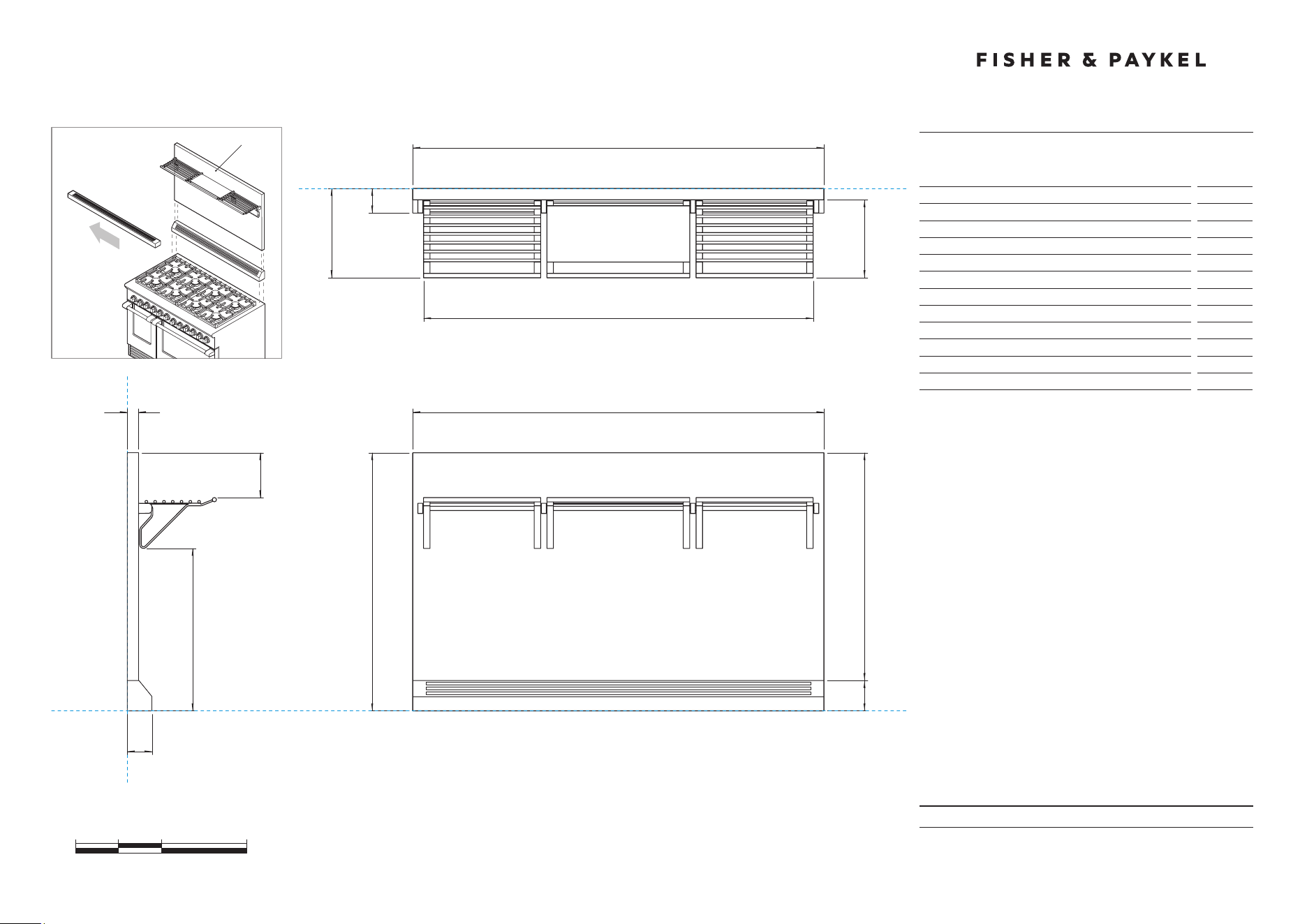
PRODUCT DIMENSIONS
48" Professional Range Backguard with Angled Vent Trim
0 5 10 20
inches
47 7/8"
B
47 7/8"
B
30"
dA
i
h
k
j
FRONT VIEW
PLAN VIEW
PROFILE VIEW
c
DATUM : BOTTOM OF ANGLED VENT TRIM
DATUM : BACK OF BACKGUARD
DATUM : BACK OF BACKGUARD
BGRV2-3048HNOT TO SCALE
g
f
f
e
Model no:
BGRV2-3048H
Product Dimensions
in
A Overall height of backguard with angled vent trim
30''
B Overall width of backguard
47 7/8''
C Overall depth of backguard and racks
10 3/8''
D Height of backguard
26 1/2''
E Height of angled vent trim
3 1/2''
F Depth of angled vent trim
2 7/8''
G Depth of backguard
1 5/16'''
H Depth of racks
9 1/16''
I Width of racks
45 3/8''
J Distance from top of backguard to top of racks
5 3/8''
K Distance from bottom of angled vent trim to bottom of racks
18 7/8''
Note: Angled vent trim supplied with BGRV2-3048H.
Remove flat vent trim and replace with angled vent trim.
RGV2-488/
RDV2-488
(illustrated)
1 5/16"

METRIC

DATE: 24.04.2018
IMPORTANT: Throughout this guide, dimensions may vary by ±2mm (1/16'').
Read the installation guide for detailed information on installing the product.
For full installation instructions and specifications visit fisherpaykel.com
INSTALL TYPE
1
WALL
ISLAND
REAR SURFACE
2
COMBUSTIBLE
NON COMBUSTIBLE
BACKGUARD OPTIONS
3
NO BACKGUARD
HIGH THICK BACKGUARD
WITH ANGLED TRIM
BGRV2-3048H
ANGLED TRIM
(Supplied with
backguard)
LOW THIN BACKGUARD
BGRV2-1248
NO BACKGUARD
HIGH THIN BACKGUARD
BGRV2-3048
CUSTOM FABRICATED* BACKGUARD
*Fabricated from non combustible materials only
CUSTOM
BACKGUARD*
Model no:
RGV2-485GD, RGV2-486GD, RGV2-486GL, RGV2-488
RDV2-485GD, RDV2-486GD, RDV2-486GL, RDV2-488
KEY DESIGN DECISIONS
48" Professional Range
MIN 152mm
CLEARANCE
MAX 12.7mm
MIN 762mm
DATE: 24.04.2018
IMPORTANT: Throughout this guide, dimensions may vary by ±2mm (1/16'').
Read the installation guide for detailed information on installing the product.
For full installation instructions and specifications visit fisherpaykel.com
INSTALL TYPE
1
WALL
ISLAND
HOOD SURROUND MATERIAL
2
NON COMBUSTIBLE
NON COMBUSTIBLE
COMBUSTIBLE
COMBUSTIBLE
VENTILATION REQUIREMENTS
48" Professional Range
584mm
MIN
762mm
MAX
914mm
MIN 762mm
MAX 914mm
762mm
762mm
914mm
914mm
584mm
Model no:
RGV2-485GD, RGV2-486GD, RGV2-486GL, RGV2-488
RDV2-485GD, RDV2-486GD, RDV2-486GL, RDV2-488
Note: RGV2-366 illustrated but all dimensions apply to the above models
Specifications
Ventilation Unit
Wall Installation
Hood
584mm Deep x Unit Width
Blower
1200 CFM
Ventilation Unit
Island Installation
Hood
762mm Deep x Unit Width
Blower
1200 CFM
Note: A suitable hood must be installed above the range. The above indicates
the minimum blower capacity recommended for hood ventilation.
PRODUCT & CAVITY DIMENSIONS
48" Professional Range
DATE: 24.04.2018
IMPORTANT: Throughout this guide, dimensions may vary by ±2mm (1/16'').
Read the installation guide for detailed information on installing the product.
For full installation instructions and specifications visit fisherpaykel.com
INDICATES PRODUCT DATUM -------------------------------------------
0 100 200 400
millimetres
DATUM : BOTTOM OF CHASSIS
1216
B
740
A
FRONT VIEW
PROFILE VIEW
C
m
K J I H
GF
l
DATUM :
TOP OF
COUNTERTOP
CABINET FACE FOR INSTALLATION
WITH PROJECTING CONTROL PANEL
CABINET FACE FOR INSTALLATION
WITH FLUSH CONTROL PANEL
CABINET FACE FOR
INSTALLATION WITH
PROJECTING CONTROL PANEL
CABINET FACE FOR
INSTALLATION WITH
FLUSH CONTROL PANEL
1216
B
908 -
933
p
Dq
E
C
740
PLAN VIEW
on
q
r
Model no:
RGV2-485GD-N, RGV2-485GD-L
RDV2-485GD-N, RDV2-485GD-L
Product Dimensions
mm
A Overall height of range (from floor to cooktop,
excludinggrates and vent trim)
min 908
max 933
B Overall width of range
1216
C Overall depth of range (excluding handle and dials)
740
D Depth from rear of chassis to cabinetry face - projecting
638
E Depth from rear of chassis to cabinetry face - flush
703
F Height from countertop to top of pan supports
40
G Height from countertop to top of vent trim
45
H Height from countertop to bottom of control panel
196
I Height from countertop to top of door
204
J Height from countertop to centre of handle
240
K Height from countertop to bottom of door
734
L Height from countertop to bottom of chassis
895
M Thickness of handles (not including standoffs)
32
N Width of left handle (including standoffs)
393
O Width of right handle (including standoffs)
801
P Depth of handle (measured from front of door)
77
Q Depth of open door to cabinetry face - flush
486
R Adjustable feet height
min 13
max 38
Cavity Dimensions
mm
Overall height of cavity
min 908
max 933
Overall width of cavity
min 1219
Overall depth of cavity for projecting control panel
Overall depth of cavity for flush control panel
max 638
max 703
DATE: 24.04.2018
IMPORTANT: Throughout this guide, dimensions may vary by ±2mm (1/16'').
Read the installation guide for detailed information on installing the product.
For full installation instructions and specifications visit fisherpaykel.com
CLEARANCE DIMENSIONS
48" Professional Range
INDICATES CABINETRY CLEARANCES --------------------------------
INDICATES PRODUCT DATUM -------------------------------------------
0 100 200 400
millimetres
DATUM : BOTTOM OF CHASSIS
FRONT VIEW PROFILE VIEW
DATUM :
TOP OF COUNTERTOP
CABINET FACE FOR
INSTALLATION WITH
PROJECTING CONTROL PANEL
CABINET FACE FOR
INSTALLATION WITH
FLUSH CONTROL PANEL
PLAN VIEW
MINIMUM CLEARANCE:
COMBUSTIBLE SURFACE
MAXIMUM OVERALL DEPTH
OF OVERHEAD CABINETRY
MINIMUM CLEARANCE:
ADJACENT OVERHEAD CABINET
MINIMUM CLEARANCE:
NON-COMBUSTIBLE SURFACE
MINIMUM CLEARANCE:
NEAREST VERTICAL
COMBUSTIBLE SURFACE
MINIMUM CLEARANCE:
NEAREST VERTICAL
COMBUSTIBLE SURFACE
CABINET FACE FOR INSTALLATION
WITH PROJECTING CONTROL PANEL
CABINET FACE FOR INSTALLATION
WITH FLUSH CONTROL PANEL
D
E
D
B
CC
Model no:
RGV2-485GD-N, RGV2-485GD-L
RDV2-485GD-N, RDV2-485GD-L
Clearance Dimensions
mm
A Minimum width of ventilation hood installed above range
- not shown*
1219
B Minimum vertical distance between countertop and cabinet
extending above counter
457
C Minimum clearance from left and right edge of range to
nearest vertical combustible surface
305
D Minimum clearance from cooking surface to:
– ombustible surface centred above the cooking surface
– non-combustible surface centred above the cooking surface
1372
762
E Maximum overall depth of overhead cabinetry
330
DATE: 24.04.2018
IMPORTANT: Throughout this guide, dimensions may vary by ±2mm (1/16'').
Read the installation guide for detailed information on installing the product.
For full installation instructions and specifications visit fisherpaykel.com
CAVITY PREPARATION
48" Professional Range
Model no:
RGV2-485GD-N, RGV2-485GD-L
RDV2-485GD-N, RDV2-485GD-L
Location of Electrical and Gas Supply
mm
A Depth of supply area (ie maximum protrusion of gas
connection from wall)
51
B Distance from right hand edge of range to supply area
38
C (RGV) Height of electrical supply area (from floor)
483
D (RGV) Height of gas supply area (from floor)
305
E (RGV) Width of supply area
76
F (RDV) Distance from left hand edge of range to supply area
38
G (RDV) Height of electrical and gas supply area (from floor)
152
Specifications
Electrical
RGV Models
Supply
120 VAC, 60Hz
Max. Current Draw
15 amp
Service
15 amp circuit
Electrical
RDV Models
Supply
120/240 VAC, 60Hz
Max. Current Draw
40 amp
Service
50 amp circuit
Gas – Natural
Connection
1/2” NPT Minimum 5/8” dia. flex line
Supply Pressure
Supply Pressure: 6” to 9” W.C.
Gas – LP
Connection
1/2” NPT Minimum 5/8” dia. flex line
Supply Pressure*
11” to 14” W.C.
A regulator is required at the LP source to provide a maximum pressure
of 14” W.C. to the range regulator
G
RDV models
F B
A
FINAL POSITION OF
RANGE AGAINST WALL
ELECTRICAL & GAS
RGV models
C D
E
B
A
FINAL POSITION OF
RANGE AGAINST WALL
ELECTRICAL
GAS
0 100 200 400
millimetres
PRODUCT & CAVITY DIMENSIONS
48" Professional Range
DATE: 24.04.2018
IMPORTANT: Throughout this guide, dimensions may vary by ±2mm (1/16'').
Read the installation guide for detailed information on installing the product.
For full installation instructions and specifications visit fisherpaykel.com
INDICATES PRODUCT DATUM -------------------------------------------
0 100 200 400
millimetres
DATUM : BOTTOM OF CHASSIS
1216
B
740
A
FRONT VIEW
PROFILE VIEW
C
m
K J I H
GF
l
DATUM :
TOP OF
COUNTERTOP
CABINET FACE FOR INSTALLATION
WITH PROJECTING CONTROL PANEL
CABINET FACE FOR INSTALLATION
WITH FLUSH CONTROL PANEL
CABINET FACE FOR
INSTALLATION WITH
PROJECTING CONTROL PANEL
CABINET FACE FOR
INSTALLATION WITH
FLUSH CONTROL PANEL
1216
B
908 -
933
p
Dq
E
C
740
PLAN VIEW
on
q
r
Model no:
RGV2-486GD-N, RGV2-486GD-L
RDV2-486GD-N, RDV2-486GD-L
Product Dimensions
mm
A Overall height of range (from floor to cooktop,
excludinggrates and vent trim)
min 908
max 933
B Overall width of range
1216
C Overall depth of range (excluding handle and dials)
740
D Depth from rear of chassis to cabinetry face - projecting
638
E Depth from rear of chassis to cabinetry face - flush
703
F Height from countertop to top of pan supports
40
G Height from countertop to top of vent trim
45
H Height from countertop to bottom of control panel
196
I Height from countertop to top of door
204
J Height from countertop to centre of handle
240
K Height from countertop to bottom of door
734
L Height from countertop to bottom of chassis
895
M Thickness of handles (not including standoffs)
32
N Width of left handle (including standoffs)
393
O Width of right handle (including standoffs)
801
P Depth of handle (measured from front of door)
77
Q Depth of open door to cabinetry face - flush
486
R Adjustable feet height
min 13
max 38
Cavity Dimensions
mm
Overall height of cavity
min 908
max 933
Overall width of cavity
min 1219
Overall depth of cavity for projecting control panel
Overall depth of cavity for flush control panel
max 638
max 703
DATE: 24.04.2018
IMPORTANT: Throughout this guide, dimensions may vary by ±2mm (1/16'').
Read the installation guide for detailed information on installing the product.
For full installation instructions and specifications visit fisherpaykel.com
INDICATES CABINETRY CLEARANCES --------------------------------
INDICATES PRODUCT DATUM -------------------------------------------
CLEARANCE DIMENSIONS
48" Professional Range
0 100 200 400
millimetres
DATUM : BOTTOM OF CHASSIS
FRONT VIEW PROFILE VIEW
DATUM :
TOP OF COUNTERTOP
CABINET FACE FOR
INSTALLATION WITH
PROJECTING CONTROL PANEL
CABINET FACE FOR
INSTALLATION WITH
FLUSH CONTROL PANEL
PLAN VIEW
MINIMUM CLEARANCE:
COMBUSTIBLE SURFACE
MAXIMUM OVERALL DEPTH
OF OVERHEAD CABINETRY
MINIMUM CLEARANCE:
ADJACENT OVERHEAD CABINET
MINIMUM CLEARANCE:
NON-COMBUSTIBLE SURFACE
MINIMUM CLEARANCE:
NEAREST VERTICAL
COMBUSTIBLE SURFACE
MINIMUM CLEARANCE:
NEAREST VERTICAL
COMBUSTIBLE SURFACE
CABINET FACE FOR INSTALLATION
WITH PROJECTING CONTROL PANEL
CABINET FACE FOR INSTALLATION
WITH FLUSH CONTROL PANEL
D
E
D
B
CC
Model no:
RGV2-486GD-N, RGV2-486GD-L
RDV2-486GD-N, RDV2-486GD-L
Clearance Dimensions
mm
A Minimum width of ventilation hood installed above range
- not shown*
1219
B Minimum vertical distance between countertop and cabinet
extending above counter
457
C Minimum clearance from left and right edge of range to
nearest vertical combustible surface
305
d Minimum clearance from cooking surface to:
– combustible surface centred above the cooking surface
– non-combustible surface centred above the cooking surface
1372
762
D Maximum overall depth of overhead cabinetry
330
DATE: 24.04.2018
IMPORTANT: Throughout this guide, dimensions may vary by ±2mm (1/16'').
Read the installation guide for detailed information on installing the product.
For full installation instructions and specifications visit fisherpaykel.com
CAVITY PREPARATION
48" Professional Range
Model no:
RGV2-486GD-N, RGV2-486GD-L
RDV2-486GD-N, RDV2-486GD-L
Location of Electrical and Gas Supply
mm
A Depth of supply area (ie maximum protrusion of
gasconnection from wall)
51
B Distance from right hand edge of range to supply area
38
C (RGV) Height of electrical supply area (from floor)
483
D (RGV) Height of gas supply area (from floor)
305
E (RGV) Width of supply area
76
F (RDV) Distance from left hand edge of range to supply area
38
G (RDV) Height of electrical and gas supply area (from floor)
152
Specifications
Electrical
RGV Models
Supply
120 VAC, 60Hz
Max. Current Draw
12 amp
Service
15 amp circuit
Electrical
RDV Models
Supply
120/240 VAC, 60Hz
Max. Current Draw
36 amp
Service
50 amp circuit
Gas – Natural
Connection
1/2” NPT Minimum 5/8” dia. flex line
Supply Pressure
Supply Pressure: 6” to 9” W.C.
Gas – LP
Connection
1/2” NPT Minimum 5/8” dia. flex line
Supply Pressure*
11” to 14” W.C.
A regulator is required at the LP source to provide a maximum pressure
of 14” W.C. to the range regulator.
G
RDV models
F B
A
FINAL POSITION OF
RANGE AGAINST WALL
ELECTRICAL & GAS
RGV models
C D
E
B
A
FINAL POSITION OF
RANGE AGAINST WALL
ELECTRICAL
GAS
0 100 200 400
millimetres
PRODUCT & CAVITY DIMENSIONS
48" Professional Range
DATE: 24.04.2018
IMPORTANT: Throughout this guide, dimensions may vary by ±2mm (1/16'').
Read the installation guide for detailed information on installing the product.
For full installation instructions and specifications visit fisherpaykel.com
INDICATES PRODUCT DATUM -------------------------------------------
0 100 200 400
millimetres
DATUM : BOTTOM OF CHASSIS
1216
B
740
A
FRONT VIEW
PROFILE VIEW
C
m
K J I H
GF
l
DATUM :
TOP OF
COUNTERTOP
CABINET FACE FOR INSTALLATION
WITH PROJECTING CONTROL PANEL
CABINET FACE FOR INSTALLATION
WITH FLUSH CONTROL PANEL
CABINET FACE FOR
INSTALLATION WITH
PROJECTING CONTROL PANEL
CABINET FACE FOR
INSTALLATION WITH
FLUSH CONTROL PANEL
1216
B
908 -
933
p
Dq
E
C
740
PLAN VIEW
on
q
r
Model no:
RGV2-486GL-N, RGV2-486GL-L
RDV2-486GL-N, RDV2-486GL-L
Product Dimensions
mm
A Overall height of range (from floor to cooktop,
excludinggrates and vent trim)
min 908
max 933
B Overall width of range
1216
C Overall depth of range (excluding handle and dials)
740
D Depth from rear of chassis to cabinetry face - projecting
638
E Depth from rear of chassis to cabinetry face - flush
703
F Height from countertop to top of pan supports
40
G Height from countertop to top of vent trim
45
H Height from countertop to bottom of control panel
196
I Height from countertop to top of door
204
J Height from countertop to centre of handle
240
K Height from countertop to bottom of door
734
L Height from countertop to bottom of chassis
895
M Thickness of handles (not including standoffs)
32
N Width of left handle (including standoffs)
393
O Width of right handle (including standoffs)
801
P Depth of handle (measured from front of door)
77
Q Depth of open door to cabinetry face - flush
486
R Adjustable feet height
min 13
max 38
Cavity Dimensions
mm
Overall height of cavity
min 908
max 933
Overall width of cavity
min 1219
Overall depth of cavity for projecting control panel
Overall depth of cavity for flush control panel
max 638
max 703
DATE: 24.04.2018
IMPORTANT: Throughout this guide, dimensions may vary by ±2mm (1/16'').
Read the installation guide for detailed information on installing the product.
For full installation instructions and specifications visit fisherpaykel.com
CLEARANCE DIMENSIONS
48" Professional Range
INDICATES CABINETRY CLEARANCES --------------------------------
INDICATES PRODUCT DATUM -------------------------------------------
0 100 200 400
millimetres
DATUM : BOTTOM OF CHASSIS
FRONT VIEW PROFILE VIEW
DATUM :
TOP OF COUNTERTOP
CABINET FACE FOR
INSTALLATION WITH
PROJECTING CONTROL PANEL
CABINET FACE FOR
INSTALLATION WITH
FLUSH CONTROL PANEL
PLAN VIEW
MINIMUM CLEARANCE:
COMBUSTIBLE SURFACE
MAXIMUM OVERALL DEPTH
OF OVERHEAD CABINETRY
MINIMUM CLEARANCE:
ADJACENT OVERHEAD CABINET
MINIMUM CLEARANCE:
NON-COMBUSTIBLE SURFACE
MINIMUM CLEARANCE:
NEAREST VERTICAL
COMBUSTIBLE SURFACE
MINIMUM CLEARANCE:
NEAREST VERTICAL
COMBUSTIBLE SURFACE
CABINET FACE FOR INSTALLATION
WITH PROJECTING CONTROL PANEL
CABINET FACE FOR INSTALLATION
WITH FLUSH CONTROL PANEL
D
E
D
B
CC
Model no:
RGV2-486GL-N, RGV2-486GL-L
RDV2-486GL-N, RDV2-486GL-L
Clearance Dimensions
mm
A Minimum width of ventilation hood installed above range
- not shown*
1219
B Minimum vertical distance between countertop and cabinet
extending above counter
457
C Minimum clearance from left and right edge of range to
nearest vertical combustible surface
305
D Minimum clearance from cooking surface to:
– combustible surface centred above the cooking surface
– non-combustible surface cent red above the cooking surface
1372
762
E Maximum overall depth of overhead cabinetry
330
DATE: 24.04.2018
IMPORTANT: Throughout this guide, dimensions may vary by ±2mm (1/16'').
Read the installation guide for detailed information on installing the product.
For full installation instructions and specifications visit fisherpaykel.com
CAVITY PREPARATION
48" Professional Range
Model no:
RGV2-486GL-N, RGV2-486GL-L
RDV2-486GL-N, RDV2-486GL-L
Location of Electrical and Gas Supply
mm
A Depth of supply area (ie maximum protrusion of
gasconnection from wall)
51
B Distance from right hand edge of range to supply area
38
C (RGV) Height of electrical supply area (from floor)
483
D (RGV) Height of gas supply area (from floor)
305
E (RGV) Width of supply area
76
F (RDV) Distance from left hand edge of range to supply area
38
G (RDV) Height of electrical and gas supply area (from floor)
152
Specifications
Electrical
RGV Models
Supply
120 VAC, 60Hz
Max. Current Draw
12 amp
Service
15 amp circuit
Electrical
RDV Models
Supply
120/240 VAC, 60Hz
Max. Current Draw
36 amp
Service
50 amp circuit
Gas – Natural
Connection
1/2” NPT Minimum 5/8” dia. flex line
Supply Pressure
Supply Pressure: 6” to 9” W.C.
Gas – LP
Connection
1/2” NPT Minimum 5/8” dia. flex line
Supply Pressure*
11” to 14” W.C.
A regulator is required at the LP source to provide a maximum pressure
of 14” W.C. to the range regulator.
G
RDV models
F B
A
FINAL POSITION OF
RANGE AGAINST WALL
ELECTRICAL & GAS
RGV models
C D
E
B
A
FINAL POSITION OF
RANGE AGAINST WALL
ELECTRICAL
GAS
0 100 200 400
millimetres
PRODUCT & CAVITY DIMENSIONS
48" Professional Range
DATE: 24.04.2018
IMPORTANT: Throughout this guide, dimensions may vary by ±2mm (1/16'').
Read the installation guide for detailed information on installing the product.
For full installation instructions and specifications visit fisherpaykel.com
INDICATES PRODUCT DATUM -------------------------------------------
0 100 200 400
millimetres
DATUM : BOTTOM OF CHASSIS
1216
B
740
A
FRONT VIEW
PROFILE VIEW
C
m
K J I H
GF
l
DATUM :
TOP OF
COUNTERTOP
CABINET FACE FOR INSTALLATION
WITH PROJECTING CONTROL PANEL
CABINET FACE FOR INSTALLATION
WITH FLUSH CONTROL PANEL
CABINET FACE FOR
INSTALLATION WITH
PROJECTING CONTROL PANEL
CABINET FACE FOR
INSTALLATION WITH
FLUSH CONTROL PANEL
1216
B
908 -
933
p
Dq
E
C
740
PLAN VIEW
on
q
r
Model no:
RGV2-488-N, RGV2-488-L
RDV2-488-N, RDV2-488-L
Product Dimensions
mm
A Overall height of range (from floor to cooktop, excluding
grates and vent trim)
min 908
max 933
B Overall width of range
1216
C Overall depth of range (excluding handle and dials)
740
D Depth from rear of chassis to cabinetry face - projecting
638
E Depth from rear of chassis to cabinetry face - flush
703
F Height from countertop to top of pan supports
40
G Height from countertop to top of vent trim
45
H Height from countertop to bottom of control panel
196
I Height from countertop to top of door
204
J Height from countertop to centre of handle
240
K Height from countertop to bottom of door
734
L Height from countertop to bottom of chassis
895
M Thickness of handles (not including standoffs)
32
N Width of left handle (including standoffs)
393
O Width of right handle (including standoffs)
801
P Depth of handle (measured from front of door)
77
Q Depth of open door to cabinetry face - flush
486
R Adjustable feet height
min 13
max 38
Cavity Dimensions
mm
Overall height of cavity
min 908
max 933
Overall width of cavity
min 1219
Overall depth of cavity for projecting control panel
Overall depth of cavity for flush control panel
max 638
max 703
DATE: 24.04.2018
IMPORTANT: Throughout this guide, dimensions may vary by ±2mm (1/16'').
Read the installation guide for detailed information on installing the product.
For full installation instructions and specifications visit fisherpaykel.com
CLEARANCE DIMENSIONS
48" Professional Range
INDICATES CABINETRY CLEARANCES --------------------------------
INDICATES PRODUCT DATUM -------------------------------------------
0 100 200 400
millimetres
DATUM : BOTTOM OF CHASSIS
FRONT VIEW PROFILE VIEW
DATUM :
TOP OF COUNTERTOP
CABINET FACE FOR
INSTALLATION WITH
PROJECTING CONTROL PANEL
CABINET FACE FOR
INSTALLATION WITH
FLUSH CONTROL PANEL
PLAN VIEW
MINIMUM CLEARANCE:
COMBUSTIBLE SURFACE
MAXIMUM OVERALL DEPTH
OF OVERHEAD CABINETRY
MINIMUM CLEARANCE:
ADJACENT OVERHEAD CABINET
MINIMUM CLEARANCE:
NON-COMBUSTIBLE SURFACE
MINIMUM CLEARANCE:
NEAREST VERTICAL
COMBUSTIBLE SURFACE
MINIMUM CLEARANCE:
NEAREST VERTICAL
COMBUSTIBLE SURFACE
CABINET FACE FOR INSTALLATION
WITH PROJECTING CONTROL PANEL
CABINET FACE FOR INSTALLATION
WITH FLUSH CONTROL PANEL
D
E
D
B
CC
Model no:
RGV2-488-N, RGV2-488-L
RDV2-488-N, RDV2-488-L
Clearance Dimensions
mm
A Minimum width of ventilation hood installed above range
- not shown*
1219
B Minimum vertical distance between countertop and cabinet
extending above counter
457
C Minimum clearance from left and right edge of range to
nearest vertical combustible surface
305
D Minimum clearance from cooking surface to:
– combustible surface centred above the cooking surface
– non-combustible surface centred above the cooking surface
1372
762
E Maximum overall depth of overhead cabinetry
330
DATE: 24.04.2018
IMPORTANT: Throughout this guide, dimensions may vary by ±2mm (1/16'').
Read the installation guide for detailed information on installing the product.
For full installation instructions and specifications visit fisherpaykel.com
CAVITY PREPARATION
48" Professional Range
Model no:
RGV2-488-N, RGV2-488-L
RDV2-488-N, RDV2-488-L
Location of Electrical and Gas Supply
mm
A Depth of supply area (ie maximum protrusion of gas
connection from wall)
51
B Distance from right hand edge of range to supply area
38
C (RGV) Height of electrical supply area (from floor)
483
D (RGV) Height of gas supply area (from floor)
305
E (RGV) Width of supply area
76
F (RDV) Distance from left hand edge of range to supply area
38
G (RDV) Height of electrical and gas supply area (from floor)
152
Specifications
Electrical
RGV Models
Supply
120 VAC, 60Hz
Max. Current Draw
9 amp
Service
15 amp circuit
Electrical
RDV Models
Supply
120/240 VAC, 60Hz
Max. Current Draw
33 amp
Service
50 amp circuit
Gas – Natural
Connection
1/2” NPT Minimum 5/8” dia. flex line
Supply Pressure
Supply Pressure: 6” to 9” W.C.
Gas – LP
Connection
1/2” NPT Minimum 5/8” dia. flex line
Supply Pressure*
11” to 14” W.C.
A regulator is required at the LP source to provide a maximum pressure
of 14” W.C. to the range regulator.
G
RDV models
F B
A
FINAL POSITION OF
RANGE AGAINST WALL
ELECTRICAL & GAS
RGV models
C D
E
B
A
FINAL POSITION OF
RANGE AGAINST WALL
ELECTRICAL
GAS
0 100 200 400
millimetres
DATE: 24.04.2018
IMPORTANT: Throughout this guide, dimensions may vary by ±2mm (1/16'').
Read the installation guide for detailed information on installing the product.
For full installation instructions and specifications visit fisherpaykel.com
INDICATES PRODUCT DATUM -------------------------------------------
PRODUCT DIMENSIONS
48" Professional Range Backguard
0 100 200 400
millimetres
1210
c
1210
c
263
13
b
f
e
A
FRONT VIEW
PLAN VIEW
PROFILE VIEW
d
DATUM : TOP OF
VENT TRIM ON RANGE
DATUM : BACK OF PRODUCT
DATUM : BACK OF PRODUCT
BGRV2-1248NOT TO SCALE
RGV2-488/
RDV2-488
(illustrated)
Model no:
BGRV2-1248
Product Dimensions
mm
A Height of backguard above vent trim on range
263
B Overall height of backguard
405
C Overall width of backguard
1210
D Overall depth of backguard
13
E Height of backguard below vent trim on range
142
F Depth of backguard below vent trim on range
1
DATE: 24.04.2018
IMPORTANT: Throughout this guide, dimensions may vary by ±2mm (1/16'').
Read the installation guide for detailed information on installing the product.
For full installation instructions and specifications visit fisherpaykel.com
PRODUCT DIMENSIONS
48" Professional Range Backguard
INDICATES PRODUCT DATUM -------------------------------------------
0 100 200 400
millimetres
1216
C
1216
C
720
AB
G
F
I
H
l k
J
FRONT VIEW
PLAN VIEW
PROFILE VIEW
D
DATUM : BACK OF PRODUCT
DATUM : BACK OF PRODUCT
E
BGRV2-3048NOT TO SCALE
RGV2-488/
RDV2-488
(illustrated)
DATUM : TOP OF
VENT TRIM ON RANGE
13
Model no:
BGRV2-3048
Product Dimensions
mm
A Height of backguard above vent trim on range
720
B Overall height of backguard
740
C Overall width of backguard
1216
D Overall depth of backguard and racks
237
E Depth of backguard
13
F Depth of racks
224
G Width of racks
1153
H Distance from top of backguard to bottom of racks
278
I Distance from bottom of backguard to bottom of racks
442
J Distance from top of backguard to top of brackets
149
K Height of backguard below vent trim on range
20
L Depth of backguard below vent trim on range
1
DATE: 24.04.2018
IMPORTANT: Throughout this guide, dimensions may vary by ±2mm (1/16'').
Read the installation guide for detailed information on installing the product.
For full installation instructions and specifications visit fisherpaykel.com
PRODUCT DIMENSIONS
48" Professional Range Backguard with Angled Vent Trim
INDICATES PRODUCT DATUM -------------------------------------------
0 100 200 400
millimetres
1216
B
1216
B
763
dA
i
h
k
j
FRONT VIEW
PLAN VIEW
PROFILE VIEW
c
DATUM : BOTTOM OF ANGLED VENT TRIM
DATUM : BACK OF BACKGUARD
DATUM : BACK OF BACKGUARD
BGRV2-3048HNOT TO SCALE
g
f
f
e
RGV2-488/
RDV2-488
(illustrated)
33
Model no:
BGRV2-3048H
Product Dimensions
mm
A Overall height of backguard with angled vent trim
763
B Overall width of backguard
1216
C Overall depth of backguard and racks
264
D Height of backguard
673
E Height of angled vent trim
90
F Depth of angled vent trim
72
G Depth of backguard
33
H Depth of racks
230
I Width of racks
1152
J Distance from top of backguard to top of racks
136
K Distance from bottom of angled vent trim to bottom of racks
480
Note: Angled vent trim supplied with BGRV2-3048H.
Remove flat vent trim and replace with angled vent trim.

IMPORTANT: The product dimensions and specifications
applyat the date of issue. Under our policy of continuous
product improvement, these dimensions and specifications
may change at any time. Dimensions may vary by ±2mm (1/16").
Please read the installation guide for detailed information
oninstalling the product or visit fisherpaykel.com.
April 2018