
Visit our website at: http://www.harborfreight.com
email our technical support at: [email protected]
24278E-B
14" STATIONARY WOODCUTTING
BANDSAW
70813
Visit our website at: http://www.harborfreight.com
70813
Owner’s Manual & Safety Instructions
Save This Manual Keep this manual for the safety warnings and precautions, assembly,
operating, inspection, maintenance and cleaning procedures. Write the product’s serial number in the
back of the manual (or month and year of purchase if product has no number). Keep this manual and the
receipt in a safe and dry place for future reference. 24e
When unpacking, make sure that the product is intact
and undamaged. If any parts are missing or broken,
please call 1-888-866-5797 as soon as possible.
Copyright
©
2024 by Harbor Freight Tools
®
. All rights reserved.
No portion of this manual or any artwork contained herein may be reproduced in
any shape or form without the express written consent of Harbor Freight Tools.
Diagrams within this manual may not be drawn proportionally. Due to continuing
improvements, actual product may differ slightly from the product described herein.
Tools required for assembly and service may not be included.
read this material before using this product.
Failure to do so can result in serious injury.
SaVe tHiS ManuaL.

Page 2 For technical questions, please call 1-888-866-5797. 70813
SaFety OperatiOn MaintenanceSetup
table of contents
Safety ................................................ 2
Specifications .................................... 6
Setup ................................................ 6
Operation ......................................... 11
Maintenance .................................... 13
Parts List and Diagram .................... 16
Warranty .......................................... 20
WarninG SyMBOLS anD DeFinitiOnS
This is the safety alert symbol. It is used to alert you to potential personal injury hazards.
Obey all safety messages that follow this symbol to avoid possible injury or death.
Indicates a hazardous situation which, if not avoided,
will result in death or serious injury.
Indicates a hazardous situation which, if not avoided,
could result in death or serious injury.
Indicates a hazardous situation which, if not avoided,
could result in minor or moderate injury.
Addresses practices not related to personal injury.
iMpOrtant SaFety inFOrMatiOn
General tool Safety Warnings
read all safety warnings and instructions.
Failure to follow the warnings and instructions may result in electric shock, fire and/or serious injury.
Save all warnings and instructions for future reference.
1. KEEP GUARDS IN PLACE and in working order.
2. REMOVE ADJUSTING KEYS AND
WRENCHES. Form habit of checking to
see that keys and adjusting wrenches are
removed from tool before turning it on.
3. KEEP WORK AREA CLEAN.
Cluttered areas and benches invite accidents.
4. DON’T USE IN DANGEROUS ENVIRONMENT.
Don’t use power tools in damp or wet locations,
or expose them to rain. Keep work area well lighted.
5. KEEP CHILDREN AWAY. All visitors should
be kept safe distance from work area.
6. MAKE WORKSHOP KID PROOF with padlocks,
master switches, or by removing starter keys.
7. DON’T FORCE TOOL. It will do the job better
and safer at the rate for which it was designed.
8. USE RIGHT TOOL. Don’t force tool or attachment
to do a job for which it was not designed.

Page 3For technical questions, please call 1-888-866-5797.70813
SaFetyOperatiOnMaintenance Setup
table a: recOMMenDeD MiniMuM Wire GauGe
FOr eXtenSiOn cOrDS
(120 VOLt)
naMepLate
aMpereS
(at full load)
eXtenSiOn cOrD
LenGtH
25′ 50′ 100′ 150′
0 – 6 18 16 16 14
6.1 – 10 18 16 14 12
10.1 – 12 16 16 14 12
12.1 – 16 14 12 Do not use.
9. USE PROPER EXTENSION CORD. Make sure your
extension cord is in good condition. When using
an extension cord, be sure to use one heavy
enough to carry the current your product will
draw. An undersized cord will cause a drop in line
voltage resulting in loss of power and overheating.
Table A shows the correct size to use depending
on cord length and nameplate ampere rating.
If in doubt, use the next heavier gauge.
The smaller the gauge number, the heavier the cord.
10. WEAR PROPER APPAREL. Do not wear
loose clothing, gloves, neckties, rings, bracelets,
or other jewelry which may get caught in moving
parts. Nonslip footwear is recommended.
Wear protective hair covering to contain long hair.
11. ALWAYS USE SAFETY GLASSES. Also use
face or dust mask if cutting operation is dusty.
Everyday eyeglasses only have impact resistant
lenses, they are NOT safety glasses.
12. SECURE WORK. Use clamps or a vise to hold
work when practical. It’s safer than using your
hand and it frees both hands to operate tool.
13. DON’T OVERREACH. Keep proper
footing and balance at all times.
14. MAINTAIN TOOLS WITH CARE. Keep
tools sharp and clean for best and safest
performance. Follow instructions for
lubricating and changing accessories.
15. DISCONNECT TOOLS before servicing;
when changing accessories, such as
blades, bits, cutters, and the like.
16. REDUCE THE RISK OF UNINTENTIONAL
STARTING. Make sure switch is in
off position before plugging in.
17. USE RECOMMENDED ACCESSORIES.
Consult the owner’s manual for recommended
accessories. The use of improper accessories
may cause risk of injury to persons.
18. NEVER STAND ON TOOL. Serious injury
could occur if the tool is tipped or if the
cutting tool is unintentionally contacted.
19. CHECK DAMAGED PARTS. Before further use
of the tool, a guard or other part that is damaged
should be carefully checked to determine that
it will operate properly and perform its intended
function – check for alignment of moving parts,
binding of moving parts, breakage of parts,
mounting, and any other conditions that may
affect its operation. A guard or other part that is
damaged should be properly repaired or replaced.
20. DIRECTION OF FEED. Feed work into
a blade or cutter against the direction of
rotation of the blade or cutter only.
21. NEVER LEAVE TOOL RUNNING UNATTENDED.
TURN POWER OFF. Don’t leave tool
until it comes to a complete stop.
General tool Safety Warnings (cont.)
Page 4 For technical questions, please call 1-888-866-5797. 70813
SaFety OperatiOn MaintenanceSetup
Grounding instructions
tO preVent eLectric SHOcK anD DeatH FrOM incOrrect GrOunDinG Wire
cOnnectiOn
reaD anD FOLLOW tHeSe inStructiOnS:
110-120 Vac Grounded tools: tools with three prong plugs
1. In the event of a malfunction or breakdown,
grounding provides a path of least resistance for
electric current to reduce the risk of electric shock.
This tool is equipped with an electric cord having an
equipment-grounding conductor and a grounding
plug. The plug must be plugged into a matching
outlet that is properly installed and grounded in
accordance with all local codes and ordinances.
2. Do not modify the plug provided – if it will
not fit the outlet, have the proper outlet
installed by a qualified electrician.
3. Improper connection of the equipment-grounding
conductor can result in a risk of electric shock.
The conductor with insulation having an outer
surface that is green with or without yellow
stripes is the equipment-grounding conductor.
If repair or replacement of the electric cord or
plug is necessary, do not connect the equipment-
grounding conductor to a live terminal.
4. Check with a qualified electrician or service
personnel if the grounding instructions are
not completely understood, or if in doubt as
to whether the tool is properly grounded.
5. Use only 3-wire extension cords that
have 3-prong grounding plugs and 3-pole
receptacles that accept the tool’s plug.
6. Repair or replace damaged or
worn cord immediately.
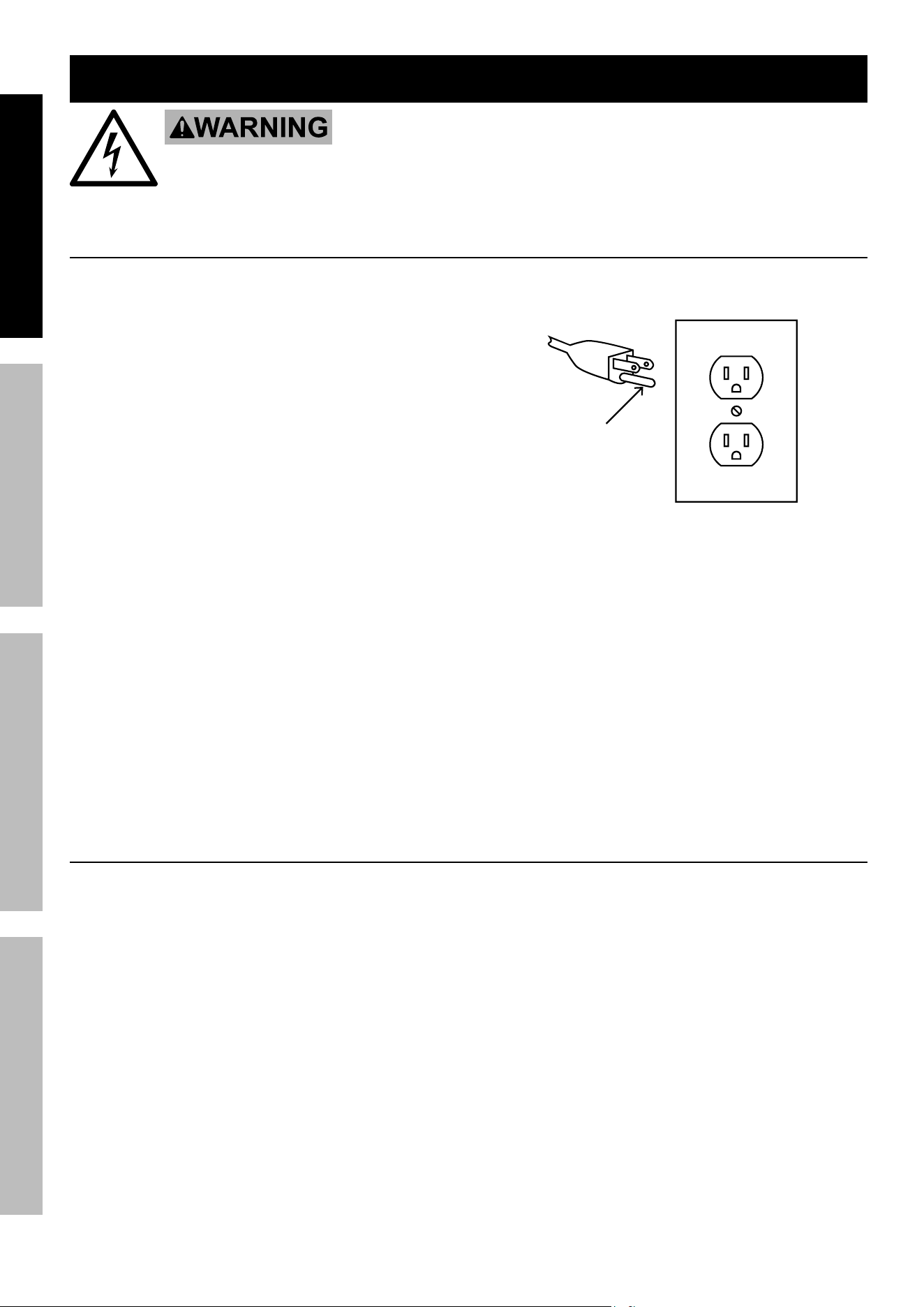
125 Vac 3-prong plug and Outlet
(for up to 125 Vac and up to 15 a)
Grounding
pin
7. This tool is intended for use on a circuit that has
an outlet that looks like the one illustrated above in
125 Vac 3-prong plug and Outlet. The tool has a
grounding plug
that looks like the plug illustrated above in
125 Vac 3-prong plug and Outlet.
8. The outlet must be properly installed and grounded
in accordance with all codes and ordinances.
9. Do not use an adapter to connect
this tool to a different outlet.
Band Saw Safety Warnings
For your Own Safety read instruction
Manual Before Operating Saw
1. Wear eye protection.
2. Do not remove jammed cutoff pieces
until blade has stopped.
3. Maintain proper adjustment of blade tension,
blade guides, and thcorrosion bearings.
4. Adjust upper guide to just clear workpiece.
5. Hold workpiece firmly against table.
6. Use special care when unpacking or
replacing bandsaw blade. Blade can be
under tension and may suddenly uncoil.
Wear ANSI-approved safety glasses under a
full face shield and heavy-duty work gloves.
7. DO nOt Operate WitH any GuarD
DiSaBLeD, DaMaGeD, Or reMOVeD.
8. Remove Switch Key after use and before
removing a jammed workpiece.
9. Secure properly to a hard, level surface before use.
10. Hot motor! to prevent injury, do not touch
motor during, or immediately after, use.
11. The use of accessories or attachments not
recommended by the manufacturer may
result in a risk of injury to persons.
12. When servicing use only identical replacement parts.

Page 5For technical questions, please call 1-888-866-5797.70813
SaFetyOperatiOnMaintenance Setup
13. Only use safety equipment that has been approved
by an appropriate standards agency. Unapproved
safety equipment may not provide adequate
protection. Eye protection must be ANSI-approved
and breathing protection must be NIOSH-approved
for the specific hazards in the work area.
14. Stay alert, watch what you are doing and use
common sense when operating a power tool.
Do not use a power tool while you are tired or
under the influence of drugs, alcohol or medication.
A moment of inattention while operating power
tools may result in serious personal injury.
15. Industrial applications must follow OSHA guidelines.
16. Maintain labels and nameplates on the tool.
These carry important safety information.
If unreadable or missing, contact
Harbor Freight Tools for a replacement.
17. Avoid unintentional starting.
Prepare to begin work before turning on the tool.
18. People with pacemakers should consult their
physician(s) before use. Electromagnetic fields in
close proximity to heart pacemaker could cause
pacemaker interference or pacemaker failure.
19. The warnings, precautions, and instructions
discussed in this instruction manual cannot
cover all possible conditions and situations
that may occur. It must be understood by the
operator that common sense and caution are
factors which cannot be built into this product,
but must be supplied by the operator.
Vibration Safety
This tool vibrates during use. Repeated or
long-term exposure to vibration may cause
temporary or permanent physical injury,
particularly to the hands, arms and shoulders. To
reduce the risk of vibration-related injury:
1. Anyone using vibrating tools regularly or for an
extended period should first be examined by a
doctor and then have regular medical check-ups
to ensure medical problems are not being caused
or worsened from use. Pregnant women or
people who have impaired blood circulation to
the hand, past hand injuries, nervous system
disorders, diabetes, or Raynaud’s Disease should
not use this tool. If you feel any medical or
physical symptoms related to vibration (such as
tingling, numbness, and white or blue fingers),
seek medical advice as soon as possible.
2. Do not smoke during use. Nicotine reduces
the blood supply to the hands and fingers,
increasing the risk of vibration-related injury.
3. Use tools with the lowest vibration when there
is a choice between different processes.
4. Include vibration-free periods each day of work.
5. Grip tool as lightly as possible (while still keeping
safe control of it). Let the tool do the work.
6. To reduce vibration, maintain the tool as
explained in this manual. If any abnormal
vibration occurs, stop use immediately.
SaVe tHeSe inStructiOnS.
Band Saw Safety Warnings (cont.)

Page 6 For technical questions, please call 1-888-866-5797. 70813
SaFety OperatiOn MaintenanceSetup
Specifications
Electrical Rating 120VAC / 60Hz / 10A
Motor No Load Speed 1750 RPM
Blade Speed 3600 SFPM (High)
1800 SFPM (Low)
Throat Depth 13-3/8″
Cutting Height 8″
Table Pivot (Tilt) Capacity 3° (left) 45° (right)
Blade Size 1/8″ to 3/4″ W x 100″ L
Dust Port 4″ diameter
Weight 180 lbs.
Setup - Before use:
read the entire iMpOrtant SaFety inFOrMatiOn section at the beginning of this
manual including all text under subheadings therein before set up or use of this product.
tO preVent SeriOuS inJury FrOM acciDentaL OperatiOn:
turn the power Switch of the tool off and unplug the tool from its electrical
outlet before performing any procedure in this section.
note: For additional information regarding the parts listed in the following pages,
refer to the Assembly Diagram near the end of this manual.
WarninG! Bandsaw is heavy; use an assistant to help lift it from carton and assemble.
Page 7For technical questions, please call 1-888-866-5797.70813
SaFetyOperatiOnMaintenance Setup
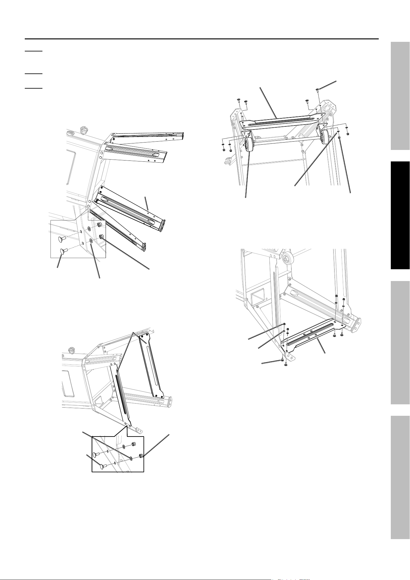
Stand assembly
note: Stand Legs (178) with rubber foot
located on side of the switch on column.
note: Stand Legs mount on inside of Saw Base.
note: Do not fully tighten fasteners until
Stand assembly is complete.
1. Attach Stand Legs (178) to Saw Base, using
Bolts (176), Washers (10) and Nuts (63).
Stand Leg (178)
Bolt (176)
Washer (10)
nut (63)
2. Attach two Long Braces (177) to inside of Stand
Legs, using Bolts (176), Washers (10) and Nuts (63).
Long Brace (177)
Bolt (176)
Washer (10)
nut (63)
3. Attach Short Brace (B) (194) and Roller Wheel
Assembly (187) onto right Stand Legs using
Bolts (195), Washers (10), and Nuts (63).
Bolt (195)
Short Brace (B) (194)
roller Wheel
assembly (187)
Washer (10)
nut (63)
4. Attach Short Brace (A) (194) onto left Stand
Legs,using Bolts (179), Washers (10) and Nuts (63).
Short Brace
(a) (194)
Bolt (179)
Washer (10)
nut (63)
Page 8 For technical questions, please call 1-888-866-5797. 70813
SaFety OperatiOn MaintenanceSetup
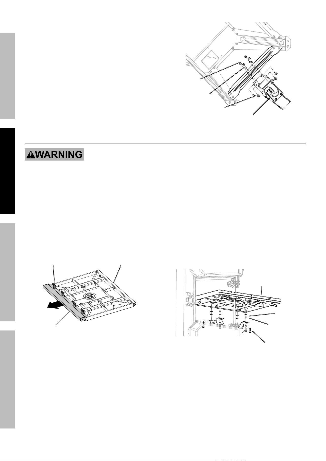
5. Attach Foot Pedal Brake Assembly (192)
onto Short Brace (A), using Bolts (3),
Washers (10) and Nuts (63).
6. Place Band Saw upright.
7. Tighten all Fasteners on Band
Saw stand and assembly.
8. Raise Brake Foot Pedal to stabilize the saw
before proceeding with further assembly.
Bolt (3)
Foot pedal Brake assembly (192)
nut (63)
Washer (10)
Work table assembly
tO preVent SeriOuS inJury FrOM acciDentaL OperatiOn:
turn the power Switch of the tool off and unplug the tool from its electrical
outlet before performing any procedure in this section.
tO preVent SeriOuS inJury:
DO nOt Operate WitH any GuarD DiSaBLeD, DaMaGeD, Or reMOVeD.
tO preVent inJury:
Wear heavy-duty work gloves and anSi-approved safety goggles whenever
handling blade. DO nOt Wear GLOVeS WHiLe SaWinG.
1. Loosen four Lock Handle (116)
under Work Table (68).
2. Remove Guide Rail (71).
Lock Handle (116)
Guide rail (71)
Work table (68)
3. Place Work Table onto Band Saw while
carefully guiding blade through slot.
4. Place Screw (110) Through Band Saw.
5. Place Spring Washer (111) and
Washer (112) onto Screw.
6. Insert Screw end into Work Table.
7. Tighten Screw.
Screw (110)
Washer
(112)
Spring
Washer (111)
Work table (68)
8. Replace Guide Rail onto Work Table
and Tighten Lock Handle.
Page 9For technical questions, please call 1-888-866-5797.70813
SaFetyOperatiOnMaintenance Setup
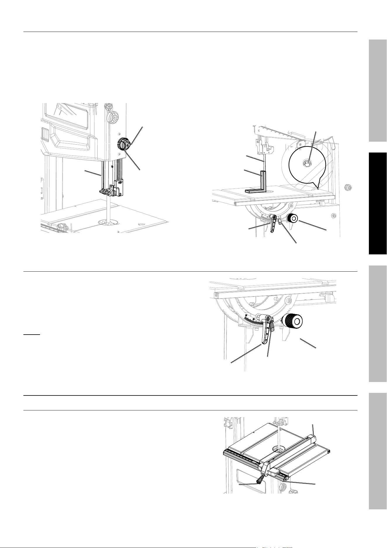
Squaring Work table to Saw Blade
1. Turn Blade Guide Lock Knob
(inner) counterclockwise.
2. Turn Blade Guide Adjustment Knob
(outer) clockwise, while lifting Blade
Guide as far as it will go.
3. Turn Blade Guide Lock Handle clockwise.
Lock
Knob
Blade
Guide
adjustment
Knob
4. Place a square (not included) on the Work Table
and flush against blade. Do not deflect blade.
5. Loosen Work Table Lock Handle and rotate Angle
Adjustment Handle to align 90° to square.
6. Tighten Work Table Lock Handle.
7. Turn Adjusting Bolt until Bolt touches Saw Housing.
8. Make sure Blade is square to Work Table.
9. Loosen Scale Indicator and align
with zero. Retighten Indicator.
adjusting Bolt
Square (not
included)
Blade
adjustment
Handle
Scale indicator
Lock Handle
Work table tilt adjustment
1. Turn Work Table Lock Handle counterclockwise.
2. Rotate Angle Adjustment Handle until Scale
Indicator reaches desired angle with Angle Scale.
3. Turn Work Table Lock Handle clockwise to tighten.
note: Lock Handle is adjustable. Pull out on handle
and rotate to new position, then release handle.
Lock
Handle
Scale
indicator
adjustment
Handle
additional assembly
rip Fence
1. Place Rip Fence onto Work Table and Guide Rail so
that Rip Fence Lock Lever is at front of Guide Rail.
2. Push down on Rip Fence Lock Lever.
Lock Lever Guide rail
rip Fence
Page 10 For technical questions, please call 1-888-866-5797. 70813
SaFety OperatiOn MaintenanceSetup
exhaust port install
1. Connect a dust collection system to Dust Port
and secure with hose clamp (not included).
Miter Gauge
1. Insert Miter Gauge into desired
guide grooves of Work Table.
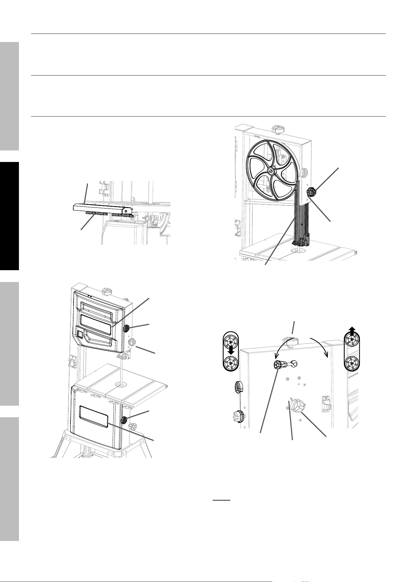
Saw Blade removal
1. Disconnect Band Saw from power source.
2. Loosen four Lock Handles under Work Table.
3. Remove Guide Rail.
Lock
Handles
Guide
rail
4. Rotate upper and lower Door Lock Knobs clockwise.
5. Open upper and lower Wheel Covers.
upper
Wheel cover
Lower
Wheel
cover
upper
Door
Lock
Knob
Blade
Guide
Lock
Handle
Lower
Door Lock
Knob
6. Rotate Blade Guide Lock Handle counterclockwise.
7. Rotate Blade Guide Adjustment Handle
counterclockwise to position Blade
Guide Assembly to lowest position.
8. Rotate Blade Guide Lock Handle
clockwise to tighten.
Blade Guide
adjustment
Handle
Blade Guide
Lock Handle
Blade Guide
assembly
9. Rotate Blade Tension Release Lever
counterclockwise to release blade tension.
To release To tighten
Blade tension
release Lever
Blade tracking
Lock Handle
Blade tracking
adjustment
Handle
Blade tensioning Handle
Figure a
10. Carefully remove Saw Blade.
note: Saw teeth must be oriented downward
and facing toward Guide Rail.
11. Reverse procedure to install new saw blade.

Page 11For technical questions, please call 1-888-866-5797.70813
SaFetyOperatiOnMaintenance Setup
Saw Blade tracking and tensioning
1. Disconnect Band Saw from power source.
2. Open upper and lower Wheel Cover.
3. Make sure that Blade Tension Release
Lever is in tighten position.
4. Rotate Blade Tracking Lock Handle
counterclockwise, see Figure A.
cautiOn! Do not touch Blade with hands.
5. Manually rotate upper Wheel and turn Blade
Tracking Adjustment Handle until Blade is
centered over upper and lower Wheels.
6. Rotate Blade Tracking Lock Handle
clockwise to tighten, see Figure A.
7. Rotate Blade Tensioning Handle until desired
blade tension reached, see Figure A. View tension
scale through window in Upper Wheel Cover.
8. Close upper and lower Wheel Covers.
Operating instructions
read the entire iMpOrtant SaFety inFOrMatiOn section at the beginning of this
manual including all text under subheadings therein before set up or use of this product.
tool Set up
tO preVent SeriOuS inJury FrOM acciDentaL OperatiOn:
turn the power Switch of the tool off and unplug the tool from its electrical
outlet before performing any procedure in this section.
tO preVent SeriOuS inJury:
DO nOt Operate WitH any GuarD DiSaBLeD, DaMaGeD, Or reMOVeD.
tO preVent inJury:
Wear heavy-duty work gloves and anSi-approved safety goggles whenever
handling blade. DO nOt Wear GLOVeS WHiLe SaWinG.
Workpiece and Work area Set up
1. Designate a work area that is clean and well-lit.
The work area must not allow access by children
or pets to prevent distraction and injury.
2. Route the power cord along a safe route to reach
the work area without creating a tripping hazard or
exposing the power cord to possible damage. The
power cord must reach the work area with enough
extra length to allow free movement while working.
3. Secure loose workpieces using a vise or
clamps (not included) to prevent movement
while working. A workpiece that hangs
over the edge of the Work Table 5 inches or
more needs to be supported properly.
4. There must not be objects, such as utility lines,
nearby that will present a hazard while working.
upper and Lower Blade Guide adjustment
note: The height of the Blade Guard should be
adjusted prior to every operation to accommodate the
height of the work piece. The Blade Guard should be no
more than 1/8″ from the upper edge of the workpiece.
upper Blade Guide
1. Loosen two Lock Handles.
2. Adjust Guide Bearings so that they are equal
or less than 0.030″ away from Blade.
3. Tighten two Lock Handles.
4. Loosen the Socket Head Bolt.
5. Adjust Thrust Bearing so it is equal or less
than 0.040″ away from back of blade.
6. Tighten Socket Head Bolt.
7. Loosen Blade Guard Lock Handle.

Page 12 For technical questions, please call 1-888-866-5797. 70813
SaFety OperatiOn MaintenanceSetup
8. Rotate Blade Guard Adjustment
Handle to adjust height of blade guide
assembly to 1/8″ from workpiece.
9. Tighten Blade Guard Lock Knob.
Lower Blade Guide
1. Loosen two Lock Handles to adjust Guide Bearings.
2. Adjust Guide Bearings so that they are equal
or less than 0.030 away from the blade.
3. Tighten two Lock Knobs.
4. Loosen Socket Head Bolt and adjust the
Thrust Bearing so that it is equal or less
than 0.040″ away from back of blade.
5. Tighten Socket Head Bolt.
≤0.75mm ≤0.75mm
≤1mm
Lock Handle
Guide Bearings
Socket
Head Bolt
Blade Guard
Lock Handle
Blade Guard
adjustment
Handle
thrust
Bearing

Page 13For technical questions, please call 1-888-866-5797.70813
SaFetyOperatiOnMaintenance Setup
General Operating instructions
tO preVent SeriOuS inJury FrOM entanGLeMent:
Keep hands clear of Blade at all times and do not wear gloves when sawing.
note: the blade is not tensioned during
shipment to prevent damage. it must be properly
tensioned and tracked before use. See Saw
Blade tracking and tensioning on page 11.
1. types of cut
a. Standard cuts are at 90° angle to the Work Table
Use a push stick to guide the workpiece
through the Saw Blade.
b. contour cuts are accomplished by guiding
the workpiece free-handed for curve shapes.
When using this guiding method, use both hands
to follow the desired path and keep the workpiece
flat against the Work Table. Stand in front of the
Work Table and use both hands over the part
of the Work Table to the right of the Blade.
c. Bevel cuts are when the Work Table is tilted
and proper work guide methods are used.
Tilt the Work Table, refer to Work Table Tilt
Adjustment on page 9, to correct angle.
2. This Band Saw is designed for cutting hard
and soft woods and most plastics. It is
equipped with a Miter Gauge Scale used to
secure the workpiece at a desired angle to
produce angle cuts. Use the built-in Scale to
adjust the Miter Gauge to the required angle.
3. Turn on Band Saw and allow it to reach to
full speed before beginning to saw.
4. Use push-sticks, or blocks (when required) to
move workpiece through the Blade. Use a smooth,
steady action to feed work through the blade.
5. Make sure the workpiece feeds against
the toothed side of the Blade.
6. To prevent accidents, turn off the tool and
disconnect its power supply after use. Clean, then
store the tool indoors out of children’s reach.
Maintenance and Servicing
procedures not specifically explained in this manual must
be performed only by a qualified technician.
tO preVent SeriOuS inJury FrOM acciDentaL OperatiOn:
turn the power Switch of the tool off and unplug the tool from its electrical
outlet before performing any procedure in this section.
tO preVent SeriOuS inJury FrOM tOOL FaiLure:
Do not use damaged equipment. if abnormal noise or vibration
occurs, have the problem corrected before further use.
cleaning, Maintenance, and Lubrication
1. BeFOre eacH uSe, inspect the general
condition of the tool. Check for:
• blade straightness and teeth sharpness,
• vibration-free operation,
• loose hardware,
• misalignment or binding of moving parts,
• cracked or broken parts,
• damaged electrical wiring, and
• any other condition that may
affect its safe operation.
2. Do not allow saw dust to accumulate
on or in Band Saw.
3. Keep the Wheels clean. Debris on Wheels will
cause poor tracking and possible Blade slippage.
4. Keep mechanisms and sliding surfaces
clean and free of debris.

Page 14 For technical questions, please call 1-888-866-5797. 70813
SaFety OperatiOn MaintenanceSetup
5. Shielded Ball Bearings do not need
lubrication. Small amounts of lightweight
machine oil can be applied to belt tension
mechanisms and sliding surfaces.
6. Paste wax can be applied occasionally to Work
Table to keep it slick and corrosion free.
7. aFter uSe, disconnect from power source, clean
by brushing and wiping with clean, moist cloth.
8. If storing for a long period, release tension on the
Blade using the Blade Tensioning Release Lever.
Refer to, Saw Blade Tracking and Tensioning
on page 11. The blade’s tension and tracking
will need to be adjusted after thus storing.
9. WarninG! if the supply cord of this power
tool is damaged, it must be replaced only
by a qualified service technician.
10. Clear all saw dust from Dust Tube at base
of Band Saw. Do not let dust accumulate.
Occasionally, vacuum out entire Band Saw.
record product’s Serial number Here:
note: If product has no serial number, record month and year of purchase instead.
note: Some parts are listed and shown for illustration purposes only, and are not available
individually as replacement parts. Specify UPC 193175514677 when ordering parts.

Page 15For technical questions, please call 1-888-866-5797.70813
SaFetyOperatiOnMaintenance Setup
pLeaSe reaD tHe FOLLOWinG careFuLLy
THE MANUFACTURER AND/OR DISTRIBUTOR HAS PROVIDED THE PARTS LIST AND ASSEMBLY DIAGRAM
IN THIS MANUAL AS A REFERENCE TOOL ONLY. NEITHER THE MANUFACTURER OR DISTRIBUTOR
MAKES ANY REPRESENTATION OR WARRANTY OF ANY KIND TO THE BUYER THAT HE OR SHE IS
QUALIFIED TO MAKE ANY REPAIRS TO THE PRODUCT, OR THAT HE OR SHE IS QUALIFIED TO REPLACE
ANY PARTS OF THE PRODUCT. IN FACT, THE MANUFACTURER AND/OR DISTRIBUTOR EXPRESSLY
STATES THAT ALL REPAIRS AND PARTS REPLACEMENTS SHOULD BE UNDERTAKEN BY CERTIFIED AND
LICENSED TECHNICIANS, AND NOT BY THE BUYER. THE BUYER ASSUMES ALL RISK AND LIABILITY
ARISING OUT OF HIS OR HER REPAIRS TO THE ORIGINAL PRODUCT OR REPLACEMENT PARTS
THERETO, OR ARISING OUT OF HIS OR HER INSTALLATION OF REPLACEMENT PARTS THERETO.
troubleshooting
problem possible causes Likely Solutions
Tool will
not start.
1. Cord not connected.
2. No power at outlet.
3. Tool’s thermal reset breaker tripped
(if equipped).
4. Internal damage or wear.
(Carbon brushes or switch, for example.)
1. Check that cord is plugged in.
2. Check power at outlet. If outlet is unpowered,
turn off tool and check circuit breaker.
If breaker is tripped, make sure circuit is right
capacity for tool and circuit has no other loads.
3. Turn off tool and allow to cool. Press reset button on tool.
4. Have technician service tool.
Tool operates
slowly.
Extension cord too long or
wire size too small.
Eliminate use of extension cord. If an extension cord
is needed, use one with the proper diameter for its
length and load. See table a on page 3.
Performance
decreases
over time.
1. Accessory dull or damaged.
2. Carbon brushes worn or damaged.
1. Keep cutting accessories sharp. Replace as needed.
2. Have qualified technician replace brushes.
Excessive noise
or rattling.
Internal damage or wear. (Carbon
brushes or bearings, for example.)
Have technician service tool.
Overheating. 1. Forcing machine to work too fast.
2. Blade too coarse or too
fine for workpiece.
3. Accessory dull or damaged.
4. Blocked motor housing vents.
5. Motor being strained by long or
small diameter extension cord.
1. Allow machine to work at its own rate.
2. Use Blade with correct pitch.
3. Keep cutting accessories sharp. Replace as needed.
4. Wear ANSI-approved safety goggles and
NIOSH-approved dust mask/respirator while
blowing dust out of motor using compressed air.
5. Eliminate use of extension cord. If an extension cord
is needed, use one with the proper diameter for its
length and load. See table a on page 3.
Cuts are not
straight
1. Work not square with Table.
2. Dull Blade.
3. Blade Guide Assembly loose.
1. Use Miter Gauge; adjust tilt of head at 90°.
2. Replace Blade.
3. Tighten Blade Guide.
Blade dulling
too rapidly
1. Blade is too coarse.
2. Hard spots on material.
3. Blade installed backwards.
1. Use a finer tooth Blade.
2. Increase pressure more gently on object being cut.
3. Remove Blade and turn inside out before reinstalling.
Frequent Saw
Blade Breakage
1. Blade is too coarse for
workpiece being cut.
2. Guides/Guards are misaligned.
3. Possible Blade Weld Cracking.
1. Use a Saw Blade with a finer pitch.
2. Adjust the Guides/Guards. Replace the Saw Blade.
Workpiece cuts
appear rough
1. Workpiece being fed into
Saw Blade to fast.
2. Blade is too coarse for
material being cut.
1. Slow down the speed at which you are
feeding material through the blade.
2. Use a blade with a finer pitch.
Follow all safety precautions whenever diagnosing or servicing the tool.
Disconnect power supply before service.

Page 16 For technical questions, please call 1-888-866-5797. 70813
SaFety OperatiOn MaintenanceSetup
part Description Qty
1 Flat Key (type C) 1
2 Motor Pulley 1
3 Bolt 13
4 Motor Components 1
5 Bolt 4
6 Dust Outlet 1
7 Driving Axle 1
8 Nut 4
9 Spring Washer 14
10 Flat Washer 58
11 Screw (A) 1
12 Cross Recessed Pan
Head Tapping Screw
2
13 Guide Rod 1
14 Angular Adjusting
Shim
1
15 Set Screw 3
16 Pointer Spring 1
17 Steel Ball 1
18 Angler Pointer 1
19 Friction Pad 3
20 Goniometer 1
21 Arm pointer 1
22 Cross recessed
pan head screw
1
23 Brush screw 1
24 Brush 1
25 Set (A) 1
26 Large Flat Pad 4
27 Hex Lock Nut 7
28 Large Flat Pad 3
29 Angler Mounting Base 1
30 Bolt 1
31 Pusher Bar 1
32 Fine Adjustment
Locking Handle
1
33 Adjusting Pinch 1
34 Angler Locking
Handle
1
35 Handle Cover 2
36 Bolt 1
37 Power Cord
38 Tensioning Lever
Handle Seat
1
39 Tensioning Eccentric 1
40 Tensioning Handle 1
41 Tensioning
Handle Cover
1
42 Column Plug 1
43 Bearing Adjustment
Handle
4
44 Set (B) 5
45 Bearing 5
46 Flat Washer 9
47 Cylindrical Pin (B) 3
48 Screw (C) 1
part Description Qty
49 Cylindrical Pin (A) 1
50 Fixed Seat (B) 1
51 Fixed Seat (A) 1
52 Set Screw 3
53 Locking Block 1
54 Lifting Body 1
55 Rack 1
56 Handle Spring 1
57 Locking Handle 1
58 Angle Adjusting Gear 1
59 Angle Locking
Handle Nut
1
60 Buffer Cap 1
61 Set Screw 1
62 Tension Ring 1
63 Hex Lock Nut 43
64 Rear Guide Rail
Plug (left)
2
65 Cross Countersunk
Head Tapping Screw
4
66 Rear Ruler Seat 1
67 Bolt 1
68 Work Table 1
69 Strip Guard 1
70 Ruler Seat Plug (left) 1
71 Guide Rail 1
72 Scale Plate 1
73 Ruler Seat Plug (right) 1
74 Needle Bearing 1
75 Bearing Shaft 1
76 Clip 1
77 Positioning Block 1
78 Cylindrical Pin 1
79 Bolt 2
80 Bolt 5
81 Cross Pan
Head Screw
1
82 Scale Pointer 1
83 Guide Pipe
Fixing Seat
1
84 Cylindrical Pin 1
85 Cylindrical Pin 1
86 Steel Ball 1
87 Pointer Spring 1
88 Screw 1
89 Clamping
Handle Cover
1
90 Clamping Handle (B) 1
91 Nut 1
92 Eccentric Wheel 1
93 Locking Plate 1
94 Cross Pan
Head Screw
4
95 Flat Washer 10
96 Spring Plate 1
97 Spring Washer 4
part Description Qty
98 Nut 4
99 Locking Plate
Spring Plate
1
100 Cross Pan
Head Screw
2
101 Guide Seat
Friction Pad
1
102 Guide Tube Screw 1
103 Guide Tube 1
104 Screw (C) 1
105 Guide Tube Roller 1
106 Rear Clamping Seat 1
107 Rear Locking Plate 1
108 Guide System Spring 1
109 Cylindrical Pin 1
110 Screw 4
111 Spring Washer 4
112 Flat Washer 4
113 Shaft Ring 1
114 Angle Locking Screw 1
115 Angle Set Screw 2
116 Lock Handle 4
117 Fixed Base 1
118 Angle Adjusting Plate 2
119 Eccentric Stopper 1
120 Bolt 4
121 Angle Adjusting
Seat Assembly
1
122 Bolt 2
123 Handle 1
124 N/A
125 Tensioning Screw 1
126 Tension Spring 1
127 Tensioning Block 1
128 Bolt 3
129 Support Rod 3
130 Tension Indicator Rod 1
131 Pointer Screw 2
132 Tensioning Pointer 1
133 Pointer Nut 1
134 Clip 2
135 Upper Pulley
Fixing Seat
2
136 Tension Rod 1
137 Tensioning Block (B) 1
138 Rotating Shaft 1
139 Upper Pulley Shaft 1
140 Bearing 4
141 Retaining Ring 4
142 Shaft Ring 3
143 Saw Blade 1
144 Pulley 2
145 Locking Pinch 1
146 Locking Hand Spring 1
147 Pulley Pad 1
148 Lifting Handle 1
parts List and Diagram
parts List

Page 17For technical questions, please call 1-888-866-5797.70813
SaFetyOperatiOnMaintenance Setup
part Description Qty
149 Adjusting Screw 1
150 Gear (B) 1
151 Body Assembly 1
152 Switch Panel 1
153 Switch 1
154 Stop Block 1
155 Wave Washer 1
156 Safety Baffle Screw
(with glue)
1
157 Passive Multi
Wedge Pulley
1
158 Tensioning
Wheel Axle
1
159 Screw 1
160 Stop Ring 1
161 Dust Collecting Box 1
162 Screw Rod 1
163 Elastic Cylindrical Pin 1
164 Pulley Tightening
Handle
1
165 Belt Pulley
Tension Cover
1
166 Shaft Ring 1
167 Bearing 2
168 Retaining Ring
For Hole
2
169 Tension Pulley 1
170 Bolt 3
171 Lower Panel
Assembly
1
172 Upper Panel
Assembly
1
part Description Qty
173 Door Lock Screw 2
174 Door Lock Knob 2
175 Window Bezel 1
176 Cup Head Square
Neck Screw
28
177 Long Braces 2
178 Stand Legs 4
179 Cup Head Square
Neck Screw
4
180 Hex Lock Nut 4
181 Foot 2
182 Cross Recessed
Pan Head Screw
4
183 Foot Pedal (B) 1
184 Shaft Ring 2
185 Roller 2
186 Roller Support (A) 1
187 Roller Shaft 1
188 Pedal Rotation Pin 1
189 Roller Support (B) 1
190 Bolt 1
191 Foot Pedal (C) 1
192 Foot Pedal Brake
Assembly
1
193 Foot Pedal (A) 1
194 Short Brace (B) 1
195 Cup Head Square
Neck Screw
4
196 N/A
197 Lifting Body Plug 1
198 Angle Adjusting
Handle
1
part Description Qty
199 Locking Handle Screw 1
200 Slider (B) 2
201 Nut 1
202 V-Ribbed Belt 1
203 Saw Blade Guard 1
204 Tightener 2
205 H.S.Bolt 1
206 Large Flat Pad 1
207 H.S.Bolt 1
208 H.S.Bolt 2
209 Hex Headed Bolt 4
210 H.S. Pan Head Bolt 4
211 H.S.Bolt 4
212 H.S.Bolt 2
213 Sponge Pad B 2
214 Large Flat Pad 1
215 Spring Washer 3
216 6mm Washer 2
217 Bush 1
218 Rear Rail End
Cover, Right
1
219 Lower Protection
Cover
1
220 C ring 1
221 Tapered Cotter 8x26 1
222 Tension Label 1
223 Allen Key 1
224 Allen Key 1
225 Allen Key 1
226 Allen Key 1
227 Earth Connection
Terminal
2
228 Washer 2
parts List (continued)
Page 18 For technical questions, please call 1-888-866-5797. 70813
SaFety OperatiOn MaintenanceSetup
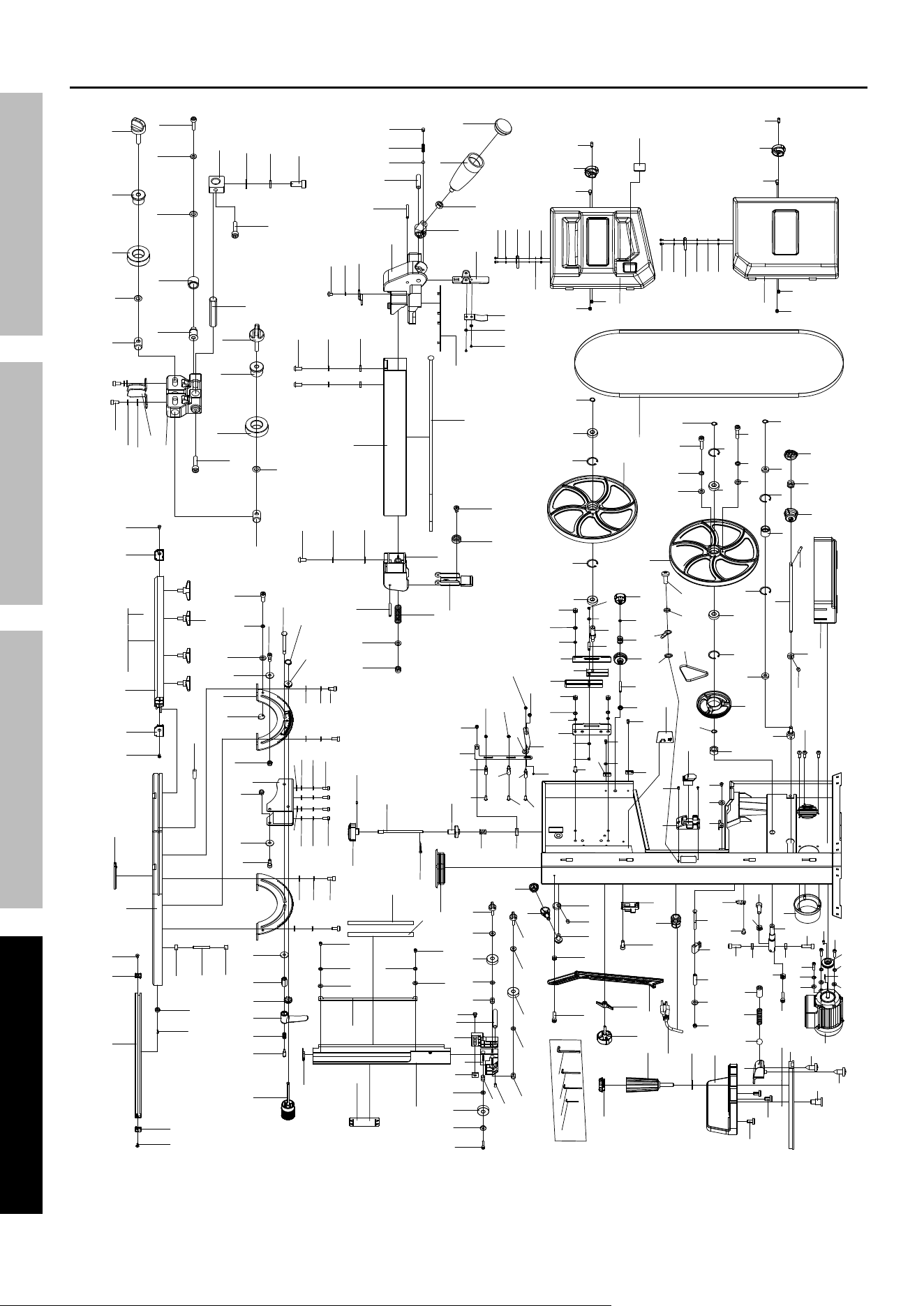
assembly Diagram
(52)
1
2
211
4
8
9
10
6
7
11
12
13
14
15
16
17
18
19
20
21
22
23
24
25
27
28
34
26
29
30
31
32
33
35
36
(8)
38
39
40
41
(52)
42
43
44
45
46
47
(207)
48
49
50
51
53
(46)
(45)
(44)
52
54
55
197
198
199
56
57 58
59
214
60
61
62
209
63
64
65
66
218
(65)
68
69
(65)
70
71
72
73
(65)
(43)
(44)
(45)
(47)
75
74
76
77
67
(9)
(10)
79
78
(43)
(44)
(45)
(47)
205
80
(9)
(10)
81
82
83
84
85
86
87
88
89
90
91
92
98
97
96
95
94
93
99
(95)
100
101
102
(95)
103
104
105
106
107
108
109
(10)
(63)
110
111
(58)
113
114
115
117
(26)
118
119
116
(27)
120
121
(9)
(10)
(3)
(26)
(115)
(110)
(111)
(112)
122
123
125
126
127
128
129
130
131
(63)
132
133
134
135
136
137
(135)
138
139
141
140
144
(141)
(140)
142
145
146
147
148
149
150
(80)
200
151
143
152
(94)
153
154
155 156
201
(12)
158
159
161
160
162
163
165
(27)
164
168
167
169
(168)
(167)
157
(141)
(144)
166
(9)
170
(10)
(142)
(63)
171
(98)
(97)
(96)
(95)
(94)
(95)
(63)
172
173
174
208
175
(173)
(174)
(208)
202
37
203
206
207
(26)
210
5
3
212
(95 )
(97 )
213
(28)
(46)
215
216
(131)
217
(91)
(111)
(112)
(95)
(46)
(46)
219
(46)
(215)
220
221
222
227
228
(97)
(94)
204
(63)
(63)
(211)
(12)
(19)
(5)
(122)
(95 )
(3)
(9)
(10)
(216)
(27)
112
(80)
(9)
(10)
(80)
(112)
(111)
(91)
(26)
(134)
(9)
(170)
(10)
(141)
(140)
(140)
(10)
(9)
(8)
(8)
(5)
(5)
(8)
(46)
(45)
(44)
(43)
(47)
(47)
(213)
(200)
(63)
(63)
(128)
(128)
(129)
(129)
(97 )
(142)
(10)
223
224
225
226
Page 19For technical questions, please call 1-888-866-5797.70813
SaFetyOperatiOnMaintenance Setup
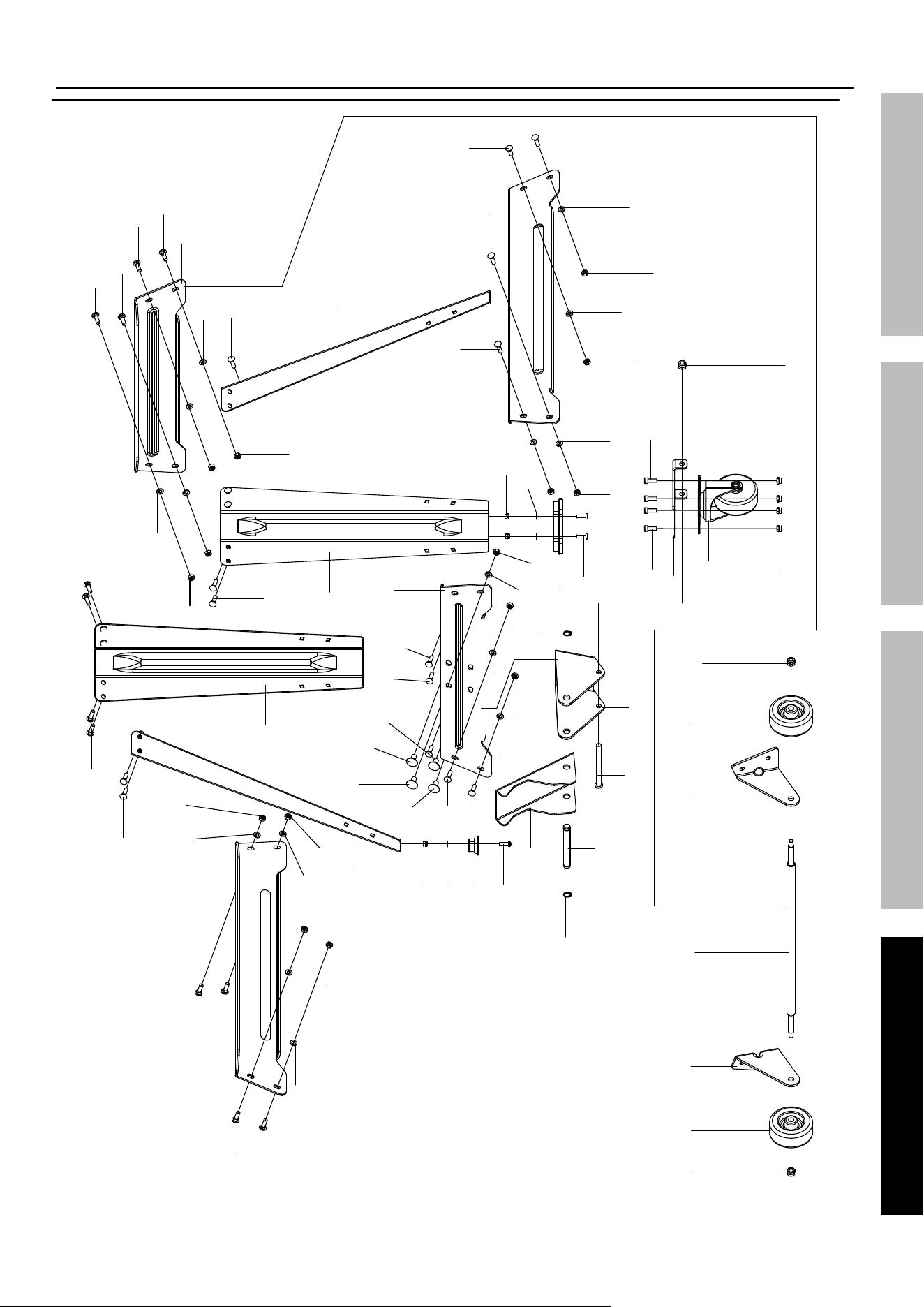
assembly Diagram (continued)
176
177
(10)
(63)
178
180
(46)
181
182
183
188
184
179
(178 )
(27)
185
186
187
189
190
(186)
(27)
191
(63)
(3)
192
193
(27)
(184)
(63)
(112)
(10)
194
(178 )
(63)
(10)
(195)
(194)
(178)
(176 )
(177)
(63)
(10)
(27)
(176)
(10)
(63)
(176)
(176)
(176)
(195)
(176)
(10)
(63)
(176)
(176)
(179)
(176)
(176)
(10)
(63)
(176)
(176)
(3)
(182)
(181)
(46)
(180)
(63)
(10)
(63)
(10)
195
(195)
(10)
(63)
(179)
(179)
(176)

Limited 90 Day Warranty
Harbor Freight Tools Co. makes every effort to assure that its products meet high quality and durability standards,
and warrants to the original purchaser that this product is free from defects in materials and workmanship for the
period of 90 days from the date of purchase. This warranty does not apply to damage due directly or indirectly,
to misuse, abuse, negligence or accidents, repairs or alterations outside our facilities, criminal activity, improper
installation, normal wear and tear, or to lack of maintenance. We shall in no event be liable for death, injuries
to persons or property, or for incidental, contingent, special or consequential damages arising from the use of
our product. Some states do not allow the exclusion or limitation of incidental or consequential damages, so the
above limitation of exclusion may not apply to you. THIS WARRANTY IS EXPRESSLY IN LIEU OF ALL OTHER
WARRANTIES, EXPRESS OR IMPLIED, INCLUDING THE WARRANTIES OF MERCHANTABILITY AND FITNESS.
To take advantage of this warranty, the product or part must be returned to us with transportation charges
prepaid. Proof of purchase date and an explanation of the complaint must accompany the merchandise.
If our inspection verifies the defect, we will either repair or replace the product at our election or we may
elect to refund the purchase price if we cannot readily and quickly provide you with a replacement. We will
return repaired products at our expense, but if we determine there is no defect, or that the defect resulted
from causes not within the scope of our warranty, then you must bear the cost of returning the product.
This warranty gives you specific legal rights and you may also have other rights which vary from state to state.
26677 agoura road, calabasas, ca 91302 • 1-888-866-5797