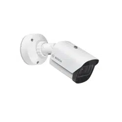
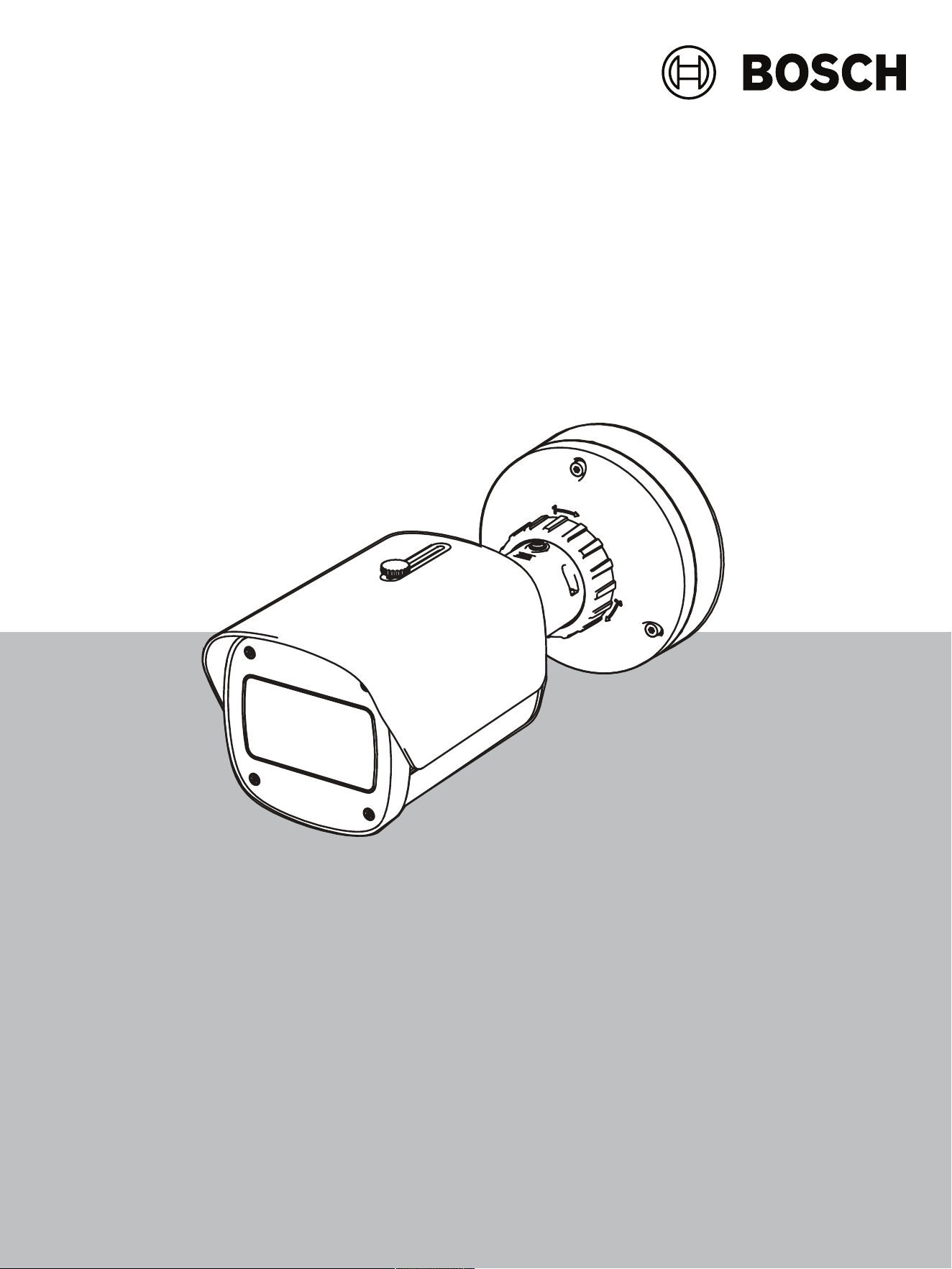


DINION 7100i IR Table of contents | en 3
Bosch Security Systems B.V.
User manual
2023-06 | V02 | F.01U.390.686
Table of contents
1
Browser connection 5
1.1 System requirements 5
1.2 Establishing the connection 5
1.3 Password protection in camera 5
2
System overview 7
2.1 Live 7
2.2 Playback 7
2.3 Configuration 7
2.4 Dashboard 8
3
Operation via the browser 9
3.1 Live page 9
3.2 Playback page 10
3.2.1 Selecting the recording stream 11
3.2.2 Searching for recorded video 11
3.2.3 Exporting recorded video 11
3.2.4 Track list 11
3.2.5 Controlling playback 11
3.3 Dashboard 12
4
Configuration 13
4.1 General 13
4.1.1 Identification 13
4.1.2 User Management 13
4.1.3 Date/Time 14
4.2 Web Interface 15
4.2.1 Appearance 15
4.2.2 'Live' functions 17
4.3 Connectivity 18
4.3.1 Cloud services 18
4.3.2 Accounts 18
4.3.3 DynDNS 19
4.4 Camera 19
4.4.1 Installer Menu 19
4.4.2 Display Stamping 21
4.4.3 Positioning 24
4.4.4 Scene Mode 27
4.4.5 Color 28
4.4.6 ALC (Automatic Level Control) 28
4.4.7 Illuminator 30
4.4.8 Enhance 30
4.4.9 Scene Mode Scheduler 31
4.4.10 Encoder Streams 31
4.4.11 Encoder Statistics 34
4.4.12 Privacy Masks 34
4.4.13 Audio 35
4.4.14 Pixel Counter 35
4.5 Recording 36
4.5.1 Storage Management 36
4.5.2 Recording Profiles 38

4 en | Table of contents DINION 7100i IR
2023-06 | V02 | F.01U.390.686
User manual
Bosch Security Systems B.V.
4.5.3 Maximum Retention Time 39
4.5.4 Recording Scheduler 40
4.5.5 Recording Status 40
4.5.6 Recording Statistics 41
4.5.7 Image Posting 41
4.5.8 SD Card Status 41
4.6 Alarm 42
4.6.1 Alarm Connections 42
4.6.2 Video Content Analysis (VCA) 43
4.6.3 Audio Alarm 43
4.6.4 Alarm Email 44
4.6.5 Alarm Inputs 45
4.6.6 Alarm Outputs 45
4.6.7 Auxiliary Power 45
4.6.8 Alarm Task Editor 46
4.7 Network 46
4.7.1 Network Services 46
4.7.2 Network Access 46
4.7.3 Advanced 48
4.7.4 Network Management 49
4.7.5 Multicast 50
4.7.6 IPv4 Filter 52
4.8 Service 52
4.8.1 Maintenance 52
4.8.2 Licenses 53
4.8.3 Certificates 53
4.8.4 Logging 54
4.8.5 System Overview 54
5
Troubleshooting 55
5.1 Physical reset button 55
6
Appendices 57
6.1 Copyright notices 57
6.2 More information 57

DINION 7100i IR Browser connection | en 5
Bosch Security Systems B.V.
User manual
2023-06 | V02 | F.01U.390.686
1 Browser connection
A computer with a web browser (Google Chrome, Microsoft Edge, or Mozilla Firefox) is used
to receive live images, control the unit, and replay stored sequences. The unit is configured
over the network using the browser.
1.1 System requirements
Our recommendations are:
– Computer with Dual core HyperThreading processor or better
– Graphic card with performance that matches or is better than the resolution of the
camera
– Windows10 or later
– Network access
– Google Chrome, Microsoft Edge, or Mozilla Firefox
- or -
Application software, for example, VideoSecurityClient, BoschVideoClient or BVMS.
Note:
To see live images in your browser it might be necessary to download and install the MPEG-
ActiveX from the Bosch download store.
1.2 Establishing the connection
The unit must have a valid IP address and a compatible subnet mask to operate on your
network. By default, DHCP is pre-set at the factory to On and so your DHCP server assigns an
IP address. With no DHCP server the default address is automatically assigned via link-local
address.
The Project Assistant app or Configuration Manager (version 7.50 or higher) can be used to
find the IP address. Download the software from https://downloadstore.boschsecurity.com
:
1. Start the web browser.
2. Enter the IP address of the device as the URL.
3. During the initial installation, confirm any security questions that show.
If a RADIUS server is used for network access control (802.1x authentication), you must
configure the device before the device can communicate with the network.
To configure the device, connect it directly to a computer using a network cable and then set
the service-level password.
Note:
If you cannot connect, the unit may have reached its maximum number of connections.
Depending on the device and network configuration, each unit can have up to 50 web browser
connections, or up to 100 connections via BoschVideoClient or BVMS.
1.3 Password protection in camera
The device is password-protected. The first time that any user accesses the device, the device
will prompt the user to set a password at the service level.
The camera requires a strong password. Follow the prompts in the dialog box, which specifies
what is required. The system measures the strength of the password that you enter.
Make sure the password obeys these conditions:
– 8 to 19 characters in length
– Upper and lower case letters
– Minimum of 1 digit
6 en | Browser connection DINION 7100i IR
2023-06 | V02 | F.01U.390.686
User manual
Bosch Security Systems B.V.
– Minimum of 1 special character
These special characters are not allowed: '@', '&', '<', '>', ':', '+'
When you use Configuration Manager to access your device for the first time, you must set the
initial password of the device in Configuration Manager. The Users section (General > Unit
Access > Users) displays the message, "Before you can use this device you have to secure it
with an initial password."
Note: After you set the initial password, a "lock" icon appears next to the device name in the
Devices list in Configuration Manager.
You can also launch the device webpage directly. In the device webpage, an initial password
page appears, displaying input fields and a password strength gauge.
Enter the user name (“service”) and a password in the appropriate fields. Refer to the section
User Management for more information.
After a service-level password is set for the device, the device displays a dialog box that
prompts users to enter the user name (“service”) and the service-level password every time
that they access the device.
1. Fill in the fields User name and Password.
2. Click OK. If the password is correct, the desired page appears.
Note: New releases of software may require you to set a new and stronger password.
Notices for local certification - Korea
i
Notice!
Use the internal USB-C port only for administration purposes.
i
Notice!
This is an industrial product and has only been tested for industrial use. Do not use this
product for residential or home monitoring purposes.
i
Notice!
This product does not include an amplifier. For audio output, use a built-in amplifier speaker.
DINION 7100i IR System overview | en 7
Bosch Security Systems B.V.
User manual
2023-06 | V02 | F.01U.390.686
2 System overview
Note: None of the pages are accessible until after you set a service-level password.
When a connection is established, the Live page is initially displayed.
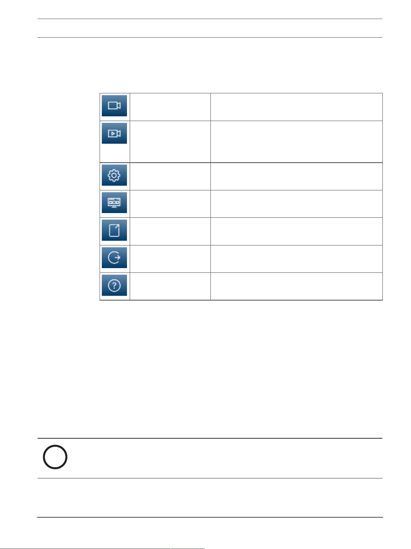
The application bar displays the following icons:
Live Click this icon to view the live video stream.
Playback Click this icon to play back recorded sequences.
This link is only visible if a storage medium has been
configured for recording. (With VRM recording, this
option is not active.)
Configuration Click this icon to configure the device.
Dashboard Click this icon to see detailed system information.
Links Click this icon to navigate to the Bosch download store.
Logout Click this icon to log out of the device.
Click this icon to get context-sensitive help for the page
you are browsing.
2.1 Live
The Live page is used to display the live video stream and control the unit.
2.2 Playback
The Playback page is used for playing back recorded sequences.
2.3 Configuration
The Configuration page is used to configure the unit and the application interface.
Making Changes
Each configuration screen shows the current settings. You can change the settings by entering
new values or by selecting a predefined value from a list field.
Not every page has a Set button. Changes to pages without a Set button are set immediately.
If a page does show a Set button, you must click the Set button for a change to take effect.
i
Notice!
Save each change with the associated Set button.
Clicking the Set button saves the settings only in the current field. Changes in any other fields
are ignored.
Some changes only take effect after the unit is rebooted. In this case, the Set button changes
to Set and Reboot.
1. Make the desired changes.

8 en | System overview DINION 7100i IR
2023-06 | V02 | F.01U.390.686
User manual
Bosch Security Systems B.V.
2. Click the Set and Reboot button. The camera reboots and the changed settings are
activated.
2.4 Dashboard
The Dashboard page is used to display detailed information about the device.
The Dashboard is only visible in the application bar if the Show 'Dashboard' option is enabled
by a service-level user in the Configuration -> Web Interface -> Appearance page.
DINION 7100i IR Operation via the browser | en 9
Bosch Security Systems B.V.
User manual
2023-06 | V02 | F.01U.390.686
3 Operation via the browser
3.1 Live page
After the connection is established, the Live page is initially displayed. It shows the live video
image on the right of the browser window. Depending on the configuration, various text
overlays may be visible on the live video image.
Other information may also be shown next to the live video image. The items shown depend
on the settings on the 'Live' functions page.
Connection
In the Connection group, you can configure the Stream option.
Video stream selection
To view a live stream of the selected video channel:
1. On the left side of the browser, expand the Connection group if necessary.
2. Click the Stream drop-down arrow to see the options.
Select the stream you wish to view.
Digital I/O
Depending on the configuration of the unit, the alarm input and the output are displayed next
to the image. Expand the Digital I/O group if necessary.
The alarm symbol is for information and indicates the status of an alarm input:
– The symbol lights when the input alarm is active.
The alarm output allows the operation of an external device (for example, a light switch or a
door opener).
– To activate the output, click the checkmark symbol.
– The symbol lights when the output is activated.
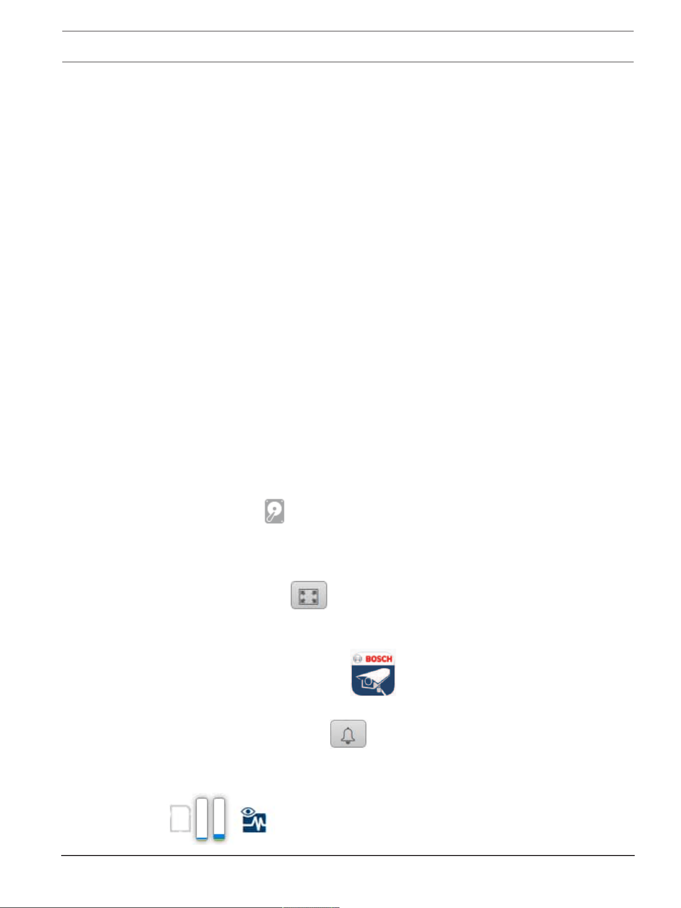
Recording status
The hard drive icon
below the live camera image changes during an automatic recording.
The icon lights up and displays a moving graphic to indicate a running recording. If no
recording is taking place, a static icon is displayed.
Full-screen display
Click the full-screen icon
to view the selected stream in full-screen mode; press Esc
on the keyboard to return to the normal viewing window.
Start Video Security app
To start the Video Security app, click
.
Show latest event
Click the Show latest event icon
to watch the last recorded important events.
The Playback page opens.
Storage, CPU and network status
10 en | Operation via the browser DINION 7100i IR
2023-06 | V02 | F.01U.390.686
User manual
Bosch Security Systems B.V.
When accessing the unit with a browser, the local storage, processor and network status icons
are shown in the upper right of the window.
When a local storage card is available, the memory card icon changes color (green, orange or
red) to indicate the local storage activity. If you hover over this icon with the mouse the
storage activity is shown as a percentage.
If you hover over the middle icon, the CPU load is shown.
If you hover over the right-hand icon, the network load is shown.
This information can help with problem solving or when fine tuning the unit. For example:
– if the storage activity is too high, change the recording profile,
– if the CPU load is too high, change the VCA settings,
– if the network load is too big, change the encoder profile to reduce bitrate.
Status icons
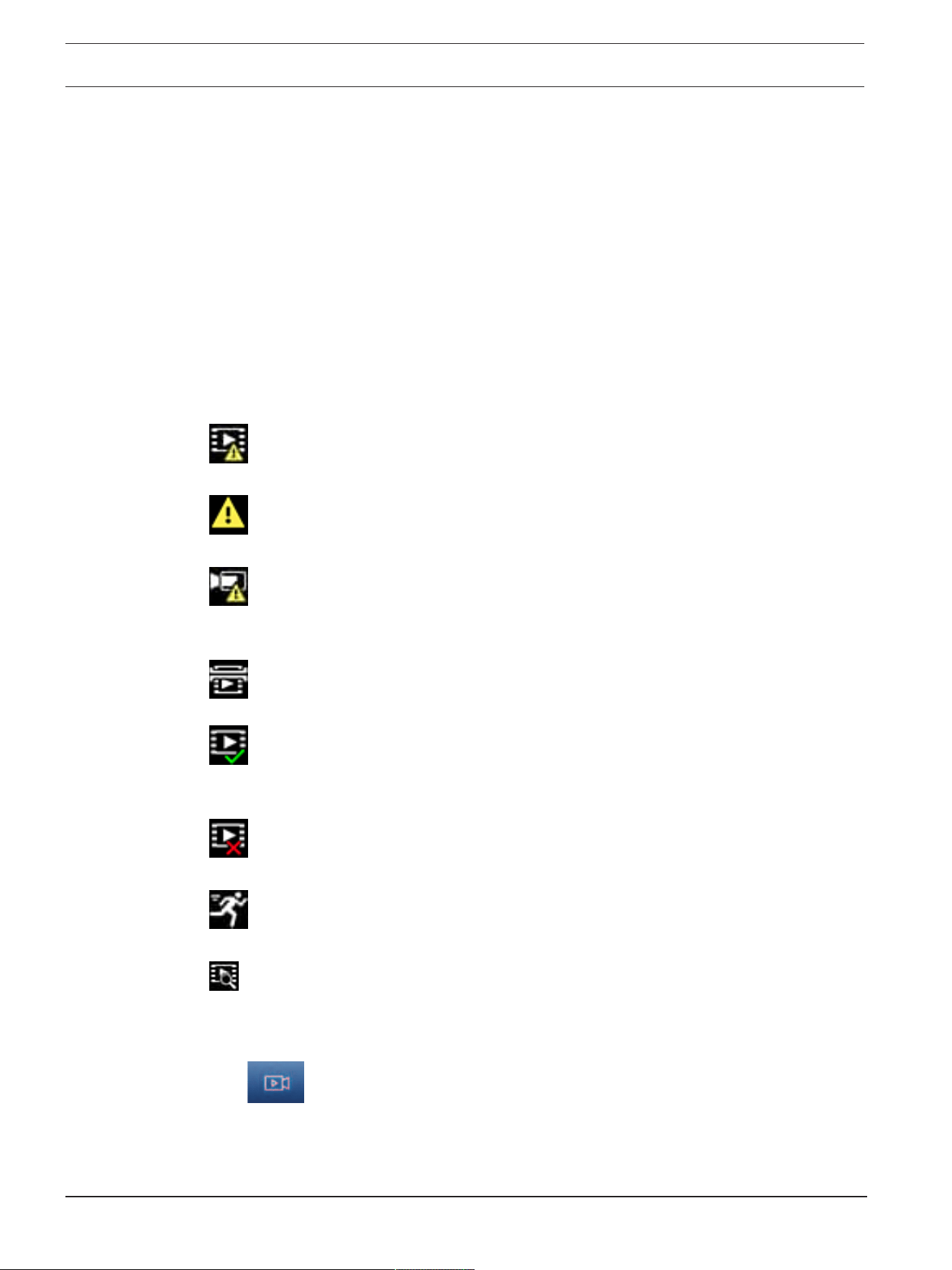
Various overlays in the video image provide important status information. The overlays provide
the following information:
Decoding error
The frame might show artifacts due to decoding errors.
Alarm flag
Indicates that an alarm has occurred.
Communication error
A communication error, such as a connection failure to the storage medium, a protocol
violation or a timeout, is indicated by this icon.
Gap
Indicates a gap in the recorded video.
Watermark valid
The watermark set on the media item is valid. The color of the check mark changes according
to the video authentication method that has been selected.
Watermark invalid
Indicates that the watermark is not valid.
Motion alarm
Indicates that a motion alarm has occurred.
Storage discovery
Indicates that recorded video is being retrieved.
3.2 Playback page
Click
Playback in the application bar to view, search or export recordings. This link is
only visible when a direct iSCSI or memory card is configured for recording (with Video
Recording Manager (VRM) recording this option is not active).
On the left side of the screen, there are four groups:
– Connection

DINION 7100i IR Operation via the browser | en 11
Bosch Security Systems B.V.
User manual
2023-06 | V02 | F.01U.390.686
– Search
– Export
– Track list
3.2.1 Selecting the recording stream
Expand the Connection group on the left side of the browser.
To view a recording stream:
– Click the Recording drop-down arrow to see the options.
– Select one of the numbered recording streams.
3.2.2 Searching for recorded video
Expand the Search group on the left side of the browser.
– To limit the search to a particular time range, enter the date and times for the start and
stop points.
– Select an option from the drop-down box to define a search parameter.
– Click Search.
– The results are listed in a new window. Click a result to play it back.
– Click Back to define a new search.
– Click Last results to display the latest search results.
3.2.3 Exporting recorded video
On the left side of the browser, expand the Export group if necessary:
1. Select a track in the track list or in the search results.
2. The start and stop date and time are filled for the selected track. If necessary, change the
times.
3. In the Time lapse drop-down box, select Original, to export the recorded video as its
original, Condensed to export the recorded video condensed to the given output time.
4. In the Location drop-down box, select a target.
5. Click Export to save the video track.
Note:
The target server address is set on the Connectivity>Accounts page.
3.2.4 Track list
The Track list shows all the available recordings.
3.2.5 Controlling playback
The time bar below the video image allows quick orientation. The time interval associated with
the sequence is displayed in the bar in gray. Arrows indicate the position of the image
currently being played back within the sequence.
The time bar offers various options for navigation in and between sequences.
– If required, click in the bar at the point in time at which the playback should begin.
– Change the time interval displayed by clicking the plus or minus icons or use the mouse
scroll wheel. The display can span a range from six months to one minute.
– Click the alarm jump buttons to go from one alarm event to the next or to the previous
one. Red bars indicate the points in time where alarms were triggered.
Controls
Control playback by means of the buttons below the video image.
The buttons have the following functions:
– Start/Pause playback
– Select the playback (forward or backward) speed using the speed regulator

12 en | Operation via the browser DINION 7100i IR
2023-06 | V02 | F.01U.390.686
User manual
Bosch Security Systems B.V.
– Step forward or backward frame-by-frame when paused (small arrows)
3.3 Dashboard
The Dashboard page shows information on 4 topics:
– Device status
– Recording status
– Connection Status
– Services
You can also download a .JSON file with information about the device:
1. At the bottom of the page, locate the Export button
2. Click the Export button
3. Select a location in your hard drive to store the file

DINION 7100i IR Configuration | en 13
Bosch Security Systems B.V.
User manual
2023-06 | V02 | F.01U.390.686
4 Configuration
4.1 General
4.1.1 Identification
Device name
Assign a unique name to assist in identification. This name simplifies the management of
multiple devices in more extensive systems.
The name is used for remote identification, for example, in the event of an alarm. Choose a
name that makes it as easy as possible to identify the location unambiguously.
Device ID
Each device should be assigned a unique identifier that can be entered here as an additional
means of identification.
Video name
Each video channel can be given a name. Click the + sign to add an extra line.
Host name
Enter the host name registered for the device.
Initiator extension
Add text to an initiator name to make identification easier in large iSCSI systems. This text is
added to the initiator name, separated from it by a full stop. (You can see the initiator name in
the System Overview page.)
Click Set to apply the changes.
4.1.2 User Management
A password prevents unauthorized access to the device. You can use different authorization
levels to limit access.
Proper password protection is only guaranteed when all higher authorization levels are also
protected with a password. Therefore, you must always start from the highest authorization
level when assigning passwords.
You can define and change a password for each authorization level if you are logged into the
“service” user account.
Authentication modes
The section Authentication modes provides information about the authentication modes set
in the camera. A checkmark appears in the checkbox to the left of the mode if the mode is set.
If the mode is not set, the phrase “No certificate installed” appears to the right of the mode
name.
This device has three authentication modes:
– Password indicates a password is set for the camera. It prevents unauthorized access to
the device, and can use different authorization levels to limit access.
Proper password protection is only guaranteed when all higher authorization levels are
also protected with a password. Therefore, you must always start from the highest
authorization level when assigning passwords.
You can define and change a password for each authorization level if you are logged into
the service user account.
– Certificate. A check mark in this check box indicates that at least one certificate is loaded
onto the device.
The Trusted certificate is a root certificate for Bosch Security Systems that proves that
the device meets the following criteria:
– It originates from a Bosch factory that is a secure environment.

14 en | Configuration DINION 7100i IR
2023-06 | V02 | F.01U.390.686
User manual
Bosch Security Systems B.V.
– It has not been tampered with.
The Trusted certificate is issued by Escrypt. Escrypt is a Bosch company and Certificate
Authority (CA).
– Active Directory server (AD FS). A check mark in this check box indicates that the device
uses an active directory server.
Click Set to apply the changes.
Creating a new user
To create a new user, click Add in the section below Authentication modes.
In the box User, fill in the fields:
1. User name, Enter a name with a minimum of 5 and a maximum of 31 characters.
2. Group, select the appropriate authorization level:
– live is the lowest authorization level. At this level, it is only possible to view the live
video image, and switch between the different live image displays.
– user is a middle authorization level. At this level, it is possible to operate the device
and playback recordings, but configuration changes are not possible.
– IVA configuration is a middle authorization level. At this level, it is only possible to
configure VCA, but access is available to all user level functions like PTZ and Replay.
– service is the highest authorization level. Entering the correct password gives access
to all the functions, and allows all configuration settings to be changed.
3. Type, select either:
– Password for a new password.
Use a minimum of 8 and a maximum of 19 characters. The password must have
upper-case and lower-case letters, one or more numerical digits and one or more of
these special characters ! ? ” # $ % ( ) { } [ ] * - = . , ; ^ _ | ~ \
Special characters such as space @ : < > ‘ & + are not valid.
In this case, enter the new password a second time to eliminate typing mistakes.
– Certificate for a certificate that the new user is authorized to use.
4. Click Set to confirm and create a new user.
To edit a password
To edit a password, click the pencil icon to the right of the column Type for the appropriate
User name.
4.1.3 Date/Time
Date format
Select the required date format from the dropdown menu.
Device date/Device time
i
Notice!
Make sure that recording is stopped before synching to the PC.
If there are multiple devices operating in your system or network, it is important to
synchronize their internal clocks. For example, it is only possible to identify and correctly
evaluate simultaneous recordings when all units are operating on the same time.
1. Enter the current date. Since the unit time is controlled by the internal clock, there is no
need to enter the day of the week - it is added automatically.
2. Enter the current time or click the Sync to PC button to copy your computer's system
time to the camera.

DINION 7100i IR Configuration | en 15
Bosch Security Systems B.V.
User manual
2023-06 | V02 | F.01U.390.686
Note: It is important that the date/time is correct for recording. An incorrect date/time setting
could prevent correct recording.
Device time zone
Select the time zone in which the system is located.
Daylight saving time
The internal clock can switch automatically between normal and daylight saving time (DST).
The unit already contains the data for DST switch-overs for many years in advance. If the date,
time and zone have been set up correctly, a DST table is automatically created.
If you decide to create alternative daylight saving time dates by editing the table, note that
values occur in linked pairs (DST start and end dates).
First, check the time zone setting. If it is not correct, select the appropriate time zone and
click Set.
1. Click Details to edit the DST table.
2. Click Generate to fill the table with the preset values from the unit.
3. Click one of the entries in the table to make changes. The entry is highlighted.
4. Click Delete to remove the entry from the table.
5. Choose other values from the list boxes under the table, to change the selected entry.
Changes are immediate.
6. If there are empty lines at the bottom of the table, for example after deletions, add new
data by marking the row and selecting values from the list boxes.
7. When finished, click OK to save and activate the table.
Time server address
The camera can receive the time signal from time server using various time server protocols,
and then use it to set the internal clock. The unit polls the time signal automatically once every
minute.
Enter the IP address of a time server here.
You can choose to have the DHCP server give a time server date by selecting the Overwrite by
DHCP option.
Time server type
Select the protocol that is supported by the selected time server.
– Select Time protocol if the server uses the protocol RFC868.
– The SNTP protocol supports a high level of accuracy and is required for special
applications and subsequent function extensions.
– Select TLS protocol if the server uses the RFC 5246 protocol.
– Select Off to disable the time server.
Click Set to apply the changes.
4.2 Web Interface
4.2.1 Appearance
You can adapt the appearance of the web interface and change the website language to meet
your requirements.
Website language
Select the language for the user interface.
The default language is English.
After setting the new language, the page refreshes automatically. The GUI now displays field
names and options, as well as OSD messages, in the selected language.

16 en | Configuration DINION 7100i IR
2023-06 | V02 | F.01U.390.686
User manual
Bosch Security Systems B.V.
Show VCA metadata
When video content analysis (VCA) is activated, additional information is displayed in the live
video stream. With the MOTION+ analysis type, for example, the sensor fields in which motion
is recorded are marked with yellow rectangles.
Using video analytics the outlines of detected objects are displayed in following colors:
– Red: Objects that generate an alarm event under the current settings appear on the
camera image inside a red outline.
– Orange: An object that has triggered one alarm event but does not generate another
appears inside an orange outline (example: object has crossed a line). During forensic
search, an object that triggers an alarm event has an orange outline from the beginning.
– Yellow: Objects that are detected as moving but do not generate an alarm event under
the current settings appear inside a yellow outline.
Show VCA trajectories
When this option is activated, the trajectories (motion lines of objects) from the video content
analysis are displayed in the live video image if a corresponding analysis type is activated. The
trajectory is shown as a green line following the object base point.
Show overlay icons
Select this check box to show overlay icons on the live video image.
Show VCA items
Select this checkbox to show VCA items on the live video image.
Shows alarm fields, lines and routes configured for the video analytics in the following colors:
– Green: Fields, lines and routes used in a task are displayed in green. They can be edited
but not deleted.
– Red: Fields, lines and routes currently in alarm mode are displayed in red.
Show 'Dashboard'
Select this checkbox to enable the Dashboard in the application bar.
Secure cookies
Select this checkbox to secure the cookies sent through the camera.
i
Notice!
If cookies are secured, authentication forwarding to MPEG ActiveX and the Video Security
App is prohibited.
HTTP referrer check
Click this option to disable HTTP referrer checking. This option is enabled by default.
The HTTP referrer check works as a protection against a CSRF (Cross-site request forgery)
attack.
If a use case requires not sending the HTTP referrer, you can disable this option. In this
situation, you might require other mitigations against CSRF attacks.
Video player
Select the type of player to be used for live mode viewing.
Latency mode
Select the required latency mode:
– Low delay: Default mode. Provides marginal buffering to display fluent video under
normal network conditions.
– Smooth video: Allows the buffer to automatically adjust to cover network jitter, inducing
higher latency.

DINION 7100i IR Configuration | en 17
Bosch Security Systems B.V.
User manual
2023-06 | V02 | F.01U.390.686
– No buffering: Shows video as it is received by the decoder with minimum latency. Allows
the video to jerk if there is network jitter.
Note: Latency mode is only usable with MPEG-ActiveX in Internet Explorer. This browser is no
longer supported.
Video buffer
The value shown is calculated from the Latency mode setting. It cannot be changed.
JPEG resolution
Specify the size of the JPEG image on the Live page. The options are Small, Medium, Large
(720p), Maximum, and Resource based (default).
Note: Resource based will apply the best resolution possible based on the available
resources.
JPEG interval
You can specify the interval at which the individual images should be generated for the M-
JPEG image on the Live page.
Enter a time interval (in milliseconds). The default is 0.
JPEG quality
You can specify the quality at which the JPEG images appear on the Live page.
This option is only available if JPEG resolution is not set to Resource based.
Click Set to apply the changes.
4.2.2 'Live' functions
You can adapt the Live page functions to meet your requirements. Choose from a variety of
different options for displaying information and controls.
1. Select the check boxes for the functions to be displayed on the Live page. The selected
elements are checked.
2. Check to see if the desired items are shown.
Transmit audio
When selected, the audio from the camera (if set to On on the Audio page) is sent to the
computer. This setting applies only to the computer on which the selection is made.
Transmitting audio data requires additional network bandwidth.
Auto logout time [min]
Set a time frame (in minutes) for the automatic logout. Default value is 0 (no automatic
logout).
Show alarm inputs
The alarm inputs are displayed next to the video image as icons along with their assigned
names. If an alarm is active, the corresponding icon changes color.
Show alarm outputs
Alarm outputs are shown next to the video image as icons along with their assigned names. If
an output is switched, the icon changes color.
Allow snapshots
Specify whether the icon for saving individual images should be displayed below the live
image. Individual images can only be saved if this icon is visible.
Allow local recording
Specify whether the icon for saving video sequences locally should be displayed below the live
image. Video sequences can only be saved locally on your hard disk if this icon is visible.

18 en | Configuration DINION 7100i IR
2023-06 | V02 | F.01U.390.686
User manual
Bosch Security Systems B.V.
Path for JPEG and video files
Enter the path for the storage location of individual images and video sequences saved from
the Live page.
Video file format
Select a file format for the live page display. The MP4 format does not include metadata.
Click Set to apply the changes.
4.3 Connectivity
4.3.1 Cloud services
Remote Portal
Operation
The operation mode determines how the camera communicates with the Remote Portal.
– Select On to poll the server constantly.
– Select Off to block polling.
– Select Re-register to different account if you want to register the camera to another
Remote Portal account.
Connectivity state
This field indicates the device's connectivity state with Remote Portal.
– If the device is registered and the operation mode is set to On, the state will indicate that
the device is Connected (to the cloud service).
Note: The Visit Remote Portal button will become active.
– If the device is not registered or the operation mode is set to Off, the state will indicate
that the device is Not available.
Note: The Register button will become active only if you have not registered the device to the
Remote Portal.
Partner services
Stratocast
Enter the Stratocast Registration code to connect with the Genetec’s Stratocast cloud.
Click Register to activate the account.
4.3.2 Accounts
Four separate accounts can be defined for posting and recording export.
Type
Select the account type.
Account name
Enter an account name to be shown as the target name.
IP address
Enter the IP address for an FTP server.
Login
Enter your login name for the account server.
Password
Enter the password that gives access to the account server. Click Check to confirm that it is
correct.

DINION 7100i IR Configuration | en 19
Bosch Security Systems B.V.
User manual
2023-06 | V02 | F.01U.390.686
Path
Enter an exact path to post the images on the account server. Click Browse... to browse to the
required path.
Maximum bit rate
Enter the maximum bit rate in kbps that will be allowed when communicating with the
account.
Encryption
Tick the box to use a secure FTP over TLS connection.
Click Set to apply the changes.
4.3.3 DynDNS
A dynamic Domain Name Service (DNS) allows you to select the unit via the Internet using a
host name, without having to know the current IP address of the unit. You can enable this
service here. To do this, you must have an account with one of the dynamic DNS providers and
you must register the required host name for the unit on that site.
Note:
For information about the service, registration process and available host names refer to the
provider.
Enable DynDNS
Use the drop-down menu to select On or Off to enable or disable DynDNS.
Provider
Select your dynamic DNS Provider from the drop-down list.
Host name
Enter the host name registered for the unit.
User name
Enter the user name you registered.
Password
Enter the password you registered.
Force registration now
Force the registration by transferring the IP address to the DynDNS server. Entries that change
frequently are not provided in the Domain Name System. It is a good idea to force the
registration when setting up the device for the first time. Only use this function when
necessary and no more than once a day, to avoid the possibility of being blocked by the
service provider. To transfer the IP address of the device, click the Register button.
Status
The status of the DynDNS function is displayed here for information purposes; these settings
cannot be changed.
Click Set to apply the changes.
4.4 Camera
4.4.1 Installer Menu
Sensor mode
Multiple Sensor mode options are available to configure based on the local mains power
frequency and scene requirements.
Some types of light can show flickering in the image when the frame rate is not synchronized
with the mains power frequency.
Make sure that the selected sensor mode frame rate is in line with the mains power frequency.

20 en | Configuration DINION 7100i IR
2023-06 | V02 | F.01U.390.686
User manual
Bosch Security Systems B.V.
Select the preferred maximum frame rate based on the scene requirements.
For devices with HDRX:
The HDRX sensor modes provide much improved dynamic range over the 50/60fps high
frame rate modes, and provides maximum detail in all scenes, even in challenging scenes with
dark and bright areas in the same shot.
In the Enhance menu, the High dynamic range setting allows further options to optimize the
HDRX mode for fast motion or maximum dynamic range. The default HDRX - Motion
optimized setting ensures an improved dynamic range without the downsides of traditional
HDR which makes this default setting ideal for most scenes, even with fast motion.
The 50/60fps mode does not support HDRX and therefore has a limited dynamic range. This
mode can be used if very fast moving objects are captured in the scene for which 25/30fps
would result in missing objects or too few frames of the object of interest.
Note: As exposure time is not directly related to the device's frame rate, there is no need to
select a high frame rate to ensure images without motion blur. The 25/30fps HDR X mode is
just as capably as the 50/60fps high frame rate mode.
Image rotation
This device has four image rotation options:
– 0°
– 90° - upright
– 180°
– 270° - upright
Select the option that best suits the device mounting position.
The upright modes (90° and 270°) are good for vertical scenes, such as hallways or
perimeters. When these options are selected, the aspect ratio and the signaling to the
interfaces change (example, 16:9 to 9:16).
If the device is mounted in its normal position, select 0°.
The end result is shown in the Live preview.
Mirror image
Select On to output a mirror image of the device picture.
The end result is shown in the Live preview.
Electronic image stabilization
Select On to activate Electronic image stabilization to compensate for any vibration or
oscillation effects in the device.
By stabilizing the image and reducing unwanted scene movements, Electronic image
stabilization minimizes detail loss in the scene and optimizes bitrate usage.
The image crop percentage for Electronic image stabilization can be configured in the Lens
Wizard menu.
Lens Wizard
The camera view is configured with the Lens Wizard.
You can use the wizard to configure the field of view and focus of the lens.
– Live Video window
– The Live Video window shows a live video stream. Click in the live video window to
move the device and center its field of view at the selected position. The device also
automatically levels the horizon.
– On some browsers, such as Firefox and Chrome, a rectangle can be drawn on the
live video window. The device automatically centers the field of view at the selected
position, levels the horizon and also zooms in.

DINION 7100i IR Configuration | en 21
Bosch Security Systems B.V.
User manual
2023-06 | V02 | F.01U.390.686
– Set lens to default position
– Select Default to set the lens to its default position.
– Optical zoom
– Use the slider to adjust the optical zoom.
– Autofocus
– Select either Local Range (preferred selection) or Full Range (backup selection) to
automatically focus the image.
– Focus position
– Use the slider to adjust the focus position. The focus position automatically adjusts
to the autofocus.
– Focus indicator
– The Focus indicator shows a value related to the focus quality of the image. The
higher the value, the more in focus the image will be.
– Lens
– Indicates the lens type in use.
– IR-corrected lens
– Click the checkbox to activate or deactivate IR correction function.
The setting of the lens mode is crucial to ensure optimal performance. In daylight
operation, the IR-corrected mode is not required. In dark environments where the
majority of light is provided by the IR illuminators, the lens should be set to IR-
corrected mode. Otherwise, if sufficient ambient light is available, disable the IR-
corrected mode. An incorrect lens setting could result in improper focusing.
– Electronic image stabilization crop [%]
– Use the slider to adjust the percentage of the image cropped to compensate for any
movements caused by vibration or oscillation. A higher image crop percentage allows
for greater movement compensation.
Camera LED
Click the Enabled or Disabled check-box to switch the Camera LED on or off.
Select Auto disable to let the camera determine when the LED should be switched off.
The camera LED activates when powering on the camera for the first time. The LED
deactivates automatically after 5min.
Reboot device
Click the Reboot button to restart the device. The entire reboot sequence takes approximately
60seconds.
Restore settings
Click Restore to restore all settings, except network settings, to their defaults.
Note: Clicking this button also clears the service-level password. Operators must reset the
password before doing anything else.
Factory defaults
Click Defaults to restore all settings, including passwords and network settings, to their
defaults.
Note: Clicking this button also clears the service-level password. Operators must reset the
password before doing anything else.
4.4.2 Display Stamping
Various overlays or stamps in the video image provide important supplementary information.
These overlays can be enabled individually and arranged on the image in a clear manner.
The drop-down menus below allow the configuration of the individual stamping options. The
respective sample windows show a preview of the configured text and background styles.

22 en | Configuration DINION 7100i IR
2023-06 | V02 | F.01U.390.686
User manual
Bosch Security Systems B.V.
Click Set to apply the changes.
Global configuration
i
Notice!
These options can also be configured individually for all stamping settings.
Any changes to the global configuration settings will be applied to all stamping settings!
– Stamping size
Select the desired font size of the overlays on the OSD: Normal, Large or Custom.
Select Custom to enable the Font size (‰) field.
– Text color
Select the color for the alarm message to be displayed in.
– Background color
Select the background color for the alarm message to be displayed in.
If you have enabled the Transparent background option, the background color is not
displayed in the OSD.
Camera name stamping
– Position
Select the position of the camera name overlay in the drop-down box. It can be displayed at
the Top, at the Bottom, or at a position of choice using the Custom option, or it can be set to
Off for no overlay information.
If the Custom option is selected, enter values in the X and Y position fields.
– Stamping size
Select the desired font size of the overlays on the OSD: Normal, Large or Custom.
Select Custom to enable the Font size (‰) field.
– Text color
Select the color for the alarm message to be displayed in.
– Background color
Select the background color for the alarm message to be displayed in.
If you have enabled the Transparent background option, the background color is not
displayed in the OSD.
Optionally, tick the Underlay with full-width bar box to place a full-width background-bar
beneath the time stamp.
i
Notice!
Camera / video names can be changed under General > Identification.
Logo stamping
– Enable
Check this box to enable Logo stamping.
– Position (XY)
This parameter becomes visible if Logo stamping is enabled.
Insert the values for the X and Y coordinates to specify the logo's position.
– Logo

DINION 7100i IR Configuration | en 23
Bosch Security Systems B.V.
User manual
2023-06 | V02 | F.01U.390.686
To place a logo on the image, select and upload an uncompressed .bmp file with a maximum
size of 128x128 pixels and 256 colors to the camera.
Time stamping
– Position
Select the position of the camera name overlay in the drop-down box. It can be displayed at
the Top, at the Bottom, or at a position of choice using the Custom option, or it can be set to
Off for no overlay information.
If the Custom option is selected, enter values in the X and Y position fields.
– Stamping size
Select the desired font size of the overlays on the OSD: Normal, Large or Custom.
Select Custom to enable the Font size (‰) field.
– Text color
Select the color for the alarm message to be displayed in.
– Background color
Select the background color for the alarm message to be displayed in.
If you have enabled the Transparent background option, the background color is not
displayed in the OSD.
Alarm mode stamping
– Position
Select the position of the camera name overlay in the drop-down box. It can be displayed at
the Top, at the Bottom, or at a position of choice using the Custom option, or it can be set to
Off for no overlay information.
If the Custom option is selected, enter values in the X and Y position fields.
– Stamping size
Select the desired font size of the overlays on the OSD: Normal, Large or Custom.
Select Custom to enable the Font size (‰) field.
– Alarm message
Enter the message to be displayed on the image in the event of an alarm. The maximum text
length is 32characters.
– Text color
Select the color for the alarm message to be displayed in.
– Background color
Select the background color for the alarm message to be displayed in.
If you have enabled the Transparent background option, the background color is not
displayed in the OSD.
Stream security
Select from the Video authentication drop-down box a method for verifying the integrity of
the video.
If you select Watermarking, all images are marked with an icon. The icon indicates if the
sequence (live or saved) has been manipulated.
If you want to add a digital signature to the transmitted video images to ensure their integrity,
select one of the cryptographic algorithms for this signature.
Set the Signature interval [s] for the selected authentication method.
Click Set to apply the changes.

24 en | Configuration DINION 7100i IR
2023-06 | V02 | F.01U.390.686
User manual
Bosch Security Systems B.V.
4.4.3 Positioning
The Positioning feature describes the location of the camera and the perspective in the
camera’s field of view.
Perspective information is essential to Video Analytics, as it enables the system to compensate
for the illusory smallness of distant objects.
Only through use of perspective information is it possible to distinguish objects such as
persons, bicycles, cars and trucks, and accurately compute their real size and speeds as they
move through 3D space.
However, to calculate perspective information accurately, the camera must be directed at a
single, flat horizontal plane. Multiple and inclined planes, hills, stairs can falsify perspective
information and produce incorrect object information such as size and speed.
Mounting position
The mounting position describes the perspective information that is also often called
calibration.
In general, the mounting position is determined by the parameters of the camera such as
height, roll angle, tilt angle, and focal length.
The height of the camera must always be entered manually. Whenever possible, roll angle and
tilt angle are provided by the camera itself. The focal length is provided, if the camera has a
built-in lens.
Tilt angle [°]
Enter the tilt angle if the value is not determined by the camera.
The tilt angle describes the angle between the horizontal and the camera.
A tilt angle of 0° means that the camera is mounted parallel to the ground.
A tilt angle of 90° means that the camera is mounted vertically in bird’s eye view perspective.
The flatter the tilt angle is set, the less accurate the estimate of object sizes and speeds will
be. The settings must be between 0° and 90°. Estimates are no longer possible when you have
reached 0°.
Roll angle [°]
Enter the roll angle if the value is not determined by the camera.
The roll angle describes the angle between the roll axis and the horizontal plane. The angle
can deviate from the horizontal by up to 45°.
Height [m]
Enter the height in meters of the position of the camera.
The height describes the vertical distance from the camera to the ground plane of the
captured image. Typically the elevation of the mounted camera above the ground.
Focal length [mm]
Enter the focal length in millimeters of the position of the camera if the value is not
determined by the camera.
The focal length is determined by the lens. The shorter the focal length, the wider the field of
view. The longer the focal length, the narrower the field of view and the higher the
magnification.
Show sensor values...
Click to automatically see the camera parameters, for example, Tilt angle [°], Roll angle [°]
and Focal length [mm]. These calibration values are measured by the device sensors. Click OK
to transfer them to the Positioning settings page.
Sketch
Click to improve the automatic calibration. The Sketch-based calibration window is displayed.

DINION 7100i IR Configuration | en 25
Bosch Security Systems B.V.
User manual
2023-06 | V02 | F.01U.390.686
The Sketch functionality offers an additional, half-automatic calibration method. This
calibration method allows you to describe the perspective in the camera’s field of view by
drawing vertical lines, ground lines, and ground angles in the camera image and entering the
correct size and angle. Use the Sketch functionality if the result of the automatic calibration is
not sufficient.
You can also combine this manual calibration with the values for roll angle, tilt angle, height
and focal length calculated by the camera or entered manually.
Select the Calculate check box to obtain the roll angle, tilt angle, height and focal length from
the sketched calibration elements - vertical lines, ground lines and angles - you have placed in
the device.
Clear the Calculate check box to enter a value manually or to refresh to the values provided by
the device itself.
Assisted calibration with Configuration Manager
Calibration leverages data from the device's internal sensors and/or direct user input.
With Configuration Manager (version 7.60 or higher) the device can be calibrated using the
map-based calibration feature, which allows fast and easy calibration by marking ground
points on the map and image.
Alternatively, the user can still resort to the Sketch-based calibration to manually input the
calibration values.
Refer to the Configuration Manager Online help content to learn more about assisted
calibration methods.
Calibrating cameras using the Sketch-based calibration window
To determine non-automatically set values:
1. Enter the value for tilt angle, roll angle, height and focal length if the value is known, for
example, by measuring the height of the camera above the ground, or reading the focal
length from the lens.
2. For each value that is still unknown, select the Calculate check box, then place a
calibration element on the camera image. Use these calibration elements to trace
individual outlines of the displayed environment in the camera image and define the
position and size of these lines and angles.
– Click to place a vertical line across the image.
A vertical line corresponds to a line that is perpendicular to the ground plane, such
as a door frame, edge of a building or a lamp post.
– Click to place a line across the ground in the image.
A line on ground corresponds to a line that is on the ground plane, such as a road
marking.
– Click to place an angle on the ground in the image.
The angle on ground represents an angle lying on the horizontal ground plane, such
as the corner of a carpet or parking bay markings.
3. Adjust the calibration elements to the situation:
– Enter the real size of a line or angle. To do this, select the line or angle, then enter
the size in the corresponding box.
Example: You have placed a line on ground across the lower side of an automobile.
You know that the automobile is 4m long. Enter 4m as the length of the line.
– Adjust the position or length of a line or angle. To do this, drag the line or angle or
move the end points to the desired position in the camera image.
– Remove a line or angle. To do this, select the line or angle, then click the trash can
icon.

26 en | Configuration DINION 7100i IR
2023-06 | V02 | F.01U.390.686
User manual
Bosch Security Systems B.V.
Note:
Blue lines indicate calibration elements added by you.
White lines represent the element as it should be positioned on the camera image based
on the current calibration results or the determined calibration data.
i
Notice!
If the distance to the camera (geolocation) is not relevant, it is enough to determine height
and focal length in relation to each other. This allows a simple calibration by marking 2-3
persons ‑ each with a vertical line ‑ and setting their size. 1,80m (71 in.) for all is sufficient.
Use at least one person in the front and one person in the background of the image for best
results.
Coordinate system
Select the coordinate system and enter the appropriate values in the additional input fields
that appear depending on the coordinate system selected.
The Coordinate system feature describes the position of the camera in a local Cartesian or
the global WGS 84 coordinate system. The camera and the objects tracked by the video
analytics are displayed on a map.
Cartesian
The Cartesian coordinate system describes each point in the space by a combination of the
position on three orthogonal axes X, Y and Z. A right-handed coordinate system is used, where
X and Y span the ground plane and Z describes the elevation of the ground plane.
X [m]
The location of the camera on the ground on the X-axis.
Y [m]
The location of the camera on the ground on the Y-axis.
Z [m]
The elevation of the ground plane. To determine the elevation of the camera, add the Z [m]
value and the Height [m] value of the camera.
Azimuth [°]
The orientation of the camera in a counter-clockwise angle starting with 0° in the east (WGS
84) or on the X-axis (Cartesian). If the camera is directed towards the north (WGS 84) or the
Y-axis (Cartesian), the azimuth is 90°.
WGS 84
The WGS 84 coordinate system is a spherical coordinate system description of the world and
used in many standards including GPS.
Latitude
Latitude is the north-south position of the camera in the spherical coordinate system WGS 84.
Longitude
Longitude is the east-west position of the camera in the spherical coordinate system WGS 84.
Ground level [m]
The elevation of the ground above sea level. To determine the elevation of the camera, add the
Ground level [m] value and the Height [m] value of the camera.
Azimuth [°]
The orientation of the camera in a counter-clockwise angle starting with 0° in the east (WGS
84) or on the X-axis (Cartesian). If the camera is directed towards the north (WGS 84) or the
Y-axis (Cartesian), the azimuth is 90°.
Click Set to apply the changes.

DINION 7100i IR Configuration | en 27
Bosch Security Systems B.V.
User manual
2023-06 | V02 | F.01U.390.686
4.4.4 Scene Mode
A scene mode is a collection of image parameters that are set in the device when that
particular mode is selected (installer menu settings are excluded). Several pre-defined modes
are available for typical scenarios. After a mode has been selected, additional changes can be
made through the user interface.
Current mode
i
Notice!
Some modes might behave differently in single exposure sensor mode and HDR sensor mode.
Standard
This mode is optimized for most standard scenes both indoor and outdoor.
Sodium lighting
This mode can be used in applications with street (sodium vapor) lighting. A special white
balance algorithm compensates for the yellow / orange color of the lights.
Fast movement
This mode is used for monitoring fast moving objects like cars in traffic scenes. Motion
artifacts are minimized and the image is optimized for a sharp and detailed picture in color
and monochrome.
Sensitivity boost
This mode provides maximum sensitivity in low light scenes by using longer exposure times,
resulting in bright images even in extreme low light. It can introduce motion blur because of
the slow shutter speed.
Backlight
In this mode Intelligent Auto Exposure is enabled, it automatically optimizes the exposure for
the moving objects in the scene. It is ideal for cameras monitoring an entrance with people
moving in front of a bright background.
Vibrant
This mode provides a more vivid image with increased contrast, sharpness and saturation.
This is at the expense of slightly reduced color accuracy and higher bit-rate.
Color only
In this mode the camera will not switch to monochrome mode at low light levels. It can be
used for scenarios where color images are required day and night, like in city surveillance.
Sports and gaming
This mode is for high-speed capture, and improved color rendition and sharpness.
Retail
This mode has improved color rendition and sharpness with reduced bandwidth requirements.
LPR
This mode is optimized for capturing reflective number plates at high speed in combination
with IR-lighting. Short shutter speeds and low maximum gain providing sharp and high
contrast images of license plates.
Notes:
– During night-time, in monochrome mode only, the license plates will be clearly visible
while the rest of the scene will be dark.

28 en | Configuration DINION 7100i IR
2023-06 | V02 | F.01U.390.686
User manual
Bosch Security Systems B.V.
– Depending on device positioning, car speed and used IR beam, customization of shutter
time and maximum gain is required.
– IR illumination is required.
Mode ID
The name of the selected mode is displayed.
Copy mode to
Select the mode from the drop-down menu to which you wish to copy the active mode.
Restore Mode Defaults
Click Restore Mode Defaults to restore the factory default modes.
4.4.5 Color
Brightness (0...255)
Adjust the brightness with the slider from 0 to 255.
Contrast (0...255)
Adjust the contrast with the slider from 0 to 255.
Saturation (0...255)
Adjust the color saturation with the slider from 0 to 255.
White balance
Select the appropriate white balance mode from the drop-down list.
– Basic auto mode allows the camera to continually adjust for optimal color reproduction
using an average reflectance method. This is useful for indoor light sources and for
colored LED light illumination.
– Standard auto mode allows the camera to continually adjust for optimal color
reproduction in an environment with natural light sources.
– Sodium lamp auto mode allows the camera to continually adjust for optimal color
reproduction in an environment with sodium vapor light sources (street lighting).
– In Manual RGB mode, the Red, Green, and Blue gain can be set manually to a desired
position.
Apply white balance
Click Hold to put ATW on hold and save the current color settings. The mode changes to
manual.
The table below identifies the options available in the field White balance and the additional
fields that appear depending on the options selected.
Option in field “White
balance”
Additional fields for
configuration
NOTES
Basic auto The three fields R-gain, G-gain, and B-
gain only appear when the hold button
is pushed.
Standard auto
Sodium lamp auto
Manual RGB R-gain
G-gain
B-gain
4.4.6 ALC (Automatic Level Control)
ALC mode
Select the appropriate automatic high-level control mode from the drop-down list.

DINION 7100i IR Configuration | en 29
Bosch Security Systems B.V.
User manual
2023-06 | V02 | F.01U.390.686
– Fluorescent 50 Hz
– Fluorescent 60 Hz
– Standard
ALC level
Adjust the video output level.
Select the range within which the ALC will operate. A positive value is more useful for low-
light conditions; a negative value is more useful for very bright conditions.
Priority - dark vs. bright
Use the slider to configure the ALC to prioritize either darker spots in the scene (scene
average) or brighter spots in the scene (scene peak). For example, prioritizing the control of
bright spots in a scene is useful for capturing images that contain sources of illumination, such
as car headlights.
ALC speed
Select the speed of the video level control loop from the dropdown list.
Maximum gain [dB]
Adjust the decibels of maximum gain with the slider.
Exposure
Select the appropriate exposure speed.
– Select Automatic exposure to allow the device to set the optimum shutter speed
automatically. The device tries to maintain the default shutter speed as long as the light
level of the scene permits.
– Select Fixed exposure to set a fixed shutter speed.
Select the shutter speed for fixed exposure.
Maximum shutter [s]
Select a value in this field as the maximum speed of the shutter when the camera is in
Automatic exposure mode. The limit on the shutter speeds improves the motion performance.
Default shutter [s]
Select a default shutter speed. The default shutter improves the motion performance in auto
exposure mode.
Fixed shutter [s]
Select the Fixed shutter [s] for fixed exposure. (The values available depend on the value set
for the ALC mode).
P iris
The lens mode can be set to Standard or Manual.
– In the Standard mode, the F-stop of the lens is adjusted automatically for best
performance.
– In the Manual mode, the precise F-stop of the lens can be selected with the slider.
Iris priority - open vs. closed
Use the slider to adjust the iris opening to the specific requirements of the scene.
An open iris increases local sharpness.
A closed iris increases depth of field, which allows you to keep objects of interest in focus.
In scenes where a change of the iris opening affects the gain, closing the iris causes more
video noise and increases bandwidth. Increased motion blur may also occur when the iris is
more closed.

30 en | Configuration DINION 7100i IR
2023-06 | V02 | F.01U.390.686
User manual
Bosch Security Systems B.V.
Day/night
Select the appropriate mode from the drop-down list.
– Auto - the device switches the IR cut-off filter on and off depending on the scene
illumination level.
– Color - the device always produces a color signal regardless of light levels.
– Monochrome - the IR cut-off filter is removed, giving full IR sensitivity.
Day-to-night switchover
Adjust the slider to set the video level at which the device in Automatic exposure mode
switches from color to monochrome operation.
A low (negative) value means that the device switches to monochrome at a lower light level. A
high (positive) value means that the device switches to monochrome at a higher light level.
i
Notice!
The device has a mechanism to prevent oscillation between switching from day to night and
night to day continuously when the device is in Auto.
In case of frequent oscillations, the device will stay progressively longer in night mode. At a
certain point, the device will stop oscillating and enter permanent night mode.
Resetting this behavior ensures a shorter night mode. This can be useful, for example, to
account for changing conditions or for when the device is moved to a different location.
To reset this behavior, you need to switch the Day/night mode from Auto to a different
option (Color or Monochrome), and then revert to Auto.
4.4.7 Illuminator
Illuminator function
The information about the installed illuminator module is displayed on top of this page.
The device automatically adapts the IR beam angle to match the field of view of the lens.
Select the control setting for the illuminator:
– On: the illuminator is always on.
– Off: the illuminator is always off.
– Auto: the device automatically switches between illuminator modes.
– Intelligent: the device automatically optimizes the IR output to the scene to make sure
the image is captured with the correct exposure level and minimal loss of detail.
The Intensity level can still be used to set the maximum intensity value for the
illuminator.
Intensity level
Set the intensity of the IR beam.
4.4.8 Enhance
High dynamic range
The High dynamic range mode selection becomes available when a High dynamic range (HDR
or HDRX) sensor mode is set in the Sensor mode in the Installer Menu. Set the High
dynamic range mode to:
– Off - The device is in single exposure mode and the user does not have an increased
dynamic range through HDRX. This setting is not suggested as it offers no benefits over
HDR X - Motion optimized (larger dynamic range) or 50/60fps sensor modes (high
frame rate).
– HDR X - Motion optimized (default setting) - This mode enables high quality video-
capture of fast moving objects in scenes with a large dynamic range. The device takes two
different readouts from a single exposure to capture both details in the highlights and

DINION 7100i IR Configuration | en 31
Bosch Security Systems B.V.
User manual
2023-06 | V02 | F.01U.390.686
shadows of the scene, not depending on multiple exposures. This results in an improved
dynamic range compared to non-HDR modes with maximum clarity on moving objects as
there is no risk of HDR blending artifacts.
– HDR X - Optimized DR - This mode should be used for even greater dynamic range
requirements. It adds another fast exposure on top of the HDR X - Motion optimized
mode combining the benefits from HDR X - Motion optimized and traditional HDR.
– HDR X - Extreme DR - Further increases performance to an absolute maximum by adding
another fast exposure on top of the HDR X - Motion optimized mode at an even greater
HDR ratio. This mode combines the benefits from HDR X - Motion optimized and
traditional HDR. Due to the maximum HDR ratio, there is a larger risk of HDR artifacts in
the scene and on moving objects.
Backlight compensation
– Select Off to switch off backlight compensation.
– Select On to capture details in high-contrast and extremely bright-dark conditions.
Intelligent Defog
With the Intelligent Defog mode feature, visibility can be improved significantly when viewing
foggy or other low-contrast scenes.
– Select Extreme to activate an Intelligent Defog mode with enhanced defog capabilities.
– Select Auto to activate the Intelligent Defog feature automatically as needed.
– Select Off to disable the feature.
Contrast enhancement
Use the slider to adjust the contrast enhancement.
Sharpness level
Use the slider to adjust the sharpness level. The zero position of the slider corresponds to the
factory default level.
A low (negative) value makes the picture less sharp. Increasing sharpness brings out more
detail. Extra sharpness can enhance the details of license plates, facial features and the edges
of certain surfaces but will increase bandwidth requirements.
Temporal noise filtering
Adjust the Temporal noise filtering level. The higher the value, the more noise filtering.
Spatial noise filtering
Adjusts the Spatial noise filtering level. The higher the value, the more noise filtering.
4.4.9 Scene Mode Scheduler
The scene mode scheduler is used to determine which scene mode should be used during the
day and which scene mode should be used during the night.
1. Select the mode you wish to use during the day from Marked range drop-down box.
2. Select the mode you wish to use during the night from Unmarked range drop-down box.
3. Use the two slider buttons to set the Time ranges.
To set the Marked range as the single mode of the device, select the complete time range.
The text “Always” will appear after the Marked range menu.
For more information on the different scene modes, refer to the Scene Mode chapter.
Click Set to apply the changes.
4.4.10 Encoder Streams
When this menu is accessed while the device is recording, the following message appears at
the top of the page: “Recording is currently active. At ‘Active profile’ the stream profile used
for recording is displayed, and overrules the ‘Non-recording profile’.”

32 en | Configuration DINION 7100i IR
2023-06 | V02 | F.01U.390.686
User manual
Bosch Security Systems B.V.
Stream limits (H.264/H.265)
Select the maximum stream resolution as provided per stream.
Stream limits is a mandatory selection to pre-assign the maximum available resolution for each
of the four H.264/H.265 streams. If a lower resolution is selected, you will be more flexible in
streaming options on the second and third stream. The fourth JPEG stream always shows the
maximum resolution available in the camera.
Stream 1 always runs at the maximum selected resolution in stream limits. On stream 2 and 3,
you can select various downscaled resolutions.
Stream prioritization
Select the stream that should not drop any frame.
Coding standard
Select the coding standard you want to use for the stream.
Active profile
Active profile shows the profile that is in use and can be set differently per stream
If no edge recording or VRM recording is active, the device switches to the Non-recording
profile. Please refer to section Non-recording profile.
Select one of the following profiles for each stream:
Profile number Description
Profile 1 For a high resolution image, the video bit rate and frame quality are
adjusted to ensure that the picture quality is the priority.
Profile 2 For a high resolution image, the video bit rate and frame quality are
adjusted to a median profile for everyday use.
Profile 3 For a high resolution image, the video bit rate and frame quality are
adjusted to ensure that the bit rate is the priority.
Profile 4 For a low resolution image, the video bit rate and frame quality are
adjusted to ensure that the picture quality is the priority.
Profile 5 For a low resolution image, the video bit rate and frame quality are
adjusted to a median profile for everyday use.
Profile 6 For a low resolution image, the video bit rate and frame quality are
adjusted to ensure that the bit rate is the priority.
Profile 7 Ideal for encoding on a DSL uplink where bit rate limitations are critical.
Profile 8 Ideal for encoding on a 3G uplink where bit rate limitations are critical.
Stream 1 always runs at maximum selected resolution in stream limits. On stream 2 and 3, you
can select various downscaled resolutions.
Non-recording profile
Select one of the resolutions from the drop-down menu for each stream.
If you activate the recording function, the active profile switches from Non-recording profile
to Active profile.
The Active profile follows the scheduled profiles under Recording Profiles. Please refer to
section Recording Profiles.
This behavior is only applicable when using Bosch recording solutions, including edge
recording or VRM recording. Third-party recording solutions might use the Non-recording
profile.
DINION 7100i IR Configuration | en 33
Bosch Security Systems B.V.
User manual
2023-06 | V02 | F.01U.390.686
If no edge recording or VRM recording is active, the active profile is managed via the drop-
down of Non-recording profile.
If edge recording or VRM recording is active, the active profile is managed via the menu in
Recording Profiles. Please refer to section Recording Profiles.
Click Frame and bit rate test to see when and if a specific stream will drop frames.
Encoder Profile
To access the Encoder Profile configuration window for the individual streams, click the edit
(pencil) button next to the respective Active profile or Non-recording profile sections.
!
Caution!
The profiles are rather complex. They include a large number of parameters that interact with
one another, so it is generally best to use the default profiles.
Change the profiles only once you are fully familiar with all the configuration options.
Profile name
If required, enter a new name for the profile.
Video resolution
Select one of the available video resolution options from the drop-down menu.
Frame rate
The Frame rate slider determines the interval at which images are encoded and transmitted.
This can be particularly advantageous with low bandwidths. The frame rate is displayed next
to the slider.
The frame rate is the result from the maximum or base frame rate divided by the value of the
encoding interval (for example, with a base frame rate of 30 fps and an encoding interval of 6,
the encoded frame rate is 5 fps).
Advanced Settings
If necessary, use the advanced settings to adapt the I-frame quality and the P-frame quality to
specific requirements. The setting is based on the H.264 quantization parameter (QP).
GOP structure
Select the required structure for the group of pictures, depending on whether you place
greater priority on having the lowest possible delay or using as little bandwidth as possible.
I-frame distance
Use the slider to set the distance between I-frames to Auto or to between 3 and 255. An entry
of 3 means that every third image is an I-frame. The lower the number, the more I-frames are
generated.
Min. P-frame QP
The Quantization Parameter (QP) specifies the degree of compression and thus the image
quality for every frame. The lower the QP value, the higher the encoding quality. A higher
quality produces a higher data load. Typical QP values are between 18 and 30. Define the
lower limit for the quantization of the P-frames here, and thus the maximum achievable quality
of the P-frames.
I/P-frame delta QP
This parameter sets the ratio of the I-frame QP to the P-frame QP. For example, you can set a
lower value for I-frames by moving the slide control to a negative value. Thus, the quality of the
I-frames relative to the P-frames is improved. The total data load will increase, but only by the
portion of I-frames.

34 en | Configuration DINION 7100i IR
2023-06 | V02 | F.01U.390.686
User manual
Bosch Security Systems B.V.
To obtain the highest quality at the lowest bandwidth, even in the case of increased
movement in the picture, configure the quality settings as follows:
1. Observe the coverage area during normal movement in the preview images.
2. Set the value for Min. P-frame QP to the highest value at which the image quality still
meets your needs.
3. Set the value for I/P-frame delta QP to the lowest possible value. This is how to save
bandwidth and memory in normal scenes. The image quality is retained even in the case
of increased movement since the bandwidth is then filled up to the value that is entered
under Maximum bit rate.
Click Default to return the profile to the factory default values.
Click Set to apply the changes.
Frame and bit rate test
Click to open the Frame and bit rate test window.
Select the checkboxes for the individual streams to obtain the respective frame and bit rate
values.
4.4.11 Encoder Statistics
This section gives the user information about the bit rate of the device. For each scene, it is
possible to determine the best target/max bit rate through the graphic shown.
Stream
Identifies the current stream.
Zoom
Identifies the current zoom factor of the camera (1x, 2x, 4x, or 8x).
Averaging period
Select the appropriate averaging period as a means of stabilizing the long term bit rate.
4.4.12 Privacy Masks
Privacy Masks block specific areas of a scene from being seen in the camera's field of view.
This can be useful when public spaces are in the coverage area or monitoring will be limited to
a particular zone.
Pattern
Select the color of the mask as it will appear in the live video: Auto, Black, Gray, White or
Custom color.
When Auto is selected, for one or more masks with a similar background, these will try to
blend with the surrounding color. If the backgrounds have different colors, the masks will
average between the colors.
A total of eight (8) masks can be in view at the same time.
To configure a Privacy mask:
– Select the mask number from the drop-down list.
– Click the plus button.
– Adjust the mask in the image:
– Double-click on the edges to add or remove nodes.
– Click and drag the nodes to position them correctly.
– Check the Enabled check box to activate the related mask.
– Click the Set button to apply the related changes.
To delete a Privacy mask:
– Select the mask number from the drop-down list.

DINION 7100i IR Configuration | en 35
Bosch Security Systems B.V.
User manual
2023-06 | V02 | F.01U.390.686
– Click the trashcan icon.
– Click the Set button to apply the changes.
4.4.13 Audio
You can set the gain of the audio signals to suit your specific requirements. The live video
image is shown in the window to help you check the audio source. Your changes are effective
immediately.
If you connect via Web browser, you must activate the audio transmission on the 'Live'
functions page. For other connections, the transmission depends on the audio settings of the
respective system.
The audio signals are sent in a separate data stream parallel to the video data, and so increase
the network load. The audio data is encoded according to the selected format and requires
additional bandwidth. If you do not want any audio data to be transmitted, select Off.
Audio
Enable or disable the audio recording option.
Audio input
Select the required audio input from the dropdown list:
– Line In: Line level input
– Microphone: Microphone level input with 2.5VDC (4mA) supply voltage for external
microphone
Input volume/Microphone volume
Adjust the audio level with the slider(s). Adjust so that the indicator does not go into the red
zone.
Line Out
Adjust the audio level with the slider(s). Adjust so that the indicator does not go into the red
zone.
Recording format
Select a format for audio recording. The default value is 48 kbps. You can select 80 kbps,
G.711 or L16 depending on the required audio quality or sampling rate.
AAC audio technology is licensed by Fraunhofer IIS.
(http://www.iis.fraunhofer.de/amm/
)
AAC bit rate
Select the required AAC bit rate.
Send audio
Audio can be sent via the Send audio button if the unit supports audio. The button activates
the audio backchannel connection.
1. Click and hold the Send audio button to send an audio signal to the unit.
2. Release the button to stop sending audio.
You must have a speaker or similar connected to the line out of the camera in order to send
the audio.
Click Set to apply the changes.
4.4.14 Pixel Counter
The number of horizontal and vertical pixels covered by the highlighted area is displayed
below the picture. With these values you can check whether the requirements for specific
functions, for example, identification tasks, are fulfilled.
1. Click Freeze to freeze the camera image if the object that you want to measure is moving.

36 en | Configuration DINION 7100i IR
2023-06 | V02 | F.01U.390.686
User manual
Bosch Security Systems B.V.
2. To reposition a zone, place the cursor over the zone, hold down the mouse button and
drag into position.
3. To change the shape of a zone, place the cursor over the edge of the zone, hold down the
mouse button and drag the edge of the zone to the required position.
4.5 Recording
Images can be recorded to an appropriately configured iSCSI system or, for devices with an
SD slot, locally to an SD card.
SD cards are the ideal solution for shorter storage times and temporary recordings. They can
be used for local alarm recording or to improve the overall reliability of video recording.
For long-term authoritative images use an appropriately sized iSCSI system.
Two recording tracks are available (Recording 1 and Recording 2). The encoder streams and
profiles can be selected for each of these tracks for both standard and alarm recordings.
Ten recording profiles are available where these recording tracks can be defined differently.
These profiles are then used for building schedules.
A Video Recording Manager (VRM) can control all recording when accessing an iSCSI system.
The VRM is an external program for configuring recording tasks for video servers.
4.5.1 Storage Management
Device manager
The Device manager indicates if storage is controlled locally or by a VRM system.
An external Video Recording Manager (VRM) system for the unit is configured via the
Configuration Manager.
Recording media
Select a media tab to connect to the available storage media.
iSCSI Media
To use an iSCSI system as the storage medium, a connection to the desired iSCSI system is
required to set the configuration parameters.
The storage system selected must be available on the network and completely set up. It must
have an IP address and be divided into logical drives (LUNs).
1. Enter the IP address of the required iSCSI destination in the iSCSI IP address field.
2. If the iSCSI destination is password protected, enter the password into the Password
field.
3. Click Read.
– The connection to the IP address is established.
The Storage overview field displays the logical drives.
Managed storage media
Local Media
A microSD card inserted in the camera can be used for local recording.
4 If the microSD card is password protected, enter the password into the Password field.
The Storage overview field shows the local media.
Note: microSD card recording performance is highly dependent on the speed (class) and
performance of the microSD card. It is recommended to use an Industrial microSD card.

DINION 7100i IR Configuration | en 37
Bosch Security Systems B.V.
User manual
2023-06 | V02 | F.01U.390.686
Local storage
To activate the ANR settings, Recording 1 must be assigned to an iSCSI target and Recording
2 to a local storage.
This function enables recording to the iSCSI target. If there is a network disconnection, the
video is recorded to the local storage. When the network is recovered, the video recorded to
the local storage is transferred to the iSCSI target and completes the missing information.
Dual micro SD
When two micro SD cards are installed, they can be combined to function in these modes:
– Redundant: The two micro SD cards record the same data, for redundancy purposes.
– On the first micro SD card, select recording track Rec. 1 or Rec. 2.
– On the second micro SD card, select the other recording track.
– Failover: One of the micro SD cards can be used as a backup for the other micro SD card.
– On the first micro SD card, select recording track Rec. 1 or Rec. 2.
– On the second micro SD card, select the same recording track as the first micro SD
card.
– With the second micro SD card selected, click Edit and check the Use as failover
checkbox.
– Extended: The recording is saved in one micro SD card until it is full and then would be
saved in the other micro SD card. When this last one is full, the recording would go back
to the first one and overwrite the previously saved recording.
– On the first micro SD card, select recording track Rec. 1 or Rec. 2.
– On the second micro SD card, select the same recording track.
The recording settings of the recording tracks Rec. 1 and Rec. 2 can be configured under
Recording Profiles.
When using Redundant mode, the two recording tracks are used, so it is not possible to use
the iSCSI Media or VRM recording in parallel.
Activating and configuring storage media
Available media or iSCSI drives must be transferred to the Managed storage media list,
activated, and configured for storage.
Note:
An iSCSI target storage device can only be associated with one user. If a target is being used
by another user, ensure that the current user no longer needs the target before decoupling
that user.
1. In the Storage overview section, double-click a storage medium, an iSCSI LUN or one of
the other available drives.
– The medium is added as a target in the Managed storage media list.
– Newly added media is shown as Not active in the Status column.
2. Click Set to activate all media in the Managed storage media list.
– The Status column shows all media as Online.
3. Check the box in the Rec. 1 or Rec. 2 column to specify the recording tracks to be
recorded on the target selected.
Deactivating storage media
A storage medium in the Managed storage media list can be deactivated. It is then no longer
used for recordings.
1. Click a storage medium in the Managed storage media list to select it.
2. Click Remove below the list. The storage medium is deactivated and removed from the
list.

38 en | Configuration DINION 7100i IR
2023-06 | V02 | F.01U.390.686
User manual
Bosch Security Systems B.V.
Formatting and wiping storage media
Formatting the storage media can be necessary to delete all data and recreate a valid file
structure to be usable.
All recordings on a storage medium can be deleted at any time. Check the recordings before
deleting and back-up important sequences on the computer's hard drive.
1. Click a storage medium in the Managed storage media list to select it.
2. Click Edit below the list.
3. Click Format in the new window to delete all recordings in the storage medium.
4. Click OK to close the window.
Wiping the storage media deletes all data without recreating a valid file structure.
To wipe the recordings from the storage media:
1. Click a storage medium in the Managed storage media list to select it.
2. Click Edit below the list.
3. Click Wipe in the new window to wipe the recordings in the storage medium.
4. Click Close to close the window.
Click Set to apply the changes.
4.5.2 Recording Profiles
A recording profile contains the characteristics of the tracks that are used for recording. These
characteristics can be defined for ten different profiles. The profiles can then be assigned to
days or times of day on the Recording Scheduler page.
Each profile is color-coded. The names of the profiles can be changed on the Recording
Scheduler page.
To configure a profile click its tab to open its settings page:
– To copy the currently visible settings to other profiles, click Copy Settings. A window
opens to select the target profiles for the copied settings.
– If you change a profile’s settings, click Set to save.
– If necessary, click Default to return all settings to their factory defaults.
Stream profile settings
Select the encoder profile setting that is to be used with stream 1 and 2 when recording. This
selection is independent of the selection for live stream transmission. (The properties of the
encoder profiles are defined on the Encoder Streams page.)
Settings for selected recordings
Recording includes
Select what is to be included in the recordings:
– Audio: If audio is not enabled, Off is shown. Click on Off and the page is redirected to
the Audio section.
– Metadata.
You can specify whether, in addition to video data, audio data and metadata (for example
alarms, VCA data and serial data) should also be recorded. Including metadata could make
subsequent searches of recordings easier but it requires additional storage capacity.
!
Caution!
Without metadata, it is not possible to include video content analytics in recordings.
Select the mode for standard recordings:

DINION 7100i IR Configuration | en 39
Bosch Security Systems B.V.
User manual
2023-06 | V02 | F.01U.390.686
– Continuous: the recording proceeds continuously. If the maximum recording capacity is
reached, older recordings are overwritten automatically.
– Pre-alarm: recording takes place in the pre-alarm time, during the alarm and during the
post-alarm time only.
– Off: no automatic recording takes place.
Stream
Select the stream to be used for standard recordings:
– Stream 1
– Stream 2
– I-frames only
Alarm recording
Select a period for the Pre-alarm time from the list box. The RAM option allows the pre-alarm
recording ring buffer to be stored in RAM as long as it fits, depending on bit rate settings. This
avoids writing to the SD card or iSCSI. The pre alarm ring is written to storage only on alarm.
Select a period for the Post-alarm time from the list box.
Alarm stream
Select the stream to be used for alarm recordings:
– Stream 1
– Stream 2
– I-frames only
Check the encoding interval and bit rates from profile: box and select an encoder profile to
set the associated encoding interval for alarm recording.
Export to account
To send standard H.264 or H.265 files to the target address, select an account and check
Export from memory.
If the target has not yet been defined, click Configure accounts to jump to the Accounts page
where the server information can be entered.
Alarm triggers
Select the alarm type that is to trigger an alarm recording:
– Alarm input
– Analysis alarm
Select the Virtual alarm sensors that are to trigger a recording, via RCP+ commands or alarm
scripts, for example.
Configure accounts
Sends you to the Accounts page.
Copy Settings
You can copy the settings from one profile to another with the Copy Settings button. Select
the target profile and click OK.
Default
The default values are restored.
Click Set to apply the changes.
4.5.3 Maximum Retention Time
Recordings are overwritten when the retention time entered here has expired.
4 Enter the required retention time in days for each recording track.
Once the storage unit is full, the previous recording will be overwritten.

40 en | Configuration DINION 7100i IR
2023-06 | V02 | F.01U.390.686
User manual
Bosch Security Systems B.V.
Click Set to apply the changes.
4.5.4 Recording Scheduler
The recording scheduler allows you to link the created recording profiles to the days and
times at which the camera's images are to be recorded. Schedules can be defined for
weekdays and for holidays.
Weekdays
Assign as many time periods (in 15-minute intervals) as needed for any day of the week. Move
the mouse cursor over the table - the time is displayed.
1. Click the profile to be assigned in the Time periods box.
2. Click a field in the table and, while holding down the left mouse button, drag the cursor
across all of the fields to be assigned to the selected profile.
3. Click the No recordings profile in the Time periods box to deselect the intervals.
4. Click Select All to select all of the intervals to be assigned to the selected profile.
5. Click Clear All to deselect all of the intervals.
6. When finished, click Set to save the settings to the device.
Holidays
Define holidays whose settings will override the settings for the normal weekly schedule.
1. Click the Holidays tab. Days that have already been defined are shown in the table.
2. Click Add. A new window opens.
3. Select the desired From date from the calendar.
4. Click in the To box and select a date from the calendar.
5. Click OK to accept the selection which is handled as a single entry in the table. The
window closes.
6. Assign the defined holidays to the recording profile as described above.
7. To delete a user-defined holiday, click on the trashcan of the respective holiday.
Click Set to apply the changes.
Time periods
Change the names of the recording profiles listed in the Time periods box.
1. Click a profile.
2. Click Rename.
3. Enter the new name and click Rename again.
Recording status
The graphic indicates the recording activity. An animated graphic is displayed when recording
is taking place.
Activating recording
After completing configuration, activate the recording schedule and start scheduled recording.
Once activated, the Recording Profiles and the Recording Scheduler are deactivated and the
configuration cannot be modified. Stop scheduled recording to modify the configuration.
1. Click Start to activate the recording schedule.
2. Click Stop to deactivate the recording schedule. Recordings that are currently running are
interrupted and the configuration can be modified.
Click Set to apply the changes.
4.5.5 Recording Status
Details of the recording status are displayed here for information. These settings cannot be
changed.

DINION 7100i IR Configuration | en 41
Bosch Security Systems B.V.
User manual
2023-06 | V02 | F.01U.390.686
4.5.6 Recording Statistics
The bit rate of the recorded video (blue) and other data (grey), such as audio and metadata,
are shown in the graphic.
Recording
Identifies the current recording profile (1 or 2).
Zoom
Identifies the current zoom factor of the camera (1x, 2x, 4x, or 8x).
Averaging period
Select the appropriate averaging period as a means of stabilizing the long term bit rate.
4.5.7 Image Posting
Save individual JPEG images on an FTP server at specific intervals.
JPEG
Image size
Select the size of the JPEG images that are to be sent from the camera. JPEG resolution
corresponds to the highest setting from the two data streams.
File name
Select how file names are created for the individual images that are transmitted.
– Overwrite: The same file name is always used and any existing file will be overwritten by
the current file.
– Increment: A number from 000 to 255 is added to the file name and automatically
incremented by 1. When it reaches 255, it starts again from 000.
– Date/time suffix: The date and time are automatically added to the file name. When
setting this parameter, make sure that the date and time of the device are always set
correctly. For example, the file snap011005_114530.jpg was stored on October 1, 2005 at
11:45 and 30 seconds.
VCA overlays
If you have enabled the display of VCA overlays on the Appearance page, select the VCA
overlays check box to have the overlays also visible in the JPEG image.
Posting interval
Enter the interval in seconds at which the images are sent to an FTP server. Enter zero for no
images to be sent.
Target
Select the target account for JPEG posting.
i
Notice!
You must configure an account in order to have functionality for Image Posting. Click on
Configure accounts to do so.
Click Set to apply the changes.
4.5.8 SD Card Status
This section identifies the details about the SD card installed in the device:
– Manufacturer
– Product
– Size
– State
– Lifespan.

42 en | Configuration DINION 7100i IR
2023-06 | V02 | F.01U.390.686
User manual
Bosch Security Systems B.V.
For non-industrial SD cards, the lifespan options are not available.
Lifespan alarm
Set the alarm warning to a defined percentage of the lifespan. The alarms can be given as:
– An audio alarm
– An e-mail
– A warning through the Video Management System
If a SD card is not installed, ‘SD card not found’ is shown.
i
Notice!
Bosch recommends the use of industrial micro SD cards with health monitoring.
4.6 Alarm
4.6.1 Alarm Connections
In the event of an alarm, the unit can automatically connect to a pre-defined IP address. The
unit can contact up to ten IP addresses in the order listed until a connection is made.
Connect on alarm
Select On so that the unit automatically connects to a pre-defined IP address in the event of
an alarm.
Select Follows input 1 so that the unit maintains the connection for as long as an alarm exists
on alarm input 1.
Auto-connect
Select On to automatically re-establish a connection to one of the previously specified IP
addresses after each reboot, connection breakdown, or network failure.
Number of destination IP address
Specify the numbers of the IP addresses to be contacted in the event of an alarm. The unit
contacts the remote locations one after the other in the numbered sequence until a
connection is made.
Destination IP address
For each number, enter the corresponding IP address for the desired remote station.
Destination password
If the remote station is password protected, enter the password here.
Only ten passwords can be defined here. Define a general password if more than ten
connections are required. The unit connects to all remote stations protected by the same
general password. To define a general password:
1. Select 10 in the Number of destination IP address list box.
2. Enter 0.0.0.0 in the Destination IP address field.
3. Enter the password in the Destination password field.
4. Set the user password of all the remote stations to be accessed using this password.
Setting destination 10 to the IP-address 0.0.0.0 overrides its function as the tenth address to
try.
Video transmission
If the unit is operated behind a firewall, select TCP (HTTP port) as the transfer protocol. For
use in a local network, select UDP.
To enable multicast operation, select UDP for the Video transmission parameter here and on
the Network Access page.

DINION 7100i IR Configuration | en 43
Bosch Security Systems B.V.
User manual
2023-06 | V02 | F.01U.390.686
Note:
In the event of an alarm, a larger network bandwidth is sometimes required for additional
video streams (if multicast operation is not possible).
Stream
Select a stream to be transmitted.
Remote port
Select an appropriate browser port depending on the network configuration.
The ports for HTTPS connections are only available if SSL encryption is set to On.
Video output
If a hardware receiver is used, select the analog video output to which the signal should be
switched. If the destination device is unknown, select First available. This places the image on
the first video output with no signal.
The connected monitor only displays images when an alarm is triggered.
Note:
Refer to the destination unit documentation for more information on image display options
and available video outputs.
Decoder
If a split image is set for the selected video output, select a decoder to display the alarm
image. The decoder selected determines the position in the split image.
SSL encryption
SSL encryption protects data used for establishing a connection, such as the password. By
selecting On, only encrypted ports are available for the Remote port parameter. SSL
encryption must be activated and configured on both sides of a connection.
The appropriate certificates must also have been uploaded. (Certificates can be uploaded on
the Certificates page.)
Configure and activate encryption for media data (such as video, metadata or audio when
available) on the Encryption page (encryption is only available if the appropriate license is
installed).
Audio
Select On to transmit the audio stream with an alarm connection.
Click Set to apply the changes.
4.6.2 Video Content Analysis (VCA)
This device has an integrated video analytics suite of AI-driven software, which detects and
analyzes changes in the picture using image processing algorithms. Such changes can be due
to movements in the device's field of view. Detection of movement can be used to trigger an
alarm and to transmit metadata.
Various VCA configurations can be selected and adapted to your application, as required.
Configure the VCA setting in the Bosch Configuration Manager.
4.6.3 Audio Alarm
Alarms can be generated based on audio signals. Configure signal strengths and frequency
ranges so that false alarms, for example, machine noise or background noise, are avoided.
Set up normal audio transmission before configuring the audio alarm.
Audio alarm
Select On for the device to generate audio alarms.

44 en | Configuration DINION 7100i IR
2023-06 | V02 | F.01U.390.686
User manual
Bosch Security Systems B.V.
Name
The name makes it easier to identify the alarm in extensive video monitoring systems. Enter a
unique and clear name here.
Signal Ranges
Exclude particular signal ranges in order to avoid false alarms. For this reason the total signal
is divided into 13 tonal ranges (mel scale). Check or uncheck the boxes below the graphic to
include or exclude individual ranges.
Threshold
Set up the threshold on the basis of the signal visible in the graphic. Set the threshold using
the slide control or move the white line directly in the graphic using the mouse.
Sensitivity
Use this setting to adapt the sensitivity to the sound environment and effectively suppress
individual signal peaks. A high value represents a high level of sensitivity.
Click Set to apply the changes.
4.6.4 Alarm Email
Alarm states can be documented by e-mail. The camera automatically sends an e‑mail to a
user-defined e‑mail address. This makes it possible to notify a recipient who does not have a
video receiver.
Send alarm e-mail
Select On for the device to automatically send an alarm e‑mail in the event of an alarm.
Mail server IP address
Enter the IP address of a mail server that operates on the SMTP standard (Simple Mail
Transfer Protocol). Outgoing e‑mails are sent to the mail server via the address entered.
Otherwise, leave the box blank (0.0.0.0).
SMTP port
Select the appropriate SMTP port.
SMTP user name
Enter a registered user name for the chosen mail server.
SMTP password
Enter the required password for the registered user name.
Format
Select the data format of the alarm message.
– Standard (with JPEG): e‑mail with JPEG image file attachment.
– SMS: e‑mail in SMS format to an e‑mail‑to‑SMS gateway without an image attachment.
When a mobile phone is used as the receiver, make sure to activate the e‑mail or SMS
function, depending on the format, so that these messages can be received. Obtain
information on operating your mobile phone from your mobile phone provider.
Image size
Select the size of the JPEG images that are to be sent from the camera.
Attach JPEG from camera
To send a JPEG image from a particular video channel, check the appropriate box.
VCA overlays
Select the VCA overlays check box, to place the outline of the object that triggered an alarm
into the camera image sent as snapshot via e-mail.
Destination address
Enter the e‑mail address for alarm e‑mails here. The maximum address length is 49 characters.

DINION 7100i IR Configuration | en 45
Bosch Security Systems B.V.
User manual
2023-06 | V02 | F.01U.390.686
Sender address
Enter a unique name for the e‑mail sender, for example, the location of the device. This makes
it easier to identify the origin of the e‑mail.
Test e-mail
Click Send Now to test the e‑mail function. An alarm e-mail is immediately created and sent.
Click Set to apply the changes.
4.6.5 Alarm Inputs
Active
Configure the alarm triggers for the unit.
Select N.C. (Normally Closed) if the alarm is to be triggered by opening the contact.
Select N.O. (Normally Open) if the alarm is to be triggered by closing the contact.
Name
Enter a name for the alarm input. This is then displayed below the icon for the alarm input on
the Live page (if configured).
Action
Select a type of action to be performed when an alarm input occurs:
– None
– Monochrome
This switches the camera to the monochrome mode.
– Switch mode
When this is selected, you can select the Scene Mode to be used for the active and
inactive period of the alarm.
Click Set to apply the changes.
4.6.6 Alarm Outputs
Configure the switching behavior of the output.
Select different events that automatically activate an output. For example, turn on a floodlight
by triggering a motion alarm and then turn the light off again when the alarm has stopped.
Idle state
Select Open for the output to operate as a normally open contact, or select Closed if the
output is to operate as a normally closed contact.
Operating mode
Select the way the output works.
For example, if you want an activated alarm to stay on after the alarm ends, select Bistable. If
you wish an activated alarm to stay on for ten seconds for example, select 10s.
Output follows
Select the event that triggers the output.
Output name
The alarm output can be assigned a name here. This name appears on the Live page.
Toggle
Click the button to switch the alarm output manually (for example, for testing purposes or to
operate a door opener).
Click Set to apply the changes.
4.6.7 Auxiliary Power
Auxiliary Power

46 en | Configuration DINION 7100i IR
2023-06 | V02 | F.01U.390.686
User manual
Bosch Security Systems B.V.
Check the Enable '12V OUT' output box to enable connected external devices, such as motion
detectors, with a maximum of 50 mA. The 12V OUT output can be dynamically controlled
through the Alarm Task Editor.
4.6.8 Alarm Task Editor
Editing scripts on this page overwrites all settings and entries on the other alarm pages. This
procedure cannot be reversed.
To edit this page, you should have programming knowledge and be familiar with the
information in the Alarm Task Script Language document and the English language.
As an alternative to the alarm settings on the various alarm pages, enter the desired alarm
functions in script form here. This will overwrite all settings and entries on the other alarm
pages.
1. Click Examples under the Alarm Task Editor field to see some script examples. A new
window opens.
2. Enter new scripts in the Alarm Task Editor field or change existing scripts in line with your
requirements.
3. When finished, click Set to transmit the scripts to the device. If the transfer was
successful, the message Script successfully parsed. is displayed over the text field. If it
was not successful, an error message is displayed with further information.
4.7 Network
The settings on these pages are used to integrate the device into a network. Some changes
only take effect after a reboot. In this case Set changes to Set and Reboot.
1. Make the desired changes.
2. Click Set and Reboot.
The device is rebooted and the changed settings are activated.
4.7.1 Network Services
This page shows an overview of all available network services. Use the checkbox to activate or
deactivate a network service. Click on the settings symbol next to the network service to go to
the settings page for this network service.
Click Set to apply the changes.
Some changes only take effect after the unit is rebooted. In this case, the Set button changes
to Set and Reboot.
4.7.2 Network Access
If the IP address, subnet mask, or gateway address is changed, then the device is only
available under the new addresses after the reboot.
IPv4
Automatic assignment (DHCP)
If the network has a DHCP server for the dynamic assignment of IP addresses, select On to
automatically accept the DHCP-assigned IP address.
For certain applications, the DHCP server must support the fixed assignment between IP
address and MAC address, and must be appropriately set up so that, once an IP address is
assigned, it is retained each time the system is rebooted.
IP address
Enter the desired IP address for the camera. The IP address must be valid for the network.

DINION 7100i IR Configuration | en 47
Bosch Security Systems B.V.
User manual
2023-06 | V02 | F.01U.390.686
Subnet mask
Enter the appropriate subnet mask for the set IP address.
Gateway address
For the device to establish a connection to a remote location in a different subnet, enter the IP
address of the gateway here. Otherwise, this field can remain empty (0.0.0.0).
IPv6
IP address
Enter the desired IP address for the camera. The IP address must be valid for the network.
Prefix length
Enter the appropriate prefix length for the set IP address.
Gateway address
For the device to establish a connection to a remote location in a different subnet, enter the IP
address of the gateway here. Otherwise, this field can remain empty (0.0.0.0).
Additional addresses
This section lists the IPv6 addresses available for use within the network.
Ethernet
The Ethernet options are defined in this section.
DNS server address 1/DNS server address 2
The device is easier to access if it is listed on a DNS server. For example, to establish an
Internet connection to the camera, it is sufficient to enter the name given to the device on the
DNS server as a URL in the browser. Enter the DNS server's IP address. Servers are supported
for secure and dynamic DNS.
Video transmission
If the device is used behind a firewall, TCP (HTTP port) should be selected as the transmission
protocol. For use in a local network, choose UDP.
Multicast operation is only possible with the UDP protocol. The TCP protocol does not
support multicast connections.
HTTP browser port
Select a different HTTP browser port from the list if required. The default HTTP port is 80. To
limit connection to HTTPS, deactivate the HTTP port. To do this, activate the Off option.
HTTPS browser port
To limit browser access to encrypted connections, choose an HTTPS port from the list. The
standard HTTPS port is 443.
The camera uses the TLS 1.2 protocol. Ensure that the browser has been configured to
support this protocol. Also ensure that Java application support is activated (in the Java Plug-
in Control Panel of the Windows Control Panel).
To limit connections to SSL encryption, set the Off option in the HTTP browser port and the
RCP+ port. This deactivates all unencrypted connections allowing connections on the HTTPS
port only.
Minimum TLS version
Select the version for minimum Transport Layer Security (TLS).
Allow HTTP basic authentication
Select On if you want to allow HTTP basic authentication. This is a less secure authentication
option where passwords are transmitted in clear text. This option should only be used if the
network and system are otherwise secured.

48 en | Configuration DINION 7100i IR
2023-06 | V02 | F.01U.390.686
User manual
Bosch Security Systems B.V.
HSTS
Select this option to use the web security policy HTTP Strict Transport Security (HSTS) to
provide secure connections.
RCP+ port 1756
Activating RCP+ port 1756 allows unencrypted connections on this port. To allow only
encrypted connections, set the Off option to deactivate the port.
Discovery port (0 = Off)
Enter the number of the port that you want to discover.
To deactivate the port, enter 0.
Interface mode ETH
If necessary, select the Ethernet link type for interface ETH. Depending on the device
connected, it may be necessary to select a special operation type.
Network MSS [Byte]
Set the maximum segment size for the IP packet's user data here. This gives the option to
adjust the size of the data packets to the network environment and to optimize data
transmission. In UDP mode, comply with the MTU value set below.
Network MTU [Byte]
Specify a maximum value in bytes for the package size (including IP header) to optimize data
transmission.
Click Set to apply the changes.
4.7.3 Advanced
RTSP
RTSP port
If necessary, select a different port for the exchange of the RTSP data from the list. The
standard RTSP port is 554. Select Off to deactivate the RTSP function.
802.1x
Authentication
If a RADIUS server is employed in the network for managing access rights, authentication must
be activated here to allow communication with the unit. The RADIUS server must also contain
the corresponding data.
To configure the unit, you must connect the camera directly to a computer using a network
cable. This is because communication via the network is not enabled until the Identity and
Password parameters have been set and successfully authenticated.
Identity
Enter the name that the RADIUS server is to use for identifying the camera.
Password [EAP-MD5]
Enter the password that is stored in the RADIUS server.
Certificates [EAP-TLS]
If any certificates are already uploaded at the client level or at the server level, they show
here.
Click Configure to be redirected to the Certificates page in order to add or configure any
existing certificates.

DINION 7100i IR Configuration | en 49
Bosch Security Systems B.V.
User manual
2023-06 | V02 | F.01U.390.686
TCP metadata input
TCP port
The device can receive data from an external TCP sender, for example an ATM or POS device,
and store it as metadata. Select the port for TCP communication. Select Off to deactivate the
function.
Sender IP address
Enter a valid Sender IP address.
Syslog
Server IP address
Enter the appropriate IP address of the server.
Server port (0 = Off)
Enter the number of the server port.
Protocol
Select the appropriate protocol: UDP, TCP, or TLS.
LLDP power configuration
This section shows a breakdown of the power values configured for the device.
The Additional power wattage can be adjusted in the respective input field. The default value
is 0.0W.
Click Set to apply the changes.
4.7.4 Network Management
SNMP
The camera supports two versions of Simple Network Management Protocol (SNMP) for
managing and monitoring network components, and can send SNMP messages (traps) to IP
addresses. The unit supports SNMP MIB II in the unified code.
Select either of the options that follow for the SNMP parameter:
– SNMP v1 legacy
– SNMP v3
If you select either of the SNMP version, but do not enter an SNMP host address, the camera
does not send messages (traps) automatically, but only replies to SNMP requests.
Select Off to deactivate the SNMP function.
1. SNMP host address / 2. SNMP host address
If you wish to send SNMP traps automatically, enter the IP addresses of one or two required
target units here.
SNMP v1 legacy
When you select SNMP v1 legacy in the field SNMP, the fields Write community and SNMP
traps appear.
Write community
Type the password for Write community to allow the exchange of data between connected
devices.
SNMP traps
You can select which traps are to be sent.
1. Click Select. A list is opened.
2. Click the checkboxes to select the required traps. All the checked traps will be sent.

50 en | Configuration DINION 7100i IR
2023-06 | V02 | F.01U.390.686
User manual
Bosch Security Systems B.V.
3. Click Set to accept the selection.
SNMP v3
When you select SNMP v3 in the field SNMP, the tabs User and Trap user show.
The same fields show in both tabs.
The SNMP engine ID field also appears, indicating the unique identifier of the SNMP entity.
User name
Enter the appropriate user name.
Authentication protocol
Select the appropriate authentication protocol: None, MD5, or SHA1.
Authentication password
Enter the appropriate password for authentication.
Privacy protocol
Select the appropriate privacy protocol: None, DES, or AES.
Privacy password
Enter the appropriate password.
Read-only
To make this information read-only, select this check box.
Quality of service
The camera offers Quality of Service (QoS) configuration options to ensure fast network
response to PTZ data and images. Quality of Service (QoS) is the set of techniques to manage
network resources. QoS manages the delay, delay variation (jitter), bandwidth, and packet
loss parameters to guarantee the ability of a network to deliver predictable results. QoS
identifies the type of data in a data packet and divides the packets into traffic classes that can
be prioritized for forwarding.
Consult with your network administrator for assistance configuring the Audio, Video, Control,
and the Alarm video settings, and to select the appropriate Post-alarm time.
Post-alarm time has a time period from 0 s [seconds] to 3 h [hours]; 15 s [seconds] is the
default option.
Click Set to apply the changes.
Some changes only take effect after the unit is rebooted. In this case, the Set button changes
to Set and Reboot.
4.7.5 Multicast
The device can enable multiple receivers to receive the video signal simultaneously. The
stream is either duplicated and then distributed to multiple receivers (Multi-unicast), or it is
sent as a single stream to the network, where it is simultaneously distributed to multiple
receivers in a defined group (Multicast).
Multicast operation requires a multicast-enabled network that uses UDP and the Internet
Group Management protocol (IGMPV2). The network must support group IP addresses. Other
group management protocols are not supported. The TCP protocol does not support multicast
connections.
A special IP address from 225.0.0.0 to 239.255.255.255 (classD address) must be configured
for multicast operation in a multicast-enabled network. The multicast address can be the same
for multiple streams, however, it is necessary to use a different port in each case.
The settings must be made individually for each stream. Enter a dedicated multicast address
and port for each stream.

DINION 7100i IR Configuration | en 51
Bosch Security Systems B.V.
User manual
2023-06 | V02 | F.01U.390.686
The video channels can be individually selected for each stream.
Enable
Enable simultaneous data reception on receivers that need to activate the multicast function.
To do this, check the box and enter the multicast address.
Multicast Address
Enter a valid multicast address to be operated in multicast mode (duplication of the data
stream in the network).
With a 0.0.0.0 setting, the encoder for the stream operates in multi-unicast mode (copying of
data stream in device). The camera supports multi-unicast connections for up to five
simultaneously connected receivers.
Duplication of data places a heavy demand on the CPU and can lead to impairment of the
image quality under certain circumstances.
Port
Enter the port address for the stream here.
Streaming
Click the checkbox to activate multicast streaming mode. An activated stream is marked with a
check. (Streaming is typically not required for standard multicast operation.)
Metadata
Enable
Enable simultaneous data reception on receivers that need to activate the multicast function.
To do this, check the box and enter the multicast address.
Multicast Address
Enter a valid multicast address to be operated in multicast mode (duplication of the data
stream in the network).
With a 0.0.0.0 setting, the encoder for the stream operates in multi-unicast mode (copying of
data stream in device). The camera supports multi-unicast connections for up to five
simultaneously connected receivers.
Duplication of data places a heavy demand on the CPU and can lead to impairment of the
image quality under certain circumstances.
Port
Enter the port address for the stream here.
Audio
Enable
Enable simultaneous data reception on receivers that need to activate the multicast function.
To do this, check the box and enter the multicast address for the supported international
audio encoding standards.
Multicast Address
Enter a valid multicast address to be operated in multicast mode (duplication of the data
stream in the network).
With a 0.0.0.0 setting, the encoder for the stream operates in multi-unicast mode (copying of
data stream in device). The camera supports multi-unicast connections for up to five
simultaneously connected receivers.

52 en | Configuration DINION 7100i IR
2023-06 | V02 | F.01U.390.686
User manual
Bosch Security Systems B.V.
Duplication of data places a heavy demand on the CPU and can lead to impairment of the
image quality under certain circumstances.
Port
Enter the port address for the stream here.
Multicast packet TTL
A value can be entered to specify how long the multicast data packets are active on the
network. If multicast is to be run via a router, the value must be greater than 1.
IGMP version
Set the multicast IGMP version to comply with the device.
Click Set to apply the changes.
Some changes only take effect after the unit is rebooted. In this case, the Set button changes
to Set and Reboot.
4.7.6 IPv4 Filter
Use this setting to configure a filter that allows or blocks network traffic that matches a
specified address or protocol.
IP Address 1 / 2
Enter the IPv4 address that you want to allow or block
Mask 1 / 2
Enter the subnet mask for the appropriate IPv4 address.
Click Set to apply the changes.
4.8 Service
4.8.1 Maintenance
i
Notice!
Before starting a firmware update, make sure to select the correct upload file.
Do not interrupt the firmware installation. Even changing to another page or closing the
browser window leads to interruption.
Uploading the wrong files or interrupting the upload can result in the device no longer being
addressable, requiring it to be replaced.
The camera functions and parameters can be updated by uploading new firmware. To do this,
the latest firmware package is transferred to the device via the network. The firmware is
installed there automatically. Thus, a camera can be serviced and updated remotely without
requiring a technician to make changes to the device on site. The latest firmware can be
obtained from your customer service center or from the download area.
Update server
The address of the update server appears in the address box.
1. Click Check to make a connection to this server.
2. Select the appropriate version for your camera to download the firmware from the server.
Firmware
To update the firmware:
1. First, store the firmware file on your hard disk.
2. Enter the full path for the firmware file in the field or click Browse... to locate and select
the file.

DINION 7100i IR Configuration | en 53
Bosch Security Systems B.V.
User manual
2023-06 | V02 | F.01U.390.686
3. Click Upload to begin transferring the file to the device. The progress bar allows
monitoring of the transfer.
The new firmware is unpacked and the Flash memory is reprogrammed. The time remaining is
shown by the message going to reset Reconnecting in ... seconds. When the upload is
completed successfully, the device reboots automatically.
Upload history
Click Show to view the firmware upload history.
Configuration
Save configuration data for the device to a computer and load saved configuration data from a
computer to the device.
To load configuration data from the computer to the device:
1. Click Browse.... A dialog box appears.
Make certain that the file to be loaded comes from the same device type as the device to
be reconfigured.
2. Locate and open the desired configuration file. If the configuration file is password-
protected, enter the password.
3. Click Upload.
The progress bar allows monitoring of the transfer. The time remaining is shown by the
message going to reset Reconnecting in ... seconds. When the upload is completed
successfully, the device reboots automatically.
To save the camera settings:
1. Click Download. A dialog box appears.
2. Enter a password to protect the configuration file.
3. Enter a file name if required and save the file.
Maintenance log
Download an internal maintenance log from the device to send it to Customer Service for
support purposes. Click Download and select a storage location for the file.
4.8.2 Licenses
This page allows the activation of additional features via acquired license keys.
To install or uninstall a license, type the respective key in the Activation key field and click
Install or Uninstall.
Alternatively, click License file to browse for license files and add them to the device.
The device's unique Installation code and Fingerprint are also displayed in this page and can
be copied to the clipboard by pressing the respective Copy to Clipboard button.
The Installed licenses field lists all licenses currently installed in the device.
4.8.3 Certificates
Add a certificate/file to the file list
Click Add.
In the Add certificate window, select:
– Upload certificate to select a file that is available:
– Click Browse... to navigate to the necessary file.
– Click Upload.
– Generate signing request for a signing authority to create a new certificate:
– Fill in all the necessary fields.
– Click Generate.
– Generate certificate to create a new self-assigned certificate:
– Fill in all the necessary fields.

54 en | Configuration DINION 7100i IR
2023-06 | V02 | F.01U.390.686
User manual
Bosch Security Systems B.V.
– Click Generate.
Note: When using certificates for mutual authentication, the device must use a solid and
trusted time base. In case the time differs too much from the actual time, a client can be
locked out. Then, only a reset to factory defaults will access to the device again.
Delete a certificate from the file list
Click the trashcan icon to the right of the certificate. The Delete file window appears. To
confirm deletion, click OK. To cancel deletion, click Cancel.
Note: You can only delete certificates that you have added; you cannot delete the default
certificate.
Download a certificate
Click on the download icon and a window opens with base64 encoded text of the certificate.
Click Set to apply the changes.
4.8.4 Logging
In this page:
– Use the Filter field in each tab to search for specific log entries.
– Use the dropdown menu to select the Number of displayed entries to be listed in the
current tab.
Event Logging
Current log level
Select the level of event for which to display log entries or to log.
Software Sealing
Enable software sealing
Select this check box to enable software protection that prevents users from adjusting camera
settings. This function also protects the camera from unauthorized access.
Debug Logging
Retrieves detailed information of the active logs.
Diagnostics
This tab lists the individual diagnostics routines and their respective values.
Reload
Reloads the displayed entries.
Download log
Click Download log to save a copy of the entries from the device to a computer.
4.8.5 System Overview
This window is for information only and cannot be modified. Keep this information at hand
when seeking technical support.
Select the text on this page with a mouse and copy it so that it can be pasted into an e-mail if
required.

DINION 7100i IR Troubleshooting | en 55
Bosch Security Systems B.V.
User manual
2023-06 | V02 | F.01U.390.686
5 Troubleshooting
5.1 Physical reset button
You may need to complete a hardware reset if you have the following issues:
– You can power up the camera but cannot log on to the camera using the web browser.
– The camera does not start up, or fails to power up via PoE.
– The camera cannot search an IP address.
– The camera’s firmware crashed.
– You forgot the password to access the camera.
– The image becomes frozen.
– You cannot update the firmware.
– The camera disconnects from the network at random and needs a reboot.
– The camera no longer finds pre-positions (preset positions).
– You cannot configure the camera using the web browser.
– The camera has no video out.
i
Notice!
A factory default deletes all camera settings including passwords, network settings, and
image settings.
Complete the following sequence of steps only if you have no other option to restore
operation to the camera.
Steps to complete a hardware reset for all camera models
1. Apply power to the camera.
2. Find the hardware reset button on the camera block. (See each section below to locate
the reset button for your camera model.)
3. Push and hold the reset button for more than 10 seconds. The red LED indicator on the
device will begin flashing to show that the hardware reset started.
4. Let the camera complete a self-check. When the self-check completes, the red LED will
turn off.
5. Search again for the IP address. Access the camera using the web browser. Set the initial
password for the camera.
The reset button is located in the rear panel of the camera's body, near the USB-C port and
microSD card slots. To access the reset button, remove the panel's cover as detailed in the
image below. Note that the reset button does not show the text RESET to prevent tampering.
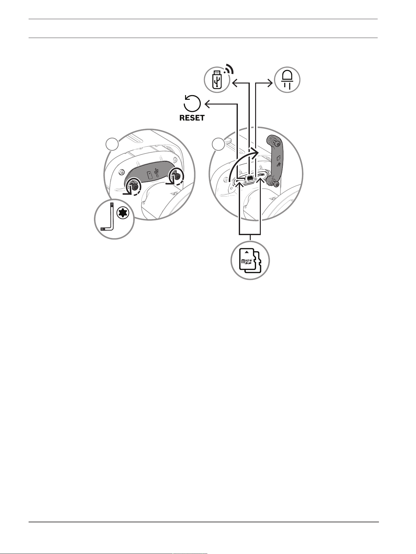
56 en | Troubleshooting DINION 7100i IR
2023-06 | V02 | F.01U.390.686
User manual
Bosch Security Systems B.V.
Access to RESET button
2
1
TR20
1
2
DINION 7100i IR Appendices | en 57
Bosch Security Systems B.V.
User manual
2023-06 | V02 | F.01U.390.686
6 Appendices
6.1 Copyright notices
The firmware uses the fonts "Adobe-Helvetica-Bold-R-Normal--24-240-75-75-P-138-ISO10646-1"
and "Adobe-Helvetica-Bold-R-Normal--12-120-75-75-P-70-ISO10646-1" under the following
copyright:
Copyright 1984-1989, 1994 Adobe Systems Incorporated.
Copyright 1988, 1994 Digital Equipment Corporation.
Permission to use, copy, modify, distribute and sell this software and its documentation for
any purpose and without fee is hereby granted, provided that the above copyright notices
appear in all copies and that both those copyright notices and this permission notice appear
in supporting documentation, and that the names of Adobe Systems and Digital Equipment
Corporation not be used in advertising or publicity pertaining to distribution of the software
without specific, written prior permission.
This software is based in part on the work of the Independent JPEG Group.
Stratocast is a trademark of Genetec, Inc.
6.2 More information
Support
Access our support services at www.boschsecurity.com/xc/en/support/
.
Bosch Security and Safety Systems offers support in these areas:
– Apps & Tools
– Building Information Modeling
– Warranty
– Troubleshooting
– Repair & Exchange
– Product Security
Bosch Building Technologies Academy
Visit the Bosch Building Technologies Academy website and have access to training courses,
video tutorials and documents: www.boschsecurity.com/xc/en/support/training/

58 | Appendices DINION 7100i IR
2023-06 | V02 | F.01U.390.686
User manual
Bosch Security Systems B.V.


Bosch Security Systems B.V.
Torenallee 49
5617 BA Eindhoven
Netherlands
www.boschsecurity.com
© Bosch Security Systems B.V., 2023
202306121210
Building solutions for a better life.