

DINION 3100i IR Table of contents | en 3
Bosch Security Systems B.V.
User manual
2024-02 | V01 | DOC
Table of contents
1
Safety and security information 5
1.1 Safety message explanation 5
1.2 Safety precautions 5
1.3 Important safety instructions 5
1.4 Notices 6
2
Browser connection 10
2.1 System requirements 10
2.2 Establishing the connection 10
2.3 Password protection in camera 10
3
System overview 12
3.1 Live 12
3.2 Playback 12
3.3 Configuration 12
3.4 Dashboard 13
4
Operation via the browser 14
4.1 Live page 14
4.2 Playback page 15
4.2.1 Selecting the recording stream 15
4.2.2 Searching for recorded video 16
4.2.3 Exporting recorded video 16
4.2.4 Track list 16
4.2.5 Controlling playback 16
4.3 Dashboard 16
5
Configuration 18
5.1 General 18
5.1.1 Identification 18
5.1.2 User Management 18
5.1.3 Date/Time 19
5.2 Web Interface 20
5.2.1 Appearance 20
5.2.2 'Live' functions 22
5.3 Connectivity 22
5.3.1 Cloud services 22
5.3.2 Accounts 22
5.3.3 DynDNS 23
5.4 Camera 23
5.4.1 Installer Menu 23
5.4.2 Display Stamping 25
5.4.3 Positioning 27
5.4.4 Color 30
5.4.5 ALC 31
5.4.6 Illuminator 32
5.4.7 Enhance 32
5.4.8 Encoder Streams 33
5.4.9 Encoder Statistics 34
5.4.10 Privacy Masks 35
5.4.11 Pixel Counter 35
5.5 Recording 35

4 en | Table of contents DINION 3100i IR
2024-02 | V01 | DOC
User manual
Bosch Security Systems B.V.
5.5.1 Storage Management 36
5.5.2 Recording Profiles 37
5.5.3 Maximum Retention Time 39
5.5.4 Recording Scheduler 39
5.5.5 Recording Status 40
5.5.6 Recording Statistics 40
5.5.7 Image Posting 40
5.5.8 SD Card Status 41
5.6 Alarm 41
5.6.1 Alarm Connections 41
5.6.2 Video Content Analysis (VCA) 43
5.6.3 Alarm Email 43
5.6.4 Alarm Task Editor 44
5.7 Network 44
5.7.1 Network Services 44
5.7.2 Network Access 44
5.7.3 Advanced 46
5.7.4 Network Management 47
5.7.5 Multicast 48
5.7.6 IPv4 Filter 49
5.8 Service 50
5.8.1 Maintenance 50
5.8.2 Licenses 51
5.8.3 Certificates 51
5.8.4 Logging 51
5.8.5 System Overview 52
6
Troubleshooting 53
6.1 Physical reset button 53
7
Appendices 54
7.1 Copyright notices 54
7.2 More information 54
DINION 3100i IR Safety and security information | en 5
Bosch Security Systems B.V.
User manual
2024-02 | V01 | DOC
1 Safety and security information
Read, follow, and retain for future reference all of the following safety instructions. Follow
all warnings before operating the device.
1.1 Safety message explanation
In this manual, the following symbols and notations are used to draw attention to special
situations:
Danger!
Indicates a hazardous situation which, if not avoided, will result in death or serious injury.
!
Warning!
Indicates a hazardous situation which, if not avoided, could result in death or serious injury.
!
Caution!
Indicates a hazardous situation which, if not avoided, could result in minor or moderate
injury.
i
Notice!
Indicates a situation which, if not avoided, could result in damage to the equipment or
environment, or data loss.
1.2 Safety precautions
!
Caution!
Installation should only be performed by qualified service personnel in accordance with the
National Electrical Code (NEC800 CECSection60) or applicable local codes.
!
Caution!
The product must be supplied only by an external source having an output complying with
PS2 or Annex Q conform to IEC 62368-1 and UL62368-1.
1.3 Important safety instructions
– To clean the device, do not use liquid cleaners or aerosol cleaners.
– Do not install the device near any heat sources such as radiators, heaters, stoves, or
other equipment (including amplifiers) that produce heat.
– Do not spill liquids on the device before installation is completed.
– Take precautions to protect the device from power and lightning surges.
– Adjust only those controls specified in the operating instructions.
– Operate the device only from the type of power source indicated on the label.
– Unless qualified, do not attempt to service a damaged device yourself. Refer all
servicing to qualified service personnel.
6 en | Safety and security information DINION 3100i IR
2024-02 | V01 | DOC
User manual
Bosch Security Systems B.V.
– Install in accordance with the manufacturer's instructions in accordance with
applicable local codes.
– Use only attachments/accessories specified by the manufacturer.
– Protect all connection cables from possible damage, particularly at connection points.
– If using a Class I adapter, the power cord shall be connected to a socket-outlet with
earthing connection.
– The Low Voltage power supply unit used must comply with EN-62368-1.
– These products are intended to be supplied by a Listed Power Adapter marked “L.P.S.”
or “Limited Power Source”, rated 48Vdc, 0.08 A minimum, Tma=40ºC minimum (For
indoor), Tma=50ºC minimum (For outdoor).
i
Notice!
This is a class A product. In a domestic environment this product may cause radio
interference, in which case the user may be required to take adequate measures.
i
Notice!
This equipment has been tested and found to comply with the limits for a Class A digital
device, pursuant to EN 55032. These limits are designed to provide reasonable protection
against harmful interference when the equipment is operated in a commercial environment.
This equipment generates, uses, and can radiate radio frequency energy and, if not installed
and used in accordance with the instruction manual, may cause harmful interference to
radio communications. Operation of this equipment in a residential area is likely to cause
harmful interference in which case the user will be required to correct the interference at
his own expense.
1.4 Notices
i
Notice!
Optical elements are sensitive and should be protected at all times. Do not allow objects to
come into contact with glass surfaces and do not touch optical elements with your fingers.
i
Notice!
Video loss is inherent to digital video recording; therefore, Bosch Security Systems cannot
be held liable for any damage that results from missing video information.
To minimize the risk of losing information, we recommend multiple, redundant recording
systems, and a procedure to back up all analog and digital information.
i
Notice!
This device is intended for use in public areas only.
U.S. federal law strictly prohibits surreptitious recording of oral communications.
UL Disclaimer
Underwriter Laboratories Inc. ("UL") has not tested the performance or reliability of the
security or signaling aspects of this product. UL has only tested fire, shock and/or casualty
hazards as outlined in Standard(s) for Safety for Information Technology Equipment, UL
62368-1. UL Certification does not cover the performance or reliability of the security or
signaling aspects of this product.

DINION 3100i IR Safety and security information | en 7
Bosch Security Systems B.V.
User manual
2024-02 | V01 | DOC
UL MAKES NO REPRESENTATIONS, WARRANTIES, OR CERTIFICATIONS WHATSOEVER
REGARDING THE PERFORMANCE OR RELIABILITY OF ANY SECURITY OR SIGNALING-
RELATED FUNCTIONS OF THIS PRODUCT.
FCC suppliers Declaration of Conformity
DINION 3100i IR: NBE-3702-AL, NBE-3703-AL, NBE-3702-AL-GOV, NBE-3703-AL-GOV
Compliance statement
This device complies with part 15 of the FCC Rules. Operation is subject to the following
two conditions: (1) This device may not cause harmful interference, and (2) this device must
accept any interference received, including interference that may cause undesired
operation.
Responsible party
Bosch Security Systems Inc
130 Perinton Parkway
14450 Fairport, NY, USA
For more information please contact the nearest Bosch Security Systems location or visit:
www.boschsecurity.us
Changes or modifications not expressly approved by the party responsible for compliance
could void the user's authority to operate the equipment.
Note: This equipment has been tested and found to comply with the limits for a Class A
digital device, pursuant to part 15 of the FCC Rules. These limits are designed to provide
reasonable protection against harmful interference when the equipment is operated in a
commercial environment. This equipment generates, uses, and can radiate radio frequency
energy and, if not installed and used in accordance with the instruction manual, may cause
harmful interference to radio communications. Operation of this equipment in a residential
area is likely to cause harmful interference in which case the user will be required to correct
the interference at his own expense.
For use in China: CHINA ROHS DISCLOSURE TABLE
Fixed cameras with lens
Hazardous substance table according to SJ/T 11364-2014
Pb
(Pb)
Hg
(Hg)
Cd
(Cd)
Cr 6+
(Cr 6+)
PBB
(PBB)
PBDE
(PBDE)
Housing & enclosures X O O O O O
PCBA with connectors X O X O O O
Cable assemblies O O O O O O
Image sensor assembly X O X O O O
Lens assembly X O X O O O
This table was created according to the provisions of SJ/T 11364
O: The content of such hazardous substance in all homogeneous materials of such
component is below the limit defined in GB/T 26572
X: The content of such hazardous substance in a certain homogeneous material is above
the limit defined in GB/T 26572

8 en | Safety and security information DINION 3100i IR
2024-02 | V01 | DOC
User manual
Bosch Security Systems B.V.
The manufacturing datecodes of the products are explained in:
http://www.boschsecurity.com/datecodes
IC statement (Canada)
This device complies with Industry Canada licence-exempt RSS standard(s). Operation is
subject to the following two conditions: (1) this device may not cause harmful interference,
and (2) this device must accept any interference received, including interference that may
cause undesired operation.
Le présent appareil est conforme aux CNR d'Industrie Canada applicables aux appareils
radio exempts de licence. L'exploitation est autorisée aux deux conditions suivantes:
(1) l'appareil ne doit pas produire de brouillage, et
(2) l'utilisateur de l'appareil doit accepter tout brouillage radioélectrique subi, même si le
brouillage est susceptible d'en compromettre le fonctionnement.
VCCI statement (Japan)
This is a ClassB device in accordance with the VCCI Council standard. Using this device
near a radio or television receiver in a domestic environment may cause radio interference.
Install and use this device according to the documented recommendations.
CMIM statement (Morocco)
This device falls under the scope and is compliant with the Moroccan LVD/EMC Directive,
establishing: (1) technical regulations for electrical equipment designed to be used with a
nominal tension between 50-1000VAC and 75-1500VDC; (2) specific technical regulations
for electromagnetic compatibility of equipment, excluding wireless and telecommunications
terminals and other types of devices.
RCM statement (Australia and New Zealand)
This device falls under the scope and is compliant with the Australian Communications
Media Authority (ACMA) scheme and the Electrical Equipment Safety System (EESS)
scheme, as defined by the Electrical Regulatory Authorities Council (ERAC) of Australia,
establishing that the device is suitable for household, personal or similar use with a voltage
greater than 50VAC RMS or 120V ripple-freeDC, and less than 1000VAC RMS or 1500V
ripple-free DC. It is immaterial whether the low voltage electrical and electronic equipment
is also designed or marketed to be used for commercial or industrial purposes.
Use latest software
Before operating the device for the first time, make sure that you install the latest
applicable release of your software version. For consistent functionality, compatibility,
performance, and security, regularly update the software throughout the operational life of
the device. Follow the instructions in the product documentation regarding software
updates.
The following links provide more information:
– General information: https://www.boschsecurity.com/xc/en/support/product-security/
– Security advisories, that is a list of identified vulnerabilities and proposed solutions:
https://www.boschsecurity.com/xc/en/support/product-security/security-
advisories.html
Bosch assumes no liability whatsoever for any damage caused by operating its products
with outdated software components.

DINION 3100i IR Safety and security information | en 9
Bosch Security Systems B.V.
User manual
2024-02 | V01 | DOC
Old electrical and electronic equipment
This product and/or battery must be disposed of separately from household waste.
Dispose such equipment according to local laws and regulations, to allow their
reuse and/or recycling. This will help in conserving resources, and in protecting
human health and the environment.

10 en | Browser connection DINION 3100i IR
2024-02 | V01 | DOC
User manual
Bosch Security Systems B.V.
2 Browser connection
A computer with a web browser (Google Chrome, Microsoft Edge, or Mozilla Firefox) is used
to receive live images, control the unit, and replay stored sequences. The unit is configured
over the network using the browser.
2.1 System requirements
Our recommendations are:
– Computer with Dual core HyperThreading processor or better
– Graphic card with performance that matches or is better than the resolution of the
camera
– Windows10 or later
– Network access
– Google Chrome, Microsoft Edge, or Mozilla Firefox
- or -
Application software, for example, VideoSecurityClient, BoschVideoClient or BVMS.
Note:
To see live images in your browser it might be necessary to download and install the MPEG-
ActiveX from the Bosch download store.
2.2 Establishing the connection
The unit must have a valid IP address and a compatible subnet mask to operate on your
network. By default, DHCP is pre-set at the factory to On and so your DHCP server assigns
an IP address. With no DHCP server the default address is automatically assigned via link-
local address.
The Project Assistant app or Configuration Manager can be used to find the IP address.
Download the software from https://downloadstore.boschsecurity.com
:
1. Start the web browser.
2. Enter the IP address of the device as the URL.
3. During the initial installation, confirm any security questions that show.
If a RADIUS server is used for network access control (802.1x authentication), you must
configure the device before the device can communicate with the network.
To configure the device, connect it directly to a computer using a network cable and then
set the service-level password.
Note:
If you cannot connect, the unit may have reached its maximum number of connections.
Depending on the device and network configuration, each unit can have up to 50 web
browser connections, or up to 100 connections via BoschVideoClient or BVMS.
2.3 Password protection in camera
The device is password-protected. The first time that any user accesses the device, the
device will prompt the user to set a password at the service level.
The camera requires a strong password. Follow the prompts in the dialog box, which
specifies what is required. The system measures the strength of the password that you
enter.
Make sure the password obeys these conditions:
– 8 to 19 characters in length
– Upper and lower case letters
– Minimum of 1 digit

DINION 3100i IR Browser connection | en 11
Bosch Security Systems B.V.
User manual
2024-02 | V01 | DOC
– Minimum of 1 special character
These special characters are not allowed: '@', '&', '<', '>', ':', '+'
When you use Configuration Manager to access your device for the first time, you must set
the initial password of the device in Configuration Manager. The Users section (General >
Unit Access > Users) displays the message, "Before you can use this device you have to
secure it with an initial password."
Note: After you set the initial password, a "lock" icon appears next to the device name in the
Devices list in Configuration Manager.
You can also launch the device webpage directly. In the device webpage, an initial password
page appears, displaying input fields and a password strength gauge.
Enter the user name (“service”) and a password in the appropriate fields. Refer to the
section User Management for more information.
After a service-level password is set for the device, the device displays a dialog box that
prompts users to enter the user name (“service”) and the service-level password every time
that they access the device.
1. Fill in the fields User name and Password.
2. Click OK. If the password is correct, the desired page appears.
Note: New releases of software may require you to set a new and stronger password.
12 en | System overview DINION 3100i IR
2024-02 | V01 | DOC
User manual
Bosch Security Systems B.V.
3 System overview
Note: None of the pages are accessible until after you set a service-level password.
When a connection is established, the Live page is initially displayed.
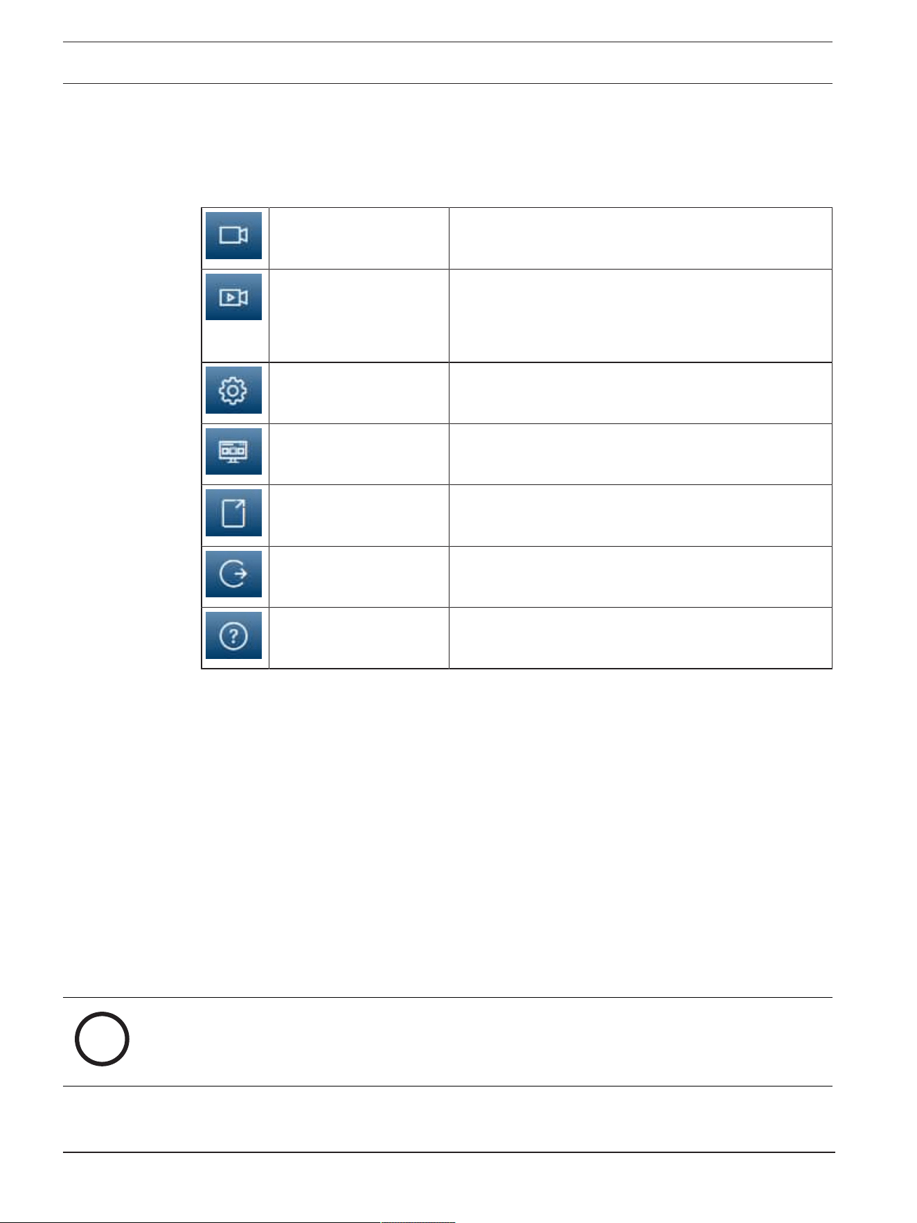
The application bar displays the following icons:
Live Click this icon to view the live video stream.
Playback Click this icon to play back recorded sequences.
This link is only visible if a storage medium has been
configured for recording. (With VRM recording, this
option is not active.)
Configuration Click this icon to configure the device.
Dashboard Click this icon to see detailed system information.
Links Click this icon to navigate to the Bosch download
store.
Logout Click this icon to log out of the device.
Click this icon to get context-sensitive help for the
page you are browsing.
3.1 Live
The Live page is used to display the live video stream and control the unit.
3.2 Playback
The Playback page is used for playing back recorded sequences.
3.3 Configuration
The Configuration page is used to configure the unit and the application interface.
Making Changes
Each configuration screen shows the current settings. You can change the settings by
entering new values or by selecting a predefined value from a list field.
Not every page has a Set button. Changes to pages without a Set button are set
immediately. If a page does show a Set button, you must click the Set button for a change
to take effect.
i
Notice!
Save each change with the associated Set button.
Clicking the Set button saves the settings only in the current field. Changes in any other
fields are ignored.
Some changes only take effect after the unit is rebooted. In this case, the Set button
changes to Set and Reboot.

DINION 3100i IR System overview | en 13
Bosch Security Systems B.V.
User manual
2024-02 | V01 | DOC
1. Make the desired changes.
2. Click the Set and Reboot button. The camera reboots and the changed settings are
activated.
3.4 Dashboard
The Dashboard page is used to display detailed information about the device.
The Dashboard is only visible in the application bar if the Show 'Dashboard' option is
enabled by a service-level user in the Configuration -> Web Interface -> Appearance page.
14 en | Operation via the browser DINION 3100i IR
2024-02 | V01 | DOC
User manual
Bosch Security Systems B.V.
4 Operation via the browser
4.1 Live page
After the connection is established, the Live page is initially displayed. It shows the live
video image on the right of the browser window. Depending on the configuration, various
text overlays may be visible on the live video image.
Other information may also be shown next to the live video image. The items shown depend
on the settings on the 'Live' functions page.
Connection
In the Connection group, you can configure the Stream option.
Video stream selection
To view a live stream of the selected video channel:
1. On the left side of the browser, expand the Connection group if necessary.
2. Click the Stream drop-down arrow to see the options.
Select the stream you wish to view.
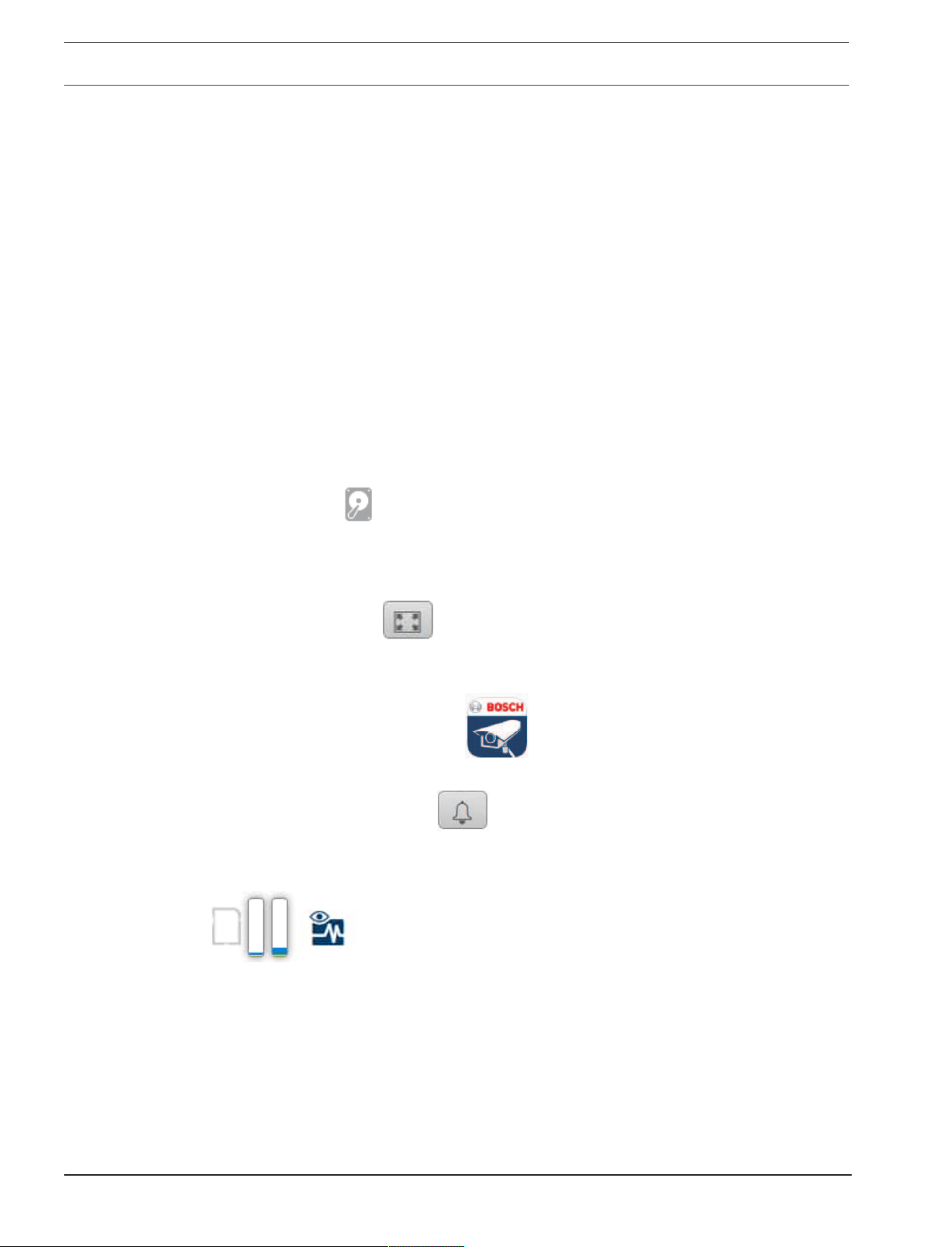
Recording status
The hard drive icon
below the live camera image changes during an automatic
recording. The icon lights up and displays a moving graphic to indicate a running recording.
If no recording is taking place, a static icon is displayed.
Full-screen display
Click the full-screen icon
to view the selected stream in full-screen mode; press Esc
on the keyboard to return to the normal viewing window.
Start Video Security app
To start the Video Security app, click
.
Show latest event
Click the Show latest event icon
to watch the last recorded important events.
The Playback page opens.
Storage, CPU and network status
When accessing the unit with a browser, the local storage, processor and network status
icons are shown in the upper right of the window.
When a local storage card is available, the memory card icon changes color (green, orange
or red) to indicate the local storage activity. If you hover over this icon with the mouse the
storage activity is shown as a percentage.
If you hover over the middle icon, the CPU load is shown.
If you hover over the right-hand icon, the network load is shown.
This information can help with problem solving or when fine tuning the unit. For example:
– if the storage activity is too high, change the recording profile,
DINION 3100i IR Operation via the browser | en 15
Bosch Security Systems B.V.
User manual
2024-02 | V01 | DOC
– if the CPU load is too high, change the VCA settings,
– if the network load is too big, change the encoder profile to reduce bitrate.
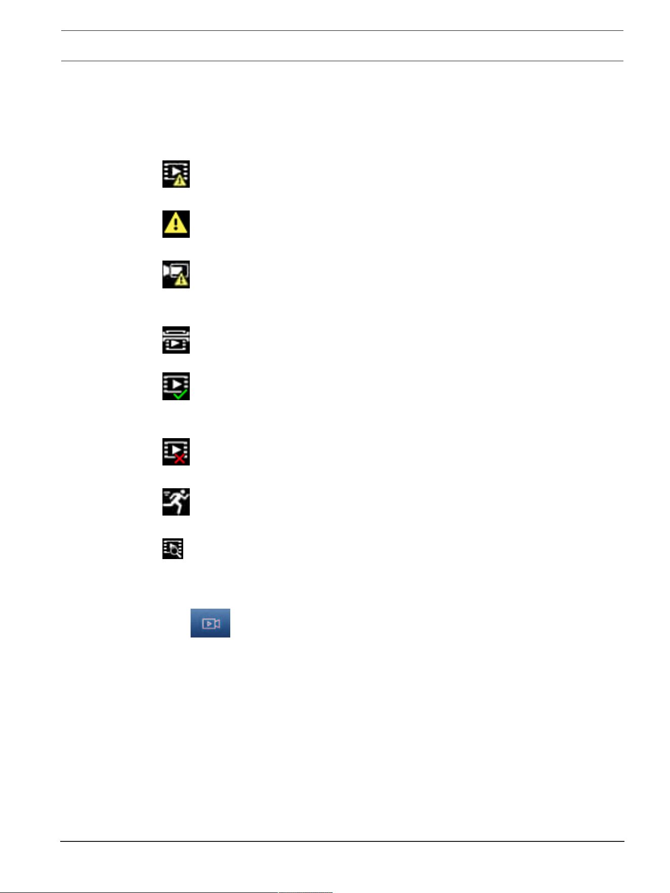
Status icons
Various overlays in the video image provide important status information. The overlays
provide the following information:
Decoding error
The frame might show artifacts due to decoding errors.
Alarm flag
Indicates that an alarm has occurred.
Communication error
A communication error, such as a connection failure to the storage medium, a protocol
violation or a timeout, is indicated by this icon.
Gap
Indicates a gap in the recorded video.
Watermark valid
The watermark set on the media item is valid. The color of the check mark changes
according to the video authentication method that has been selected.
Watermark invalid
Indicates that the watermark is not valid.
Motion alarm
Indicates that a motion alarm has occurred.
Storage discovery
Indicates that recorded video is being retrieved.
4.2 Playback page
Click
Playback in the application bar to view, search or export recordings. This link
is only visible when a direct iSCSI or memory card is configured for recording (with Video
Recording Manager (VRM) recording this option is not active).
On the left side of the screen, there are four groups:
– Connection
– Search
– Export
– Track list
4.2.1 Selecting the recording stream
Expand the Connection group on the left side of the browser.
To view a recording stream:
– Click the Recording drop-down arrow to see the options.
– Select one of the numbered recording streams.

16 en | Operation via the browser DINION 3100i IR
2024-02 | V01 | DOC
User manual
Bosch Security Systems B.V.
4.2.2 Searching for recorded video
Expand the Search group on the left side of the browser.
– To limit the search to a particular time range, enter the date and times for the start and
stop points.
– Select an option from the drop-down box to define a search parameter.
– Click Search.
– The results are listed in a new window. Click a result to play it back.
– Click Back to define a new search.
– Click Last results to display the latest search results.
4.2.3 Exporting recorded video
On the left side of the browser, expand the Export group if necessary:
1. Select a track in the track list or in the search results.
2. The start and stop date and time are filled for the selected track. If necessary, change
the times.
3. In the Time lapse drop-down box, select Original, to export the recorded video as its
original, Condensed to export the recorded video condensed to the given output time.
4. In the Location drop-down box, select a target.
5. Click Export to save the video track.
Note:
The target server address is set on the Connectivity>Accounts page.
4.2.4 Track list
The Track list shows all the available recordings.
4.2.5 Controlling playback
The time bar below the video image allows quick orientation. The time interval associated
with the sequence is displayed in the bar in gray. Arrows indicate the position of the image
currently being played back within the sequence.
The time bar offers various options for navigation in and between sequences.
– If required, click in the bar at the point in time at which the playback should begin.
– Change the time interval displayed by clicking the plus or minus icons or use the mouse
scroll wheel. The display can span a range from six months to one minute.
– Click the alarm jump buttons to go from one alarm event to the next or to the previous
one. Red bars indicate the points in time where alarms were triggered.
Controls
Control playback by means of the buttons below the video image.
The buttons have the following functions:
– Start/Pause playback
– Select the playback (forward or backward) speed using the speed regulator
– Step forward or backward frame-by-frame when paused (small arrows)
4.3 Dashboard
The Dashboard page shows information on 4 topics:
– Device status
– Recording status
– Connection Status
– Services
You can also download a .JSON file with information about the device:

DINION 3100i IR Operation via the browser | en 17
Bosch Security Systems B.V.
User manual
2024-02 | V01 | DOC
1. At the bottom of the page, locate the Export button
2. Click the Export button
3. Select a location in your hard drive to store the file

18 en | Configuration DINION 3100i IR
2024-02 | V01 | DOC
User manual
Bosch Security Systems B.V.
5 Configuration
5.1 General
5.1.1 Identification
Device name
Assign a unique name to assist in identification. This name simplifies the management of
multiple devices in more extensive systems.
The name is used for remote identification, for example, in the event of an alarm. Choose a
name that makes it as easy as possible to identify the location unambiguously.
Device ID
Each device should be assigned a unique identifier that can be entered here as an additional
means of identification.
Video name
Each video channel can be given a name. Click the + sign to add an extra line.
Host name
Enter the host name registered for the device.
Initiator extension
Add text to an initiator name to make identification easier in large iSCSI systems. This text is
added to the initiator name, separated from it by a full stop. (You can see the initiator name
in the System Overview page.)
Click Set to apply the changes.
5.1.2 User Management
A password prevents unauthorized access to the device. You can use different authorization
levels to limit access.
Proper password protection is only guaranteed when all higher authorization levels are also
protected with a password. Therefore, you must always start from the highest authorization
level when assigning passwords.
You can define and change a password for each authorization level if you are logged into the
“service” user account.
Authentication modes
The section Authentication modes provides information about the authentication modes set
in the camera. A checkmark appears in the checkbox to the left of the mode if the mode is
set. If the mode is not set, the phrase “No certificate installed” appears to the right of the
mode name.
This device has three authentication modes:
– Password indicates a password is set for the camera. It prevents unauthorized access
to the device, and can use different authorization levels to limit access.
Proper password protection is only guaranteed when all higher authorization levels are
also protected with a password. Therefore, you must always start from the highest
authorization level when assigning passwords.
You can define and change a password for each authorization level if you are logged
into the service user account.
– Certificate. A check mark in this check box indicates that at least one certificate is
loaded onto the device.
The Trusted certificate is a root certificate for Bosch Security Systems that proves that
the device meets the following criteria:
– It originates from a Bosch factory that is a secure environment.

DINION 3100i IR Configuration | en 19
Bosch Security Systems B.V.
User manual
2024-02 | V01 | DOC
– It has not been tampered with.
The Trusted certificate is issued by Escrypt. Escrypt is a Bosch company and Certificate
Authority (CA).
– Active Directory server (AD FS). A check mark in this check box indicates that the
device uses an active directory server.
Click Set to apply the changes.
Creating a new user
To create a new user, click Add in the section below Authentication modes.
In the box User, fill in the fields:
1. User name, Enter a name with a minimum of 5 and a maximum of 31 characters.
2. Group, select the appropriate authorization level:
– live is the lowest authorization level. At this level, it is only possible to view the
live video image, and switch between the different live image displays.
– user is a middle authorization level. At this level, it is possible to operate the
device and playback recordings, but configuration changes are not possible.
– IVA configuration is a middle authorization level. At this level, it is only possible to
configure VCA, but access is available to all user level functions like PTZ and
Replay.
– service is the highest authorization level. Entering the correct password gives
access to all the functions, and allows all configuration settings to be changed.
3. Type, select either:
– Password for a new password.
Use a minimum of 8 and a maximum of 19 characters. The password must have
upper-case and lower-case letters, one or more numerical digits and one or more
of these special characters ! ? ” # $ % ( ) { } [ ] * - = . , ; ^ _ | ~ \
Special characters such as space @ : < > ‘ & + are not valid.
In this case, enter the new password a second time to eliminate typing mistakes.
– Certificate for a certificate that the new user is authorized to use.
4. Click Set to confirm and create a new user.
To edit a password
To edit a password, click the pencil icon to the right of the column Type for the appropriate
User name.
5.1.3 Date/Time
Date format
Select the required date format from the dropdown menu.
Device date/Device time
i
Notice!
Make sure that recording is stopped before synching to the PC.
If there are multiple devices operating in your system or network, it is important to
synchronize their internal clocks. For example, it is only possible to identify and correctly
evaluate simultaneous recordings when all units are operating on the same time.
1. Enter the current date. Since the unit time is controlled by the internal clock, there is
no need to enter the day of the week - it is added automatically.
2. Enter the current time or click the Sync to PC button to copy your computer's system
time to the camera.

20 en | Configuration DINION 3100i IR
2024-02 | V01 | DOC
User manual
Bosch Security Systems B.V.
Note: It is important that the date/time is correct for recording. An incorrect date/time
setting could prevent correct recording.
Device time zone
Select the time zone in which the system is located.
Daylight saving time
The internal clock can switch automatically between normal and daylight saving time (DST).
The unit already contains the data for DST switch-overs for many years in advance. If the
date, time and zone have been set up correctly, a DST table is automatically created.
If you decide to create alternative daylight saving time dates by editing the table, note that
values occur in linked pairs (DST start and end dates).
First, check the time zone setting. If it is not correct, select the appropriate time zone and
click Set.
1. Click Details to edit the DST table.
2. Click Generate to fill the table with the preset values from the unit.
3. Click one of the entries in the table to make changes. The entry is highlighted.
4. Click Delete to remove the entry from the table.
5. Choose other values from the list boxes under the table, to change the selected entry.
Changes are immediate.
6. If there are empty lines at the bottom of the table, for example after deletions, add new
data by marking the row and selecting values from the list boxes.
7. When finished, click OK to save and activate the table.
Time server address
The camera can receive the time signal from time server using various time server protocols,
and then use it to set the internal clock. The unit polls the time signal automatically once
every minute.
Enter the IP address of a time server here.
You can choose to have the DHCP server give a time server date by selecting the Overwrite
by DHCP option.
Time server type
Select the protocol that is supported by the selected time server.
– Select Time protocol if the server uses the protocol RFC868.
– The SNTP protocol supports a high level of accuracy and is required for special
applications and subsequent function extensions.
– Select TLS protocol if the server uses the RFC 5246 protocol.
– Select Off to disable the time server.
Click Set to apply the changes.
5.2 Web Interface
5.2.1 Appearance
You can adapt the appearance of the web interface and change the website language to
meet your requirements.
Website language
Select the language for the user interface.
The default language is English.
After setting the new language, the page refreshes automatically. The GUI now displays field
names and options, as well as OSD messages, in the selected language.

DINION 3100i IR Configuration | en 21
Bosch Security Systems B.V.
User manual
2024-02 | V01 | DOC
Show VCA metadata
When video content analysis (VCA) is activated, additional information is displayed in the
live video stream. With the MOTION+ analysis type, for example, the sensor fields in which
motion is recorded are marked with yellow rectangles.
Using video analytics the outlines of detected objects are displayed in following colors:
– Red: Objects that generate an alarm event under the current settings appear on the
camera image inside a red outline.
– Orange: An object that has triggered one alarm event but does not generate another
appears inside an orange outline (example: object has crossed a line). During forensic
search, an object that triggers an alarm event has an orange outline from the beginning.
– Yellow: Objects that are detected as moving but do not generate an alarm event under
the current settings appear inside a yellow outline.
Show VCA trajectories
When this option is activated, the trajectories (motion lines of objects) from the video
content analysis are displayed in the live video image if a corresponding analysis type is
activated. The trajectory is shown as a green line following the object base point.
Show overlay icons
Select this check box to show overlay icons on the live video image.
Show 'Dashboard'
Select this checkbox to enable the Dashboard in the application bar.
Secure cookies
Select this checkbox to secure the cookies sent through the camera.
i
Notice!
If cookies are secured, authentication forwarding to MPEG ActiveX and the Video Security
App is prohibited.
HTTP referrer check
Click this option to disable HTTP referrer checking. This option is enabled by default.
The HTTP referrer check works as a protection against a CSRF (Cross-site request forgery)
attack.
If a use case requires not sending the HTTP referrer, you can disable this option. In this
situation, you might require other mitigations against CSRF attacks.
Video player
Select the type of player to be used for live mode viewing.
Video buffer
The value shown is calculated from the Latency mode setting. It cannot be changed.
JPEG resolution
Specify the size of the JPEG image on the Live page from the dropdown list.
Resource based is activated by default.
Note: Resource based will apply the best resolution possible based on the available
resources.
JPEG interval
You can specify the interval at which the individual images should be generated for the M-
JPEG image on the Live page.
Enter a time interval (in milliseconds). The default is 0.

22 en | Configuration DINION 3100i IR
2024-02 | V01 | DOC
User manual
Bosch Security Systems B.V.
JPEG quality
You can specify the quality at which the JPEG images appear on the Live page.
This option is only available if JPEG resolution is not set to Resource based.
Login page text
Type the text you want to display to a user in the Login page before he accesses the device
with the respective User name and Password.
Click Set to apply the changes.
5.2.2 'Live' functions
Auto logout time [min]
Set a time frame (in minutes) for the automatic logout. Default value is 0 (no automatic
logout).
Click Set to apply the changes.
5.3 Connectivity
5.3.1 Cloud services
Remote Portal
Operation
The operation mode determines how the camera communicates with the Remote Portal.
– Select On to poll the server constantly.
– Select Off to block polling.
– Select Re-register to different account if you want to register the camera to another
Remote Portal account.
Connectivity state
This field indicates the device's connectivity state with Remote Portal.
– If the device is registered and the operation mode is set to On, the state will indicate
that the device is Connected (to the cloud service).
Note: The Visit Remote Portal button will become active.
– If the device is not registered or the operation mode is set to Off, the state will indicate
that the device is Not available.
Note: The Register button will become active only if you have not registered the device to
the Remote Portal.
Partner services
Stratocast
Enter the Stratocast Registration code to connect with the Genetec’s Stratocast cloud.
Click Register to activate the account.
5.3.2 Accounts
Four separate accounts can be defined for posting and recording export.
Type
Select the account type.
Account name
Enter an account name to be shown as the target name.
IP address
Enter the IP address for an FTP server.

DINION 3100i IR Configuration | en 23
Bosch Security Systems B.V.
User manual
2024-02 | V01 | DOC
Login
Enter your login name for the account server.
Password
Enter the password that gives access to the account server. Click Check to confirm that it is
correct.
Path
Enter an exact path to post the images on the account server. Click Browse... to browse to
the required path.
Maximum bit rate
Enter the maximum bit rate in kbps that will be allowed when communicating with the
account.
Encryption
Tick the box to use a secure FTP over TLS connection.
Click Set to apply the changes.
5.3.3 DynDNS
A dynamic Domain Name Service (DNS) allows you to select the unit via the Internet using a
host name, without having to know the current IP address of the unit. You can enable this
service here. To do this, you must have an account with one of the dynamic DNS providers
and you must register the required host name for the unit on that site.
Note:
For information about the service, registration process and available host names refer to the
provider.
Enable DynDNS
Use the drop-down menu to select On or Off to enable or disable DynDNS.
Provider
Select your dynamic DNS Provider from the drop-down list.
Host name
Enter the host name registered for the unit.
User name
Enter the user name you registered.
Password
Enter the password you registered.
Force registration now
Force the registration by transferring the IP address to the DynDNS server. Entries that
change frequently are not provided in the Domain Name System. It is a good idea to force
the registration when setting up the device for the first time. Only use this function when
necessary and no more than once a day, to avoid the possibility of being blocked by the
service provider. To transfer the IP address of the device, click the Register button.
Status
The status of the DynDNS function is displayed here for information purposes; these
settings cannot be changed.
Click Set to apply the changes.
5.4 Camera
5.4.1 Installer Menu

24 en | Configuration DINION 3100i IR
2024-02 | V01 | DOC
User manual
Bosch Security Systems B.V.
Sensor mode
The sensor mode specifies the base resolution and frame rates for the image quality
settings. Fast moving scenes use more frame rates for better image quality than slow moving
scenes. Adjust this setting as necessary.
Some types of light can show flickering in the image when the frame rate is not
synchronized with the mains power frequency.
Make sure the selected sensor mode frame rate is in line with the mains power frequency:
– 50Hz: 25fps
– 60Hz: 30fps
Image rotation
This device has four image rotation options:
– 0°
– 90° - upright
– 180°
– 270° - upright
Select the option that best suits the device mounting position.
The upright modes (90° and 270°) are good for vertical scenes, such as hallways or
perimeters. When these options are selected, the aspect ratio and the signaling to the
interfaces change (example, 16:9 to 9:16).
If the device is mounted in its normal position, select 0°.
The end result is shown in the Live preview.
Mirror image
Select On to output a mirror image of the device picture.
The end result is shown in the Live preview.
Lens Wizard
The camera view is configured with the Lens Wizard.
You can use the wizard to configure the field of view and focus of the lens.
– Live Video window
– The Live Video window shows a live video stream. Click in the live video window to
move the device and center its field of view at the selected position. The device
also automatically levels the horizon.
– On some browsers, such as Firefox and Chrome, a rectangle can be drawn on the
live video window. The device automatically centers the field of view at the
selected position, levels the horizon and also zooms in.
– Set lens to default position
– Select Default to set the lens to its default position.
– Optical zoom
– Use the slider to adjust the optical zoom.
– Autofocus
– Select either Local Range (preferred selection) or Full Range (backup selection)
to automatically focus the image.
– Focus position
– Use the slider to adjust the focus position. The focus position automatically adjusts
to the autofocus.
– Focus indicator
– The Focus indicator shows a value related to the focus quality of the image. The
higher the value, the more in focus the image will be.
– Lens
– Indicates the lens type in use.

DINION 3100i IR Configuration | en 25
Bosch Security Systems B.V.
User manual
2024-02 | V01 | DOC
– IR-corrected lens
– Click the checkbox to activate or deactivate IR correction function.
The setting of the lens mode is crucial to ensure optimal performance. In daylight
operation, the IR-corrected mode is not required. In dark environments where the
majority of light is provided by the IR illuminators, the lens should be set to IR-
corrected mode. Otherwise, if sufficient ambient light is available, disable the IR-
corrected mode. An incorrect lens setting could result in improper focusing.
Camera LED
Click the Enabled or Disabled check-box to switch the Camera LED on or off.
Select Auto disable to let the camera determine when the LED should be switched off.
The camera LED activates when powering on the camera for the first time. The LED
deactivates automatically after 5min.
Reboot device
Click the Reboot button to restart the device. The entire reboot sequence takes
approximately 60seconds.
Restore settings
Click Restore to restore all settings, except network settings, to their defaults.
Note: Clicking this button also clears the service-level password. Operators must reset the
password before doing anything else.
Factory defaults
Click Defaults to restore all settings, including passwords and network settings, to their
defaults.
Note: Clicking this button also clears the service-level password. Operators must reset the
password before doing anything else.
5.4.2 Display Stamping
Various overlays or stamps in the video image provide important supplementary information.
These overlays can be enabled individually and arranged on the image in a clear manner.
The drop-down menus below allow the configuration of the individual stamping options. The
respective sample windows show a preview of the configured text and background styles.
Click Set to apply the changes.
Global configuration
i
Notice!
These options can also be configured individually for all stamping settings.
Any changes to the global configuration settings will be applied to all stamping settings!
– Stamping size
Select the desired font size of the overlays on the OSD: Normal, Large or Custom.
Select Custom to enable the Font size (‰) field.
– Text color
Select the color for the alarm message to be displayed in.
– Background color
Select the background color for the alarm message to be displayed in.
If you have enabled the Transparent background option, the background color is not
displayed in the OSD.

26 en | Configuration DINION 3100i IR
2024-02 | V01 | DOC
User manual
Bosch Security Systems B.V.
Camera name stamping
– Position
Select the position of the camera name overlay in the drop-down box. It can be displayed at
the Top, at the Bottom, or at a position of choice using the Custom option, or it can be set
to Off for no overlay information.
If the Custom option is selected, enter values in the X and Y position fields.
– Stamping size
Select the desired font size of the overlays on the OSD: Normal, Large or Custom.
Select Custom to enable the Font size (‰) field.
– Text color
Select the color for the alarm message to be displayed in.
– Background color
Select the background color for the alarm message to be displayed in.
If you have enabled the Transparent background option, the background color is not
displayed in the OSD.
Optionally, tick the Underlay with full-width bar box to place a full-width background-bar
beneath the time stamp.
i
Notice!
Camera / video names can be changed under General > Identification.
Logo stamping
– Enable
Check this box to enable Logo stamping.
– Position (XY)
This parameter becomes visible if Logo stamping is enabled.
Insert the values for the X and Y coordinates to specify the logo's position.
– Transparent background
Enable this option to hide the logo's background.
– Logo
To place a logo on the image, select and upload an uncompressed .bmp file with a maximum
size of 128x128 pixels and 256 colors to the camera.
Time stamping
– Position
Select the position of the camera name overlay in the drop-down box. It can be displayed at
the Top, at the Bottom, or at a position of choice using the Custom option, or it can be set
to Off for no overlay information.
If the Custom option is selected, enter values in the X and Y position fields.
– Stamping size
Select the desired font size of the overlays on the OSD: Normal, Large or Custom.
Select Custom to enable the Font size (‰) field.
– Text color
Select the color for the alarm message to be displayed in.
– Background color
Select the background color for the alarm message to be displayed in.

DINION 3100i IR Configuration | en 27
Bosch Security Systems B.V.
User manual
2024-02 | V01 | DOC
If you have enabled the Transparent background option, the background color is not
displayed in the OSD.
Alarm mode stamping
– Position
Select the position of the camera name overlay in the drop-down box. It can be displayed at
the Top, at the Bottom, or at a position of choice using the Custom option, or it can be set
to Off for no overlay information.
If the Custom option is selected, enter values in the X and Y position fields.
– Stamping size
Select the desired font size of the overlays on the OSD: Normal, Large or Custom.
Select Custom to enable the Font size (‰) field.
– Alarm message
Enter the message to be displayed on the image in the event of an alarm. The maximum text
length is 32characters.
– Text color
Select the color for the alarm message to be displayed in.
– Background color
Select the background color for the alarm message to be displayed in.
If you have enabled the Transparent background option, the background color is not
displayed in the OSD.
Stream security
Select from the Video authentication drop-down box a method for verifying the integrity of
the video.
If you select Watermarking, all images are marked with an icon. The icon indicates if the
sequence (live or saved) has been manipulated.
If you want to add a digital signature to the transmitted video images to ensure their
integrity, select one of the cryptographic algorithms for this signature.
Set the Signature interval [s] for the selected authentication method.
Click Set to apply the changes.
5.4.3 Positioning
The Positioning feature describes the location of the camera and the perspective in the
camera’s field of view.
Perspective information is essential to Video Analytics, as it enables the system to
compensate for the illusory smallness of distant objects.
Only through use of perspective information is it possible to distinguish objects such as
persons and cars, and accurately compute their real size as they move through 3D space.
However, to calculate perspective information accurately, the camera must be directed at a
single, flat horizontal plane. Multiple and inclined planes, hills, stairs can falsify perspective
information and produce incorrect object information such as size and speed.
Mounting position
The mounting position describes the perspective information that is also often called
calibration.
In general, the mounting position is determined by the parameters of the camera such as
height, roll angle, tilt angle, and focal length.

28 en | Configuration DINION 3100i IR
2024-02 | V01 | DOC
User manual
Bosch Security Systems B.V.
The height of the camera must always be entered manually. Whenever possible, roll angle
and tilt angle are provided by the camera itself. The focal length is provided, if the camera
has a built-in lens.
Tilt angle [°]
Enter the tilt angle if the value is not determined by the camera.
The tilt angle describes the angle between the horizontal and the camera.
A tilt angle of 0° means that the camera is mounted parallel to the ground.
A tilt angle of 90° means that the camera is mounted vertically in bird’s eye view
perspective.
The flatter the tilt angle is set, the less accurate the estimate of object sizes and speeds will
be. The settings must be between 0° and 90°. Estimates are no longer possible when you
have reached 0°.
Roll angle [°]
Enter the roll angle if the value is not determined by the camera.
The roll angle describes the angle between the roll axis and the horizontal plane. The angle
can deviate from the horizontal by up to 45°.
Height [m]
Enter the height in meters of the position of the camera.
The height describes the vertical distance from the camera to the ground plane of the
captured image. Typically the elevation of the mounted camera above the ground.
Focal length [mm]
Enter the focal length in millimeters of the position of the camera if the value is not
determined by the camera.
The focal length is determined by the lens. The shorter the focal length, the wider the field
of view. The longer the focal length, the narrower the field of view and the higher the
magnification.
Sketch
Click to improve the automatic calibration. The Sketch-based calibration window is
displayed.
The Sketch functionality offers an additional, half-automatic calibration method. This
calibration method allows you to describe the perspective in the camera’s field of view by
drawing vertical lines, ground lines, and ground angles in the camera image and entering the
correct size and angle. Use the Sketch functionality if the result of the automatic calibration
is not sufficient.
You can also combine this manual calibration with the values for roll angle, tilt angle, height
and focal length calculated by the camera or entered manually.
Select the Calculate check box to obtain the roll angle, tilt angle, height and focal length
from the sketched calibration elements - vertical lines, ground lines and angles - you have
placed in the device.
Clear the Calculate check box to enter a value manually or to refresh to the values provided
by the device itself.
Assisted calibration with Configuration Manager
Calibration leverages data from the device's internal sensors and/or direct user input.
With Configuration Manager the device can be calibrated using the map-based calibration
feature, which allows fast and easy calibration by marking ground points on the map and
image.
Alternatively, the user can still resort to the Sketch-based calibration to manually input the
calibration values.
DINION 3100i IR Configuration | en 29
Bosch Security Systems B.V.
User manual
2024-02 | V01 | DOC
Refer to the Configuration Manager Online help content to learn more about assisted
calibration methods.
Calibrating cameras using the Sketch-based calibration window
To determine non-automatically set values:
1. Enter the value for tilt angle, roll angle, height and focal length if the value is known,
for example, by measuring the height of the camera above the ground, or reading the
focal length from the lens.
2. For each value that is still unknown, select the Calculate check box, then place a
calibration element on the camera image. Use these calibration elements to trace
individual outlines of the displayed environment in the camera image and define the
position and size of these lines and angles.
– Click to place a vertical line across the image.
A vertical line corresponds to a line that is perpendicular to the ground plane, such
as a door frame, edge of a building or a lamp post.
– Click to place a line across the ground in the image.
A line on ground corresponds to a line that is on the ground plane, such as a road
marking.
– Click to place an angle on the ground in the image.
The angle on ground represents an angle lying on the horizontal ground plane,
such as the corner of a carpet or parking bay markings.
3. Adjust the calibration elements to the situation:
– Enter the real size of a line or angle. To do this, select the line or angle, then enter
the size in the corresponding box.
Example: You have placed a line on ground across the lower side of an automobile.
You know that the automobile is 4m long. Enter 4m as the length of the line.
– Adjust the position or length of a line or angle. To do this, drag the line or angle or
move the end points to the desired position in the camera image.
– Remove a line or angle. To do this, select the line or angle, then click the trash can
icon.
Note:
Blue lines indicate calibration elements added by you.
White lines represent the element as it should be positioned on the camera image
based on the current calibration results or the determined calibration data.
i
Notice!
If the distance to the camera (geolocation) is not relevant, it is enough to determine height
and focal length in relation to each other. This allows a simple calibration by marking 2-3
persons ‑ each with a vertical line ‑ and setting their size. 1,80m (71 in.) for all is sufficient.
Use at least one person in the front and one person in the background of the image for best
results.
Coordinate system
Select the coordinate system and enter the appropriate values in the additional input fields
that appear depending on the coordinate system selected.
The Coordinate system feature describes the position of the camera in a local Cartesian or
the global WGS 84 coordinate system. The camera and the objects tracked by the video
analytics are displayed on a map.

30 en | Configuration DINION 3100i IR
2024-02 | V01 | DOC
User manual
Bosch Security Systems B.V.
Cartesian
The Cartesian coordinate system describes each point in the space by a combination of the
position on three orthogonal axes X, Y and Z. A right-handed coordinate system is used,
where X and Y span the ground plane and Z describes the elevation of the ground plane.
X [m]
The location of the camera on the ground on the X-axis.
Y [m]
The location of the camera on the ground on the Y-axis.
Z [m]
The elevation of the ground plane. To determine the elevation of the camera, add the Z [m]
value and the Height [m] value of the camera.
Azimuth [°]
The orientation of the camera in a counter-clockwise angle starting with 0° in the east (WGS
84) or on the X-axis (Cartesian). If the camera is directed towards the north (WGS 84) or
the Y-axis (Cartesian), the azimuth is 90°.
WGS 84
The WGS 84 coordinate system is a spherical coordinate system description of the world
and used in many standards including GPS.
Latitude
Latitude is the north-south position of the camera in the spherical coordinate system WGS
84.
Longitude
Longitude is the east-west position of the camera in the spherical coordinate system WGS
84.
Ground level [m]
The elevation of the ground above sea level. To determine the elevation of the camera, add
the Ground level [m] value and the Height [m] value of the camera.
Azimuth [°]
The orientation of the camera in a counter-clockwise angle starting with 0° in the east (WGS
84) or on the X-axis (Cartesian). If the camera is directed towards the north (WGS 84) or
the Y-axis (Cartesian), the azimuth is 90°.
Click Set to apply the changes.
5.4.4 Color
Brightness (0...255)
Adjust the brightness with the slider from 0 to 255.
Contrast (0...255)
Adjust the contrast with the slider from 0 to 255.
Saturation (0...255)
Adjust the color saturation with the slider from 0 to 255.
White balance
Select the appropriate white balance mode from the drop-down list.
– Basic auto mode allows the device to continually adjust for optimal color reproduction
using an average reflectance method. This is useful indoor light sources and for colored
LED light illumination.
– Standard auto mode allows the device to continually adjust for optimal color
reproduction in an environment with natural light sources.

DINION 3100i IR Configuration | en 31
Bosch Security Systems B.V.
User manual
2024-02 | V01 | DOC
– Sodium lamp auto mode allows the device to continually adjust for optimal color
reproduction in an environment with sodium vapor light sources (street lighting).
– In Manual RGB mode the Red, Green, and Blue gain can be manually set to a desired
position.
Apply white balance
Click Hold to put ATW on hold and save the current color settings. The mode changes to
manual.
The table below identifies the options available in the field White balance and the
additional fields that appear depending on the options selected.
Option in field “White
balance”
Additional fields for
configuration
NOTES
Basic auto The three fields R-gain, G-gain, and
B-gain only appear when the hold
button is pushed.
Standard auto
Sodium lamp auto
Manual RGB R-gain
G-gain
B-gain
5.4.5 ALC
ALC mode
Select the appropriate automatic high-level control mode from the drop-down list.
– Fluorescent 50 Hz
– Fluorescent 60 Hz
– Standard
ALC level
Adjust the video output level.
Select the range within which the ALC will operate. A positive value is more useful for low-
light conditions; a negative value is more useful for very bright conditions.
Exposure
The shutter speed is the time each frame is exposed for. Select a value in this field as the
maximum speed of the shutter. The limit on the shutter speeds improves the motion
performance.
Day/night
Select the appropriate mode from the drop-down list.
– Auto - the device switches depending on the scene illumination level.
– Color - the device always produces a color signal regardless of light levels.
– Monochrome
Day-to-night switchover
Adjust the slider to set the video level at which the device in Automatic exposure mode
switches from color to monochrome operation.
A low (negative) value means that the device switches to monochrome at a lower light level.
A high (positive) value means that the device switches to monochrome at a higher light
level.

32 en | Configuration DINION 3100i IR
2024-02 | V01 | DOC
User manual
Bosch Security Systems B.V.
i
Notice!
The device has a mechanism to prevent oscillation between switching from day to night
and night to day continuously when the device is in Auto.
In case of frequent oscillations, the device will stay progressively longer in night mode. At a
certain point, the device will stop oscillating and enter permanent night mode.
Resetting this behavior ensures a shorter night mode. This can be useful, for example, to
account for changing conditions or for when the device is moved to a different location.
To reset this behavior, you need to switch the Day/night mode from Auto to a different
option (Color or Monochrome), and then revert to Auto.
5.4.6 Illuminator
Illuminator function
The information about the installed illuminator module is displayed on top of this page.
The device automatically adapts the IR beam angle to match the field of view of the lens.
Select the control setting for the illuminator:
– On: the illuminator is always on.
– Off: the illuminator is always off.
– Auto: the device automatically switches between illuminator modes.
Intensity level
Set the intensity of the IR beam.
5.4.7 Enhance
High dynamic range
Select one of the available High dynamic range options below:
– Off - The device is in single exposure mode and the user does not have an increased
dynamic range through HDR.
– Optimized DR - Select this mode for scenes with greater dynamic range requirements.
– Extreme DR - Further increases performance at an even greater HDR ratio. Due to the
increased HDR ratio, there is a greater risk of HDR artifacts in the scene and on moving
objects.
Backlight compensation
Backlight compensation options only available when High dynamic range set to Off.
– Select Off to switch off backlight compensation.
– Select On to capture details in high-contrast and extremely bright-dark conditions.
Intelligent Defog
With the Intelligent Defog mode feature, visibility can be improved significantly when
viewing foggy or other low-contrast scenes.
– Select Auto to activate the Intelligent Defog feature automatically as needed.
– Select Off to disable the feature.
Sharpness level
The slider adjusts the sharpness level between -15 and +15. The zero position of the slider
corresponds to the factory default level.
A low (negative) value makes the picture less sharp. Increasing sharpness brings out more
detail. Extra sharpness can enhance the details of license plates, facial features and the
edges of certain surfaces but will increase bandwidth requirements.
Temporal noise filtering
Adjusts the Temporal noise filtering level between -15 and +15. The higher the value, the
more noise filtering.

DINION 3100i IR Configuration | en 33
Bosch Security Systems B.V.
User manual
2024-02 | V01 | DOC
Spatial noise filtering
Adjusts the Spatial noise filtering level between -15 and +15. The higher the value, the
more noise filtering.
5.4.8 Encoder Streams
When this menu is accessed while the device is recording, the following message appears at
the top of the page: “Recording is currently active. At ‘Active profile’ the stream profile used
for recording is displayed, and overrules the ‘Non-recording profile’.”
Stream prioritization
Select the stream that should not drop any frame.
Coding standard
Select the coding standard you want to use for the stream.
Active profile
Active profile shows the profile that is in use and can be set differently per stream
If no edge recording or VRM recording is active, the device switches to the Non-recording
profile. Please refer to section Non-recording profile.
(Only applicable to 2MP models)
Profile number
(Video Channel
1: Full image
Circle)
Default Profile name Description
Profile 1 Image Optimized
2MP
For a full resolution image, the video bit rate and
frame quality are adjusted to ensure that the
picture quality is the priority.
Profile 2 Balanced 2MP For a full resolution image, the video bit rate and
frame quality are adjusted to a median profile for
everyday use.
Profile 3 Bitrate Optimized
2MP
For a full resolution image, the video bit rate and
frame quality are adjusted to ensure that the bit
rate is the priority.
Profile 4 Image Optimized For a reduced resolution image, the video bit rate
and frame quality are adjusted to ensure that the
picture quality is the priority.
Profile 5 Balanced For a reduced resolution image, the video bit rate
and frame quality are adjusted to a median profile
for everyday use.
Profile 6 Bitrate Optimized For a reduced resolution image, the video bit rate
and frame quality are adjusted to ensure that the
bit rate is the priority.
Profile 7 SD DSL Optimized Ideal for encoding on a DSL uplink where bit rate
limitations are critical.
Profile 8 SD 3G Optimized Ideal for encoding on a 3G uplink where bit rate
limitations are critical.
(Only applicable to 5MP models)

34 en | Configuration DINION 3100i IR
2024-02 | V01 | DOC
User manual
Bosch Security Systems B.V.
Profile number
(Video Channel
1: Full image
Circle)
Default Profile name Description
Profile 1 Image Optimized
5.0MP
For a full resolution image, the video bit rate and
frame quality are adjusted to ensure that the
picture quality is the priority.
Profile 2 Balanced 5.0MP For a full resolution image, the video bit rate and
frame quality are adjusted to a median profile for
everyday use.
Profile 3 Bitrate Optimized
5.0MP
For a full resolution image, the video bit rate and
frame quality are adjusted to ensure that the bit
rate is the priority.
Profile 4 Image Optimized For a reduced resolution image, the video bit rate
and frame quality are adjusted to ensure that the
picture quality is the priority.
Profile 5 Balanced For a reduced resolution image, the video bit rate
and frame quality are adjusted to a median profile
for everyday use.
Profile 6 Bitrate Optimized For a reduced resolution image, the video bit rate
and frame quality are adjusted to ensure that the
bit rate is the priority.
Profile 7 SD DSL Optimized Ideal for encoding on a DSL uplink where bit rate
limitations are critical.
Profile 8 SD 3G Optimized Ideal for encoding on a 3G uplink where bit rate
limitations are critical.
Each stream has its own set of profiles, which can be set up differently.
Non-recording profile
Select one of the resolutions from the drop-down menu for each stream.
If you activate the recording function, the active profile switches from Non-recording profile
to Active profile.
The Active profile follows the scheduled profiles under Recording Profiles. Please refer to
section Recording Profiles.
This behavior is only applicable when using Bosch recording solutions, including edge
recording or VRM recording. Third-party recording solutions might use the Non-recording
profile.
If no edge recording or VRM recording is active, the active profile is managed via the drop-
down of Non-recording profile.
If edge recording or VRM recording is active, the active profile is managed via the menu in
Recording Profiles. Please refer to section Recording Profiles.
Click Set to apply the changes.
5.4.9 Encoder Statistics
This section gives the user information about the bit rate of the device. For each scene, it is
possible to determine the best target/max bit rate through the graphic shown.

DINION 3100i IR Configuration | en 35
Bosch Security Systems B.V.
User manual
2024-02 | V01 | DOC
Stream
Identifies the current stream.
Zoom
Identifies the current zoom factor of the camera (1x, 2x, 4x, or 8x).
Averaging period
Identifies how often (in seconds, minutes, hours, days or weeks) the encoder time is
synchronized to the actual time.
5.4.10 Privacy Masks
Privacy Masks block specific areas of a scene from being seen in the camera's field of view.
This can be useful when public spaces are in the coverage area or monitoring will be limited
to a particular zone.
Pattern
Select the color of the mask as it will appear in the live video: Auto, Black, Gray, White or
Custom color.
When Auto is selected, for one or more masks with a similar background, these will try to
blend with the surrounding color. If the backgrounds have different colors, the masks will
average between the colors.
A total of eight (8) masks can be in view at the same time.
To configure a Privacy mask:
– Select the mask number from the drop-down list.
– Click the plus button.
– Adjust the mask in the image:
– Double-click on the edges to add or remove nodes.
– Click and drag the nodes to position them correctly.
– Check the Enabled check box to activate the related mask.
– Click the Set button to apply the related changes.
To delete a Privacy mask:
– Select the mask number from the drop-down list.
– Click the trashcan icon.
– Click the Set button to apply the changes.
5.4.11 Pixel Counter
The number of horizontal and vertical pixels covered by the highlighted area is displayed
below the picture. With these values you can check whether the requirements for specific
functions, for example, identification tasks, are fulfilled.
1. Click Freeze to freeze the camera image if the object that you want to measure is
moving.
2. To reposition a zone, place the cursor over the zone, hold down the mouse button and
drag into position.
3. To change the shape of a zone, place the cursor over the edge of the zone, hold down
the mouse button and drag the edge of the zone to the required position.
5.5 Recording
Images can be recorded to an appropriately configured iSCSI system or, for devices with a
micro SD slot, locally to a micro SD card.
SD cards are the ideal solution for shorter storage times and temporary recordings. They
can be used for local alarm recording or to improve the overall reliability of video recording.
For long-term authoritative images use an appropriately sized iSCSI system.

36 en | Configuration DINION 3100i IR
2024-02 | V01 | DOC
User manual
Bosch Security Systems B.V.
Two recording tracks are available (Recording 1 and Recording 2). The encoder streams and
profiles can be selected for each of these tracks for both standard and alarm recordings.
Ten recording profiles are available where these recording tracks can be defined differently.
These profiles are then used for building schedules.
A Video Recording Manager (VRM) can control all recording when accessing an iSCSI
system. The VRM is an external program for configuring recording tasks for video servers.
5.5.1 Storage Management
Device manager
The Device manager indicates if storage is controlled locally or by a VRM system.
An external Video Recording Manager (VRM) system for the unit is configured via the
Configuration Manager.
Recording media
Select a media tab to connect to the available storage media.
iSCSI Media
To use an iSCSI system as the storage medium, a connection to the desired iSCSI system is
required to set the configuration parameters.
The storage system selected must be available on the network and completely set up. It
must have an IP address and be divided into logical drives (LUNs).
1. Enter the IP address of the required iSCSI destination in the iSCSI IP address field.
2. If the iSCSI destination is password protected, enter the password into the Password
field.
3. Click Read.
– The connection to the IP address is established.
The Storage overview field displays the logical drives.
Local Media
A microSD card inserted in the camera can be used for local recording.
4 If the microSD card is password protected, enter the password into the Password field.
The Storage overview field shows the local media.
Note: microSD card recording performance is highly dependent on the speed (class) and
performance of the microSD card. It is recommended to use an Industrial microSD card.
Local storage
To activate the ANR settings, Recording 1 must be assigned to an iSCSI target and
Recording 2 to a local storage.
This function enables recording to the iSCSI target. If there is a network disconnection, the
video is recorded to the local storage. When the network is recovered, the video recorded to
the local storage is transferred to the iSCSI target and completes the missing information.
Activating and configuring storage media
Available media or iSCSI drives must be transferred to the Managed storage media list,
activated, and configured for storage.
Note:
An iSCSI target storage device can only be associated with one user. If a target is being used
by another user, ensure that the current user no longer needs the target before decoupling
that user.

DINION 3100i IR Configuration | en 37
Bosch Security Systems B.V.
User manual
2024-02 | V01 | DOC
1. In the Storage overview section, double-click a storage medium, an iSCSI LUN or one
of the other available drives.
– The medium is added as a target in the Managed storage media list.
– Newly added media is shown as Not active in the Status column.
2. Click Set to activate all media in the Managed storage media list.
– The Status column shows all media as Online.
3. Check the box in the Rec. 1 or Rec. 2 column to specify the recording tracks to be
recorded on the target selected.
Deactivating storage media
A storage medium in the Managed storage media list can be deactivated. It is then no
longer used for recordings.
1. Click a storage medium in the Managed storage media list to select it.
2. Click Remove below the list. The storage medium is deactivated and removed from the
list.
Formatting and wiping storage media
Formatting the storage media can be necessary to delete all data and recreate a valid file
structure to be usable.
All recordings on a storage medium can be deleted at any time. Check the recordings before
deleting and back-up important sequences on the computer's hard drive.
1. Click a storage medium in the Managed storage media list to select it.
2. Click Edit below the list.
3. Click Format in the new window to delete all recordings in the storage medium.
4. Click OK to close the window.
Wiping the storage media deletes all data without recreating a valid file structure.
To wipe the recordings from the storage media:
1. Click a storage medium in the Managed storage media list to select it.
2. Click Edit below the list.
3. Click Wipe in the new window to wipe the recordings in the storage medium.
4. Click Close to close the window.
Click Set to apply the changes.
5.5.2 Recording Profiles
A recording profile contains the characteristics of the tracks that are used for recording.
These characteristics can be defined for ten different profiles. The profiles can then be
assigned to days or times of day on the Recording Scheduler page.
Each profile is color-coded. The names of the profiles can be changed on the Recording
Scheduler page.
To configure a profile click its tab to open its settings page:
– To copy the currently visible settings to other profiles, click Copy Settings. A window
opens to select the target profiles for the copied settings.
– If you change a profile’s settings, click Set to save.
– If necessary, click Default to return all settings to their factory defaults.
Stream profile settings
Select the encoder profile setting that is to be used with stream 1 and 2 when recording.
This selection is independent of the selection for live stream transmission. (The properties
of the encoder profiles are defined on the Encoder Streams page.)
38 en | Configuration DINION 3100i IR
2024-02 | V01 | DOC
User manual
Bosch Security Systems B.V.
Settings for selected recordings
Recording includes
Select what is to be included in the recordings:
– Metadata.
You can specify whether, in addition to video data, audio data and metadata (for example
alarms, VCA data and serial data) should also be recorded. Including metadata could make
subsequent searches of recordings easier but it requires additional storage capacity.
!
Caution!
Without metadata, it is not possible to include video content analytics in recordings.
Select the mode for standard recordings:
– Continuous: the recording proceeds continuously. If the maximum recording capacity is
reached, older recordings are overwritten automatically.
– Pre-alarm: recording takes place in the pre-alarm time, during the alarm and during the
post-alarm time only.
– Off: no automatic recording takes place.
Stream
Select the stream to be used for standard recordings:
– Stream 1
– Stream 2
– I-frames only
Alarm recording
Select a period for the Pre-alarm time from the list box. The RAM option allows the pre-
alarm recording ring buffer to be stored in RAM as long as it fits, depending on bit rate
settings. This avoids writing to the SD card or iSCSI. The pre alarm ring is written to storage
only on alarm.
Select a period for the Post-alarm time from the list box.
Alarm stream
Select the stream to be used for alarm recordings:
– Stream 1
– Stream 2
– I-frames only
Check the encoding interval and bit rates from profile: box and select an encoder profile to
set the associated encoding interval for alarm recording.
Export to account
To send standard H.264 or H.265 files to the target address, select an account and check
Export from memory.
If the target has not yet been defined, click Configure accounts to jump to the Accounts
page where the server information can be entered.
Alarm triggers
Select the alarm type that is to trigger an alarm recording:
– Analysis alarm
Select the Virtual alarm sensors that are to trigger a recording, via RCP+ commands or
alarm scripts, for example.

DINION 3100i IR Configuration | en 39
Bosch Security Systems B.V.
User manual
2024-02 | V01 | DOC
Configure accounts
Sends you to the Accounts page.
Copy Settings
You can copy the settings from one profile to another with the Copy Settings button. Select
the target profile and click OK.
Default
The default values are restored.
Click Set to apply the changes.
5.5.3 Maximum Retention Time
Recordings are overwritten when the retention time entered here has expired.
4 Enter the required retention time in days for each recording track.
Once the storage unit is full, the previous recording will be overwritten.
Click Set to apply the changes.
5.5.4 Recording Scheduler
The recording scheduler allows you to link the created recording profiles to the days and
times at which the camera's images are to be recorded. Schedules can be defined for
weekdays and for holidays.
Weekdays
Assign as many time periods (in 15-minute intervals) as needed for any day of the week.
Move the mouse cursor over the table - the time is displayed.
1. Click the profile to be assigned in the Time periods box.
2. Click a field in the table and, while holding down the left mouse button, drag the
cursor across all of the fields to be assigned to the selected profile.
3. Click the No recordings profile in the Time periods box to deselect the intervals.
4. Click Select All to select all of the intervals to be assigned to the selected profile.
5. Click Clear All to deselect all of the intervals.
6. When finished, click Set to save the settings to the device.
Holidays
Define holidays whose settings will override the settings for the normal weekly schedule.
1. Click the Holidays tab. Days that have already been defined are shown in the table.
2. Click Add. A new window opens.
3. Select the desired From date from the calendar.
4. Click in the To box and select a date from the calendar.
5. Click OK to accept the selection which is handled as a single entry in the table. The
window closes.
6. Assign the defined holidays to the recording profile as described above.
7. To delete a user-defined holiday, click on the trashcan of the respective holiday.
Click Set to apply the changes.
Time periods
Change the names of the recording profiles listed in the Time periods box.
1. Click a profile.
2. Click Rename.
3. Enter the new name and click Rename again.
Recording status
The graphic indicates the recording activity. An animated graphic is displayed when
recording is taking place.

40 en | Configuration DINION 3100i IR
2024-02 | V01 | DOC
User manual
Bosch Security Systems B.V.
Activating recording
After completing configuration, activate the recording schedule and start scheduled
recording. Once activated, the Recording Profiles and the Recording Scheduler are
deactivated and the configuration cannot be modified. Stop scheduled recording to modify
the configuration.
1. Click Start to activate the recording schedule.
2. Click Stop to deactivate the recording schedule. Recordings that are currently running
are interrupted and the configuration can be modified.
Click Set to apply the changes.
5.5.5 Recording Status
Details of the recording status are displayed here for information. These settings cannot be
changed.
5.5.6 Recording Statistics
The bit rate of the recorded video (blue) and other data (grey), such as audio and metadata,
are shown in the graphic.
Recording
Identifies the current recording profile (1 or 2).
Zoom
Identifies the current zoom factor of the camera (1x, 2x, 4x, or 8x).
Averaging period
Select the appropriate averaging period as a means of stabilizing the long term bit rate.
5.5.7 Image Posting
Save individual JPEG images on an FTP server at specific intervals.
JPEG
Image size
Select the size of the JPEG images that are to be sent from the camera. JPEG resolution
corresponds to the highest setting from the two data streams.
File name
Select how file names are created for the individual images that are transmitted.
– Overwrite: The same file name is always used and any existing file will be overwritten
by the current file.
– Increment: A number from 000 to 255 is added to the file name and automatically
incremented by 1. When it reaches 255, it starts again from 000.
– Date/time suffix: The date and time are automatically added to the file name. When
setting this parameter, make sure that the date and time of the device are always set
correctly. For example, the file snap011005_114530.jpg was stored on October 1, 2005
at 11:45 and 30 seconds.
VCA overlays
If you have enabled the display of VCA overlays on the Appearance page, select the VCA
overlays check box to have the overlays also visible in the JPEG image.
Posting interval
Enter the interval in seconds at which the images are sent to an FTP server. Enter zero for
no images to be sent.
Target
Select the target account for JPEG posting.
DINION 3100i IR Configuration | en 41
Bosch Security Systems B.V.
User manual
2024-02 | V01 | DOC
i
Notice!
You must configure an account in order to have functionality for Image Posting. Click on
Configure accounts to do so.
Click Set to apply the changes.
5.5.8 SD Card Status
This section identifies the details about the SD card installed in the device:
– Manufacturer
– Product
– Size
– State
– Lifespan.
For non-industrial SD cards, the lifespan options are not available.
Lifespan alarm
Set the alarm warning to a defined percentage of the lifespan. The alarms can be given as:
– An audio alarm
– An e-mail
– A warning through the Video Management System
If a SD card is not installed, ‘SD card not found’ is shown.
i
Notice!
Bosch recommends the use of industrial micro SD cards with health monitoring.
5.6 Alarm
5.6.1 Alarm Connections
In the event of an alarm, the unit can automatically connect to a pre-defined IP address. The
unit can contact up to ten IP addresses in the order listed until a connection is made.
Connect on alarm
Select On so that the unit automatically connects to a pre-defined IP address in the event of
an alarm.
Auto-connect
Select On to automatically re-establish a connection to one of the previously specified IP
addresses after each reboot, connection breakdown, or network failure.
Number of destination IP address
Specify the numbers of the IP addresses to be contacted in the event of an alarm. The unit
contacts the remote locations one after the other in the numbered sequence until a
connection is made.
Destination IP address
For each number, enter the corresponding IP address for the desired remote station.
Destination password
If the remote station is password protected, enter the password here.

42 en | Configuration DINION 3100i IR
2024-02 | V01 | DOC
User manual
Bosch Security Systems B.V.
Only ten passwords can be defined here. Define a general password if more than ten
connections are required. The unit connects to all remote stations protected by the same
general password. To define a general password:
1. Select 10 in the Number of destination IP address list box.
2. Enter 0.0.0.0 in the Destination IP address field.
3. Enter the password in the Destination password field.
4. Set the user password of all the remote stations to be accessed using this password.
Setting destination 10 to the IP-address 0.0.0.0 overrides its function as the tenth address
to try.
Video transmission
If the unit is operated behind a firewall, select TCP (HTTP port) as the transfer protocol.
For use in a local network, select UDP.
To enable multicast operation, select UDP for the Video transmission parameter here and
on the Network Access page.
Note:
In the event of an alarm, a larger network bandwidth is sometimes required for additional
video streams (if multicast operation is not possible).
Stream
Select a stream to be transmitted.
Remote port
Select an appropriate browser port depending on the network configuration.
The ports for HTTPS connections are only available if SSL encryption is set to On.
Video output
If a hardware receiver is used, select the analog video output to which the signal should be
switched. If the destination device is unknown, select First available. This places the image
on the first video output with no signal.
The connected monitor only displays images when an alarm is triggered.
Note:
Refer to the destination unit documentation for more information on image display options
and available video outputs.
Decoder
If a split image is set for the selected video output, select a decoder to display the alarm
image. The decoder selected determines the position in the split image.
SSL encryption
SSL encryption protects data used for establishing a connection, such as the password. By
selecting On, only encrypted ports are available for the Remote port parameter. SSL
encryption must be activated and configured on both sides of a connection.
The appropriate certificates must also have been uploaded. (Certificates can be uploaded
on the Certificates page.)
Configure and activate encryption for media data (such as video, metadata or audio when
available) on the Encryption page (encryption is only available if the appropriate license is
installed).
Click Set to apply the changes.

DINION 3100i IR Configuration | en 43
Bosch Security Systems B.V.
User manual
2024-02 | V01 | DOC
5.6.2 Video Content Analysis (VCA)
This device has an integrated video analytics suite of AI-driven software, which detects and
analyzes changes in the picture using image processing algorithms. Such changes can be
due to movements in the device's field of view. Detection of movement can be used to
trigger an alarm and to transmit metadata.
Various VCA configurations can be selected and adapted to your application, as required.
Configure the VCA setting in the Bosch Configuration Manager.
5.6.3 Alarm Email
Alarm states can be documented by e-mail. The camera automatically sends an e‑mail to a
user-defined e‑mail address. This makes it possible to notify a recipient who does not have a
video receiver.
Send alarm e-mail
Select On for the device to automatically send an alarm e‑mail in the event of an alarm.
Mail server IP address
Enter the IP address of a mail server that operates on the SMTP standard (Simple Mail
Transfer Protocol). Outgoing e‑mails are sent to the mail server via the address entered.
Otherwise, leave the box blank (0.0.0.0).
SMTP port
Select the appropriate SMTP port.
SMTP user name
Enter a registered user name for the chosen mail server.
SMTP password
Enter the required password for the registered user name.
Format
Select the data format of the alarm message.
– Standard (with JPEG): e‑mail with JPEG image file attachment.
– SMS: e‑mail in SMS format to an e‑mail‑to‑SMS gateway without an image attachment.
When a mobile phone is used as the receiver, make sure to activate the e‑mail or SMS
function, depending on the format, so that these messages can be received. Obtain
information on operating your mobile phone from your mobile phone provider.
Image size
Select the size of the JPEG images that are to be sent from the camera.
Attach JPEG from camera
To send a JPEG image from a particular video channel, check the appropriate box.
VCA overlays
Select the VCA overlays check box, to place the outline of the object that triggered an
alarm into the camera image sent as snapshot via e-mail.
Destination address
Enter the e‑mail address for alarm e‑mails here. The maximum address length is 49
characters.
Sender address
Enter a unique name for the e‑mail sender, for example, the location of the device. This
makes it easier to identify the origin of the e‑mail.
Test e-mail
Click Send Now to test the e‑mail function. An alarm e-mail is immediately created and sent.
Click Set to apply the changes.
44 en | Configuration DINION 3100i IR
2024-02 | V01 | DOC
User manual
Bosch Security Systems B.V.
5.6.4 Alarm Task Editor
Editing scripts on this page overwrites all settings and entries on the other alarm pages.
This procedure cannot be reversed.
To edit this page, you should have programming knowledge and be familiar with the
information in the Alarm Task Script Language document and the English language.
As an alternative to the alarm settings on the various alarm pages, enter the desired alarm
functions in script form here. This will overwrite all settings and entries on the other alarm
pages.
1. Click Examples under the Alarm Task Editor field to see some script examples. A new
window opens.
2. Enter new scripts in the Alarm Task Editor field or change existing scripts in line with
your requirements.
3. When finished, click Set to transmit the scripts to the device. If the transfer was
successful, the message Script successfully parsed. is displayed over the text field. If it
was not successful, an error message is displayed with further information.
5.7 Network
i
Notice!
Bosch recommends the use of industrial micro SD cards with health monitoring.
5.7.1 Network Services
This page shows an overview of all available network services. Use the checkbox to activate
or deactivate a network service. Click on the settings symbol next to the network service to
go to the settings page for this network service.
Click Set to apply the changes.
Some changes only take effect after the unit is rebooted. In this case, the Set button
changes to Set and Reboot.
5.7.2 Network Access
If the IP address, subnet mask, or gateway address is changed, then the device is only
available under the new addresses after the reboot.
IPv4
Automatic assignment (DHCP)
If the network has a DHCP server for the dynamic assignment of IP addresses, select On to
automatically accept the DHCP-assigned IP address.
For certain applications, the DHCP server must support the fixed assignment between IP
address and MAC address, and must be appropriately set up so that, once an IP address is
assigned, it is retained each time the system is rebooted.
IP address
Enter the desired IP address for the camera. The IP address must be valid for the network.
Subnet mask
Enter the appropriate subnet mask for the set IP address.
Gateway address
For the device to establish a connection to a remote location in a different subnet, enter the
IP address of the gateway here. Otherwise, this field can remain empty (0.0.0.0).

DINION 3100i IR Configuration | en 45
Bosch Security Systems B.V.
User manual
2024-02 | V01 | DOC
IPv6
IP address
Enter the desired IP address for the camera. The IP address must be valid for the network.
Prefix length
Enter the appropriate prefix length for the set IP address.
Gateway address
For the device to establish a connection to a remote location in a different subnet, enter the
IP address of the gateway here. Otherwise, this field can remain empty (0.0.0.0).
Additional addresses
This section lists the IPv6 addresses available for use within the network.
Ethernet
The Ethernet options are defined in this section.
DNS server address 1/DNS server address 2
The device is easier to access if it is listed on a DNS server. For example, to establish an
Internet connection to the camera, it is sufficient to enter the name given to the device on
the DNS server as a URL in the browser. Enter the DNS server's IP address. Servers are
supported for secure and dynamic DNS.
Video transmission
If the device is used behind a firewall, TCP (HTTP port) should be selected as the
transmission protocol. For use in a local network, choose UDP.
Multicast operation is only possible with the UDP protocol. The TCP protocol does not
support multicast connections.
HTTP browser port
Select a different HTTP browser port from the list if required. The default HTTP port is 80.
To limit connection to HTTPS, deactivate the HTTP port. To do this, activate the Off option.
HTTPS browser port
To limit browser access to encrypted connections, choose an HTTPS port from the list. The
standard HTTPS port is 443.
The camera uses the TLS 1.2 protocol. Ensure that the browser has been configured to
support this protocol. Also ensure that Java application support is activated (in the Java
Plug-in Control Panel of the Windows Control Panel).
To limit connections to SSL encryption, set the Off option in the HTTP browser port and the
RCP+ port. This deactivates all unencrypted connections allowing connections on the HTTPS
port only.
Minimum TLS version
Select the version for minimum Transport Layer Security (TLS).
Allow HTTP basic authentication
Select On if you want to allow HTTP basic authentication. This is a less secure
authentication option where passwords are transmitted in clear text. This option should
only be used if the network and system are otherwise secured.
HSTS
Select this option to use the web security policy HTTP Strict Transport Security (HSTS) to
provide secure connections.
RCP+ port 1756
Activating RCP+ port 1756 allows unencrypted connections on this port. To allow only
encrypted connections, set the Off option to deactivate the port.

46 en | Configuration DINION 3100i IR
2024-02 | V01 | DOC
User manual
Bosch Security Systems B.V.
Discovery port (0 = Off)
Enter the number of the port that you want to discover.
To deactivate the port, enter 0.
Interface mode ETH
If necessary, select the Ethernet link type for interface ETH. Depending on the device
connected, it may be necessary to select a special operation type.
Network MSS [Byte]
Set the maximum segment size for the IP packet's user data here. This gives the option to
adjust the size of the data packets to the network environment and to optimize data
transmission. In UDP mode, comply with the MTU value set below.
Network MTU [Byte]
Specify a maximum value in bytes for the package size (including IP header) to optimize
data transmission.
Click Set to apply the changes.
5.7.3 Advanced
RTSP
RTSP port
If necessary, select a different port for the exchange of the RTSP data from the list. The
standard RTSP port is 554. Select Off to deactivate the RTSP function.
802.1x
Authentication
If a RADIUS server is employed in the network for managing access rights, authentication
must be activated here to allow communication with the unit. The RADIUS server must also
contain the corresponding data.
To configure the unit, you must connect the camera directly to a computer using a network
cable. This is because communication via the network is not enabled until the Identity and
Password parameters have been set and successfully authenticated.
Identity
Enter the name that the RADIUS server is to use for identifying the camera.
Password [EAP-MD5]
Enter the password that is stored in the RADIUS server.
Certificates [EAP-TLS]
If any certificates are already uploaded at the client level or at the server level, they show
here.
Click Configure to be redirected to the Certificates page in order to add or configure any
existing certificates.
TCP metadata input
TCP port
The device can receive data from an external TCP sender, for example an ATM or POS
device, and store it as metadata. Select the port for TCP communication. Select Off to
deactivate the function.
Sender IP address
Enter a valid Sender IP address.

DINION 3100i IR Configuration | en 47
Bosch Security Systems B.V.
User manual
2024-02 | V01 | DOC
Syslog
Server IP address
Enter the appropriate IP address of the server.
Server port (0 = Off)
Enter the number of the server port.
Protocol
Select the appropriate protocol: UDP, TCP, or TLS.
LLDP power configuration
This section shows a breakdown of the power values configured for the device.
The Additional power wattage can be adjusted in the respective input field. The default
value is 0.0W.
Click Set to apply the changes.
5.7.4 Network Management
SNMP
The camera supports two versions of Simple Network Management Protocol (SNMP) for
managing and monitoring network components, and can send SNMP messages (traps) to IP
addresses. The unit supports SNMP MIB II in the unified code.
Select either of the options that follow for the SNMP parameter:
– SNMP v1 legacy
– SNMP v3
If you select either of the SNMP version, but do not enter an SNMP host address, the
camera does not send messages (traps) automatically, but only replies to SNMP requests.
Select Off to deactivate the SNMP function.
1. SNMP host address / 2. SNMP host address
If you wish to send SNMP traps automatically, enter the IP addresses of one or two required
target units here.
SNMP v1 legacy
When you select SNMP v1 legacy in the field SNMP, the fields Write community and SNMP
traps appear.
Write community
Type the password for Write community to allow the exchange of data between connected
devices.
SNMP traps
You can select which traps are to be sent.
1. Click Select. A list is opened.
2. Click the checkboxes to select the required traps. All the checked traps will be sent.
3. Click Set to accept the selection.
SNMP v3
When you select SNMP v3 in the field SNMP, the tabs User and Trap user show.
The same fields show in both tabs.
The SNMP engine ID field also appears, indicating the unique identifier of the SNMP entity.
User name
Enter the appropriate user name.
Authentication protocol
Select the appropriate authentication protocol: None, MD5, or SHA1.
Authentication password

48 en | Configuration DINION 3100i IR
2024-02 | V01 | DOC
User manual
Bosch Security Systems B.V.
Enter the appropriate password for authentication.
Privacy protocol
Select the appropriate privacy protocol: None, DES, or AES.
Privacy password
Enter the appropriate password.
Read-only
To make this information read-only, select this check box.
Quality of service
The camera offers Quality of Service (QoS) configuration options to ensure fast network
response to PTZ data and images. Quality of Service (QoS) is the set of techniques to
manage network resources. QoS manages the delay, delay variation (jitter), bandwidth, and
packet loss parameters to guarantee the ability of a network to deliver predictable results.
QoS identifies the type of data in a data packet and divides the packets into traffic classes
that can be prioritized for forwarding.
Consult with your network administrator for assistance configuring the Video, Control, and
the Alarm video settings, and to select the appropriate Post-alarm time.
Post-alarm time has a time period from 0 s [seconds] to 3 h [hours]; 15 s [seconds] is the
default option.
Click Set to apply the changes.
Some changes only take effect after the unit is rebooted. In this case, the Set button
changes to Set and Reboot.
5.7.5 Multicast
The device can enable multiple receivers to receive the video signal simultaneously. The
stream is either duplicated and then distributed to multiple receivers (Multi-unicast), or it is
sent as a single stream to the network, where it is simultaneously distributed to multiple
receivers in a defined group (Multicast).
Multicast operation requires a multicast-enabled network that uses UDP and the Internet
Group Management protocol (IGMPV2). The network must support group IP addresses.
Other group management protocols are not supported. The TCP protocol does not support
multicast connections.
A special IP address from 225.0.0.0 to 239.255.255.255 (classD address) must be
configured for multicast operation in a multicast-enabled network. The multicast address
can be the same for multiple streams, however, it is necessary to use a different port in
each case.
The settings must be made individually for each stream. Enter a dedicated multicast address
and port for each stream.
The video channels can be individually selected for each stream.
Enable
Enable simultaneous data reception on receivers that need to activate the multicast
function. To do this, check the box and enter the multicast address.
Multicast Address
Enter a valid multicast address to be operated in multicast mode (duplication of the data
stream in the network).

DINION 3100i IR Configuration | en 49
Bosch Security Systems B.V.
User manual
2024-02 | V01 | DOC
With a 0.0.0.0 setting, the encoder for the stream operates in multi-unicast mode (copying
of data stream in device). The camera supports multi-unicast connections for up to five
simultaneously connected receivers.
Duplication of data places a heavy demand on the CPU and can lead to impairment of the
image quality under certain circumstances.
Port
Enter the port address for the stream here.
Streaming
Click the checkbox to activate multicast streaming mode. An activated stream is marked
with a check. (Streaming is typically not required for standard multicast operation.)
Metadata
Enable
Enable simultaneous data reception on receivers that need to activate the multicast
function. To do this, check the box and enter the multicast address.
Multicast Address
Enter a valid multicast address to be operated in multicast mode (duplication of the data
stream in the network).
With a 0.0.0.0 setting, the encoder for the stream operates in multi-unicast mode (copying
of data stream in device). The camera supports multi-unicast connections for up to five
simultaneously connected receivers.
Duplication of data places a heavy demand on the CPU and can lead to impairment of the
image quality under certain circumstances.
Port
Enter the port address for the stream here.
Multicast packet TTL
A value can be entered to specify how long the multicast data packets are active on the
network. If multicast is to be run via a router, the value must be greater than 1.
IGMP version
Set the multicast IGMP version to comply with the device.
Click Set to apply the changes.
Some changes only take effect after the unit is rebooted. In this case, the Set button
changes to Set and Reboot.
5.7.6 IPv4 Filter
Use this setting to configure a filter that allows or blocks network traffic that matches a
specified address or protocol.
IP Address 1 / 2
Enter the IPv4 address that you want to allow or block
Mask 1 / 2
Enter the subnet mask for the appropriate IPv4 address.
Click Set to apply the changes.

50 en | Configuration DINION 3100i IR
2024-02 | V01 | DOC
User manual
Bosch Security Systems B.V.
5.8 Service
5.8.1 Maintenance
i
Notice!
Before starting a firmware update, make sure to select the correct upload file.
Do not interrupt the firmware installation. Even changing to another page or closing the
browser window leads to interruption.
Uploading the wrong files or interrupting the upload can result in the device no longer
being addressable, requiring it to be replaced.
The camera functions and parameters can be updated by uploading new firmware. To do
this, the latest firmware package is transferred to the device via the network. The firmware
is installed there automatically. Thus, a camera can be serviced and updated remotely
without requiring a technician to make changes to the device on site. The latest firmware
can be obtained from your customer service center or from the download area.
Update server
The address of the update server appears in the address box.
1. Click Check to make a connection to this server.
2. Select the appropriate version for your camera to download the firmware from the
server.
Firmware
To update the firmware:
1. First, store the firmware file on your hard disk.
2. Enter the full path for the firmware file in the field or click Browse... to locate and
select the file.
3. Click Upload to begin transferring the file to the device. The progress bar allows
monitoring of the transfer.
The new firmware is unpacked and the Flash memory is reprogrammed. The time remaining
is shown by the message going to reset Reconnecting in ... seconds. When the upload is
completed successfully, the device reboots automatically.
Upload history
Click Show to view the firmware upload history.
Configuration
Save configuration data for the device to a computer and load saved configuration data from
a computer to the device.
To load configuration data from the computer to the device:
1. Click Browse.... A dialog box appears.
Make certain that the file to be loaded comes from the same device type as the device
to be reconfigured.
2. Locate and open the desired configuration file. If the configuration file is password-
protected, enter the password.
3. Click Upload.
The progress bar allows monitoring of the transfer. The time remaining is shown by the
message going to reset Reconnecting in ... seconds. When the upload is completed
successfully, the device reboots automatically.
To save the camera settings:
1. Click Download. A dialog box appears.
2. Enter a password to protect the configuration file.

DINION 3100i IR Configuration | en 51
Bosch Security Systems B.V.
User manual
2024-02 | V01 | DOC
3. Enter a file name if required and save the file.
Maintenance log
Download an internal maintenance log from the device to send it to Customer Service for
support purposes. Click Download and select a storage location for the file.
5.8.2 Licenses
This page allows the activation of additional features via acquired license keys.
To install or uninstall a license, type the respective key in the Activation key field and click
Install or Uninstall.
Alternatively, click License file to browse for license files and add them to the device.
The device's unique Installation code and Fingerprint are also displayed in this page and
can be copied to the clipboard by pressing the respective Copy to Clipboard button.
The Installed licenses field lists all licenses currently installed in the device.
5.8.3 Certificates
Add a certificate/file to the file list
Click Add.
In the Add certificate window, select:
– Upload certificate to select a file that is available:
– Click Browse... to navigate to the necessary file.
– Click Upload.
– Generate signing request for a signing authority to create a new certificate:
– Fill in all the necessary fields.
– Click Generate.
– Generate certificate to create a new self-assigned certificate:
– Fill in all the necessary fields.
– Click Generate.
Note: When using certificates for mutual authentication, the device must use a solid and
trusted time base. In case the time differs too much from the actual time, a client can be
locked out. Then, only a reset to factory defaults will access to the device again.
Delete a certificate from the file list
Click the trashcan icon to the right of the certificate. The Delete file window appears. To
confirm deletion, click OK. To cancel deletion, click Cancel.
Note: You can only delete certificates that you have added; you cannot delete the default
certificate.
Download a certificate
Click on the download icon and a window opens with base64 encoded text of the
certificate.
Click Set to apply the changes.
5.8.4 Logging
In this page:
– Use the Filter field in each tab to search for specific log entries.
– Use the dropdown menu to select the Number of displayed entries to be listed in the
current tab.
Event Logging
Current log level
Select the level of event for which to display log entries or to log.

52 en | Configuration DINION 3100i IR
2024-02 | V01 | DOC
User manual
Bosch Security Systems B.V.
Software Sealing
Enable software sealing
Select this check box to enable software protection that prevents users from adjusting
camera settings. This function also protects the camera from unauthorized access.
Debug Logging
Retrieves detailed information of the active logs.
Diagnostics
This tab lists the individual diagnostics routines and their respective values.
Reload
Reloads the displayed entries.
Download log
Click Download log to save a copy of the entries from the device to a computer.
5.8.5 System Overview
This window is for information only and cannot be modified. Keep this information at hand
when seeking technical support.
Select the text on this page with a mouse and copy it so that it can be pasted into an e-mail
if required.
DINION 3100i IR Troubleshooting | en 53
Bosch Security Systems B.V.
User manual
2024-02 | V01 | DOC
6 Troubleshooting
6.1 Physical reset button
You may need to complete a hardware reset if you have the following issues:
– You can power up the camera but cannot log on to the camera using the web browser.
– The camera does not start up, or fails to power up via PoE.
– The camera cannot search an IP address.
– The camera’s firmware crashed.
– You forgot the password to access the camera.
– The image becomes frozen.
– You cannot update the firmware.
– The camera disconnects from the network at random and needs a reboot.
– The camera no longer finds pre-positions (preset positions).
– You cannot configure the camera using the web browser.
– The camera has no video out.
i
Notice!
A factory default deletes all camera settings including passwords, network settings, and
image settings.
Complete the following sequence of steps only if you have no other option to restore
operation to the camera.
Steps to complete a hardware reset for all camera models
1. Apply power to the camera.
2. Find the hardware reset button on the camera block. (See each section below to locate
the reset button for your camera model.)
3. Push and hold the reset button for more than 10 seconds. The red LED indicator on the
device will begin flashing to show that the hardware reset started.
4. Let the camera complete a self-check. When the self-check completes, the red LED will
turn off.
5. Search again for the IP address. Access the camera using the web browser. Set the
initial password for the camera.
Remove the camera bubble to access the reset button.
54 en | Appendices DINION 3100i IR
2024-02 | V01 | DOC
User manual
Bosch Security Systems B.V.
7 Appendices
7.1 Copyright notices
The firmware uses the fonts "Adobe-Helvetica-Bold-R-Normal--24-240-75-75-P-138-
ISO10646-1" and "Adobe-Helvetica-Bold-R-Normal--12-120-75-75-P-70-ISO10646-1" under the
following copyright:
Copyright 1984-1989, 1994 Adobe Systems Incorporated.
Copyright 1988, 1994 Digital Equipment Corporation.
Permission to use, copy, modify, distribute and sell this software and its documentation for
any purpose and without fee is hereby granted, provided that the above copyright notices
appear in all copies and that both those copyright notices and this permission notice appear
in supporting documentation, and that the names of Adobe Systems and Digital Equipment
Corporation not be used in advertising or publicity pertaining to distribution of the software
without specific, written prior permission.
This software is based in part on the work of the Independent JPEG Group.
Stratocast is a trademark of Genetec, Inc.
7.2 More information
Support
Access our support services at www.boschsecurity.com/xc/en/support/
.
Bosch Security and Safety Systems offers support in these areas:
– Apps & Tools
– Building Information Modeling
– Warranty
– Troubleshooting
– Repair & Exchange
– Product Security
Bosch Building Technologies Academy
Visit the Bosch Building Technologies Academy website and have access to training courses,
video tutorials and documents: www.boschsecurity.com/xc/en/support/training/


Bosch Security Systems B.V.
Torenallee 49
5617 BA Eindhoven
Netherlands
www.boschsecurity.com
© Bosch Security Systems B.V., 2024
202402211119
Building solutions for a better life