1.Cut the wire ends approximately 7-8 mm before insert them to the controller
completely, do not allow the bare wires to expose outside the charge
controller.
2.Avoid any location where water can contact the controller.The risk of
electrostatic damage is highest when relative humidity is below 40%.
3.Any wires exposed to sunlight must be UV-Resistant.
4.For long-term use, the NEC requires that the wires carrying the system
current never exceed 80% of the conductor’s current rating. In case of any
short-circuit, the motherboard inside handles up to 20A before it shuts down
automatically.Later, it will resume to work once the trouble is settled down.
5.High power electrical system(12/24V batteries system) pose dangers and it
is the user’s responsibility to be familiar with these dangers and take any
necessary action to ensure safe use.
6.It is highly recommended that each user inspect your system at least twice
per year to ensure longevity and optimal performance:
·Inspect for loose, broken, or burnt wire connections and replace them if
needed. Make sure all terminals are tightened
·Inspect for dirt, insects, and corrosion,make sure all parts are clean and
remove any debris.
1.线材需要先剥掉7-8mm绝缘层然后再插入控制盒的安装孔,必须确保里面
的铜芯没有裸露在控制盒以外。
2.确保控制盒没有进水的风险,另外,寒冷的冬天里空气 湿度低于40%将增
加静电集聚的风险,需注意做好相应防静电措施。
3.所有暴露阳光下的线材需要达到UV防护等级。
4.长期使用,NEC要求线材的载流量不应超过其额定载流量的80%。内置电路
板可以承受高达20A电流(额定电流20A),一旦发生短路过载情况,系统将
自动切断连接,当故障解除,系统自动恢复工作。
5.使用大功率电力系统(12/24V电池)有可能出现安全问题,用户需详细参阅
并熟悉产品的使用规范,尽可能规避任何可能的使用风险。
6.我们强烈建议用户应坚持每年至少1-2次检修、保养系统以保证其良好运
行。
* 检查线材是否存在松动、损坏,保证所有接口接线牢固。
* 检查系统各部分是否 存在污渍、昆虫叮咬、腐蚀等,定期安排清洁整理。
接线须知
1.ワイヤの端をコントローラに完全に挿⼊する前に約7-8 mmカットします。むき出しの
ワイヤが充電コントローラの外側に露出しないようにします。
2.⽔がコントローラに接触する可能性のある場所は避けてください。寒い冬には、相対
湿度が40%未満のとき、静電気による損傷の危険性は最も⾼くなります。
3.⽇光にさらされるどんな線もUV耐性でなければなりません。
4.⻑期使⽤のために、NECはシステム電流を運ぶワイヤーがコンダクターの電流定格の
80%を決して超えないことを要求します。 短絡が発⽣した場合、内部のマザーボードは
⾃動的にシャットダウンする、20Aではなく20Aまで処理します。その後、問題が解決し
た後に動作を再開します。
5.⾼出⼒電気システム(12 / 24Vバッテリーシステム)は危険をもたらします、これら
の危険を熟知し、安全に使⽤するために必要な措置を講じてください。
6.寿命と最適なパフォーマンスを確保するために、各ユーザーが少なくとも年に2回シス
テムを検査することを強くお勧めします。
* 緩んでいる、壊れている、または焼けているワイヤ接続がないか調べ、必要に応じて交
換します。 すべての端⼦が締められていることを確認してください
汚れ、昆⾍、腐⾷がないか点検し、すべての部品がきれいであることを確認し、ゴミを取
り除きます。
配線注意事項
125mm
1. Der Draht muss von der 7-8mm Isolierschicht abgezogen und in die
Montage?ffnung des Steuerkastens eingeführt werden. Es muss
sichergestellt sein, dass der Kupferkern im Inneren nicht au?erhalb des
Schaltkastens liegt.
2. Stellen Sie sicher, dass die Steuerbox nicht ins Wasser gelangen kann.Eine
unter 40% Luftfeuchtigkeit in kalten Wintern erh?ht das Risiko statischer
Elektrizit?t und es sind antistatische Ma?nahmen erforderlich.
3. Alle freiliegenden Dr?hte in der Sonne müssen einen UV-Schutz erreichen.
4. Für die langfristige Verwendung verlangt die Strombelastbarkeit des Drahts
nicht seiner 80% Nennstromkapazit?t überschreitet. Eingebaute Platine kann
bis zu 20 A (Nennstrom 20 A) widerstehen. Bei einer Kurzschluss oder
überlastung trennt das System die Verbindung automatisch. Wenn der Fehler
behoben wird, nimmt das System den Betrieb automatisch wieder auf.
5. Die Verwendung von Hochleistungssystemen (12/24-V-Batterien) vielleicht
einige Sicherheitsproblemen haben. Die Benutzer brauchen den Anweisung
des Produkts überlesen und kennen m?gliche Nutzungsrisiken so wie m?glich
vermeiden .
6. Empfehlen wir dringend, dass die Benutzer das System mindestens 1-2 Mal
pro Jahr überholen und instandhalten.Stellen Sie sicher, das System
funktioniert gut.
* überprüfen Sie den Draht auf Lockerheit und Besch?digung und stellen Sie
sicher, dass alle Schnittstellen fest verdrahtet sind.
* überprüfen Sie alle Teile des Systems auf Flecken, Insektenstiche, Korrosion
usw.
Vorsicht bei der Verdrahtung
We have 18-Months warranty for this product(from date of its original
purchase), if you have any concerns regarding to our service and
product, please contact us first and we will help in any way we can within
1 working day!
E-mail us at: support@allpowers.net
Website: www.iallpowers.com
132mm
50mm
70mm
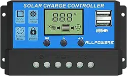
20A
RATED AMP(Max)
INPUT (Max)
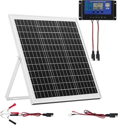
Ensure your battery has enough
voltage(>10.7V) for initial use.
125mm
132mm
50mm
70mm
125mm
132mm
50mm
70mm
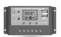
菜单键:用以切换参数显示界面,或长按5秒可进入或退出参数设置界
面。
+
-
/
上翻:在参数设置界面,轻按一次可使参数往上加一档。
下翻/灯:在参数设置界面,轻按一次使参数往下减一档。/负载输出为
24小时不间断模式时,可以短按此键手动关闭负载。
-
/
メニューポタン:パラメータ表⽰インタフェースを切り替え
る、または5sを⻑押ししてパラメータ設定を開始または終了
するために使⽤します。
+
-
/
アップ:パラメータ設定インターフェイスで、1回タップし
てパラメータにパラメータを追加します
+
ダウン/ライト:押すと値が減少します。/負荷出⼒に24時間の
作業モードを選択した場合は、このボタンを短く押した後で⼿
動でオン/オフを切り替えることができます。
-
/
MENU: Short press to switch between different display
interface.Long press to enter/exit setting mode.
+
-
/
UP: Press to increase value.
+
DOWN/Light Icon:Press to decrease value./If we choose 24
Hours working mode for load outputs, we can turn on/off the
consumer manually after short press this button.
-
/
Menü: Um die Parameter-Display-Schnittstelle zu wechseln,
oder lange 5s drücken, um die Parametereinstellungen
einzugeben oder zu verlassen.
+
-
/
Auf:drücken, um den Wert zu erhöhen.
+
DOWN / Light Icon: Drücken Sie diese Taste, um den Wert zu
verringern. / Wenn Sie den 24s. Betriebsmodus für die Lastausgänge
auswählen, können Sie den Verbraucher manuell ein- und ausschalten,
durch Sie diese Taste kurz drücken.
-
/
125mm
132mm
50mm
70mm
390W Max 12V バ ッ テ リ ー
780W Max 24V バ ッ テ リ ー
390W最⼤(12V电池)
780W最⼤(24V电池)
390WMax(12VBatterySystem)
780WMax(24VBatterySystem)
390W Max(12V Batteriesystem)
780W Max(24V Batteriesystem)
バッテリータイプ設定:
B01=開放型B02=密閉型B03=ゲル型
(このコントローラは鉛蓄電池にのみ対応しており、
リチウム電池やニッケル⽔素電池などの他の電池は
使⽤しないでください。)
电池类型设置
B01=开⼝型
B02=密封型
B03=胶体型
(本控制器只适⽤于铅酸电池,请勿使⽤其他电池
包括锂电池或者镍氢电池)
Battery Type
B01= OPEN
B02= AGM
B03= GEL
(It is only suitable for lead-acid batteries, not for
other batteries like nickel metal hydride batteries,
lithium-ion batteries.)
Batterietyp
B01= Offener
B02= Versiegelter
B03= Kolloidales
(Es ist nur für Blei-Säure-Batterien geeignet, nicht
für andere Batterien wie Nickel-Metallhydrid-
Batterien, Lithium-Ionen-Batterien.)
光控开关阀值(光伏板电压):当负载⼯作模式设置为
光控或时控时,控制器会检测光伏板电压来判断是否
开灯(运⾏负载设备),该值设置的越⾼,则⻩昏的
时候越早亮灯。(4V为系统设置值,不可调,此界⾯
⽤⼾不可⻅。)
光控开灯延时阀值(单位:秒):当控制器检测到光伏
电压低于设置阀值时,再延时10秒打开负载,此时间值
可⽤于防⽌夜间汽⻋⻋灯或者雷电⼲扰导致误判断⽽关
灯。(10秒为系统设置值,不可调,此界⾯⽤⼾不可
⻅。)
短路保护设置:某些感性或者容性负载在启动瞬间会有
较⼤电流,可能会触发控制器的短路保护⽽停⽌DC端输
出。短路保护默认为开启状态,不可调,此界⾯⽤⼾不
可⻅。
输出图标消失,表⽰此时发⽣了过流或者短路保护,
同时控制器⽴即关闭负载,待解除短路故障60秒后负
载端⾃动恢复重新输出,⽤⼾应及时检查并排除故
障。
<24V(12V系统)/<46V(24V系统)
B01=开⼝型
B02=密封型
B03=胶体型
浮充电压
13.7V(默认值,可调范围:12.7-15V)
10.7V(默认值,可调范围:9-11.3V)
12.6V(默认值,可调范围:11.5-13V)
⽤⼾需完整阅读此说明书并严格按照说明书进⾏安装及
使⽤,否则,不当操作可能会损坏产品甚⾄会危及附近其他
设备。
严禁私⾃拆卸、改造本产品,维修必须由专业⼈员或经本
公司授权认可⼈员进⾏。
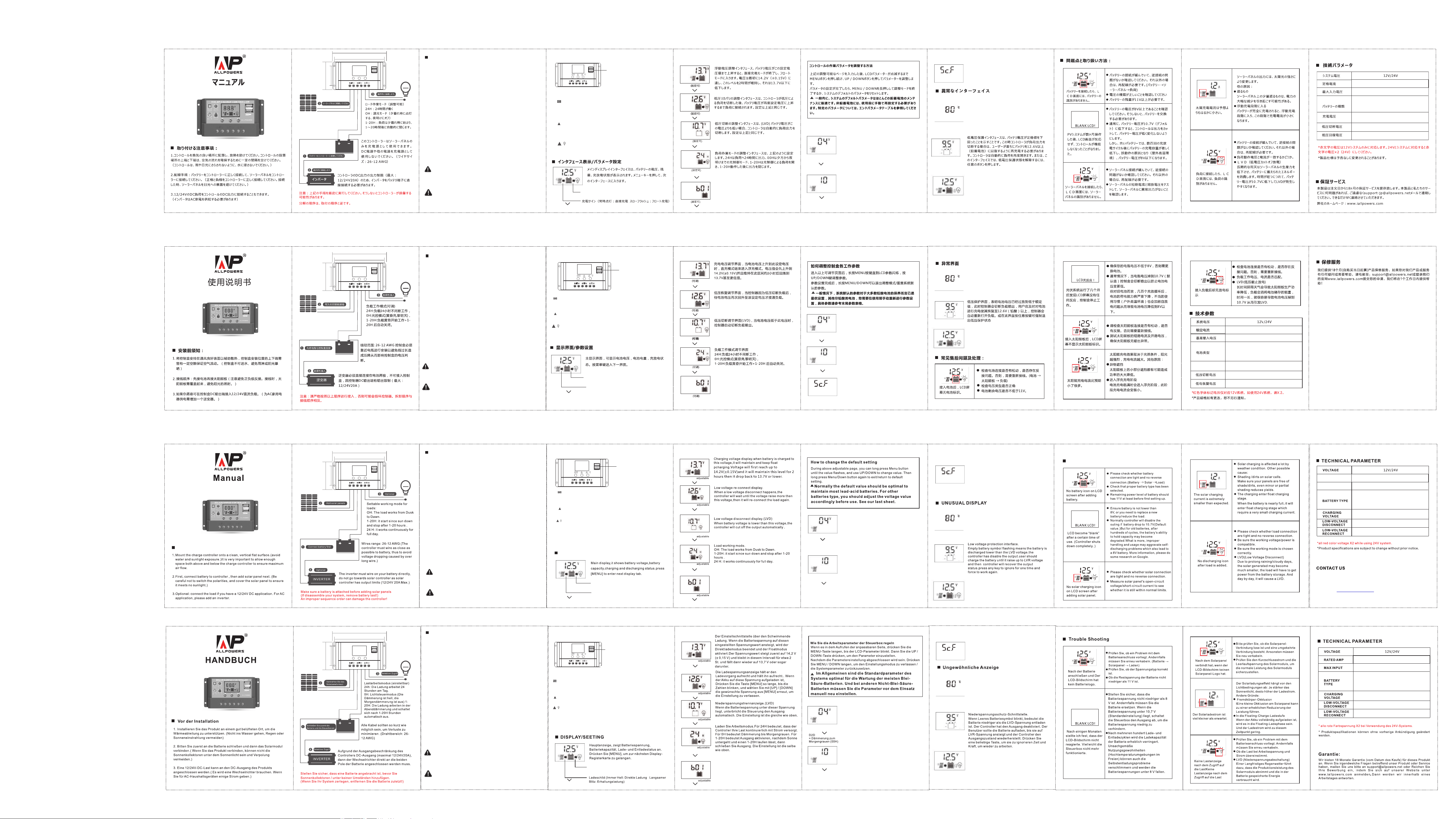
放电标⽰(常亮:负载输出模式开启中
熄灭:负载输出模式已关闭)
充电标⽰(常亮:直充阶段闪烁:浮充阶段)
USB输出:5V2.0Ax2
USB输出模式通电后即插即⽤,
不受时控或光控限制。
-
-
Discharging icon(Solid on: DC output mode is on
Disappear: DC output mode goes off)
Solar charging icon (Solid on: bulk charging stage
Flashing: float charging stage)
Ensure that you only use this product according to the
instructions in this manual, improper use may damage
the product or its environment.
Any modification or repair of this equipment or its
accessories must be carried out entirely by the
manufacturer or an authorized expert.
USB Output: 5V2.0A × 2
It always stay alive as long
as this controller is power
on.
D2D trigger value(Solar panel voltage)
When the work mode is D2D or Timer, the controller
will detect the solar panel voltage to decide
whether it is day or night, so to decide to enable
load output or not. The higher this value is, the
earlier it enables the load output.
(4V is default value, None adjustable, Not visible to
users. D2D= Dusk to Dawn OH load working mode)
D2D trigger delay value(Unit: seconds)
When the controller detect the solar panel voltage is
lower than trigger value, it will delay for 10s and
detect again to make sure night falls, then enable
the load output. Some car light or thunder lighting
will confuse the controller and make it thing it is
daytime, using this delay can prevent interference.
(10s is default value, None adjustable, Not visible to
users.)
Short-circuit protection setting
Some inductive or capacitive consumer will trigger
the short-circuit protection during start up and the
system will disable the DC output.
SC.F=OFF SC.N=ON
The default is ON.
(Default value,None adjustable, Not visible to
users)
High temperature anomaly interface, when the
controller's body temperature is too high, it will
enter stand-by mode and stop charging or
discharging, when temperature drop down to a safe
level, it will work again. Press any key to ignore for
one time and force it to work again.
(Default value,None adjustable, Not visible to
users.)
Over-current or short-circuit protection.
The load symbol disappear means a output over-
current or short-circuit protection occurs. The
controller now will disable the output and wait for
60s delay then try to recoveroutput again. User
should check and remove the trouble in time.
<24V( 12V Batteries System) /<50V(24V Batteries System)
B01 = OPEN
B02 = AGM
B03 = GEL
13.7V(Default, adjustable:12.7 - 15V)13.7V(Default, adjustable:12.7 - 15V)
10.7V(Default, adjustable:9 - 11.3V)
12.6V(Default, adjustable:11.5 - 13V)
+
⾼温异常界⾯,当控制器检测到温度过⾼时,会进⼊
停机,此时不充电也不放电,等待温度回落后再恢
复⼯作,按任意按键可直接退出停机界⾯进⼊正常
⼯作状态。
(80°C为默认值,不可调,此界⾯⽤⼾不可⻅)
Entlademarke
(Dauerlicht: Lastausgabemodus ist eingeschaltet
Aus: Lastausgabemodus ist aus)
USB-Ausgang: 5V2.0A × 2
Der USB-Ausgabemodus ist nach
dem Einschalten Plug-and-Play.
Nicht begrenzt durch Zeitsteuerung
oder Lichtsteuerung.
Stellen Sie sicher, dass Sie dieses Produkt nur gemäß den
Anweisungen in dieser Anleitung, unsachgemäßer Gebrauch
kann zu Schäden das Produkt oder seine Umgebung.
Jede Änderung oder Reparatur dieses Geräts oder seiner
Zubehör muss komplett vom Hersteller oder autorisierter
Sachverständiger.
<24V(12V Batteriesystem)/<50V (24V Batteriesystem)
B01 = OFFEN
B02 = AGM
B03 = GEL
13,7 V (Standard, einstellbar: 12,7 - 15 V)
10,7 V (Standard, einstellbar: 9 - 11,3 V)
12,6 V (Standard, einstellbar: 11,5 - 13 V)
Schaltschwelle der Lichtsteuerung (Spannung des
Photovoltaikmoduls): Wenn der Lastbetriebsmodus
auf Lichtsteuerung oder Zeitsteuerung eingestellt ist,
erkennt der Controller die Spannung des
Photovoltaikmoduls, um zu bestimmen, ob das Licht
eingeschaltet werden soll (Betrieb der
Lastausrüstung). schaltet sich früher ein, wenn es
dunkel ist. (4V ist der Systemeinstellungswert und
kann nicht angepasst werden. Diese Schnittstelle
kann nicht verwendet werden.)
Lichtgesteuerte Einschaltverzögerung (Einheit:
Sekunde): Wenn der Controller erkennt, dass die
Photovoltaikspannung niedriger als der eingestellte
Schwellenwert ist, verzögert er die Last um weitere
10 Sekunden. Dieser Zeitwert kann verwendet
werden, um Nachtlichter im Auto zu verhindern Oder
Donner und Blitz können zu Fehleinschätzungen
führen und das Licht ausschalten. (10 Sekunden ist
der Systemeinstellungswert, er ist nicht einstellbar.
Diese Schnittstelle ist nicht nützlich.)
Kurzschlussschutzeinstellung
Einige induktive oder kapazitive Verbraucher
lösen beim Start den Kurzschlussschutz aus und
das System deaktiviert den DC-Ausgang.
SC.F=OFF SC.N=ON die Voreinstellung ist ON.
(Standardwert,Keine einstellbar,Nicht sichtbar für
Benutzer)
Abnormale Schnittstelle bei hoher Temperatur.
Wenn der Controller erkennt, dass die Temperatur
zu hoch ist, wird er abgeschaltet und wird zu
diesem Zeitpunkt nicht geladen oder entladen.
Warten Sie, bis die Temperatur zurückkehrt und
nehmen Sie dann den Betrieb wieder auf. Drücken
Sie eine beliebige Taste, um das Shutdown-
Schnittstelle direkt Im normalen Arbeitszustand.
(80°C ist der Standardwert, nicht einstellbar, diese
Grenze kann nicht verwendet werden)
Das Ausgangssymbol verschwindet und zeigt an,
dass der Überstrom- oder Kurzschlussschutz zu
diesem Zeitpunkt wirksam ist.Gleichzeitig schaltet
die Steuerung die Last sofort ab, und die Last wird
60 Sekunden nach Beseitigung des
Kurzschlussfehlers negativ.Das Ladeterminal fährt
automatisch fort und gibt erneut aus.Der Benutzer
sollte den Fehler rechtzeitig überprüfen und
beheben.Barriere.
USB出⼒:5V2.0Ax2
USB出⼒モードはオンにすると、
プラグアンドプレイになり、時間
制御や照明制御による制限はござ
いません。
放電表⽰(消えない:負荷出⼒モードがオンになっている
消し:負荷出⼒モードがオフです)
この製品を安全に使えるために、組み⽴てるや使⽤される
前に説明書をよくお読みになります。もしそうでなけれ
ば、不適切な操作は製品を不具合が発⽣したり、周りのデ
バイスにもダメージを受ける可能性がございます。
この製品を個⼈的に分解または改造することは禁じられて
おり、補修は専⾨家または許可された担当者が⾏う必要が
ございます。
光制御ライトオン閾値(パネル電圧)は、負荷動作モ-
ドが光制御または時間制御に設定されている場合、
コントロ⼀ラはソ⼀ラ⼀パネルの電圧を検出して、
ライトをオンにするかどうかを決定します。この値
が⾼いほど、⼣暮れに早く点灯します。(システム
設定値、調整不可、このインターフェースはユーザ
ーには表⽰されません)
光制御ライトオン遅延閾値(単位:秒)、コントロ⼀ラ
はソ-ラ⼀パネルの電圧が設定された閾値よりも低い
ことを検出すると、負荷をオンするために10秒間遅
延します。この値は、夜間の⾞LEDライトや雷電の
⼲渉(誤った判断でライトを消す)が発⽣するのを防
ぐために使⽤できます。デフォルト値を使⽤するこ
とをお勧めします。(システム設定値、調整不可、
このインターフェースはユーザーには表⽰されませ
ん)
短絡保護設定:⼀部の誘導性/容量性の負荷は、起動時
に短絡保護をトリガーし、DC出⼒を無効にします。短
絡保護はデフォルトでオンに設定され、調整はできま
せん。モデルにより、画⾯は異なりますので、ご了承
ください。
⾼温異常のインタ⼀フェイスは、コントロ⼀ラは温度
が⾼すぎることを検出すると、シャットダウンに⼊
り、この時充電と放電されません。温度が動作するよ
うに戻って待って、通常の動作状態に⼊るために任意
のボタンを押すとシャットダウンイン⼣⼀フェイスか
ら⾶び出すことができます。
(⼀部のモデルにはこのインタフェ⼀スがありませ
ん。)
負荷アイコンの消え、出⼒過電流または短絡保護が
発⽣したことを⽰します。同時に、コントローラー
は出⼒を無効にします。短絡障害が除去されてから
60秒後、負荷端⼦は⾃動的に出⼒を再開します。
ユーザーは、その後、すぐに障害を確認して排除す
る必要がございます。
<24V(12Vバッテリーシステム)/<50V(24Vバッテリーシステム)
B01=開放型
B02=密閉型
B03=ゲル型
13.7V(既定値、調節可能エクステント:12.7-15V)
10.7V(既定値、調節可能エクステント:9-11.3V)
12.6V(既定値、調節可能エクステント:11.5-13V)
DISPLAY/SETTING
CAUTIONS FOR WIRING
TROUBLE SHOOTING
QUICK START INSTRUCTIONS
30A
30A
30A
30A