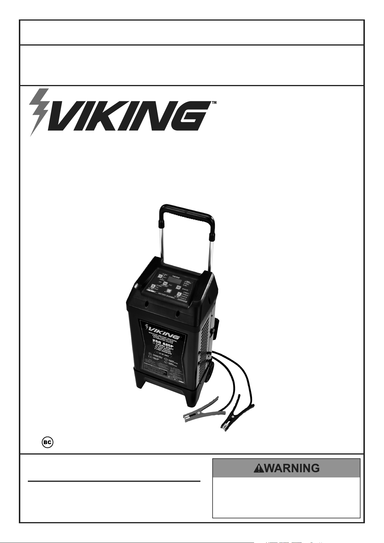
WHEELED BATTERY CHARGER,
ENGINE STARTER AND
ALTERNATOR TESTER
Visit our website at: http://www.harborfreight.com
email our technical support at: [email protected]
59466
Owner’s Manual & Safety Instructions
Save This Manual Keep this manual for the safety warnings and precautions, assembly,
operating, inspection, maintenance and cleaning procedures. Write the product’s serial number in the
back of the manual (or month and year of purchase if product has no number). Keep this manual and the
receipt in a safe and dry place for future reference. 23g
When unpacking, make sure that the product is intact
and undamaged. If any parts are missing or broken,
please call 1-888-866-5797 as soon as possible.
Copyright
©
2022 by Harbor Freight Tools
®
. All rights reserved.
No portion of this manual or any artwork contained herein may be reproduced in
any shape or form without the express written consent of Harbor Freight Tools.
Diagrams within this manual may not be drawn proportionally. Due to continuing
improvements, actual product may differ slightly from the product described herein.
Tools required for assembly and service may not be included.
read this material before using this product.
Failure to do so can result in serious injury.
SaVe tHiS ManuaL.
Page 2 For technical questions, please call 1-888-866-5797. 59466
SaFety OperatiOn MaintenanceSetup
table of contents
Safety ......................................................... 2
Specifications ............................................. 5
Setup .......................................................... 2
Operation .................................................... 7
Maintenance .............................................. 13
Parts List and Diagram .............................. 14
Warranty .................................................... 16
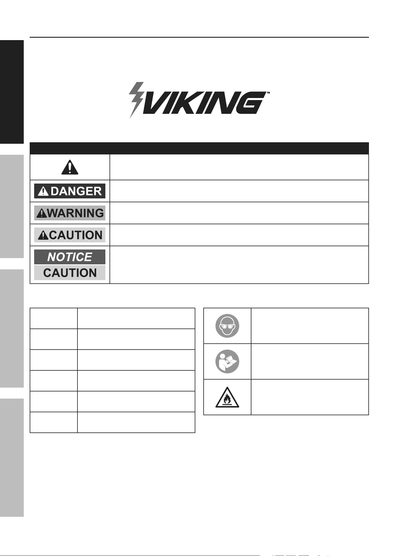
WarninG SyMBOLS anD DeFinitiOnS
This is the safety alert symbol. It is used to alert you to potential
personal injury hazards. Obey all safety messages that
follow this symbol to avoid possible injury or death.
Indicates a hazardous situation which, if not avoided,
will result in death or serious injury.
Indicates a hazardous situation which, if not avoided,
could result in death or serious injury.
Indicates a hazardous situation which, if not avoided,
could result in minor or moderate injury.
Addresses practices not related to personal injury.
V
Volts
~
Alternating Current
a
Amperes
cca
Cold Cranking Amps
rc
Reserve Capacity
ah
Ampere-hours
WARNING marking
concerning Risk of Eye Injury.
Wear ANSI-approved
splash-resistant safety goggles.
Read the manual before
set-up and/or use.
WARNING marking
concerning Risk of Fire.
Follow connection procedure.

Page 3For technical questions, please call 1-888-866-5797.59466
SaFetyOperatiOnMaintenance Setup
iMpOrtant SaFety inStructiOnS
1. SaVe tHeSe inStructiOnS –
This manual contains important safety and
operating instructions for this battery charger.
2. Do not expose charger to rain or snow.
3. Use of an attachment not recommended or sold
by the battery charger manufacturer may result in
a risk of fire, electric shock, or injury to persons.
4. To reduce risk of damage to electric
plug and cord, pull by plug rather than
cord when disconnecting charger.
5. An extension cord should not be used unless
absolutely necessary. Use of improper extension
cord could result in a risk of fire and electric shock.
If an extension cord must be used, make sure:
a. That pins on plug of extension cord
are the same number, size, and shape
as those of plug on charger;
b. That extension cord is properly wired
and in good electrical condition; and
c. That wire size is large enough for AC ampere
rating of charger as specified in Table A.
table a: recommended minimum aWG size
for extension cords for battery chargers
ac input rating, amperes*
aWG size of cord
Length of cord, feet
equal to or
greater than
But less
than
25 50 100 150
8 10 18 14 12 10
10 12 16 14 10 8
12 14 16 12 10 8
14 16 16 12 10 8
16 18 14 12 8 8
18 20 14 12 8 6
* If the input rating of a charger is given in watts rather than in
amperes, the corresponding ampere rating is to be determined by
dividing the wattage rating by the voltage rating – for example:
1250 watts/125 volts = 10 amperes
6. Do not operate charger with damaged cord or plug
– replace the cord or plug immediately.
7. Do not operate charger if it has received a sharp
blow, been dropped, or otherwise damaged in
any way; take it to a qualified serviceman.
8. Do not disassemble charger; take it to a
qualified serviceman when service or repair
is required. Incorrect reassembly may
result in a risk of electric shock or fire.
9. To reduce risk of electric shock, unplug charger
from outlet before attempting any maintenance or
cleaning. Turning off controls will not reduce this risk.
10. WARNING – RISK OF EXPLOSIVE GASES.
a. WORKING IN VICINITY OF A LEAD-ACID
BATTERY IS DANGEROUS. BATTERIES
GENERATE EXPLOSIVE GASES DURING
NORMAL BATTERY OPERATION. FOR THIS
REASON, IT IS OF UTMOST IMPORTANCE
THAT YOU FOLLOW THE INSTRUCTIONS
EACH TIME YOU USE THE CHARGER.
b. To reduce risk of battery explosion, follow these
instructions and those published by battery
manufacturer and manufacturer of any equipment
you intend to use in vicinity of battery.
Review cautionary marking on these
products and on engine.
11. PERSONAL PRECAUTIONS
a. Consider having someone close
enough by to come to your aid when
you work near a lead-acid battery.
b. Have plenty of fresh water and soap nearby in
case battery acid contacts skin, clothing, or eyes.
c. Wear complete eye protection and
clothing protection. Avoid touching
eyes while working near battery.
d. If battery acid contacts skin or clothing,
wash immediately with soap and water.
If acid enters eye, immediately flood eye with
running cold water for at least 10 minutes
and get medical attention immediately.
e. NEVER smoke or allow a spark or flame
in vicinity of battery or engine.
f. Be extra cautious to reduce risk of dropping
a metal tool onto battery. It might spark
or short-circuit battery or other electrical
part that may cause explosion.
g. Remove personal metal items such as rings,
bracelets, necklaces, and watches when
working with a lead-acid battery. A lead-
acid battery can produce a short-circuit
current high enough to weld a ring or the
like to metal, causing a severe burn.
h. Use charger for charging a LEAD-ACID battery
only. It is not intended to supply power to a
low voltage electrical system other than in a
starter-motor application. Do not use battery
charger for charging dry-cell batteries that
are commonly used with home appliances.
These batteries may burst and cause injury
to persons and damage to property.
i. NEVER charge a frozen battery.

Page 4 For technical questions, please call 1-888-866-5797. 59466
SaFety OperatiOn MaintenanceSetup
12. PREPARING TO CHARGE
a. If necessary to remove battery from vehicle
to charge, always remove grounded terminal
from battery first. Make sure all accessories in
the vehicle are off, so as not to cause an arc.
b. Be sure area around battery is well
ventilated while battery is being charged.
c. Clean battery terminals. Be careful to keep
corrosion from coming in contact with eyes.
d. Add distilled water in each cell until battery
acid reaches level specified by battery
manufacturer. Do not overfill. For a battery
without removable cell caps, such as valve
regulated lead acid batteries, carefully follow
manufacturer’s recharging instructions.
e. Study all battery manufacturer’s
specific precautions while charging and
recommended rates of charge.
f. Determine voltage of battery by referring
to vehicle owner’s manual and make sure
it matches output rating of battery charger.
If charger has adjustable charge rate,
charge battery initially at lowest rate.
13. CHARGER LOCATION
a. Locate charger as far away from
battery as DC cables permit.
b. Never place charger directly above
battery being charged; gases from battery
will corrode and damage charger.
c. Never allow battery acid to drip on
charger when reading electrolyte
specific gravity or filling battery.
d. Do not operate charger in a closed-in
area or restrict ventilation in any way.
e. Do not set a battery on top of charger.
14. DC CONNECTION PRECAUTIONS
a. Connect and disconnect DC output clips only
after setting any charger switches to “off” position
and removing AC cord from electric outlet.
Never allow clips to touch each other.
b. Attach clips to battery and chassis as indicated
in 15(e), 15(f), and 16(b) through 16(d).
15. FOLLOW THESE STEPS WHEN BATTERY
IS INSTALLED IN VEHICLE. A SPARK NEAR
BATTERY MAY CAUSE BATTERY EXPLOSION.
TO REDUCE RISK OF A SPARK NEAR BATTERY:
a. Position AC and DC cables to reduce risk of
damage by hood, door, or moving engine part.
b. Stay clear of fan blades, belts, pulleys, and
other parts that can cause injury to persons.
c. Check polarity of battery posts. POSITIVE
(POS, P, +) battery post usually has larger
diameter than NEGATIVE (NEG, N,–) post.
d. Determine which post of battery is
grounded (connected) to the chassis. If
negative post is grounded to chassis (as
in most vehicles), see (e). If positive post
is grounded to the chassis, see (f).
e. For negative-grounded vehicle, connect
POSITIVE (RED) clip from battery charger
to POSITIVE (POS, P, +) ungrounded post
of battery. Do not connect clip to carburetor,
fuel lines, or sheet-metal body parts.
f. For positive-grounded vehicle, connect
NEGATIVE (BLACK) clip from battery charger
to NEGATIVE (NEG, N, –) ungrounded post
of battery. Do not connect clip to carburetor,
fuel lines, or sheet-metal body parts.
g. When disconnecting charger, turn switches
to off, disconnect AC cord, and then
remove clip from battery terminal.
h. See operating instructions for
length of charge information.
16. FOLLOW THESE STEPS WHEN BATTERY
IS OUTSIDE VEHICLE. A SPARK NEAR THE
BATTERY MAY CAUSE BATTERY EXPLOSION.
TO REDUCE RISK OF A SPARK NEAR BATTERY:
a. Check polarity of battery posts. POSITIVE
(POS, P, +) battery post usually has a larger
diameter than NEGATIVE (NEG, N, –) post.
b. Connect POSITIVE (RED) charger clip to
POSITIVE (POS, P, +) post of battery.
c. Position yourself and free end of cable
as far away from battery as possible
– then connect NEGATIVE (BLACK)
charger clip to free end of cable.
d. Do not face battery when
making final connection.
e. When disconnecting charger, always do so in
reverse sequence of connecting procedure.
f. A marine (boat) battery must be removed and
charged on shore. To charge it on board requires
equipment specially designed for marine use.
17. Wear ANSI-approved splash-resistant
safety goggles and heavy-duty rubber
work gloves whenever connecting,
disconnecting, or working near battery.
Battery acid can cause
permanent blindness.
18. Do not use Engine Start setting to charge
batteries. Use to jump start only.
19. Maintain labels and nameplates on the charger.
These carry important safety information.
If unreadable or missing, contact
Harbor Freight Tools for a replacement.
20. This product is not a toy.
Keep it out of reach of children.

Page 5For technical questions, please call 1-888-866-5797.59466
SaFetyOperatiOnMaintenance Setup
21. Unplug the Battery Charger from its
electrical outlet before connecting its cables
to a battery, or performing any inspection,
maintenance, or cleaning procedures.
22. use this charger with flooded lead-acid batteries
only. When charging a maintenance-free battery,
always monitor the progress of the charge by
viewing the Battery Voltage / % on the Display.
Do not overcharge a maintenance-free battery.
23. Do not attempt to charge non-rechargeable
or defective batteries.
24. Do not charge more than one battery at one time.
25. Have your charger serviced by a qualified repair
person using only identical replacement parts.
This will ensure that the safety of
the charger is maintained.
26. Do not use charger while you are tired or under
the influence of drugs, alcohol or medication.
A moment of inattention while operating charger
may result in serious personal injury.
27. Before moving charger, disconnect power supply
and battery, then allow charger to cool.
28. People with pacemakers should consult their
physician(s) before use. Electromagnetic fields in
close proximity to heart pacemaker could cause
pacemaker interference or pacemaker failure.
In addition, people with pacemakers should:
• Avoid operating alone.
• Properly maintain and inspect to avoid
electrical shock.
• Properly ground power cord. Ground Fault Circuit
Interrupter (GFCI) should also be implemented
– it prevents sustained electrical shock.
29. The warnings, precautions, and instructions
discussed in this instruction manual cannot
cover all possible conditions and situations
that may occur. It must be understood by the
operator that common sense and caution are
factors which cannot be built into this product,
but must be supplied by the operator.
SaVe tHeSe inStructiOnS.
Grounding and ac power cord connection instructions
Charger should be grounded to reduce risk of electric
shock. Charger is equipped with an electric cord
having an equipment-grounding conductor and a
grounding plug. The plug must be plugged into an
outlet that is properly installed and grounded in
accordance with all local codes and ordinances.
DanGer – Never alter AC cord or plug provided
– if it will not fit outlet, have proper outlet installed
by a qualified electrician. Improper connection
can result in a risk of an electric shock.
cautiOn – risk of Fire or electric Shock.
Connect battery charger directly to grounding
receptacle (three-prong). An adapter should
not be used with battery charger.
Specifications
Input Electrical Rating
120 VAC / 60 Hz / 11.5 A Maximum continuous,
50A Maximum intermittent
Output
Charge Rate
Charge-2 A: 6/12VDC, 2A.
Charge-15A: 6/12VDC, 15A.
Boost: 6/12VDC, Duty-cycle operation, a cycle is:
50A-120 Seconds, 40A-60 Seconds, 30A-60 Seconds,
20A-60 Seconds, 30A-60 Seconds, 40A-60 Seconds
Engine Start 12V-START, 250A 10 Seconds On, 120 Seconds Off
Page 6 For technical questions, please call 1-888-866-5797. 59466
SaFety OperatiOn MaintenanceSetup
Setup
read the entire iMpOrtant SaFety inFOrMatiOn section at the beginning of this
manual including all text under subheadings therein before set up or use of this product.
tO preVent SeriOuS inJury:
DO nOt pLuG in cHarGer untiL DirecteD tO DO SO.
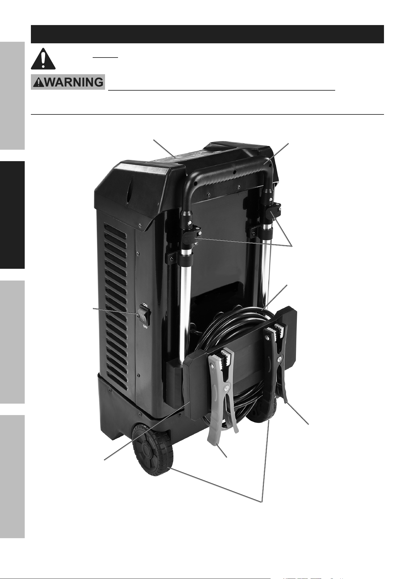
Functions
power
On/Off
Switch
retractable
Handle
positive (red) clip
negative
(black) clip
power cord
control panel
Handle
Lock tabs
Wheels
clip
Storage &
cord Wrap
panel
Page 7For technical questions, please call 1-888-866-5797.59466
SaFetyOperatiOnMaintenance Setup
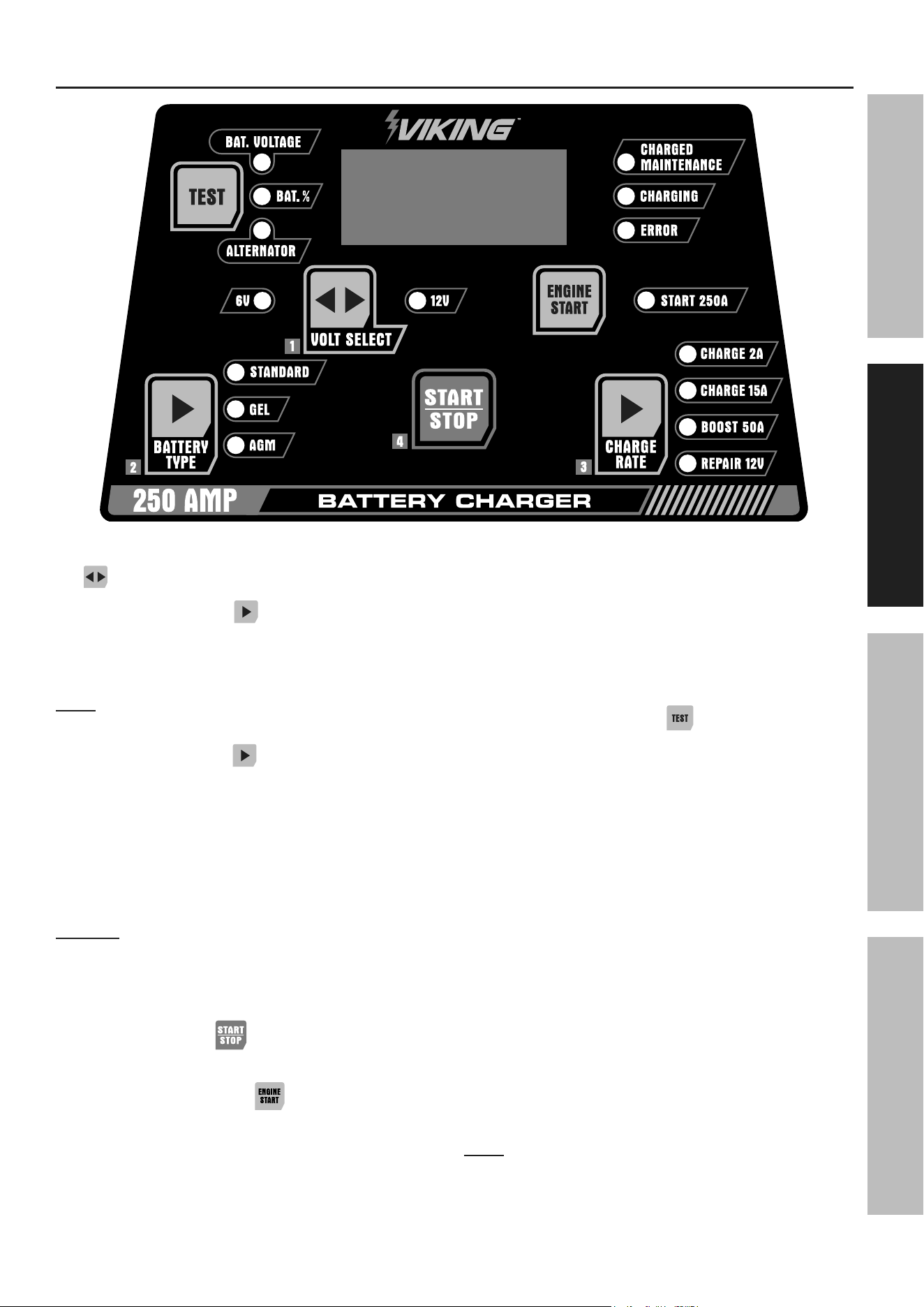
control panel
1. Volt Select: Battery Voltage selection button. Press
to cycle between the 6V and 12V selections.
2. Battery type: Press to cycle through
selections below. Selections are Standard,
Gel, and aGM (absorbed Glass Mat).
Button will not work during charging.
note: During charging, the battery voltage
will be slightly higher the rated voltage.
3. charge rate: Press to cycle through below
selections. Button will not work during charging.
a. cHarGe 2a - slow charge at 2A max.
b. cHarGe 15a - fast charge at 15A max.
c. BOOSt 50a - quick boost at 50A max.
d. repair 12V - slow charge when attempting
to repair a 12V lead-acid battery.
nOtice: repair 12V for use with 12V lead-acid
battery only. Read vehicle operator’s manual
before using this mode. Repairing process could
take from 2-8 hours to complete. Some deeply
damaged or shorted cells cannot be repaired.
4. Start/Stop - Press to Start
or Stop selected functions.
5. enGine Start: Press to select
Start 250a used only for engine start assist.
6. LeD indicators:
a. cHarGeD Illuminates when battery
Maintenance: is fully charged.
b. cHarGinG: Illuminates when
battery is charging.
c. errOr: Illuminates when a
problem has been detected.
7. teSt indicators: Press to cycle
through the selections below.
a. Bat. VOLtaGe: Battery voltage LED
illuminates when selected. Display
shows current battery voltage.
b. Bat. %: Battery % LED illuminates
when selected. Display shows
percentage of battery charged.
c. aLternatOr: LED illuminates when
selected. Display shows the Alternator
test result of Pass or Bad after tested.
8. Digital Display messages:
a. init: Charger is starting up.
b. reDy: Charger is ready to charge.
c. repr: Repair cycle.
d. cHrG: Charging in process.
e. anaL: Charger is analyzing battery.
f. FuLL: Battery is fully charged.
note: Error Messages can be found on page 13.
Page 8 For technical questions, please call 1-888-866-5797. 59466
SaFety OperatiOn MaintenanceSetup
preparing to charge
use this charger only on flooded lead-acid batteries.
Other batteries may be damaged or may overheat, leak, or catch fire.
DO nOt pLuG in cHarGer untiL DirecteD tO DO SO.
tO preVent SeriOuS inJury:
Wear anSi-approved splash-resistant safety goggles and heavy-duty rubber work gloves
whenever connecting, disconnecting, or working near battery.
Battery acid can cause permanent blindness.
1. If necessary to remove battery from vehicle to
charge, always remove grounded terminal from
battery first. Make sure all accessories in the
vehicle are off, so as not to cause an arc.
2. Make sure area around battery is well
ventilated while battery is being charged.
3. Clean battery terminals. Be careful to keep
corrosion from coming in contact with eyes.
4. Add distilled water in each cell until battery acid
reaches level specified by battery manufacturer.
Do not overfill. For a battery without
removable cell caps, such as valve
regulated lead acid batteries, carefully follow
manufacturer’s recharging instructions.
5. Study all battery manufacturer’s specific precautions
while charging and recommended rates of charge.
6. Determine voltage of battery by referring to vehicle
owner’s manual and make sure it matches output
rating of battery Charger. If Charger has adjustable
charge rate, charge battery initially at lowest rate.
7. A marine (boat) battery must be removed and
charged on shore. To charge it on board requires
equipment specially designed for marine use.
BatterieS WitH HyDrOMeter eye:
Do not depend on hydrometer eye to
determine battery charge level.
charger Location
1. Locate Charger as far away from
battery as DC cables permit.
2. Never place Charger directly above
battery being charged; gases from battery
will corrode and damage Charger.
3. Never allow battery acid to drip on Charger when
reading electrolyte specific gravity or filling battery.
4. Do not operate Charger in a closed-in
area or restrict ventilation in any way.
5. Do not set a battery on top of Charger.
taBLe B: cHarGinG rate/tiMe
Battery Size / rating
12V charge rate
charging time (based on battery at 50% charge)
Charge 2 A Charge 15 A Boost 50 A
Small batteries
(Motorcycle, Garden Tractor, etc.)
6-12 Ah 3 - 6 hr
Do not use these rates
for small batteries.
Cars / Trucks
200-315 CCA 40-60 RC 13 - 20 hr 2-1/2 - 4 hr 1/4 - 3/4 hr
315-550 CCA 60-85 RC 20 - 35 hr 4 - 7 hr 1/2- 2 hr
550-875 CCA 85-125 RC 35 - 55 hr 7 - 11 hr 1 1/2 - 3 hr
WarninG! tO preVent SeriOuS inJury, Fire, anD prOperty DaMaGe: Monitor charging during use.
raising or Lowering Handle
1. Unlock the Handle Lock Tabs on
both sides of the Handle.
2. Pull up the Handle to the desired height.
3. Lock the Handle Lock Tabs back in position.

Page 9For technical questions, please call 1-888-866-5797.59466
SaFetyOperatiOnMaintenance Setup
Operating instructions
read the entire iMpOrtant SaFety inFOrMatiOn section at the beginning of this
manual including all text under subheadings therein before set up or use of this product.
tO preVent SeriOuS inJury:
DO nOt pLuG in cHarGer untiL DirecteD tO DO SO.
charging Battery installed in Vehicle
a SparK near Battery May cauSe Battery eXpLOSiOn.
tO reDuce riSK OF a SparK near Battery FOLLOW tHeSe inStructiOnS eXactLy.
DO nOt pLuG in cHarGer untiL DirecteD tO DO SO.
tO preVent SeriOuS inJury:
Wear anSi-approved splash-resistant safety goggles and heavy-duty rubber work gloves
whenever connecting, disconnecting, or working near battery.
Battery acid can cause permanent blindness.
cautiOn! Do not use engine Start 250a
to charge batteries.
cOLD BatterieS: Begin charging at lowest rate,
increase rate as battery reaches normal temperature.
DO nOt cHarGe a FrOZen Battery.
1. Unplug Charger.
2. Position AC and DC cables to reduce risk of
damage by hood, door, or moving engine part.
3. Stay clear of fan blades, belts, pulleys, and
other parts that can cause injury to persons.
4. Check polarity of battery posts. POSITIVE
(POS, P, +) battery post usually has larger
diameter than NEGATIVE (NEG, N,–) post.
5. Determine which battery post is grounded
(connected) to the chassis. If negative post is
grounded to chassis, see a (below). If positive
post is grounded to the chassis, see b (below).
a. For negative-grounded vehicle
(as in most vehicles):
• Connect POSITIVE (RED) Clip from
battery Charger to POSITIVE (POS, P, +)
ungrounded post of battery.
• Connect NEGATIVE (BLACK) Clip to
vehicle chassis or engine block away
from battery. Do not connect clip to
carburetor, fuel lines, or sheet-metal
body parts. connect to a heavy gauge
metal part of the frame or engine block.
b. For positive-grounded vehicle:
• Connect NEGATIVE (BLACK) Clip
from battery Charger to NEGATIVE
(NEG, N, –) ungrounded post of battery.
• Connect POSITIVE (RED) Clip to vehicle
chassis or engine block away from battery.
Do not connect clip to carburetor,
fuel lines, or sheet-metal body parts.
connect to a heavy gauge metal part
of the frame or engine block.
6. Plug Charger into grounded 120VAC receptacle.
7. Turn Power Switch on. The display will show
init for one second then reDy when the
battery is detected and the Charger is ready.
nOtice: If an error message appears on the
Display, turn Power Switch off and correct the
problem before proceeding. See ERROR Messages
on page 13 for meaning and solution.
8. Battery voltage can be checked by pressing teSt
button. When Bat. Voltage LED is illuminated,
the Display will show the current battery voltage.
9. Press VOLt SeLect button until the voltage that
matches the rating of the vehicle battery illuminates.
10. Press Battery type button until the type that
matches the vehicle battery illuminates. AGM
is the most commonly used in automotive.
11. Press cHarGe rate button until the
desired charge rate illuminates.
cautiOn! Do not use engine Start 250a
to charge batteries.
12. Press Start/StOp button to start charging.
a. When charging starts, the
charging LED will flash.
b. Progress can be viewed by pressing
teSt button until the Bat. % LED is
illuminated. The Display will show how
much of the battery has been charged.

Page 10 For technical questions, please call 1-888-866-5797. 59466
SaFety OperatiOn MaintenanceSetup
note: Volt Select, Battery type and charge rate
cannot be changed during charging. To change selection,
press Start/StOp to stop, make new selection,
and then press Start/StOp to resume charging.
c. When the battery is fully charged, the
charged Maintenance LED will flash and
charging LED will extinguish. During this
stage the maintaining mode is activated and
will restart maintaining when necessary.
d. If the error LED illuminates, correct the problem
immediately. See ERROR Messages on
page 13 for Display message meaning.
e. After clearing the error, press Start/
StOp button to resume.
13. When finished, press Start/StOp button.
Turn Power Switch off, unplug power cord,
remove Clip from vehicle chassis, and then
remove Clip from battery terminal.
14. After use clean, then store the Charger
indoors out of children’s reach.
charging Battery Outside Vehicle
a SparK near Battery May cauSe Battery eXpLOSiOn.
tO reDuce riSK OF a SparK near Battery FOLLOW tHeSe inStructiOnS eXactLy.
DO nOt pLuG in cHarGer untiL DirecteD tO DO SO.
tO preVent SeriOuS inJury:
Wear anSi-approved splash-resistant safety goggles and heavy-duty rubber work gloves
whenever connecting, disconnecting, or working near battery.
Battery acid can cause permanent blindness.
cautiOn! Do not use engine Start 250a
to charge batteries.
cOLD BatterieS: Begin charging at lowest rate,
increase rate as battery reaches normal temperature.
DO nOt cHarGe a FrOZen Battery.
1. Unplug Charger.
2. Attach at least a 24-inch-long
6-gauge (AWG) insulated battery cable to
NEGATIVE (NEG, N, –) battery post.
3. Connect POSITIVE (RED) Charger Clip to
POSITIVE (POS, P, +) post of battery.
cautiOn! Do not face battery when
making final connection.
4. Position yourself and free end of battery
cable as far away from battery as possible –
then connect NEGATIVE (BLACK) Charger
Clip to free end of battery cable.
5. Plug Charger into grounded 120VAC receptacle.
6. Turn Power Switch on. The display will show
init for one second then reDy when the
battery is detected and the Charger is ready.
cautiOn!: If a message other than reDy is seen
on the display, turn Power Switch off and correct
the problem before proceeding. See ERROR
Messages on page 13 for meaning and solution.
7. Battery voltage can be checked by pressing teSt
button. When Bat. Voltage LED is illuminated,
the Display will show the current battery voltage.
8. Press VOLt SeLect button until the voltage that
matches the rating of the vehicle battery illuminates.
9. Press Battery type button until the type that
matches the vehicle battery illuminates. AGM
is the most commonly used in automotive.
10. Press cHarGe rate button until the
desired charge rate illuminates.
cautiOn! Do not use engine Start 250a
to charge batteries.
11. Press Start/StOp button to start charging.
a. When charging starts, the
charging LED will flash.
b. Progress can be viewed by pressing
teSt button until the Bat. % LED is
illuminated. The Display will show how
much of the battery has been charged.
note: Volt Select, Battery type and charge rate
cannot be changed during charging. To change section,
press Start/StOp to stop charging, make new
selection, and then press Start/StOp to
resume charging.
c. When the battery is fully charged, the
charged Maintenance LED will flash and
Charging LED will extinguish. During this
stage the maintaining mode is activated and
will restart maintaining when necessary.
d. If the error LED illuminates, correct the problem
immediately. See ERROR Messages on
page 13 for Display message meaning.
e. After clearing the error, press Start/
StOp button to resume.
12. When finished, press Start/StOp button to stop.
Turn Power Switch off and unplug power cord.

Page 11For technical questions, please call 1-888-866-5797.59466
SaFetyOperatiOnMaintenance Setup
13. When disconnecting Charger, always do
so in reverse sequence of connecting
procedure and break first connection while
as far away from battery as practical.
14. After use clean, then store the Charger
indoors out of children’s reach.
engine Starting (starting assist)
a SparK near Battery May cauSe Battery eXpLOSiOn.
tO reDuce riSK OF a SparK near Battery FOLLOW tHeSe inStructiOnS eXactLy.
DO nOt pLuG in cHarGer untiL DirecteD tO DO SO.
tO preVent SeriOuS inJury:
Wear anSi-approved splash-resistant safety goggles and heavy-duty rubber work gloves
whenever connecting, disconnecting, or working near battery.
Battery acid can cause permanent blindness.
Some vehicles with onboard computers may be damaged from the high-current starting output.
thoroughly read the vehicle service manual before using this procedure.
cautiOn! Do not use engine Start 250a
to charge batteries.
note: During extremely cold weather or when battery
is severely exhausted, charge the battery at 10A for
about five minutes before attempting to start engine.
1. Unplug Charger.
2. Position AC and DC cables to reduce risk of
damage by hood, door, or moving engine part.
3. Stay clear of fan blades, belts, pulleys, and
other parts that can cause injury to persons.
4. Determine which battery post is grounded
(connected) to the chassis. If negative post
is grounded to chassis, see a. If positive
post is grounded to the chassis, see b.
a. For negative-grounded vehicle
(as in most vehicles):
• Connect POSITIVE (RED) Clip from
battery Charger to POSITIVE (POS, P, +)
ungrounded post of battery.
• Connect NEGATIVE (BLACK) Clip to
vehicle chassis or engine block away
from battery. Do not connect clip to
carburetor, fuel lines, or sheet-metal
body parts. connect to a heavy gauge
metal part of the frame or engine block.
b. For positive-grounded vehicle:
• Connect NEGATIVE (BLACK) Clip
from battery Charger to NEGATIVE
(NEG, N, –) ungrounded post of battery.
• Connect POSITIVE (RED) Clip to vehicle
chassis or engine block away from battery.
Do not connect clip to carburetor,
fuel lines, or sheet-metal body parts.
connect to a heavy gauge metal part
of the frame or engine block.
5. Plug Charger into grounded
120VAC, 12A receptacle.
6. Turn Power Switch on. The display will show
init for one second then reDy when the
battery is detected and the Charger is ready.
nOtice: If a message other than reDy is seen
on the display, turn Power Switch off and correct
the problem before proceeding. See ERROR
Messages on page 13 for meaning and solution.
7. Press VOLt SeLect button until the voltage that
matches the rating of the vehicle battery illuminates.
8. Press Battery type button until the type
that matches the vehicle battery illuminates.
9. Press enGine Start button to
illuminate Start 250a LED.
10. Press Start/StOp button to start function.
Start 250a LED will light. Turn vehicle’s ignition
key. Once an engine starting attempt is detected,
a charge will be delivered for 10 seconds and then
stop for a mandatory cool down of 120 seconds.
Engine should start within 3 seconds. If it does
not start, turn off ignition and wait for Charger
and battery to cool before trying again.
note: Display will flash 120S / cOOL message during
cool down. Engine Start is not the same as jump
starting. Deeply discharged and larger vehicle batteries
may require more than one Engine Start application.
11. Once the Display shows reDy the
function can be tried again.
12. If engine fails to start, stop function and
press teSt to check the battery voltage:

Page 12 For technical questions, please call 1-888-866-5797. 59466
SaFety OperatiOn MaintenanceSetup
a. If the battery is under 9 volts or in extremely
cold weather, press cHarGe rate and run
BOOSt 50a to charge the battery for 5 minutes
before attempting to start the engine.
b. If engine fails to start after trying engine
start a few times, the battery could be
bad. Reconditioning the battery may
help. (See Repair 12V on page 12.)
note: If the engine turns over but does not start,
stop trying to start the engine. There is likely a
problem with the vehicle’s starting system. Have
a technician diagnose and correct the problem.
13. After the engine starts, turn Charger’s
Power Switch off and unplug the power cord.
14. Remove Clip from vehicle chassis, and
then remove Clip from battery terminal.
15. After use, clean and then store the Charger
indoors out of children’s reach.
test
1. Battery voltage can be tested by
pressing teSt button once.
a. When not jump starting and Bat. Voltage
LED is illuminated, the Display will
show the current battery voltage.
2. During charging, the progress of charging can
be viewed by pressing the teSt button twice.
a. When the Bat. % LED is illuminated,
the Display will show how much of
the battery has been charged.
3. The vehicle’s alternator can be checked by
pressing the teSt button a third time.
a. When not charging and the aLternatOr LED
is illuminated, the Display will show the output
voltage of the vehicle’s charging system.
• GOOD: Output is within normal
range (13.4 to 14.4 V).
• LOW: Output below 13.4V.
• Hi: Output over 14.4 V.
• If reading is LOW or Hi and the battery tests
ok, the vehicle’s electrical system should
be checked by a qualified technician.
b. Start the vehicle’s engine. Rev the engine
at 2000-2400 RPM for 15 seconds. Turn
off the engine after 15 seconds.
repair 12V
notice: repair 12V is a recovery mode for
repairing old, idle, stratified or sulfated batteries
and should be attempted on 12V batteries only.
1. Remove the battery from the vehicle.
2. Connect Charger to battery as described in
Charging Battery Outside Vehicle on page 10.
3. Turn Power Switch on. The display will show
init for one second then reDy when the
battery is detected and the Charger is ready.
cautiOn!: If a message other than reDy is seen
on the display, turn Power Switch off and correct
the problem before proceeding. See ERROR
Messages on page 13 for meaning and solution.
4. Press cHarGe rate until
repair 12V illuminates.
5. Press Start/StOp button to start charging
and the cHarGinG LED will flash.
• One repair cycle may take up to 8 hours.
• If the battery can be charged after 8 hours, the
Charger will automatically enter the cHarGe
15a mode (cHarGe 15a LED will flash).
6. When the battery is fully charged, the
cHarGeD Maintenance LED turn off.
7. When finished, turn Power Switch off
and unplug power cord.
8. When disconnecting Charger, always do
so in reverse sequence of connecting
procedure and break first connection while
as far away from battery as practical.
9. After use, clean and then store the Charger
indoors out of children’s reach.
Page 13For technical questions, please call 1-888-866-5797.59466
SaFetyOperatiOnMaintenance Setup
Maintenance instructions
procedures not specifically explained in this manual must
be performed only by a qualified technician.
tO preVent SeriOuS inJury: unplug the charger, disconnect any battery, and allow
charger to cool completely before performing any inspection, maintenance, or cleaning procedures.
tO preVent SeriOuS inJury FrOM tOOL FaiLure:
Do not use damaged equipment. if abnormal noise or vibration occurs,
have the problem corrected before further use.
1. BeFOre eacH uSe, inspect the general
condition of the Charger. Check for:
• loose hardware
• cracked or broken parts
• damaged electrical wiring or cable insulation
• any other condition that may
affect its safe operation.
2. aFter uSe, wipe external surfaces
of the tool with clean cloth.
3. WarninG! tO preVent SeriOuS inJury:
if the supply cord of this
charger is damaged, it must be replaced
only by a qualified service technician.
DO nOt Open cHarGer HOuSinG,
nO uSer-SerViceaBLe partS inSiDe.
troubleshooting
problem possible causes Likely Solutions
No Display reading. No power to Charger. Check power and cable outlet connections.
Charging voltage
not to full output.
1. Battery is partially charged.
2. Defective battery, will not hold full charge.
1. Continue charging battery.
2. Check and/or replace battery.
Follow all safety precautions whenever diagnosing or servicing the tool.
Disconnect power supply before service.
errOr Messages
Display
Message
possible problem Likely Solutions
OVER TEMP
Charger running too hot. Allow Charger to cool while plugged in.
The fan will help the Charger cool more quickly.
CONN-CLMP
1. No battery connected.
2. Battery voltage is less than 1V.
3. Battery clips connected together.
4. Battery clips damaged.
1. Clean battery posts and connect battery clips.
2. Defective battery, replace it.
3. Separate battery clips and connect them correctly.
4. Have technician replace battery clips.
CLMP-REVR Battery clip connected in reverse. Reconnect battery clips to correct battery posts.
WRG-VOLT
Battery voltage does not
match type selected.
Select Battery Type and Volt Select
that matches battery.
BAD-BATT
1. Battery fluctuates between
high and low voltages.
2. Battery cannot hold charge.
Charged % stays unchanged.
1. If 12V battery, run REPAIR cycle.
See Repair 12V on page 12.
2. Defective battery, replace it.

Page 14 For technical questions, please call 1-888-866-5797. 59466
SaFety OperatiOn MaintenanceSetup
pLeaSe reaD tHe FOLLOWinG careFuLLy
THE MANUFACTURER AND/OR DISTRIBUTOR HAS PROVIDED THE PARTS LIST AND ASSEMBLY DIAGRAM
IN THIS MANUAL AS A REFERENCE TOOL ONLY. NEITHER THE MANUFACTURER OR DISTRIBUTOR
MAKES ANY REPRESENTATION OR WARRANTY OF ANY KIND TO THE BUYER THAT HE OR SHE IS
QUALIFIED TO MAKE ANY REPAIRS TO THE PRODUCT, OR THAT HE OR SHE IS QUALIFIED TO REPLACE
ANY PARTS OF THE PRODUCT. IN FACT, THE MANUFACTURER AND/OR DISTRIBUTOR EXPRESSLY
STATES THAT ALL REPAIRS AND PARTS REPLACEMENTS SHOULD BE UNDERTAKEN BY CERTIFIED AND
LICENSED TECHNICIANS, AND NOT BY THE BUYER. THE BUYER ASSUMES ALL RISK AND LIABILITY
ARISING OUT OF HIS OR HER REPAIRS TO THE ORIGINAL PRODUCT OR REPLACEMENT PARTS
THERETO, OR ARISING OUT OF HIS OR HER INSTALLATION OF REPLACEMENT PARTS THERETO.
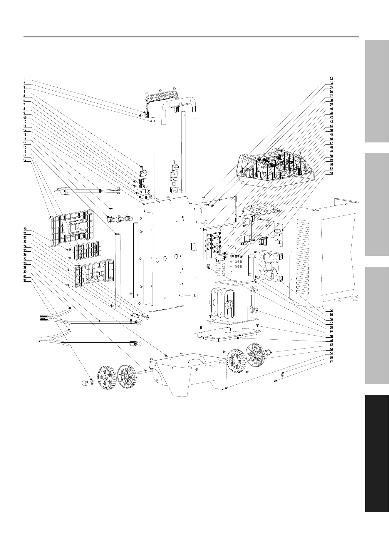
parts List and Diagram
parts List
part Description Qty
1 Handle 1
2 Tapping Screw 2
3 Upper Handle Bar 2
4 Handle Lock Button 2
5 Pinch Plate 2
6 Bar Holder 2
7 Check Nut 4
8 Hex Socket Machine Screw 2
9 Hex Socket Machine Screw 2
10 Tapping Screw 4
11 Handle Bar Fixing Seat 2
12 Rear Housing 1
13 Power Cord 1
14 Tapping Screw 6
15 Strain Relief 3
16 Lower Handle Bar 2
17 Wire Spool Seat 1
18 Wire Spool 1 1
19 Wire Spool 2 1
20 Tapping Screw 24
21 Screw 6
22 Spring Washer 12
23 Washer 12
24 Nut 7
25 Machine Screw 2
26 OT Cable Cord End Terminal 2
27 Hex Round Head Tapping Screw 35
28 Output Wire 2
29 Wheel Shaft 1
30 Negative Clip, Black 1
31 Positive Clip, Red 1
32 Wheel Clamping Ring 2
33 Tapping Screw 2
34 Isolation Column 1 7
35 Tapping Screw 7
part Description Qty
36 Radiator Support 1
37 Secondary SCR Radiator 1
38 Upper Panel 1
39 Circuit Board 1 1
40 Tapping Screw 6
41 Circuit Board 2 1
42 Control Panel 1
43 Isolation Column 2 4
44 Tapping Screw 10
45 Triple Combination Screw 10
46 Overload Device 3
47 Circuit Board Support 1
48 Connector 1
49 Washer 12
50 Spring Washer 6
51 Nut 6
52 Power On/Off Switch 1
53 Circuit Board 3 1
54 Front Housing 1
55 Fan 1
56 Tapping Screw 2
57 Fan Bracket 1
58 Triple Combination Screw 4
59 Iron-Core Transformer 1
60 Tapping Screw 8
61 Bottom Cover 1
62 Wheel Cover 2
63 Wheel 2
64 Lower Base 1
65 Serrated Gasket 2
66 In-Tube Limiter 2
67 Square Welded Nut 2
68 L-Type Radiator 2
69 Primary SCR Radiator 1
record product’s Serial number Here:
note: If product has no serial number, record month and year of purchase instead.
note: Some parts are listed and shown for illustration purposes only, and are not
available individually as replacement parts. Internal parts are not user-serviceable
and are not available. Specify UPC 193175471741 when ordering parts.
Page 15For technical questions, please call 1-888-866-5797.59466
SaFetyOperatiOnMaintenance Setup
assembly Diagram

26677 agoura road • calabasas, ca 91302 • 1-888-866-5797
Limited 90 Day Warranty
Harbor Freight Tools Co. makes every effort to assure that its products meet high quality and durability standards,
and warrants to the original purchaser that this product is free from defects in materials and workmanship for the
period of 90 days from the date of purchase. This warranty does not apply to damage due directly or indirectly,
to misuse, abuse, negligence or accidents, repairs or alterations outside our facilities, criminal activity, improper
installation, normal wear and tear, or to lack of maintenance. We shall in no event be liable for death, injuries
to persons or property, or for incidental, contingent, special or consequential damages arising from the use of
our product. Some states do not allow the exclusion or limitation of incidental or consequential damages, so the
above limitation of exclusion may not apply to you. THIS WARRANTY IS EXPRESSLY IN LIEU OF ALL OTHER
WARRANTIES, EXPRESS OR IMPLIED, INCLUDING THE WARRANTIES OF MERCHANTABILITY AND FITNESS.
To take advantage of this warranty, the product or part must be returned to us with transportation charges
prepaid. Proof of purchase date and an explanation of the complaint must accompany the merchandise.
If our inspection verifies the defect, we will either repair or replace the product at our election or we may
elect to refund the purchase price if we cannot readily and quickly provide you with a replacement. We will
return repaired products at our expense, but if we determine there is no defect, or that the defect resulted
from causes not within the scope of our warranty, then you must bear the cost of returning the product.
This warranty gives you specific legal rights and you may also have other rights which vary from state to state.