Installation, Start-up and Maintenance Manual
GEM-MFI Series
60 hz.
Ice-O-Matic®
11100 East 45th Ave
Denver, Colorado 80239
Part Number 9081403-01 Rev. H

Introduction
Ice-O-Matic® provides this manual as an aid to the end user and service technician in installation and
maintenance of the GEM-MFI Series ice machines. Do not attempt to perform installation, start-up or
maintenance unless you have read and fully understand this manual.
For a Service Provider, please reference our “Service and Support” tab at www.iceomatic.com
Keep this manual for future reference.
The GEM-MFI Series Service Parts Manuals are available separately.
Ice-O-Matic® icemakers and dispensers are not approved for outdoor installation.
WARNING: Always disconnect electrical power and shut off water supply whenever maintenance or
repairs are performed on the ice machine and related equipment.
CAUTION: Always wear protective eyewear and gloves whenever maintenance or repairs are
performed on the ice machine and related equipment.
Sustainability Program
Ice-O-Matic® is devoted to sustainability in every aspect of our business. To offset the carbon footprint of our
factory in Denver, we not only recycle materials in our packaging and manufacturing but also recycle our
industrial and office waste products.
Energy Efficiency
lce-O-Matic® is consistently working to improve the energy efficiency of our ice machines. We are
uncompromising in our pursuit of both productivity and energy efficiency and are continually looking for ways to
improve both, thereby delivering the best value in energy efficient products.
Ice-O-Matic® Warranty
Every Ice-O-Matic® ice maker is backed by a warranty that provides both parts and labor coverage. Ice-O-
Matic® warranties and water filter registrations should be filed online at www.iceomatic.com/warranty

Freight Claim Procedure
Important!
Inspect Promptly
This merchandise has been carefully inspected and packed in accordance with the carrier’s packing
specifications. Responsibility for safe delivery has been assumed by the carrier. If loss or damage occurs, you
as the consignee must file a claim with the carrier and hold the container for carrier’s inspection.
Visible Loss or Damage
Any external evidence of loss or damage must be fully described and noted on your freight bill or express
receipt and signed by the carrier’s agent. Claim should be filed on a form available from the carrier.
Concealed Loss or Damage
If loss or damage does not appear until merchandise has been unpacked, make a written request for
inspection by the carrier within 5 days of the delivery date. Then file a claim on a form from the carrier.
File Claim Without Delay
Do Not Return Damaged Merchandise to Ice-O-Matic®
Air and water cooled machines are hermetically sealed and contain fluorinated greenhouse gas
R404A (GWP 3922) or R449A (GWP 1282)
Models containing R449A are designated with the suffix, -49 (GEM0955A7-49)

Table of Contents
For The Installer (Guidelines) ...................................................................................................... Page 1
For The Installer (Applications) .................................................................................................... Page 5
For The Installer (Location) .......................................................................................................... Page 7
Remote Condenser ...................................................................................................................... Page 9
For The Plumber .......................................................................................................................... Page 13
For The Electrician ....................................................................................................................... Page 15
For The Installer (Completed Remote Installation) ...................................................................... Page 17
For The Installer (Check List) ...................................................................................................... Page 18
Start Up ........................................................................................................................................ Page 20
Cleaning and Sanitizing ............................................................................................................... Page 22
Condenser Cleaning…………………………………………………………………………………… Page 25
Service History ............................................................................................................................. Page 27

1
Installation Guidelines
For proper operation of the Ice-O-Matic® ice machine, the following installation guidelines must be followed.
Failure to do so may result in loss of production capacity, premature part failures, and may void all warranties.
Ambient Operating Air Temperatures: (Including Remote Condenser, See Below)
Minimum Operating Temperature: 50°F (10°C)
Maximum Operating Temperature 100°F (38°C)
Remote Condenser Maximum Operating Temperature 120°F (49°C)
Note: Ice-O-Matic® ice makers and dispensers are not approved for outdoor installation.
Incoming Water Supply
Minimum incoming water temperature: 40°F (4.5°C)
Maximum incoming water temperature: 100°F (38°C)
Minimum incoming water pressure: 20 psi (1.4 bar)
Maximum incoming water pressure: 80 psi (4.1 bar)
Note: If water pressure exceeds 80 psi a water pressure regulator must be installed.
Note: It is not recommended to connect a water softener because the ice may be more wet and slushy
than desired. Water Softeners add salinity, raising the freeze point resulting in “softer” ice. This
results in lower ice production.
Drains
All drain lines must be installed per local codes. Flexible tubing is not recommended. Route bin drain, vented
float overflow drain and water condenser drain individually to a floor drain. The use of condensate pumps for
draining water is not recommended by Ice-O-Matic®. Ice-O-Matic® assumes no responsibility for improperly
installed equipment.
Water Filtration
A water filter system should be installed with the ice machine.
Clearance Requirements
Self-contained air cooled ice machines must have a minimum of 6 inches (15cm) of clearance at the rear and
sides of the ice machine for proper air circulation.
Stacking
Ice-O-Matic® GEM-MFI Series ice machines are not designed to be stacked.
Dispenser Application
The GEM ice machine is approved for specific dispenser applications, reference page 5.
The MFI Series is not approved for dispenser applications.
Electrical Specifications
Refer to the serial plate at the rear of the ice machine to make sure proper voltage and circuit breaker size
have been supplied. Make sure the machine is on a dedicated circuit. The GEM-MFI Series are not supplied
with an electrical power cord and will need to be installed and wired per local electrical codes.
Adjustments
Level the machine within 1/8 inch in all directions. Adjust the cabinet or bin legs as required.
Check the bin control for proper operation.
Check the water level in the reservoir for proper adjustment.
Check the water regulating valve adjustment if water cooled
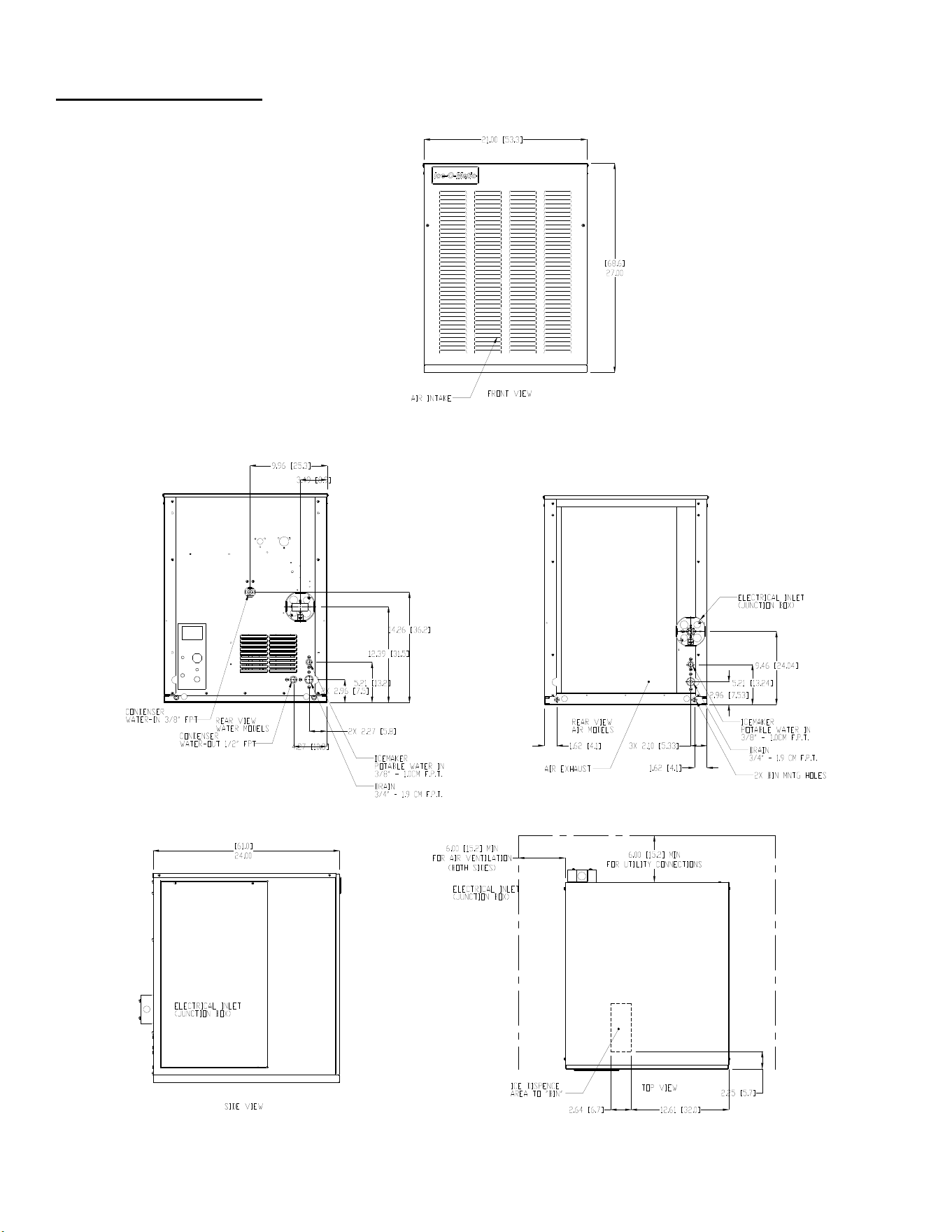
2
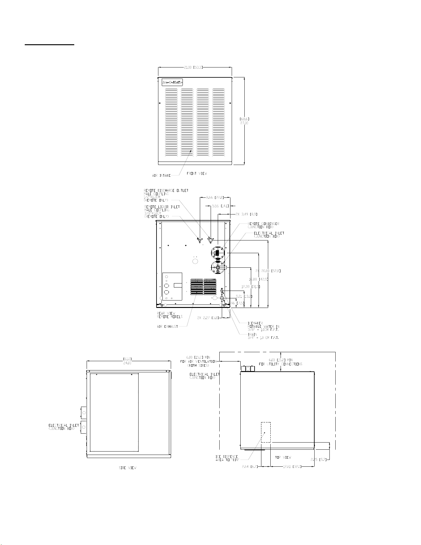
21” Air and Water Cooled
3
21” Remote
4
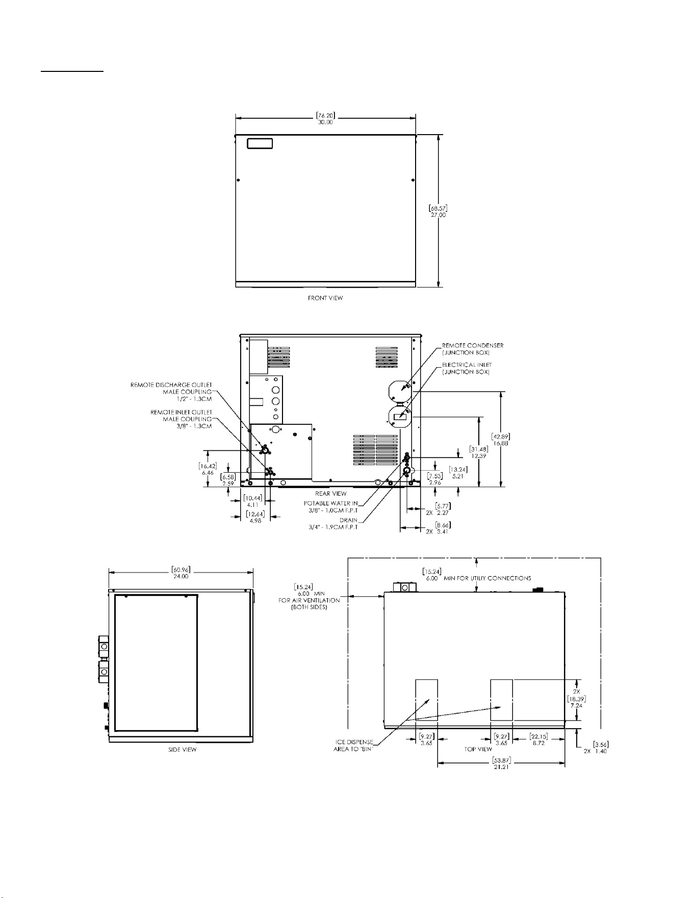
30” Remote
5
Bin Application
The GEM-MFI Series is designed to fit the following Ice-O-Matic® Bins
●B42, using Bin Top KBT 24
●B25, B40 or B55 using Bin Top KBT 19.
●B110, using Bin Top KBT 23 (one unit) or KBT 222 (two units).
●B700-30, B1000-48, B1300-48, B1325-60, B1600-60
Dispenser Application
The GEM Series can be placed on and used with certain ice and beverage dispensers listed below. Kits are
required for proper operation. The MFI Series is not approved for dispenser application.
Dispense
r
GEM0450 GEM0650
GEM0956 GEM1306A/R
GEM2006R
ICE-O-Matic® IOD150
KBT15022+KGEMDISP N/A
ICE-O-Matic
®
IOD200 or
IOD250
KBT25022+KGEMDISP KBT25030+KGEMDISP
Cornelius® ED or DF150
KBT15022+R629088514* N/A
Cornelius® ED or DF200
KBT25022+KGEMDISP KBT25030+KGEMDISP
Cornelius® ED or DF250
KBT25022+ KGEMDISP KBT25030+KGEMDISP
Cornelius
®
ED300
KGEMDISP+629087966* KBT25030+KGEMDISP
Cornelius® Flavor Fusion 255
KDIL-N-CFF and Cornelius
adapter 629088681 (Black)
Consult dispenser
manufacturer
Lancer® (Must have N in part
number) 30 inch 4500 model
KDIL-N-L and Lancer Part
Number 82-3491
Consult dispenser
manufacturer
* Cornelius® Part Number, If the Dispenser Model is Not Listed above, then is it NOT APPROVED
All the dispensers have automatic agitation to keep the ice from clumping. If agitation is too frequent, the Pearl
Ice will be damaged and will become difficult to dispense. The Ice-O-Matic® and Cornelius® dispensers need to
be set to 2 seconds on every 3 hours and the Lancer needs to be set to 4 seconds on, 150 seconds off.
The Ice-O-Matic® and most Cornelius® dispensers also have a restrictor plate at the outlet of the hopper. When
used, that plate should be adjusted to be 1.5 inch open to limit the speed of the Pearl Ice flows out during
dispensing.
6
Ice Machine Specifications
Model
Numbers
WxDxH (in.) Basic Electrical Condenser Min. Circuit
Ampacity
Max. Fuse
Size
Refrigerant
Charge oz.
404a
GEM0450A
21x24x27
115/60/1
Air 15.75 20 22
GEM0450W Water 14.35 20 18
GEM0650A Air 19.50 30 24
GEM0650W Water 18.30 30 19
GEM0650R RGA0501-HM 22.50 30 208
GEM0956A
208-230/60/1
Air 11.30 15 30
GEM0956W Water 10.80 15 22
GEM0956R RGA1061-HM 14.10 20 208
GEM1306A Air 15.80 20 30
GEM1306R RGA1061-HM 17.40 20 208
GEM2006R 30x24x27 RCA2061 24.40 40 208
MFI0500A
21x24x27
115/60/1
Air 15.75 20 22
MFI0500W Water 14.35 20 18
MFI0800A Air 19.50 30 24
MFI0800W Water 18.30 30 19
MFI0800R RGA0501-HM 22.50 30 208
MFI1256A
208-230/60/1
Air 11.30 15 30
MFI1256W Water 10.80 15 22
MFI1256R RGA1061-HM 14.10 20 208
MFI1506A Air 15.80 20 30
MFI1506R RGA1061-HM 17.40 20 208
MFI2306R 30x24x27 RCA2061 24.40 40 208

7
For the Installer (Location)
Ice-O-Matic® ice machines are designed to be installed indoors in a controlled environment. Install the ice
machine in a location where it has enough space around it to be accessible for service. A minimum of 6 inches
must be allowed at the back for air circulation on air cooled models. Try to avoid hot, dirty and crowded
locations. Be sure that the location of the machine is within the environmental limitations.
Storage Bin:
Remove the bin packaging. Tip the storage bin on its back, using parts of the packaging to protect the exterior
finish. Remove the skid and install the legs into the threaded holes in the bottom of the bin. Turn the leg
levelers all the way in preparation for leveling later. Return the bin to the upright position.
Note: Do not push the bin into position, but lift it there. Pushing a bin, especially one with ice in it, can cause
damage to the bin legs and mounts.
Install the appropriate bin top according to the instructions provided with the bin top.
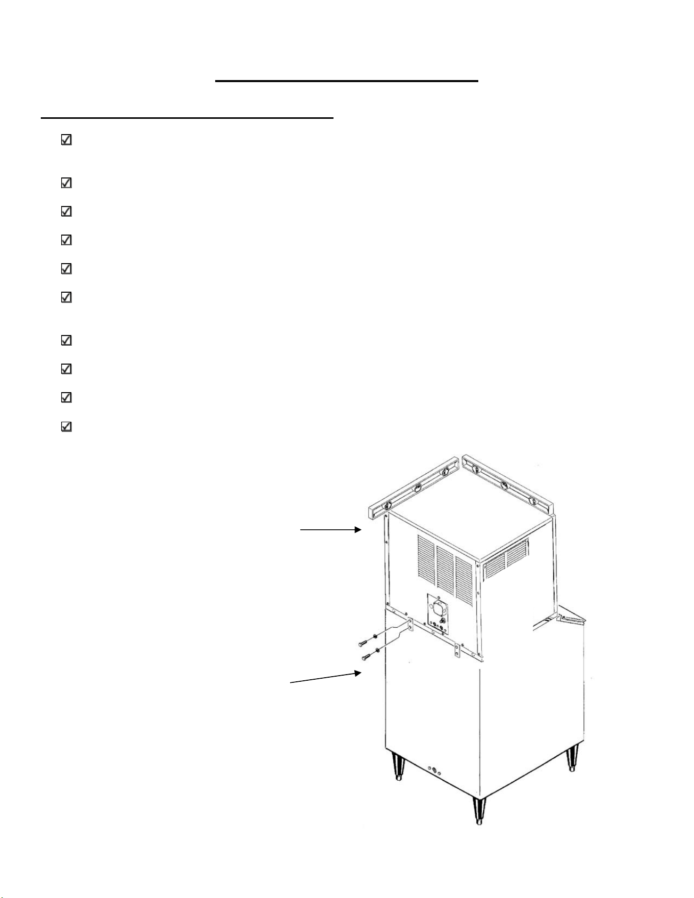
Ice machine:
The ice machine is heavy, so the use of a mechanical lift is recommended for lifting the machine high enough
to install on top of the bin. After the unit is placed on the bin, line it up so it is even with the back side. Secure
the ice machine to the bin with the hardware provided with the ice machine. Remove the front panel and
remove any shipping blocks or packaging material.
Proper functioning of the bin door requires the bin door, when it is opened, to be in a stable position. If the ice
machine is too far forward on the bin, the opened door may not be stable, resulting in an unexpected closing of
the bin door.
If the ice machine is to be mounted on a bin or dispenser other than an Ice-O-Matic®, refer to the
manufacturer’s instructions for machine mounting. Ice-O-Matic® will not be responsible for damage or injury
that results from unexpected closing of the bin door as a result of the ice machine being too far forward on the
bin.
Water Limitations:
An ice machine is a food manufacturing plant: it takes a raw material, water and transforms it into a food
product, ice. The purity of the water is very important in obtaining pure ice and maximizing product life. This
section is not intended as a complete resource for water related questions, but it does offer these general
recommendations:
●Check with a water treatment specialist for a water test and recommendations regarding water filters and
treatment.
●In most cases, the water used to make ice should be filtered or treated, depending upon the water.
There is no one type of water filter that is effective in all situations. That is why a water test in important.
RO Water Limitations:
Water conductivity must be no less that 35 microSiemens/cm.
Notice:
Ice-O-Matic® ice machines are designed and manufactured with the highest regard for safety and performance
and meet or exceed the standards of UL, NSF and CUL.
Ice-O-Matic® assumes no liability or responsibility of any kind for products manufactured by Ice-O-Matic® that
have been altered in any way, including the use of any part and/or other components not specifically approved
by Ice-O-Matic®.
Ice-O-Matic® reserves the right to make design changes and/or improvements at anytime. Specifications and
design are subject to change without notice.
8
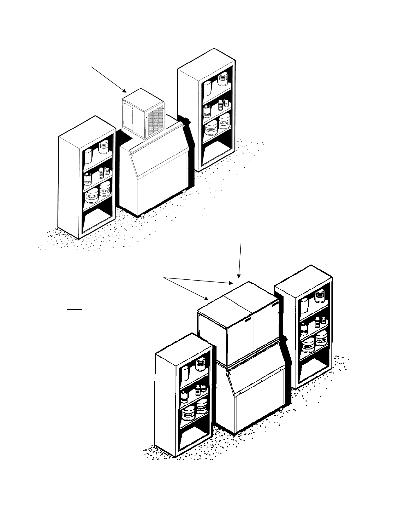
Allow 6 inches of Clearance
for Air Circulation
Allow 6 inches of Clearance
for Air Circulation
Two Units on One Bin
A proper installation locates the
ice machine indoors, but in a
place where the heat and noise it
produces are not objectionable.
Air cooled machines discharge
hot air out the back and must
have a minimum of 6 inches of
clearance behind the ice
machine.
Space for maintenance access is
also important. If two units are
placed side by side on a bin, side
access becomes even more
important.
9
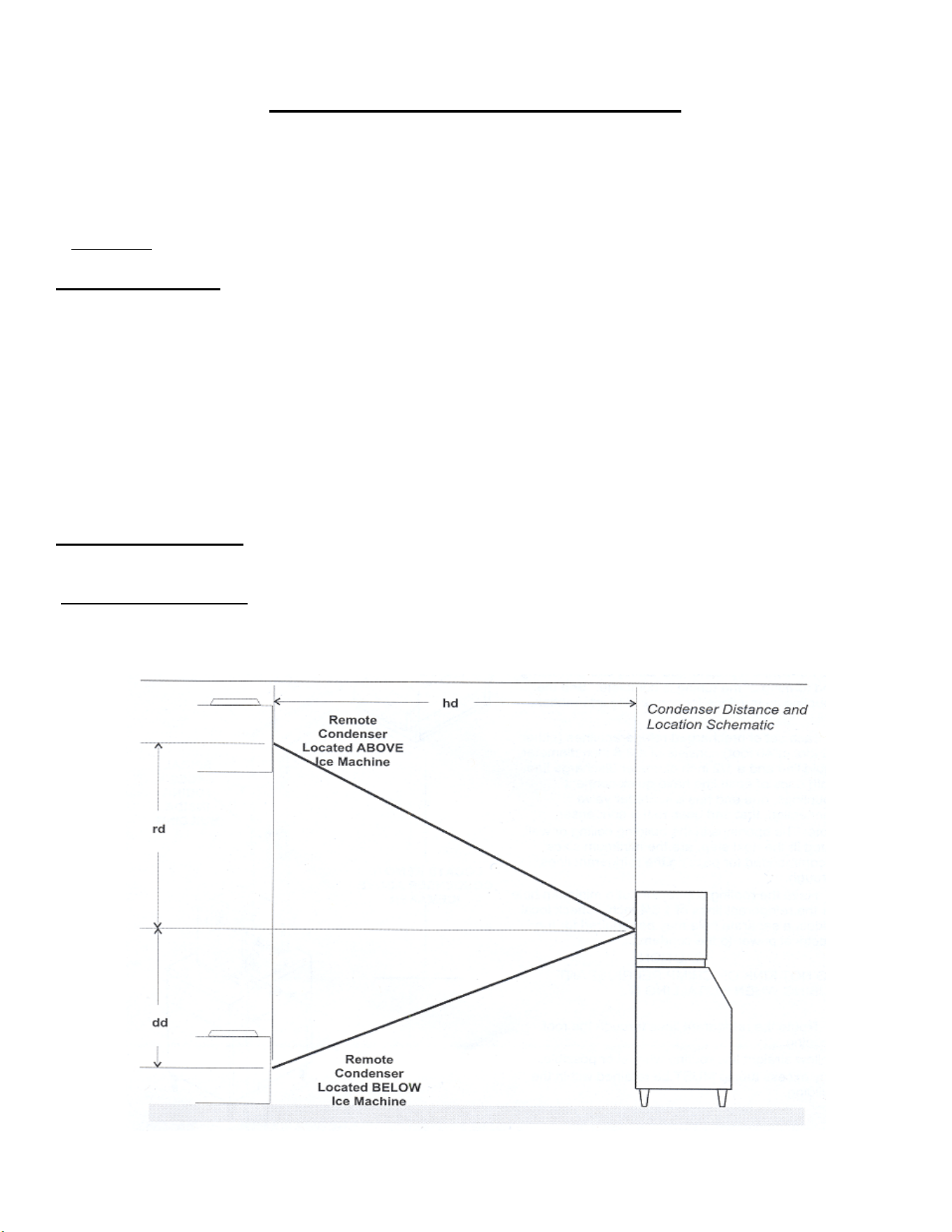
Remote Condenser Installation
Use the following for planning the placement of the remote condenser relative to the ice machine.
Location Limits: Remote condenser location must not exceed ANY of the following:
● Maximum rise from the ice machine to the remote condenser is 35 physical feet.
● Maximum drop from the ice machine to the remote condenser is 15 physical feet.
● Physical line set maximum length is 100 feet.
● Calculated line set length maximum is 150 feet.
Calculation Formula
● Drop = dd x 6.6 (dd= distance in feet)
● Rise = rd x 1.7 (rd = distance in feet)
● Horizonal Run = hd x 1 (hd = distance in feet)
● Calculation: Drop(s) + Rise(s) + Horizontal Run = dd+rd+hd=Calculated Line Length
Configurations that do NOT meet these requirements must receive written authorization from
Ice-O-Matic®. This includes multipass or rack system remote condensers.
Do NOT:
● Route a line set that rises, then falls, then rises.
● Route a line set that falls, then rises, then falls.
Calculation Example 1:
The remote condenser is to be located 5 feet below the ice machine and then 20 feet away horizontally.
(5 feet x 6.6=33 feet) + (20 feet) = 53 feet. This location would be acceptable.
Calculation Example 2: The remote condenser is to be located 35 feet above the ice machine and then 100
feet away horizontally. (35 feet x 1.7=59.5 feet) + (100 feet) = 159.5 feet. 159.5 feet is greater than the 150
maximum is NOT acceptable.
10
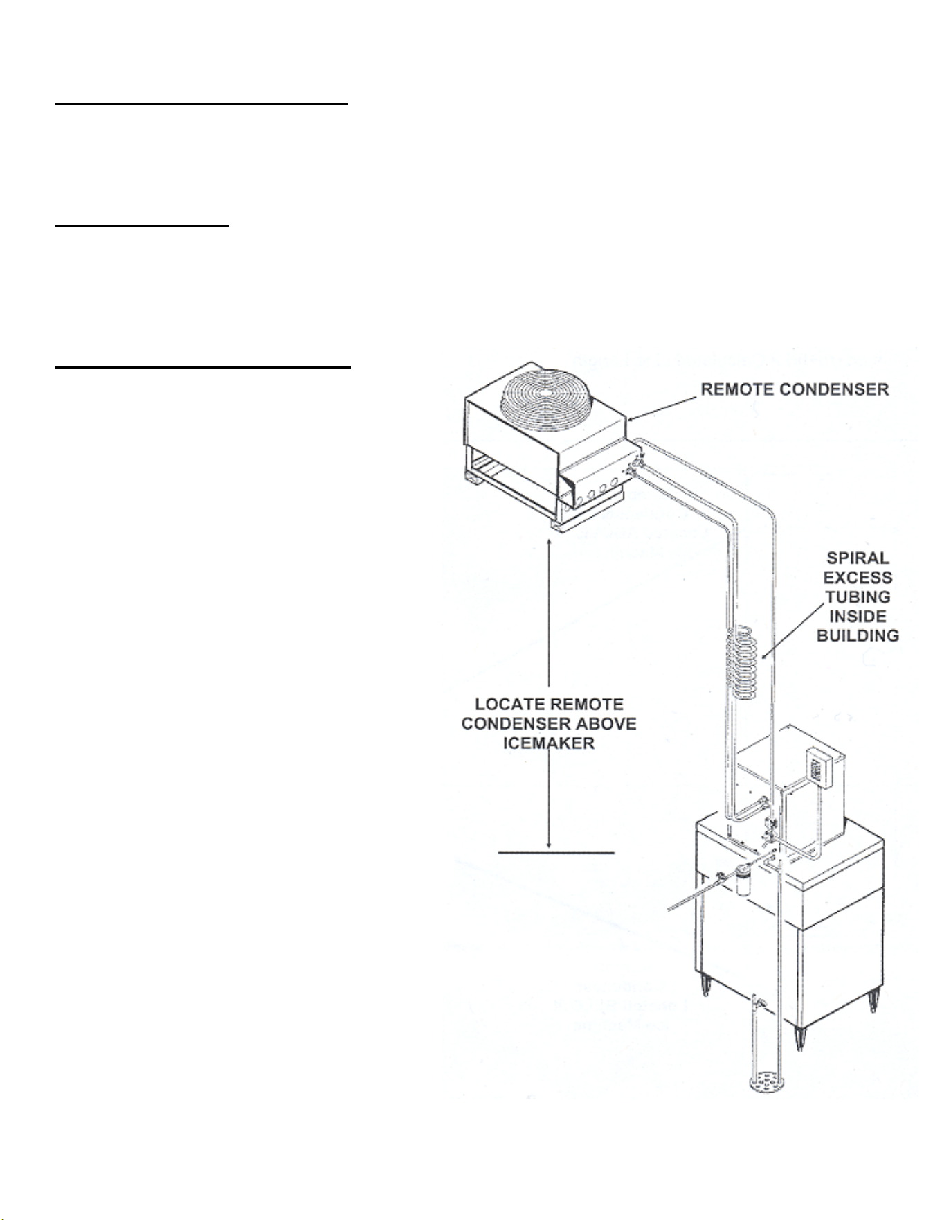
Remote Condenser Location
Limited to a 25 foot or a 40 foot length of precharged refrigerant tubing connecting the ice machine to the
remote condenser. The remote condenser must be above or level with the ice machine. Select the best
available location, protecting the remote condenser from extremes of dirt, dust and sun. Meet all applicable
building codes. Usually the services of a licensed electrician are required.
Roof Attachment
1. Install and attach the remote condenser to the roof of the building, using the methods and practices of
construction that conform to the local building codes, including having a roofing contractor secure the
remote condenser to the roof.
2. Have an electrician connect the remote condenser fan motor to the ice machine, using the junction box at
the back of the ice machine.
Precharged Line Set Routing
CAUTION: Do not connect the precharged
tubing until all routing and forming of the
tubing is complete. See the coupling
instructions for connecting information.
1. Each set of preharged tubing refrigerant lines
consists of a 3/8 diameter liquid line and a 1/2
inch diameter discharge line. Both ends of
each line have quick connect couplings, one
end has a Schrader valve connection, that end
goes to the condenser.
Note: The openings in the building ceiling or
wall, listed in the next step, are the minimum
sizes recommended for passing the refrigerant
lines through.
2. Have the roofing contractor cut a minimum
hole for the refrigerant lines of 1.750 inch.
Check local codes, a separate hole may be
required for the electrical power to the
condenser.
CAUTION: DO NOT KINK OR CRIMP
REFRIGERANT TUBING WHEN
INSTALLING IT.
3. Route the refrigerant lines through the roof
opening. Follow straight line routing whenever
possible. Any excess tubing MUST remain
within the building.
4. Spiral the excess length of precharged tubing
inside the building. Use a horizontal spiral
(does not need to be as tight as illustrated) to
avoid any traps in the lines.
5. Have the roofing contractor seal the holes in
the roof per local codes.
CAUTION: The couplings on the sets of
precharged lines are self sealing when
installed properly. Carefully follow the instructions:
11
Typical Installation
REMOTE CONDENSER
ICE MACHINE
12
Coupling Instructions
Initial Connections:
1. Remove the protector caps and plugs. Wipe the seats and threaded surfaces with a clean cloth to be
certain that no foreign matter remains on them.
2. Lubricate the inside of the couplings, especially the O-Rings with refrigerant oil.
3. Position the fittings on the correct connections on the remote condenser
and ice machine.
●The 1/2 inch discharge line (Schrader valve end) goes to the remote
condenser fitting marked “Discharge Line”
●The 3/8 inch liquid line (Schrader valve end) goes to the remote
condenser fitting marked “Liquid Line”.
●The 1/2 inch discharge line goes to the ice machine fitting marked
“Discharge Line”.
●The 3/8 inch liquid line goes to the ice machine fitting marked “Liquid
Line”.
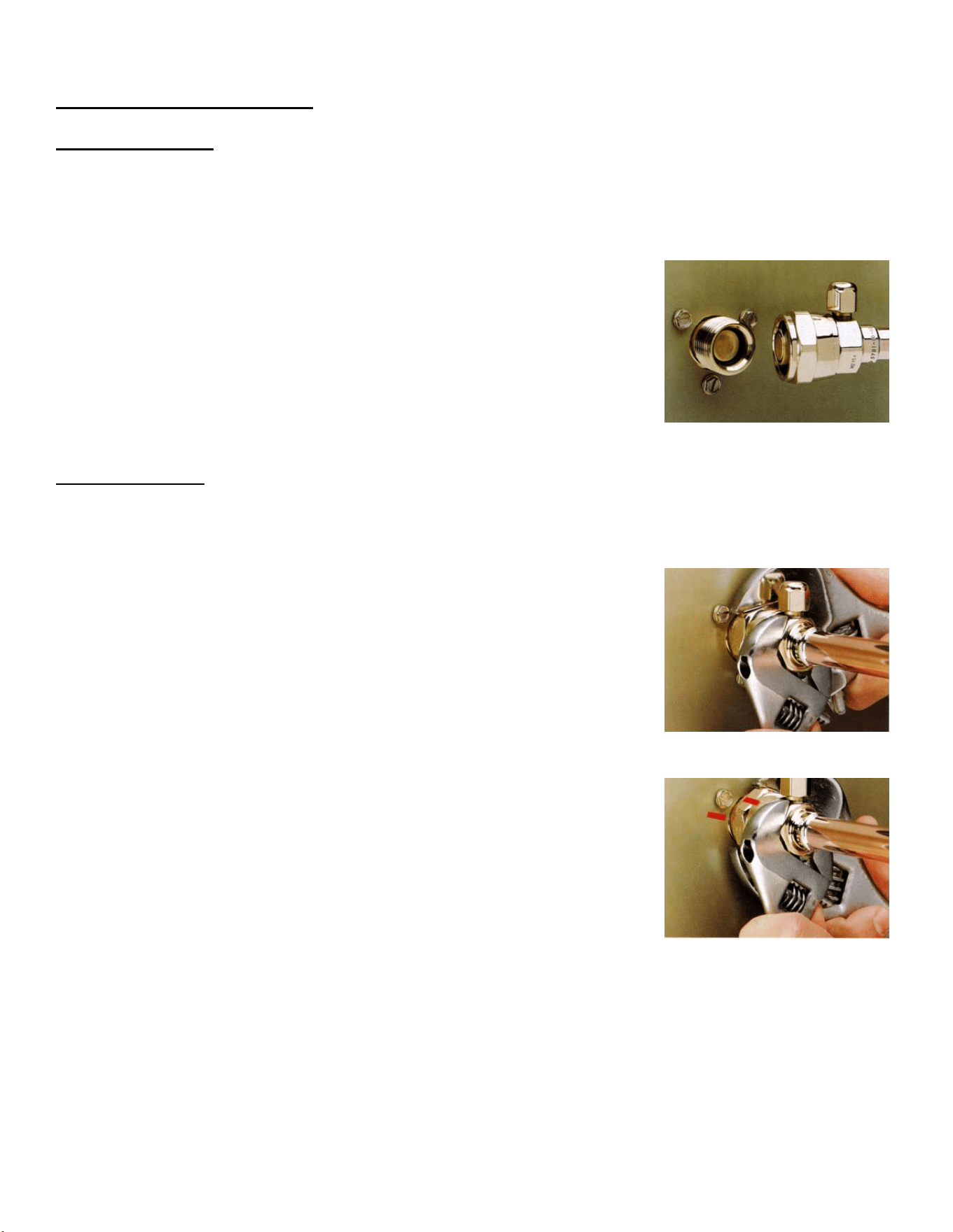
Final Connections
4a. Begin by tightening the couplings together by hand. Continue to turn the swivel nuts by hand until it is
certain that the threads are properly engaged.
4b. Using two wrenches, one to rotate the swivel nut and one to hold the tubing, tighten each coupling.
It is CRITICAL that ONLY the NUT on the precharged tube be turned or
the diaphragms will be torn loose by the piercing knives and be loose in
the refrigeration system causing severe operational problems.
Note: As the coupling is tightened, the diaphragms in the quick connect
couplings will begin to be pierced. As that happens, there will be
increased resistance to tightening the swivel nut.
4c. Continue tightening the swivel until it bottoms out or a very definite
increase in resistance is felt (no threads should be showing). Do NOT
over tighten.
5. Using a marker or pen, mark a line lengthwise from the coupling union nut
to the bulkhead. Then tighten the coupling and additional 1/4 turn. As
the nut turns, the line will show when the 1/4 turn is made.
6. After all connections are made, and after the king valve has been opened
(do not open at this time) check the couplings for leaks.
13
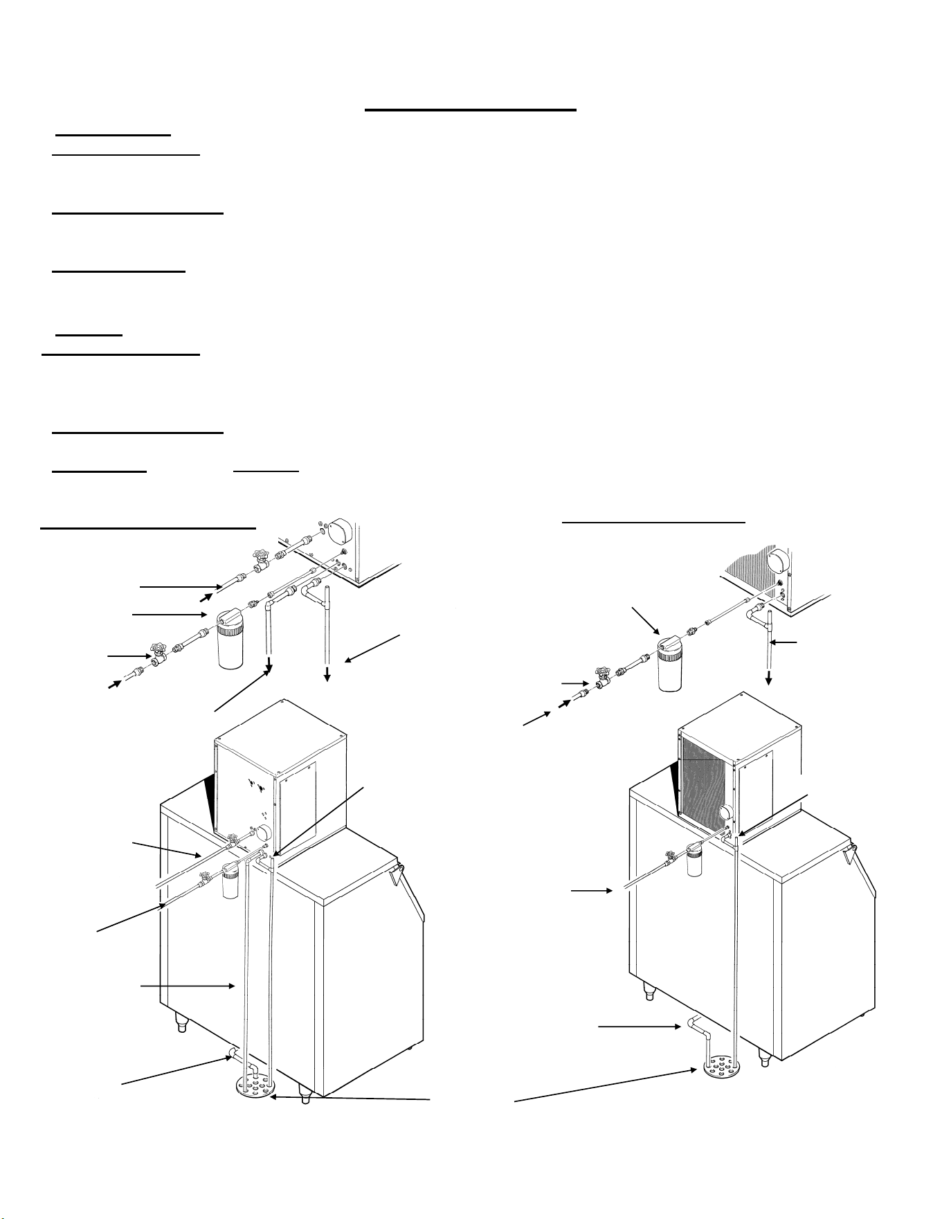
For the Plumber
Water Inlet:
●Air Cooled Models The recommended water supply is clean, cold water. Use 3/8 inch O.D. copper tubing,
connect to the 3/8 inch FPT at the back of the cabinet. Install a hand valve near the machine to control the
water supply.
●Water Cooled Models A separate 3/8 inch O.D. copper line is recommended, with a separate hand valve to
control it. Connect to the 3/8 inch FPT condenser inlet at the back of the cabinet. The water pressure to all
lines must always be above 20 psig, and below 80 psig.
●Water Treatment In most areas, a water filter of some type will be useful. In areas where the water is highly
concentrated with minerals, the water should be tested by a water treatment specialist, and the
recommendations of the specialist regarding filtration and/or treatment should be followed.
Drains
●Air Cooled Models Connect a rigid drain tube to the ¾ FPT drain fitting at the back of the cabinet. The drain is
a gravity type, and a ¼ inch per foot fall is the minimum acceptable pitch for the drain. There should be a vent
at the highest point of the drain line, and the ideal drain receptacle would be a trapped and vented floor drain.
Use only ¾ inch rigid tubing.
●Water Cooled Models Connect a separate drain line to the ½ inch condenser drain connection at the back of
the cabinet. Do not vent this drain.
●Storage Bin Connect a separate gravity type drain line to the ice storage bin drain. Vent this drain if there is a
long horizontal run from the bin to the floor drain. Insulation of this drain line is recommended.
WATER COOLED MODELS
AIR COOLED MODELS
Floor Drain
Water Inlet
Vented Drain
Water Filter
Condenser Drain
Water In
Hand Valve
Bin Drain
Condenser Inlet
Hand Valve
Bin Drain
Condenser Drain
Vented Drain
Condenser Inlet
Water In
Vented Drain
Vented Drain
Water Filter
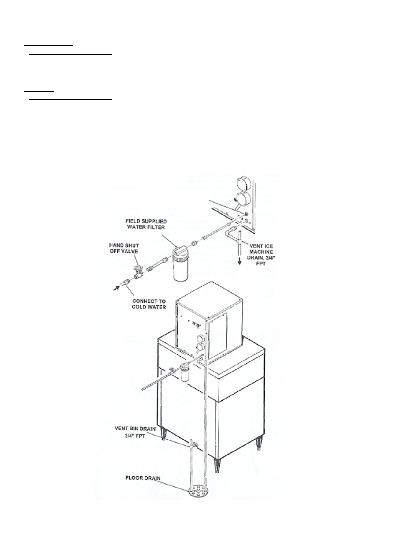
14
Water Inlet
●Remote Cooled Models
The recommended water supply is cold water. Use 3/8 inch O.D. copper tubing, connect to the 3/8 FPT on the
back of the cabinet. Install a hand valve near the machine to control the water supply.
Drains
●Remote Cooled Models
There is one 3/4 inch FPT drain at the back of the cabinet; the drain line is of the gravity type, and 1/4 inch per
foot fall is an acceptable pitch for the drain tubing. There should be a vent at the highest point of the drain line,
and the ideal drain receptacle would be a trapped and vented floor drain. Use only ¾ inch rigid tubing.
Storage Bin
Install a separate gravity type drain. Insulation of this drain line is recommended.
Water Inlet 3/8 FPT
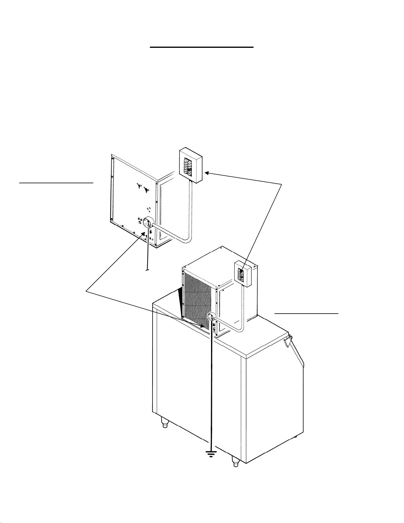
15
For the Electrician
Check the ice machine nameplate (located on the back panel) for the voltage requirements, and minimum
circuit ampacity. The ice machine requires a solid chassis to earth ground.
Connect the ice machine to its own electrical circuit so it is individually fused. Voltage variation must remain
within the limitations, even under starting conditions.
Note: All external wiring must conform to national, state and local electrical codes.
The use of a licensed electrician is required to perform the electrical installation.
Power
Supply
Electrical Inlet
Water Cooled Models
Air Cooled Models
16
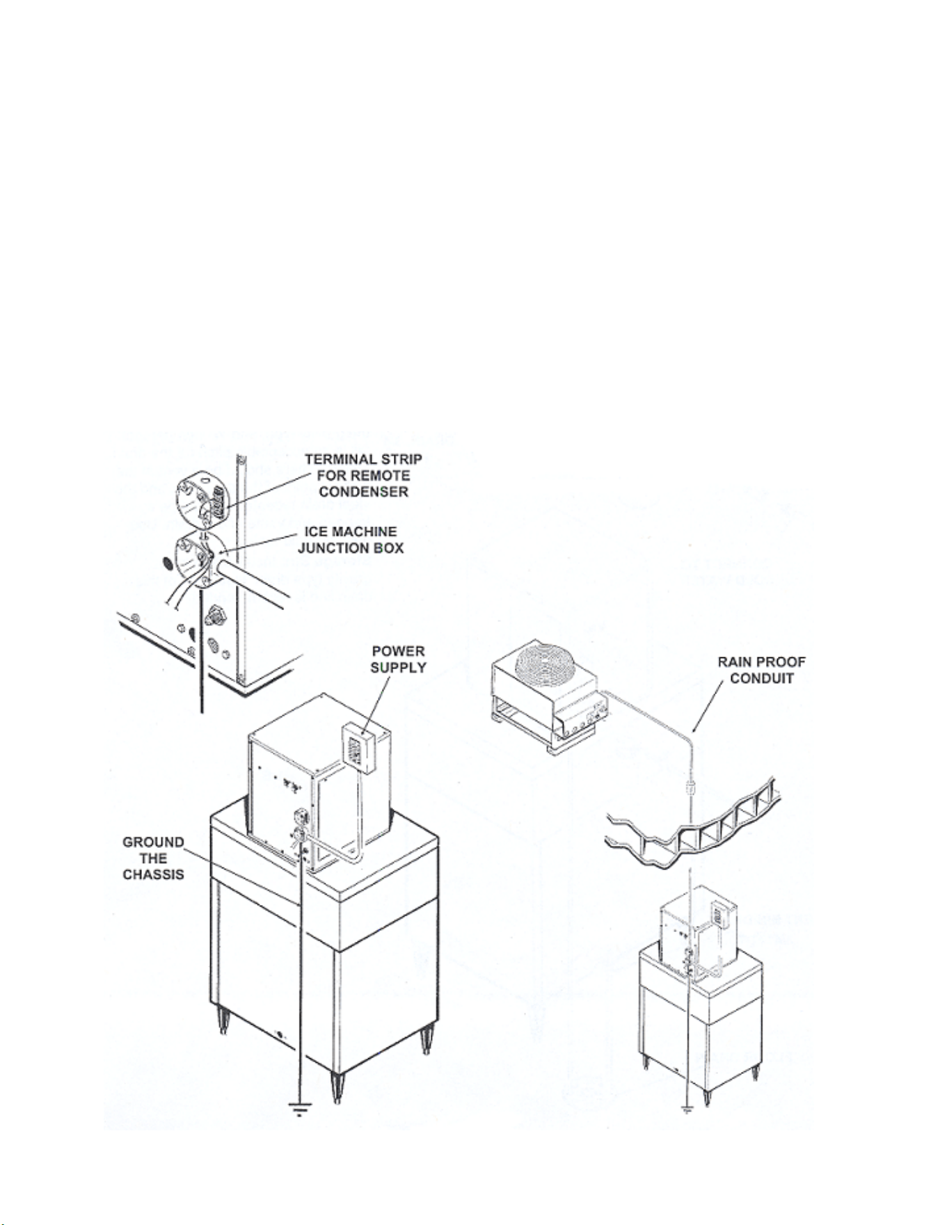
INSTALLATION MUST CONFORM TO ALL APPLICABLE CODES.
Connect the electrical power to the unit to the wires in the junction box at the rear of the machine. Check the
nameplate (located on the back panel) for the voltage requirements, and for the minimum circuit ampacity.
The machine requires a solid chassis to earth ground wire.
Connect the ice machine to its own electrical circuit so it is individually fused. Voltage variation must remain
within design limitations, even under starting conditions.
There is a separate junction box for the remote condenser fan motor. Install an interconnecting wire between
the remote condenser and the junction box at the back of the ice machine.
The remote condenser must be wired to the ice machine in accordance with local and national electrical codes
with a minimum of 18 AWG. wire with a ground bonding wire connected to the ground screw provided in both
the condenser and machine field wiring boxes. All outdoor wiring must be in rainproof conduit.
All external wiring must conform to national, state and local electrical codes. The use of a licensed
electrician is required to perform the electrical installation.
17
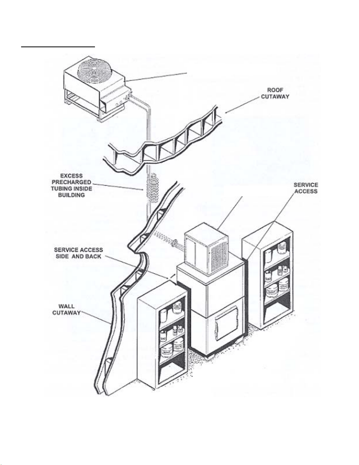
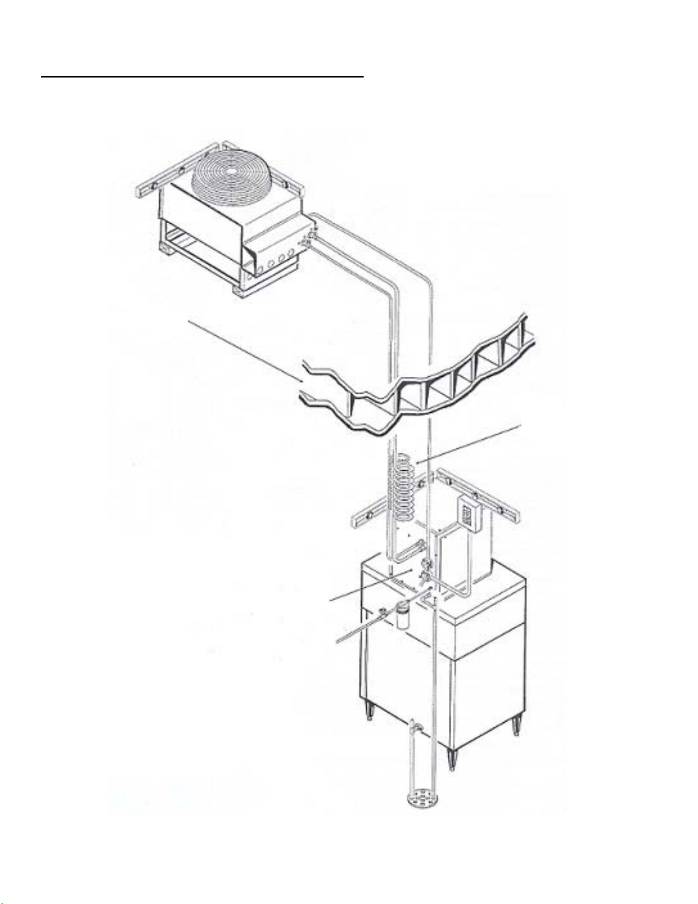
Completed Installation-Remote Condenser
Roof Cut-A-Way
Remote Line Set
Ice Machine
A typical installation should generally
appear as illustrated below. The
best place for the remote condenser
is above the ice machine, although
other locations are permissible.
18
For the Installer (Checklist)
Final Check List: Air and Water Cooled
_______1. Is the ice machine installed indoors in a location where the air and water temperatures are
controlled and where they do not exceed the design limitations?
_____2. Is there an electrical service disconnect within sight of the installed machine?
_____3. Has the voltage been checked and compared to the nameplate requirements?
_____4. Have all the plumbing connections been made and checked for leaks?
_____5. Is the ice machine and storage bin level?
_____6. Is there a minimum of 6 inches of clearance at the back of the machine for proper service
access and air circulation?
_____7. Is the water pressure a minimum of 20 psig?
_____8. Has the ice machine been secured to the bin?
_____9. Is there clearance over the top of the ice machine for service access?
____10. Is there a water shut off valve installed near the ice machine?
Note: Fasten the ice machine
to the bin with the hardware
supplied with the ice machine
Insure the machine is level
19
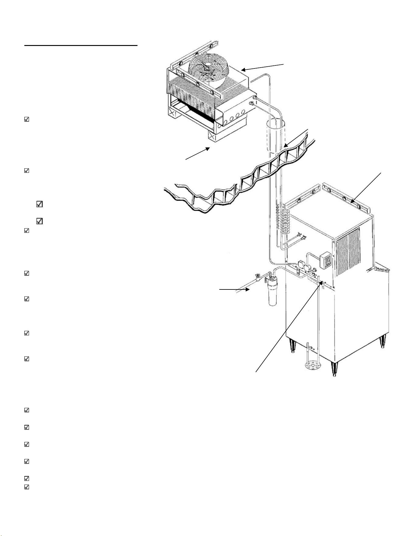
Final Check List: Remote
___1. Is the ice system installed
indoors in a location where air
and water temperatures are
controlled, and where they do
not exceed the design
limitations?
___2. Is there an electrical service
within sight of the installed
machine? Has the voltage
been checked, and compared
to nameplate requirements?
___3. Have all the plumbing
connections been made and
checked for leaks?
___4. Has the machine and
bin been leveled?
___5. Is there a minimum of 6 inches
clearance at the rear, left and
right of the machine for proper
service access?
___6. Is the water pressure a
minimum of 20 psig?
___7. Has the machine been
secured to the bin or
dispenser?
___8. Is there a water shut off valve
installed near the machine?
___9. Is the remote condenser
installed per local codes, and
in a place where it has
adequate ventilation and
minimal solar heat gain?
___10. Has all shipping material and literature (inside front panel) been removed from the units?
___11.Have the remote condenser and pre-charged lines been properly installed?
___12. Has the electrical connection between the ice maker and condenser been made?
___13. Verify that the master switch is in the OFF position.
___14. Switch ON the electrical power.
___15. Refer to the Pre-Start instructions
Remote condenser
secured?
Roof Holes Sealed?
Condenser Leveled?
Power Supply?
Plumbing?
Machine
Leveled?

20
Machine Startup
Pre-Start Inspection: Air and Water Cooled
1. Remove the front and side service panels.
2. Check that any shipping blocks have been removed.
3. Inspect the interior of the ice machine for loose screws or wires.
4. Check that no refrigerant lines are rubbing each other.
5. Check that the fan blades turn freely (Air Cooled).
6. Check that the unit is installed correctly according to the final check list.
Start Up
1. Go through the pre-start inspection.
2. Open the hand valve, observe that water enters the water reservoir, fills the tube from the water
reservoir to the evaporator and then shuts off. (Water cooled only, Turn the water supply ON to the
water cooled condenser). Check for leaks.
3. Switch the master (mode) switch ON. The electrical start up sequence in automatic.
a. There should be a short (15 second) delay before the gear motor starts.
b. After the gear motor starts, the compressor will start.
4. On air cooled models, the condenser will begin to discharge warm air, on water cooled models, the
water regulating valve will open and warm water will be discharged into the drain.
5. The unit should soon be making ice, if desired; the low side pressure may be checked: it should be 32
psig +/- 2 psig.
The suction line temperature at the compressor is normally very cold, nearly to the point of frost up to
the compressor body, but not on it.
The air cooled discharge pressure will depend upon air and water temperatures, but should be between
200 psig and 280 psig.
The water cooled discharge pressure should be a constant at about 245 psig.
Note: The above pressures are for new, clean machines. You can expect to see some values higher,
and some lower between different units.
6. There are no adjustments to make, so replace the panels.
7. Clean and/or sanitize the storage bin interior, wipe off the exterior with a clean, damp cloth.
8. Give the owner/user the service manual, instruct him/her in the operation of the unit, and make sure
they know who to call for service.
9. To view the warranty details, register products, or check your warranty status, visit the “Warranty
Registration” page at www.iceomatic.com/warranty

21
Pre-Start Inspection: Remote
1. Remove the front and side service panels.
2. Check that any shipping blocks have been removed.
3. Inspect the interior of the ice machine for loose screws or wires.
4. Check that no refrigerant lines are rubbing each other.
5. Check that the fan blades turn freely (Remote Condenser).
6. Check that the refrigerant lines are properly installed.
7. Check that the unit is installed correctly according to the final check list.
Start Up
1. Go through the pre-start inspection.
2. Open the hand valve, observe that water enters the water reservoir, fills the tube from the water
reservoir to the evaporator and then shuts off. (Water cooled only, Turn the water supply ON to the
water cooled condenser). Check for leaks.
3. Open the King Valve.
4. Switch the master switch ON. The electrical start up sequence in automatic.
a. There should be a short (15 second) delay before the gear motor starts and the liquid line
opens.
b. After the liquid line opens, the low pressure control will close and the compressor will start.
5. The remote condenser fan turns, and the condenser begins to discharge warm air.
6. The unit should soon be making ice, if desired; the low side pressure may be checked: it should be 32
psig +/- 2 psig.
a. The air cooled discharge pressure will depend upon air and water temperatures, but should be
between 200 psig and 280 psig.
7. There are no adjustments to make, so replace the panels.
8. Clean and/or sanitize the storage bin interior, wipe off the exterior with a clean, damp cloth.
9. Give the owner/user the service manual, instruct him/her in the operation of the unit, and make sure
they know who to call for service.
10. To view the warranty details, register products, or check your warranty status, visit the “Warranty
Registration” page at www.iceomatic.com/warranty

22
Cleaning
ICE Machine and/or Bin/Dispenser Cleaning and Sanitizing Instructions
Cleaning should be scheduled at a minimum of twice per year.
Sanitizing should be performed after each cleaning or more frequently as required.
Note: Electrical power will be ON when performing the following cleaning instructions.
Caution: Eye protection is recommended when handling descaler or sanitizer.
Wear protective rubber gloves when handling descaler or sanitizer.
The cleaning and sanitizing of any commercial ice machine are important procedures all operators need to
have in their preventive maintenance protocol. While similar, these two procedures are uniquely different and
accomplish different things. Cleaning or de-liming, dissolves the mineral deposits on the evaporator and
removes scale, calcium and other chemical buildup. Sanitizing disinfects the machine and removes microbial
growth including mold and slime.
In either case, it is important to use solutions that do not harm the ice machine. Never use cleaning or
sanitizing solutions that contain Nitric Acid, Sulfuric Acid, Hydrochloric Acid, Carbolic Acid, Acetic Acid, diluted
Acetic Acid or non-food-grade vinegar (concentration of acetic acid greater than 6% and does not contain
enzymes created in processing) or any chlorine-based solution such as bleach, chlorine dioxide or any type of
salts such as potassium chloride (potassium salts) or sodium chloride. Check the label or the manufacturer’s
Material Safety Data Sheet (MSDS) to be sure. These chemicals can attack the surface of the evaporator as
well as other metal components causing corrosion and flaking. Reverse Osmosis (RO) water can be very
acidic and can attack the evaporator and other metal in the ice machine. Because the RO process removes all
minerals and metals from the water it can promote the faster growth of microbial, mold and slime. If RO water
is used, Ice-O-Matic® recommends the water pH is verified to be a neutral 7.0 to minimize the corrosive
effects. Incorrect cleaners, sanitizers, and RO water that does not have a neutral pH could void the machine’s
warranty.
Cleaning/Descaling
Prior to Cleaning the ice machine and/or Bin/Dispenser, perform the following:
1. Remove the ice machine front panel.
2. Turn the machine “OFF” at the ON/OFF selector switch.
3. Remove all ice in the storage bin. (Required for cleaning and/or sanitizing)
Cleaning Instructions-Ice Machine
1. Remove the cover from the water reservoir and block up the float.
2. Drain the water reservoir and freezer assembly using the drain tube attached to the freezer water inlet.
Return the drain tube to its normal position and replace the end cap.
3. Add recommended amount of ice machine cleaner (diluted per manufacturer’s instructions) to the water
trough. (Reference cleaner Manufacturer’s instructions on the package)
4. Slowly pour the cleaning solution into the water reservoir until full. Wait 15 minutes, then switch the
ON/OFF switch to the ON position.
5. As the ice machine begins to use water from the reservoir, continue to add more cleaning solution to
maintain a full reservoir.
6. After all of the cleaning solution has been added to the reservoir, and the reservoir is nearly empty, switch
the ON/OFF switch to the OFF position.
7. Drain the water reservoir and freezing assembly using the drain tube attached to the to the freezer water
inlet. Return the drain tube to its normal position and replace the drain plug end cap. Wash and rinse the
water reservoir.
8. Sanitizing the Ice Machine is required after cleaning per Sanitizing Instructions

23
Cleaning Instructions-Storage Bin/ Dispenser
1. Open the bin door and remove all of the ice in the storage bin, store the ice in a clean container for reuse or
discard.
2. Add recommended amount of ice machine cleaner (diluted per manufacturer’s instructions) (Reference
cleaner Manufacturer’s instructions on the package)
3. Thoroughly wash all surfaces within the bin, this includes the bin door, bin walls, window track and snout
area with cleaner and water. Note: An extended handle soft bristle brush may be required.
4. Allow the mineral deposits to absorb the cleaner for approximately 15 minutes to remove and loosen the
mineral deposits. Note: This includes the bin drain.
5. Rinse thoroughly with water. Note: Repeat Steps 3, 4 and 5 as required.
6. Sanitizing the Storage Bin/Dispenser is required after cleaning per Sanitizing Instructions

24
Sanitizing
Prior to Sanitizing the ice machine and/or Bin/Dispenser, perform the following:
1. Remove the ice machine front panel and top panel.
2. Turn the machine “OFF” at the ON/OFF selector switch.
3. Remove all ice in the storage bin. (Required for cleaning and/or sanitizing)
Sanitizing Instructions-Ice Machine
1. Use an EPA approved food equipment sanitizer at the solution mix recommended by the sanitizer
manufacturer.
2. Slowly pour the sanitizer solution into the water reservoir until full. Wait 15 minutes, then switch the ON/OFF
switch to the ON position.
3. As the ice machine begins to use water from the reservoir, continue to add more sanitizing solution to
maintain a full reservoir.
4. After all of the sanitizing solution has been added to the reservoir, and the reservoir is nearly empty, switch
the ON/OFF switch to the “OFF” position.
5. Drain the water reservoir and freezing assembly using the drain tube attached to the to the freezer water
inlet. Return the drain tube to its normal position and replace the drain plug end cap. Wash and rinse the
water reservoir. During this time, wipe down all other ice machine splash areas. Inspect to insure that water
transport system components are in the correct position.
6. Place the ON/OFF switch to the “ON” position and replace the front panel.
7. Continue ice making for at least 15 minutes to flush out any cleaning or sanitizing solution.
8. Remove and discard all ice in the storage bin. DO NOT USE any ice produced from the cleaning
solution.
Sanitizing Instructions- Bin/ Dispenser
1. Use an EPA approved food equipment sanitizer at the solution mix recommended by the sanitizer
manufacturer.
2. Sanitize the bin interior, this includes the bin door, bin walls, window track and snout area with an approved
sanitizer using the directions for that sanitizer. Note: This includes the bin drain.
3. Remove and discard all ice in the storage bin. DO NOT USE any ice produced from the cleaning
solution.
25
Condenser Cleaning
The condenser may appear to be clean on the
surface, but it can still be clogged internally.
Check with a flashlight from the front to see if
light can be seen through the condenser fins.
The condenser coil must be kept clean. The
condenser can be cleaned with compressed air
or by using a brush with soft bristles..
If a brush is used, brush in the direction of the
fins taking care not to bend or distort the fins.
If the condenser fins are bent or distorted, this will restrict the airflow through the condenser and the fins will
need to be straightened with a fin comb.
When cleaning the Condenser, check the fan blade for cleanliness and for balance. Balance is checked by
spinning the blade by hand and looking for any wobble. Pull on the shaft in several directions to check the
bearings of the motor.
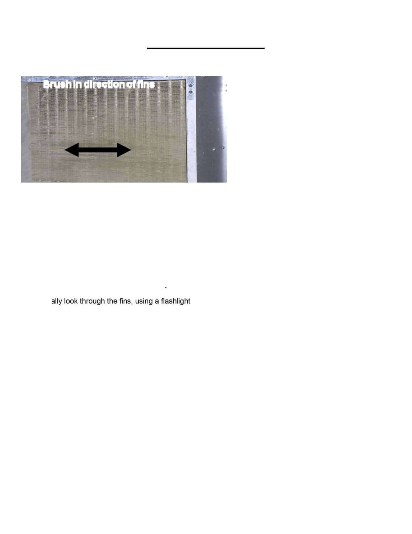
The fins of the remote condenser require periodic cleaning.
At 6 month intervals the fins on the inlet side of the condenser (bottom as shown) should be brushed free of
dust and dirt
Brush in the direction of the fins as noted by the arrows.
Additionally look through the fins, using a flashlight if required, to insure there is no other blockage obstructing
air flow between the fins.
If the air flow appears to be blocked, blow out the condenser using compressed air.
Caution: Disconnect electrical power before servicing this equipment.
Caution: Protective eye wear and gloves should be worn when cleaning the condenser.
26
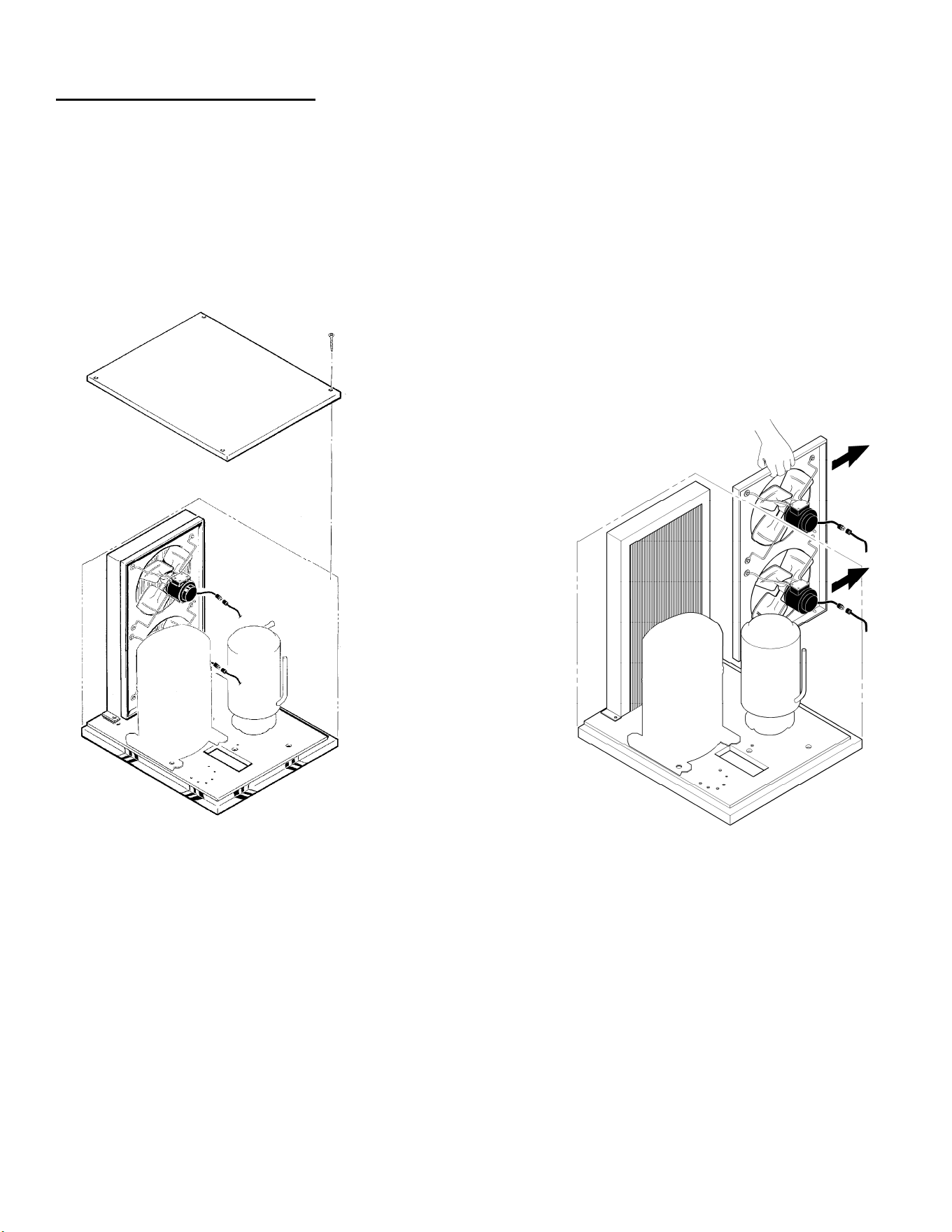
Clean the air cooled condenser:
Air flow on this model is from front to back, so the inside of the ice machine will have to be available to clean
the air cooled condenser. Use a vacuum cleaner or coil cleaner if needed. DO NOT use a wire brush.
● Disconnect electrical power, and remove the air filter if applicable. The filter may be cleaned or replaced.
● Clean the condenser: the condenser may appear to be clean on the surface, but it can still be clogged
internally. Check with a flashlight from the front to see if light can be seen through the condenser fins.
GEM0956 (For Reference)
Step 1. Remove the Top Panel
Step 2. Remove two screws
and unplug fan motors.
Step 3. Pull fan motor assembly
up and to the right to
remove.

27
Service History
What to Do Before Calling for Service
●Check the water supply to the ice machine. The ice machine is designed to shut off if there is no water to it.
Check the water filters if there are any.
●Check the power supply to the ice machine. Reset the breaker if it is tripped.
●If both water and power have been checked and are available, try switching the power OFF and then ON.
After 2 minutes the machine should restart. If this procedure restarts the machine, service should be called the
next time the machine stops.
Model Number:___________________ Serial Number:____________________ Install Date:____________
________________________________________________________________________________________
________________________________________________________________________________________
________________________________________________________________________________________
________________________________________________________________________________________
________________________________________________________________________________________
________________________________________________________________________________________
________________________________________________________________________________________
________________________________________________________________________________________
________________________________________________________________________________________
________________________________________________________________________________________
________________________________________________________________________________________
________________________________________________________________________________________
________________________________________________________________________________________
________________________________________________________________________________________
________________________________________________________________________________________
________________________________________________________________________________________
________________________________________________________________________________________
________________________________________________________________________________________
________________________________________________________________________________________
________________________________________________________________________________________
________________________________________________________________________________________
________________________________________________________________________________________
________________________________________________________________________________________
________________________________________________________________________________________
________________________________________________________________________________________
________________________________________________________________________________________
________________________________________________________________________________________
________________________________________________________________________________________
________________________________________________________________________________________
________________________________________________________________________________________
________________________________________________________________________________________
________________________________________________________________________________________
________________________________________________________________________________________
________________________________________________________________________________________
________________________________________________________________________________________
________________________________________________________________________________________
________________________________________________________________________________________
________________________________________________________________________________________