1
MS8239T/MS8239D+
Digital Multimeter User
Manual
Overview of Product Functions
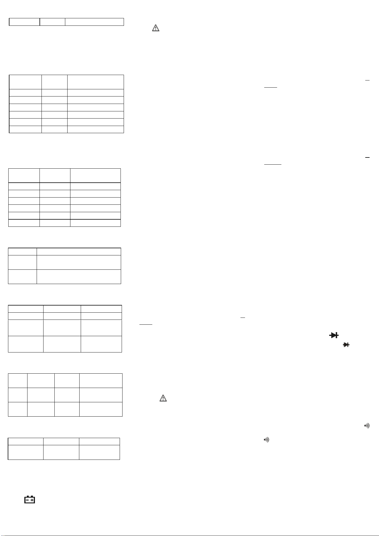
Model
Features
MS8239D+
MS8239T
Maximum
Display
4000
4000
DC Voltage
0.01mV–600V
0.01mV–600V
AC Voltage
0.01mV–600V
0.01mV–600V
DC Current
0.1uA–10A
0.1uA–10A
AC Current
0.1uA–10A
0.1uA–10A
Resistance
0.1Ω–40MΩ
0.1Ω–40MΩ
Capacitance
10pF–40mF
10pF–40mF
Frequency
1Hz–10MHz
1Hz–10MHz
℃
━
-20℃ to 750℃
℉
━
-4℉ to 1382℉
✓
✓
✓
✓
True RMS
✓
✓
Backlight
✓
✓
NCV
✓
✓
Live Wire
Identification
✓
✓
Data Hold
✓
✓
MIN/MAX
✓
✓
Relative
Value
Measuremen
t
✓
✓
Unit Display
✓
✓
Auto Power
Off
✓
✓
Range Mode
Automatic
Range
Automatic
Range
Power
Supply
1.5V×2
1.5V×2
Introduction
This product is a small handheld digital
multimeter offering stable performance, high
reliability, and anti-drop capabilities. The circuit
design centers around a large-scale dual-slope
integrating A/D converter with overload
protection, making this a superior and compact
measurement tool.
The instrument can measure AC/DC
voltage, AC/DC current, resistance, diodes,
circuit continuity, temperature, frequency, and
capacitance. It also functions as a live wire
detector, non-contact voltage (NCV) tester, and
unit symbol display.
The device is equipped with a backlight
for reading measurements in dark environments.
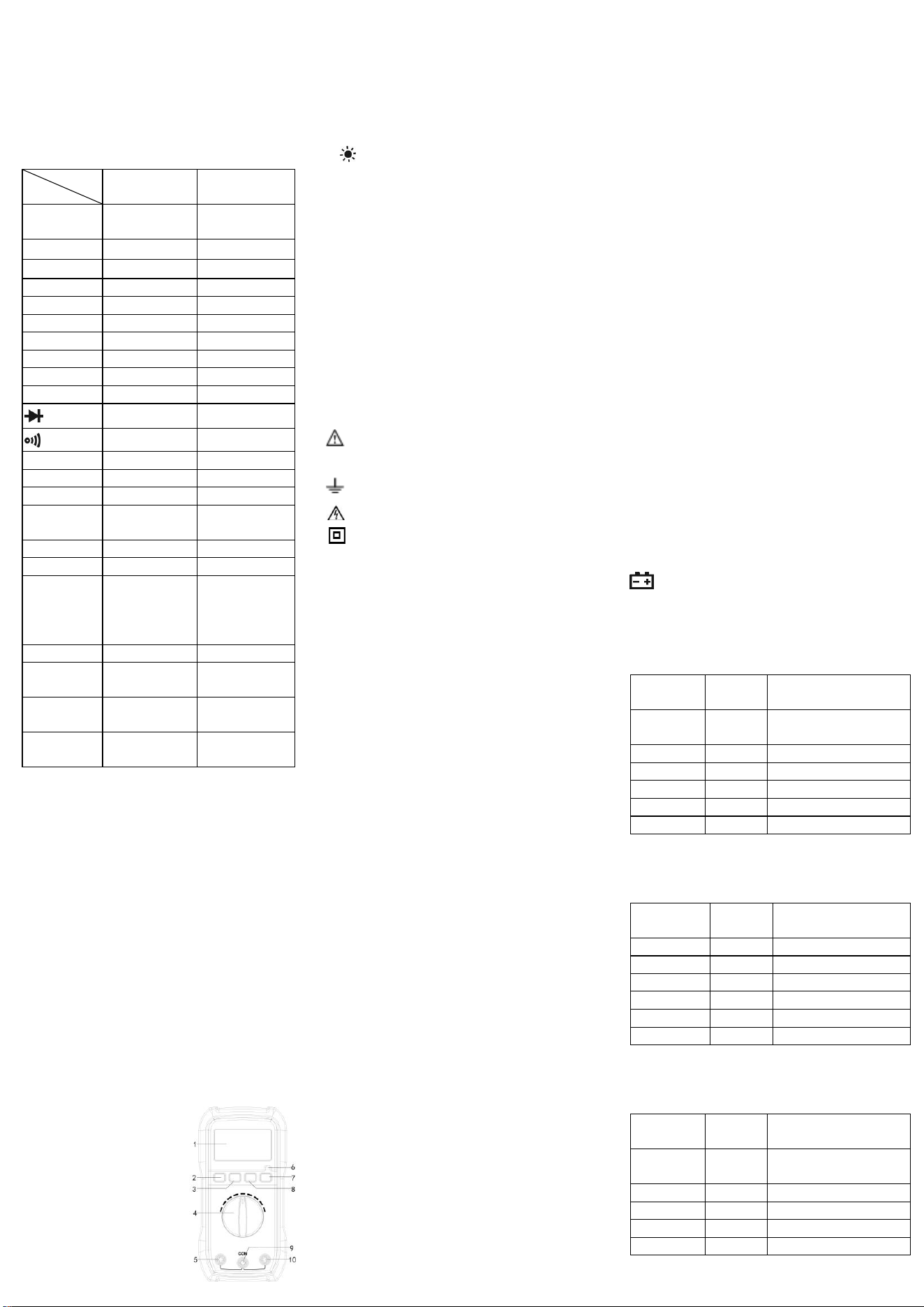
Panel Diagram
1. Display: LCD screen with 20 mm
character height
2. SEL Button: This button
is used to switch between
two or more functions
within the same range,
such as AC/DC voltage,
AC/DC current, diode,
continuity, and resistance;
℉ and ℃; NCV and live
wire identification.
3.MAX/MIN Button
4. Function Selector Dial
5.10A Jack
6.NCV Indicator Light
7.H Button (Data Hold)
(Backlight Button): Hold down the button
to turn on the backlight, down the button
again to turn off the backlight.
8.REL Button (Relative Value Measurement)
9.COM Jack
10. VΩmA Jack
Safety Information
This series of digital multimeters has been
designed in accordance with IEC1010 600V
(CAT III) and Pollution Degree 2 standards.
Please read this user manual thoroughly to
ensure safe instrument use and measurement
accuracy.
Safety Symbols
Important safety symbol; refer to the
manual
Grounding symbol
High voltage symbol
Double insulation symbol (Class II safety
equipment)
Operation Precautions
⚫ To comply with safety standards, the
instrument must be used with the provided
test leads only. If the test leads are
damaged, they must be replaced with the
same model or with leads that have the
same electrical specifications.
⚫ Do not exceed the input limit specified for
each range.
⚫ Avoid touching unused input terminals
during measurement.
⚫ When the range of the value to be
measured is unknown, set the
function/range dial to the highest range.
⚫ Before adjusting the function/range dial,
ensure that the test leads are disconnected
from the circuit being tested.
⚫ Before measuring resistance in a live
circuit, ensure that all power sources are
turned off and all capacitors are fully
discharged.
⚫ Be cautious when measuring voltages
above 60V DC or 30V AC. Do not touch
the parts of the test leads beyond the
finger guards.
⚫ When measuring televisions or
switch-mode power supplies, be aware
that pulses in the circuit may damage the
instrument.
⚫ Before testing transistors, ensure that the
test leads are not connected to any circuit.
⚫ Before using the test leads to measure
voltage, ensure that no electronic
components are connected to the transistor
test socket.
Maintenance
⚫ Disconnect the test leads from the circuit
before opening the back cover.
⚫ To protect the instrument’s internal
circuitry, always replace the fuse with one
of the same specifications.
⚫ Do not use the instrument if the back
cover is not securely closed, or if the
screws are not tightened.
⚫ Clean the instrument with a damp cloth
and a small amount of detergent only. Do
not use chemical solvents on the casing.
⚫ If any abnormalities are observed,
immediately discontinue use and send the
instrument for repairs.
Technical Specifications
Accuracy: ±(percent of reading + number of
counts), valid for 1 year
Environmental Temperature: 18°C to 28°C;
Environment Humidity: ≤80%
General Specifications:
● Maximum Voltage between Input and Ground:
CAT III 600V
● Fuse: F500mA/500V, F10A/500V
● Power Supply: 1.5V AAA ×2
● Maximum Display Value: 4000
● Overload Indicator: “1” or “OL”
● Polarity Display: Negative polarity is
displayed as “-”
● Working Temperature: 0°C to 40°C
● Storage Temperature: -10°C to 50°C
● Low Voltage Indicator: The display shows
● Dimensions: 147 mm × 74 mm × 46 mm
● Weight: Approximately 229 g (including
batteries)
DC Voltage
Range
Resolut
ion
Accuracy
40.00mV
0.01m
V
±(0.5%+5)
400.0mV
0.1mV
±(0.5%+3)
4.000V
0.001V
±(0.8%+3)
40.00V
0.01V
±(0.8%+3)
400.0V
0.1V
±(0.8%+3)
600V
1V
±(1.0%+5)
Overload protection: mV range: 250V DC or
AC RMS; all other ranges: 600V DC or AC
RMS
DC Current
Range
Resolut
ion
Accuracy
400.0A
0.1A
±(1.0%+5)
4000A
1A
±(1.0%+5)
40.00mA
0.01mA
±(1.0%+5)
400.0mA
0.1mA
±(2.0%+5)
4.000A
0.001A
±(2.5%+5)
10.00A
0.01A
±(2.5%+5)
Overload protection: F500mA/500V,
F10A/500V fuse
AC Voltage
Range
Resolut
ion
Accuracy
40.00mV
0.01m
V
±(1.0%+20)
400.0mV
0.1mV
±(1.0%+10)
4.000V
0.001V
±(0.8%+3)
40.00V
0.01V
±(0.8%+3)
400.0V
0.1V
±(0.8%+3)
2
600V
1V
±(1.2%+5)
Overload protection: mV range: 250V DC or
AC RMS; all other ranges: 600V DC or AC
RMS
Frequency range: 40Hz to 1000Hz
Display: True RMS
AC Current
Range
Resolut
ion
Accuracy
400.0A
0.1A
±(1.8%+3)
4000A
1A
±(1.5%+5)
40.00mA
0.01mA
±(1.5%+5)
400.0mA
0.1mA
±(2.5%+5)
4.000A
0.001A
±(3.0%+10)
10.00A
0.01A
±(3.0%+10)
Overload protection: F500mA/500V,
F10A/500V fuse
Frequency range: 40Hz to 1000Hz
Resistance
Range
Resolutio
n
Accuracy
400.0Ω
0.1Ω
±(1.2%+2)
4.000kΩ
0.001kΩ
±(1.0%+2)
40.00KΩ
0.01kΩ
±(1.0%+2)
400.0KΩ
0.1kΩ
±(1.0%+2)
4.000MΩ
0.001MΩ
±(1.0%+2)
40.00MΩ
0.01MΩ
±(1.2%+8)
Overload protection: 250V DC or AC RMS
Diode and Continuity Test
Range
Description
Buzzer
If resistance is less than
50Ω±30Ω, the buzzer will sound.
Diode
The approximate forward voltage
drop is displayed.
Overload protection: 250V DC or AC RMS
Capacitance
Range
Resolution
Accuracy
40.00nF
10pF
±(4.0%+25)
400.0nF~
400.0uF
100pF~
100nF
±(4.0%+15)
4.000mF~
40.00mF
1uF~
10uF
±(5.0%+25)
Overload protection: 250V DC or AC RMS
Temperature Test
Func
tion
Range
Resolut
ion
Accuracy
℃
-20℃~
750℃
1℃
±(2.0%+3℃)
℉
-4℉~
1382℉
1℉
±(3.0%+3℉)
Overload protection: 250V DC or AC RMS
Frequency
Range
Resolution
Accuracy
4.000Hz~
10.00MHz
0.001Hz~
0.01MHz
±(0.1%+2)
Overload protection: 250V DC or AC RMS
Operating Instructions
Precautions before Operation:
1. Power on the instrument and check if it has
sufficient battery. If the battery voltage is low,
the symbol will appear on the display,
indicating that the battery needs to be
replaced before use.
2. The symbol next to the test lead input
jack indicates that the input voltage or current
must not exceed the specified value to protect
the internal circuitry from damage.
3 . Before testing, the function/range dial
should be set to the desired range.
Measuring DC Voltage
1. Insert the red test lead into the VΩmA jack.
Insert the black test lead into the COM jack.
2. Turn the function dial to the V or mV range,
press the SEL button to switch to DC
voltage mode, and connect the test leads to
the power source or load to be tested. The
polarity of the terminal connected to the red
test lead will be displayed on the screen.
Note:
⚫ For manual range instruments, if the
voltage to be measured is unknown, set
the function dial to the highest range and
gradually lower it until satisfactory
resolution is obtained.
⚫ If the display shows “1” or “OL”, it
indicates an overload, and the function
dial must be set to a higher range.
⚫ Do not input voltage higher than 600V.
Although higher voltages may be
displayed, there is a risk of damaging the
internal circuitry.
⚫ Be especially careful to avoid electric
shock when measuring high voltages.
Measuring DC Current
1. Insert the black test lead into the COM jack.
If the current to be measured is less than
400mA, insert the red test lead into the
VΩmA jack. If the current is between 400mA
and 10A, insert the red test lead into the 10A
jack.
2. Set the function dial to the desired current
range, press the SEL button to switch to DC
current mode, and connect the test leads in
series with the load. The current value will be
displayed, along with the polarity of the
connection for the red test lead.
Note:
⚫ If the current range to be measured is
unknown, set the function dial to the
highest range and gradually reduce it until
satisfactory resolution is achieved.
⚫ If the display shows only “1” or “OL”, it
indicates an overload, and the function
dial must be set to a higher range.
⚫ The symbol next to the test lead
jacks indicates a maximum input current
of either 400mA or 10A, depending on the
jack being used. Excessive current will
blow the fuse.
Measuring AC Voltage
1. Insert the red test lead into the VΩmA jack.
Insert the black test lead into the COM jack.
2. Turn the function dial to the V or mV range,
press the SEL button to switch to AC voltage
mode, and connect the test leads to the power
source or load being tested.
Note: Refer to the precautions for DC voltage
measurement.
Measuring AC Current
1. Insert the black test lead into the COM jack.
If the current to be measured is less than
400mA, insert the red test lead into the
VΩmA jack. If the current is between 400mA
and 10A, insert the red test lead into the 10A
jack.
2. Set the function dial to the desired current
range, press the SEL button to switch to AC
current mode, and connect the test leads in
series with the load. The current value will be
displayed on the screen.
Note: Refer to the precautions for DC current
measurement.
Measuring Resistance
1. Insert the black test lead into the COM jack.
Insert the red test lead into the VΩmA jack.
2. Set the function dial to the desired Ω range,
press the SEL button to switch to Ω
(resistance) mode, connect the test leads in
parallel with the resistor being measured, and
read the measurement result from the display.
Note:
⚫ For manual range meters, if the measured
resistance exceeds the maximum value of
the selected range, the display will show
“1” or “OL”. In this case, select a higher
range. When measuring resistances above
1MΩ, it may take a few seconds for the
reading to stabilize. This is normal for
high-resistance measurements.
⚫ When there is no input, e.g., when there is
an open circuit, the instrument will
display “1” or “OL”.
⚫ Before measuring resistance in a live
circuit, ensure that all power sources are
turned off and all capacitors are fully
discharged.
Measuring Diodes
1. Insert the black test lead into the COM jack.
Insert the red test lead into the VΩmA jack.
2. At this point, the red test lead will have a
positive (+) polarity.
3. Set the function dial to the position and
press the SEL button to select (diode)
measurement mode. Connect the red test lead
to the anode of the diode and the black test
lead to the cathode. The display will show the
approximate forward voltage drop of the
diode.
Continuity Test
1. Insert the black test lead into the COM jack
and the red test lead into the VΩmA jack.
2. Set the function dial to the continuity
position and press the SEL button to select
(continuity) measurement mode. Connect
the test leads to two points of the circuit
being tested. If the resistance between the
two points is less than approximately 50Ω ±
30Ω, the built-in buzzer will sound,
indicating continuity between those points.
Capacitance Measurement
1. Insert the black test lead into the COM
jack and the red test lead into the VΩ
jack.
2. Turn the function dial to the capacitance

3
range and discharge the capacitor being
tested.
3. Connect the black test lead to the negative
terminal of the capacitor and the red test
lead to the positive terminal.
4. Read the capacitance value from the LCD.
5. When measuring small capacitors, the
meter may show a small non-zero value
due to environmental factors and
interference from the test leads. Subtract
the currently displayed value during
testing.
Note:
⚫ Before measuring resistance in a live
circuit, ensure that all power sources are
turned off and all capacitors are fully
discharged.
⚫ Do not input any voltage while in the
capacitance range to avoid damaging the
meter.
Frequency Measurement
1. Insert the black test lead into the COM
jack. Insert the red test lead into the VΩ
jack.
2. Turn the function dial to the frequency
range.
3. Use the test leads to measure the
frequency of the circuit being tested
(connect the test leads in parallel with the
circuit).
4. Read the measured frequency value from
the LCD.
Note: When conducting measurements in a
live circuit, ensure that the input voltage does
not exceed AC 250V.
Temperature Measurement
1. Turn the function selector dial to the ℃/℉
position.
2. Insert the red end of the temperature probe
into the VΩmA jack and the black end into
the COM jack.
3. Place the testing end of the temperature probe
into the temperature field to be measured.
4. Wait a few minutes for the temperature to
stabilize, then read the measured
temperature value on the display.
5. Press the SEL button to switch between ℃
and ℉.
Non-Contact Voltage Detection (NCV)
1. Turn the function dial to the NCV range
and press the SEL button to switch to the
Non-Contact AC Voltage Detection (NCV)
mode. The display will show “EF”.
2. Move the NCV detection area at the top of
the instrument close to the live object. If
the instrument detects a live conductor, the
NCV indicator light will flash, and the
buzzer will emit a “beep-beep-beep” alarm
sound, alerting the user to the presence of
voltage and the need to ensure safe
operation.
Note:
⚫ Even if there is no indication, voltage may
still be present. Do not rely solely on the
non-contact voltage detector to determine
whether a conductor is live.
⚫ Detection results may be affected by
factors such as socket design, insulation
thickness, and material type.
⚫ External sources of interference (e.g.,
flashlights, motors, etc.) may affect the
instrument, causing inaccurate detection.
Live Wire Identification (LIVE)
1. Turn the function dial to the LIVE range and
press the SEL button to switch to the Live
Wire Identification (LIVE) mode. The
display will show “LIVE”.
2. Insert the red test lead into the VΩmA jack
and use the tip of the test lead to touch the AC
voltage. When the instrument emits a
“beep-beep-beep” alarm sound and the red
LED indicator light turns on, the wire being
touched is the live wire.
Note: If the circuit has severe leakage
(approximately ≥15V), the instrument may
give both audible and visual warnings when
the red test lead touches the neutral wire.
Replacing the Battery and Fuse
1. Under normal circumstances, the fuse does
not need to be replaced. Power off the
instrument and remove the test leads before
proceeding with fuse or battery replacement.
Unscrew the screws on the back cover to
open the case.
2. The fuse specifications for this instrument are:
500mA/500V and F10A/500V fast-blow type.
The replacement fuse must be of the same
specification.
3. Use the same type of battery when replacing
the battery.
4. After replacing the battery or fuse, the back
cover must be securely tightened before using
the instrument.
Warning
1. To avoid electric shock, ensure that the test
leads are disconnected from the
measurement circuit before opening the
back cover.
2. Before using the instrument, ensure that the
back cover is securely fastened.
Accessories
●User manual: ×1
●Test leads: ×1 set
●Carrying case: ×1
●Battery: 9V or 1.5V
●Temperature probe: ×1 (MS8239T)