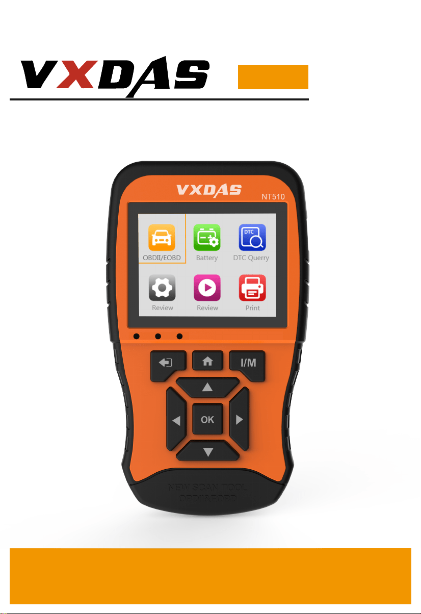
NT510
OBD2 & EOBD Scan Tool
User's Manual

1. Safety Precautions and Warnings 1
2. General Introduction 1
2.1 On-Board Diagnostics(OBD)II 1
2.2 Diagnostic Trouble Codes (DTCs) 2
2.3 Location of the Data Link Connector (DLC) 4
2.4 OBD II Readiness Monitors 4
2.5 OBD II Monitor Readiness Status 6
2.6 OBD II Definitions 7
2.7 OBD II Diagnostic Test Modes 8
3. Product Instructions 9
3.1 Tool Description 9
3.2 Specifications 10
3.3 Accessories Included 11
3.4 Keyboard 11
3.5 Power 11
3.6 System Setup 12
3.7 Vehicle Coverage 13
3.8 Product Troubleshooting 14
4. OBDII Diagnosis 15
4.1 Read DTC 16
4.2 DTC Query 17
4.3 Live Data 18
4.4 Freeze Frame 21
4.5 I/M Readiness 22
4.6 Smog Check 24
4.7 MIL Status 24
4.8 O2 Sensor 25
CONTENTS

4.9 Mode 6 26
4.10 Mode 8 27
4.11 Viewing Vehicle Information 28
4.12 Fuel Analysis 28
4.13 Core Analysis 29
4.14 Engine Analysis 29
4.15 Battery Test 30
4.16 DTC Query 30
5. Review and Print Data 31
5.1 Reviewing Data 31
5.2 Printing Data 32
6.Update and Warranty 33
6.1 Software Update 33
6.2 Limited One Year Warranty 33
6.3 Service Procedures 34

1. Safety Precautions and Warnings
To prevent personal injury or damage to vehicles and/or
the scan tool, read this instruction manual first and
observe the following safety precautions at a minimum
whenever working on a vehicle:
2.General Introduction
2.1 On-Board Diagnostics(OBD)II
The first generation of On-Board Diagnostics(called
OBD I)was developed by the California Air Resources
Board (ARB) and implemented in 1988
to monitor
Always perform automotive testing in a safe environment.
Wear safety eye protection that meets ANSI standards.
Keep clothing, hair, hands, tools, test equipment, etc. away
from all moving or hot engine parts.
Operate the vehicle in a well ventilated work area: Exhaust
gases are poisonous.
Put blocks in front of the drive wheels and never leave the
vehicle unattended while running tests.
Use extreme caution when working around the ignition coil,
distributor cap, ignition wires and spark plugs. These com-
ponents create hazardous voltages when the engine is
running.
Put the transmission in PARK (for automatic transmission)or
NEUTRAL (for manual transmission) and make sure the
parking brake is engaged.
Keep a fire extinguisher suitable for gasoline/chemical/
electrical fires nearby.
Don't connect or disconnect any test equipment while the
ignition is on or the engine is running.
Keep the scan tool dry, clean, free from oil/ water or grease.
Use a mild detergent on a clean cloth to clean the outside of
the scan tool when necessary.
1

2.2 Diagnostic Trouble Codes (DTCs)
OBD II Diagnostic Trouble Codes are codes that are
stored by the on-board computer diagnostic system in
response to a problem found in the vehicle. These
codes identify a particular problem area and are intend-
ed to provide you with a guide as to where a fault might
be occurring within a vehicle.
There are three types of DTCs:
some of the emission control components on vehicles.
As technology evolved and the desire to improve the
On-Board Diagnostic system increased, a new genera-
tion of On-Board Diagnostic system was developed.
This second generation of On-Board Diagnostic regula-
tions is called "OBDII".
The OBD II system is designed to monitor emission
control systems and key engine components by per-
forming either continuous or periodic tests of specific
components and vehicle conditions. When a problem is
detected, the OBD II system turns on a warning lamp
(MIL) on the vehicle instrument panel to alert the driver
typically by the phrase of "Check Engine" or "Service
Engine Soon". The system will also store important
information about the detected malfunction so that a
technician can accurately find and fix the problem. Here
below follow three pieces of such valuable information:
1) Whether the Malfunction Indicator Light (MIL)is
commanded ‘on’ or ‘off’;
2) Which, if any, Diagnostic Trouble Codes (DTCs) are
stored
3) Readiness Monitor status.
2

OBD II Diagnostic Trouble Codes consists of a five-digit
alphanumeric code. The first character, a letter, identi-
fies which control system sets the code. The other four
characters, all numbers, provide additional information
on where the DTC originated and the operating condi-
tions that caused it to set. Here below is an example to
illustrate the structure of the digits:
DTC Example
P 0 2 0 2
P--Systems: B=Body C= Chassis P=Powertrain U=-
Network
0--Code Type Generic(SAE): P0, P2, P34-P39; B0, B3;
C0, C3; U0, U3 Manufacturer Specific: P1, P30-P33;
B1, B2; C1, C2; U1, U2
2--Sub-systems: 1=Fuel and Air Metering 2=Fuel and
Air Metering 3=Ignition System or Engine Misfire
4=Auxiliary Emission Controls 5=Vehicle Speed Control
and Idle Controls 6=Computer Output Circuits
7=Transmission Controls 8=Transmission Controls
02--Identifying specific malfunction section of the
systems
1. Pending - When a fault condition is identified during a Drive
Cycle, but does not meet enough criteria to activate the MIL.
If the fault condition occurs during two consecutive Drive Cycles, it
will turn into a Stored DTC and the MIL will activate.
2.
Stored-A DTC is stored when a fault condition has occurred
that meets enough criteria to activate the MIL.
3.
Permanent-A stored DTC that can only be cleared by the
OBDII system,after repairs are made,and a set number of Driving
Cycles have been completed.
3

2.3 Location of the Data Link Connector (DLC)
The DLC (Data Link Connector or Diagnostic Link Con-
nector) is the standardized 16-cavity connector where
diagnostic scan tools Interface with the vehicle's
on-board computer. The DLC is usually located 12
inches from the center of the instrument panel (dash),
under or around the driver's side for most vehicles. If
Data Link Connector is not located under dashboard. a
label should be there telling location. For some Asian
and European vehicles, the DLC is located behind the
ashtray and the ashtray must be removed to access the
connector. If the DLC cannot be found, refer to the
vehicle's service manual for the location.
2.4 OBD II Readiness Monitors
An important part of a vehicle's OBD II system is the
Readiness Monitors, which are indicators used to find
out if all of the emissions components have been evalu-
ated by the OBD II system. They are running periodic
tests on specific systems and components to ensure
that they are performing within allowable limits.
Currently, there are eleven OBD II Readiness Moni-
tors(or I/M Monitors) defined by the U.S. Environmental
Protection Agency(EPA). Not all monitors are supported
by all vehicles and the exact number of monitors in any
vehicle depends on the motor vehicle manufacturer's
emissions control strategy.
Continuous Monitors--Some of the vehicle components
or systems are continuously tested by the vehicles OBD
II system, while others are tested only under specific
4

vehicle operating conditions. The continuously moni-
tored components listed below are always ready:
1) Misfire
2) Fuel System
3) Comprehensive Components(CCM)
Once the vehicle is running, the OBD II system is con-
tinuously checking the above components, monitoring
key engine sensors, watching for engine misfire, and
monitoring fuel demands.
Non-Continuous Monitors--Unlike the continuous
monitors, many emissions and engine system compo-
nents require the vehicle to be operated under specific
conditions before the monitor is ready. These monitors
are termed non-continuous monitors. For different
ignition type engines, the available monitors are differ-
ent too.
The following monitors are to be used for spark ignition
engines only:
1) EGR System 2) O2 Sensor 3) Catalyst
4) Evaporative System 5) O2 Sensor Heater 6) Secondary air
7) Heated Catalyst
The following monitors are to be used for compression
ignition engines only:
1) EGR System
2) NMHC Catalyst
3) NOx aftertreatment
4) Boost pressure system
5) Exhaust gas sensor
6) PM filter
5

2.5 OBD II Monitor Readiness Status
OBD II systems must indicate whether or not the vehi-
cle's PCM’s monitor system has completed testing on
each component. Components that have been tested
will be reported as"Ready",or "Complete", meaning they
have been tested by the OBD II system. The purpose of
recording readiness status is to allow inspectors to
determine if the vehicle's OBD II system has tested all
the components and/or systems.
The power-train control module (PCM)sets a monitor to
"Ready"or "Complete"after an appropriate drive cycle
has been performed. The drive cycle that enables a
monitor and sets readiness codes to"Ready" varies for
each individual monitor. Once a monitor is set as
"Ready" or "Complete", it will remain in this state. A
number of factors, including erasing of diagnostic trou-
ble codes (DTCs) with a scan tool or a disconnected
battery, can result in Readiness Monitors being set
to"Not Ready. Since the three continuous monitors are
constantly evaluating, they will be reported as"Ready
"all of the time. If testing of a particular supported
non-continuous monitor has not been completed, the
monitor status will be reported as "Not Complete"or
"Not Ready".
In order for the OBD monitor system to become ready,
the vehicle should be driven under a variety of normal
operating conditions. These operating conditions may
include a mix of highway driving and stop and go, city
type driving, and at least one overnight-off period. For
specific information on getting your vehicles OBD mon-
itor system ready, please consult your vehicle owner's
manual.
6

2.6 OBD II Definitions
EOBD: European On-Board Diagnostics. Essentially the
same as OBD II, with the same Data Link Connector and
Communication Protocols.
Communication Protocol: Allows different systems and
sensors in a vehicle to communicate.
There are currently five Protocols:
CAN Bus
J1850 VPW
ISO9141-2
J1850 PWM
ISO 14230 KWP
CAN: Controller Area Network. Message-based Com-
munication Protocol serial bus.
Power-train Control Module (PCM): OBD II terminology
for the on-board computer that controls engine and
drive train.
DLC: Data Link Connector. The 16-cavity connector on
the vehicle that allows communication between the
computer system and the scan tool.
DTC: Diagnostic Trouble Code. A code stored in the
computer systems memory, which helps to
identify the fault condition that is causing the MIL to
activate.
7

Drive Cycle: A set of driving procedures that when met,
provide the Enabling Criteria for the I/M Monitors to run
and complete their diagnostic tests.
Enabling Criteria: Operating conditions that must occur
during a Drive Cycle to cause the I/M Monitors to run
and complete their diagnostic tests.
MIL: Malfunction Indicator Lamp. The vehicle's "Check
Engine" warning light that activates when a DTC is
stored.
Freeze Frame Data: Operating conditions that are
stored when a DTC is stored.
PID- Parameter Identification Data: Data returned by
the vehicle's Control Modules to the Scan Tool.
2.7 OBD II Diagnostic Test Modes
Here is a basic introduction to the OBD II communica-
tion protocol.
Note: Not all Modes are supported by all vehicles.
Mode $01-Identifies the Power-train information and
shows current data available to the scan tool.
Mode $02-Request Powertrain Freeze Frame Data.
Mode $03-Request Emission-related stored DTCs.
Mode $04-Clear/reset Emission-related diagnostic
information.
8
Mode $05-Request Oxygen Sensor Monitoring Test
Results(2007 and older vehicles only)
Mode $06-Non-continuously Monitored System test
results.
Mode $07-Request for DTCs (pending) from Continu-
ously Monitored Systems after a single driving cycle has
been performed to determine if repair has fixed a prob-
lem.
Mode $08-Request control of on-Board system, test or
component.
Mode $09-Request vehicle information.
Mode $0A-Request Emission-related permanent DTCs.
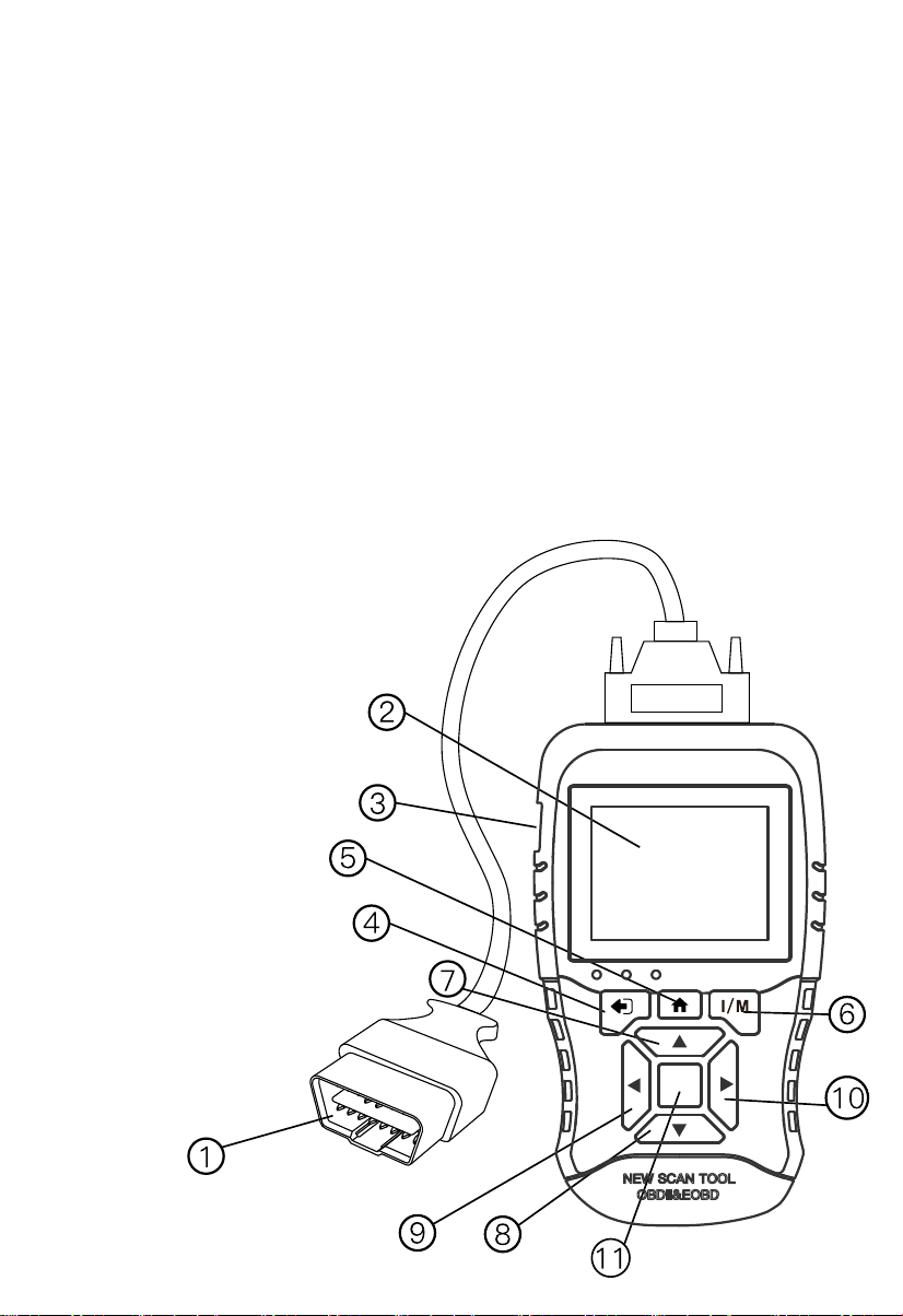
3.Product Instructions
3.1 Tool Description
OK
9

1. OBD II Cable:Connects the Scan Tool to the vehi-
cles DLC.
2. LCD Screen: Indicates test results.
3. USB Connector: Connects the Scan Tool to a PC for
updating software and printing.
4. ESC Button: Returns to the previous screen. Checks
Datastream after selecting specific data items.
5. Home Button: Moves to main function interface.
6. I/M Button: One-key I/M Readiness operations.
7. Up Button: Moves up through menu and submenus.
Moves to previous screen if information covers more
than one screen.
8. Down Button: Moves down through menu and sub-
menus. Moves to next screen if information covers more
than one screen.
9. Left Button: Moves to previous screen if information
covers more than one screen.
10. Right Button: Moves to next screen if information
covers more than one screen.
11. OK Button: Conforms a selection from a menu.
3.2 Specifications
Display Screen TFT Color (320*240)
0 to 60℃ (32 to 140℉)
-20 to 70℃ (-4to 158℉)
8V to 18V (power provided by vehicle battery)
Operating Temperature
Storage Temperature
Power
10

3.3 Accessories Included
1. User's Manual-- Instructions on tool operations.
2. OBDII cable-- Provides power to tool and communi-
cation between tool and vehicle.
3. USB cable -- Used to print retrieved data and
update software.
4. Protective ABS Case--A ABS case to store the tool
when not in use.
3.4 Keyboard
No solvents such as alcohol are allowed to clean the
keypad or display. Use a mild nonabrasive detergent
and a soft cotton cloth. Do not soak the keypad as the
keypad is not waterproof.
3.5 Power
The scan tool is powered via the vehicle Data Link
Connector (DLC).
Just follow the steps below to turn on the scan tool:
1.Connect the OBD II Cable to scan tool.
2.Find DLC on vehicle.
3.Plug OBD II cable to the vehicle's DLC.
Power up the scan tool, and wait for the Main Screen to
appear.
3.2 Specifications
11
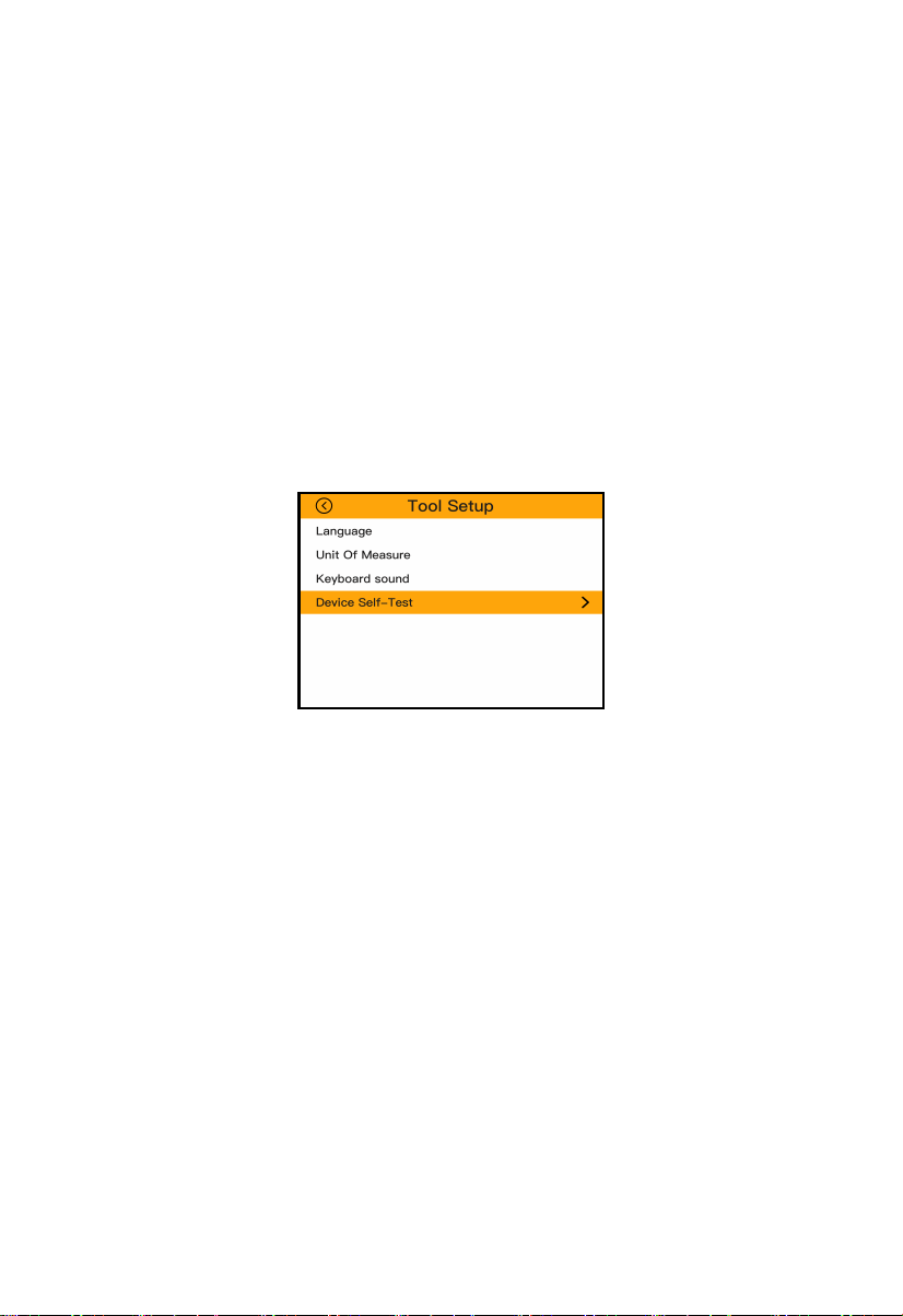
3.6 System Setup
The System Setup functions allow you to adjust default
settings and view information about the scan tool.
1.Language: Selects the desired language.
2.Unit of measure: Sets the unit of measure to English or
Metric.
3.Beep Set: Turns on/off beep.
4.Key Test: Checks if the keyboard is working properly.
5.LCD Test: Checks if the LCD display is working properly.
6.Screen Test:Checks if the screen is working properly.
To enter the Setup menu
From the Main Screen: Use LEFT/RIGHT scroll button
to select Setting, and press the OK button. Following
the instructions to do adjustments and settings could
make your diagnosis more conveniently and easily.
Language setup
English is the default language.
1) Use the UP/DOWN scroll button to select the desired
language and press the OK button to save your selec-
tion and return to previous screen.
12

Unit of Measure
Metric is the default measurement unit.
1) From Unit of Measure screen, use the OK button to
select the desired unit of measurement.
Keyboard Sound
The default setting is Beep On.
1) From Beep Set menu, use the OK button to select
ON or OFF to turn on/off the beep.
Key Test
The Key Test function checks if the keyboard is working
properly.
1) Press any key to start test. When you press a key,
the name of corresponding key will show on the screen.
Otherwise, the key is not functioning properly.
2) Double press ESC to return to previous menu.
LCD Test
The LCD Test function checks if the LCD display is
working normally.
1) Look for missing spots in the red, green, yellow LCD
display.
2) When completed, press the ESC button to exit.
3.7 Vehicle Coverage
The Scan Tool is specially designed to work with all
OBD II compliant vehicles, including those equipped with
next-generation protocol- Control Area Network (CAN).
13

It is required by EPA that all 1996 and newer vehicles
(cars and light trucks) sold in the United States must be
OBD II compliant and this includes all Domestic. Asian
and European vehicles.
A small number of 1994 and 1995 model year gasoline
vehicles are OBD II compliant. To verify if a 1994 or
1995 vehicle is OBD II compliant, check the Vehicle
Emissions Control Information (VECI) Label which is
located under the hood or by the radiator of most vehi-
cles. If the vehicle is OBD II compliant, the label will
designate "OBD II Certified". Additionally, Government
regulations mandate that all OBD II compliant vehicles
must have a"common sixteen-pin Data Link Connector
(DLC).
For your vehicle to be OBD II compliant it must have a
16-pin DLC under the dash and the Vehicle Emission
Control Information Label must state that the vehicle is
OBD II compliant.
3.8 Product Troubleshooting
This part describes problems that you may encounter
while using the scan tool.
Problem Possible Cause Likely Solutions
Scan Tool doesn't
power up
1.OBDII Cable connector not
connected securely.
2. Vehicle's DLC pins are
bent or broken.
3. Vehicle's battery is bad.
1.Verify that the Scan Tool's
OBDII Cable connector is
securely connected to the
vehicle's DLC.
2.Check if the DLC pins are
bent or broken.If bent or
broken,have a certified
technician repair the DLC.
3.Make sure vehicle's
battery it providing at least
8V.
14

4. OBDII Diagnosis
The OBD II Diagnostics function is a fast-access option
that allows you to carry out a quick test on the engine
system of OBD II. When more than one vehicle control
module is detected by the scan tool, you will be
prompted to select the module where the data may be
retrieved. The most often to be selected are the Pow-
er-train Control Module [PCM] and Transmission Con-
trol Module [TCM].
CAUTION: Don't connect or disconnect any test equip-
ment with ignition on or engine running.
1) Turn the ignition off.
2) Locate the vehicle's 16-pin Data Link Connec-
tor(DLC).
3) Plug the scan tool cable connector into the vehicle's
DLC.
4) Turn the ignition on. Engine can be off or running.
Vehicle Linking
Error
1. Vehicle is not OBD
compliant.
2. Ignition is off.
3. Bad connection.
1.Verify that the vehicle is
OBDII compliant.
2.Verify that the ignition is
ON.
3.Reset the tool by turning
the ignition off,waiting 10
seconds,then turning the
ignition back on.
Scan Tool Freezes Scan Tool or vehicle's
computer system
not responding.
Reset the Scan Tool by
turning the ignition off,
waiting 10 seconds,then
turning the ignition back on.
Problem Possible Cause Likely Solutions
15

5) Turn on the scan tool. Select OBDII from the Main
Screen.
6) Press the OK button to wait for the Menu to appear.
A sequence of messages displaying the OBDII protocols
will be observed on the display until the vehicle protocol
is detected.
4.1 Read DTC
1.Use UP/DOWN scroll button to select Read DTC from
Main Menu and press OK button.
2.Use the UP/DOWN scroll button to select Stored
Codes, Pending Codes or Permanent Codes from the
Read Codes menu and press the OK button.
If there is not any Diagnostic Trouble Code, the display
indicates “No(pending) codes are stored in the
module!” Wait a few seconds or press any key to return
to previous screen.
NOTE: Permanent Codes function is available for merely
vehicles supporting the CAN protocols.
Read Codes
Current DTC ($ 03)
Pending DTC ($ 07)
Permanent DTCs ($ 0A)
Record DTC
16

3.View DTCs and their definitions on screen
4.If more than one DTC is found, use the UP/DOWN
scroll button to check all the codes.
If retrieved DTCs contain any manufacturer specific or
enhanced codes, a"The vehicle’s code is defined by the
manufacturer, please enter to select the manufactur-
er."message comes up prompting you to select vehicle
manufacturer to view DTC definitions. Use UP/DOWN
scroll button to select manufacturer and then press OK
button to confirm.
If the manufacturer of your vehicle is not listed, use the
UP/DOWN scroll button to select Other and press the
OK button.
4.2 Clear DTC
CAUTION: Erasing the Diagnostic Trouble Codes may
allow the scan tool to delete not only the codes from
the vehicle's on-board computer, but also "Freeze
Frame" data and manufacturer specific enhanced data.
Further, the IM Readiness Monitor Status for all vehicle
monitors is reset to Not Ready or Not Complete status.
Do not erase the codes before the system has been
checked completely by a technician.
P0010 1/11
A Camshaft Position Actuator
Circuit/Open Bank 1
Read Codes
17

NOTE: Erasing codes does not mean that trouble codes
in ECU have been eliminated completely. As long as
there is fault with the vehicle, the trouble codes keeps
on presenting.
This function is performed with key on engine off
(ROEO). Do not start the engine.
1.Use the UP/DOWN scroll buttons to select Clear DTC
from Diagnostics Menu and press the OK button.
2.Choose whether to erase codes or not.
4.3 Live Data
In this function, you can not only read the live data but
also record data for later review.
Viewing Data: allows viewing of live or real time PID
data of vehicles computer module(s).
To view live data, use the UP/DOWN scroll button to
select Live Data from Diagnostic Menu and press the
OK button.
A.View All Items
1.To view complete set of data, use UP/DOWN scroll
button to select View All Items from Live Data menu
and press the OK button.
View All Items
< 1/18 >
Fuel system 1 status ---
Fuel system 2 status CL
Calculated LOAD Value 96.1%
-21.1%
118℉
Engine Coolant
Temperature
Short Term Fuel Trim-
Bank 1
18
2.View live PIDs on the screen. Use the UP/DOWN or
Left/Right scroll button for more PIDs if additional in
formation is available on more than one page.
B. Select Items
To view customized PID data, click Select Items from
Live Data menu and press the OK button.
1.Use the UP/DOWN scroll button to get the desired
items and click OK button to confirm.
2.Press ESC to view the selected PIDs.
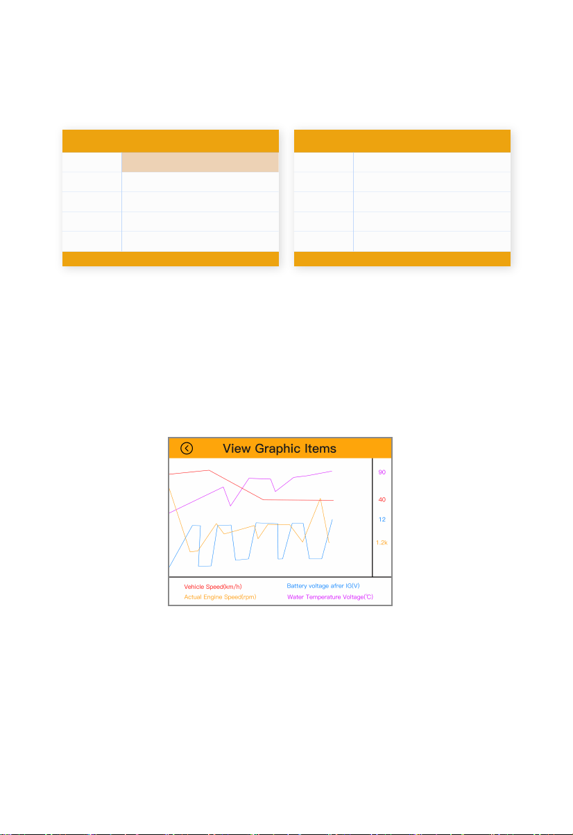
C. View Graphic Items
1. Use the UP/DOWN scroll button to get the desired
items and click OK button to confirm. 见图5.15
2. Press ESC to view the selected PIDs.
NOTE: Merge Graph can be used to compare four
related parameters in graphic mode.
Select Items
< 1/18 >
Fuel system 1 status[ ]
[ ]
[ ]
[ ]
[ ]
Fuel system 2 status
Calculated LOAD Value
Engine Coolant
Temperature
Short Term Fuel Trim-
Bank 1
Select Items
< 1/18 >
Fuel system 1 status[√]
[√]
[√]
[√]
[√]
Fuel system 2 status
Calculated LOAD Value
Engine Coolant
Temperature
Short Term Fuel Trim-
Bank 1
19

Recording Data
A. Record All
1. Use UP/DOWN scroll button to select Record All
from Live Data menu and press the OK button.
2. The scan tool will start timing to record retrieved live
data.
3. Press ESC to stop recording.
4. You may review the recorded data in Review func-
tion.
B. Record Select
1. Use UP/DOWN scroll button to select Record Select
from Live Data menu and press the OK button.
2. Use the UP/DOWN scroll button to get the desired
items,then press ESC, the scan tool will start timing to
record selected live data.
3. Press ESC again to stop recording.
4. You may review the recorded data in Review func-
tion.
Data Stream
View All Items
Select Items
View Graphic Items
Record All
Record Select
Selected Datastream
< 1/17 >
DTC that caused required freeze
frame data storage
P0113
Fuel system 1 status ---
Fuel system 2 status CL
24.1%
194℉
Calculated LOAD Valus
Engine Coolant Temperature
Select Datastream
< 1/16 >
Calcultated LOAD Value[ ]
[ ]
[ ]
[ ]
[ ]
Engine Coolant Temperature
Short Term Fuel Trim-Bank 1
Long Term Fuel Trim-Bank 1
Short Term Fuel Trim-Bank 2
20
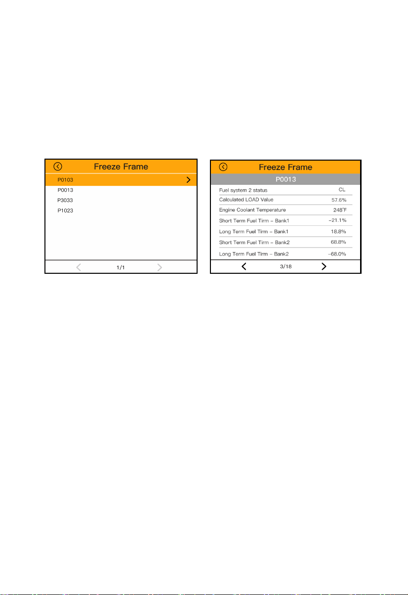
4.4 Freeze Frame
Freeze Frame Data allows the technician to view the
vehicle's operating parameters at the moment a DTC is
detected. For example, the parameters may include
engine speed (RPM), engine coolant temperature(ECT),
or vehicle speed sensor (VSS)etc.
1.Select Freeze Frame from Diagnostic Menu and press
the OK button.
2.View data. If retrieved information covers more than
one screen, use the DOWN scroll button as necessary,
until all the data have been shown up.(Figure 5.20)
3.Select Save to record freeze frame.
21
4.5 I/M Readiness
I/M Readiness function is used to check the operations
of the Emission System on OBD2 compliant vehicles. It
is an excellent function to use prior to having a vehicle
inspected for compliance to a state emissions program.
CAUTION - By clearing trouble codes you also clear the
readiness status for the individual emission system
readiness tests. In order to reset these monitors, the
vehicle must be driven through a complete drive cycle
with no trouble codes in memory. Times for reset vary
depending on vehicle.
Some latest vehicle models may support two types of
I/M Readiness tests:
A. Since DTCs Cleared - indicates status of the moni-
tors since the DTCs are erased.
B. This Drive Cycle - indicates status of monitors since
the beginning of the current drive cycle.
An I/M Readiness Status result of "NO" does not nec-
essarily indicate that the vehicle being tested will fail
the state I/M inspection. For some states, one or more
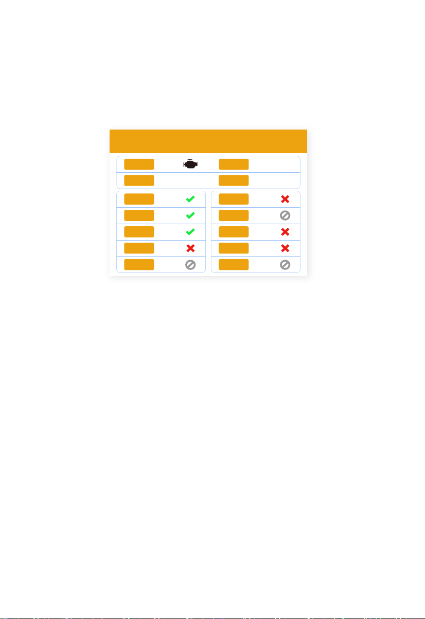
I/M Readiness
MIL
DTC
IGN Spark
Pd DTC
14 15
MIS
FUE
CCM
CAT
HCAT
EVAP
AIR
O2S
HRT
EGR
22

such monitors may be allowed to be "Not Ready" to
pass the emissions inspection.
-- Indicates that a particular monitor being checked
has completed its diagnostic testing.
-- Indicates that a particular monitor being checked
has not completed its diagnostic testing.
-- The monitor is not supported on that vehicle.
1.Press I/M Readiness button to enter.
2.Wait a few seconds while the scan tool validates the
PID MAP.
3.If the vehicle supports both types of tests, then both
types will be shown on the screen for selection.
4.Use the UP/DOWN scroll button, as necessary, to
view the status of the MIL light ("ON" or "OFF") and the
following monitors:
For spark ignition engines:
• MIS - Misfire Monitor
• FUEL -- Fuel System Monitor
• CCM - Comprehensive Component Monitor
• EGR - EGR System Monitor
• O2S -- O2 Sensors Monitor
• CAT -- Catalyst Monitor
• EVAP -- Evaporative System Monitor
• HTR -- O2 Sensor Heater Monitor
• AIR -- Secondary Air Monitor
• HCAT -- Heated Catalyst Monitor
23

For compression ignition engines:
• MIS -- Misfire Monitor
• FUEL -- Fuel System Monitor
• CCM -- Comprehensive Component Monitor
• EGR - EGR System Monitor
• HCCAT -- NMHC Catalyst Monitor
• NCAT -- NOx Aftertreatment Monitor
• BP -- Boost Pressure System Monitor
• EGS -- Exhaust Gas Sensor Monitor
• PM -- PM Filter Monitor
4.6 Smog Check
The Smog Check allows checking the smog readiness
status.
1.Select Smog from Diagnostic Menu and press OK
button.
2.You can clearly see the status of the smog readiness.
4.7 MIL Status
The MIL Status allows checking the status of MIL and
run time/ distance with Check Engine Light on, run
time/distance since DTC cleared.
1.Select MIL from Diagnostic Menu and press OK
button.
2.Use the UP/DOWN scroll button to select the item
you’d like to check.
Monitor Status
MIL Status
DTCs in this ECU
Readiness Completed
Readiness Not Completed
Readiness Not Supported
Datastream Supported
lgnition
Protocol Type
OFF
0
1
0
9
21
Spark
VPW
24

4.8 O2 Sensor
OBD2 regulations set by SAE require that relevant
vehicles monitor and tests on the oxygen (O2) sensors
to identify problem related to fuel efficiency and vehicle
emissions. These tests are not on-demand tests and
they are done automatically when engine operating
conditions are within specified limits. These test results
are saved in the on-board computer’s memory.
The O2 Monitor Test function allows retrieval and view-
ing of O2 sensor monitor test results for the most
recently performed tests from the vehicle's on board
computer.
The O2 Monitor Test function is not supported by vehi-
cles which communicate using a controller area network
(CAN). For O2 Monitor Test results of CAN-equipped
vehicles, see chapter“On-Board Mon. Test”
1.Use the UP/DOWN scroll button to select O2 sensor
from O2 Sensor menu and press OK button.
2.Wait a few seconds while the scan tool validates the
PID MAP.
If the vehicle does not support the mode, an advisory
message will be displayed on the screen.
3.View test results of selected O2 sensor.
Select O2 Sensor
Bank 1-Sensor1
Bank 1-Sensor2
25

4.9 Mode 6
Mode 6 (On-Board Monitor Test) is useful after servic-
ing or after erasing a vehicle's control module memory.
The On-Board Monitor Test for non-CAN-equipped
vehicles retrieves and displays test results for emis-
sion-related power train components and systems that
are not continuously monitored. The On-Board Monitor
Test for CAN-equipped vehicles retrieves and displays
test results for emission-related power train compo-
nents and systems that are and are not continuously
monitored. Test and components IDs are determined by
the vehicle manufacturer.
In this test, there are typically a minimum value, a maxi-
mum value, and a current value for each monitor. By
comparing the current value with the minimum and
maximum value, the scan tool will determine if it is OK.
1.From Mode 6 menu, use the UP/DOWN scroll button
to select a test to view and press the OK button.
2.Wait a few seconds while the scan tool validates the
PID MAP.
3.The scan tool will prompt you to select the vehicle
make. (If you have selected the vehicle before, the
Vehicle Manufacturer screen would not appear again)
On-Board Monitoring
Test $01 Data
Test $02 Data
Test $04 Data
Test $06 Data
Test $08 Data
Test $01 Data
Component ID $07
Limit Type Max
Test Value 0
128
---
Pass
Maximum Limit
Minimum Limit
Status
26

4.After you select the vehicle manufacturer, the scan
tool shows the On-Board Monitors tests for specific
monitoring systems.
If the vehicle under test does not support the mode,an
advisory message will be displayed on the screen.
4.10 Mode 8
Mode 8 (The Component Test) function allows initiating
a leak test for the vehicle's EVAP system. The scan tool
itself does not perform the leak test, but commands the
vehicle's on-board computer to start the test. Different
vehicle manufacturers might have different criteria and
methods for stopping the test once it has been started.
Before starting the Component Test, refer to the vehicle
service manual for instructions to stop the test.
1.Select Mode 8 from Diagnostic Menu and press the
OK button.
2.If the test has been initiated by the vehicle, a confir-
mation message will be displayed on the screen.
3.Some vehicles do not allow scan tools to control
vehicle systems or components. If the vehicle under test
does not support the EVAP Leak Test, an advisory
message is displayed on the screen.
Evap System(mode $8)
Evaporative system leak test passed
27

4.11 Viewing Vehicle Information
The Vehicle Info. function enables retrieval of Vehicle
Identification No. (VIN), Calibration ID Nos.(CINs), Cali-
bration Verification Nos.(CVNs) .
1.Select Vehicle Info. from the Diagnostic Menu and
press OK button.
2.View retrieved vehicle information on screen.
4.12 Fuel Analysis
The Fuel Analysis function allows viewing the fuel econ-
omy of the vehicle.
1.Select Fuel from Diagnostic Menu and press OK
button.
2. Use the UP/DOWN scroll button to select the item
you'd like to check if there is more than one page.
Vehicle Information
Vehicle Identification Number(VIN):
LFV3A24G9D3020130
CID1: JMB*36761500
CVN1: 4A4D422A
CVN2: 33363736
Calibration Identifications(CID):
Calibration Verification Numbers(CVN):
Fuel Economy
< 1/17 >
Instant fuel consumption
519.9L/
100KM
Idle speed fuel consumption ---
Vehicle speed 26MPH
86.71b/min
2749/min
Air Flow Rate from Mass Air Flow
Sensor
Engine RPM
28

4.14 Engine Analysis
The Engine Analysis function allows viewing the engine
data of the vehicle.
1. Select Engine from Diagnostic Menu and press OK
button.
2. Use the UP/DOWN scroll button to select the item
you'd like to check if there is more than one page.
4.13 Core Analysis
The Core Analysis function allows viewing the perfor-
mance of the vehicle.
1.Select Core from Diagnostic Menu and press OK
button.
2. Use the UP/DOWN scroll button to select the item
you'd like to check if there is more than one page.
Performance
< 1/17 >
Engine RPM
2749/min
Vehicle Speed 26mph
Engine Coolant Temperature 419℉
32℉
0.0psi
Intake Air Temperature
Fuel Rail Pressure
29

4.15 Battery Test
The Battery Test function allows viewing the status and
the voltage of the vehicle.
1.Select Battery from Diagnostic Menu and press OK
button.
2.You can clearly see the status and the voltage of the
vehicle.
4.16 DTC Query
The DTC Query function allows user to search defini-
tions of DTC stored in built-in DTC library.
1.Use the UP/DOWN scroll button to select DTC Query
from Diagnostic Menu and press OK button.
2.Wait for the scan tool to display the DTC Query
screen.
Battery
Battery Volt
11.6V
Normal battery voltage, good battery status.
Engine: ON
DTC Lookup
Please input DTC:
P0000
The 1st range: P. C. B. U
The 2nd range: 0. 1. 2. 3
The others from 0 to F
Press [up] or [down] to change input, press [
Left] or [Right] to select position, then press [
ok] to confirm.
30

3.Press UP/DOWN to change input,press LEFT/RIGHT
to select position. Then press OK button to confirm and
the scan tool will display this code's definition on
screen.
If definition could not be found(SAE or Manufacturer
Specific), the scan tool displays"The fault code is not
found in the database"
4.Press ESC button to return to previous menu.
5. Review and Print Data
The Review function allows viewing data from last test
recorded by the scan tool.
5.1 Reviewing Data
1. Select Review from Main Screen, and press the OK
button.
2. Use the UP/DOWN scroll button to select the item
you'd like to review. Then press OK button to continue.
3. Review selected data on screen.
If no data from previously tested vehicle is recorded, a
message "No data available!" shows on the screen.
4. If you'd like to delete the saved data, select Review
from Main Scree, and then choose the one you want to
delete and press OK.
Print Data
Print All
Print Data Stream
Print Freeze Data
Print DTC
31

5.2 Printing Data
The Print Data function allows printing out diagnostic
data recorded by the scan tool by connecting the scan
tool to a PC or laptop with the USB cable supplied. To
print out retrieved data, you need the following tools:
NT510 Scan tool
A PC or laptop with USB ports
A USB cable
1.Download the applications in our website: www.VX-
DAS.com or our distributors’ site.
2.Connect the scanner to computer with the USB cable
supplied.
3.Run Printer software on computer.
4.Select Print function in Main Screen of the scan tool.
In Scan screen, select the files you want to print. Wait
for the reviewing window to display , and then select
Print function. The selected file will be uploaded to your
computer.
5.The selected data will display on the textbox of Print-
er. By selecting the function keys on the right , you are
also allowed to edit, copy, and delete the data in the
Printer window.
NOTE: The scan tool can only print text data even
32

6.Update and Warranty
6.1 Software Update
This function allows you to update the scan tool soft-
ware through a computer.
Update Procedure
VXDAS frequently releases software updates that you
can download. The Update feature makes it very easy
to determine and get exactly what you need.
1.Download the applications in our website: www.VX-
DAS.com or our distributors' site.
2.Make sure that your computer is connected to the
Internet.
3. Connect the scanner to computer with the USB cable
supplied.
4. Run the update option in PC Suit software. Wait for
the log in window to pop up.
5. In the Update window, select the items you want to
install.
6.2 Limited One Year Warranty
VXDAS warrants to its customers that this product will
be free from all defects in materials and workmanship
for a period of one (1) year from the date of the original
purchase, subject to the following terms and conditions:
1) The sole responsibility of Humzor under the Warranty
is limited to either the repair or, at the option of VXDAS
replacement of the scan tool at no charge with Proof of
Purchase. The sales receipt may be used for this pur-
pose.
33

2) This warranty does not apply to damages caused by
improper use, accident, flood, lightning, or if the prod-
uct was altered or repaired by anyone other than the
Manufacturer's Service Center.
3) VXDAS shall not be liable for any incidental or con-
sequential damages arising from the use, misuse, or
mounting of the scan tool. Some states do not allow
limitations on how long an implied warranty lasts, so the
above limitations may not apply to you.
4) All information in this manual is based on the latest
information available at the time of publication and no
warranty can be made for its accuracy or completeness.
VXDAS reserves the right to make changes at any time
without notice.
6.3 Service Procedures
If you have any questions, please contact your local
store, distributor or visit our website at
www. VXDAS.com.
If it becomes necessary to return the scan tool for
repair, contact your local distributor for more informa-
tion.
34

Address: Fuquan Building A709, Qingquan Road ,Longhua New District,518131 Shenzhen, China
Website: www.vxdas.com
Email: [email protected]