
Front Loader w/ 60" Bucket
Model 59A40003727
769-03185C
(6/10)
Cub Cadet Yanmar LLC
P.O. Box 361052
Cleveland, Ohio 44136-1052
PRINTED IN U.S.A.
Operator’s
Manual

Table of Contents
Content Page
Safe Operation Practices ................................................................................................................................ 3
Safety Labels .................................................................................................................................................. 6
Loader Specifications ..................................................................................................................................... 7
To the Dealer ................................................................................................................................................... 8
To the Owner ................................................................................................................................................... 8
Contents ......................................................................................................................................................... 8
Unpacking the Loader .................................................................................................................................... 9
Initial Installation ............................................................................................................................................. 10
Dismounting and Mounting the Loader .......................................................................................................... 14
Operation ......................................................................................................................................................... 15
Maintenance .................................................................................................................................................... 21
Troubleshooting ............................................................................................................................................... 22
Parts List ......................................................................................................................................................... 24
Warranty .......................................................................................................................................................... 27
Finding Model Number
This Operator’s Manual is an important part of your new front-end loader. It will help you assemble, prepare and maintain the equipment
for best performance. Please read and understand what it says.
Before you start assembling your new equipment, please locate the model plate on the equipment and copy the information
from it in the space provided below. The information on the model plate is very important if you need help from our Customer
Support Department or an authorized dealer.
• You can locate the model number by looking on the loaders left-hand mast assembly. A sample model plate is shown below. For
future reference, please copy the model number and the serial number of the equipment in the space below.
Calling Customer Support
If you have difficulty with this front-end loader; have any questions regarding the controls, operation or maintenance of this equipment; or
desire additional information not found in this manual, contact your nearest authorized Cub Cadet Yanmar dealer. If you need assistance
in locating a dealer in your area, contact the Customer Dealer Referral Line.
Call 1-(877) 282-5055 to reach the Customer Dealer Referral Line. Please have your front-end loader model number and serial number
ready when you call. See previous section to locate this information. For more details about your equipment, visit our website at:
www.cubcadetyanmar.com.
Cub Cadet/YanmarLLC
CLEVELAND, OHIO 44136
Copy the model number here:
Copy the serial number here:
Model Number
Serial Number
xxxxxxxxxxxxx
xxxxxxxxxxxxx
P.O. Box 361052
www.cubcadetyanmar.com
Dealer Locator Phone Number: 877-282-5055
2

WARNING! This symbol points out important safety
instructions which, if not followed, could endanger the
personal safety and/or property of yourself and
others. Read and follow all instructions in this manual
before attempting to operate this machine. Failure to
comply with these instructions may result in personal
injury. When you see this symbol—HEED ITS
WARNING.
DANGER! This machine was built to be operated
according to the rules for safe operation in this
manual. As with any type of power equipment,
carelessness or error on the part of the operator can
result in serious injury. Failure to observe the following
safety instructions could result in serious injury or
death.
TRAINING
1. Safety instructions are important! Read this manual and the
tractor’s Operator’s Manual; follow all safety rules and safety
label information. (Replacement labels are available through
your Cub Cadet Yanmar dealer.) Failure to follow instructions
or safety rules can result in serious injury or death.
2. If you do not understand any part of this manual and need
assistance, contact your Cub Cadet Yanmar dealer.
3. Know your controls and how to stop engine and attachment
quickly in an emergency.
4. Operators must be instructed in and be capable of the safe
operation of the equipment, its attachments and all controls.
Do not allow anyone to operate this equipment without proper
instructions.
5. Keep hands and body away from pressurized lines. Use paper
or cardboard, not body parts to check for leaks. Wear safety
goggles. Hydraulic fluid under pressure can easily penetrate
skin and will cause serious injury or death.
6. Make sure that all operating and service personnel know that
in the event hydraulic fluid penetrates skin, it must be surgi-
cally removed as soon as possible by a doctor familiar with this
form of injury, or gangrene, serious injury or death will result.
CONTACT A PHYSICIAN IMMEDIATELY IF FLUID ENTERS
SKIN OR EYES. DO NOT DELAY.
7. Do not allow children or untrained persons to operate equip-
ment.
INSTALLATION
1. During installation, the tractor engine should be off, the key
removed and the parking brake engaged.
2. Do not disconnect hydraulic lines until attachments are
removed or lowered to the ground and system pressure is re-
leased by operating valve levers. Never operate any hydraulic
cylinders during any phase of the installation process.\
3. After connecting hoses, check that all control lever positions
function as instructed in this Operator’s Manual. Do not oper-
ate until control lever and equipment movements are correct.
PREPARATION
1. Check that all hardware is tight and properly installed. Always
tighten to torque specifications as instructed in this manual.
2. Air in hydraulic systems can cause erratic operation and allows
loads or equipment components to drop unexpectedly.
3. Before operating or allowing anyone to approach the equip-
ment, purge any air in the system by operating all hydraulic
functions several times after connecting equipment, connect-
ing hoses, or doing any hydraulic maintenance.
4. After connecting hoses, check that all control lever positions
function as Instructed in this Operator’s Manual. Do not oper-
ate until control lever and equipment movements are correct.
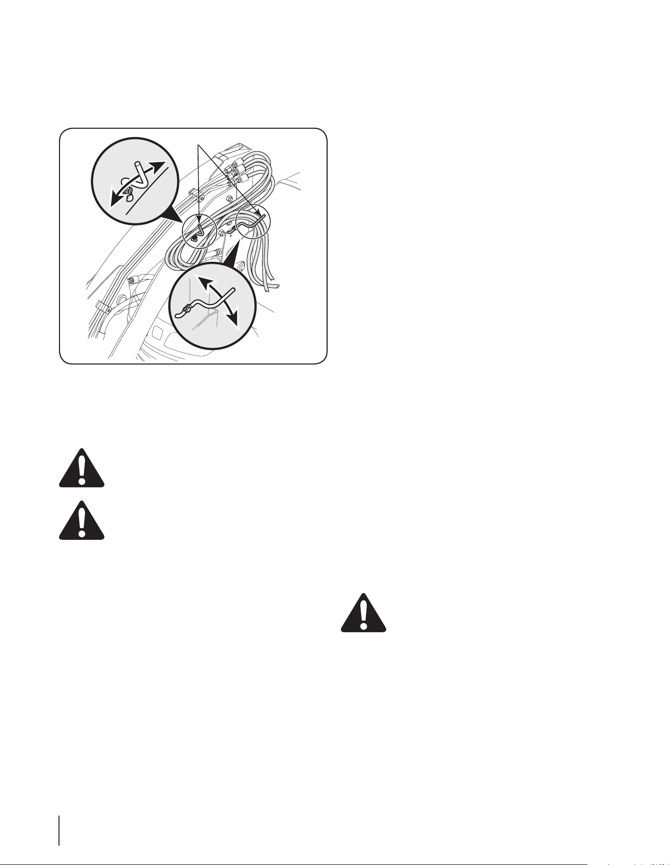
5. Protective sleeves must be over hydraulic hoses and securely
fastened onto metal hose fittings as described in this manual.
Replace if damaged or if protective sleeve is not properly
positioned or secured.
6. Make sure all hydraulic hoses, fittings and valves are in good
condition and not leaking before starting power unit or using
equipment. Check and route hoses carefully to prevent dam-
age. Hoses must not be twisted, bent sharply, kinked, frayed,
pinched, or come into contact with any moving parts. Operate
moveable components through full operational range to check
clearances. Replace any damaged hoses immediately.
7. Always wear relatively tight and belted clothing to avoid
entanglement in moving parts. Wear sturdy, rough-soled work
shoes and protective equipment for eyes, hair, hands, hearing
and head.
8. Avoid injury or death. Never work under a raised loader.
Always lower loader to the ground with bucket or loader
attachment in full roll-back position. Operate valve levers
to release any hydraulic pressure. If loader obstructs tractor
maintenance, loader must be removed from tractor.
9. Do not modify or alter or permit anyone else to modify or alter
the equipment or any of its components in any way.
10. Your Cub Cadet Yanmar dealer can supply original equipment
hydraulic accessories and repair parts. Substitute parts may
not meet original equipment specifications and may be danger-
ous.
11. Ensure implement is properly attached, adjusted and in good
operating condition.
12. Power unit must be equipped with ROPS or ROPS CAB and
seat belt. Keep seat belt securely fastened. Falling off power
unit can result in death from being run over or crushed. Keep
foldable ROPS systems in locked up position at all times.
13. Ensure all safety labels are installed. Replace if damaged.
(See Safety Labels later in this section).
14. Ensure shields and guards are properly installed and in good
condition. Replace if damaged.
3
SECTION 1: SAFE OPERATION PRACTICES

OPERATIONAL
1. Do not allow other people in the area when operating, attach-
ing, removing, assembling or servicing equipment.
2. Improper use of a loader can cause injury or death.
3. Consult local utilities before working. Know location of and
avoid contacting all underground cables, pipelines, overhead
wires and other hazards in working area.
4. Do not attempt to lift loads in excess of the loader capacity.
5. Keep bystanders away from equipment.
6. Do not walk or work under a raised loader, bucket or attach-
ment.
7. Never allow anyone to get under the loader bucket or reach
through the lift arms when the bucket is raised.
8. Do not operate equipment while under the influence of alcohol
or drugs.
9. Operate only in daylight or good artificial light.
10. Always comply with all state and local lighting and marking
requirements.
11. Do not allow riders. Do not lift or carry anybody on the loader
or in the bucket or attachments.
12. Power unit must be equipped with ROPS or ROPS CAB and
seat belt. Keep seat belt securely fastened. Falling off power
unit can result in death from being run over or crushed. Keep
foldable ROPS systems in “locked up” position at all times.
13. Always sit in tractor seat when operating controls or start-
ing engine. Securely fasten seat belt, place transmission
in neutral, engage brake and ensure all other controls are
disengaged before starting tractor engine.
14. Look down and to the rear and make sure area is clear before
operating in reverse.
15. Avoid loose fill, rocks and holes. They can be dangerous for
loader operation or movement.
16. Allow for loader length and width when making turns.
17. Stop the loader arms gradually when lowering or lifting.
18. Use caution when handling loose or shiftable loads.
Avoid Injury or Death from Rollover Accidents:
• Move and turn tractor at low speeds.
• Watch for hidden hazards such as holes, ditches, and other
obstructions which may cause tractor and loader to tip over.
• Carry loads close to the ground to aid visibility and lower
center of gravity for improved stability.
• Balance loads so weight is evenly distributed and load is
stable.
• Be extra careful when operating on a slope.
• Do not operate on steep slopes.
• Do not stop, start or change directions suddenly on slopes.
• If loader is equipped with round bale attachments, always
approach bale with tractor facing uphill.
• Tractor must be equipped with a Roll-Over Protective Structure
(ROPS) and seat belt.
• Keep seat belt securely fastened and keep foldable ROPS
systems in “locked up” position at all times.
Avoid Injury or Death from Power Lines
• Stay away from power lines. Electrocution can occur without
direct contact.
• Check clearances before raising loader.
• Consult local utilities before digging. Know location of and
avoid contacting all underground cables, pipelines, overhead
wires and other hazards in digging area.
• Do not leave the operator’s seat if any part of the tractor or
loader contacts electric lines or underground cables.
Avoid Injury or Death from Falling Objects:
• This loader is not equipped with any method to prevent objects
such as round bales, posts, logs, etc. from rolling back onto
operator.
• Do not carry large objects that can fall out of loader bucket into
operator zone.
• Never lift loader higher than necessary to clear the ground
when moving.
• Before dismounting tractor or performing any service or
maintenance, disengage the power to the implement, lower the
3-point hitch and all raised components to the ground, operate
valve lever to release any hydraulic pressure, stop engine, set
parking brake, remove key, and unfasten seat belt.
• Never work under a raised loader. Always lower loader to
the ground with bucket or loader attachment in full roll-back
position. Shut off tractor, set park brake and remove key.
Operate valve levers to release any hydraulic pressure. If
loader obstructs tractor maintenance, loader must be removed
from tractor.
MAINTENANCE
1. Before dismounting tractor or performing any service or
maintenance, disengage power to implement, lower the 3-point
hitch and all raised components to the ground, operate valve
levers to release any hydraulic pressure, stop engine, set
parking brake, remove key, and unfasten seat belt.
2. Never work under a raised loader. Always lower loader to the
ground with bucket or loader attachment in full roll-back posi-
tion. Shut off tractor, set park brake and remove key. Operate
valve levers to release any hydraulic pressure.
3. Adjustment of system relief pressure should be done by a
qualified, experienced Cub Cadet Yanmar dealer. Incorrect
adjustment can result in system failures and serious personal
injury.
4

4. Always wear relatively tight and belted clothing to avoid
entanglement in moving parts. Wear sturdy, rough-soled work
shoes and protective equipment for eyes, hair, hands, hearing
and head.
.5 Do not allow other people in the area when operating, attach-
ing, removing, assembling or servicing equipment.
6. Ensure implement is properly attached, adjusted and in good
operating condition.
7. Keep all persons away from operator control area while
performing adjustments, service or maintenance.
8. Tighten all bolts, nuts and screws securely. Check that all
cotter pins are installed securely to ensure equipment is in a
safe condition before operating.
9. Ensure all safety labels are installed. Replace if damaged.
(See Safety Labels later in this section)
10. Ensure shields and guards are properly installed and in good
condition. Replace if damaged.
11. Do not disconnect hydraulic lines until all system pressure is
relieved. Lower unit to ground, stop engine, and operate all
hydraulic control levers.
12. When servicing or replacing pins in cylinder ends, buckets,
etc., always use a brass drift and hammer. Failure to do so
could result in injury from flying metal fragments.
STORAGE
Block equipment securely for storage. Stored loader can fall and
cause serious injury or death. Securely store loader and attach-
ments to prevent falling. To help prevent injury caused by a falling
implement, always:
1. Detach on a hard, level surface.
2. Keep children and bystanders away
3. Engage the tractor’s parking brake before detaching from
storage area.
To provide necessary balance, loader frame must be equipped with
bucket or attachment before attaching or detaching from tractor, or
when loader is in stored position.
1. Do not loosen hydraulic fittings or hoses while loader is in
stored position.
2. Do not climb or lean on equipment stored on stand.
WARNING! YOUR RESPONSIBILITY
Restrict the use of this attachment to persons who read, understand and follow the warnings and instructions in this manual,
the tractor’s Operator’s Manual and on the tractor and loader attachment. The safety labels found on the loader attachment
are illustrated on the following page
5
BUCKET LEVEL
REFERENCE POINT
INSTRUCTIONS
ASSEMBLY FOR FRONT END LOADER
1. PA RK LOADER ON FIRM
LEvEL GROUND.
2. SLOWLy DRIvE THE TR ACTOR
CLOSE TO THE LOADER. STOP
AND SET THE PA RKING BRAKE.
3. CONNECT COLOR CODED
HyDRAU LIC QUICK DISCONNECT
TO LOADER HOSES.
4. USE THE LOWER BOOM
CONTROL TO LOWER MASTS
ONTO RECEIvERS.
5. CONTINUE TO LOWER BOOM
UNTIL ALL WEIGHT IS OFF
THE FRONT TIRES.
6. LOCK LOADER MOUNTING
TUBE INTO RECEIvER WITH
Ly NCH PINS.
7. ADD HAIR-PINS TO Ly NCH
PINS (IMPORTANT TO PREvENT
Ly NCH PIN LOSS).
DISASSEMBLY FOR FRONT END LOADER
1. PA RK TRAC TOR ON FIRM
LEvEL GROUND.
2. USE THE LOWER BOOM
CONTROL TO TA KE ALL
WEIGHT OFF OF FRONT TIRES.
3. REMOvE Ly NCH PINS FROM
FRONT MOUNT ASSEMBLy.
4. USE THE RAISE BOOM
CONTROL UNTIL MASTS EXIT
THEIR RECEIvERS.
5. DISCONNEC T THE CO LOR
CODED HyDRAU LIC QUICK
DISCONNECTS.
6. SLOW Ly DRIvE AW Ay FROM
LOADER.
1. READ AND UNDERSTAND
OPERAT OR'S MANUAL
BEFORE OPERAT ING.
2. K EEP OTHERS AW Ay WHEN
OPERAT ING LOADER.
3. DO NOT ALLOW CHILDREN
OR UNTRAINED PERSONS
TO OPERATE EQUIPMENT.
4. LOWER LOADER TO GROUND ,
STOP ENGINE, SET PA RK
BRAKE AND REMOvE KEy BEFORE
LEAv ING TRAC TOR SEAT .
5. FA ILURE TO FOLLOW SAFETy
RULES CAN RESULT IN
SERIOUS INJURy OR DEAT H.
IMPORTANT
TO PREvENT POSSIBLE
TRANSMISSION DAMAGE, ENGAGE
THE 4WD ONLy WHEN ADDITIONAL
TRAC TION IS NEEDED WHILE
OPERAT
ING IN LOOSE SOIL OR ON
SLIPPERy SURFACES (E.G. MUD,
SNOW ), OR WHEN DESCENDING A
SLOPE. DISENGAGE THE 4WD
WHEN OPERAT ING
ON FIRM, FLAT
SURFACES OR WHEN OPERAT ING
AT HIGH SPEEDS.
WARNING
UP
DOWN
N
UP &
DUMP
DUMPCURL
FLOAT
READ OPERATORS MANUAL BEFORE OPERATING
UP &
CURL
DOWN &
CURL
21
3
4
DOWN &
DUMP
777S32188
777D11598
777I22804
777D11597
777D11594
On Both
Sides
777I22850
On Both
Sides
6
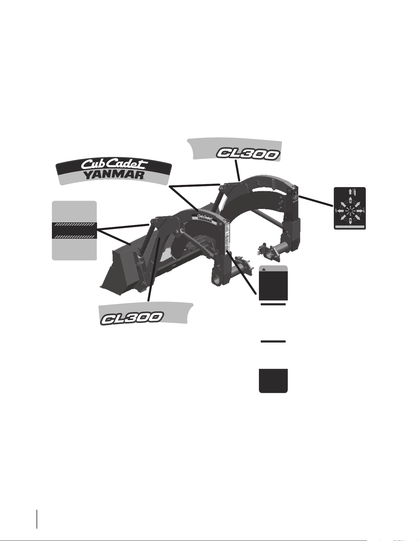
SECTION 2: LABELS
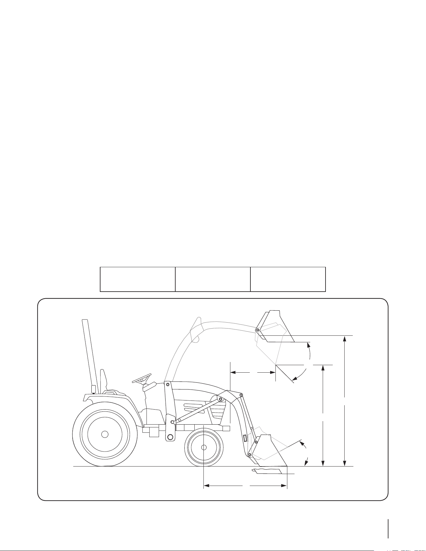
A Maximum Lift Height ........................................................................................................ 96”
B Clearance With Attachment Dumped ......................................................................... 77”
C Reach At Maximum Height ........................................................................................ 26”
D Maximum Dump Angle ............................................................................................... 45°
E Reach With Attachment On Ground........................................................................... 67”
F Attachment Rollback Angle ........................................................................................ 25°
G Digging Depth ............................................................................................................ 4”
Overall Height In Carrying Position ............................................................................ 54”
Length Of Attachment ................................................................................................ 18.06”
Lift Capacity To Full Height ........................................................................................ 900 lbs.
Breakout Capacity ...................................................................................................... 2500 lbs.
System Pressure Tested ............................................................................................ 1900 PSI
Recommended Hydraulic Flow .................................................................................. 4-7 GPM
Lift Cylinder Bore ........................................................................................................ 1-5/8”
Bucket Cylinder Bore ................................................................................................. 2”
Hose Working Pressure ............................................................................................. 3000 PSI
Bucket
60”
Bucket Capacity
9.0 cu. ft.
Weight
210 lbs
.
C
E
B
A
G
D
F
SECTION 3: MODEL 59A40003727 LOADER SPECIFICATIONS
7
Assembly and proper installation of this attachment is the responsibility of the Cub Cadet Yanmar dealer. Read the instructions and safety
precautions found in this manual carefully. Any and all front-end attachments installed on the tractor must first be removed in order to
properly install the Front-end Loader.
1
3
4
2
5
6
7
8
9
Figure 1
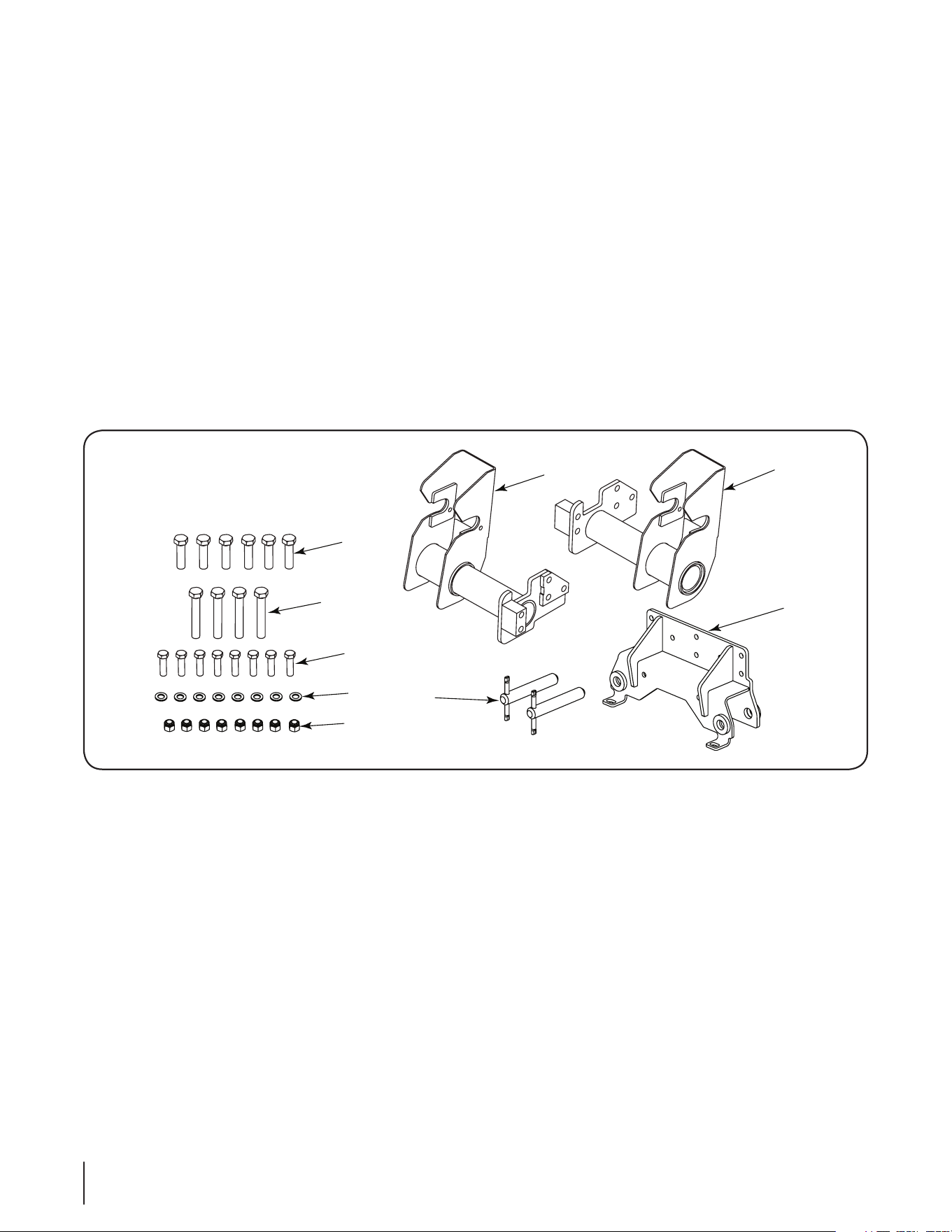
1. RH Mount ...........................................................603-04627 1 pc.
2. LH Mount ........................................................... 603-04626 1 pc.
3. Front Mount Receiver ...................................... 603-04629 1 pc.
4. Hx. Cp. Screw, M16-2.0 x 60 .......................... 710-04700 6 pc.
5. Hex Cap Screw, M16-2.0 x 100 ...................... 710-04701 4 pc.
6. Hex Cap Screw, 1/2-13 x 1.75 GR5 ................ 710-3067 8 pc.
7. Flat Washer ....................................................... 736-0192 8 pc.
8. Hex Lock Nut, 1/2-16 GR5 .............................. 712-3083 8 pc.
9. Mounting Pin .................................................... 711-05034A 2 pc.
Not Shown - Loader Bucket ................................. 603-04636 1 pc.
Not Shown - Complete Mast & Boom Assembly N/A 1 pc.
SECTION 4: TO THE DEALER
SECTION 5: TO THE OWNER
The front loader attachment components are listed below along with their part numbers. Assemblies are made up of more than one part
and do not have a part number. Before beginning installation, lay all components out on a flat surface to assure everything is present.
Throughout the manual the parts in the hardware pack will be identified by name, followed by their callout number in parenthesis, to aid in
installation.
Model 59A40003727 Front-end Loader is designed for use ONLY with specific Cub Cadet Yanmar tractor models. It will NOT fit nor
operate safely or properly on or with any other tractor.
References to LEFT and RIGHT indicate the left and right sides of the tractor when facing forward in the operator’s position. Reference to
the FRONT indicates the grille end; to the REAR the drawbar end.
SECTION 6: CONTENTS
8
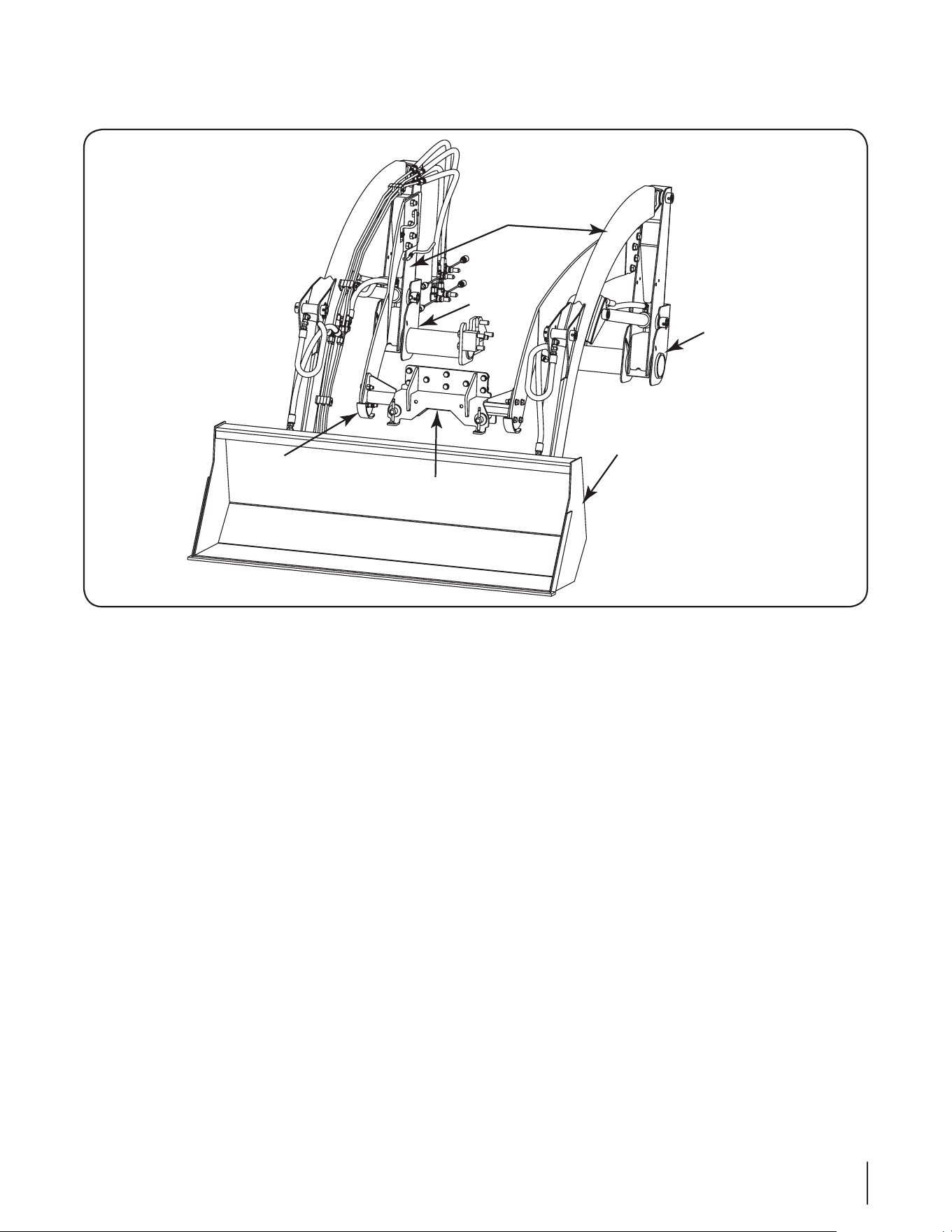
SECTION 7: UNPACKING THE LOADER
RH Mount
Boom & Mast
Assembly
LH Mount
Bucket
Assembly
Loader Hitch
Bracket
Front Mount
Reciever
Figure 2
Move the tractor and front loader to an area large enough to
accommodate both, and with access to an overhead lift. To uncrate
the loader and all components, refer to Figure 2 and proceed as
follows:
• Carefully remove the top and sides of the shipping crate and
carefully cut off the plastic wrapping.
• Remove the hardware pack from the shipping pallet. Check the
contents of the hardware pack against the list on page 8.
• Carefully remove and discard any banding wire, clamps, or
screws securing the loader bucket, RH and LH mounts, front
mount receiver, and the boom and mast assembly to the
shipping pallet.
• Remove the front mount receiver from the assembly. by remov-
ing the two lynch pins and withdraw the mounting pins from
the front mount receiver. Temporarily set aside the front mount
receiver and pins.
• Remove the RH and LH mount assemblies and set aside.
NOTE: Usage of an overhead lift apparatus is strongly recom-
mended to support and lift the boom and mast assembly when
performing the initial installation of the front loader. if an
overhead lift is not available, the aid of at least one assistant will be
necessary.
If Using an Overhead Lift
NOTE: When positioning the lifting devices, use care to avoid
damage to the hydraulic lines, while also maintaining the balance
of the boom and mast assembly.
If using lift straps and an overhead lift, position the straps around
the boom and mast assembly so that the assembly is balanced
when lifted from the shipping pallet.
• Carefully lift the loader assembly off the shipping pallet.
If an Overhead Lift is Not Available
• With the aid of at least one assistant, carefully maneuver the
loader assembly off the shipping pallet.
Carefully cut the shipping tie securing the free ends of the loader
hydraulic hoses to the right end of the loader hitch bracket.
Remove the packaging material from the hydraulic fittings on the
ends of the hoses.
9
SECTION 8: INITIAL INSTALLATION
TRACTOR PREPARATION
Remove the front weight bracket from the front of the tractor by
removing the six hex screws and nuts securing it to the front frame.
Store the front weight bracket for reinstallation when removing the
loader and attaching rear mounted equipment.
Installing the LH and RH Mounts
NOTE: the lH and RH mounts are heavy and awkward to handle.
Usage of a lifting device (e.g. floor jack), or the aid of an assistant,
while positioning the tower mounts for installation is recommended.
Install the RH and LH mounts as follows:
• Look at the RH mount (1) to note the configuration of the holes
on the mounting plate of the assembly.
• From the right side of the tractor, locate the three holes in a
triangular pattern on the tractor’s clutch housing, and the two
vertical holes on the front frame. Remove the protective plugs
from the holes See Figure 3.
NOTE: When positioning the RH mount on the tractor, be espe-
cially careful to avoid damaging the small hydraulic lines running
along the bottom of the frame. temporarily move the rubber hose
out of the way.
• Lift the RH mount (1) and carefully place against the tractor,
aligning its holes with the holes in the tractors clutch housing
and frame.
• Insert three hex cap screws (5) through the RH mount and
thread into the clutch housing. Insert two hex cap screws (6)
through the front of the mount and thread into the frame. In a
staggered pattern, evenly tighten the five hex cap screws to
secure the RH mount. Torque the screws to 145 - 167 ft. lbs.
(196-225 N•M). Refer to Figure 3.
• From the left side of the tractor, locate the mounting holes and
remove the protective plugs.
• Lift the LH mount (2) and carefully place against the tractor,
aligning its holes with the holes in the tractors clutch housing
and frame.
• Insert three hex cap screws (5) through the LH mount and
thread into the clutch housing. Insert two hex cap screws (6)
through the front of the mount and thread into the frame. In a
staggered pattern, evenly tighten all hex cap screws to secure
the LH mount. Torque the screws to 145 - 167 ft. lbs. (196-225
N•M). Refer to Figure 3.
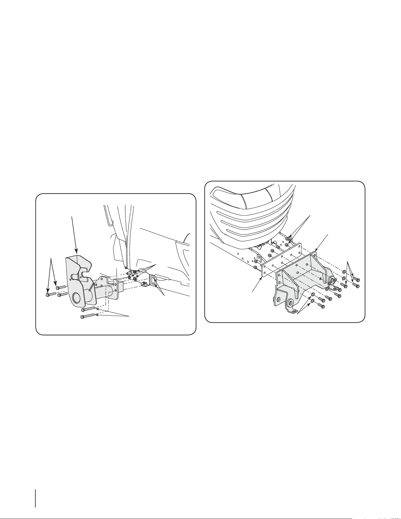
Installing the Front Mount Receiver
If not already done, remove the two lynch pins and withdraw the
mounting pins to separate the front mount receiver from the loader
hitch bracket (Refer to Figure 1).
• Slide a flat washer (8) onto each of the eight hex cap screws
(7). Refer to Figure 4.
• Position the front mount receiver (3) so that its open channel is
facing downward. Then place the front mount receiver against
the front of the tractor frame (where the front weight bracket
was previously removed).
• Align the eight holes in the front mount receiver with the
corresponding holes in the front frame. While holding the front
mount receiver in position, insert eight hex cap screws w/
washers through the front mount receiver and tractor frame.
See Figure 4.
• Thread a hex lock nut (9) onto each hex cap screw. In a
staggered pattern, evenly tighten all hex cap screws and lock
nuts. Torque the fasteners to 60-70 ft. lbs. (81-94 N•M).
Hex Cap
Screw
RH Mount
Clutch
Housing
Front
Frame
Hex Cap
Screw
Figure 3
Hex Cap
Screw
Hex Lock Nut
Front Mount
Receiver
Front
Frame
Flat Washer
Figure 4
10
FIRST INSTALLATION OF LOADER
ON TRACTOR
The initial installation of the front loader onto the tractor can be
accomplished by utilizing an overhead lift (strongly recommended),
or by pre-charging the loader hydraulic cylinders before beginning
the installation procedures.
The instructions in this sub-section apply only to the initial instal-
lation. Once the hydraulic lines and cylinders have been charged
with oil during the initial installation, the dismounting procedure
should leave the loader in position to be re-mounted.
WARNING! Some installation steps require the
tractor to be running and driven. Use caution when
completing these steps. Engage the parking brake
before dismounting the tractor. If working with an
assistant, make certain that person is made aware
that the tractor or any part of the loader is about to be
moved.
Using an Overhead Lift For Initial Installation
To complete the initial installation of the loader using an overhead
lift, proceed as follows:
• Using the overhead lift apparatus, raise the loader so that the
bottoms of the masts are high enough to clear the front axle/
tire of the tractor and the tubular bars of the RH and LH loader
mounts. Refer to Figure 5.
• Slowly drive the tractor forward while guiding the bottoms of
masts into the RH and LH mounts. Refer to Figure 6. Carefully
lower the overhead lift to set the notches at the bottom of the
masts partially onto the tubular bars of the mounts.
• Stop the tractor engine and set the tractor’s parking brake
before leaving the operator’s seat. Proceed to “Installing the
Front Loader” in this section.
Pre-Charging Cylinders for Initial Installation
If an overhead lift is not available, the front loader cylinders can be
used to position the loader for installation. To position the loader,
proceed as follows:
• Start the tractor and carefully drive the tractor to position it
along the right side of the front loader, facing in the opposite
direction of the loader.
NOTE: Stop the tractor engine and set the tractor’s parking brake
before leaving the operator’s seat.
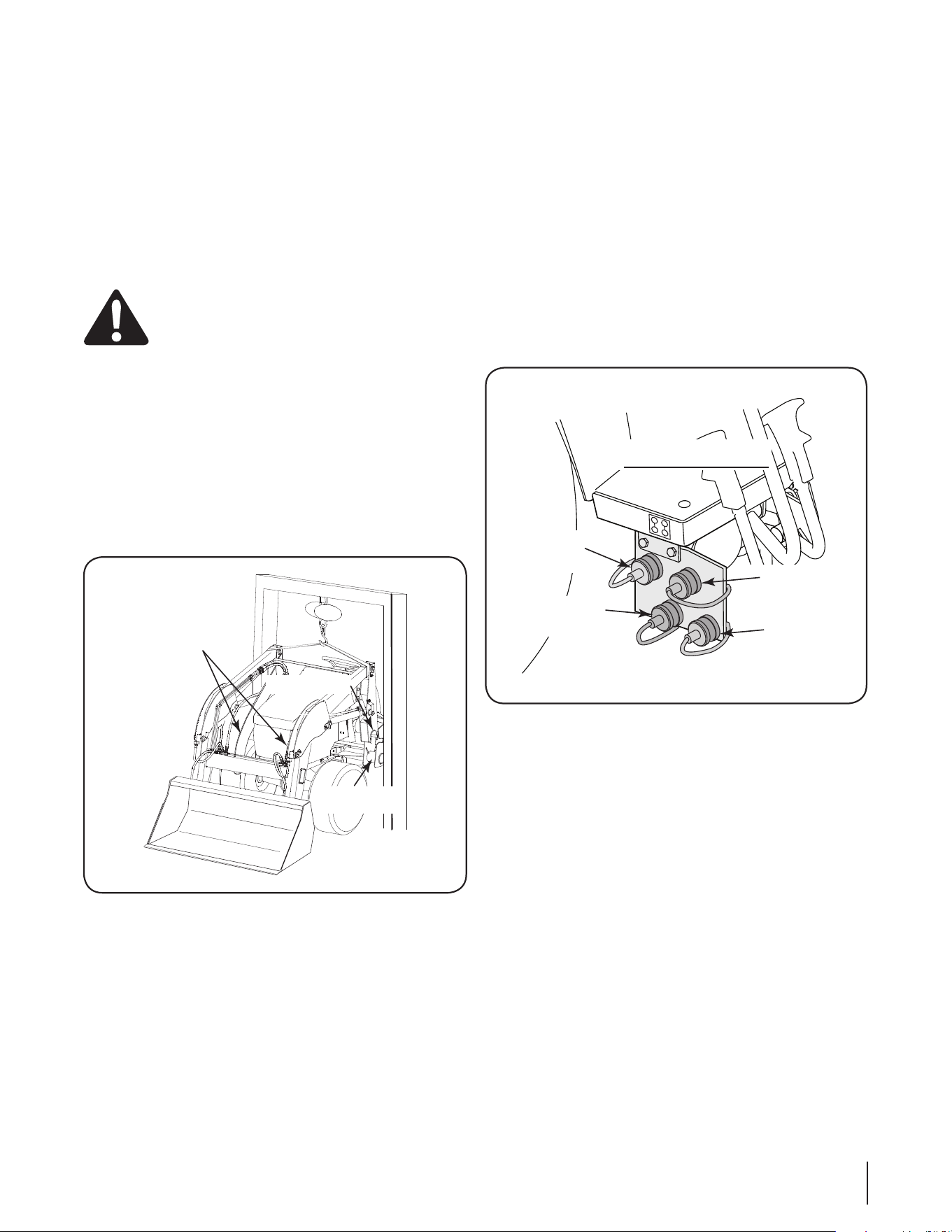
• Remove the four protective caps from the male couplers at the
free ends of the hydraulic hoses.
• Locate the color coded protective plugs in the female hydraulic
couplers on the lower right side of the tractor, just in front of
the right/rear tire. Refer to Figure 6.
• Using the color coded plugs and matching color coded wash-
ers on the loader hoses to guide you, remove the plugs and
connect each loader hose to the appropriate hydraulic coupler.
Refer to Figure 6.
NOTE: if for any reason the color coded plugs of the outlets and/or
caps and washers of the hoses are unavailable or incorrect, follow
the routing of each hydraulic hose/tube to the loader cylinders to
determine the loader connection of each hydraulic line. Use the
following information to determine the appropriate hose to hydraulic
outlet connection. Working from the right side of the tractor, facing
the hydraulic outlets, proceed as follows:
Outlet #1 (lower left) - connect the hydraulic line from the piston
ends of the bucket cylinders (roll back bucket).
Outlet #2 (upper left) - connect the hydraulic line from the cylinder
body ends of the bucket cylinders (dump bucket).
Outlet #3 (upper right) - connect the hydraulic line from the piston
ends of the boom cylinders (lower boom).
Outlet #4 (lower right) - connect the hydraulic line from the cylinder
body ends of the boom cylinders (raise boom).
2
1
3
4
Lower Boom
(#3-Blue)
Raise Boom
(#4-Green)
Dump Bucket
(#2-Yellow)
Curl Bucket
(#1-Red)
Hydraulic Outlets
Figure 6
LH
Mount
Tubular
Bar
Loader
Hitch Arms
Base of Mast
Figure 5
11
• Check for ties that may be installed end to end around both of
the boom cylinders. Cut and remove the ties if present.
NOTE: Re-start the tractor and perform the hydraulic test described
below in “Checking Implement Control Lever Operation” to
assure that all implement control lever movements result in the
loader movements described. if loader movements do not respond
correctly, turn the tractor’s engine off, set the parking brake and
recheck all hydraulic connections as described above. loader
control movements must be correct before proceeding.
NOTE: if you were unable to connect the pistons of the two bucket
cylinders to the bucket rear mounting brackets as instructed earlier,
use the tractor’s implement control lever to extend the pistons as
needed and connect the cylinders now.
WARNING! Use extreme caution when performing
the loader boom cylinder charging procedure.
NOTE: For packaging purposes the two boom cylinders are fully
collapsed. this results in the loader masts being positioned beyond
their normal vertical position, which causes the loader’s center of
gravity to be shifted rearward of normal. Consequently the loader
hitch arms may not pivot downward when initially extending the
boom cylinders pistons. When performing the initial priming of the
boom cylinders, it will be necessary to apply downward force on the
front of the bucket (e.g.; placing weight on bucket shave plate; an
assistant applying downward pressure on the bucket) to pivot the
hitch arms downward and raise the loader masts.
• While observing the hoses to ensure they do not become
pinched or stretched, slowly and carefully move the implement
control lever rearward to extent the boom cylinders. The loader
hitch arms should pivot downward toward the ground and raise
the bottoms of the masts.
• Continue to carefully extend the boom cylinders (and roll back
the bucket if necessary) until the center points of the support
plates on the bottom of the loader hitch bracket at the front of
loader hitch arms are resting on the ground (Refer to Figure
11). The support plates and bucket should be supporting the
loader and the bottom of each mast should now be higher than
the tubular bars of the loader mounts.
• Stop the tractor engine and engage the parking brake. Discon-
nect the loader hoses from the hydraulic couplers by pushing
inward the locking collars of the tractor’s female hydraulic
couplers.
• Start the tractor and drive to the rear of the front loader. Align
with the opening between the loader masts, and slowly drive
the tractor forward while guiding the bottoms of masts into the
RH and LH mounts.
• Stop the tractor engine and engage the parking brake.
Checking Implement Control Lever Operation
The tractor’s implement control lever is used to control the move-
ments of the loader. Perform the following test to make certain
that the loader hydraulic hoses and tubes are correctly connected.
All implement control lever movements should result in the loader
movements described in this sub-section.
• Using the color coded plugs and matching color coded wash-
ers on the loader hoses to guide you, remove the plugs and
connect each loader hose to the appropriate hydraulic coupler.
If for any reason the color coded plugs of the outlets and/or
washers of the hoses are unavailable or incorrect, refer to the
hose routing information on page 12.
WARNING! Always comply with all Safety Rules
before starting the tractor.
• Start the tractor’s engine and operate at a low/safe RPM.
• Shift the tractor’s hydraulic lock lever to the center position.
See Figure 7 and refer to the tractor Operator’s Manual.
Hydraulic
Lock Lever
Figure 7
12
• By SLIGHTLY moving the implement control lever in the vari-
ous directions, check that all control lever positions correctly
operate the loader movements as indicated in Figure 8.
NOTE: Move the control lever only slightly.
• If loader movements do not respond correctly, turn the tractor’s
engine off, set the parking brake and recheck all hydraulic con-
nections. Loader control movements must be correct before
proceeding.
Initial Installation of Loader on Tractor
The control lever will be used to aid in mounting the loader to the
tractor. To complete the initial installation, proceed as follows:
• If an overhead lift was used to position the loader, lower the
lift to make certain it is no longer supporting the loader. Do not
remove the attaching devices yet. Re-start the tractor engine.
Dump
Bucket
Lower
Boom
Boom
Float
Boom
Raise
Roll Back
Bucket
Figure 8
• While observing the base of the masts, slowly push the
implement control lever forward to lower the boom, and to the
right to dump the bucket. Drive the tractor forward (as needed)
to settle the masts onto the tubular bars of the RH and LH
mounts. Refer to Figure 9.
• When the masts are firmly settled into the tower mounts,
continue to slowly push the control lever forward, and to the
right, to raise the loader hitch bracket upward into the front
mount receiver. As the loader hitch bracket is raised, the boom
cylinder pivot pins should also rotate back into the notches
of the RH and LH mounts. Refer to Figure 9. Drive the tractor
forward as necessary.
NOTE: the loader hitch bracket must fit squarely in the front mount
receiver to allow installation of the mounting pins. if the hitch
bracket does not fit squarely in the channel of the front receiver,
loosen the hex screws and lock nuts fastening the loader hitch
bracket to the RH and lH loader hitch arms. again, use the imple-
ment control lever to raise the loader hitch bracket fully upward in
the front mount receiver. Re-tighten hex screws and lock nuts to
secure the loader hitch bracket.
• When the strut of the loader hitch bracket is fully up inside the
front mount receiver, re-insert the two mounting pins removed
earlier. Secure the mounting pins by sliding the handles into
the bracket receptacle at the bottom of the loader bracket..
• Disconnect the overhead lift apparatus from the front loader.
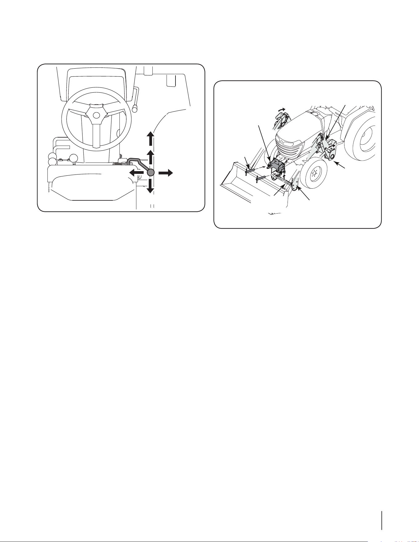
Mounting
Pin
Front Mount
Receiver
LH Mount
LH Mast
Support
Plate
Loader Hitch
Bracket
Figure 9
13
• Route the hydraulic hoses forward along the inside of the RH
loader hitch arm and place the hoses between the loader arm
and the hook of the hose retainer rod; then loop the hoses
rearward and place the hoses between the RH loader mast
and the second hose retaining rod. Refer to Figure 10.
Hose Retainer Rod
Figure 10
• Using the hydraulic control lever, fully cycle all cylinders
several times to purge air from the hydraulic system. After air
has been purged from system, roll the bucket back and lower
to the ground.
• Check the tractor’s transmission oil level as instructed in trac-
tor Operator’s Manual. Refill the transmission to the full mark
before operating the tractor and/or the loader. When adding oil
to the tractor transmission, always use the type of oil specified
for the tractor. NEVER MIX OIL TYPES.
SECTION 9: DISMOUNTING AND MOUNTING THE LOADER
DISMOUNTING THE LOADER
WARNING! A stored loader can fall and cause
serious injury or death. Securely store loader and
attachments on a hard level surface to prevent falling.
WARNING! To provide necessary balance, the loader
bucket must be installed before attaching or detaching
from tractor, or when loader is in stored position.
NOTE: the bucket must be installed to remove and re-mount the
loader.
Move the tractor and loader to a firm, level storage site.
• Using the implement control lever, level the bucket and lower it
to the ground to take the weight off the mounting pins secur-
ing the loader hitch bracket in the front mount receiver. Set the
tractor’s parking brake.
• Withdraw the two mounting pins that secure the loader hitch
bracket in the front receiver. Refer to Figure 9.
• Carefully use the control lever to raise the boom and lower the
loader hitch bracket out of the front receiver.
• Continue raising the boom until center points of the support
plates on the bottom of the loader hitch bracket are resting
on the ground, the loader hitch arms and bucket are support-
ing the weight of the loader, and the bottom of the RH and
LH masts have lifted off the tubular bars of the RH and LH
mounts. Refer to Figure 9.
• Stop the tractor engine and engage the parking brake.
• Disconnect the loader hoses from the tractor’s hydraulic
couplers by pushing inward the locking collar on each female
coupler of the tractor. Leave the hoses in the hose retainer rod.
• Re-install the protective plugs in the tractor’s hydraulic
couplers, and push the protective caps onto the male couplers
of the loader hoses.
• Re-start the tractor and carefully back the tractor away from
the front loader.
• Re-install the mounting pins in the front mount receiver and
secure with the two lynch pins.
WARNING! Do not climb or lean on the loader while
it’s in a stored position. Keep children and bystanders
away from the stored loader.
MOUNTING THE LOADER
With completion of the initial installation and operation, all loader
cylinders should be filled with hydraulic oil and should maintain the
position of the boom and mast when dismounted.
NOTE: if the loader is in storage for an extended period of time,
it may become necessary to again raise the base of the masts to
re-mount the loader. if this occurs, drive the tractor along the right
side of the loader, connect the loader hoses, and use the control
lever to raise the masts as described in “Pre-Charging Cylinders
for Initial Installation” earlier in this manual.
Mount the loader as follows:
14

• Start the tractor; then carefully drive the tractor between the
masts, loader hitch arms, and boom assembly. Slowly drive
the tractor forward while guiding the base of each mast into the
RH and LH mounts.
• Stop the tractor engine and engage the parking brake.
• Remove the two lynch pins and withdraw the mounting pins
from the front mount receiver. Refer to Figure 9.
• Using the color coded plugs and matching color coded wash-
ers on the loader hoses to guide you, remove the plugs and
connect each loader hose to the appropriate hydraulic coupler.
• Re-start the tractor engine.
• While observing the base of the masts, slowly push the
implement control lever forward to lower the boom and to the
right to dump the bucket. Drive the tractor forward (as needed)
to settle the masts onto the tubular bars of the RH and LH
mounts.
• When the masts are firmly settled into the RH and LH mounts,
continue to slowly push the control lever forward, and/or to
the right, to raise the loader hitch bracket upward into the
front mount receiver. As the hitch bracket is raised, the boom
cylinder pivot pins should also rotate back into the notches
of the RH and LH mounts. Refer to Figure 9. Drive the tractor
forward as necessary.
• When the loader hitch bracket is fully up inside the front mount
receiver, re-insert the two mounting pins removed earlier.
Secure the mounting pins with the two lynch pins.
• Place the hydraulic hoses in the hose retainer rod on the RH
loader hitch arm if not already in the retainer.
• Use the implement control lever to raise the bucket off the
ground.
SECTION 10: OPERATION
PRE-OPERATION CHECK LIST
(OPERATOR’S RESPONSIBILITy)
The operator should perform the following check list before
operating loader.
• Review and follow all safety rules and safety labels on pages 3
through 5.
• Check that all safety labels are installed and in good condition.
Replace if damaged.
• Check that equipment is properly and securely attached to
tractor, and that the bucket is securely attached to the loader
using the pins and retaining hardware supplied. Check that
all hardware (including all screws, nuts and pins) are properly
installed and secured.
• Check all lubrication points and grease as instructed on Page
23 of this manual.
• Check that all hydraulic hoses and fittings are in good condi-
tion and not leaking before starting tractor. Check that hoses
are not twisted, bent sharply, kinked, frayed or pulled tight.
Replace any damaged hoses immediately.
• Make sure tractor ROPS and seat belt are in good condition.
Never operate the loader without the tractor ROPS installed
and in the up position, and the seat belt securely fastened
around you lap.
• Do NOT allow riders.
TRACTOR BALLAST
If installing only the front loader (without the backhoe), weight must
be added to the rear of the tractor. The most common methods
of adding weight are mounting the rear weight box (Mod. No.
59A40013727) and/or filling the rear wheels with liquid ballast.
Rear Weight Box
Requires a minimum total weight of 500 pounds in a rear weight
box, with the center of gravity of the weight positioned approxi-
mately 41” from the center of rear axle and 20” above ground. If the
weight box is positioned closer to the rear axle or carried higher,
additional weight must be added to effectively counterbalance the
front loader.
Liquid Ballast
A water solution of calcium chloride may be used as liquid ballast in
each rear tire. Refer to the tractor operator’s manual for information
on adding liquid ballast to the rear tires. Liquid ballast alone may
not provide adequate counterbalance to the front loader.
Because special equipment and a familiarity with the practice is
required, only a qualified tire technician should perform this pro-
cedure. Consult with your Cub Cadet Yanmar dealer about having
liquid ballast added to your tires, and for any special maintenance
instructions after the procedure is performed.
15
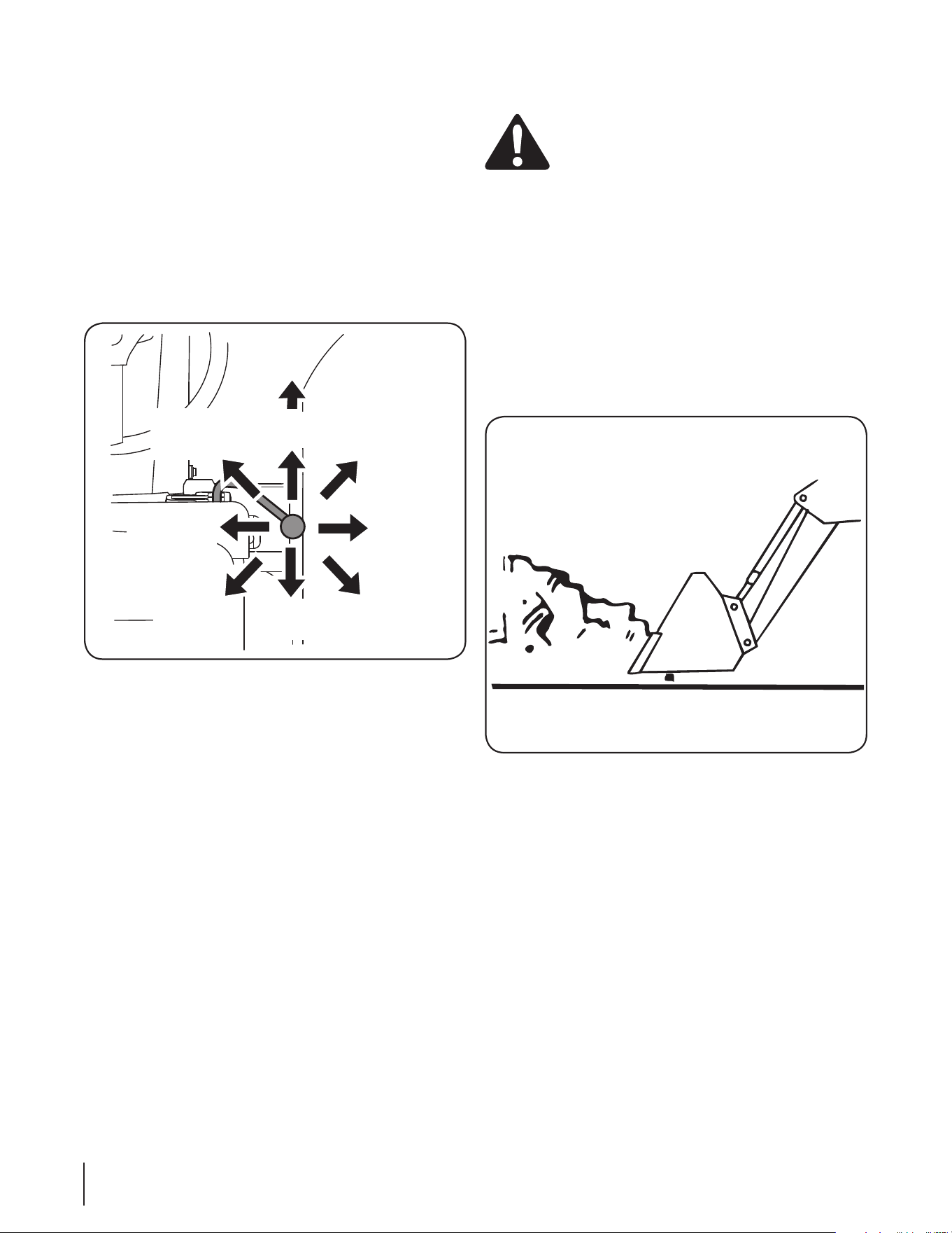
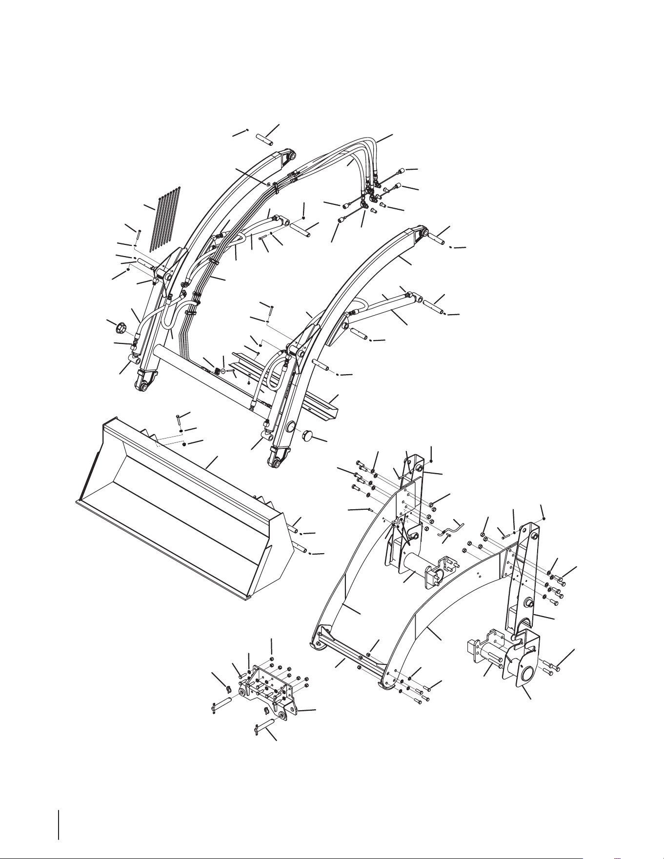
USING IMPLEMENT CONTROL LEvER
The tractor’s implement control lever is located at the front/right
corner of the operator’s seat and is used to control the movements
of the loader. All implement control lever movements should result
in the loader movements described below. If loader movements do
not respond correctly, turn the tractor’s engine off, set the parking
brake and recheck all hydraulic connections as described in “Pre-
Charging Cylinders for Initial Installation” in the “Initial Installation”
section earlier in this manual.
While seated in the operator’s seat of the tractor, use the imple-
ment control lever to control the loader movements as follows
(Refer to Figure 11):
• Move the control lever rearward to raise the loader boom.
• Move the control lever to the right to dump bucket.
• Move the control lever to the left to roll back bucket.
• Move the control lever rearward and to the right to raise the
boom and dump the bucket.
• Move the control lever rearward and to the left to raise the
boom and roll back the bucket.
• Move the control lever forward to lower the loader boom.
• Move the control lever forward and to the right to lower the
boom and dump the bucket.
• Move the control lever forward and to the left to lower the
boom and roll back the bucket.
• Move the control lever fully forward past the detent to place the
boom in the float position. The boom will float and allow the
bucket will follow the contour of the ground. The bucket control
cannot be used when the lever is in the float position.
OPERATING THE LOADER
WARNING! Do not operate unless all control lever
positions function as instructed in Figure 10.
The loader should be operated with the tractor engine running at
a safe RPM. Excessive speeds are dangerous, and may cause
bucket spillage and unnecessary strain on the tractor and loader.
NOTE: To prevent possible damage to the tractor trans-
mission, engage the 4WD only when additional traction
is needed while operating in loose soil or on slippery
surfaces, or when descending a slope. Disengage the
4WD when operating on firm, flat surfaces or when
operating at high speeds. Refer to the tractor operator’s
manual for instructions on using the 4WD feature.
• Approach and enter the pile with a level bucket.
See Figure 12.
Dump
Bucket
Boom
Float
Boom
Raise
Roll Back
Bucket
Lower
Boom
Raise/
Dump
Raise/
Roll Back
Lower/
Dump
Lower/
Roll Back
Figure 11
Figure 12
16
The lift and rollback of the bucket will increase efficiency because
maintaining a level bucket throughout the lifting cycle resists bucket
lift and increases breakaway effort. See Figure 13.
NOTE: Do not be concerned if the bucket is not com-
pletely filled during each pass. Maximum productivity is
determined by the amount of material loaded in a given
period of time. Time is lost if two or more attempts are
made to fill the bucket on each pass.
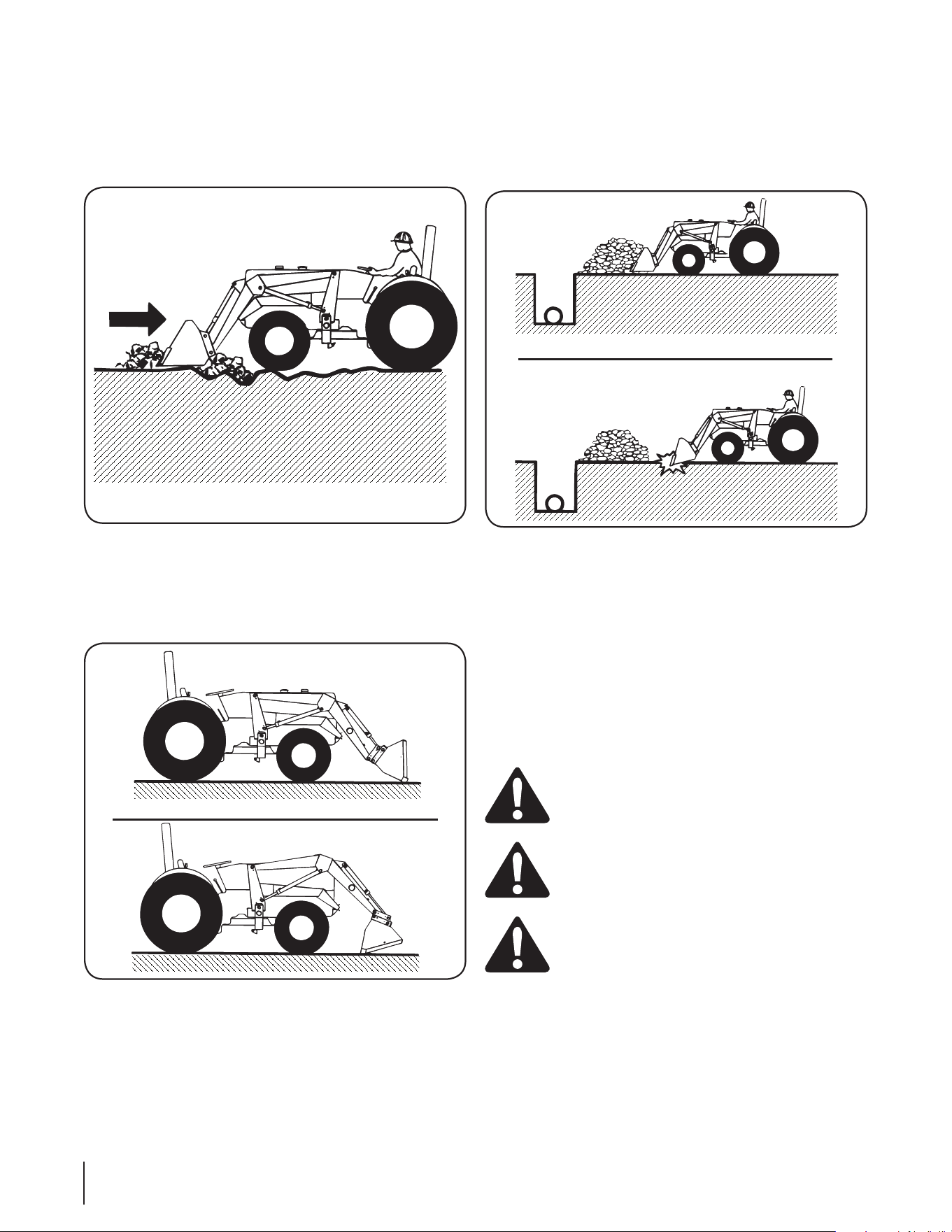
Lifting the Load
When lifting the load, keep the bucket positioned to avoid spillage.
See Figure 14.
WARNING! Do not attempt to lift bucket loads in
excess of the loader capacity.
Correct
NOT Correct
Figure 13
NOTE: If you should discover that your tractor requires
increased stability for a particular application, contact
your Cub Cadet Yanmar dealer about additional
weighting for the rear of the tractor.
Carrying the Load
Position the bucket below the level of the tractor hood for maximum
stability and visibility, whether the bucket is loaded or empty. See
Figure 15.
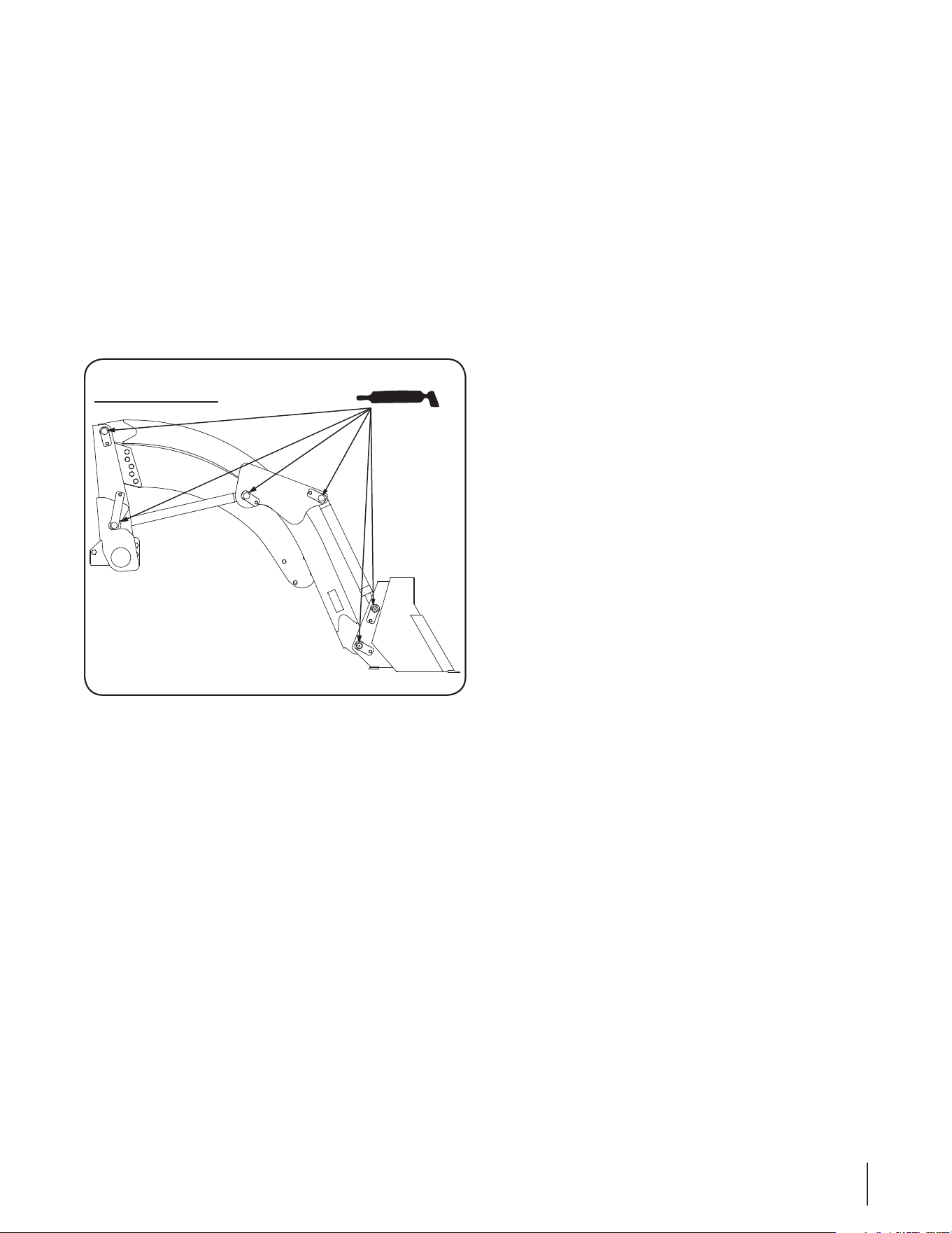
Use extreme care when operating the loader on a slope; keep the
bucket as low as possible. This keeps the bucket and tractor center
of gravity low and will provide maximum tractor stability. See Figure
17.
Figure 14
Figure 15
Correct
NOT Correct
Figure 16
17
WARNING! Avoid injury or death from rollover
accidents:
• Move and turn tractor at low speeds.
• Watch for hidden hazards such as holes,
ditches, and other obstructions which may cause
tractor and loader to tip over.
• Carry loads close to the ground to aid visibility
and lower center of gravity for improved stability.
• Balance loads so weight is evenly distributed
and load is stable.
• Be extra careful when operating on a slope.
• Do not operate on steep slopes.
• Do not stop, start or change directions sud-
denly on slopes.
• Tractor seat belt and Roll-Over Protective
Structure (ROPS) must be present. Keep seat belt
securely fastened and keep ROPS systems in “up”
position at all times.
NOTE: When transporting the load, keep the bucket as
low as possible to avoid tipping, in case a wheel drops
in a rut. Refer to Figure 16.
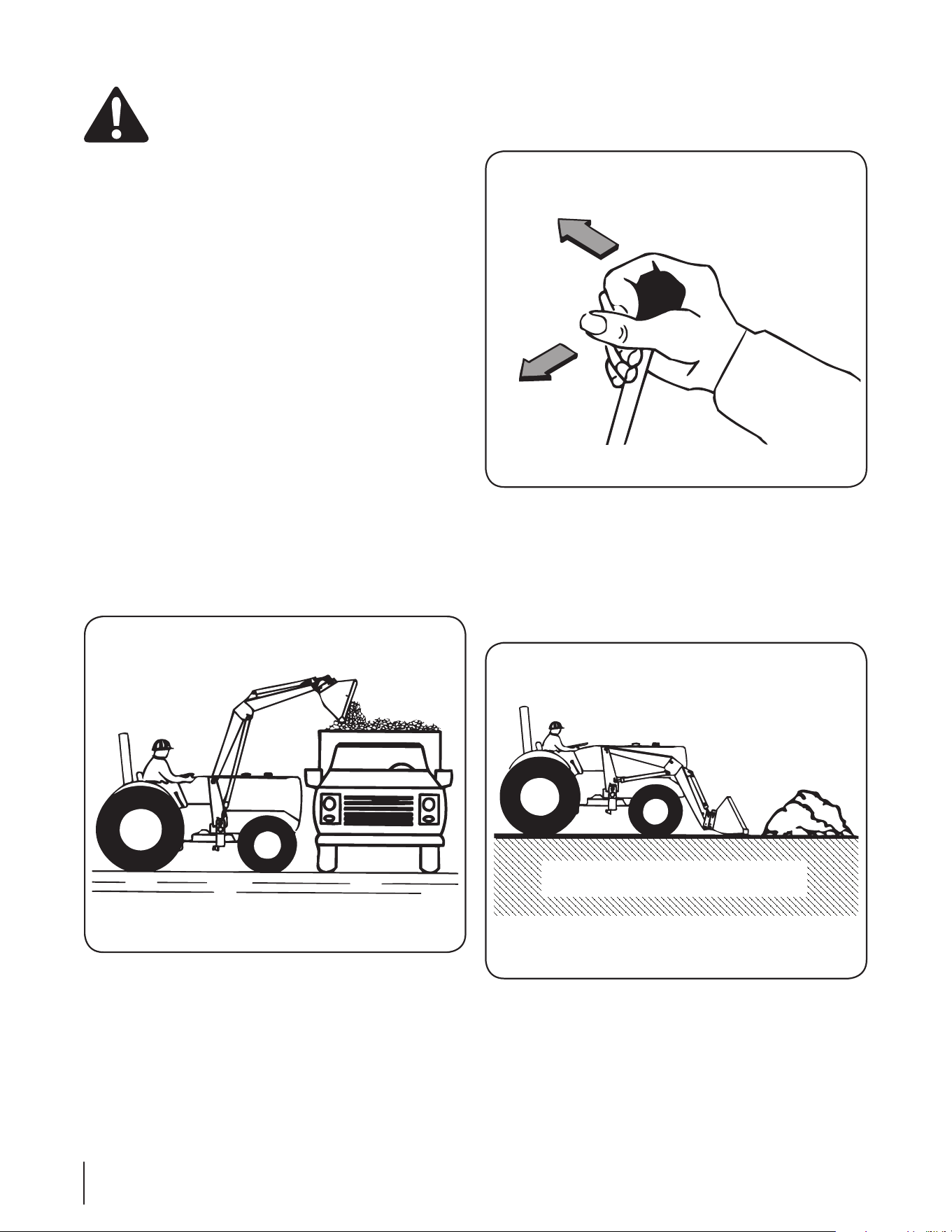
Dumping the Bucket
Lift the bucket high enough to clear the side of the vehicle. Move
the tractor in as close as possible, then dump the bucket. See
Figure 17.
Lowering the Bucket
After the bucket is dumped, back away from the vehicle while
lowering and rolling back the bucket. See Figure 18.
Operating with a Float Control
During hard surface operation, keep the bucket level and put the lift
control in the float position to permit the bucket to float on the work-
ing surface. If hydraulic down pressure is exerted on the bucket, it
will wear faster than normal. See Figure 19.
NOTE: The float will also prevent the mixing of surface
material with stockpile material. The float position will
reduce the chance of surface gouging when removing
snow or other material.
Figure 17
Roll Back
Lower
Figure 18
Surface Material
Figure 19
18
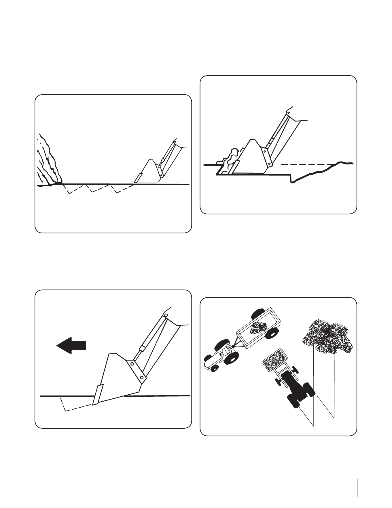
Loading from a Bank
Exercise caution when undercutting high banks. Dirt slides can be
dangerous. Load from as low as possible for maximum efficiency.
Loader lift and break-away capacity diminish as loading height is
increased.
It’s important to keep the bucket level when approaching a bank or
pile. This will help prevent gouging in the work area. See Figure 20.
Peeling and Scraping
Use a slight bucket angle, travel forward, and hold the lift control
forward to start the cut. Make a five- to eight-inch angle cut and
break-out cleanly. See Figure 21.
With the bucket level, start a cut at the notch approximately four
inches deep. Hold the depth by feathering the bucket control to
adjust the cutting lip up or down. When the front tires enter the
notch, adjust the lift cylinder to maintain proper depth. See Figure
22.
Make additional passes until the desired depth is reached. During
each pass, only use the bucket control while at working depth.
This will allow you to concentrate on controlling the bucket angle to
maintain a precise cut.
Loading Low Trucks or Spreaders from a Pile
For easier loading, minimize the angle of turn and length of run
between pile and spreader. See Figure 23.
Figure 20
Figure 21
Figure 22
Figure 23
19
Backgrading
Backgrade occasionally with a loaded bucket to keep the working
surface free of ruts and holes. Also, hold the control lever forward
so the full weight of the bucket is scraping the ground. Use the heel
of the bucket. See Figure 24.
Backblading
Position the bucket at an angle of less than 45º and backup slowly.
See Figure 25.
Backgrading or backblading with bucket tilted too far will result in
damage to tilt cylinders and void warranty. See Figure 25.
Backfilling
Approach the pile with a flat bucket. Do not use the bucket in the
dump position for bulldozing. This method will impose severe
shock loadings on the dump linkage, the tilt cylinder, and the
tractor. Refer to Figure 26.
• Leave dirt in the bucket because dumping on each pass
wastes time.
• Operate at right angles to the ditch. Take as big a bite as the
tractor can handle without lugging down.
• Leave dirt which drifts over the side of the bucket for final
clean-up.
• Pile dirt on the high side for easier backfilling on a slope.
Handling Objects
WARNING! Avoid injury or death from falling objects.
This loader is not equipped with any method to
prevent objects such as round bales, posts, logs, etc.
from rolling back onto operator.
WARNING! Do not carry large objects that can fall out
of loader bucket into operator zone.
WARNING! Never lift loader higher than necessary to
clear the ground when moving.
Figure 24
Correct
NOT Correct
Correct
NOT Correct
Figure 26
20
SECTION 11: MAINTENANCE
LUBRICATION
Daily
• Check the level of hydraulic oil in tractor before starting each
day’s operation. If necessary, add oil as recommended in your
tractor owner’s manual.
NOTE: When adding oil to the tractor reservoir, always
use hydraulic oil as specified in the tractor operator’s
manual.
• Lubricate after every eight hours of operation (See Figure 27):
- Apply lubrication to the grease fitting in the hub at the mast
end (rearward end) of each boom arm.
- Apply lubrication to the grease fittings at the each end of
both boom lift cylinders.
- Apply lubrication to the grease fitting in the hub at the upper
end of each bucket cylinder.
- Apply lubrication to the grease fittings in the outer end of all
four pivot pins of the loader bucket.
GENERAL MAINTENANCE
After every eight hours of operation, check all hardware and tighten
where required.
Replace hoses immediately if they are damaged by a cut or scrape,
extruded at the fittings, or leaking. Hydraulic oil leaks should be
repaired promptly to avoid loss of oil and serious personal injury
from escaping oil.
LUBRICATION
Figure 27
21

SECTION 12: TROUBLESHOOTING
PROBLEM POSSIBLE CAUSE SOLUTION
Jerky Operation
• Air in hydraulic system
• Cold hydraulic oil
• Low hydraulic oil level
• Poor oil circulation
• Worn or damaged hydraulic pump
• Air leak in pump inlet line
• Cycle cylinders several times to purge
system of air.
• Run engine to warm oil.
• Add oil to level specified.
• Change oil filter and clean screen in
tractor hydraulic system.
• Repair or replace pump.
• Check, tighten or replace inlet line.
Slow Operation
• Faulty valve
• Air in hydraulic system
• Hydraulic oil too heavy
• Oil filter plugged
• Slow engine speed
• Cylinder piston seals leaking
• Valve out of adjustment or malfunctioning
• Tractor hydraulic pump malfunctioning
• Hydraulic couplers not completely engaged
• Repair or replace valve.
• Cycle lift cylinders and bucket
cylinders several times to free system
from air.
• Change to proper oil.
• Clean and replace filter.
• Increase engine speed rate.
• Repair (if available) or replace
• Adjust, repair or replace.
• Repair or replace pump.
• Connect hydraulic couplers.
Oil Leaks
• Loose hose connections
• Fittings or hoses defective
• Hydraulic cylinder seals worn or damaged
• Valve components worn or damaged
• Tighten fittings.
• Use thread sealer on pipe (tapered)
threads.
• Repair seals (if available) or replace
cylinder.
• Repair and/or replace.
Cannot Raise Load
• Low oil supply
• Bucket overloaded
• Hose fittings not fully engaged in couplers
• Cylinder piston seal leakage
• Valve out of adjustment or malfunctioning
• Hydraulic pump malfunctioning
• Load is greater than boom lift capacity
• Check oil level.
• Try lighter load.
• Recouple hoses.
• Repair or replace.
• Repair or replace.
• Repair or replace.
• Check loader specifications.
22

PROBLEM POSSIBLE CAUSE SOLUTION
Bucket or Boom Leaks
Down from “Hold”
Position
• Leaks in hydraulic circuits
• Cylinder piston seals leaking
• Remote valve worn or damaged
• Tractor valve worn or damaged
• Tighten loose fittings. Use thread
sealer on pipe threads.
• Repair (if available) or replace.
• Repair.
• Repair.
Cannot Lower Boom
• Hydraulic couplers not fully engaged. • Recouple hoses.
Loss of Bucket Tilt
Control When Lever
is Pushed Completely
Forward
• Tractor lever in “Float” position • Shift control lever from “Float” posi-
tion.
Couplers Hard
to Hook Up
• Pressure in circuit • Place control levers in “Float” when
connecting.
Boom & Bucket
Operation Does Not
Correspond To Control
Lever Position
• Improperly installed hydraulic couplers
• Hoses improperly connected
• Install hydraulic couplers correctly.
• Connect hoses properly.
Excessive Wear on
Bucket Cutting Edge
and Wear Pads
• Bucket is tilted too far forward and is riding on cutting
edge.
• Excessive down pressure when cleaning feedlots
and working on concrete.
• Keep bottom of bucket parallel to
ground.
• Use “Float” position on boom lift
control lever.
23
SECTION 13: PARTS LIST
45
45
47
21
35
34
23
24
45
14
40
28
41
9
33
38
39
39
21
47
32
47
21
36
47
28
47
42
29
7
24
45
14
41
14
45
24
19
18
44
31
41
48
48
24
21
47
45
14
42
48
29
41
10
41
48
40
1
46
17
13
50
24
13
5
3
2
12
11
26
6
43
20
27
22
26
43
20
16
15
4
50
25
25
14
24
14
24
46
17
47
47
21
49
8
30
24

Ref. Part Number Description
1
603-04623A Arm Assembly, Main
2
603-04624 Support Assembly, Vertical, LH
3
603-04625 Support Assembly, Vertical, RH
4
603-04626 Mount Assembly, LH
5
603-04627 Mount Assembly, RH
6
603-04629 Receptacle Assembly, Loader
7
603-04636 Bracket Assembly, Loader
8
603-04641 Bracket Assembly, Hitch Loader
9
627-00001 Tube Assembly, Loader
10
703-06857 Cover, Tube, Loader
11
703-07143 Bracket, Loader, RH
12
703-07145 Bracket, Loader, LH
13
710-0376 Hex Screw, 5/16-18, 1.00, Gr5
14
710-0395 Hex Screw, 5/16-18, 2.25, Gr5
15
710-04700 Screw, M16-20, 60mm
16
710-04701 Screw, M16-2.00, 100mm
17
710-04706 Hex Screw, 5/8-11, 1.75, Gr8
18
710 -112 2 Hex Screw, 1/4-20, 2.50, Gr5
19
710-1652 Screw, Self-tapping 1/4-20 x .625
20
710-3067 Hex Screw, 1/2-13, 1.75, Gr5
21
711-05018 Pin, 1”OD, 5”, Grease, w/ 5/16” Hole
22
711-05034B Pin, 1”OD, w/ Handle
23
711 - 0519 4 Pin, 1”OD, 6.5”, Grease, 5/16” Hole
24
712-04063 Nut, Flange Lock, 5/16-18, GrF,
25
712-04143 Nut, Flange, 5/8-11 Top Lock
Ref. Part Number Description
26
712-3083 Nut, Hex Lock, 1/2-13, GrB, Nylon
27
714-0143 Pin, Klik, .245 Dia X 1.406
28
717- 04 625 Cylinder, 28”, 1.625” Bore
29
717-04626 Cylinder, 24”, 2” Bore
30
726-0233 Nut, Push, .25 Id X .50 OD
31
726-04081 Clamp, Tube
32 726-04098 Cable Tie, 18”
33
727- 04197 Plug, Female, Hydr’ Coupler, Green
34
727- 04198 Plug, Female, Hydr’ Coupler, Blue
35
727- 04199 Plug, Female, Hydr’ Coupler, Yellow
36
727-04200 Plug, Female, Hydr’ Coupler, Red
38
727-04259 Coupling, Hydraulic, Male Sae, 3/8
39
727-04332 Hose, Hydr’, 1/2 ORB, 3/8 ORFS
40
727-04333 Hose, Hydr’, 3/8 ORFS-3/8 ORFS 90
41
727-04334 Hose, Hydr’, 3/8 ORFS-3/8 ORFS 90
42
731-06405 Plug, Tube, Round
43
736-0192 Washer, Flat, .535x.930x.090
44
73 6 - 0 211 Washer, Flat, .285 X 1.25 X .06
45
736-0264 Washer, Flat, .330 x .630 x .064
46
736-0366 Washer, Flat, .640x1.120x.125
47
737-0146 Grease Fitting
48
737-04186A Fitting, Straight, 3/8 ORFS X 3/8 ORB
49
737-04229 Fitting, Hydr’, 90, -8 ORB X -8 FORB
50
747-04753 Rod, Hook
— 727- 04213A Hose Sleeve
25

NOTES
26

GDOC-100101 REV. E
Cub Cadet yanmar LLC, P.O. BOX 361052 CLEvELAND, OHIO 44136-1052; Phone: 1-877-926-6271
MANUFACTURER’S LIMITED WARRANTy FOR
Thank you for purchasing a Cub Cadet Yanmar! Cub Cadet Yanmar
prides itself on delivering a durable, quality, and reliable product to
you our customer. This is a comprehensive warranty provided to you
at no extra charge. Please take a moment to become familiar with
the Product Warranty. It contains the information you will need to
have your Cub Cadet Yanmar repaired in the unlikely occurrence that
a failure would occur. Please record your tractor and/or attachment
model, serial number and date of purchase for each item. We know
you will enjoy your purchase of a Cub Cadet Yanmar product and we
thank you again!
IMPORTANT: To obtain warranty coverage owner must present proof
of purchase and applicable maintenance records to the servicing
dealer. Please see the operator’s manual for information on required
maintenance and service intervals. The limited warranty set forth
below is provided by Cub Cadet Yanmar LLC with respect to new
merchandise purchased or leased and used in the United States and/
or its territories and possessions, and by MTD Products Limited with
respect to new merchandise purchased or leased and used in Canada
and/or its territories and possessions (either entity respectively, “Cub
Cadet Yanmar”).
Warranty Coverage— Cub Cadet Yanmar warrants all product
components except Wear Items, Batteries, Powertrain Components,
Attachments, Engine Electrical Parts, Engine Emissions Control
Systems, Tires and Service Parts (the “Specific Warranty
Components”) against defects in material and workmanship for a
period of two (2) years or two thousand (2000) operation hours,
whichever comes first. Specific Warranty Components are covered
for the warranty periods specifically described for those components
below. All warranty periods commence on the date of original retail
purchase or lease. Cub Cadet Yanmar will, at its option, repair or
replace, free of charge, any part found to be defective in materials
or workmanship during the applicable warranty periods described
herein.
The original retail purchaser can transfer this Limited Warranty
to a subsequent purchaser or owner at any time during the initial
Warranty Period. The subsequent purchaser’s warranty period is
only the balance of the initial Warranty Period remaining at the time
of transfer. In order to transfer warranty coverage, the subsequent
owner must provide Cub Cadet Yanmar with written notice of any
such transfer including unit model and serial numbers.
Warranty Coverage
Compact Utility Tractor 24 months / 2000 Hours
Tractor Powertrain 36 months / 2000 Hours
Tractor Attachments 12 months
Wear Items are warranted to be free from defects in material and
workmanship for a period of ninety (90) days from the date of original
purchase or lease. Wear items include: lamp bulbs, wiper blades,
injection nozzles, spark plugs, glow plugs, strainers, fuses, brake
linings, clutch facings, clutch discs, coolant, rubber products, glass
products, plastic products, packings, belts and hoses.
Batteries have a one-year prorated limited warranty against defects
in material and workmanship, with 100% replacement during the
first three months. After three months, the battery replacement
credit is based on the months remaining in the twelve (12) month
period dating back to the original date of original sale or lease. Any
replacement battery will be warranted only for the remainder of the
original warranty period.
Powertrain — Cub Cadet Yanmar warrants components found in the
engine and driveline (excluding any other any other Specific Warranty
Components enumerated herein) for three (3) years or two thousand
(2000) operation hours, whichever comes first. Cub Cadet Yanmar
will, at its option, repair or replace, free of charge, any Powertrain
component found to be defective in materials or workmanship while
under warranty. Powertrain components include items such as the
cylinder block, cylinder head, valve covers, oil pan, timing gear
covers, flywheel housing, hydrostatic transmission, transmission
case, differential and rear axle housings, clutch housings, front axle
assembly, and all parts contained therein. Powertrain components
do not include the fuel systems, cooling systems, intake and exhaust
components or external drivelines, clutch disks, or steering cylinders
which are covered under the other applicable warranties described
herein.
Attachments — Cub Cadet Yanmar warrants its approved attachments
against defects in material and workmanship for a period of one (1)
year, commencing on the date of the attachment’s original purchase
or lease. Attachments include, but are not limited to items such as:
Mowing Decks, Loaders and Backhoes. The Warranty Term applicable
to the Loader and Backhoe for the Sc2450 is one (1) year on the
loader and backhoe
Engine Electrical Parts — The Warranty for Products for engine
electrical Parts (to the extent incorporated in and sold as an integral
component of a Product as opposed to an individual Part) shall
expire upon twelve (12) months or one thousand (1000) hours of
use, whichever comes first,commencing on the date of the product’s
original purchase or lease.

Engine Emissions Control System — EPA Limited Warranty for
PRODUCT. The warranty period for components of the Engine
Emissions Control System of the PRODUCT, including the injection
pump, fuel injection nozzle and turbocharger shall commence on the
date of delivery to the original retail purchaser from an authorized Cub
Cadet Yanmar Dealer and shall continue for a period as below.
Maximum power is Its warranty period is
kW<19 (PS<25.8) 1,500 hours or two years,
whichever comes first.
19≤kW<37 (25.8≤PS<50.3) 3,000 hours or five years,
whichever comes first.
Tires are warranted to be free from defects in material and
workmanship for a period of twelve (12) months from the date of
original purchase or lease
Service Parts — The Warranty for Service Parts shall expire ninety
(90) days from the date of purchase. However, if the part is installed
on a unit which has more than 90 days remaining on the original
warranty, the part is warranted for the remaining time on any of the
applicable warranty periods for that component.
The remedies described in this limited warranty shall only be available
if the product has been operated and maintained in accordance with
the Operator’s Manual furnished with the product, and the product
has not been subject to misuse, abuse, neglect, accident, improper
maintenance, alteration, vandalism, theft, fire, water, or damage
because of other peril or natural disaster. Damage resulting from the
installation or use of any part, accessory or attachment not approved
by Cub Cadet Yanmar for use with the product(s) will void your
warranty as to any resulting damage. In addition, Cub Cadet Yanmar
may deny warranty coverage if the hour meter, or any part thereof, is
altered, modified, disconnected or otherwise tampered with.
HOW TO OBTAIN SERVICE: Warranty service is available, WITH
PROOF OF PURCHASE AND APPLICABLE MAINTENANCE RECORDS,
through your local authorized service dealer. To locate the dealer in
your area:
In the U.S.A.:
Check your Yellow Pages, or contact Cub Cadet Yanmar LLC at P.O.
Box 361052, Cleveland, Ohio 44136-1052, call 1-877-282-5055
or log on to our website at www.cubcadetyanmar.com.
In Canada:
For all provinces excluding Quebec contact Modern Power Products
c/o MTD Canada Ltd. at 60 Ottawa Street South, Kitchner, Ontario
N2G 3S7, call 1-800-567-6775 or log on to our website at
www.cubcadet.ca.
In Quebec contact Les Distributions RM Ltee. c/o MTD Canada Ltd.
2955 Jean-Baptiste Deschamps, Ville Lachine, Quebec HBT 1C5,
call 1-800-361-5770 or log on to our website at www.rvi.qc.ca
MANUFACTURER’S LIMITED WARRANTy (CONT’D)
Cub Cadet yanmar LLC, P.O. BOX 361052 CLEvELAND, OHIO 44136-1052; Phone: 1-877-926-6271
Without limiting the foregoing, this limited warranty does not provide
coverage in the following cases:
a. Routine maintenance and related items such as lubricants, filters
(oil, fuel, air and hydraulic), cleaning, tune-ups, brake and/or
clutch inspection, adjustments made as part of normal mainte-
nance, blade sharpening, set-up, abuse, accident and/or normal
wear. It does not cover incidental costs such as transporting your
equipment to and from the dealer, telephone charges or renting a
product temporarily to replace a warranted product.
b. Service completed by someone other than an authorized service
dealer.
c. Cub Cadet Yanmar does not extend any warranty for products sold
or exported outside of the United States and/or Canada, and their
respective possessions and territories.
d. Replacement parts and/or accessories that are not genuine Cub
Cadet Yanmar parts.
e. Transportation charges and dealer off-site service calls..
There are no implied warranties including without limitation any
implied warranty of merchantability or fitness for a particular
purpose. No warranties shall apply after the applicable period
of express written warranty above. No other express warranties
beyond those mentioned above, given by any person or entity,
including a dealer or retailer, with respect to any product, shall
bind Cub Cadet Yanmar. The exclusive remedy is repair or
replacement of the product as set forth above. The terms of this
warranty provide the sole and exclusive remedy arising from
the sale and/or lease of the products covered hereby. Cub Cadet
Yanmar shall not be liable for any incidental or consequential
loss or damage including, without limitation, expenses incurred
for substitute or replacement lawn care services or for rental
expenses to temporarily replace a warranted product.
Some jurisdictions do not allow the exclusion or limitation of
incidental or consequential damages, or limitations on how long an
implied warranty lasts, so the above exclusions or limitations may not
apply to you.
In no event shall recovery of any kind be greater than the amount of
the purchase price of the product sold. Alteration of safety features of
the product shall void this warranty. You assume the risk and liability
for loss, damage, or injury to you and your property and/or to others
and their property arising out of the misuse or inability to use the
product.
This limited warranty shall not extend to anyone other than the
original lessee, purchaser or to the person for whom it was purchased
as a gift unless it is properly transferred in writing as described
above.
HOW LOCAL LAWS RELATE TO THIS WARRANTY: This limited
warranty gives you specific legal rights, and you may also have other
rights that vary in different jurisdictions.

