4
BULLt I IN NU.
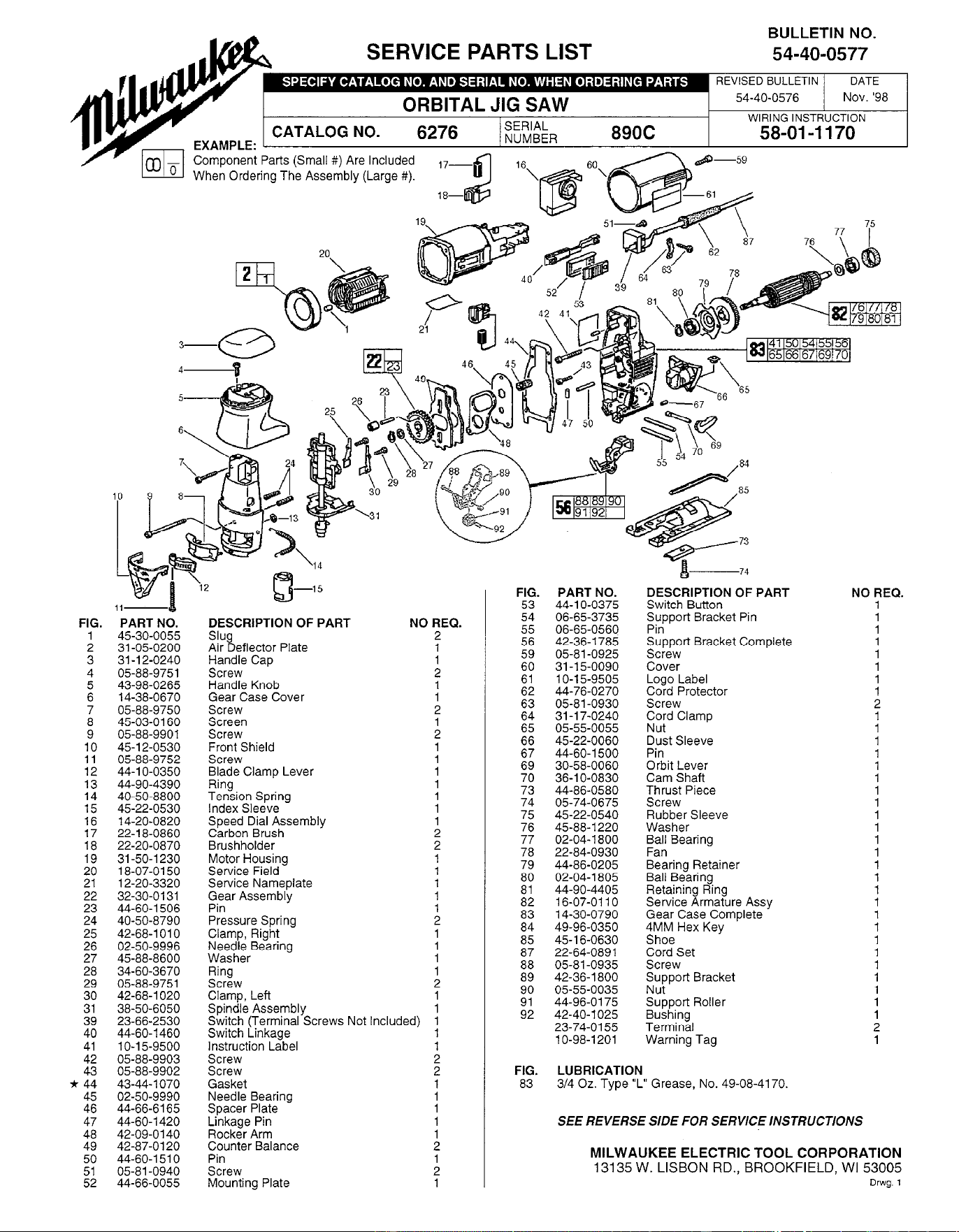
SERVICE PARTS LIST
54-40-0577
li-
PART NO.
45-30-0055
31-05-0200
31-l 2-0240
05-88-9751
43-98-0265
14-38-0670
05-88-9750
45-03-0160
05-88-9901
45-l 2-0530
05-88-9752
44-l O-0350
44-90-4390
40-50-8800
45-22-0530
14-20-0820
22-l 8-0860
22-20-0870
31-50-l 230
18-07-0150
12-20-3320
32-30-0131
44-60-l 506
40-50-8790
42-68-l 010
02-50-9996
45-88-8600
34-60-3670
05-88-9751
42-68-l 020
38-50-6050
23-66-2530
44-60-l 460
1 o-1 5-9500
05-88-9903
05-88-9902
43-44-l 070
02-50-9990
44-66-6165
44-60-1420
42-09-0140
42-87-0120
44-60-l 510
05-81-0940
44-66-0055
REVISED BULLETIN
DATE
54-40-0576
Nov. ‘98
IH VT\..
CATALOG NO.
6276
SERIAL
WIRING INSTRUCTION
NUMBER
890C
58-01-1170
EXAMPLE:
- ^
_^
DESCRIPTION OF PART
Slug
Air Deflector Plate
Handle Cap
Screw
Handle Knob
Gear Case Cover
Screw
Screen
Screw
Front Shield
Screw
Blade Clamp Lever
Ring
Tension Spring
Index Sleeve
NO REQ.
2
1
Speed Dial Assembly
Carbon Brush
:
Brushholder
2
Motor Housing
Service Field
:
Service Nameplate
1
;Fr Assembly
Pressure Spring
Clamp, Right
Needle Bearing
Washer
Ring
Screw
Clamp, Left
Spindle Assembly
Switch (Terminal Screws Not Included)
Switch Linkage
Instruction Label
Screw
Screw
;
Gasket
1
Needle Bearing
1
Spacer Plate
Linkage Pin
1
Rocker Arm
Counter Balance
Pin
Screw
Mounting Plate
2
:
1
PART NO.
44-l O-0375
06-65-3735
06-65-0560
42-36-l 785
05-81-0925
31-l 5-0090
1 o-1 5-9505
44-76-0270
05-81-0930
31-l 7-0240
05-55-0055
45-22-0060
44-60-l 500
30-58-0060
36-l O-0830
44-86-0580
05-74-0675
45-22-0540
45-88-l 220
02-04-l 800
22-84-0930
44-86-0205
02-04-l 805
44-90-4405
16-07-0110
14-30-0790
49-96-0350
45-16-0630
22-64-0891
05-81-0935
42-36-l 800
05-55-0035
44-96-0175
42-40-l 025
23-74-0155
1 O-98-1 201
DESCRIPTION OF PART
Switch Button
“,;pport Bracket Pin
Support Bracket Complete
Screw
Cover
Logo Label
Cord Protector
Screw
Cord Clamp
Nut
Dust Sleeve
Pin
;;b; l_;vaer
Thrust Piece
Screw
Rubber Sleeve
Washer
Ball Bearing
Fan
Bearing Retainer
Ball Bearing
Retaining Ring
Service Armature Assy
Gear Case Complete
4MM Hex Key
Shoe
Cord Set
Screw
Support Bracket
Nut
Support Roller
Bushing
Terminal
Warning Tag
LUBRICATION
314 Oz. Type “L” Grease, No. 49-08-4170.
NO REQ.
1
1
1
:
1
SEE REVERSE SIDE FOR SERVICE INSTRUCTIONS
MILWAUKEE ELECTRIC TOOL CORPORATION
13135 W. LISBON RD., BROOKFIELD, WI 53005
Drwg. 1
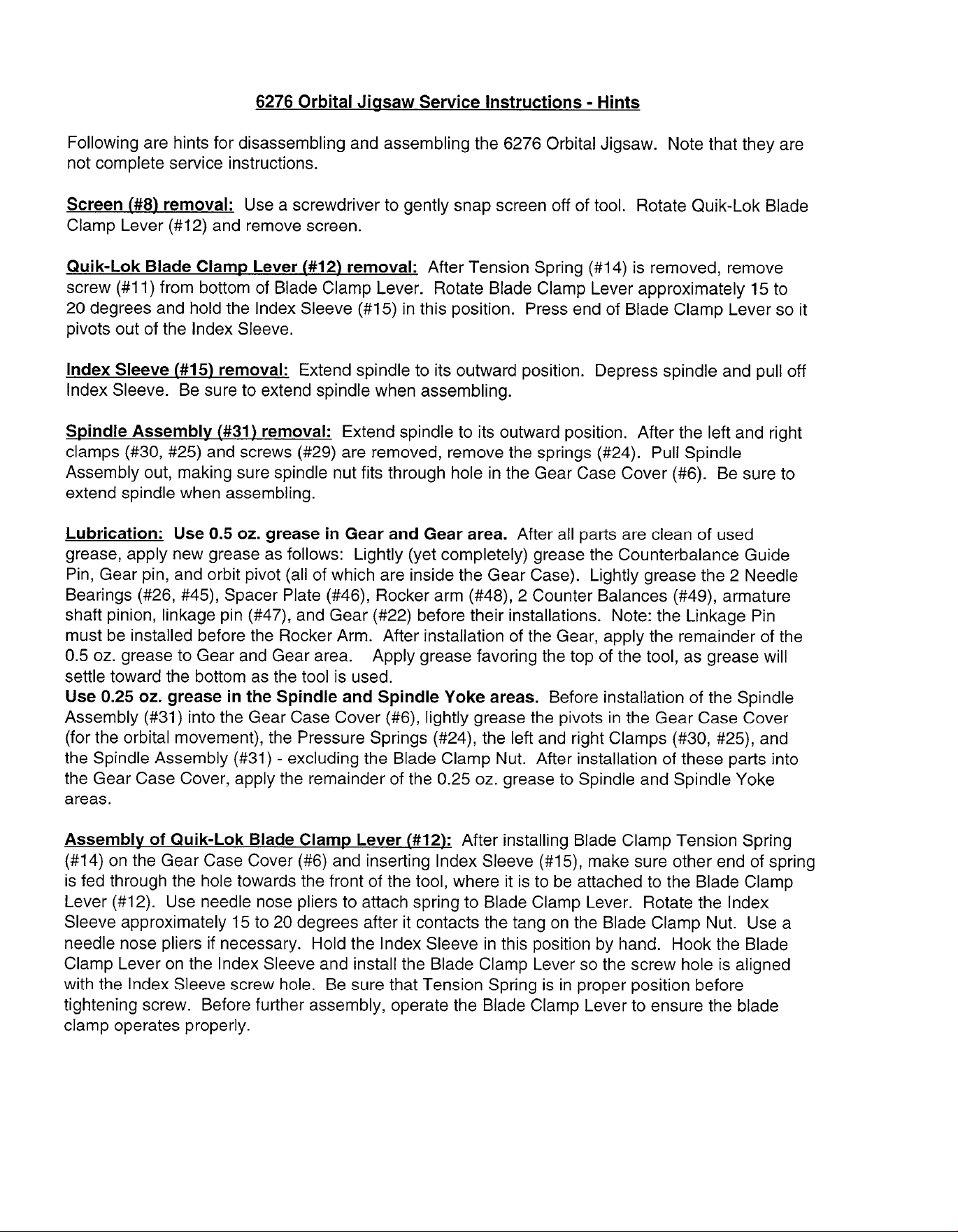
6276 Orbital Jiasaw Service Instructions - Hints
Following are hints for disassembling and assembling the 6276 Orbital Jigsaw. Note that they are
not complete service instructions.
Screen (#8) removal: Use a screwdriver to gently snap screen off of tool. Rotate Quik-Lok Blade
Clamp Lever (#12) and remove screen.
Quik-Lok Blade Clamp Lever (#12) removal: After Tension Spring (#14) is removed, remove
screw (#11) from bottom of Blade Clamp Lever. Rotate Blade Clamp Lever approximately 15 to
20 degrees and hold the Index Sleeve (#15) in this position. Press end of Blade Clamp Lever so it
pivots out of the Index Sleeve.
Index Sleeve (#15) removal: Extend spindle to its outward position. Depress spindle and pull off
Index Sleeve. Be sure to extend spindle when assembling.
Spindle Assembly (#31) removal: Extend spindle to its outward position. After the left and right
clamps (#30, #25) and screws (#29) are removed, remove the springs (#24). Pull Spindle
Assembly out, making sure spindle nut fits through hole in the Gear Case Cover (#6). Be sure to
extend spindle when assembling.
Lubrication: Use 0.5 oz. grease in Gear and Gear area. After all parts are clean of used
grease, apply new grease as follows: Lightly (yet completely) grease the Counterbalance Guide
Pin, Gear pin, and orbit pivot (all of which are inside the Gear Case). Lightly grease the 2 Needle
Bearings (#26, #45), Spacer Plate (#46), Rocker arm (#48), 2 Counter Balances (#49), armature
shaft pinion, linkage pin (#47), and Gear (#22) before their installations. Note: the Linkage Pin
must be installed before the Rocker Arm. After installation of the Gear, apply the remainder of the
0.5 oz. grease to Gear and Gear area. Apply grease favoring the top of the tool, as grease will
settle toward the bottom as the tool is used.
Use 0.25 oz. grease in the Spindle and Spindle Yoke areas. Before installation of the Spindle
Assembly (#31) into the Gear Case Cover (#6), lightly grease the pivots in the Gear Case Cover
(for the orbital movement), the Pressure Springs (#24), the left and right Clamps (#30, #25), and
the Spindle Assembly (#31) - excluding the Blade Clamp Nut. After installation of these parts into
the Gear Case Cover, apply the remainder of the 0.25 oz. grease to Spindle and Spindle Yoke
areas.
Assembly of Quik-Lok Blade Clamp Lever (#12): After installing Blade Clamp Tension Spring
(#14) on the Gear Case Cover (#6) and inserting Index Sleeve (#15), make sure other end of spring
is fed through the hole towards the front of the tool, where it is to be attached to the Blade Clamp
Lever (#12). Use needle nose pliers to attach spring to Blade Clamp Lever. Rotate the Index
Sleeve approximately 15 to 20 degrees after it contacts the tang on the Blade Clamp Nut. Use a
needle nose pliers if necessary. Hold the Index Sleeve in this position by hand. Hook the Blade
Clamp Lever on the Index Sleeve and install the Blade Clamp Lever so the screw hole is aligned
with the Index Sleeve screw hole. Be sure that Tension Spring is in proper position before
tightening screw. Before further assembly, operate the Blade Clamp Lever to ensure the blade
clamp operates properly.