C
o
v
e
r
User manual
Network cameras
Ver 1.017.000

Contents
1 Introduction ………………………………………………………………… 1
1.1 About User Manuals ………………………………………………………… 1
1.2 Compatible models and symbols in this manual ……………………………… 1
1.3 Abbreviation ………………………………………………………………… 12
1.4 Disclaimer …………………………………………………………………… 12
1.5 For trademarks and registered trademarks ………………………………… 13
1.6 NETWORK RELATIONSHIP ………………………………………………… 13
1.7 Instructions for use …………………………………………………………… 14
2 Operation …………………………………………………………………… 18
2.1 Initial Setting ………………………………………………………………… 18
2.2 Initial setting (Multi-directional/PTZ integrated camera) …………………… 23
2.3 Viewing images from a PC …………………………………………………… 28
2.3.1 View camera images ……………………………………………………… 29
2.3.2 About live image pages …………………………………………………… 49
2.3.3 Monitor images from multiple cameras …………………………………… 89
2.4 Viewing images from mobile/tablet terminals ……………………………… 91
2.4.1 Viewing images from mobile devices (smartphones, etc.) ………………… 91
2.4.2 View images from a tablet terminal ………………………………………… 112
2.5 Manually save images on the SD memory card ……………………………… 139
2.6 Operation when alarm is generated ………………………………………… 140
2.6.1 Alarm type ………………………………………………………………… 141
2.6.2 Operation when alarm is generated ………………………………………… 141
2.7 Display the log list …………………………………………………………… 142
2.8 Play back images on the SD Memory Card ………………………………… 146
2.8.1 When playing JPEG images stored on the SD Memory Card ……………… 148
2.8.2 Play back the image of the stream stored on the SD Memory Card ……… 150
Contents
i

3 Setting ……………………………………………………………………… 155
3.1 Displaying the configuration panel from the PC ……………………………… 155
3.1.1 How to display ……………………………………………………………… 155
3.1.2 How to operate ……………………………………………………………… 156
3.1.3 Setting Panel Screen ……………………………………………………… 156
3.2 [Basic] to perform basic settings …………………………………………… 158
3.3 [Stream] for setting images ………………………………………………… 160
3.4 [Image quality] for setting image quality …………………………………… 161
3.5 [Zoom] for setting Digital zoom(EX zoom) …………………………………… 163
3.6 [Zoom] for setting Digital zoom(EX optical zoom) …………………………… 164
3.7 [Zoom] for set zoom/focus ………………………………………………… 164
3.8 [Audio] for setting sound …………………………………………………… 166
3.9 [Alarm] to set alarm ………………………………………………………… 166
3.10 [LPR settings] to set LPR settings ………………………………………… 168
3.11 [Detailed setting] for switching to advanced settings and setting related to the
displayed images …………………………………………………………… 173
4 About network security …………………………………………………… 175
4.1 Security function of the unit ………………………………………………… 175
5 Displaying the camera settings menu from the PC ……………………… 177
5.1 How to display ……………………………………………………………… 177
5.2 How to operate ……………………………………………………………… 178
5.3 Camera Advanced Menu Screen …………………………………………… 179
6 [Ext. software] for managing and scheduling advanced software ………… 185
6.1 [Software mng.] for installing, uninstalling, and upgrading function extension
software ……………………………………………………………………… 185
6.2 [Operation sched.] for scheduling extended software ……………………… 194
6.3 [Control log] to check the [Control log] of the function extension software
………………………………………………………………………………… 196
7 [Easy Setup] to use easy setting ………………………………………… 198
7.1 [Easy installation] where easy installation is performed …………………… 198
Contents
ii

7.2 [Internet] to set up an Internet-based disclosure system ………………… 201
7.3 [Event action] for setting events …………………………………………… 214
7.3.1 Schedule/alarm setting (event type setting screen) ……………………… 217
7.3.2 Alarm: Sets terminal and operation detection (alarm setting screen) …… 218
7.3.3 Alarm: Sets operation condition (Alarm type setting screen) ……………… 223
7.3.4 Alarm: Setting details of image transfer or recording conditions ………… 225
7.3.5 Alarm: Sets output terminal. ………………………………………………… 229
7.3.6 Alarm: Configuring mail notification and mail server ……………………… 230
7.3.7 Schedule: Set SD recording or FTP/SFTP periodic transmission (Schedule type
setting screen) ……………………………………………………………… 232
7.3.8 Schedule: Set SD recording (Movie recording setting screen) …………… 233
7.3.9 Schedule: Setting FTP/SFTP Periodic Transmission (FTP/SFTP Periodic
Transmission Setting Screen) ……………………………………………… 237
8 Managing Advanced AI-VMD and Scheduling [AI-VMD] ………………… 242
8.1 Installing and upgrading AI-VMD [AI-VMD mng.] …………………………… 242
8.2 [Operation schedule] for Scheduling AI-VMD ……………………………… 243
8.3 [Control log] for Checking AI-VMD's [Control log] ………………………… 245
9 [Basic] for basic setup of the machine …………………………………… 247
9.1 [Basic] to perform basic settings …………………………………………… 247
9.1.1 Set Washer (Washer control screen) ……………………………………… 257
9.2 [SD memory card] for setting SD Memory Cards …………………………… 257
9.3 [Alteration detection] for detecting tampering ……………………………… 269
9.4 How to set up falsification detection ……………………………………… 272
9.5 [Overlay image] to set overlays ……………………………………………… 272
10 [Image/Audio] for setting images and sound files ……………………… 278
10.1 [Image] to set the imaging modes ………………………………………… 278
10.2 [Image] for setting JPEG images …………………………………………… 282
10.3 [Image] for setting up streams ……………………………………………… 293
10.4 [Image quality] to set the image quality …………………………………… 312
10.4.1 To adjust the image quality (image quality adjustment screen) ………… 317
10.4.2 Set the mask area ………………………………………………………… 333
10.4.3 Adjust the angle of view with the Digital zoom(EX zoom) ………………… 335
Contents
iii

10.4.4 Adjust the angle of view with the Digital zoom(Ex optical zoom) ………… 337
10.4.5 Adjust the zoom/focus …………………………………………………… 338
10.4.6 Setting the privacy zone (Privacy zone setting screen) ………………… 342
10.4.7 Set up VIQS ……………………………………………………………… 353
10.4.8 Set up the VIQS area ……………………………………………………… 361
10.4.9 Set the lens distortion compensation …………………………………… 363
10.5 [Audio] for setting sound …………………………………………………… 364
11 Set PTZ …………………………………………………………………… 368
11.1 [Cam. Function] for setting the operation of cameras …………………… 368
11.1.1 [Cam. Function] for setting the operation of Rapid PTZ Cameras, Multi-
directional + PTZ (PTZ part) ……………………………………………… 369
11.1.2 [Cam. Function] for setting the operation of Indoor PTZ cameras ……… 374
11.1.3 [Cam. Function] for setting the operation of Aero PTZ cameras ……… 378
11.2 [Position] for setting positions ……………………………………………… 381
11.2.1 Set the preset position (preset position setting screen) ………………… 383
11.2.2 Set the preset sequence setting (preset sequence setting screen) …… 388
11.2.3 Set auto pan (Auto pan setting screen) ………………………………… 390
11.2.4 Set patrol (Patrol function setting screen) ……………………………… 394
11.2.5 Setting for direction/direction setting (direction/direction setting screen)
……………………………………………………………………………… 395
11.2.6 Setting of pan/tilt range (pan/tilt range setting screen) ………………… 398
11.3 Set auto-tracking (Auto-tracking screen) ………………………………… 400
11.4 Set Auto Track Alarm (Auto Track Alarm screen) ………………………… 406
12 Set Zoom ………………………………………………………………… 409
12.1 [Zoom/Focus] for setting Zoom/Focus …………………………………… 409
12.2 [Cam. Function] for setting the operation of cameras …………………… 412
12.3 [Position] for setting positions ……………………………………………… 416
12.3.1 Set the preset position (preset position setting screen) ………………… 417
12.3.2 Set the preset sequence setting (preset sequence setting screen) …… 423
13 Configure the multi-screen settings[Multi-screen] ……………………… 424
14 [Alarm] to set the alarm ………………………………………………… 426
14.1 [Alarm] to set alarm operation ……………………………………………… 426
Contents
iv

14.2 [Alarm] for setting the output terminal …………………………………… 430
14.3 [Alarm] to change the aux name …………………………………………… 432
14.4 [Alarm] to set alarm linkage operation ……………………………………… 432
14.4.1 Set the preset position by source (screen for setting preset position by source)
……………………………………………………………………………… 436
14.4.2 Mail sending when an alarm is generated ………………………………… 438
14.4.3 Set up FTP/SFTP transmission when an alarm is generated …………… 438
14.4.4 Sets recording data to SD Memory Card when alarm is generated. …… 440
14.4.5 Sets unique alarm notification when an alarm is generated. …………… 440
14.4.6 Sets HTTP alarm notification when an alarm is generated. ……………… 440
14.4.7 Set SNMP transmission when an alarm is generated. …………………… 440
14.5 [VMD area] for setting motion detection ………………………………… 440
14.6 [VMD area] to set the motion detection area ……………………………… 450
14.7 [SCD area] to set up undesired detection ………………………………… 452
14.8 [SCD area] to set up SCD area …………………………………………… 454
14.9 [Audio detection] for setting sound detection ……………………………… 457
14.10 [Impact detection] for setting impact detection ………………………… 459
14.11 [Casing open detection] for setting opening detection …………………… 462
14.12 [Notification] to set alarm notification …………………………………… 464
14.12.1 Set unique alarm notification …………………………………………… 464
14.12.2 Set the HTTP alarm notification ………………………………………… 467
15 [User mng.] to set authentication ……………………………………… 473
15.1 [User auth.] to configure user-authentication …………………………… 473
15.2 [Host auth.] to configure host-authentication …………………………… 476
15.3 [System] to set preference streams ……………………………………… 477
15.4 [IEEE 802.1X] to configure IEEE 802.1X …………………………………… 479
15.5 [Data encryption] for setting up data encryption ………………………… 484
15.6 [Security] to configure security …………………………………………… 489
16 Networking configuration [Network] ……………………………………… 491
16.1 Networking [Network] ……………………………………………………… 491
16.2 [Advanced] for advanced networking settings …………………………… 496
16.2.1 Set mail sending …………………………………………………………… 497
16.2.2 Configuring FTP/SFTP transmission function …………………………… 502
Contents
v

16.2.3 Set up an NTP server …………………………………………………… 513
16.2.4 Set UPnP ………………………………………………………………… 515
16.2.5 Set up HTTPS …………………………………………………………… 516
16.2.6 Set up DDNS ……………………………………………………………… 519
16.2.7 Set SNMP ………………………………………………………………… 520
16.2.8 Set QoS …………………………………………………………………… 525
16.2.9 Configure SRTP …………………………………………………………… 526
16.2.10 Set MQTT ………………………………………………………………… 526
16.2.11 Configure LLDP …………………………………………………………… 529
16.3 Setting up HTTPS …………………………………………………………… 530
16.3.1 How to generate a signing request (CSR) ………………………………… 531
16.4 How to configure DDNS …………………………………………………… 532
16.4.1 With [Viewnetcam.com] services ………………………………………… 535
16.4.2 Using Dynamic DNS Update (without DHCP) …………………………… 538
16.4.3 Using Dynamic DNS Update ……………………………………………… 538
16.5 Use Remote Monitoring …………………………………………………… 539
17 [Schedule] for scheduling ………………………………………………… 545
17.1 How to set the schedule …………………………………………………… 551
17.2 How to Delete Schedule …………………………………………………… 554
17.3 How to change the image quality based on the time of sunrise/sunset … 556
18 [Maintenance] to maintain the machine ………………………………… 558
18.1 [System log] to check the system logs …………………………………… 558
18.2 [Upgrade] to upgrade the software ………………………………………… 559
18.3 [Status] for checking the status …………………………………………… 561
18.4 [Default reset] to initialize and restart the computer ……………………… 567
18.5 [Data] to back up/restore configuration logs ……………………………… 569
19 Viewing Our Support Website [Support] ………………………………… 571
20 Other ……………………………………………………………………… 572
20.1 System Log Display ………………………………………………………… 572
20.2 Trouble!? …………………………………………………………………… 577
20.3 Directory structure of SD Memory Card …………………………………… 586
Contents
vi

20.3.1 Directories of PTZ Camera, Fixed cameras ……………………………… 587
20.3.2 Directory Configuration of Multi-directional Camera …………………… 588
21 Change history …………………………………………………………… 589
Ver 1.000.000 (2023.02.15) ………………………………………………………… 589
Ver 1.001.000 (2023.03.08) ………………………………………………………… 589
Ver 1.002.000 (2023.09.12) ………………………………………………………… 589
Ver 1.003.000 (2023.09.29) ………………………………………………………… 590
Ver 1.004.000 (2023.12.15) ………………………………………………………… 590
Ver 1.005.000 (2023.12.26) ………………………………………………………… 591
Ver 1.006.000 (2024.02.27) ………………………………………………………… 591
Ver 1.007.000 (2024.03.18) ………………………………………………………… 591
Ver 1.008.000 (2024.05.27) ………………………………………………………… 591
Ver 1.009.000 (2024.05.28) ………………………………………………………… 592
Ver 1.010.000 (2024.08.06) ………………………………………………………… 592
Ver 1.011.000 (2024.10.23) ………………………………………………………… 592
Ver 1.012.000 (2024.10.25) ………………………………………………………… 592
Ver 1.013.000 (2025.01.21) ………………………………………………………… 593
Ver 1.014.000 (2025.01.31) ………………………………………………………… 593
Ver 1.015.000 (2025.02.14) ………………………………………………………… 594
Ver 1.016.000 (2025.05.30) ………………………………………………………… 594
Ver 1.017.000 (2025.07.03) ………………………………………………………… 595
Contents
vii

[Note:]
・Refer to the catalog specifications for the functions installed in each model.
・[used] in this document[<Control number: Cxxxx>] is the number used to search
for the relevant information in our technical information website.
https://i-pro.com/products_and_solutions/en/surveillance/learning-and-
support/knowledge-base/technical-information
・Screen photographs are used according to the guidelines of Microsoft Corporation.
・This document describes the operation when using the Japanese version of
Google Chrome as a representative. For confirmation of the operation of the
corresponding Web browser, please refer to our Technical Information Web site
<Control No.: C0132>.
1 Introduction
1.1 About User Manuals
This manual describes the operation and setting methods of the software that runs this machine.
The description of the camera screen and function used in this manual is not limited to a specific
model, but includes various cameras. Therefore, the description screen and camera screen may
differ depending on the model you use.
This manual explains how to operate and configure a camera using a web browser. For camera
settings, we recommend using the i-PRO setup tool (iCT). By using the i-PRO Setup Tool (iCT),
you can configure up to 1024 cameras simultaneously and you can efficiently configure the
cameras. For the i-PRO Configuration Tool, please refer to our Technical Information Website
<Control No. C0133>.
1.2 Compatible models and symbols in this manual
The corresponding models in this manual are described in the model column in the table below.
The functions restricted by this manual refer to the models that can be used with the following
symbols and terminology. Functions for which this symbol is not used are supported by all models.
1 Introduction
1.2 Compatible models and symbols in this manual
1

Symbol Term Model
[PTZ] PTZ cameras WV-X86531-Z2(PTZ part)、
WV-X86531-Z2-1(PTZ part)、
WV-X86530-Z2(PTZ part)、
WV-X86530-Z2-1(PTZ part)、
WV-S66700-Z3L、 WV-X66700-
Z3LS、 WV-S66700-Z3、 WV-
X66700-Z3S、
WV-S66700-Z3LN、 WV-X66700-
Z3LK、 WV-S66700-Z3N、 WV-
X66700-Z3K、
WV-S61702-Z3、 WV-X67700-Z3-3
、
WV-X67700-Z3L3、 WV-X67701-
Z3L3、
WV-X67710-Z3-1、 WV-X67710-
Z3L1、 WV-X67710-Z3-3、 WV-
X67710-Z3L3、
WV-X67711-Z3L3、 WV-S66600-
Z3L、 WV-X66600-Z3LS、 WV-
S66600-Z3、
WV-X66600-Z3S、 WV-S66600-
Z3LN、 WV-X66600-Z3LK、 WV-
S66600-Z3N、
WV-X66600-Z3K、 WV-S61602-Z3、
WV-S66300-Z4L、 WV-X66300-
Z4LS、
WV-S66300-Z3L、 WV-X66300-
Z3LS、 WV-S66300-Z4、 WV-
X66300-Z4S、
WV-S66300-Z3、 WV-X66300-Z3S、
WV-S66300-Z4LN、 WV-X66300-
Z4LK、
WV-S66300-Z3LN、 WV-X66300-
1 Introduction
1.2 Compatible models and symbols in this manual
2

Z3LK、 WV-S66300-Z4N、 WV-
X66300-Z4K、
WV-S66300-Z3N、 WV-X66300-
Z3K、 WV-X67300-Z4-3、 WV-
X67300-Z4L3、
WV-X67301-Z4L3、 WV-X67310-
Z4-1、 WV-X67310-Z4L1、 WV-
X67310-Z4-3、
WV-X67310-Z4L3、 WV-X67311-
Z4L3
[Rapid PTZ] Rapid PTZ cameras WV-S66700-Z3L、 WV-X66700-
Z3LS、 WV-S66700-Z3、 WV-
X66700-Z3S、
WV-S66700-Z3LN、 WV-X66700-
Z3LK、 WV-S66600-Z3L、 WV-
X66600-Z3LS、
WV-S66600-Z3、 WV-X66600-Z3S、
WV-S66600-Z3LN、 WV-X66600-
Z3LK、
WV-S66300-Z4L、 WV-X66300-
Z4LS、 WV-S66300-Z4LN、 WV-
X66300-Z4LK、
WV-S66300-Z3L、 WV-X66300-
Z3LS、 WV-S66300-Z3LN、 WV-
X66300-Z3LK、
WV-S66700-Z3N、 WV-X66700-
Z3K、 WV-S66600-Z3N、 WV-
X66600-Z3K、
WV-S66300-Z4、 WV-X66300-Z4S、
WV-S66300-Z3、 WV-X66300-Z3S、
WV-S66300-Z4N、 WV-X66300-
Z4K、 WV-S66300-Z3N、 WV-
X66300-Z3K
1 Introduction
1.2 Compatible models and symbols in this manual
3

[Rapid
PTZ-8M(4K)]
Rapid PTZ cameras (X/S series,
Image capture size: 8M (4K))
WV-S66700-Z3L、 WV-X66700-
Z3LS、 WV-S66700-Z3、 WV-
X66700-Z3S、
WV-S66700-Z3LN、 WV-X66700-
Z3LK、 WV-S66700-Z3N、 WV-
X66700-Z3K
[Rapid PTZ-6M] Rapid PTZ cameras (X/S Series,
Image capture size: 6MP)
WV-S66600-Z3L、 WV-X66600-
Z3LS、 WV-S66600-Z3、 WV-
X66600-Z3S、
WV-S66600-Z3LN、 WV-X66600-
Z3LK、 WV-S66600-Z3N、 WV-
X66600-Z3K
[Rapid PTZ-2M] Rapid PTZ cameras (X/S Series,
Image capture size: 2MP)
WV-S66300-Z4L、 WV-X66300-
Z4LS、 WV-S66300-Z3L、 WV-
X66300-Z3LS、
WV-S66300-Z4、 WV-X66300-Z4S、
WV-S66300-Z3、 WV-X66300-Z3S、
WV-S66300-Z4LN、 WV-X66300-
Z4LK、 WV-S66300-Z3LN、 WV-
X66300-Z3LK、
WV-S66300-Z4N、 WV-X66300-
Z4K、 WV-S66300-Z3N、 WV-
X66300-Z3K
[Indoor PTZ] Indoor PTZ cameras WV-S61702-Z3、 WV-S61602-Z3
[Indoor
PTZ-8M(4K)]
Indoor PTZ cameras (Image capture
size: 8M (4K))
WV-S61702-Z3
[Indoor PTZ-6M] Indoor PTZ cameras (Image capture
size: 6MP)
WV-S61602-Z3
[Aero PTZ] Aero PTZ cameras WV-X67700-Z3-3、 WV-X67700-
Z3L3、 WV-X67701-Z3L3、 WV-
X67710-Z3-1、
WV-X67710-Z3L1、 WV-X67710-
Z3-3、 WV-X67710-Z3L3、 WV-
X67711-Z3L3、
WV-X67300-Z4-3、 WV-X67300-
1 Introduction
1.2 Compatible models and symbols in this manual
4

Z4L3、 WV-X67301-Z4L3、 WV-
X67310-Z4-1、
WV-X67310-Z4L1、 WV-X67310-
Z4-3、 WV-X67310-Z4L3、 WV-
X67311-Z4L3
[Aero PTZ-8M
(4K)]
Aero PTZ cameras (Image capture
size: 8M (4K))
WV-X67700-Z3-3、 WV-X67700-
Z3L3、 WV-X67701-Z3L3、 WV-
X67710-Z3-1、
WV-X67710-Z3L1、 WV-X67710-
Z3-3、 WV-X67710-Z3L3、 WV-
X67711-Z3L3
[Aero PTZ-2M] Aero PTZ cameras (Image capture
size: 2MP)
WV-X67300-Z4-3、 WV-X67300-
Z4L3、 WV-X67301-Z4L3、 WV-
X67310-Z4-1、
WV-X67310-Z4L1、 WV-X67310-
Z4-3、 WV-X67310-Z4L3、 WV-
X67311-Z4L3
[MULTI] Multi-directional cameras WV-X86531-Z2(Multi part)、
WV-X86531-Z2-1(Multi part)、
WV-X86530-Z2(Multi part)、
WV-X86530-Z2-1(Multi part)、
WV-S85702-F3L、 WV-S85702-
F3L1、 WV-S85402-V2L、 WV-
S85402-V2L1、
WV-U85402-V2L、 WV-U85402-
V2L1
[MULTI4] Multi-directional cameras (4 eyes) WV-X86531-Z2(Multi part)、
X86531-Z2-1(Multi part)
[MULTI3] Multi-directional cameras (3 eyes) WV-X86530-Z2(Multi part)、
WV-X86530-Z2-1(Multi part)
[MULTI2] Multi-directional cameras (2 eyes) WV-S85702-F3L、 WV-S85702-
F3L1、 WV-S85402-V2L、 WV-
S85402-V2L1、
WV-U85402-V2L、 WV-U85402-
V2L1
1 Introduction
1.2 Compatible models and symbols in this manual
5

[MULTI2S] Multi-directional cameras (2-eye
S-series)
WV-S85702-F3L、 WV-S85702-
F3L1、 WV-S85402-V2L、 WV-
S85402-V2L1
[MULTI2U] Multi-directional cameras (2-eye
U-series)
WV-U85402-V2L、 WV-U85402-
V2L1
[MULTI_PTZ] Multi-directional + PTZ WV-X86531-Z2(PTZ part)、
WV-X86531-Z2-1(PTZ part)、
WV-X86530-Z2(PTZ part)、
WV-X86530-Z2-1(PTZ part)、
WV-X86531-Z2(Multi part)、
WV-X86531-Z2-1(Multi part)、
WV-X86530-Z2(Multi part)、
WV-X86530-Z2-1(Multi part)
[Fixed] Fixed cameras WV-X35402-F2LM、 WV-X35302-
F2LM、 WV-X35402-F2L、 WV-
X35302-F2L、
WV-S35402-F2L、 WV-S35402-
F2LG、 WV-S35402-F2L1、 WV-
S32402-F2L、
WV-S32402-F2LG、 WV-S32402-
F2L1、 WV-S35302-F2L、 WV-
S35302-F2LG、
WV-S35302-F2L1、 WV-S32302-
F2L、 WV-S32302-F2LG、 WV-
S32302-F2L1、
WV-U35401-F2L、 WV-U35401-
F2LG、 WV-U35301-F2L、 WV-
U35301-F2LG、
WV-U31401-F2L、 WV-U31401-
F2LG、 WV-U31301-F2L、 WV-
U31301-F2LG、
WV-X15300-V3L、 WV-X15300-
V3LN、 WV-X22300-V3L、 WV-
1 Introduction
1.2 Compatible models and symbols in this manual
6

X25300-V3LN、
WV-X15500-V3L、 WV-X15500-
V3LN、 WV-X22500-V3L、 WV-
X25500-V3LN、
WV-X15600-V2L、 WV-X15600-
V2LN、 WV-X22600-V2L、 WV-
X25600-V2LN、
WV-X15700-V2L、 WV-X15700-
V2LN、 WV-X22700-V2L、 WV-
X25700-V2LN、
WV-X25580-F2LN2、 WV-U15750-
V3L、 WV-U25751-V3L、 WV-
U22750-F3L、
WV-U15550-V3L、WV-U11550-V3、
WV-U25551-V3L、 WV-U21550-
V3L、
WV-U25550-F3L、 WV-U22550-
F3L、 WV-U15350-V3L、 WV-
U11350-V3、
WV-U25351-V3L、 WV-U21350-
V3L、 WV-U25350-F3L、 WV-
U22350-F3L
[Compact] Compact Dome cameras WV-X35402-F2LM、 WV-X35302-
F2LM、 WV-X35402-F2L、 WV-
X35302-F2L、
WV-S35402-F2L、 WV-S35402-
F2LG、 WV-S35402-F2L1、 WV-
S32402-F2L、
WV-S32402-F2LG、 WV-S32402-
F2L1、 WV-S35302-F2L、 WV-
S35302-F2LG、
WV-S35302-F2L1、 WV-S32302-
1 Introduction
1.2 Compatible models and symbols in this manual
7

F2L、 WV-S32302-F2LG、 WV-
S32302-F2L1、
WV-U35401-F2L、 WV-U35401-
F2LG、 WV-U35301-F2L、 WV-
U35301-F2LG、
WV-U31401-F2L、 WV-U31401-
F2LG、 WV-U31301-F2L、 WV-
U31301-F2LG
[CompactX] Compact Dome cameras (X-series) WV-X35402-F2LM、 WV-X35302-
F2LM、 WV-X35402-F2L、 WV-
X35302-F2L
[CompactS] Compact Dome cameras (S-series) WV-S35402-F2L、 WV-S35402-
F2LG、 WV-S35402-F2L1、 WV-
S32402-F2L、
WV-S32402-F2LG、 WV-S32402-
F2L1、 WV-S35302-F2L、 WV-
S35302-F2LG、
WV-S35302-F2L1、 WV-S32302-
F2L、 WV-S32302-F2LG、 WV-
S32302-F2L1
[CompactU] Compact Dome cameras (U-series) WV-U35401-F2L、 WV-U35401-
F2LG、 WV-U35301-F2L、 WV-
U35301-F2LG、
WV-U31401-F2L、 WV-U31401-
F2LG、 WV-U31301-F2L、 WV-
U31301-F2LG
[Comp
actX・S-4M]
Compact Dome cameras (X/S series,
Image capture size: 4MP)
WV-X35402-F2LM、 WV-X35402-
F2L、 WV-S35402-F2L、 WV-
S35402-F2LG、
WV-S35402-F2L1、 WV-S32402-
F2L、 WV-S32402-F2LG、 WV-
S32402-F2L1
1 Introduction
1.2 Compatible models and symbols in this manual
8

[Comp
actX・S-2M]
Compact Dome cameras (X/S series,
Image capture size: 2MP)
WV-X35302-F2LM、 WV-X35302-
F2L、 WV-S35302-F2L、 WV-
S35302-F2LG、
WV-S35302-F2L1、 WV-S32302-
F2L、 WV-S32302-F2LG、 WV-
S32302-F2L1
[CompactU-4M] Compact Dome cameras (U series,
Image capture size: 4MP)
WV-U35401-F2L、 WV-U35401-
F2LG、 WV-U35301-F2L、 WV-
U35301-F2LG
[CompactU-2M] Compact Dome cameras (U series,
Image capture size: 2MP)
WV-U31401-F2L、 WV-U31401-
F2LG、 WV-U31301-F2L、 WV-
U31301-F2LG
[New X Fixed] New X Fixed cameras WV-X15300-V3L、 WV-X15300-
V3LN、 WV-X22300-V3L、 WV-
X25300-V3LN、 WV-X15500-V3L、
WV-X15500-V3LN、 WV-X22500-
V3L、 WV-X25500-V3LN、 WV-
X15600-V2L、 WV-X15600-V2LN、
WV-X22600-V2L、 WV-X25600-
V2LN、 WV-X15700-V2L、 WV-
X15700-V2LN、 WV-X22700-V2L、
WV-X25700-V2LN
[New X Fixed-2M]
New X Fixed cameras (Image capture
size: 2MP)
WV-X15300-V3L、 WV-X15300-
V3LN、 WV-X22300-V3L、 WV-
X25300-V3LN
[New X Fixed-5M]
New X Fixed cameras (Image capture
size: 5MP)
WV-X15500-V3L、 WV-X15500-
V3LN、 WV-X22500-V3L、 WV-
X25500-V3LN
[New X Fixed-6M]
New X Fixed cameras (Image capture
size: 6MP)
WV-X15600-V2L、 WV-X15600-
V2LN、 WV-X22600-V2L、 WV-
X25600-V2LN
[New X Fixed-8M]
New X Fixed cameras (Image capture
size: 8MP)
WV-X15700-V2L、 WV-X15700-
V2LN、 WV-X22700-V2L、 WV-
X25700-V2LN
[Corner] Corner cameras WV-X25580-F2LN2
1 Introduction
1.2 Compatible models and symbols in this manual
9

[AI Outdoor IR
Bullet]
AI Outdoor IR Bullet Camera WV-X15701-Z3L、 WV-X15701-
Z3LN、 WV-S15701-Z3L、 WV-
S15701-Z3LN、
WV-X15501-Z3L、 WV-X15501-
Z3LN、 WV-X15501-Z1L、 WV-
X15501-Z1LN、
WV-X15502-Z1L、 WV-X15502-
Z1LN、 WV-S15501-Z3L、 WV-
S15501-Z3LN、
WV-S15501-Z1L、 WV-S15501-
Z1LN、 WV-X15301-Z1L、 WV-
X15301-Z1LN、
WV-X15302-Z1L、 WV-X15302-
Z1LN、 WV-S15301-Z1L、 WV-
S15301-Z1LN
[AI Outdoor IR
BulletX]
AI Outdoor IR Bullet Camera (X series)
WV-X15701-Z3L、 WV-X15701-
Z3LN、 WV-X15501-Z3L、 WV-
X15501-Z3LN、
WV-X15501-Z1L、 WV-X15501-
Z1LN、 WV-X15502-Z1L、 WV-
X15502-Z1LN、
WV-X15301-Z1L、 WV-X15301-
Z1LN、 WV-X15302-Z1L、 WV-
X15302-Z1LN
[AI Outdoor IR
BulletS]
AI Outdoor IR Bullet Camera (S series)
WV-S15701-Z3L、 WV-S15701-
Z3LN、 WV-S15501-Z3L、 WV-
S15501-Z3LN、
WV-S15501-Z1L、 WV-S15501-
Z1LN、 WV-S15301-Z1L、 WV-
S15301-Z1LN
1 Introduction
1.2 Compatible models and symbols in this manual
10

[AI Outdoor IR
Bullet-10x model]
AI Outdoor IR Bullet Camera (10x
model)
WV-X15501-Z1L、 WV-X15501-
Z1LN、 WV-X15502-Z1L、 WV-
X15502-Z1LN、
WV-S15501-Z1L、 WV-S15501-
Z1LN、 WV-X15301-Z1L、 WV-
X15301-Z1LN、
WV-X15302-Z1L、 WV-X15302-
Z1LN、 WV-S15301-Z1L、 WV-
S15301-Z1LN
[AI Outdoor IR
Bullet-30x model]
AI Outdoor IR Bullet Camera (30x
model)
WV-X15701-Z3L、 WV-X15701-
Z3LN、 WV-S15701-Z3L、 WV-
S15701-Z3LN、
WV-X15501-Z3L、 WV-X15501-
Z3LN、 WV-S15501-Z3L、 WV-
S15501-Z3LN
[AI Outdoor IR
Bullet-LPF model]
AI Outdoor IR Bullet Camera (LPF
model)
WV-X15502-Z1L、 WV-X15502-
Z1LN、 WV-X15302-Z1L、 WV-
X15302-Z1LN
[AI Outdoor IR
BulletX-8M]
AI Outdoor IR Bullet Camera (X
series, Image capture size: 8MP)
WV-X15701-Z3L、 WV-X15701-
Z3LN
[AI Outdoor IR
BulletX-5M]
AI Outdoor IR Bullet Camera (X
series, Image capture size: 5MP)
WV-X15501-Z3L、 WV-X15501-
Z3LN、 WV-X15501-Z1L、
WV-X15501-Z1LN、 WV-X15502-
Z1L、 WV-X15502-Z1LN
[AI Outdoor IR
BulletX-2M]
AI Outdoor IR Bullet Camera (X
series, Image capture size: 2MP)
WV-X15301-Z1L、 WV-X15301-
Z1LN、 WV-X15302-Z1L、 WV-
X15302-Z1LN
[AI Outdoor IR
BulletS-8M]
AI Outdoor IR Bullet Camera (S
series, Image capture size: 8MP)
WV-S15701-Z3L、 WV-S15701-Z3LN
[AI Outdoor IR
BulletS-5M]
AI Outdoor IR Bullet Camera (S
series, Image capture size: 5MP)
WV-S15501-Z3L、 WV-S15501-
Z3LN、 WV-S15501-Z1L、 WV-
S15501-Z1LN
[AI Outdoor IR
BulletS-2M]
AI Outdoor IR Bullet Camera (S
series, Image capture size: 2MP)
WV-S15301-Z1L、 WV-S15301-Z1LN
1 Introduction
1.2 Compatible models and symbols in this manual
11

[U-series AI] U-series camera with edge AI WV-U15750-V3L、 WV-U25751-
V3L、 WV-U22750-F3L、
WV-U15550-V3L、WV-U11550-V3、
WV-U25551-V3L、 WV-U21550-
V3L、
WV-U25550-F3L、 WV-U22550-
F3L、
WV-U15350-V3L、WV-U11350-V3、
WV-U25351-V3L、 WV-U21350-
V3L、
WV-U25350-F3L、 WV-U22350-F3L
[U-series AI-8M] U-series camera with edge AI(Image
capture size: 8MP)
WV-U15750-V3L、 WV-U25751-
V3L、 WV-U22750-F3L
[U-series AI-5M] U-series camera with edge AI(Image
capture size: 5MP)
WV-U15550-V3L、WV-U11550-V3、
WV-U25551-V3L、 WV-U21550-
V3L、
WV-U25550-F3L、 WV-U22550-F3L
[U-series AI-2M] U-series camera with edge AI(Image
capture size: 2MP)
WV-U15350-V3L、WV-U11350-V3、
WV-U25351-V3L、 WV-U21350-
V3L、
WV-U25350-F3L、 WV-U22350-F3L
1.3 Abbreviation
This document uses the following abbreviations.
The Japanese version of Microsoft Windows 10 is called Windows 10.
The Japanese version of Microsoft Windows 11 is called Windows 11.
The microSDXC/microSDHC/microSD memory card is called an SD card or SD memory card.
Universal Plug and Play is designated UPnP™ or UPnP.
1.4 Disclaimer
● The purpose of this product is to obtain images for monitoring specific areas. This product
1 Introduction
1.4 Disclaimer
12

alone is not intended to prevent crimes.
● In no event shall we be liable for the following:
① Any incidental, special or consequential damages or damages arising directly or indirectly
in connection with the Goods
② Inconvenience, damage or damage caused by improper or inadvertent use by the customer
or damage to the product
③ Any failure or fault which has occurred, whether or not caused by the customer's
disassembly, repair or modification of the Goods
④ Any inconvenience, damage, or damage incurred due to the inability to display images for
any reason or cause, including a failure or malfunction of the Product
⑤ Failure or inconvenience, damage, or damage caused by a system combined with a third
party device
⑥ Claims or claims for damages caused by infringement of privacy by an individual or
organization that has become the subject of a picture as a result of the use of surveillance
images and records made public for some reason (including use with the User Authentication
Off).
⑦ The registered data is lost due to some reason (including when product is initialized by
forgetting the credentials such as repair, username, and password).
1.5 For trademarks and registered trademarks
● Microsoft, Microsoft Edge, Windows, and Windows Media are trademarks of the Microsoft
group of companies.
● iPad and iPhone are trademarks of Apple Inc. registered in the United States and other
countries.
● Android and Google Chrome are trademarks of Google LLC.
● Firefox is a trademark of the Mozilla Foundation in the United States and other countries.
● Other company names and product names described in this manual are trademarks or
registered trademarks of each company.
1.6 NETWORK RELATIONSHIP
Since this equipment is connected to the network, it may be damaged as follows.
1 Introduction
1.6 NETWORK RELATIONSHIP
13

① Leakage or leakage of information via the machine
② Malicious operation of the Aircraft by a malicious third party
③ Interference or stoppage of the Aircraft by a malicious third party
In order to prevent such damage, take adequate network security measures including the following
measures under the responsibility of the customer.
● Use the machine on a secure network using firewalls, etc.
● Confirm that computer viruses and malicious programs are regularly checked and
exterminated when the computer is connected to the system.
● Use user authentication, set user names and passwords, and restrict users who can log in to
protect against unauthorized attacks.
● In order to prevent image data, authentication information (user name, password), alarm mail
information, DDNS server information, etc. from being leaked on the network, measures are
taken to restrict access by user authentication.
● Be sure to close all browsers after administrators have accessed the machine.
● Store the authentication information (user name and password) appropriately so that it is not
visible to third parties.
● Do not install the equipment or cables in a place where they are easily destroyed.
1.7 Instructions for use
When using the machine via the Internet
In order to prevent unintended access by third parties,
● Keep the user authentication setting [On].
For long-term stable performance
Do not use the product in a place with high temperature and high humidity for a long time.
Degradation of parts shortens the life of the product.
Improve the heat dissipation in the installation area and prevent direct exposure to heat such as
heating.
If the power supply is turned off and on repeatedly, failure of the equipment may result.
Handle with care
Do not drop or apply strong shock or vibration. Failure to heed this warning may result in failure.
Do not touch the dome cover directly.
If dirty, image quality may deteriorate.
1 Introduction
1.7 Instructions for use
14

When an error is detected, restart automatically.
The computer automatically restarts when an error is detected for some reason. When restarting,
the operation cannot be performed for approximately 2 minutes as it was when the power was
turned on.
Operation status detection function
If abnormal operation is continued for 30 seconds or longer due to external noise or the like during
operation, the computer will restart automatically and return to normal operation. The restart
operation is the same as when the power is turned on. However, if the restart occurs frequently,
external noise may be generated frequently in the installation environment of this equipment.
Consult your dealer as soon as possible, as this may cause a malfunction.
Periodic distortion of the screen
If the camera is installed in a place where it vibrates in small increments (for example, close to a
vibrating device), the screen may periodically become distorted to extend and contract lengthwise.
This is a characteristic phenomenon that occurs when the CMOS sensor is used for the image
pickup device. It is caused by periodic movement of the screen and the timing of reading out the
image from the image sensor, and it is not an error in the camera. Reassess the installation
condition and ensure the stability of the camera body to alleviate the problem.
We shall not be liable for any loss of, or direct or indirect damage caused by, any compensation,
recording, or editing of the contents that could not be correctly recorded or edited due to a defect
in the machine or the microSD memory card. The same shall apply to the case of repair of the
Aircraft.
CMOS sensor
● If a portion of the screen is bright, such as spot light, the color filter inside the CMOS sensor
may deteriorate, resulting in discoloration. When the direction of fixed monitoring is
changed, spot light on the previous screen will change color and remain.
● When you shoot a fast-moving object, you may see the object bending diagonally across the
screen.
Temperature sensorWith respect to
The built-in temperature sensor is used to measure the temperature inside the camera.
For maintenance
Turn off the power before starting operation. Doing so may result in injury.
Do not apply or use organic solvents such as benzene and thinner. The case may become
discolored. Follow the precautionary statement when using chemical foil.
● Do not loosen or remove the screws not specified in the operation manual.
● [PTZ Cameras]
1 Introduction
1.7 Instructions for use
15

Be sure to refresh the position or restart the this product since the camera may have been
turned after maintenance. For details, please refer to the following.
→18.4 [Default reset] to initialize and restart the computer
Cleaning the dome cover
If the dome cover is dirty, clean it with a lens cleaning paper (for cleaning cameras and eyeglasses).
Picture shaking correction function
Depending on the installation location, the shaking correction function may not be sufficiently
effective.
Consumables
In some models, consumables are included in parts.
Refer to the web guide for consumables.
Motor operation noise
Depending on the operation speed of the pan or tilt, the operation sound may become louder. If
you are concerned about the operation sound from the auto pan, you can improve it by lowering
the set speed of the auto pan.
About the AVC Patent Portfolio License
THIS PRODUCT IS LICENSED UNDER THE AVC PATENT PORTFOLIO LICENSE FOR THE
PERSONAL USE OF A CONSUMER OR OTHER USES IN WHICH IT DOES NOT RECEIVE
REMUNERATION TO (i) ENCODE VIDEO IN COMPLIANCE WITH THE AVC STANDARD
("AVC VIDEO") AND/OR (ii) DECODE AVC VIDEO THAT WAS ENCODED BY A CONSUMER
ENGAGED IN A PERSONAL ACTIVITY AND/OR WAS OBTAINED FROM A VIDEO
PROVIDER LICENSED TO PROVIDE AVC VIDEO. NO LICENSE IS GRANTED OR SHALL BE
IMPLIED FOR ANY OTHER USE. ADDITIONAL INFORMATION MAY BE OBTAINED FROM
MPEG LA, L.L.C. SEE HTTP://WWW.MPEGLA.COM
Position Refresh
[PTZ Cameras]
If the watch is used for a long time, the preset position may be misaligned. It is recommended to
set position refresh using the schedule function and periodically correct camera misalignment.
Refer to the following instructions for setting.
→17 [Schedule] for scheduling
In the event the Aircraft is transferred or disposed of
The contents of the information recorded on the computer and the contents of the information
recorded on the storage media used with the computer may correspond to "personal information."
When handing over the unit to a third party for disposal, transfer, repair, etc., pay careful
attention to the handling. When discarding the storage media, it is recommended to physically
1 Introduction
1.7 Instructions for use
16

destroy the data after deleting it with a PC, etc.
In addition, delete the device or user information registered in the external service or application
that uses this machine.
Connection to the Internet
The Aircraft cannot be connected directly to communication lines (including public wireless LANs)
of telecommunications carriers (mobile carriers, fixed carriers, Internet providers, etc.). When
connecting the computer to the Internet, be sure to connect via a router.
Protection of personal information
Personal information shot using the system is subject to the Personal Information Protection Law.
Handle video information properly in accordance with the law.
※Refer to the "Guidelines for the Act on the Protection of Personal Information (General Rules)"
of the Personal Information Protection Committee for examples corresponding to personal
information.
About HEVC(High Efficiency Video Coding) patents
Covered by one or more claims of the HEVC patents listed at patentlist.accessadvance.com.
About Routers
When connecting this product to the Internet and using a router, use a broadband router with a
port forwarding function (NAT, IP Mascalade). For an overview of the port forwarding feature, see
the following.
→16.1 Networking [Network]
Time Setting
The this product must be set to the time prior to starting operation. For the time setting, refer to
the following.
→2.1 Initial Setting
→2.2 Initial setting (Multi-directional/PTZ integrated camera)
1 Introduction
1.7 Instructions for use
17

2 Operation
2.1 Initial Setting
Administrator registration
The administrator registration screen is displayed when the camera is first accessed (or when the
camera is initialized).
Enter an administrator's user name and password to ensure that there are no mistakes. Use the
following login.
2 Operation
2.1 Initial Setting
18
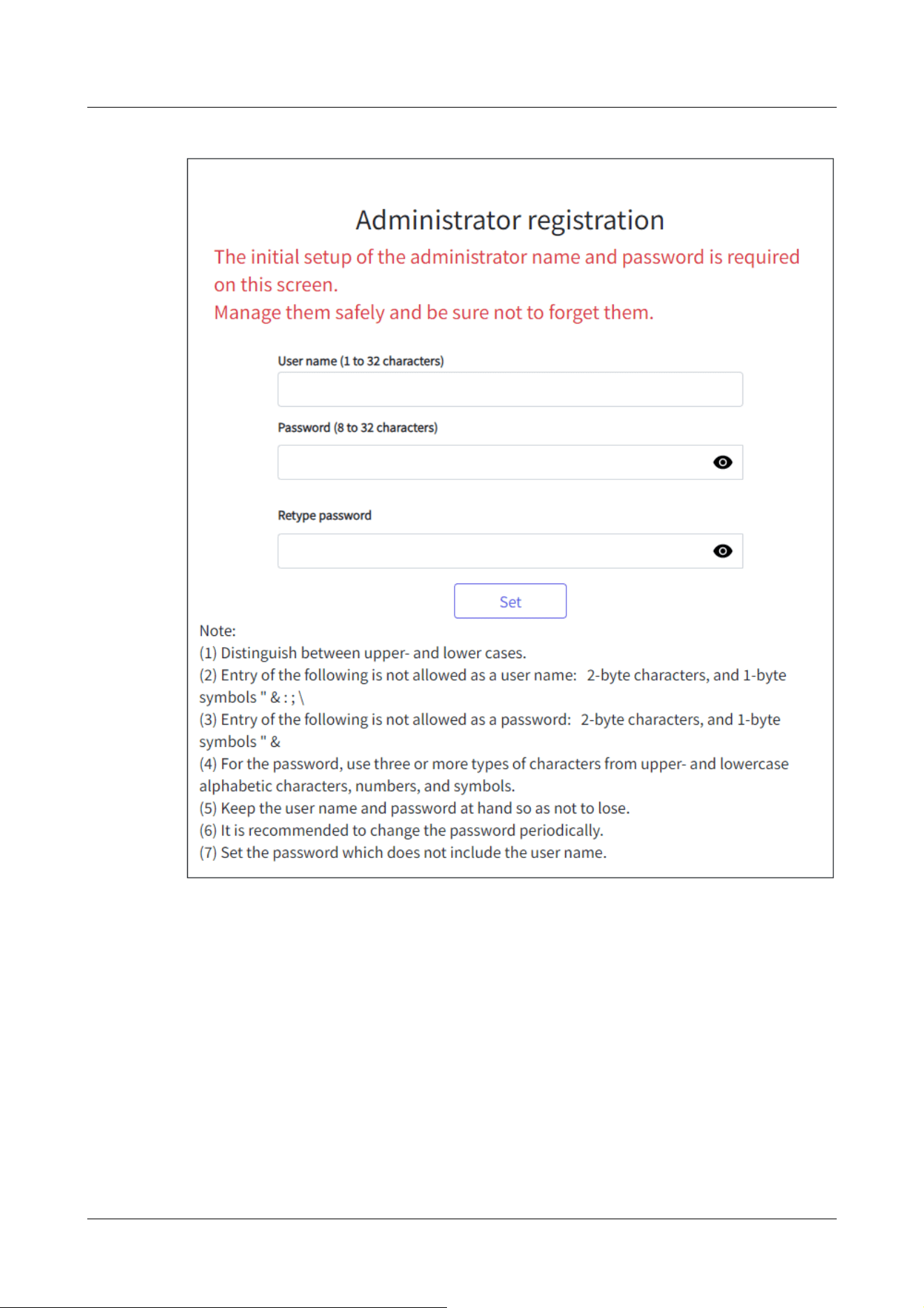
・
[User name (1 to 32 characters)]
Enter an administrator username.
・Number of characters that can be entered:1 to 32 characters
・Characters that cannot be entered:Double-byte and single-byte symbols&: ; ¥
・
[Password (8 to 32 characters)]/[Retype password]
Enter the administrator's password.
・Number of characters that can be entered:8 to 32 characters
・Characters that cannot be entered:Double-byte and single-byte symbols&
2 Operation
2.1 Initial Setting
19

[Note:]
・Enter case-sensitive data.
・Use at least three of the following passwords: uppercase alphabetic characters,
lowercase alphabetic characters, numbers, and symbols.
・Configure the password so that it does not contain the user name.
[Important]
・If the set user name or password is lost, the camera must be initialized. When the
camera is formatted, all settings will be cleared. Keep the user name and password
out of the eyes of third parties. Refer to the Web Guide for the formatting
method.
・Do not use other cameras, devices, or other passwords.
After registering the user name and password of the administrator, the Language/Datetime
setting screen is displayed.
Language/Datetime Settings
2 Operation
2.1 Initial Setting
20

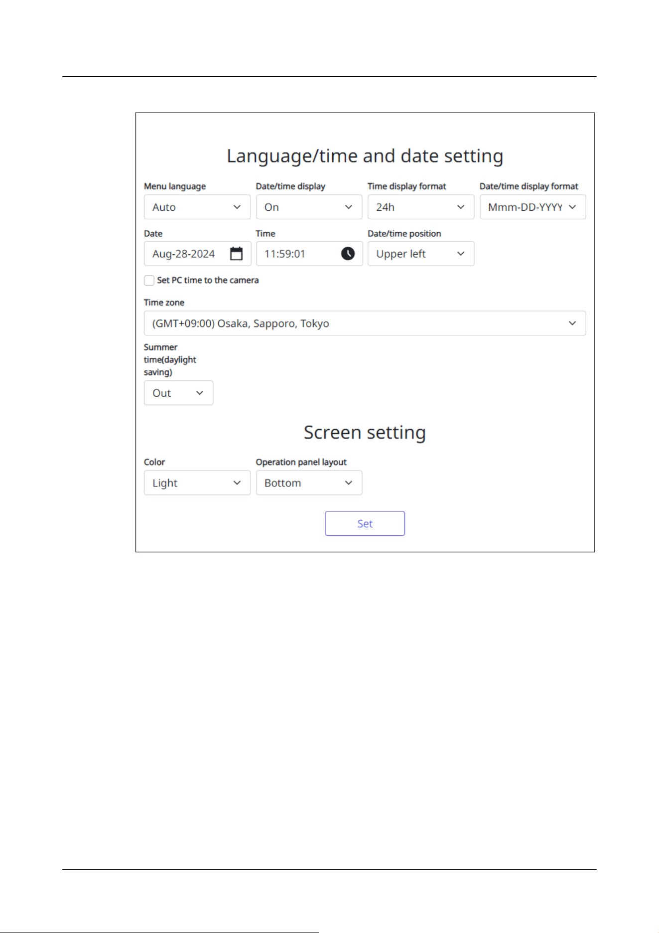
Language/Datetime Settings
・
[Menu language]
Select the first language that appears when you access the camera from the list below.
[Auto]/[English]/[Japanese]/[Italian]/[French]/[German]/[Spanish]/[Chinese]/[Russian]/
[Portuguese]
[Auto] automatically selects the languages used by the browser. If your computer is not
compatible with the language, the English language is selected.
・
[Time display format]
Select the time display method from 24h/12h.
・
[Date/time display format]
Select the date display format. If [Date/time] is set to [13:10:00 on April 1, 2021], the display
formats are as follows.
・DD/MM/YYYY: 01/04/2021 13:10:00
2 Operation
2.1 Initial Setting
21

[Important]
・If you need to set the time more accurately in system operation, use the NTP
server.
→16.2.3 Set up an NTP server
[Note:]
・If you want to set whether or not to display the date and time on the images, use
the [Basic] pages in the Advanced menu.
→9 [Basic] for basic setup of the machine
・MM/DD/YYYY: 04/01/2021 13:10:00
・DD/Mmm/YYYY: 01/Apr/2021 13:10:00
・YYYY/MM/DD: 2021/04/01 13:10:00
・Mmm/DD/YYYY: Apr/01/2021 13:10:00
・
[Date]
Click the button to set the camera date.
Click to get the date of the PC and display it.
・
[Time]
Click the button to enter the camera time.
Click to acquire the time of the PC and display it.
・
[Date/time position]
Select the position where the date and time are displayed on the image.
• [Upper left]: Displayed in the upper left corner of the window.
• [Lower left]: Displays in the lower left corner of the window.
• [Upper center]: Displayed in the center of the window.
• [Lower center]: Displays at the bottom center of the window.
• [Upper right]: Displayed in the upper right corner of the window.
• [Lower right]: Displays in the lower right corner of the window.
・
[Time zone]
Select the time zone for the camera area.
・
[Summer time(daylight saving)]
Use [In], [Out] and [Auto] to specify whether to use Daylight Saving Time. Set in the region
where Daylight Saving Time is used.
• [In] sets the time to Daylight Saving Time. [*] is displayed in the time display.
• [Out] cancels Daylight Saving Time.
• [Auto] switches to Daylight Saving Time according to the start date and time and end date
2 Operation
2.1 Initial Setting
22

settings (month, week, day of the week, and time).
・
[Start time & date] [End time & date]
When [Auto] is selected in [Summer time(daylight saving)] Setting, the start date and time of
Daylight Saving Time and the end date and time of Daylight Saving Time are set in Month,
Week, Day of Week, and Time.
Screen settings
・
[Character color]
Select the background color of the operation panels and advanced menus from the [Light]
[Dark].
・
[Operation panel layout]
Select the position of the control panel from [Right], [Left], and [Lower].
2.2 Initial setting (Multi-directional/PTZ integrated camera)
Administrator registration
The administrator registration screen is displayed when the camera is first accessed (or when the
camera is initialized).
Enter an administrator's user name and password to ensure that there are no mistakes. Use the
following login.
2 Operation
2.2 Initial setting (Multi-directional/PTZ integrated camera)
23
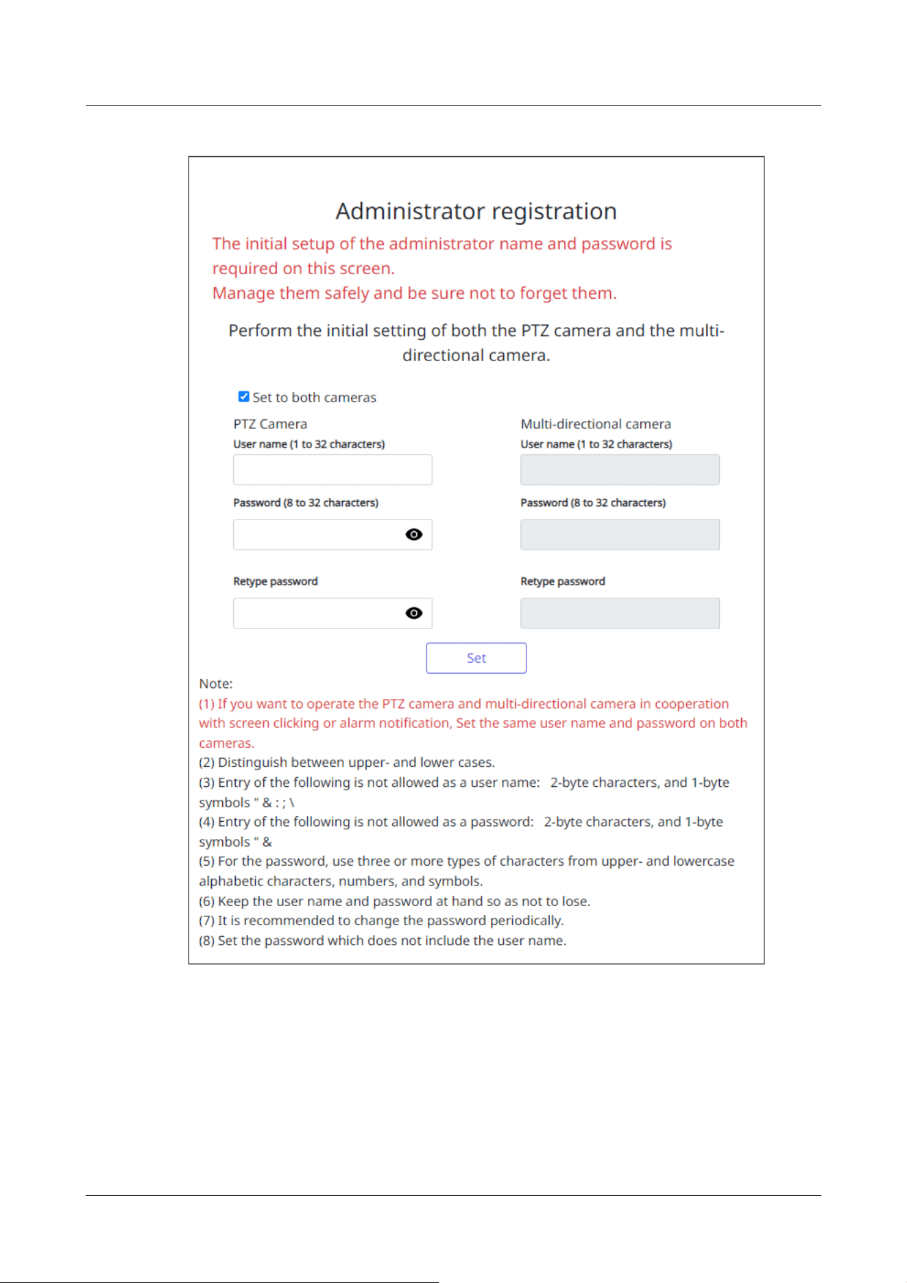
・
[Set to both cameras]
When the setting is performed with the checkbox checked, the [User name] and [Password]
entered into the PTZ camera are also set for the Multi-directional camera.
If you want to set up different administrator information for the PTZ camera and the
Multi-directional camera, uncheck the checkbox and enter [User name] and [Password].
・
[User name (1 to 32 characters)]
2 Operation
2.2 Initial setting (Multi-directional/PTZ integrated camera)
24

[Note:]
・Enter case-sensitive data.
・Use at least three of the following passwords: uppercase alphabetic characters,
lowercase alphabetic characters, numbers, and symbols.
・Configure the password so that it does not contain the user name.
・If you want the PTZ camera and the Multi-directional camera to work together by
screen clicking or alarm notification, set the same user name and password for
both cameras.
[Important]
・If the set user name or password is lost, the camera must be initialized. When the
camera is formatted, all settings will be cleared. Keep the user name and password
out of the eyes of third parties. Refer to the Operation Manual Web Guide for the
formatting method.
・Do not use other cameras, devices, or other passwords.
Enter an administrator username.
・Number of characters that can be entered:1 to 32 characters
・Characters that cannot be entered:Double-byte and single-byte symbols " & : ; ¥
・
[Password (8 to 32 characters)]/[Retype password]
Enter the administrator's password.
・Number of characters that can be entered:8 to 32 characters
・Characters that cannot be entered:Double-byte and single-byte symbols " &
After registering the user name and password of the administrator, the Language/Datetime
setting screen is displayed.
Language/Datetime Settings
2 Operation
2.2 Initial setting (Multi-directional/PTZ integrated camera)
25
Language/Datetime Settings
・
[Menu language]
Select the first language that appears when you access the camera from the list below.
[Auto]/[English]/[Japanese]/[Italian]/[French]/[German]/[Spanish]/[Chinese]/[Russian]/
[Portuguese]
[Auto] automatically selects the languages used by the browser. If your computer is not
compatible with the language, the English language is selected.
・
[Time display format]
Select the time display method from 24h/12h.
・
[Date/time display format]
Select the date display format. If [Date/time] is set to [13:10:00 on April 1, 2021], the display
formats are as follows.
・DD/MM/YYYY: 01/04/2021 13:10:00
2 Operation
2.2 Initial setting (Multi-directional/PTZ integrated camera)
26

[Important]
・If you need to set the time more accurately in system operation, use the NTP
server.
→16.2.3 Set up an NTP server
[Note:]
・If you want to set whether or not to display the date and time on the images, use
the [Basic] pages in the Advanced menu.
→9 [Basic] for basic setup of the machine
・MM/DD/YYYY: 04/01/2021 13:10:00
・DD/Mmm/YYYY: 01/Apr/2021 13:10:00
・YYYY/MM/DD: 2021/04/01 13:10:00
・Mmm/DD/YYYY: Apr/01/2021 13:10:00
・
[Date]
Click the button to set the camera date.
Click to get the date of the PC and display it.
・
[Time]
Click the button to enter the camera time.
Click to acquire the time of the PC and display it.
・
[Date/time position]
Select the position where the date and time are displayed on the image.
• [Upper left]: Displayed in the upper left corner of the window.
• [Lower left]: Displays in the lower left corner of the window.
• [Upper center]: Displayed in the center of the window.
• [Lower center]: Displays at the bottom center of the window.
• [Upper right]: Displayed in the upper right corner of the window.
• [Lower right]: Displays in the lower right corner of the window.
・
[Time zone]
Select the time zone for the camera area.
・
[Summer time(daylight saving)]
Use [In], [Out] and [Auto] to specify whether to use Daylight Saving Time. Set in the region
where Daylight Saving Time is used.
• [In] sets the time to Daylight Saving Time. [*] is displayed in the time display.
• [Out] cancels Daylight Saving Time.
• [Auto] switches to Daylight Saving Time according to the start date and time and end date
2 Operation
2.2 Initial setting (Multi-directional/PTZ integrated camera)
27
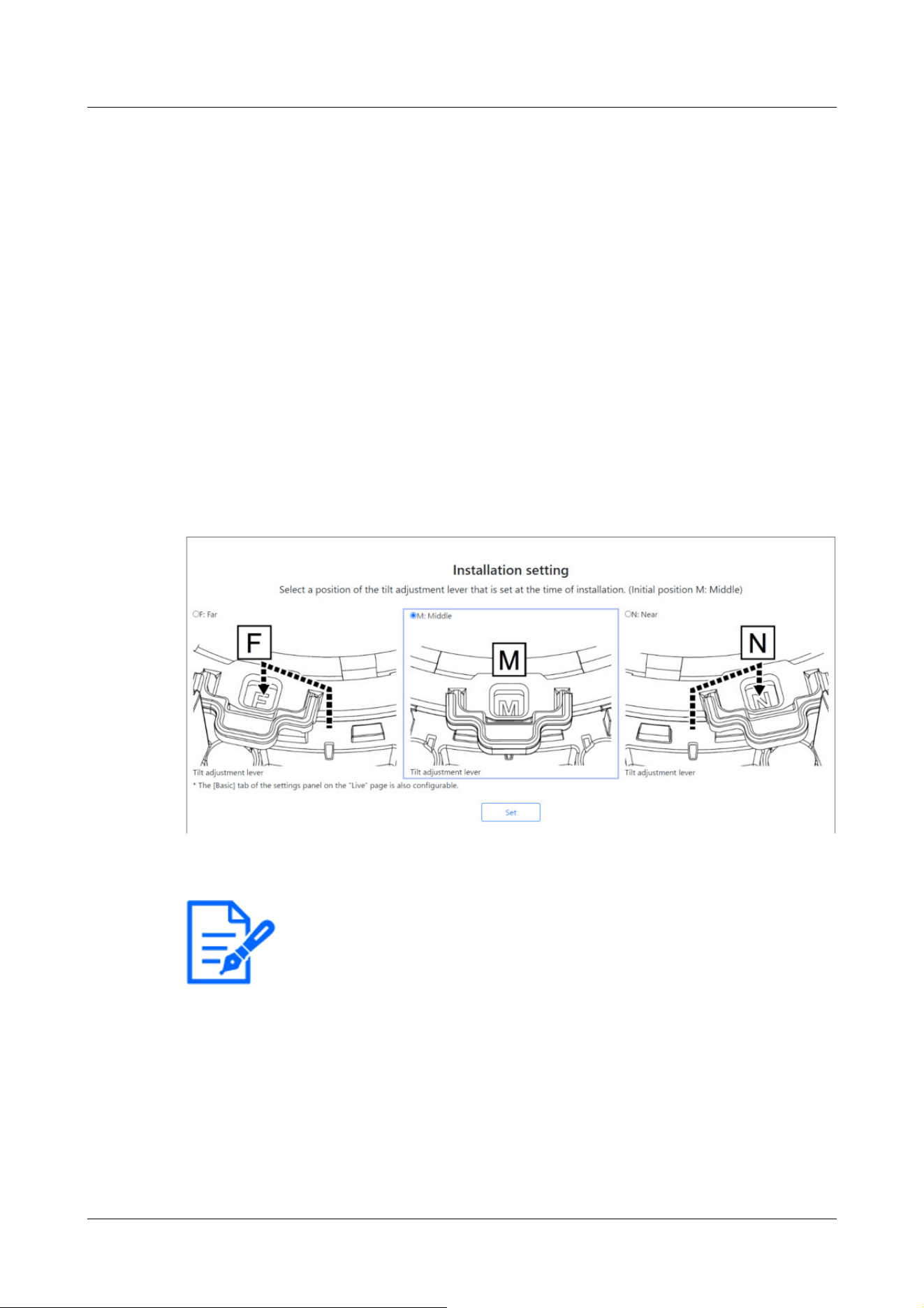
[Note:]
・[Tilt adjustment lever position] can also be set from the [Basic] tabs of the Live
Picture Settings pane. Please refer to the following for details.
→3.2 [Basic] to perform basic settings
settings (month, week, day of the week, and time).
・
[Start time & date] [End time & date]
When [Auto] is selected in [Summer time(daylight saving)] Setting, the start date and time of
Daylight Saving Time and the end date and time of Daylight Saving Time are set in Month,
Week, Day of Week, and Time.
Screen settings
・
[Character color]
Select the background color of the operation panels and advanced menus from the [Light]
[Dark].
・
[Operation panel layout]
Select the position of the control panel from [Right], [Left], and [Lower].
Set position
Select the [Tilt adjustment lever position] set when the cameras are installed.
2.3 Viewing images from a PC
This section explains how to view camera images from a PC.
2 Operation
2.3 Viewing images from a PC
28
[Important]
・If the HTTP port number is changed from [80], enter [http://Camera IP
address:Port number] in the [Address] box.
e.g., if the port number is set to 8080: http://192.168.0.11:8080
・If your computer is in a local network, configure the proxy server ([Set]-[Network
and Internet]-[Proxy]) to avoid using the proxy server for the local address.
・When IPv6 is accessed, the stream image cannot be displayed on the live screen.
If you want to display the stream image on the live screen, please access it via
IPv4.
[Note:]
・Due to browser limitations, there is an upper limit on the number of browsers that
can display video simultaneously. If you try to display images in multiple browsers,
the images may not be displayed.
・[HTTPS] on the [Advanced] tab of the network page-for the [HTTPS]
configuration in [Connection], the animated support video pages of please refer to
our technical information website<Control No. P0002><Control No. P0003>.
→16 Networking configuration [Network]
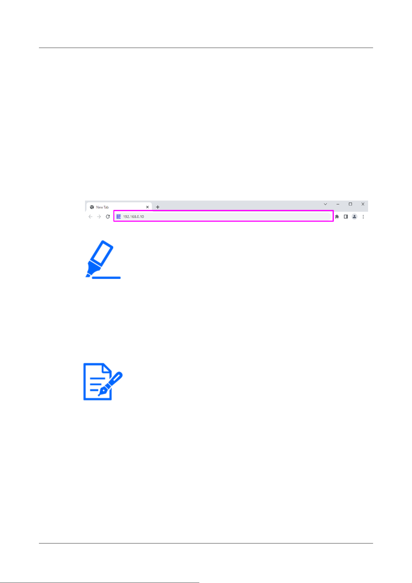
2.3.1 View camera images
1 Start the PC web browser.
2 Enter the IP addresses set in the IP Easy Configuration software in the [Address] boxes of
the web browser.
Example IPv4 address input:URL registered with the http://IPv4 address
http://192.168.0.10/
Example IPv6 address input:Http://[URL registered with IPv6 address]
Http://[2001:db8::10]/
<Example of IPv4 access>
3 Press the [Enter] key to display the user name and password entry screen.
2 Operation
2.3 Viewing images from a PC
29
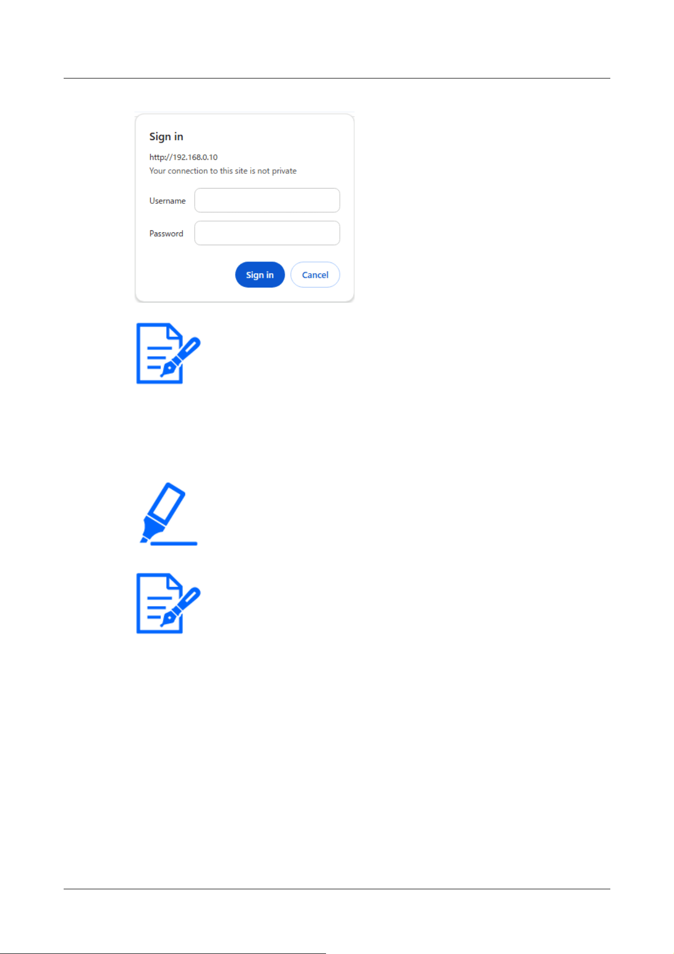
[Note:]
・If [User auth.] is set to [Off], the Username and Password entry window will not
be displayed prior to the live page.
[Important]
・If you try to display multiple H.265 (or H.264) images on a single PC, depending
on the performance of the PC, the image may not be displayed.
[Note:]
・Users with simultaneous access to this product are up to the sum of users
receiving H.265 (or H.264) images and users receiving JPEG images. However,
depending on the [Bandwidth control(bit rate)] [Bit Rate* per Client] setting, the
number of users that can be accessed may be limited to [Maximum number of
users] or less. If the number of accessible users exceeds [Maximum number of
users], an access excess message is displayed. When [Stream] [Transmission
type] is set to [Multicast], the second and subsequent users receiving H.265 (or
H.264) images are not counted as accesses.
・[Maximum number of users] depends on the model.
Up to 14 persons: PTZ camera, Multi-directional camera (2-eye U-series), Fixed
cameras
Up to 24 persons: Multi-directional camera (4 eyes), Multi-directional camera (3
4 Enter the username and password and click [OK] to display the Live image pages. For more
information on Live image pages, please see the following.
→2.3.2 About live image pages
2 Operation
2.3 Viewing images from a PC
30

eyes), Multi-directional camera (2 eyes/S-series)
・When [Stream transmission] is set to [On], the H.265 (or H.264) images are
displayed according to the [Stream encoding format] settings. When set to [Off],
JPEG images are displayed. JPEG images can be displayed even if [Stream
transmission] is set to [On]. However, in this case, the image update rate of the
JPEG image is limited as shown in the table below.
→10.3 [Image] for setting up streams
・Image updating speed of JPEG images may be slow depending on network
environments, PC performance, object, and number of accesses.
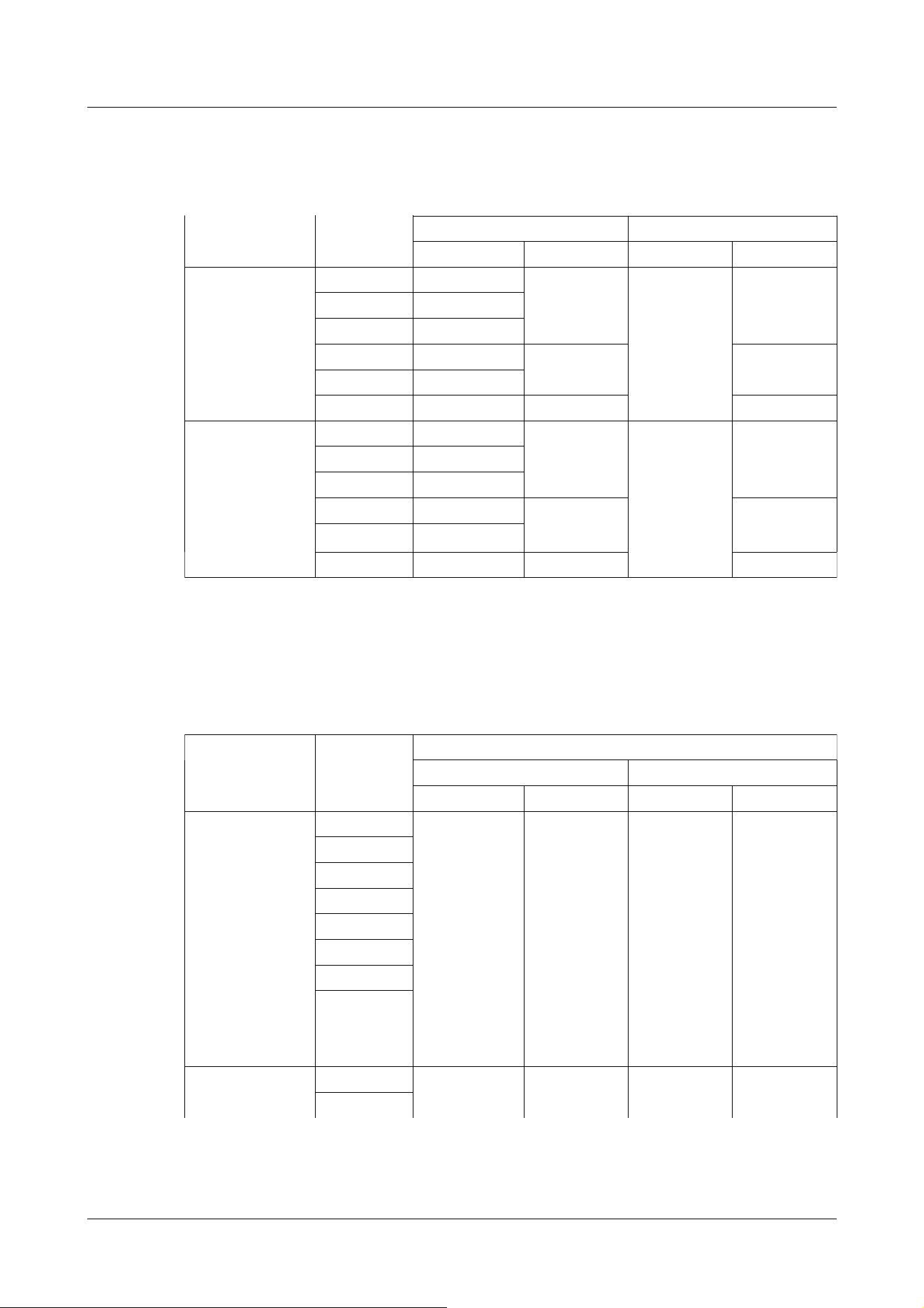
Rapid PTZ cameras (X/S series, Image capture size: 8M (4K)), Indoor PTZ cameras (Image
capture size: 8M (4K)), Aero PTZ cameras (Image capture size: 8M (4K))
Image capture
mode
Image
capture size
Stream delivery
On Off
JPEG(1) JPEG(2) JPEG(1) JPEG(2)
16:9 mode(30fps
mode)
3840x2160 Up to 1 fps - Up to 30 fps -
2560x1440 Up to 2 fps
1920x1080 Up to 5 fps
1280x720 Up to 5 fps Up to 15 fps
*1
Up to 30 fps
*1
640x360 Up to 5 fps
320x180 Up to 5 fps - -
16:9 mode(25fps
mode)
3840x2160 Up to 1 fps - Up to 25 fps -
2560x1440 Up to 2.1 fps
1920x1080 Up to 4.2 fps
1280x720 Up to 4.2 fps Up to 12.5
fps
*1
Up to 25 fps
*1
640x360 Up to 4.2 fps
320x180 Up to 4.2 fps - -
Rapid PTZ cameras (X/S series, Image capture size: 6MP), Indoor PTZ cameras (Image capture
size: 6MP)
Image capture Image Stream delivery
PTZ camera
Please refer to the following for the relationship between your model and symbols and terminology.
→1.2 Compatible models and symbols in this manual
*1 JPEG (2) is set to [1280x720] if [640x360] is not selected for the resolution set in Streams (1),
Streams (2), Streams (3), Streams (4), and JPEG (1) and four resolutions are set.
2 Operation
2.3 Viewing images from a PC
31
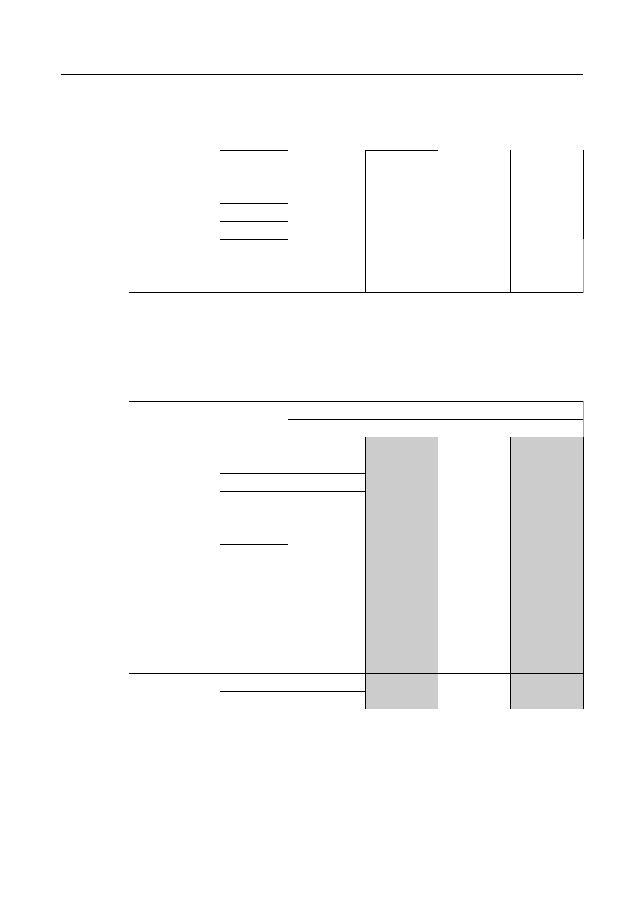
Rapid PTZ cameras (X/S series, Image capture size: 6MP), Indoor PTZ cameras (Image capture
size: 6MP)
(continued)
mode capture size
On Off
JPEG(1) JPEG(2) JPEG(1) JPEG(2)
16:9 mode(30fps
mode)
3328x1872 Up to 1 fps - Up to 30 fps -
2560x1440 Up to 2 fps
1920x1080 Up to 5 fps
1280x720 Up to 5 fps Up to 15 fps
*1
Up to 30 fps
*1
640x360 Up to 5 fps
320x180 Up to 5 fps - -
16:9 mode(25fps
mode)
3328x1872 Up to 1 fps - Up to 25 fps -
2560x1440 Up to 2.1 fps
1920x1080 Up to 4.2 fps
1280x720 Up to 4.2 fps Up to 12.5
fps
*1
Up to 25 fps
*1
640x360 Up to 4.2 fps
320x180 Up to 4.2 fps - -
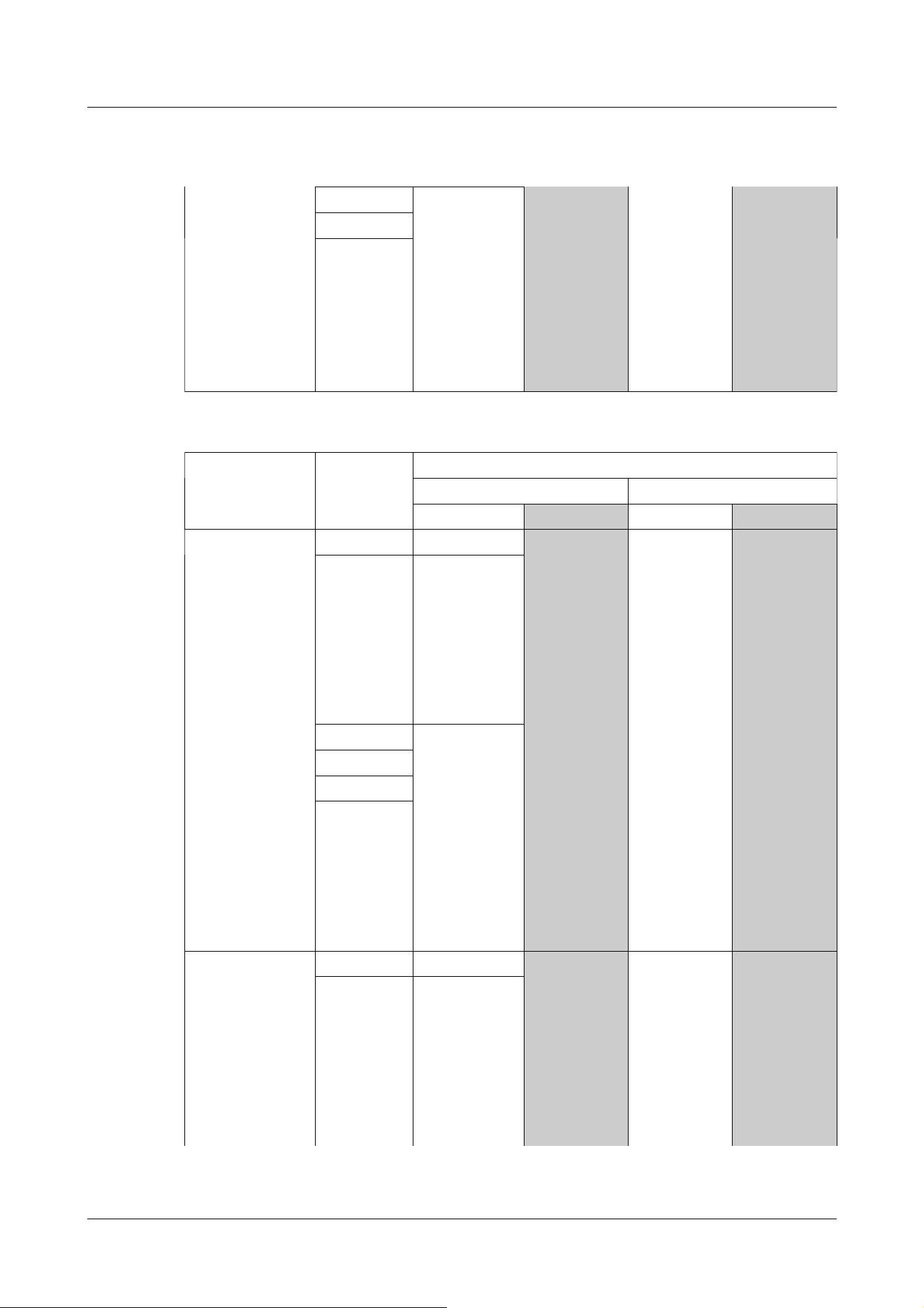
Rapid PTZ camera (X/S series, Image capture size: 2MP), Multi-directional + PTZ (PTZ part),
Aero PTZ cameras (Image capture size: 2MP)
Image capture
mode
Image
capture size
Stream delivery
On Off
JPEG(1) JPEG(2) JPEG(1) JPEG(2)
16:9 mode(30fps
mode)
16:9 mode(60fps
mode)
4:3 mode(15fps
mode)
4:3 mode(30fps
mode)
1920x1080 Up to 5 fps Up to 15 fps Up to 30 fps
(*)
(*) Up to 15
fps if Image
capture mode
is 15 fps
Up to 30 fps
(*)
(*) Up to 15
fps if Image
capture mode
is 15 fps
1280x720
640x360
320x180
2048x1536
1280x960
VGA
QVGA
16:9 mode(25fps
mode)
1920x1080 Up to 4.2 fps Up to 12.5 fps
Up to 25 fps(*) Up to 25 fps(*)
1280x720
*1 JPEG (2) is set to [1280x720] if [640x360] is not selected for the resolution set in Streams (1),
Streams (2), Streams (3), Streams (4), and JPEG (1) and four resolutions are set.
2 Operation
2.3 Viewing images from a PC
32
Rapid PTZ camera (X/S series, Image capture size: 2MP), Multi-directional + PTZ (PTZ part),
Aero PTZ cameras (Image capture size: 2MP)
(continued)
16:9 mode(50fps
mode)
4:3 mode(12.5fps
mode)
4:3 mode(25fps
mode)
(*) Up to 12.5
fps when
Image capture
mode is 12.5
fps
(*) Up to 12.5
fps when
Image capture
mode is 12.5
fps
640x360
320x180
2048x1536
1280x960
VGA
QVGA
Multi-directional cameras (8-megapixel models)
Imaging mode Resolution Stream delivery
On Off
JPEG(1) JPEG(2) JPEG(1) JPEG(2)
8 megapixels
[16:9](15 fps
mode)
8 megapixels
[16:9](12.5 fps
mode)
3840x2160 Up to 1 fps -(no function)
Up to 15 fps(*)
Up to 12.5 fps
for the (*)
imaging mode
of 12.5 fps
-(no function)
2560x1440 Up to 2 fps
1920x1080 Up to 5 fps
1280x720
640x360
320x180
8 megapixels
[16:9](15 fps Dual
3840x2160 Up to 1 fps -(no function)
Up to 15 fps(*)
-(no function)
2560x1440 Up to 2.1 fps
Multi-directional camera
Please refer to the following for the relationship between your model and symbols and terminology.
→1.2 Compatible models and symbols in this manual
2 Operation
2.3 Viewing images from a PC
33
Multi-directional cameras (8-megapixel models)
(continued)
mode)
8 megapixels
[16:9](12.5 fps
Dual mode) Up to 12.5 fps
for the (*)
imaging mode
of 12.5 fps
1920x1080 Up to 4.2 fps
1280x720
640x360
Multi-directional camera (5-megapixel model)
Imaging mode Resolution Stream delivery
On Off
JPEG(1) JPEG(2) JPEG(1) JPEG(2)
5 megapixels
[16:9](15fps mode)
5 megapixels
[16:9](12.5fps
mode)
3072x1728 Up to 1 fps -(no function)
Up to 15 fps(*)
Up to 12.5 fps
for the (*)
imaging mode
of 12.5 fps
-(no function)
2560x1440 Up to 2 fps(*)
Up to 12.5 fps
for the (*)
imaging mode
of 2.1 fps
1920x1080 Up to 5 fps(*)
Up to 12.5 fps
for the (*)
imaging mode
of 4.2 fps
1280x720
640x360
320x180
5 megapixels
[16:9](15fps Quad
mode)
5 megapixels
[16:9](12.5fps
Quad mode)
3072x1728 Up to 1 fps -(no function)
Up to 15 fps(*)
-(no function)
2560x1440 Up to 2 fps(*)
Up to 12.5 fps
for the (*)
imaging mode
of 2.1 fps
2 Operation
2.3 Viewing images from a PC
34

Multi-directional camera (5-megapixel model)
(continued)
Up to 12.5 fps
for the (*)
imaging mode
of 12.5 fps
1920x1080 Up to 5 fps(*)
Up to 12.5 fps
for the (*)
imaging mode
of 4.2 fps
1280x720
640x360
5 megapixels
[4:3](15fps mode)
5 megapixels
[4:3](12.5fps
mode)
3072x2304 Up to 1 fps -(no function)
Up to 15 fps(*)
Up to 12.5 fps
for the (*)
imaging mode
of 12.5 fps
-(no function)
2560x1920 Up to 2 fps(*)
Up to 12.5 fps
for the (*)
imaging mode
of 2.1 fps
1280x960 Up to 5 fps(*)
Up to 12.5 fps
for the (*)
imaging mode
of 4.2 fps
640x480
320x240
5 megapixels
[4:3](15fps Quad
mode)
5 megapixels
[4:3](12.5fps
Quad mode)
3072x2304 Up to 1 fps -(no function)
Up to 15 fps(*)
Up to 12.5 fps
for the (*)
imaging mode
of 12.5 fps
-(no function)
2560x1920 Up to 2 fps(*)
Up to 12.5 fps
for the (*)
imaging mode
of 2.1 fps
1280x960 Up to 5 fps(*)
Up to 12.5 fps
for the (*)
imaging mode
of 4.2 fps
640x480
Multi-directional camera (4-megapixel model)
Imaging mode Resolution Stream delivery
2 Operation
2.3 Viewing images from a PC
35

Multi-directional camera (4-megapixel model)
(continued)
On Off
JPEG(1) JPEG(2) JPEG(1) JPEG(2)
4 mega pixel
[16:9](30fps mode)
4 mega pixel
[16:9](25fps mode)
2688x1520 Up to 2 fps(*)
Up to 25 fps for
the (*) imaging
mode of 2.1 fps
-(no function)
Up to 30 fps(*)
Up to 25 fps
for the (*)
imaging mode
of 25 fps
-(no function)
2560x1440
1920x1080 Up to 5 fps(*)
Up to 25 fps for
the (*) imaging
mode of 4.2 fps
1280x720
640x360
320x180
4 mega pixel
[16:9](30fps Dual
mode)
4 mega pixel
[16:9](25fps Dual
mode)
2688x1520 Up to 2 fps(*)
Up to 25 fps for
the (*) imaging
mode of 2.1 fps
-(no function)
Up to 30 fps(*)
Up to 25 fps
for the (*)
imaging mode
of 25 fps
-(no function)
2560x1440
1920x1080 Up to 5 fps(*)
Up to 25 fps for
the (*) imaging
mode of 4.2 fps
1280x720
640x360
Compact Dome cameras (X/S series, Image capture size: 4MP)
Image capture
mode
Image capture
size
Stream delivery
On Off
JPEG(1) JPEG(2) JPEG(1) JPEG(2)
16:9 mode
(2688x1520 30fps
mode)
2688x1520 Up to 2
fps/2.1 fps
*1
- Up to 30
fps/25 fps
Up to 30
fps/25 fps
1920x1080 Up to 5
Compact Dome cameras
Please refer to the following for the relationship between your model and symbols and terminology.
→1.2 Compatible models and symbols in this manual
2 Operation
2.3 Viewing images from a PC
36

Compact Dome cameras (X/S series, Image capture size: 4MP)
(continued)
16:9 mode
(2688x1520 25fps
mode)
fps/4.2 fps
*1
1280x720
640x360 Up to 15
fps/12.5 fps
320x180 -
16:9 mode(30fps
mode)
16:9 mode(25fps
mode)
2560x1440 Up to 2
fps/2.1 fps
*1
- Up to 30
fps/25 fps
Up to 30
fps/25 fps
1920x1080 Up to 5
fps/4.2 fps
*1
1280x720
640x360 Up to 15
fps/12.5 fps
320x180 -
4:3 mode(30fps
mode)
4:3 mode(25fps
mode)
1280x960 Up to 5
fps/4.2 fps
- Up to 30
fps/25 fps
Up to 30
fps/25 fps
640x480 Up to 15
fps/12.5 fps
320x240 -
4:3 mode(15fps
mode)
4:3 mode(12.5fps
mode)
2048x1536 Up to 5
fps/4.2 fps
- Up to 15
fps/12.5 fps
Up to 15
fps/12.5 fps
1280x960
640x480 Up to 15
fps/12.5 fps
320x240 -
Compact Dome cameras (X/S series, Image capture size: 2MP)
Image capture
mode
Image capture
size
Stream delivery
On Off
JPEG(1) JPEG(2) JPEG(1) JPEG(2)
16:9 mode(60fps
mode)
16:9 mode(50fps
mode)
1920x1080 Up to 5
fps/4.2 fps
*1
- Up to 30
fps/25 fps
Up to 30
fps/25 fps
1280x720
640x360 Up to 15
fps/12.5 fps
320x180 -
16:9 mode(30fps
mode)
16:9 mode(25fps
1920x1080 Up to 5
fps/4.2 fps
*1
- Up to 30
fps/25 fps
Up to 30
fps/25 fps
1280x720
*1 Only the same Image capture size as that set in streams (1), streams (2), streams (3), and
JPEG (2) can be selected.
2 Operation
2.3 Viewing images from a PC
37

Compact Dome cameras (X/S series, Image capture size: 2MP)
(continued)
mode)
640x360 Up to 15
fps/12.5 fps
320x180 -
4:3 mode(30fps
mode)
4:3 mode(25fps
mode)
1280x960 Up to 5
fps/4.2 fps
- Up to 30
fps/25 fps
Up to 30
fps/25 fps
640x480 Up to 15
fps/12.5 fps
320x240 -
4:3 mode(15fps
mode)
4:3 mode(12.5fps
mode)
2048x1536 Up to 5
fps/4.2 fps
- Up to 15
fps/12.5 fps
Up to 15
fps/12.5 fps
1280x960
640x480 Up to 15
fps/12.5 fps
320x240 -
Compact Dome cameras (U series, Image capture size: 4MP)
Image capture
mode
Image capture
size
Stream delivery
On Off
JPEG(1) JPEG(2) JPEG(1) JPEG(2)
16:9 mode
(2688x1520 30fps
mode)
16:9 mode
(2688x1520 25fps
mode)
2688x1520 Up to 3
fps/3.1 fps
- Up to 10
fps/8.3 fps
-
1920x1080
1280x720
640x360
16:9 mode(30fps
mode)
16:9 mode(25fps
mode)
2560x1440 Up to 3
fps/3.1 fps
*1
Up to 5
fps/4.2 fps
*1
Up to 10
fps/8.3 fps
Up to 30
fps/25 fps
1920x1080
1280x720
640x360
320x180
4:3 mode(30fps
mode)
4:3 mode(25fps
mode)
1280x960 Up to 3
fps/3.1 fps
Up to 5
fps/4.2 fps
Up to 10
fps/8.3 fps
Up to 30
fps/25 fps
640x480
320x240
4:3 mode(15fps
mode)
4:3 mode(12.5fps
mode)
2048x1536 Up to 3
fps/3.1 fps
Up to 5
fps/4.2 fps
Up to 10
fps/8.3 fps
Up to 15
fps/12.5 fps
1280x960
640x480
320x240
2 Operation
2.3 Viewing images from a PC
38

Compact Dome cameras (U series, Image capture size: 2MP)
Image capture
mode
Image capture
size
Stream delivery
On Off
JPEG(1) JPEG(2) JPEG(1) JPEG(2)
16:9 mode(30fps
mode)
16:9 mode(25fps
mode)
1920x1080 Up to 3
fps/3.1 fps
- Up to 10
fps/8.3 fps
Up to 30
fps/25 fps
1280x720
640x360 Up to 5
fps/4.2 fps
320x180 -
4:3 mode(30fps
mode)
4:3 mode(25fps
mode)
1280x960 Up to 5
fps/4.2 fps
- Up to 10
fps/8.3 fps
Up to 30
fps/25 fps
640x480 Up to 5
fps/4.2 fps
320x240 -
New X fixed camera (Image capture size: 2MP)
Image capture
mode
Image capture
size
Stream delivery
On Off
JPEG(1) JPEG(2) JPEG(1) JPEG(2)
16:9 mode(30fps
mode)
16:9 mode(25fps
mode)
1920x1080 Up to 5
fps/4.2 fps
- Up to 30
fps/25 fps
-
1280x720
640x360 Up to 15
fps/12.5 fps
Up to 30
fps/25 fps
320x180 - -
16:9 mode(60fps
mode)
16:9 mode(50fps
mode)
1920x1080 Up to 5
fps/4.2 fps
- Up to 30
fps/25 fps
-
1280x720
640x360 Up to 15
fps/12.5 fps
Up to 30
fps/25 fps
320x180 - -
*1 If the frame rate of stream (1) and stream (2) is set to 30fps, it will be limited to a
maximum of 1fps.
New X fixed camera
Please refer to the following for the relationship between your model and symbols and terminology.
→1.2 Compatible models and symbols in this manual
2 Operation
2.3 Viewing images from a PC
39

New X fixed camera (Image capture size: 2MP)
(continued)
4:3 mode(30fps
mode)
4:3 mode(25fps
mode)
2048x1536 Up to 5
fps/4.2 fps
- Up to 30
fps/25 fps
-
1280x960
640x480 Up to 15
fps/12.5 fps
Up to 30
fps/25 fps
320x240 - -
4:3 mode(60fps
mode)
4:3 mode(50fps
mode)
2048x1536 Up to 5
fps/4.2 fps
- Up to 15
fps/12.5 fps
-
1280x960
640x480 Up to 15
fps/12.5 fps
Up to 15
fps/12.5 fps
320x240 - -
New X fixed camera (Image capture size: 5MP)
Image capture
mode
Image capture
size
Stream delivery
On Off
JPEG(1) JPEG(2) JPEG(1) JPEG(2)
16:9 mode(30fps
mode)
16:9 mode(25fps
mode)
3072x1728 Up to 1 fps
*1
- Up to 30
fps/25 fps
-
2560x1440 Up to 2
fps/2.1 fps
*1
1920x1080 Up to 5
fps/4.2 fps
*1
1280x720 Up to 15 fps/
12.5 fps
*2
Up to 30 fps/
25 fps
640x360
320x180 - -
16:9 mode(60fps
mode)
16:9 mode(50fps
mode)
-(no function) -(no function) -(no function) -(no function) -(no function)
4:3 mode(30fps
mode)
4:3 mode(25fps
mode)
3072x2304 Up to 1 fps
*1
- Up to 30
fps/25 fps
-
2560x1920 Up to 2
fps/2.1 fps
*1
1280x960 Up to 5
fps/4.2 fps
*1
800x600
VGA Up to 15
fps/12.5 fps
Up to 30
fps/25 fps
400x300 - -
QVGA
2 Operation
2.3 Viewing images from a PC
40

New X fixed camera (Image capture size: 5MP)
(continued)
4:3 mode(60fps
mode)
4:3 mode(50fps
mode)
-(no function) -(no function) -(no function) -(no function) -(no function)
New X fixed camera (Image capture size: 6MP)
Image capture
mode
Image capture
size
Stream delivery
On Off
JPEG(1) JPEG(2) JPEG(1) JPEG(2)
16:9 mode(30fps
mode)
16:9 mode(25fps
mode)
3328x1872 Up to 1 fps
*1
- Up to 30
fps/25 fps
-
2560x1440 Up to 2
fps/2.1 fps
*1
1920x1080 Up to 5
fps/4.2 fps
*1
1280x720 Up to 15 fps/
12.5 fps
*2
Up to 30 fps/
25 fps
640x360
320x180 - -
16:9 mode(60fps
mode)
16:9 mode(50fps
mode)
-(no function) -(no function) -(no function) -(no function) -(no function)
New X fixed camera (Image capture size: 8MP)
Image capture
mode
Image capture
size
Stream delivery
On Off
*1 Only the same Image capture size as configured in stream (1), stream (2), stream (3),
stream (4), and JPEG (2) can be selected.
*2 JPEG (2) is set to [1280x720] if [640x360] is not selected for the resolution set in
Streams (1), Streams (2), Streams (3), Streams (4), and JPEG (1) and four resolutions are
set.
2 Operation
2.3 Viewing images from a PC
41

New X fixed camera (Image capture size: 8MP)
(continued)
JPEG(1) JPEG(2) JPEG(1) JPEG(2)
16:9 mode(30fps
mode)
16:9 mode(25fps
mode)
3840x2160 Up to 1 fps
*1
- Up to 30
fps/25 fps
-
2560x1440 Up to 2
fps/2.1 fps
*1
1920x1080 Up to 5
fps/4.2 fps
*1
1280x720 Up to 15 fps/
12.5 fps
*2
Up to 30 fps/
25 fps
640x360
320x180 - -
16:9 mode(60fps
mode)
16:9 mode(50fps
mode)
-(no function) -(no function) -(no function) -(no function) -(no function)
Corner cameras (Image capture size: 5MP)
Image capture
mode
Image capture
size
Stream delivery
On Off
JPEG(1) JPEG(2) JPEG(1) JPEG(2)
16:9 mode(30fps
mode)
16:9 mode(25fps
mode)
3072x1728 Up to 1 fps
*1
- Up to 30
fps/25 fps
Up to 30
fps/25 fps
2560x1440 Up to 2 fps
*1
1920x1080 Up to 5
fps/4.2 fps
*1
1280x720 Up to 15 fps/
12.5 fps
*2
640x360
320x180 -
4:3 mode(30fps
mode)
3072x2304 Up to 1 fps
*1
- Up to 30
fps/25 fps
Up to 30
fps/25 fps
2560x1920 Up to 2 fps
*1
*1 Only the same Image capture size as configured in stream (1), stream (2), stream (3),
stream (4), and JPEG (2) can be selected.
*2 JPEG (2) is set to [1280x720] if [640x360] is not selected for the resolution set in
Streams (1), Streams (2), Streams (3), Streams (4), and JPEG (1) and four resolutions are
set.
Corner cameras
Please refer to the following for the relationship between your model and symbols and terminology.
→1.2 Compatible models and symbols in this manual
2 Operation
2.3 Viewing images from a PC
42

Corner cameras (Image capture size: 5MP)
(continued)
4:3 mode(25fps
mode)
1280x960 Up to 5
fps/4.2 fps
*1
800x600
VGA Up to 15
fps/12.5 fps
400x300 -
QVGA
AI Outdoor IR Bullet Camera (X series, Image capture size: 8MP)
Image capture
mode
Image capture
size
Stream delivery
On Off
JPEG(1) JPEG(2) JPEG(1) JPEG(2)
16:9 mode(30fps
mode)
16:9 mode(25fps
mode)
3840x2160 Up to 1 fps
*1
- Up to 30
fps/25 fps
-
2560x1440 Up to 2
fps/2.1 fps
*1
1920x1080 Up to 5
fps/4.2 fps
*1
1280x720 Up to 15 fps/
12.5 fps
*2
Up to 30 fps/
25 fps
640x360
320x180 - -
16:9 mode(60fps
mode)
16:9 mode(50fps
mode)
-(no function) -(no function) -(no function) -(no function) -(no function)
*1 Only the same Image capture size as configured in stream (1), stream (2), stream (3),
stream (4), and JPEG (2) can be selected.
*2 JPEG (2) is set to [1280x720] if [640x360] is not selected for the resolution set in
Streams (1), Streams (2), Streams (3), Streams (4), and JPEG (1) and four resolutions are
set.
AI Outdoor IR Bullet Camera
*1 Only the same Image capture size as configured in stream (1), stream (2), stream (3),
stream (4), and JPEG (2) can be selected.
*2 JPEG (2) is set to [1280x720] if [640x360] is not selected for the resolution set in
Streams (1), Streams (2), Streams (3), Streams (4), and JPEG (1) and four resolutions are
set.
2 Operation
2.3 Viewing images from a PC
43

AI Outdoor IR Bullet Camera (X series, Image capture size: 5MP)
Image capture
mode
Image capture
size
Stream delivery
On Off
JPEG(1) JPEG(2) JPEG(1) JPEG(2)
16:9 mode(30fps
mode)
16:9 mode(25fps
mode)
3072x1728 Up to 1 fps
*1
- Up to 30
fps/25 fps
-
2560x1440 Up to 2
fps/2.1 fps
*1
1920x1080 Up to 5
fps/4.2 fps
*1
1280x720 Up to 15 fps/
12.5 fps
*2
Up to 30 fps/
25 fps
640x360
320x180 - -
16:9 mode(60fps
mode)
16:9 mode(50fps
mode)
-(no function) -(no function) -(no function) -(no function) -(no function)
4:3 mode(30fps
mode)
4:3 mode(25fps
mode)
3072x2304 Up to 1 fps
*1
- Up to 30
fps/25 fps
-
2560x1920 Up to 2
fps/2.1 fps
*1
1280x960 Up to 5
fps/4.2 fps
*1
800x600
VGA Up to 15
fps/12.5 fps
Up to 30
fps/25 fps
400x300 - -
QVGA
4:3 mode(60fps
mode)
4:3 mode(50fps
mode)
-(no function) -(no function) -(no function) -(no function) -(no function)
AI Outdoor IR Bullet Camera (X series, Image capture size: 2MP)
Image capture
mode
Image capture
size
Stream delivery
On Off
*1 Only the same Image capture size as configured in stream (1), stream (2), stream (3),
stream (4), and JPEG (2) can be selected.
*2 JPEG (2) is set to [1280x720] if [640x360] is not selected for the resolution set in
Streams (1), Streams (2), Streams (3), Streams (4), and JPEG (1) and four resolutions are
set.
2 Operation
2.3 Viewing images from a PC
44

AI Outdoor IR Bullet Camera (X series, Image capture size: 2MP)
(continued)
JPEG(1) JPEG(2) JPEG(1) JPEG(2)
16:9 mode(30fps
mode)
16:9 mode(25fps
mode)
1920x1080 Up to 5
fps/4.2 fps
- Up to 30
fps/25 fps
-
1280x720
640x360 Up to 15
fps/12.5 fps
Up to 30
fps/25 fps
320x180 - -
16:9 mode(60fps
mode)
16:9 mode(50fps
mode)
1920x1080 Up to 5
fps/4.2 fps
- Up to 30
fps/25 fps
-
1280x720
640x360 Up to 15
fps/12.5 fps
Up to 30
fps/25 fps
320x180 - -
4:3 mode(30fps
mode)
4:3 mode(25fps
mode)
2048x1536 Up to 5
fps/4.2 fps
- Up to 30
fps/25 fps
-
1280x960
640x480 Up to 15
fps/12.5 fps
Up to 30
fps/25 fps
320x240 - -
4:3 mode(60fps
mode)
4:3 mode(50fps
mode)
2048x1536 Up to 5
fps/4.2 fps
- Up to 15
fps/12.5 fps
-
1280x960
640x480 Up to 15
fps/12.5 fps
Up to 15
fps/12.5 fps
320x240 - -
AI Outdoor IR Bullet Camera (S series, Image capture size: 8MP)
Image capture
mode
Image capture
size
Stream delivery
On Off
JPEG(1) JPEG(2) JPEG(1) JPEG(2)
16:9 mode(30fps
mode)
16:9 mode(25fps
mode)
3840x2160 Up to 1 fps
*1
- Up to 30
fps/25 fps
-
2560x1440 Up to 2
fps/2.1 fps
*1
1920x1080 Up to 5
fps/4.2 fps
*1
1280x720 Up to 15 fps/
12.5 fps
*2
Up to 30 fps/
25 fps
640x360
320x180 - -
2 Operation
2.3 Viewing images from a PC
45

AI Outdoor IR Bullet Camera (S series, Image capture size: 5MP)
Image capture
mode
Image capture
size
Stream delivery
On Off
JPEG(1) JPEG(2) JPEG(1) JPEG(2)
16:9 mode(30fps
mode)
16:9 mode(25fps
mode)
3072x1728 Up to 1 fps
*1
- Up to 30
fps/25 fps
-
2560x1440 Up to 2
fps/2.1 fps
*1
1920x1080 Up to 5
fps/4.2 fps
*1
1280x720 Up to 15 fps/
12.5 fps
*2
Up to 30 fps/
25 fps
640x360
320x180 - -
4:3 mode(30fps
mode)
4:3 mode(25fps
mode)
3072x2304 Up to 1 fps
*1
- Up to 30
fps/25 fps
-
2560x1920 Up to 2
fps/2.1 fps
*1
1280x960 Up to 5
fps/4.2 fps
*1
800x600
VGA Up to 15
fps/12.5 fps
Up to 30
fps/25 fps
400x300 - -
QVGA
AI Outdoor IR Bullet Camera (S series, Image capture size: 2MP)
Image capture
mode
Image capture
size
Stream delivery
On Off
JPEG(1) JPEG(2) JPEG(1) JPEG(2)
*1 Only the same Image capture size as configured in stream (1), stream (2), stream (3),
stream (4), and JPEG (2) can be selected.
*2 JPEG (2) is set to [1280x720] if [640x360] is not selected for the resolution set in
Streams (1), Streams (2), Streams (3), Streams (4), and JPEG (1) and four resolutions are
set.
2 Operation
2.3 Viewing images from a PC
46

AI Outdoor IR Bullet Camera (S series, Image capture size: 2MP)
(continued)
16:9 mode(30fps
mode)
16:9 mode(25fps
mode)
1920x1080 Up to 5
fps/4.2 fps
- Up to 30
fps/25 fps
-
1280x720
640x360 Up to 15
fps/12.5 fps
Up to 30
fps/25 fps
320x180 - -
16:9 mode(60fps
mode)
16:9 mode(50fps
mode)
1920x1080 Up to 5
fps/4.2 fps
- Up to 30
fps/25 fps
-
1280x720
640x360 Up to 15
fps/12.5 fps
Up to 30
fps/25 fps
320x180 - -
4:3 mode(30fps
mode)
4:3 mode(25fps
mode)
2048x1536 Up to 5
fps/4.2 fps
- Up to 30
fps/25 fps
-
1280x960
640x480 Up to 15
fps/12.5 fps
Up to 30
fps/25 fps
320x240 - -
4:3 mode(15fps
mode)
4:3 mode(12.5fps
mode)
2048x1536 Up to 5
fps/4.2 fps
- Up to 15
fps/12.5 fps
-
1280x960
640x480 Up to 15
fps/12.5 fps
Up to 15
fps/12.5 fps
320x240 - -
U-series camera with edge AI (Image capture size: 8MP)
Image capture
mode
Image capture
size
Stream delivery
On Off
JPEG(1) JPEG(2) JPEG(1) JPEG(2)
16:9 mode(15fps
mode)
16:9 mode(12.5fps
mode)
3840x2160 Up to 1 fps - Up to 15
fps/12.5 fps
-
2560x1440 Up to 2
fps/2.1 fps
1920x1080 Up to 5
fps/4.2 fps
1280x720
640x360 Up to 15
fps/12.5 fps
Up to 15
fps/12.5 fps
320x180 - -
U-series camera with edge AI
2 Operation
2.3 Viewing images from a PC
47

U-series camera with edge AI (Image capture size: 5MP)
Image capture
mode
Image capture
size
Stream delivery
On Off
JPEG(1) JPEG(2) JPEG(1) JPEG(2)
16:9 mode(30fps
mode)
16:9 mode(25fps
mode)
2560x1440 Up to 2
fps/2.1 fps*1
- Up to 30
fps/25 fps
-
1920x1080 Up to 5
fps/4.2 fps*1
1280x720 Up to 15
fps/12.5 fps
Up to 30
fps/25 fps
640x360
320x180 - -
4:3 mode(30fps
mode)
4:3 mode(25fps
mode)
2592x1944 Up to 2
fps/2.1 fps*1
- Up to 30
fps/25 fps
-
2560x1920
1280x960 Up to 5
fps/4.2 fps*1
Up to 15
fps/12.5 fps
Up to 30
fps/25 fps
VGA
QVGA - -
4:3 mode(15fps
mode)
4:3 mode(12.5fps
mode)
2592x1944 Up to 2
fps/2.1 fps*1
Up to 15
fps/12.5 fps
Up to 15
fps/12.5 fps
Up to 15
fps/12.5 fps
2560x1920
1280x960 Up to 5
fps/4.2 fps*1
800x600
VGA
400x300
QVGA
U-series camera with edge AI (Image capture size: 2MP)
Image capture
mode
Image capture
size
Stream delivery
On Off
JPEG(1) JPEG(2) JPEG(1) JPEG(2)
16:9 mode(30fps
mode)
1920x1080 Up to 5
fps/4.2 fps
Up to 15
fps/12.5 fps
Up to 30
fps/25 fps
Up to 30
fps/25 fps
1280x720
*1 Only the same Image capture size as configured in stream (1), stream (2), stream (3),
stream (4), and JPEG (2) can be selected.
*1 Only the same Image capture size as configured in stream (1), stream (2), stream (3),
stream (4), and JPEG (2) can be selected.
*2 JPEG (2) is set to [1280x720] if [640x360] is not selected for Image capture size
configured in stream (1), stream (2), stream (3), stream (4), and JPEG (1) and four types
of Image capture size are set.
2 Operation
2.3 Viewing images from a PC
48
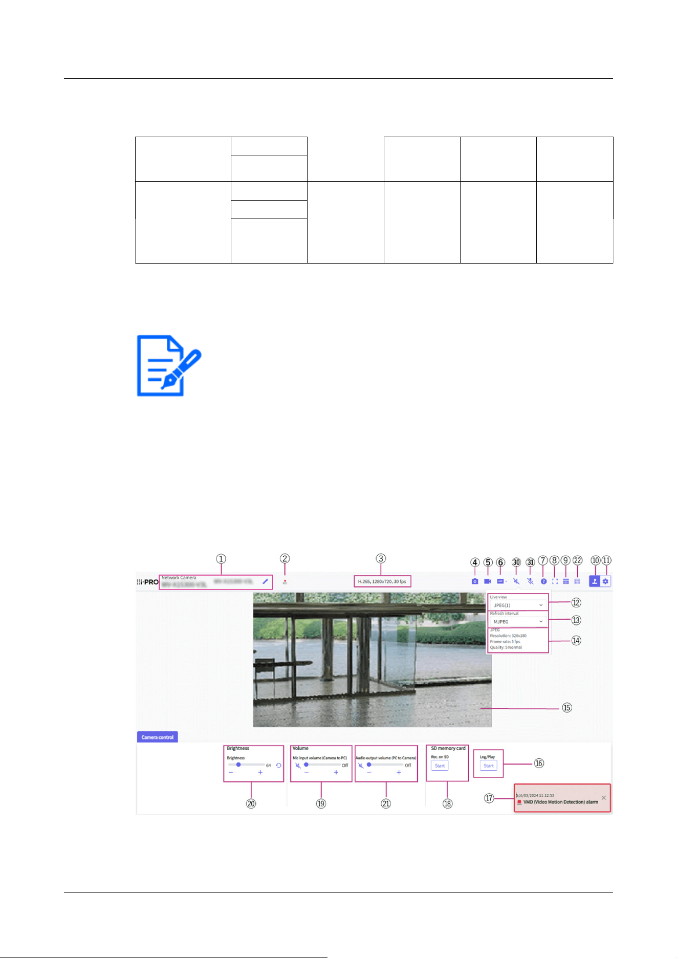
U-series camera with edge AI (Image capture size: 2MP)
(continued)
16:9 mode(25fps
mode)
640x360
320x180
4:3 mode(30fps
mode)
4:3 mode(25fps
mode)
1280x960 Up to 5
fps/4.2 fps
Up to 15
fps/12.5 fps
Up to 30
fps/25 fps
Up to 30
fps/25 fps
VGA
QVGA
[Note:]
・Buttons and settings displayed on the live image page can be changed depending
on the user's privileges. The user privileges are set in the [User mng.] [User
auth.].
→15.1 [User auth.] to configure user-authentication
・The design and layout of the screen may change.
・The items that can be set differ depending on the function of the model.
・Refer to the catalog specifications for the functions installed in each model.
2.3.2 About live image pages
2.3.2.1 Live image pages of Fixed Cameras
AI Outdoor IR Bullet Camera
2 Operation
2.3 Viewing images from a PC
49
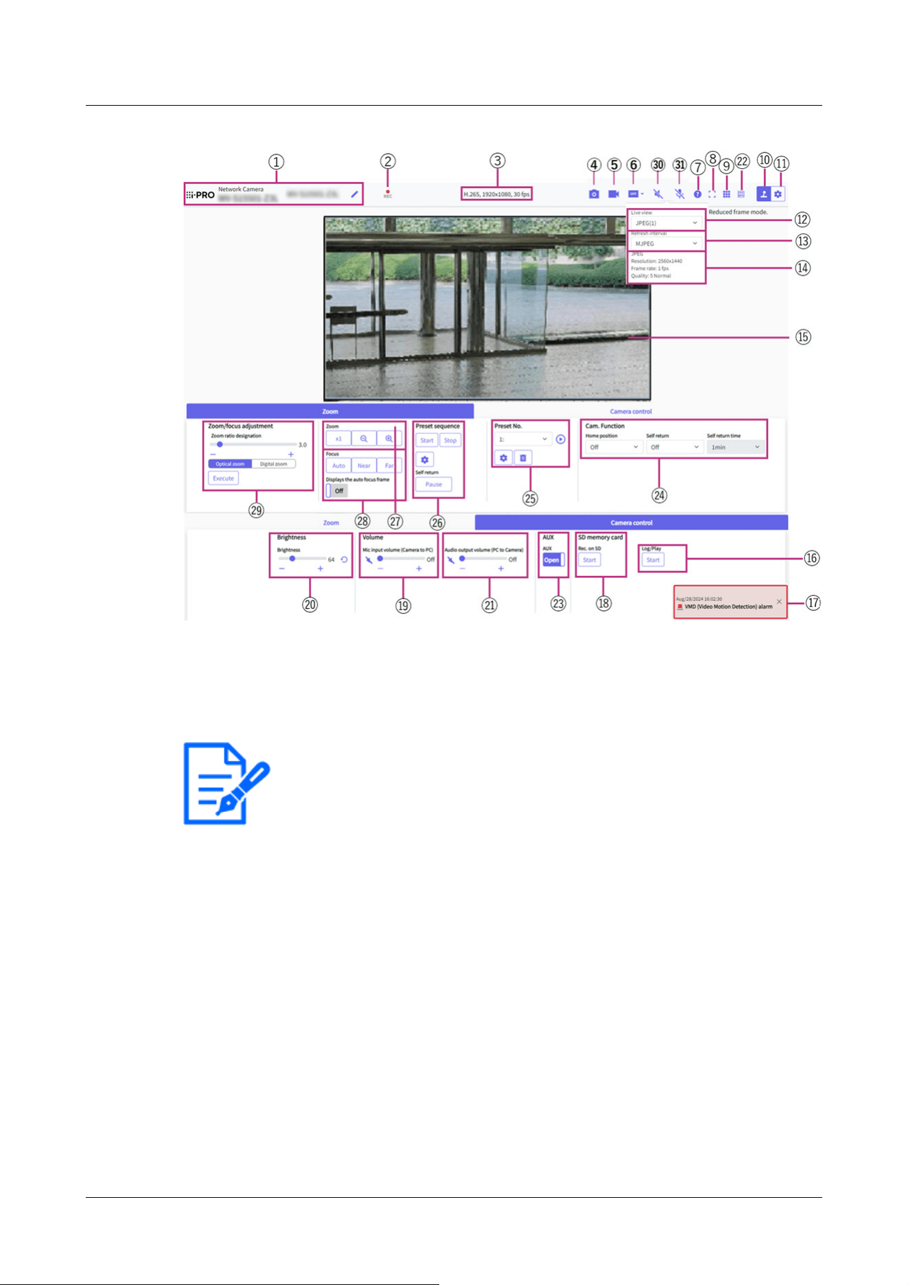
[Note:]
・The icon is not displayed on the following models.
Compact Dome cameras (U-series)
① [Camera title]
The title of the camera entered in [Camera title] on the [Basic] tab is displayed.
If you click the icon, the camera title becomes a text box and you can edit the string.
② [SD save status display]
Displays the storage status on the SD Memory Card.
When saving starts, the SD save status indicator turns red. The LED turns OFF when saving
stops.
This is displayed when the [Save trigger] in the Setup menu is set to [Manual save] or
[Schedule].
→9.2 [SD memory card] for setting SD Memory Cards
③ [View Stream Information
Displays the compression method, Image capture size, and frame rates of live video.
④ [Snap shot] button
2 Operation
2.3 Viewing images from a PC
50

[Note:]
・If it takes more than a certain period of time to acquire a snapshot depending on
the network environment, the image may not be displayed.
・If the specified Image capture size JPEG cannot be acquired, the Image capture
size JPEG images that can be acquired are displayed.
Therefore, if you snapshot a JPEG image and refer to it on a PC, the image size
may differ from the displayed image size.
・[New X Fixed-8M][New X Fixed-5M][AI Outdoor IR BulletX-8M][AI Outdoor IR
BulletX-5M] This function is not available when [Image capture mode] is set to
[60fps Mode] or [50fps Mode].
[Note:]
・It cannot be displayed on the multi-screen display.
A snapshot (one still image) is acquired and the image is displayed in a separate window.
Right-click on the image to save the image using the web browser function.
⑤ [Stream selection display] button
You can toggle between displaying and hiding popup displays on the stream selection screen.
In the streaming selection window, you can set the [Live only] etc.
⑥ [Before/after image comparison switching] button
Click the icon to acquire and display the still image. You can compare the acquired still
images as images before changing the image quality setting.
1:1:Displays the acquired still image and the latest image in the same size.
1:2:Displays the acquired still image and the latest image side by side so that the latest image
is twice the size.
Off:Only the latest image is displayed.
⑦ [Support] button
Click the Support button to display our Technical Information website in a separate window.
Our technical information website includes technical information, FAQ (Frequently Asked
Questions), etc.
⑧ [Full Screen] button
A new window opens displaying the full screen image.
⑨ [Grid display] button
You can switch the grid view on/off that can be used to align the this product when using
2 Operation
2.3 Viewing images from a PC
51

[Note:]
・When the Image capture size is [1280x720] or larger, the size of the browser
screen may be smaller than the actual size.
[Note:]
・The JPEG format (still image) update interval may not be updated at the specified
interval, depending on your network environment or PC.
Extension software.
Our Technical Information Website for adjusted sizes for each Extension software we sell and
provide<Control No.: C0320>It is listed.
⑩ [Camera Control Panel Display] button(
)
The camera control panel can be displayed or hidden. The camera control panel can be set to
[Brightness], etc.
⑪ [Set] buttons(
)
You can view or hide the setting panel.
→3 Setting
⑫ [Stream]-[Live only] pull-down menu
The image to be displayed in the main area can be selected from the following.
・[Stream(1)]/[Stream(2)]/[Stream(3)]/[Stream(4)]/[JPEG(1)]/[JPEG(2)]/[Multi-screen]
The main area images are displayed according to the settings in [Stream], [JPEG] and
[Multi-screen].
You can also configure the [Initial display stream] of the [Image] tabs to show the first
streams that appear when you are accessing the cameras. For [Multi-screen], you can set
the [Initial display] in the [Multi-screen] tab.
→10 [Image/Audio] for setting images and sound files
⑬ [Select Streams-[Refresh Rate] pull-down menu
This pull-down menu is displayed only when the JPEG image is displayed. Select how the
JPEG image is displayed.
• [MJPEG] Displays JPEG images consecutively (MJPEG: Motion JPEG).
Updates images in • [Refresh interval : 1s]/[Refresh interval : 3s]/[Refresh interval :
5s]/[Refresh interval : 10s]/[Refresh interval : 30s]/[Refresh interval : 60s]: JPEG format
(still image) at specified intervals.
⑭ [Stream]-[View Stream Info]
2 Operation
2.3 Viewing images from a PC
52

[Note:]
・Displays the value set in the stream. The actual bit rate and frame rate vary
depending on your network environment and PC.
[Note:]
・Users with low access levels may temporarily change the display but do not affect
the operation of the camera.
・When the shooting scene changes significantly depending on the PC, tiring (a
phenomenon in which a part of the screen is misaligned) may occur due to
constraints in the OS drawing process.
・When the data encryption function is enabled, the image cannot be viewed on the
live screen. Use the corresponding equipment.
・When a high zoom factor image is displayed, the clicked position may not be the
center of the image.
・As the tilt angle approaches 90 degrees, the difference between the specified
position and the actual direction of movement will become larger, and the
specified image angle may not be achieved.
・If the mouse is dragged to move to an angle that exceeds the rotational range of
the camera, the camera moves to the position where it can be operated, and then
the zoom factor is automatically adjusted.
Displays the settings of the compression method, Image capture size, bit rate, frame rate,
etc. of the live image.
⑮ [Main area]
Displays the camera image.
The current date and time are displayed according to the set [Time display format] and
[Date/time display format].
→9.1 [Basic] to perform basic settings
The set text is displayed on the screen. The number of lines is two.
When H.265 is displayed, when the bit rate is high, it may be displayed at the refresh
interval.
⑯ [Camera control panel]-[SD memory card]-[Log/Play] button
Clicking [Start] displays the log list and plays back the images stored on the SD Memory
Card. Please refer to the following for details of the log list and how to play back the image.
→2.7 Display the log list
2 Operation
2.3 Viewing images from a PC
53

[Note:]
・The alarm notification is not linked to the alarm notification operation such as
recording to the SD Memory Card or mail transfer. Check the respective
operation settings.
[Note:]
・When [Audio volume control mode] is set to [Adjust Mic input] in the Setup
menu, the volume cursor is not displayed when using [Audio recording] or [Audio
detection].
・When this product is restarted, the earpiece volume changed by the volume
cursor returns to the earpiece volume set in the [Audio] tabs of the setting
menus.
・On the screen, the volume cursor can be fine-tuned, but actually it is set to one
of four levels of volume.
・If you open multiple camera browsers simultaneously on the same PC, you cannot
hear the sound of the camera browser opened later. Access and check one by one.
・If network communication is unstable, voice reception may be stopped. In this
case, restart voice reception by turning on and off the earpiece button.
⑰ [Alarm notification]
When an alarm is generated, it is displayed as a popup. Clicking the [X] button resets the
output terminal and the display disappears.
→2.6 Operation when alarm is generated
⑱ [Camera control panel]-[SD memory card]-[Rec. on SD] button
This can only be set when [Save trigger] is set to [Manual save] on the [SD memory card]
tabs.
You can manually save images to SD Memory Cards by clicking [Start]. To manually save
images on the SD Memory Card, refer to the following.
→2.5 Manually save images on the SD memory card
⑲ [Camera control panel]-[Mic input volume (Camera to PC)]
This item can be set in the following settings.
• If [Audio input encoding format] is set to [AAC-LC]
Buttons, You can adjust the earpiece volume in four steps: [Off], [Low], [Middle], and
[High] by clicking on buttons or by moving the volume cursor.
Click the Listen button to turn on/off the earpiece voice (heard on PC).
→3.8 [Audio] for setting sound
2 Operation
2.3 Viewing images from a PC
54

→3.8 [Audio] for setting sound
・[Mic input volume (Camera to PC)] is not displayed during multicast delivery.
[Note:]
・Transmission voice can only be used when connected with HTTPS.
・If [Interactive(Half-duplex)] is set while one user is talking, the other user's
listening will be stopped and the earpiece button and the talk button will not be
operable. If set to [Interactive(Full-duplex)], other users will not be able to use
the call key.
・The maximum call duration per call is set on the [Audio] tabs of the video and
audio pages. The call stops after the set continuous call time. If you want to make
another call, click the call button.
・When the computer is restarted, the earpiece volume/voice volume changed by
the volume cursor will return to the earpiece volume/voice volume set in the
[Audio] tab of the image/voice page.
・On the screen, the volume cursor can be fine-tuned, but actually it is set to one
of four levels of volume.
→3.8 [Audio] for setting sound
・[Audio output volume (PC to Camera)] is not displayed during multicast delivery.
⑳ [Camera control panel]− [Brightness]
It can be adjusted from 0 to 255. Clicking the button brightens the image. Click the
button to darken the image. Click the button to return to the default settings.
㉑ [Camera control panel]-[Audio output volume (PC to Camera)]
This can only be set if [Audio transmission mode] is set to [Audio output] or [Interactive
(Full-duplex)] [Interactive(Half-duplex)] in the configuration menus.
Buttons, Click the button or move the volume cursor to adjust the voice volume in four
steps: Off/weak/medium/strong.
Click the talk button to turn on/off the talking voice (from PC).
→3.8 [Audio] for setting sound
㉒ Frame rate / bit rate display button
Displays the frame rate and bit rate of the stream currently displayed in the live display.
2 Operation
2.3 Viewing images from a PC
55

[Note:]
This button is not displayed if the live image meets any of the following conditions.
・JPEG stream display
・JPEG refresh interval
・Multi-screen
[Note:]
・The names of [AUX], [Open], and [Close] can be changed.
→14.3 [Alarm] to change the aux name
[Note:]
・If you want to move to the home position when the power is turned on, set
[HomePosition] to [Self return].
[Note:]
・If you want to perform the above operations when turning on the power, it is
convenient to use the self-return function.
・The self-return function works even when the setting menu is displayed.
・[Preset sequence] can be set only when preset sequence is set.
→12.3.2 Set the preset sequence setting (preset sequence setting screen)
㉓ [Camera control panel]-[AUX]
This setting is available only when [Terminal 3] of [Alarm] is set to [AUX output] in the
Advanced menu.
・[Open]: The aux terminal is open.
・[Close]: The aux terminal closes.
→7.3.2 Alarm: Sets terminal and operation detection (alarm setting screen)
㉔ [Zoom-Panel]-[Cam. Function]
[HomePosition]
The preset [Preset position] can be set as a [HomePosition]. When set to [HomePosition], [H]
is displayed next to the preset position number.
→12.3.1 Set the preset position (preset position setting screen)
[Self return]
When the time set by [Self return time] has elapsed after the manual operation is completed,
the camera can automatically return to the operation mode set by the camera.
2 Operation
2.3 Viewing images from a PC
56

[Note:]
・If the content of [Self return] operates at the time set by [Self return time] during
the preset sequence operation, the preset sequence operation stops.
[Self return time]
After the manual operation is completed, select the time before returning to the operation set
by [Self return].
㉕ [Zoom-panel]-[Preset No.]
Select the preset position from the pull-down menu and click the [Move] button to move the
camera's orientation to the preset position registered beforehand.
→12.3.2 Set the preset sequence setting (preset sequence setting screen)
[H] next to the number indicates [HomePosition]. Select [HomePosition] to move the
orientation of the camera to the home position.
→12.2 [Cam. Function] for setting the operation of cameras
If [Preset ID] is registered, the position name is displayed next to the number.
㉖ [Zoom-panel]-[Preset sequence]
Clicking [Start] starts the preset sequence operation.
When [Stop] is clicked, the preset sequence operation is stopped.
For details on how to execute [Preset sequence] in the Advanced Settings menu, refer to the
following.
→12.3.2 Set the preset sequence setting (preset sequence setting screen)
㉗ [Zoom panel]-[Zoom] buttons
Adjust the zoom manually.
・ :Adjust the zoom factor in the [Wide angle] direction.
・ :Zoom (magnification) 1.0 times.
・ :Adjust the zoom factor in the [Telescope] direction.
㉘ [Zoom panel]-[Focus] buttons
Adjust the focus manually with the buttons.
・[Auto]: Automatically adjusts focus.
・[Near]: Adjust the focus to the [Near].
・[Far]: Adjust the focus to the [Far].
・[Displays the auto focus frame]: [On] and draw a frame on the image to adjust the focus
(focus) to the frame.
2 Operation
2.3 Viewing images from a PC
57

[Note:]
・The following subjects cannot be focused with auto focus. Focus manually.
-A subject that is bright or reflects strong light
-Subject over water droplets or dirty glass
-Remote and nearby subjects mixed together
-Subjects (white walls, etc.) without contrast
-A horizontal subject, such as a blind-an oblique subject-a dark subject
[Note:]
・If the network communication is unstable, audio input may stop. In this case,
resume the mic input by turning the mic input button off and on.
・You can adjust the reception volume from the Camera control panel - [Mic input
volume (Camera to PC)].
[Note:]
・Audio transmission is available only when connected with HTTPS.
・When a user is using the audio transmission function with “Interactive(Half-
duplex)” selected, the receiver button and the transmission button will be
inoperable for the other users. When “Interactive(Full-duplex)” is selected, the
transmission button is inoperable for other users.
・The maximum duration of a single audio output is the audio output duration set in
the [Audio] tab on the “Image/Audio” page. Audio output stops when the
㉙ [Zoom-Panel]-[Zoom ratio designation]
・[Zoom ratio designation]: Adjusts the zoom and focus simultaneously. Adjusting the slider
bar changes the value next to the slider bar.
・[Optical zoom]: When the value set with the slider bar of [Zoom ratio designation] becomes
the optical zoom factor, the character color and background color change.
・[Digital zoom]: When the value set with the slider bar of [Zoom ratio designation] becomes
the digital zoom factor, the character color and background color change.
・[Execute]: Click to zoom in, and then use the auto focus function to automatically adjust
the focus to object in the center area of the display.
㉚ [Mic input] button
・Click the button to turn audio reception (Camera to PC) on/off.
㉛ [Audio output] button
・Click the button to turn on/off the talk audio (PC to Camera).
2 Operation
2.3 Viewing images from a PC
58
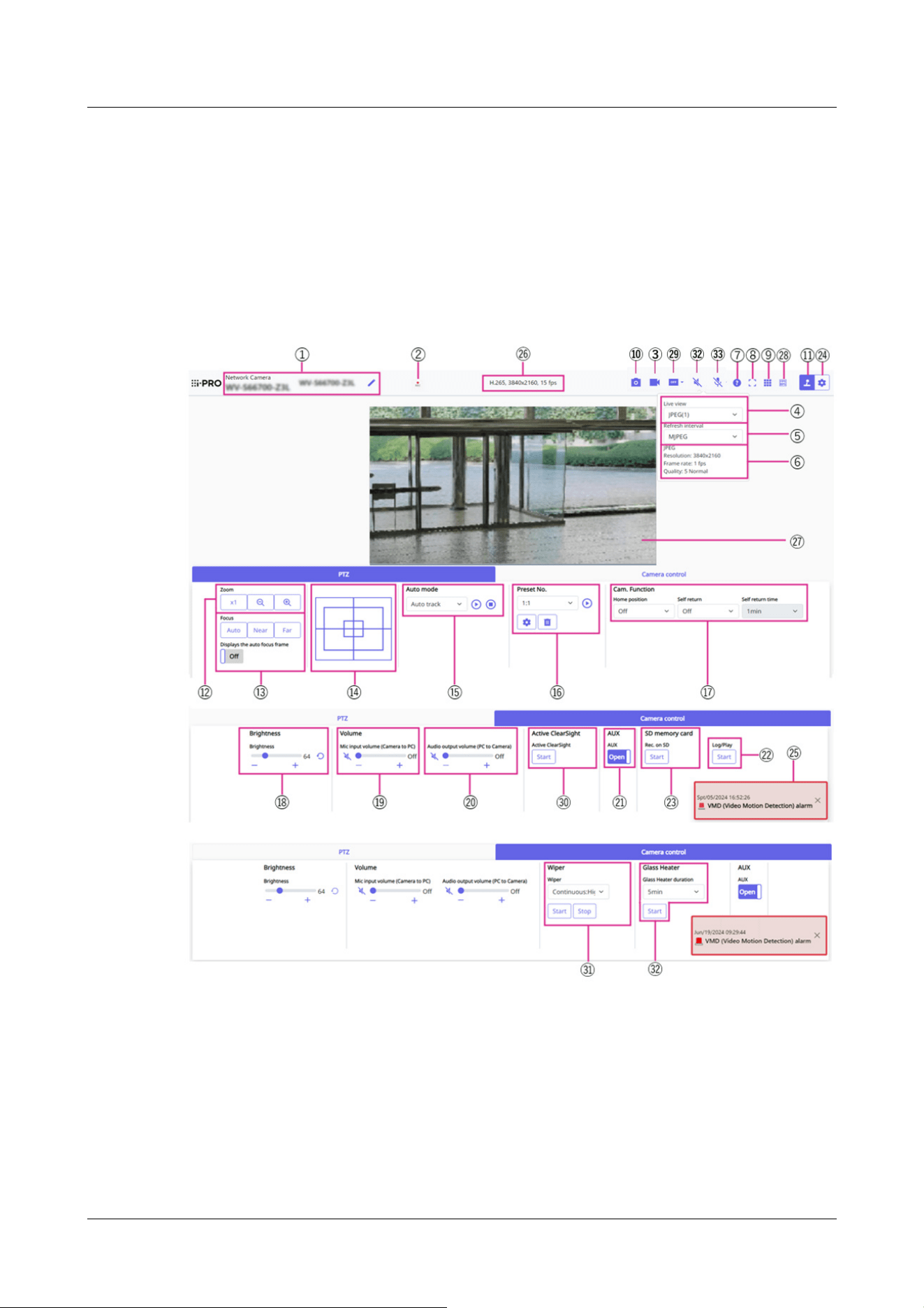
specified audio output duration has passed. To turn the audio transmission
function on, click the [Audio output] button again.
・You can adjust the audio output volume from the Camera control panel - [Audio
output volume (PC to Camera)].
2.3.2.2 Live image pages of the PTZ camera
①[Camera title]
The title of the camera entered in [Camera title] on the [Basic] tab is displayed.
If you click the icon, the camera title becomes a text box and you can edit the string.
②[SD save status display]
Displays the storage status on the SD Memory Card.
When saving starts, the SD save status indicator turns red. The LED turns OFF when saving
2 Operation
2.3 Viewing images from a PC
59

[Note:]
・When the resolution is [1280x720] or higher, the size of the browser screen may
be smaller than the actual size.
[Note:]
・The JPEG format (still image) update interval may not be updated at the specified
interval, depending on your network environment or PC.
stops.
This is displayed when the [Save trigger] in the Setup menu is set to [Manual] or [Schedule].
→9.2 [SD memory card] for setting SD Memory Cards
③[Stream selection display] button
You can toggle between displaying and hiding popup displays on the stream selection screen. In
the streaming selection window, you can set the [Live view] etc.
④ [Stream]-[Live only] pull-down menu
The image to be displayed in the main area can be selected from the following.
・[Stream(1)]/[Stream(2)]/[Stream(3)]/[Stream(4)]/[JPEG(1)]/[JPEG(2)]/[Multi-screen]
The main area images are displayed according to the settings in [Stream], [JPEG] and
[Multi-screen].
You can also configure the [Initial display stream] of the [Image] tabs to show the first
streams that appear when you are accessing the cameras. For [Multi-screen], you can set
the [Initial display] in the [Multi-screen] tab.
→10 [Image/Audio] for setting images and sound files
⑤[Select Streams-[Refresh Rate] pull-down menu
This pull-down menu is displayed only when the JPEG image is displayed. Select how the JPEG
image is displayed.
• [MJPEG] Displays JPEG images consecutively (MJPEG: Motion JPEG).
Updates images in [Refresh interval : 1s]/[Refresh interval : 3s]/[Refresh interval : 5s]/
[Refresh interval : 10s]/[Refresh interval : 30s]/[Refresh interval : 60s]: JPEG format (still
image) at specified intervals.
⑥[Stream]-[View Stream Info]
Displays the settings of the compression method, resolution, bit rate, frame rate, etc. of the live
image being displayed.
2 Operation
2.3 Viewing images from a PC
60

[Note:]
・Displays the value set in the stream. The actual bit rate and frame rate vary
depending on your network environment and PC.
[Note:]
・If it takes more than a certain period of time to acquire a snapshot depending on
the network environment, the image may not be displayed.
・If the specified resolution of JPEG cannot be acquired, the JPEG image with the
available resolution is displayed.
Therefore, if you snapshot a JPEG image and refer to it on a PC, the image size
may differ from the displayed image size.
⑦[Support] button
Click the Support button to display our Technical Information website in a separate window.
Our technical information website includes technical information, FAQ (Frequently Asked
Questions), etc.
⑧[Full Screen] button
A new window opens displaying the full screen image.
⑨[Grid display] button
You can switch the grid display ON/OFF that can be used to adjust the machine's position
when using the function extension software.
For the size of adjustments for each of the functional extensions we sell and provide, our
technical information website<Control No.: C0320>It is listed.
⑩[Snap shot] button
A snapshot (one still image) is acquired and the image is displayed in a separate window.
Right-click on the image to save the image using the web browser function.
⑪[Camera Control Panel Display] button( )
The camera control panel can be displayed or hidden. The camera control panel can be set to
[Brightness], etc.
⑫[PTZ panel]-[Zoom] buttons
Adjust the zoom manually.
・ :Adjust the zoom factor in the [Wide angle] direction.
・ :Zoom (magnification) 1.0 times.
・
:Adjust the zoom factor in the [Telescope] direction.
⑬[PTZ panel]-[Focus] buttons
2 Operation
2.3 Viewing images from a PC
61

[Note:]
・The following subjects cannot be focused with auto focus. Focus manually.
-A subject that is bright or reflects strong light
-Subject over water droplets or dirty glass
-Remote and nearby subjects mixed together
-Subjects (white walls, etc.) without contrast
-A horizontal subject, such as a blind-an oblique subject-a dark subject
Adjust the focus manually with the buttons.
• [Auto]: Automatically adjusts focus.
• [Near]: Adjust the focus to the [Near].
• [Far]: Adjust the focus to the [Far].
• [Displays the auto focus frame]: [On] and draw a frame on the image to adjust the focus (focus)
to the frame.
⑭[PTZ Panel]-Control pad
Left-click the pads and buttons to adjust the horizontal and vertical position of the image (pan
tilt).
The faster the camera operates, the faster the outside of the pad is clicked.
You can also drag and adjust the mouse. Zoom and focus by right-clicking.
Clicking on the upper half of the pad in the upper and lower directions will zoom in the
telephoto, and clicking on the lower half will zoom in the wide angle. Clicking on the left half in
the left and right directions will bring the focus (focus) close to you, and clicking on the right
half will bring it far away. You can also adjust the zoom by using the mouse wheel.
⑮[PTZ panel]-[Auto mode]
Selecting Operation from the pull-down menu starts the selected operation.
When panning, tilting, zooming, or focusing is performed, or when the operation set in [Self
return] or [Camera action on alarm] starts, it is also terminated.
→11.1 [Cam. Function] for setting the operation of cameras
→14.1 [Alarm] to set alarm operation
• [Auto track]: Automatically tracks objects when they are detected.
→11.3 Set auto-tracking (Auto-tracking screen)
• [Auto pan]: Automatically rotates the pre-set range between the start and end positions of the
pan. The pivot operation continues even after the zoom and focus operations (when the [x1]
button of the [Zoom] button is clicked, the pivot operation stops).
→11.2.3 Set auto pan (Auto pan setting screen)
• [Preset sequence 1]/[Preset sequence 2]/[Preset sequence 3] moves the pre-registered
2 Operation
2.3 Viewing images from a PC
62

[Note:]
・If the content of [Self return] operates at the time set by [Self return time] during
the auto mode operation, the auto mode operation stops.
→11.1 [Cam. Function] for setting the operation of cameras
[Note:]
・If you want to move to the home position when the power is turned on, set
[HomePosition] to [Self return].
[Note:]
・If you want to perform the above operations when turning on the power, it is
convenient to use the self-return function.
・The self-return function works even when the setting menu is displayed.
・[Patrol] can be set only when patrols are set.
→11.2.4 Set patrol (Patrol function setting screen)
preset positions from the lowest to the lowest.
→11.2.2 Set the preset sequence setting (preset sequence setting screen)
⑯[PTZ-panel]-[Preset]
Select the preset position from the pull-down menu and click the [Move] button to move the
camera's orientation to the preset position registered beforehand.
→11.2.2 Set the preset sequence setting (preset sequence setting screen)
[H] next to the number indicates [HomePosition]. Select [HomePosition] to move the
orientation of the camera to the home position.
→11.1 [Cam. Function] for setting the operation of cameras
If [Preset ID (0 – 9,A – Z)] is registered, the position name is displayed next to
the number.
⑰PTZ-Panel-[Cam. Function]
[HomePosition]
The preset [Preset position] can be set as a [HomePosition]. When set to [HomePosition], [H]
is displayed next to the preset position number.
→11.2.1 Set the preset position (preset position setting screen)
[Self return]
When the time set by [Self return time] has elapsed after the manual operation is completed,
the camera can automatically return to the operation mode set by the camera.
2 Operation
2.3 Viewing images from a PC
63

・Only [Patrol 1] can be set for “Patrol”. [Patrol 2], [Patrol 3] and [Patrol 4] are
unavailable.
→11.2.4 Set patrol (Patrol function setting screen)
・[Preset sequence] can be set only when preset sequence is set.
→11.2.2 Set the preset sequence setting (preset sequence setting screen)
[Note:]
・When [Audio volume control mode] is set to [Adjust Mic input] in the Setup
menu, the volume cursor is not displayed when using [Audio recording] or [Audio
detection].
・When the computer is restarted, the earpiece volume changed by the volume
cursor returns to the earpiece volume set in the [Audio] tabs of the setting
menus.
・On the screen, the volume cursor can be fine-tuned, but actually it is set to one
of four levels of volume.
・If you open multiple camera browsers simultaneously on the same PC, you cannot
hear the sound of the camera browser opened later. Access and check one by one.
・If network communication is unstable, voice reception may be stopped. In this
case, restart voice reception by turning on and off the earpiece button.
→3.8 [Audio] for setting sound
・[Mic input volume (Camera to PC)] is not displayed during multicast delivery.
[Self return time]
After the manual operation is completed, select the time before returning to the operation set
by [Self return].
⑱[Camera control panel]-[Brightness]
It can be adjusted from 0 to 255. Clicking the button brightens the image. Click the button
to darken the image. Click the button to return to the default settings.
⑲[Camera control panel]-[Mic input volume (Camera to PC)]
This item can be set in the following settings.
• If [Audio transmission mode] is set to [Mic input] or [Interactive(Full-duplex)] [Interactive
(Half-duplex)]
• If [Audio input encoding format] is set to [AAC-LC]
Buttons, You can adjust the earpiece volume in four steps: [Off], [Low], [Middle], and
[High] by clicking on buttons or by moving the volume cursor.
Click the Listen button to turn on/off the earpiece voice (heard on PC).
→3.8 [Audio] for setting sound
2 Operation
2.3 Viewing images from a PC
64

[Note:]
・Transmission voice can only be used when connected with HTTPS.
・If [Interactive(Half-duplex)] is set while one user is talking, the other user's
listening will be stopped and the earpiece button and the talk button will not be
operable. If set to [Interactive(Full-duplex)], other users will not be able to use
the call key.
・The maximum call duration per call is set on the [Audio] tabs of the video and
audio pages. The call stops after the set continuous call time. If you want to make
another call, click the call button.
・When the computer is restarted, the earpiece volume/voice volume changed by
the volume cursor will return to the earpiece volume/voice volume set in the
[Audio] tab of the image/voice page.
・On the screen, the volume cursor can be fine-tuned, but actually it is set to one
of four levels of volume.
→3.8 [Audio] for setting sound
・[Audio output volume (PC to Camera)] is not displayed during multicast delivery.
[Note:]
・The names of [AUX], [Open], and [Close] can be changed.
→14.3 [Alarm] to change the aux name
⑳[Camera control panel]-[Audio output volume (PC to Camera)]
This can only be set if [Audio transmission mode] is set to [Audio output] or [Interactive(Full-
duplex)] [Interactive(Half-duplex)] in the configuration menus.
Buttons, Click the button or move the volume cursor to adjust the voice volume in four
steps: Off/weak/medium/strong.
Click the talk button to turn on/off the talking voice (from PC).
→3.8 [Audio] for setting sound
㉑[Camera control panel]-[AUX]
This setting is available only when [Terminal 3] of [Alarm] is set to [AUX output] in the
Advanced menu.
・[Open]: The aux terminal is open.
・[Close]: The aux terminal closes.
→7.3.2 Alarm: Sets terminal and operation detection (alarm setting screen)
㉒[Camera control panel]-[SD memory card]-[Log/Play] button
2 Operation
2.3 Viewing images from a PC
65

[Note:]
・The alarm notification is not linked to the alarm notification operation such as
recording to the SD Memory Card or mail transfer. Check the respective
operation settings.
Clicking [Start] displays the log list and plays back the images stored on the SD Memory Card.
Please refer to the following for details of the log list and how to play back the image.
→2.7 Display the log list
㉓[Camera control panel]-[SD memory card]-[Rec. on SD] button
This can only be set when [Save trigger] is set to [Manual save] on the [SD memory card] tabs.
You can manually save images to SD Memory Cards by clicking [Start]. To manually save
images on the SD Memory Card, refer to the following.
→2.5 Manually save images on the SD memory card
㉔[Set] buttons(
)
You can view or hide the setting panel.
→3 Setting
㉕[Alarm notification]
When an alarm is generated, it is displayed as a popup. Clicking the [X] button resets the
output terminal and the display disappears.
→2.6 Operation when alarm is generated
㉖[View Stream Information]
Displays the compression method, resolution, and frame rate of live video.
㉗[Main area]
Displays the camera image.
The current date and time are displayed according to the set [Time display format] and
[Date/time display format].
→9.1 [Basic] to perform basic settings
The set text is displayed on the screen. The number of lines is two.
When H.265 is displayed, when the bit rate is high, it may be displayed at the refresh interval.
In the main area, clicking the desired position for the center of the field angle moves the
camera's direction to the center of the clicked position.
If you select the area you want to view by dragging the mouse, the camera will move to a
position centered on the selected area and the zoom factor will be automatically adjusted.
You can also adjust the zoom in the mouse wheel operation.
Right-clicking in the main area starts automatic tracking of objects in the clicked position.
Depending on the object to be tracked and the surrounding environment, the watch may not
2 Operation
2.3 Viewing images from a PC
66

[Note:]
・Users with low access levels may temporarily change the display but do not affect
the operation of the camera.
・When the shooting scene changes significantly depending on the PC, tiring (a
phenomenon in which a part of the screen is misaligned) may occur due to
constraints in the OS drawing process.
・When the data encryption function is enabled, the image cannot be viewed on the
live screen. Use the corresponding equipment.
・When a high zoom factor image is displayed, the clicked position may not be the
center of the image.
・As the tilt angle approaches 90 degrees, the difference between the specified
position and the actual direction of movement will become larger, and the
specified image angle may not be achieved.
・If the mouse is dragged to move to an angle that exceeds the rotational range of
the camera, the camera moves to the position where it can be operated, and then
the zoom factor is automatically adjusted.
[Note:]
This button is not displayed if the live image meets any of the following conditions.
・JPEG stream display
・JPEG refresh interval
・Multi-screen
operate properly.
㉘Frame rate / bit rate display button
Displays the frame rate and bit rate of the stream currently displayed in the live display.
㉙ [Before/after image comparison switching] button
Click the icon to acquire and display the still image. You can compare the acquired still
images as images before changing the image quality setting.
1:1:Displays the acquired still image and the latest image in the same size.
1:2:Displays the acquired still image and the latest image side by side so that the latest image
is twice the size.
Off:Only the latest image is displayed.
2 Operation
2.3 Viewing images from a PC
67

[Note:]
・It cannot be displayed on the multi-screen display.
[Note:]
・During washer operations, [Wiper] [Start] and [Stop], pan/tilt/zoom/focus
control, [Auto mode] [Start], preset action, and Settings in [Image/Position] Tab
cannot be operated.
・When [Continuous:High] or [Continuous:Low] is selected and the [Start] button
is clicked, the wiper will stop after a maximum of 5 minutes from when the [Start]
button was clicked.
・During pan/tilt/zoom controls, [Start] may not be able to be operated for the
washer.
・If the wiper or washer operations are started during auto tracking operations, the
wiper may be detected and tracked.
㉚ [Camera control panel]-[Active ClearSight]
Clicking [Start] starts the camera's PAN/TILT to move at the same time. The camera moves
a few times back and forth between the specified angles to remove raindrops.
For details on how to execute [Active ClearSight] in the Advanced Settings menu, refer to
the following.
→18.3 [Status] for checking the status
㉛ [Camera control panel]-[Wiper]
Selecting Operation from the pull-down menu starts the selected operation.
・[Continuous:High]:The wiper wipes the front glass once every 6 seconds.
・[Continuous:Low]:The wiper wipes the front glass once every 11 seconds.
・[1shot]:The wiper wipes the front glass 4 times.
・[Washer]:Install a washer nozzle on the camera body. Spray washer liquid on the front glass
from the installed washer nozzle and wipe it off automatically with a wiper. [Washer] can be
selected only when [Washer Control] is selected in [Relay Out] on the Basic page of
Advanced Settings.
→9.1 [Basic] to perform basic settings
㉜ [Camera control panel]-[Glass Heater]
When the front glass becomes cloudy and the image becomes difficult to see in a low
temperature environment, you can use this function to make the image easier to see.
2 Operation
2.3 Viewing images from a PC
68

[Note:]
・If the camera gets hot, [Glass Heater] may stop automatically.
[Note:]
・If the network communication is unstable, audio input may stop. In this case,
resume the mic input by turning the mic input button off and on.
・You can adjust the reception volume from the Camera control panel - [Mic input
volume (Camera to PC)].
[Note:]
・Audio transmission is available only when connected with HTTPS.
・When a user is using the audio transmission function with “Interactive(Half-
duplex)” selected, the receiver button and the transmission button will be
inoperable for the other users. When “Interactive(Full-duplex)” is selected, the
transmission button is inoperable for other users.
・The maximum duration of a single audio output is the audio output duration set in
the [Audio] tab on the “Image/Audio” page. Audio output stops when the
specified audio output duration has passed. To turn the audio transmission
function on, click the [Audio output] button again.
・You can adjust the audio output volume from the Camera control panel - [Audio
output volume (PC to Camera)].
Select a time from the pull-down menu and press [Start] to start the operation for the
selected time.
[5min]/ [10min]/ [15min]/ [20 min]/ [30min]/ [45 min]/ [60min]/ [90 min]/ [120 min]/
[180 min]
㉝ [Mic input] button
・Click the button to turn audio reception (Camera to PC) on/off.
㉞ [Mic input] button
・Click the button to turn audio reception (Camera to PC) on/off.
2 Operation
2.3 Viewing images from a PC
69
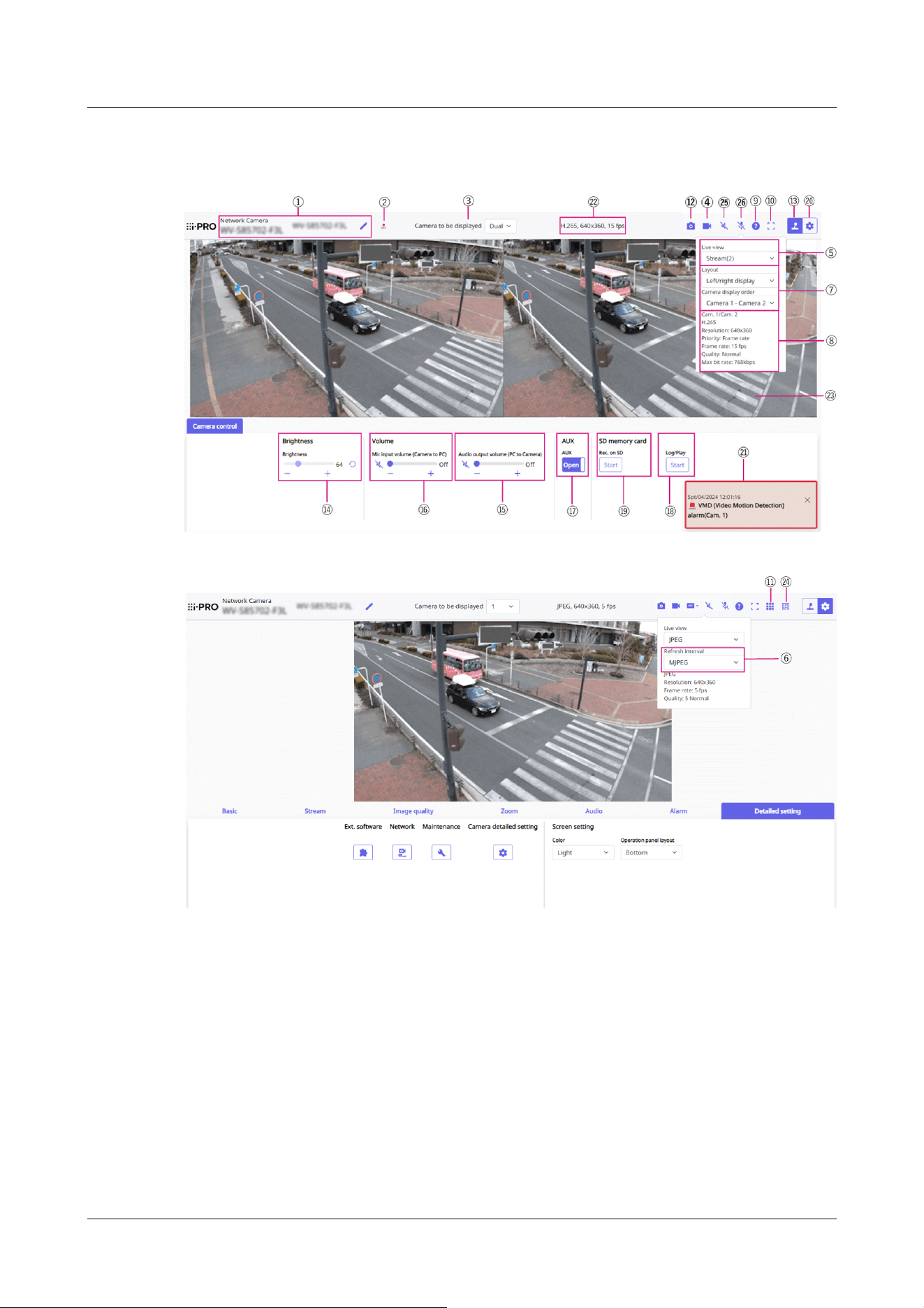
2.3.2.3 Live image pages of Multi-directional Cameras
①[Camera title]
The title of the camera entered in [Camera title] on the [Basic] tab is displayed.
If you click the icon, the camera title becomes a text box and you can edit the string.
②[SD Storage Status Display]
Displays the storage status on the SD Memory Card.
When saving starts, the SD save status indicator turns red. The LED turns OFF when saving
stops.
This is displayed when the [Save trigger] in the Setup menu is set to [Manual] or [Schedule].
→9.2 [SD memory card] for setting SD Memory Cards
2 Operation
2.3 Viewing images from a PC
70

[Note:]
・This item is not displayed when [Image capture mode] is in Dual mode.
[Note:]
・This item is not displayed when [Image capture mode] is in Dual mode.
・When 1 or 2 is selected, the size of the browser may be smaller than the actual
size, depending on the size of the browser when the Image capture size is
[1280x720] or larger, or when [Image capture mode] is Dual mode. When [Dual] is
selected, the size of the browser may be smaller than the actual size of the
browser in any Image capture size.
③[Camera to be displayed]
Select the camera to be displayed in the main area.
• [Dual]: Displays images of cameras 1 and 2 in two sections.
•1: Displays camera 1 images.
•2: Displays camera 2 images.
④[Stream Selection Display] button
You can toggle between displaying and hiding popup displays on the stream selection screen. In
the streaming selection window, you can set the [Live view] etc.
⑤[Select Streams]-[Live view] pull-down menu
The image to be displayed in the main area can be selected from the following.
[Dual]When selected: [Streams(2)]/ [JPEG]
When 1 or 2 is selected: [Stream(1)]/ [Stream(2)]/[JPEG]
The main area image is displayed according to the settings in streams (1) to (2) and JPEG.
You can also configure the [Initial display stream] of the [Stream] tabs to show the first streams
that appear when you are accessing the cameras.
→3.3 [Stream] for setting images
⑥[Select Streams]-[Refresh Rate] pull-down menu
This pull-down menu is displayed only when the JPEG image is displayed. Select how the JPEG
image is displayed.
[MJPEG]:Displays a JPEG image as a series (MJPEG: Motion JPEG).
[Refresh interval : 1s]/[Refresh interval : 3s]/[Refresh interval : 5s]/[Refresh interval :
10s]/[Refresh interval : 30s]/ [Refresh interval : 60s]:Updates JPEG images (still images) at
specified intervals.
2 Operation
2.3 Viewing images from a PC
71

[Note:]
・The JPEG format (still image) update interval may not be updated at the specified
interval, depending on your network environment or PC.
・If [Dual] is selected in the [Live only] pull-down menu, [Refresh interval : 1s] and
[Refresh interval : 3s] cannot be selected.
[Notice:]
When [Dual] is selected in [Layout], select [Camera 1-Camera 2] or [Camera
2-Camera 1] in the order in which the cameras are displayed in [Camera display
order].
[Note:]
・Displays the value set in the stream. The actual bit rate and frame rate vary
depending on your network environment and PC.
⑦[Select Streams]-[Layout] pull-down menu
This pull-down menu is displayed only when it is displayed in [Dual].
Select the display layout of the camera image to be displayed in the main area from the
left/right/up/down view.
⑧[Select stream]-[View Stream Information]
Displays the settings of the compression method, resolution, bit rate, frame rate, etc. of the live
image being displayed.
⑨[Support button]
Click the Support button to display our Technical Information website in a separate window.
Our technical information website includes technical information, FAQ (Frequently Asked
Questions), etc.
⑩[Full Screen Display Button]
A new window opens displaying the full screen image.
⑪[Grid display] buttons
You can switch the grid display ON/OFF that can be used to adjust the machine's position
when using the function extension software.
For the size of adjustments for each of the functional extensions we sell and provide, our
technical information website<Control No.: C0320>It is listed.
⑫[Snapshot button]
2 Operation
2.3 Viewing images from a PC
72

[Note:]
・If it takes more than a certain period of time to acquire a snapshot depending on
the network environment, the image may not be displayed.
・If the specified resolution of JPEG cannot be acquired, the JPEG image with the
available resolution is displayed. Therefore, if you snapshot a JPEG image and
refer to it on a PC, the image size may differ from the displayed image size.
[Note:]
・This item is not displayed when [Image capture mode] is in Dual mode.
[Note:]
・Transmission voice can only be used when connected with HTTPS.
・If [Interactive(Half-duplex)] is set while one user is talking, the other user's
listening will be stopped and the earpiece button and the talk button will not be
operable. If set to [Interactive(Full-duplex)], other users will not be able to use
the call key.
・The maximum call duration per call is set on the [Audio] tabs of the video and
A snapshot (one still image) is acquired and the image is displayed in a separate window.
Right-click on the image to save the image using the web browser function.
⑬[Camera Control Panel View button]( )
The camera control panel can be displayed or hidden. The camera control panel can be set to
[Brightness], etc.
⑭[Camera Control Panel]-[Brightness]
It can be adjusted from 0 to 255. Clicking the button brightens the image. Click the button
to darken the image. Click the button to return to the default settings. This cannot be set
when [Dual] is displayed.
⑮[Camera Control Panel]-[Audio output volume (PC to Camera)]
This can only be set if [Audio transmission mode] is set to [Audio output] or [Interactive(Full-
duplex)] [Interactive(Half-duplex)] in the configuration menus.
→3.8 [Audio] for setting sound
Buttons, By clicking on the buttons or by moving the volume cursors, you can adjust the
volume of the call by four levels: [Off], [Low], [Middle] and [High].
Click the talk button to turn on/off the talking voice (from PC).
2 Operation
2.3 Viewing images from a PC
73

audio pages. The call stops after the set continuous call time. If you want to make
another call, click the call button.
・When the computer is restarted, the earpiece volume/voice volume changed by
the volume cursor will return to the earpiece volume/voice volume set in the
[Audio] tab of the image/voice page.
→3.8 [Audio] for setting sound
・On the screen, the volume cursor can be fine-tuned, but actually it is set to one
of four levels of volume.
・[Audio output volume (PC to Camera)] is not displayed during multicast delivery.
[Note:]
・When [Audio volume control mode] is set to [Adjust Mic input] in the Setup
menu, the volume cursor is not displayed when using [Audio recording] or [Audio
detection].
→3.8 [Audio] for setting sound
・When the computer is restarted, the earpiece volume changed by the volume
cursor returns to the earpiece volume set in the [Audio] tabs of the setting
menus.
→3.8 [Audio] for setting sound
・On the screen, the volume cursor can be fine-tuned, but actually it is set to one
of four levels of volume.
・If you open multiple camera browsers simultaneously on the same PC, you cannot
hear the sound of the camera browser opened later. Access and check one by one.
・If network communication is unstable, voice reception may be stopped. In this
case, restart voice reception by turning on and off the earpiece button.
・[Mic input volume (Camera to PC)] is not displayed during multicast delivery.
⑯[Camera Control Panel-[Mic input volume (Camera to PC)]
This item can be set in the following settings.
→3.8 [Audio] for setting sound
• If [Audio transmission mode] is set to [Mic input] or [Interactive(Full-duplex)] [Interactive
(Half-duplex)]
• If [Audio input encoding format] is set to [AAC-LC]
Buttons, You can adjust the earpiece volume in four steps: [Off], [Low], [Middle], and
[High] by clicking on buttons or by moving the volume cursor.
Click the Listen button to turn on/off the earpiece voice (heard on PC).
2 Operation
2.3 Viewing images from a PC
74

[Note:]
・The names of [AUX], [Open], and [Close] can be changed.
→14.3 [Alarm] to change the aux name
[Note:]
・The alarm notification is not linked to the alarm notification operation such as
recording to the SD Memory Card or mail transfer. Check the respective
operation settings.
⑰[Camera Control Panel]-[AUX]
This setting is available only when [Terminal 3] of [Alarm] is set to [AUX output] in the
Advanced menu.
→7.3.2 Alarm: Sets terminal and operation detection (alarm setting screen)
[Open]:The AUX terminal is open.
[Close]:The AUX terminal will be closed.
⑱[Camera Control Panel]-[Playback of recording (Log disp.)]
Clicking [Start] displays the log list and plays back the images stored on the SD Memory Card.
Please refer to the following for details of the log list and how to play back the image.
→2.7 Display the log list
⑲[Camera Control Panel]-[Record/Play (SD Memory Card)]
This can only be set when [Save trigger] is set to [Manual save] on the [SD memory card] tabs.
You can manually save images to SD Memory Cards by clicking [Start]. To manually save
images on the SD Memory Card, refer to the following.
→2.5 Manually save images on the SD memory card
⑳[Set] buttons( )
You can view or hide the setting panel.
→3 Setting
㉑[Alarm notification]
When an alarm is generated, it is displayed as a popup. Clicking the [X] button resets the
output terminal and the display disappears.
→2.6 Operation when alarm is generated
㉒[View Stream Information]
Displays the compression method, resolution, and frame rate of live video.
㉓[Main area]
Displays the camera image.
2 Operation
2.3 Viewing images from a PC
75

[Note:]
・Users with low access levels may temporarily change the display but do not affect
the operation of the camera.
・When the shooting scene changes significantly depending on the PC, tiring (a
phenomenon in which a part of the screen is misaligned) may occur due to
constraints in the OS drawing process.
・When the data encryption function is enabled, the image cannot be viewed on the
live screen. Use the corresponding equipment.
[Note:]
This button is not displayed if the live image meets any of the following conditions.
・JPEG stream display
・JPEG refresh interval
・[Dual] display
[Note:]
・If the network communication is unstable, audio input may stop. In this case,
resume the mic input by turning the mic input button off and on.
・You can adjust the reception volume from the Camera control panel - [Mic input
volume (Camera to PC)].
The current date and time are displayed according to the set [Time display format] and
[Date/time display format].
→9.1 [Basic] to perform basic settings
The set text is displayed on the screen. The number of lines is two.
When H.265 is displayed, when the bit rate is high, it may be displayed at the refresh interval.
㉔Frame rate / bit rate display button
Displays the frame rate and bit rate of the stream currently displayed in the live display.
㉕[Mic input] button
・Click the button to turn audio reception (Camera to PC) on/off.
㉖[Audio output] button
・Click the button to turn on/off the talk audio (PC to Camera).
2 Operation
2.3 Viewing images from a PC
76
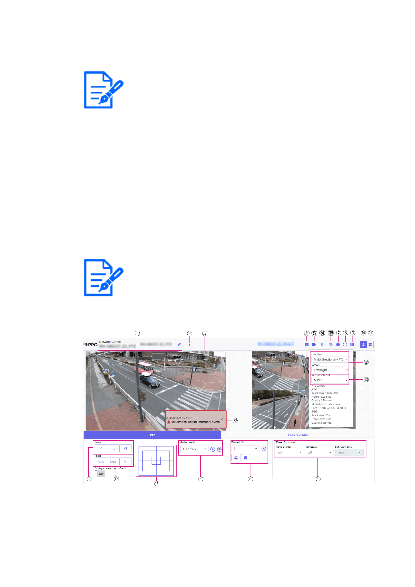
[Note:]
・Audio transmission is available only when connected with HTTPS.
・When a user is using the audio transmission function with “Interactive(Half-
duplex)” selected, the receiver button and the transmission button will be
inoperable for the other users. When “Interactive(Full-duplex)” is selected, the
transmission button is inoperable for other users.
・The maximum duration of a single audio output is the audio output duration set in
the [Audio] tab on the “Image/Audio” page. Audio output stops when the
specified audio output duration has passed. To turn the audio transmission
function on, click the [Audio output] button again.
・You can adjust the audio output volume from the Camera control panel - [Audio
output volume (PC to Camera)].
[Note:]
・[MULTI_PTZ] The live image pages for each camera are displayed by accessing
the IP addresses set for the PTZ camera and the Multi-directional camera.
2.3.2.4 Live image pages of Multi-directional/PTZ integrated cameras
PTZ camera
2 Operation
2.3 Viewing images from a PC
77
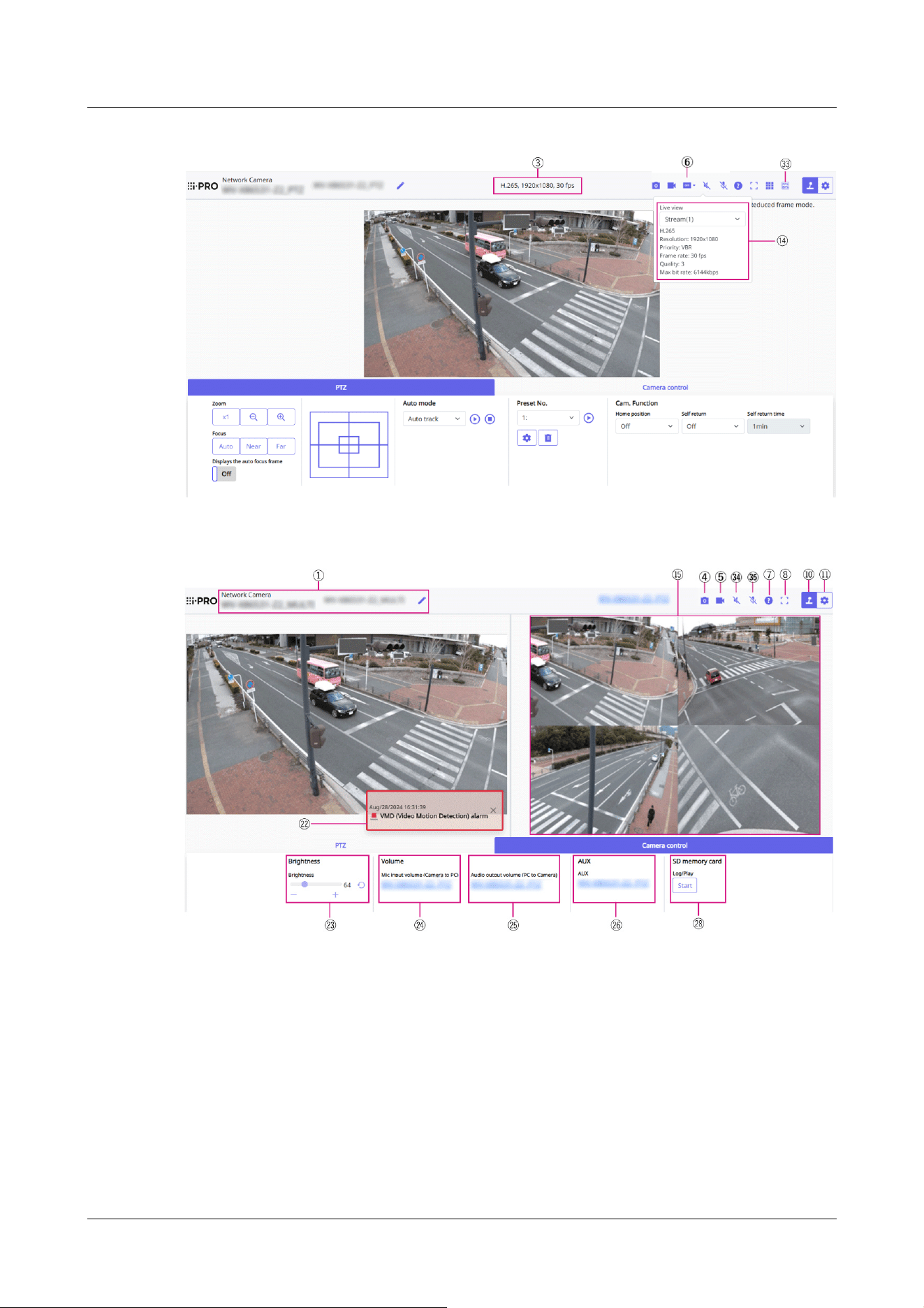
Multi-directional camera
2 Operation
2.3 Viewing images from a PC
78
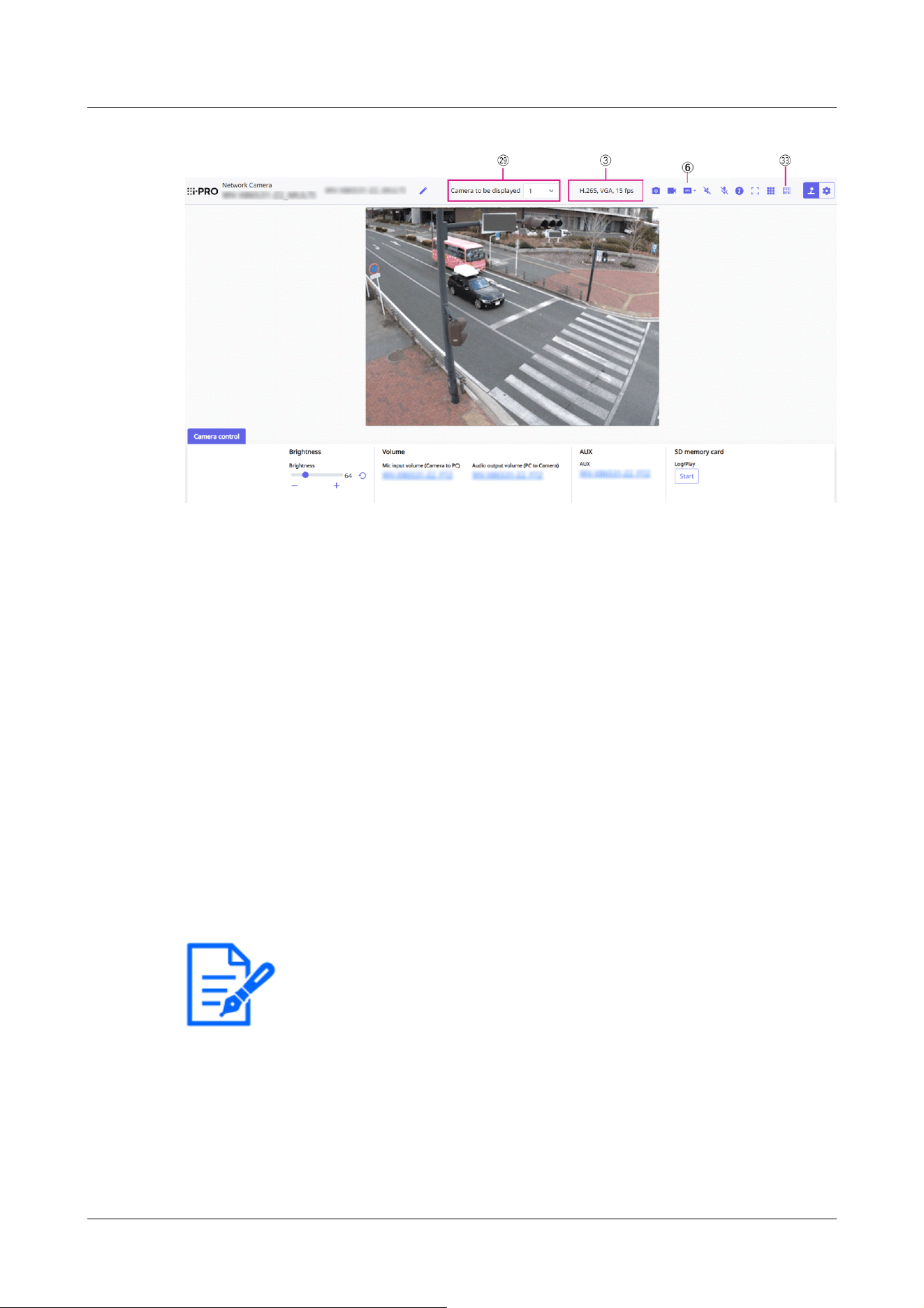
[Note:]
・If it takes more than a certain period of time to acquire a snapshot depending on
the network environment, the image may not be displayed.
・If the specified resolution of JPEG cannot be acquired, the JPEG image with the
available resolution is displayed.
Therefore, if you snapshot a JPEG image and refer to it on a PC, the image size
may differ from the displayed image size.
①[Camera title]
The title of the camera entered in [Camera title] on the [Basic] tab is displayed.
If you click the icon, the camera title becomes a text box and you can edit the string.
②[SD Storage Status Display]
Displays the storage status on the SD Memory Card.
When saving starts, the SD save status indicator turns red. The LED turns OFF when saving
stops.
This is displayed when the [Save trigger] in the Setup menu is set to [Manual] or [Schedule].
→9.2 [SD memory card] for setting SD Memory Cards
③[View Stream Information]
Displays the compression method, resolution, and frame rate of live video.
④[Snapshot button]
A snapshot (one still image) is acquired and the image is displayed in a separate window.
Right-click on the image to save the image using the web browser function.
⑤[Stream Selection Display button]
2 Operation
2.3 Viewing images from a PC
79

You can toggle between displaying and hiding popup displays on the stream selection screen. In
the streaming selection window, you can set the [Live view] etc.
⑥[Before/after image comparison toggle button]
Click the icon to acquire and display the still image. You can compare the acquired still images
as images before changing the image quality setting.
[ ][1] Displays the downloaded still image and the latest image in the same size.
[ ][1]:The latest image is doubled in size between the downloaded still image and the latest
image.
[
][View]: Only the latest image is displayed.
⑦[Support button]
Click the Support button to display our Technical Information website in a separate window.
Our technical information website includes technical information, FAQ (Frequently Asked
Questions), etc.
⑧[Full Screen Display Button]
A new window opens displaying the full screen image.
⑨[Grid display] buttons
You can switch the grid display ON/OFF that can be used to adjust the machine's position
when using the function extension software.
For the size of adjustments for each of the functional extensions we sell and provide, our
technical information website<Control No.: C0320>It is listed.
⑩[Camera Control Panel View] button( )
The camera control panel can be displayed or hidden. The camera control panel can be set to
[Brightness], etc.
⑪[Set] buttons(
)
You can view or hide the setting panel.
→3 Setting
⑫[Select Streams]-[Live view] pull-down menu
The image to be displayed in the main area can be selected from the following.
PTZ camera
[Multi-directional + PTZ/[Stream(1)]/[Stream(2)]/[Stream(3)]/[Stream(4)]/JPEG(1)/JPEG(2)
Multi-directional camera
[Camera to be displayed]When [Quad] [Triple] is selected:[Multi-directional + PTZ]/[Stream
(2)]/JPEG
[Camera to be displayed]When 1, 2, 3, or 4 are selected:[Multi-directional + PTZ]/[Stream(1)]
/[Stream(2)]/JPEG
2 Operation
2.3 Viewing images from a PC
80

[Note:]
・When the resolution is [1280x720] or higher, the size of the browser screen may
be smaller than the actual size.
・[MULTI] This item is not displayed when [Image capture mode] is in quad mode.
・[MULTI] When selecting 1, 2, 3, or 4, if the resolution is [1280x720] or higher or
[Image capture mode] is Quad-mode, the size of the browser screen may be
smaller than the actual size. When [Quad] [Triple] is selected, the size of the
browser screen may be smaller than the actual size at any resolution.
[Note:]
・The JPEG format (still image) update interval may not be updated at the specified
interval, depending on your network environment or PC.
・[MULTI] When [Quad] [Triple] is selected in the [Live view] pull-down menu,
[Refresh interval : 1s] and [Refresh interval : 3s] cannot be selected.
[Note:]
・Displays the value set in the stream. The actual bit rate and frame rate vary
depending on your network environment and PC.
The main area image is displayed according to the settings in the stream and JPEG.
You can also configure the [Initial display stream] of the [Image] tabs to show the first
streams that appear when you are accessing the cameras.
→3.3 [Stream] for setting images
⑬[Select Streams]-[Refresh Rate] pull-down menu
This pull-down menu is displayed only when the JPEG image is displayed. Select how the JPEG
image is displayed.
MJPEG:Displays a JPEG image as a series (MJPEG: Motion JPEG).
[Still image updates: 1 second]/[Refresh interval : 3s]/[Refresh interval : 5s]/[Refresh interval :
10s]/[Refresh interval : 30s]/ [Refresh interval : 60s]:Updates JPEG images (still images) at
specified intervals.
⑭[Select stream]-[View stream information]
Displays the settings of the compression method, resolution, bit rate, frame rate, etc. of the live
image being displayed.
⑮[Main area]
Displays the camera image.
2 Operation
2.3 Viewing images from a PC
81

[Note:]
・Users with low access levels may temporarily change the display but do not affect
the operation of the camera.
・When the shooting scene changes significantly depending on the PC, tiring (a
phenomenon in which a part of the screen is misaligned) may occur due to
constraints in the OS drawing process.
・When the data encryption function is enabled, the image cannot be viewed on the
live screen. Use the corresponding equipment.
・When a high zoom factor image is displayed, the clicked position may not be the
center of the image.
・As the tilt angle approaches 90 degrees, the difference between the specified
position and the actual direction of movement will become larger, and the
specified image angle may not be achieved.
・If the mouse is dragged to move to an angle that exceeds the rotational range of
the camera, the camera moves to the position where it can be operated, and then
the zoom factor is automatically adjusted.
The current date and time are displayed according to the set [Time display format] and
[Date/time display format].
→9.1 [Basic] to perform basic settings
The set text is displayed on the screen. The number of lines is two.
When H.265 is displayed, when the bit rate is high, it may be displayed at the refresh interval.
⑯[PTZ-Panel]-[Zoom] Buttons
Adjust the zoom manually.
:Adjust the zoom factor in the [Wide angle] direction.
:Zoom (magnification) 1.0 times.
:Adjust the zoom factor in the [Telescope] direction.
⑰[PTZ-panel]-[Focus]
Adjust the focus manually with the buttons.
[Auto]:Automatically adjust focus.
[Near]:Adjust the focus to the [Near].
[Far]:Adjust the focus to the [Far].
[Displays the auto focus frame]:When you draw a frame with the image [On], adjust the focus
(focus) to match the frame.
2 Operation
2.3 Viewing images from a PC
82

[Note:]
・The following subjects cannot be focused with auto focus. Focus manually.
A subject that is bright or reflects strong light
-Subject over water droplets or dirty glass
Remote and nearby subjects mixed together
-Subjects (white walls, etc.) without contrast
A horizontal subject, such as a blind-an oblique subject-a dark subject
⑱[PTZ panel-[Control pad]
Left-click the pads and buttons to adjust the horizontal and vertical position of the image (pan
tilt).
The faster the camera operates, the faster the outside of the pad is clicked.
You can also drag and adjust the mouse. Zoom and focus by right-clicking.
Clicking on the upper half of the pad in the upper and lower directions will zoom in the
telephoto, and clicking on the lower half will zoom in the wide angle. Clicking on the left half in
the left and right directions will bring the focus (focus) close to you, and clicking on the right
half will bring it far away. You can also adjust the zoom by using the mouse wheel.
⑲[PTZ-panel]-[Auto mode]
Selecting Operation from the pull-down menu starts the selected operation.
When panning, tilting, zooming, or focusing is performed, or when the operation set in [Self
return] or [Camera action on alarm] starts, it is also terminated.
→11.1 [Cam. Function] for setting the operation of cameras
→14.4 [Alarm] to set alarm linkage operation
[Automatic Tracking]:When a pre-set object to be detected is detected, the object is
automatically tracked.
→11.3 Set auto-tracking (Auto-tracking screen)
[Auto Pan]:The start and end positions of the predetermined pan are automatically rotated. The
pivot operation continues even after the zoom and focus operations (when the [x1] button of the
[Zoom] button is clicked, the pivot operation stops).
→11.2.3 Set auto pan (Auto pan setting screen)
[Preset Sequence 1], [Preset sequence 2], [Preset sequence 3]:Move the pre-registered preset
positions in order from the lowest preset number.
→11.2.2 Set the preset sequence setting (preset sequence setting screen)
2 Operation
2.3 Viewing images from a PC
83

[Note:]
・If the content of [Self return] operates at the time set by [Self return time] during
the auto mode operation, the auto mode operation stops.
→11.1 [Cam. Function] for setting the operation of cameras
[Note:]
・If you want to move to the home position when the power is turned on, set
[HomePosition] to [Self return].
[Note:]
・If you want to perform the above operations when turning on the power, it is
convenient to use the self-return function.
・The self-return function works even when the setting menu is displayed.
・[Patrol] can be set only when patrols are set.
→11.2.4 Set patrol (Patrol function setting screen)
・[Preset sequence] can be set only when preset sequence is set.
→11.2.2 Set the preset sequence setting (preset sequence setting screen)
⑳[PTZ-panel]-[Preset No.]
Select the preset position from the pull-down menu and click the [Move] button to move the
camera's orientation to the preset position registered beforehand.
→11.2.2 Set the preset sequence setting (preset sequence setting screen)
[H] next to the number indicates the home position. Select [HomePosition] to move the
orientation of the camera to the home position.
→11.1 [Cam. Function] for setting the operation of cameras
If [Preset ID (0 – 9,A – Z)] is registered, the position name is displayed next to the number.
㉑[PTZ-panel]-[Cam. Function]
[HomePosition]
You can set the preset position as the home position. When the home position is set, [H] is
displayed next to the preset position number.
→11.2.2 Set the preset sequence setting (preset sequence setting screen)
[Self return]
When the time set by [Self return time] has elapsed after the manual operation is completed,
the camera can automatically return to the operation mode set by the camera.
[Self return time]
2 Operation
2.3 Viewing images from a PC
84

[Note:]
・The alarm notification is not linked to the alarm notification operation such as
recording to the SD Memory Card or mail transfer. Check the respective
operation settings.
[Note:]
・When [Audio volume control mode] is set to [Adjust Mic input] in the Setup
menu, the volume cursor is not displayed when using [Audio recording] or [Audio
detection].
→3.8 [Audio] for setting sound
・When the computer is restarted, the earpiece volume changed by the volume
cursor returns to the earpiece volume set in the [Audio] tabs of the setting
menus.
→3.8 [Audio] for setting sound
・On the screen, the volume cursor can be fine-tuned, but actually it is set to one
of four levels of volume.
・If you open multiple camera browsers simultaneously on the same PC, you cannot
After the manual operation is completed, select the time before returning to the operation set
by [Self return].
㉒[Alarm notification]
When an alarm is generated, it is displayed as a popup. Clicking the [X] button resets the
output terminal and the display disappears.
→2.6 Operation when alarm is generated
㉓[Camera Control Panel]-[Brightness]
It can be adjusted from 0 to 255.
Clicking the button brightens the image. Click the button
to darken the image.
Click the button to return to the default settings.
㉔[Camera Control Panel]-[Mic input volume (Camera to PC)]
This item can be set in the following settings.
→3.8 [Audio] for setting sound
• If [Audio transmission mode] is set to [Mic input] or [Interactive(Full-duplex)] [Interactive
(Half-duplex)]
• If [Audio input encoding format] is set to [AAC-LC]
Buttons, Click the button or move the volume cursor to adjust the earpiece volume in four
steps: Off/weak/medium/strong.
Click the Listen button to turn on/off the earpiece voice (heard on PC).
2 Operation
2.3 Viewing images from a PC
85

hear the sound of the camera browser opened later. Access and check one by one.
・If network communication is unstable, voice reception may be stopped. In this
case, restart voice reception by turning on and off the earpiece button.
・[Mic input volume (Camera to PC)] is not displayed during multicast delivery.
[Note:]
・Transmission voice can only be used when connected with HTTPS.
・If [Interactive(Half-duplex)] is set while one user is talking, the other user's
listening will be stopped and the earpiece button and the talk button will not be
operable. If set to [Interactive(Full-duplex)], other users will not be able to use
the call key.
・The maximum call duration per call is set on the [Audio] tabs of the video and
audio pages. The call stops after the set continuous call time. If you want to make
another call, click the call button.
・When the computer is restarted, the earpiece volume/voice volume changed by
the volume cursor will return to the earpiece volume/voice volume set in the
[Audio] tab of the image/voice page.
→3.8 [Audio] for setting sound
・On the screen, the volume cursor can be fine-tuned, but actually it is set to one
of four levels of volume.
・[Audio output volume (PC to Camera)] is not displayed during multicast delivery.
㉕[Camera Control Panel]-[Audio output volume (PC to Camera)]
This can only be set if [Audio transmission mode] is set to [Audio output] or [Interactive(Full-
duplex)] [Interactive(Half-duplex)] in the configuration menus.
→3.8 [Audio] for setting sound
Buttons, By clicking on the buttons or by moving the volume cursors, you can adjust the
volume of the call by four levels: [Off], [Low], [Middle] and [High].
Click the talk button to turn on/off the talking voice (from PC).
㉖[Camera Control Panel]-[AUX]
This setting is available only when [Terminal 3] of [Alarm] is set to [AUX output] in the
Advanced menu.
→7.3.2 Alarm: Sets terminal and operation detection (alarm setting screen)
[Open]:The AUX terminal is open.
[Close]:The AUX terminal will be closed.
2 Operation
2.3 Viewing images from a PC
86

[Note:]
・The names of [AUX], [Open], and [Close] can be changed.
→14.3 [Alarm] to change the aux name
[Note:]
・This item is not displayed when [Image capture mode] is in quad mode.
㉗[Camera control panel]-[SD Memory Cards]-[Rec. on SD] button
This can only be set when [Save trigger] is set to [Manual save] on the [SD memory card] tabs.
You can manually save images to SD Memory Cards by clicking [Start]. To manually save
images on the SD Memory Card, refer to the following.
→2.5 Manually save images on the SD memory card
㉘[Camera control panel]-[SD memory card]-[Log/Play] button
Clicking [Start] displays the log list and plays back the images stored on the SD Memory Card.
Please refer to the following for details of the log list and how to play back the image.
→2.7 Display the log list
㉙[Camera to be displayed]
Select the camera to be displayed in the main area.
• [Quad]: Displays images of cameras 1, 2, 3, and 4 in quadrants.
• [Triple]: Displays images of cameras 1, 2, and 3 in triplicate.
•1: Displays camera 1 images.
•2: Displays camera 2 images.
•3: Displays images of camera 3.
•4: Displays camera 4 images.
㉚[Select Streams]-[Layout] pull-down menu
This pull-down menu is displayed when [Camera to be displayed] is displayed in [Quad] [Triple]
or when [Multi-directional + PTZ] is selected in [Live view].
Select the display layout of the camera image to be displayed in the main area from the
following.
When [Camera to be displayed] [Quad] [Triple] is selected: [Quadruple]/ [360 deg.]/ [270
deg.]
When [View live image][Multi-directional + PTZ] is selected: [Up/Down]/[Left/Right]
2 Operation
2.3 Viewing images from a PC
87

[Note:]
・[MULTI_PTZ] If [Left/Right] is selected in [Layout], the displayed Multi-
directional camera window will be [4 split].
・[MULTI_PTZ] If [Up/Down] is selected in [Layout], the displayed Multi-
directional camera will be [360 deg.] or [270 deg.].
・[MULTI_PTZ] If the Multi-directional camera [Image capture mode] is set to
[Quad Mode], [Up/Down] cannot be selected in [Layout]. If the Multi-directional
camera [Image capture mode] is changed to [Quad Mode] while [Layout] is
selected as [Up/Down], [Layout] is changed to [Left/Right].
[Note:]
・[MULTI_PTZ] When selecting a stream, the image of the PTZ camera displays the
stream (3) and the Multi-directional camera displays the stream (2).
[Note:]
・[MULTI_PTZ] The PTZ operation is available from the PTZ panel [PTZ] on the
PTZ camera.
㉛[Select Streams]-[Refresh Rate] pull-down menu
This pull-down menu is displayed when [Multi-directional + PTZ] is selected in [Live view].
Toggle the JPEG and stream display methods.
MJPEG:Displays a JPEG image as a series (MJPEG: Motion JPEG).
[Still image updates: 1 second]/[Refresh interval : 3s]/[Refresh interval : 5s]/[Refresh interval :
10s]/[Refresh interval : 30s]/ [Refresh interval : 60s]:Updates JPEG images (still images) at
specified intervals.
[Stream]:Displays the image in stream format.
㉜[PTZ-panel]-[PTZ]
The link to the PTZ camera is displayed with the name of the PTZ camera. When this name is
clicked, the live picture of the PTZ camera is displayed.
㉝Frame rate / bit rate display button
Displays the frame rate and bit rate of the stream currently displayed in the live display.
2 Operation
2.3 Viewing images from a PC
88

[Note:]
This button is not displayed if the live image meets any of the following conditions.
・JPEG stream display
・JPEG refresh interval
・Multi-screen
・[Quad] display / [Triple] display
・Multi-sensor + PTZ
[Note:]
・If the network communication is unstable, audio input may stop. In this case,
resume the mic input by turning the mic input button off and on.
・You can adjust the reception volume from the Camera control panel - [Mic input
volume (Camera to PC)].
[Note:]
・Audio transmission is available only when connected with HTTPS.
・When a user is using the audio transmission function with “Interactive(Half-
duplex)” selected, the receiver button and the transmission button will be
inoperable for the other users. When “Interactive(Full-duplex)” is selected, the
transmission button is inoperable for other users.
・The maximum duration of a single audio output is the audio output duration set in
the [Audio] tab on the “Image/Audio” page. Audio output stops when the
specified audio output duration has passed. To turn the audio transmission
function on, click the [Audio output] button again.
・You can adjust the audio output volume from the Camera control panel - [Audio
output volume (PC to Camera)].
㉞[Mic input] button
・Click the button to turn audio reception (Camera to PC) on/off.
㉟[Audio output] button
・Click the button to turn on/off the talk audio (PC to Camera).
2.3.3 Monitor images from multiple cameras
Images from multiple cameras can be displayed on a multi-screen. Images from 4, 9, and up to 16
camerascan be displayed simultaneously. To display images on a multi-screen, it is necessary to
register cameras inadvance. 4 cameras can be registered as a group and up to 4 groups (16
2 Operation
2.3 Viewing images from a PC
89
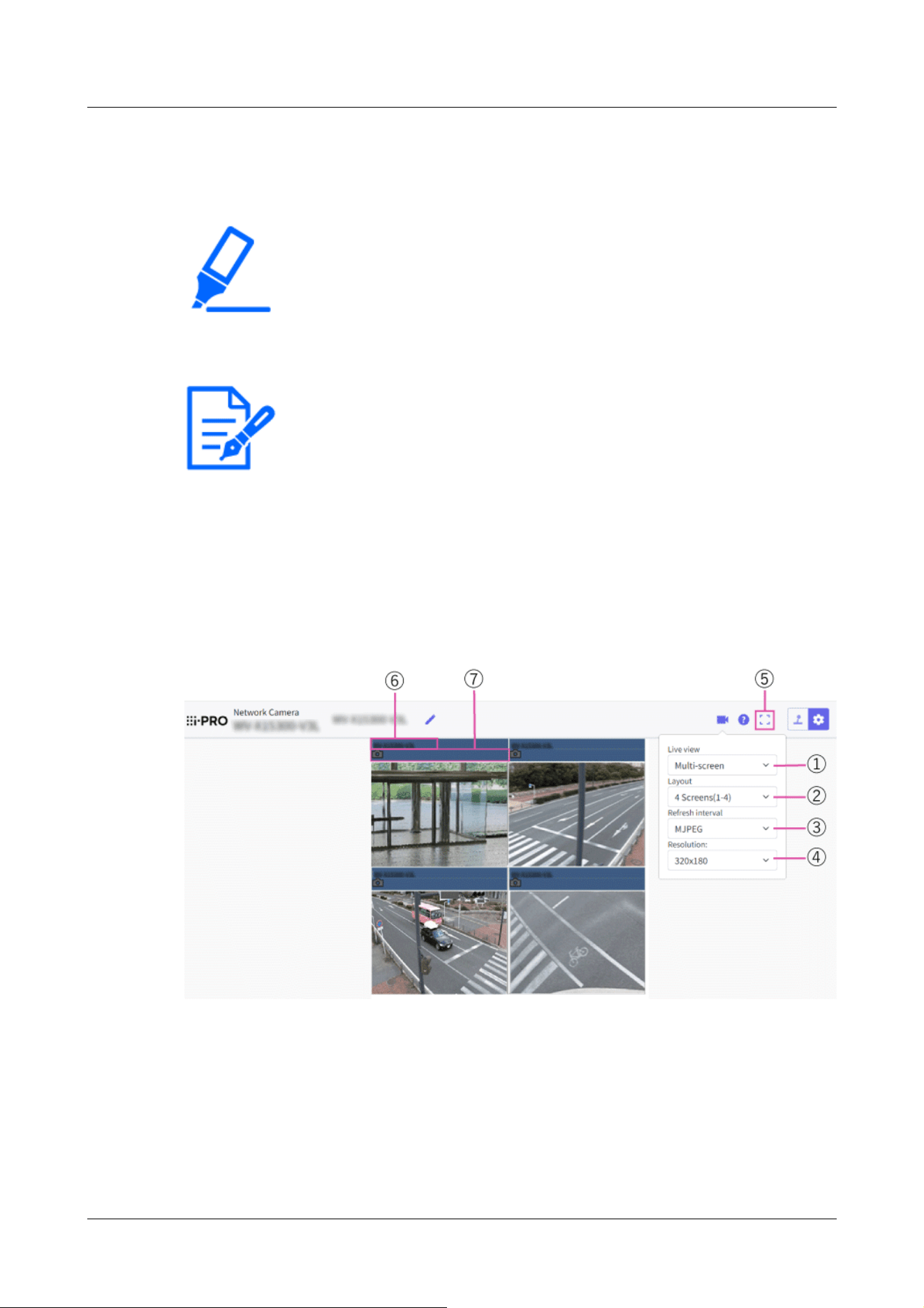
[Important]
・When 16 screens are used for the display, only still images (JPEG) can be refreshed.
・[New X Fixed-8MP][New X Fixed-6MP][New X Fixed-5MP][AI Outdoor IR
BulletX-8M][AI Outdoor IR BulletX-5M]This function is not available when
[Image capture mode] is set to [60fps Mode] or [50fps Mode].
[Note:]
・When you have registered a camera with the authentication function enabled, it is
necessary to access the camera and register the user name of “Administrator”
and password in the web browser in advance.
Refer to our technical information website <Control No.: C0302> for information
about the terms and conditions for use of multi-screen.
cameras) can be registered.
→13 Configure the multi-screen settings[Multi-screen]
From the [Live view] pull-down menu in the [Live] page, select [Multi-screen]. Images from the
registered cameras will be displayed on a selected multi-screen (screen can be splitup to 16
areas). The following are instructions when displaying on a 4-split screen.
① [Live view] pull-down menu
Select the image displayed in the main area.
② [Layout] pull-down menu
Select from the pull-down menu to display images from cameras in multi-screens of 4 to 9 or
even 16screens.
2 Operation
2.3 Viewing images from a PC
90

[Note:]
・The frame rate may drop depending on the network environment and number of
accessing users.
・If the image capture size specified for JPEG cannot be obtained, a JPEG image
with an image capture size that could be obtained is displayed. Therefore, when
JPEG images obtained with snapshot are displayed on a PC, the displayed image
size may differ from the captured sized.
③ [Refresh interval] pull-down menu
Select from the pull-down menu and switch between video (MJPEG) and still images
(JPEG).For still images (JPEG), select the refresh interval (Refresh interval : 1s/Refresh
interval : 3s/Refreshinterval : 5s/Refresh interval : 10s/Refresh interval : 30s/Refresh
interval : 60s) for camera images.
When the 16 screen layout is used, Refresh interval : 1s cannot be selected.
④ [Image capture size] pull-down menu
Select the image capture size from the pull-down menu to change it.When you select [4
Screens] in the [Layout] pull-down menu, the image capture size of the camerachanges.
⑤ Full screen display
If you press the full screen button, the display of the camera image will be maximized. If you
click the[x] button in the full screen display, the display size will be reset to original size.
⑥ Camera title
If you click the camera title, live images from the corresponding camera will be displayed on
the“Live” page of the newly opened window.
⑦ Camera control bar
Can be used to get snap shot of JPEG images.
2.4 Viewing images from mobile/tablet terminals
2.4.1 Viewing images from mobile devices (smartphones, etc.)
Connect a portable terminal to your computer and display images (MJPEG and JPEG formats) of
your computer. The latest image is automatically updated.
The following models are supported. As of April 2022
-iPad, iPhone (iOS 8 or later)
2 Operation
2.4 Viewing images from mobile/tablet terminals
91
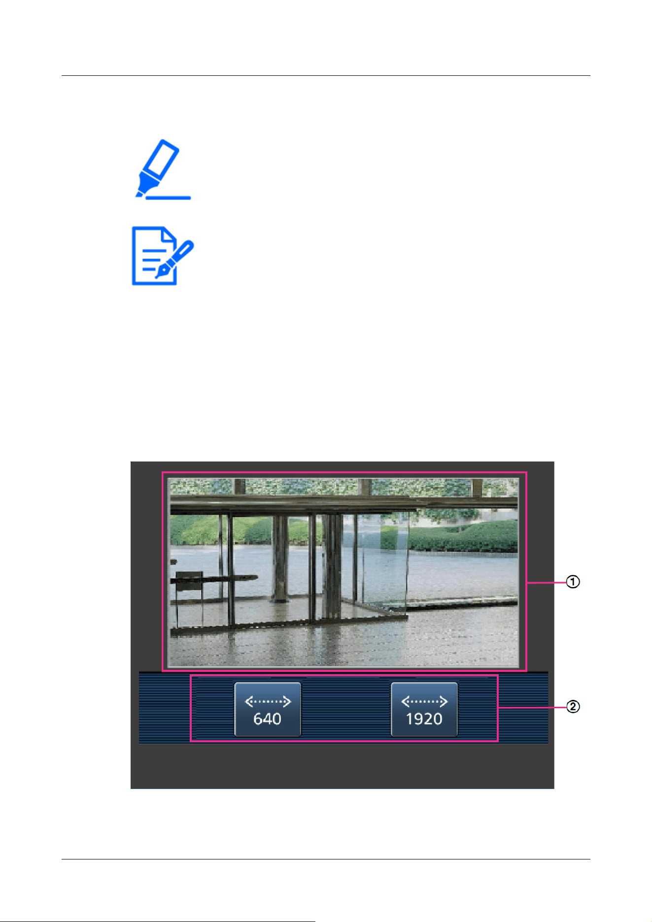
[Important]
・If the Authentication dialog appears, enter your username and password.
→15.1 [User auth.] to configure user-authentication
[Note:]
・In order to view images of your computer from a mobile terminal, it is necessary
to set up a network to connect to the Internet in advance.
→16 Networking configuration [Network]
・[New X Fixed-8MP][New X Fixed-6MP][New X Fixed-5MP][AI Outdoor IR
BulletX-8M][AI Outdoor IR BulletX-5M]Images cannot be displayed when [Image
capture mode] is set to [60fps Mode] or [50fps Mode].
-Android™ terminal
2.4.1.1 Viewing images of Fixed cameras from a portable terminal (smartphone, etc.)
1 [http://IP address/cam] by mobile phone
*1
Or [Host name/cam registered at http://DDNS
server]
*2
Enter and press the Enter button to view the this product image.
①[Live image]
2 Operation
2.4 Viewing images from mobile/tablet terminals
92
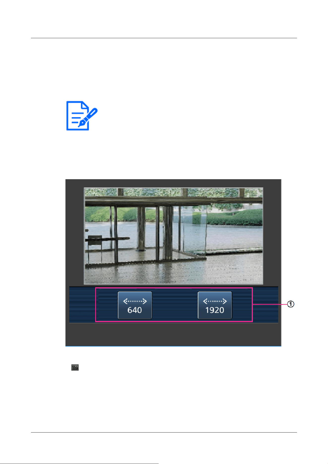
[Note:]
・The operation buttons displayed on the screen of the mobile terminal may not be
displayed depending on the user privileges and function permission settings of the
user to access. If you want to view the operations buttons, you need to set the
user privileges and function permissions ([User mng.] [User auth.]).
→15.1 [User auth.] to configure user-authentication
Displays the area camera image.
②[Operation button area]
When the function is selected in the function selection area, the button to operate the function
is displayed.
2 Click the button of the function you want to operate.
①[Image capture size switchover]
When the button is pressed, the button for selecting Image capture size is displayed.
Select Image capture size from the displayed buttons to toggle Image capture size.
The Image capture size set in the [JPEG(1)] [JPEG(2)] of the [JPEG] in the [Image] tab is
displayed.
2 Operation
2.4 Viewing images from mobile/tablet terminals
93

[Note:]
・Images with a Image capture size of "3840x2160", "3328x1872", "3072x2304",
"3072x1728", "2688x1520", "2560x1920", or "2560x1440" cannot be displayed.
[Note:]
・The screen size displayed on the mobile phone can be changed by accessing the
following.
-Large screen size: http://IP address/cam/dl
-Display medium: http://IP address/cam/dm
-display small: http://IP address/cam/ds
・The Image capture size displayed by performing [Resolution] changes, but the
size of the images does not change.
・If the HTTP port number is changed from 80, [http://IP address:port
number/cam]
*1
Enter the port number of the this product. If you are using the
DDNS function, [http://Host name registered on the DDNS server: Port
number/cam]
*2
Please enter.
・If you are configuring [HTTPS] in [HTTPS]-[Connection] on the [Advanced] tab
of the Network Page, enter the following.
Https://IP address: port number/cam or the host name registered with the
https://DDNS server: port number/cam
・When the Authentication dialog appears, enter the administrator's or general
user's username and password. Depending on the mobile phone, the password
may need to be entered each time the screen is switched.
・Audio cannot be received or sent from a mobile terminal.
・Some mobile terminals may not be able to display images when the image size is
large. This may be displayed when the [Image quality setting] of [JPEG] is close to
low quality.
→10.2 [Image] for setting JPEG images
*1 The IP address is the global IP address on the WAN side of the router that can be accessed
from the Internet.
However, it is the local IP address when accessing the this product in the same LAN with a
wireless connected mobile terminal.
*2 Only accesses this product via the Internet.
2 Operation
2.4 Viewing images from mobile/tablet terminals
94
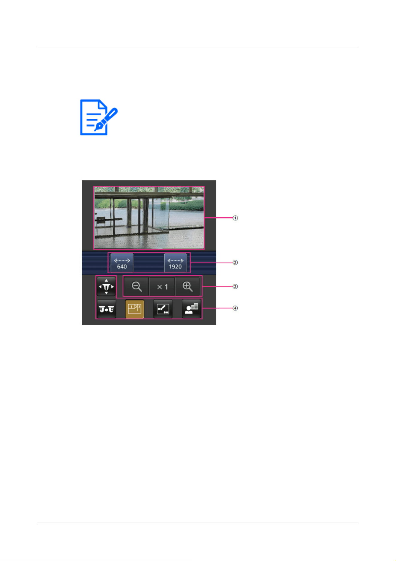
[Note:]
・The items that can be set differ depending on the function of the model.
・Refer to the catalog specifications for the functions installed in each model.
2.4.1.2 Viewing PTZ camera, AI Outdoor IR Bullet Camera images from a mobile terminal
(smartphone, etc.)
1 [http://IP address/cam] by mobile phone
*1
Or [Host name/cam registered at http://DDNS
server]
*2
Enter the data and press the Enter button to display the image of the computer.
①[Live image]
Displays the area camera image.
②[Operation button area]
When the function is selected in the function selection area, the button to operate the function
is displayed.
③[Zoom operation area]
Displays the zoom button.
④[Function selection area]
Displays and selects functions that can be operated, and the operation buttons are displayed in
the operation button area.
2 Operation
2.4 Viewing images from mobile/tablet terminals
95
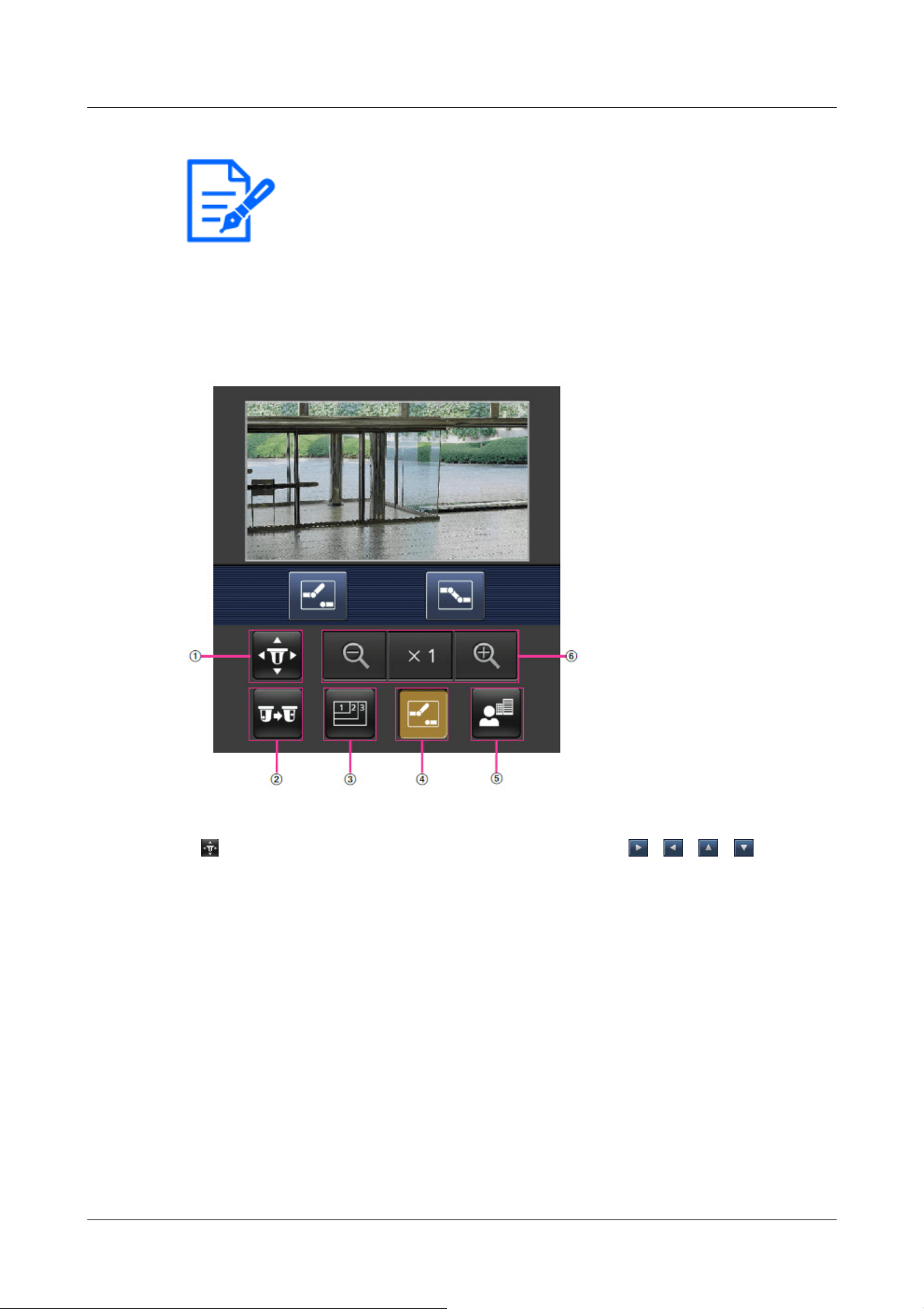
[Note:]
・The operation buttons displayed on the screen of the mobile terminal may not be
displayed depending on the user privileges and function permission settings of the
user to access. If you want to view the operations buttons, you need to set the
user privileges and function permissions ([User mng.] [User auth.]).
→15.1 [User auth.] to configure user-authentication
2 Click the button of the function you want to operate.
①[Pan/Tilt]
Press the button to display the button to operate the pan/tilt. 、 、 、 Press the
buttons to pan/tilt in each direction.
2 Operation
2.4 Viewing images from mobile/tablet terminals
96

②[Preset
Press the button to display the button for selecting the preset position. By selecting the
preset number from the displayed button, the camera image is displayed in the direction of the
preset registered camera.
Only position numbers 1 to 4 are displayed for preset positions.
Only registered preset positions are displayed, and unregistered preset positions are not
displayed.
③[Resolution switchover]
2 Operation
2.4 Viewing images from mobile/tablet terminals
97
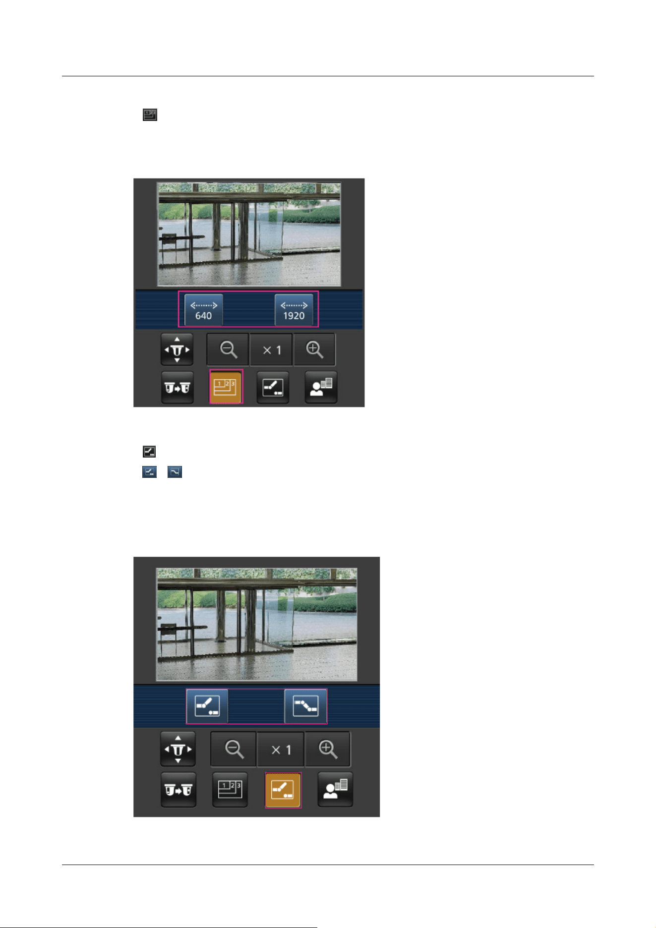
Press the button to display the screen for selecting the resolution.
The resolution is switched by selecting the resolution from the displayed buttons.
The resolution set in the [JPEG(1)] [JPEG(2)] of the [JPEG] in the [Image] tab is displayed.
④[Aux control]
Press the button to display the button to operate the AUX output.
、 The button enables you to control the AUX output terminal.
This message is displayed only when [Terminal 3] is set to [AUX output] in the operation
setting menu.
→14.1 [Alarm] to set alarm operation
2 Operation
2.4 Viewing images from mobile/tablet terminals
98

[Note:]
・The screen size displayed on the mobile phone can be changed by accessing the
following.
-Large screen size: http://IP address/cam/dl
-Display medium: http://IP address/cam/dm
⑤[Focus Display]
Press the button to display the button to perform the focus operation.
、 、 The button allows focusing of the camera image.
⑥[Zoom display]
、 、 You can zoom the camera image with the buttons.
2 Operation
2.4 Viewing images from mobile/tablet terminals
99

-display small: http://IP address/cam/ds
・The resolution displayed by [Resolution] changes, but the size of the images does
not change.
・If the HTTP port number is changed from 80, [http://IP address:port
number/cam]
*1
Enter the port number of the machine. If you are using the DDNS
function, [http://Host name registered on the DDNS server: Port number/cam]
*2
Please enter.
・If you are configuring [HTTPS] in [HTTPS]-[Connection] on the [Advanced] tab
of the Network Page, enter the following.
Https://IP address: port number/cam or the host name registered with the
https://DDNS server: port number/cam
・When the Authentication dialog appears, enter the administrator's or general
user's username and password. Depending on the mobile phone, the password
may need to be entered each time the screen is switched.
・Audio cannot be received or sent from a mobile terminal.
・Some mobile terminals may not be able to display images when the image size is
large. This may be displayed when the [Image quality setting] of [JPEG] is close to
low quality.
→10.2 [Image] for setting JPEG images
*1 The IP address is the global IP address on the WAN side of the router that can be accessed
from the Internet.
Note, however, that this is the local IP address when accessing the handset in the same LAN
with a mobile terminal supporting wireless connection.
*2 Only for accessing the computer via the Internet.
2.4.1.3 Viewing images of a Multi-directional camera from a portable terminal (smartphone,
etc.)
1 [http://IP address/cam] by mobile phone
*1
Or [Host name/cam registered at http://DDNS
server]
*2
Enter the data and press the Enter button to display the image of the computer.
2 Operation
2.4 Viewing images from mobile/tablet terminals
100
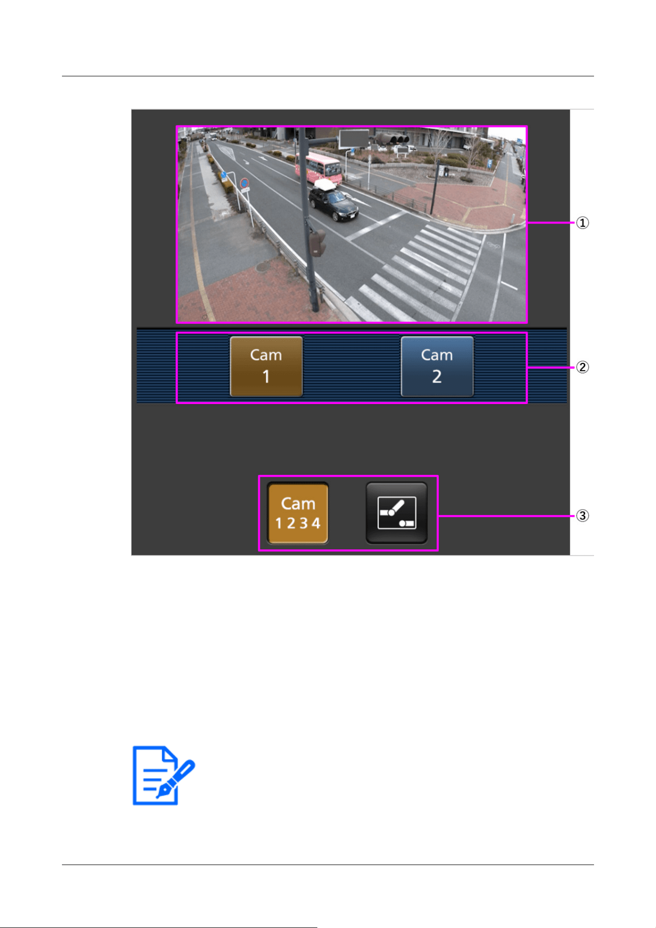
[Note:]
・The operation buttons displayed on the screen of the mobile terminal may not be
displayed depending on the user privileges and function permission settings of the
user to access. If you want to view the operations buttons, you need to set the
①[Live image]
Displays the area camera image.
②[Operation button area]
When the function is selected in the function selection area, the button to operate the function
is displayed.
③[Function selection area]
Displays and selects functions that can be operated, and the operation buttons are displayed in
the operation button area.
2 Operation
2.4 Viewing images from mobile/tablet terminals
101
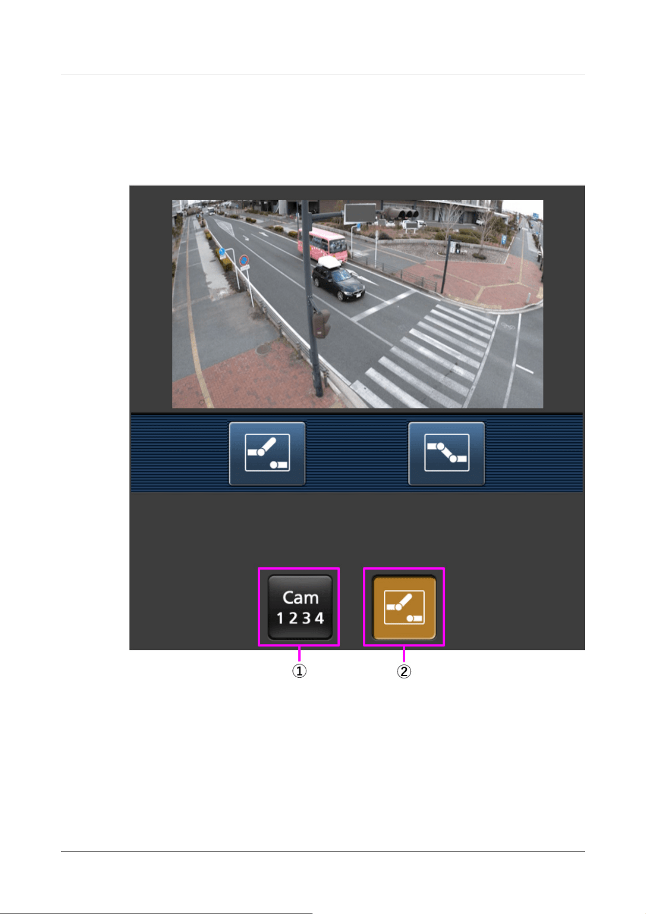
user privileges and function permissions ([User mng.] [User auth.]).
→15.1 [User auth.] to configure user-authentication
2 Click the button of the function you want to operate.
①[Camera switchover]
When the button is pressed, the button to select the camera is displayed on the screen.
Select the camera from the displayed button to change the displayed camera.
Images of Cameras 1 and 2 are displayed in the Image capture size set in [JPEG] in the [Image]
tab.
2 Operation
2.4 Viewing images from mobile/tablet terminals
102
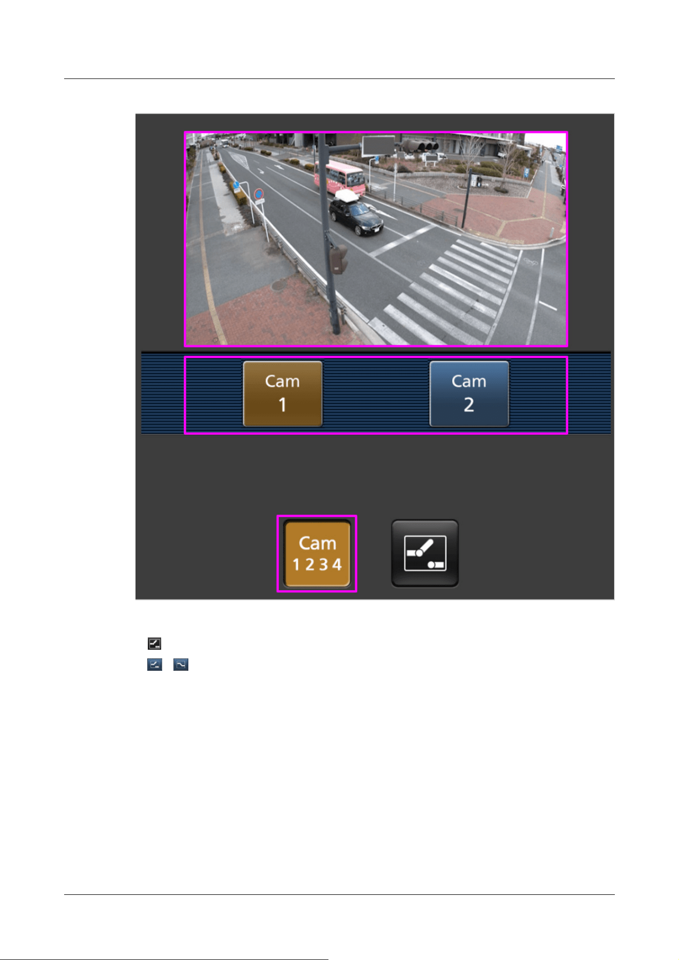
②[Aux control]
Press the button to display the button to operate the AUX output.
、 The button enables you to control the AUX output terminal.
This message is displayed only when [Terminal 3] is set to [AUX output] in the operation
setting menu.
→14.1 [Alarm] to set alarm operation
2 Operation
2.4 Viewing images from mobile/tablet terminals
103
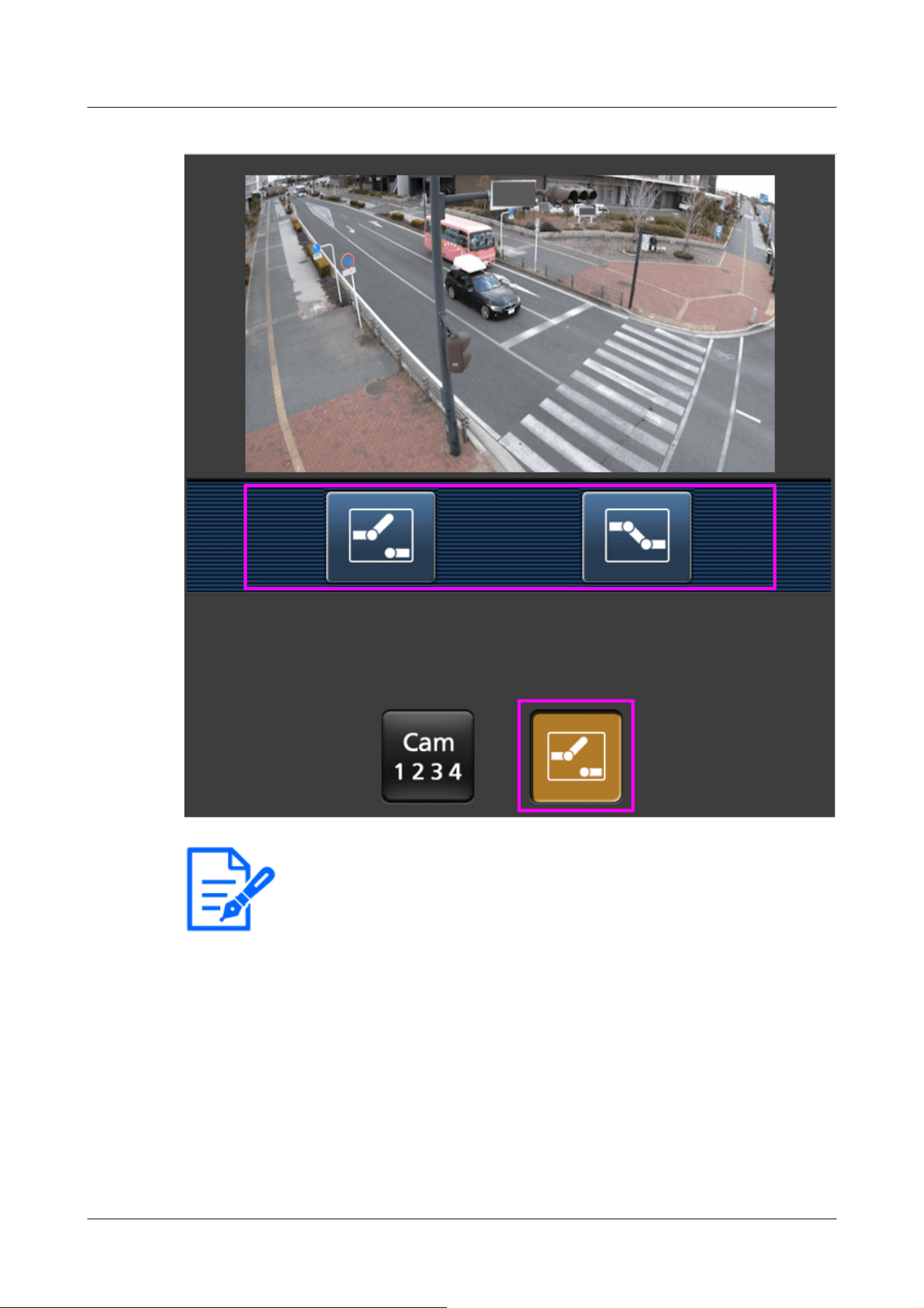
[Note:]
・If the HTTP port number is changed from 80, [http://IP address:port
number/cam]
*1
Enter the port number of the machine. If you are using the DDNS
function, [http://Host name registered on the DDNS server: Port number/cam]
*2
Please enter.
・If you are configuring [HTTPS] in [HTTPS]-[Connection] on the [Advanced] tab
of the Network Page, enter the following.
Https://IP address: port number/cam or the host name registered with the
https://DDNS server: port number/cam
・When the Authentication dialog appears, enter the administrator's or general
user's username and password. Depending on the mobile phone, the password
2 Operation
2.4 Viewing images from mobile/tablet terminals
104
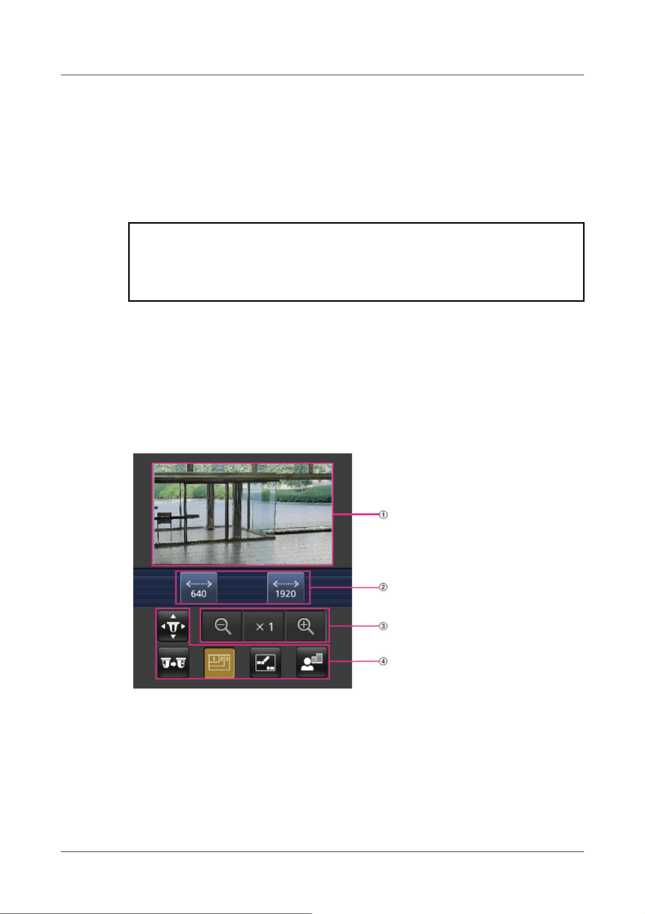
may need to be entered each time the screen is switched.
・Audio cannot be received from a portable terminal.
・Some mobile terminals may not be able to display images when the image size is
large. This may be displayed when the [Image quality setting] of [JPEG] is close to
low quality.
*1 The IP address is the global IP address on the WAN side of the router that can be accessed
from the Internet. Note, however, that this is the local IP address when accessing the handset
in the same LAN with a mobile terminal supporting wireless connection.
*2 Only for accessing the computer via the Internet.
2.4.1.4 Viewing images of a Multi-directional/PTZ camera from a portable terminal
(smartphone, etc.)
PTZ camera
1 [http://IP address/cam] by mobile phone
*1
Or [Host name/cam registered at http://DDNS
server]
*2
Enter the data and press the Enter button to display the image of the computer.
①[Live image]
Displays the area camera image.
②[Operation button area]
When the function is selected in the function selection area, the button to operate the function
is displayed.
2 Operation
2.4 Viewing images from mobile/tablet terminals
105
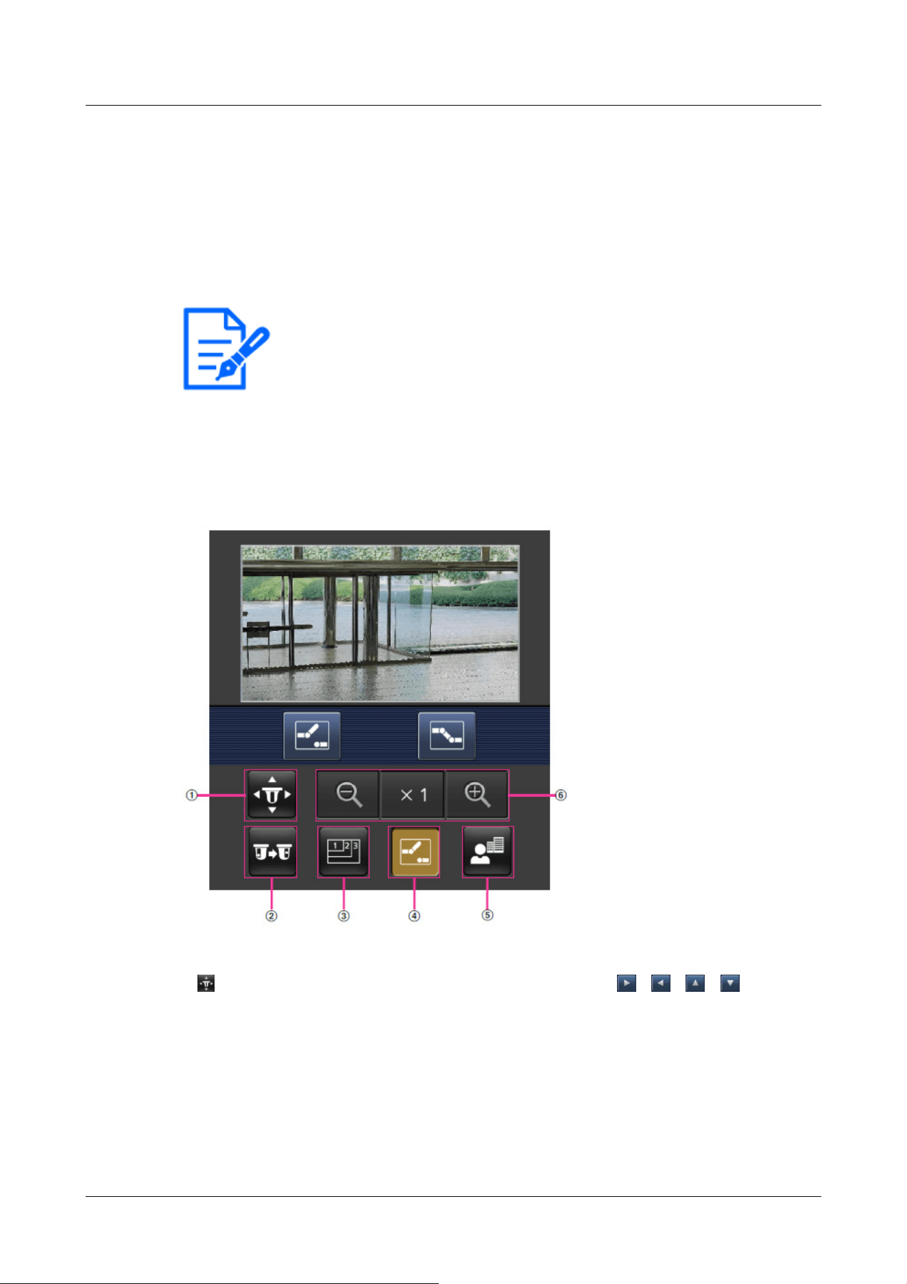
[Note:]
・The operation buttons displayed on the screen of the mobile terminal may not be
displayed depending on the user privileges and function permission settings of the
user to access. If you want to view the operations buttons, you need to set the
user privileges and function permissions ([User mng.] [User auth.]).
→15.1 [User auth.] to configure user-authentication
③[Zoom operation area]
Displays the zoom button.
④[Function selection area]
Displays and selects functions that can be operated, and the operation buttons are displayed in
the operation button area.
2 Click the button of the function you want to operate.
①[Pan/Tilt]
Press the button to display the button to operate the pan/tilt. 、 、 、 Press the
buttons to pan/tilt in each direction.
2 Operation
2.4 Viewing images from mobile/tablet terminals
106
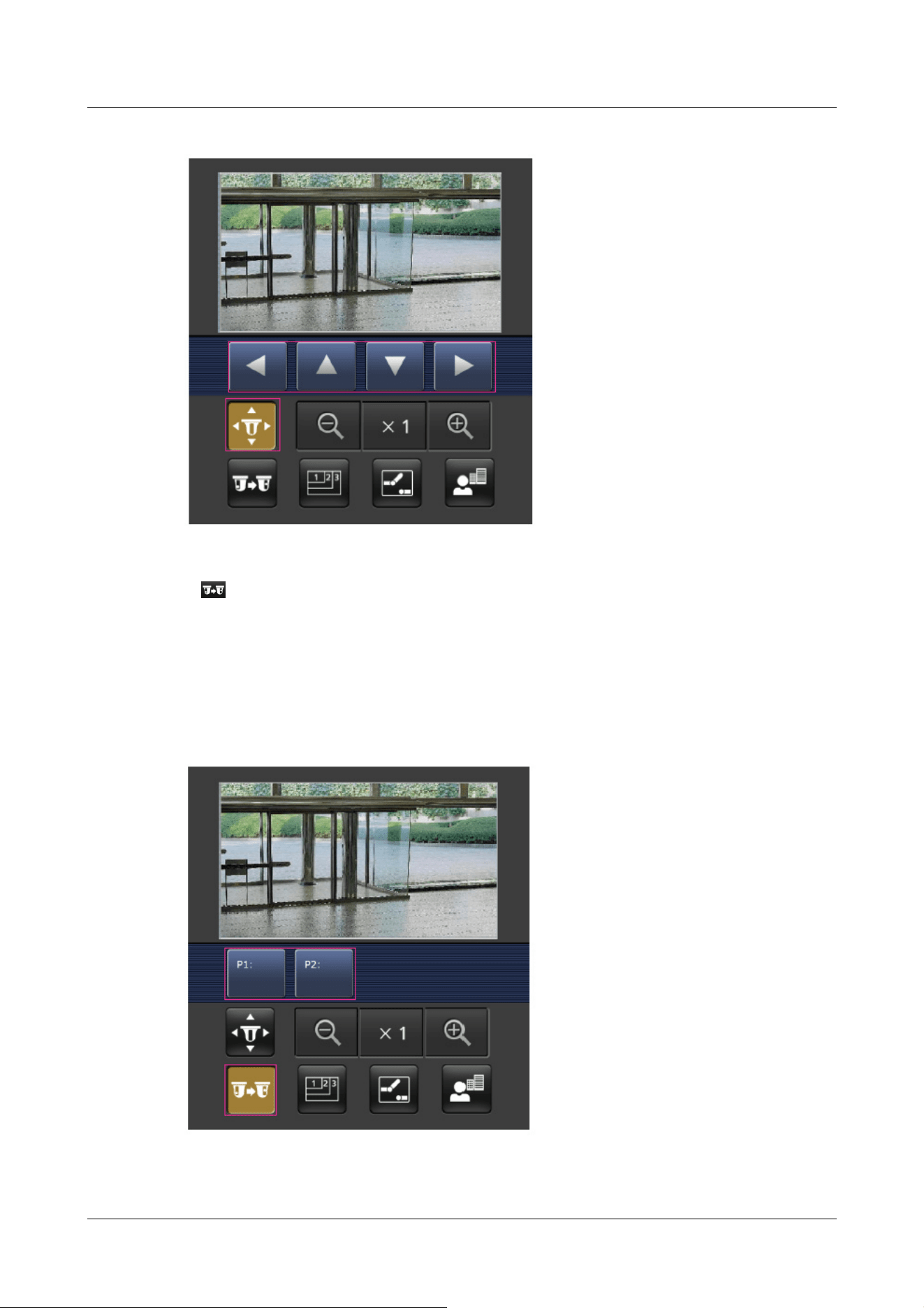
②[Preset]
Press the button to display the button for selecting the preset position. By selecting the
preset number from the displayed button, the camera image is displayed in the direction of the
preset registered camera.
Only position numbers 1 to 4 are displayed for preset positions.
Only registered preset positions are displayed, and unregistered preset positions are not
displayed.
③[Resolution switchover]
2 Operation
2.4 Viewing images from mobile/tablet terminals
107

Press the button to display the screen for selecting the resolution.
The resolution is switched by selecting the resolution from the displayed buttons.
The resolution set in the [JPEG(1)] [JPEG(2)] of the [JPEG] in the [Image] tab is displayed.
④[Aux control]
Press the button to display the button to operate the AUX output.
、 The button enables you to control the AUX output terminal.
This message is displayed only when [Terminal 3] is set to [AUX output] in the operation
setting menu.
→14.1 [Alarm] to set alarm operation
2 Operation
2.4 Viewing images from mobile/tablet terminals
108
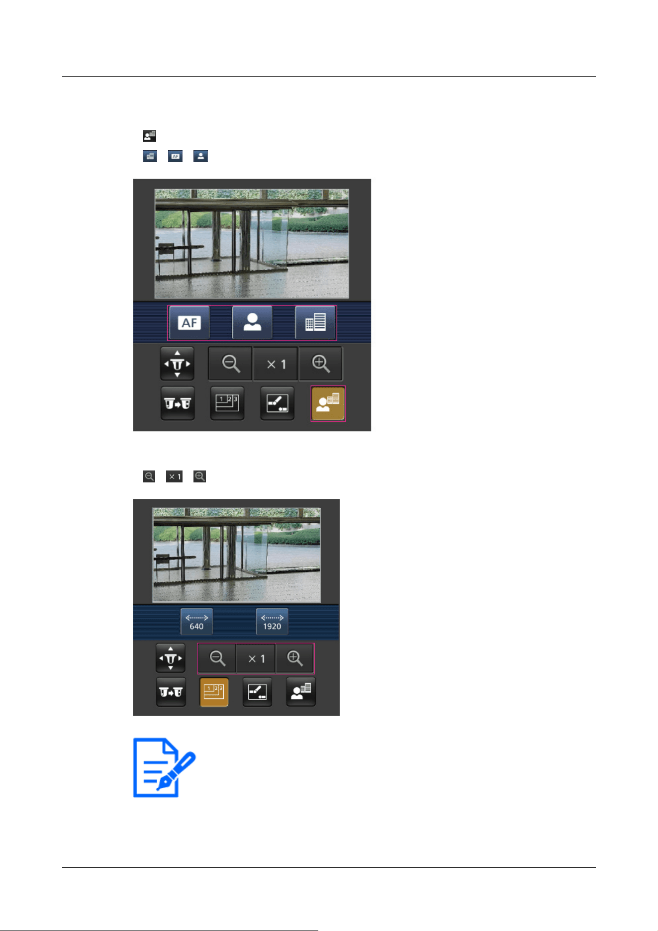
[Note:]
・The screen size displayed on the mobile phone can be changed by accessing the
following.
-Large screen size: http://IP address/cam/dl
-Display medium: http://IP address/cam/dm
⑤[Focus Display]
Press the button to display the button to perform the focus operation.
、 、 The button allows focusing of the camera image.
⑥[Zoom display]
、 、 You can zoom the camera image with the buttons.
2 Operation
2.4 Viewing images from mobile/tablet terminals
109

-display small: http://IP address/cam/ds
・The resolution displayed by [Resolution] changes, but the size of the images does
not change.
・If the HTTP port number is changed from 80, [http://IP address:port
number/cam]
*1
Enter the port number of the machine. If you are using the DDNS
function, [http://Host name registered on the DDNS server: Port number/cam]
*2
Please enter.
・If you are configuring [HTTPS] in [HTTPS]-[Connection] on the [Advanced] tab
of the Network Page, enter the following.
Https://IP address: port number/cam or the host name registered with the
https://DDNS server: port number/cam
・When the Authentication dialog appears, enter the administrator's or general
user's username and password. Depending on the mobile phone, the password
may need to be entered each time the screen is switched.
・Audio cannot be received or sent from a mobile terminal.
・Some mobile terminals may not be able to display images when the image size is
large. This may be displayed when the [Image quality setting] of [JPEG] is close to
low quality.
→10.2 [Image] for setting JPEG images
*1 The IP address is the global IP address on the WAN side of the router that can be accessed
from the Internet.
Note, however, that this is the local IP address when accessing the handset in the same LAN
with a mobile terminal supporting wireless connection.
*2 Only for accessing the computer via the Internet.
Multi-directional camera
1 [http://IP address/cam] by mobile phone
*1
Or [Host name/cam registered at http://DDNS
server]
*2
Enter the data and press the Enter button to display the image of the computer.
2 Operation
2.4 Viewing images from mobile/tablet terminals
110
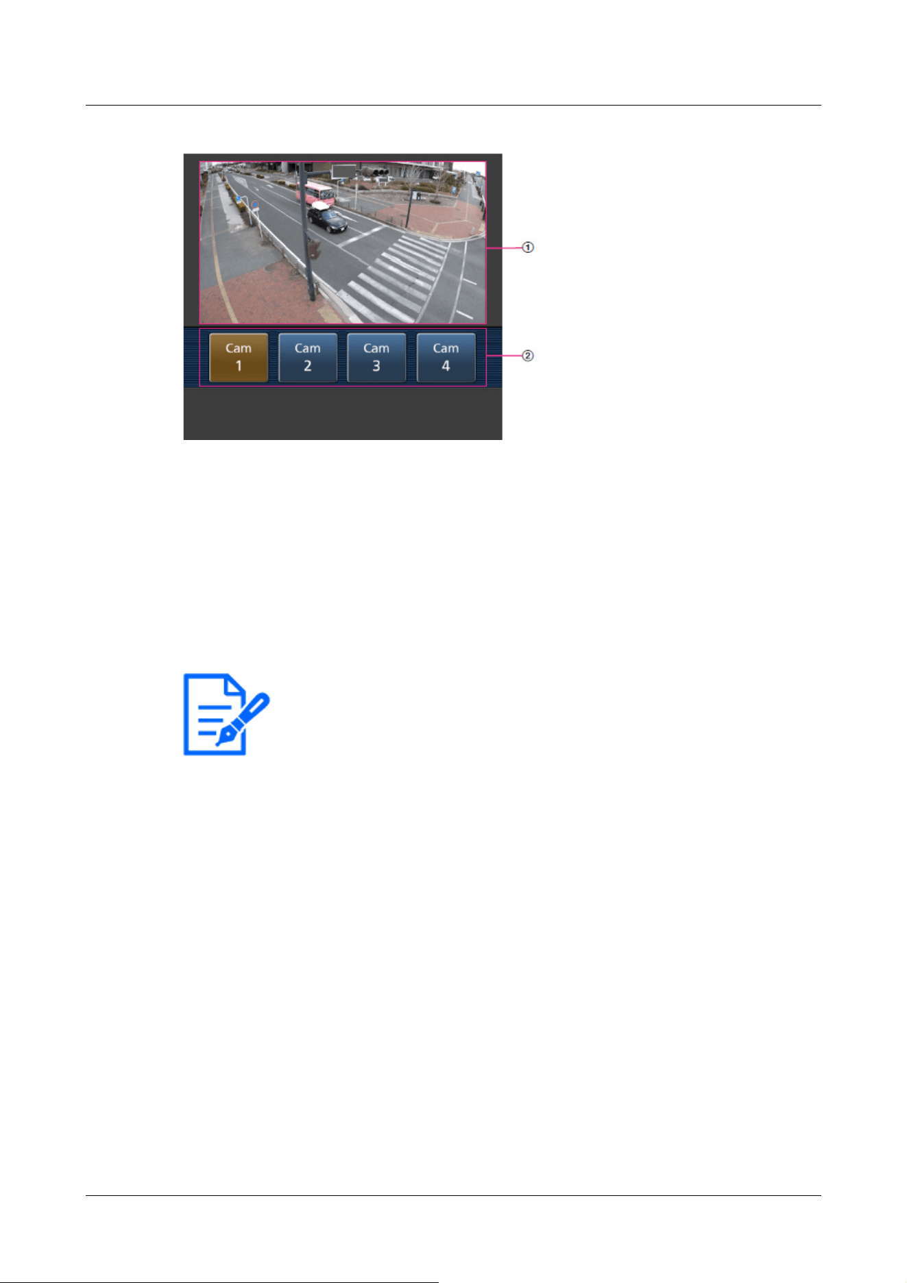
[Note:]
・The operation buttons displayed on the screen of the mobile terminal may not be
displayed depending on the user privileges and function permission settings of the
user to access. If you want to view the operations buttons, you need to set the
user privileges and function permissions ([User mng.] [User auth.]).
→15.1 [User auth.] to configure user-authentication
・If the HTTP port number is changed from 80, [http://IP address:port
number/cam]
*1
Enter the port number of the machine. If you are using the DDNS
function, [http://Host name registered on the DDNS server: Port number/cam]
*2
Please enter.
・If you are configuring [HTTPS] in [HTTPS]-[Connection] on the [Advanced] tab
of the Network Page, enter the following.
Https://IP address: port number/cam or the host name registered with the
https://DDNS server: port number/cam
・When the Authentication dialog appears, enter the administrator's or general
user's username and password. Depending on the mobile phone, the password
may need to be entered each time the screen is switched.
①[Live image]
Displays the area camera image.
②[Camera switchingArea]
The button for selecting the camera to be displayed in the live image is displayed.
Select the camera from the displayed button to change the displayed camera.
Images of cameras 1, 2, 3 and 4 are displayed at the resolution set in [JPEG] in the [Image]
tabs.
2 Operation
2.4 Viewing images from mobile/tablet terminals
111

・Some mobile terminals may not be able to display images when the image size is
large. This may be displayed when the [Image quality setting] of [JPEG] is close to
low quality.
*1 The IP address is the global IP address on the WAN side of the router that can be accessed
from the Internet. Note, however, that this is the local IP address when accessing the handset
in the same LAN with a mobile terminal supporting wireless connection.
*2 Only for accessing the computer via the Internet.
[Important]
・If the Authentication dialog appears, enter your username and password.
→15.1 [User auth.] to configure user-authentication
[Note:]
・To view images on your computer from a tablet terminal, it is necessary to set up
a network to connect to the Internet in advance.
→16 Networking configuration [Network]
・Depending on the model, the same screen as the PC may be displayed. In this
case, enter either [http://IP address/live/tab.html] or [http://DDNS
server/live/tab.html] to connect.
・[New X Fixed-8M][New X Fixed-6M][New X Fixed-5M][AI Outdoor IR
BulletX-8M][AI Outdoor IR BulletX-5M]Images cannot be displayed when [Image
capture mode] is set to [60fps Mode] or [50fps Mode].
2.4.2 View images from a tablet terminal
Connect the tablet terminal to the computer and display images (MJPEG and JPEG formats) of the
computer. The latest image is automatically updated. The following models are supported. As of
April 2022
-iPad, iPhone (iOS 8 or later)
-Android terminal
2 Operation
2.4 Viewing images from mobile/tablet terminals
112
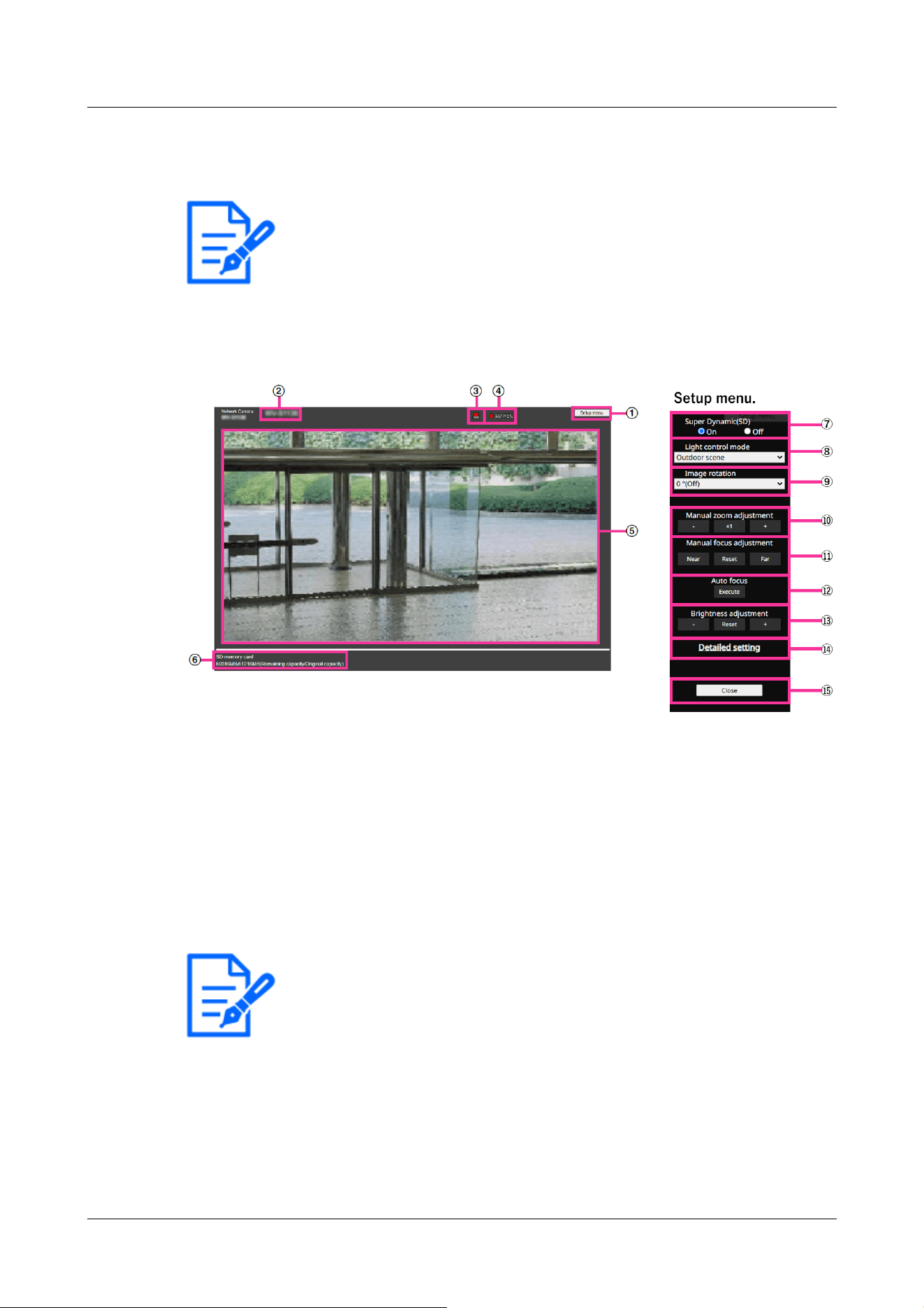
[Note:]
・The items that can be set differ depending on the function of the model.
・Refer to the catalog specifications for the functions installed in each model.
[Note:]
・The alarm notification button blinks in conjunction with the alarm notification
operation such as mail transfer. Check the operation setting.
2.4.2.1 Viewing images of Fixed cameras from a tablet terminal
1 [http://IP address] on the tablet terminal
*1
Or [host name/ registered in the http://DDNS
server]
*2
When typing and connecting to this product, the this product images are displayed.
①[Setup menu.] buttons*3
Indicates the setup menu.
②[Camera title]
The title of the camera entered in [Camera title] on the [Basic] tab is displayed.
→3.2 [Basic] to perform basic settings
③[Alarm Notification button]*4
The lamp blinks when an alarm is generated. Click the button to disappear.
④[SD Storage Status Display]
Displays the storage status on the SD Memory Card. When saving starts, the SD save status
indicator turns red. The LED turns OFF when saving stops.
This is displayed when the [Save trigger] in the Setup menu is set to [Manual save] or [Schedule].
2 Operation
2.4 Viewing images from mobile/tablet terminals
113

[Note:]
・Set [Super Dynamic] to [Off] when the following phenomena are observed
depending on the lighting condition.
-when flickering or color changes occur
-when noise is generated in the bright area of the screen
・When [Stabilizer] is set to [On], the superdynamic setting is [Off].
[Note:]
・When [Image capture mode] is 25fps, [Indoor scene(60Hz)] cannot be set.
→9.2 [SD memory card] for setting SD Memory Cards
⑤[Main area]
Live displays the camera image.
⑥[Capacity display]
The remaining capacity and total capacity of the SD Memory Card are displayed.
⑦[Super dynamic setting]
You can set [On] or [Off] to activate the super dynamic function. You can set for each preset
position. This cannot be set when [Image capture mode] is in [60 fps mode] or [50 fps mode].
See [What is Super Dynamic] for details on super dynamic.
[On]:The Super Dynamic function is activated.
[Off]:Stops the superdynamic function.
⑧[Light control mode] pull-down menu
Select the mode to control the light intensity from the following.
[Flickless (50 Hz)]/[Flickless (60 Hz)]:Flicker is automatically corrected with a fluorescent
lamp. 50 Hz/60 Hz will be used differently in different regions.
[ELC]:The electronic shutter is used to control the light intensity.
⑨[Image Rotation]
Set whether to rotate the image (JPEG, H.265 or H.264).
0°(Off):The image is not rotated.
90°:Rotate the image 90 degrees.
180 degrees (vertical inversion):The image is inverted up and down.
270°:Rotate the image 270 degrees.
2 Operation
2.4 Viewing images from mobile/tablet terminals
114

[Important]
・If the image rotation setting is changed with the following area set, the position
will be misaligned. Therefore, set each area after setting image rotation.
-Privacy zone
-VMD area
-SCD area
-VIQS area
-Mask area
-overlay image
-Focus frame
・If you set [Image Rotation] to [90°] or [270°], the character on the screen may
be broken depending on the [Character Size] setting and the number of characters.
・When [Rotate images] is set to [90°] and [270°], the positions that can be set
to [Date/time position] and [Camera title position] are limited to [upper left] and
[lower left].
[Note:]
・If [Image capture size] is 320 x 180, [Image rotation] cannot be set to 90° or
270°.
・[New X Fixed][AI Outdoor IR BulletX]Even when [Image capture size] is set to
320x180, you can set [Image rotation] to 90° or 270°.
[Note:]
・The zoom (magnification) switches between the optical zoom and EX optical
zoom.
[Important]
・With the Mask area, Privacy zone, VMD area, SCD area, and VIQS area set,
setting the EX optical zoom will shift the position. Therefore, set the EX optical
zoom and then set each area.
.
.
⑩[Manual zoom adjustment]
Adjust the zoom manually.
[-]: Adjust the zoom factor to 1.0 times in the [Wide angle] direction.
[x1]: Zoom (magnification) is 1.0 times.
[+]: Adjust the zoom factor in the [Telephone] direction.
2 Operation
2.4 Viewing images from mobile/tablet terminals
115

→10.4.2 Set the mask area
→10.4.6 Setting the privacy zone (Privacy zone setting screen)
→14.6 [VMD area] to set the motion detection area
→14.8 [SCD area] to set up SCD area
→10.4.8 Set up the VIQS area
[Note:]
・One-click on the [Near] or [Far] buttons may appear to have no change in focus
due to trace adjustments. If you want to move the focus position large, press and
hold the button for a long time.
[Important]
・If auto focus is executed while the slow shutter is running (e.g. at night) with the
[Maximum shutter] set to a longer time than [1/30s maximum] (2/30s maximum],
[4/30s maximum], [6/30s maximum], [10/30s maximum], or [16/30s maximum]),
it may take a lot of time to complete auto focus.
・The focus may not be adjusted automatically in the following locations or subject.
In this case, adjust the focus manually.
-Be a big move
-Large variation in illumination
-Low illumination-Extremely bright or reflected light
-Over the window
-where the dome cover is prone to contamination
-White walls are less dark.
-Flicker fiercely
・When the image is switched from color to black and white in the near infrared
region, the focus may shift due to the optical characteristics. If [Focusing at Day
⑪[Manual focus adjustment]
Adjust the focus manually.
[Near]: Adjust the focus to the [Near].
[Reset] returns focus (focus) to its default settings.
[Far]: Adjust the focus to the [Far].
⑫[Auto focus]
When [Execute] is clicked, the auto focus function is activated to automatically adjust the focus
to the subject in the center of the picture.
2 Operation
2.4 Viewing images from mobile/tablet terminals
116

& Night switching] is set to [Auto] or [Preset], the camera can focus automatically
(it does not support the lighting change after the focus operation is completed).
[Note:]
・When accessing the advanced settings screen on a tablet device, some
operations are not available, such as long-pressing zoom and focus does not work
or the slide bar cannot be moved.
[Note:]
・If the HTTP port number is changed from 80, [http://IP address:port number/]
*1
Enter the port number of the this product. If the DDNS function is used,
[http://Host name registered on the DDNS server: Port number/]
*3
Please enter.
・If you are configuring [HTTPS] in [HTTPS]-[Connection] on the [Advanced] tab
of the Network Page, enter the following.
[https://IP address:port number/] or [host name registered on the https://
DDNS server: port number/]
・When the Authentication dialog appears, enter the administrator's or general
user's username and password. Depending on the mobile phone, the password
may need to be entered each time the screen is switched.
・Depending on the tablet terminal, the image may not be displayed when the size o
f
the image is large. This may be displayed when the [Image quality setting] of
[JPEG] is close to low quality.
→10.2 [Image] for setting JPEG images
・You may not be able to access some tablets and contract plans.
⑬[Brightness adjustment] buttons
Adjust the brightness.
Press the [Light (+)] button to brighten the image.
Press the [Dark (-)] button to darken the image.
Press [Reset] to return to the default brightness.
⑭[Detailed setting] button
The Detailed setting screen is displayed in a new tab.
→5.3 Camera Advanced Menu Screen
⑮[Close] buttons
Hides the Setup menu.
2 Operation
2.4 Viewing images from mobile/tablet terminals
117
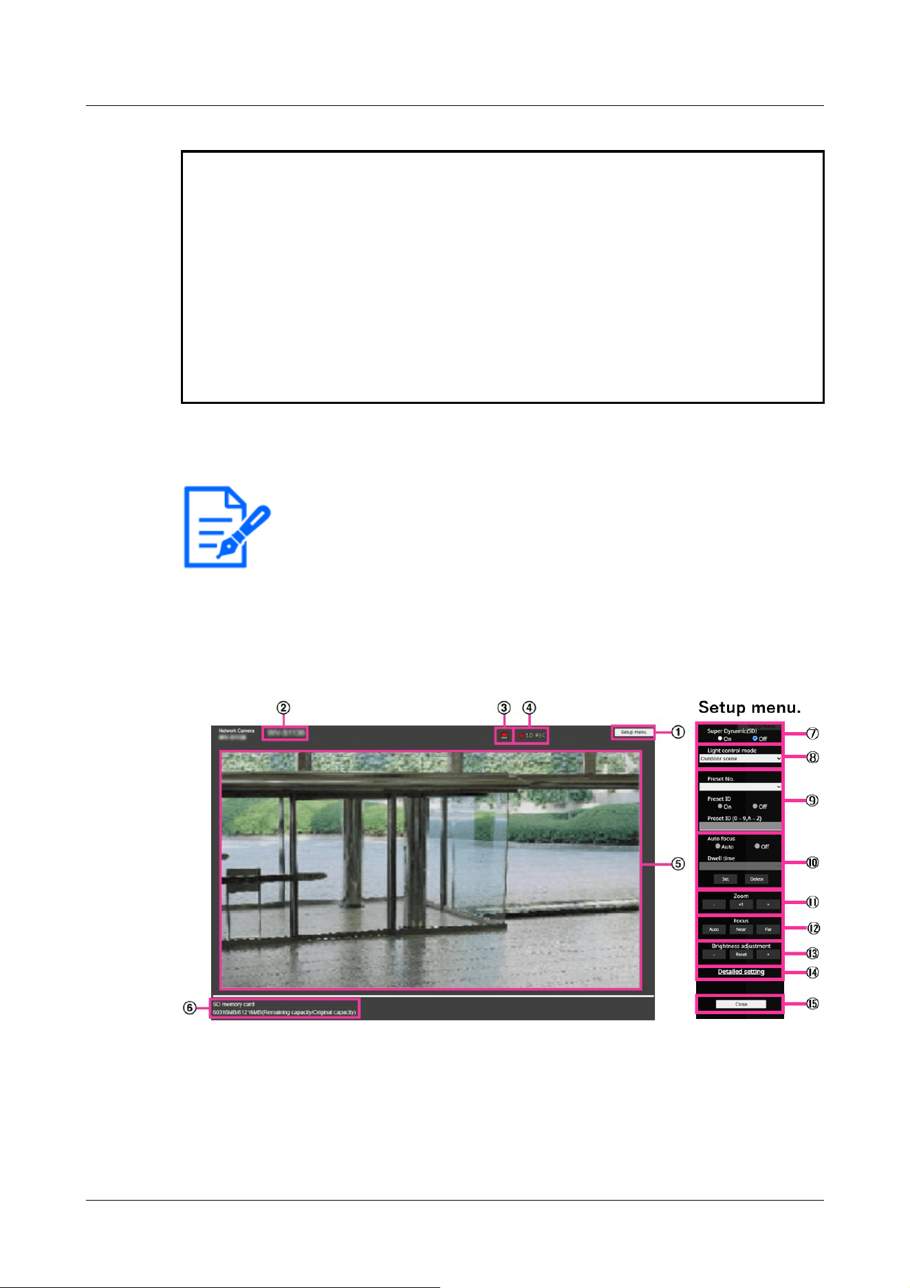
*1 The IP address is the global IP address on the WAN side of the router that can be accessed
from the Internet.
However, it is the local IP address when accessing the this product in the same LAN with a
wireless connected mobile terminal.
*2 Only accesses this product via the Internet.
*3 It is available only for users whose access levels are set to [1. Administrator].
*4 When [User auth.] is set to [On], only users with access levels set to [1. Administrator] or [2.
Camera control] can work.
→15.1 [User auth.] to configure user-authentication
[Note:]
・The items that can be set differ depending on the function of the model.
・Refer to the catalog specifications for the functions installed in each model.
2.4.2.2 View PTZ camera images from a tablet terminal
1 [http://IP address] on the tablet terminal
*1
Or [host name/ registered in the http://DDNS
server]
*2
The image of the computer is displayed when you enter it and connect it to the
computer.
①[Setup menu.] buttons*3
Indicates the setup menu.
②[Camera title]
The title of the camera entered in [Camera title] on the [Basic] tab is displayed.
2 Operation
2.4 Viewing images from mobile/tablet terminals
118

[Note:]
・The alarm notification button blinks in conjunction with the alarm notification
operation such as mail transfer. Check the operation setting.
[Note:]
・Set [Super Dynamic] to [Off] when the following phenomena are observed
depending on the lighting condition.
-when flickering or color changes occur
-when noise is generated in the bright area of the screen
・If [Light control mode] is set to [Fix shutter], [Super Dynamic] cannot be set to
[On].
・When [Stabilizer] is set to [On], the superdynamic setting is [Off].
→3.2 [Basic] to perform basic settings
③[Alarm Notification button]*4
The lamp blinks when an alarm is generated. Click the button to disappear.
④[SD Storage Status Display]
Displays the storage status on the SD Memory Card. When saving starts, the SD save status
indicator turns red. The LED turns OFF when saving stops.
This is displayed when the [Save trigger] in the Setup menu is set to [Manual] or [Schedule].
→9.2 [SD memory card] for setting SD Memory Cards
⑤[Main area]
Live displays the camera image.
⑥[Capacity display]
The remaining capacity and total capacity of the SD Memory Card are displayed.
⑦[Super dynamic setting]
You can set [On] or [Off] to activate the super dynamic function. You can set for each preset
position. This cannot be set when [Image capture mode] is in [60 fps mode] or [50 fps mode].
See [What is Super Dynamic] for details on super dynamic.
[On]:The Super Dynamic function is activated.
[Off]:Stops the superdynamic function.
⑧[Light control mode] pull-down menu
Select the mode to control the light intensity from the following.
[Outdoor shooting]:The brightness (illumination) controls the light intensity by combining the
electronic shutter and automatic aperture. This setting is used when shooting bright subjects
2 Operation
2.4 Viewing images from mobile/tablet terminals
119

[Note:]
・If you increase the shutter speed (~1/10,000), you will be less prone to blur
even when the subject moves faster.
・Increasing the shutter speed decreases the sensitivity.
・If [Super Dynamic] is set to [On], [Fix shutter] cannot be set. To configure [Fix
shutter], set [Super Dynamic] to [Off].
・[Indoor scene(60Hz)] cannot be set when [Image capture mode] is in 25fps, 50fps,
or 12.5fps modes.
such as outdoors. Be careful not to flicker under fluorescent lights, etc.
[Flickless (50 Hz)]/[Flickless (60 Hz)]:Flicker is automatically corrected with a fluorescent
lamp. 50 Hz/60 Hz will be used differently in different regions.
[Fixed shutter]:
If [Image capture mode] is in 30 fps or 15 fps mode:
[1/30 fixed], [3/120 fixed], [2/100 fixed], [2/120 fixed], [1/100 fixed], [1/120 fixed], [1/250
fixed], [1/500 fixed], [1/1000 fixed], [1/2000 fixed], [1/4000 fixed], or [1/10000 fixed]
If [Image capture mode] is in 25 fps or 12.5 fps mode:
[1/25 fixed]/[3/100 fixed]/[2/100 fixed]/[1/100 fixed]/[1/250 fixed]/[1/500 fixed]/[1/1000
fixed]/[1/2000 fixed]/[1/4000 fixed]/[1/10000 fixed]
When [Image capture mode] is 60 fps:
[1/60 fixed]/[1/100 fixed]/[1/120 fixed]/[1/250 fixed]/[1/500 fixed]/[1/1000 fixed]/[1/2000
fixed]/[1/4000 fixed]/[1/10000 fixed]
If [Image capture mode] is in 50fps mode:
[1/50 fixed]/[1/100 fixed]/[1/250 fixed]/[1/500 fixed]/[1/1000 fixed]/[1/2000 fixed]/[1/4000
fixed]/[1/10000 fixed]
⑨[Preset position setting]
Set the preset position.
Before registering the preset, move the camera in the direction you want to register.
To change the orientation of the camera, enable [Swipe operation permission] and select the
image position to be centered on the image angle. The camera's orientation moves to a position
centered on the clicked position.
If you want to zoom in, enable [Swipe operation permission] and select the zoom area in the
picture.
2 Operation
2.4 Viewing images from mobile/tablet terminals
120

[Important]
・When registering a preset position using a tablet, pay attention to the following.
-If updating of the image on the tablet is slow, it is recommended that you register
the preset while viewing the image on the confirmation monitor.
-If you resize the screen with tablet operation, you may not be able to change the
orientation or zoom in on the screen.
-If the orientation of the camera cannot be adjusted by tablet operation, refer to
the following to move the camera orientation in the direction you want to register.
→2.4.1 Viewing images from mobile devices (smartphones, etc.)
[Important]
・If you set [Preset ID], be sure to press [Register].
[Note:]
・When set to [On], the position name is displayed where you set the position in
[Camera title position] on the [Basic] tab.
[Important]
・If you set [Preset ID (0 – 9,A – Z)], be sure to press [Register].
Preset
Set the position number to be registered.
Position name indication
Use [On] and [Off] to set whether the position name is displayed. You can set for each preset
position.
[On]:Displays the position name.
[Off]:The position name is not displayed.
Position name
Enter the name to be displayed on the image. You can set for each preset position.
Number of characters that can be entered:0 to 40 characters
Input Characters:0-9 (single-byte), A-Z (single-byte, uppercase, lowercase), double-byte,
single-byte symbol ! " # $ % & ' ( ) * + , ‑ . / : ; = ?
2 Operation
2.4 Viewing images from mobile/tablet terminals
121

[Note:]
・The position name entered is displayed next to the preset position number in the
pull-down. If [Preset ID] is set to [On], it can also be displayed on the images.
[Note:]
・When presetting a subject whose depth does not change, a subject whose
contrast is low, or a subject with high brightness such as a spotlight, etc., set
[Off] and register the preset position after setting the focus.
[Note:]
・The preset position set to [Off] does not move to that position during the preset
sequence, but instead moves to the next preset position.
・Depending on the stop time setting, the watch may move to the next preset
position during auto focus operation.
・If the preset sequence function is used for a long time, the drive parts may be
consumed and the replacement cycle of consumables may be faster. For
consumables, refer to the Web Guide.
⑩[Auto focus]
Use [Auto] and [Off] to set whether auto focus is performed after the preset is moved. You can
set for each preset position.
[Auto]:Auto focus is performed after the preset is moved.
[Off]:Auto focus is not performed after moving the preset.
Stopping time
During the preset sequence operation, select the time to reflect the image of each preset
position (the time when the camera stops rotating) from the following.
[5s]/ [10s]/ [15s]/ [20s]/ [25s]/ [30s]
⑪[Zoom]
Adjust the zoom manually.
[-]:Adjust the zoom factor to 1.0 times in the [Wide Angle] direction.
[x1]: Zoom (magnification) is 1.0 times.
[+]:Adjust the zoom factor in the [Telescope] direction.
⑫[Focus]
Adjust the focus manually.
[Auto]:Automatically adjust focus.
2 Operation
2.4 Viewing images from mobile/tablet terminals
122

[Note:]
・The following subjects cannot be focused with auto focus. Focus manually.
-Bright or intense light reflecting subjects
-Subject over water droplets or dirty glass
-Remote and nearby subjects mixed together
-Subjects (white walls, etc.) without contrast
-horizontal subject such as a blind
-Oblique subject
-Dark subject
[Note:]
・When accessing the advanced settings screen on a tablet device, some
operations are not available, such as long-pressing zoom and focus does not work
or the slide bar cannot be moved.
[Note:]
・If the HTTP port number is changed from 80, [http://IP address:port number/]
*1
Enter the port number of the machine. If the DDNS function is used, [http://Host
name registered on the DDNS server: Port number/]
*3
Please enter.
・If you are configuring [HTTPS] in [HTTPS]-[Connection] on the [Advanced] tab
of the Network Page, enter the following.
[https://IP address:port number/] or [host name registered on the https://
DDNS server: port number/]
,
[Near]:Adjust the focus to the [Near].
[Far]:Adjust the focus to the [Far].
⑬[Brightness adjustment] buttons
Adjust the brightness.
Press the [Light (+)] button to brighten the image.
Press the [Dark (-)] button to darken the image.
Press [Reset] to return to the default brightness.
⑭[Detailed setting] button
The Detailed setting screen is displayed in a new tab.
→5.3 Camera Advanced Menu Screen
⑮[Close] buttons
Hides the Setup menu.
2 Operation
2.4 Viewing images from mobile/tablet terminals
123
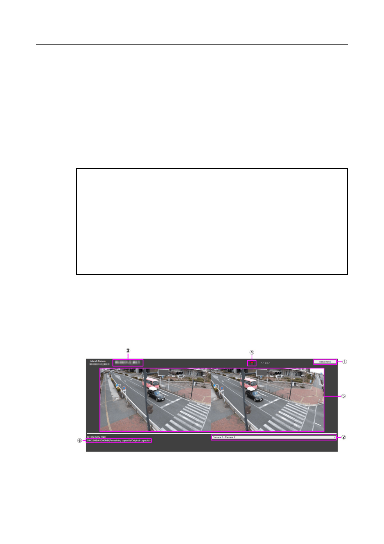
・When the Authentication dialog appears, enter the administrator's or general
user's username and password. Depending on the mobile phone, the password
may need to be entered each time the screen is switched.
・Depending on the tablet terminal, the image may not be displayed when the size o
f
the image is large. This may be displayed when the [Image quality setting] of
[JPEG] is close to low quality.
→10.2 [Image] for setting JPEG images
・You may not be able to access some tablets and contract plans.
*1 The IP address is the global IP address on the WAN side of the router that can be accessed
from the Internet.
Note, however, that this is the local IP address when accessing the handset in the same LAN
with a mobile terminal supporting wireless connection.
*2 Only for accessing the computer via the Internet.
*3 It is available only for users whose access levels are set to [1. Administrator].
*4 When [User auth.] is set to [On], only users with access levels set to [1. Administrator] or [2.
Camera control] can work.
→15.1 [User auth.] to configure user-authentication
2.4.2.3 Viewing Multi-directional Camera Images from a Tablet Terminal
1 [http://IP address] on the tablet terminal
*1
Or [host name/ registered in the http://DDNS
server]
*2
The image of the computer is displayed when you enter it and connect it to the
computer.
2 Operation
2.4 Viewing images from mobile/tablet terminals
124
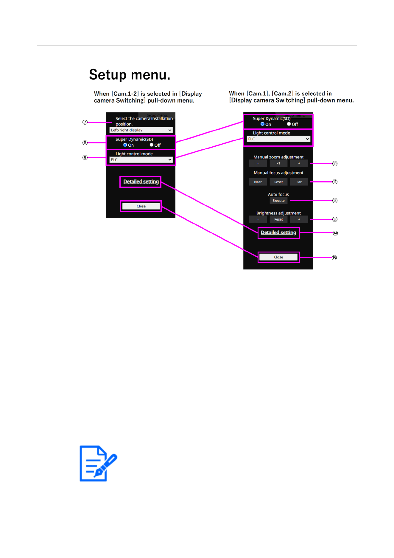
[Note:]
・The blinking of the alarm notification button is not linked to the alarm notification
operation such as recording to the SD Memory Card or mail transfer. Check the
setting of each operation.
①[Setup menu.] buttons*3
Indicates the setup menu.
②[Switch Display Camera] pull down menu
The camera image displayed in the area ⑤ can be selected.
[Camera 1 to Camera 2]:Images of camera 1 and 2 are displayed at the same time. Displayed
according to the settings in [⑦ Layout Setup pull-down Menu].
[Camera 1]:Image of camera 1 is displayed as a single image.
[Camera 2]:Image of camera 2 is displayed as a single image.
③[Camera title]
The title of the camera entered in [Camera title] on the [Basic] tab is displayed.
→3.2 [Basic] to perform basic settings
④[Alarm Notification] button*4
The lamp blinks when an alarm is generated. Click the button to disappear.
2 Operation
2.4 Viewing images from mobile/tablet terminals
125

[Note:]
・Set [Super Dynamic] to [Off] when the following phenomena are observed
depending on the lighting condition.
-when flickering or color changes occur
-when noise is generated in the bright area of the screen
[Note:]
・The zoom (magnification) switches between the optical zoom and EX optical
zoom.
⑤[Main area]
Live displays the camera image.
⑥[Capacity display]
The remaining capacity and total capacity of the SD Memory Card are displayed.
⑦[Layout Settings] pull-down menu
Select [Left/right display] or [Up/down display] as the layout of images to be displayed in the
area ⑤. The Layout Setting pull-down menu is displayed when [Camera 1-Camera 2] is
selected in the Display Camera Switching pull-down menu.
[Left/right display]: Images of cameras 1 and 2 are displayed in left-right alignment.
[Up/down display]: Images of cameras 1 and 2 are displayed in the upper and lower positions.
⑧[Super dynamic setting]
You can set [On] or [Off] to activate the super dynamic function. You can set for each preset
position. See [What is Super Dynamic] for details on super dynamic.
[On]:The Super Dynamic function is activated.
[Off]:Stops the superdynamic function.
⑨[Light control mode] pull-down menu
Select the mode to control the light intensity from the following.
[Flickless (50 Hz)]/[Flickless (60 Hz)]:Flicker is automatically corrected with a fluorescent
lamp. 50 Hz/60 Hz will be used differently in different regions.
ELC:The electronic shutter is used to control the light intensity.
⑩[Manual zoom adjustment]
Adjust the zoom manually.
[-]: Adjust the zoom factor to 1.0 times in the [Wide angle] direction.
[x1]: Zoom (magnification) is 1.0 times.
[+]: Adjust the zoom factor in the [Telephone] direction.
2 Operation
2.4 Viewing images from mobile/tablet terminals
126

[Important]
・With the Mask area, Privacy zone, VMD area, SCD area, and VIQS area set,
setting the EX optical zoom will shift the position. Therefore, set the EX optical
zoom and then set each area.
→10.4.2 Set the mask area
→10.4.6 Setting the privacy zone (Privacy zone setting screen)
→14.6 [VMD area] to set the motion detection area
→14.8 [SCD area] to set up SCD area
→10.4.8 Set up the VIQS area
[Note:]
・One-click on the [Near] or [Far] buttons may appear to have no change in focus
due to trace adjustments. If you want to move the focus position large, press and
hold the button for a long time.
[Important]
・If auto focus is executed while the slow shutter is running (e.g. at night) with the
[Maximum shutter] set to a longer time than [1/30s maximum] (2/30s maximum],
[4/30s maximum], [6/30s maximum], [10/30s maximum], or [16/30s maximum]),
it may take a lot of time to complete auto focus.
・The focus may not be adjusted automatically in the following locations or subject.
In this case, adjust the focus manually.
-Be a big move
-Large variation in illumination
-Low illumination-Extremely bright or reflected light
-Over the window
-where the dome cover is prone to contamination
⑪[Manual focus adjustment]
Adjust the focus manually.
[Near]: Adjust the focus to the [Near].
[Reset] returns focus (focus) to its default settings.
[Far]: Adjust the focus to the [Far].
⑫[Auto focus]
When [Execute] is clicked, the auto focus function is activated to automatically adjust the focus
to the subject in the center of the picture.
2 Operation
2.4 Viewing images from mobile/tablet terminals
127

-White walls are less dark.
-Flicker fiercely
・When the image is switched from color to black and white in the near infrared
region, the focus may shift due to the optical characteristics. If [Focusing at Day
& Night switching] is set to [Auto] or [Preset], the camera can focus automatically
(it does not support the lighting change after the focus operation is completed).
[Note:]
・When accessing the advanced settings screen on a tablet device, some
operations are not available, such as long-pressing zoom and focus does not work
or the slide bar cannot be moved.
[Note:]
・If the HTTP port number is changed from 80, [http://IP address:port number/]
*1
Enter the port number of the machine. If the DDNS function is used, [http://Host
name registered on the DDNS server: Port number/]
*3
Please enter.
・If you are configuring [HTTPS] in [HTTPS]-[Connection] on the [Advanced] tab
of the Network Page, enter the following.
[https://IP address:port number/] or [host name registered on the https://
DDNS server: port number/]
・When the Authentication dialog appears, enter the administrator's or general
user's username and password. Depending on the mobile phone, the password
may need to be entered each time the screen is switched.
・Sound cannot be received from a tablet terminal.
⑬[Brightness adjustment] buttons
Adjust the brightness. The [Brightness adjustment] buttons are not displayed when [Camera 1
to Camera 2] is selected in the Show Camera switching pull-down menu.
Press the [Light (+)] button to brighten the image.
Press the [Dark (-)] button to darken the image.
Press [Reset] to return to the default brightness.
⑭[Detailed setting] button
The Detailed setting screen is displayed in a new tab.
→5.3 Camera Advanced Menu Screen
⑮[Close] buttons
Hides the Setup menu.
2 Operation
2.4 Viewing images from mobile/tablet terminals
128
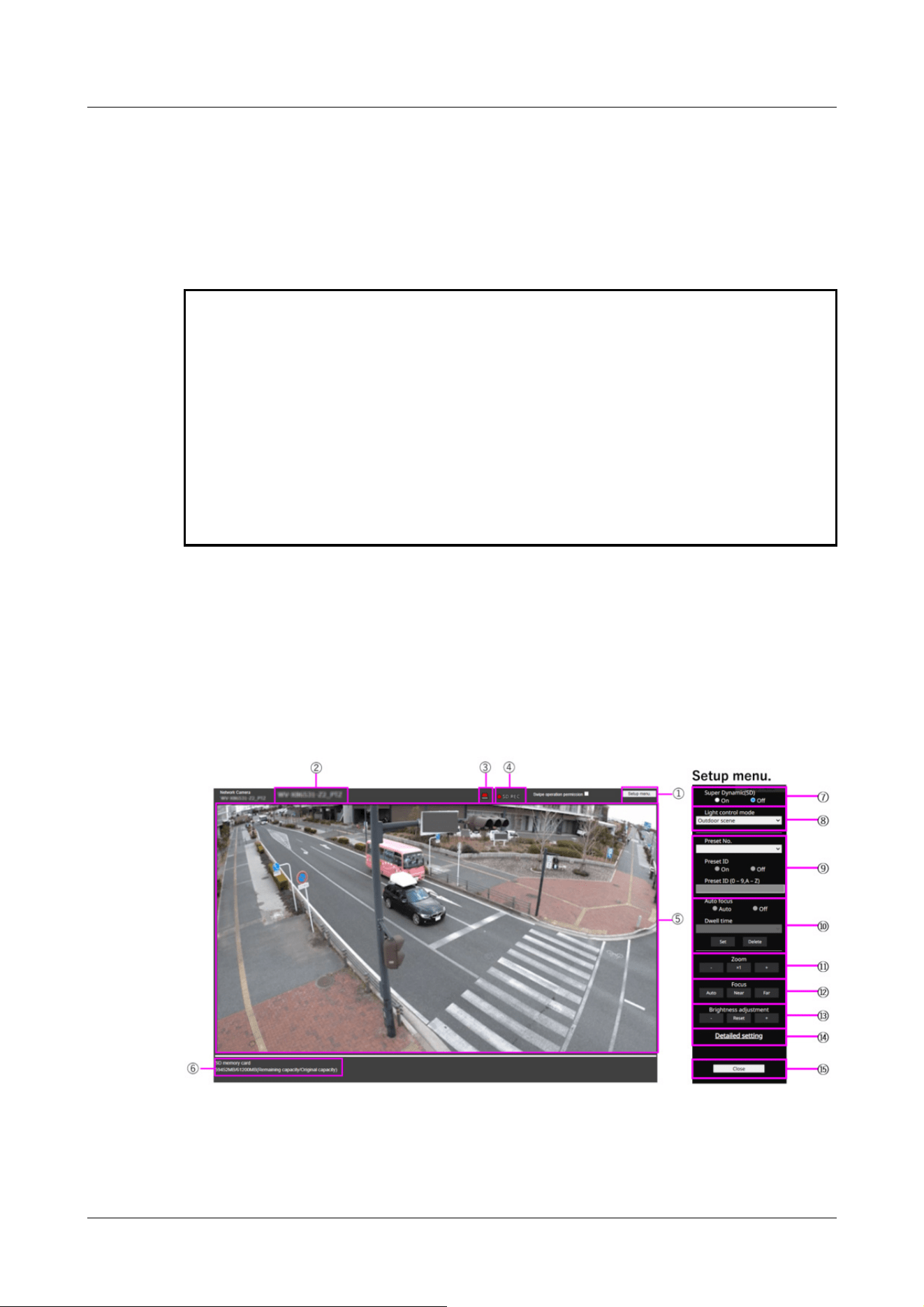
・Depending on the tablet terminal, the image may not be displayed when the size o
f
the image is large. This may be displayed when the [Image quality setting] of
[JPEG] is close to low quality.
・You may not be able to access some tablets and contract plans.
*1 The IP address is the global IP address on the WAN side of the router that can be accessed
from the Internet.
Note, however, that this is the local IP address when accessing the handset in the same LAN
with a mobile terminal supporting wireless connection.
*2 Only for accessing the computer via the Internet.
*3 It is available only for users whose access levels are set to [1. Administrator].
*4 When [User auth.] is set to [On], only users with access levels set to [1. Administrator] or [2.
Camera control] can work.
→15.1 [User auth.] to configure user-authentication
2.4.2.4 Viewing images of the Multi-directional/PTZ camera from the tablet terminal
PTZ camera
1 [http://IP address] on the tablet terminal
*1
Or [host name/ registered in the http://DDNS
server]
*2
The image of the computer is displayed when you enter it and connect it to the
computer.
①[Setup menu.] buttons*3
Indicates the setup menu.
2 Operation
2.4 Viewing images from mobile/tablet terminals
129

[Note:]
・The alarm notification button blinks in conjunction with the alarm notification
operation such as mail transfer. Check the operation setting.
[Note:]
・Set [Super Dynamic] to [Off] when the following phenomena are observed
depending on the lighting condition.
-when flickering or color changes occur
-when noise is generated in the bright area of the screen
・If [Light control mode] is set to [Fix shutter], [Super Dynamic] cannot be set to
[On].
・When [Stabilizer] is set to [On], the superdynamic setting is [Off].
②[Camera title]
The title of the camera entered in [Camera title] on the [Basic] tab is displayed.
→3.2 [Basic] to perform basic settings
③[Alarm Notification] button*4
The lamp blinks when an alarm is generated. Click the button to disappear.
④[SD Storage Status Display]
Displays the storage status on the SD Memory Card. When saving starts, the SD save status
indicator turns red. The LED turns OFF when saving stops.
This is displayed when the [Save trigger] in the Setup menu is set to [Manual] or [Schedule].
→9.2 [SD memory card] for setting SD Memory Cards
⑤[Main area]
Live displays the camera image.
⑥[Capacity display]
The remaining capacity and total capacity of the SD Memory Card are displayed.
⑦[Super dynamic setting]
You can set [On] or [Off] to activate the super dynamic function. You can set for each preset
position. This cannot be set when [Image capture mode] is in [60 fps mode] or [50 fps mode].
See [What is Super Dynamic] for details on super dynamic.
[On]:The Super Dynamic function is activated.
[Off]:Stops the superdynamic function.
⑧[Light control mode] pull-down menu
Select the mode to control the light intensity from the following.
2 Operation
2.4 Viewing images from mobile/tablet terminals
130

[Note:]
・If you increase the shutter speed (~1/10,000), you will be less prone to blur
even when the subject moves faster.
・Increasing the shutter speed decreases the sensitivity.
・If [Super Dynamic] is set to [On], [Fix shutter] cannot be set. To configure [Fix
shutter], set [Super Dynamic] to [Off].
・[Indoor scene(60Hz)] cannot be set when [Image capture mode] is in 25fps, 50fps,
or 12.5fps modes.
[Outdoor shooting]:The brightness (illumination) controls the light intensity by combining the
electronic shutter and automatic aperture. This setting is used when shooting bright subjects
such as outdoors. Be careful not to flicker under fluorescent lights, etc.
[Flickless (50 Hz)]/[Flickless (60 Hz)]:Flicker is automatically corrected with a fluorescent
lamp. 50 Hz/60 Hz will be used differently in different regions.
[Fixed shutter]:
If [Image capture mode] is in 30 fps or 15 fps mode:
[1/30 fixed], [3/120 fixed], [2/100 fixed], [2/120 fixed], [1/100 fixed], [1/120 fixed], [1/250
fixed], [1/500 fixed], [1/1000 fixed], [1/2000 fixed], [1/4000 fixed], or [1/10000 fixed]
If [Image capture mode] is in 25 fps or 12.5 fps mode:
[1/25 fixed]/[3/100 fixed]/[2/100 fixed]/[1/100 fixed]/[1/250 fixed]/[1/500 fixed]/[1/1000
fixed]/[1/2000 fixed]/[1/4000 fixed]/[1/10000 fixed]
When [Image capture mode] is 60 fps:
[1/60 fixed]/[1/100 fixed]/[1/120 fixed]/[1/250 fixed]/[1/500 fixed]/[1/1000 fixed]/[1/2000
fixed]/[1/4000 fixed]/[1/10000 fixed]
If [Image capture mode] is in 50fps mode:
[1/50 fixed]/[1/100 fixed]/[1/250 fixed]/[1/500 fixed]/[1/1000 fixed]/[1/2000 fixed]/[1/4000
fixed]/[1/10000 fixed]
⑨[Preset position setting]
Set the preset position.
Before registering the preset, move the camera in the direction you want to register.
To change the orientation of the camera, enable [Swipe operation permission] and select the
image position to be centered on the image angle. The camera's orientation moves to a position
centered on the clicked position.
If you want to zoom in, enable [Swipe operation permission] and select the zoom area in the
picture.
2 Operation
2.4 Viewing images from mobile/tablet terminals
131

[Important]
・When registering a preset position using a tablet, pay attention to the following.
-If updating of the image on the tablet is slow, it is recommended that you register
the preset while viewing the image on the confirmation monitor.
-If you resize the screen with tablet operation, you may not be able to change the
orientation or zoom in on the screen.
-If you cannot adjust the orientation of the camera with the tablet operation, refer
to the following to move the camera orientation in the direction you want to
register.
→2.4.1 Viewing images from mobile devices (smartphones, etc.)
[Important]
・If you set [Preset ID], be sure to press [Register].
[Note:]
・When set to [On], the position name is displayed where you set the position in
[Camera title position] on the [Basic] tab.
[Important]
・If you set [Preset ID (0 – 9,A – Z)], be sure to press [Register].
Preset No.
Set the position number to be registered.
Preset ID
Use [On] and [Off] to set whether the position name is displayed. You can set for each preset
position.
[On]:Displays the position name.
[Off]:The position name is not displayed.
Preset ID (0-9,A-Z)
Enter the name to be displayed on the image. You can set for each preset position.
Number of characters that can be entered:0 to 40 characters
Input Characters:0-9 (single-byte), A-Z (single-byte, uppercase, lowercase), double-byte,
single-byte symbol ! " # $ % & ' ( ) * + , ‑ . / : ; = ?
2 Operation
2.4 Viewing images from mobile/tablet terminals
132

[Note:]
・The position name entered is displayed next to the preset position number in the
pull-down. If [Preset ID] is set to [On], it can also be displayed on the images.
[Note:]
・When presetting a subject whose depth does not change, a subject whose
contrast is low, or a subject with high brightness such as a spotlight, etc., set
[Off] and register the preset position after setting the focus.
[Note:]
・The preset position set to [Off] does not move to that position during the preset
sequence, but instead moves to the next preset position.
・Depending on the stop time setting, the watch may move to the next preset
position during auto focus operation.
・If the preset sequence function is used for a long time, the drive parts may be
consumed and the replacement cycle of consumables may be faster. For
consumables, refer to the Web Guide.
⑩[Auto focus]
Use [Auto] and [Off] to set whether auto focus is performed after the preset is moved. You can
set for each preset position.
[Auto]:Auto focus is performed after the preset is moved.
[Off]:Auto focus is not performed after moving the preset.
[Stopping time]
During the preset sequence operation, select the time to reflect the image of each preset
position (the time when the camera stops rotating) from the following.
[5s]/ [10s]/ [15s]/ [20s]/ [25s]/ [30s]
⑪[Zoom]
Adjust the zoom manually.
[-]:Adjust the zoom factor to 1.0 times in the [Wide Angle] direction.
[x1]: Zoom (magnification) is 1.0 times.
[+]:Adjust the zoom factor in the [Telescope] direction.
⑫[Focus]
Adjust the focus manually.
[Auto]:Automatically adjust focus.
2 Operation
2.4 Viewing images from mobile/tablet terminals
133

[Note:]
・The following subjects cannot be focused with auto focus. Focus manually.
-Bright or intense light reflecting subjects
-Subject over water droplets or dirty glass
-Remote and nearby subjects mixed together
-Subjects (white walls, etc.) without contrast
-horizontal subject such as a blind
-Oblique subject
-Dark subject
[Note:]
・When accessing the advanced settings screen on a tablet device, some
operations are not available, such as long-pressing zoom and focus does not work
or the slide bar cannot be moved.
[Note:]
・If the HTTP port number is changed from 80, [http://IP address:port number/]
*1
Enter the port number of the machine. If the DDNS function is used, [http://Host
name registered on the DDNS server: Port number/]
*3
Please enter.
・If you are configuring [HTTPS] in [HTTPS]-[Connection] on the [Advanced] tab
of the Network Page, enter the following.
[https://IP address:port number/] or [host name registered on the https://
DDNS server: port number/]
,
[Near]:Adjust the focus to the [Near].
[Far]:Adjust the focus to the [Far].
⑬[Brightness adjustment] buttons
Adjust the brightness.
Press the [Light (+)] button to brighten the image.
Press the [Dark (-)] button to darken the image.
Press [Reset] to return to the default brightness.
⑭[Detailed setting] button
The Detailed setting screen is displayed in a new tab.
→5.3 Camera Advanced Menu Screen
⑮[Close] buttons
Hides the Setup menu.
2 Operation
2.4 Viewing images from mobile/tablet terminals
134

・When the Authentication dialog appears, enter the administrator's or general
user's username and password. Depending on the mobile phone, the password
may need to be entered each time the screen is switched.
・Depending on the tablet terminal, the image may not be displayed when the size o
f
the image is large. This may be displayed when the [Image quality setting] of
[JPEG] is close to low quality.
→10.2 [Image] for setting JPEG images
・You may not be able to access some tablets and contract plans.
*1 The IP address is the global IP address on the WAN side of the router that can be accessed
from the Internet.
Note, however, that this is the local IP address when accessing the handset in the same LAN
with a mobile terminal supporting wireless connection.
*2 Only for accessing the computer via the Internet.
*3 It is available only for users whose access levels are set to [1. Administrator].
*4 When [User auth.] is set to [On], only users with access levels set to [1. Administrator] or [2.
Camera control] can work.
→15.1 [User auth.] to configure user-authentication
Multi-directional camera
1 [http://IP address] on the tablet terminal
*1
Or [host name/ registered in the http://DDNS
server]
*2
The image of the computer is displayed when you enter it and connect it to the
computer.
2 Operation
2.4 Viewing images from mobile/tablet terminals
135
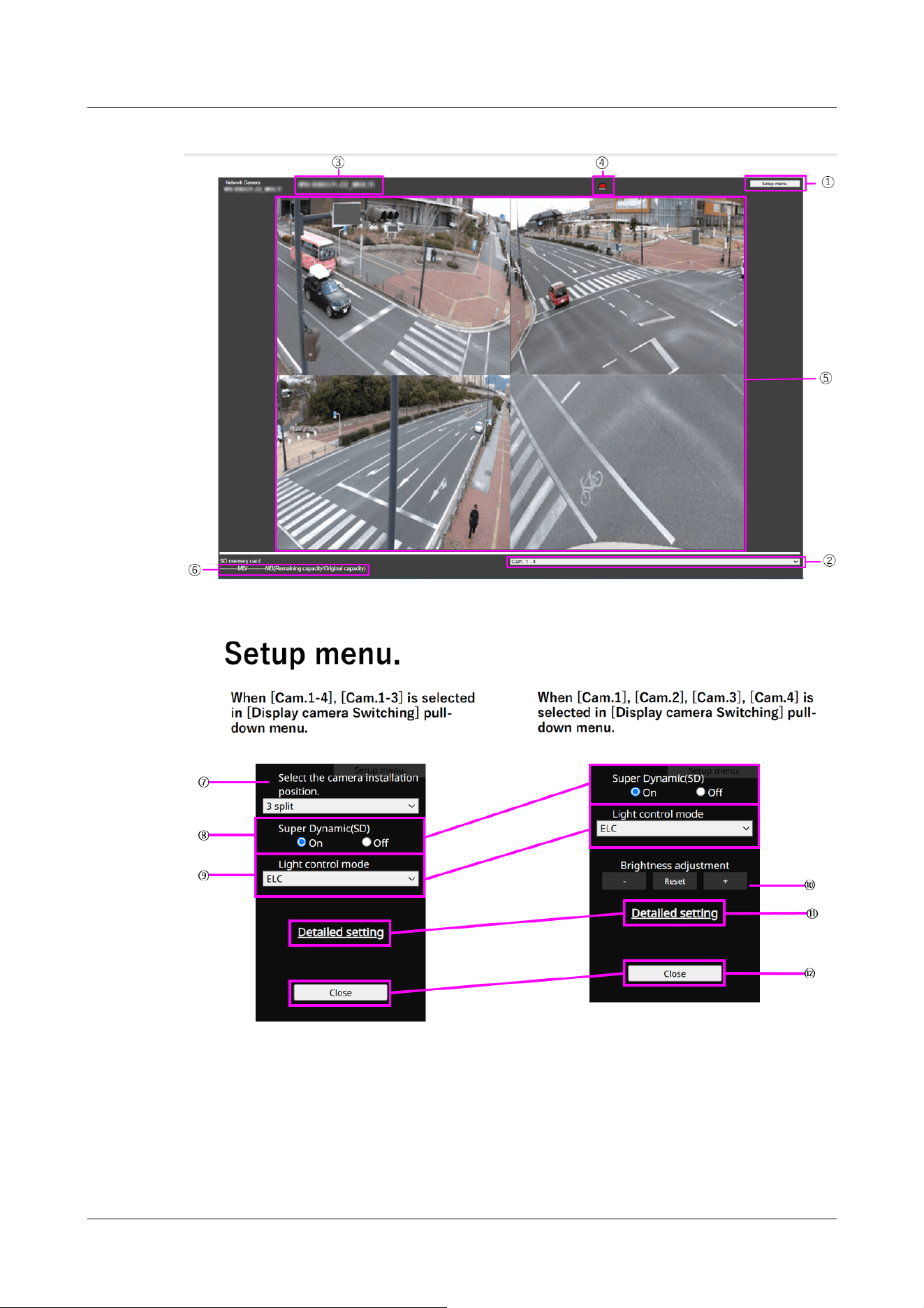
①[Setup menu.] buttons*3
Indicates the setup menu.
②[Switch Display Camera] pull down menu
The camera image displayed in the area ⑤ can be selected.
2 Operation
2.4 Viewing images from mobile/tablet terminals
136

[Note:]
・The blinking of the alarm notification button is not linked to the alarm notification
operation such as recording to the SD Memory Card or mail transfer. Check the
setting of each operation.
[Camera 1 to Camera 4]:Images of camera 1, 2, 3 and 4 are displayed at the same time.
Displayed according to the settings in [⑦ Layout Setup pull-down Menu].
[Camera 1 to Camera 3]:Images of camera 1, 2 and 3 are displayed at the same time. Displayed
according to the settings in [⑦ Layout Setup pull-down Menu].
[Camera 1]:Image of camera 1 is displayed as a single image.
[Camera 2]:Image of camera 2 is displayed as a single image.
[Camera 3]:Image of camera 3 is displayed as a single image.
[Camera 4]:The image of camera 4 is displayed as a single image.
③[Camera title]
The title of the camera entered in [Camera title] on the [Basic] tab is displayed.
→3.2 [Basic] to perform basic settings
④[Alarm Notification] button*4
The lamp blinks when an alarm is generated. Click the button to disappear.
⑤[Main area]
Live displays the camera image.
⑥[Capacity display]
The remaining capacity and total capacity of the SD Memory Card are displayed.
⑦[Layout Settings] pull-down menu
Select from [4 split], [360 deg.] and [270 deg.] for the layout of the images to be displayed in
the area ⑤. The Layout Setting pull-down menu is displayed when [Camera 1] to [Camera 4]
and [Camera 1] to [Camera 3] are selected from the Display Camera Switching pull-down menu.
[360-degree shooting]:Images of camera 1, 2, 3, and 4 are displayed side by side. Select this
when you want to place camera 4 horizontally, such as when you want to take a wide range of
pictures.
[270-degree shooting]:Images of camera 1, 2, and 3 are displayed side by side. Select this when
you want to shoot a wide area.
[Divide into four pieces]:Images of cameras 1, 2, 3, and 4 are displayed in quadrants.
⑧[Super dynamic setting]
You can set [On] or [Off] to activate the super dynamic function. You can set for each preset
position. See [What is Super Dynamic] for details on super dynamic.
[On]:The Super Dynamic function is activated.
2 Operation
2.4 Viewing images from mobile/tablet terminals
137

[Note:]
・Set [Super Dynamic] to [Off] when the following phenomena are observed
depending on the lighting condition.
-when flickering or color changes occur
-when noise is generated in the bright area of the screen
[Note:]
・When accessing the advanced settings screen on a tablet device, some
operations are not available, such as long-pressing zoom and focus does not work
or the slide bar cannot be moved.
[Note:]
・If the HTTP port number is changed from 80, [http://IP address:port number/]
*1
Enter the port number of the machine. If the DDNS function is used, [http://Host
name registered on the DDNS server: Port number/]
*3
Please enter.
・If you are configuring [HTTPS] in [HTTPS]-[Connection] on the [Advanced] tab
of the Network Page, enter the following.
:
:
]
:
[Off]:Stops the superdynamic function.
⑨[Light control mode] pull-down menu
Select the mode to control the light intensity from the following.
[Flickeress (50 Hz)/[flickeress (60 Hz)]:Flicker is automatically corrected with a fluorescent
lamp. 50 Hz/60 Hz will be used differently in different regions.
ELC:The electronic shutter is used to control the light intensity.
⑩[Brightness adjustment] buttons
Adjust the brightness. [Brightness adjustment] buttons are not displayed when [Camera 1] to
[Camera 4] and [Camera 1] to [Camera 3] are selected from the [Display Camera Selection]
pull-down menu.
Press the [Light (+)] button to brighten the image.
Press the [Dark (-)] button to darken the image.
Press [Reset] to return to the default brightness.
⑪[Detailed setting] button
The Detailed setting screen is displayed in a new tab.
→5.3 Camera Advanced Menu Screen
⑫[Close] buttons
Hides the Setup menu.
2 Operation
2.4 Viewing images from mobile/tablet terminals
138

[https://IP address:port number/] or [host name registered on the https://
DDNS server: port number/]
・When the Authentication dialog appears, enter the administrator's or general
user's username and password. Depending on the mobile phone, the password
may need to be entered each time the screen is switched.
・Sound cannot be received from a tablet terminal.
・Depending on the tablet terminal, the image may not be displayed when the size o
f
the image is large. This may be displayed when the [Image quality setting] of
[JPEG] is close to low quality.
・You may not be able to access some tablets and contract plans.
*1 The IP address is the global IP address on the WAN side of the router that can be accessed
from the Internet.
Note, however, that this is the local IP address when accessing the handset in the same LAN
with a mobile terminal supporting wireless connection.
*2 Only for accessing the computer via the Internet.
*3 It is available only for users whose access levels are set to [1. Administrator].
*4 When [User auth.] is set to [On], only users with access levels set to [1. Administrator] or [2.
Camera control] can work.
→15.1 [User auth.] to configure user-authentication
[Note:]
・The items that can be set differ depending on the function of the model.
・Refer to the catalog specifications for the functions installed in each model.
・[MULTI] [Recording format] can be set only for streams.
2.5 Manually save images on the SD memory card
You can manually save the image on the live image page to the SD Memory Card.
This function is available only when [Save trigger] is set to [Manual] by clicking the [SD memory
card] tab on the Basic page of the Advanced Menu.
In the [Recording format] of the Advanced menus, you can select either JPEG or Stream to save.
If JPEG is selected in [Recording format], a still image is saved. If JPEG is selected, a movie is
saved.
2 Operation
2.5 Manually save images on the SD memory card
139

・[MULTI] Manually saves all camera movies at the same time.
・SD recording is not available when [Image capture mode] is set to [60fps Mode]
or [50fps Mode].
[Note:]
・Images saved on the SD Memory Card can be downloaded from the Log List
screen to the PC by clicking the [Start] button on the [Log/Play] button on the
Live screen.
The download function allows saving to the PC.
→2.8.1 When playing JPEG images stored on the SD Memory Card
→2.8.2 Play back the image of the stream stored on the SD Memory Card
The destination for storing image data is the fixed directory in the SD Memory
Card.
→20.3 Directory structure of SD Memory Card
・If you click the [Stop] button and then immediately click the [Start] button, the
image may not be saved. If so, click [Start] again.
・To use this function correctly, format the SD Memory Card on your computer
before using the SD Memory Card.
1 Live image pages are displayed.
→2.3.1 View camera images
2 Click [Camera control] to view the [Camera control] panels.
3 [SD memory card]-starts saving to the SD Memory Card by clicking [Start] on the [Rec. on
SD]. The SD save status indicator turns red during storage.
→2.3.2 About live image pages
The saved intervals are set on the [SD memory card] tabs of the basic pages.
→9.2 [SD memory card] for setting SD Memory Cards
4 To stop storing images on the SD Memory Card, press the [Stop] buttons for [SD memory
card]-[Rec. on SD]. The SD save status indicator turns OFF when saving is stopped.
5 Close the Camera Control Panel by clicking [Camera control].
2.6 Operation when alarm is generated
When the following alarms are generated, the machine performs an alarm operation according to
the setting (camera operation associated with alarm generation).
2 Operation
2.6 Operation when alarm is generated
140

2.6.1 Alarm type
[Terminal alarm]:When an alarm device such as a sensor is connected to the alarm input terminal,
an alarm is activated when the connected alarm device operates.
[VMD alarm]:When a change (movement) is detected in the image in the set VMD area, an alarm
is activated.
* Operation detection: VMD (Video Motion Detector) = Motion detection, Motion detector
function
[Scene change detection (SCD) alarm]:The alarm is activated when the subject is changed by
covering the camera with a cloth or a lid, or changing the camera direction significantly.
[Command alarm]:When a unique alarm notification is received from the connected device via the
network, an alarm is activated.
[Audio detection alarm]:An alarm is activated when the set sound detection threshold is exceeded.
[Impact detection alarm]: When the set threshold for impact detection is exceeded, the alarm is
activated.
[Casing open detection alarm]: Alarm is activated when the front cover of the camera is opened or
closed.
Alarm Notification from Function Extension Software:When the function extension software with
an alarm function is installed, an alarm is activated when an alarm is generated by the function
extension software.
2.6.2 Operation when alarm is generated
Displaying alarm notification on live image page
When an alarm is generated, the alarm notification is displayed on the [Live] page.
→2.3.2 About live image pages
Notify the device connected to the output terminal of the alarm
When an alarm is activated, a signal can be output from the output terminal to sound an alarm,
etc. The outputs are set on the [Alarm] tabs of the alarm pages.
→14.2 [Alarm] for setting the output terminal
Save images on the SD Memory Card
When an alarm is activated, images (JPEG/H.265/H.264) are saved on the SD Memory Card. To
save images on the SD Memory Card, use the [SD memory card] tab on the basic page and the
[Alarm] tab on the alarm page.
→9.2 [SD memory card] for setting SD Memory Cards
→14.1 [Alarm] to set alarm operation
2 Operation
2.6 Operation when alarm is generated
141

[Note:]
・The items that can be set differ depending on the function of the model.
・Refer to the catalog specifications for the functions installed in each model.
Notify the alarm by e-mail
When an alarm is generated, an e-mail notifying that an alarm has occurred (alarm notification) is
sent to the previously registered e-mail address. You register up to four mail messages to send
alarms. You can also attach a still image to send an alarm mail. Alarm mail is set on the [Alarm] tab
of the alarm page and on the [Advanced] tab of the network page.
→14.1 [Alarm] to set alarm operation
→16.2.1 Set mail sending
Notifies that an alarm has occurred at the specified address (unique alarm notification)
This function is useful when using devices manufactured by us (network disk recorder, etc.). When
[TCP alarm notification] is set to [On], the computer can be notified that it is in the alarm
condition. You can set your own alarms by using the [Notification] tabs on the alarm pages.
→14.12.1 Set unique alarm notification
Notifying that an alarm has occurred on the specified HTTP server (HTTP alarm notification)
When an alarm is generated, the alarm is sent to the pre-registered HTTP server. You can
register up to five notified HTTP servers. You can also set the URL you want to send to the
HTTP server. The HTTP alarm is set on the [Notification] tab of the alarm page.
→14.12.2 Set the HTTP alarm notification
2.7 Display the log list
The following history is displayed in the list.
Alarm Log:The alarm date and time, recording period, and alarm cause can be checked.
Manual/Schedule Storage Log:You can check the log and recording period when saved manually
or in schedule settings.
1 Live image pages are displayed.
2 Press the [View Camera Control Panel] button to display the camera control panel.
3 SD Memory Card-When the [Start] button of the [Log/Play] is clicked, the Log List window
is displayed in a separate window.
2 Operation
2.7 Display the log list
142
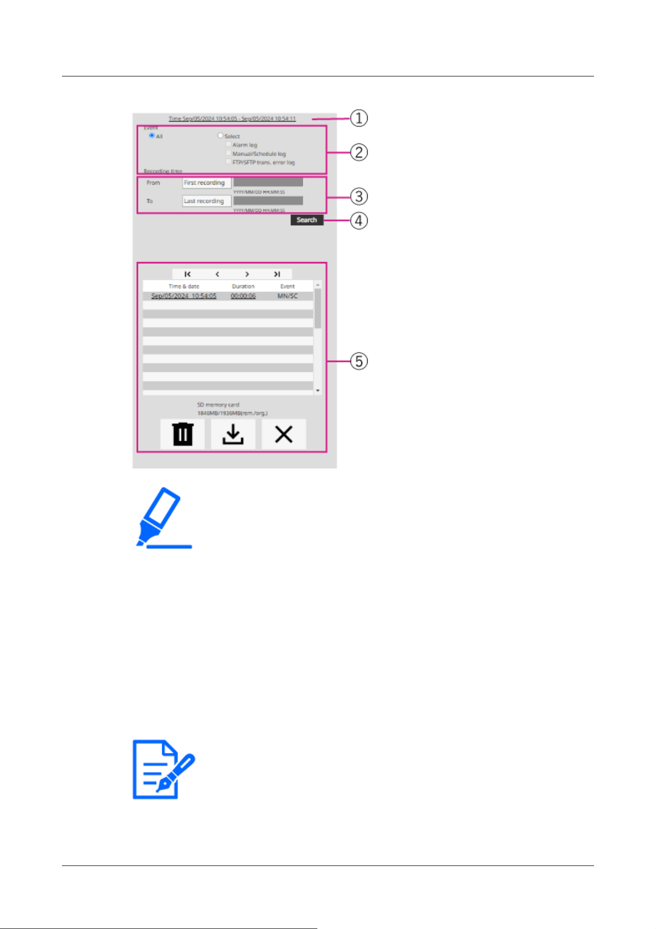
[Important]
・The log list display screen cannot be accessed by multiple users simultaneously.
[Note:]
・[MULTI] Only Multi-directional cameras are selected for recording streams.
・[MULTI] When Image capture mode is in Quad/Dual mode, the recorded images
include all the cameras, so any camera can be searched.
① Recording period
Displays the period of recording saved on the SD Memory Card.
② Recording stream
Select the recording stream in which you want to view the log.
[Camera 1]:For Camera 1, the logs recorded by [Recording stream] are displayed.
[Camera 2]:For Camera 2, the logs recorded by [Recording stream] are displayed.
[Camera 3]:The logs recorded by [Recording stream] are displayed for Camera 3.
[Camera 4]:For Camera 4, the logs recorded by [Recording stream] are displayed.
2 Operation
2.7 Display the log list
143

③ Event
Select the type of log that is displayed in the log list.
[All]:Displays all logs.
[Select]:Only the logs of the selected type are displayed.
– [Alarm Log]:Displays the log when an alarm is generated.
– [Manual/Schedule Save Log]:Displays the log for manual saving and schedule saving.
④ Recording time
Specify the duration of the log to be displayed in the log list.
[From]:Sets the start point of the period to be displayed in the log.
–[First recording]:The first log saved on the SD Memory Card is displayed.
–[Today]:Displays today's logs.
–[Yesterday]:Displays logs from yesterday to today.
–[Last 7 days]:Displays logs from 6 days ago to the present day.
–[Last 30 days]:Displays logs from 29 days ago to today.
–Date/time:Displayed from the date and time log entered in the date and time specification
box.
To:When [First recording] and [Date/time] are set in [Start], set the end of the time period
to be displayed in the log.
–Last recording:Displays the last log saved on the SD Memory Card.
–Date/time:The date and time log entered in the Date and Time Setting box is displayed.
⑤ Search button
[Event] searches for logs according to the condition specified by [Recording time]. The
search results are displayed in the log list.
⑥ Log list
The log search results are displayed. [Time] allows playback of recorded data by clicking
[Record Period].
(top) button:Displays the first log.
(Previous page) button:Displays the log list for the previous page.
(Next page) button:Displays the log list for the following pages.
(Last) button:Displays the last log.
[Time & data]:Displays the date and time the log was recorded.
2 Operation
2.7 Display the log list
144

[Note:]
・If [Time display format] is set to [24h], the alarm date and time is displayed in
24-hour format.
・The timing of logging is as follows.
–[Alarm Log]:The date and time of the alarm is logged.
–[Manual/Schedule Save Log]:The date and time when saving to the SD Memory
Card was started by manual or schedule setting is recorded as a log. To save
continuously, logs are logged at hourly intervals (12 o'clock, 1 o'clock, 2 o'clock,
etc.) when [Recording format] is JPEG. Also, when [Recording format] is
streamed, logs are logged every hour from the beginning of recording.
[Note:]
・The difference between the recording end time and the recording start time is
rounded to the nearest 0.1 second. Therefore, when only one JPEG image is
recorded, the recording time is displayed as 00:00:00.
[Note:]
・The factors displayed differ depending on the function of the model.
・Refer to the catalog specifications for the functions installed in each model.
[Duration]:Displays the length of time data was saved on the SD Memory Card.
[Event]:Displays the cause of the log.
-MN/SC: Logs by Manual Save and Schedule Save
-TRM1: Alarm caused by alarm input to terminal 1
-TRM2: Alarm caused by alarm input to terminal 2
-TRM3: Alarm caused by alarm input to terminal 3
-VMD: Alarm due to operation detection alarm
-SCD: Alarm due to undesired detection alarm
-IMPACT: Alarm by Impact detection alarm
-CASING: Alarm by Opening detection alarm
-COM: Command Alarm
-AT: Alarm due to automatic tracking alarm
-INT: Intrusion alarm by AI-VMD
-LOI: Alarm on AI-VMD
-DIR: Direction alarm with AI-VMD
-CLD: Line cross alarm with AI-VMD
2 Operation
2.7 Display the log list
145

[Important]
・If the SD Memory Card contains a lot of recorded data, it may take several hours
to complete deletion. In such a case, format it. However, all images are deleted by
formatting.
・During deletion, saving by alarm, manual saving, and schedule saving are not
available.
・Do not turn off the power to the computer until deletion is complete.
If the computer power is turned off during operation, data may remain on the SD
Memory Card. In this case, again on the log list screen where the deletion
operation was performed
Click the button.
[Note:]
・You can download up to 50,000 logs per SD Memory Card. If the number exceeds
50,000, it is overwritten from the old log. If the total number of log lists is large, it
may take longer to download.
[Important]
・The image updating speed may be slow during playback or downloading of the
image.
・If the number of images stored on the SD Memory Card is large, it may take a
long time before the images are displayed on the playback page.
・When the aspect ratio is [4:3], the image is displayed in VGA size on the
[SD memory card]:Displays the remaining capacity and total capacity of the SD Memory
Card.
[Delete] button:Deletes the log list for all pages. When searched, the retrieved "b"
Deletes the list only. The image associated with the deleted log list is also deleted.
[Download] button:You can download the total number of logs in the displayed list to the
PC.
[Close] button: Closes the Log List screen.
2.8 Play back images on the SD Memory Card
Click Time in the Log List window to switch the live image page to the Playback page. The display
format varies depending on the [Recording format] of the SD Memory Card.
2 Operation
2.8 Play back images on the SD Memory Card
146

playback page regardless of the resolution of the image stored on the SD Memory
Card. When the aspect ratio is [16:9], the image is displayed in [640x360] on
playback pages regardless of the resolution of the image stored on the SD Memory
Card. Therefore, the playback page may look rough.
・During recording to the SD Memory Card, the playback updating speed may be
slow. • When playing back images recorded in H.265, the recording bit rate may
be displayed at refresh intervals if it is high.
[Note:]
・The items that can be set differ depending on the function of the model.
・Refer to the catalog specifications for the functions installed in each model.
・[MULTI] Multiple cameras cannot be played simultaneously except in Quad/Dual
mode. Playback depends on the camera.
2 Operation
2.8 Play back images on the SD Memory Card
147
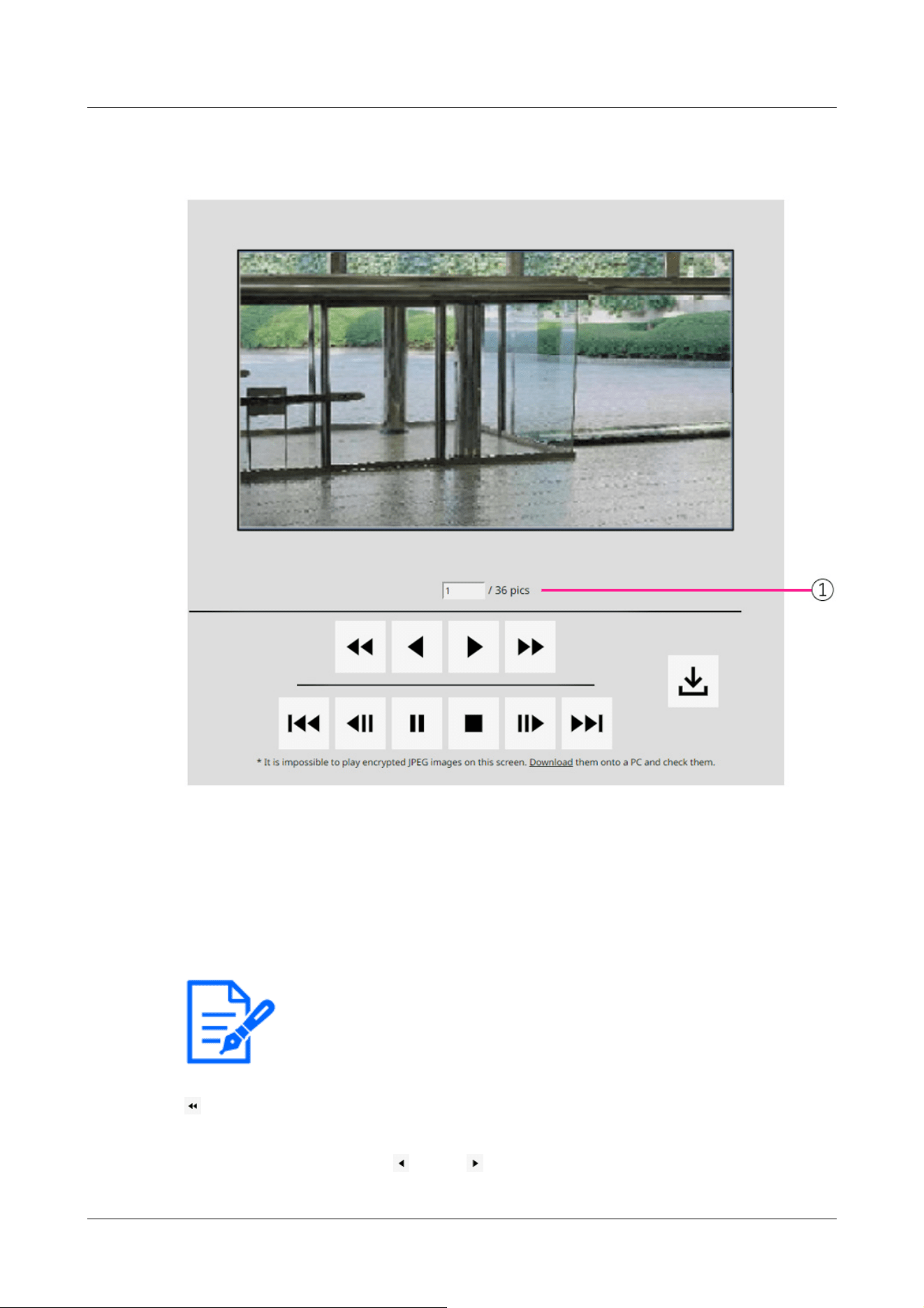
[Note:]
・Enter the number of the image to be displayed and press Enter on the keyboard.
The image with the specified number is displayed on the screen.
2.8.1 When playing JPEG images stored on the SD Memory Card
If the SD Memory Card contains an image associated with the date and time of clicking, the first
image is displayed.
⑧ Number of images
The total number of images saved at the time of clicking and the number of images being
displayed are displayed.
[Fast Reverse Playback] button
Each time the button is clicked, the playback speed is switched.
During high-speed reverse play Buttons, Click the button to return to the normal playback
2 Operation
2.8 Play back images on the SD Memory Card
148

[Note:]
・Press and hold the button to count the number of images.
When the button is released, the countdown of the image number stops and the
image of the number when the button is released is displayed.
speed.
[reverse playback] button
Play back to the previous image.
[Play] button
Play back images in sequence.
[high-speed playback] button
Each time the button is clicked, the playback speed is switched.
During high-speed playback
Buttons, Click the button to return to the normal playback speed.
[top] button
Displays the first image.
[reverse frame advance] button
Click the button during playback to display the previous image and pause it.
Click Pause to display the previous image each time you click the button.
[Pause] button
Click during playback to pause playback.
Click during pause to resume playback.
[Exit] button
Exit the playback and return to the live image page.
[frame advance] button
Click the button during playback to display the following image and pause it.
Click Pause to display the following image for each click of the button.
2 Operation
2.8 Play back images on the SD Memory Card
149
[Note:]
・Press and hold the button to count the number of images. Releasing the button
stops counting up the image number and displays the image of the number when
the button is released.
[Note:]
・During download, the playback screen cannot be operated. Operation should be
completed after downloading.
・If [Cancel] is clicked during download, the download will be cancelled. The video
data downloaded prior to clicking [Cancel] is saved to the computer.
・Since video data is stored in about 60 MB of files, multiple files are downloaded for
data larger than 60 MB.
・H.264 movies saved on a PC can be played back using Windows Media® Player.
Provided, however, that we do not warrant the operation of these software.
・Depending on the status of the SD Memory Card or Windows Media Player,
H.264 movies may not be played.
・For H.265 video playback, please refer to our technical information website
<Control No. C0303>.
[Important]
・Depending on your network environment, downloading of movies may fail. If
playback is in progress, it may be possible to download it by performing it again
after stopping playback.
・Depending on the network environment and the camera status, you may not be
able to perform each operation continuously on this screen.
[Last] button
Shows last image.
[download] button
The selected image is downloaded to the PC.
Check the browser settings used for the destination directory of the PC.
Click the button to display the download window. Click OK in the download window.
2.8.2 Play back the image of the stream stored on the SD Memory Card
2 Operation
2.8 Play back images on the SD Memory Card
150
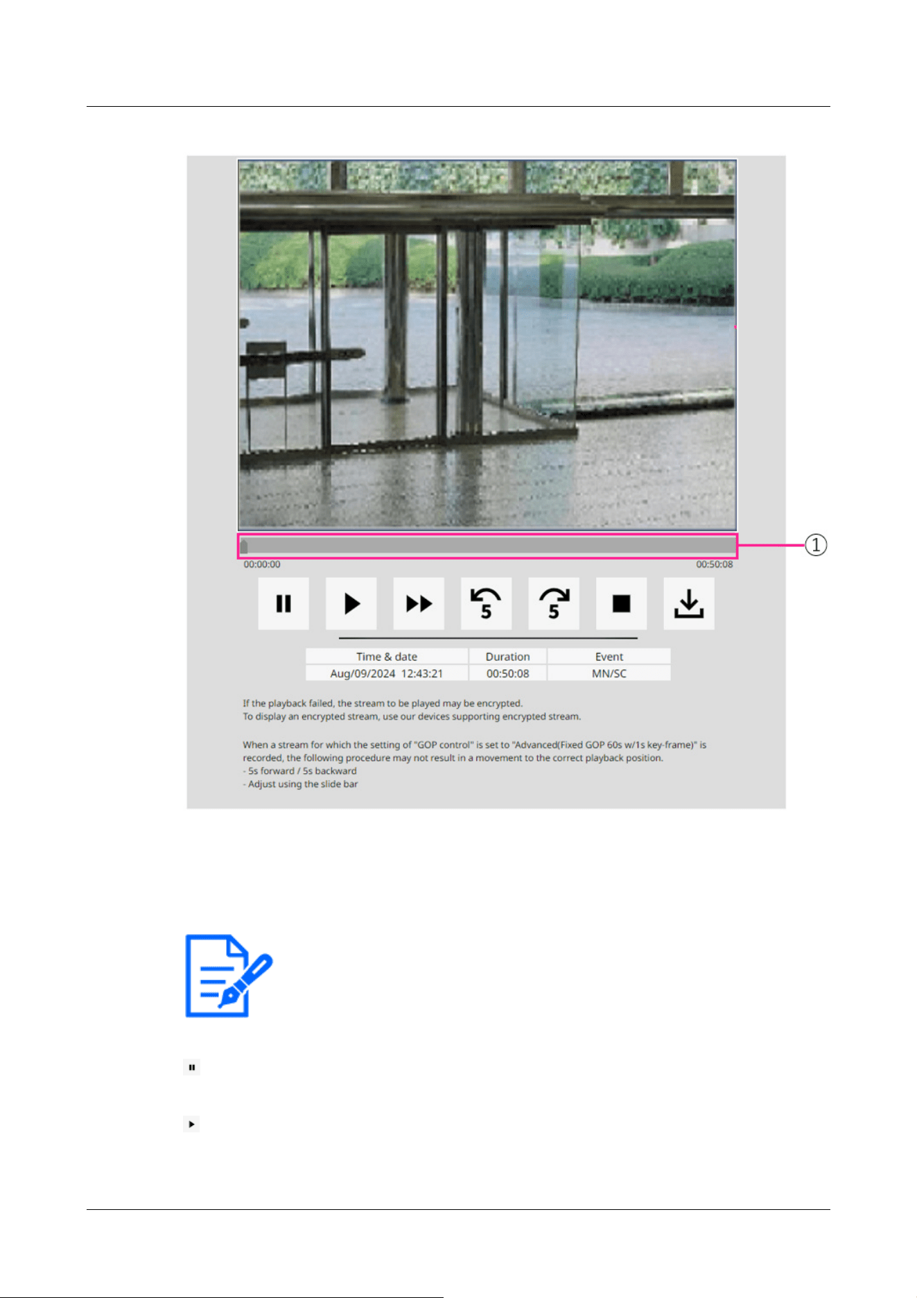
[Note:]
・Move the slider bar to the I-picture at the position where you move it. For this
reason, if streams with [GOP control] set to [Advanced (fixed GOP 60s + 1s
keyframe)] are recorded, the movable position will be 60 seconds apart.
①Slider bar
You can press the slider bar and play it from any position. Operation is available only before
start of playback, during pause, and after completion of playback.
[Pause] button
Click during playback to pause playback.
[Play] button
Play recorded data.
2 Operation
2.8 Play back images on the SD Memory Card
151
[Note:]
・When audio data is recorded, the recorded data is also played, but the image and
sound are not synchronized. Therefore, there may be a slight deviation between
the image and sound. During recording to the SD Memory Card, audio playback
may be interrupted or sound quality may deteriorate.
・When playing back recorded data, the image updating speed of live movies or
playback may be slow.
・If the [Audio transmission mode] in the [Audio] tab of the video/audio pages is
[Off] or [Interactive(Half-duplex)], the recorded data will not be played.
[Note:]
・The maximum speed of high-speed playback depends on the setting of [Stream
recording]-[Max bit rate] on the SD Memory Card.
・During high-speed playback, the recorded data is not played.
・During high-speed playback, the display may be slowed or the display time may be
skipped depending on the setting of [Stream recording]-[Max bit rate].
[Note:]
・If streams with [GOP control] set to [Advanced (Fixed GOP 60s + 1s keyframe)]
are recorded, the playback position may be returned for more than 5 seconds
depending on the length of time the I picture is recorded.
[Note:]
・When the streams set to [Advanced (fixed GOP 60s + 1s keyframe)] in [GOP
control] are recorded, the playback position may be returned depending on the
length of time the I picture is recorded.
[high-speed playback] button
Each time the button is clicked, the playback speed is switched.
During high-speed playback Click the button to return to the normal playback speed.
[5-second return] button
Each time the button is clicked, the returned recorded data is played back 5 seconds before.
[5-second feed] button
Each time the button is clicked, it advances to the next 5 seconds and plays back the recorded
data.
[Exit] button
2 Operation
2.8 Play back images on the SD Memory Card
152

[Note:]
・The content displayed on the [Event] depends on the function of the model.
・Refer to the catalog specifications for the functions installed in each model.
[Note:]
・During download, the playback screen cannot be operated. Operation should be
completed after downloading.
・If [Cancel] is clicked during download, the download will be cancelled. The video
data downloaded prior to clicking [Cancel] is saved to the computer.
・Since video data is stored in about 60 MB of files, multiple files are downloaded for
data larger than 60 MB.
.
.
Exit the playback and return to the live image page.
[Time & data]
Displays the date and time the log was recorded.
[Duration]
Displays the time when the data is saved on the SD Memory Card.
[Event]
Displays the cause of the log.
-MN/SC: logs saved manually and saved in schedule
-TRM1: Alarm due to alarm input to terminal 1
-TRM2: Alarm caused by alarm input to terminal 2
-TRM3: Alarm caused by alarm input to terminal 3
-VMD: Alarm due to operation detection alarm
-SCD: Alarm due to undesired detection alarm
-IMPACT: Alarm by Impact detection alarm
-CASING: Alarm by Opening detection alarm
-COM: Command Alarm
-AT: Alarm due to automatic tracking alarm
-INT: Intrusion alarm by AI-VMD
-LOI: Alarm on AI-VMD
[download] button
The selected recorded data is downloaded to the PC.
Check the browser settings used for the destination directory of the PC.
Click the button to display the download window. Click OK in the download window.
2 Operation
2.8 Play back images on the SD Memory Card
153

・H.264 movies saved on a PC can be played back using Windows Media® Player.
Provided, however, that we do not warrant the operation of these software.
・Depending on the status of the SD Memory Card or Windows Media Player,
H.264 movies may not be played.
・For H.265 video playback, please refer to our technical information website
<Control No. C0303>.
2 Operation
2.8 Play back images on the SD Memory Card
154

・Refer to the catalog specifications for the functions installed in each model.
[Important]
・Configuration panels can only be operated by users with [1. Administrator] access
levels. For details on how to set the access level, refer to the following.
→15.1 [User auth.] to configure user-authentication
3 Setting
This chapter explains the items that can be set from the camera's live image.
You can set general items for each function in live pictures.
For items that cannot be set from live pictures, set them from the Advanced menu.
For how to display live pictures, refer to the following.
→2.3 Viewing images from a PC
For details on how to set each item from the Advanced menu, refer to the following.
→5.3 Camera Advanced Menu Screen
3.1 Displaying the configuration panel from the PC
The main settings of the camera are made on the Setup panel.
3.1.1 How to display
1 Displays Live image pages.
→2.3.1 View camera images
2 In the Live image pages Click the button to display the setting panel.
Press again to hide it. For more information on this panel, please refer to the following.
→3.1.3 Setting Panel Screen
3 Setting
3.1 Displaying the configuration panel from the PC
155
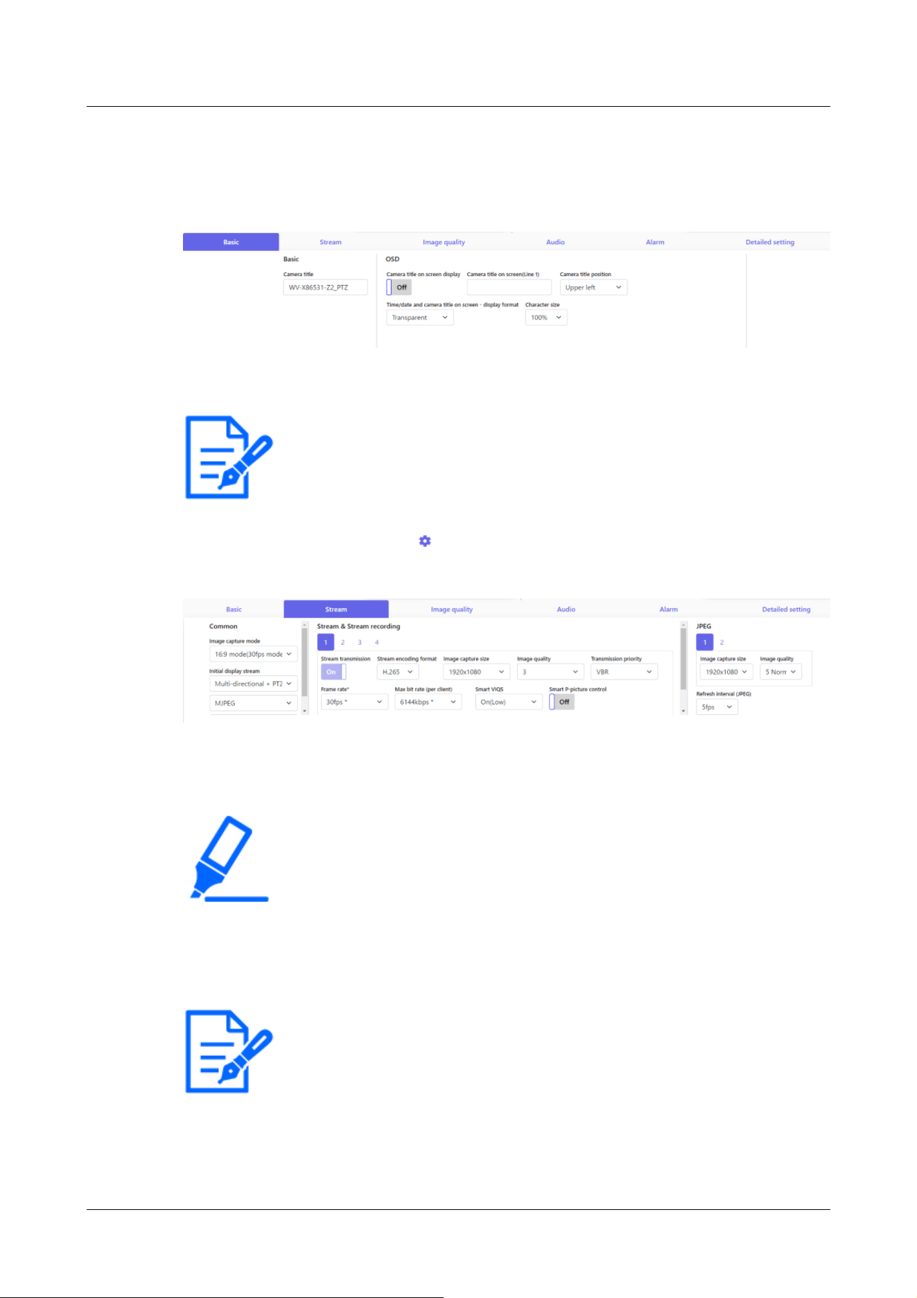
[Note:]
・Some items cannot be set depending on the main area display.
[Important]
・If there are several buttons in the [Set], [Register], and [Execute] pages, click
the [Set], [Register], and [Execute] buttons for each item.
[Note:]
・Refer to the catalog specifications for the functions installed in each model.
3.1.2 How to operate
1 Click on each tab in the Settings panel.
2 Enter each item on the setting page.
If the desired item is not displayed,
Click or press the scroll bar to display the items you want to
set.
3 Once the entry is complete, click to confirm the entry if [Set] is available. Otherwise, it is
confirmed when the set value is selected.
3.1.3 Setting Panel Screen
Fixed cameras
3 Setting
3.1 Displaying the configuration panel from the PC
156
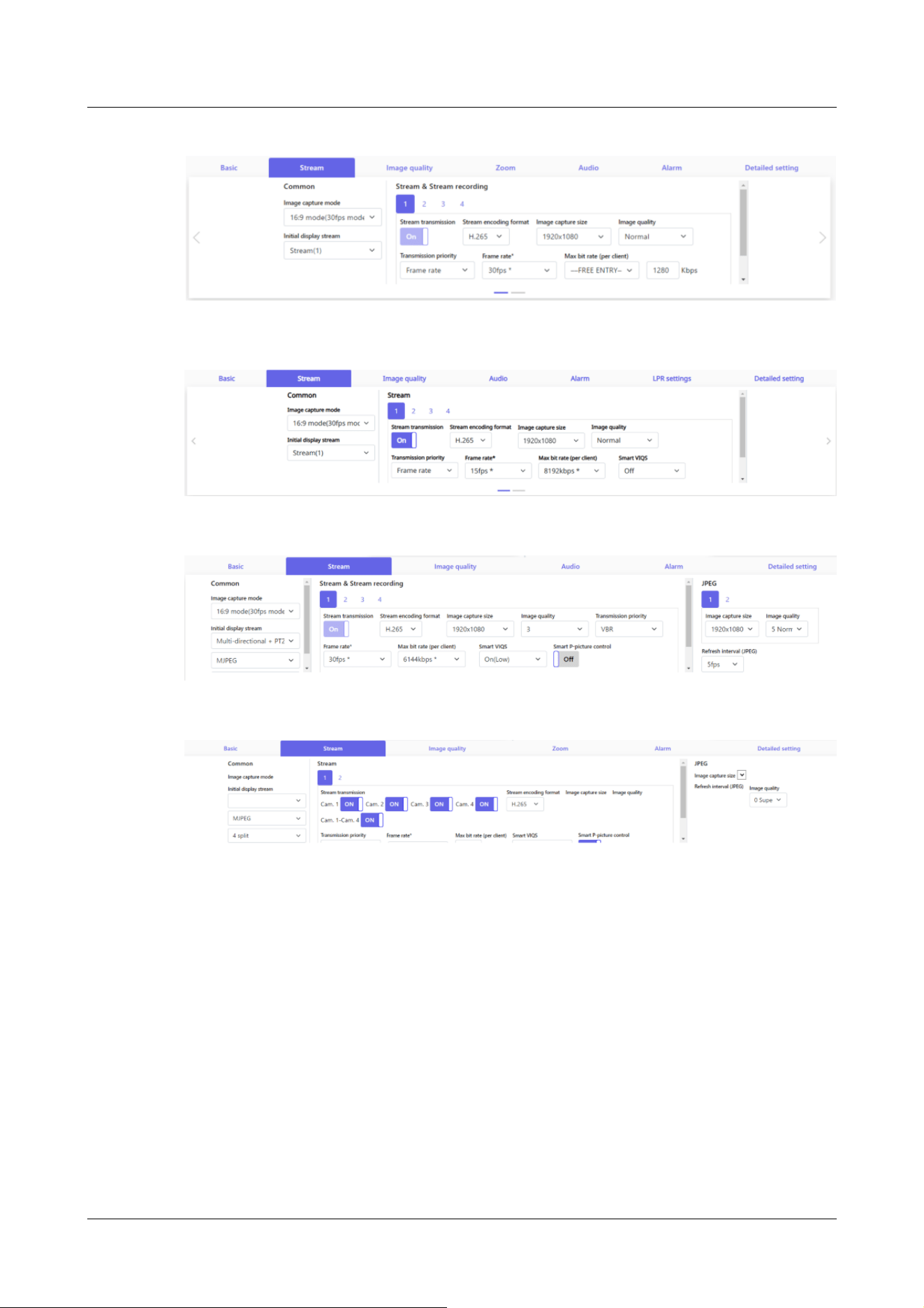
AI Outdoor IR Bullet Camera
PTZ camera
Multi-directional camera
① [Basic] tabs
[Basic] displays the tabs. On the [Basic] tab, you can set the camera titles and display
characters.
→3.2 [Basic] to perform basic settings
② [Stream] tabs
[Stream] displays the tabs. On the [Stream] tabs, you can set up imaging modes, JPEGs,
streams, etc.
→3.3 [Stream] for setting images
③ [Image quality] tabs
[Image quality] displays the tabs. In the [Image quality] tabs, you can set the image quality.
→3.4 [Image quality] for setting image quality
3 Setting
3.1 Displaying the configuration panel from the PC
157

[Note:]
・Refer to the catalog specifications for the functions installed in each model.
④ [Zoom] tabs
[Zoom] displays the tabs. On the [Zoom] tab, you can set zooming and other settings.
→3.5 [Zoom] for setting Digital zoom(EX zoom)
→3.6 [Zoom] for setting Digital zoom(EX optical zoom)
→3.7 [Zoom] for set zoom/focus
⑤ [Audio] tabs
[Audio] displays the tabs. The [Audio] tabs configure audio-related settings.
→3.8 [Audio] for setting sound
⑥ [Alarm] tabs
[Alarm] displays the tabs. The [Alarm] tabs configure the alarm settings.
→3.9 [Alarm] to set alarm
⑦ [LPR settings] tabs
[LPR settings] displays the tabs. In the [LPR settings] tabs, you can set the LPR settings.
→3.10 [LPR settings] to set LPR settings
⑧ [Detailed setting] tabs
[Detailed setting] displays the tabs. On the [Detailed setting] tabs, you can migrate to
advanced settings and set up control panels.
→3.11 [Detailed setting] for switching to advanced settings and setting related to the
displayed images
3.2 [Basic] to perform basic settings
The [Basic] tabs set the camera titles and display settings. See the [Basic] tabs on the Advanced
Basic Page for a detailed explanation of the settings and notes for settings.
→9 [Basic] for basic setup of the machine
[Basic]
Set basic items such as camera title.
・
[Camera title]
Enter the this product name. The entered name is displayed in the camera title.
3 Setting
3.2 [Basic] to perform basic settings
158

[Note:]
・[MULTI] [Image rotation] by cameras [date and time]&Set in [Characters on
Screen].
[Note:]
・[MULTI] Only the Multi-directional camera can be selected for [Camera].
・[MULTI] [Image rotation] can be selected for 2-eye Multi-directional cameras
only.
Date and time&Characters on screen
Specify the display position and size of the character string to be displayed on the screen.
・
[Camera]
Select from [Camera 1] to [Camera 4] to individually set the following items for the selected
camera.
・[Image rotation]
・[Camera title on screen display]
・[Camera title on screen(Line 1)]
・[Camera title on screen(Line 2)]
・[Camera title position]
・Date and time&In-screen text display format
・[Character size]
・ [Image rotation]
Select from [0 °(Off)], [90°] and [180 °(Upside-down)], and [270°].
・ [Camera title on screen display]
Use [On]/[Off] to set whether the strings are displayed on the images.
When set to [On], the character strings entered in [Camera title on screen] are displayed
at the position selected in [Position].
・ [Camera title on screen(Line 1)] /[Camera title on screen(Line 2)]
Enter a character string to be displayed in the image.
・ [Camera title position]
Select the position where the character string is displayed in the image.
・ [Time/date and camera title on screen - display format]
Sets the display format to either [Permeation] or [Opaque].
・ [Character size]
Select the date and time displayed in the image and the character size of the character
3 Setting
3.2 [Basic] to perform basic settings
159

[Note:]
・Refer to the catalog specifications for the functions installed in each model.
string.
[Installation position]
・
[Tilt adjustment lever position]
Select the [Tilt adjustment lever position] set when the cameras are installed.
3.3 [Stream] for setting images
The [Stream] tabs configure settings for JPEG, H.265, and H.264 images.
For a detailed explanation of the settings and notes for setting, refer to the [Image] tabs on the
image/audio pages in the detailed settings.
→10.1 [Image] to set the imaging modes
[Common]
Set the common items for JPEG and stream.
・
[Image capture mode]
Select the image to be displayed on the live image, etc.
・
[Initial display stream]
Select the image to be displayed on the live image page.
[Stream]
Select the number of the stream and set the [Stream transmission].
・
[Stream transmission]
On/Off sets whether to deliver H.265 (or H.264) images.
・
[Stream encoding format]
Select the compression method for the stream to be delivered.
・
[Image capture size]
Select the resolution of the H.265 (or H.264) image.
・
[Image quality]
Select the quality of the H.265 (or H.264) image.
・
[Transmission priority]
3 Setting
3.3 [Stream] for setting images
160

Set the stream delivery mode.
・
[Frame rate*]
Sets the frame rate.
・
[Max bit rate (per client) *]
Select the H.265 (or H.264) bit rate for one client.
・
[Auto VIQS]
Images are distributed so that the quality of images in moving places is high and the amount of
data in other places is low.
・
[Smart VIQS]
Images are distributed so that the amount of data decreases while maintaining high image
quality in areas with objects (head, people, cars and motorcycles) and low/medium/medium
image quality in other areas.
・
[Smart P-picture control]
To reduce the amount of data, control the generation of data (macroblock) as little as possible
except where there is an object (head, person, car, or motorcycle).
・
[GOP control]
The GOP control reduces the amount of data.
[JPEG]
Configure the JPEG [Image capture size] [Image quality] [Transmission interval].
・
[Image capture size]
When displaying JPEG images, select the resolution of the images to be displayed.
・
[Image quality]
Set the quality of JPEG images at each resolution.
・
[Refresh interval(JPEG)]
Select the rate at which the JPEG image is updated from the following.
3.4 [Image quality] for setting image quality
On the [Image quality] tabs, you set image quality.
For a detailed explanation of the settings and notes for setting, refer to the [Image quality] tabs on
the image/audio pages in the detailed settings.
→10.4 [Image quality] to set the image quality
[Image quality]
You can set various image quality adjustments such as brightness and sharpness level.
3 Setting
3.4 [Image quality] for setting image quality
161

[Note:]
・[MULTI] Only Multi-directional cameras can be selected for [Camera selection].
・[MULTI] This item is not displayed when [Image capture mode] is in Quad/Dual
mode.
・[MULTI] For [Common(Cam. 1-2)], [Super Dynamic], [Light control mode],
[White balance], and [Intelligent Auto] can be set only for items that have not
been developed in detail. To perform other advanced settings, select each camera.
・
[Camera selection]
Select the camera to set the image quality.
・[Common(Cam. 1-2)]: Sets the same settings for the cameras.
・[Camera 1]: Sets camera 1 image quality.
・[Camera 2]: Sets camera 2 image quality.
・[Camera 3]: Sets the image quality of camera 3.
・[Camera 4]: Sets camera 4 image quality.
・
[Brightness]
Adjust the brightness.
Move the slider bar in the [+] direction to brighten the image.
Move the slider bar in the [-] direction to darken the image.
Press [Reset] to return to the default brightness.
・
[Sharpness level]
Adjust the sharpness level (contour correction).
Moving the slider bar in the direction of [+] results in a sharp contour, and moving the slider
bar in the direction of [-] results in a soft contour.
Press [Reset] to return to the default settings.
・
[Maximum gain]
Adjust the maximum gain. When the subject's illumination becomes dark, the gain automatically
increases and the screen brightens.
Increasing the gain may increase the noise.
Move the slider bar in the [+] direction to increase the maximum gain.
Move the slider bar in the [-] direction to reduce the maximum gain.
Press [Reset] to return to the default settings.
・
[Digital noise reduction]
The digital noise reduction function automatically reduces noise at low illumination levels.
Move the slider bar in the direction of [+] to increase the effect of noise reduction. There may
be a lot of afterimages.
3 Setting
3.4 [Image quality] for setting image quality
162

[Note:]
・Refer to the catalog specifications for the functions installed in each model.
Moving the slider bar in the direction of [-] reduces the noise reduction effect. There are fewer
aftereffects.
Press [Reset] to return to the default settings.
・
[Super Dynamic]
On/Off is used to specify whether or not the super dynamic function can be activated.
・
[Light control mode]
Select the mode to control the light intensity.
・
[Maximum shutter]
The maximum exposure time adjusts the maximum storage time of the sensor.
・
[D&N]
Select the mode for switching between black and white images and color images.
・
[Intelligent Auto]
Set ON/OFF whether the intelligent auto function is enabled or not.
・
[White Light]
On/Off is used to specify whether or not the White Light function can be activated.
・
[White Light intensity]
Select from [High], [Middle], and [Low].
3.5 [Zoom] for setting Digital zoom(EX zoom)
On the [Zoom] tab, you set the angle of view of the image displayed during zooming.
For a detailed explanation of the settings and notes for setting, refer to the [Image quality] tabs on
the image/audio pages in the detailed settings.
→10.4.3 Adjust the angle of view with the Digital zoom(EX zoom)
[Zoom]
Set the field of field of field.
・
[Camera selection]
Select the camera to set EX zoom.
3 Setting
3.5 [Zoom] for setting Digital zoom(EX zoom)
163

[Note:]
・[MULTI] Only Multi-directional cameras can be selected for [Camera selection].
[Note:]
・Refer to the catalog specifications for the functions installed in each model.
・
[Extra zoom]
X1: Zoom (magnification) is 1.0 times.
Adjust the zoom factor to 1.0 times in the [Wide Angle] direction.
: Adjust the zoom factor in the [Telescope] direction.
3.6 [Zoom] for setting Digital zoom(EX optical zoom)
On the [Zoom] tab, you set the angle of view of the image displayed during zooming.
For a detailed explanation of the settings and notes for setting, refer to the [Image quality] tabs on
the image/audio pages in the detailed settings.
→10.4.4 Adjust the angle of view with the Digital zoom(Ex optical zoom)
[Zoom]
Set the field of field of field.
・
[Digital zoom(Extra optical zoom)]
X1: Zoom (magnification) is 1.0 times.
Adjust the zoom factor to 1.0 times in the [Wide Angle] direction.
: Adjust the zoom factor in the [Telescope] direction.
3.7 [Zoom] for set zoom/focus
Use Zoom and EX optical zoom to adjust the angle of view of the displayed image.
Adjust the focus by moving the lens focus to the optimal position. It can be adjusted manually or
automatically.
→10.4.5 Adjust the zoom/focus
3 Setting
3.7 [Zoom] for set zoom/focus
164

[Note:]
・Refer to the catalog specifications for the functions installed in each model.
[Zoom]
Set the field of field of field.
・
[Camera selection]
Select the camera to set zoom and focus.
・
[Zoom ratio designation]
Adjust the zoom and focus simultaneously.
Press the slider bar to zoom in or out the angle adjustment frame in the image.
When you adjust the zoom (magnification) in the "telephoto" direction, only the image
adjustment frame is reduced and you can specify the zoom (magnification) while checking the
angle of view after the zoom is executed.
When the zoom (magnification) is adjusted in the "Wide angle" direction, the image itself is
reduced or the frame for the zoom angle adjustment is enlarged. You can specify the zoom
(magnification) while checking the image size after the zoom is executed.
Adjust the angle of view adjustment frame, and click [Execute] to zoom. Then, automatically
adjust the focus to the object in the center of the window using the auto focus function.
・
[Manual zoom adjustment]
Adjust the zoom manually.
Adjust the zoom factor to 1.0 times in the [Wide Angle] direction.
X1: Zoom (magnification) is 1.0 times.
: Adjust the zoom factor in the [Telescope] direction.
・
[Manual focus adjustment]
Adjust the focus manually.
[Reset] returns focus (focus) to its default settings.
[Near]: Adjust the focus to the [Near].
[Far]: Adjust the focus to the [Far].
・
[Auto focus]
When [Execute] is clicked, the auto focus function is activated to automatically adjust the
focus to the object in the center of the window.
・
[Focusing at Day & Night switching]
Select the focus adjustment method when switching between color image and black-and-white
image from the following. For details, refer to our technical information website <Control No.
3 Setting
3.7 [Zoom] for set zoom/focus
165

[Note:]
・Refer to the catalog specifications for the functions installed in each model.
C0315>.
3.8 [Audio] for setting sound
The [Audio] tabs configure audio-related settings.
For a detailed explanation of the settings and notes for setting, refer to the [Audio] tabs on the
image/audio pages in the detailed settings.
→10.5 [Audio] for setting sound
[Audio]
Sets sound and volume items.
・
[Mic select]
Select the microphone to use when receiving audio data.
・
[Mic input volume]
Set the volume of sound input to the computer. This setting is reflected in the volume of sound
(listening) on the computer and the volume at [Audio recording].
・
[Audio transmission mode]
Set the communication mode for sending/receiving voice data between the computer and the
PC.
・
[Audio input encoding format]
Select the compression method for the earpiece sound.
・
[Audio volume control mode]
Select how to use the volume cursor of the earpiece button on the live picture page.
3.9 [Alarm] to set alarm
The [Alarm] tabs configure the alarm settings.
See the [Alarm] tabs on the alarm pages for detailed explanations of setting values and notes for
3 Setting
3.9 [Alarm] to set alarm
166

[Note:]
・Refer to the catalog specifications for the functions installed in each model.
setting values.
→14 [Alarm] to set the alarm
[Alarm]
Set terminal operation and alarm items.
・
[Terminal 1]
Set the operation of terminal 1.
・
[Terminal 2]
Set the operation of terminal 2.
・
[Terminal 3]
Set the operation of terminal 3.
・
[VMD alarm]
ON/OFF is used to specify whether or not to perform operation detection.
When set to [On], the entire area is specified in the VMD area. To specify an arbitrary action
detection area, set it on the [VMD area] tab of the alarm page of the advanced setting.
→14.5 [VMD area] for setting motion detection
The [VMD area] tabs on the advanced alarm pages are accessible from live picture links.
・
[Scene change detection (SCD) alarm]
ON/OFF is used to specify whether or not to perform undesired detection.
When set to [On], the entire area is specified in the SCD area. To specify an optional
disturbance detection area, use the [SCD area] tabs on the alarm pages in Advanced Settings.
→14.7 [SCD area] to set up undesired detection
The [SCD area] tabs on the advanced alarm pages are accessible from live picture links.
・
[Audio detection alarm]
ON/OFF is used to specify whether or not to perform sound detection.
When set to [On], all AI sounds are enabled. To configure the details of sound detection, use
the [Audio detection] tabs on the alarm pages in Advanced Settings.
→14.9 [Audio detection] for setting sound detection
The [Audio detection] tabs on the advanced alarm pages are accessible from live picture links.
・
[Impact detection alarm]
Use On/Off to set whether or not to perform impact detection.
When set to [On], impact detection is enabled.When setting the details of impact detection,
3 Setting
3.9 [Alarm] to set alarm
167

[Note:]
・The items that can be set differ depending on the function of the model.
・Refer to the catalog specifications for the functions installed in each model.
set it in the [Impact detection] tab of the alarm page of the detail setting.
→14.10 [Impact detection] for setting impact detection
The [Impact detection] tab on the Advanced Alarm page can be accessed via the link in the live
image.
・
[Casing open detection alarm]
Use On/Off to set whether or not to perform opening detection.
When set to [On], opening detection is enabled. When setting the details of opening detection,
set it in the [Casing open detection] tab of the alarm page of the detail setting.
→14.11 [Casing open detection] for setting opening detection
The [Casing open detection] tab on the Advanced Alarm page can be accessed via the link in
the live image.
・
[Alarm deactivation time]
Sets the time when the alarm is detected and the detection operation is not executed. For
example, if you set up an e-mail notification to a mobile terminal or a tablet terminal using an
alarm, this setting prevents you from sending too much e-mail.
3.10 [LPR settings] to set LPR settings
The [LPR settings] tabs configure the LPR settings.
3 Setting
3.10 [LPR settings] to set LPR settings
168
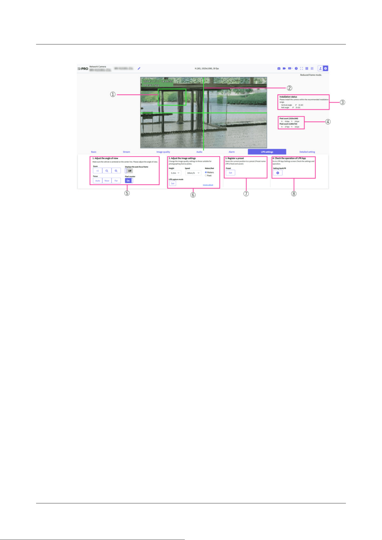
[LPR settings]
The [LPR settings] window allows you to set the image angle and image quality appropriate for
license plate identification, register presets, and check the operation of LPR app.
① [Pixel counter display frame]
A frame appears in the main-area only when [Pixel counter] is set to [On]. You can move the
displayed frame in the main area by dragging. You can also change the size of the frame when
you drag the mouse in the lower right corner.
If [Pixel counter] is set to [Off] or other tabs are displayed, the frame is not displayed.
② [Center Line]
Clicking the [LPR settings] tab. A crosshair line will be displayed in the displayed main area.
③ [Installation status]
Displays the installation status (Vertical angle and Roll angle) of the camera on the screen.
④ [Pixel count]
The number of pixels in X (horizontal width) and Y (vertical width) at 1920x1080 conversion
and the number of pixels in X (horizontal width) and Y (vertical width) at 1280x720
conversion are displayed in the frame enclosed in the [Pixel counter display frame].
⑤ [1. Adjust the angle of view]
You can adjust the angle of view when installing the camera.
Adjust the frame size so that the number of pixels in the Pixel counter frame is VaxALPR
(Vaxtor LPR MMC) is the recommended value. Adjust the angle of view so that the license
plate fits within the frame.
3 Setting
3.10 [LPR settings] to set LPR settings
169

[Note:]
・For more information about VaxALPR(Vaxtor LPR MMC), see Support for
Vaxtor Technologies.
[Note:]
・Adjust by moving the camera vertically and horizontally so that the license plate
is at the center of the angle of view. For the center of the angle of view, refer to
the center line of the crosshair displayed in the main area when clicking the [LPR
settings] tab. After setting the number plate so that it is at the center of the angle
of view, adjust the zoom magnification and focus position with the Zoom and
Focus buttons so that it fits within the frame displayed in the main area by setting
the number plate to [Pixel counter] to [On].
・
[Zoom]
:Zoom (magnification) 1.0 times.
:Adjust the zoom factor in the [Wide angle] direct
:Adjust the zoom factor in the [Telescope] direction.
・
[Focus]
[Auto]:Automatically adjust focus.
[Near]:Adjust the focus (focus) to [Near].
[Far]:Adjust the focus (focus) to [Far].
[Displays the auto focus frame]: [On] and draw a frame on the image to adjust the focus (focus)
to the frame.
・
[Pixel counter]
When set to [On], displays the Pixel counter display frame in the main area.
⑥ [2. Adjust the image settings]
Adjusts the picture quality suitable for license plate identification.
・
[Height]
Select the height of the camera from the pull-down menu.
The items in the pull-down menu change according to the selection of [Meters/feet].
When [Meters] is selected: [3.0m]/ [3.5m]/ [4.0m]/ [4.5m]/ [5.0m]/ [5.5m]/ [6.0m]/ [6.5m]/
[7.0m]/ [7.5m]/ [8.0m]/ [8.5m]/ [9.0m]/ [9.5m]/ [10.0m]
When [Feet] is selected: [10ft.]/ [12ft.]/ [14ft.]/ [16ft.]/ [18ft.]/ [20ft.]/ [22ft.]/ [24ft.]/
[26ft.]/ [28ft.]/ [30ft.]/ [32ft.]
・
[Speed]
3 Setting
3.10 [LPR settings] to set LPR settings
170

Item Set value
Maximum gain 3
DNR 128
Super Dynamic(SD) Off
Maximum shutter [1/1000]/ [1/500]/ [1/250]
*1
Intelligent Auto Off
Contrast level 200
Adjusting method Fixed focus shift(LPR)
Day & Night(IR) Auto4(LPR)
IR LED light irradiation range control [Auto]/ [Manual]
*2
IR LED light irradiation range(Manual) [1(mid + tele)]/ [2(mid)]/ [3(wide + mid)]/
[4(wide)]
*3
Select the speed of the vehicle to be photographed from the pull-down menu.
The items in the pull-down menu change according to the selection of [Meters/feet].
When [Meters] is selected: [30km/h]/ [60km/h]/ [90km/h]/ [120km/h]
When [Feet] is selected: [20mi/h]/ [40mi/h]/ [60mi/h]/ [75mi/h]
・
[Meters/feet]
You can switch between [Meters] and [Feet] by clicking the radio button.
Switch the display of the [Height] and [Speed] pull-down menus by setting [Meters/feet].
・
[LPR capture mode]
Clicking [Set] sets the image quality suitable for license plate recognition.
The following settings are changed in [LPR capture mode].
*1 Maximum shutter setting is calculated based on the Vertical angle, installation height,
vehicle speed, and zoom factor when [Set] key is clicked.
*2 For [AI Outdoor IR BulletX-8M], [Auto] is set. For [AI Outdoor IR BulletX-5M] and [AI
Outdoor IR BulletX-2M], [Manual] is set.
*3 The setting of IR LED light irradiation range(Manual) is calculated by the Vertical angle,
installation height, and maximum shutter when [Set] button is clicked. Only models whose
IR LED light irradiation range control is set to Manual are set.
・
[Image adjust]
Click this button to display the image quality adjustment menu window, where you can perform
detailed image quality adjustments.
For the setting method, refer to the following.
→10.4.1 To adjust the image quality (image quality adjustment screen)
3 Setting
3.10 [LPR settings] to set LPR settings
171

[Note:]
・[AI Outdoor IR BulletX] [Height], [Speed], [Meters/feet], and[LPR capture
mode] can only be set for the AI Outdoor IR Bullet Camera (X series).
[Note:]
・If VaxALPR(Vaxtor LPR MMC) is not installed, [4. Check the operation of LPR
App] is not displayed.
・For more information about VaxALPR(Vaxtor LPR MMC), see Support for
Vaxtor Technologies.
・[AI Outdoor IR BulletX] [4. Check the operation of LPR App] can only be set for
the AI Outdoor IR Bullet Camera (X series).
[Important]
・VaxALPR(Vaxtor LPR MMC) is a Third Party Application. Note the following
points when using Third Party Application.
Terms and Conditions on Installation of Third Party Application
You may install a third party's application ("Third Party Application")on your
i-PRO Product ("Product") and you are starting to install Third Party Application.
You agree on the following terms and conditions upon commencement of use of
Third Party Application or completion of installation thereof;
1.All rights including intellectual property rights and ownership of or relating
to Third Party Application belong to the proprietor of such Third Party
Application and are not assigned to you.
.
⑦ [3. Register a preset]
The setting information of the current position can be registered.
・
[Preset]
By clicking [Set] button. the current settings can be registered to preset position 1.
⑧ [4. Check the operation of LPR App]
You can navigate to the settings screen of the installed numberplate identification application
and check the settings and operation.
For how to install the application, refer to the following.
・
[Setting VaxALPR]
You can go to VaxALPR(Vaxtor LPR MMC) configuration screens for third-party applications.
Clicking the
button displays VaxALPR(Vaxtor LPR MMC) setting window in a separate
window.
3 Setting
3.10 [LPR settings] to set LPR settings
172

2.You may use Third Party Application only combined or connecting with
Product.
3.TO THE EXTENT ACCEPTED BY THE LAWS OF RELEVANT
JURISDICTION, i-PRO DOES NOT REPRESENT AND WARRANT ON (i)
PERFORMANCE OR BEHAVIOR OF PRODUCT RELATING TO USE
OF THIRD PARTY APPLICATION; (ii) SPECIFICATION OR QUALITY
OF THIRD PARTY APPLICATION; AND (iii) NON-INFRINGEMENT OF
INTELLCTUAL PROPERTY RIGHT OF ANY THIRD PARTY.
4.To the extent accepted by the laws of relevant jurisdiction, i-PRO gives no
indemnification for any direct or indirect damages caused by or relating to
use or installation of Third Party Application.
5.In addition to this terms and conditions, your use of Third Party Application
may be subject to other terms and conditions or limitations provided by the
proprietor of Third Party Application.
[Important]
・VaxALPR(Vaxtor LPR MMC) is a third-party application for license plate
recognition. In no event shall we be liable for any failure, damage, or damage
caused by the use of VaxALPR(Vaxtor LPR MMC).
[Note:]
・Refer to the catalog specifications for the functions installed in each model.
3.11 [Detailed setting] for switching to advanced settings and
setting related to the displayed images
Function extension software
・
[Ext. software] buttons
Displays the menu for managing the function extension software and setting the schedule.
→6 [Ext. software] for managing and scheduling advanced software
Network
・
[Network] buttons
3 Setting
3.11 [Detailed setting] for switching to advanced settings and setting related to the displayed images
173

The Network Settings menu is displayed.
→16 Networking configuration [Network]
Maintenance
・
[Maintenance] buttons
This displays menus for checking the system log, software version upgrade, status check, and
initialization of the computer settings.
→18 [Maintenance] to maintain the machine
Camera details
・
[Advanced settings page] buttons
The Advanced menu is displayed.
→5.3 Camera Advanced Menu Screen
Screen setting
・
[Color]
Select the background color of the operation panels and advanced menus from the [Light]
[Dark].
→2.3.2 About live image pages
・
[Operation panel layout]
Select the position of the control panel from [Right], [Left], and [Lower].
→2.3.2 About live image pages
3 Setting
3.11 [Detailed setting] for switching to advanced settings and setting related to the displayed images
174

[Note:]
・Refer to the catalog specifications for the functions installed in each model.
4 About network security
4.1 Security function of the unit
This machine is equipped with the following security functions.
① Restricting access by user/host authentication
Setting [On] in User Authentication/Host Authentication can restrict the users accessing
the cameras.
→15.1 [User auth.] to configure user-authentication
→15.2 [Host auth.] to configure host-authentication
② Access restrictions due to HTTP port changes
You can prevent unauthorized access, such as port scanning, by changing the HTTP port
number.
→16.1 Networking [Network]
③ Encryption of Access by HTTPS Function
By using the HTTPS function, you can encrypt the access to the camera and increase the
security of communication.
→16.2.5 Set up HTTPS
④ Falsification detection
By using the falsification detection function, you can detect falsification of data recorded on
the SD card.
→9.3 [Alteration detection] for detecting tampering
→9.4 How to set up falsification detection
⑤ SRTP communication
By using SRTP communication, the streaming data of the video data is encrypted in SSL, thus
preventing peeps in the ID/PW.
→16.2.9 Configure SRTP
⑥ IEEE 802.1X Network Access Control
4 About network security
4.1 Security function of the unit
175

[Important]
・Image data, authentication information (user name, password), alarm mail
information, DDNS server information, etc. may be leaked on the network. Take
measures such as restricting access by user authentication or encrypting access
by HTTPS.
・After the administrator has accessed the computer, be sure to close all browsers
to enhance security.
・When using the SNMP feature in SNMPv1/v2, do not configure community names
that you can easily guess. (e.g., public)
If you use a community name that you can guess easily, your computer's status
may be leaked on the network or used as a stepping stone for unauthorized access
to other devices.
[Note:]
・If you fail user authentication (authentication error) five or more times in 10
seconds from a PC with the same IP address, you will not be able to access the
machine for 30 seconds.
・You can change the conditions and period when the machine becomes inaccessible.
→15.6 [Security] to configure security
IEEE 802.1X Network Access Controls prevent unauthorized access and eavesdropping by
connecting a malicious PC to a free switching hub port in a LAN.
→15.4 [IEEE 802.1X] to configure IEEE 802.1X
4 About network security
4.1 Security function of the unit
176

[Important]
・Only users with [1. Administrator] access levels are allowed to access the Setup
menus. For details on how to set the access level, refer to the following.
→15.1 [User auth.] to configure user-authentication
5 Displaying the camera settings menu from the PC
The camera can be set in the Setup menu.
5.1 How to display
1 Displays Live image pages.
→2.3.1 View camera images
2 Displays the setting panel.
3 Click the [Detail setting] tabs.
4 Clicking [Advanced settings page] on the [Camera detailed setting] displays the Advanced
menu.
For more information on this menu, please refer to the following.
→5.3 Camera Advanced Menu Screen
5 Displaying the camera settings menu from the PC
5.1 How to display
177
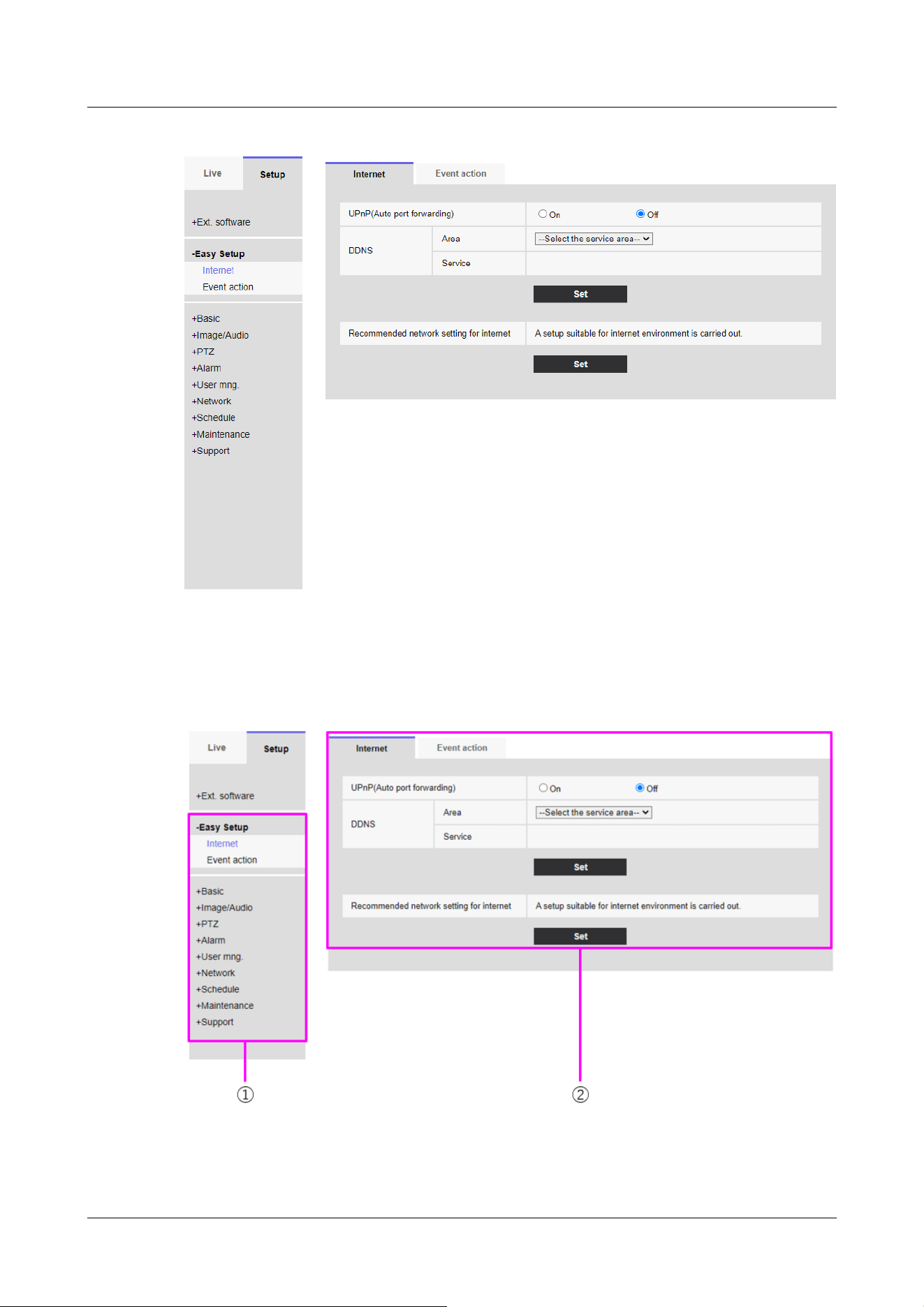
5.2 How to operate
①Menu button
5 Displaying the camera settings menu from the PC
5.2 How to operate
178
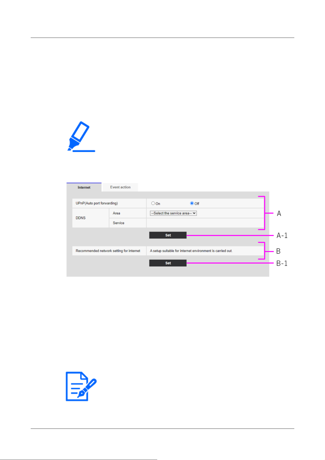
[Important]
・If there are several buttons in the [Set], [Register], and [Execute] pages, click
the [Set], [Register], and [Execute] buttons for each item.
[Note:]
・The items that can be set differ depending on the function of the model.
・Refer to the catalog specifications for the functions installed in each model.
②Configuration page
1 Click the menu button on the left side of the screen to display the setting page.
If the page consists of more than one tab, click on each tab.
2 Enter each item on the setting page.
3 Once the entry is complete, confirm the entry by clicking [Set].
<example>
When you have finished setting the items in field A, click [Set] (A-1) below field A.
If you do not press the [Set] button (A-1) at the bottom of field A, the setting will not be
confirmed.
As above, when you have finished setting the items in Box B, click [Set] (B-1) below Box B.
5.3 Camera Advanced Menu Screen
5 Displaying the camera settings menu from the PC
5.3 Camera Advanced Menu Screen
179
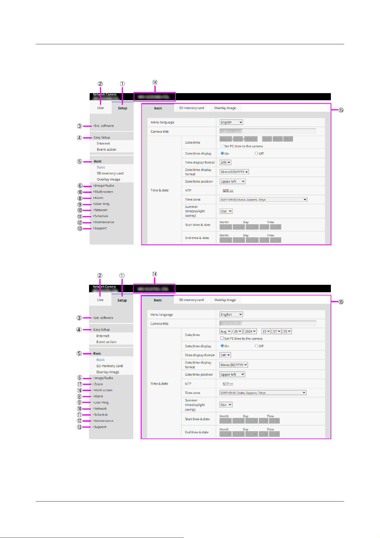
Compact Dome cameras, New X Fixed cameras
AI Outdoor IR Bullet Camera
U-series camera with edge AI
5 Displaying the camera settings menu from the PC
5.3 Camera Advanced Menu Screen
180
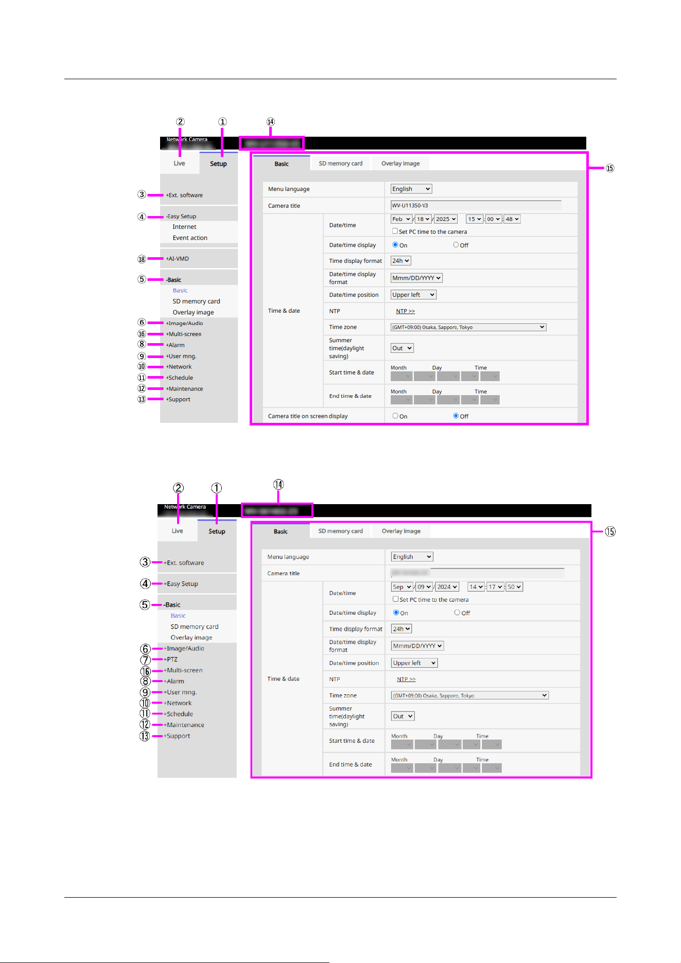
PTZ camera
Multi-directional camera
5 Displaying the camera settings menu from the PC
5.3 Camera Advanced Menu Screen
181
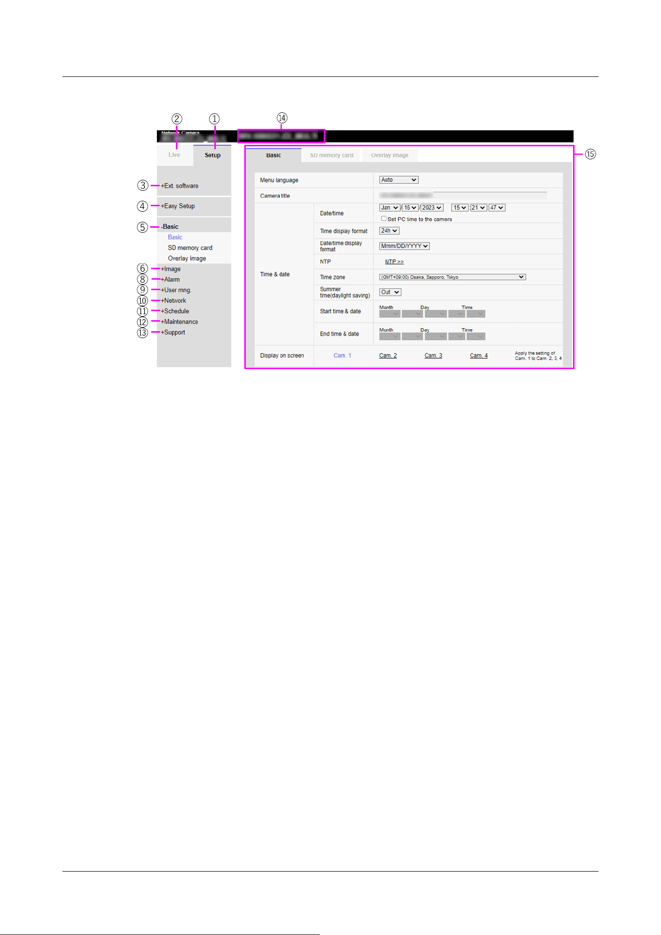
① [Setup] buttons
Indicates the setup menu.
② [Live] buttons
Live image pages are displayed.
③ [Ext. software] buttons
You can manage the function extension software and set schedules. When the function
extension software is installed, a link to the screen is displayed.
→6 [Ext. software] for managing and scheduling advanced software
④ [Easy Setup] buttons
Displays the easy setting page. On the easy setting page, the event operation such as
Internet disclosure setting, alarm setting and alarm linkage operation are set.
→7 [Easy Setup] to use easy setting
⑤ [Basic] buttons
Displays the basic page. Basic pages set basic settings such as date and time, camera title,
and information about the SD Memory Card.
→9 [Basic] for basic setup of the machine
⑥ [Image/Audio] buttons
Video/audio pages are displayed. Image/Audio pages configure camera settings such as
image quality and resolution for JPEG/H.265/H.264 images.
→10 [Image/Audio] for setting images and sound files
⑦ [PTZ] buttons
Displays the PTZ page. On the PTZ page, settings are made for the home position and
camera operations such as self-return.
5 Displaying the camera settings menu from the PC
5.3 Camera Advanced Menu Screen
182

→11 Set PTZ
⑧ [Alarm] buttons
Alarm page is displayed. On the alarm page, the alarm operation and VMD area are set, the
SCD area is set, the sound detection alarm is set, the impact detection alarm is set, the
opening detection alarm is set, and the alarm notification is set.
→14 [Alarm] to set the alarm
⑨ [User mng.] buttons
Displays the User Administration page. The User Management page is used to register
authentication and configure data encryption to restrict users and PCs accessing the computer.
→15 [User mng.] to set authentication
⑩ [Network] buttons
Displays the network page. The network pages configure the network settings for your
computer and the settings for DDNS (Dynamic DNS), SNMP (Simple Network Management
Protocol), FTP/SFTP, NTP servers, UPnP, HTTPS, Qos, SRTP, MQTT and LLDP.
→16 Networking configuration [Network]
⑪ [Schedule] buttons
Schedule page is displayed. In the Schedule page, the schedule is set for operation detection
permission, disturbance detection permission, sound detection permission, impact detection
permission, opening detection permission, etc.
→17 [Schedule] for scheduling
⑫ [Maintenance] buttons
Displays the maintenance page. On the Maintenance page, you can check the system log,
upgrade the software version, check the status, and initialize the settings of the computer.
→18 [Maintenance] to maintain the machine
⑬ [Support] buttons
The Support page is displayed. The support pages show how to display our support websites.
→19 Viewing Our Support Website [Support]
⑭ [Camera title]
Displays the currently set camera title.
⑮ [Settings page]
Displays the page of each setting menu. Depending on the menu, some pages may have more
than one tab. The lower part of the setting page is omitted.
⑯ [Multi-screen] buttons
Multi-screen page is displayed. on the Multi-screen page, the cameras from which images are
to be displayed on a multi-screen can be registered.
⑰ [Zoom] buttons
Zoom page is displayed. On the Zoom page, Zoom/Focus, Cam. Function, and Position is
5 Displaying the camera settings menu from the PC
5.3 Camera Advanced Menu Screen
183


[Note:]
・The items that can be set differ depending on the function of the model.
・Refer to the catalog specifications for the functions installed in each model.
・If the imaging modes are [16:9 mode(60fps mode)]/[16:9 mode(50fps mode)]/[4:3
mode(15fps mode)]/[4:3 mode(12.5fps mode)], the function extension software
cannot be used. The operation schedule of the function extension software during
installation is also deleted.
・Depending on the type of extension software, it may be limited to up to 7.5 fps in
15 fps mode, up to 6.25 fps in 12.5 fps mode, up to 15 fps in 30 fps mode, and up
to 12.5 fps in 25 fps mode.
・[New X Fixed][AI Outdoor IR BulletX]There is a limit to the combined use of
Extension software that can be used concurrently.
Extension software pairing is available on the support website.(Control No.:C0103)
For use in Japan:
https://i-pro.com/products_and_solutions/ja/surveillance/learning-and-
support/knowledge-base/technical-information
For use outside Japan:
https://i-pro.com/global/en/surveillance/training-support/support/technical-
information
6 [Ext. software] for managing and scheduling
advanced software
The function extension software page manages the function extension software and sets the
operation schedule. The Enhanced Software page consists of the [Software mng.], [Operation
sched.], and [Control log] tabs.
6.1 [Software mng.] for installing, uninstalling, and upgrading
function extension software
On the Extension software pages, select the [Software mng.] tabs. Please refer to the following
instructions for how to display and operate the Advanced menu.
6 [Ext. software] for managing and scheduling advanced software
6.1 [Software mng.] for installing, uninstalling, and upgrading function extension software
185
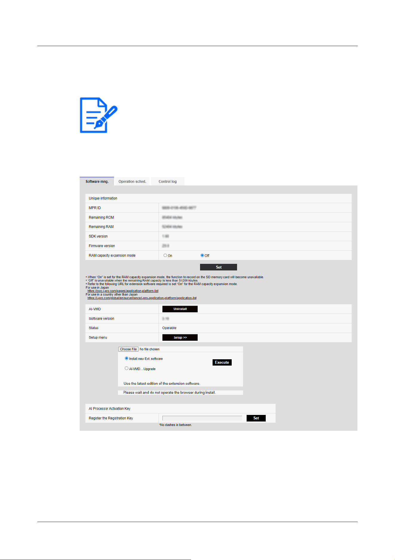
[Note:]
・The factors displayed differ depending on the function of the model.
・Refer to the catalog specifications for the functions installed in each model.
→5.1 How to display
→5.2 How to operate
Rapid PTZ Cameras, Multi-directional + PTZ (PTZ part), Compact Dome cameras, Corner
cameras, AI Outdoor IR Bullet Camera (S series), U-series camera with edge AI
Aero PTZ cameras
6 [Ext. software] for managing and scheduling advanced software
6.1 [Software mng.] for installing, uninstalling, and upgrading function extension software
186
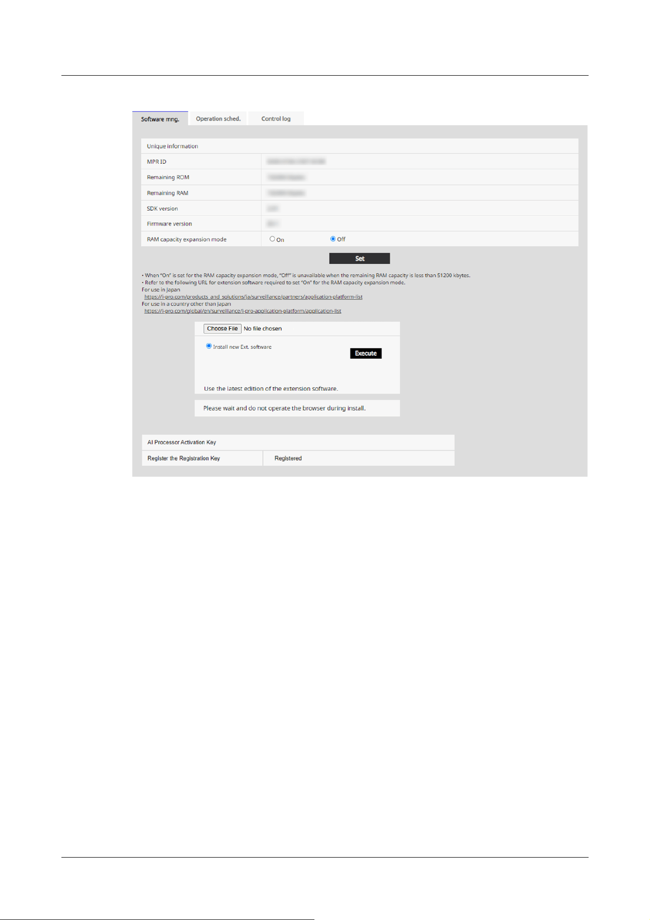
New X fixed cameras, AI Outdoor IR Bullet Camera (X series)
6 [Ext. software] for managing and scheduling advanced software
6.1 [Software mng.] for installing, uninstalling, and upgrading function extension software
187
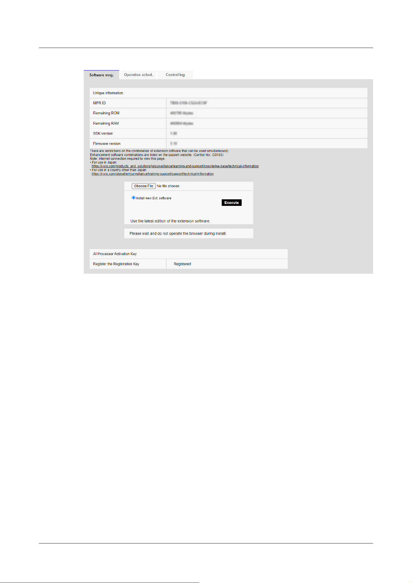
Multi-directional camera
6 [Ext. software] for managing and scheduling advanced software
6.1 [Software mng.] for installing, uninstalling, and upgrading function extension software
188
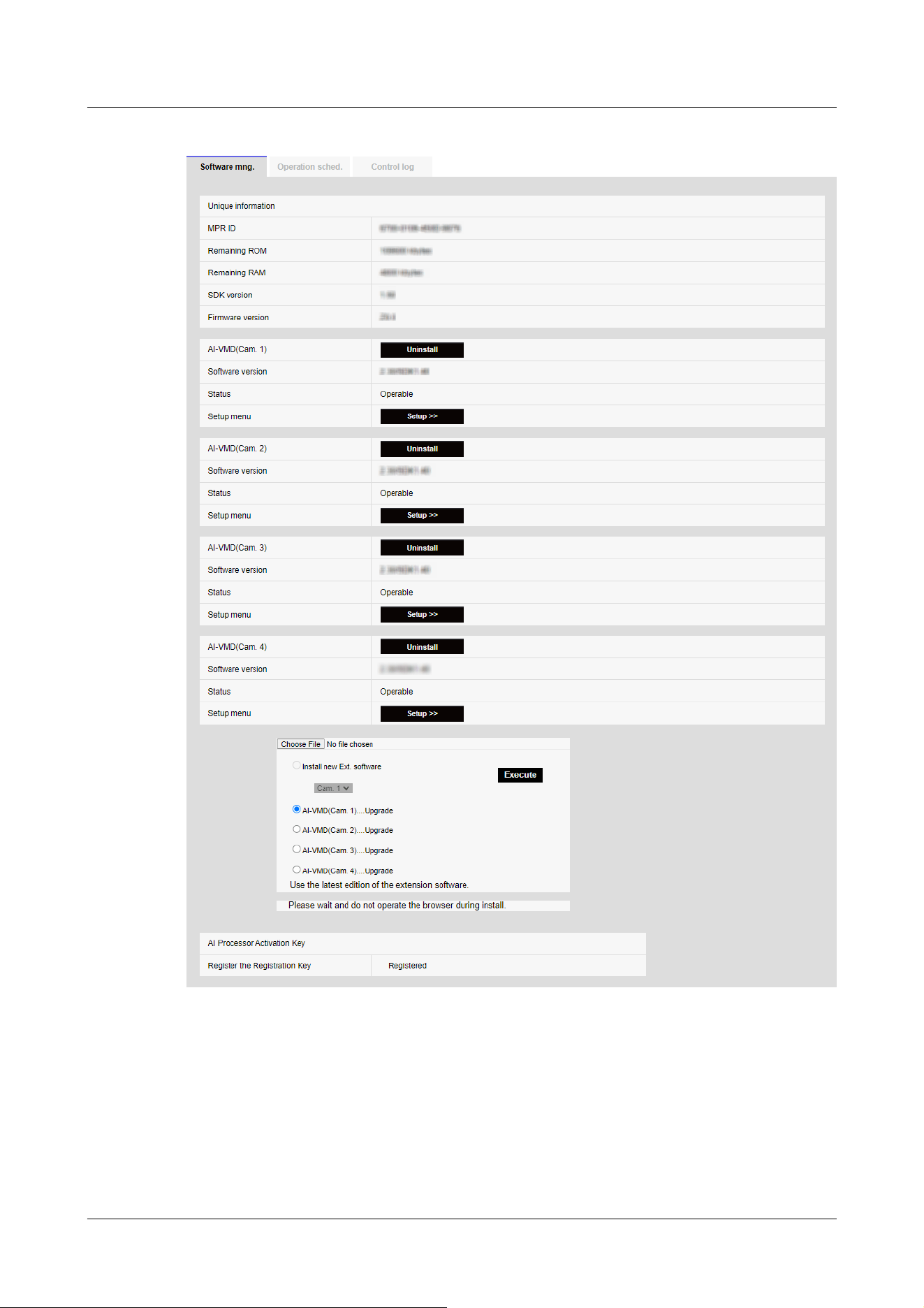
Install the function extension software
1 Save the function extension software to be installed on the PC.
6 [Ext. software] for managing and scheduling advanced software
6.1 [Software mng.] for installing, uninstalling, and upgrading function extension software
189

[Important]
・Check the [Remaining ROM] [Remaining RAM].
If there is insufficient space required to install the function extension software,
uninstall the installed function extension software.
See [Uninstall] for uninstallation.
[Note:]
・[MULTI] [Camera selection] can be selected only for Multi-directional cameras.
[Important]
・Do not use spaces or double-byte characters in the name of the destination
directory.
・Use the specified file (ext file) for Extension software.
・Do not turn off the camera during installation.
・Do not perform any operation during installation until the installation is completed.
・Extension software is installed only on the selected cameras.
・[MULTI] If Image capture mode is switched to Quad/Dual mode or from
Quad/Dual mode to another mode, all Extension software is uninstalled.
Re-install if necessary.
2 Specify the [Ext. software] by clicking [Select Files].
3 Use [Camera selection] to select the cameras where you want to install Extension software.
When Quad/Dual mode is selected, [Camera selection] items are not displayed.
4 Make sure that [Install new Ext. software] is selected and press [Execute]. [Ext. software] is
installed. When the installation is completed, the name of the function extension software
installed on the [Software mng.] window is added.
Software Management Screen
When the function extension software is installed, the camera-specific data and the registration
status of the function extension software are displayed. The following operations can be performed
on this screen.
・Uninstalling the function extension software
・Display of the detailed registration status screen
・Display of the setting screen of the function extension software
・Update of the function extension software
6 [Ext. software] for managing and scheduling advanced software
6.1 [Software mng.] for installing, uninstalling, and upgrading function extension software
190

[Note:]
•Refer to the catalog specifications for the maximum number of software extensions
that can be installed.
・For the functional extension software we sell and provide, please refer to our
technical information website<Control No. C0103>.
Model name ROM capacity RAM capacity
Multi-directional cameras 150MB 200MB
Rapid PTZ Camera(X/S Series, Image capture
size: 2MP), Multi-directional + PTZ (PTZ part),
Aero PTZ cameras (Image capture size: 2MP)
and Compact Dome cameras (X/S series,
Image capture size: 2MP), U-series camera with
edge AI(Image capture size: 2MP), U-series
camera with edge AI(Image capture size: 8MP)
100MB 100MB
Rapid PTZ cameras (X/S series, Image capture
size: 8M (4K)), Rapid PTZ Camera(X/S Series,
Image capture size: 6MP), Indoor PTZ cameras,
Aero PTZ cameras (Image capture size: 8M
(4K)), Corner cameras and AI Outdoor IR Bullet
Camera (S series)
150MB 250MB
Camera-specific data
[MPR ID]
This ID is required to issue the license cancellation key number of the function extension
software. The device has a unique device ID.
[Remaining ROM]
Displays the ROM capacity for the function extension software remaining in the camera. If the
function extension software to be installed requires more than the ROM capacity shown here, it
cannot be installed.
[Remaining RAM]
Displays the RAM capacity for the function extension software remaining in the camera. If the
function extension software to be installed requires more RAM capacity than shown here, it
cannot be installed.
The ROM capacity and RAM capacity depend on the model you use.
6 [Ext. software] for managing and scheduling advanced software
6.1 [Software mng.] for installing, uninstalling, and upgrading function extension software
191

Compact Dome cameras (X/S series, Image
capture size: 4MP), U-series camera with edge
AI(Image capture size: 5MP)
100MB 50MB
New X Fixed cameras, AI Outdoor IR Bullet
Camera (X series)
6GB 1024MB
[Note:]
・[RAM capacity expansion mode] can be selected only for models with RAM
capacity extension. Refer to this page for the models equipped with RAM capacity
extension function.
・When [RAM capacity expansion mode] is set to [On], the recording function of
the this product function on the SD Memory Card is disabled.
・If [Remaining RAM] shows negative values, uninstall Extension software or set
[RAM capacity expansion mode] to [On].
・Clicking [Set] restarts this product. After restarting, the product cannot be
operated for about two minutes as it was when the power was turned on.
・To find out if you need to set [RAM capacity expansion mode] to [On], contact
your Extension software developer.
[Note:]
・[MULTI] Only the Multi-directional camera displays the camera number.
[SDK version]
This displays the version information of the SDK installed in the camera. If the function extension
software to be installed requires more than the version number displayed here, the function
extension software may not work properly.
[Firmware version]
The camera software version information is displayed.
[RAM capacity expansion mode]
Use [On]/[Off] to set whether to expand the RAM capacity.
Extension software
[Function Extension Software Name]
The installed function extension software is displayed in the list. If the camera is installed
separately, it is displayed as [Name of Function Extension Software (Camera Number)].
6 [Ext. software] for managing and scheduling advanced software
6.1 [Software mng.] for installing, uninstalling, and upgrading function extension software
192

[Note:]
・If the function extension software does not include the SDK version information,
the SDK version information is not displayed.
[Note:]
・[MULTI] Only a Multi-directional camera can be installed.
[Uninstall] buttons
You can uninstall the installed function extension software.
[Software version]
When function extension software is installed, the version information of the installed function
extension software and the version information of the SDK incorporated in the function extension
software are displayed. If the version number of the SDK included in the camera is less than the
version number required by the function extension software, the function extension software may
not work properly.
[Status]
Displays the installation status of the function extension software. When [Operable] is displayed,
it indicates that the installed function extension software is ready for operation.
[Setup] buttons
When the function extension software has its own screen, such as the setting screen, the screen
can be displayed.
Install new extended software
Select this to install the new function extension software. Select the camera to be installed and the
function extension software to be installed.
Upgrade the version
Select the function extension software that is already installed. You can upgrade the function
extension software by clicking [Execute].
AI processor deactivation license
You can install and use the application software released from other companies using the AI
processor on your computer.
About Managing Extension software with Platform Expansion Modules
6 [Ext. software] for managing and scheduling advanced software
6.1 [Software mng.] for installing, uninstalling, and upgrading function extension software
193

[Note:]
・[New X Fixed-8M][New X Fixed-6M][AI Outdoor IR BulletX-8M] When
managed from a cloud or other server, 30fps mode is limited to the maximum
12.5fps at the maximum 15fps, 25fps mode, regardless of the configured frame
rate.
・[New X Fixed][AI Outdoor IR BulletX] When managed from a cloud or other
server, all Extension software installed on the camcorder will be stopped.
Combined with a service for a particular service provider, Extension software can be managed on a
cloud or other server.
For details, contact your service provider.
To develop Extension software for these services, see the portal site (https://dev-partner.i-pro.
com/). An account is required for browsing.
6.2 [Operation sched.] for scheduling extended software
On the Extension software pages, select the [Operation schedule] tabs. Refer to the table below
for how to display and operate the setting menu.
→5.1 How to display
→5.2 How to operate
6 [Ext. software] for managing and scheduling advanced software
6.2 [Operation sched.] for scheduling extended software
194
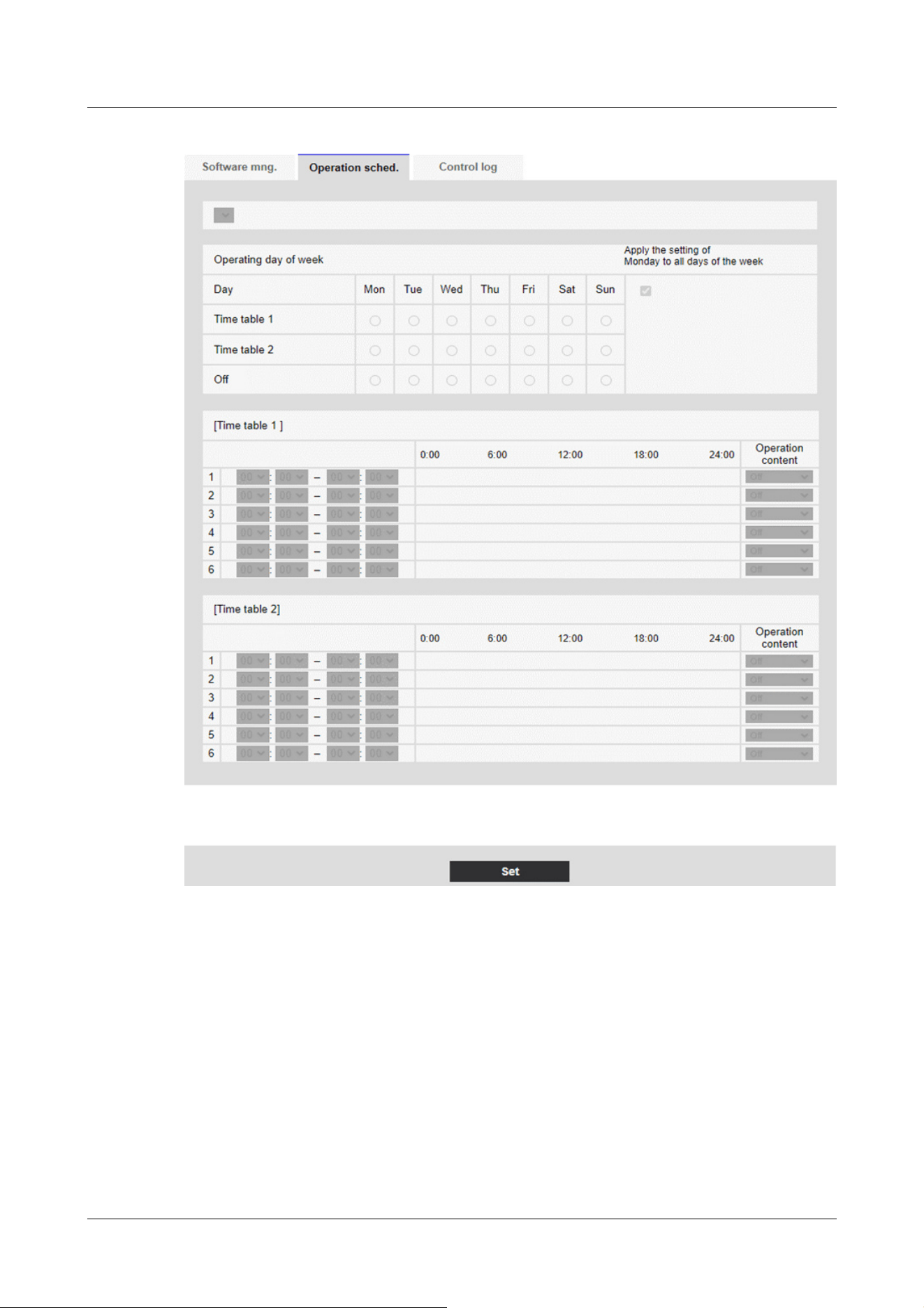
Select the function extension software to set the operation schedule.
[Operating day of week]
Select [Time table 1] [Time table 2] [Off] for each day of the week.
[Apply the setting of Monday to all days of the week]
When Box is enabled and [Set] is pressed, the setting of Monday is reflected in all days of the
week.
6 [Ext. software] for managing and scheduling advanced software
6.2 [Operation sched.] for scheduling extended software
195
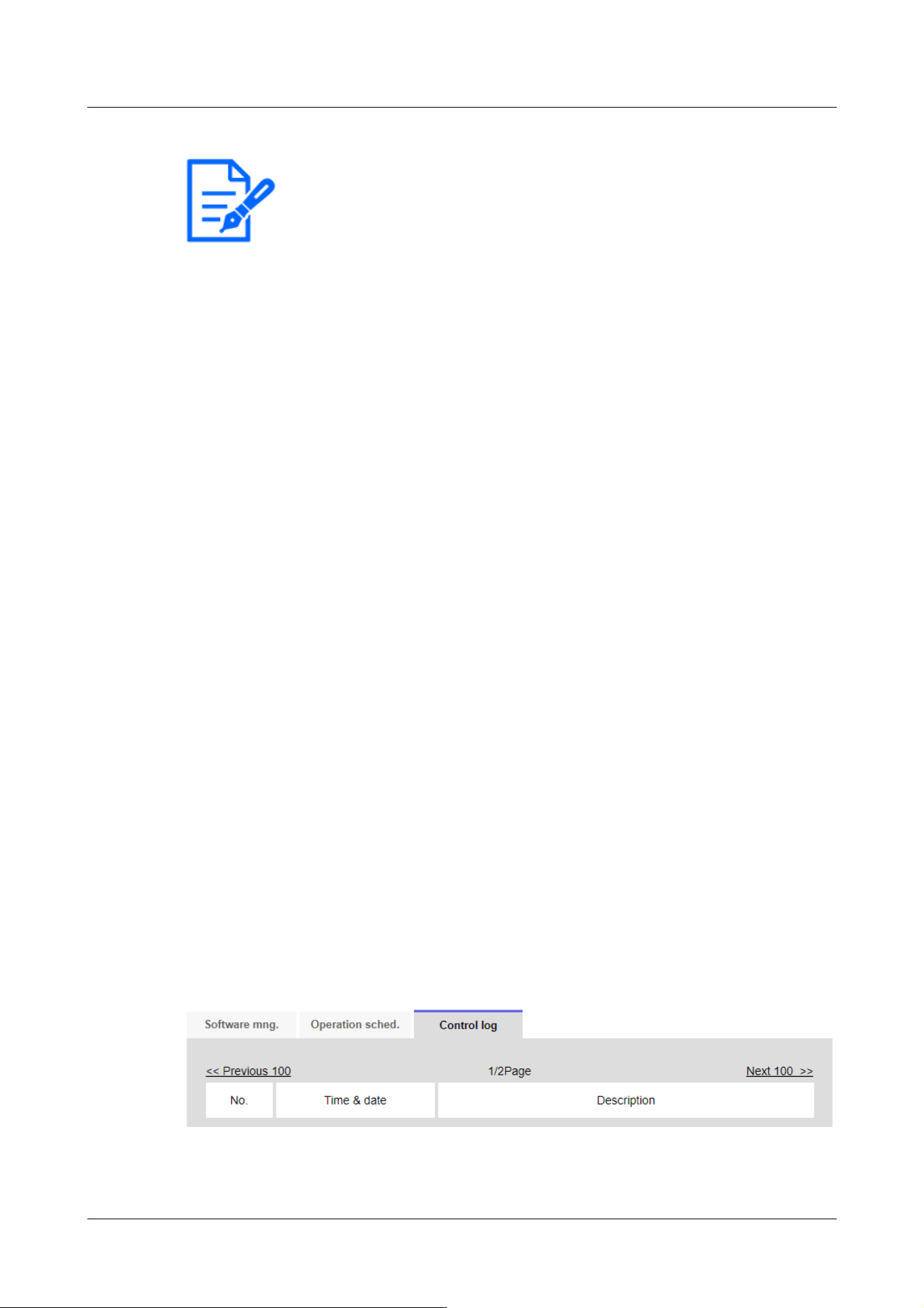
[Note:]
・[New X Fixed][AI Outdoor IR BulletX][Apply the setting of Monday to all days of
the week] can be set for New X Fixed cameras or AI Outdoor IR Bullet Camera (X
series).
[Time table 1] [Time table 2]
To specify the time, click [▼] to set the time. 24-hour setting is available for [00:00] to [00:00].
You can configure [On]/[Off] in [Operation content].
How to set the schedule
1 From the list of function extension software, select the software for which the operation
schedule is to be set.
2 In the [Operating day of week], select the day of the week and the timetable that you want to
schedule.
3 In [Time table 1] [Time table 2], specify the time zone to be operated.
Specify [00:00] to [00:00] for 24-hour operation.
4 When you are finished, press [Set].
6.3 [Control log] to check the [Control log] of the function
extension software
Displays the administration logs for Extension software. Refer to the table below for how to display
and operate the setting menu.
→5.1 How to display
→5.2 How to operate
Up to 200 management logs can be saved in the internal memory of the computer.
If the maximum number of management logs that can be saved is exceeded, the log is overwritten
from the old log.
100 management logs are displayed and saved even if the camera is turned off.
[Next 100 items>>]
6 [Ext. software] for managing and scheduling advanced software
6.3 [Control log] to check the [Control log] of the function extension software
196

Click to display the following 100 entries in the management log list that you are viewing.
[Page number display]
The currently open page is displayed in the form [Page/Total Page].
[<<Previous 100 items]
Click to display 100 items in front of the displayed management log list.
[No]
The serial number in the control log is displayed.
[Time & date]
The date and time when the log occurred is displayed.
[Description]
The contents of the management log are displayed.
For the contents of each control log, please refer to our technical information website.<Control
number: C0317>
6 [Ext. software] for managing and scheduling advanced software
6.3 [Control log] to check the [Control log] of the function extension software
197

[Note:]
・The items that can be set differ depending on the function of the model.
・Refer to the catalog specifications for the functions installed in each model.
[Note:]
・Dual mode is not supported.
・For how to adjust the camera orientation and angle, refer to the "Operation
Manual Installation".
・To automatically adjust the camera, set the vertical (TILT) angle of the camera
to 80 degrees.
7 [Easy Setup] to use easy setting
The following settings can be made on the easy setting page.
・Publish camera images on the Internet
・Sets event operation such as recording to SD Memory Card by schedule/alarm.
The easy configuration pages consist of the [Easy installation], [Internet], and [Event action]
tabs.
7.1 [Easy installation] where easy installation is performed
When the [Easy installation] tabs on the easy setting pages are clicked, the instructions for
setting the cameras are displayed.
1 Select the method in which the camera is installed.
7 [Easy Setup] to use easy setting
7.1 [Easy installation] where easy installation is performed
198
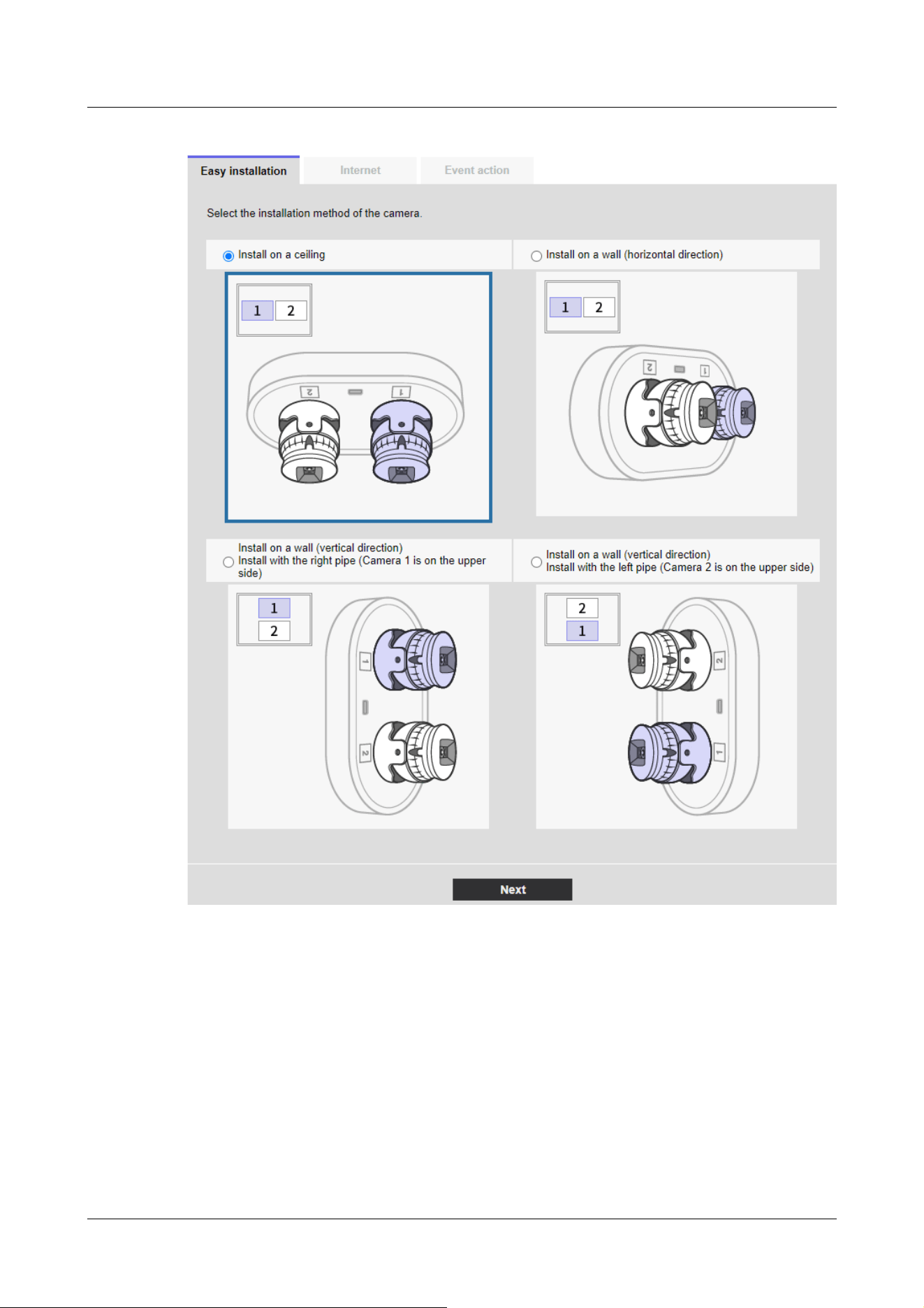
[Install on a ceiling]:
Select this when the camera is placed on the ceiling.
[Install on a wall (horizontal direction)]:
Select this when the camera is placed horizontally on the wall.
[Install on a wall (vertical direction) Install with the right pipe (Camera 1 is on the upper side)]:
Select this if the camera is installed vertically on a wall with Camera 1 facing up.
[Install on a wall (vertical direction) Install with the left pipe (Camera 2 is on the upper side)]:
Select this if the camera is installed vertically on a wall with Camera 2 facing up.
[Next]Button:
7 [Easy Setup] to use easy setting
7.1 [Easy installation] where easy installation is performed
199
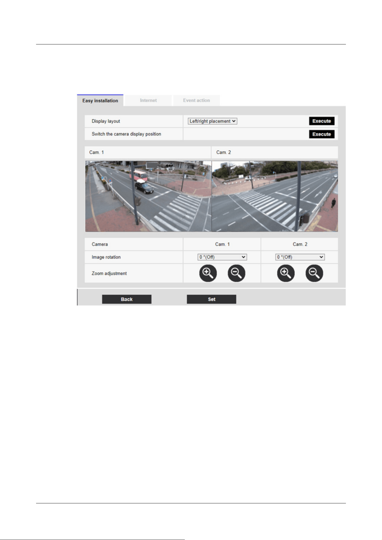
Go to the next display.
2 Check the actual display. Fine-tune the screen as required.
[Display Layout]:
The image display position can be specified.
[Left/right placement]: The screen will be left-to-right.
[Up/down placement]: The screen is positioned up and down.
Press [Execute] to refresh the window in the selected alignment.
[Switch the camera display position]:
Press [Execute] to change the displayed window.
[Image rotation]:
Rotate the displayed image.
[Zoom adjustment]:
Zoom is adjusted.
[Back]Button:
Go back to a previous screen.
[Set]Button:
7 [Easy Setup] to use easy setting
7.1 [Easy installation] where easy installation is performed
200

[Note:]
・Automatic port forwarding may change the port number. If this is changed, the
port number of the camera registered on the PC or recorder must be changed.
・The UPnP feature can be used to connect a camera to an IPv4 network. IPv6 is
not supported.
・To verify that auto-port forwarding has been configured correctly, click on the
[Status] tab on the Maintenance page and make sure that the [UPnP] status is
[On].
→18.3 [Status] for checking the status
If [On] is not displayed, please read [Cannot access cameras from internet] in
"Trouble!?"
→20.2 Trouble!?
・If you change the [UPnP(Auto port forwarding)] settings, the [UPnP] on the
[Advanced] tabs of the network pages will also change.
・If the live screen or configuration screen is not displayed correctly, such as when
replacing the routers to be used, set [UPnP(Auto port forwarding)] to [Off] once
and then set it to [On] again.
Confirms made selections.
7.2 [Internet] to set up an Internet-based disclosure system
Click the [Internet] tab for easy setting. Refer to the table below for how to display and operate
the setting menu.
→5.1 How to display
→5.2 How to operate
This is to configure the UPnP (Automatic Port Forwarding), DDNS, and Internet Recommendation
settings that are required to publish the camera on the Internet.
[UPnP(Auto port forwarding)]
You can configure [On]/[Off] to use the router's port forwarding capability.
To use the Automatic Port Forwarding feature, the router you use must be UPnP-enabled and
UPnP enabled.
[Area]
Select the region where the camera is installed.
7 [Easy Setup] to use easy setting
7.2 [Internet] to set up an Internet-based disclosure system
201

[Note:]
・Select [Japan] when using cameras in Japan. The [Viewnetcam.com] services
displayed when [Global] is selected are not accessible from within Japan.
・[Corner][Indoor PTZ][Aero PTZ] [Viewnetcam.com] servicedoes not appear even
if you select [Global].
[Note:]
・If you change the [DDNS] settings, the [DDNS] on the [Advanced] tabs of the
network pages will also change.
[Global]/[Japan]
[Service]
Select [Viewnetcam.com]/[Off] to use the [Viewnetcam.com] services in the DDNS. After you set
up the Net, click [Go to MIEMASUNET Registration page] to open the Register [Viewnetcam.
com] Services window in the new window. After that, proceed with the registration according to
the screen.
For more information, see [With [Viewnetcam.com] services] or the [Viewnetcam.com] website
(http://www.viewnetcam.com/).
→16.4.1 With [Viewnetcam.com] services
[Recommended network setting for internet]
Set the recommended settings for publishing the camera on the Internet. When [Set] is clicked,
the dialog box displays the changes in the settings for the following settings: Click OK after
checking.
Compact Dome cameras (X/S series, Image capture size: 4MP)
[Image] tabs for video and audio pages
・[JPEG(1)]
[Image capture size]:QVGA/ 320x180
・[Stream(1)] ・ [Stream(2)] ・ [Stream(3)]
[Delivery mode]: best effort delivery
[Frame rate]: 30 fps
[Max bit rate (per client) *] :1024 kbps
・[Stream(1)]
[Image capture size]:2560x1920/2560x1440
・[Stream(2)]
7 [Easy Setup] to use easy setting
7.2 [Internet] to set up an Internet-based disclosure system
202

[Image capture size] :VGA/ 640x360
・[Stream(3)]
[Image capture size] :VGA/ 640x360
[Network] tabs on network pages
・[IPv6/v4 Common]
[Maximum RTP packet size]: Limited (1280 bytes)
[HTTP max segment size(MSS)]: Restricted (1280 bytes)
Compact Dome cameras (X/S series, Image capture size: 2MP), New X Fixed Cameras(Image
capture size: 2MP),
AI Outdoor IR Bullet Camera (X series, Image capture size: 2MP)
[Image] tabs for video and audio pages
・[JPEG(1)]
[Image capture size]:QVGA/ 320x180
・[JPEG(2)]
[Image capture size]:VGA/ 640x360
・[Stream(1)]
[Delivery mode]: best effort delivery
[Frame rate]: When [Image capture mode] is [4:3 mode(30fps mode)]/ [16:9 mode(30fps
mode)]: 30fps
When [Image capture mode] is [4:3 mode(25fps mode)]/ [16:9 mode(25fps
mode)]: 25fps
When [Image capture mode] is [16:9 mode(60fps mode)]: 60fps fixed
When [Image capture mode] is [16:9 mode(50fps mode)]: 50fps fixed
[Max bit rate (per client) *] :1024 kbps
・[Stream(2)] ・ [Stream(3)] ・ [Stream(4)]
[Delivery mode]: best effort delivery
[Frame rate]: When [Image capture mode] is [4:3 mode(30fps mode)]/ [16:9 mode(30fps
mode)]: 30fps
When [Image capture mode] is [4:3 mode(25fps mode)]/ [16:9 mode(25fps
mode)]: 25fps
When [Image capture mode] is [16:9 mode(60fps mode)]: 10fps
When [Image capture mode] is [16:9 mode(50fps mode)]: 8.3fps
[Max bit rate (per client) *] :1024 kbps
・[Stream(1)]
[Image capture size]:1280x960/ 1280x720
7 [Easy Setup] to use easy setting
7.2 [Internet] to set up an Internet-based disclosure system
203

・[Stream(2)]
[Image capture size] :VGA/ 640x360
・[Stream(3)]
[Image capture size] :VGA/ 640x360
・[Stream(4)]
[Image capture size] :QVGA/ 320x180
[Network] tabs on network pages
・[IPv6/v4 Common]
[Maximum RTP packet size]: Limited (1280 bytes)
[HTTP max segment size(MSS)]: Restricted (1280 bytes)
Compact Dome cameras (U series, Image capture size: 4MP)
[Image] tabs for video and audio pages
・[JPEG(1)]
[Image capture size]:QVGA/ 320x180 (When [Image capture mode] is [16:9(30/ 25fps)
2688x1520] mode: 640x360)
・[Stream(1)]
[Delivery mode]: best effort delivery
[Frame rate]: When [Image capture mode] is [4:3 mode(30fps mode)]/ [16:9 mode(30fps
mode)][16:9 mode(2688x1520 30fps mode)]: 30fps
When [Image capture mode] is [4:3 mode(25fps mode)]/ [16:9 mode(25fps
mode)][16:9 mode(2688x1520 25fps mode)]: 25fps
When [Image capture mode] is [4:3 mode(15fps mode)]: 15fps
When [Image capture mode] is [4:3 mode(12.5fps mode)]: 12.5fps
[Max bit rate (per client) *] :1024 kbps
・[Stream(2)] ・ [Stream(3)]
[Delivery mode]: best effort delivery
[Frame rate]: When [Image capture mode] is [4:3 mode(30fps mode)]/ [16:9 mode(30fps
mode)]: 30fps
When [Image capture mode] is [4:3 mode(25fps mode)]/ [16:9 mode(25fps
mode)]: 25fps
When [Image capture mode] is [4:3 mode(15fps mode)]: 15fps
When [Image capture mode] is [4:3 mode(12.5fps mode)]: 12.5fps
When [Image capture mode] is [16:9 mode(2688x1520 30fps mode)]: Off
When [Image capture mode] is [16:9 mode(2688x1520 25fps mode)]: Off
[Max bit rate (per client) *] :1024 kbps
7 [Easy Setup] to use easy setting
7.2 [Internet] to set up an Internet-based disclosure system
204

・[Stream(1)]
[Image capture size]:1280x960 (When [Image capture mode] is [4:3(15/ 12.5fps)] mode:
2048x1536)/ 1920x1080
・[Stream(2)]
[Image capture size] :VGA/ 640x360
・[Stream(3)]
[Image capture size] :QVGA/ 320x180
[Network] tabs on network pages
・[IPv6/v4 Common]
[Maximum RTP packet size]: Limited (1280 bytes)
[HTTP max segment size(MSS)]: Restricted (1280 bytes)
Compact Dome cameras (U series, Image capture size: 2MP)
[Image] tabs for video and audio pages
・[JPEG(1)]
[Image capture size]:QVGA/ 320x180
・[Stream(1)] ・ [Stream(2)]
[Delivery mode]: best effort delivery
[Frame rate]: When [Image capture mode] is [4:3 mode(30fps mode)]/ [16:9 mode(30fps
mode)]: 30fps
When [Image capture mode] is [4:3 mode(25fps mode)]/ [16:9 mode(25fps
mode)]: 25fps
[Max bit rate (per client) *] :1024 kbps
・[Stream(3)] ・ [Stream(4)]
[Delivery mode]: best effort delivery
[Frame rate]: When [Image capture mode] is [4:3 mode(30fps mode)]: 30fps
When [Image capture mode] is [4:3 mode(25fps mode)]: 25fps
When [Image capture mode] is [16:9 mode(30fps mode)]: 5fps
When [Image capture mode] is [16:9 mode(25fps mode)]: 6.25fps
[Max bit rate (per client) *] :1024 kbps
・[Stream(1)]
[Image capture size]:1280x960/ 1280x720
・[Stream(2)]
[Image capture size] :VGA/ 640x360
・[Stream(3)]
[Image capture size] :QVGA/ 320x180
7 [Easy Setup] to use easy setting
7.2 [Internet] to set up an Internet-based disclosure system
205

・[Stream(4)]
[Image capture size] :QVGA/ 320x180
[Network] tabs on network pages
・[IPv6/v4 Common]
[Maximum RTP packet size]: Limited (1280 bytes)
[HTTP max segment size(MSS)]: Restricted (1280 bytes)
New X Fixed Cameras(Image capture size: 8MP,Image capture size: 6MP,Image capture size:
5MP),
AI Outdoor IR Bullet Camera (X series, Image capture size: 8MP,X series, Image capture size:
5MP)
[Image] tabs for video and audio pages
・[JPEG(1)]
[Image capture size]:2560x1440
・[JPEG(2)]
[Image capture size]:640x360
・[Stream(1)]
[Delivery mode]: best effort delivery
[Frame rate]: 5/ 4.2 fps(When [Image capture mode] is [(60/ 50 fps)] mode: 60/ 50 fps)
[Max bit rate (per client) *] :1024 kbps
・[Stream(2)] ・ [Stream(3)] ・ [Stream(4)]
[Delivery mode]: best effort delivery
[Frame rate]: 15/ 12.5 fps(When [Image capture mode] is [(60/ 50 fps)] mode: Off)
[Max bit rate (per client) *] :1024 kbps
・[Stream(1)]
[Image capture size]:2560x1440
・[Stream(2)] ・ [Stream(3)]
[Image capture size] :640x360
・[Stream(4)]
[Image capture size] :320x180
[Network] tabs on network pages
・[IPv6/v4 Common]
[Maximum RTP packet size]: Limited (1280 bytes)
[HTTP max segment size(MSS)]: Restricted (1280 bytes)
7 [Easy Setup] to use easy setting
7.2 [Internet] to set up an Internet-based disclosure system
206

Corner cameras
[Image] tabs for video and audio pages
・[JPEG(1)]
[Image capture size]:QVGA/ 320x180
・[Stream(1)]
[Delivery mode]: best effort delivery
[Frame rate]: When [Image capture mode] is [4:3 mode(30fps mode)]/ [16:9 mode(30fps
mode)]: 5fps
When [Image capture mode] is [4:3 mode(25fps mode)]/ [16:9 mode(25fps
mode)]: 4.2fps
[Max bit rate (per client) *] :1024 kbps
・[Stream(2)] ・ [Stream(3)] ・ [Stream(4)]
[Delivery mode]: best effort delivery
[Frame rate]: When [Image capture mode] is [4:3 mode(30fps mode)]/ [16:9 mode(30fps
mode)]: 15fps
When [Image capture mode] is [4:3 mode(25fps mode)]/ [16:9 mode(25fps
mode)]: 12.5fps
[Max bit rate (per client) *] :1024 kbps
・[Stream(1)]
[Image capture size]:2560x1920/ 2560x1440
・[Stream(2)]
[Image capture size] :VGA/ 640x360
・[Stream(3)]
[Image capture size] :VGA/ 640x360
・[Stream(4)]
[Image capture size] :QVGA/ 320x180
[Network] tabs on network pages
・[IPv6/v4 Common]
[Maximum RTP packet size]: Limited (1280 bytes)
[HTTP max segment size(MSS)]: Restricted (1280 bytes)
AI Outdoor IR Bullet Camera (S series, Image capture size: 8MP)
[Image] tabs for video and audio pages
・[JPEG(1)]
[Image capture size]:320x180
・[Stream(1)]
7 [Easy Setup] to use easy setting
7.2 [Internet] to set up an Internet-based disclosure system
207

[Delivery mode]: best effort delivery
[Frame rate]: When [Image capture mode] is [16:9 mode(30fps mode)]: 5fps
When [Image capture mode] is [16:9 mode(25fps mode)]: 4.2fps
[Max bit rate (per client) *] :1024 kbps
・[Stream(2)] ・ [Stream(3)] ・ [Stream(4)]
[Delivery mode]: best effort delivery
[Frame rate]: When [Image capture mode] is [16:9 mode(30fps mode)]: 15fps
When [Image capture mode] is [16:9 mode(25fps mode)]: 12.5fps
[Max bit rate (per client) *] :1024 kbps
・[Stream(1)]
[Image capture size] :2560x1440
・[Stream(2)]
[Image capture size] :640x360
・[Stream(3)]
[Image capture size] :640x360
・[Stream(4)]
[Image capture size] :320x180
[Network] tabs on network pages
・[IPv6/v4 Common]
[Maximum RTP packet size]: Limited (1280 bytes)
[HTTP max segment size(MSS)]: Restricted (1280 bytes)
AI Outdoor IR Bullet Camera (S series, Image capture size: 5MP)
[Image] tabs for video and audio pages
・[JPEG(1)]
[Image capture size]:QVGA/ 320x180
・[Stream(1)]
[Delivery mode]: best effort delivery
[Frame rate]: When [Image capture mode] is [4:3 mode(30fps mode)]/ [16:9 mode(30fps
mode)]: 5fps
When [Image capture mode] is [4:3 mode(25fps mode)]/ [16:9 mode(25fps
mode)]: 4.2fps
[Max bit rate (per client) *] :1024 kbps
・[Stream(2)] ・ [Stream(3)] ・ [Stream(4)]
[Delivery mode]: best effort delivery
[Frame rate]: When [Image capture mode] is [4:3 mode(30fps mode)]/ [16:9 mode(30fps
7 [Easy Setup] to use easy setting
7.2 [Internet] to set up an Internet-based disclosure system
208

mode)]: 15fps
When [Image capture mode] is [4:3 mode(25fps mode)]/ [16:9 mode(25fps
mode)]: 12.5fps
[Max bit rate (per client) *] :1024 kbps
・[Stream(1)]
[Image capture size] :2560x1920/ 2560x1440
・[Stream(2)]
[Image capture size] :VGA/ 640x360
・[Stream(3)]
[Image capture size] :VGA/ 640x360
・[Stream(4)]
[Image capture size] :QVGA/ 320x180
[Network] tabs on network pages
・[IPv6/v4 Common]
[Maximum RTP packet size]: Limited (1280 bytes)
[HTTP max segment size(MSS)]: Restricted (1280 bytes)
AI Outdoor IR Bullet Camera (S series, Image capture size: 2MP)
[Image] tabs for video and audio pages
・[JPEG(1)]
[Image capture size]:QVGA/ 320x180
・[Stream(1)]
[Delivery mode]: best effort delivery
[Frame rate]: When [Image capture mode] is [4:3 mode(15fps mode)]: 15fps
When [Image capture mode] is [4:3 mode(12.5fps mode)]: 12.5fps
When [Image capture mode] is [4:3 mode(30fps mode)]/ [16:9 mode(30fps
mode)]: 30fps
When [Image capture mode] is [4:3 mode(25fps mode)]/ [16:9 mode(25fps
mode)]: 25fps
When [Image capture mode] is [16:9 mode(60fps mode)]: 60fps fixed
When [Image capture mode] is [16:9 mode(50fps mode)]: 50fps fixed
[Max bit rate (per client) *] :1024 kbps
・[Stream(2)] ・ [Stream(3)] ・ [Stream(4)]
[Delivery mode]: best effort delivery
[Frame rate]: When [Image capture mode] is [4:3 mode(15fps mode)]: 15fps
When [Image capture mode] is [4:3 mode(12.5fps mode)]: 12.5fps
7 [Easy Setup] to use easy setting
7.2 [Internet] to set up an Internet-based disclosure system
209

When [Image capture mode] is [4:3 mode(30fps mode)]/ [16:9 mode(30fps
mode)]: 30fps
When [Image capture mode] is [4:3 mode(25fps mode)]/ [16:9 mode(25fps
mode)]: 25fps
When [Image capture mode] is [16:9 mode(60fps mode)]: 10fps
When [Image capture mode] is [16:9 mode(50fps mode)]: 8.3fps
[Max bit rate (per client) *] :1024 kbps
・[Stream(1)]
[Image capture size] :1280x960 (When [Image capture mode] is [4:3(15/ 12.5fps)] mode:
2048x1536)/ 1280x720
・[Stream(2)]
[Image capture size] :VGA/ 640x360
・[Stream(3)]
[Image capture size] :VGA/ 640x360
・[Stream(4)]
[Image capture size] :QVGA/ 320x180
[Network] tabs on network pages
・[IPv6/v4 Common]
[Maximum RTP packet size]: Limited (1280 bytes)
[HTTP max segment size(MSS)]: Restricted (1280 bytes)
U-series camera with edge AI(Image capture size: 5MP)
[Image] tabs for video and audio pages
・[JPEG(1)]
[Image capture size]:QVGA/ 320x180
・[Stream(1)]
[Delivery mode]: best effort delivery
[Frame rate]: When [Image capture mode] is [4:3 mode(15fps mode)]/ [4:3 mode(30fps mode)]/
[16:9 mode(30fps mode)]: 5fps
When [Image capture mode] is [4:3 mode(12.5fps mode)]/ [4:3 mode(25fps
mode)]/ [16:9 mode(25fps mode)]: 4.2fps
[Max bit rate (per client) *] :1024 kbps
・[Stream(2)] ・ [Stream(3)] ・ [Stream(4)]
[Delivery mode]: best effort delivery
[Frame rate]: When [Image capture mode] is [4:3 mode(15fps mode)]/ [4:3 mode(30fps mode)]/
[16:9 mode(30fps mode)]: 15fps
7 [Easy Setup] to use easy setting
7.2 [Internet] to set up an Internet-based disclosure system
210

When [Image capture mode] is [4:3 mode(12.5fps mode)]/ [4:3 mode(25fps
mode)]/ [16:9 mode(25fps mode)]: 12.5fps
[Max bit rate (per client) *] :1024 kbps
・[Stream(1)]
[Image capture size] :2560x1920/ 2560x1440
・[Stream(2)]
[Image capture size] :QVGA (When [Image capture mode] is [4:3(15/ 12.5fps)] mode: VGA)/
640x360
・[Stream(3)]
[Image capture size] :VGA/ 640x360
・[Stream(4)]
[Image capture size] :QVGA/ 320x180
[Network] tabs on network pages
・[IPv6/v4 Common]
[Maximum RTP packet size]: Limited (1280 bytes)
[HTTP max segment size(MSS)]: Restricted (1280 bytes)
U-series camera with edge AI(Image capture size: 2MP)
[Image] tabs for video and audio pages
・[JPEG(1)]
[Image capture size]:QVGA/ 320x180
・[Stream(1)] ・ [Stream(2)] ・ [Stream(3)] ・ [Stream(4)]
[Delivery mode]: best effort delivery
[Frame rate]: When [Image capture mode] is [4:3 mode(30fps mode)]/ [16:9 mode(30fps
mode)]: 30fps
When [Image capture mode] is [4:3 mode(25fps mode)]/ [16:9 mode(25fps
mode)]: 25fps
[Max bit rate (per client) *] :1024 kbps
・[Stream(1)]
[Image capture size] :1280x960/ 1280x720
・[Stream(2)]
[Image capture size] :VGA/ 640x360
・[Stream(3)]
[Image capture size] :VGA/ 640x360
・[Stream(4)]
[Image capture size] :QVGA/ 320x180
7 [Easy Setup] to use easy setting
7.2 [Internet] to set up an Internet-based disclosure system
211

[Network] tabs on network pages
・[IPv6/v4 Common]
[Maximum RTP packet size]: Limited (1280 bytes)
[HTTP max segment size(MSS)]: Restricted (1280 bytes)
Rapid PTZ Cameras (X/S Series, Image capture size: 2MP), Multi-directional + PTZ (PTZ part),
Aero PTZ cameras (Image capture size: 2MP)
[Image] tabs for video and audio pages
・[JPEG(1)]
[Image capture size]:QVGA/ 320x180
・[Stream(1)]
[Delivery mode]: best effort delivery
[Frame rate]: When [Image capture mode] is [4:3 mode(15fps mode)]: 15fps
When [Image capture mode] is [4:3 mode(12.5fps mode)]: 12.5fps
When [Image capture mode] is [4:3 mode(30fps mode)]/ [16:9 mode(30fps
mode)]: 30fps
When [Image capture mode] is [4:3 mode(25fps mode)]/ [16:9 mode(25fps
mode)]: 25fps
When [Image capture mode] is [16:9 mode(60fps mode)]: 60fps fixed
When [Image capture mode] is [16:9 mode(50fps mode)]: 50fps fixed
[Max bit rate (per client) *] :1024 kbps
・[Stream(2)] ・ [Stream(3)] ・ [Stream(4)]
[Delivery mode]: best effort delivery
[Frame rate]: When [Image capture mode] is [4:3 mode(15fps mode)]: 15fps
When [Image capture mode] is [4:3 mode(12.5fps mode)]: 12.5fps
When [Image capture mode] is [4:3 mode(30fps mode)]/ [16:9 mode(30fps
mode)]: 30fps
When [Image capture mode] is [4:3 mode(25fps mode)]/ [16:9 mode(25fps
mode)]: 25fps
When [Image capture mode] is [16:9 mode(60fps mode)]: 10fps
When [Image capture mode] is [16:9 mode(50fps mode)]: 8.3fps
[Max bit rate (per client) *] :1024 kbps
・[Stream(1)]
[Image capture size]:1280x960/ 1280x720
・[Stream(2)]
[Image capture size] :VGA/ 640x360
7 [Easy Setup] to use easy setting
7.2 [Internet] to set up an Internet-based disclosure system
212

・[Stream(3)]
[Image capture size] :VGA/ 640x360
・[Stream(4)]
[Image capture size] :QVGA/ 320x180
[Network] tabs on network pages
・[IPv6/v4 Common]
[Maximum RTP packet size]: Limited (1280 bytes)
[HTTP max segment size(MSS)]: Restricted (1280 bytes)
Rapid PTZ Cameras (X/S series, Image capture size: 8M (4K)), Indoor PTZ cameras (Image
capture size: 8M (4K)), Image capture size: 6MP),
Aero PTZ cameras (Image capture size: 8M (4K))
[Image] tabs for video and audio pages
・[JPEG(1)]
[Image capture size]:320x180
・[Stream(1)]
[Delivery mode]: best effort delivery
[Frame rate]: When [Image capture mode] is [16:9 mode(30fps mode)]: 5fps
When [Image capture mode] is [16:9 mode(25fps mode)]: 4.2fps
[Max bit rate (per client) *] :1024 kbps
・[Stream(2)] ・ [Stream(3)] ・ [Stream(4)]
[Delivery mode]: best effort delivery
[Frame rate]: When [Image capture mode] is [16:9 mode(30fps mode)]: 15fps
When [Image capture mode] is [16:9 mode(25fps mode)]: 12.5fps
[Max bit rate (per client) *] :1024 kbps
・[Stream(1)]
[Image capture size] :2560x1440
・[Stream(2)]
[Image capture size] :640x360
・[Stream(3)]
[Image capture size] :640x360
・[Stream(4)]
[Image capture size] :320x180
[Network] tabs on network pages
・[IPv6/v4 Common]
[Maximum RTP packet size]: Limited (1280 bytes)
7 [Easy Setup] to use easy setting
7.2 [Internet] to set up an Internet-based disclosure system
213

[HTTP max segment size(MSS)]: Restricted (1280 bytes)
Multi-directional camera
[Image] tabs for video and audio pages
・[JPEG]
[Image capture size : 320 x 180 (when Image capture mode is not in Quad/Dual mode)/640 x 360
(when Image capture mode is in Quad/Dual mode)
・[Stream(1)] ・ [Stream(2)]
[Delivery mode]: best effort delivery
[Frame rate]: When [Image capture mode] is [5 megapixels [4:3](15fps mode)]/ [5 megapixels
[16:9](15fps mode)]: 15fps
When [Image capture mode] is [5 megapixels [4:3](12.5fps mode)]/ [5 megapixels
[16:9](12.5fps mode)]: 12.5fps
When [Image capture mode] is [5 megapixels [4:3](15fps Quad mode)]/ [5
megapixels [16:9](15fps Quad mode)]: 15fps
When [Image capture mode] is [5 megapixels [4:3](12.5fps Quad mode)]/ [5
megapixels [16:9](12.5fps Quad mode)]: 12.5fps
[Max bit rate (per client) *] :1024 kbps
・[Stream(1)]
[Image capture size] :2560x1440
・[Stream (2)
[Image capture size] :640x360
[Network] tabs on network pages
・[IPv6/v4 Common
[Maximum RTP packet size: Limited (1280 bytes)
[HTTP max segment size(MSS)]: Restricted (1280 bytes)
7.3 [Event action] for setting events
Select the [Event action] tabs on the easy setting pages. Refer to the table below for how to
display and operate the setting menu.
→5.1 How to display
→5.2 How to operate
Here, the contents of the current setting are displayed.
7 [Easy Setup] to use easy setting
7.3 [Event action] for setting events
214
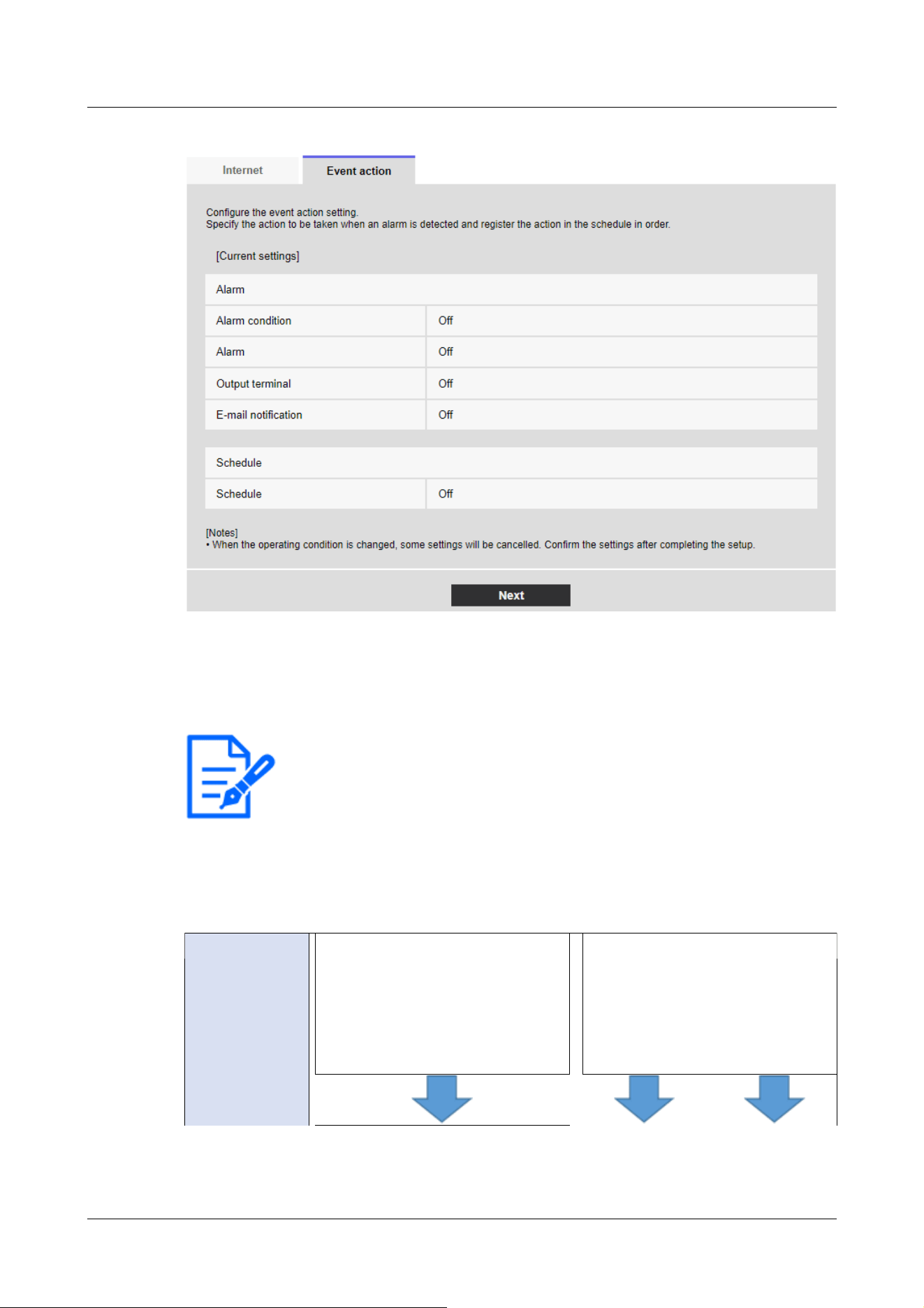
[Note:]
・[FTP/SFTP periodic image transmission] can be selected only for models with
FTP/SFTP features.
・Refer to the catalog specifications for the functions installed in each model.
・Clicking [Next] saves the settings in the window.
Event type
setting
Select the
desired operating
conditions.
Alarm
→7.3.2 Alarm: Sets terminal and
operation detection (alarm setting
screen)
Schedule
→7.3.9 Schedule: Setting
FTP/SFTP Periodic Transmission
(FTP/SFTP Periodic Transmission
Setting Screen)
In event operation, the event operation can be set for SD schedule recording, regular transmission
of FTP/SFTP, and alarm detection. When the settings are complete, press [Next] to proceed.
The configuration flow is as follows.
Event operation flow
7 [Easy Setup] to use easy setting
7.3 [Event action] for setting events
215
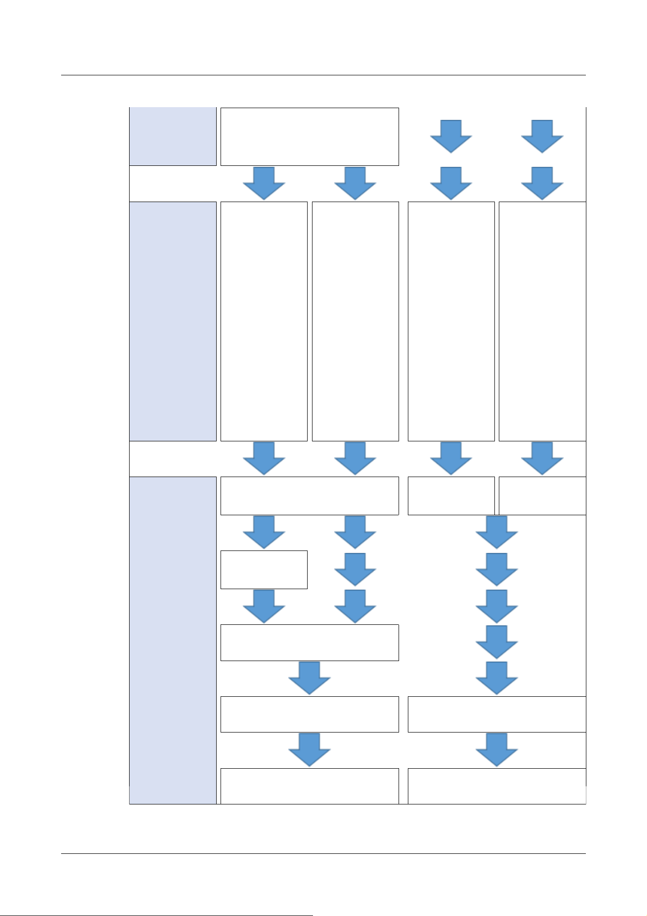
Terminal/VMD/SCD/Audio
detection/Impact detection/Casing
open detection
Event operation
setting
Set the operating
conditions
selected in the
event type
setting.
FTP/SFTP
transfer
→7.3.4 Alarm:
Setting details of
image transfer or
recording
conditions
SD recording
→7.3.4 Alarm:
Setting details of
image transfer or
recording
conditions
SD recording
H.265/H.264
→7.3.8 Schedule:
Set SD recording
(Movie recording
setting screen)
Regular
transmission of
FTP/SFTP
→7.3.9 Schedule:
Setting
FTP/SFTP
Periodic
Transmission
(FTP/SFTP
Periodic
Transmission
Setting Screen)
Event operation
setting
Set the operating
conditions
selected in the
event type
setting.
Recording condition setting
Recording
condition setting
Image transfer
method setting
FTP/SFTP
settings
Alarm output (terminal)
Mail setting Schedule setting
Completion Completion
7 [Easy Setup] to use easy setting
7.3 [Event action] for setting events
216
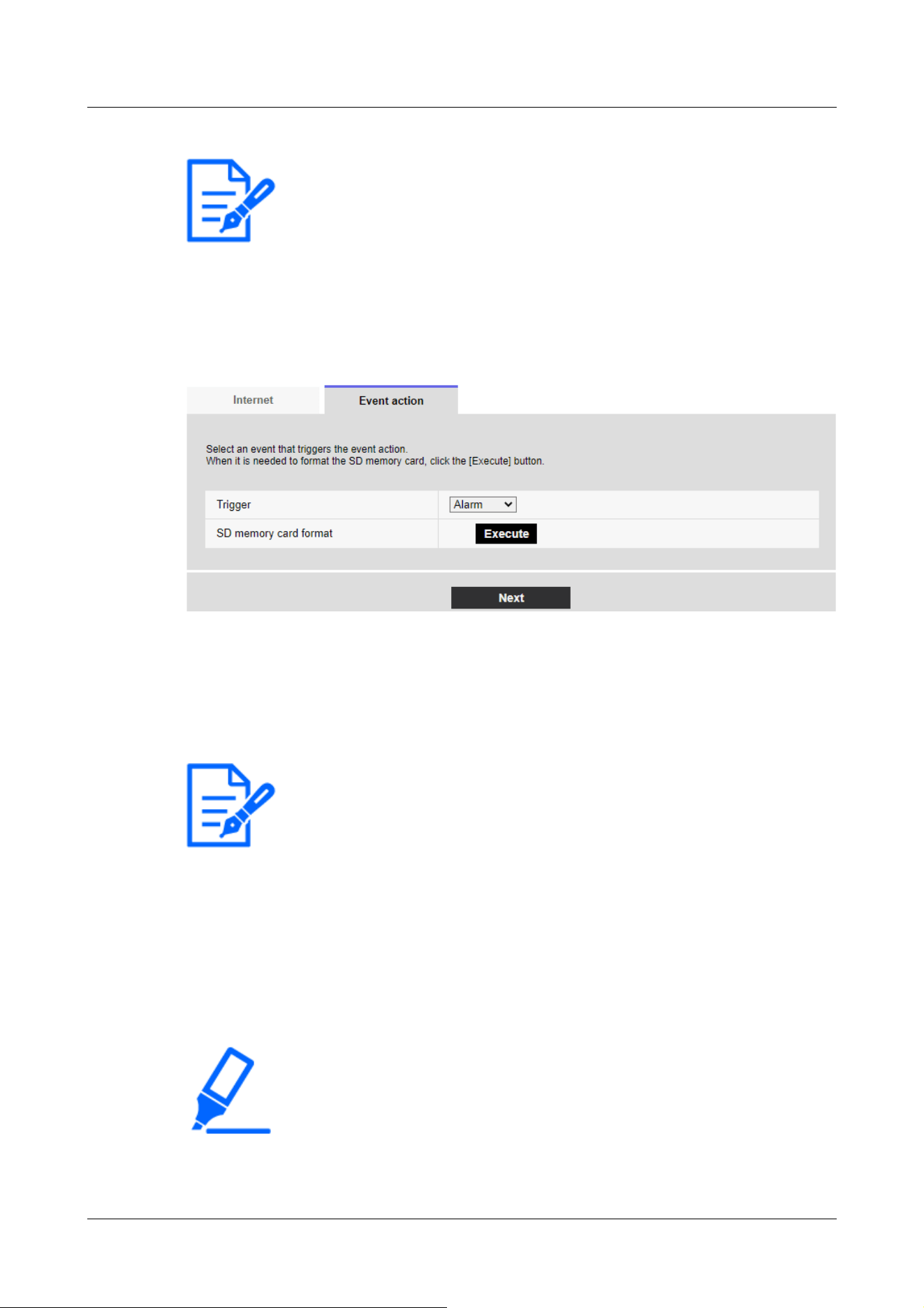
[Note:]
・[MULTI] There is no FTP/SFTP function.
[Note:]
・[FTP/SFTP periodic image transmission] can be selected only for models with
FTP/SFTP features.
・Refer to the catalog specifications for the functions installed in each model.
[Important]
・When formatting is performed, all data stored on the SD Memory Card are deleted.
・Do not turn off the computer during formatting.
7.3.1 Schedule/alarm setting (event type setting screen)
Here, select the type of event.
[Trigger]
[Alarm]:Select this to set the alarm detection.
[Schedule] :[Select this when you want to [FTP/SFTP periodic image transmission] SD-Record.
[SD memory card format]
To format the SD Memory Card, press [Execute].
Clicking [Execute] displays the [Format] confirmation window.
Press the [OK] button to start formatting.
When the [Format] Completion window is displayed, press x.
7 [Easy Setup] to use easy setting
7.3 [Event action] for setting events
217
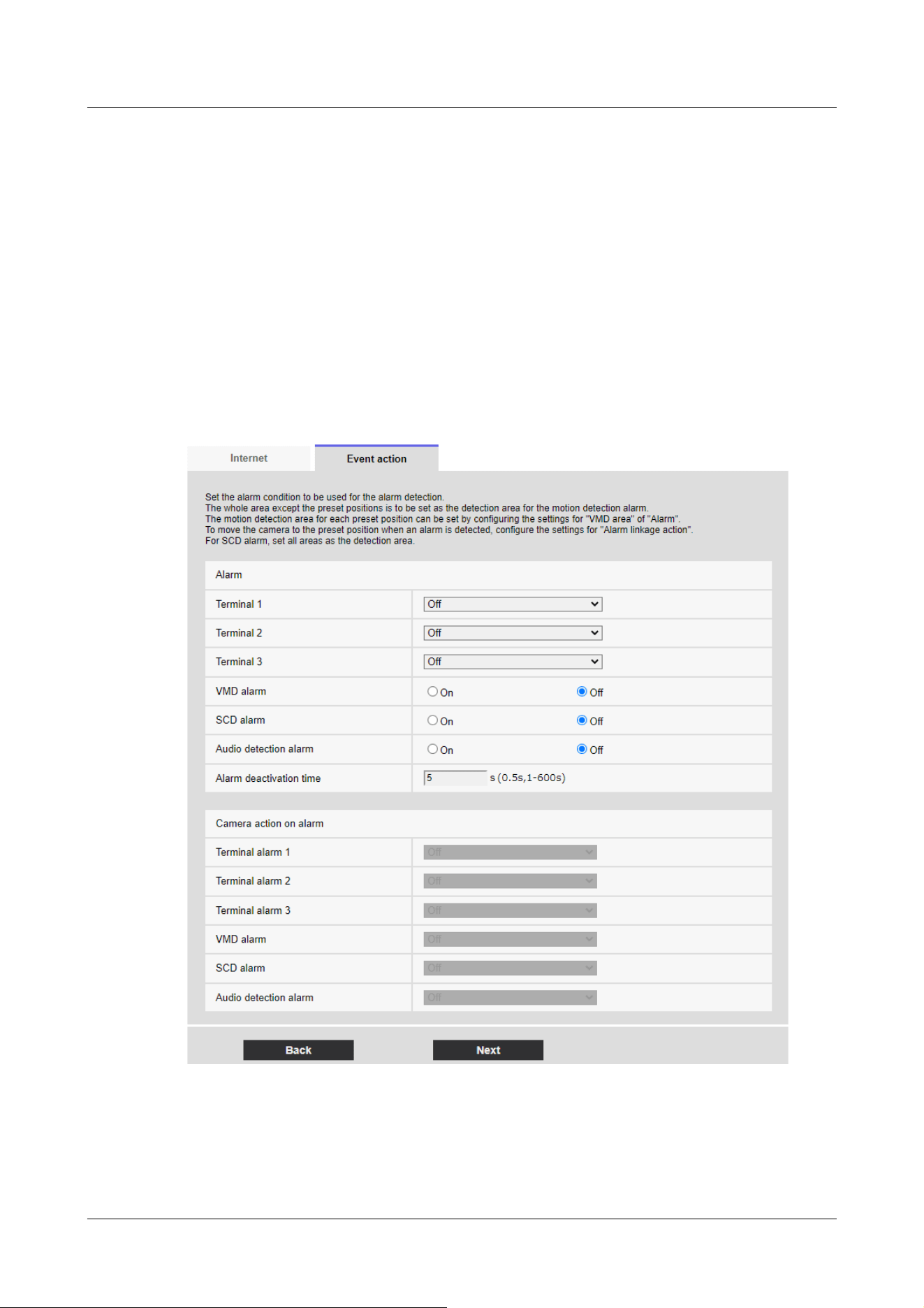
[Next] buttons
Select [Alarm] and press [Next] to open the Alarm Settings window.
→7.3.2 Alarm: Sets terminal and operation detection (alarm setting screen)
Select [Schedule] and press [Next] to open the Schedule Type Settings window.
→7.3.7 Schedule: Set SD recording or FTP/SFTP periodic transmission (Schedule type setting
screen)
7.3.2 Alarm: Sets terminal and operation detection (alarm setting screen)
This section sets the operation when an alarm is detected.
Corner cameras
7 [Easy Setup] to use easy setting
7.3 [Event action] for setting events
218
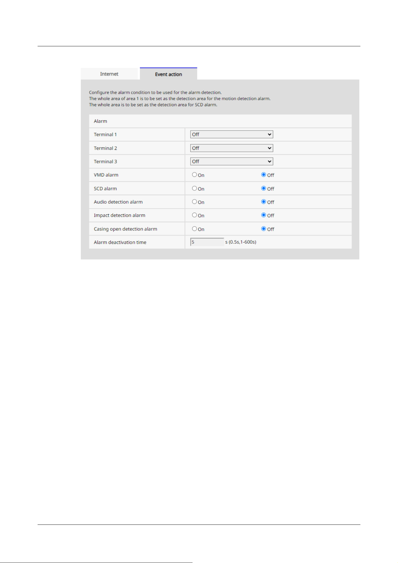
Alarm
[Terminal 1]
Set the operation of terminal 1.
・[Off]:Terminal function is not used.
・[Alarm input(TRM1)]:Terminal alarm input is received.
・[Close]:When the terminal status changes to [On], an alarm is detected.
・[Open]:When the terminal status changes to [Off], an alarm is detected.
・[Close(Continue)]:When the terminal status changes to [On], an alarm is detected. When the
terminal status is [On], the alarm is detected periodically at intervals of no alarm detection
time.
・[Open(Continue)]:When the terminal status changes to [Off], an alarm is detected. When the
terminal status is [Off], the alarm is detected periodically at intervals of no alarm detection
time.
・[Black & white input]:Receives black-and-white selector input. (When the input is [On], the
input is switched to black and white)
・[Auto time adjustment]:Time setting by terminal input is accepted. When the signal is input, set
to 00 minutes 00 seconds if the time difference from the normal time (00 minutes per hour) is 29
minutes or less. In the case of returning the time less than 5 seconds during SD recording, the
time is not changed. Selecting Auto Time Adjustment displays the pull-down menu for short
7 [Easy Setup] to use easy setting
7.3 [Event action] for setting events
219

circuit and release selection.
・[Close]:When the terminal status changes to [Close], the automatic time adjustment is
performed.
・[Open]:When the terminal status changes to [Open], the automatic time adjustment is
performed.
[Terminal 2]
Set the operation of terminal 2.
・[Off]:Terminal function is not used.
・[Alarm input (TRM2)]:The alarm input is received.
・[Short circuit]:When the terminal status changes to [On], an alarm is detected.
・[Open]:When the terminal status changes to [Off], an alarm is detected.
・[Short circuit (Continued)]:When the terminal status changes to [On], an alarm is detected.
When the terminal status is [On], the alarm is detected periodically at intervals of no alarm
detection time.
・[Open (continued)]:When the terminal status changes to [Off], an alarm is detected. When the
terminal status is [Off], the alarm is detected periodically at intervals of no alarm detection time.
・[Alarm Output]:Alarm outputs according to the setting in [Output terminal].
→14.2 [Alarm] for setting the output terminal
[Terminal 3]
Set the operation of terminal 3.
・[Off]:Terminal function is not used.
・[Alarm input (TRM3)]:The alarm input is received.
・[Short circuit]:When the terminal status changes to [On], an alarm is detected.
・[Open]:When the terminal status changes to [Off], an alarm is detected.
・[Short circuit (Continued)]:When the terminal status changes to [On], an alarm is detected.
When the terminal status is [On], the alarm is detected periodically at intervals of no alarm
detection time.
・[Open (continued)]:When the terminal status changes to [Off], an alarm is detected. When the
terminal status is [Off], the alarm is detected periodically at intervals of no alarm detection time.
・[Aux output]:AUX output is performed. The [AUX] buttons appear on the live picture pages.
[VMD alarm]
[On]:If the motion detection area is not set, the entire area is set. To set the VMD area, use the
[VMD area] tab on the alarm page.
→14.6 [VMD area] to set the motion detection area
[Off]:Disables all operation detection status.
7 [Easy Setup] to use easy setting
7.3 [Event action] for setting events
220

[Note:]
・Alarm detection time is managed for each alarm type. For example, the operation
detection alarm is detected even when the alarm of terminal alarm 1 is not
detected.
[Scene change detection (SCD) alarm]
[On]:If the disturbance detection area is not set, the entire area is set. To set up the SCD area,
use the [SCD area] tab on the alarm page.
→14.7 [SCD area] to set up undesired detection
[Off]:Disables all disturbance detection conditions.
[Audio detection alarm]
[On]:Use the sound detection alarm. All AI sounds are recognized.
→14.9 [Audio detection] for setting sound detection
[Off]:Sound detection alarm is not used.
[Impact detection alarm]
[On]:Use the impact detection alarm. Impact detection is recognized.
→14.10 [Impact detection] for setting impact detection
[Off]:Impact detection alarm is not used.
[Casing open detection alarm]
[On]:Use the opening detection alarm. Opening detection is recognized.
→14.11 [Casing open detection] for setting opening detection
[Off]:Opening detection alarm is not used.
[Alarm deactivation time]
Sets the time when the alarm is detected and the detection operation is not executed. For
example, if you set up an e-mail notification to a mobile terminal or a tablet terminal using an
alarm, this setting prevents you from sending too much e-mail.
[0.5s,1-600s]
Alarm linkage operation
[Terminal alarm 1]
Select the action to be interlocked when terminal alarm 1 is detected from the following. This can
be set when [Terminal 1] of the alarm is set to [Alarm input(TRM1)].
7 [Easy Setup] to use easy setting
7.3 [Event action] for setting events
221

[Note:]
・[PTZ] Only PTZ can be selected for [Camera action on alarm].
[Off]:Interlock operation is not performed even if terminal alarm 1 is detected.
1~256:When the preset position registered in advance is selected, the watch moves to the preset
position when terminal alarm 1 is detected.
[Patrol 1]:When terminal alarm 1 is detected, patrol starts.
*When Patrol 1 is not registered, it is not displayed.
[Terminal alarm 2]
Select the action to be interlocked when terminal alarm 2 is detected from the following. This can
be set when [Terminal 2] of the alarm is set to [Alarm input(TRM2)].
[Off]:Interlock operation is not performed even if terminal alarm 2 is detected.
1~256:When the preset position registered in advance is selected, it moves to the position when
terminal alarm 2 is detected.
[Patrol 2]:When terminal alarm 2 is detected, patrol starts.
*When Patrol 2 is not registered, it is not displayed.
[Terminal alarm 3]
Select the action to interlock when terminal alarm 3 is detected from the following. This can be set
when [Terminal 3] of the alarm is set to [Alarm input(TRM3)].
[Off]:Interlock operation is not performed even if terminal alarm 3 is detected.
1~256:Select the preset position registered beforehand to move to the position when terminal
alarm 3 is detected.
[Patrol 3]:When terminal alarm 3 is detected, patrol starts.
*When Patrol 3 is not registered, it is not displayed.
[VMD alarm]
Select the action to be linked to the alarm detected by the motion detector from the following.
[Off]:When an alarm is detected by the motion detector, interlock operation is not performed.
1~256:Selecting the preset position registered beforehand moves the watch to the position when
an alarm is detected by the motion detector.
[Patrol 1]:When an alarm is detected by the motion detector, a patrol is started.
*When Patrol 1 is not registered, it is not displayed.
7 [Easy Setup] to use easy setting
7.3 [Event action] for setting events
222

[Note:]
・Clicking [Next] saves the settings in the window.
[Scene change detection (SCD) alarm]
Select the action to be interlocked when an alarm is detected by the undesired signal detection
from the following.
[Off]:Interlock operation is not performed even if an alarm is detected by undesired signal detection.
1~256:When the preset position registered in advance is selected, the watch moves to the preset
position when an alarm due to disturbance detection is detected.
[Patrol 1]:When an alarm is detected by the disturbance detection, a patrol is started. *When
Patrol 1 is not registered, it is not displayed.
[Audio detection alarm]
Select the action to be linked to the alarm detected by the sound detection from the following.
[Off]:The product does not perform interlocked operation even if an alarm is detected by sound
detection.
1~256:When the preset position registered in advance is selected, the watch moves to the preset
position when an alarm is detected.
[Patrol 1]:When an alarm is detected by sound detection, patrol is started.
*When Patrol 1 is not registered, it is not displayed.
[Next] buttons
Click the [Next] button to open the Alarm type setting window.
→7.3.1 Schedule/alarm setting (event type setting screen)
[Back] button
Returns to the previous screen.
7.3.3 Alarm: Sets operation condition (Alarm type setting screen)
Here, the operation to be performed when the alarm is detected is set.
7 [Easy Setup] to use easy setting
7.3 [Event action] for setting events
223
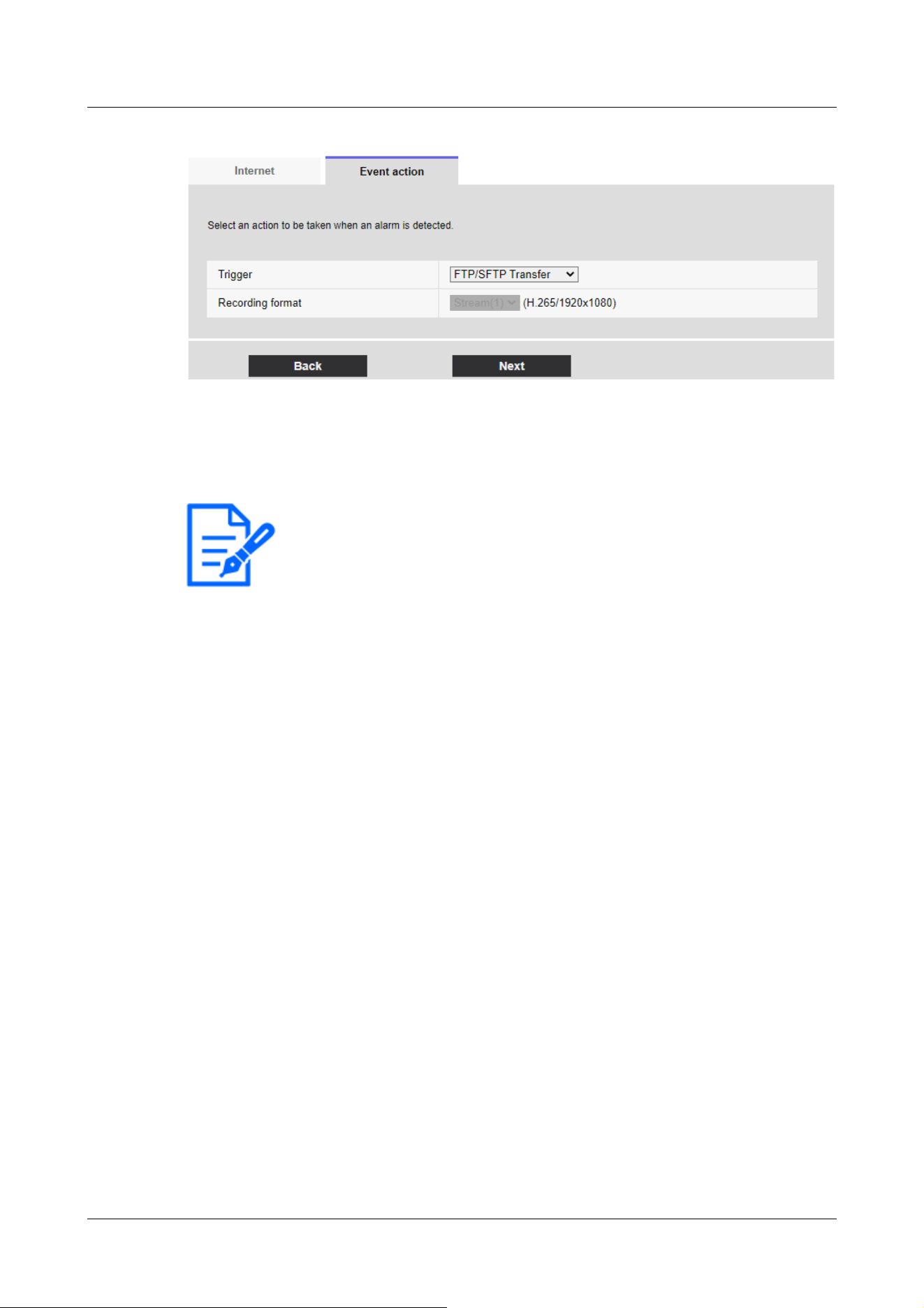
[Note:]
・[FTP/SFTP periodic image transmission] can be selected only for models with
FTP/SFTP features.
・Refer to the catalog specifications for the functions installed in each model.
・[FTP/SFTP] and [[FTP/SFTP periodic image transmission]] can be operated at
the same time when an alarm is generated.
・When [FTP/SFTP Transfer] and [[FTP/SFTP periodic image transmission]] are
set simultaneously when an alarm is generated, [FTP/SFTP Transfer] when an
alarm is generated takes precedence.
[Trigger]
[FTP/SFTP Transfer]:FTP/SFTP transfers JPEG images when an alarm is generated.
[SD memory recording]:Record to SD Memory Card when an alarm is generated.
[Recording format]
When [SD memory recording] is selected in [Trigger], select the compression method for the
images to be recorded from the JPEG/stream.
[Next] buttons
Select [FTP/SFTP Transfer] in [Trigger] and press [Next] to open the FTP/SFTP Transfer
Settings window.
Select [SD memory recording] in [Trigger] and JPEG in [Recording format] and press [Next] to
open the JPEG Record Setting window.
Select "[SD memory recording]" in "[Trigger]" and "[Recording format]" in "Streams" and press
"[Next]" to open the Movie Record Setting window.
→7.3.4 Alarm: Setting details of image transfer or recording conditions
7 [Easy Setup] to use easy setting
7.3 [Event action] for setting events
224

[Note:]
・Clicking [Next] saves the settings in the window.
・The alarm alarm is not recorded on the SD memory card.
[Note:]
・The factors displayed differ depending on the function of the model.
・Refer to the catalog specifications for the functions installed in each model.
[Back] button
Returns to the previous screen.
7.3.4 Alarm: Setting details of image transfer or recording conditions
Setting FTP/SFTP transfer (FTP/SFTP transfer setting screen)
In this case, FTP/SFTP transfer when alarm is detected is set.
7 [Easy Setup] to use easy setting
7.3 [Event action] for setting events
225
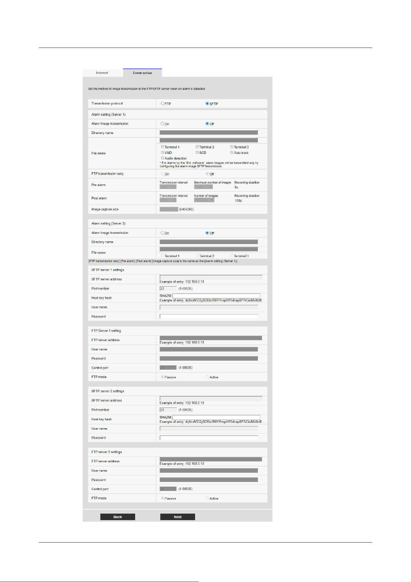
7 [Easy Setup] to use easy setting
7.3 [Event action] for setting events
226
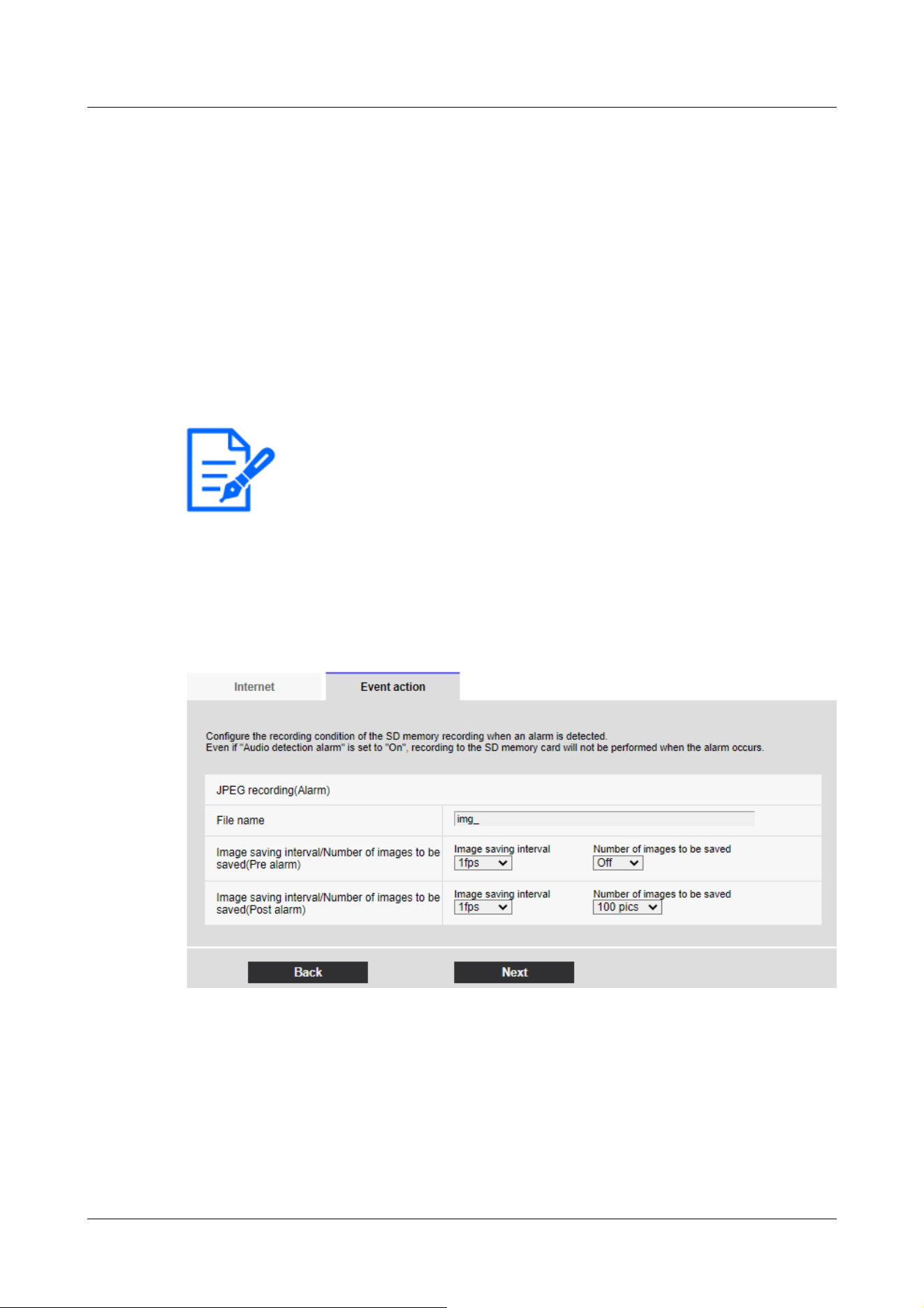
[Note:]
・Clicking [Next] saves the settings in the window.
For details on how to set up the above screen, refer to the following.
→16.2.2 Configuring FTP/SFTP transmission function
[Next] buttons
Select [Alarm output] in the Alarm Settings window and press [Next] to open the Alarm Outputs
dialog box.
→7.3.5 Alarm: Sets output terminal.
If you do not select [Alarm output] on the Alarm Settings screen and [Next] is clicked, the Mail
Settings screen is displayed.
→7.3.6 Alarm: Configuring mail notification and mail server
[Back] button
Returns to the previous screen.
Setting SD recording (JPEG recording setting screen)
The SD recording (JPEG) for alarm detection is set here.
See the [JPEG recording(Alarm)] below for instructions on how to set up the window above.
→9.2 [SD memory card] for setting SD Memory Cards
[Next] buttons
Select [Alarm output] in the Alarm Settings window and press [Next] to open the Alarm Outputs
dialog box.
→7.3.5 Alarm: Sets output terminal.
7 [Easy Setup] to use easy setting
7.3 [Event action] for setting events
227
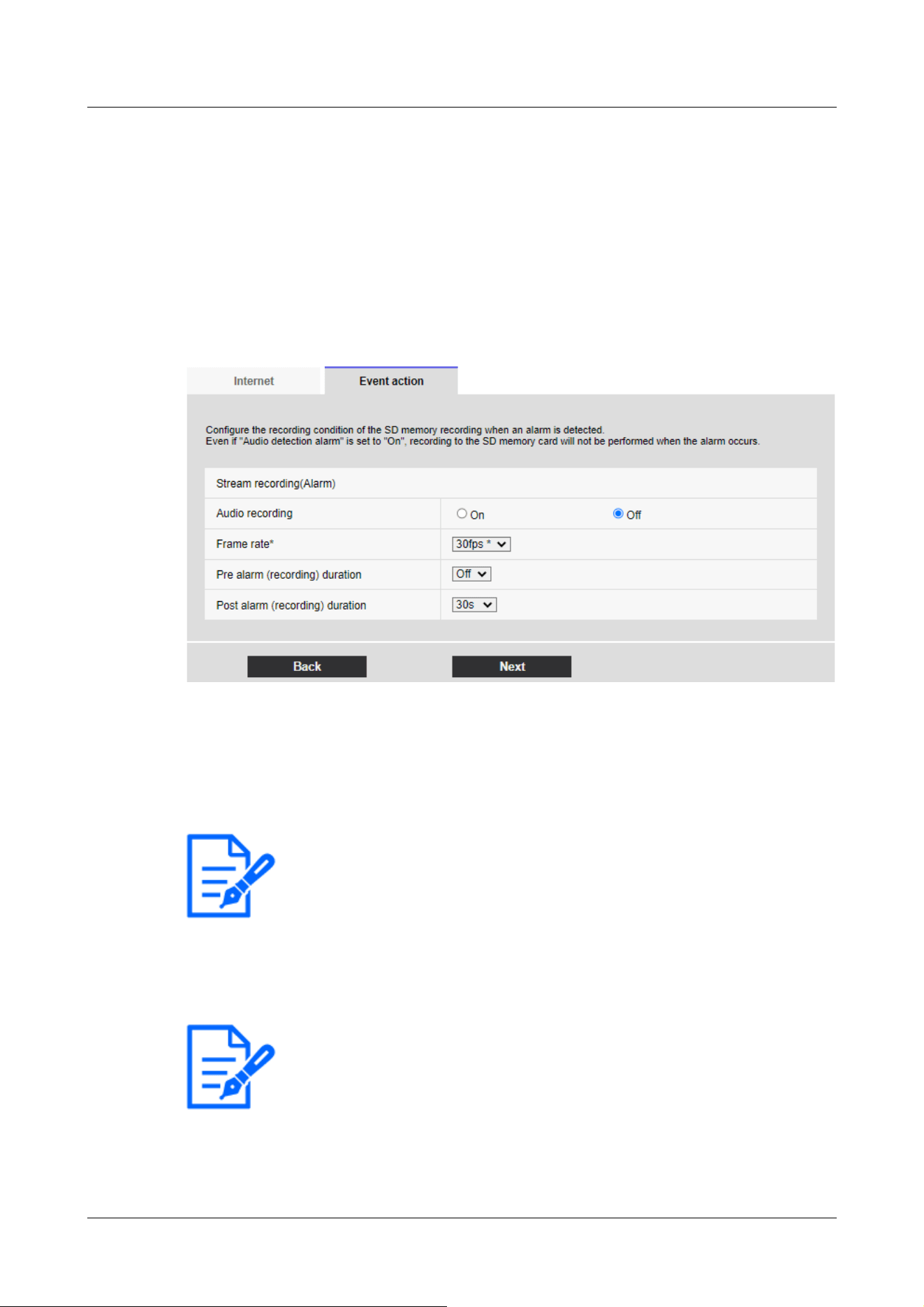
[Note:]
・If the audio distribution mode is set to bi-directional (half duplex), the settings
cannot be made.
[Note:]
・Refer to the [Frame rate*] below for the frame rate you can set and the bit rate
that depends on the frame rate.
→7.3.8 Schedule: Set SD recording (Movie recording setting screen)
If you do not select [Alarm output] on the Alarm Settings screen and [Next] is clicked, the Mail
Settings screen is displayed.
→7.3.6 Alarm: Configuring mail notification and mail server
[Back] button
Returns to the previous screen.
Set SD recording (H.265 or H.264) (Movie recording setting screen)
Here, SD recording (H.265 or H.264) at alarm detection is set.
[Audio recording]
Select whether or not to record audio data with [On] or [Off].
[On]:Audio data is saved in the movie (MP4 format).
[Off]:Audio data is not saved in movies (MP4 format).
Frame Rate
Set the frame rate of H.265 (or H.264) to be recorded.
[Pre alarm (recording) duration]
7 [Easy Setup] to use easy setting
7.3 [Event action] for setting events
228

[Note:]
・The values that can be set depend on the resolution and bit rate of the stream to
be recorded. The higher the bit rate, the smaller the maximum value that can be
set as the pre-alarm time.
[Note:]
・Clicking [Next] saves the settings in the window.
[Note:]
・Refer to the catalog specifications for the functions installed in each model.
Select whether to record before alarm. Sets the time to save to the SD Memory Card.
[Off]/ [1s]/ [2s]/ [3s]/ [4s]/ [5s]/ [8s]/ [10s]/ [15s]/ [20s]/ [25s]/ [30s]/ [40s]/ [50s]/ [60s]/
[90s]/ [120s]
[Post alarm (recording) duration]
Sets the time to save to the SD Memory Card after an alarm is generated.
[10s]/ [20s]/ [30s]/ [40s]/ [50s]/ [60s]/ [120s]/ [180s]/ [240s]/ [300s]
[Next] buttons
Select [Alarm output] in the Alarm Settings window and press [Next] to open the Alarm Outputs
dialog box.
→7.3.5 Alarm: Sets output terminal.
If you do not select [Alarm output] on the Alarm Settings screen and [Next] is clicked, the Mail
Settings screen is displayed.
→7.3.6 Alarm: Configuring mail notification and mail server
[Back] button
Returns to the previous screen.
7.3.5 Alarm: Sets output terminal.
The alarm output is set here. This message is displayed when [Alarm output] is selected in the
alarm setting window.
To set the output terminal:
7 [Easy Setup] to use easy setting
7.3 [Event action] for setting events
229
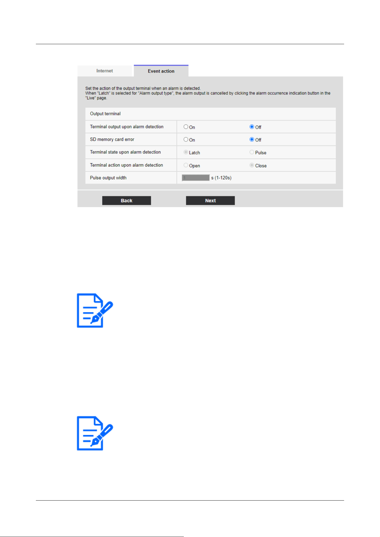
[Note:]
・Clicking [Next] saves the settings in the window.
[Note:]
・The factors displayed differ depending on the function of the model.
・Refer to the catalog specifications for the functions installed in each model.
For details of the settings on the screen above, refer to the following.
→14.2 [Alarm] for setting the output terminal
[Next] buttons
Click the [Next] button to display the mail setting screen.
→7.3.6 Alarm: Configuring mail notification and mail server
[Back] button
Returns to the previous screen.
7.3.6 Alarm: Configuring mail notification and mail server
Here, the settings for mail are made.
7 [Easy Setup] to use easy setting
7.3 [Event action] for setting events
230
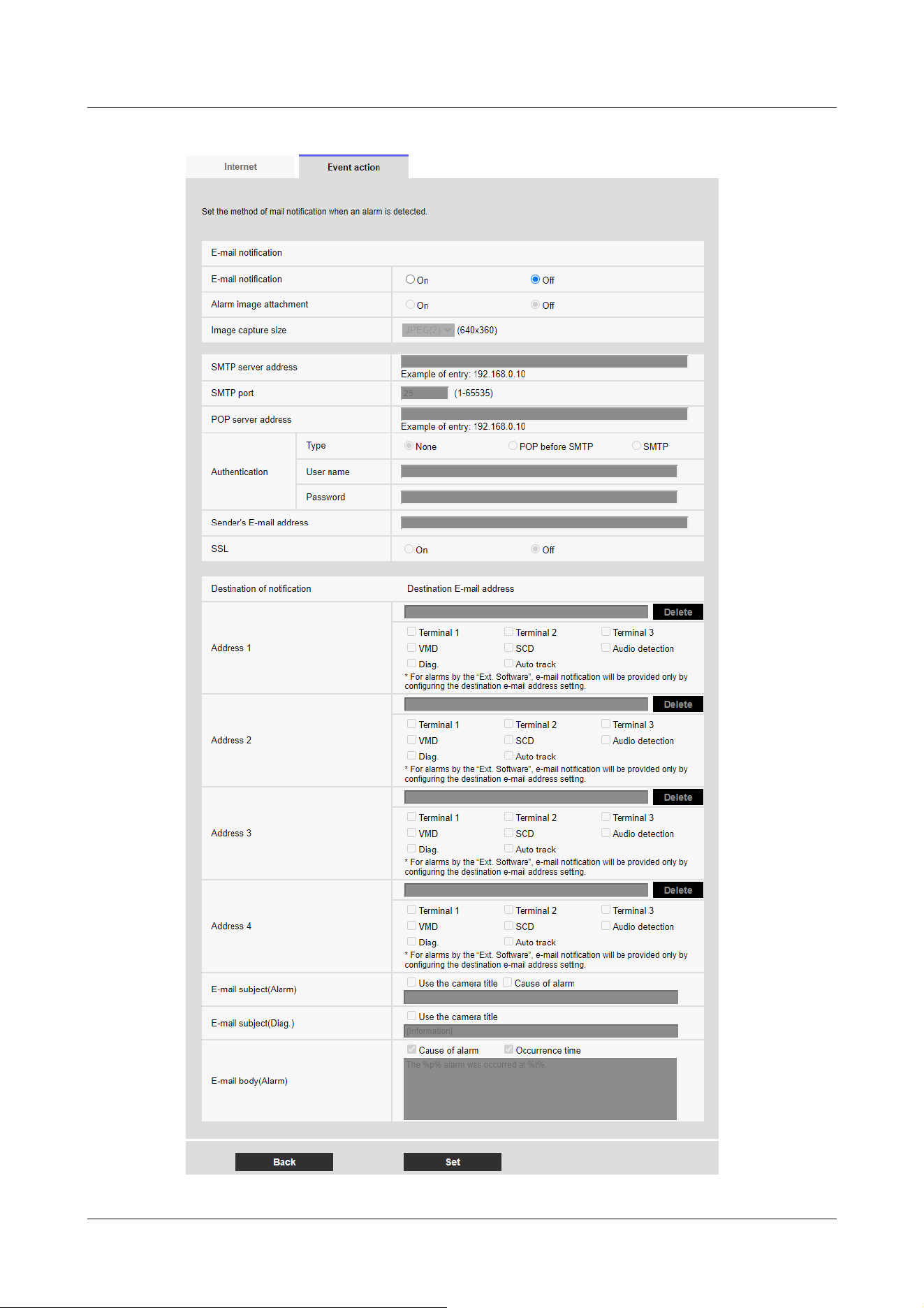
7 [Easy Setup] to use easy setting
7.3 [Event action] for setting events
231
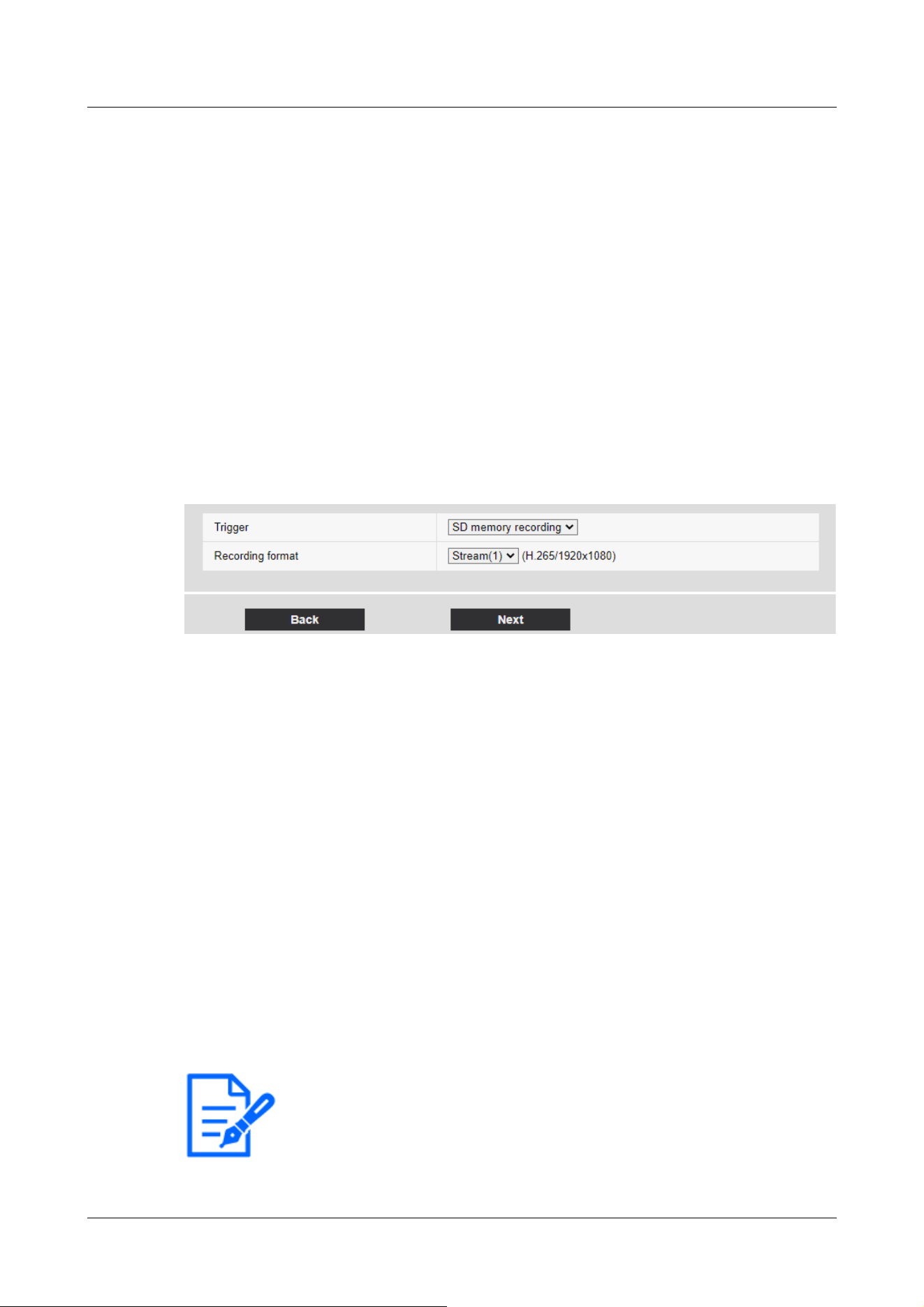
[Note:]
・Clicking [Next] saves the settings in the window.
For details on how to set up the above screen, refer to the following.
→16.2.1 Set mail sending
[Set] buttons
Clicking [Set] completes the setting.
[Back] button
Returns to the previous screen.
7.3.7 Schedule: Set SD recording or FTP/SFTP periodic transmission (Schedule
type setting screen)
Here you set the scheduling type to [SD memory recording] or [FTP/SFTP periodic image
transmission].
[Trigger]
[SD memory recording]:Record H.265 (or H.264) images on the SD Memory Card at the
scheduled time.
[FTP/SFTP periodic image transmission]:The JPEG image is sent to the FTP/SFTP server at the
scheduled time.
[Recording format]
When [SD memory recording] is selected in [Trigger], select the streams to be recorded.
[Next] buttons
Select [SD memory recording] and press [Next] to open the Movie Record Setting window.
→7.3.8 Schedule: Set SD recording (Movie recording setting screen)
Select [FTP/SFTP periodic image transmission] and press [Next] to open the FTP/SFTP Periodic
Transmission Settings window.
→7.3.9 Schedule: Setting FTP/SFTP Periodic Transmission (FTP/SFTP Periodic Transmission
Setting Screen)
7 [Easy Setup] to use easy setting
7.3 [Event action] for setting events
232
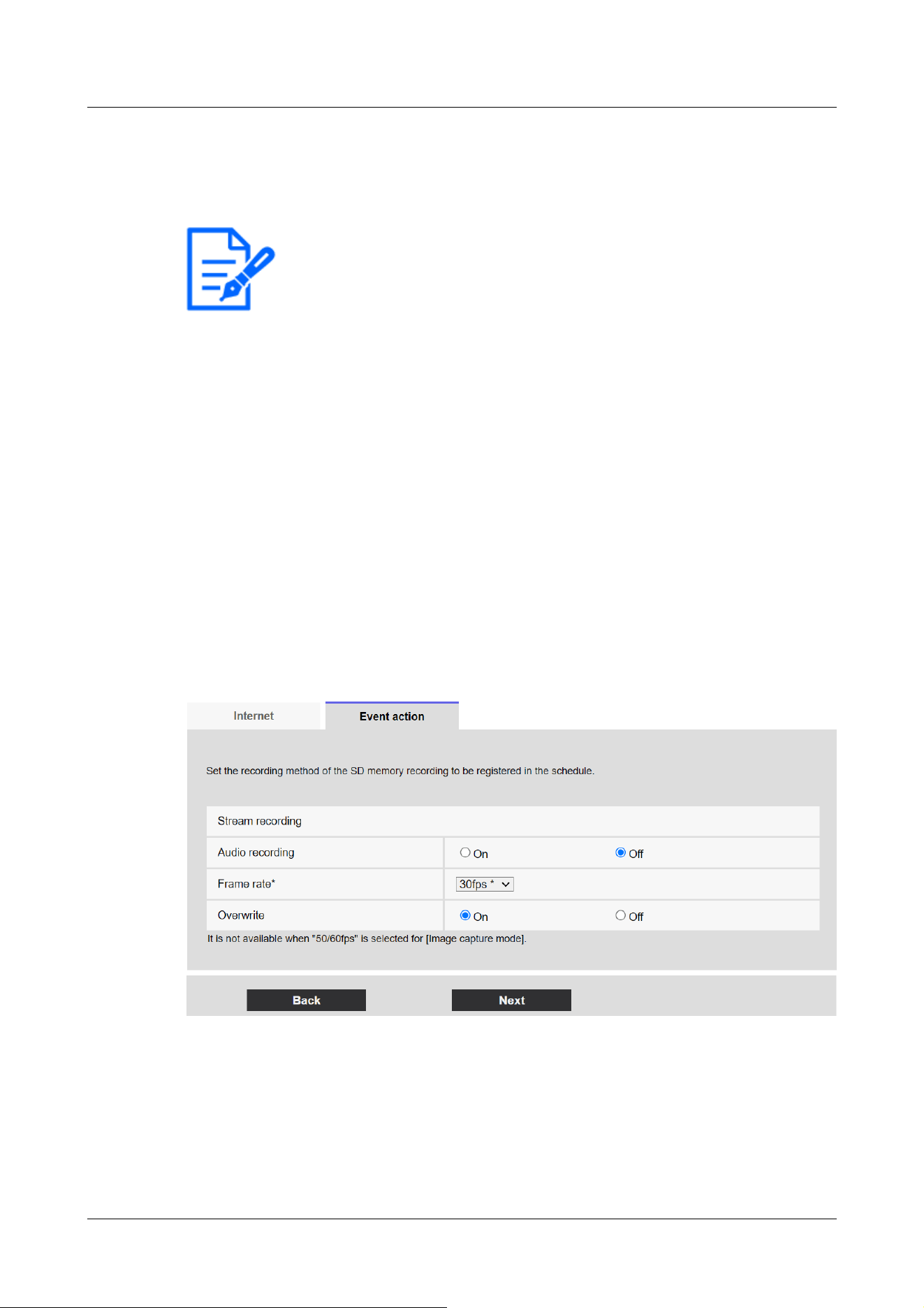
[Note:]
・The [Trigger] [FTP/SFTP periodic image transmission] can be selected only for
models with FTP/SFTP features.
・Refer to the catalog specifications for the functions installed in each model.
・Both [FTP/SFTP periodic image transmission] and [FTP/SFTP] can be operated
simultaneously when an alarm is generated.
・Selecting [SD memory recording] cancels the [FTP/SFTP periodic image
transmission] setting.
[Back] button
Returns to the previous screen.
7.3.8 Schedule: Set SD recording (Movie recording setting screen)
Here, the schedule SD recording (H.265 or H.264) is set.
When the [Next] button is clicked after recording or setting the frame rate on the movie recording
setting screen, the schedule setting screen is displayed and you can set the schedule.
1 The recording, frame rate, and SD Memory Card are overwritten on the movie recording
setting screen.
[Audio recording]
You set whether to record audio data.
[On]:Audio data is saved in the movie (MP4 format).
[Off]:Audio data is not saved in movies (MP4 format).
7 [Easy Setup] to use easy setting
7.3 [Event action] for setting events
233

[Note:]
・If the audio distribution mode is set to bi-directional (half duplex), the settings
cannot be made.
[Important]
・When [Overwrite] is switched from [Off] to [On], the old images may be deleted
to prepare for writing if there is not enough space on the SD Memory Card.
[Note:]
・When [Next] is clicked, [Transmission priority] is set to [Frame rate].
[Important]
・When [Overwrite] is switched from [Off] to [On], the old images may be deleted
to prepare for writing if there is not enough space on the SD Memory Card.
[Frame rate*]
Set the frame rate of H.265 (or H.264) to be recorded from the following.
–If [Image capture mode] is set to 30 fps:
1fps/ 3fps/ 5fps*/ 7.5fps*/ 10fps*/ 12fps*/ 15fps*/ 20fps*/ 30fps*
–If [Image capture mode] is set to 25fps:
1fps/ 3.1fps/ 4.2fps*/ 6.25fps*/ 8.3fps*/ 12.5fps*/ 20fps*/ 25fps*
–If [Image capture mode] is set to 15 fps:
1fps/ 3fps/ 5fps*/ 7.5fps*/ 10fps*/ 12fps*/ 15fps*
–If [Image capture mode] is set to 12.5 fps:
1fps/ 3.1fps/ 4.2fps*/ 6.25fps*/ 8.3fps*/ 12.5fps*
The bit rate is automatically set according to the selected resolution and frame rate. Check the
[Bit Rate* per Client] settings for each stream.
[Overwrite]
You set whether to overwrite and save images when the free space on the SD Memory Card is
running low.
[On]:If the free space on the SD Memory Card decreases, the old image is overwritten and saved
repeatedly.
[Off]:If the SD Memory Card has no free space, the SD Memory Card stops storing data.
7 [Easy Setup] to use easy setting
7.3 [Event action] for setting events
234

[Next] buttons
Clicking [Next] displays the window for setting the recording schedule to the SD Memory Card.
[Back] button
Returns to the previous screen.
2 Set schedule on the Schedule Setting screen.
7 [Easy Setup] to use easy setting
7.3 [Event action] for setting events
235
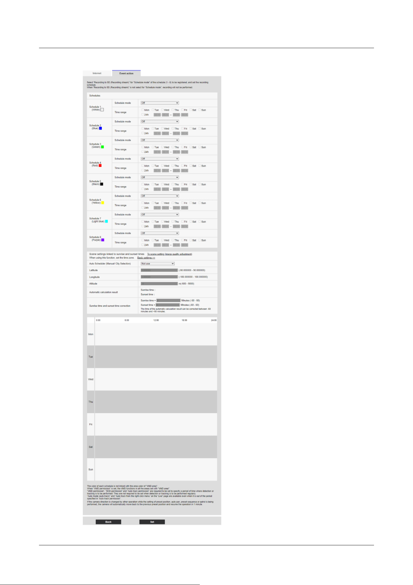
7 [Easy Setup] to use easy setting
7.3 [Event action] for setting events
236

[Note:]
・If [SD memory recording] is not selected in [Operation mode], no recording is
performed.
[Note:]
・Only models with FTP/SFTP functions can be set.
・Refer to the catalog specifications for the functions installed in each model.
For details on how to set up the above screen, refer to the following.
→17 [Schedule] for scheduling
[Set] buttons
Clicking [Set] completes the setting.
[Back] button
Returns to the previous screen.
7.3.9 Schedule: Setting FTP/SFTP Periodic Transmission (FTP/SFTP Periodic
Transmission Setting Screen)
Here, the FTP/SFTP periodic transmission is set.
When [Next] is clicked after periodic transmission and setting of servers on the periodic
transmission setting screen, the periodic transmission schedule setting screen is displayed and the
schedule for periodic transmission can be set.
1 Settings for periodic transmission are made on the Periodic Transmission Setting screen.
7 [Easy Setup] to use easy setting
7.3 [Event action] for setting events
237
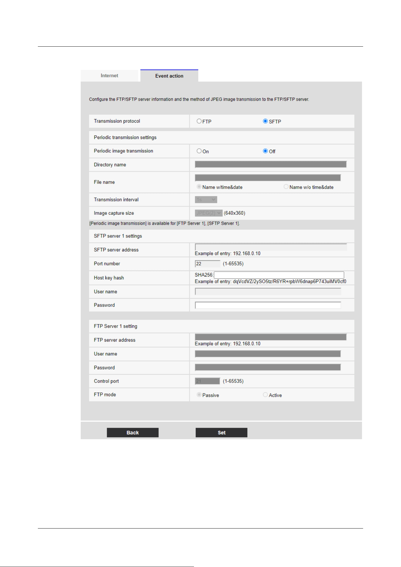
For details of the settings on the screen above, refer to the following.
→16.2.2 Configuring FTP/SFTP transmission function
[Set] buttons
Displayed when [FTP periodic image transmission] is [Off]. Clicking [Set] saves the settings.
[Next] buttons
7 [Easy Setup] to use easy setting
7.3 [Event action] for setting events
238

[Note:]
・Clicking [Next] saves the settings in the window.
Displayed when [FTP periodic image transmission] is [On]. Clicking [Next] displays the window for
setting FTP/SFTP scheduled periodic transmissions.
[Back] button
Returns to the previous screen.
2 Set the schedule for periodic transmission on the Schedule Setting screen.
7 [Easy Setup] to use easy setting
7.3 [Event action] for setting events
239

7 [Easy Setup] to use easy setting
7.3 [Event action] for setting events
240

[Note:]
・If [FTP/SFTP periodic image transmission] is not selected in [Operation mode],
no FTP/SFTP periodic transmission is performed.
For details on how to set up the above screen, refer to the following.
→17 [Schedule] for scheduling
[Set] buttons
Clicking [Set] completes the setting.
[Back] button
Returns to the previous screen.
7 [Easy Setup] to use easy setting
7.3 [Event action] for setting events
241
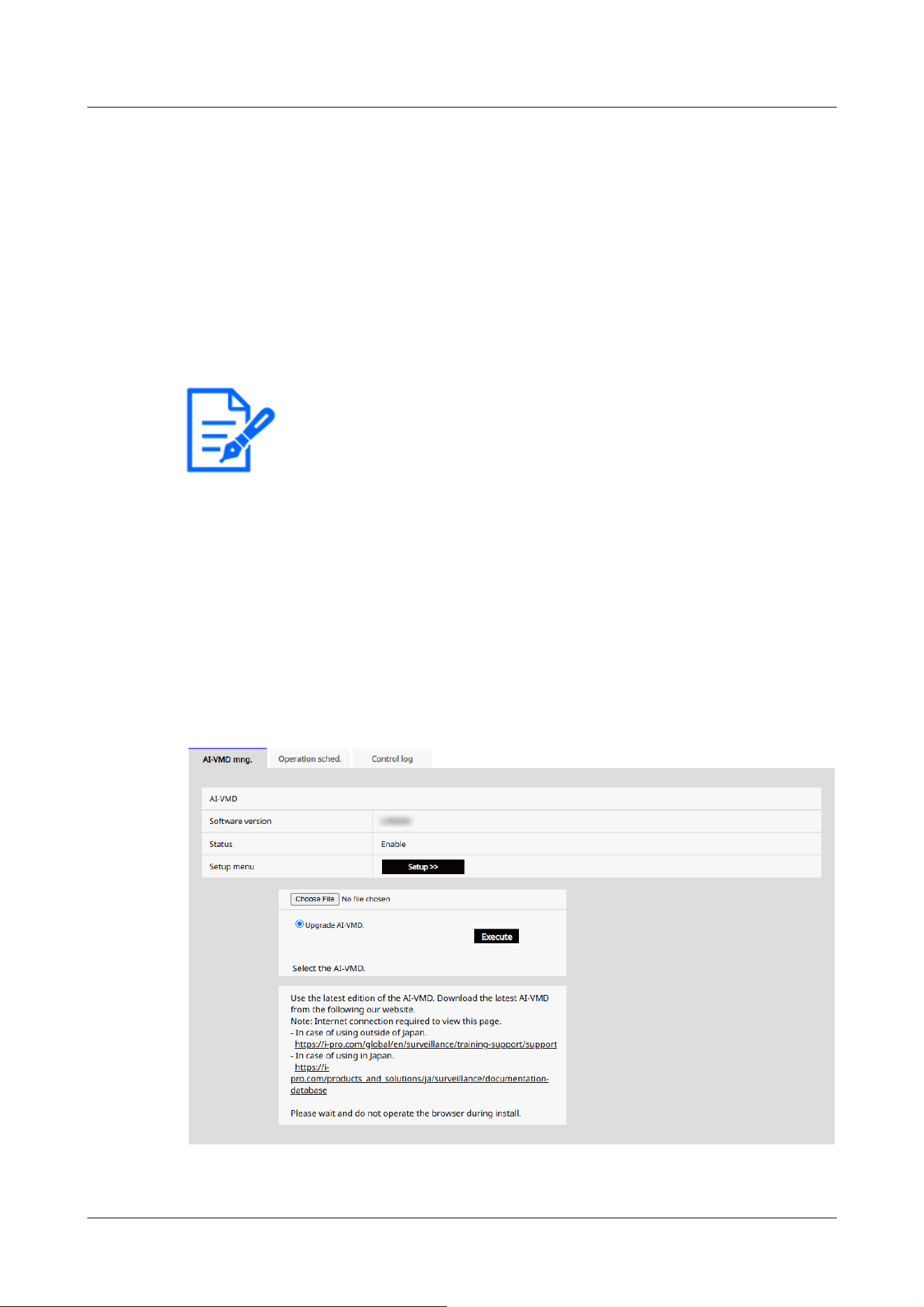
[Note:]
・The items that can be set vary depending on the function installed in the model.
・For the functions of each model, refer to the catalog specifications.
8 Managing Advanced AI-VMD and Scheduling
[AI-VMD]
AI-VMD page allows you to manage AI-VMD and schedule their operation. On AI-VMD page,
this tab consists of the [AI-VMD mng.] tab, [Operation sched.] tab, and [Control log] tab.
8.1 Installing and upgrading AI-VMD [AI-VMD mng.]
On AI-VMD, select the [AI-VMD mng.] tab.For details on how to display and operate the
advanced settings menu, refer to the following.
→5.1 How to display
→5.2 How to operate
8 Managing Advanced AI-VMD and Scheduling [AI-VMD]
8.1 Installing and upgrading AI-VMD [AI-VMD mng.]
242

[Important]
・When using AI-VMD, free RAM space must be at least 50MB.
・If there is not enough RAM space available, AI-VMD cannot be used.If you want
to use AI-VMD, uninstall Extension software installed on [Software mng.] tab.
Alternatively, set [RAM capacity expansion mode] to [On].
→6.1 [Software mng.] for installing, uninstalling, and upgrading function
extension software
AI-VMD
AI-VMD can determine whether the detected moving object is a car (four-wheeled vehicle), a
motorcycle, a bike (two-wheeled vehicle), or a person using AI techniques.
[Software version]
Displays the version-information of AI-VMD.
[Status]
Displays the operating status of AI-VMD.
[Enable]: Appears when AI-VMD is running.
[Disable]: Displayed when AI-VMD is stopped.
[AI-VMD has been uninstalled. Please install the newest AI-VMD]: This message appears when
no AI-VMD is installed on the camera.
[Setup menu]
[AI-VMD setup menu] can be displayed by clicking [Setup >>].
For more information about [AI-VMD setup menu], see "3.2 Choosing Behavior" and later in the
following section:
→https://i-pro.com/products_and_solutions/ja/surveillance/media/documentation_file/doc/
support_and_documentation/xae200w-webguide-ja-pdf
Upgrading AI-VMD
You can upgrade AI-VMD by clicking [Execute].
8.2 [Operation schedule] for Scheduling AI-VMD
On AI-VMD, select [Operation schedule] tab.For details on how to display and operate the
Setting menu, refer to the following.
→5.1 How to display
→5.2 How to operate
8 Managing Advanced AI-VMD and Scheduling [AI-VMD]
8.2 [Operation schedule] for Scheduling AI-VMD
243
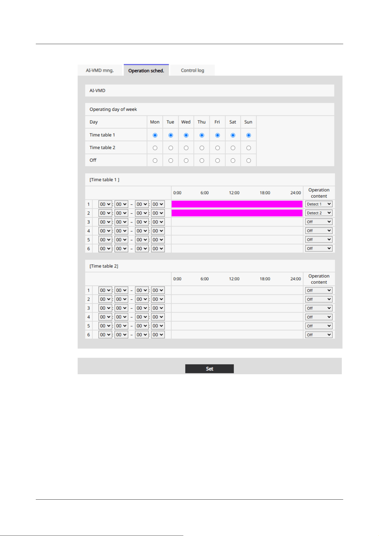
[Time table] [Operation content]
When specifying the time, set the time by clicking [▼].[00:00] When set to [00:00], it is set to 24
hours.Use [Operation content] to set [Detection program 1]/[Detection program 2]/[Off].
How to set the schedule
1 In [Operating day of week], select the day of the week and the timetable for which you want
to schedule.
2 In [Time table] [Operation content], specify the timezone to operate.Specify [00:00] to
[00:00] for 24-hour operation.
8 Managing Advanced AI-VMD and Scheduling [AI-VMD]
8.2 [Operation schedule] for Scheduling AI-VMD
244
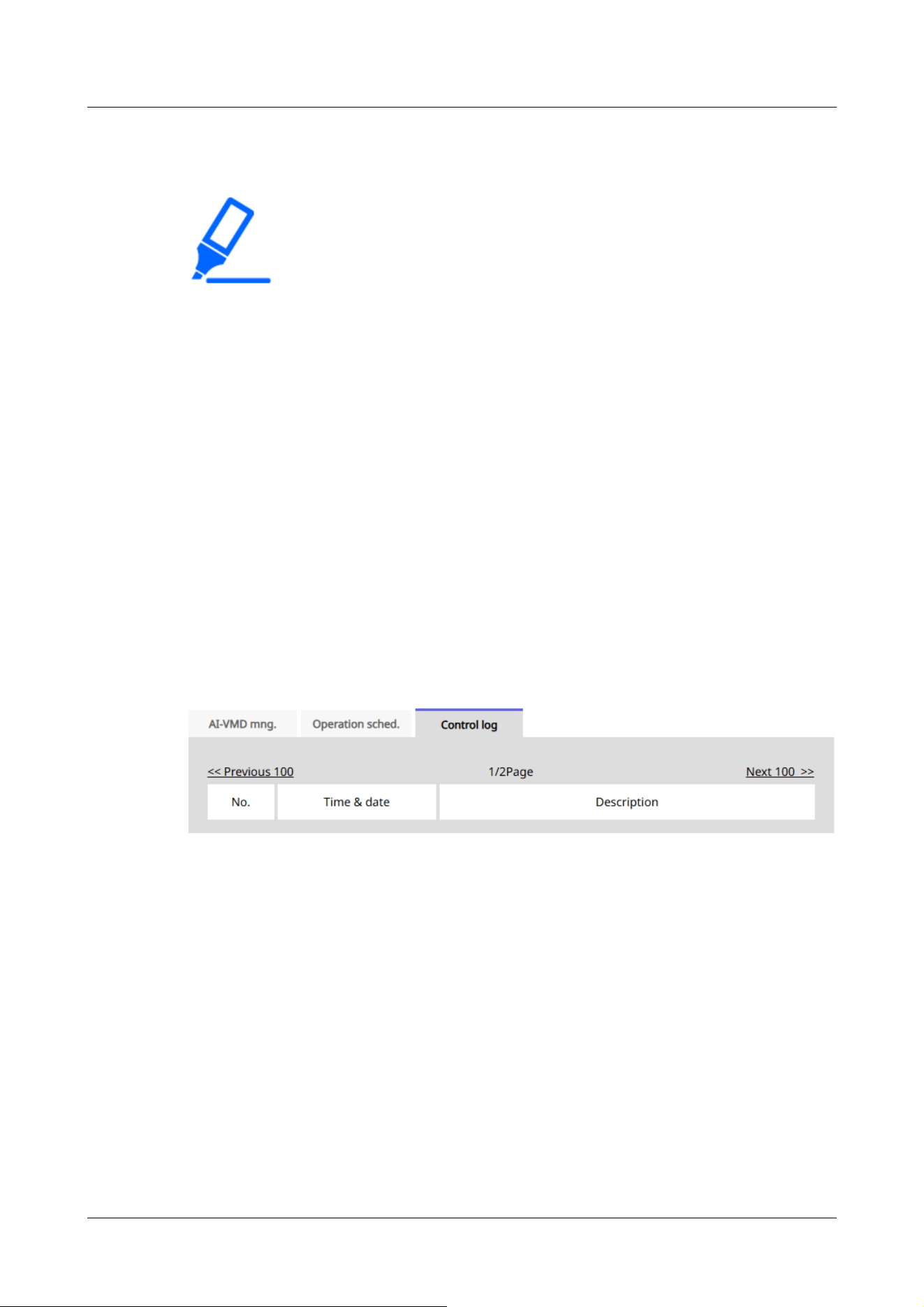
[Note:]
・The operation schedule of AI-VMD is included in the setting data that can be
acquired when [Setting Data (Camera)] is executed in [Data] tab. on the
Maintenance page.
→18.5 [Data] to back up/restore configuration logs
3 When you have finished configuring the settings, press [Set].
8.3 [Control log] for Checking AI-VMD's [Control log]
Displays the administration log for AI-VMD.For details on how to display and operate the Setting
menu, refer to the following.
→5.1 How to display
→5.2 How to operate
Up to 200 management logs can be saved in the internal memory of the computer.
If the maximum number of management logs that can be saved is exceeded, the log is overwritten
from the old log.
100 management logs are displayed and saved even if the camera is turned off.
[Next 100 >>]
Click to display the following 100 entries in the management log list that you are viewing.
[Page number display]
The currently open page is displayed in the form [Page/Total Page].
[<<Previous 100 ]
Click to display 100 items in front of the displayed management log list.
[No.]
The serial number in the control log is displayed.
8 Managing Advanced AI-VMD and Scheduling [AI-VMD]
8.3 [Control log] for Checking AI-VMD's [Control log]
245

[Time & date]
The date and time when the log occurred is displayed.
[Description]
The contents of the management log are displayed.
For the contents of each control log, please refer to our technical information website.<Control
number: C0317>
8 Managing Advanced AI-VMD and Scheduling [AI-VMD]
8.3 [Control log] for Checking AI-VMD's [Control log]
246

[Note:]
・The layout of each setting item varies depending on the model.
・Refer to the catalog specifications for the functions installed in each model.
[Note:]
・The layout of each setting item varies depending on the model.
・Refer to the catalog specifications for the functions installed in each model.
9 [Basic] for basic setup of the machine
Basic pages set the camera title, date and time, SD Memory Card, and overlay. The basic pages
consist of the [Basic], [SD memory card], and [Overlay image] tabs.
9.1 [Basic] to perform basic settings
On the Basic Page, press the [Basic] tab. Refer to the following how to display and operate the
Advanced menu.
→5.1 How to display
→5.2 How to operate
The camera title, date, and time are set here.
[Menu language]
Select the first language that appears when you access the camera from the list below.
[Auto]/[English]/[Japanese]/[Italian]/[French]/[German]/[Spanish]/[Chinese]/[Russian]/
[Portuguese]
[Auto]:The language used by the browser is automatically selected. If the machine does not
support the language, the English language is selected.
[Camera title]
Enter the name of the computer. After input, press [Set] to display the entered name in the
camera title.
Number of characters that can be entered:0 to 20 characters
Characters that cannot be entered:Half-pitch symbol " &
9 [Basic] for basic setup of the machine
9.1 [Basic] to perform basic settings
247

[Important]
・If you need to set the time more accurately in system operation, use the NTP
server.
→16.2.3 Set up an NTP server
[Note:]
・[MULTI] [Date/time display] can be set individually by the cameras.
[Date/time]
Enter the current date and time. If you selected [12h] in [Time display format], select [AM] or
[PM].
When [Set PC time to the camera] is checked and [Set] is clicked, the date and time of the
computer are obtained and set to the computer.
Settable range:Jan/01/2013 00:00:00~Dec/31/2035 23:59:59
[Date/time display]
Use [On] or [Off] to set whether the date and time are displayed on the images. When the date
and time are not displayed, set it to [Off].
[Time display format]
Select the time display method from 24h/12h. Enter the [Date/time] according to this setting.
[Date/time display format]
Select the date display format. If [Date/time] is set to [13:10:00 on April 1, 2022], the display
formats are as follows.
DD/MM/YYYY: 01/04/2022 13:10:00
MM/DD/YYYY: 04/01/2022 13:10:00
DD/Mmm/YYYY: 01/Apr/2022 13:10:00
YYYY/MM/DD: 2022/04/01 13:10:00
Mmm/DD/YYYY: Apr/01/2022 13:10:00
[Date/time position]
Select the position where the date and time are displayed on the image.
[Upper left]: Displayed in the upper left corner of the window.
[Lower left]: Displayed in the lower left corner of the window.
[Upper center]: Displayed in the center of the window.
[Lower center]: Displayed at the bottom center of the window.
[Upper right] is displayed in the upper right corner of the window.
9 [Basic] for basic setup of the machine
9.1 [Basic] to perform basic settings
248

[Note:]
・[MULTI] [Date/time position] can be set individually by the cameras.
[Note:]
・[MULTI] When Image capture mode is in Quad/Dual mode, Camera 1 is
automatically selected and other cameras cannot be selected.
・[MULTI] Select Camera 1 in [Display on screen] and select [Reflect all settings
for Camera 1] to set the settings you changed for Camera 1 to all other cameras.
[Lower right]: Displayed in the lower right corner of the window.
[NTP]
Clicking [NTP >>] displays the [Advanced] tabs for the network pages.
→16.2.3 Set up an NTP server
[Time zone]
Select the time zone for the camera area.
[Summer time(daylight saving)]
Use [In], [Out] and [Auto] to specify whether to use Daylight Saving Time. Set in the region where
Daylight Saving Time is used.
[In]:Set the time to Daylight Saving Time. [*] is displayed in the time display.
[Out]:Reset Daylight Saving Time.
[Auto]:Switches to Daylight Saving Time according to the start date and time and end date
settings (month, week, day of week, time).
[Start time & date] [End time & date]
When [Auto] is selected in [Summer time(daylight saving)] Setting, the start date and time of
Daylight Saving Time and the end date and time of Daylight Saving Time are set in Month, Week,
Day of Week, and Time.
[Display on screen]
To make individual settings, select the camera and set the settings.
Select the camera to set the following items individually for each camera.
[Date/time display]
[Date/time position]
[Camera title on screen display]
[Camera title position]
[Camera title on screen display]
9 [Basic] for basic setup of the machine
9.1 [Basic] to perform basic settings
249

[Note:]
・[MULTI] [Camera title on screen display] can be set individually by the cameras.
[Note:]
・Up to two lines of [Camera title on screen] can be set.
・[MULTI] [Camera title on screen] can be set individually by the cameras.
[Note:]
・[MULTI] [Camera title position] can be set by cameras.
Use [On]/[Off] to set whether the strings are displayed on the images.
When set to [On], the character strings entered in [Camera title on screen] are displayed at the
position selected in [Position].
[Camera title on screen]
Enter a character string to be displayed in the image.
Number of characters that can be entered:0 to 40 characters
Input Characters:One-byte (0-9, A-Z, a-z), two-byte (kanji, hiragana, katakana, alphanumeric),
one-byte and two-byte symbols ! " # $ % & ' ( ) * + , ‑ . / : ; = ?
[Camera title position]
Select the position where the character string is displayed in the image.
[Upper left]:Displays in the upper left corner of the screen.
[Lower left]:Displays in the lower left corner of the screen.
[Upper center]:Displayed in the center of the screen.
[Lower center]:Displays at the bottom center of the screen.
[Upper right]:Displayed in the upper right corner of the screen.
[Lower right]:Displays in the lower right corner of the screen.
Date and time&In-Screen Characters > [Display type]
Sets the display format to either [Permeation] or [Opaque].
[Permeation]:Displays the date and time and characters on the screen in transparent characters.
[Opaque]:Displays date and time and on-screen characters in opaque (black-coated) characters.
Date and time&In-Screen Characters > [Character size]
Select the date and time displayed in the image and the character size of the character string.
9 [Basic] for basic setup of the machine
9.1 [Basic] to perform basic settings
250

[Important]
・If the [Date/time position] and [Camera title position] settings are different, the
frame rate may be lower than the set value.
・If the [Date/time position] and [Camera title position] settings are different, the
characters may run out or overlap depending on the [Character size] setting and
the number of characters. Confirm the display results before use.
・If [Character size] is set to [150%] or [200%], the frame rate may be lower than
the set value.
・Depending on the [Character size] setting and the number of characters or the
resolution of the images, it may be displayed only halfway or difficult to read.
Confirm the display results before use.
・[PTZ][AI Outdoor IR Bullet] If [Character size] is set to [150%] or [200%],
[Camera title on screen]'s [Line 2] will no longer be displayed.
[Note:]
・Even if 50% and 75% are set, the images of 640 x 360, VGA, 320 x 180, and
QVGA show 100% [Camera title on screen].
・If [Detailed setting] [Overlay] is set to [On], the date and time&Characters on
the Screen: You cannot set [150%] or [200%] in [Character size].
[Note:]
・The brightness display in the image is displayed when the brightness is adjusted
on the system device.
50%:The standard 50% size is displayed.
75%:Displays the standard 75% size.
100%:Displays the standard size.
150%:This is displayed as 150% of the standard size.
200%:Displayed as 200% of standard size.
[Brightness status display]
ON/OFF is used to set whether the brightness status is displayed when adjusting the brightness.
[Stabilizer]
ON/OFF is used to specify whether or not the camera's shaking correction function is enabled.
The gyroscope sensor can be used to compensate for low-frequency vibrations such as pole
vibrations caused by wind and fine vibrations at high magnification, thereby shooting images with
9 [Basic] for basic setup of the machine
9.1 [Basic] to perform basic settings
251

[Important]
・When set to [On], the field angle is narrowed. When set to [On], check the field
angle when mounting the camera.
・Picture correction does not work in the following cases.
Pan and tilt zoom are executing.
During position refresh
・In the following cases, it may not be possible to obtain sufficient shaking
compensation depending on the shooting conditions.
When the subject is dark
-Rapid oscillation, such as mechanical vibration
Large-amplitude shaking
-Image quality/position setting in progress
・If the [Stabilizer] setting is changed with the following area set, the set area will
be misaligned. Set [Stabilizer] and then set the respective areas.
-Privacy zone
-VMD area
-SCD area
-VIQS area
-Mask area
-overlay image
-Focus frame
・[New X Fixed][AI Outdoor IR BulletX]This function is not available when [Image
capture mode] is set to [60fps Mode] or [50fps Mode].
・[New X Fixed][AI Outdoor IR BulletX]If you change the setting from [On] to
[Off], it restarts automatically.
・[New X Fixed][AI Outdoor IR Bullet]When set to [On], [90°] and [270°] of
[Image rotation] cannot be used.
・[New X Fixed]When set to [On], [Lens distortion compensation] cannot be used.
・[New X Fixed-2M][New X Fixed-5M]When set to [On], the zoom factor is
.
.
less blurring.
Use this function only when the camera is installed in an environment in which the camera
frequently swings. It is effective to reduce the vibration.
Check the operation during installation.
Do not use the shaking correction function when using the product in an environment where there
is no shaking.
9 [Basic] for basic setup of the machine
9.1 [Basic] to perform basic settings
252

limited to up to 3.1 times.
・[New X Fixed-8M][New X Fixed-6M]When set to [On], the zoom factor is
limited to up to 2 times.
・[AI Outdoor IR BulletX]When set to [On], [Digital zoom] cannot be used.
[Note:]
・When shaking occurs in a dark shooting environment, the shaking correction
effect may be improved by setting the maximum exposure time to [1/100s] or
faster shutter setting. Set the maximum exposure time depending on the
installation environment.
・When [Stabilizer] is set to [On], the superdynamic setting is [Off].
・[PTZ][AI Outdoor IR BulletS]When [Stabilizer] is set to [On], the digital zoom
factor is limited to half.
・Refer to the catalog specifications for the functions installed in each model.
[Important]
・If the [Image rotation] setting is changed with the following area set, the set area
will be misaligned. Set [Image rotation] and then set the respective areas.
-Privacy zone
-VMD area
-SCD area
-VIQS area
-Mask area
-overlay image
-Focus frame
・If [Image rotation] is set to [90°] or [270°], the on-screen characters may be
broken depending on the [Character size] setting and the number of characters.
・When [Image rotation] is set to [90°] and [270°], the positions that can be set
to [Date/time position] and [Camera title position] are limited to [Upper left] and
[Lower left].
・[New X Fixed][AI Outdoor IR BulletX]When [Stabilizer] is [On] and [Image
rotation] is set to [90°] or [270°] from an external device, the system
automatically restarts.
・[New X Fixed][AI Outdoor IR Bullet]When [Image rotation] is set to [90°] or
[Image rotation]
Select from [0 °(Off)], [90°] and [180 °(Upside-down)], and [270°].
9 [Basic] for basic setup of the machine
9.1 [Basic] to perform basic settings
253

[270°], [Stabilizer] cannot be used.
・[New X Fixed][AI Outdoor IR BulletX]When [Image rotation] is set to [90°] or
[270°] and 320x180, QVGA images are displayed, characters in the images may
be cut off.
・[AI Outdoor IR BulletS-8M]When [Image rotation] is set to [90°] or [270°],
the frame rate is limited to a maximum of 15fps (maximum 12.5fps in 25fps mode).
[Note:]
・Depending on the [Image capture mode], you may not be able to set the [Image
Rotation] to [90°] or [270°].
・If [Image capture size] is 320 x 180, [Image rotation] cannot be set to 90° or
270°.
・[New X Fixed][AI Outdoor IR BulletX]Even when [Image capture size] is set to
320x180, you can set [Image rotation] to 90° or 270°.
・Refer to the catalog specifications for the functions installed in each model.
[Note:]
・If [Image rotation] is set to [90°] or [270°], the mirror inversion is fixed in
[Off].
[Note:]
・Refer to the catalog specifications for the lamps installed in each model.
・[MULTI_PTZ] [Indicator] can be set from the PTZ-camera.
[Mirror]
Use [On]/[Off] to set whether the images are reversed left or right.
[Indicator]
Select the ON/OFF status of the lamp. To check the operation status with the lamps, select
[On].
[FunctionLED]
Select the operation to be notified by [FunctionLED]. Multiple operations can be selected.
[REC notification]:The [FunctionLED] lights when the camera is recording video distribution or
when the camera video is being distributed.
[Impact detection notification]:The [FunctionLED] indicator flashes when the camera receives an
impact.
9 [Basic] for basic setup of the machine
9.1 [Basic] to perform basic settings
254

[Note:]
・When [Impact detection notification] is selected, [FunctionLED] flashes after the
camera receives an impact. The [FunctionLED] will go out one minute after the
flashing starts.
・When [Casing open detection notification] is selected, [FunctionLED] flashes
while the front cover is open. The [FunctionLED] will go out when the front cover
is closed.
・Even if [Indicator] is set to [Off], [FunctionLED] is not turned off. To turn off the
[FunctionLED], remove all the checks.
[Note:]
・When [Audio out] is set to [Audio], [Monitor out] cannot be selected.
・If you set [Audio transmission mode] to other than [Off] or [Mic input], you
cannot set [Audio out] to [Monitor].
・If you set [Audio out] to [Monitor], you cannot set [Audio transmission mode] to
anything other than [Off] or [Mic input].
[Note:]
・The [Monitor out] setting can be changed when the imaging mode is 30 fps, 60
fps, or 15 fps.
・[PTZ]The output image may be reversed up or down.
・[New X Fixed][AI Outdoor IR BulletX]The output image is rotated according to
the [Image Rotation] setting.
[Casing open detection notification]:When the front cover of the camera is opened,
[FunctionLED] blinks.
[Audio out]
Sets whether to use the audio output terminal as the adjustment monitor output.
Audio/monitor
[Monitor out]
Set the image format to be output from the image output terminal (MONITOR OUT).
NTSC/PAL
[Tilt adjustment lever position]
Set the [Tilt adjustment lever position] set when the camera is installed.
[High]/ [Mid]/ [Low]
9 [Basic] for basic setup of the machine
9.1 [Basic] to perform basic settings
255

[Note:]
・[MULTI_PTZ] The [Tilt adjustment lever position] can only be selected for the
Multi-directional camera settings.
[Note:]
・[New X Fixed][AI Outdoor IR BulletX] When [Image capture mode] is set to
[60fps Mode] or [50fps Mode], [Privacy Zone Format] cannot be set to [Blurring].
[Privacy Zone Format] is set to [Block].
・[New X Fixed] If [Privacy Zone Format] is set to [Blurring], [Lens distortion
compensation] cannot be used.
・[New X Fixed-8M][New X Fixed-5M][AI Outdoor IR BulletX-8M][AI Outdoor IR
BulletX-5M] When [Privacy Zone Format] is set to [Blurring], the frame rate is
limited to the maximum 15fps when the maximum 12.5fps(25fps mode is selected).
・[New X Fixed-2M][New X Fixed-5M] When [Privacy Zone Format] is set to
[Blurring], the zoom ratio is limited to a maximum of 3.1 times.
・[New X Fixed-8M] When [Privacy Zone Format] is set to [Blurring], the zoom
factor is limited to up to 2 times.
・[AI Outdoor IR BulletX] When [Privacy Zone Format] is set to [Blurring],
[Digital zoom] cannot be used.
・[Blurring] in [Privacy Zone Display Format] and [AI Privacy Guard (WV-
XAE201W)] cannot be used at the same time.
[Privacy zone display format]
Selects the display format of Privacy Zone from [Block] and [Blurring].
Click [Privacy Zone Settings] to display the [Privacy Zone Area Settings] screen of the image
quality page.
→10.4.6 Setting the privacy zone (Privacy zone setting screen)
[Relay output]
Sets whether to enable [Wiper] pull-down menu [Washer] for Live image pages. For information
about [Wiper], refer to the following.
→2.3.2.2 Live image pages of the PTZ camera
[On]:Connects the contact points of the "-" and "+" relay pins.
[Off]:Disconnects the contact points of the "-" and "+" relay pins.
[Washer control]:When this option is selected, Gray out of [Washer] pull-down menu of [Wiper]
of Live image pages is deselected and can be selected. At that time, the [Washer control] link is
9 [Basic] for basic setup of the machine
9.1 [Basic] to perform basic settings
256
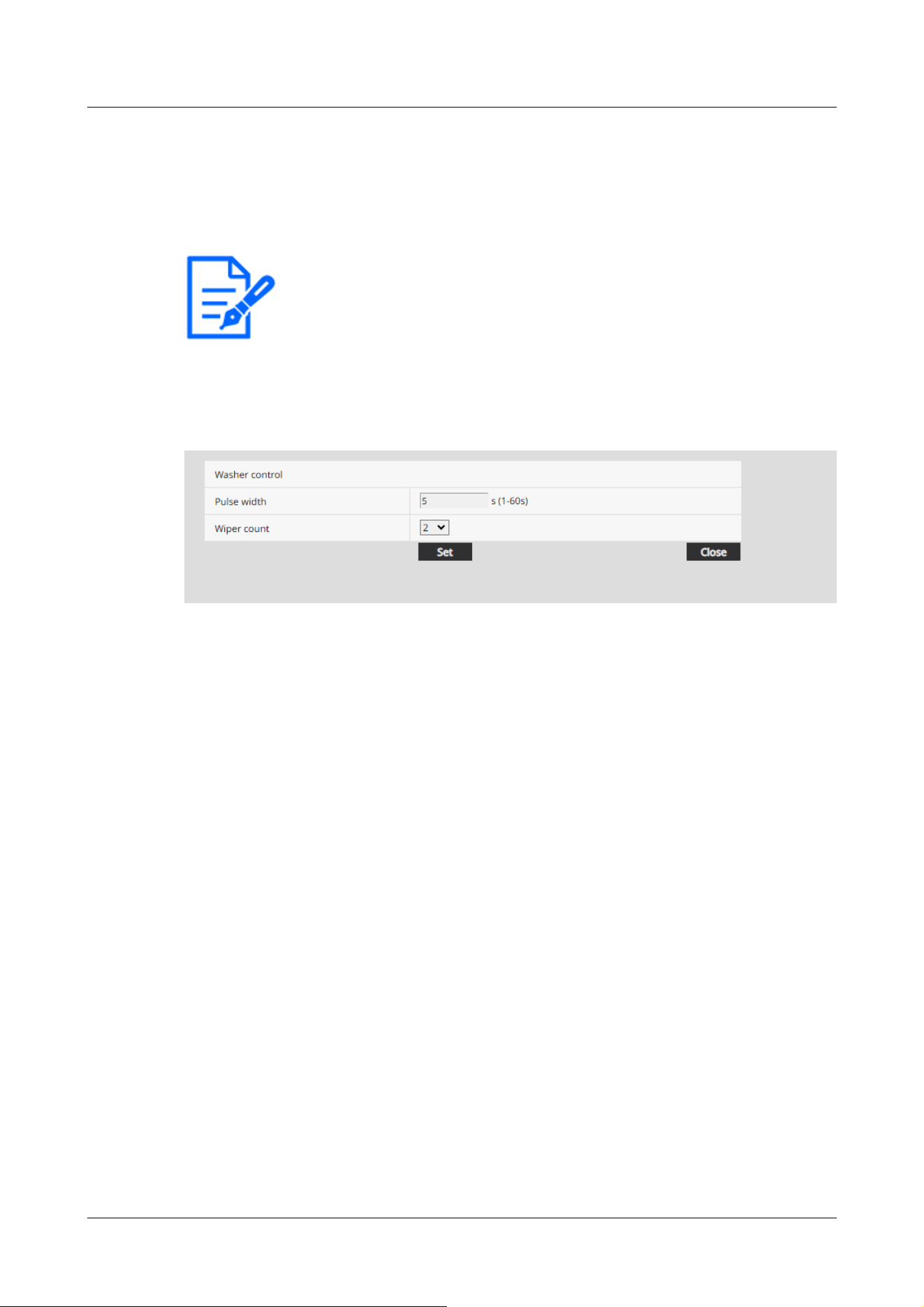
[Note:]
・[Aero PTZ] The [Relay output] can only be selected for the Aero PTZ cameras
settings.
・For the "-" and "+" relay pins, refer to the installation manual of the model.
displayed in the item. For details on how to set the screen displayed when clicking the link, refer
to the following.
→9.1.1 Set Washer (Washer control screen)
9.1.1 Set Washer (Washer control screen)
Set Washer control
[Pulse width]
Enter the pulse width of the washer from 1 second to 60 seconds in 1 second intervals.
Available time setting: 1 to 60
[Wiper count]
After the time for the pulse width of the wiper has completed, specify the wiper count.
Available number of counts: 0 to 10
[Close] button
Click this button to close the “Washer control” setup menu.
9.2 [SD memory card] for setting SD Memory Cards
On the Basic Page, press the [SD memory card] tab. Refer to the following how to display and
operate the Advanced menu.
→5.1 How to display
→5.2 How to operate
Here, settings for the SD Memory Card are made.
9 [Basic] for basic setup of the machine
9.2 [SD memory card] for setting SD Memory Cards
257

[Note:]
・The layout of each setting item varies depending on the model.
・Refer to the catalog specifications for the functions installed in each model.
[Note:]
・[Rapid PTZ] Refer to [Insert/Remove SD memory card mode] to install and
remove the SD Memory Card.
[Note:]
・If [Image capture mode] is set to [60fps Mode] or [50fps mode], the SD Memory
Card functions are not available. [SD memory card] is set to [Not use].
[Note:]
・For the functional extension software we sell and provide, please refer to our
technical information website<Control No. C0103>.
・It is recommended to format the SD Memory Card when setting the function
extension software mode from [On] to [Off].
・The operation of the recording function to the SD Memory Card cannot be
guaranteed when the extended software using the SD Memory Card is operated.
Operation mode
[SD memory card]
You set whether to use the SD Memory Card or not.
[Ext. software mode]
This setting is set to [On] when the installed function extension software uses the SD Memory
Card of the computer.
[On]:The function extension software can use the SD Memory Card of the computer.
[Off]:The function extension software cannot use the SD Memory Card of the computer.
[SD memory card file system type]
You can select the file system format of the SD memory card. This can be selected only when [Ext.
software mode] is [On].
[FAT(FAT16/FAT32/exFAT)]:FAT formatted SD memory cards can be used.
[ext(ext4)]:ext formatted SD memory cards can be used.
9 [Basic] for basic setup of the machine
9.2 [SD memory card] for setting SD Memory Cards
258

[Important]
・If you change [SD Memory Card File System Format], click the [Execute] button
in [Format] to format the SD memory card.
[Note:]
・When “ext(ext4)” is selected, the SD memory card can be used only with
function extension software. Therefore, you will not be able to use functions such
as recording video and audio to the SD memory card, or notification of remaining
space in the SD memory card.
・When "ext(ext4)" is selected, the past information on the SD memory card will be
deleted and cannot be displayed in the [Status] tab of the Maintenance page.
→18.3 [Status] for checking the status
・When “ext(ext4)” is selected, the capacity of the SD memory card cannot be
displayed.
→9.2 [SD memory card] for setting SD Memory Cards
→2.7 Display the log list
→2.4.2 View images from a tablet terminal
[Note:]
・If you use [Audio recording], you must set [Recording format] to streams.
[Audio recording]
You can set whether to record audio data when storing movies in MP4 format.
[Off]:Audio data is not saved in movies (MP4 format).
[On]:Audio data is saved in the movie (MP4 format).
[Remaining capacity notification]
To notify the remaining capacity of the SD Memory Card using the mail notification function or the
unique alarm notification function, select the following whether to start notification when the free
space becomes the %.
50%/ 20%/ 10%/ 5%/ 2%
9 [Basic] for basic setup of the machine
9.2 [SD memory card] for setting SD Memory Cards
259

[Note:]
・Remaining capacity notification is made for each remaining capacity value below
the set value.
For example, when set to [50%], the remaining capacity is 50%, 20%, 10%, 5%, and
2%, respectively. The timing of notification may deviate slightly.
[Important]
・If you do not want to use the SD Memory Card, set it to [Not use].
・Before removing the SD Memory Card from the computer, be sure to set it to
[Not use]. If the SD Memory Card is set to [Use], the SD Memory Card may be
damaged.
・When the SD Memory Card is set to [Use], the SD Memory Card is saved
according to the [Save trigger] setting.
・After installing the SD Memory Card, set it to [Use].
・If the image update speed is high, the timing and interval of notification and
recording may be misaligned. In addition, when multiple users receive images,
notification or recording may not be performed as set. In that case, slow down the
image update rate.
・The number of SD Memory Card rewrites is limited. If rewriting is frequent, the
life of the watch may be shortened.
・The life of the SD Memory Card is affected by the number of image files saved to
the SD Memory Card and the number of logs written.
・You can reduce the number of files saved to the SD Memory Card by selecting
the stream in [Recording format] and setting the smaller value in [Bit Rate*/
Client] of the stream to be recorded.
・If the SD Memory Card is written more frequently and the writing speed
decreases, it is recommended to replace the new SD Memory Card.
・When switching from [Off] to [On], when the free space on the SD Memory Card
is small, old images may be deleted to prepare for writing.
[Overwrite]
You set whether to overwrite and save images when the free space on the SD Memory Card is
running low.
[On]:If the free space on the SD Memory Card decreases, the old image is overwritten and saved
repeatedly.
[Off]:If the SD Memory Card has no free space, the SD Memory Card stops storing data.
9 [Basic] for basic setup of the machine
9.2 [SD memory card] for setting SD Memory Cards
260

SD Memory Card security setting
[Additional info for detecting alteration]
Set whether to add information to enable detection when data on the SD Memory Card is falsified.
Falsification detection supports only video (MP4 format) and can be checked using dedicated
software.
Please refer to our Technical Information Website provides specific software for tampering
detection and how to use it.<Control No. C0304>.
To Advanced Settings>>Click the [button] to display the setting window for adding falsification
detection information in a separate window.
→9.3 [Alteration detection] for detecting tampering
[SD memory card password lock]
Set the password on the SD Memory Card. When you set the password, you cannot write to or
read from the SD Memory Card on any device other than this unit. If the SD Memory Card is
stolen or lost, the risk of leakage of the recorded data can be reduced.
[Set]
If an SD Memory Card with no password set is inserted, the password can be set using the Set
button.
[Password]/[Retype password]
Type a password.
Number of characters that can be entered:4 to 16 characters
Characters that cannot be entered:Double-byte and single-byte symbols " &
[Reset]
If an SD Memory Card with the password set has been inserted, the password can be canceled by
pressing the release button.
[Password]
Type a password.
Number of characters that can be entered:4 to 16 characters
Characters that cannot be entered:Double-byte and single-byte symbols " &
[Change]
If an SD Memory Card with the password already set is inserted, the password can be changed by
using the Change button.
[Old password]/[New password]/[Retype new password]
9 [Basic] for basic setup of the machine
9.2 [SD memory card] for setting SD Memory Cards
261

[Note:]
・The password lock function supports SDHC memory card or SDXC memory card
only.
・When using an SD Memory Card with Password lock set on a device other than
this device, release the password by pressing the Password lock release button,
and then remove the SD Memory Card from the card. You cannot cancel the
password on any device other than the camera, such as a PC.
・If the [SD memory card password lock] [Status] is [Lock] and the SD Memory
Card with no password setting is inserted into the computer, the password is
automatically set to the SD Memory Card.
[Important]
・If you forget the set password, you cannot cancel the password. Since the SD
Memory Card with the password set cannot be used, be sure to manage it carefully.
・If you forget the set password and want to replace it with a new SD Memory Card,
set the [SD memory card password lock] [Status] to [Not been set] in advance by
following one of the steps below.
Enter the password using the release button and press the set button.
-Initialize the set value from the maintenance page.
Type a password.
Number of characters that can be entered:4 to 16 characters
Characters that cannot be entered:Double-byte and single-byte symbols " &
[Status]
Displays the password lock setting status.
[During locking]:The SD Memory Card has a password and the lock function is enabled.
[Not set]:Lock function is disabled
The password setting status of the SD Memory Card is displayed.
[Password already set]:The password is set correctly.
[Error (unsupported SD memory card)]:Password lock not supported card is inserted. Check that
the SDHC Memory Card or SDXC Memory Card is inserted.
[Error (password mismatch)]:The SD Memory Card cannot be used because the password set on
the SD Memory Card and the password set on this computer do not match. Confirm the password
is correct.
[Errors (other errors)]:This message is displayed when an error occurs in the SD Memory Card.
Check the SD Memory Card.
9 [Basic] for basic setup of the machine
9.2 [SD memory card] for setting SD Memory Cards
262

[Important]
・Use an UHS-I (Ultra High Speed-I)-compatible card for the Speed Class 10 SD
Memory Card.
・It is recommended to use the microSD memory card dedicated to i-PRO devices.
・When using SD Memory Cards other than those compatible with Speed Class 10,
the bit rate of streams selected with [Recording format] should be 6144 kbps.
・When using SD Memory Cards compatible with Speed Class 10, the bit rate of
streams selected by [Recording format] should be up to 12288 kbps.
・[MULTI] The SD Memory Card cannot be used except for the Speed Class 10.
・[MULTI] The bit rate of the streams selected in [Recording format] should be up
to 4096 kbps.
[Note:]
・When [Stream] is selected, the [Stream] settings in the [Image] tabs of the video
and audio pages are [Streams].&This switches to the [Record movie] setting.
・When [Recording format] is changed to [Stream], the following functions may be
corrected.
-If [Transmission priority] is set to [Best effort], it is set to [Frame rate].
-If [Refresh interval] is set to [2s], [3s], [4s], or [5s], then it is set to [1s].
Recording stream
[Recording format]
Select the type of image data to be saved on the SD Memory Card.
[Off]:Image data is not saved.
[JPEG(1)]:Still image (JPEG(1)) is saved. Save your data according to the [JPEG(1)] Image capture
size on the [Image] tabs of the video and audio pages.
[JPEG(2)]:Still image (JPEG(2)) is saved. Save your data according to the [JPEG(2)] Image capture
size on the [Image] tabs of the video and audio pages.
[Stream(1)]:Save the movie (stream (1)) in MP4 format. Save your data according to the
[Stream(1)] settings on the [Image] tabs of the video and audio pages.
[Stream(2)]:Save the movie (stream (2)) in MP4 format. Save your data according to the
[Stream(2)] settings on the [Image] tabs of the video and audio pages.
[Stream(3)]:Save the movie (stream (3)) in MP4 format. Save your data according to the
[Stream(3)] settings on the [Image] tabs of the video and audio pages.
[Stream(4)]:Save the movie (stream (4)) in MP4 format. Save your data according to the
[Stream(4)] settings on the [Image] tabs of the video and audio pages.
9 [Basic] for basic setup of the machine
9.2 [SD memory card] for setting SD Memory Cards
263

・[Recording format] cannot be changed to [JPEG] if [On] is set to [Additional info
for detecting alteration].
・If [Recording format] is [Stream], the file to be saved is named automatically.
・If [Recording format] is [Stream], there may be fewer users that can be connected.
・If you configure [On] for [Audio recording], the maximum bit rate that can be
configured for streams is limited.
・If you configure [On] for [Additional info for detecting alteration], the maximum
bit rate that can be configured for streams is limited.
・[MULTI] If [Stream] is selected in [Recording format], the bit rate is restricted.
[Note:]
・If [Recording format] is streamed, [FTP/SFTP periodic image transmission error]
cannot be set.
・To generate an alarm, use the [Alarm] tabs to set the alarm.
・If [Recording format] is [JPEG], [Schedule] cannot be set.
[Save trigger]
Select the method below to save images on the SD Memory Card.
[FTP/SFTP periodic transmission error]:FTP/Save the image when periodic transmission to the
SFTP server fails.
This option is available only when [JPEG] is selected in [Recording format].
[Alarm input]:Saves the image when an alarm is generated.
[Manual]:Save the image manually.
[Schedule]:Save the image according to the schedule settings. This option is available only when
[Stream] is selected in [Recording format].
→17 [Schedule] for scheduling
When [Alarm input] is selected in [Save trigger], the alarm type can be selected from the following.
[Terminal 1]:The image is saved when an alarm is generated at terminal 1.
[Terminal 2]:Image is saved when alarm is generated at terminal 2.
[Terminal 3]:The image is saved when an alarm is generated at terminal 3.
[VMD]:Image is saved when operation detection occurs.
[SCD]:The image is saved when undesired detection occurs.
[Impact detection]:Image is saved when impact detection occurs.
[Casing open detection]:Image is saved when opening detection occurs.
[Auto track]:Save the image when auto tracking occurs.
[Command alarm]:Saves the image when a command alarm is entered.
9 [Basic] for basic setup of the machine
9.2 [SD memory card] for setting SD Memory Cards
264
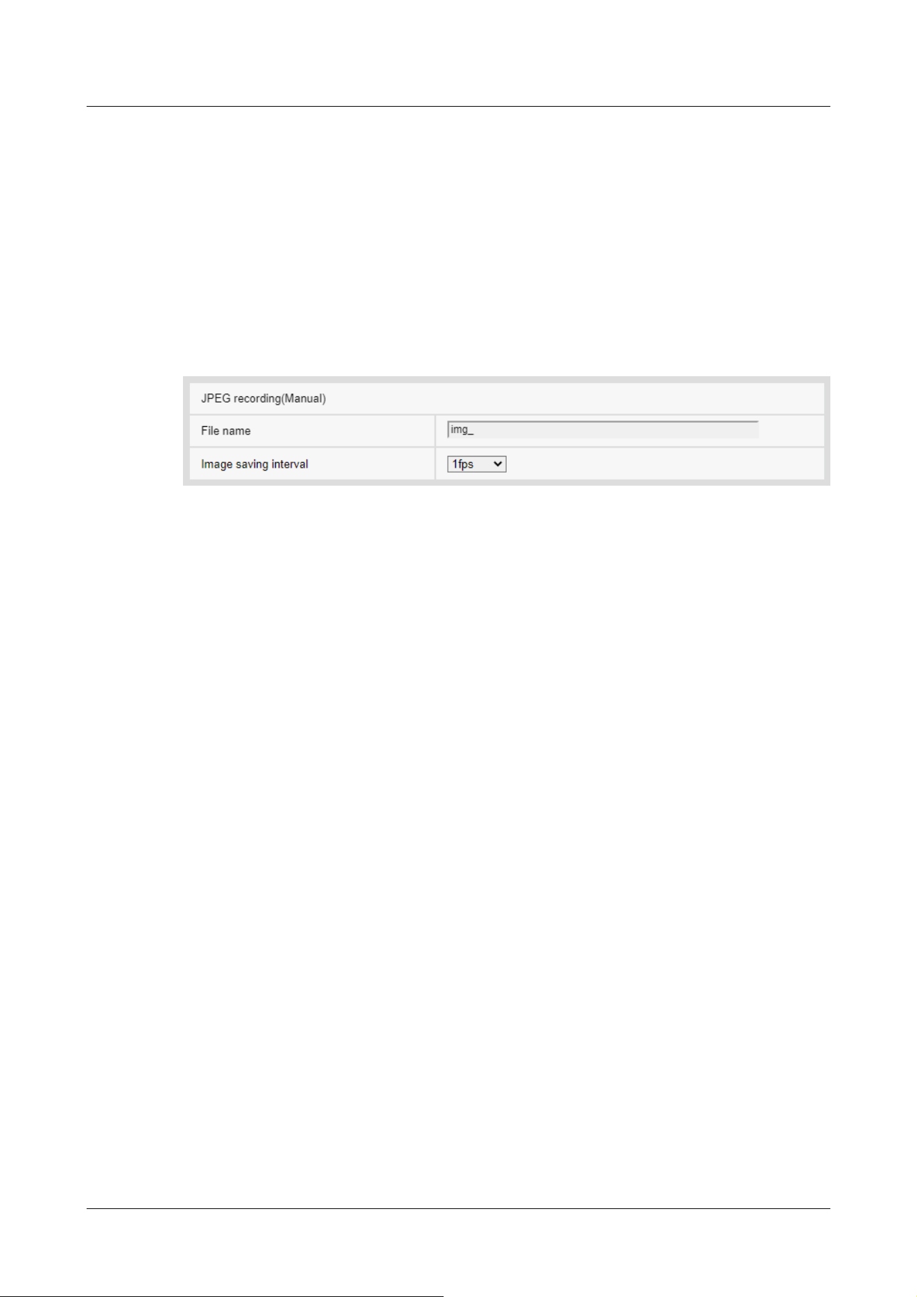
・When connected to our network disk recorder, [Save trigger] may be grayed out
by [Network failure]. To change the [Save trigger] setting after you disconnect
the recorder, set [SD memory card] to [Not use] and then set [Use] again.
・If [GOP control] is set to Advanced (Fixed GOP 60s + 1s keyframe), alarm
recording cannot be set.
・Images are not recorded when sound detection alarm is generated.
JPEG manual storage recording
This setting is available only when [Recording format] is set to [JPEG(1)] or [JPEG(2)] and [Save
trigger] is set to [Manual].
[File name]
Enter the file name for saving images to the SD Memory Card. The following file names are
actually saved.
File name:File name entered + Date and time (year, month, day, minute, second) + Sequence
number
Number of characters that can be entered:1 to 8 characters
Characters that cannot be entered:Double-byte and single-byte symbols " & * / : ; < > ? ¥ ¦
[Image saving interval]
If [Save trigger] is set to [Manual], select the interval to save images to the SD Memory Card from
the following.
When [Image capture mode] is set to 30 fps/15 fps: 0.1 fps/0.2 fps/0.33 fps/0.5 fps/1 fps
When [Image capture mode] is set to 25 fps/12.5 fps: 0.08 fps/0.17 fps/0.28 fps/0.42 fps/1 fps
JPEG recording (when alarm occurs)
9 [Basic] for basic setup of the machine
9.2 [SD memory card] for setting SD Memory Cards
265
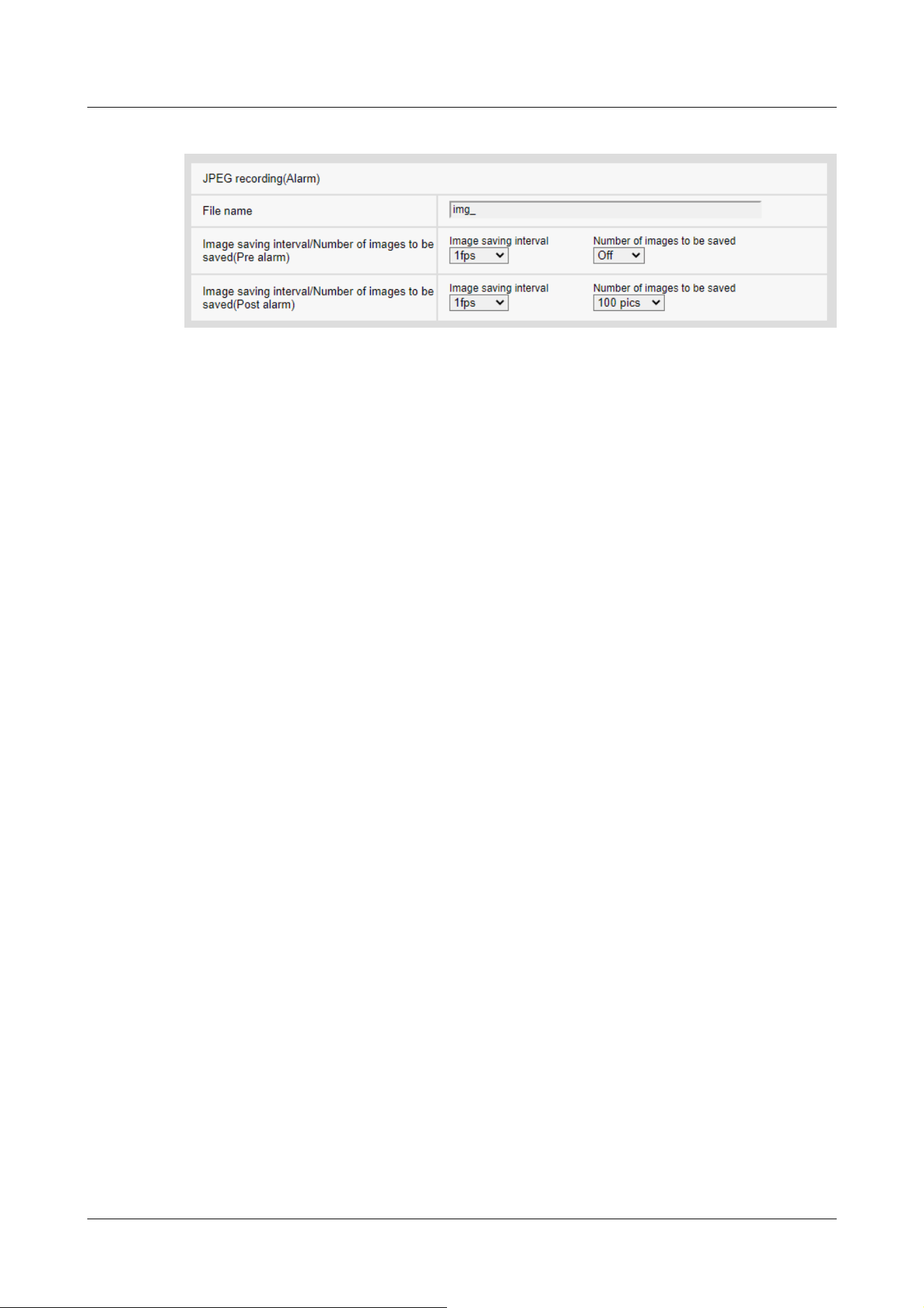
This setting is available only when [Recording format] is set to [JPEG(1)] or [JPEG(2)] and [Save
trigger] is set to [Alarm input].
[File name]
Enter the file name for saving images to the SD Memory Card. The following file names are
actually saved.
File name:File name entered + Date and time (year, month, day, minute, second) + Sequence
number
Number of characters that can be entered:1 to 8 characters
Characters that cannot be entered:Double-byte and single-byte symbols " & * / : ; < > ? ¥ ¦
[Storage interval/number of images (pre-alarm)] [Image saving interval]
When [Save trigger] is set to [Alarm input], select the pre-alarm image interval to save the image
to the SD Memory Card.
When [Image capture mode] is set to 30 fps/15 fps: 0.1 fps/0.2 fps/0.33 fps/0.5 fps/1 fps
When [Image capture mode] is set to 25 fps/12.5 fps: 0.08 fps/0.17 fps/0.28 fps/0.42 fps/1 fps
[Storage interval/number of images (pre-alarm)] [Number of images to be saved]
Select the number of pre-alarm images to be saved to the SD Memory Card when an alarm is
generated.
[Off]/[1 pic]/[2 pics]/[3 pics]/[4 pics]/[5 pics]
[Storage interval/number of images (Post alarm)] [Image saving interval]
If [Save trigger] is set to [Alarm input] or [Manual], select the intervals below to save images to
the SD Memory Card.
When [Image capture mode] is set to 30 fps/15 fps: 0.1 fps/0.2 fps/0.33 fps/0.5 fps/1 fps
When [Image capture mode] is set to 25 fps/12.5 fps: 0.08 fps/0.17 fps/0.28 fps/0.42 fps/1 fps
[Storage interval/number of images (Post alarm)] [Number of images to be saved]
9 [Basic] for basic setup of the machine
9.2 [SD memory card] for setting SD Memory Cards
266
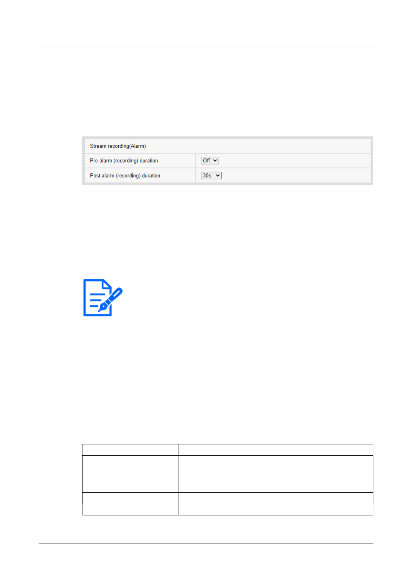
[Note:]
・The values that can be set depend on the resolution and bit rate of the stream to
be recorded. The higher the bit rate, the smaller the maximum value that can be
set as the pre-alarm time.
Within the display Description
‑‑‑‑‑‑‑‑MB/‑‑‑‑‑‑‑‑MB SD Memory Card is not inserted.
Otherwise, the remaining capacity cannot be acquired due to a
read error.
********MB/********MB SD Memory Card is not formatted.
########MB/########MB The password lock of the SD Memory Card cannot be canceled.
Select the number of alarm images to be saved to the SD Memory Card when an alarm is generated
from the following list.
[10 pics]/[20 pics]/[30 pics]/[50 pics]/[100 pics]/[200 pics]/[300 pics]/[500 pics]/[1000
pics]/[2000 pics]/[3000 pics]
Movie recording (when alarm is generated)
This setting is available only when the [Recording format] of the SD Memory Card is set to
streaming and [Save trigger] is set to [Alarm input].
[Pre alarm (recording) duration]
Select whether to record before alarm. Sets the time to save to the SD Memory Card.
[Off]/ [1s]/ [2s]/ [3s]/ [4s]/ [5s]/ [8s]/ [10s]/ [15s]/ [20s]/ [25s]/ [30s]/ [40s]/ [50s]/ [60s]/
[90s]/ [120s]
[Post alarm (recording) duration]
Sets the time to save to the SD Memory Card after an alarm is generated.
[10s]/ [20s]/ [30s]/ [40s]/ [50s]/ [60s]/ [120s]/ [180s]/ [240s]/ [300s]
*Actual recording time may be longer than the time set for the post alarm time.
SD memory card information
[Remaining capacity]
The remaining capacity and total capacity of the SD Memory Card are displayed.
Depending on the status of the SD Memory Card, it may be displayed as follows.
9 [Basic] for basic setup of the machine
9.2 [SD memory card] for setting SD Memory Cards
267

[Note:]
・When [Overwrite] is set to [Off] and the remaining capacity of the SD Memory
Card becomes [0MB], images are not saved to the SD Memory Card. When the
free space on the SD Memory Card runs out, the specified mail address and
unique alarm notification destination can be notified with the notification function.
→14.4.2 Mail sending when an alarm is generated
→14.12 [Notification] to set alarm notification
[Note:]
・When formatting an SD memory card with [ext(ext4)] selected for [SD Memory
Card File System Format], formatting may take about 20 minutes until it is
completed depending on the SD memory card.
・After formatting the SD memory card in ext format, check the operation of the
extension software using the SD memory card.
[Important]
・Prior to formatting, set [SD memory card] to [Use] on the basic pages.
→9.2 [SD memory card] for setting SD Memory Cards
・The SD Memory Card must be formatted using the [SD memory card] tabs before
using the SD Memory Card. The following functions may not work properly when
formatted outside of the [SD memory card] tabs.
-Save/retrieve image when alarm is generated
-Save/retrieve images when manually saved
-Save/retrieve images using the Schedule function
-Save/retrieve alarm log, manual/schedule save log, system log
-Saving/retrieving images using SD Memory recording function of our network
disk recorder
-Play/download images on the SD Memory Card
・When formatting is performed, the operation is interrupted if another user is
working on it.
・You cannot write to the SD Memory Card during formatting.
・When formatting is performed, all data stored on the SD Memory Card are deleted.
・Do not turn off the computer during formatting.
[Format]
To format the SD memory card, click the [Execute] button.
Format in the file format selected in [SD Memory Card File System Format].
9 [Basic] for basic setup of the machine
9.2 [SD memory card] for setting SD Memory Cards
268

・After formatting, the SD Memory Card displays less than the total amount of
space because it creates the initial directory required to operate.
・The use of an SD Memory Card for i-PRO devices is recommended.
・When recording images repeatedly on an SD Memory Card using the automatic
overwrite function, use an SD Memory Card with high reliability and durability.
・Use an UHS-I (Ultra High Speed-I)-compatible card for the SD Memory Card
that supports the speed class Class 10.
[Note:]
・[Rapid PTZ] [Insert/Remove SD memory card mode] will appear only in Rapid
PTZ Camera.
[Note:]
・[Rapid PTZ] "Now Maintenance Mode" is displayed on the image during
[Insert/Remove SD memory card mode], and functions such as pan/tilt operation
are restricted.
[Note:]
・If you use Falsification Detect, you must set [Recording format] to streaming.
Installing and removing the SD Memory Card
[Insert/Remove SD memory card mode]
To install or remove an SD Memory Card, press [Execute].
After the SD Memory Card has been installed and removed, click the [Release] button.
9.3 [Alteration detection] for detecting tampering
When the data on the SD Memory Card is falsified, the data can be detected using the dedicated
software.
Falsification detection supports only video files (MP4 format).
For information on how to set up falsification detection, please refer to the support video page of
the support site.<Control No. P0001>.
Please refer to our Technical Information Website provides specific software for tampering
detection and how to use it.<Control No. C0304>.
9 [Basic] for basic setup of the machine
9.3 [Alteration detection] for detecting tampering
269
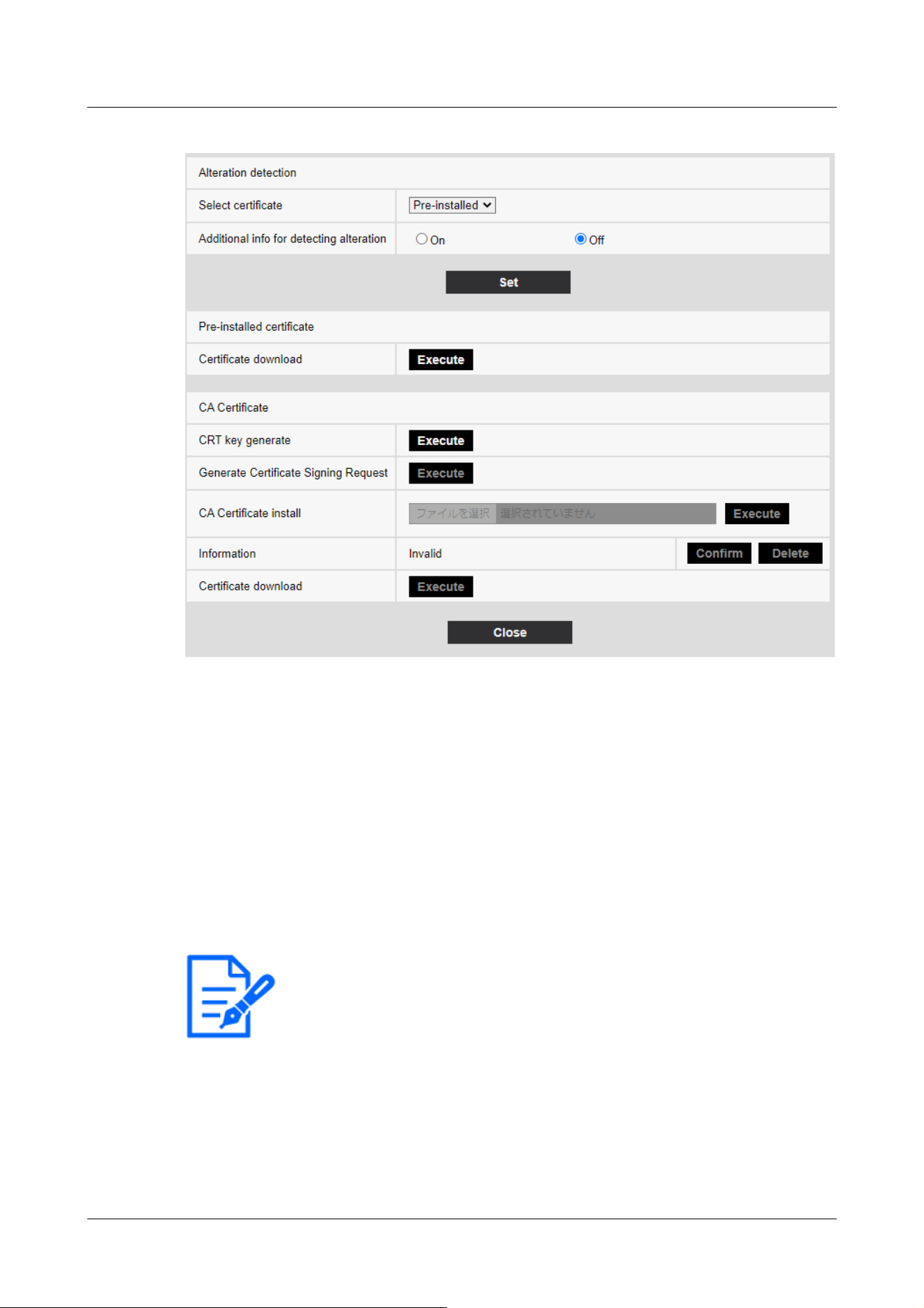
[Note:]
・If the [Recording format] of [Recording stream] is set to JPEG, the setting cannot
be changed to On.
Alteration detection
[Select certificate]
Select the certificate to use for falsification detection.
[Pre-installed]:Select the pre-installation certificate.
[CA]:Select a CA certificate. This is displayed only if the CA certificate is installed.
[Additional info for detecting alteration]
Set whether to add the information for detecting tampering to the movie file (MP4 format) to be
saved in the SD Memory Card.
Pre-installed certificate
[Certificate download]
Click the Run button to download the route certificate for the pre-installation certificate. Use the
downloaded certificate to detect falsification of movies (MP4 file) on the SD Memory Card using
9 [Basic] for basic setup of the machine
9.3 [Alteration detection] for detecting tampering
270

the dedicated software.
CA Certificate
[CRT key generate]
Creates a CRT key (encryption key) for use in falsification detection.
CRT key generation is performed in [CRT key generation dialog] displayed when [Execute] is
clicked.
[Generate Certificate Signing Request]
When using CA certificates issued by a certification authority as CA certificates for use in
tampering detection, it generates a signature request (CSR) to apply to the certification authority.
Create a signature request (CSR) by clicking on the [Execute] button. This is displayed in the
[Create Signature Request (CSR) dialog].
[CA Certificate install]
This feature installs certificates (CA certificates) issued by certification agencies and displays
information about installed certificates (CA certificates).
When [Select File] is clicked, the [Open File Dialog] is displayed. Select the certificate (CA
Certificate) file issued by the certification authority. Click [Execute] to install the certificate (CA
Certificate).
If a certificate (CA certificate) is installed, the file name of the installed certificate is displayed.
[Information]
The information of the certificate (CA certificate) issued by the certification authority is displayed.
When [Execute] is clicked, the registered contents of the installed certificate (CA certificate) are
displayed in [CA Certificate Confirmation Dialog].
Clicking [Delete] deletes the installed certificate (CA certificate).
[Certificate download]
The certificate (CA certificate) issued by the certification organization is downloaded from this
machine.
Use the downloaded certificate to detect falsification of movies (MP4 file) on the SD Memory Card
using the dedicated software.
9 [Basic] for basic setup of the machine
9.3 [Alteration detection] for detecting tampering
271

[Important]
・When deleting a valid certificate (CA certificate), make sure that you have a
backup of the certificate (CA certificate) on your PC or recording media. To
reinstall, a certificate (CA certificate) is required.
[Note:]
・The [falsification detection] setting can only be selected for models that have a
falsification detection function.
・Refer to the catalog specifications for the functions installed in each model.
[Note:]
・The [Overlay image] setting can only be selected for models that have a Overlay
image function.
・Refer to the catalog specifications for the functions installed in each model.
9.4 How to set up falsification detection
For information on how to set up falsification detection, please refer to the support video page of
the support site.<Control No. P0001>.
9.5 [Overlay image] to set overlays
The overlay image function embeds images uploaded to the computer into live images (overlay
display).
On the Basic Page, press the [Overlay image] tab. Refer to the following how to display and
operate the Advanced menu.
→5.1 How to display
→5.2 How to operate
Here, the overlay image function is set.
9 [Basic] for basic setup of the machine
9.5 [Overlay image] to set overlays
272
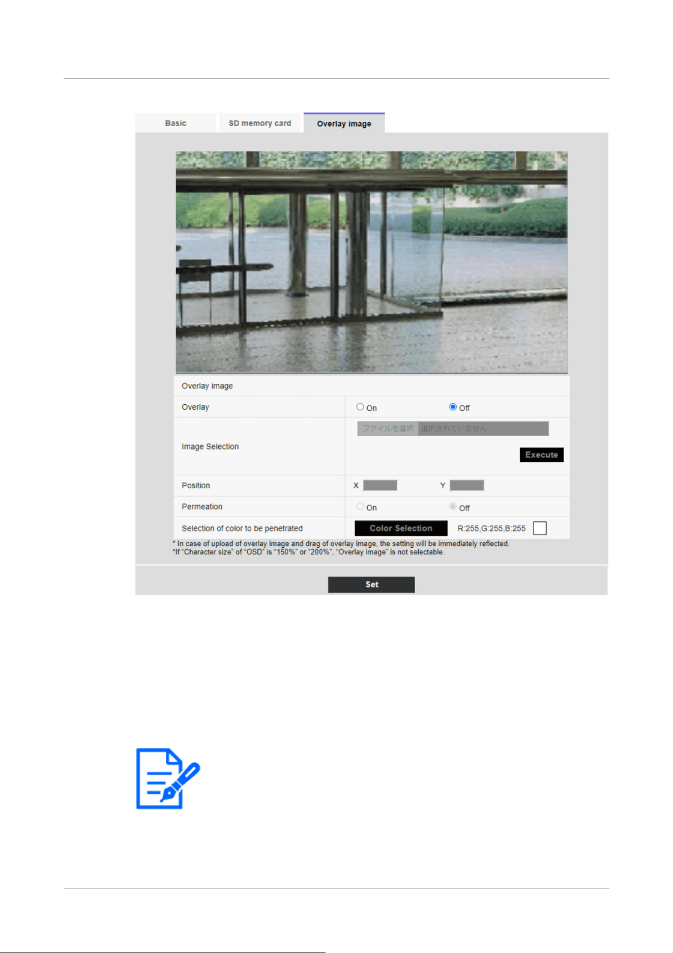
[Note:]
・[MULTI] [Camera selection] can be selected only for Multi-directional cameras.
[Overlay image]
Select the camera for which you want to set the overlay.
[Camera 1]:Sets camera 1 overlay.
[Camera 2]:Sets camera 2 overlay.
[Camera 3]:Set the camera 3 overlay.
[Camera 4]:Set the camera 4 overlay.
[Overlay]
9 [Basic] for basic setup of the machine
9.5 [Overlay image] to set overlays
273

[Note:]
・If [[Character size]] is set to [150%] or [200%] for [Characters in Date/Time
Screen], [Overlay] cannot be set.
・[New X Fixed][AI Outdoor IR BulletX] If [Image capture mode] is set to [60fps
Mode] or [50fps Mode], [Overlay] cannot be set.
・Refer to the catalog specifications for the functions installed in each model.
[Note:]
・Save the image file in a folder that does not use space or double-byte characters.
You may not be able to upload files saved in spaces or folders using double-byte
characters.
[Important]
・Do not turn off the computer or operate the machine during upload of the image
file.
・The uploaded image displayed is reduced depending on the resolution of the live
image. The image quality of the uploaded image may deteriorate and be displayed.
Check the image overlaid on the live image page.
・The uploaded image is saved when uploaded.
Use [On] or [Off] to set whether the uploaded images are overlaid or not.
[On]:Displays the overlay. When set to [On], overlaid images are recorded during recording on
the SD Memory Card.
[Off]:Overlay is not displayed.
[Image Selection]
Follow the procedure below to upload an overlay image file to the computer.
1)Click the [Select File] button to select the image file saved in the PC.
2)Click [Execute] to upload the selected image files to the computer. When an image file is
uploaded, the uploaded image (uploaded image) is displayed as an overlay on the setting screen.
You can use image files with the following specifications for overlay display:
・Image format: 256 color bitmap (BMP: Windows format)
・Image size: 24 pixels x 24 pixels to 512 pixels x 512 pixels
・File capacity: 257 Kbytes or less
[Position]
The uploaded image display position (upper left corner of the image) is displayed with [X] and [Y]
9 [Basic] for basic setup of the machine
9.5 [Overlay image] to set overlays
274
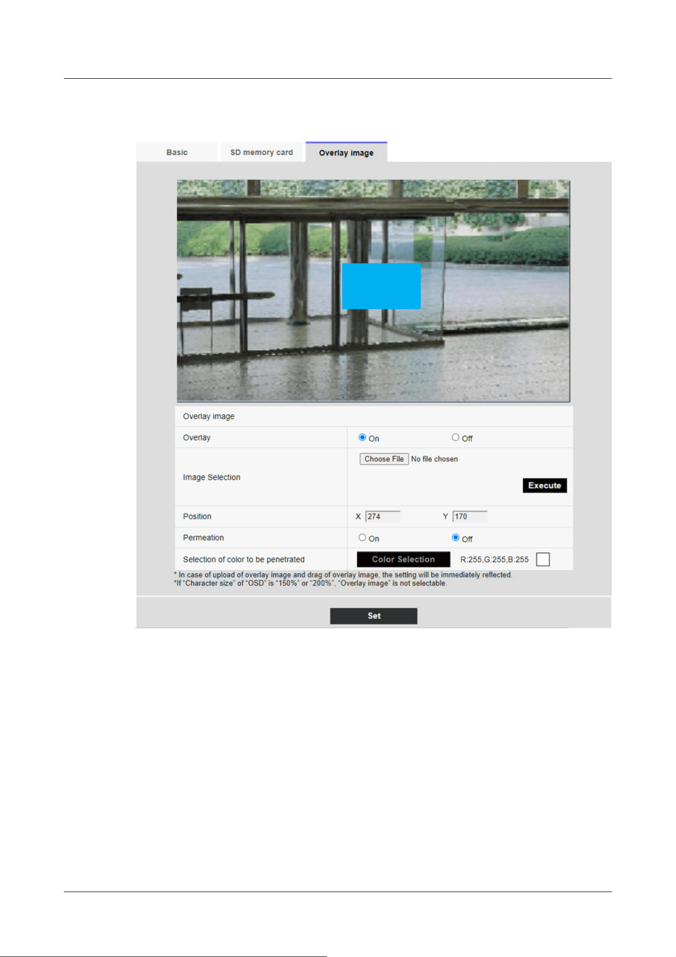
coordinates.
There are two ways to change the display position of uploaded images.
・Drag and drop the uploaded image displayed by using the mouse.
・Enter the coordinates for [X] and [Y] and press [Set].
Input digits:
-If [Image capture mode] is [16:9 mode]
X: 0 to 639, minus the size next to the uploaded image
Y: 0 to 359, minus the vertical size of the uploaded image
-If [Image capture mode] is [4:3 mode]
X: 0 to 639, minus the size next to the uploaded image
Y: 0 to 479, minus the vertical size of the uploaded image
9 [Basic] for basic setup of the machine
9.5 [Overlay image] to set overlays
275
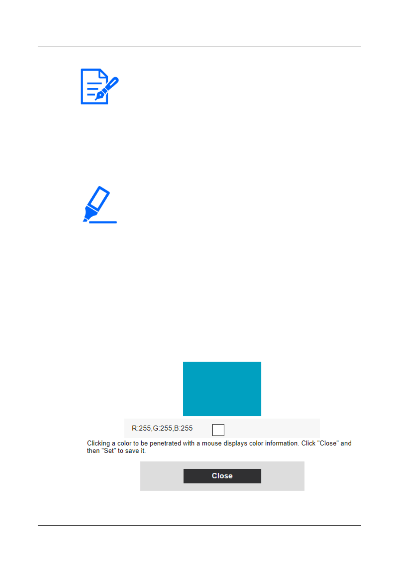
[Note:]
・You can change the display position by moving the red frame displayed when
dragging the uploaded image.
・Coordinates for displaying uploaded images to protrude from the top of the setting
screen cannot be set.
・When uploaded images are moved by the mouse, the display position is saved
without clicking the [Set] button.
・Even if you move the uploaded image to the edge of the screen, there may be a
gap between the image and the edge of the screen.
[Important]
・After changing the [Image capture mode] settings, check the position of the
uploaded images. If the display position is misaligned, set the display position
again. If the uploaded image is displayed out of the setting screen, the display
position returns to the initial value (center of the live image).
[Permeation]
Use [On] or [Off] to set whether or not the selected colors are transmitted by [Selection of color
to be penetrated].
[On]:Transmits colors selected in [Selection of color to be penetrated].
[Off]:The colors selected in [Selection of color to be penetrated] are not transmitted.
[Selection of color to be penetrated]
Select the color to be transmitted as shown below.
1 Clicking [Color Selection] displays the sub-window with the uploaded images.
9 [Basic] for basic setup of the machine
9.5 [Overlay image] to set overlays
276

2 Click the color to be transmitted in the displayed image. The selected color and RGB values
are displayed.
3 Close the sub-window by clicking [Close].
4 Finally, clicking on the [Set] will transparent the selected colors.
9 [Basic] for basic setup of the machine
9.5 [Overlay image] to set overlays
277

[Note:]
・The items that can be set differ depending on the function of the model.
・Refer to the catalog specifications for the functions installed in each model.
Model Image capture mode
Rapid PTZ camera (X/S series, Image capture
size: 2MP), Multi-directional + PTZ (PTZ part),
Aero PTZ cameras (Image capture size: 2MP)
16:9 mode(30fps mode)
16:9 mode(25fps mode)
16:9 mode(60fps mode)
16:9 mode(50fps mode)
4:3 mode(15fps mode)
4:3 mode(12.5fps mode)
4:3 mode(30fps mode)
4:3 mode(25fps mode)
Rapid PTZ Camera(X/S Series, Image capture
size: 8M (4K)), Rapid PTZ Camera(X/S Series,
Image capture size: 6MP), Indoor PTZ cameras,
Aero PTZ cameras (Image capture size: 8M (4K)),
16:9 mode(30fps mode)
16:9 mode(25fps mode)
10 [Image/Audio] for setting images and sound files
Image/audio pages configure JPEG images, H.265 images and H.264 images, and set image quality
and sound.
Video/Audio pages consist of the [Image], [Image quality], and [Audio] tabs.
10.1 [Image] to set the imaging modes
Click the [Image] tabs on the video pages. Refer to the following how to display and operate the
Advanced menu.
→5.1 How to display
→5.2 How to operate
[Image capture mode]
Select the image to be displayed on the live image, etc.
10 [Image/Audio] for setting images and sound files
10.1 [Image] to set the imaging modes
278

AI Outdoor IR Bullet Camera (S series, Image
capture size: 8MP)
Multi-directional cameras (8-megapixel models) 8 megapixels [16:9](15 fps mode)
8 megapixels [16:9](12.5 fps mode)
8 megapixels [16:9](15 fps Dual mode)
8 megapixels [16:9](12.5 fps Dual mode)
Multi-directional camera (5-megapixel model) 5 megapixels [16:9](15fps mode)
5 megapixels [16:9](12.5fps mode)
5 megapixels [16:9](15fps Quad mode)
5 megapixels [16:9](12.5fps Quad mode)
5 megapixels [4:3](15fps mode)
5 megapixels [4:3](12.5fps mode)
5 megapixels [4:3](15fps Quad mode)
5 megapixels [4:3](12.5fps Quad mode)
Multi-directional camera (4-megapixel model) 4 mega pixel [16:9](30fps mode)
4 mega pixel [16:9](25fps mode)
4 mega pixel [16:9](30fps Dual mode)
4 mega pixel [16:9](25fps Dual mode)
Compact Dome cameras (X/S series, Image
capture size: 4MP)
Compact Dome cameras (U series, Image capture
size: 4MP)
16:9 mode(30fps mode)
16:9 mode(25fps mode)
16:9 mode(2688x1520 30fps mode)
16:9 mode(2688x1520 25fps mode)
4:3 mode(15fps mode)
4:3 mode(12.5fps mode)
4:3 mode(30fps mode)
4:3 mode(25fps mode)
Compact Dome cameras (X/S series, Image
capture size: 2MP), AI Outdoor IR Bullet Camera
(S series, Image capture size: 2MP)
16:9 mode(30fps mode)
16:9 mode(25fps mode)
16:9 mode(60fps mode)
16:9 mode(50fps mode)
4:3 mode(15fps mode)
4:3 mode(12.5fps mode)
4:3 mode(30fps mode)
4:3 mode(25fps mode)
Compact Dome cameras (U series, Image capture
size: 2MP), AI Outdoor IR Bullet Camera (S
series, Image capture size: 5MP), U-series
camera with edge AI (Image capture size: 2MP)
16:9 mode(30fps mode)
16:9 mode(25fps mode)
4:3 mode(30fps mode)
4:3 mode(25fps mode)
New X Fixed Cameras (Image capture size: 2MP), 16:9 mode(30fps mode)
10 [Image/Audio] for setting images and sound files
10.1 [Image] to set the imaging modes
279

AI Outdoor IR Bullet Camera (X series, Image
capture size: 2MP)
16:9 mode(25fps mode)
16:9 mode(60fps mode)
16:9 mode(50fps mode)
4:3 mode(30fps mode)
4:3 mode(25fps mode)
4:3 mode(60fps mode)
4:3 mode(50fps mode)
New X Fixed Cameras (Image capture size: 5MP),
AI Outdoor IR Bullet Camera (X series, Image
capture size: 5MP)
16:9 mode(30fps mode)
16:9 mode(25fps mode)
16:9 mode(60fps mode)
16:9 mode(50fps mode)
4:3 mode(30fps mode)
4:3 mode(25fps mode)
4:3 mode(60fps mode)
4:3 mode(50fps mode)
New X Fixed Cameras (Image capture size: 6MP) 16:9 mode(30fps mode)
16:9 mode(25fps mode)
16:9 mode(60fps mode)
16:9 mode(50fps mode)
New X Fixed Cameras (Image capture size: 8MP),
AI Outdoor IR Bullet Camera (X series, Image
capture size: 8MP)
16:9 mode(30fps mode)
16:9 mode(25fps mode)
16:9 mode(60fps mode)
16:9 mode(50fps mode)
Corner cameras 16:9 mode(30fps mode)
16:9 mode(25fps mode)
4:3 mode(30fps mode)
4:3 mode(25fps mode)
U-series camera with edge AI (Image capture
size: 5MP)
16:9 mode(30fps mode)
16:9 mode(25fps mode)
4:3 mode(15fps mode)
4:3 mode(12.5fps mode)
4:3 mode(30fps mode)
4:3 mode(25fps mode)
U-series camera with edge AI (Image capture
size: 8MP)
16:9 mode(15fps mode)
16:9 mode(12.5fps mode)
10 [Image/Audio] for setting images and sound files
10.1 [Image] to set the imaging modes
280

[Important]
・If you change the image pickup mode setting with the following area setting, the
position will be misaligned. Therefore, after setting the imaging mode, set each
area.
-Mask area
→10.4.2 Set the mask area
-Privacy zone
→10.4.6 Setting the privacy zone (Privacy zone setting screen)
-VMD area
→14.6 [VMD area] to set the motion detection area
-SCD area
→14.8 [SCD area] to set up SCD area
-VIQS area
→10.4.8 Set up the VIQS area
-overlay image
→9.5 [Overlay image] to set overlays
・The [16:9 mode(60fps mode)]/[16:9 mode(50fps mode)]/[4:3 mode(15fps
mode)]/[4:3 mode(12.5fps mode)] imaging modes do not allow the use of advanced
features or autotracking features.
・[MULTI] If a slow shutter mode is set during operation, such as at night, it may
take a lot of time to complete the setting.
・[New X Fixed][AI Outdoor IR BulletX] If [Stabilizer] is set to [On] when [16:9
mode(60fps mode)]/[16:9 mode(50fps mode)]/[4: 3 mode (60fps mode)]/[4: 3
mode (50fps mode)] is set to Image capture mode, it is changed to [Off].If so, a
reboot will be performed.
[Note:]
・If the VIQS area is enabled, make sure that the VIQS settings do not exceed the
maximum range after changing the aspect ratio from [4:3] to [16:9].
・In 2 megapixels [16:9] (60 fps mode), when multiple streams are delivered, 60 fps
delivery is not possible and the image may be displayed intermittently. If the voice
is simultaneously delivered, the data will be delivered at 30 fps.
For other terms and conditions regarding stream delivery, please refer to our
technical information website.<Control No. C0309>.
10 [Image/Audio] for setting images and sound files
10.1 [Image] to set the imaging modes
281

[Note:]
・Selecting JPEG enables you to select the update interval.
MJPEG/ [Refresh interval : 1s]/[Refresh interval : 3s]/[Refresh interval :
5s]/[Refresh interval : 10s]/[Refresh interval : 30s]/[Refresh interval : 60s]
・The streams can be selected when [Stream transmission] is [On].
・[MULTI] When [4 image display JPEG]/[3 image display JPEG] is selected,
[Refresh interval : 1s] [Still image update: 3 seconds] cannot be selected.
・[MULTI] Select [4 image display stream (2)], [3 image display stream (2)], [4
image display JPEG], or [3 image display JPEG] to select the following display
method.
]
.
]
10.2 [Image] for setting JPEG images
Click on the [Image] tabs of the video and audio pages. Refer to the following how to display and
operate the Advanced menu.
→5.1 How to display
→5.2 How to operate
Live image (initial display)
Here, the default setting to be displayed on the live picture is performed.
[Initial display stream]
Select the images to be displayed in Live image pages from the following.
Compact camera(U series)
JPEG(1)/ JPEG(2)/ [Stream(1)]/[Stream(2)]/[Stream(3)]/[Stream(4)]
Rapid PTZ Cameras, Indoor PTZ cameras, Aero PTZ cameras, Compact camera(S series), New X
fixed camera, Corner cameras, AI Outdoor IR Bullet Camera, U-series camera with edge AI
JPEG(1)/ JPEG(2)/ [Stream(1)]/[Stream(2)]/[Stream(3)]/[Stream(4)]/[Multi-screen]
Multi-directional + PTZ (PTZ part)
JPEG(1)/ JPEG(2)/ [Stream(1)]/[Stream(2)]/[Stream(3)]/[Stream(4)]/[Multi-sensor + PTZ]
Multi-directional cameras
[4 image display stream(2)], [3 image display stream(2)], [2 image display stream(2)], [4 image
display JPEG], [3 image display JPEG], [2 image display JPEG], [2 image display JPEG], [2 image
display 1 stream(1)], [Camera 1 stream(2)], [Camera 1 JPEG], [Camera 2 stream(1)], [Camera 2
stream(2)], [Camera 2 JPEG], [Camera 3 stream(1)], [Camera 3 stream(2)], [Camera 3 JPEG],
[Camera 4 stream(1)], [Camera 4 stream(2)], [Camera 4 JPEG]/[Camera 4 JPEG]/ [Multi-sensor
+ PTZ]
10 [Image/Audio] for setting images and sound files
10.2 [Image] for setting JPEG images
282

[4 split]/[360 deg.]
[3 split]/[270 deg.]
・[MULTI] Four-image display is available for the four-eye model.
・[MULTI] Three-image display is available for the three-eye model.
・[MULTI_PTZ] Only Multi-directional/PTZ-integrated cameras can be selected
for [Multi-directional + PTZ].
[Note:]
・If [Stream transmission] is set to [On] and the value with [*] is set, the image
updating rate may be lower than the set value. The value with [*] depends on the
model. Refer to this item on the detailed camera setting screen for the relevant
parameters.
・The [*] option is omitted.
・Depending on the network environment, resolution, image quality, number of
simultaneous accesses, etc., the image update rate may be lower than the set
value.
・If the image is not delivered at the set image update rate, you can reduce the
resolution and image quality to close to the set value.
・The updating speed up to the value of the selected imaging mode can be selected.
[JPEG image updating speed (movie)*]
Select the rate at which the JPEG image is updated.
If [Image capture mode] is set to [Single source [4:3](30fps mode)]/[Dual sources [4:3](15fps
mode)]/[60fps mode]:
0.1fps/ 0.2fps/ 0.33fps/ 0.5fps/ 1fps/2fps/ 3fps/ 5fps/ 6fps/ 10fps/ 12fps/ 15fps/ 30fps
If [Image capture mode] is set to [Single source [4:3](25fps mode)]/[Dual sources [4:3](12.5fps
mode)]/[50fps mode]:
0.08fps/ 0.17fps/ 0.28fps/ 0.42fps/ 1fps/ 2.1fps/ 3.1fps/ 4.2fps/ 5fps/ 8.3fps/ 12.5fps/ 25fps
JPEG
Here, the [Image capture size] [Image quality] of JPEG is set. For settings for H.265 (or H.264)
images, see below.
→10.3 [Image] for setting up streams
10 [Image/Audio] for setting images and sound files
10.2 [Image] for setting JPEG images
283

[Note:]
・[MULTI] This setting is common to all cameras.
・[New X Fixed-8M][New X Fixed-6M][New X Fixed-5M][AI Outdoor IR
BulletX-8M][AI Outdoor IR BulletX-5M] If [Image capture mode] is set to [60fps
mode] or [50fps mode], [JPEG1][JPEG2] cannot be used.
Aircraft type Image capture mode JPEG1 JPEG2
New X Fixed Cameras
(Image capture size:
2MP)
16:9 mode(30fps mode)
16:9 mode(25fps mode)
16:9 mode(60fps mode)
16:9 mode(50fps mode)
1920x1080
1280x720
640x360 640x360
320x180
4:3 mode(30fps mode)
4:3 mode(25fps mode)
4:3 mode(60fps mode)
4:3 mode(50fps mode)
2048x1536
1280x960
640x480 640x480
320x240
New X Fixed Cameras
(Image capture size:
5MP)
16:9 mode(30fps mode)
16:9 mode(25fps mode)
Only the same
Image capture size
set for stream (1),
stream (2), stream
(3) and JPEG (2)
can be selected.
640x360
16:9 mode(60fps mode)
16:9 mode(50fps mode)
- -
4:3 mode(30fps mode)
4:3 mode(25fps mode)
Only the same
Image capture size
set for stream (1),
stream (2), stream
(3) and JPEG (2)
can be selected.
640x480
[Image capture size]
When displaying a JPEG image, select the Image capture size of the image to be displayed.
Please refer to the following for the relationship between your model and symbols and terminology.
→1.2 Compatible models and symbols in this manual
New X fixed camera
10 [Image/Audio] for setting images and sound files
10.2 [Image] for setting JPEG images
284

4:3 mode(60fps mode)
4:3 mode(50fps mode)
- -
New X Fixed Cameras
(Image capture size:
6MP)
16:9 mode(30fps mode)
16:9 mode(25fps mode)
Only the same
Image capture size
set for stream (1),
stream (2), stream
(3) and JPEG (2)
can be selected.
640x360
16:9 mode(60fps mode)
16:9 mode(50fps mode)
- -
New X Fixed Cameras
(Image capture size:
8MP)
16:9 mode(30fps mode)
16:9 mode(25fps mode)
Only the same
Image capture size
set for stream (1),
stream (2), stream
(3) and JPEG (2)
can be selected.
640x360
16:9 mode(60fps mode)
16:9 mode(50fps mode)
- -
Aircraft type Image capture mode JPEG1 JPEG2
Compact camera
(X/S series, Image
capture size: 4MP)
16:9 mode(30fps mode)
16:9 mode(25fps mode)
Only the same
Image capture size
set for stream (1),
stream (2), stream
(3) and JPEG (2)
can be selected.
640x360
16:9 mode(2688x1520 30fps mode)
16:9 mode(2688x1520 25fps mode)
Only the same
Image capture size
set for stream (1),
stream (2), stream
(3) and JPEG (2)
can be selected.
640x360
4:3 mode(30fps mode)
4:3 mode(25fps mode)
1280x960
640x480
320x240
640x480
Compact camera
10 [Image/Audio] for setting images and sound files
10.2 [Image] for setting JPEG images
285

4:3 mode(15fps mode)
4:3 mode(12.5fps mode)
2048x1536
1280x960
640x480
320x240
640x480
Compact camera
(X/S series, Image
capture size: 2MP)
16:9 mode(30fps mode)
16:9 mode(25fps mode)
1920x1080
1280x720
640x360
320x180
640x360
16:9 mode(60fps mode)
16:9 mode(50fps mode)
1920x1080
1280x720
640x360
320x180
640x360
4:3 mode(30fps mode)
4:3 mode(25fps mode)
1280x960
640x480
320x240
640x480
4:3 mode(15fps mode)
4:3 mode(12.5fps mode)
2048x1536
1280x960
640x480
320x240
640x480
Compact camera
(U series, Image
capture size: 4MP)
16:9 mode(30fps mode)
16:9 mode(25fps mode)
Only the same
Image capture size
set for stream (1),
stream (2), stream
(3) and JPEG (2)
can be selected.
640x360
16:9 mode(2688x1520 30fps mode)
16:9 mode(2688x1520 25fps mode)
2688x1520
1920x1080
1280x720
640x360
640x360
4:3 mode(30fps mode)
4:3 mode(25fps mode)
1280x960
640x480
320x240
640x480
4:3 mode(15fps mode)
4:3 mode(12.5fps mode)
2048x1536
1280x960
640x480
320x240
640x480
10 [Image/Audio] for setting images and sound files
10.2 [Image] for setting JPEG images
286

Compact camera
(U series, Image
capture size: 2MP)
16:9 mode(30fps mode)
16:9 mode(25fps mode)
1920x1080
1280x720
640x360
320x180
640x360
4:3 mode(30fps mode)
4:3 mode(25fps mode)
1280x960
640x480
320x240
640x480
Aircraft type Image capture mode JPEG1 JPEG2
Corner cameras 16:9 mode(30fps mode)
16:9 mode(25fps mode)
Only the same
Image capture size
set for stream (1),
stream (2), stream
(3), stream (4) and
JPEG (2) can be
selected.
640x360
4:3 mode(30fps mode)
4:3 mode(25fps mode)
Only the same
Image capture size
set for stream (1),
stream (2), stream
(3), stream (4) and
JPEG (2) can be
selected.
VGA
Aircraft type Image capture mode JPEG1 JPEG2
AI Outdoor IR Bullet
Camera
(X series, Image
capture size: 8MP)
16:9 mode(30fps mode)
16:9 mode(25fps mode)
Only the same
Image capture size
set for stream (1),
stream (2), stream
(3) and JPEG (2)
can be selected.
640x360
16:9 mode(60fps mode)
16:9 mode(50fps mode)
- -
Corner cameras
AI Outdoor IR Bullet Camera
10 [Image/Audio] for setting images and sound files
10.2 [Image] for setting JPEG images
287

AI Outdoor IR Bullet
Camera
(X series, Image
capture size: 5MP)
16:9 mode(30fps mode)
16:9 mode(25fps mode)
Only the same
Image capture size
set for stream (1),
stream (2), stream
(3) and JPEG (2)
can be selected.
640x360
16:9 mode(60fps mode)
16:9 mode(50fps mode)
- -
4:3 mode(30fps mode)
4:3 mode(25fps mode)
Only the same
Image capture size
set for stream (1),
stream (2), stream
(3) and JPEG (2)
can be selected.
VGA
4:3 mode(60fps mode)
4:3 mode(50fps mode)
- -
AI Outdoor IR Bullet
Camera
(X series, Image
capture size: 2MP)
16:9 mode(30fps mode)
16:9 mode(25fps mode)
16:9 mode(60fps mode)
16:9 mode(50fps mode)
1920x1080
1280x720
640x360 640x360
320x180
4:3 mode(30fps mode)
4:3 mode(25fps mode)
4:3 mode(60fps mode)
4:3 mode(50fps mode)
2048x1536
1280x960
640x480 VGA
320x240
AI Outdoor IR Bullet
Camera
(S series, Image
capture size: 8MP)
16:9 mode(30fps mode)
16:9 mode(25fps mode)
Only the same
Image capture size
set for stream (1),
stream (2), stream
(3) and JPEG (2)
can be selected.
640x360
AI Outdoor IR Bullet
Camera
(S series, Image
capture size: 5MP)
16:9 mode(30fps mode)
16:9 mode(25fps mode)
Only the same
Image capture size
set for stream (1),
stream (2), stream
(3) and JPEG (2)
can be selected.
640x360
10 [Image/Audio] for setting images and sound files
10.2 [Image] for setting JPEG images
288

4:3 mode(30fps mode)
4:3 mode(25fps mode)
Only the same
Image capture size
set for stream (1),
stream (2), stream
(3) and JPEG (2)
can be selected.
VGA
AI Outdoor IR Bullet
Camera
(S series, Image
capture size: 2MP)
16:9 mode(30fps mode)
16:9 mode(25fps mode)
16:9 mode(60fps mode)
16:9 mode(50fps mode)
1920x1080
1280x720
640x360 640x360
320x180
4:3 mode(30fps mode)
4:3 mode(25fps mode)
1280x960
VGA VGA
QVGA
4:3 mode(15fps mode)
4:3 mode(12.5fps mode)
2048x1536
1280x960
VGA VGA
QVGA
Aircraft type Image capture mode JPEG1 JPEG2
U-series camera with
edge AI (Image
capture size: 8MP)
16:9 mode(15fps mode)
16:9 mode(12.5fps mode)
Only the same
Image capture size
as configured in
stream (1), stream
(2), stream (3),
stream (4), and
JPEG (2) can be
selected.
640x360
U-series camera with
edge AI (Image
16:9 mode(30fps mode)
16:9 mode(25fps mode)
Only the same
Image capture size
U-series camera with edge AI
10 [Image/Audio] for setting images and sound files
10.2 [Image] for setting JPEG images
289

capture size: 5MP) as configured in
stream (1), stream
(2), stream (3),
stream (4), and
JPEG (2) can be
selected.
640x360
4:3 mode(30fps mode)
4:3 mode(25fps mode)
Only the same
Image capture size
as configured in
stream (1), stream
(2), and JPEG (2)
can be selected.
VGA
4:3 mode(15fps mode)
4:3 mode(12.5fps mode)
Only the same
Image capture size
as configured in
stream (1), stream
(2), stream (3),
stream (4), and
JPEG (2) can be
selected.
VGA
U-series camera with
edge AI (Image
capture size: 2MP)
16:9 mode(30fps mode)
16:9 mode(25fps mode)
1920x1080
1280x720
640x360 640x360
320x180
4:3 mode(30fps mode)
4:3 mode(25fps mode)
1280x960
VGA VGA
QVGA
Aircraft type Image capture mode JPEG1 JPEG2
Rapid PTZ camera
(X/S series, Image
capture size: 2MP),
Multi-directional +
PTZ (PTZ part), Aero
16:9 mode(30fps mode)
16:9 mode(25fps mode)
16:9 mode(60fps mode)
16:9 mode(50fps mode)
1920x1080
1280x720
640x360 640x360
320x180
4:3 mode(30fps mode) 1280x960
PTZ cameras
10 [Image/Audio] for setting images and sound files
10.2 [Image] for setting JPEG images
290

PTZ cameras (Image
capture size: 2MP)
4:3 mode(25fps mode)
640x480 640x480
320x240
4:3 mode(15fps mode)
4:3 mode(12.5fps mode)
2048x1536
1280x960
640x480 640x480
320x240
Rapid PTZ
Camera(X/S Series,
Image capture size:
8MP (4K)), Indoor
PTZ cameras (Image
capture size: 8MP
(4K)), Aero PTZ
cameras (Image
capture size: 8MP
(4K))
16:9 mode(30fps mode)
16:9 mode(25fps mode)
3840x2160
2560x1440
1920x1080
1280x720
640x360 640x360
*1
320x180
Only the same
Image capture
size set for
stream (1),
stream (2),
stream (3),
stream (4) and
JPEG (2) can
be selected.
Rapid PTZ
Camera(X/S Series,
Image capture size:
6MP), Indoor PTZ
cameras (Image
capture size: 6MP)
16:9 mode(30fps mode)
16:9 mode(25fps mode)
3328x1872
2560x1440
1920x1080
1280x720
640x360 640x360
*1
320x180
Only the same
Image capture
size set for
stream (1),
stream (2),
stream (3),
stream (4) and
JPEG (2) can
be selected.
*1 JPEG (2) is set to [1280x720] if [640x360] is not selected for the resolution set in Streams (1),
10 [Image/Audio] for setting images and sound files
10.2 [Image] for setting JPEG images
291

Aircraft type Imaging mode JPEG1 JPEG2
Multi-directional
cameras (8-megapixel
models)
8 megapixels [16:9](15 fps mode)
8 megapixels [16:9](12.5 fps mode)
3840x2160 --
(Without
function)
2560x1440
1920x1080
1280x720
640x360
320x180
8 megapixels [16:9](15 fps Dual mode)
8 megapixels [16:9](12.5 fps Dual mode)
3840x2160
2560x1440
1920x1080
1280x720
640x360
Multi-directional
camera (5-megapixel
model)
5 megapixels [16:9](15fps mode)
5 megapixels [16:9](12.5fps mode)
3072x1728
2560x1440
1920x1080
1280x720
640x360
320x180
5 megapixels [16:9](15fps Quad mode)
5 megapixels [16:9](12.5fps Quad mode)
3072x1728
2560x1440
1920x1080
1280x720
640x360
5 megapixels [4:3](15fps mode)
5 megapixels [4:3](12.5fps mode)
3072x2304
2560x1920
1280x960
640x480
320x240
5 megapixels [4:3](15fps Quad mode)
5 megapixels [4:3](12.5fps Quad mode)
3072x2304
2560x1920
1280x960
640x480
Multi-directional
camera (4-megapixel
model)
4 mega pixel [16:9](30fps mode)
4 mega pixel [16:9](25fps mode)
2688x1520
2560x1440
1920x1080
1280x720
640x360
Streams (2), Streams (3), Streams (4), and JPEG (1) and four resolutions are set.
Multi-directional camera
10 [Image/Audio] for setting images and sound files
10.2 [Image] for setting JPEG images
292

320x180
4 mega pixel [16:9](30fps Dual mode)
4 mega pixel [16:9](25fps Dual mode)
2688x1520
2560x1440
1920x1080
1280x720
640x360
[Note:]
・If you set [Stream transmission] to [On], you can view both H.265 (or H.264) and
JPEG images on live picture pages.
・If one of the streams' [Stream transmission] is set to [On], the image update rate
[Image quality]
Set the quality of JPEG images at each resolution.
[0 Super fine]/[1 Fine]/2/ 3/ 4/ [5 Normal]/6/ 7/ 8/ [9 Low]
10.3 [Image] for setting up streams
Click on the [Image] tabs of the video and audio pages. Refer to the following how to display and
operate the Advanced menu.
→5.1 How to display
→5.2 How to operate
Here, H.265 (or H.264) images [bit rate per client], [Image capture size], [Image quality]
Configure, for example. For the settings of the JPEG image, refer to the following.
→10.2 [Image] for setting JPEG images
Stream
A stream is a system that simultaneously delivers images with different resolution and frame rates.
The number of streams that can be delivered at the same time is expressed as the number of
streams.
The number of streams depends on the model. Refer to the catalog specifications for the number
of streams for each model.
[Stream transmission]
Use [On] or [Off] to set whether to deliver H.265 (or H.264) images.
[On]:Deliver H.265 (or H.264) images.
[Off]:The H.265 (or H.264) image is not delivered.
10 [Image/Audio] for setting images and sound files
10.3 [Image] for setting up streams
293

of the JPEG image is limited.
For information about the rate of updating JPEG images when [Stream
transmission] is set to [On], see below.
→2.3.1 View camera images
・[MULTI] If any one of the [Stream transmission] cameras is set to [On], the image
updating rate of the JPEG image is limited.
・[MULTI] This setting can be set individually by each camera.
[Note:]
・[MULTI] This setting is common to all cameras.
Aircraft type Image capture mode
H.265/H.264
Stream 1 Stream 2 Stream 3 Stream 4
New X Fixed Cameras
(Image capture size:
2MP)
16:9 mode(30fps
mode)
16:9 mode(25fps
mode)
16:9 mode(60fps
mode)
16:9 mode(50fps
mode)
1920x1080 1920x1080
1280x720 1280x720 1280x720
640x360 640x360 640x360 640x360
320x180 320x180 320x180 320x180
4:3 mode(30fps mode)
4:3 mode(25fps mode)
2048x1536
1280x960 1280x960
[Stream encoding format]
Select the compression method for the stream to be delivered.
H.265:H.265 images are delivered.
H.264:H.264 images are delivered.
[Image capture size]
Select the resolution of the H.265 (or H.264) image from the following. Selection may be limited
depending on the selected resolution.
Please refer to the following for the relationship between your model and symbols and terminology.
→1.2 Compatible models and symbols in this manual
New X Fixed Cameras
10 [Image/Audio] for setting images and sound files
10.3 [Image] for setting up streams
294

4:3 mode(60fps mode)
4:3 mode(50fps mode)
VGA VGA VGA VGA
QVGA QVGA QVGA QVGA
New X Fixed Cameras
(Image capture size:
5MP)
16:9 mode(30fps
mode)
16:9 mode(25fps
mode)
3072x1728 3072x1728
2560x1440 2560x1440
1920x1080 1920x1080
1280x720 1280x720 1280x720 1280x720
640x360 640x360 640x360
320x180 320x180 320x180
16:9 mode(60fps
mode)
16:9 mode(50fps
mode)
3072x1728 --
(Without
function)
--
(Without
function)
--
(Without
function)
2560x1440
4:3 mode(30fps mode)
4:3 mode(25fps mode)
3072x2304 3072x2304
2560x1920 2560x1920
1280x960 1280x960
800x600
VGA VGA VGA
400x300
QVGA QVGA QVGA
4:3 mode(60fps mode)
4:3 mode(50fps mode)
3072x2304 --
(Without
function)
--
(Without
function)
--
(Without
function)
2560x1920
New X Fixed Cameras
(Image capture size:
6MP)
16:9 mode(30fps
mode)
16:9 mode(25fps
mode)
3328x1872 3328x1872
2560x1440 2560x1440
1920x1080 1920x1080
1280x720 1280x720 1280x720 1280x720
640x360 640x360 640x360
320x180 320x180 320x180
16:9 mode(60fps
mode)
16:9 mode(50fps
mode)
3328x1872 --
(Without
function)
--
(Without
function)
--
(Without
function)
2560x1440
New X Fixed Cameras
(Image capture size:
8MP)
16:9 mode(30fps
mode)
16:9 mode(25fps
mode)
3840x2160 3840x2160
2560x1440 2560x1440
1920x1080 1920x1080
1280x720 1280x720 1280x720 1280x720
640x360 640x360 640x360
320x180 320x180 320x180
10 [Image/Audio] for setting images and sound files
10.3 [Image] for setting up streams
295

16:9 mode(60fps
mode)
16:9 mode(50fps
mode)
3840x2160 --
(Without
function)
--
(Without
function)
--
(Without
function)
3840x2160
Aircraft type Image capture mode
H.265/H.264
Stream 1 Stream 2 Stream 3 Stream 4
Compact Dome cameras
(X/S Series, Image
capture size: 4MP)
16:9 mode
(2688x1520 30fps
mode)
16:9 mode
(2688x1520 25fps
mode)
2688x1520
1920x1080
1280x720
1920x1080
1280x720
640x360
320x180
640x360
320x180
--
(Without
function)
16:9 mode(30fps
mode)
16:9 mode(25fps
mode)
2560x1440
1920x1080
1280x720
1920x1080
1280x720
640x360
320x180
640x360
320x180
4:3 mode(30fps mode)
4:3 mode(25fps mode)
1280x960
640x480
320x240
1280x960
640x480
320x240
640x480
320x240
4:3 mode(15fps mode)
4:3 mode(12.5fps
mode)
2048x1536
1280x960
640x480
320x240
640x480
320x240
Compact Dome cameras
(X/S Series, Image
capture size: 2MP)
16:9 mode(60fps
mode)
16:9 mode(50fps
mode)
1920x1080
1280x720
640x360
320x180
1920x1080
1280x720
640x360
320x180
1280x720
640x360
320x180
640x360
320x180
16:9 mode(30fps
mode)
16:9 mode(25fps
mode)
1920x1080
1280x720
640x360
320x180
1920x1080
1280x720
640x360
320x180
1280x720
640x360
320x180
640x360
320x180
Compact Dome camera (X series) and Compact Dome camera (S series)
10 [Image/Audio] for setting images and sound files
10.3 [Image] for setting up streams
296
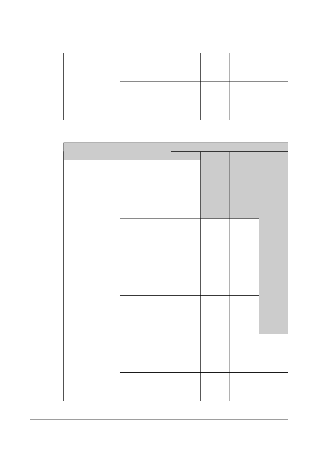
4:3 mode(30fps mode)
4:3 mode(25fps mode)
1280x960
640x480
320x240
1280x960
640x480
320x240
640x480
320x240
640x360
320x180
4:3 mode(15fps mode)
4:3 mode(12.5fps
mode)
2048x1536
1280x960
640x480
320x240
640x480
320x240
640x480
320x240
Aircraft type Image capture mode
H.265/H.264
Stream 1 Stream 2 Stream 3 Stream 4
Compact Dome cameras
(U Series, Image
capture size: 4MP)
16:9 mode
(2688x1520 30fps
mode)
16:9 mode
(2688x1520 25fps
mode)
2688x1520
1920x1080
1280x720
--
(Without
function)
--
(Without
function)
--
(Without
function)
16:9 mode(30fps
mode)
16:9 mode(25fps
mode)
2560x1440
1920x1080
1280x720
1920x1080
1280x720
640x360
320x180
640x360
320x180
4:3 mode(30fps mode)
4:3 mode(25fps mode)
1280x960
640x480
320x240
1280x960
640x480
320x240
640x480
320x240
4:3 mode(15fps mode)
4:3 mode(12.5fps
mode)
2048x1536
1280x960
640x480
320x240
640x480
320x240
Compact Dome cameras
(U Series, Image
capture size: 2MP)
16:9 mode(30fps
mode)
16:9 mode(25fps
mode)
1920x1080
1280x720
640x360
320x180
1920x1080
1280x720
640x360
320x180
1280x720
640x360
320x180
640x360
320x180
4:3 mode(30fps mode)
4:3 mode(25fps mode)
1280x960
640x480
320x240
1280x960
640x480
320x240
640x480
320x240
640x360
320x180
Compact Dome camera (U series)
10 [Image/Audio] for setting images and sound files
10.3 [Image] for setting up streams
297

Aircraft type Image capture mode
H.265/H.264
Stream 1 Stream 2 Stream 3 Stream 4
Corner cameras 16:9 mode(30fps
mode)
16:9 mode(25fps
mode)
3072x1728
2560x1440
3072x1728
2560x1440
1920x1080
1280x720
640x360
320x180
1280x720
640x360
320x180
1280x720
640x360
320x180
4:3 mode(30fps mode)
4:3 mode(25fps mode)
3072x2304
2560x1920
3072x2304
2560x1920
1280x960
800x600
VGA
400x300
QVGA
VGA
QVGA
VGA
QVGA
Aircraft type Image capture mode
H.265/H.264
Stream 1 Stream 2 Stream 3 Stream 4
AI Outdoor IR Bullet
Camera
(X series, Image
capture size: 8MP)
16:9 mode(30fps
mode)
16:9 mode(25fps
mode)
3840x2160 3840x2160
2560x1440 2560x1440
1920x1080 1920x1080
1280x720 1280x720 1280x720 1280x720
640x360 640x360 640x360
320x180 320x180 320x180
16:9 mode(60fps
mode)
16:9 mode(50fps
mode)
3840x2160 --
(Without
function)
--
(Without
function)
--
(Without
function)
2560x1440
AI Outdoor IR Bullet
Camera
(X series, Image
capture size: 5MP)
16:9 mode(30fps
mode)
16:9 mode(25fps
mode)
3072x1728 3072x1728
2560x1440 2560x1440
1920x1080 1920x1080
1280x720 1280x720 1280x720 1280x720
640x360 640x360 640x360
Corner cameras
AI Outdoor IR Bullet Camera (X series)
10 [Image/Audio] for setting images and sound files
10.3 [Image] for setting up streams
298

320x180 320x180 320x180
16:9 mode(60fps
mode)
16:9 mode(50fps
mode)
3072x1728 --
(Without
function)
--
(Without
function)
--
(Without
function)
2560x1440
4:3 mode(30fps mode)
4:3 mode(25fps mode)
3072x2304 3072x2304
2560x1920 2560x1920
1280x960 1280x960
800x600
VGA VGA VGA
400x300
QVGA QVGA QVGA
4:3 mode(60fps mode)
4:3 mode(50fps mode)
3072x2304 --
(Without
function)
--
(Without
function)
--
(Without
function)
2560x1920
AI Outdoor IR Bullet
Camera
(X series, Image
capture size: 2MP)
16:9 mode(30fps
mode)
16:9 mode(25fps
mode)
16:9 mode(60fps
mode)
16:9 mode(50fps
mode)
1920x1080 1920x1080
1280x720 1280x720 1280x720
640x360 640x360 640x360 640x360
320x180 320x180 320x180 320x180
4:3 mode(30fps mode)
4:3 mode(25fps mode)
4:3 mode(60fps mode)
4:3 mode(50fps mode)
2048x1536
1280x960 1280x960
VGA VGA VGA VGA
QVGA QVGA QVGA QVGA
Aircraft type Image capture mode
H.265/H.264
Stream 1 Stream 2 Stream 3 Stream 4
AI Outdoor IR Bullet
Camera
(S series, Image
capture size: 8MP)
16:9 mode(30fps
mode)
16:9 mode(25fps
mode)
3840x2160 3840x2160
2560x1440 2560x1440
1920x1080
1280x720 1280x720 1280x720
640x360 640x360 640x360
320x180 320x180 320x180
AI Outdoor IR Bullet Camera (S series)
10 [Image/Audio] for setting images and sound files
10.3 [Image] for setting up streams
299

AI Outdoor IR Bullet
Camera
(S series, Image
capture size: 5MP)
16:9 mode(30fps
mode)
16:9 mode(25fps
mode)
3072x1728 3072x1728
2560x1440 2560x1440
1920x1080
1280x720 1280x720 1280x720
640x360 640x360 640x360
320x180 320x180 320x180
4:3 mode(30fps mode)
4:3 mode(25fps mode)
3072x2304 3072x2304
2560x1920 2560x1920
1280x960
800x600
VGA VGA VGA
400x300
QVGA QVGA QVGA
AI Outdoor IR Bullet
Camera
(S series, Image
capture size: 2MP)
16:9 mode(30fps
mode)
16:9 mode(25fps
mode)
16:9 mode(60fps
mode)
16:9 mode(50fps
mode)
1920x1080 1920x1080
1280x720 1280x720 1280x720
640x360 640x360 640x360 640x360
320x180 320x180 320x180 320x180
4:3 mode(30fps mode)
4:3 mode(25fps mode)
1280x960 1280x960
VGA VGA VGA VGA
QVGA QVGA QVGA QVGA
4:3 mode(15fps mode)
4:3 mode(12.5fps
mode)
2048x1536
1280x960
VGA VGA VGA
QVGA QVGA QVGA
Aircraft type Image capture mode
H.265/H.264
Stream 1 Stream 2 Stream 3 Stream 4
U-series camera with
edge AI (Image capture
size: 8MP)
16:9 mode(15fps
mode)
16:9 mode(12.5fps
mode)
3840x2160
2560x1440
1920x1080
1280x720 1280x720
640x360 640x360 640x360
U-series camera with edge AI
10 [Image/Audio] for setting images and sound files
10.3 [Image] for setting up streams
300

320x180 320x180 320x180
U-series camera with
edge AI (Image capture
size: 5MP)
16:9 mode(30fps
mode)
16:9 mode(25fps
mode)
2560x1440
1920x1080
1280x720 1280x720
640x360 640x360 640x360
320x180 320x180 320x180
4:3 mode(30fps mode)
4:3 mode(25fps mode)
2592x1944 -
(No
function)
-
(No
function)
2560x1920
1280x960
VGA
QVGA
4:3 mode(15fps mode)
4:3 mode(12.5fps
mode)
2592x1944
2560x1920
1280x960 1280x960
800x600
VGA VGA VGA
400x300
QVGA QVGA QVGA
U-series camera with
edge AI (Image capture
size: 2MP)
16:9 mode(30fps
mode)
16:9 mode(25fps
mode)
1920x1080 1920x1080
1280x720 1280x720 1280x720
640x360 640x360 640x360 640x360
320x180 320x180 320x180 320x180
4:3 mode(30fps mode)
4:3 mode(25fps mode)
1280x960 1280x960
VGA VGA VGA VGA
QVGA QVGA QVGA QVGA
Aircraft type Image capture mode
H.265/H.264
Stream 1 Stream 2 Stream 3 Stream 4
Rapid PTZ camera
(X/S series, Image
capture size: 2MP),
Multi-directional +
PTZ (PTZ part),
Aero PTZ cameras
(Image capture size:
2MP)
16:9 mode(30fps mode)
16:9 mode(25fps mode)
16:9 mode(60fps mode)
16:9 mode(50fps mode)
1920x1080 1920x1080
1280x720 1280x720 1280x720
640x360 640x360 640x360 640x360
320x180 320x180 320x180 320x180
4:3 mode(30fps mode)
4:3 mode(25fps mode)
1280x960 1280x960
VGA VGA VGA VGA
QVGA QVGA QVGA QVGA
4:3 mode(15fps mode)
4:3 mode(12.5fps mode)
2048x1536
1280x960
PTZ cameras
10 [Image/Audio] for setting images and sound files
10.3 [Image] for setting up streams
301
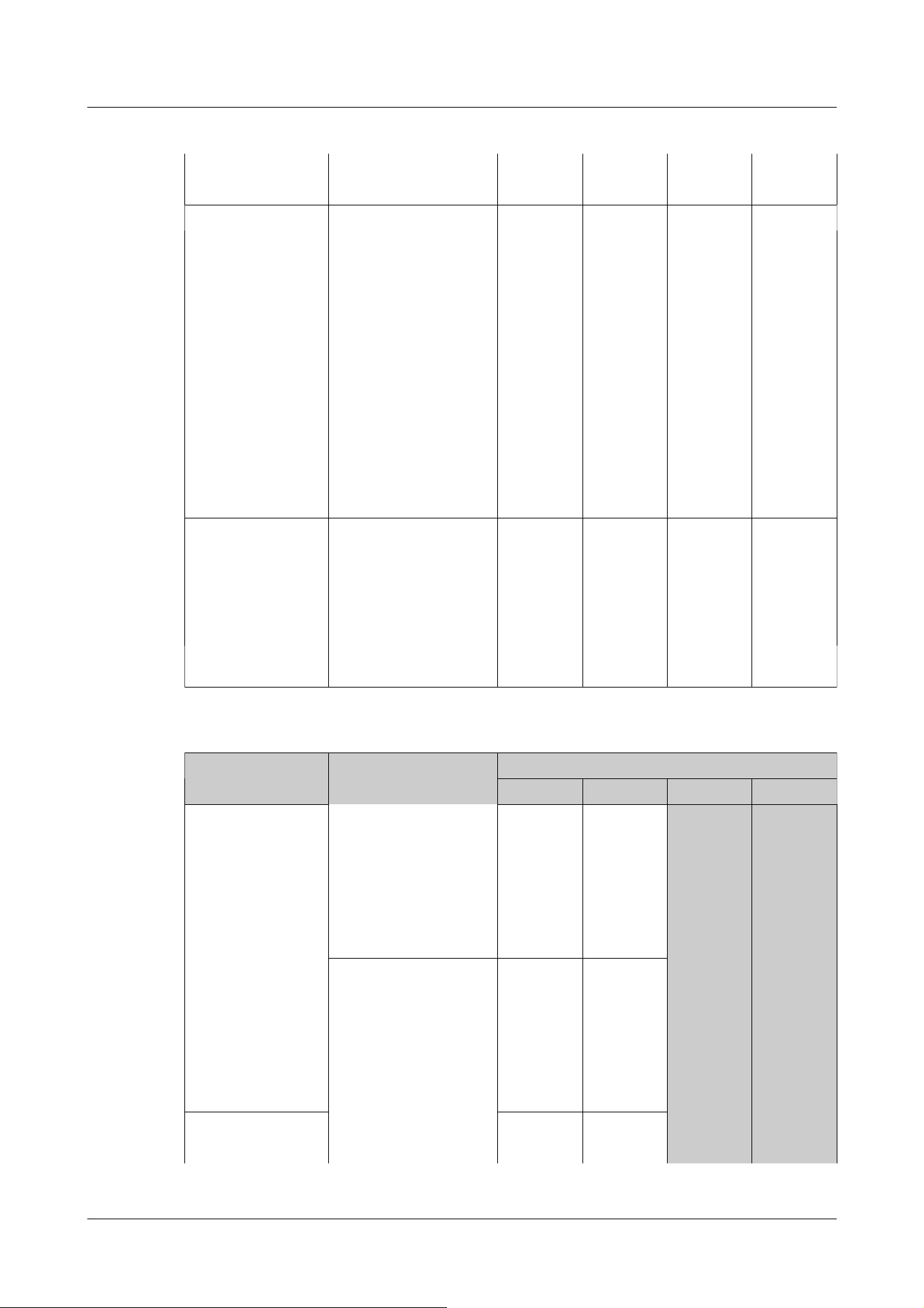
VGA VGA VGA
QVGA QVGA QVGA
Rapid PTZ
Camera(X/S
Series, Image
capture size: 8M
(4K)), Indoor PTZ
cameras (Image
capture size: 8M
(4K)), Aero PTZ
cameras (Image
capture size: 8M
(4K)))
16:9 mode(30fps mode)
16:9 mode(25fps mode)
3840x2160 3840x2160
2560x1440 2560x1440
1920x1080
1280x720 1280x720 1280x720
640x360 640x360 640x360
320x180 320x180 320x180
Rapid PTZ
Camera(X/S Series,
Image capture size:
6MP), Indoor PTZ
cameras (Image
capture size: 6MP)
16:9 mode(30fps mode)
16:9 mode(25fps mode)
3328x1872 3328x1872
2560x1440 2560x1440
1920x1080
1280x720 1280x720 1280x720
640x360 640x360 640x360
320x180 320x180 320x180
Aircraft type Imaging mode
H.265/H.264
Stream 1 Stream 2 Stream 3 Stream 4
Multi-directional
cameras
(8-megapixel
models)
8 megapixels [16:9](15
fps mode)
8 megapixels
[16:9](12.5 fps mode)
3840x2160 --
(Without
function)
--
(Without
function)
2560x1440
1920x1080
1280x720
640x360
320x180
8 megapixels [16:9](15
fps Dual mode)
8 megapixels
[16:9](12.5 fps Dual
mode)
3840x2160
2560x1440
1920x1080
1280x720
640x360
320x180
Multi-directional
camera (5-
5 megapixels
[16:9](15fps mode)
3072x1728
2560x1440
Multi-directional camera
10 [Image/Audio] for setting images and sound files
10.3 [Image] for setting up streams
302

megapixel model) 5 megapixels
[16:9](12.5fps mode)
1920x1080
1280x720
640x360
320x180
5 megapixels
[16:9](15fps Quad mode)
5 megapixels
[16:9](12.5fps Quad
mode)
3072x1728
2560x1440
1920x1080
1280x720
640x360
5 megapixels [4:3](15fps
mode)
5 megapixels
[4:3](12.5fps mode)
3072x2304
2560x1920
1280x960
VGA
QVGA
5 megapixels [4:3](15fps
Quad mode)
5 megapixels
[4:3](12.5fps Quad
mode)
3072x2304
2560x1920
1920x1080
1280x960
640x480
Multi-directional
camera (4-
megapixel model)
4 mega pixel
[16:9](30fps mode)
4 mega pixel
[16:9](25fps mode)
2688x1520
2560x1440
1920x1080
1280x720 1280x720
640x360
320x180
4 mega pixel
[16:9](30fps Dual mode)
4 mega pixel
[16:9](25fps Dual mode)
2688x1520
2560x1440
1920x1080
1280x720 1280x720
640x360
[Note:]
・If [Image rotation] is set to [90°] or [270°] on the [Basic] tabs of the basic
pages, the resolution [320x180] cannot be set.
・[New X Fixed][AI Outdoor IR BulletX] Image capture size [320x180] can be set
even if [Image rotation] is set to [90°] or [270°] on [Basic] tab. of the basic
page.
・[MULTI] This setting is common to all cameras.
10 [Image/Audio] for setting images and sound files
10.3 [Image] for setting up streams
303

・[MULTI2] When Stream (1) is 2688x1520 and Stream (2) is 1280x720, the frame
rate is limited to a maximum of 15fps (maximum 12.5fps in 25fps mode).
[Note:]
・Setting [Transmission priority] to [Frame rate] may result in fewer users being
able to connect.
・[MULTI] This setting is common to all cameras.
[Note:]
・[Frame rate*] is restricted to [Max bit rate (per client) *]. When a value with [*]
is set, the frame rate may be lower than the set value. If [Transmission priority] is
set to [VBR], the image may be suspended periodically depending on the [Max bit
rate (per client) *] and [Image quality] settings. Confirm the image delivered after
setting.
・The [*] option is omitted.
・The frame rate up to the value of the selected imaging mode can be selected.
[Transmission priority]
Set the stream delivery mode from the following.
・ [Constant bit rate]:The H.265 (or H.264) images are delivered at the bit rate set by [Max bit
rate (per client) *].
・ [VBR]:The H.265 (or H.264) images are delivered at the frame rate set by [Frame rate*] while
maintaining the image quality level set by [Image quality]. At this time, the bit rate is varied within
the maximum bit rate set by [Max bit rate (per client) *]. The recording capacity varies depending
on the [Image quality] settings and subject conditions.
・ [Frame rate]Deliver H.265 (or H.264) images at the frame rate set by [Frame rate*].
・ [Best effort]The H.265 (or H.264) images are delivered with varying bit rates within the
maximum bit rate set by [Max bit rate (per client) *], depending on the bandwidth of the networks.
[Frame rate*]
Set the frame rate from the following.
-For [16:9 mode(30fps mode)]/[16:9 mode(60fps mode)]/[4:3 mode(30fps mode)]/[4:3
mode(15fps mode)]:
1fps/ 3fps/ 5fps/ 7.5fps/ 10fps/ 12fps/ 15fps/ 20fps/ 30fps/ 60fps
-For [16:9 mode(25fps mode)]/[16:9 mode(50fps mode)]/[4:3 mode(25fps mode)]/[4:3
mode(12.5fps mode)]:
1fps/ 3.1fps/ 4.2fps/ 6.25fps/ 8.3fps/ 12.5fps/ 20fps/ 25fps/ 50fps
10 [Image/Audio] for setting images and sound files
10.3 [Image] for setting up streams
304

・Depending on the number of concurrent users or the combination of functions
used, the frame rate may be lower than the set value. Confirm the image delivered
after setting.
・If the frame rate is set low, the image may not be displayed properly depending on
the web browser you use.
・60 fps can be selected only when [Image capture mode] is in [16:9 mode (60 fps
mode)]. In this case, stream (1) will be [fixed at 60 fps]. [Stream(2)] ~ [Stream(4)]
can be up to 10 fps.
・50 fps can be selected only when [Image capture mode] is in [16:9 mode (50 fps
mode)]. In this case, stream (1) is set to [Fix 50fps]. [Stream(2)] ~ [Stream(4)]
can be up to 8.3 fps.
・[MULTI] This setting is common to all cameras.
・[New X Fixed-8M][New X Fixed-6M][AI Outdoor IR BulletX-8M]60fps can be
selected only when [Image capture mode] is set to [16:9 mode(60fps mode)].In
such cases, streaming (1) is set to [60fps fixed]. Also, [Stream(2)] ~ [Stream(4)]
will be unavailable.
・[New X Fixed-8M][New X Fixed-6M][AI Outdoor IR BulletX-8M]50fps can be
selected only when [Image capture mode] is set to [16:9 mode(50fps mode)].In
such cases, streaming (1) is set to [50fps fixed]. Also, [Stream(2)] ~ [Stream(4)]
will be unavailable.
・[New X Fixed-5M][AI Outdoor IR BulletX-5M]60fps can be selected only when
[Image capture mode] is set to [16:9 mode(60fps mode)] [4:3 mode (60fps mode)].
In such cases, streaming (1) is set to [60fps fixed]. Also, [Stream(2)] ~ [Stream(4)]
will be unavailable.
・[New X Fixed-5M][AI Outdoor IR BulletX-5M]50fps can be selected only when
[Image capture mode] is set to [16:9 mode(50fps mode)] [4:3 mode (50fps mode)].
In such cases, streaming (1) is set to [50fps fixed]. Also, [Stream(2)] ~ [Stream(4)]
will be unavailable.
・[New X Fixed-2M][New X Fixed-5M][AI Outdoor IR BulletX-2M][AI Outdoor IR
BulletX-5M]60fps can be selected only when [Image capture mode] is set to [16:9
mode(60fps mode)] [4:3 mode (60fps mode)]. In such cases, streaming (1) is set to
[60fps fixed].
・[New X Fixed-2M][New X Fixed-5M][AI Outdoor IR BulletX-2M][AI Outdoor IR
BulletX-5M]50fps can be selected only when [Image capture mode] is set to [16:9
mode(50fps mode)] [4:3 mode (50fps mode)]. In such cases, streaming (1) is set to
[50fps fixed].
10 [Image/Audio] for setting images and sound files
10.3 [Image] for setting up streams
305

[Note:]
・Refer to the catalog specifications for resolutions that can be selected for each
model.
・The bit rate of streams is restricted to [Bandwidth control(bit rate)] on the
[Network] tabs of network pages. Therefore, when the value with [*] is set, the
image may not be delivered.
→16.1 Networking [Network]
・It is recommended that the bit rate of the stream be set to 8192 kbps or less. If a
value greater than 8192 kbps is set, the continuity of recorded images may be
abnormal.
,
[Max bit rate (per client) *]
Select H.265 (or H.264) bit rate for one client from the following.
64kbps/128kbps */ 256kbps */ 384kbps */ 512kbps */ 768kbps */ 1024kbps */ 1536kbps */
2048kbps */ 3072kbps */ 4096kbps */ 6144kbps */ 8192kbps */ 10240kbps */ 122888kbps */
14336kbps */ 16384kbps */ 20480kbps */ 24576kbps */---free input
If [-----] is selected, the bitrate can be entered freely to the extent that it can be set.
If [Transmission priority] is [Constant bit rate], [Frame rate], or [Best effort]
320x180, 640x360, QVGA, 400x300, VGA, 800x600: 64 kbps to 4096 kbps *
1280x720
*1
For 1280 x 960: 128 kbps *~ 8192 kbps *
1920x1080
*1
For: 256 kbps *~ 12288 kbps *
For 2048 x 1536
*1
: 512 kbps *~ 16384 kbps *
For 2560 x 1440, 2560 x 1920: 768 kbps *~ 24576 kbps *
For 3072 x 1728: 1024 kbps *~ 24576 kbps *
For 3072 x 2304: 1536 kbps *~ 24576 kbps *
3840 x 2160 : 2048 kbps *~ 24576 kbps *
When [Transmission priority] is [VBR]
320x180, 640x360, QVGA, 400x300, VGA, 800x600: 64 kbps to 12288 kbps *
1280x720
*1
For 1280 x 960: 128 kbps *~ 12288 kbps *
1920x1080
*1
In the case: 256 kbps *~ 24576 kbps *
For 2048 x 1536: 512 kbps *~ 24576 kbps *
For 2560 x 1440, 2560 x 1920: 768 kbps *~ 24576 kbps *
For 2688 x 1520: 768 kbps to 24576 kbps
For 3072 x 1728: 1024 kbps *~ 24576 kbps *
For 3072 x 2304: 1536 kbps *~ 24576 kbps *
For 3840 x 2160: 2048 kbps *~ 24576 kbps *
10 [Image/Audio] for setting images and sound files
10.3 [Image] for setting up streams
306

・When the refresh interval is short, the bit rate may be exceeded depending on
the subject.
・Depending on the number of concurrent users or the combination of functions
used, the bit rate may be lower than the set value. Confirm the image delivered
after setting.
・If you use [60fps mode] or [50fps mode] at the resolution of *1, you can set up to
24576 kbps.
・[MULTI] This setting is common to all cameras.
[Note:]
・This function can be used with [Stream(1)] only. If [On(High)] or [On(Low)] is
selected, the VIQS settings are disabled from the [Image quality] tabs.
・[MULTI4] [MULTI3] When [Smart VIQS] is set to [On(High)] or [On(Low)], the
[Image quality]
Select the image quality for the H.265 (or H.264) image from the following.
For [Constant bit rate], [Frame rate], [Best effort]:Movement priority/Standard/Image quality
priority
For [VBR]: [0 maximum image quality]/[1 Fine]/2/3/4/[5 Normal]/6/7/8/[9 Low]
Smart Coding-[Auto VIQS]
Images are distributed so that the quality of images in moving places is high and the amount of
data in other places is low.
[Off]:Auto VIQS is not used.
[On]:It keeps the image quality in the moving place high and reduces the amount of data in other
places.
Smart Coding-[Smart VIQS]
Images are distributed so that the amount of data decreases while maintaining high image quality
in areas with objects (head, people, cars and motorcycles) and low/medium/medium image quality
in other areas.
[Off]:Do not use smart VIQS.
[On(High)]:Images are distributed so that the image quality in the area where the object (head,
people, automobiles, and motorcycles) is located is maintained at a high level, while the image
quality in other areas is maintained at a low level and the amount of data is reduced.
[On(Low)]:Images are distributed so that image quality is high in areas with objects (head, people,
cars, and motorcycles) and medium image quality is maintained in other areas while data volume is
low.
10 [Image/Audio] for setting images and sound files
10.3 [Image] for setting up streams
307

frame rate is limited to 7.5 fps maximum in 15 fps mode, 6.25 fps maximum in 12.5
fps mode, 15 fps maximum in 30 fps mode, and 12.5 fps maximum in 25 fps mode.
・[New X Fixed-8M][New X Fixed-6M][New X Fixed-5M][AI Outdoor IR
BulletX-8M][AI Outdoor IR BulletX-5M]If [Image capture mode] is set to [60fps
Mode] or [50fps Mode], [Smart VIQS] cannot be used.
[Note:]
・This function can be used with [Stream(1)] only. If [On] is selected, the VIQS
settings are disabled from the [Image quality] tabs.
・When [On] is selected, movement may not be smooth or noise may be generated
in areas without objects (heads, people, cars, and motorcycles).
・[MULTI4] [MULTI3] When [Smart P-picture control] is set to [On], the frame
rate is limited to 7.5 fps maximum in 15 fps mode, 6.25 fps maximum in 12.5 fps
mode, 15 fps maximum in 30 fps mode, and 12.5 fps maximum in 25 fps mode.
・[New X Fixed-8M][New X Fixed-6M][New X Fixed-5M][AI Outdoor IR
BulletX-8M][AI Outdoor IR BulletX-5M] If [Image capture mode] is set to [60fps
Mode] or [50fps Mode], [Smart P-picture control] cannot be used.
[Important]
・When [Low], [Mid], [Mid], or [Frame rate control (Variable GOP4s-16s + Frame
rate control)] is selected, recording cannot be performed on the SD Memory
Card. If Advanced (fixed GOP 60s + 1s keyframe) is selected, the data can be
recorded on SD cards only with [Manual] [Schedule].
Smart Coding-[Smart P-picture control]
To reduce the amount of data, control the generation of data (macroblock) as little as possible
except where there is an object (head, person, car, or motorcycle).
[Off]:Smart P picture control is not used.
[On]:In order to reduce the amount of data, P-picture data is controlled to be generated as little
as possible in areas other than those with an object (head, person, car, or motorcycle).
Smart Coding-[GOP control]
The GOP control reduces the amount of data.
If [H.265] is selected in [Stream encoding format]: [Off]/Low/Mid/Advanced/Frame rate control
If [H.264] is selected in [Stream encoding format]: [Off]/[Low]/[Mid(variable GOP 4s-16s)]
10 [Image/Audio] for setting images and sound files
10.3 [Image] for setting up streams
308

[Note:]
・Using GOP control increases the refresh interval for the H.265 (or H.264) image.
Therefore, do not use in network environments where there are many errors.
・[Low]/[Mid]/[Frame rate control (variable GOP4s-16s + frame rate control)] can
be set only when [VBR] is selected in [Transmission priority]. [Advanced (Fixed
GOP 60s + 1s keyframe)] can be set regardless of the [Transmission priority].
・[Low (variable GOP 1s-8s)], [Mid (variable GOP 4s-16s)], and [Frame rate
control (variable GOP 4s-16s + frame rate control)] can reduce the amount of
data when there is no detectable object (face, person, car, or motorcycle) in the
image. [Advanced (fixed GOP 60s + 1s keyframe)] reduces the amount of data
regardless of the presence or absence of the sensing object.
・When [Frame rate control] is set, the frame rate can be changed from 1fps to
[Frame rate*] depending on the presence or absence of the sensing object.
・When [Frame rate control] is set, the display may temporarily slow or fast when
the frame rate is switched.
・[MULTI] When [GOP control] is set to [Low(Variable GOP 1s-8s)], [Mid
(Variable GOP 4s-16s)], [Advanced(Fixed GOP 60s w/1s key-frame)] or [Frame
rate control(Variable GOP 4s‑16s w/frame rate control)] is selected, the bit rate
will be limited.
・[MULTI4] [MULTI3] [GOP control] is set to [Low(Variable GOP 1s-8s)],
[Mid(Variable GOP 4s-16s)] or [Frame rate control(Variable GOP 4s‑16s
w/frame rate control)], the frame rate is limited to 7.5 fps maximum in 15 fps
mode, 6.25 fps maximum in 12.5 fps mode, 15 fps maximum in 30 fps mode, and
12.5 fps maximum in 25 fps mode.
・[New X Fixed-8M][New X Fixed-6M][New X Fixed-5M][AI Outdoor IR
BulletX-8M][AI Outdoor IR BulletX-5M] If [Image capture mode] is set to [60fps
Mode] or [50fps Mode], [GOP control] cannot be used.
[Refresh interval]
Select the refresh interval (I-Picture interval: 0.2 to 5 seconds) for the H.265 (or H.264) image
from the following.
If there are many errors in the network environment, the image will be less distorted if the refresh
interval is shortened.
However, the updating speed of the image may decrease or the bit rate may be exceeded.
[0.2s]/ [0.25s]/ [0.33s]/ [0.5s]/ [1s]/ [2s]/ [3s]/ [4s]/ [5s]
10 [Image/Audio] for setting images and sound files
10.3 [Image] for setting up streams
309

[Note:]
・If [GOP control] is set to Low (variable GOP 1s-8s), the refresh interval is set to
8s.
・If [GOP control] is set to Mid (variable GOP 4s-16s), the refresh interval is set
to 16s.
・If [GOP control] is set to Advanced (fixed GOP 60s + 1s keyframe), the refresh
interval is set to 60s.
・If [GOP control] is set to [Frame Rate Control (variable GOP 4s-16s + frame
rate control)], the frame rate can be varied between values set from 1fps to
[Frame rate*] according to the magnitude of the image change. The lower the
frame rate, the longer the refresh interval. The maximum refresh interval is 16s.
・[MULTI] This setting is common to all cameras.
[Note:]
・For the maximum number of simultaneous unicast accesses, see the following.
→2.3.1 View camera images
・If [Unicast port (MANUAL)] is selected, you must configure a unicast port number.
・When multicast is set, the browser will not be able to view the H.265 image (or
[Transmission type]
Select the distribution method of H.265 (or H.264) image from the following.
[Unicast port (AUTO)]:
When sending images and sounds from your computer, [Unicast port1(Image)] and [Unicast
port2(Audio)] are automatically set. If you do not need to fix the number of the ports on which the
streams are delivered, such as when used in networks, it is recommended that you set it to
[Unicast port (AUTO)].
[Unicast port (MANUAL)]:
When sending images and audio from the computer, the [Unicast port1(Image)] and [Unicast
port2(Audio)] must be set manually. When accessing a camera using a browser, the port number is
automatically selected even in this setting. When distributing a stream over the Internet, fix the
port number to be used as the Broadband Router (hereinafter referred to as the Router). For
details, refer to the router's instruction manual.
→16.1 Networking [Network]
[Multicast]:
You can access this machine at the same time without restricting the number of people. To send
streams in multicast, enter [Multicast address], [Multicast port], and [Multicast TTL/HOPLimit].
10 [Image/Audio] for setting images and sound files
10.3 [Image] for setting up streams
310

H.264 image).
・If [Multicast] is selected, you must configure multicast IP addresses.
・[MULTI] This setting is common to all cameras.
[Note:]
・Check and enter the available multicast IP address.
[Note:]
・When sending audio from your computer, the multicast port number plus [1000]
is used.
[Important]
・When delivering a stream over the Internet, the distribution image may not be
displayed depending on the settings of the proxy server, firewall, etc. In this case,
contact your network administrator.
,
[Unicast port1(Image)]
Enter the unicast port number (used to send images from your computer).
Configurable port number:1024 to 50000 (even number only)
[Unicast port2(Audio)]
Enter the unicast port number (to be used when sending audio from your computer).
Configurable port number:1024 to 50000 (even number only)
[Multicast address]
Enter the multicast IP address.
Send images and sound to the specified IP address.
IPv4 configurable range:224.0.0.0~239.255.255.255
IPv6 configurable range:Multicast addresses starting with FF
[Multicast port]
Enter the multicast port number (used when sending images from your computer).
Configurable port number:1024 to 50000 (even number only)
[Multicast TTL/HOPLimit]
Enter the TTL/HOPLimit value for the multicast.
Settable value:1~254
10 [Image/Audio] for setting images and sound files
10.3 [Image] for setting up streams
311

・If you want to display multicast images using a PC with multiple LAN cards,
disable LAN cards that are not used for reception.
10.4 [Image quality] to set the image quality
Click on the [Image quality] tabs of the video and audio pages. Refer to the following how to
display and operate the Advanced menu.
→5.1 How to display
→5.2 How to operate
To Advanced Settings for each item>>Clicking this button displays the advanced settings window
in a separate window and allows you to set the settings while viewing the images displayed on the
[Image quality] tab.
You can set the image quality adjustment, zoom/focus, privacy zone, VIQS, and lens distortion
compensation.
Multi-directional cameras (Multi part)
10 [Image/Audio] for setting images and sound files
10.4 [Image quality] to set the image quality
312
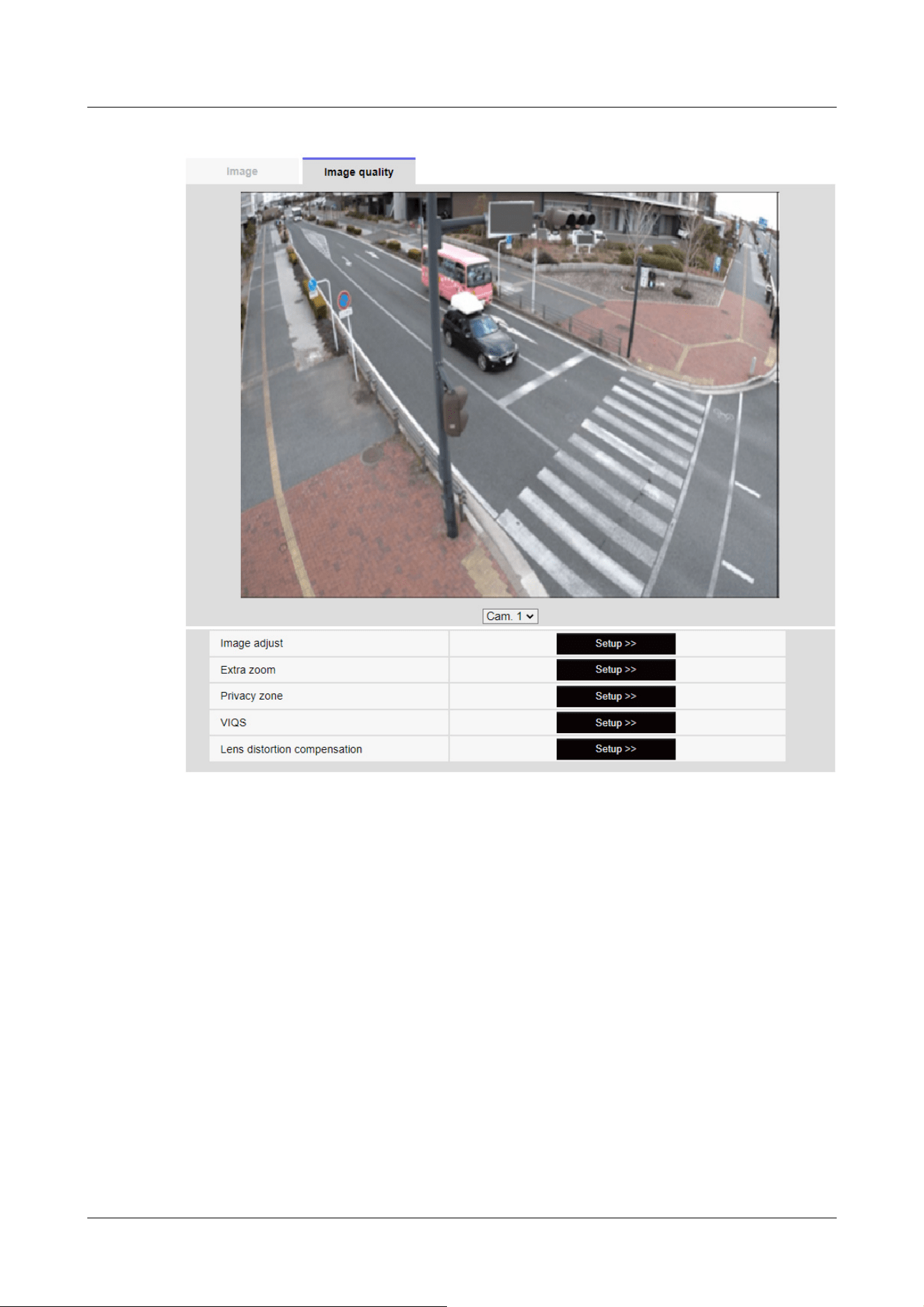
Corner cameras
10 [Image/Audio] for setting images and sound files
10.4 [Image quality] to set the image quality
313
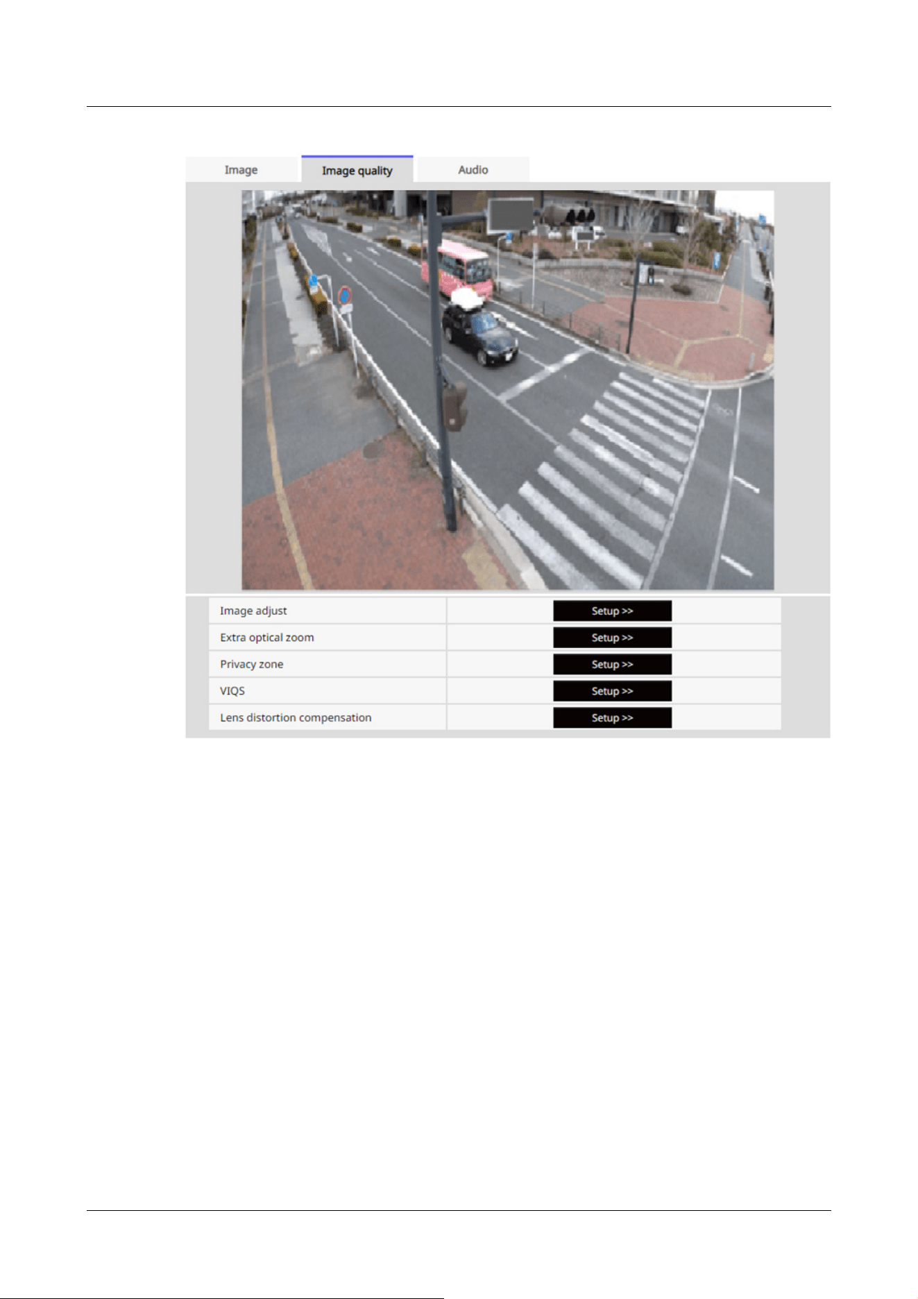
Rapid PTZ Cameras, AI Outdoor IR Bullet Camera
10 [Image/Audio] for setting images and sound files
10.4 [Image quality] to set the image quality
314
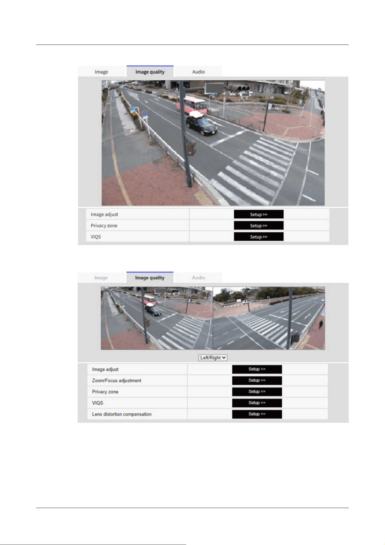
Multi-directional cameras (2 eyes), New X Fixed cameras, U-series camera with edge AI
Selecting the camera from the pull-down menu at the bottom of the screen displays the live
picture of the selected camera. You can view the image quality adjusted on this screen.
10 [Image/Audio] for setting images and sound files
10.4 [Image quality] to set the image quality
315

[Note:]
・[MULTI] Only Multi-directional cameras can be selected.
[Image adjust]
To Advanced Settings>>When the [button] is clicked, the image quality setting window is
displayed in a separate window.
→10.4.1 To adjust the image quality (image quality adjustment screen)
[Image adjust]
To Advanced Settings>>When the [button] is clicked, the image quality setting window is
displayed in a separate window.
→10.4.1 To adjust the image quality (image quality adjustment screen)
[Digital zoom(Extra zoom)]
To Advanced Settings>>When the button is clicked, Digital zoom(the EX zoom) setting window is
displayed in a separate window.
→10.4.3 Adjust the angle of view with the Digital zoom(EX zoom)
[Digital zoom(Extra optical zoom)]
To Advanced Settings>>When the button is clicked, Digital zoom(the Ex optical zoom) setting
window is displayed in a separate window.
→10.4.4 Adjust the angle of view with the Digital zoom(Ex optical zoom)
[Zoom/focus adjustment]
To Advanced Settings>>When the button is clicked, the zoom and focus settings window is
displayed in a separate window.
→10.4.5 Adjust the zoom/focus
[Privacy zone]
To Advanced Settings>>Click the [Privacy Zone] button to open the Privacy Zone Settings
window.
→10.4.6 Setting the privacy zone (Privacy zone setting screen)
[VIQS]
To Advanced Settings>>Click the [VIQS] button to display the VIQS settings window.
→10.4.7 Set up VIQS
[Lens distortion compensation]
To Advanced Settings>>Click this button to display the setting window for lens distortion
compensation in a separate window.
→10.4.9 Set the lens distortion compensation
10 [Image/Audio] for setting images and sound files
10.4 [Image quality] to set the image quality
316
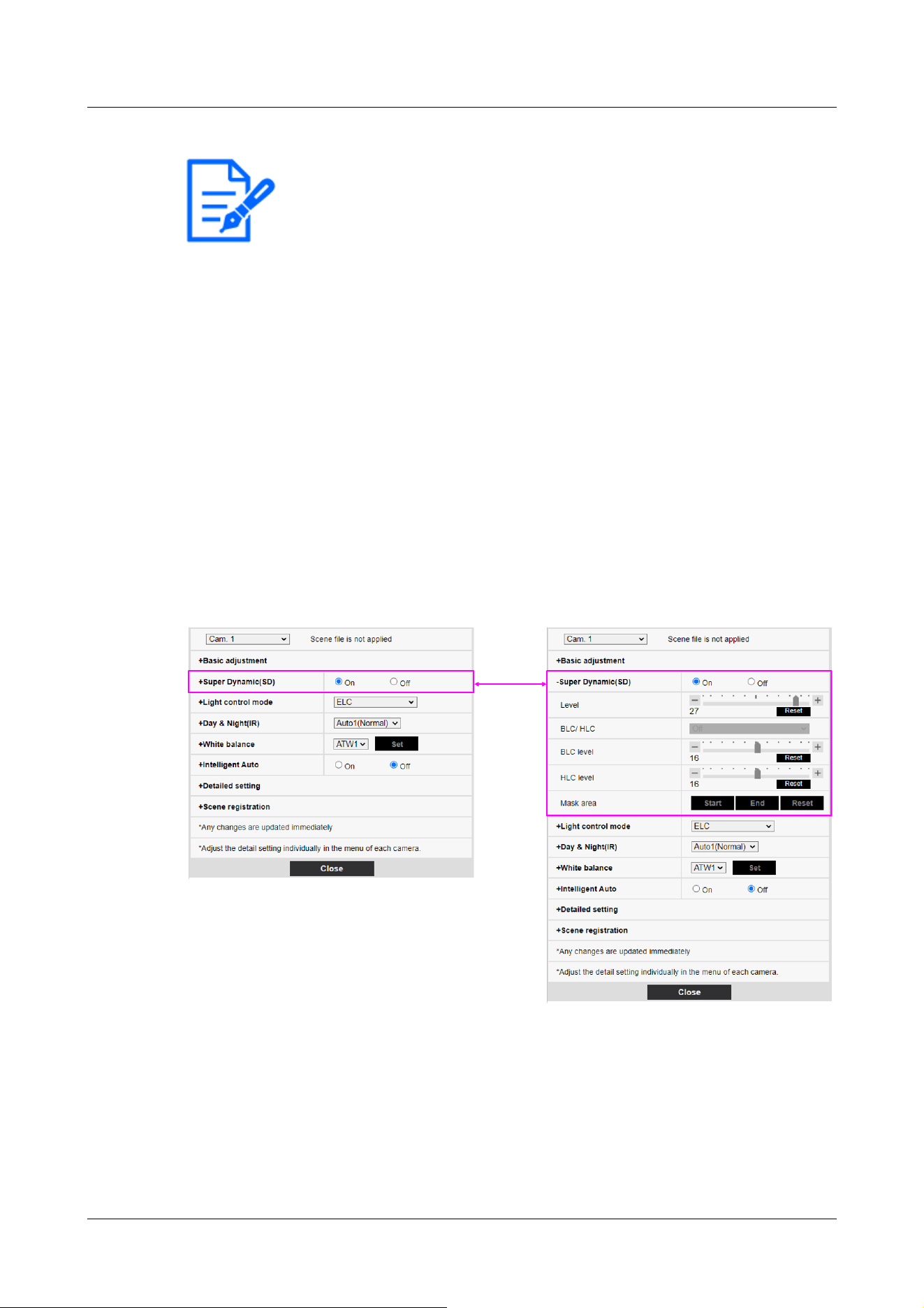
[Note:]
・Items displayed differ depending on the model. Refer to the catalog specifications
for the functions installed in each model.
・[PTZ] See the following for the operation of the zoom function of the PTZ camera.
→11.1 [Cam. Function] for setting the operation of cameras
10.4.1 To adjust the image quality (image quality adjustment screen)
In the Video/Audio [Image quality] tabs to [Image adjust] Advanced Settings>>Click the [Button].
→10.4 [Image quality] to set the image quality
Image quality is set in the setting screen displayed in a separate window. When you change the
values, the images displayed on the [Image quality] tabs also reflect the changes.
Click + on the left side of each item in the setting screen to expand each item and display detailed
settings.
Click-> on the left of each expanded item to return to the previous window.
<Example: Basic image quality adjustment>
[Camera selection]
Select the camera that reflects the image quality settings.
[Common(Cam. 1-2)]:The settings are made simultaneously for each camera. The images
displayed on the [Image quality] tabs are divided into cameras.
[Camera 1]:Sets camera 1 image quality. The image displayed on the [Image quality] tab is the
10 [Image/Audio] for setting images and sound files
10.4 [Image quality] to set the image quality
317

[Note:]
・[MULTI] [Camera selection] can be selected only for Multi-directional cameras.
・[MULTI] For [Common(Cam. 1-2)], for [Super Dynamic], [Light control mode],
[White balance], and Intelligence Auto, only items can be set up prior to the
advanced settings. To perform other advanced settings, select each camera.
camera-1 image.
[Camera 2]:Sets camera 2 image quality. The image displayed on the [Image quality] tab is
camera-2 image.
[Camera 3]:Set the image quality of camera 3. The image displayed on the [Image quality] tab is
the camera-3 image.
[Camera 4]:Set the image quality of camera 4. The image displayed on the [Image quality] tab is
the camera 4 image.
Basic image quality adjustment
[Brightness]
Adjust the brightness.
Move the slider bar in the [+] direction to brighten the image.
Move the slider bar in the [-] direction to darken the image.
Press [Reset] to return to the default brightness.
[Maximum gain]
Adjust the maximum gain. When the subject's illumination becomes dark, the gain automatically
increases and the screen brightens.
Increasing the gain may increase the noise.
Move the slider bar in the [+] direction to increase the maximum gain.
Move the slider bar in the [-] direction to reduce the maximum gain.
Press [Reset] to return to the default settings.
[Chroma gain level]
Adjust the chroma level (color intensity).
When the slider bar is moved in the [+] direction, it becomes bright and bright.
When the slider bar is moved in the [-] direction, the color becomes calm.
Press [Reset] to return to the default settings.
[Sharpness level]
Adjust the sharpness level (contour correction).
Moving the slider bar in the direction of [+] results in a sharp contour, while moving the slider bar
in the direction of [-] results in a soft contour.
Press [Reset] to return to the default settings.
10 [Image/Audio] for setting images and sound files
10.4 [Image quality] to set the image quality
318

[Note:]
・This cannot be set when [Image capture mode] is [16:9 mode(60fps mode)] or
[16:9 mode(50fps mode)].
・Set [Super Dynamic] to [Off] when the following phenomena are observed
depending on the lighting condition.
-when flickering or color changes occur
-when noise is generated in the bright area of the screen
・If [Light control mode] is set to [Fix shutter], [Super Dynamic] cannot be set to
[On].
・When [Stabilizer] is set to [On], the superdynamic setting is [Off].
[Digital noise reduction]
The digital noise reduction function automatically reduces noise at low illumination levels.
Move the slider bar in the direction of [+] to increase the effect of noise reduction. For more
afterimages
I have one.
Moving the slider bar in the direction of [-] reduces the noise reduction effect. There are fewer
aftereffects.
Press [Reset] to return to the default settings.
Superdynamic
[Super Dynamic]
You can set [On] or [Off] to activate the super dynamic function.
See [What is Super Dynamic] for details on super dynamic.
[On]:The Super Dynamic function is activated.
[Off]:Stops the superdynamic function.
[Level]
Adjust the superdynamic level.
When the slider bar is moved in the [+] direction, you can shoot a subject with a large difference in
light and darkness without flipping white or shading black.
Move the slider bar in the [-] direction to take a full picture of the middle brightness.
Press [Reset] to return to the default settings.
What is Superdynamic?
If there is a large difference between the bright and dark areas, the camera will set the lens
aperture to match the bright areas, making the dark areas invisible. Conversely, when the lens
aperture is adjusted to the dark area, the bright area is not visible.
Super Dynamic is a function of combining images with large brightness and darkness, and images
10 [Image/Audio] for setting images and sound files
10.4 [Image quality] to set the image quality
319
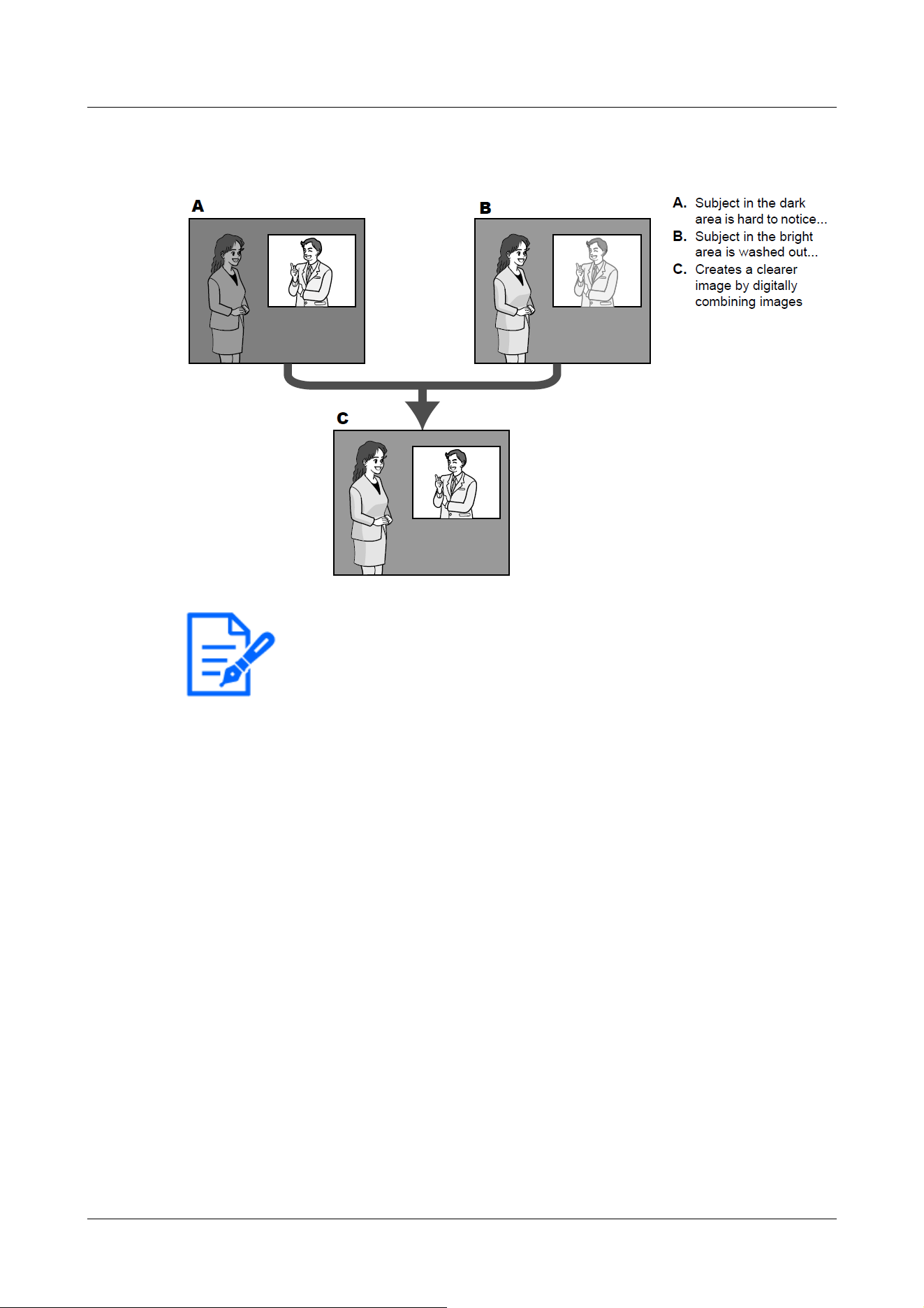
[Note:]
・[New X Fixed-8MP][New X Fixed-6MP][New X Fixed-5MP][AI Outdoor IR
BulletX-8M][AI Outdoor IR BulletX-5M][AI Outdoor IR BulletS-8M][AI Outdoor
IR BulletS-5M]If [Level] is set to 30 or higher, [Frame Rate] is limited to the
highest 15fps.
with large darkness, and reproducing brightness and darkness faithfully.
[BLC/ HLC]
Select from the following. This setting is not available if [Super Dynamic] is set to [On] or
[Intelligent Auto] is set to [On].
[Back light compensation(BLC)]:Enables the backlight correction function.
[High light compensation(HLC)]:Enables the high light correction function. Illumination
compensation suppresses bright lighting of subjects such as car headlights during nighttime.
[Off]:Stops the backlight compensation function and the intense light correction function.
[BLC level]
Adjust the backlight correction level.
Moving the slider bar in the [+] direction improves the backlight correction effect. Moving the
slider bar in the [-] direction reduces the effect of backlight correction.
Press [Reset] to return to the default settings.
[HLC level]
Adjust the intensity correction level.
10 [Image/Audio] for setting images and sound files
10.4 [Image quality] to set the image quality
320

[Note:]
・[MULTI] When [Common(Cam. 1-2)] is selected in [Camera selection], the mask
area cannot be set. Set for each camera.
Moving the slider bar in the [+] direction improves the effect of intense light correction. Moving
the slider bar in the [-] direction reduces the effect of intense light correction.
Press [Reset] to return to the default settings.
[Mask area]
When the mask area is set, the set area can be masked and the light intensity can be adjusted. If
[Super Dynamic] is set to [On], it cannot be set.
For details on how to set the mask area, refer to the following.
→10.4.2 Set the mask area
Light intensity control mode
[Light control mode]
Select the mode to control the light intensity from the following.
[Outdoor scene]:The brightness (illumination) controls the light intensity by combining the
electronic shutter and automatic aperture. This setting is used when shooting bright subjects such
as outdoors. Be careful not to flicker under fluorescent lights, etc.
[Flickless (50 Hz)]/[Flickless (60 Hz)]:Flicker is automatically corrected with a fluorescent lamp.
50 Hz/60 Hz will be used differently in different regions.
ELC:The electronic shutter is used to control the light intensity.
[Fix shutter]:
If [Image capture mode] is [Single source [4:3](30fps mode)]/[Dual sources [4:3](15fps mode)]:
[1/30 fixed], [3/120 fixed], [2/100 fixed], [2/120 fixed], [1/100 fixed], [1/120 fixed], [1/250
fixed], [1/500 fixed], [1/1000 fixed], [1/2000 fixed], [1/4000 fixed], or [1/10000 fixed]
If [Image capture mode] is [Single source [4:3](25fps mode)]/[Dual sources [4:3](12.5fps mode)]:
[1/25 fixed]/[3/100 fixed]/[2/100 fixed]/[1/100 fixed]/[1/250 fixed]/[1/500 fixed]/[1/1000
fixed]/[1/2000 fixed]/[1/4000 fixed]/[1/10000 fixed]
If [Image capture mode] is in [60fps mode]:
[1/60 fixed]/[1/100 fixed]/[1/120 fixed]/[1/250 fixed]/[1/500 fixed]/[1/1000 fixed]/[1/2000
fixed]/[1/4000 fixed]/[1/10000 fixed]
If [Image capture mode] is in [50fps mode]:
[1/50 fixed]/[1/100 fixed]/[1/250 fixed]/[1/500 fixed]/[1/1000 fixed]/[1/2000 fixed]/[1/4000
fixed]/[1/10000 fixed]
10 [Image/Audio] for setting images and sound files
10.4 [Image quality] to set the image quality
321

[Note:]
・Refer to the catalogue specifications for the [Light control mode] that can be
selected for each model.
・If you increase the shutter speed (~1/10,000), you will be less prone to blur
even when the subject moves faster.
・Increasing the shutter speed decreases the sensitivity.
・If [Super Dynamic] is set to [On], [Fix shutter] cannot be set.
・To configure [Fix shutter], set [Super Dynamic] to [Off].
・If [Image capture mode] is [Single source [4:3](25fps mode)], [50fps mode], or
[Dual sources [4:3](12.5fps mode)], [Flickerless 60Hz] cannot be set.
・When [25fps mode], [50fps mode], or [12.5fps mode] is selected for [Image
capture mode], [Indoor scene(60 Hz)] is not available.
・It may be able to reduce flickering by switching the [Image capture mode] as
follows:
– In the area where the power frequency is 60Hz: Switch the [Image capture
mode] to 30 fps mode or 15 fps mode.
– In the area where the power frequency is 50Hz: Switch the [Image capture
mode] to 25 fps mode or 12.5 fps mode.
[Maximum shutter]
The maximum exposure time adjusts the maximum storage time of the sensor. The following values
can be set.
Compact camera, Multi-directional camera, Corner cameras, U-series camera with edge
AI(WV-U22750-F3L、 WV-U25550-F3L、 WV-U22550-F3L、 WV-U25350-F3L、 WV-
U22350-F3L)
If [Image capture mode] is in 30 fps or 15 fps mode:
[Maximum 1/10000s]/[Maximum 1/4000s]/[Maximum 1/2000s]/[Maximum 1/1000s]/[Maximum
1/5000s]/[Maximum 1/250s]/[Maximum 1/120s]/[Maximum 2/120s]/[Maximum 2/120s]/
[Maximum 2/100s]/[Maximum 3/120s]/[Maximum 1/30s]/[Maximum 2/30s]/[Maximum
4/30s]/[Maximum 6/30s]/[Maximum 10/30s]/[Maximum 16/30s]
If [Image capture mode] is in 25 fps or 12.5 fps mode:
[maximum 1/10000 s]/[maximum 1/4000 s]/[maximum 1/2000 s]/[maximum 1/1000 s]/
[maximum 1/500 s]/[maximum 1/250 s]/[maximum 1/100 s]/[maximum 2/100 s]/[maximum
3/100 s]/[maximum 1/25 s]/[maximum 1/25 s]/[maximum 2/25 s]/[maximum 4/25 s]/[maximum
6/25 s]/[maximum 10/25 s]/[maximum 16/25 s]
10 [Image/Audio] for setting images and sound files
10.4 [Image quality] to set the image quality
322

[Important]
・When [Maximum shutter] is set to the following, the frame rate may decrease
when the subject is dark.
If the [Image capture mode] is in 30 fps or 15 fps mode:
Value longer than [1/30s maximum] ([2/30s maximum]/[4/30s maximum]/[6/30s
maximum]/[10/30s maximum]/[16/30s maximum])
If the [Image capture mode] is in 25 fps or 12.5 fps mode:
Value longer than [1/25s maximum] ([2/25s maximum]/[4/25s maximum]/[6/25s
maximum]/[10/25s maximum]/[16/25s maximum])
・[MULTI] If the frame rate is lowered for one or more cameras due to the above,
the frame rate is lowered for the other cameras whose exposure time has not
changed.
[Note:]
・Refer to the catalogue specifications for the [Maximum shutter] that can be
selected for the respective models.
・If [Super Dynamic] is set to [On], [Maximum 1/2000 s], [Maximum 1/4000 s], or
[Maximum 1/10000 s] cannot be set.
・If [Maximum gain] is set to [0], the [Maximum shutter] setting is restricted as
follows.
If [Image capture mode] is set to [Single source [4:3](30fps mode)]/[60fps
New X Fixed cameras, PTZ Cameras, AI Outdoor IR Bullet Camera, U-series camera with edge
AI(WV-U15750-V3L、 WV-U25751-V3L、 WV-U15550-V3L、 WV-U11550-V3、 WV-
U25551-V3L、 WV-U21550-V3L、 WV-U15350-V3L、 WV-U11350-V3、 WV-U25351-V3L、
WV-U21350-V3L)
If [Image capture mode] is in 30 fps or 15 fps mode:
[Maximum 1/4000s]/[Maximum 1/2000s]/[Maximum 1/1000s]/[Maximum 1/5000s]/[Maximum
1/250s]/[Maximum 1/120s]/[Maximum 2/120s]/[Maximum 2/120s]/[Maximum 2/100s]/
[Maximum 3/120s]/[Maximum 1/30s]/[Maximum 2/30s]/[Maximum 4/30s]/[Maximum
6/30s]/[Maximum 10/30s]/[Maximum 16/30s]
If [Image capture mode] is in 25 fps or 12.5 fps mode:
[maximum 1/4000 s]/[maximum 1/2000 s]/[maximum 1/1000 s]/[maximum 1/500 s]/[maximum
1/250 s]/[maximum 1/100 s]/[maximum 2/100 s]/[maximum 3/100 s]/[maximum 1/25
s]/[maximum 1/25 s]/[maximum 2/25 s]/[maximum 4/25 s]/[maximum 6/25 s]/[maximum 10/25
s]/[maximum 16/25 s]
10 [Image/Audio] for setting images and sound files
10.4 [Image quality] to set the image quality
323

mode]/[Dual sources [4:3](15fps mode)]:
[Maximum 2/30s] or more cannot be set.
If [Image capture mode] is set to [Single source [4:3](25fps mode)]/[50fps
mode]/[Dual sources [4:3](12.5fps mode)]:
[Maximum 2/25s] or more cannot be set.
・If [Light control mode] is set to [Flickless (60Hz)], the duration cannot be set to
less than [1/120s].
・If [Light control mode] is set to [Flickless (50Hz)], the duration cannot be set to
less than [1/100s].
[Light control speed]
Adjust the speed of light intensity adjustment.
Move the slider bar in the [+] direction to increase the speed of light adjustment.
Moving the slider bar in the [-] direction slows the light intensity adjustment speed.
Press [Reset] to return to the default settings.
Switching between black and white
[D&N]
Select the mode for switching between black-and-white and color images.
IR LED Light models
[Off]:It is always shot with color images.
[On(IR Light Off)]:The picture is always taken in black and white.
[On(IR Light On)]:The picture is always taken in black and white. This setting is used when
near-infrared lighting is used at night.
[Auto1(IR Light Off)]:The color image and black-and-white image are automatically switched
depending on the brightness (illumination) of the image.
[Auto2(IR Light On)]:The color image and black-and-white image are automatically switched
depending on the brightness (illumination) of the image. This setting is used when near-infrared
lighting is used at night.
[Auto3(SCC)]:Set this when you want to maintain a color image even when the light source is
dark. The Super ChromaCompensation (SCC) function maintains the color image to low brightness.
[Auto4(LPR)]:The color image and black-and-white image are automatically switched depending
on the brightness (illumination) of the image. To make the numbered plate easier to identify, when
it starts to darken, it switches to a black-and-white image early.
IR LED Light No-models, White LED Light models
[Off]:It is always shot with color images.
[On]:The picture is always taken in black and white.
10 [Image/Audio] for setting images and sound files
10.4 [Image quality] to set the image quality
324

[Note:]
・Refer to the catalog specifications for the functions installed in each model.
・The Auto3 (Super Chroma Compensation) setting uses color correction
techniques and may be displayed differently from the Full object depending on the
ambient illumination condition.
・The operation sound may be heard when switching between black and white.
However, this is not an error.
・Automatic color/black-and-white image switching may not work depending on the
environment. In this case, use the scheduling function to change the color
image/black-and-white image. How to set up is our technical information website
<Control No. C0314>
・[MULTI] If [D&N] is set to other than [Off], all cameras will be changed to the
same setting.
・[Rapid PTZ][AI Outdoor IR Bullet-30x model][AI Outdoor IR Bullet-LPF
model][Auto3(SCC)] cannot be selected.
・[Auto4(LPR)] Since the settings assume high-speed shutter operation, switching
between black-and-white and color images may be repeated when Maximum
shutter is set to a shutter setting of [Max. 1/120s] or less ([Max. 1/30s], etc.).
[Auto1(Normal)]:The color image and black-and-white image are automatically switched
depending on the brightness (illumination) of the image.
[Auto2(IR Light)]:The color image and black-and-white image are automatically switched
depending on the brightness (illumination) of the image. Set this when using white LED Light or
near-infrared illumination (external) at night.
[Auto3(SCC)]:Set this when you want to maintain a color image even when the light source is
dark. The Super Chroma Compensation (SCC) function maintains the color image to low illumination.
What is Super Chroma Compensation (SCC)?
This function enables the acquisition of color images that are faithful using a unique color
correction technology even in an environment with low illumination that cannot capture images
faithfully.
What is License Plate Recognition (LPR)?
This function identifies the license plate of the vehicle from the captured image and acquires
information on the license plate.
[Level]
Select the brightness (illumination) level to switch between color image and black-and-white
image from the following. The following switching illuminance is the illuminance when [Super
10 [Image/Audio] for setting images and sound files
10.4 [Image quality] to set the image quality
325

[Note:]
・The color image switching is about 5 to 8 times bright. It may vary depending on
the environment.
・If [Maximum gain] is set low, it may not be easy to switch over depending on the
environments.
[Note:]
・Only IR LED Light models can be selected for [IR LED light intensity].
・Refer to the catalog specifications for the functions installed in each model.
・When [Black & white input] is selected in [Terminal 1] of the [Alarm] tab, [Off]
can be selected.
・[MULTI] This setting is displayed only when [Camera selection] is set to
[Common(Cam. 1-2)]. The settings for each camera are not available.
Dynamic] is [Off].
3:The brightness (brightness) of the camera is about 8 lx or less, and the image is switched to
black and white.
2:The brightness (brightness) around the camera is about 4 lx or less, and the camera switches to
a black-and-white image.
1:The brightness (brightness) of the camera is about 2 lx or less and the image is switched to black
and white.
0:The brightness (brightness) around the camera is about 1 x or less, and the image is switched to
black and white.
[Dwell time]
Select the time before switching between color image and black-and-white image from the following.
[2s]/ [10s]/ [30s]/ [1min]
[IR LED light intensity]
Select IR LED light intensity from [High]/[Middle]/[Low]/[Off].
[IR LED light irradiation range control]
Select the setting for IR LED light irradiation range control from the following.
[Auto]: Automatically selects the appropriate IR Light of illumination according to the zoom
factor.
[Manual]: Enables you to set the irradiation range of IR Light in [IR LED light irradiation
range(Manual)].
10 [Image/Audio] for setting images and sound files
10.4 [Image quality] to set the image quality
326

[Note:]
・Refer to the catalog specifications for the functions installed in each model.
・[AI Outdoor IR Bullet]Only AI Outdoor IR Bullet Camera can be selected for [IR
LED light irradiation range control].
[Note:]
・You can set the [IR LED light irradiation range(Manual)] only when [Manual] is
selected for [IR LED light irradiation range control].
・Refer to the catalog specifications for the functions installed in each model.
・Press [Reset] to move the slide bar to position 4.
・[AI Outdoor IR Bullet]Only AI Outdoor IR Bullet Camera can be selected for [IR
LED light irradiation range(Manual)].
[Note:]
・Refer to the catalog specifications for the functions installed in each model.
・[MULTI] [IR Light Individual Setting] can be selected only for the IR LED Light
models of the Multi-directional camera.
[Note:]
・Only IR LED Light models can be selected for [IR LED light intensity].
・Refer to the catalog specifications for the selectable switching method for each
model.
・When [Intelligent Auto] is [On], [Intensity control] does not work.
・[MULTI] If [IR LED light intensity] is set to other than [Off], all cameras will be
changed to the same setting.
[IR LED light irradiation range(Manual)]
Set IR Light illumination area using the four slider bars.
You can adjust the value from 1 to 4. Moving it in the [+] direction will increase IR Light coverage.
[-] By moving it in the direction, you can narrow the range of IR Light.
IR Light individual settings
You can enable or disable each IR Light individually.
For more information, please refer to our technical information website<Control No. C0109>.
[Intensity control]
IR Light Sets ON/OFF whether the white and suppression function can be activated.
[White Light]
10 [Image/Audio] for setting images and sound files
10.4 [Image quality] to set the image quality
327

[Note:]
・By using this in conjunction with [Day & Night(IR)], you can shoot images with
angles of view where [White Light] cannot reach.
・Only White LED Light models can be selected for [White Light].
・Refer to the catalog specifications for the selectable switching method for each
model.
[Note:]
・Only White LED Light models can be selected for [White Light intensity].
・Refer to the catalog specifications for the selectable switching method for each
model.
[Note:]
・Colors may not be reproducible faithfully if the following conditions are met: In
such cases, set it to [AWC].
Most dark-colored subjects
Set whether to light the White Light with On/Off.
You can use the White Light to illuminate dark areas and brighten the surroundings.
On:Turns on the White Light.
Off:Turns off the White Light.
[White Light intensity]
Select from [High], [Middle], and [Low].
White balance
[White balance]
Select the white balance adjustment method from the following.
Adjust the white color with the R volume (adjusting red color) or the B volume (adjusting blue).
[ATW1]:Set the automatic color temperature tracking mode. The camera continuously checks the
color temperature of the light source and automatically adjusts the white balance. The operating
range is about 2700 K to 6000 K.
[ATW2]:Set the automatic color temperature tracking mode under sodium lamp. The camera
automatically adjusts the white balance under the sodium lamp. The operating range is from about
2000 K to 6000 K.
[AWC]:Set the automatic white balance control mode. Since the light source is fixed, it is suitable
for shooting where the light source does not change. The operating range is from approximately
2000 K to 10000 K.
10 [Image/Audio] for setting images and sound files
10.4 [Image quality] to set the image quality
328

The outgoing blue sky and the evening sun
Subject with too low illumination
・If [AWC] is selected, press [Set].
[Note:]
・[MULTI] When [Common(Cam. 1-2)] is selected in [Camera selection], the mask
area cannot be set. Set for each camera.
[Red gain]
Adjusts the red color of the image.
Move the slider bar in the [+] direction to darken the red color. When the slider bar is moved in
the [-] direction, the red color becomes light. Press [Reset] to return to the default settings.
[Blue gain]
Adjust the blue color of the image.
Move the slider bar in the [+] direction to darken the blue color. When the slider bar is moved in
the [-] direction, the blue color becomes light. Press [Reset] to return to the default settings.
[Mask area]
When the mask area is set, the set area can be masked and the white balance can be adjusted.
For details on how to set the mask area, refer to the following.
→10.4.2 Set the mask area
[Adjustment speed]
Adjust the white balance adjustment speed.
Move the slider bar in the [+] direction to increase the white balance adjustment speed. Move the
slider bar in the [-] direction to slow the white balance adjustment speed. Press [Reset] to return
to the default settings.
Intelligent auto
[Intelligent Auto]
Set ON/OFF whether the intelligent auto function is enabled or not.
Intelligent Auto identifies scenes (backlights, outdoors, night scenes, etc.), faces, moving objects,
etc., and automatically squeezes the camera to adjust the gain, shutter speed, and contrast to
make it easier to see faces and moving objects.
What is Intelligent Auto?
This function enables the camera to adjust the gain, shutter speed, and contrast by identifying
scenes (backlight, outdoors, night scenes, etc.), faces of people, and moving objects, thereby
10 [Image/Audio] for setting images and sound files
10.4 [Image quality] to set the image quality
329

[Note:]
・Flicker caused by fluorescent lamp may occur when intelligent auto is activated.
In this case, set one of the following settings.
Adjust the [Motion priority level] slider bar to [-].
Change [Light control mode] to [Indoor scene(50Hz)] or [Indoor scene(60Hz)].
・When intelligent auto is activated, the brightness of the entire image may change
due to changes in some subjects. In such cases, adjust the [Face priority level]
slider bar to [-].
・[MULTI4] [MULTI3] When intelligent auto is activated, the maximum frame rate
is limited to 7.5 fps in 15 fps mode and 6.25 fps in 12.5 fps mode regardless of the
frame rate.
・[New X Fixed-8MP][New X Fixed-6MP][New X Fixed-5MP][AI Outdoor IR
BulletX-8M][AI Outdoor IR BulletX-5M] If [Image capture mode] is set to [60fps
Mode] or [50fps Mode], [Intelligent Auto] cannot be used.
making it easier to see faces and moving objects.
[Face priority level (Brightness)]
Adjust the face priority level when activating intelligent auto.
Move the slider bar in the [+] direction to make the face more visible.
Move the slider bar in the [-] direction to adjust the entire image in a balanced manner.
Press [Reset] to return to the default settings.
[Motion priority level (Shutter)]
Adjust the motion priority level when activating intelligent auto.
Moving the slider bar in the [+] direction makes moving subjects less prone to blurring but
increases dark subject noise.
Moving the slider bar in the [-] direction tends to blur the moving subject but reduces the dark
subject noise. Press [Reset] to return to the default settings.
Advanced settings
[Auto contrast adjust]
Use [On] or [Off] to set the auto-contrast adjust function.
[On]:Activate the automatic contrast adjustment function.
[Off]:Stops the automatic contrast adjustment function.
10 [Image/Audio] for setting images and sound files
10.4 [Image quality] to set the image quality
330
[Note:]
・If [Intelligent Auto] is set to [On], this item cannot be set.
・[New X Fixed-8MP][New X Fixed-6MP][New X Fixed-5MP][AI Outdoor IR
BulletX-8M][AI Outdoor IR BulletX-5M] If [Image capture mode] is set to [60fps
Mode] or [50fps Mode], [Auto contrast adjust] cannot be used.
[Note:]
・If [Fog compensation] is set to [On], this item cannot be set.
[Important]
・The [Adaptive black stretch] setting may cause darker areas to become more
noisy, and darker or brighter areas may be near the border between darker and
brighter areas than other darker areas.
[Note:]
・If [Fog compensation] is set to [On], this item cannot be set.
[Contrast level]
Adjust the contrast intensity.
Move the slider bar in the [+] direction to increase the contrast of the image.
Move the slider bar in the [-] direction to reduce the image contrast.
Press [Reset] to return to the default settings.
[Adaptive black stretch]
Adjust the brightness of the dark area of the image.
Move the slider bar in the [+] direction to brighten the dark area of the image.
Move the slider bar in the [-] direction to darken the dark area of the image.
Press [Reset] to return to the default settings.
[Adaptive highlight stretch]
Adjust the brightness of the bright area of the image.
Moving the slider bar in the [+] direction will increase the contrast between the light and dark
areas of the image.
Move the slider bar in the [-] direction to reduce the contrast between the light and dark areas of
the image.
10 [Image/Audio] for setting images and sound files
10.4 [Image quality] to set the image quality
331

[Note:]
・If [Fog compensation] is set to [On], this item cannot be set.
[Note:]
・When [Fog compensation] is set to [On], [Contrast level], [Adaptive black
stretch], and [Adaptive highlight stretch] cannot be set.
Press [Reset] to return to the default settings.
[Fog compensation]
On/Off sets whether the fog correction function is enabled.
If [Intelligent Auto] is set to [On] or [Auto contrast adjust] is set to [On], it cannot be set. With
the fog correction function, digital image processing can be used to correct images easily when
they are blurred, such as when a fog occurs.
On:Enables the fog correction function.
Off:Stops the fog correction function.
[Level]
Adjust the fog correction level.
Moving the slider bar in the [+] direction increases the correction level, while moving the slider
bar in the [-] direction decreases the correction level. Press [Reset] to return to the default
settings.
Pedestal level
Move the slider bar to adjust the black level of the image.
Moving the slider bar in the [+] direction brightens the image. Move the slider bar in the [-]
direction to darken the image. Press [Reset] to return to the default settings.
Scene registration
[Scene file]
The combination of the set items can be saved as a scene file. Select the scene file here.
You can set the saved scene file on the schedule page. If the shooting environment changes
greatly depending on the time, you can record the image with a combination of settings
appropriate to the environment by registering it in the schedule.
→17 [Schedule] for scheduling
[Scene file title]
You can change the scene file name (up to 10 characters) to be displayed in [Scene file]. Only the
10 [Image/Audio] for setting images and sound files
10.4 [Image quality] to set the image quality
332
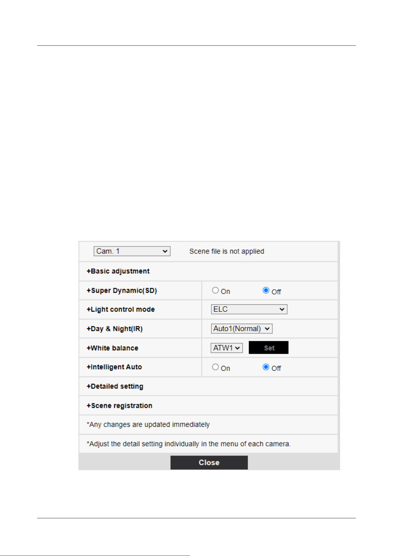
file names displayed in [1:], [2:], [3:], [4:] can be changed.
Characters that cannot be entered:Half-pitch symbol " & ¥
[Load] buttons
The set data selected in [Scene file] is loaded and reflected in the current image.
[Register] buttons
This feature registers combinations of currently displayed image quality-adjusted settings in a
scene file displayed on the [Scene file].
10.4.2 Set the mask area
This section explains how to adjust the light intensity by masking a portion of the screen.
To configure the mask area, set [Super Dynamic] to [Off].
1 Displays the image quality adjustment setting screen.
→10.4 [Image quality] to set the image quality
2 Click + to the left of the [Super Dynamic] to view the Detailed Super Dynamics menu.
10 [Image/Audio] for setting images and sound files
10.4 [Image quality] to set the image quality
333
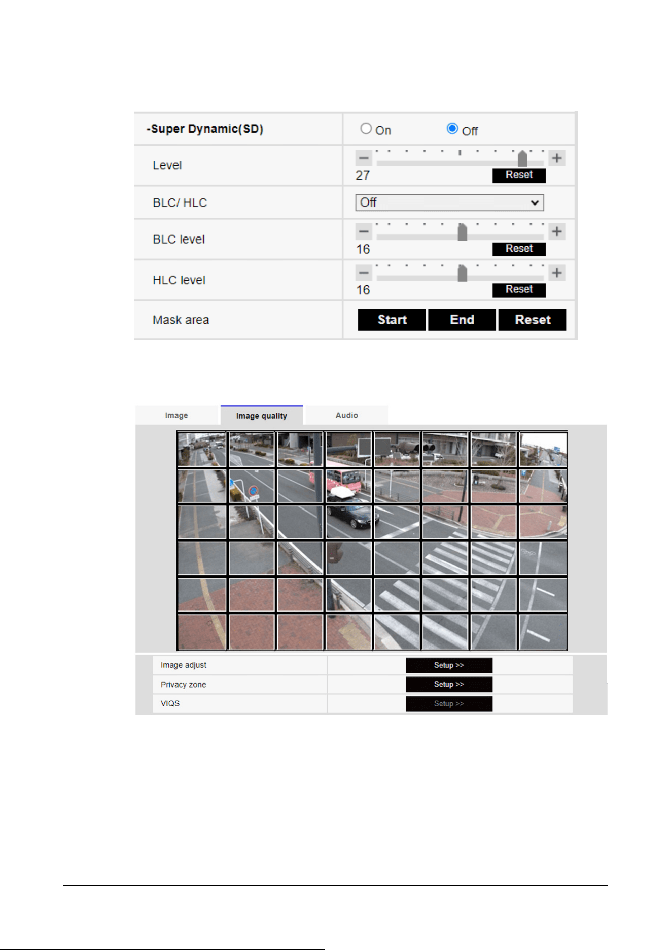
3 Clicking on the [Start] buttons in the [Mask area] displays the boundaries and divides the
images displayed on the [Image quality] tabs into 48 (8×6).
4 Click the split area to be masked to set the frame you clicked to the mask area and turn
white. To release the mask, click the mask area again.
10 [Image/Audio] for setting images and sound files
10.4 [Image quality] to set the image quality
334
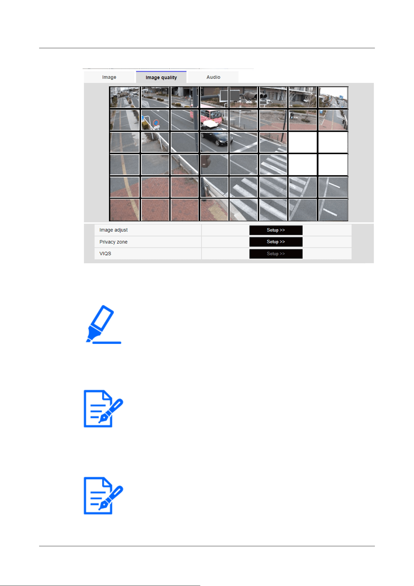
[Important]
・If you change the [Image capture mode] of the [Image] tabs after you configure
the mask area, the mask area may be misaligned. Be sure to check the mask area
settings again.
・If you set EX optical zoom or HD EX optical zoom after setting the mask area,
the mask area may be misaligned. Be sure to check the mask area settings again.
[Note:]
・To cancel all mask areas, press [Reset].
[Note:]
・[MULTI] This function cannot be adjusted when [Image capture mode] is in
Quad/Dual mode.
5 Once the mask area has been set, clicking [Stop] will clear the frame from the images on the
[Image quality] tab.
10.4.3 Adjust the angle of view with the Digital zoom(EX zoom)
10 [Image/Audio] for setting images and sound files
10.4 [Image quality] to set the image quality
335
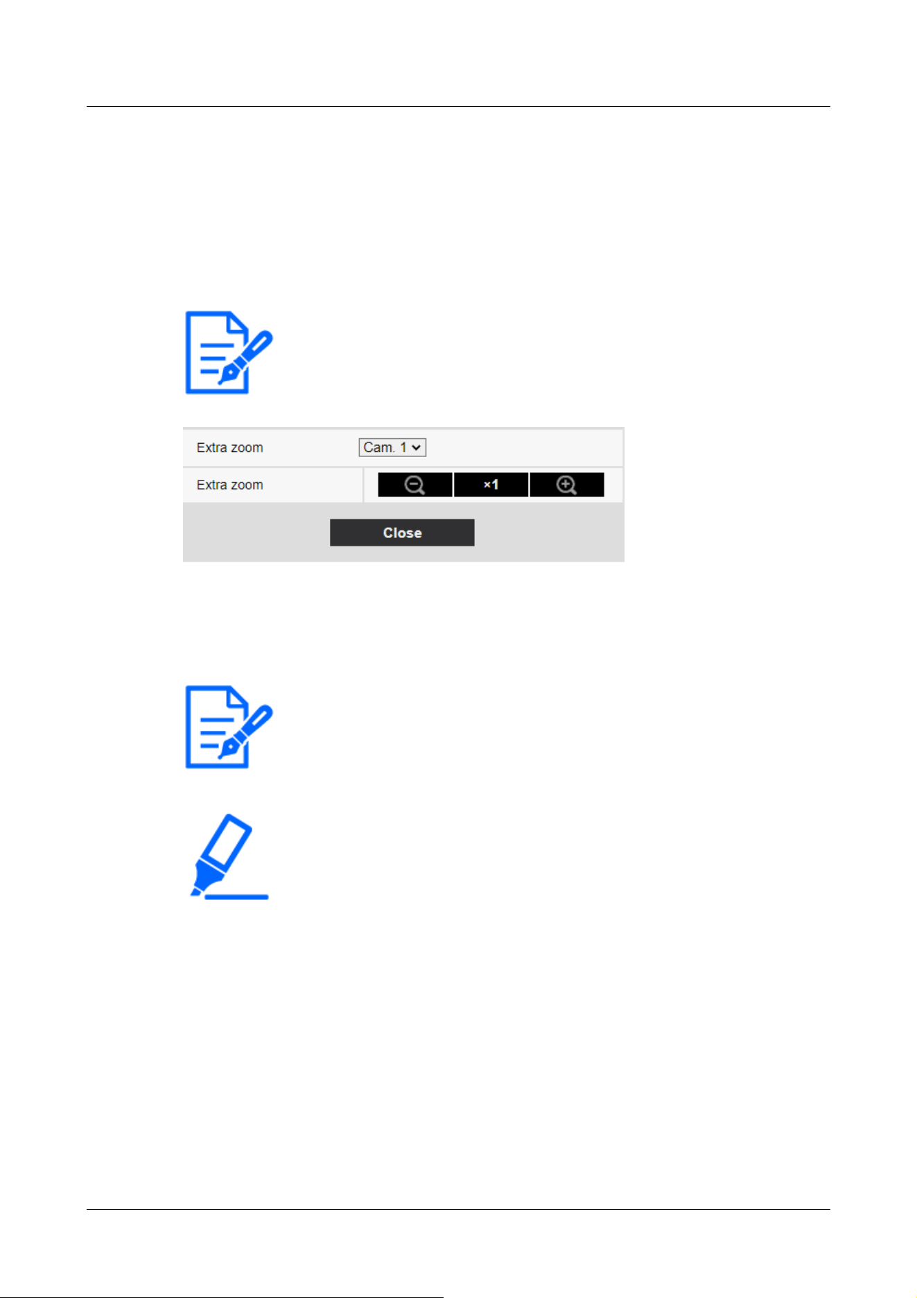
[Note:]
・[MULTI] The camera to adjust the angle of view can be selected.
[Note:]
・The maximum magnification of the EX zoom depends on the model and the [Image
capture mode] you are configuring.
・Refer to the catalog specifications for the maximum magnification of each model.
[Important]
・The extra zoom function may not be activated on the appropriate position if the
setting for the function is performed after the settings for the VIQS area, privacy
zone, VMD area, and SCD area. Therefore, configure each area's settings after
configuring the extra zoom settings.
→10.4.7 Set up VIQS
→10.4.6 Setting the privacy zone (Privacy zone setting screen)
→14.5 [VMD area] for setting motion detection
→14.7 [SCD area] to set up undesired detection
・Set the mask area to 1.0 times the zoom factor. After the EX zoom is set, the
mask position is specified when the zoom (magnification) is 1.0 times.
→10.4.2 Set the mask area
To Advanced Settings in [Digital zoom(Extra zoom)] on the [Image quality] tabs of video pages>>
Click the [Button]. ([Image quality] for setting image quality adjustment, zoom/focus, privacy
zone, VIQS, and lens distortion compensation)
→10.4 [Image quality] to set the image quality
Use EX Zoom to adjust the angle of view of the image.
・Adjust the zoom factor in the [Wide angle] direction.
・Zoom (magnification) 1.0 times.
・Adjust the zoom factor in the [Telescope] direction.
10 [Image/Audio] for setting images and sound files
10.4 [Image quality] to set the image quality
336
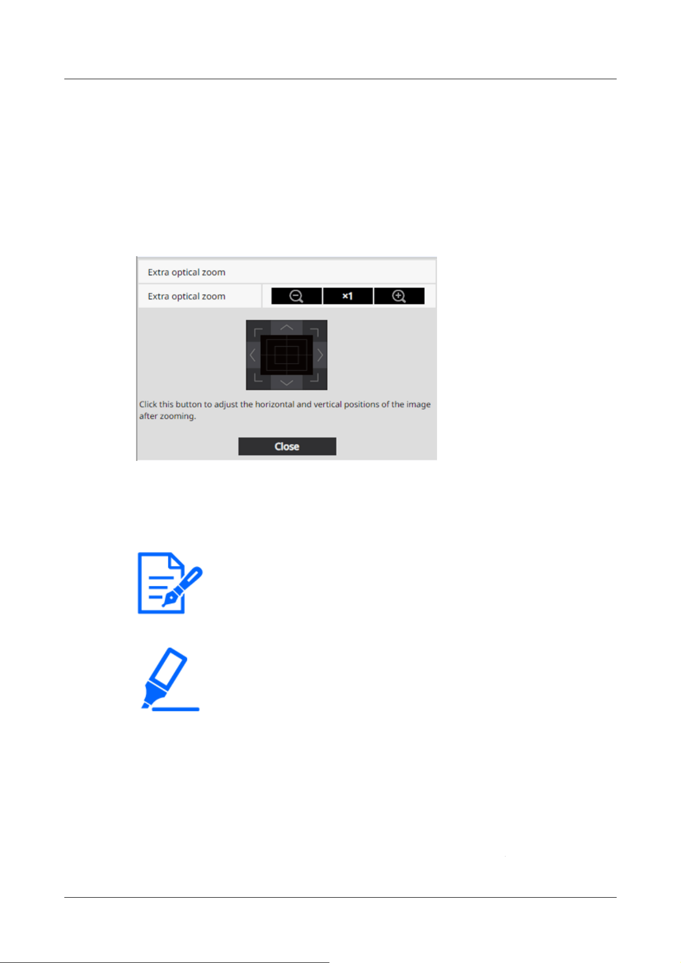
[Note:]
・The maximum magnification of the Ex optical zoom depends on the model and the
[Image capture mode] you are configuring.
・Refer to the catalog specifications for the maximum magnification of each model.
[Important]
・The EX optical zoom function may not be activated on the appropriate position if
the setting for the function is performed after the settings for the VIQS area,
privacy zone, VMD area, and SCD area. Therefore, configure each area's settings
after configuring the EX optical zoom settings.
→10.4.7 Set up VIQS
→10.4.6 Setting the privacy zone (Privacy zone setting screen)
→14.5 [VMD area] for setting motion detection
→14.7 [SCD area] to set up undesired detection
・Set the mask area to 1.0 times the zoom factor. After the EX optical zoom is set,
)
.
.
10.4.4 Adjust the angle of view with the Digital zoom(Ex optical zoom)
To Advanced Settings in [Digital zoom(Extra optical zoom)] on the [Image quality] tabs of video
pages>>Click the [Button]. ([Image quality] for setting image quality adjustment, zoom/focus,
privacy zone, VIQS, and lens distortion compensation)
→10.4 [Image quality] to set the image quality
Use Ex optical zoom to adjust the angle of view of the image.
・Adjust the zoom factor in the [Wide angle] direction.
・Zoom (magnification) 1.0 times.
・Adjust the zoom factor in the [Telescope] direction.
10 [Image/Audio] for setting images and sound files
10.4 [Image quality] to set the image quality
337

the mask position is specified when the zoom (magnification) is 1.0 times.
→10.4.2 Set the mask area
[Note:]
・This function cannot be adjusted when [Image capture mode] is in dual-mode.
[Note:]
・[MULTI] The camera to adjust the angle of view can be selected.
10.4.5 Adjust the zoom/focus
To [Advanced Settings] in [Zoom/Focus Adjustment] of the [Image quality] tabs on the video
pages>>Click the [Button]. ([Image quality] for setting image quality adjustment, zoom/focus,
privacy zone, VIQS, and lens distortion compensation)
→10.4 [Image quality] to set the image quality
Use Zoom and EX optical zoom to adjust the angle of view of the displayed image.
Adjust the focus by moving the lens focus to the optimal position. It can be adjusted manually or
automatically.
10 [Image/Audio] for setting images and sound files
10.4 [Image quality] to set the image quality
338
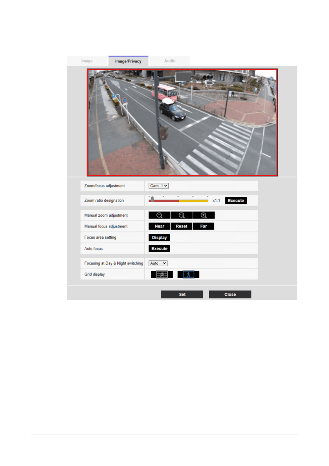
[Zoom ratio designation]
Adjust the zoom and focus simultaneously.
Press the slider bar to zoom in or out the angle adjustment frame in the image.
When you adjust the zoom (magnification) in the "telephoto" direction, only the image adjustment
frame is reduced and you can specify the zoom (magnification) while checking the angle of view
after the zoom is executed.
When the zoom (magnification) is adjusted in the "Wide angle" direction, the image itself is
reduced or the frame for the zoom angle adjustment is enlarged. You can specify the zoom
(magnification) while checking the image size after the zoom is executed.
Adjust the angle of view adjustment frame, and click [Execute] to zoom. Then, automatically
adjust the focus to the object in the center of the window using the auto focus function.
10 [Image/Audio] for setting images and sound files
10.4 [Image quality] to set the image quality
339

[Note:]
・The maximum magnification of the EX zoom depends on the model and the [Image
capture mode] you are configuring.
・Refer to the catalog specifications for the maximum magnification of each model.
・In the [Manual zoom adjustment] Buttons, When you press buttons, [Zoom
ratio designation] cannot be operated. To perform [Zoom ratio designation], click
the "Read" button or click the X1 button on the [Manual zoom adjustment].
・[New X Fixed]If [Stabilizer] is set to [On], the maximum zoom factor is limited.
[Important]
・When EX optical zoom is set with the VIQS area, privacy zone, VMD area, SCD
area, and mask area set, the position is misaligned. Therefore, set the EX optical
zoom and then set each area.
→10.4.7 Set up VIQS
→10.4.6 Setting the privacy zone (Privacy zone setting screen)
→14.5 [VMD area] for setting motion detection
→14.7 [SCD area] to set up undesired detection
→10.4.2 Set the mask area
[Note:]
・One-click on the [Near] or [Far] buttons may appear to have no change in focus
due to trace adjustments. If you want to move the focus position large, press and
hold the button for a long time.
・[New X Fixed]If [Stabilizer] is set to [On], the maximum zoom factor is limited.
[Manual zoom adjustment]
Adjust the zoom manually.
Adjust the zoom factor to 1.0 times in the [Wide Angle] direction.
Zoom (magnification) is 1.0 times.
: Adjust the zoom factor in the [Telescope] direction.
[Manual focus adjustment]
Adjust the focus manually.
[Near]: Adjust the focus to the [Near].
[Reset] returns focus (focus) to its default settings.
[Far]: Adjust the focus to the [Far].
[Focus area setting]
When auto focus is executed, you can specify the object in the frame where you want to adjust the
10 [Image/Audio] for setting images and sound files
10.4 [Image quality] to set the image quality
340

[Note:]
・If you set the focus frame and then change the [Rotate images][Stabilizer] on the
[Basic] tab or [Image capture mode] on the [Image] tab, the focus frame may be
misaligned. Be sure to check the focus frame settings again.
[Important]
・If the [Image capture mode] is [Single source [4:3](30fps mode)], it may take a lot
of time for auto focus to be completed if auto focus is executed while the slow
shutter is running at night while [Maximum shutter] is set to longer than [1/30s].
・If the [Image capture mode] is [Single source [4:3](25fps mode)], it may take a lot
of time for auto focus to be completed if auto focus is executed while the slow
shutter is running at night while [Maximum shutter] is set to longer than [1/25s
max.].
・The focus may not be adjusted automatically in the following locations or object.
In this case, adjust the focus manually.
Be a big move
Large variation in illumination
Low illuminance
Be too bright or too reflective
Over the window
Dome covers are prone to contamination.
White walls are less dark.
focus.
If not, adjust the focus to the object in the center area of the window.
[Display]: Displays the auto focus frame on the setup window. The default setting is displayed in
the center area of the screen. Drag the mouse on the image and specify the area where you want
to adjust the focus. When you are finished, press [Register].
When the [Display] button is clicked, the [Reset] and [Register] buttons are displayed.
[Reset]: Returns the frame setting to the default position.
[Register]: Saves the set frame. Clicking to automatically adjust focus to the object in the
specified area
I do.
[Auto focus]
When [Execute] is clicked, the auto focus function is activated to automatically adjust the focus to
the object in the center of the window.
10 [Image/Audio] for setting images and sound files
10.4 [Image quality] to set the image quality
341

Flicker fiercely
・When the image is switched from color to black and white in the near infrared
region, the focus may shift due to the optical characteristics. If [Focusing at Day
& Night switching] is set to [Auto] or [Preset], the camera can focus automatically
(it does not support the lighting change after the focus operation is completed).
[Important]
・If the focus cannot be adjusted automatically when switching between color and
black and white images in the [Auto] setting, set it to [Preset] or [Fix] and adjust
the focus manually.
[Focusing at Day & Night switching]
Select the focus adjustment method when switching between color image and black-and-white
image from the following.
For details, refer to our technical information website <Control No. C0315>.
[Auto]:The focus is automatically adjusted when the color/black-and-white settings are changed
from the focus-adjusted image. When the original color/black/white status is changed, the focus
position is returned to the last one. If the image cannot be adjusted with a black-and-white image,
the image may be re-adjusted with a color image and then switched to a black-and-white image.
[Preset]:When switching between color image and black-and-white image, the preset is moved to
the specified focus position. In the preset position, the color image or black-and-white image
automatically stores the focus position set last.
[Fix]:After adjusting the focus automatically or manually, fix the position.
[Grid display]
You can switch on/off the grid view that can be used to adjust the position of the machine when
using Extension software. For adjusted sizes for each Extension software, please refer to our
Technical Information website<Control No.: C0320>.
[Close] buttons
Close the Zoom/Focus dialog box.
10.4.6 Setting the privacy zone (Privacy zone setting screen)
In the Video/Audio [Image quality] tabs to [Privacy zone] Advanced Settings>>Click the [Button].
→10.4 [Image quality] to set the image quality
10 [Image/Audio] for setting images and sound files
10.4 [Image quality] to set the image quality
342

[Note:]
・Refer to the catalog specifications for the number of privacy zones that can be set
for each model.
・[PTZ] The Privacy Zone function does not work during initial operation or
position refresh immediately after the power supply is turned on.
・[PTZ] Depending on the orientation of the camera (especially the tilt angle of
45° to 90°) or the magnification factor, you may see where you want to hide.
Be sure to check after setting.
・[PTZ] Reset the Privacy Zone when you change the method of fixing the camera.
If there are areas in the shooting location (image) that you do not want to display, do not display
those areas as privacy zones.
The privacy zone function of each camera is described below.
New X Fixed Cameras
10 [Image/Audio] for setting images and sound files
10.4 [Image quality] to set the image quality
343
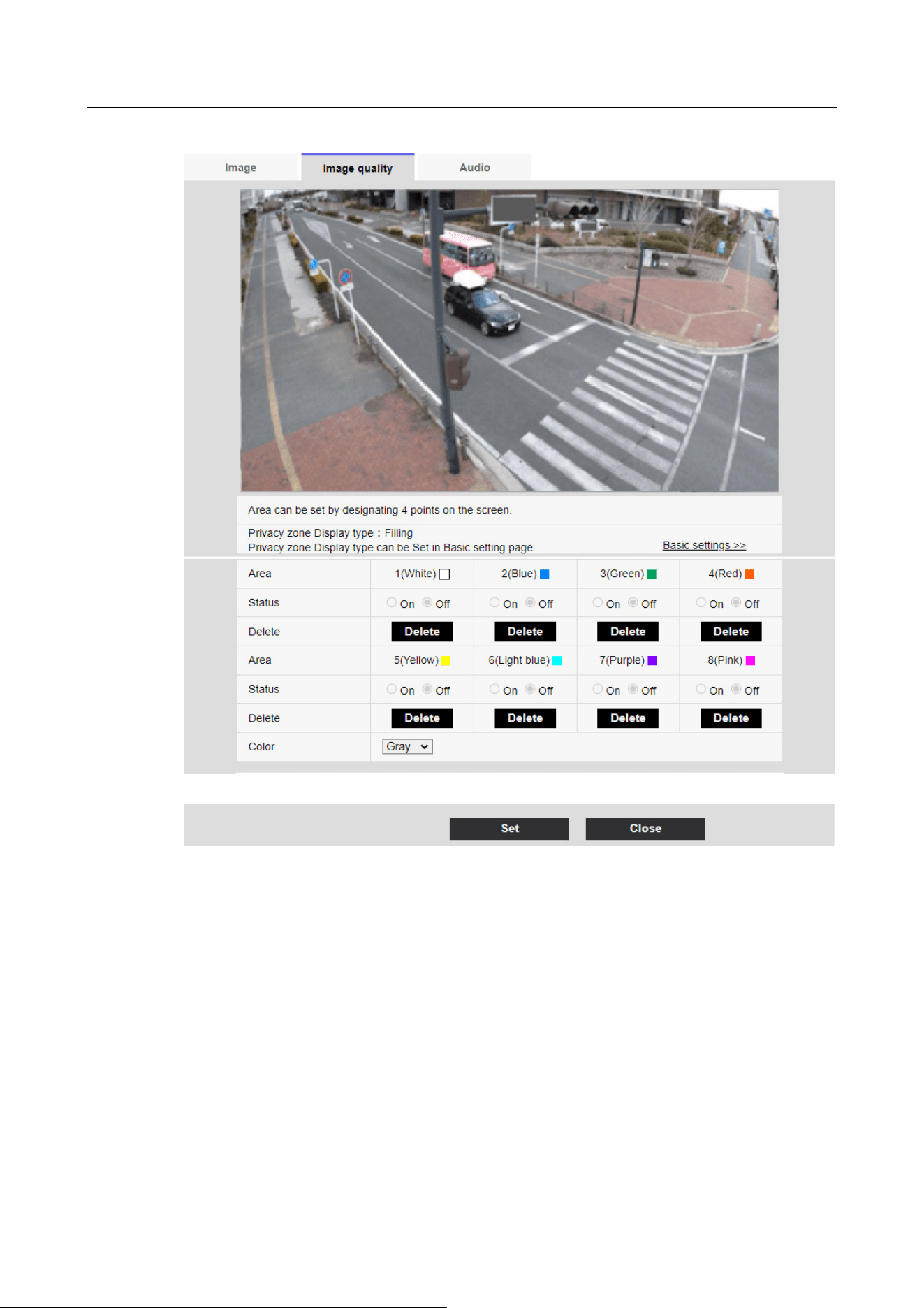
Compact Dome cameras, Corner cameras, U-series camera with edge AI
10 [Image/Audio] for setting images and sound files
10.4 [Image quality] to set the image quality
344
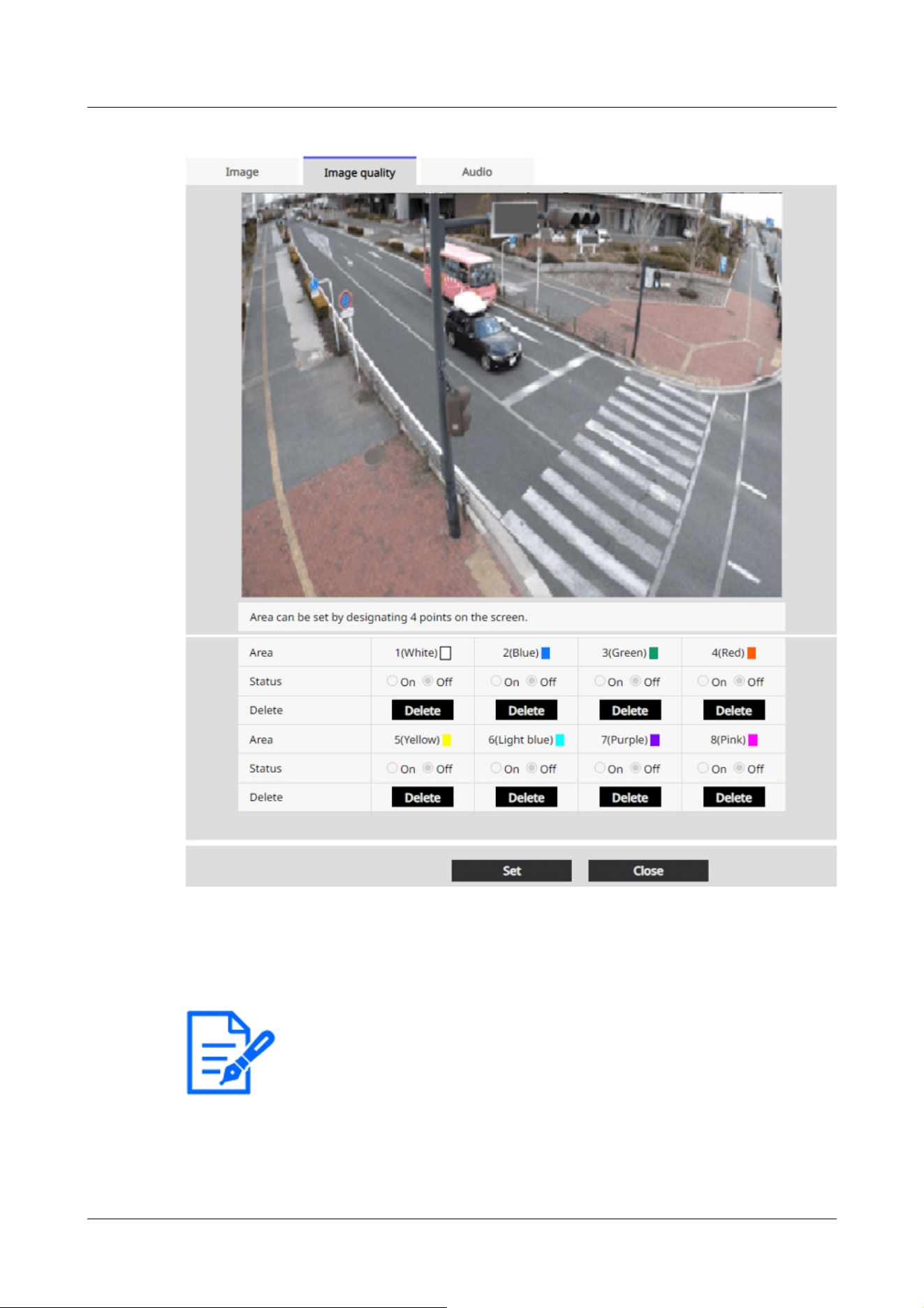
[Note:]
・The privacy zone should be wider than the hidden object.
・[CompactU] When you drag the desired range with the mouse, it is set as the
privacy zone.
[Area]
This is set as the privacy zone by specifying four vertices on the image. Each zone can also be set
in overlap. The zones are set in order from Area 1.
[Status]
10 [Image/Audio] for setting images and sound files
10.4 [Image quality] to set the image quality
345
[Note:]
・[Color] can be set when [Privacy zone display format] is set to [Block] in the basic
settings window.
[Note:]
・[Intensity of mosaic] can be set when [Privacy zone display format] is set to
[Blurring] in the basic settings window.
[Important]
・If you configure a privacy zone and then change the [Image capture mode] and
[Basic] tab [Image rotation] on the [Image] tab, the privacy zone may be
misaligned. Be sure to check the privacy zone settings again.
・Setting the privacy zone and then setting the EX zoom may cause the privacy
zone to be misaligned. Be sure to check the privacy zone settings again.
・If the privacy zone is set when lens distortion compensation is enabled, it may be
misaligned. In such a case, return the lens distortion compensation to [0] and set
the privacy zone. Then, set the lens distortion compensation again.
・[New X Fixed]If you configure the Privacy Zone area with a Image capture size of
1920x1080 or less, the Privacy Zone may be offset.Be sure to check the privacy
zone settings again.
Use [On]/[Off] to set whether the privacy zone is displayed.
[On]:Displays the privacy zone.
[Off]:Privacy zone is not displayed.
[Collar]
You can select the color of the Privacy Zone to be displayed in the video area from the following.
[Gray]/[Red]/[Blue]/[Green]/[White]/[Black]
[Intensity of mosaic]
You can select how to mosaic the Privacy Zone to be displayed in the video area.
[High]/[Middle]/[Low]
[Delete] buttons
Click the button on the area to delete the button to delete the zone.
[Close] buttons
Close the Privacy Zone Settings window.
10 [Image/Audio] for setting images and sound files
10.4 [Image quality] to set the image quality
346
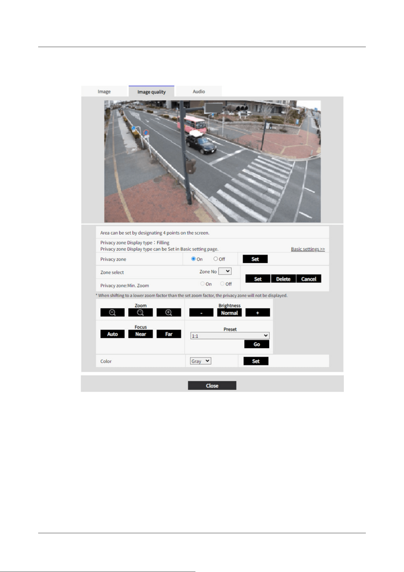
AI Outdoor IR Bullet Camera (X series)
AI Outdoor IR Bullet Camera (S series)
10 [Image/Audio] for setting images and sound files
10.4 [Image quality] to set the image quality
347
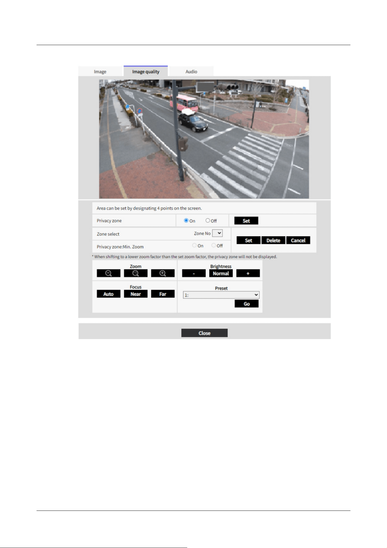
PTZ cameras
10 [Image/Audio] for setting images and sound files
10.4 [Image quality] to set the image quality
348
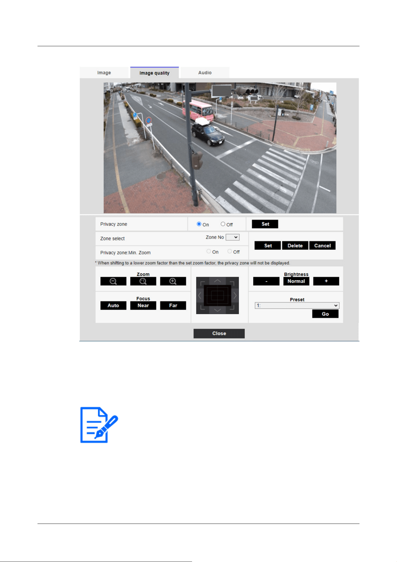
[Note:]
・[Rapid PTZ-8M(4K)][AI Outdoor IR BulletX-8M][AI Outdoor IR BulletS-8M]
When [Privacy zone] is set to [On], the frame rate is limited to the maximum
12.5fps when in max 15fps(25fps mode).
[Privacy zone]
Select the display format of the privacy zone from the following.
[On]:Display in gray
[Off]:Not displayed.
[Zone select]
Click [▼] on the [Zone No] and select the number of zones you want to set.
The [*] mark to the right of the zone number indicates that a privacy zone has already been set.
This is set as the privacy zone by specifying four vertices on the image.
10 [Image/Audio] for setting images and sound files
10.4 [Image quality] to set the image quality
349

[Note:]
・The privacy zone should be set broadly for objects that you want to hide.
It is recommended to set the zone between 1 and 3 times the zoom magnification
to increase the zone accuracy on the wide angle side.
[Note:]
・If enabled, the privacy zone will not be displayed if you move to a magnification
lower than the set zoom magnification.
Once the position has been determined, press [Set].
To delete a registered zone, specify the zone number and press [Delete].
To cancel setting or deletion, press [Cancel].
[Privacy zone:Min. Zoom]
Use [On] or [Off] to toggle the smallest zoom in zones.
[On]:The current zoom position is saved.
[Disable]:The zoom position is saved as X1 times. The privacy zone is always displayed regardless
of the zoom position.
[Zoom] buttons
:Adjust the zoom factor in the [Telescope] direction.
:Zoom (magnification) 1.0 times.
:Adjust the zoom factor in the [Wide angle] direction.
[Focus] buttons
[Auto]:Automatically adjust focus.
[Near]:Adjust the focus (focus) to [Near].
[Far]:Adjust the focus (focus) to [Far].
Control pad/button
Left-click the pads and buttons to adjust the horizontal and vertical position of the image (pan
tilt).
The faster the camera operates, the faster the outside of the pad is clicked.
You can also drag and adjust the mouse. Zoom and focus by right-clicking.
Clicking on the upper half of the pad in the upper and lower directions will zoom in the telephoto,
and clicking on the lower half will zoom in the wide angle. Clicking on the left half in the left and
right directions will bring the focus (focus) close to you, and clicking on the right half will bring it
far away. You can also adjust the zoom by using the mouse wheel.
[Brightness] buttons
10 [Image/Audio] for setting images and sound files
10.4 [Image quality] to set the image quality
350

[Important]
・If you configure a privacy zone and then change the [Image capture mode] and
[Basic] tab [Image rotation] on the [Image] tab, the privacy zone may be
misaligned. Be sure to check the privacy zone settings again.
・[AI Outdoor IR BulletX]If you configure the Privacy Zone area with a Image
capture size of 1920x1080 or less, the Privacy Zone may be offset.Be sure to
check the privacy zone settings again.
It can be adjusted from 0 to 255. Click the [Light (+)] button to brighten the image. Click the
[Black (-)] button to darken the image. Press [Normal] to return to the default settings.
Move button
Select the preset position from the pull-down menu and click the [Move] button to move the
camera's orientation to the preset position registered beforehand. [H] next to the number
indicates the home position. Select [HomePosition] to move the orientation of the camera to the
home position.
→11.2.1 Set the preset position (preset position setting screen)
→11.1 [Cam. Function] for setting the operation of cameras
If [Preset ID (0 – 9,A – Z)] is registered, the position name is displayed next to the number.
[Close] buttons
Click this button to close the Privacy Zone Settings window.
Multi-directional camera
10 [Image/Audio] for setting images and sound files
10.4 [Image quality] to set the image quality
351
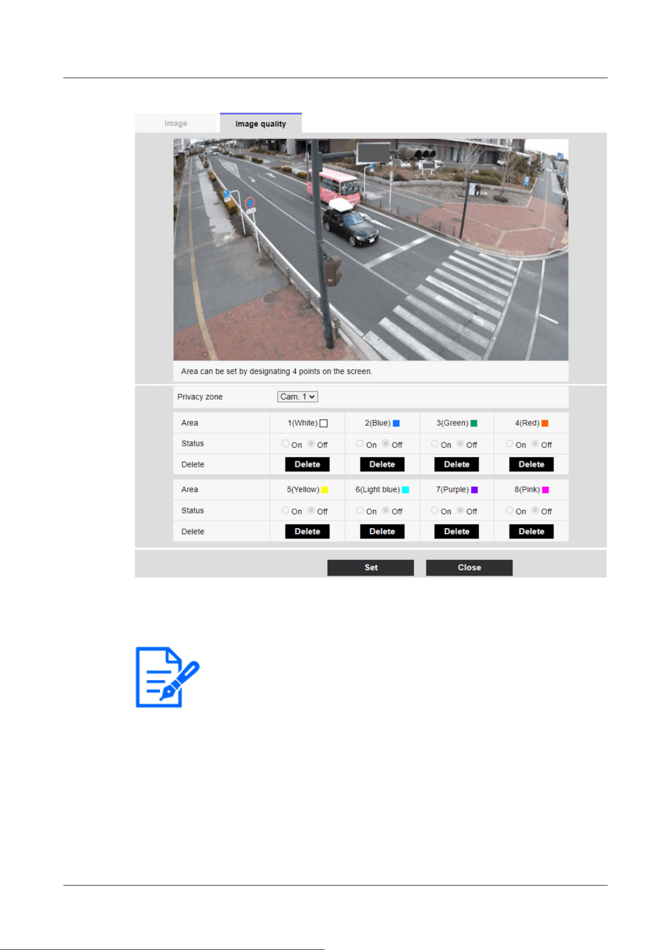
[Note:]
・When [Image capture mode] is in Quad/Dual mode, the camera cannot be selected.
[Camera selection]
Select the camera to set the privacy zone from each camera.
[Area]
This is set as the privacy zone by specifying four vertices on the image. Each zone can also be set
in overlap. The zones are set in order from Area 1.
10 [Image/Audio] for setting images and sound files
10.4 [Image quality] to set the image quality
352

[Note:]
・The privacy zone should be wider than the hidden object.
・When [Image capture mode] is in Quad/Dual mode, any four points across the
cameras cannot be specified for the area.
[Important]
・If you configure a privacy zone and then change the [Image capture mode] and
[Basic] tab [Image rotation] [Stabilizer] on the [Image] tab, the privacy zone may
be misaligned. Be sure to check the privacy zone settings again.
・Setting the privacy zone and then setting the EX zoom may cause the privacy
zone to be misaligned. Be sure to check the privacy zone settings again.
・If the privacy zone is set when lens distortion compensation is enabled, it may be
misaligned. In such a case, return the lens distortion compensation to [0] and set
the privacy zone. Then, set the lens distortion compensation again.
[Status]
Use [On]/[Off] to set whether the privacy zone is displayed.
[On]:Displays the privacy zone.
[Off]:Privacy zone is not displayed.
[Delete] buttons
Click the button on the area to delete the button to delete the zone.
[Close] buttons
Close the Privacy Zone Settings window.
10.4.7 Set up VIQS
To Advanced Settings on the [Image quality] tabs of Video/Audio pages [VIQS]>>Click the
[Button].
→10.4 [Image quality] to set the image quality
What is VIQS?
Abbreviation for Variable Image Quality on Specified Area. This function enables you to change
the image quality in the specified area.
Image quality in the range specified in the shooting location (image) can be made high quality for
easy viewing. Image quality outside the specified range is low and image data size can be suppressed.
10 [Image/Audio] for setting images and sound files
10.4 [Image quality] to set the image quality
353

[Note:]
・VIQS covers only H.265 (or H.264) images.
・Up to eight VIQS areas can be set.
・After [Stream] is set to [On], press [Execute] to view the images after VIQS is
set.
You can also view the H.265 (or H.264) image on a live image page.
・The VIQS function cannot be used in the following cases.
-When [Stream(1)] [Smart VIQS] is set to [On(High)] or [On(Low)]
When-[Smart P-picture control] is set to [On]
The VIQS function of each camera is described below.
Fixed cameras
10 [Image/Audio] for setting images and sound files
10.4 [Image quality] to set the image quality
354
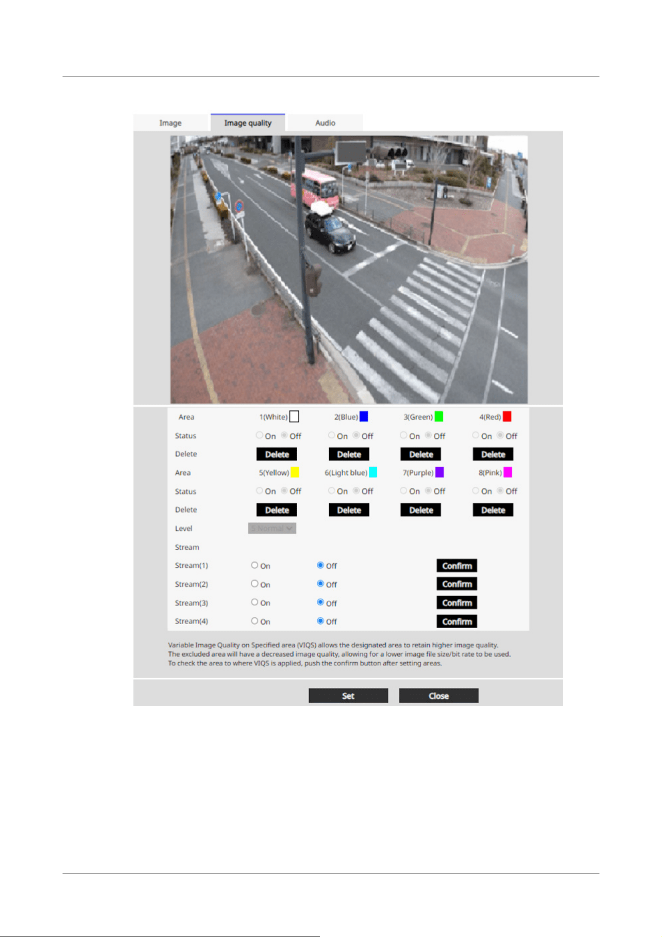
[Area]
When the VIQS area is selected in the image, it is set from Area 1.
[Status]
Set the VIQS area with [On] and [Off].
[On]:Set the VIQS area.
[Off]:Do not configure the VIQS area.
10 [Image/Audio] for setting images and sound files
10.4 [Image quality] to set the image quality
355

[Important]
・If you set the VIQS setting to [On] and then change the [Image capture mode]
and [Basic] tab [Image rotation][Stabilizer] on the [Image] tab of the video and
audio pages, the VIQS area may be misaligned. Be sure to reconfirm the VIQS
settings.
[Note:]
・Refer to the following procedure for setting the VIQS area.
→10.4.8 Set up the VIQS area
・If the [Stream transmission] of the relevant stream is set to [Off], you cannot
press the [Execute] buttons for selecting the stream.
[Delete] buttons
Click the area button to delete the area frame.
[Level]
Sets the level difference between the quality in the specified range and the quality outside the
specified range. The larger the level difference, the lower the image quality outside the specified
range and the smaller the image data size.
[0:Minimum]/1/2/3/4/[5:standard]/6/7/8/[9:maximum]
Stream selection
Use [On]/[Off] to specify whether the VIQS function is enabled for images delivered to streams.
The [Execute] buttons allow you to view images of individual streams.
PTZ camera, AI Outdoor IR Bullet Camera
Select the position for which you want to set the VIQS area and press [Start] to open the VIQS
area setting window for the selected position.
You can specify the VIQS area on the displayed setting screen.
VIQS area setting
10 [Image/Audio] for setting images and sound files
10.4 [Image quality] to set the image quality
356
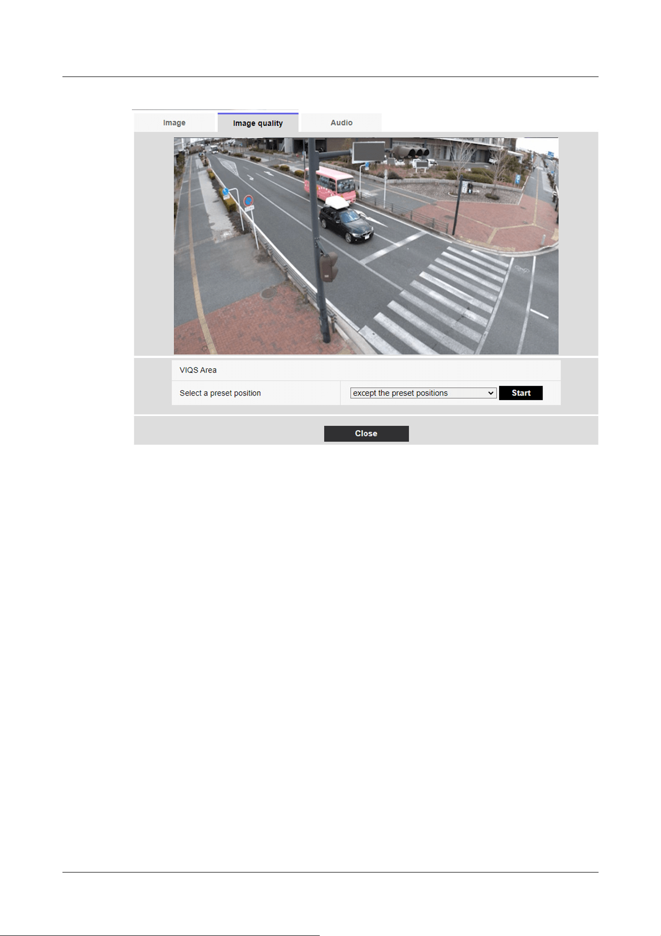
[Select a preset position]
Select the preset position number for which you want to configure the VIQS area, and then press
[Start] to configure the VIQS area.
Select [except the preset positions] to set the VIQS area other than the preset position.
[Close] buttons
Click to close the VIQS Settings window.
10 [Image/Audio] for setting images and sound files
10.4 [Image quality] to set the image quality
357
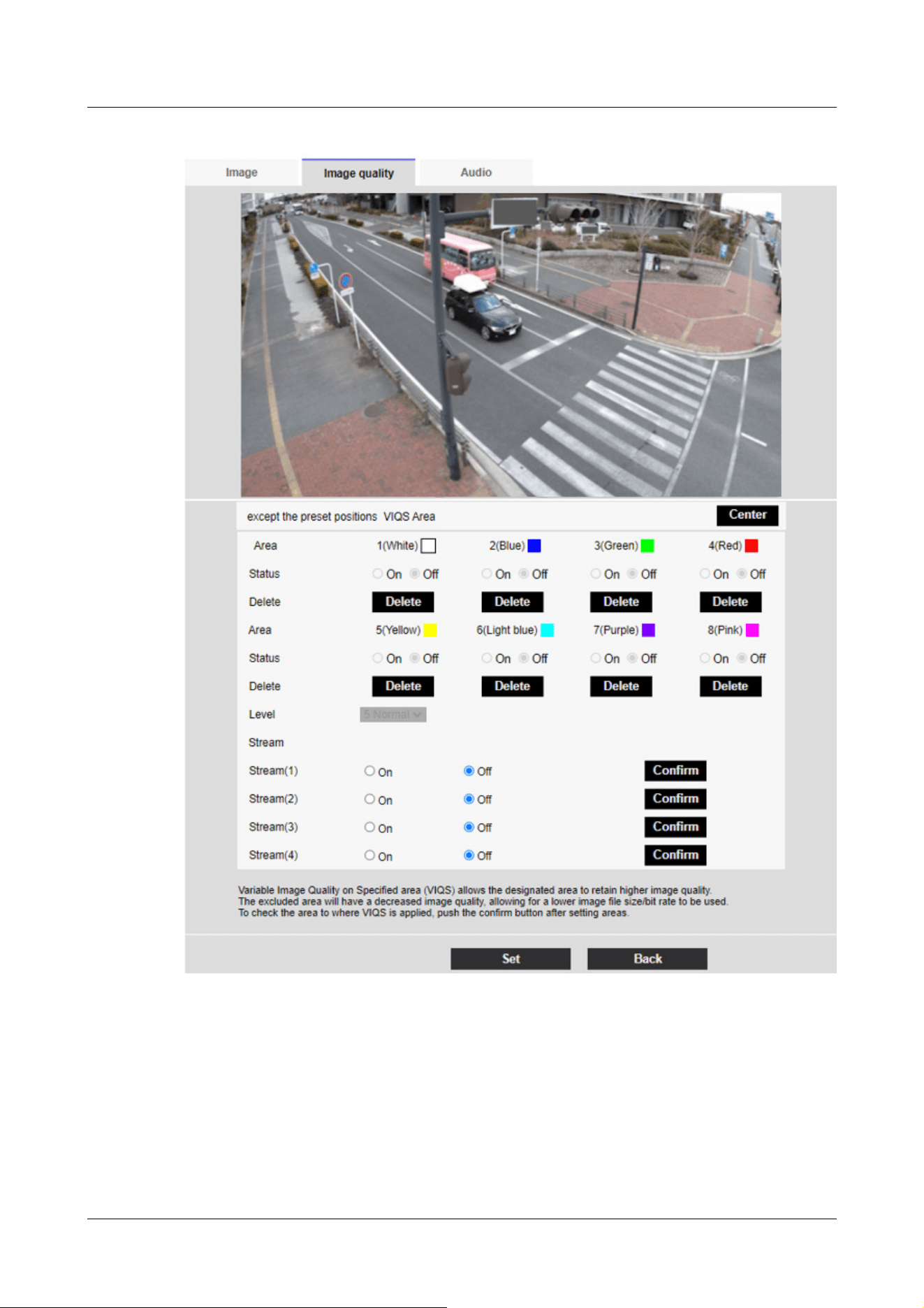
[Area]
When the VIQS area is selected in the image, it is set from Area 1.
[Center] button
When clicked, the center is selected as the VIQS area and set to the [1(White)] of the [Area].
[Status]
Set the VIQS area with [On] and [Off].
10 [Image/Audio] for setting images and sound files
10.4 [Image quality] to set the image quality
358

[Important]
・If you set the VIQS setting to [On] and then change the [Image capture mode]
and [Basic] tab [Image rotation] on the [Image] tab of the video and audio pages,
the VIQS area may be misaligned. Be sure to reconfirm the VIQS settings.
[Note:]
・Refer to the following procedure for setting the VIQS area.
→10.4.8 Set up the VIQS area
・If the [Stream transmission] of the relevant stream is set to [Off], you cannot
press the [Execute] buttons for selecting the stream.
[On]:Set the VIQS area.
[Off]:Do not configure the VIQS area.
[Delete] buttons
Click the area button to delete the area frame.
[Level]
Sets the level difference between the quality in the specified range and the quality outside the
specified range. The larger the level difference, the lower the image quality outside the specified
range and the smaller the image data size.
[0:Minimum]/1/2/3/4/[5:standard]/6/7/8/[9:maximum]
Stream selection
Use [On]/[Off] to specify whether the VIQS function is enabled for images delivered to streams.
The [Execute] buttons allow you to view images of individual streams.
Multi-directional camera
10 [Image/Audio] for setting images and sound files
10.4 [Image quality] to set the image quality
359
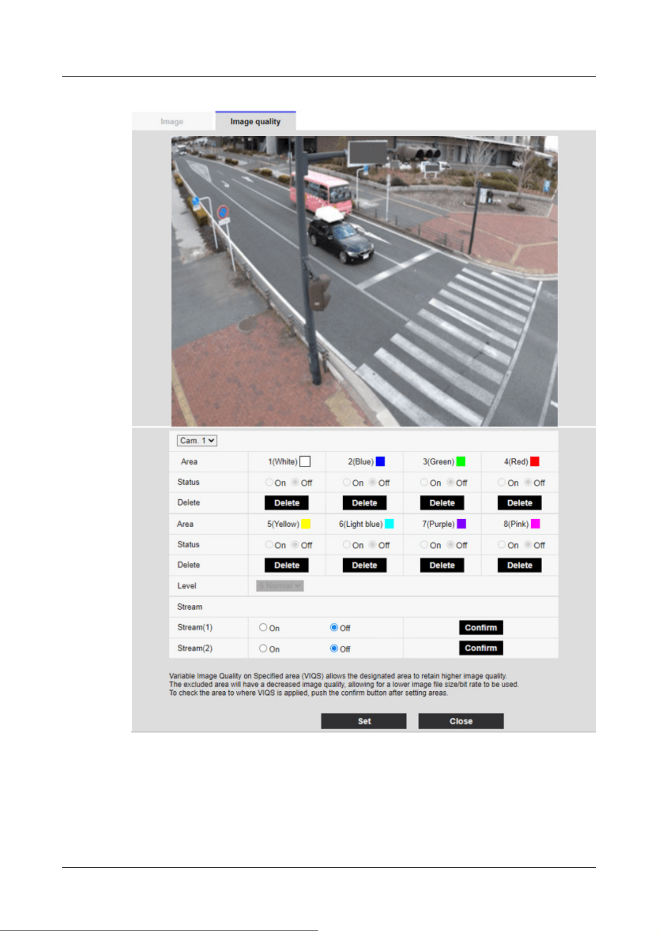
[Camera selection]
Select the camera to set the VIQS area from each camera.
10 [Image/Audio] for setting images and sound files
10.4 [Image quality] to set the image quality
360

[Note:]
・When [Image capture mode] is in Quad/Dual mode, the camera cannot be selected.
[Important]
・If you turn on the VIQS setting and then change the [Image capture mode] and
[Basic] tab [Image rotation] on the [Image] tab of the video and audio pages, the
VIQS area may be misaligned. Be sure to check the VIQS settings again.
[Note:]
・Refer to the following procedure for setting the VIQS area.
→10.4.8 Set up the VIQS area
・If the [Stream transmission] of the relevant stream is set to [Off], you cannot
press the [Execute] buttons for selecting the stream.
[Area]
When the VIQS area is selected in the image, it is set from Area 1.
[Status]
Set the VIQS area with [On] and [Off].
[On]:Set the VIQS area.
[Off]:Do not configure the VIQS area.
[Delete]
Click the button of the area to delete to delete the area frame.
[Level]
Sets the level difference between the quality in the specified range and the quality outside the
specified range. The larger the level difference, the lower the image quality outside the specified
range and the smaller the image data size.
[0:Minimum]/1/2/3/4/[5:standard]/6/7/8/[9:maximum]
Stream selection
Use [On]/[Off] to specify whether the VIQS function is enabled for images delivered to streams.
The [Execute] buttons allow you to view images of individual streams.
10.4.8 Set up the VIQS area
Set the VIQS area as follows.
1 Drag the mouse on the image and specify the area. You can specify up to 8 areas.
10 [Image/Audio] for setting images and sound files
10.4 [Image quality] to set the image quality
361
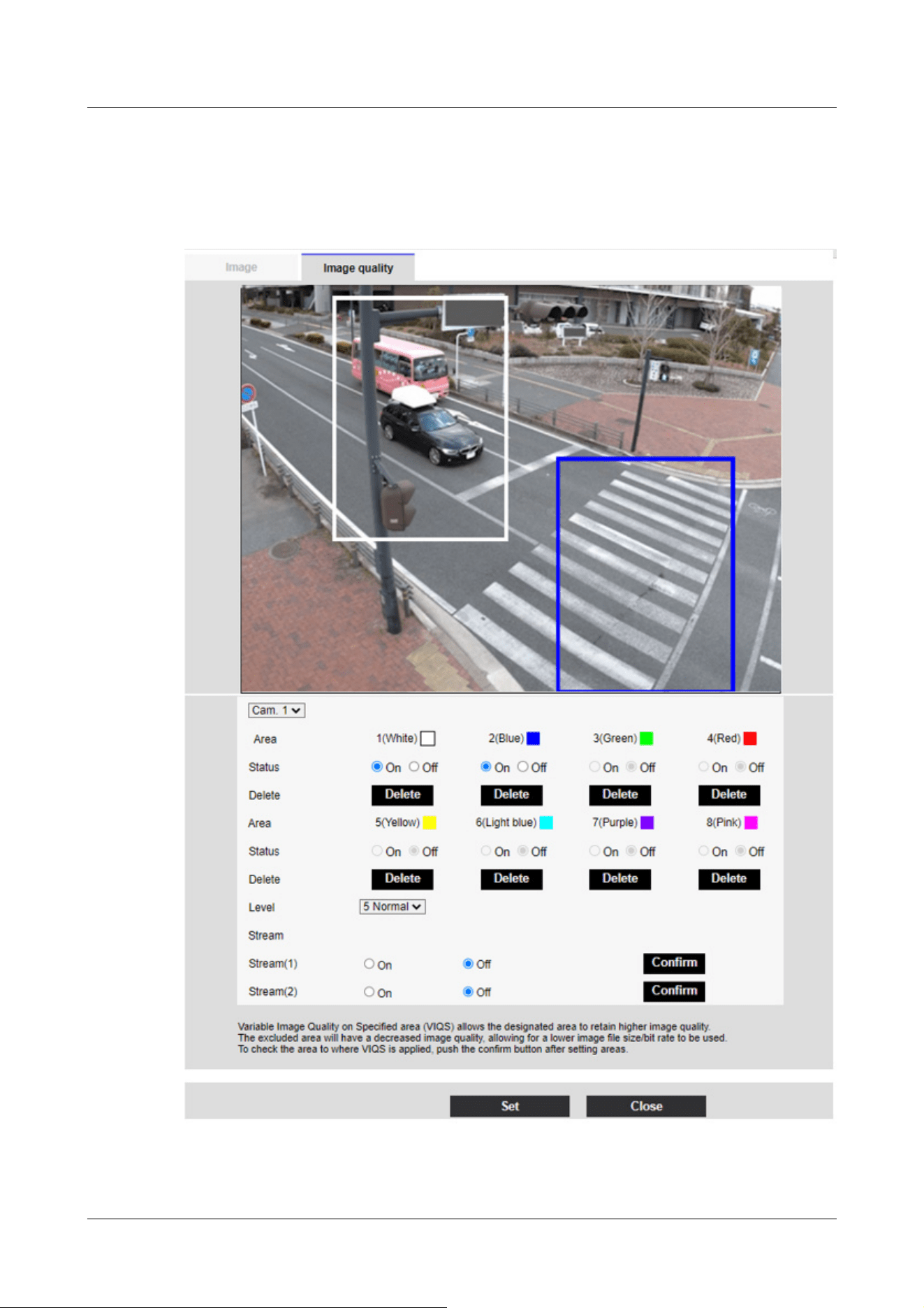
The specified location is set to Area [1(White)], and a frame is displayed.
Areas are set from the first to the first area number. The color next to the area number
indicates the corresponding color of the frame.
2 Sets the level difference between the quality in the specified range and the quality outside the
10 [Image/Audio] for setting images and sound files
10.4 [Image quality] to set the image quality
362

[Important]
・If you do not press the [Set] buttons, the settings will not be confirmed.
・Visual image after VIQS setting can be confirmed by displaying the H.265 (or
H.264) image on the live image page or by pressing [Execute] on the [Stream].
・The current output bit rate varies depending on the subject. Check the actual
subject during operation.
・The larger the specified range, the larger the output bit rate. Check the current
output bit rate and determine the size of the area.
[Note:]
・[MULTI] Only Multi-directional cameras can be selected for [Camera selection].
・[MULTI] When [Image capture mode] is in Quad/Dual mode, the camera cannot
be selected.
specified range. The larger the level difference, the lower the image quality outside the
specified range and the smaller the image data size.
3 On/Off selects whether to enable the VIQS function on the delivered image of each stream.
4 Press [Set].
The settings are reflected on the computer. To delete the setting area, click [Delete] in the
area to delete.
5 Press [Execute].
The streams with the [Execute] buttons are displayed. The current output bit rate can be
checked when another window opens for approximately 3 seconds.
10.4.9 Set the lens distortion compensation
To Advanced Settings on the [Image quality] tabs of Video/Audio pages [Lens distortion
compensation]>>Click the [Button].
→10.4 [Image quality] to set the image quality
You can use lens distortion correction to correct the distortion.
The correction amount can be adjusted.
The degree of distortion compensation depends on the zoom factor. Adjust the image angle with
the zoom setting and then set the lens distortion compensation.
[Camera selection]
Select the camera to adjust the lens distortion compensation from each camera.
[Lens distortion compensation]
10 [Image/Audio] for setting images and sound files
10.4 [Image quality] to set the image quality
363

[Note:]
・When EX optical zoom is used, lens distortion compensation does not work.
・When lens distortion compensation is set to ON, all cameras are set to ON.
Turning on lens distortion compensation may lower the frame rate.
・[New X Fixed]If [Shake] is set to [On], [Lens distortion compensation] cannot be
used.
・[New X Fixed]If you set [Privacy Zone Display Format] to [Blurring], you cannot
use [Lens distortion compensation].
[Note:]
・Images and sound are not synchronized. Therefore, there may be a slight
deviation between the image and sound.
・Depending on the network environment, audio may be interrupted.
You can switch the lens distortion compensation ON/OFF.
Move the slider bar in the [+] direction or [-] direction to adjust the image distortion.
Press [Reset] to return to the default settings.
10.5 [Audio] for setting sound
Click on the [Audio] tabs of the video and audio pages. Refer to the following how to display and
operate the Advanced menu.
→5.1 How to display
→5.2 How to operate
Here, the settings related to sound are made.
Voice input
[Mic select]
Select the microphone to use when receiving audio data.
[Internal]:Use the camera's built-in microphone.
[External]:Use the audio input from the microphone/line input jack.
[Mic input volume]
Set the volume of sound input to the computer. This setting is reflected in the volume of sound
(listening) on the computer and the volume at [Audio recording].
[Mic strength]/[Mic in progress]/[Microphone weak]:Set the volume when the sound is entered
into the camera by microphone.
10 [Image/Audio] for setting images and sound files
10.5 [Audio] for setting sound
364

[Note:]
・When [Mic select] is set to [Internal], the Line High, Line Medium, and Line Low
cannot be selected.
[Note:]
・The howling may occur depending on the operating conditions. In this case, do
not allow the sound output from the PC to enter the microphone of the PC.
・[Audio recording] cannot be used when [Audio transmission mode] is set to
[Interactive(Half-duplex)].
・When using live picture pages, use HTTPS to access live picture pages.
[Line Strength]/[In Line]/[Line Weak]:Set the volume when the sound is inputted to the camera
line.
[AGC (audio)]
The earpiece sound is automatically amplified and adjusted to the appropriate volume. Select the
degree of amplification from High/Middle/Low. When set to [High], it is easier to hear a small
sound, but it may be heard as a noise. If you are concerned about noise, set it to [Middle] or
[Low]. This setting is linked to the [Audio recording] volume.
[Max bit rate]
Set the bit rate of sound compression.
[G.726]:16kbps/ 32kbps
[G.711] : 64 kbps (cannot be changed)
[AAC‑LC]:64kbps/ 96kbps/ 128kbps
Voice delivery
[Audio transmission mode]
Set the communication mode for sending/receiving voice data between the computer and PC from
the following.
[Off]:Audio data is not transmitted or received between the computer and the PC.
[Mic input]:The PC receives audio data from the computer. You can hear sound together with
images on a PC. Images and sound are not synchronized.
[Audio output]:The audio data from the PC is transmitted to the computer. Audio can be played
through a speaker connected to the computer.
[Interactive(Half-duplex)]:You can make both listening and outgoing calls. However, audio cannot
be sent/received simultaneously.
[Interactive(Full-duplex)]:You can both listen and talk at the same time.
10 [Image/Audio] for setting images and sound files
10.5 [Audio] for setting sound
365

[Note:]
・The shorter the call interval, the shorter the delay time. Increasing the value
lengthens the delay time but reduces speech interruption. Change the settings
depending on your network environment.
・If [AAC-LC] is selected in [Audio input encoding format], [Mic input interval
(Camera to PC)] cannot be selected.
[Note:]
・The smaller the call interval, the shorter the delay time. Increasing the value
lengthens the delay time but reduces speech interruption. Change the settings
depending on your network environment, the performance of your PC, and the
usage status of applications other than web browsers.
・When multiple users are accessing the computer, the sound may be temporarily
interrupted or the noise may be output. Increasing the transmission interval can
reduce speech interruptions and noise.
・Sound may not be output depending on your network environment and settings.
[Note:]
・The call stops after the set time after the start of the call. If you want to make
another call, click the call button.
[Mic input interval (Camera to PC)]
Select the voice reception interval from the following.
[20ms]/ [40ms]/ [80ms]/ [160ms]
[Audio output volume (PC to Camera)]
Sets the volume to which the sound from the PC is played from the computer.
[High]/[Middle]/[Low]
[Audio output interval (PC to Camera)]
Select the voice transmission interval from the following.
[160ms]/ [320ms]/ [640ms]/ [1280ms]
[Audio output duration]
You set the maximum time for one call.
[1min]/ [2min]/ [3min]/ [5min]/ [10min]/ [20min]/ [30min]/ [1h]
[Audio output port (PC to Camera)]
Enter the destination port number (the port number on the camera to send voice to the computer).
10 [Image/Audio] for setting images and sound files
10.5 [Audio] for setting sound
366

[Note:]
・The Destination port number entered in [Audio output port (PC to Camera)] is
used only if [Transmission type] is set to [Unicast port (MANUAL)]. If [Stream
transmission] has selected [Off] or [Transmission type] [Unicast port (AUTO)] or
[Multicast], you do not need to enter the Destination port number.
[Note:]
・Only AAC-LC can be accessed from a Web browser.
・G.711 can be selected only when [Audio transmission mode] is [Mic input].
・G.726 is always applied to the compression method for voice transmission.
・[CompactU] Recording audio to a micro SD memory card is not supported.
Configurable port number: 1024 to 50000 (even number only)
Live image pages
[Audio input encoding format]
Select the compression method of earpiece voice from G.726/G.711/AAC-LC.
[Audio volume control mode]
Select how to use the volume cursor of the earpiece button on the live picture page.
Adjust the PC volume:You change the volume of the PC that is opening the Live Picture page.
Manipulate camera audio input volume:You change the earpiece volume of the camera.
10 [Image/Audio] for setting images and sound files
10.5 [Audio] for setting sound
367

[Note:]
・The items that can be set differ depending on the function of the model.
・Refer to the catalog specifications for the functions installed in each model.
11 Set PTZ
The PTZ page is used to set the camera operation, preset position, and auto tracking.
The PTZ pages consist of the [Cam. Function], [Position], [Auto track setting], and [Auto track
alarm setting] tabs.
11.1 [Cam. Function] for setting the operation of cameras
Click on the [Cam. Function] tab of the PTZ page. Refer to the following how to display and
operate the Advanced menu.
→5.1 How to display
→5.2 How to operate
This section sets the operation of the camera.
11 Set PTZ
11.1 [Cam. Function] for setting the operation of cameras
368
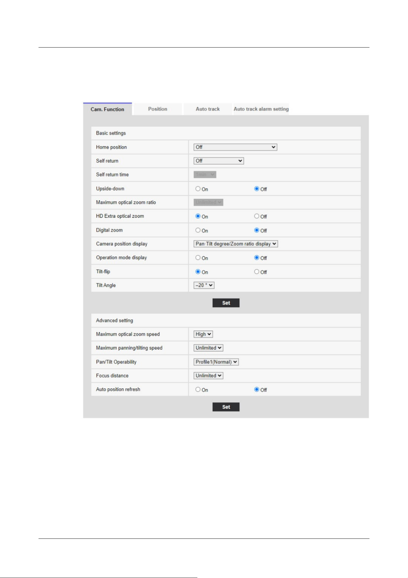
11.1.1 [Cam. Function] for setting the operation of Rapid PTZ Cameras, Multi-
directional + PTZ (PTZ part)
[Home position]
You can set the preset position as the home position.
When the home position is set, [H] is displayed next to the preset position number.
→11.2.1 Set the preset position (preset position setting screen)
11 Set PTZ
11.1 [Cam. Function] for setting the operation of cameras
369

[Note:]
If you want to move to the home position when the power is turned on, set
[HomePosition] to [Self return].
[Note:]
If you want to perform the above operations when turning on the power, it is
convenient to use the self-turn function.
The Self-turn function works even when the Setup menu is displayed.
・[Patrol] can be set only when patrols are set.
→11.2.4 Set patrol (Patrol function setting screen)
・[Preset sequence] can be set only when the preset sequence is set.
→11.2.2 Set the preset sequence setting (preset sequence setting screen)
[Self return]
When the time set by [Self return time] has elapsed after manual operation, the camera can
automatically return to one of the following modes of operation.
[Off]:Do not perform self-return.
[Home position]:After the set time has elapsed, the watch returns to the home position.
[Auto Pan]:When the set time elapses, the auto pan operation starts.
[Preset Sequence 1]:When the set time elapses, Sequence 1 operation starts.
[Preset Sequence 2]:Sequence 2 operation starts when the set time elapses.
[Preset Sequence 3]:Sequence 3 operation starts when the set time elapses.
[Patrol]:When the set time elapses, the patrol operation starts.
[Self return time]
After the manual operation is completed, select the time from the following to return to the
operation set by [Self return].
[10s]/ [20s]/ [30s]/ [1min]/ [2min]/ [3min]/ [5min]/ [10min]/ [20min]/ [30min]/ [60min]
[Maximum optical zoom ratio]
Select the maximum zoom ratio for the optical zoom from the following. Refer to the catalog
specifications for the installed optical zoom ratio.
・Optical zoom: 21x model x1/x2/x3/x4/x5/x6/x7/x8/x9/x10/x11/x12/x13/x14/x15/x16/x17/
x19/x20/unlimited
・Optical zoom: 30x model x1/x2/x3/x4/x5/x6/x7/x8/x9/x10/x11/x12/x13/x14/x15/x16/x17/
x18/x19/x20/x21/x22/x24/x26/x27/x28/x29/unlimited
・Optical zoom: 32x model x1/x2/x3/x4/x5/x6/x7/x8/x9/x10/x11/x12/x13/x14/x15/x16/x17/
11 Set PTZ
11.1 [Cam. Function] for setting the operation of cameras
370

x18/x19/x20/x21/x22/x23/x24/x26/x27/x28/x30/x31/unlimited
・Optical zoom: 40x model x1/x2/x3/x4/x5/x6/x8/x8/x9/x10/x11/x12/x13/x14/x15/x16/x17/
x18/x19/x20/x21/x22/x23/x24/x26/x27/x28/x29/x30/x31/x32/x33/x34/x36/x37/x38/x39/
unlimited
[HD Extra optical zoom]
Select the setting of HD EX optical zoom from the following.
[On]:When the optical zoom range is exceeded, the HD EX optical zoom is performed.
[Off]:HD EX optical zoom is not performed. It is within the optical zoom range.
What is HD EX optical zoom?
Among the effective pixels of the MOS sensor, approximately 920,000 pixels (equivalent to 1280 x
720 resolution) are cut off from the center and shot. Therefore, using a resolution of less than
1280 x 720 makes it possible to shoot with a higher telephoto effect.
About HD EX optical zoom
・Optical zoom: For a 21x model, x1 to x21 optics is performed, and for more than x31 HD EX
optical zoom is performed.
・Optical zoom: For a 30x model, x1 to x30 optics is performed, and for more than x90 HD EX
optical zoom is performed.
・Optical zoom: For a 32x model, x1 to x32 optics is performed, and for more than x48 HD EX
optical zoom is performed.
・Optical zoom: For a 40x model, x1 to x40 optics is performed, and for more than x60 HD EX
optical zoom is performed.
[Digital zoom]
Select the digital zoom setting from the following.
[On]:When the optical zoom and HD EX optical zoom are exceeded, digital zoom is performed.
[Off]:Digital zoom is not performed.
About Digital zoom
・Optical zoom: For a 21x model, x1 to x21 optical zoom, x31 HD EX optical zoom, and more (up
to x336) digital zoom are performed.
・Optical zoom: For a 30x model, x1 to x30 optical zoom, x90 HD EX optical zoom, and more (up
to x480) digital zoom are performed.
・Optical zoom: For a 32x model, x1 to x32 optical zoom, x48 HD EX optical zoom, and more (up
to x512) digital zoom are performed.
・Optical zoom: For a 40x model, x1 to x40 optical zoom, x60 HD EX optical zoom, and more (up
to x640) digital zoom are performed.
11 Set PTZ
11.1 [Cam. Function] for setting the operation of cameras
371

[Note:]
When [On] is set to Digital Zoom, it stops once just before the Digital Zoom
magnification changes during the zoom operation.
The preset position cannot be set with the digital zoom factor.
If [HD Extra optical zoom] is [Off], [Digital zoom] cannot be set to [On].
[Note:]
When set to • [Pan·Tilt degree/Zoom ratio display], the pan tilt angles/
magnifications are displayed in the [Camera title position] set on the Basic Page
[Basic] tab.
→11.2.6 Setting of pan/tilt range (pan/tilt range setting screen)
When set to • [Direction display], the orientation is displayed in the [Camera title
position] you set on the [Basic] tab of the basic page.
→11.2.5 Setting for direction/direction setting (direction/direction setting screen)
To select • [Direction display], set the reference northern direction with the
[Direction/Angle setting] [North point setting].
→11.2.5 Setting for direction/direction setting (direction/direction setting screen)
Operation mode Display
During startup INITIAL
During auto pan AUTO PAN
Automatic tracking (in progress) AUTO TRACKING
During patrol PATROL
During the preset sequence PRESET SEQ
[Camera position display]
Select the information displayed in the image during manual operation from the following.
[Off]:The information is not displayed in the image.
[Pan tilt angle/magnification display]:Displays pan angle/tilt angle/magnification.
[Directional view]:Displays the direction.
[Operation mode display]
Displays the operation mode when the camera is running automatically.
[On]:Displays the operating mode.
[Off]:The operation mode is not displayed.
[Tilt-flip]
Select the tilt-flip setting from the following.
11 Set PTZ
11.1 [Cam. Function] for setting the operation of cameras
372

[Note:]
• Even if the tilt-flip function is activated on the TELE side, some parts are not
visible.
In the main area of the Live image pages, clicking the desired position for the
center of the field angle moves the orientation of the camera to the center of the
clicked position. In this case, the product continues to operate without stopping at
the tilt end point.
• During flip movement, the image being moved is displayed.
[Note:]
The screen may be partially darkened if it is directed above-20 degrees.
[On]:When the tilt end point (directly below) is reached during manual operation, the pan can be
automatically rotated at a high speed to continue operation without stopping at the tilt end point.
[Off]:The tilt-flip function does not work.
[Tilt Angle]
Select the angle limit of tilt operation from the following. (Horizontal = 0°)
10°/ 5°/ 3°/ 0°/ −3°/ −5°/ −10°/ −15°/ −20°/ −25°/ −30°
[Maximum optical zoom speed]
Select the maximum speed of the optical zoom.
[High]/[Mid]/[Low]
[Maximum panning/tilting speed]
Select the maximum speed for pan tilt operation.
[1°/s], [2°/s], [5°/s], [10°/s], [25°/s], [50°/s], [90°/s], [135°/s], [150°/s],
[300°/s], [400°/s], [500°/s], [600°/s], [Unlimited]
[Focus distance]
If you have a object over the window or a different object over a short distance, it may be difficult
to focus on the object you want to view. If the camera is not focused properly, you can limit the
shortest shooting distance.
[Unlimited]/[1.5m]/ [3m]/ [5m]/ [10m]
[Auto position refresh]
Turning on the Auto position refresh, when the panning (turning) angle deviates by a certain
amount, so that it will automatically shift to the positive position.
[On]:Perform position refresh automatically.
11 Set PTZ
11.1 [Cam. Function] for setting the operation of cameras
373
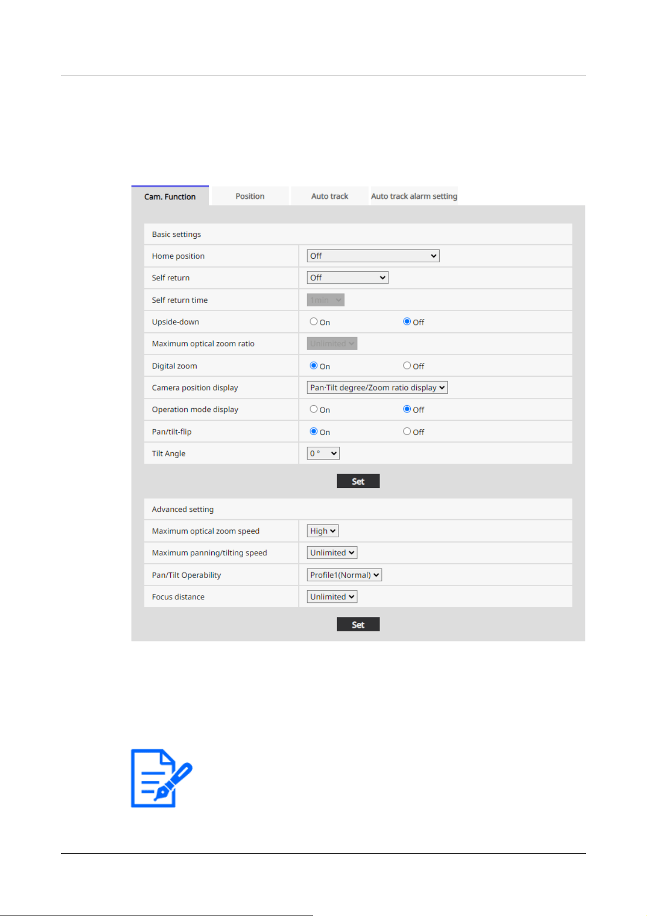
[Note:]
If you want to move to the home position when the power is turned on, set
[HomePosition] to [Self return].
[Off]:Not perform position refresh automatically.
11.1.2 [Cam. Function] for setting the operation of Indoor PTZ cameras
[Home position]
You can set the preset position as the home position.
When the home position is set, [H] is displayed next to the preset position number.
→11.2.1 Set the preset position (preset position setting screen)
11 Set PTZ
11.1 [Cam. Function] for setting the operation of cameras
374

[Note:]
If you want to perform the above operations when turning on the power, it is
convenient to use the self-turn function.
The Self-turn function works even when the Setup menu is displayed.
・[Patrol] can be set only when patrols are set.
→11.2.4 Set patrol (Patrol function setting screen)
・[Preset sequence] can be set only when the preset sequence is set.
→11.2.2 Set the preset sequence setting (preset sequence setting screen)
[Self return]
When the time set by [Self return time] has elapsed after manual operation, the camera can
automatically return to one of the following modes of operation.
[Off]:Do not perform self-return.
[Home position]:After the set time has elapsed, the watch returns to the home position.
[Auto Pan]:When the set time elapses, the auto pan operation starts.
[Preset Sequence 1]:When the set time elapses, Sequence 1 operation starts.
[Preset Sequence 2]:Sequence 2 operation starts when the set time elapses.
[Preset Sequence 3]:Sequence 3 operation starts when the set time elapses.
[Patrol]:When the set time elapses, the patrol operation starts.
[Self return time]
After the manual operation is completed, select the time from the following to return to the
operation set by [Self return].
[10s]/ [20s]/ [30s]/ [1min]/ [2min]/ [3min]/ [5min]/ [10min]/ [20min]/ [30min]/ [60min]
[Upside-down]
Use [On] or [Off] to set whether to flip the images up or down.
[On]:The image is inverted upside down.
[Off]:The image is not flipped up or down.
[Maximum optical zoom ratio]
Select the maximum zoom ratio for the optical zoom from the following. Refer to the catalog
specifications for the installed optical zoom ratio.
・Optical zoom: 30x model x1/x2/x3/x4/x5/x6/x7/x8/x9/x10/x11/x12/x13/x14/x15/x16/x17/
x18/x19/x20/x21/x22/x24/x26/x27/x28/x29/unlimited
[Digital zoom]
Select the digital zoom setting from the following.
[On]:When the optical zoom is exceeded, digital zoom is performed.
[Off]:Digital zoom is not performed.
11 Set PTZ
11.1 [Cam. Function] for setting the operation of cameras
375

[Note:]
・When [On] is set to Digital Zoom, it stops once just before the Digital Zoom
magnification changes during the zoom operation.
・The preset position cannot be set with the digital zoom factor.
・Refer to the catalog specifications for the maximum digital zoom ratio.
[Note:]
When set to • [Pan·Tilt degree/Zoom ratio display], the pan tilt angles/
magnifications are displayed in the [Camera title position] set on the Basic Page
[Basic] tab.
→11.2.6 Setting of pan/tilt range (pan/tilt range setting screen)
When set to • [Direction display], the orientation is displayed in the [Camera title
position] you set on the [Basic] tab of the basic page.
→11.2.5 Setting for direction/direction setting (direction/direction setting screen)
To select • [Direction display], set the reference northern direction with the
[Direction/Angle setting] [North point setting].
→11.2.5 Setting for direction/direction setting (direction/direction setting screen)
Operation mode Display
During startup INITIAL
During auto pan AUTO PAN
Automatic tracking (in progress) AUTO TRACKING
During patrol PATROL
About Digital zoom
・Optical zoom: For a 30x model, x1 to x30 optical zoom, x90 HD EX optical zoom, and more (up
to x480) digital zoom are performed.
[Camera position display]
Select the information displayed in the image during manual operation from the following.
[Off]:The information is not displayed in the image.
[Pan tilt angle/magnification display]:Displays pan angle/tilt angle/magnification.
[Directional view]:Displays the direction.
[Operation mode display]
Displays the operation mode when the camera is running automatically.
[On]:Displays the operating mode.
[Off]:The operation mode is not displayed.
11 Set PTZ
11.1 [Cam. Function] for setting the operation of cameras
376

During the preset sequence PRESET SEQ
[Note:]
On the TELE side, some parts are not visible even when the pan/tilt flip function is
activated.
In the main area of the live image page, clicking the desired position for the center
of the field angle moves the camera's orientation to the center of the clicked
position. In this case, the operation continues without stopping at the pan tilt end
point.
・During flip movement, the image being moved is displayed.
[Note:]
The screen may be partially darkened if it is directed above-20 degrees.
[Pan/tilt-flip]
Select the pan/tilt flip setting from the following.
[On]:When the pan end point and the tilt end point (directly below) are reached during manual
operation, the pan can be automatically rotated at high speed to continue operation without
stopping at the pan end point and the tilt end point.
[Off]:The pan/tilt flip function does not work.
[Tilt Angle]
Select the angle limit of tilt operation from the following. (Horizontal = 0°)
10°/ 5°/ 3°/ 0°/ −3°/ −5°/ −10°/ −15°/ −20°/ −25°
[Maximum optical zoom speed]
Select the maximum speed of the optical zoom.
[High]/[Mid]/[Low]
[Maximum panning/tilting speed]
Select the maximum speed for pan tilt operation.
[1°/s], [2°/s], [5°/s], [10°/s], [25°/s], [50°/s], [90°/s], [135°/s], [150°/s],
[300°/s], [Unlimited]
[Focus distance]
If you have a object over the window or a different object over a short distance, it may be difficult
to focus on the object you want to view. If the camera is not focused properly, you can limit the
shortest shooting distance.
11 Set PTZ
11.1 [Cam. Function] for setting the operation of cameras
377
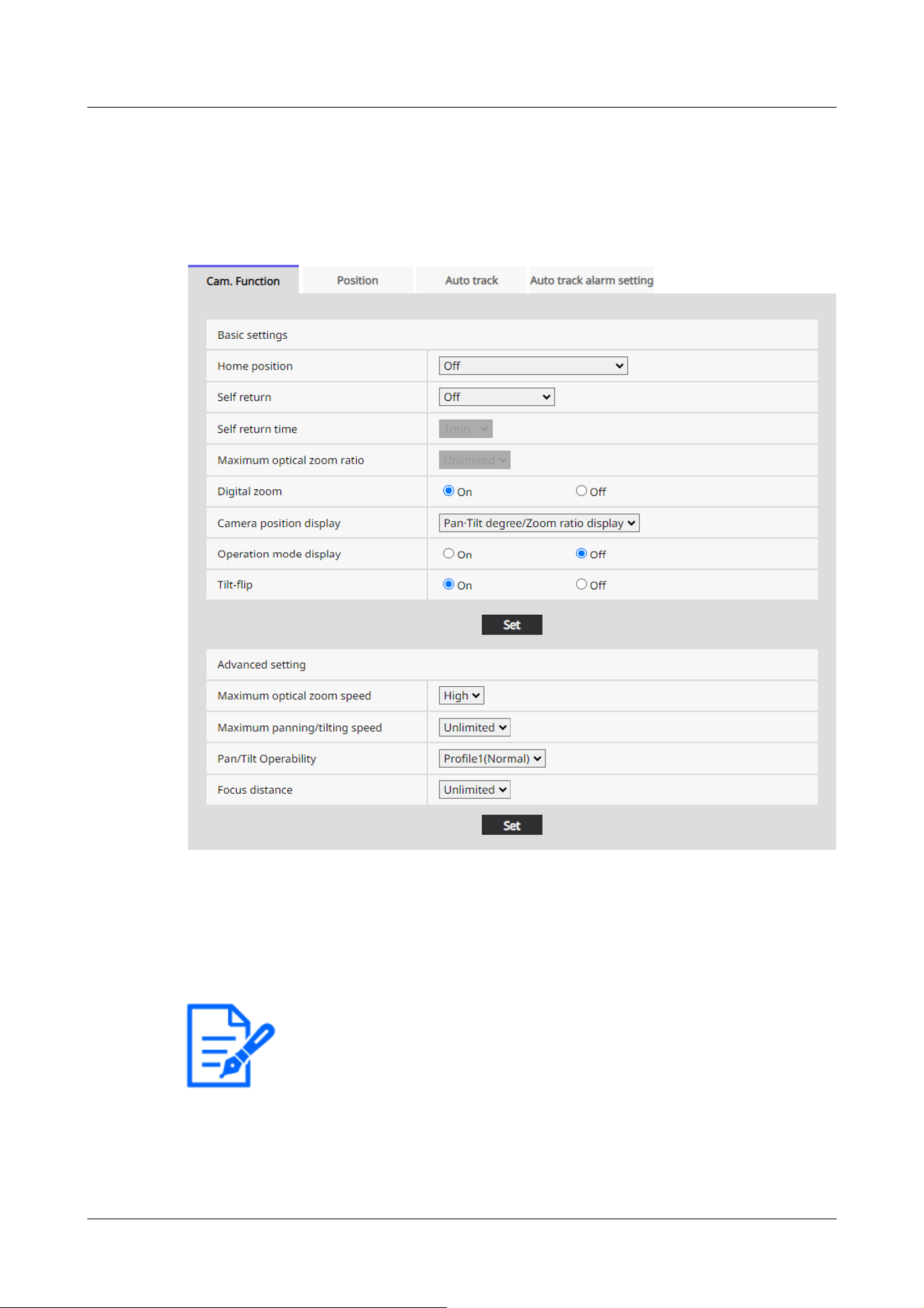
[Note:]
If you want to move to the home position when the power is turned on, set
[HomePosition] to [Self return].
[Unlimited]/ [3m]/ [5m]/ [10m]
11.1.3 [Cam. Function] for setting the operation of Aero PTZ cameras
[Home position]
You can set the preset position as the home position.
When the home position is set, [H] is displayed next to the preset position number.
→11.2.1 Set the preset position (preset position setting screen)
[Self return]
When the time set by [Self return time] has elapsed after manual operation, the camera can
11 Set PTZ
11.1 [Cam. Function] for setting the operation of cameras
378

[Note:]
If you want to perform the above operations when turning on the power, it is
convenient to use the self-turn function.
The Self-turn function works even when the Setup menu is displayed.
・[Patrol] can be set only when patrols are set.
→11.2.4 Set patrol (Patrol function setting screen)
・[Preset sequence] can be set only when the preset sequence is set.
→11.2.2 Set the preset sequence setting (preset sequence setting screen)
automatically return to one of the following modes of operation.
[Off]:Do not perform self-return.
[Home position]:After the set time has elapsed, the watch returns to the home position.
[Auto Pan]:When the set time elapses, the auto pan operation starts.
[Preset Sequence 1]:When the set time elapses, Sequence 1 operation starts.
[Preset Sequence 2]:Sequence 2 operation starts when the set time elapses.
[Preset Sequence 3]:Sequence 3 operation starts when the set time elapses.
[Patrol]:When the set time elapses, the patrol operation starts.
[Self return time]
After the manual operation is completed, select the time from the following to return to the
operation set by [Self return].
[10s]/ [20s]/ [30s]/ [1min]/ [2min]/ [3min]/ [5min]/ [10min]/ [20min]/ [30min]/ [60min]
[Maximum optical zoom ratio]
Select the maximum zoom ratio for the optical zoom from the following. Refer to the catalog
specifications for the installed optical zoom ratio.
・Optical zoom: 30x model
x1/x2/x3/x4/x5/x6/x7/x8/x9/x10/x11/x12/x13/x14/x15/x16/x17/x18/x19/x20/x21/x22/
x24/x26/x27/x28/x29/unlimited
・Optical zoom: 40x model
x1/x2/x3/x4/x5/x6/x8/x8/x9/x10/x11/x12/x13/x14/x15/x16/x17/x18/x19/x20/x21/x22/
x23/x24/x26/x27/x28/x29/x30/x31/x32/x33/x34/x36/x37/x38/x39/unlimited
[Digital zoom]
Select the digital zoom setting from the following.
[On]:When the optical zoom is exceeded, digital zoom is performed.
[Off]:Digital zoom is not performed.
About Digital zoom
・Optical zoom: For a 30x model, x1 to x30 optical zoom, and more (up to x480) digital zoom are
11 Set PTZ
11.1 [Cam. Function] for setting the operation of cameras
379

[Note:]
When [On] is set to Digital Zoom, it stops once just before the Digital Zoom
magnification changes during the zoom operation.
[Note:]
When set to • [Pan·Tilt degree/Zoom ratio display], the pan tilt angles/
magnifications are displayed in the [Camera title position] set on the Basic Page
[Basic] tab.
→11.2.6 Setting of pan/tilt range (pan/tilt range setting screen)
When set to • [Direction display], the orientation is displayed in the [Camera title
position] you set on the [Basic] tab of the basic page.
→11.2.5 Setting for direction/direction setting (direction/direction setting screen)
To select • [Direction display], set the reference northern direction with the
[Direction/Angle setting] [North point setting].
→11.2.5 Setting for direction/direction setting (direction/direction setting screen)
Operation mode Display
During startup INITIAL
During auto pan AUTO PAN
Automatic tracking (in progress) AUTO TRACKING
During patrol PATROL
During the preset sequence PRESET SEQ
performed.
・Optical zoom: For a 40x model, x1 to x40 optical zoom, and more (up to x640) digital zoom are
performed.
[Camera position display]
Select the information displayed in the image during manual operation from the following.
[Off]:The information is not displayed in the image.
[Pan tilt angle/magnification display]:Displays pan angle/tilt angle/magnification.
[Directional view]:Displays the direction.
[Operation mode display]
Displays the operation mode when the camera is running automatically.
[On]:Displays the operating mode.
[Off]:The operation mode is not displayed.
11 Set PTZ
11.1 [Cam. Function] for setting the operation of cameras
380

[Note:]
• Even if the tilt-flip function is activated on the TELE side, some parts are not
visible.
In the main area of the Live image pages, clicking the desired position for the
center of the field angle moves the orientation of the camera to the center of the
clicked position. In this case, the product continues to operate without stopping at
the tilt end point.
• During flip movement, the image being moved is displayed.
[Tilt-flip]
Select the tilt-flip setting from the following.
[On]:When the tilt end point (directly below) is reached during manual operation, the pan can be
automatically rotated at a high speed to continue operation without stopping at the tilt end point.
[Off]:The tilt-flip function does not work.
[Maximum optical zoom speed]
Select the maximum speed of the optical zoom.
[High]/[Mid]/[Low]
[Maximum panning/tilting speed]
Select the maximum speed for pan tilt operation.
[1°/s], [2°/s], [5°/s], [10°/s], [25°/s], [50°/s], [90°/s], [135°/s], [150°/s],
[Unlimited]
[Focus distance]
If you have a object over the window or a different object over a short distance, it may be difficult
to focus on the object you want to view. If the camera is not focused properly, you can limit the
shortest shooting distance.
[Unlimited]/[1.5m]/ [3m]/ [5m]/ [10m]
11.2 [Position] for setting positions
Click on the [Position] tab of the PTZ page. Refer to the following how to display and operate the
Advanced menu.
→5.1 How to display
→5.2 How to operate
To Advanced Settings for each item>>Clicking this button displays the advanced settings window
11 Set PTZ
11.2 [Position] for setting positions
381
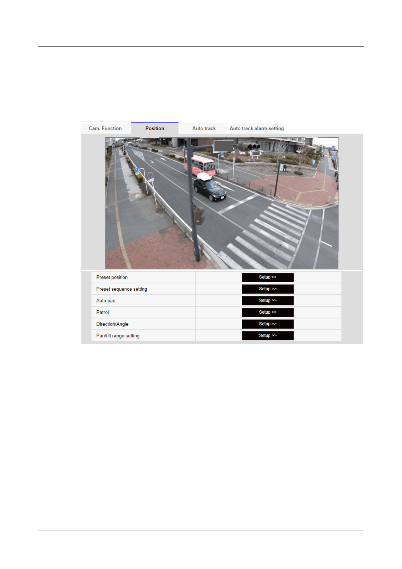
in a separate window and allows you to set the settings while viewing the images displayed on the
[Position] tab.
Here, you can set the image quality adjustment, preset position, preset sequence setting, auto
pan, patrol, direction/direction setting, and pan/tilt range setting.
[Preset position]
To Advanced Settings>>When the button is clicked, the preset position setting window is
displayed in a separate window.
→11.2.1 Set the preset position (preset position setting screen)
[Preset sequence setting]
To Advanced Settings>>When the [button] is clicked, the preset sequence settings window is
displayed in a separate window.
→11.2.2 Set the preset sequence setting (preset sequence setting screen)
[Auto pan]
To Advanced Settings>>Click the [Auto Pan] button to display the auto pan setting window in a
11 Set PTZ
11.2 [Position] for setting positions
382

separate window.
→11.2.3 Set auto pan (Auto pan setting screen)
[Patrol]
To Advanced Settings>>When the [Patrol] button is clicked, the setting window for the patrol is
displayed in another window.
→11.2.4 Set patrol (Patrol function setting screen)
[Direction/Angle]
To Advanced Settings>>When the button is clicked, the setting window for direction/direction
setting is displayed in a separate window.
→11.2.5 Setting for direction/direction setting (direction/direction setting screen)
[Pan/tilt range setting]
To Advanced Settings>>Click the [Button] button to open a window for specifying the pan/tilt
range.
→11.2.6 Setting of pan/tilt range (pan/tilt range setting screen)
11.2.1 Set the preset position (preset position setting screen)
In the [Position] tab of the PTZ-page to the Advanced Settings tab of [Preset position]>>Click the
[Button].
→11.2 [Position] for setting positions
Here, you can register, change, or delete the preset position.
If you adjust the focus, brightness, zoom, etc., the images on the [Position] tabs will be reflected
at the same time.
11 Set PTZ
11.2 [Position] for setting positions
383
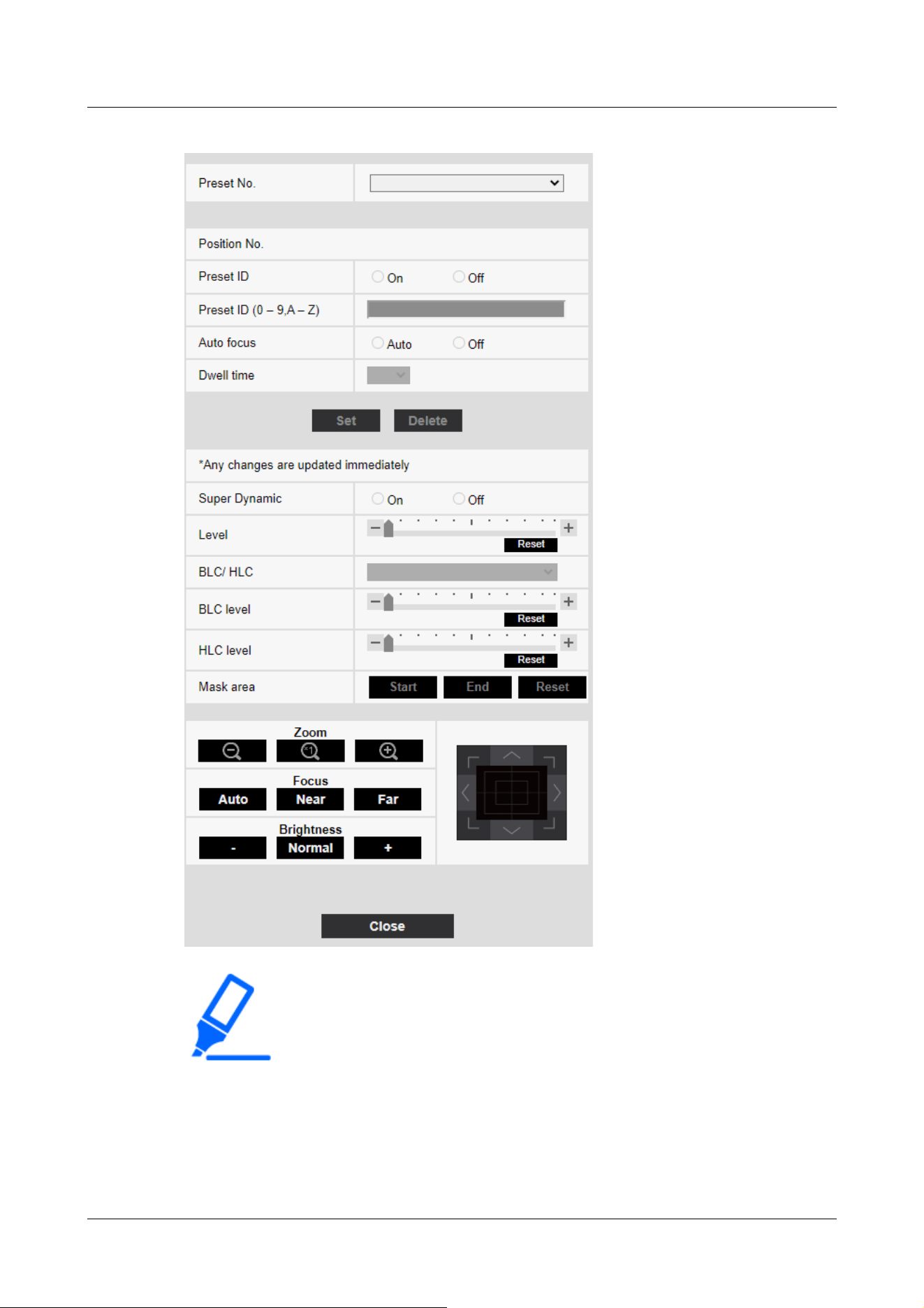
[Important]
・Do not change other settings during preset position setting. The image may not
be displayed correctly.
・[Rapid PTZ][MULTI_PTZ] The preset position cannot be set with the magnification
of the digital zoom.
・[Indoor PTZ][Aero PTZ] You can set a preset position up to half the maximum
camera magnification.
11 Set PTZ
11.2 [Position] for setting positions
384

・Up to 256 preset positions can be set.
[Note:]
・Depending on the operating environment (+5 °C or less as a guideline), the
speed of the preset movement may be slightly slower.
[Important]
・If you have configured [Preset ID (0 – 9,A – Z)] and [Preset ID], be
sure to press [Register].
[Note:]
・When set to [On], the position name is displayed where you set the position in
[Camera title position] on the [Basic] tab.
[Note:]
・The position name entered is displayed next to the preset position number in the
pull-down. If [Preset ID] is set to [On], it can also be displayed on the images.
Preset position setting
[Preset ID]
Use [On] and [Off] to set whether the position name is displayed. You can set for each preset
position.
[On]:Displays the position name.
[Off]:The position name is not displayed.
[Preset ID (0 – 9,A – Z)]
Enter the name to be displayed on the image. You can set for each preset position.
Number of characters that can be entered:0 to 40 characters
Input Characters:0-9 (single-byte), A-Z (single-byte, uppercase, lowercase), double-byte,
single-byte symbol ! " # $ % & ' ( ) * + , ‑ . / : ; = ?
[Auto focus]
Use [Auto] and [Off] to set whether auto focus is performed after the preset is moved. You can set
for each preset position.
[Auto]:Auto focus is performed after the preset is moved.
[Off]:Auto focus is not performed after moving the preset.
11 Set PTZ
11.2 [Position] for setting positions
385

[Note:]
・When presetting a subject whose depth does not change, a subject whose
contrast is low, or a subject with high brightness such as a spotlight, etc., set
[Off] and register the preset position after setting the focus.
[Note:]
・Depending on the stop time setting, the watch may move to the next preset
position during auto focus operation.
・If the preset sequence function is used for a long time, the drive parts may be
consumed and the replacement cycle of consumables may be faster. For
consumables, refer to the Web Guide.
[Note:]
・Set [Super Dynamic] to [Off] when the following phenomena are observed
depending on the lighting condition.
-when flickering or color changes occur
-when noise is generated in the bright area of the screen
・If [Light control mode] is set to [Fix shutter], [Super Dynamic] cannot be set to
[On].
・When [Stabilizer] is set to [On], the superdynamic setting is [Off].
・[Rapid PTZ-8M(4K)][Rapid PTZ-6M][Aero PTZ-8M(4K)] If you switch the [Super
Dynamic] from [On] to [Off] or from [Off] to [On], the images may be distorted.
[Dwell time]
During the preset sequence operation, select the time to reflect the image of each preset position
(the time when the camera stops rotating) from the following.
[5s]/ [10s]/ [15s]/ [20s]/ [25s]/ [30s]
[Super Dynamic]
You can set [On] or [Off] to activate the super dynamic function. You can set for each preset
position.
This cannot be set when [Image capture mode] is [16:9 mode(60fps mode)] or [16:9 mode(50fps
mode)].
See [What is Super Dynamic] for details on super dynamic.
[On]:The Super Dynamic function is activated.
[Off]:Stops the superdynamic function.
[Level]
11 Set PTZ
11.2 [Position] for setting positions
386

[Note:]
・Depending on [Image adjust]'s [Super Dynamic] and [Level] settings, [Preset
position]'s [Super Dynamic] and [Level] operations may change.
→10.4.1 To adjust the image quality (image quality adjustment screen)
Adjust the superdynamic level.
When the slider bar is moved in the [+] direction, you can shoot a subject with a large difference in
light and darkness without flipping white or shading black.
Move the slider bar in the [-] direction to take a full picture of the middle brightness.
Press [Reset] to return to the default settings.
[BLC/ HLC]
Select from the following. This setting is not available if [Super Dynamic] is set to [On] or
[Intelligent Auto] is set to [On].
[Back Light Correction (BLC)]:Enables the backlight correction function.
[Intensity correction]:Enables the high light correction function. Illumination compensation
suppresses bright lighting of subjects such as car headlights during nighttime.
[Off]:Stops the backlight compensation function and the intense light correction function.
[BLC level]
Adjust the backlight correction level.
Moving the slider bar in the [+] direction improves the backlight correction effect.
Moving the slider bar in the [-] direction reduces the effect of backlight correction.
Press [Reset] to return to the default settings.
[HLC level]
Adjust the intensity correction level.
Moving the slider bar in the [+] direction improves the effect of intense light correction.
Moving the slider bar in the [-] direction reduces the effect of intense light correction.
Press [Reset] to return to the default settings.
[Mask area]
When the mask area is set, the set area can be masked and the light intensity can be adjusted. If
[Super Dynamic] is set to [On], it cannot be set.
For details on how to set the mask area, refer to the following.
→10.4.2 Set the mask area
11 Set PTZ
11.2 [Position] for setting positions
387

[Note:]
・When registering the preset position, the camera may move slightly.
・If [Image adjust] [Scene file] is set to other than [Scene file is not applied], [Super
Dynamic], [BLC/ HLC], and [Mask area] cannot be set.
[Zoom], [Focus], Control Pad/Button, [Brightness] Button
Please refer to the following instructions for operation.
→10.4.6 Setting the privacy zone (Privacy zone setting screen)
[Set] buttons
Register the preset position.
[Delete] buttons
Deletes the preset position selected by the position number.
[Close] buttons
Click this button to close the preset position setting window.
Register the preset position
1 Select the position number.
[Position No.] shows the selected position number.
→11.2.1 Set the preset position (preset position setting screen)
If it is already registered, the camera moves to the preset position selected.
2 Move the camera direction in the direction you want to register.
3 If you want the position name to appear on the live image page, set [Preset ID] to [On] and
enter the position name.
4 Set Auto Focus or Stop Time.
5 Press [Register].
6 To set image quality for each position, set each item such as Super Dynamic. [Super
Dynamic], [BLC/ HLC], and [Mask area] are reflected immediately.
11.2.2 Set the preset sequence setting (preset sequence setting screen)
To [Preset sequence setting] Advanced Settings on the [Position] tabs of PTZ pages>>Click the
[Button].
→11.2 [Position] for setting positions
Here, you can register, change, or delete the preset sequence.
11 Set PTZ
11.2 [Position] for setting positions
388
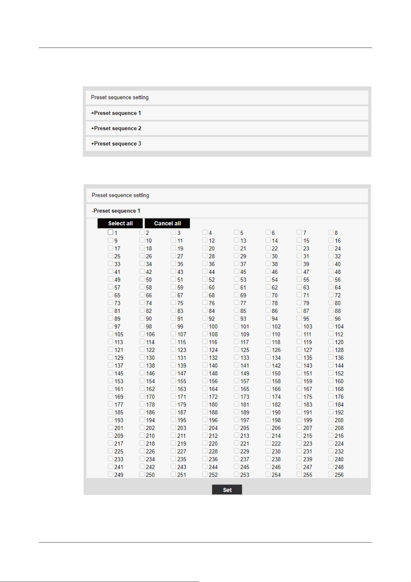
Up to three preset sequences can be set.
Preset sequence setting
Preset Sequence 1, Preset Sequence 2, Preset Sequence 3
11 Set PTZ
11.2 [Position] for setting positions
389

[Note:]
・When the preset sequence is activated, the registered preset positions are
moved from a younger number to a higher order.
・After moving to the trailing preset position, the system returns to the youngest
number and moves the preset position back in sequence.
[Note:]
・The items that can be set differ depending on the function of the model.
・Refer to the catalog specifications for the functions installed in each model.
・If the auto pan function is used for a long time, the drive parts may be consumed
and the replacement cycle of consumables may be faster. For consumables, refer
to the Web Guide.
The preset sequence can be set.
[Select all] button:Select all preset positions.
[Cancel all] button:You can release all selections.
1~256:Enables/disables the corresponding preset position.
[Set] button:Save the settings of the created preset sequence.
11.2.3 Set auto pan (Auto pan setting screen)
In the [Position] tab of the PTZ-page to the Advanced Settings tab of [Auto pan]>>Click the
[Button].
→11.2 [Position] for setting positions
Here, you can set auto pan.
Rapid PTZ Cameras, Multi-directional + PTZ(PTZ part)
11 Set PTZ
11.2 [Position] for setting positions
390
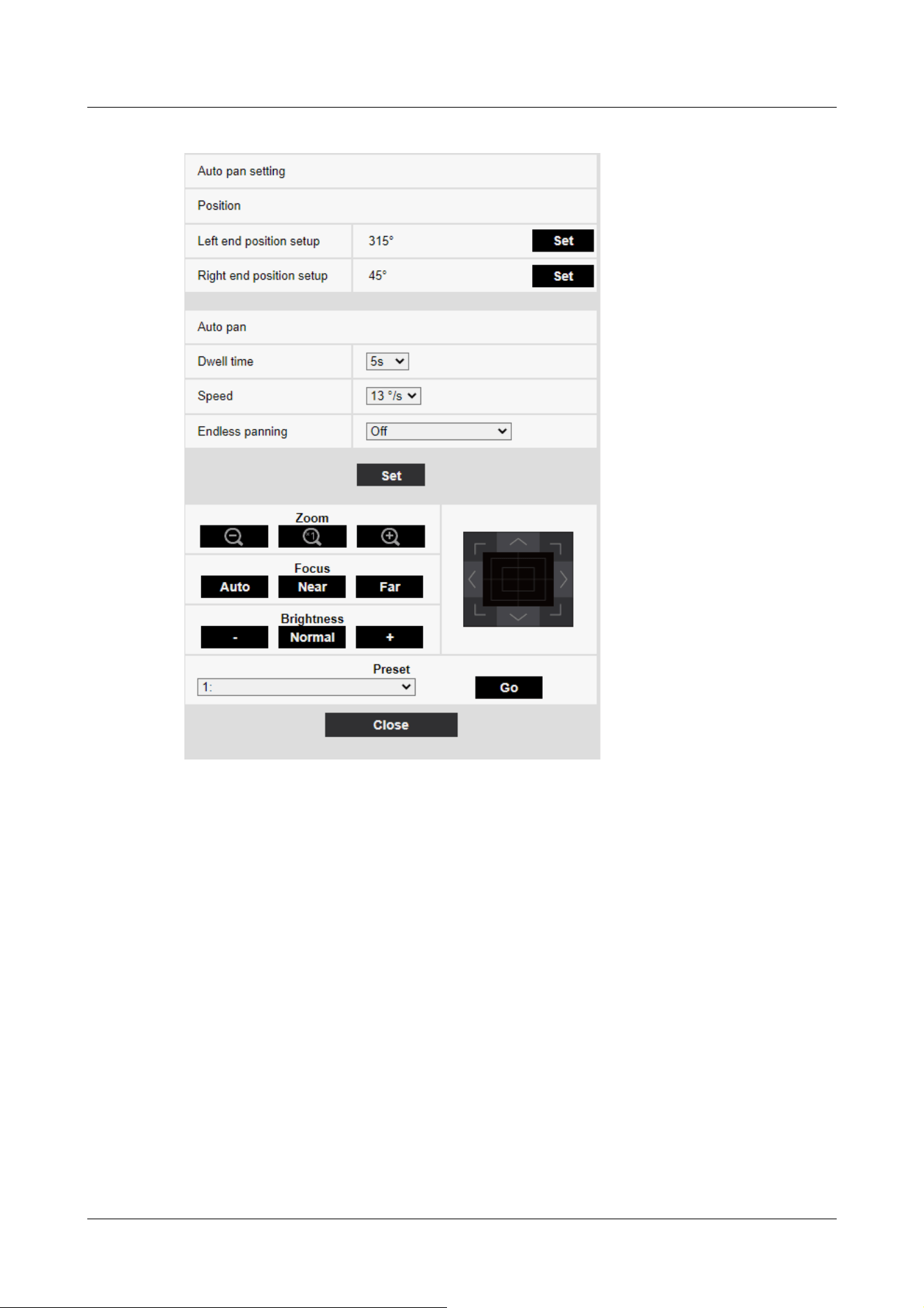
Indoor PTZ cameras
11 Set PTZ
11.2 [Position] for setting positions
391
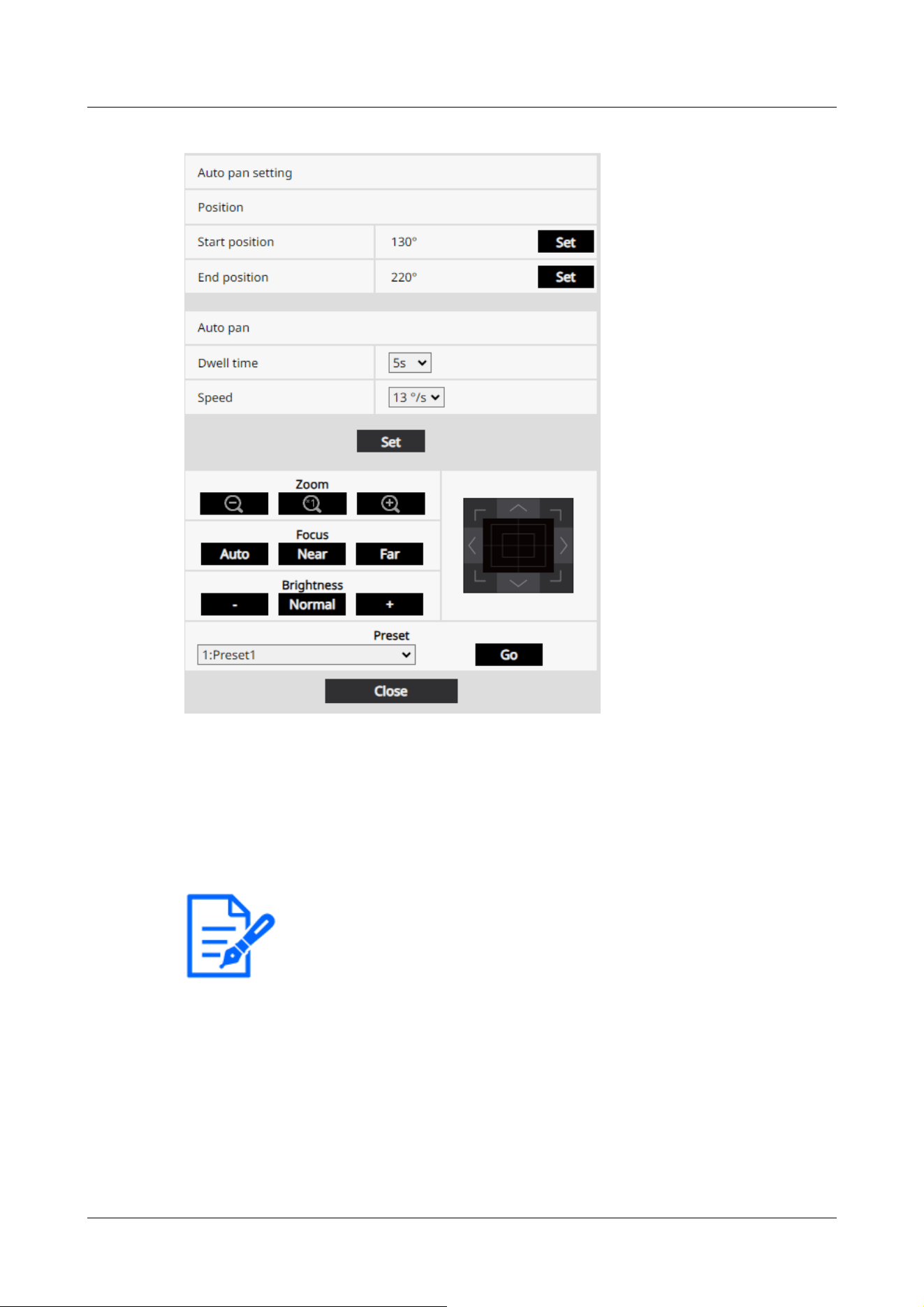
[Note:]
・The pan, tilt, and zoom operations are also available on the images in the
[Position] tabs.
Setting the end point
[Left end position setup]
Use the [Zoom], [Focus] and Control Pad/Buttons to move the camera to the desired position at
the left end of the auto pan, and then press the [Set] button. Zoom and focus are set at the same
time.
[Right end position setup]
Use the Control Pad/Button to move the camera to the desired position for the right end of the
auto pan, and then press the [Set] button.
[Start position]
Use the [Zoom], [Focus] and Control Pad/Buttons to move the camera to the desired position at
the left end of the auto pan, and then press the [Set] button. Zoom and focus are set at the same
11 Set PTZ
11.2 [Position] for setting positions
392

[Note:]
・The pan, tilt, and zoom operations are also available on the images in the
[Position] tabs.
[Important]
・If you set [Auto pan], be sure to press [Set].
[Note:]
・Even when the magnification of the digital zoom is set, the turn of the pan
operation is performed at a position less than 34 times.
time.
[End position]
Use the Control Pad/Button to move the camera to the desired position for the right end of the
auto pan, and then press the [Set] button.
Auto pan operation
[Dwell time]
Select the stop time at the start and end positions from the following.
[0s]/ [1s]/ [2s]/ [3s]/ [4s]/ [5s]/ [10s]/ [15s]/ [20s]/ [25s]/ [30s]
[Speed]
Select the pivot speed of the pan operation from the following.
[1°/s]、 [2°/s]、 [3°/s]、 [4°/s]、 [5°/s]、 [7°/s]、 [10°/s]、 [13°/s]、 [18°/s]、
[24°/s]
[Zoom], [Focus], Control Pad/Button, [Brightness], and Move presets buttons
Please refer to the following instructions for operation.
→2.3.2 About live image pages
[Close] buttons
Click this button to close the auto pan setting screen.
11 Set PTZ
11.2 [Position] for setting positions
393
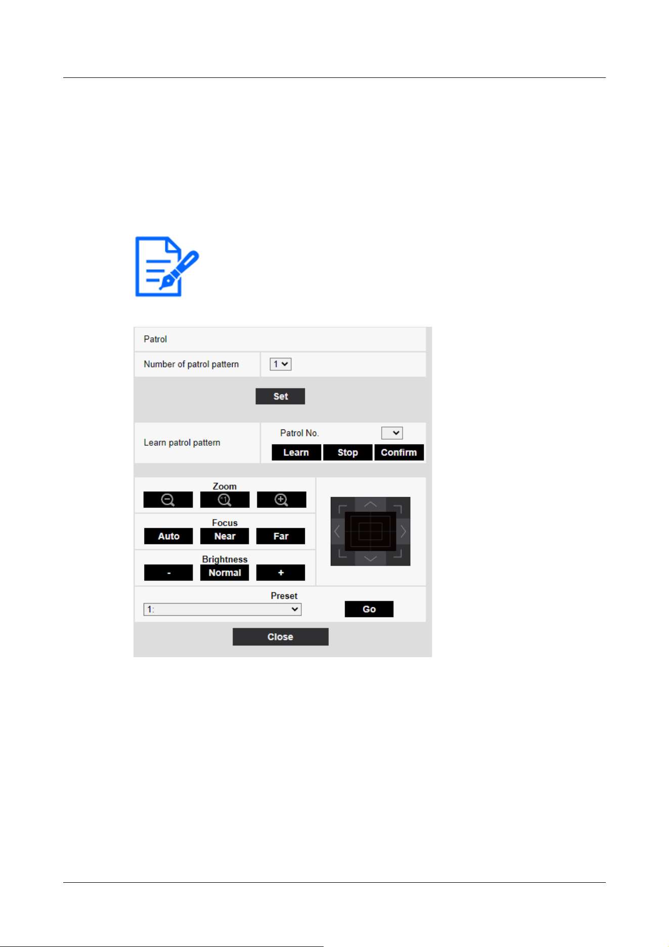
[Note:]
・If the patrol function is used for a long time, the drive parts may be consumed and
the replacement cycle of consumables may be faster. For consumables, refer to
the Web Guide.
11.2.4 Set patrol (Patrol function setting screen)
In the [Position] tab of the PTZ-page to the Advanced Settings tab of [Patrol]>>Click the
[Button]. Here, information about patrols is set.
→11.2 [Position] for setting positions
The patrol function stores the pan/tilt/zoom/focus and reproduces the stored operation.
Patrol setting
[Number of patrol pattern]
Select the number of memories in the patrol. The amount of time that can be stored varies
depending on the number of memories.
1:The operation for 2 minutes is stored in Patrol 1.
2:The operation for one minute is stored in Patrol 1 and Patrol 2.
4:The operation for 30 seconds is stored in Patrol 1, Patrol 2, Patrol 3, and Patrol 4.
11 Set PTZ
11.2 [Position] for setting positions
394

[Note:]
・When the number of memories is changed, the stored patrol operation is deleted.
[Note:]
・The camera operations to be stored are as follows.
-Operation start position memory
Pan tilt zoom focus position
When operating the camera
Move Pan Tilt Zoom Focus/Preset Position
・The auto focus function does not operate during the patrol operation. At this
time, when zoom in from the WIDE side as a characteristic of the zoom lens, the
focus is blurred. To store the zoom operation, start from the TELE side to
prevent the focus from shifting.
[Learn patrol pattern]
Select the patrol number (1 to 4) you want to set by clicking [▼] on the [Patrol No.]. The [*]
mark to the right of the patrol No. indicates that the patrol operation has already been stored.
With Patrol No selected, clicking [Learn] starts storing the camera operation. The characters of
[LEARNING(***S)] are displayed during storage. ***S is the remaining time that can be stored.
When [Stop] is clicked, memory is stopped while the camera is in memory and reproducing is
stopped while the camera is in reproduction. When the remaining time is 0 seconds (0S), the
operation stops automatically.
With Patrol No selected, clicking the [Execute] button reproduces the stored operation of the
camera.
[Zoom], [Focus], Control Pad/Button, [Brightness], and Move presets buttons
Please refer to the following instructions for operation.
→2.3.2 About live image pages
[Close] buttons
Click this button to close the Patrol Settings window.
11.2.5 Setting for direction/direction setting (direction/direction setting screen)
In the [Position] tab of the PTZ-page to the Advanced Settings tab of [Direction/Angle setting]>>
Click the [Button]. Here, you can set the direction/direction setting. When this page is displayed,
11 Set PTZ
11.2 [Position] for setting positions
395
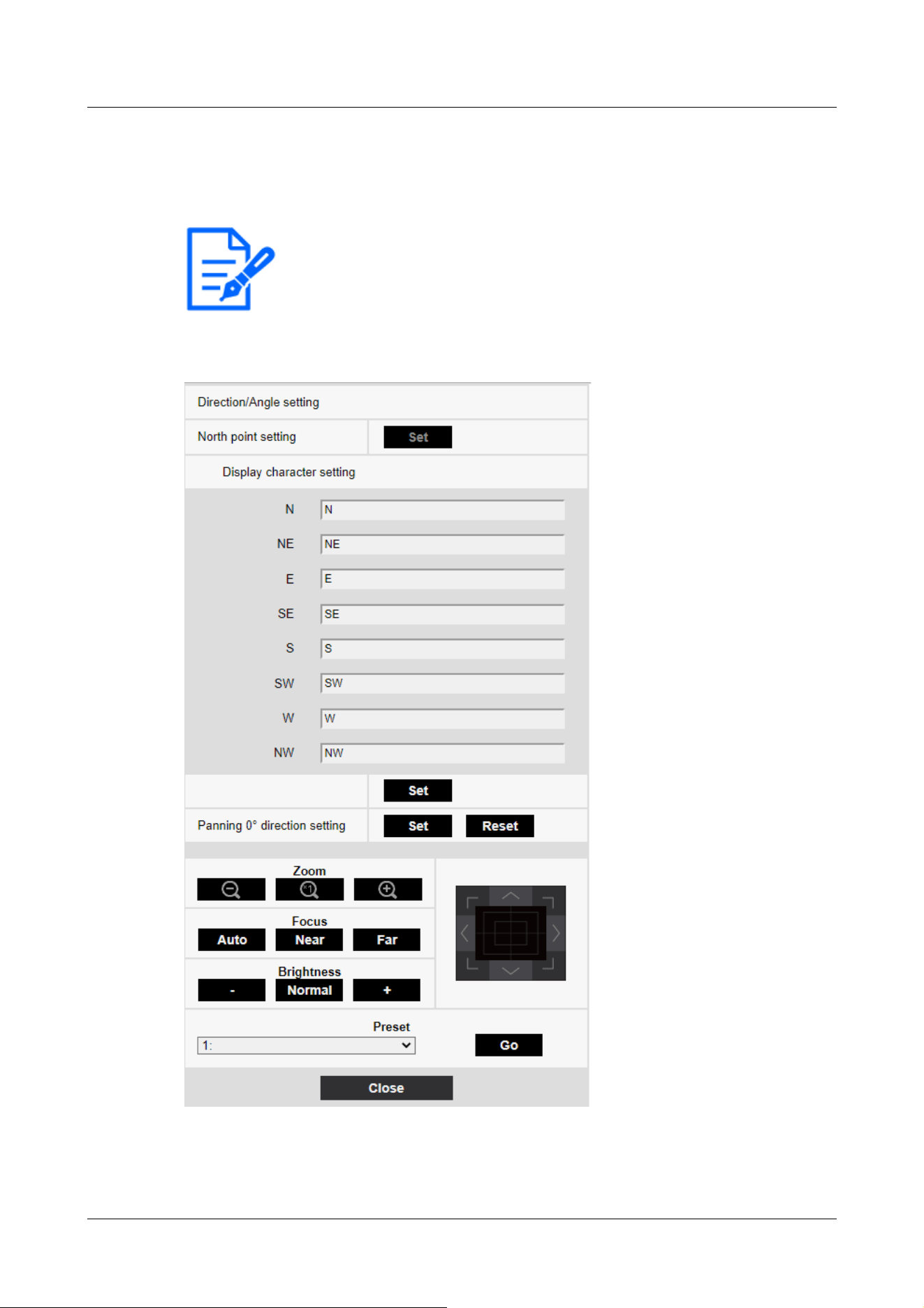
[Note:]
・The items that can be set differ depending on the function of the model.
・Refer to the catalog specifications for the functions installed in each model.
it moves to the punch position set to north.
→11.2 [Position] for setting positions
Rapid PTZ Cameras, Multi-directional + PTZ(PTZ part)
Indoor PTZ cameras
11 Set PTZ
11.2 [Position] for setting positions
396
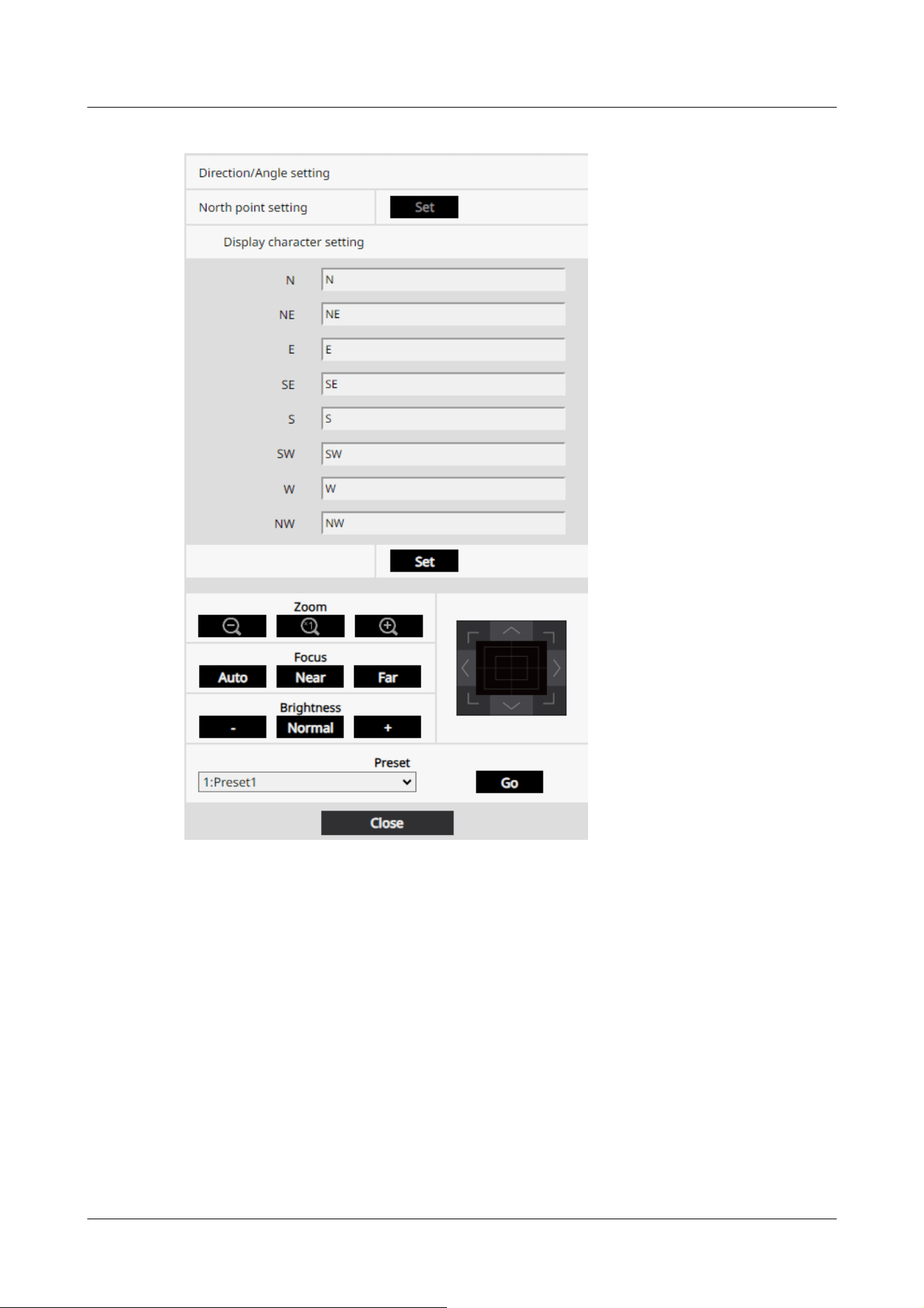
Direction/Angle setting
If the [Camera position display] on the [Cam. Function] tab of the PTZ page is set to [Direction
display], the 8-directions are displayed in the preset position title display position.
[North point setting]
Set the orientation to be displayed as north (N) by adjusting the orientation of the pan and
pressing [Set].
[Display character setting]
Individual names can be set for each direction/direction.
[N]:Set the north direction name.
11 Set PTZ
11.2 [Position] for setting positions
397

[Note:]
・Tilts are not set in the 0° direction.
・Changing the 0° direction of the pan does not change the position of the preset
position already set. The set auto pan turns within the same range as before the
change. Similarly, the same operation as before the change is performed for the
patrol setting.
[NE]:Set the name in the northeast direction.
[E]:Set the name in the east direction.
[SE]:Set the name in the southeast direction.
[S]:Set the name in the southern direction.
[SW]:Set the name in the southwest direction.
[W]:Set the name in the west direction.
[NW]:Set the name in the northwestern direction.
[Panning 0° direction setting]
Set the direction of the pan to 0°. If you adjust the field angle with the control pad/button and
click the [Set] button, the direction of the pan you are presently pointing to will be 0°. Press
[Reset] to return to the default settings.
[Zoom], [Focus], Control Pad/Button, [Brightness], and Move presets buttons
Please refer to the following instructions for operation.
→2.3.2 About live image pages
[Close] buttons
Click this button to close the direction/direction setting window.
11.2.6 Setting of pan/tilt range (pan/tilt range setting screen)
In the [Position] tab of the PTZ-page to the Advanced Settings tab of [Pan/tilt range setting]>>
Click the [Button].
→11.2 [Position] for setting positionsHere, the range of pan tilt is set.
11 Set PTZ
11.2 [Position] for setting positions
398
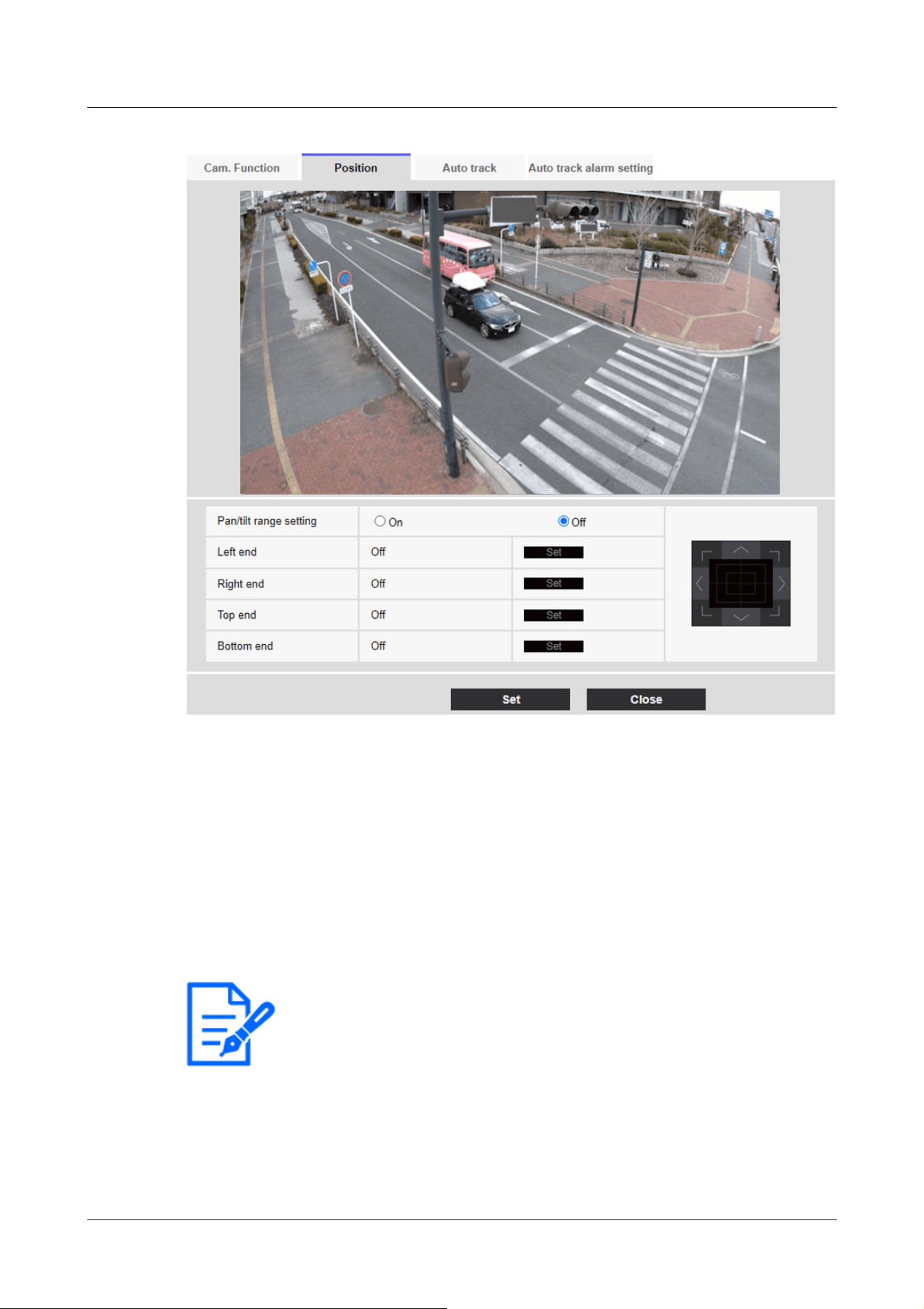
[Note:]
・The [Left end] angle should be smaller than the [Right end] angle and the
[Bottom end] angle should be larger than the [Top end] angle.
・Set [Pan/tilt range setting] on a screen that is not zoomed in.
If you set the display size to 1.0 times (x1) on the zoomed display, a larger area
than when the display was set (enlarged display) is displayed.
Pan/tilt range setting
On/Off sets whether to enable the range that restricts the pan tilt operation.
Set [On] and use the control pads/buttons to adjust the field angle to set [Left end], [Right end],
[Top end] and [Bottom end].
[Left end]/[Right end]/[Top end]/[Bottom end]
Adjust the angle of view with the control pad/button and press the [Set] button to view the angle
at the set position.
11 Set PTZ
11.2 [Position] for setting positions
399

・Incorrect settings may cause you to view unexpected camera images. After
setting, be sure to check the image using the pan tilt operation.
・Configure [Pan/tilt range setting] prior to setting the preset position. If the
preset position is outside the range of [Pan/tilt range setting], the preset position
stops at the end of the range.
・When the pantilt range setting screen is displayed, the zoom factor is 1.0 times.
During [Pan/tilt range setting], [PT LIMIT SETTING] is displayed in the images.
-If you do not operate for 5 minutes, the [Pan/tilt range setting] [Set] will be
disabled. To continue the operation, display the [Pan/tilt range setting] window
again and set it.
[Note:]
・Auto track setup is not available under the following conditions.
-When [16:9 mode(60fps mode)], [16:9 mode(50fps mode)], [4:3 mode(15fps
mode)] or [4:3 mode(12.5fps mode)] is selected for [Image capture mode]
・Under the following conditions, auto track setup is available, but the auto track
performance will lower.
-When [Maximum shutter] of [Image adjust] - [Light control mode] is set to
[Max.2/30s], [Max.4/30s], [Max.6/30s], [Max.10/30s], or [Max. 16/30s].
(For auto track, the [Max.1/30s] setting is recommended.)
・If the automatic tracking function is used for a long time, the drive parts may be
consumed and the replacement cycle of consumables may be faster. For
consumables, refer to the Web Guide.
11.3 Set auto-tracking (Auto-tracking screen)
Click on the [Auto track setting] tab of the PTZ page.
Here, you can register, change, or delete auto tracking settings.
Automatic tracking is a function that automatically tracks and shoots an object when it is detected
in a predetermined auto pan, preset sequence/preset position, patrol, or area.
11 Set PTZ
11.3 Set auto-tracking (Auto-tracking screen)
400
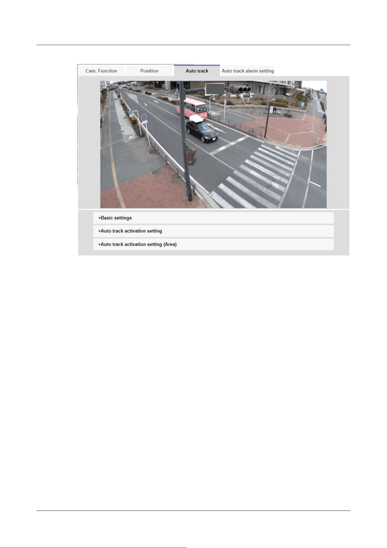
Basic settings
[Detection object]
The object to be detected can be selected. You can select multiple objects.
[Human]:Automatic tracking is performed when a person is detected.
[Vehicle]:Automatic tracking is performed when a car is detected.
[Bicycle]:Automatic tracking is performed when a motorcycle is detected.
[Object size]
Select the size at tracking from the following.
[Small (1/4 of the image)]:Zoom the tracking object to the monitor screen up to about 1/4
(vertical) size.
[Medium (1/2 of the image)]:Zoom the tracking object to the monitor screen up to about 1/2
(vertical) size.
[Large (3/4 of the image)]:Zoom the tracking object to the monitor screen up to approximately
3/4 (vertical) size.
[No size adjustment]:Zoom control is not performed during tracking.
11 Set PTZ
11.3 Set auto-tracking (Auto-tracking screen)
401

[Note:]
・The size is only a guide. Depending on the environmental conditions and tracking
conditions, the assumed size may not be achieved.
・Increasing the size of the object to be tracked reduces the tracking performance.
[Note:]
・The lower the sensitivity, the less false detection due to wooden shaking, but the
lower the tracking performance. On the other hand, higher sensitivity improves
tracking performance, but it also increases false detection. Set according to the
environment.
[Note:]
・After the maximum tracking time, the camera stops in that position. When the
auto mode operation is restored, the self-return time is counted and the auto
mode operation is restored after the tracking is stopped by setting the self-return.
[Sensitivity]
Select the sensitivity during tracking from the following.
[High]/[Middle]/[Low]
[Longest tracking time]
Select the time from below from the start of auto-tracking to forced termination.
[Off(Unlimited)]/[10s]/[20s]/[30s]/[40s]/[50s]/[1min]/[2min]/[3min]/[5min]/[10min]
[Auto track data in video stream]
Select whether to send the superimposed image data by adding auto-tracking information to the
image.
[Off]:Automatic tracking information is not added to the image.
[On]:This feature adds automatic tracking information to images, but does not display target
frames for objects under automatic tracking in live pictures.
[On (with track video display)]:This feature adds auto-tracking information to images and displays
the target frame for objects under auto-tracking in live pictures.
Auto tracking start setting
[Auto pan]
Select whether or not to automatically track the user during auto panning.
[Enable]:Automatic tracking is started during auto panning.
[Disable]:Automatic tracking is not started during auto pan.
11 Set PTZ
11.3 Set auto-tracking (Auto-tracking screen)
402

[Important]
・In the following cases, the target subject may not be tracked or may malfunction.
Low contrast between the subject and the background
If the dome is moist or dirty
Large variation in illumination
When there are many movements other than the subject
[Preset sequence/Preset position]
Choose whether to auto track in preset sequence or in preset position.
[Enable]:Automatic tracking is started during the preset sequence or in the preset position.
[Disable]:Automatic tracking is not started during preset sequence or preset position.
[Preset position selection]
[Select all] buttons:Select all preset positions.
[Cancel all] buttons:You can release all selections.
1~256:Toggle the corresponding preset position [On] or [Off].
[Set] buttons:Save the settings of the created preset sequence.
[Patrol]
Select whether or not to automatically track when a tracking target is detected during patrol.
[Enable]:Start automatic tracking during patrol.
[Disable]:Automatic tracking is not started during patrol.
Auto Track Activation Setting (Area)
[Area select]
When [Detection object] appears in the specified area, auto tracking can be started.
Eight areas can be set.
[Set] buttons:Set the auto tracking start area to the specified area No.
[Delete] buttons:Deletes the auto tracking area set to the specified area number.
[Cancel] buttons:Cancels the setting of the currently set auto tracking area.
[Zoom], [Focus], Control Pad/Button, [Brightness], and Move presets buttons
Please refer to the following instructions for operation.
→2.3.2 About live image pages
[Close] buttons
Click this button to close the Auto Tracking Settings window.
11 Set PTZ
11.3 Set auto-tracking (Auto-tracking screen)
403
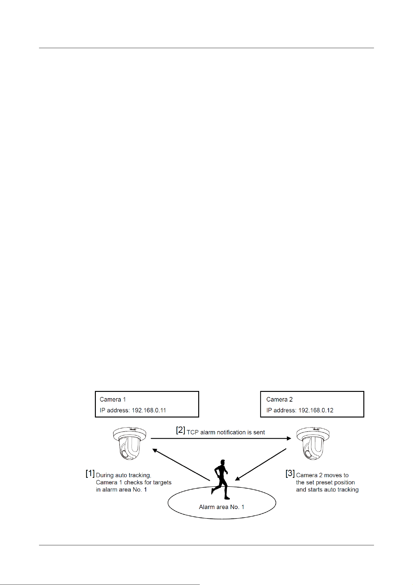
When the subject moves directly below the camera
If flickering is severe
-reflection of light through windows, reflection of road surfaces, reflection of
backlight into the dome, etc.
When a tracking object is hidden in the pole or behind the object.
-when multiple subjects intersect or crowd
When the subject moves too fast or too slowly
-if the subject is too small or too large
If the camera is swaying
If the weather is very bad
-when the image correction function is ON
・It is recommended to use the product in the following installation environment to
increase the detection accuracy.
--more than about 1/5 (vertical) of the size of the monitor screen
・We shall not be liable for any inconvenience, damage, or damage caused by the
automatic tracking function settings or the results.
Procedure for setting automatic tracking linkage
When two or more cameras with automatic tracking function are used, the tracking of objects can
be coordinated between the cameras.
(Automatic Tracking Coordination Function)
As an example, as shown in the figure below, the procedure for setting the connection from
Camera 1 (IP address: 192.168.0.11) to Camera 2 (IP address: 192.168.0.12) when the tracking
target enters the alarm area No.1.
11 Set PTZ
11.3 Set auto-tracking (Auto-tracking screen)
404

1 Set the alarm area for the area for which automatic tracking is desired in Camera 1.
① The auto tracking setting screen is displayed.
② Select [On(In preset alarm area)] in [Auto track alarm] and press [Set].
③ In the Alarm area [Area select], select 1 from the [Area No.] pull-down.
④ While looking at the screen, perform pan tilt zoom to set the alarm area.
⑤ Press [Set].
2 Set the preset position to move when receiving the unique notification command in camera 2.
(Set the preset position so that the alarm area No.1 of Camera 1 set in step 1 enters the
screen.)
① The preset position setting screen is displayed.
→11.2.1 Set the preset position (preset position setting screen)
② Select the desired number from the [Preset] pull-down list.
③ While viewing the screen, set the preset position by using the pan tilt zoom.
④ Press [Register].
3 Set Camera 1 (IP address: 192.168.0.11) to notify the command.
① The Alarm Page [Notification] window is displayed.
→14.12 [Notification] to set alarm notification
② Set [TCP alarm notification] to [On] and press [Set].
③ In the [Destination of notification] [Notify Destination 1] (which may be selected), check
the [Alarm] checkbox and insert 192.168.0.12 in the [Destination address].
④ Set [Auto track cooperation] to [On] and select Alarm area No. 1.
⑤ Press [Set].
4 Set Camera 2 (IP address: 192.168.0.12) to receive the command.
① The Alarm Page [Alarm] window is displayed.
→14.1 [Alarm] to set alarm operation
② Set the [Alarm] [Command alarm] to [On] and press [Set].
③ Set the [Camera action on alarm] [Command alarm] to [Preset per sender] and press
[Preset per sender].
④ On the Preset by Source window, check Auto Tracking of [Source Address 1] (any Source
Address may be selected), enter the Source Address 192.168.0.11 (Camera 1), select the
preset position to move when receiving the command set in step 2, click [Set], and close
the pages.
→14.4.1 Set the preset position by source (screen for setting preset position by source)
⑤ Press [Set].
5 By starting the automatic tracking operation of camera 1, the automatic tracking linkage
function can be used.
11 Set PTZ
11.3 Set auto-tracking (Auto-tracking screen)
405

[Note:]
・Automatic tracking is not available in the following cases.
-When [Image capture mode] is [16:9 (60 fps mode)], [16:9 (50 fps mode)], [4:3
(15 fps mode)], [4:3 (12.5 fps mode)]
-When the [Light control mode] [Maximum shutter] of [Image adjust] is set to the
following
Maximum 2/30s/Maximum 4/30s/Maximum 6/30s/Maximum 10/30s/Maximum
16/30s
・If the automatic tracking function is used for a long time, the drive parts may be
consumed and the replacement cycle of consumables may be faster. For
consumables, refer to the Web Guide.
11.4 Set Auto Track Alarm (Auto Track Alarm screen)
Click on the [Auto track alarm setting] tab of the PTZ page. Here, you can set the automatic
tracking alarm.
The auto tracking function automatically tracks and shoots the subject when movement is
detected in the pre-set alarm area.
11 Set PTZ
11.4 Set Auto Track Alarm (Auto Track Alarm screen)
406
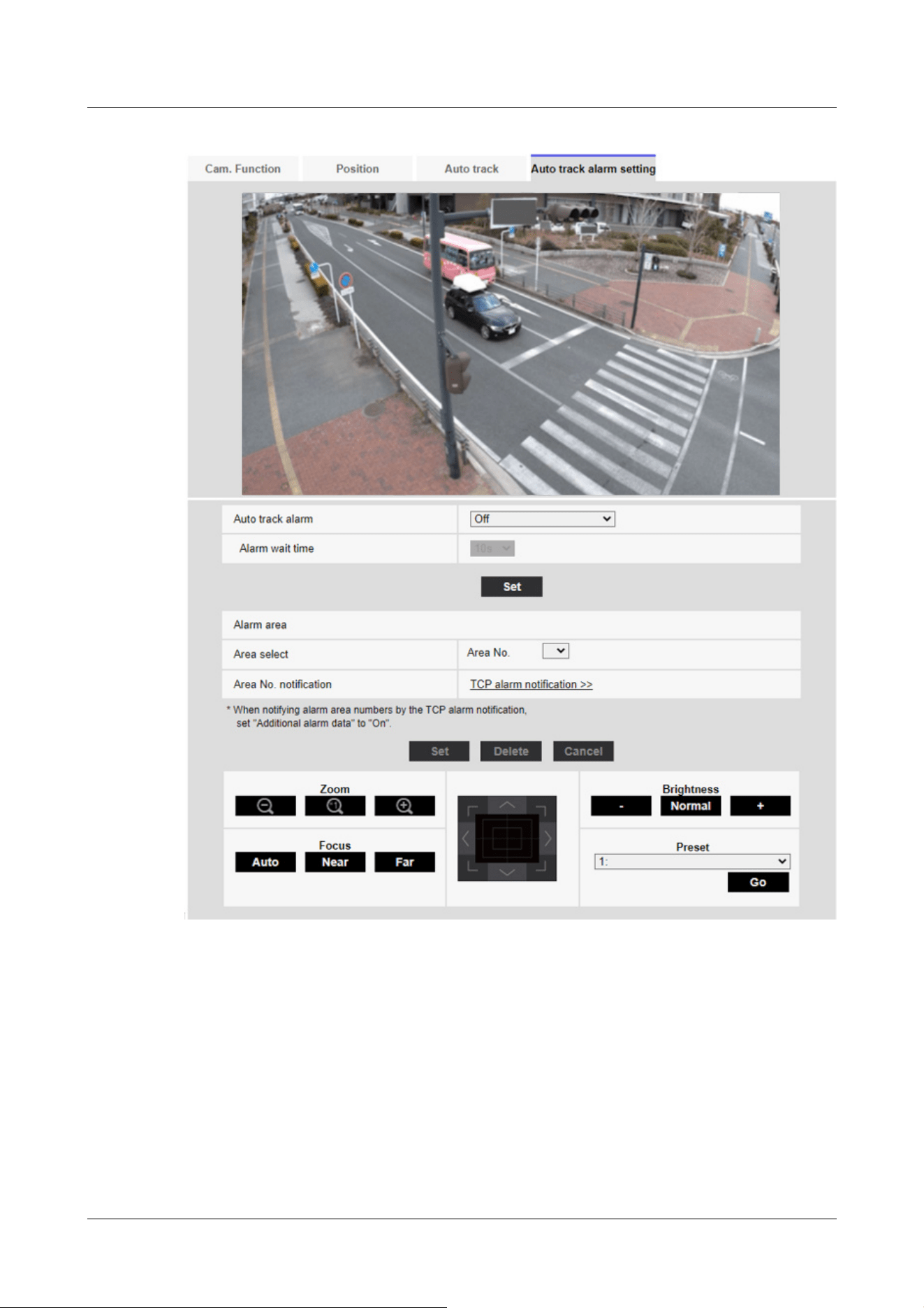
[Auto track alarm]
Select the alarm during automatic tracking from the following.
[Off]:Alarm is not output.
[On (Immediate)]:During automatic tracking, the alarm will continue to be output. The output
interval is every 5 seconds.
[On (After alarm wait time)]:The alarm is output only once when automatic tracking continues for
a certain period of time.
[On (In preset alarm area)]:During automatic tracking, the alarm is output only once when a
11 Set PTZ
11.4 Set Auto Track Alarm (Auto Track Alarm screen)
407

[Note:]
・The alarm area cannot be set individually for each preset position. The
configured area is valid for all preset positions.
tracking object is in the set alarm area. Refer to [Alarm area] for the alarm settings.
[Alarm wait time]
If [Auto track alarm] is set to [On(After alarm wait time)], select the set time from the following.
[1s]/ [10s]/ [30s]/ [1min]/ [3min]/ [5min]
Alarm area
[Area select]
Click [▼] on the [Area No.] and select the area number (1 to 8) to be set. The [*] mark to the
right of the area No. indicates that the area is already stored. The alarm area is enabled when On
(when the alarm area enters) is selected for automatic tracking alarm.
[Area No. notification]
Clicking [TCP alarm notification setup] displays the [Notification] tabs on the Alarm Page.
→14.12 [Notification] to set alarm notification
11 Set PTZ
11.4 Set Auto Track Alarm (Auto Track Alarm screen)
408

[Note:]
・The items that can be set differ depending on the function of the model.
・Refer to the catalog specifications for the functions installed in each model.
12 Set Zoom
The Zoom page is used to set Zoom/Focus, the camera operation, and preset position.
The Zoom pages consist of the [Zoom/Focus], [Cam. Function], and [Position] tabs.
12.1 [Zoom/Focus] for setting Zoom/Focus
Click on the [Cam. Function] tab of the PTZ page. Refer to the following how to display and
operate the Advanced menu.
→5.1 How to display
→5.2 How to operate
Use Zoom to adjust the angle of view of the displayed image.
Adjust the focus by moving the lens focus to the optimal position. It can be adjusted manually.
12 Set Zoom
12.1 [Zoom/Focus] for setting Zoom/Focus
409
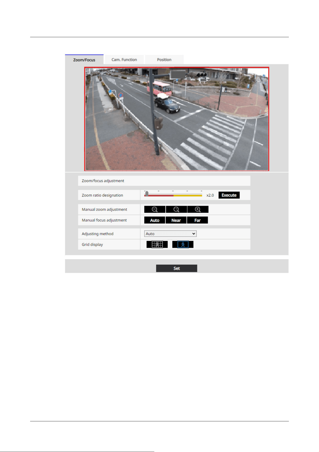
[Zoom ratio designation]
Adjust the zoom and focus simultaneously.
Press the slider bar to zoom in or out the angle adjustment frame in the image.
When you adjust the zoom (magnification) in the "telephoto" direction, only the image adjustment
frame is reduced and you can specify the zoom (magnification) while checking the angle of view
after the zoom is executed.
When the zoom (magnification) is adjusted in the "Wide angle" direction, the image itself is
reduced or the frame for the zoom angle adjustment is enlarged. You can specify the zoom
(magnification) while checking the image size after the zoom is executed.
Adjust the angle of view adjustment frame, and click [Execute] to zoom. Then, automatically
adjust the focus to the object in the center of the window using the auto focus function.
12 Set Zoom
12.1 [Zoom/Focus] for setting Zoom/Focus
410

[Note:]
・The maximum magnification of the EX zoom depends on the model and the [Image
capture mode] you are configuring.
・Refer to the catalog specifications for the maximum magnification of each model.
・In the [Manual zoom adjustment] Buttons, When you press buttons, [Zoom
ratio designation] cannot be operated. To perform [Zoom ratio designation], click
the "Read" button or click the X1 button on the [Manual zoom adjustment].
・[AI Outdoor IR BulletX] If [Stabilizer] is set to [On], the maximum zoom factor is
limited.
[Important]
・When Digital zoom is set with the VIQS area, Privacy zone, VMD area, SCD
area, and mask area set, the position is misaligned. Therefore, set the Digital
zoom and then set each area.
→10.4.7 Set up VIQS
→10.4.6 Setting the privacy zone (Privacy zone setting screen)
→14.5 [VMD area] for setting motion detection
→14.7 [SCD area] to set up undesired detection
→10.4.2 Set the mask area
[Note:]
・One-click on the [Near] or [Far] buttons may appear to have no change in focus
due to trace adjustments. If you want to move the focus position large, press and
hold the button for a long time.
・[AI Outdoor IR BulletX] If [Stabilizer] is set to [On], the maximum zoom factor is
limited.
[Manual zoom adjustment]
Adjust the zoom manually.
: Adjust the zoom factor to 1.0 times in the [Wide Angle] direction.
: Zoom (magnification) is 1.0 times.
: Adjust the zoom factor in the [Telescope] direction.
[Manual focus adjustment]
Adjust the focus manually.
[Auto]: Adjust the focus to the auto.
[Near]: Adjust the focus to the [Near].
[Far]: Adjust the focus to the [Far].
12 Set Zoom
12.1 [Zoom/Focus] for setting Zoom/Focus
411

[Note:]
・Use [Fixed focus shift(Normal)] in object where there are spotlights, such as
streetlights, or in situations where there is a lot of traffic, auto focus may not
work. When the zoom factor is 10x or less, [Fixed focus shift(Normal)] is
recommended.
・At zoom magnifications greater than 10x, the optimum settings vary depending
on object, so try [Fix] or [Fixed focus shift(Normal)] and use a setting that
matches the focus.
[Important]
・If you cannot adjust the focus automatically when switching between color images
and black and white images in [Auto] settings, set to [Fix] or [Fixed focus
shift(Normal)].
[Focusing at Day & Night switching]
Select the focus adjustment method when switching between color image and black-and-white
image from the following.
For details, refer to our technical information website <Control No. C0315>.
[Auto]:The focus is automatically adjusted when the color/black-and-white settings are changed
from the focus-adjusted image. When the original color/black/white status is changed, the focus
position is returned to the last one.
[Fix]:The focus is fixed at the position where the focus was adjusted by auto focus or manually
regardless of the color/black-and-white condition.
[Fixed focus shift(Normal)]:Moves the focus to the appropriate position according to the lens.
[Fixed focus shift(LPR)]:Focus is moved by a fixed amount to a position suitable for license plate
identification according to the lenses.
[Grid display]
You can switch on/off the grid view that can be used to adjust the position of the machine when
using Extension software. For adjusted sizes for each Extension software, please refer to our
Technical Information website<Control No.: C0320>.
12.2 [Cam. Function] for setting the operation of cameras
Click on the [Cam. Function] tab of the Zoom page. Refer to the following how to display and
operate the Advanced menu.
12 Set Zoom
12.2 [Cam. Function] for setting the operation of cameras
412
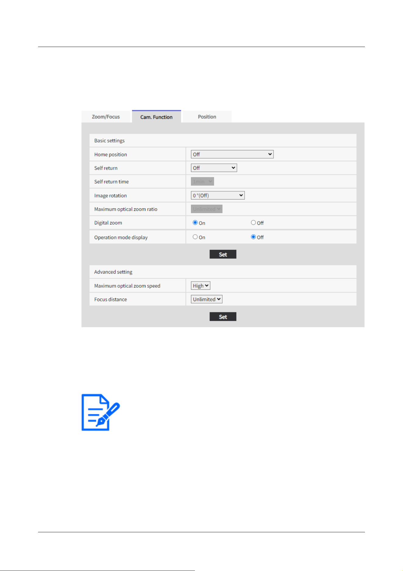
[Note:]
・If you want to move to the home position when the power is turned on, set
[HomePosition] to [Self return].
→5.1 How to display
→5.2 How to operate
This section sets the operation of the camera.
[Home position]
You can set the preset position as the home position.
When the home position is set, [H] is displayed next to the preset position number.
→12.3.1 Set the preset position (preset position setting screen)
[Self return]
When the time set by [Self return time] has elapsed after manual operation, the camera can
automatically return to one of the following modes of operation.
[Off]:Do not perform self-return.
[Home position]:After the set time has elapsed, the watch returns to the home position.
12 Set Zoom
12.2 [Cam. Function] for setting the operation of cameras
413

[Note:]
・If you want to perform the above operations when turning on the power, it is
convenient to use the self-turn function.
・The Self-turn function works even when the Setup menu is displayed.
・[Preset sequence] can be set only when the preset sequence is set.
→12.3.2 Set the preset sequence setting (preset sequence setting screen)
[Important]
・If the [Image rotation] setting is changed with the following area set, the set area
will be misaligned. Set [Image rotation] and then set the respective areas.
-Privacy zone
-VMD area
-SCD area
-VIQS area
-Mask area
-overlay image
-Focus frame
・If [Image rotation] is set to [90°] or [270°], the on-screen characters may be
broken depending on the [Character size] setting and the number of characters.
・When [Image rotation] is set to [90°] and [270°], the positions that can be set
to [Date/time position] and [Camera title position] are limited to [Upper left] and
[Lower left].
・[AI Outdoor IR BulletX] When [Stabilizer] is [On] and [Image rotation] is set to
[90°] or [270°] from an external device, the system automatically restarts.
・[AI Outdoor IR Bullet] When [Image rotation] is set to [90°] or [270°],
[Stabilizer] cannot be used.
・[AI Outdoor IR BulletX] When [Image rotation] is set to [90°] or [270°] and
320x180, QVGA images are displayed, characters in the images may be cut off.
[Preset Sequence]:Sequence operation starts when the set time elapses.
[Self return time]
After the manual operation is completed, select the time from the following to return to the
operation set by [Self return].
[10s]/ [20s]/ [30s]/ [1min]/ [2min]/ [3min]/ [5min]/ [10min]/ [20min]/ [30min]/ [60min]
[Image rotation]
Select from [0 °(Off)], [90°] and [180 °(Upside-down)], and [270°].
12 Set Zoom
12.2 [Cam. Function] for setting the operation of cameras
414

・[AI Outdoor IR BulletS-8M] When [Image rotation] is set to [90°] or [270°],
the frame rate is limited to a maximum of 15fps (maximum 12.5fps in 25fps mode).
[Note:]
・Depending on the [Image capture mode], you may not be able to set the [Image
Rotation] to [90°] or [270°].
・If [Image capture size] is 320 x 180, [Image rotation] cannot be set to [90°] or
[270°].
・[AI Outdoor IR BulletX] Even when [Image capture size] is set to 320x180, you
can set [Image rotation] to [90°] or [270°].
[Note:]
・When [On] is set to Digital Zoom, it stops once just before the Digital Zoom
magnification changes during the zoom operation.
Operation mode Display
[Maximum optical zoom ratio]
Select the maximum zoom ratio for the optical zoom from the following. Refer to the catalog
specifications for the installed optical zoom ratio.
・Optical zoom: 10x model x1/x2/x3/x4/x5/x6/x7/x8/x9/x10/unlimited
・Optical zoom: 30x model x1/x2/x3/x4/x5/x6/x7/x8/x9/x10/x11/x12/x13/x14/x15/x16/x17/
x18/x19/x20/x21/x22/x24/x26/x27/x28/x29/unlimited
[Digital zoom]
Select the digital zoom setting from the following.
[On]:When the optical zoom is exceeded, digital zoom is performed.
[Off]:Digital zoom is not performed.
About Digital zoom
・Optical zoom: For a 10x model, x1 to x10 optical zoom, and more (up to x160) digital zoom are
performed.
・Optical zoom: For a 30x model, x1 to x30 optical zoom, and more (up to x480) digital zoom are
performed.
[Operation mode display]
Displays the operation mode when the camera is running automatically.
[On]:Displays the operating mode.
[Off]:The operation mode is not displayed.
12 Set Zoom
12.2 [Cam. Function] for setting the operation of cameras
415

During startup INITIAL
During the preset sequence PRESET SEQ
[Note:]
・[AI Outdoor IR Bullet-30x model] [1.5m] cannot be selected.
[Maximum optical zoom speed]
Select the Maximum optical zoom speed.
[High]/[Mid]/[Low]
[Focus distance]
If you have a object over the window or a different object over a short distance, it may be difficult
to focus on the object you want to view. If the camera is not focused properly, you can limit the
shortest shooting distance.
[Unlimited]/[1.5m]/ [3m]/ [5m]/ [10m]
12.3 [Position] for setting positions
Click on the [Position] tab of the Zoom page. Refer to the following how to display and operate the
Advanced menu.
→5.1 How to display
→5.2 How to operate
To Advanced Settings for each item>>Clicking this button displays the advanced settings window
in a separate window and allows you to set the settings while viewing the images displayed on the
[Position] tab.
Here, you can set preset position and preset sequence setting.
12 Set Zoom
12.3 [Position] for setting positions
416
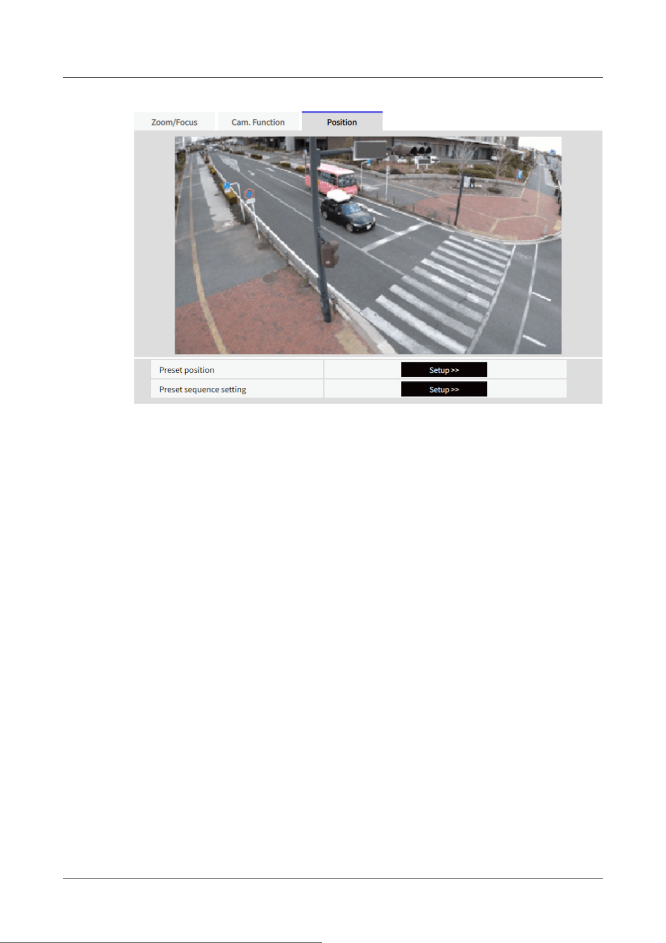
[Preset position]
To Advanced Settings>>When the button is clicked, the preset position setting window is
displayed in a separate window.
→12.3.1 Set the preset position (preset position setting screen)
[Preset sequence setting]
To Advanced Settings>>When the [button] is clicked, the preset sequence settings window is
displayed in a separate window.
→12.3.2 Set the preset sequence setting (preset sequence setting screen)
12.3.1 Set the preset position (preset position setting screen)
In the [Position] tab of the Zoom page to the Advanced Settings tab of [Preset position]>>Click
the [Button].
→12.3 [Position] for setting positions
Here, you can register, change, or delete the preset position.
If you adjust the focus, brightness, zoom, etc., the images on the [Position] tabs will be reflected
at the same time.
12 Set Zoom
12.3 [Position] for setting positions
417
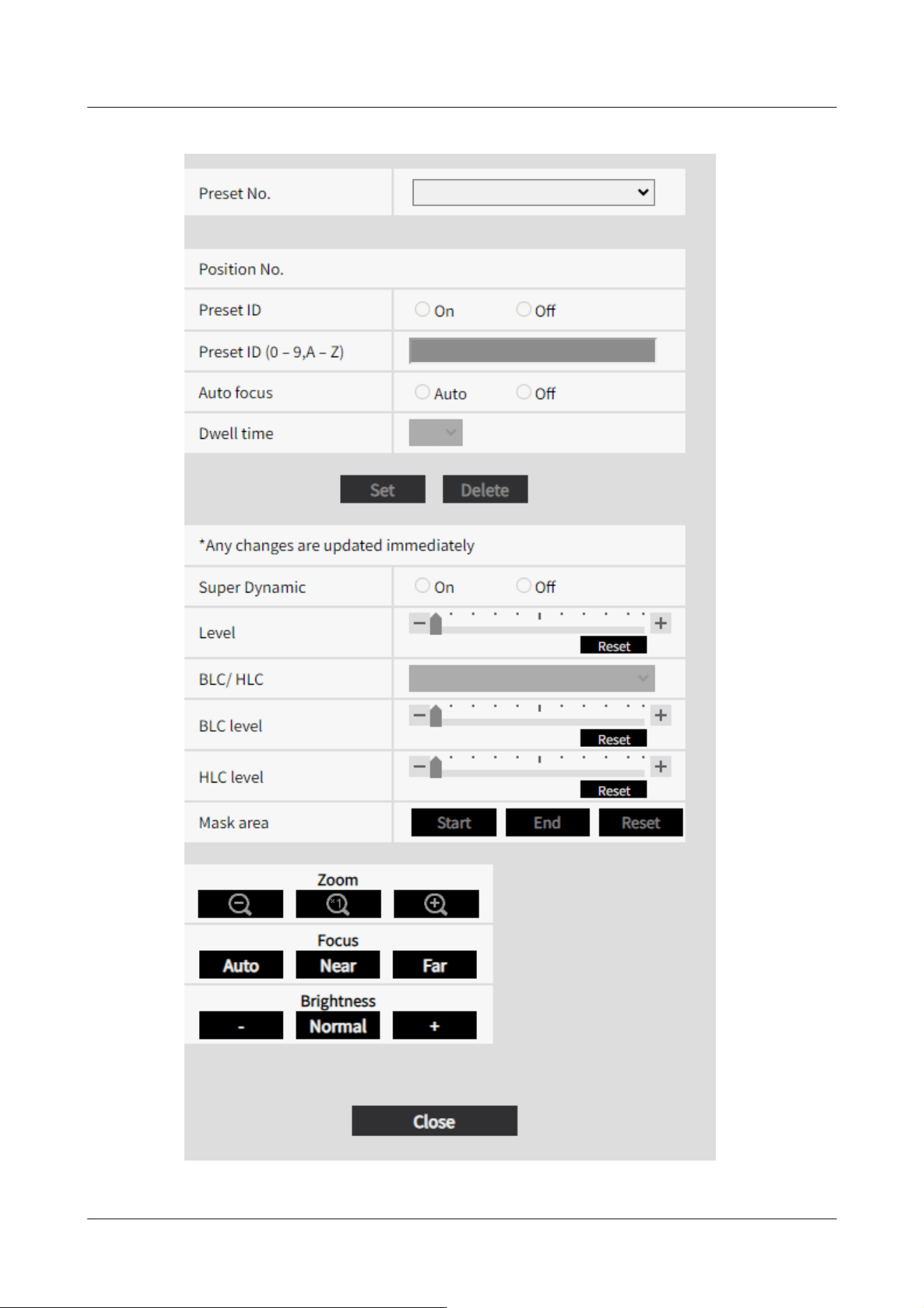
12 Set Zoom
12.3 [Position] for setting positions
418
[Important]
・Do not change other settings during preset position setting. The image may not
be displayed correctly.
・You can set a preset position up to half the maximum camera magnification.
・Up to 8 preset positions can be set.
[Note:]
・Depending on the operating environment (+5 °C or less as a guideline), the
speed of the preset movement may be slightly slower.
[Important]
・If you have configured [Preset ID (0 – 9,A – Z)] and [Preset ID], be
sure to press [Register].
[Note:]
・When set to [On], the position name is displayed where you set the position in
[Camera title position] on the [Basic] tab.
[Note:]
・The position name entered is displayed next to the preset position number in the
pull-down. If [Preset ID] is set to [On], it can also be displayed on the images.
Preset position setting
[Preset ID]
Use [On] and [Off] to set whether the position name is displayed. You can set for each preset
position.
[On]:Displays the position name.
[Off]:The position name is not displayed.
[Preset ID (0 – 9,A – Z)]
Enter the name to be displayed on the image. You can set for each preset position.
Number of characters that can be entered:0 to 40 characters
Input Characters:0-9 (single-byte), A-Z (single-byte, uppercase, lowercase), double-byte,
single-byte symbol ! " # $ % & ' ( ) * + , ‑ . / : ; = ?
[Auto focus]
12 Set Zoom
12.3 [Position] for setting positions
419

[Note:]
・When presetting a subject whose depth does not change, a subject whose
contrast is low, or a subject with high brightness such as a spotlight, etc., set
[Off] and register the preset position after setting the focus.
[Note:]
・Depending on the stop time setting, the watch may move to the next preset
position during auto focus operation.
・If the preset sequence function is used for a long time, the drive parts may be
consumed and the replacement cycle of consumables may be faster. For
consumables, refer to the Web Guide.
[Note:]
・Set [Super Dynamic] to [Off] when the following phenomena are observed
depending on the lighting condition.
-when flickering or color changes occur
-when noise is generated in the bright area of the screen
・If [Light control mode] is set to [Fix shutter], [Super Dynamic] cannot be set to
[On].
]
]
,
]
.
Use [Auto] and [Off] to set whether auto focus is performed after the preset is moved. You can set
for each preset position.
[Auto]:Auto focus is performed after the preset is moved.
[Off]:Auto focus is not performed after moving the preset.
[Dwell time]
During the preset sequence operation, select the time to reflect the image of each preset position
(the time when the camera stops rotating) from the following.
[5s]/ [10s]/ [15s]/ [20s]/ [25s]/ [30s]
[Super Dynamic]
You can set [On] or [Off] to activate the super dynamic function. You can set for each preset
position.
This cannot be set when [Image capture mode] is [16:9 mode(60fps mode)] or [16:9 mode(50fps
mode)].
See [What is Super Dynamic] for details on super dynamic.
[On]:The Super Dynamic function is activated.
[Off]:Stops the superdynamic function.
12 Set Zoom
12.3 [Position] for setting positions
420

・When [Stabilizer] is set to [On], the superdynamic setting is [Off].
・[Rapid PTZ-8M (4K)][Rapid PTZ-6M]If you switch the [Super Dynamic] from
[On] to [Off] or from [Off] to [On], the images may be distorted.
[Note:]
・[AI Outdoor IR BulletX-8M][AI Outdoor IR BulletX-5M][AI Outdoor IR
BulletS-8M][AI Outdoor IR BulletS-5M] If [Image adjust]'s [Super Dynamic] is
set to [On] and [Level] is set to 30 or higher, [Level] of [Preset position] operates
as 30.
→10.4.1 To adjust the image quality (image quality adjustment screen)
[Level]
Adjust the superdynamic level.
When the slider bar is moved in the [+] direction, you can shoot a subject with a large difference in
light and darkness without flipping white or shading black.
Move the slider bar in the [-] direction to take a full picture of the middle brightness.
Press [Reset] to return to the default settings.
[BLC/ HLC]
Select from the following. This setting is not available if [Super Dynamic] is set to [On] or
[Intelligent Auto] is set to [On].
[Back Light Correction (BLC)]:Enables the backlight correction function.
[Intensity correction]:Enables the high light correction function. Illumination compensation
suppresses bright lighting of subjects such as car headlights during nighttime.
[Off]:Stops the backlight compensation function and the intense light correction function.
[BLC level]
Adjust the backlight correction level.
Moving the slider bar in the [+] direction improves the backlight correction effect.
Moving the slider bar in the [-] direction reduces the effect of backlight correction.
Press [Reset] to return to the default settings.
[HLC level]
Adjust the intensity correction level.
Moving the slider bar in the [+] direction improves the effect of intense light correction.
Moving the slider bar in the [-] direction reduces the effect of intense light correction.
Press [Reset] to return to the default settings.
12 Set Zoom
12.3 [Position] for setting positions
421

[Note:]
・If [Image adjust] [Scene file] is set to other than [Scene file is not applied], [Super
Dynamic], [BLC/ HLC], and [Mask area] cannot be set.
[Mask area]
When the mask area is set, the set area can be masked and the light intensity can be adjusted. If
[Super Dynamic] is set to [On], it cannot be set.
For details on how to set the mask area, refer to the following.
→10.4.2 Set the mask area
[Zoom], [Focus], [Brightness] Button
Please refer to the following instructions for operation.
→10.4.6 Setting the privacy zone (Privacy zone setting screen)
[Set] buttons
Register the preset position.
[Delete] buttons
Deletes the preset position selected by the position number.
[Close] buttons
Click this button to close the preset position setting window.
Register the preset position
1 Select the position number.
[Position No.] shows the selected position number.
→12.3.1 Set the preset position (preset position setting screen)
If it is already registered, the camera moves to the preset position selected.
2 Adjust the zoom ratio of the camera to the angle of view you want to register.
3 If you want the position name to appear on the live image page, set [Preset ID] to [On] and
enter the position name.
4 Set Auto Focus or Stop Time.
5 Press [Register].
6 To set image quality for each position, set each item such as Super Dynamic. [Super
Dynamic], [BLC/ HLC], and [Mask area] are reflected immediately.
12 Set Zoom
12.3 [Position] for setting positions
422
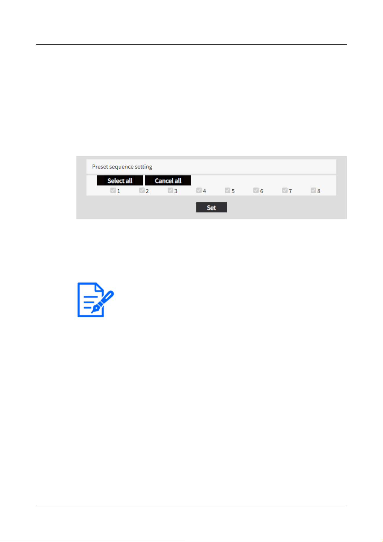
[Note:]
・When the preset sequence is activated, the registered preset positions are
moved from a younger number to a higher order.
・After moving to the trailing preset position, the system returns to the youngest
number and moves the preset position back in sequence.
12.3.2 Set the preset sequence setting (preset sequence setting screen)
To [Preset sequence setting] Advanced Settings on the [Position] tabs of Zoom pages>>Click the
[Button].
→12.3 [Position] for setting positions
Here, you can register, change, or delete the preset sequence.
Up to one preset sequences can be set.
Preset sequence setting
[Select all] button:Select all preset positions.
[Cancel all] button:You can release all selections.
1~8:Enables/disables the corresponding preset position.
[Set] button:Save the settings of the created preset sequence.
12 Set Zoom
12.3 [Position] for setting positions
423

[Note:]
・[New X Fixed-8MP][New X Fixed-6MP][New X Fixed-5MP][AI Outdoor IR
BulletX-8M][AI Outdoor IR BulletX-5M]If [Image capture mode] is set to [60fps
Mode] or [50fps Mode], [Multi-screen] cannot be used.
[Important]
・When accessing the camera using the HTTPS protocol, it is necessary to install
the pre-installed certificate or the CA certificate of the camera to display images
on the monitor. For how to install, refer to video clips <Control No.: P0002> and
<Control No.: P0003> on the support video page on our support website.
・This camera is specified when “selfcamera” is displayed for the IP address or host
name.
13 Configure the multi-screen settings[Multi-
screen]
The cameras from which images are to be displayed on a multi-screen can be registered on the
[Multi-screen] page.
→5.1 How to display
→5.2 How to operate
[IP address]
Enter the IP address or the host name of the camera to be used for the multi-screen. 4 cameras
can be registered as a group and up to 4 groups (16 cameras) can be registered.
When the HTTP port number for the camera of which images are to be displayed had been
changed, enter as follows:
Example of entry:
Example when entering an IPv4 address: http://192.168.0.10:8080
Example when entering an IPv6 address: http://[2001:db8:0:0:0:0:0:1]:8080
To access the cameras using the HTTPS protocol, enter as follows:
Example of entry: https://192.168.0.10/
Available number of characters: 1 - 128 characters
13 Configure the multi-screen settings[Multi-screen]
424

[Note:]
・When using the host name, it is necessary to configure the DNS settings of the
PC to be used for themulti-screen display. Refer to the network administrator for
information on the DNS setting of PCs.
[Note:]
・When selecting a 16 split-screen, some characters of the camera title to be
displayed may not be displayed.
・Even when [16:9] is selected for the aspect ratio, the multi-screen is displayed in
4:3.
[Camera title]
Enter the title of the camera. The entered camera title will be displayed on a multi-screen.
Available number of characters: 0 - 20 characters
Unavailable characters: " &
Initial display
[Layout]
Select the layout for the initial display from the following:
4 Screens(1-4)/ 4 Screens(5-8)/ 4 Screens(9-12)/ 4 Screens(13-16)/ 9 Screens(1-9)/ 9
Screens(10-16)/ 16 Screens
[Refresh interval]
MJPEG: Displays the camera image in the motion JPEG format (video).
Refresh interval : 1s/ Refresh interval : 3s/ Refresh interval : 5s/ Refresh interval : 10s/ Refresh
interval : 30s/ Refresh interval : 60s: Displays the JPEG format (still image) camera image in the
selected interval.
[Image capture size(4 Screens)]
Select the image capture size for 4 screens in initial display.
640x360/320x180
13 Configure the multi-screen settings[Multi-screen]
425

[Note:]
・The items that can be set differ depending on the function of the model.
・Refer to the catalog specifications for the functions installed in each model.
14 [Alarm] to set the alarm
The alarm page is used to set the alarm operation using the external I/O terminal of the camera,
the alarm image, the area to detect the alarm, and the alarm notification. The Alarm page consists
of the [Alarm], [VMD area], [SCD area], [Audio detection], [Impact detection], [Casing open
detection], and [Notification] tabs.
14.1 [Alarm] to set alarm operation
Click [Alarm] on the Alarm page. Refer to the following how to display and operate the Advanced
menu.
→5.1 How to display
→5.2 How to operate
This is used to set the operation when an alarm is detected. For the alarm image and output
terminal settings, refer to the following.
→14.4 [Alarm] to set alarm linkage operation
→14.2 [Alarm] for setting the output terminal
Alarm
[Terminal 1]
Set the operation of terminal 1.
[Off]:Not used
[Alarm input (TRM1)]:The alarm input is received. When Alarm is selected, a pull-down menu
([Close], [Open], [Close(Continue)], [Open(Continue)]) is displayed.
–[Close]:When the terminal status changes to [Close], an alarm is detected.
–[Open]:When the terminal status changes to [Open], an alarm is detected.
–[Close (Continue)]:When the terminal status changes to [Close], an alarm is detected. When the
terminal status is [Close], the alarm is detected periodically at intervals of no alarm detection
time.
14 [Alarm] to set the alarm
14.1 [Alarm] to set alarm operation
426

–[Open (continue)]:When the terminal status changes to [Open], an alarm is detected. When the
terminal status is [Open], the alarm is detected periodically at intervals of no alarm detection
time.
[Black and white switching input]:The black-and-white selector input is received. (When the input
is [On], the input is switched to black and white)
[Automatic Time Adjustment]:Time setting by terminal input is accepted. When the signal is
input, set to 00 minutes 00 seconds if the time difference from the normal time (00 minutes per
hour) is 29 minutes or less. In the case of returning the time less than 5 seconds during SD
recording, the time is not changed. Selecting Auto Time Adjustment displays the pull-down menu
for short circuit and release selection.
–[Close]:When the terminal status changes to [Close], the time is automatically adjusted.
–[Open]:When the terminal status changes to [Open], the time is automatically adjusted.
[Terminal 2]
Set the operation of terminal 2.
[Off]:Not used
[Alarm input (TRM2)]:The alarm input is received. When Alarm is selected, a pull-down menu
([Close], [Open], [Close(Continue)], [Open(Continue)]) is displayed.
–[Close]:When the terminal status changes to [Close], an alarm is detected.
–[Open]:When the terminal status changes to [Open], an alarm is detected.
–[Close (Continued)]:When the terminal status changes to [Close], an alarm is detected. When
the terminal status is [Close], the alarm is detected periodically at intervals of no alarm detection
time.
–[Open (continued)]:When the terminal status changes to [Open], an alarm is detected. When the
terminal status is [Open], the alarm is detected periodically at intervals of no alarm detection
time.
[Alarm Output]:Alarm outputs according to the setting in [Output terminal].
→14.2 [Alarm] for setting the output terminal
[Terminal 3]
Set the operation of terminal 3.
[Off]:Not used
[Alarm input (TRM3)]:The alarm input is received. When Alarm is selected, a pull-down menu
([Close], [Open], [Close(Continue)], [Open(Continue)]) is displayed.
–[Close]:When the terminal status changes to [Close], an alarm is detected.
–[Open]:When the terminal status changes to [Open], an alarm is detected.
–[Close (Continued)]:When the terminal status changes to [Close], an alarm is detected. When
the terminal status is [Close], the alarm is detected periodically at intervals of no alarm detection
14 [Alarm] to set the alarm
14.1 [Alarm] to set alarm operation
427

[Important]
・It takes approximately 100 ms or longer to detect an alarm input to a short circuit
(ON) or an alarm input to an open circuit (OFF) of the external I/O terminal. The
alarm input will not be detected until the time set by [Alarm deactivation time]
has elapsed.
[Note:]
・AUX is a camera terminal that can be operated (opened/closed) by the operator
from the live image page. For example, when you want to operate lighting in the
location where the camera is installed, you can operate it remotely by connecting
it to a lighting control device.
・For the input/output ratings of each terminal, refer to the installation manual of
the model.
time.
–[Open (continued)]:When the terminal status changes to [Open], an alarm is detected. When the
terminal status is [Open], the alarm is detected periodically at intervals of no alarm detection
time.
[Aux output]:AUX output is performed. The [AUX] buttons appear on the live picture pages.
[VMD alarm]
Clicking [VMD] displays the [VMD area] tabs on the Alarm Page.
→14.6 [VMD area] to set the motion detection area
[Scene change detection (SCD) alarm]
Clicking [SCD] displays the [SCD area] tabs on the Alarm Page.
→14.8 [SCD area] to set up SCD area
[Auto track alarm]
Clicking [Auto track setting] displays the [Auto track alarm setting] tabs for the PTZ pages.
→11.4 Set Auto Track Alarm (Auto Track Alarm screen)
[Audio detection alarm]
Clicking [Audio detection] displays the [Audio detection] tabs on the Alarm Page.
→14.9 [Audio detection] for setting sound detection
[Impact detection alarm]
Clicking [Impact detection] displays the [Impact detection] tabs on the Alarm Page.
→14.10 [Impact detection] for setting impact detection
[Casing open detection alarm]
14 [Alarm] to set the alarm
14.1 [Alarm] to set alarm operation
428

[Note:]
・Alarm detection time is managed for each alarm type. For example, the operation
detection alarm and disturbance detection alarm are detected even during the no
alarm detection time of the command alarm.
・[MULTI] The port numbers 32768 to 49151 cannot be set.
[Note:]
・When the alarm test function is executed, the computer detects the command
alarm.
This function can be used to record an SD Memory Card triggered by alarm
detection or to confirm notification to an external device. Use the external device
specified as the notification destination and the system log of this equipment to
check the related settings.
・The alarm test function cannot be generated more than once within the alarm
detection time.
Clicking [Casing open detection] displays the [Casing open detection] tabs on the Alarm Page.
→14.11 [Casing open detection] for setting opening detection
[Command alarm]
Use [On] or [Off] to specify whether or not to accept the command alarm.
Command alarm is a function to receive unique alarm notification from other cameras. When set to
[On], the alarms can be operated in conjunction with several cameras.
[Reception port]
Set the port number to which the command alarm is received.
Settable range:1~65535
The following port numbers cannot be set because they are used by this computer.
20、 21、 22、 23、 25、 42、 53、 67、 68、 69、 80、 110、 123、 161、 162、 443、 554、 995、 1883、
8883、 10669、 10670、 59000~61000
[Alarm deactivation time]
Sets the time when the alarm is detected and the detection operation is not executed. For
example, this setting prevents sending too much mail to a mobile terminal or a tablet terminal
when it is set to send mail notification by an alarm.
0.5s、 1 ~ 600s
[Alarm test]
Clicking [Execute] performs the alarm test function.
14 [Alarm] to set the alarm
14.1 [Alarm] to set alarm operation
429

[Important]
・To use this function correctly, format the SD Memory Card on your computer
before using the SD Memory Card.
[Note:]
・Operation time: For 6 years, the power-on time after the SD card is inserted into
the camera, and for 2000 times, the upper limit of the number of business SD
Memory Card (MLC type) rewrites is used as a guide, and this does not guarantee
a durability period.
・The output terminal and SD Memory Card Alarm use the same output terminal.
・When either an alarm or SD Memory Card alarm is activated, a signal is output to
14.2 [Alarm] for setting the output terminal
Click [Alarm] on the Alarm page. Refer to the following how to display and operate the Advanced
menu.
→5.1 How to display
→5.2 How to operate
Here, the output terminal is set.
Output terminal
For the output terminal function, the [Terminal 2] of the [Alarm] setting must be set to [Alarm
output].
[Terminal output upon alarm detection]
Sets on/off whether an alarm signal is output to the output terminal when an alarm is detected.
[SD memory card error]
The [On] or [Off] is used to determine whether to output signals to the output terminals when an
SD memory card alarm is detected.
SD Memory Card Alarm Detection Conditions: SD Memory Card error (write error, read error,
etc.), Operating time: 6 years, Overwrite count: 2,000 times
[On]:When the alarm condition is detected, a signal is output to the output terminal and [Alarm
notification] of the live picture is popupped.
[Off]:Stops detecting the alarm condition.
14 [Alarm] to set the alarm
14.2 [Alarm] for setting the output terminal
430

the output terminal.
・When an SD Memory Card Alarm is detected, the [Alarm Notice] on the live
image page is popped out. Click the [x] button of [Alarm notification] to clear the
[Alarm notification] display.
・The output signal output by the SD Memory Card alarm depends on the alarm
format setting.
In the case of latches: The output signal continues for the duration of the cause of
the SD Memory Card warning even after the alarm notification is cleared.
For pulses: The signal output of the output terminal continues while the cause of
the SD Memory Card warning persists even after the alarm notification is cleared.
However, when the time set in [Alarm output time] has elapsed, the signal output
of the output terminal stops.
[Note:]
・When set to [Open], the alarm will be output for approximately 20 seconds when
the power to the computer is turned on.
[Terminal state upon alarm detection]
Set the output terminal operation when an alarm is detected to either [Latch] or [Pulse].
[Latch]:When an alarm is detected, the alarm output terminal is set to [Terminal action upon
alarm detection] until [x] is clicked in [Alarm notification].
[Pulse]:When an alarm is detected, the terminal at the time of alarm outputting is set by [Terminal
action upon alarm detection] for the period set by [Pulse output width]. Click the [x] button of
[Alarm notification] to return the output terminal to the normal state.
[Terminal action upon alarm detection]
Set the output status of the alarm output from the output terminal by [Open] or [Close].
[Open]:Set the alarm output terminal to Open (usually Close).
[Close]:The terminal at the time of alarm output is closed (normally open).
[Pulse output width]
Sets the time when the alarm is output from the output terminal when [Pulse] is selected in
[Terminal state upon alarm detection].
Settable range:1~120s
14 [Alarm] to set the alarm
14.2 [Alarm] for setting the output terminal
431

[Note:]
・The AUX name can be changed when [Terminal 3] in the [Alarm] setting is set to
[AUX output].
・AUX is a camera terminal that can be operated (Open/Close) by the operator
from the live picture page. For example, when you want to operate lighting in the
location where the camera is installed, you can operate it remotely by connecting
it to a lighting control device.
14.3 [Alarm] to change the aux name
Click [Alarm] on the Alarm page. (See the following for how to display and operate the Advanced
menu.
→5.1 How to display
→5.2 How to operate
You can change the [AUX], [Open], and [Close] names for live picture pages.
AUX title
[AUX (Up to 10 characters)]
Enter the [AUX] name for the live picture page.
Characters that cannot be entered:Half-pitch symbol " &
[Open (Up to 5 characters)]
Enter the [Open] name for the [AUX] buttons on the live picture pages.
Characters that cannot be entered:Half-pitch symbol " &
[Close (Up to 5 characters)]
Enter the [Close] name for the [AUX] buttons on the live picture pages.
Characters that cannot be entered:Half-pitch symbol " &
14.4 [Alarm] to set alarm linkage operation
Click [Alarm] on the Alarm page. Refer to the following how to display and operate the Advanced
menu.
→5.1 How to display
14 [Alarm] to set the alarm
14.4 [Alarm] to set alarm linkage operation
432

[Note:]
・Refer to the catalog specifications for the functions installed in each model.
・[PTZ][AI Outdoor IR Bullet] [Terminal alarm 1], [Terminal alarm 2], [Terminal
alarm 3], [VMD alarm], [Scene change detection (SCD) alarm], [Audio detection
alarm], and [Command alarm] can only be set for PTZ cameras and AI Outdoor IR
Bullet Camera.
・[AI Outdoor IR Bullet] [Patrol 1], [Patrol 2], and [Patrol 3] cannot be set.
→5.2 How to operate
This section sets the function to operate in conjunction with the alarm.
[Terminal alarm 1]Select the action to be interlocked when terminal alarm 1 is detected from the
following. This can be set when [Terminal 1] of the alarm is set to [Alarm input(TRM1)].
[Off]:Interlock operation is not performed even if terminal alarm 1 is detected.
1~256:When the preset position registered in advance is selected, the watch moves to the preset
position when terminal alarm 1 is detected.
[Patrol 1]:When terminal alarm 1 is detected, patrol starts. *When Patrol 1 is not registered, it is
not displayed.
[Terminal alarm 2]
Select the action to be interlocked when terminal alarm 2 is detected from the following. This can
be set when [Terminal 2] of the alarm is set to [Alarm input(TRM2)].
[Off]:Interlock operation is not performed even if terminal alarm 2 is detected.
1~256:When the preset position registered in advance is selected, it moves to the position when
terminal alarm 2 is detected.
[Patrol 2]:When terminal alarm 2 is detected, patrol starts. *When Patrol 2 is not registered, it is
not displayed.
[Terminal alarm 3]
Select the action to interlock when terminal alarm 3 is detected from the following. This can be set
when [Terminal 3] of the alarm is set to [Alarm input(TRM3)].
[Off]:Interlock operation is not performed even if terminal alarm 3 is detected.
1~256:Select the preset position registered beforehand to move to the position when terminal
alarm 3 is detected.
[Patrol 3]:When terminal alarm 3 is detected, patrol starts. *When Patrol 3 is not registered, it is
not displayed.
[VMD alarm]
14 [Alarm] to set the alarm
14.4 [Alarm] to set alarm linkage operation
433

Select the action to be linked to the alarm detected by the motion detector from the following.
[Off]:When an alarm is detected by the motion detector, interlock operation is not performed.
1~256:Selecting the preset position registered beforehand moves the watch to the position when
an alarm is detected by the motion detector.
[Patrol 1]:When an alarm is detected by the motion detector, a patrol is started. *When Patrol 1
is not registered, it is not displayed.
[Scene change detection (SCD) alarm]
Select the action to be interlocked when an alarm is detected by the undesired signal detection
from the following.
[Off]:Interlock operation is not performed even if an alarm is detected by undesired signal detection.
1~256:When the preset position registered in advance is selected, the watch moves to the preset
position when an alarm due to disturbance detection is detected.
[Patrol 1]:When an alarm is detected by the disturbance detection, a patrol is started. *When
Patrol 1 is not registered, it is not displayed.
[Audio detection alarm]
Select the action to be linked to the alarm detected by the sound detection from the following.
[Off]:The product does not perform interlocked operation even if an alarm is detected by sound
detection.
1~256:When the preset position registered in advance is selected, the watch moves to the preset
position when an alarm is detected.
[Patrol 1]:When an alarm is detected by sound detection, patrol is started. *When Patrol 1 is not
registered, it is not displayed.
[Command alarm]
Select the action to be linked to the alarm by the command alarm from the following. This can be
set when [Command alarm] is set to [On].
[Off]:The product does not operate in conjunction with the command alarm.
1~256:Selecting the preset position registered in advance moves the camera to the position when
a command alarm is detected.
[Patrol 1]:When a command alarm is detected, a patrol is started. *When Patrol 1 is not
registered, it is not displayed.
Source-specific preset position:Register the address of the sender of the command alarm and the
preset position corresponding to that address, and move to that position when the alarm is
detected by the command alarm.
When [Preset per sender] is clicked, a separate window opens showing the settings for the
source-specific preset position.
→14.4.1 Set the preset position by source (screen for setting preset position by source)
14 [Alarm] to set the alarm
14.4 [Alarm] to set alarm linkage operation
434

[Note:]
・[MULTI_PTZ] Only Multi-directional cameras with integrated Multi-directional/
PTZ cameras can be set to [Action at the time of a command alarm].
Command Alarm Action-Source Address
The IP address of the PTZ camera for the Multi-directional/PTZ integrated camera is displayed.
Operation at Command AlarmInterlocked operation
Select the action linked to the command alarm when received from the following.
[Off]:Interlock operation is not performed even if a command alarm is received.
[Alarm interlock]:Alarm operation is performed after the command alarm is received.
[Switching between black and white]:Switches between black and white after receiving the
command alarm.
[Automatic Time Adjustment]:Adjusts the time after the command alarm is received.
[Alarm E-mail notification]
When [E-mail notification setup] is clicked, the setting window for the e-mail when the alarm is
generated is displayed in a separate window.
→14.4.2 Mail sending when an alarm is generated
[Alarm image FTP/SFTP transmission]
When [FTP/SFTP setup] is clicked, a separate window is displayed for FTP/SFTP sending when
an alarm is generated.
→14.4.3 Set up FTP/SFTP transmission when an alarm is generated
[Alarm image recording(SD memory card)]
When [SD memory card setup] is clicked, the settings for recording to the SD Memory Card when
an alarm is generated are displayed in a separate window.
→14.4.4 Sets recording data to SD Memory Card when alarm is generated.
[TCP alarm notification]
When [TCP alarm notification setup] is clicked, the setting window for sending unique alarm
notification when alarm is generated is displayed in a separate window.
→14.4.5 Sets unique alarm notification when an alarm is generated.
[HTTP alarm notification]
When [HTTP alarm notification setup] is clicked, the setting window for sending HTTP alarm
notification when alarm is generated is displayed in a separate window.
→14.4.6 Sets HTTP alarm notification when an alarm is generated.
[SNMP transmission upon alarm detection]
When [To SNMP setting] is clicked, the setting window for sending SNMP when an alarm is
14 [Alarm] to set the alarm
14.4 [Alarm] to set alarm linkage operation
435
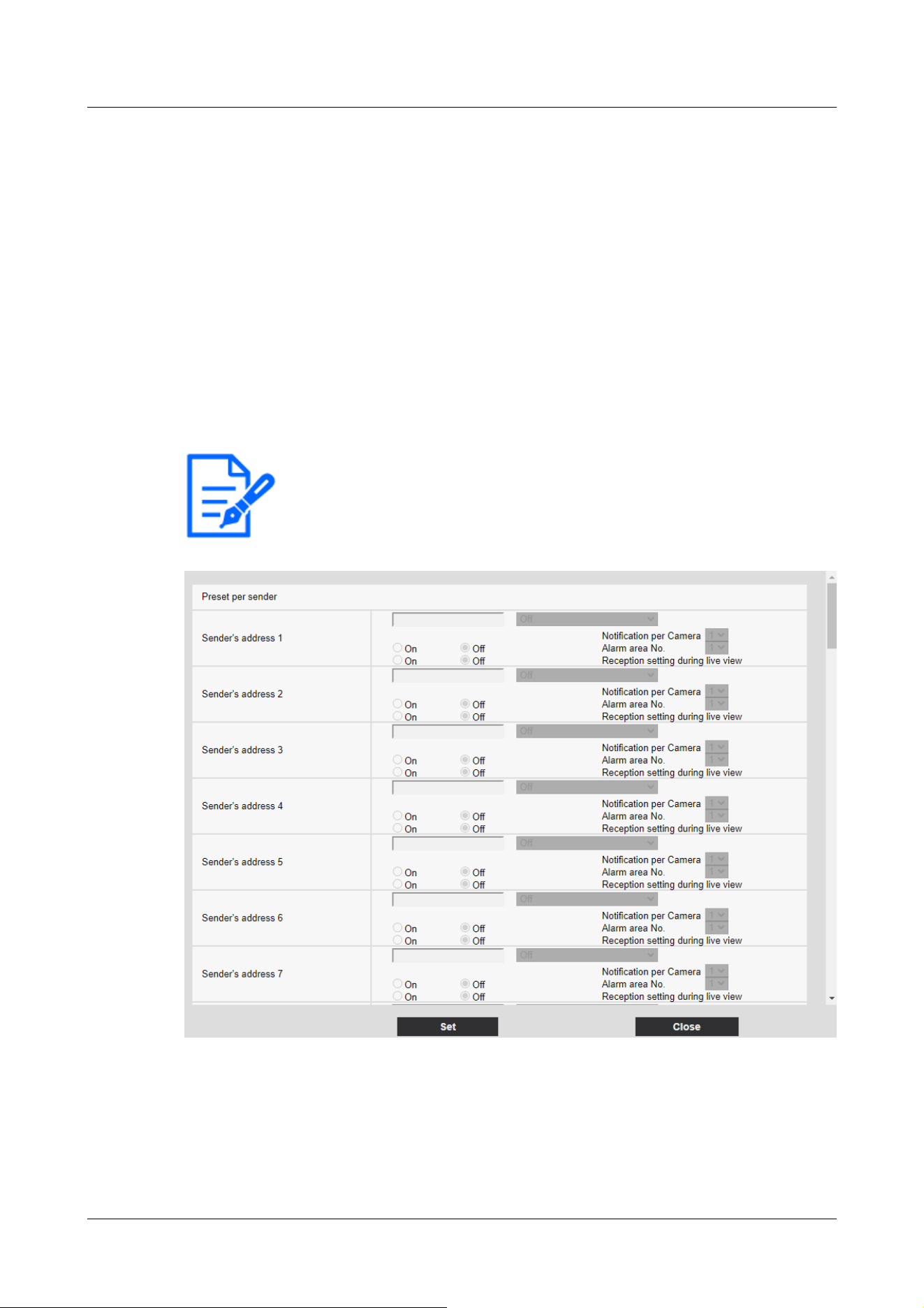
[Note:]
・The items that can be set differ depending on the function of the model.
・Refer to the catalog specifications for the functions installed in each model.
generated is displayed in a separate window.
→14.4.7 Set SNMP transmission when an alarm is generated.
14.4.1 Set the preset position by source (screen for setting preset position by
source)
On the [Alarm] tab of the Alarm page, press [Preset per sender >>] in [Command alarm].
→14.1 [Alarm] to set alarm operation
Here, the address of the source of the command alarm and the preset position corresponding to
that address are registered.
AI Outdoor IR Bullet Camera
14 [Alarm] to set the alarm
14.4 [Alarm] to set alarm linkage operation
436
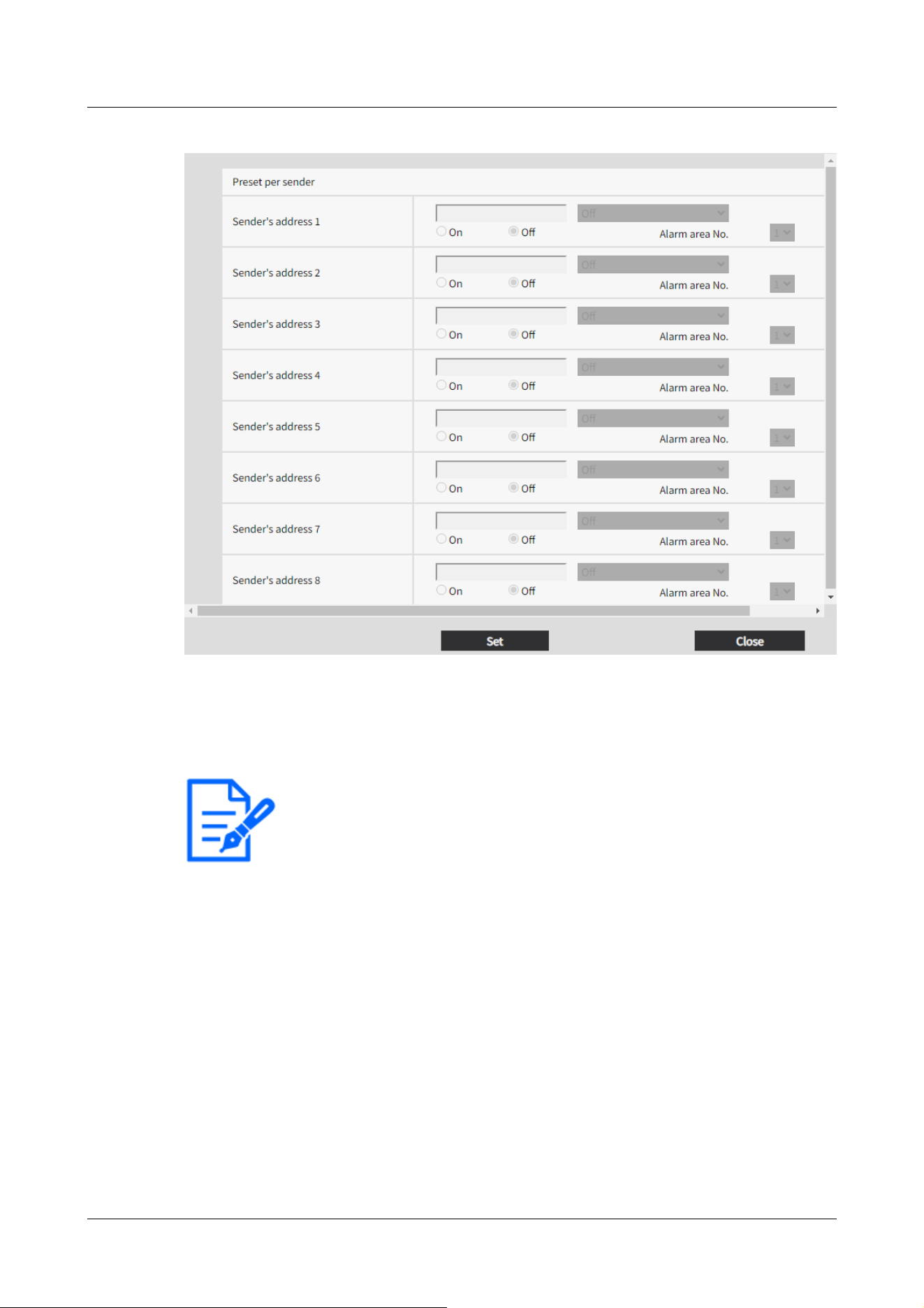
[Note:]
・[AI Outdoor IR Bullet] Source Address can be set from [Sender's address 1] to
[Sender's address 8].
[Sender's address 1] through [Sender's address 48]
Set the IP address of the sender of the command alarm and the preset position to move
corresponding to the IP address. You can set up to 48 notifications.
[Notification per Camera]
If the transmission source is a Multi-directional camera, select the camera number of the
transmission source. Otherwise, select [1].
[On]/[Off] (Alarm area no. interlock)
Use [On]/[Off] to set whether or not to link with [Alarm area No.].
[Alarm area No.]
When [Alarm Area No. Interlock] is set, select the sender alarm area No. from 1 to 8.
14 [Alarm] to set the alarm
14.4 [Alarm] to set alarm linkage operation
437

[Note:]
・Only models with FTP/SFTP functions can be set.
・The factors displayed differ depending on the function of the model.
・Refer to the catalog specifications for the functions installed in each model.
[On]/[Off] (Reception setting during live view)
On/Off is used to select whether to link with the clicking operation of the live image of the
Multi-directional camera.
[Close] buttons
Click this button to close the Source-Specific Preset Position window.
14.4.2 Mail sending when an alarm is generated
On the [Alarm] tab of the Alarm page, press [E-mail notification setup] in [Camera action on
alarm].
→14.1 [Alarm] to set alarm operation
Refer to the following for the setting method.
→16.2.1 Set mail sending
14.4.3 Set up FTP/SFTP transmission when an alarm is generated
On the [Alarm] tab of the Alarm page, press [FTP/SFTP setup] in [Camera action on alarm].
→14.1 [Alarm] to set alarm operation
Refer to the following for the setting method.
→16.2.2 Configuring FTP/SFTP transmission function
14 [Alarm] to set the alarm
14.4 [Alarm] to set alarm linkage operation
438
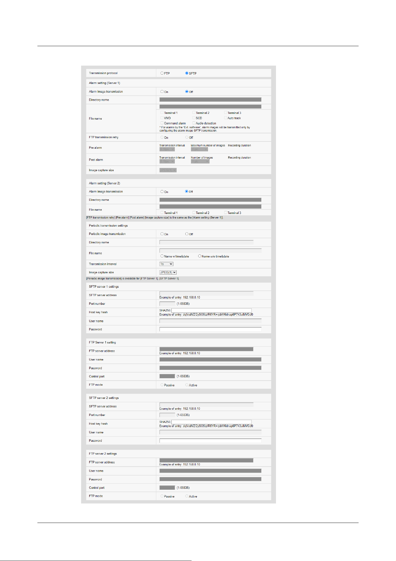
14 [Alarm] to set the alarm
14.4 [Alarm] to set alarm linkage operation
439

14.4.4 Sets recording data to SD Memory Card when alarm is generated.
On the [Alarm] tab of the Alarm page, press [SD memory card setup] in [Camera action on alarm].
→14.1 [Alarm] to set alarm operation
Refer to the following for the setting method.
→9.2 [SD memory card] for setting SD Memory Cards
14.4.5 Sets unique alarm notification when an alarm is generated.
On the [Alarm] tab of the Alarm page, press [TCP alarm notification setup] in [Camera action on
alarm].
→14.1 [Alarm] to set alarm operation
Refer to the following for the setting method.
→14.12.1 Set unique alarm notification
14.4.6 Sets HTTP alarm notification when an alarm is generated.
On the [Alarm] tab of the Alarm page, press [HTTP alarm notification setup] in [Camera action on
alarm].
→14.1 [Alarm] to set alarm operation
Refer to the following for the setting method.
→14.12.2 Set the HTTP alarm notification
14.4.7 Set SNMP transmission when an alarm is generated.
On the [Alarm] tab of the Alarm page, press [To SNMP setting] in [Camera action on alarm].
→14.1 [Alarm] to set alarm operation
Refer to the following for the setting method.
→16.2.7 Set SNMP
14.5 [VMD area] for setting motion detection
Click [VMD area] on the Alarm page. Refer to the following how to display and operate the
Advanced menu.
→5.1 How to display
14 [Alarm] to set the alarm
14.5 [VMD area] for setting motion detection
440

[Note:]
・[PTZ] Up to four areas can be set for each preset position (up to 256).
・[PTZ] You can also set the alarm operation when the camera is at a position other
than the preset position.
・[MULTI] [Compact] Up to four areas can be set for each camera.
・[New X Fixed-8MP][New X Fixed-6MP][New X Fixed-5MP][AI Outdoor IR
BulletX-8M][AI Outdoor IR BulletX-5M]If [Image capture mode] is set to [60fps
Mode] or [50fps Mode], [VMD] cannot be used.
[Important]
・When the motion detector function is used to detect the movement of an object,
[Alarm notification] is displayed for confirmation.
→2.3.2 About live image pages
・[Alarm notification] is also displayed when the alarm input is received with the
terminal alarm or when the command alarm is received.
・Depending on the network environment, notification may be delayed.
・If the [Image capture mode] of the [Basic] tabs is changed after the VMD area is
set, the VMD area may be misaligned. Be sure to check the setting of the motion
detection area again.
・When [Intelligent Auto] is set to [On], the VMD alarm may be generated because
the brightness of the entire image changes depending on the subject's condition.
In this case, set one of the following settings.
-Set [Illumination detection suppression] to [On] for motion detection.
-Adjust the slider bar of the [Detection sensitivity] in the motion detection area
to the [Low] direction.
Adjust the [Face priority level (Brightness)] slider bar of the intelligent auto to
[-].
・The motion detector function is not intended to prevent theft, fire, etc. We will
not be liable for any accident or damage.
→5.2 How to operate
Here, the area for detecting the movement of an object using the motion detector function is set.
An alarm is activated when the movement of an object in the set area is detected.
Position Selection and Information Addition Setting Screen
14 [Alarm] to set the alarm
14.5 [VMD area] for setting motion detection
441
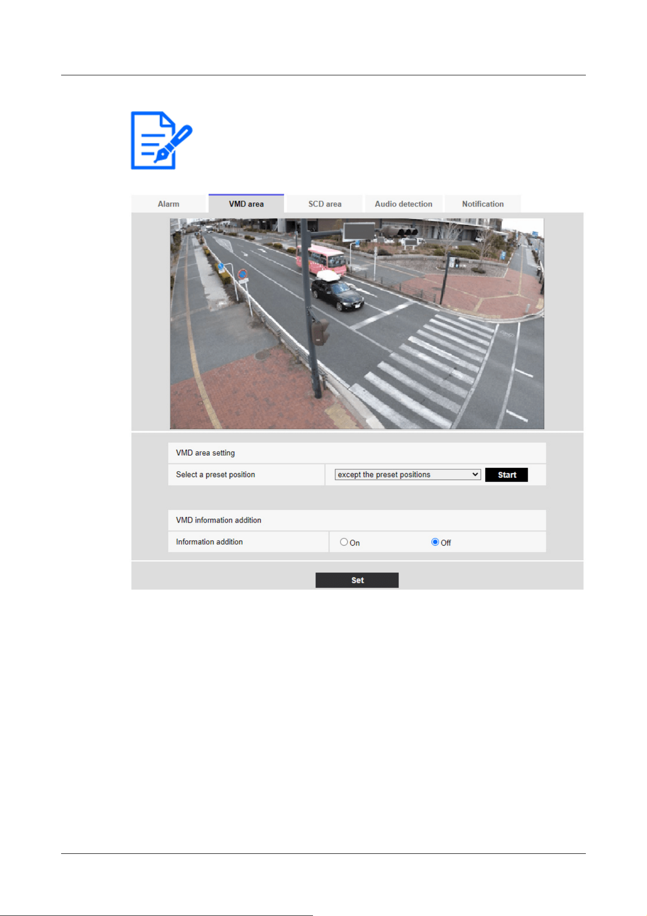
[Note:]
・[PTZ][AI Outdoor IR Bullet]Only the PTZ camera and AI Outdoor IR Bullet
Camera can be set for position selection and information addition setting screen.
VMD area setting
[Select a preset position]
Select the preset position number for which the motion detection area is to be set and press
[Start] to set the motion detection area.
Select [except the preset positions] to set the VMD area other than the preset position.
VMD information addition
[Information addition]
Sets whether to send the superimposed image data by [On] or [Off] by adding motion detection
14 [Alarm] to set the alarm
14.5 [VMD area] for setting motion detection
442
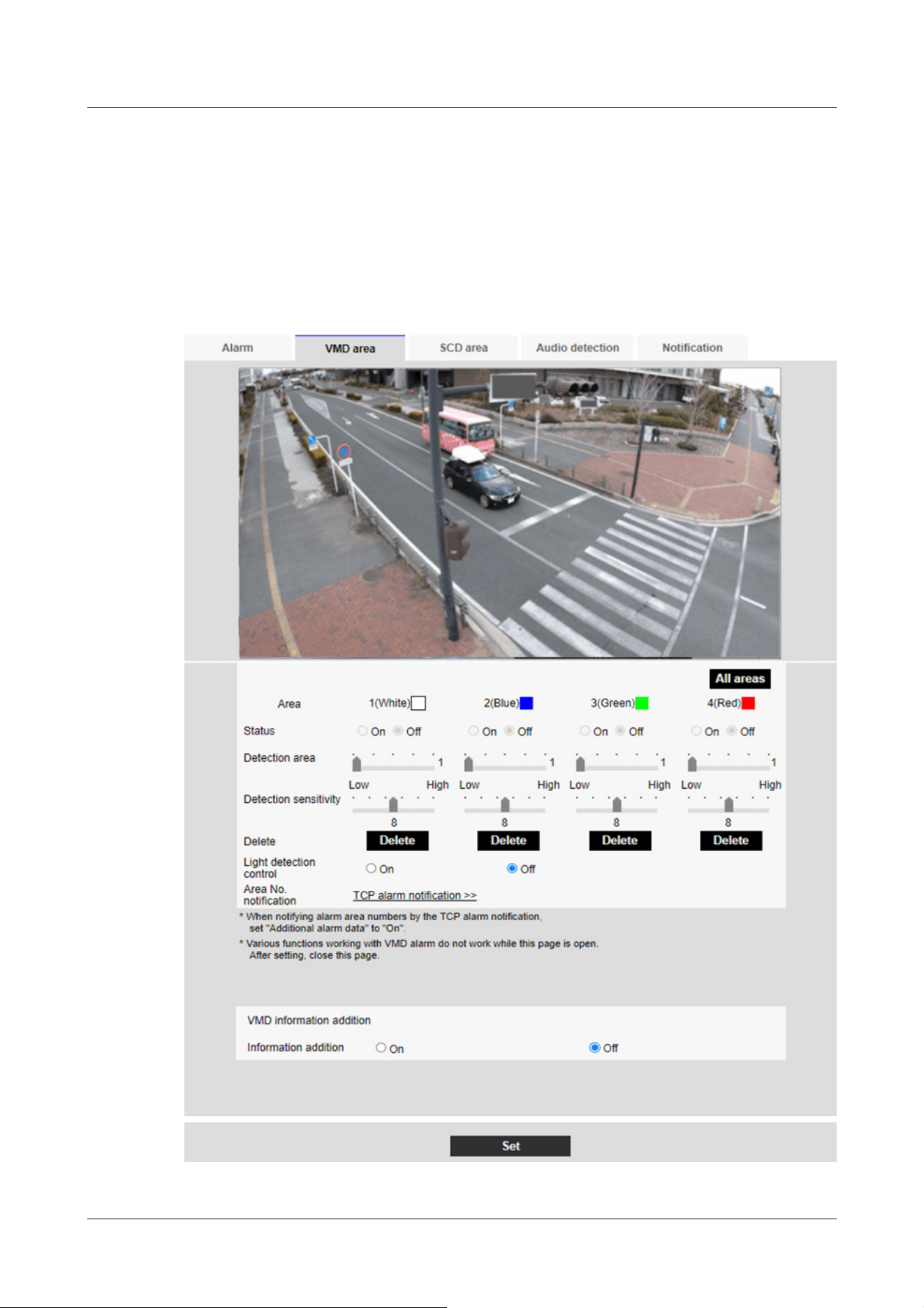
data to the image.
The operation detection information can be used by some of the search functions of the network
disk recorder manufactured by us.
For details of the functions and settings, refer to the instruction manual of the connected device.
VMD area setting screen
Compact Dome cameras, New X Fixed Cameras, U-series camera with edge AI
14 [Alarm] to set the alarm
14.5 [VMD area] for setting motion detection
443
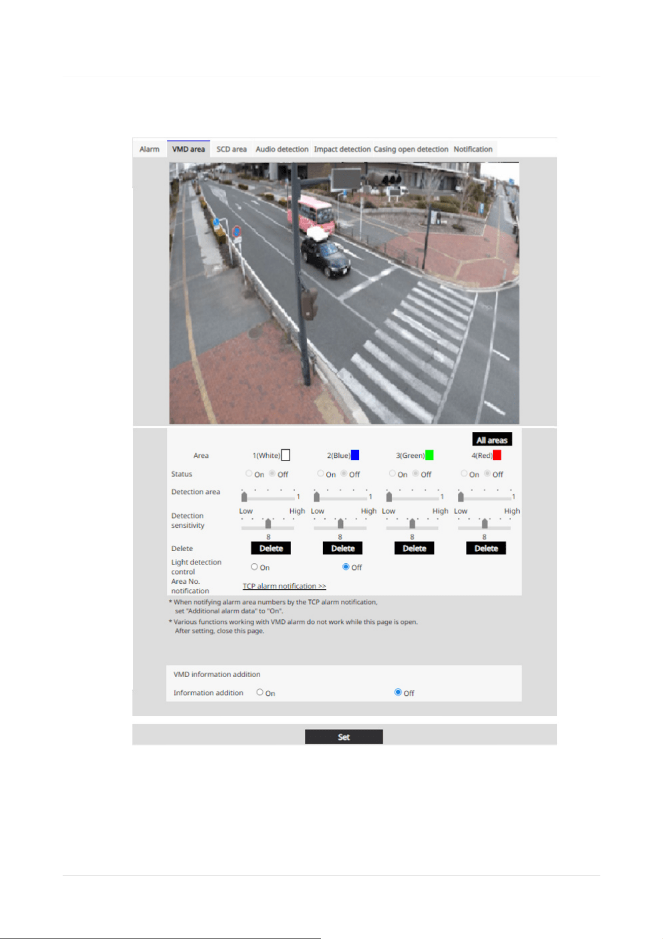
Corner cameras
[Area]
When the motion detection area is selected in the image, it is set in order from Area 1.
[All areas] buttons
14 [Alarm] to set the alarm
14.5 [VMD area] for setting motion detection
444

[Important]
・If the lighting intensity is small, it may be impossible to suppress it.
・When the illumination detection suppression is set to [On] and a object
movement is detected throughout the window, operation detection may not be
performed.
・If [Camera title on screen display] is set to [On], the accuracy of motion
detection may be reduced.
Clicking this button selects the entire area as the motion detection area and sets it to the
[1(White)] of [Area].
[Status]
Enable/disable operation detection.
[Enable:Operation detection is performed.
[Disabled:Operation detection is not performed.
[Detection area]
Set the area for detecting movement of object in the motion detection area with the slider bar.
The smaller the set value, the smaller the object movement will be detected. The current setting
(1 to 10) is displayed to the right of the slider bar.
[Detection sensitivity]
Use the slider bar to set the sensitivity for detecting movement in the area. Individual settings can
be made for each area. The larger the set value, the easier it is to sense the movement.
The current setting (1 (Low) to 15 (High)) is displayed under the slider bar.
[Delete] buttons
Click the area button to delete the area frame.
[Light detection control]
Use the [On] and [Off] buttons to specify whether or not the operation is not detected due to
changes in the illumination.
[Area No. notification]
Clicking [TCP alarm notification setup >>] displays the [Transmission] tabs on the Alarm Page.
→14.1 [Alarm] to set alarm operation
Addition of motion detection information
14 [Alarm] to set the alarm
14.5 [VMD area] for setting motion detection
445
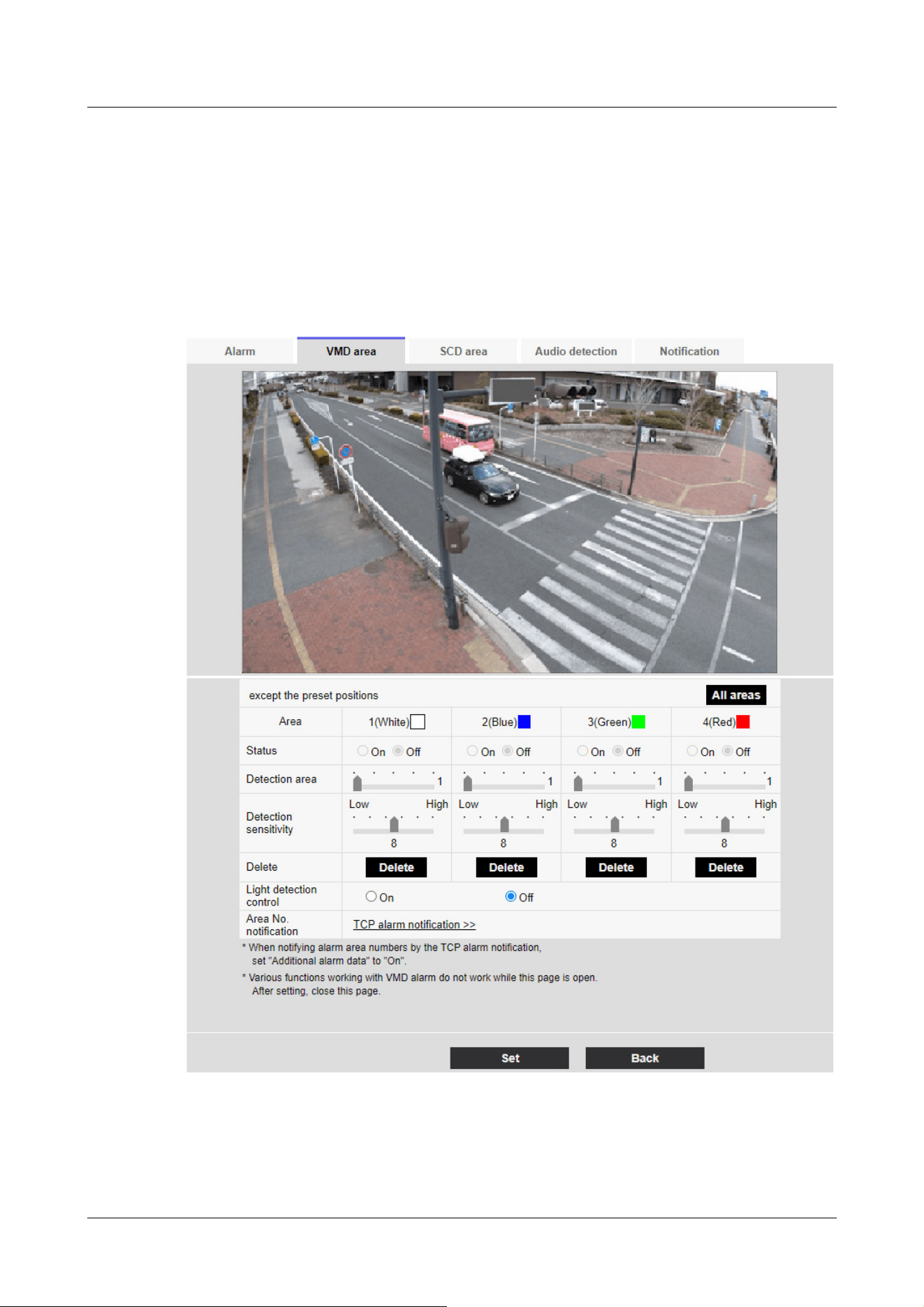
[Information addition]
Adds motion detection information to images and sets on/off whether to transmit superimposed
image data. The operation detection information can be used by some of the search functions of
the network disk recorder manufactured by us. For details of the functions and settings, refer to
the instruction manual of the connected device.
PTZ camera, AI Outdoor IR Bullet Camera
[Area]
When the motion detection area is selected in the image, it is set in order from Area 1.
14 [Alarm] to set the alarm
14.5 [VMD area] for setting motion detection
446

[Important]
・If the lighting intensity is small, it may be impossible to suppress it.
・When the illumination detection suppression is set to [On] and the subject with
movement throughout the screen is detected, the operation detection may not be
performed.
[All areas] buttons
Clicking this button selects the entire area as the motion detection area and sets it to the
[1(White)] of [Area].
[Status]
Enable/disable operation detection.
[On]:Operation detection is performed.
[Off]:Operation detection is not performed.
[Detection area]
Set the area of the slider bar to detect movement of the subject in the motion detection area. The
smaller the set value, the smaller the movement of the subject is detected. The current setting (1
to 10) is displayed to the right of the slider bar.
[Detection sensitivity]
Use the slider bar to set the sensitivity for detecting movement in the area. Individual settings can
be made for each area. The larger the set value, the easier it is to sense the movement.
The current setting (1 (Low) to 15 (High)) is displayed under the slider bar.
[Delete] buttons
Click the area button to delete the area frame.
[Light detection control]
Use the [On] and [Off] buttons to specify whether or not the operation is not detected due to
changes in the illumination.
[Area No. notification]
Clicking [TCP alarm notification setup] displays the [Notification] tabs on the Alarm Page.
→14.1 [Alarm] to set alarm operation
Addition of motion detection information
[Information addition]
14 [Alarm] to set the alarm
14.5 [VMD area] for setting motion detection
447
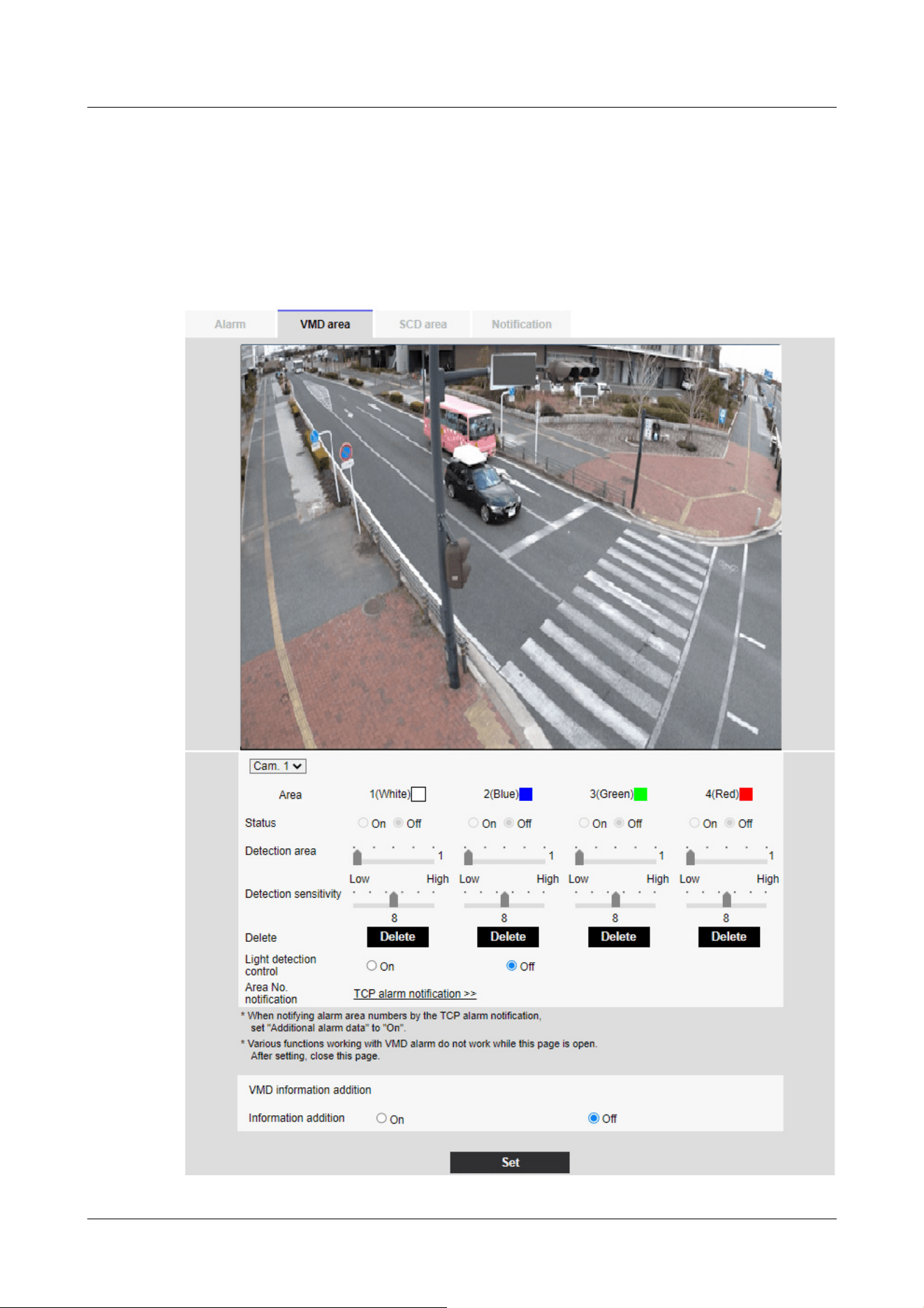
Adds motion detection information to images and sets on/off whether to transmit superimposed
image data. The operation detection information can be used by some of the search functions of
the network disk recorder manufactured by us. For details of the functions and settings, refer to
the instruction manual of the connected device.
Multi-directional camera
14 [Alarm] to set the alarm
14.5 [VMD area] for setting motion detection
448

[Important]
・If the lighting intensity is small, it may be impossible to suppress it.
・When the illumination detection suppression is set to [On] and the subject with
movement throughout the screen is detected, the operation detection may not be
performed.
[Camera selection]
Select the camera to set the area from each camera.
[Area]
When the motion detection area is selected in the image, it is set in order from Area 1.
[Status]
Enable/disable operation detection.
[On]:Operation detection is performed.
[Off]:Operation detection is not performed.
[Detection area]
Set the area of the slider bar to detect movement of the subject in the motion detection area. The
smaller the set value, the smaller the movement of the subject is detected. The current setting (1
to 10) is displayed to the right of the slider bar.
[Detection sensitivity]
Use the slider bar to set the sensitivity for detecting movement in the area. Individual settings can
be made for each area. The larger the set value, the easier it is to sense the movement.
The current setting (1 (Low) to 15 (High)) is displayed under the slider bar.
[Delete] buttons
Click the area button to delete the area frame.
[Light detection control]
Use the [On] and [Off] buttons to specify whether or not the operation is not detected due to
changes in the illumination.
[Area No. notification]
Clicking [TCP alarm notification setup] displays the [Notification] tabs on the Alarm Page.
→14.1 [Alarm] to set alarm operation
14 [Alarm] to set the alarm
14.5 [VMD area] for setting motion detection
449

[Important]
・All alarms are not detected while the setting is being changed on the setting
screen. Close the setting screen after setting is completed.
Addition of motion detection information
[Information addition]
Sets whether to send the superimposed image data by [On] or [Off] by adding motion detection
data to the image. The operation detection information can be used by some of the search
functions of the network disk recorder manufactured by us. For details of the functions and
settings, refer to the instruction manual of the connected device.
14.6 [VMD area] to set the motion detection area
Set the motion detection area.
1 When you drag the mouse on the image and specify an area, the specified area is set to Area
[1(White)] and a frame is displayed.
Areas are set from the first to the first area number. The color next to the area number
indicates the corresponding color of the frame. In addition, the frame [Status] to be set for
the area becomes [On].
14 [Alarm] to set the alarm
14.6 [VMD area] to set the motion detection area
450
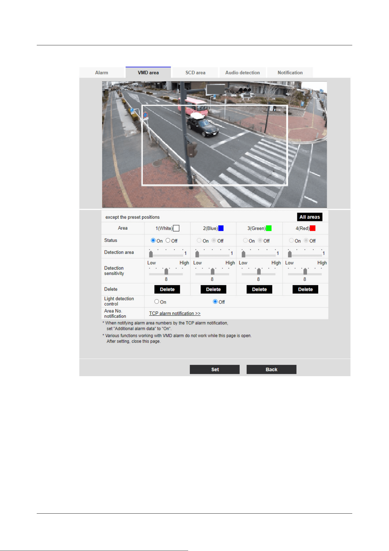
2 Set the [Detection area] [Detection sensitivity] with the slider bar. For [Detection area]
[Detection sensitivity], see the following.
→14.5 [VMD area] for setting motion detection
The area displayed and the movement detection status at the detection sensitivity are
displayed in [Detection area]. Modify areas and [Detection area] [Detection sensitivity] as
required.
3 When you are finished, press [Set].
14 [Alarm] to set the alarm
14.6 [VMD area] to set the motion detection area
451

[Important]
・If you do not press the [Set] buttons, the settings will not be confirmed.
[Note:]
・[New X Fixed-8MP][New X Fixed-6MP][New X Fixed-5MP][AI Outdoor IR
BulletX-8M][AI Outdoor IR BulletX-5M]If [Image capture mode] is set to [60fps
Mode] or [50fps Mode], [SCD] cannot be used.
[Important]
・In the following cases, the undesired signal detection function will not work for a
while.
After turning on the power
-after changing the undesired detection setting
-when the image angle of the machine changes
・When a disturbance is detected using the disturbance detection function, [Alarm
notification] is displayed for confirmation.
→2.3.2 About live image pages
・[Alarm notification] is also displayed when an alarm input is received with a
terminal alarm or other alarm such as an operation detection alarm is generated.
4 To disable the motion detection area, change the [Status] of the area in question to [Off] and
click [Set]. The disabled box will be dotted.
When disabled, no alarm is generated even if there is a change in the area.
5 To delete an area for motion detection, click [Delete] in the area to delete to delete the area
frame.
6 When [Set] is clicked, the settings are reflected in the computer.
14.7 [SCD area] to set up undesired detection
This section sets the disturbance detection function.
The jamming detection function activates an alarm when the camera detects a change in the
subject by covering the camera with a cloth or a lid or changing the orientation of the camera
significantly. You can set up one area. When disturbance is detected in the set area, an alarm is
activated.
14 [Alarm] to set the alarm
14.7 [SCD area] to set up undesired detection
452

・If you configure the disturbance detection area and then change the [Image
rotation] or [Image] tab [Image capture mode] on the [Basic] tab, the disturbance
detection area may shift. Be sure to reconfirm the settings of the disturbance
detection area.
・Set [Detection Time] of the disturbance detection function shorter than [Dwell
time] of black and white switching.Alarm is detected in performance even when
the brightness changes suddenly, such as when the lighting is switched.
・In the following cases, disturbance detection may not be detected or may be
erroneously detected.
-If only part of the screen is covered or transparent
-when the camera is oriented in a similar manner before and after the camera
-if a privacy zone is set
・When the color of the image is close to monochrome, it is difficult to detect
disturbance. If undesired detection is difficult, increase the [Detection sensitivity]
setting of the undesired detection function or increase the area of the undesired
detection function.
・When [Intelligent Auto] is set to [On], the undesired detection alarm may be
generated because the brightness of the entire image changes depending on the
subject's condition. In this case, set one of the following settings.
-Set [Detection sensitivity] to a low setting.
-Set [Detection Time] for a long time.
-Adjust the [Face priority level (Brightness)] slider bar of the intelligent auto to
[-].
・The disturbance detection function is not used to prevent theft, fire, etc. We will
not be liable for any accident or damage.
[Note:]
・[MULTI] [Camera selection] can be selected only for Multi-directional cameras.
[Camera selection]
Select the camera to set the area from each camera.
[Area]
Set the disturbance detection area in the image.
[All areas]
14 [Alarm] to set the alarm
14.7 [SCD area] to set up undesired detection
453

[Note:]
・Additional disturbance detection information is not used by our network disk
recorders (as of April 2022).
[Important]
・All alarms are not detected while the setting is being changed on the setting
screen. Close the setting screen after setting is completed.
Click this button to set the entire area as a disturbance detection area.
[Status]
Use the [On] and [Off] buttons to specify whether or not to perform undesired detection.
[On]: Detects disturbance.
[Off]: No disturbance detection is performed.
[Detection area]
Set the area for detecting movement of the subject in the disturbance detection area to [Small],
[Middle] and [Large].
[Detection sensitivity]
The sensitivities for detection of disturbance in the area are set from [Very Low], [Low], [Middle],
and [High].
[Detection Time]
Sets the time from when the subject changes to when the disturbance detection alarm is activated.
The alarm does not operate when the subject changes only within the set time.
[3s]/ [5s]/ [10s]/ [30s]/ [1min]
[Delete] buttons
Click to delete the area frame.
Addition of undesired detection information
[Information addition]
Set [On] and [Off] to send superimposed image data by adding undesired detection data to the
image.
14.8 [SCD area] to set up SCD area
Set the disturbance detection area.
14 [Alarm] to set the alarm
14.8 [SCD area] to set up SCD area
454
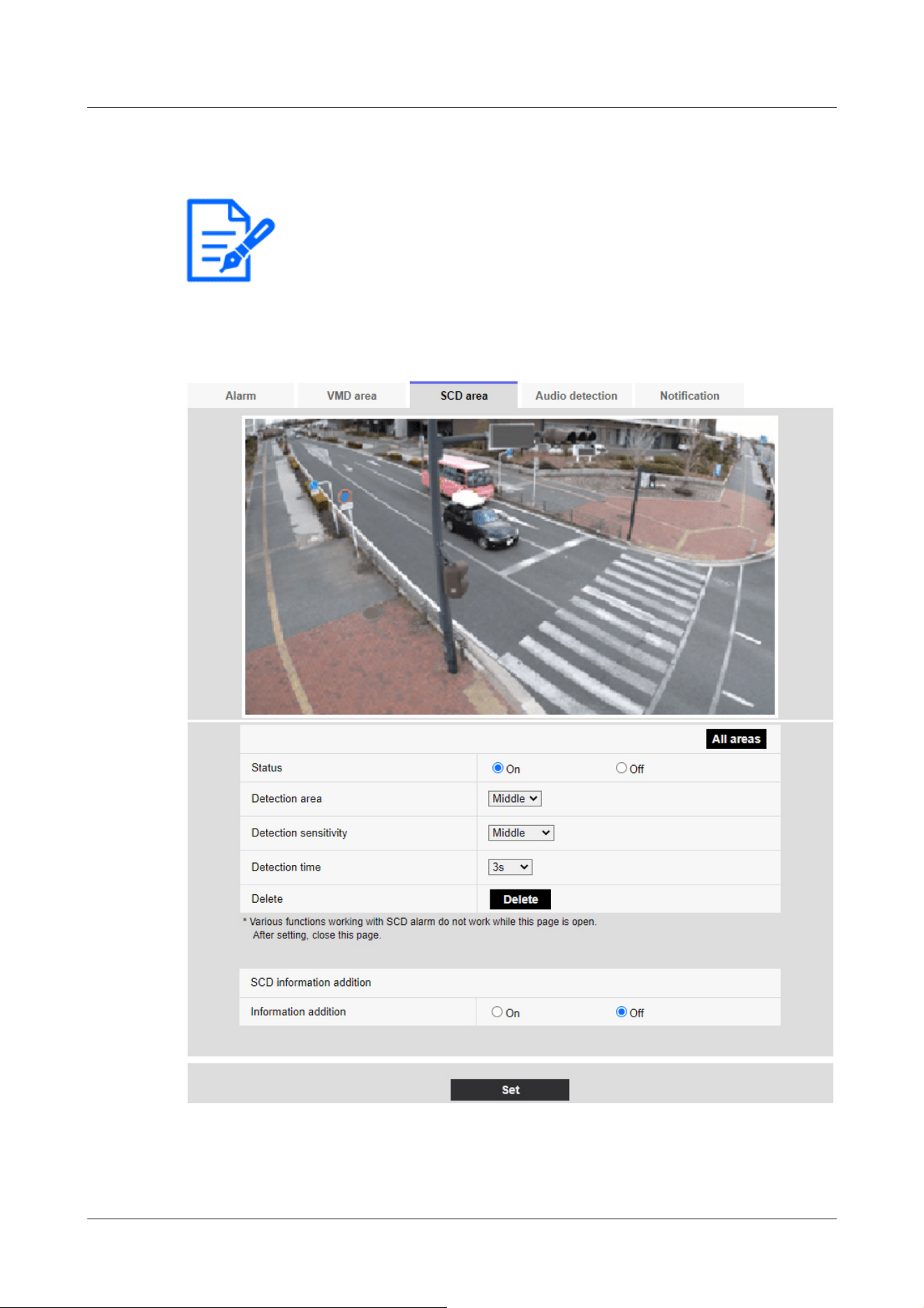
[Note:]
・[MULTI] [Camera selection] can be selected only for Multi-directional cameras.
1 Select the camera from which the area is to be set by [Camera selection].
2 Clicking [All areas] selects the entire area as the disturbance detection area and displays a
frame around the entire screen. Also, [Status] is set to [On].
When you drag the mouse on the image and specify an area, the specified area is set to the
area (white) and a frame is displayed. In addition, [Status] becomes [On].
14 [Alarm] to set the alarm
14.8 [SCD area] to set up SCD area
455
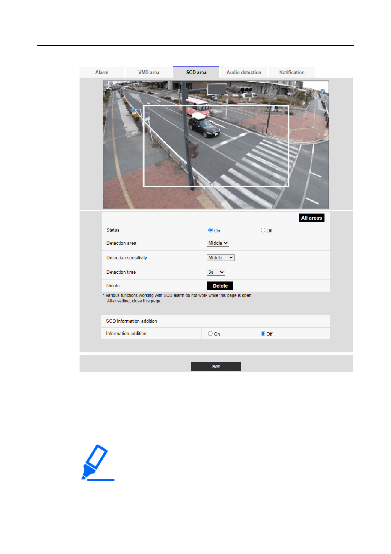
[Important]
・If you do not press the [Set] buttons, the settings will not be confirmed.
3 Set [Detection area] [Detection sensitivity] [Discovery Time]. For [Detection area]
[Detection sensitivity], refer to the following.
→14.7 [SCD area] to set up undesired detection
Change the area or [Detection area] [Detection sensitivity] as required.
4 When you have finished setting, press [Set].
14 [Alarm] to set the alarm
14.8 [SCD area] to set up SCD area
456

[Note:]
・If you want to reconfigure the disturbance detection area, you must clear the
area frame by clicking [Delete] button.
[Note:]
・[New X Fixed-8MP][New X Fixed-5MP][AI Outdoor IR BulletX-8M][AI Outdoor
IR BulletX-5M] If [Image capture mode] is set to [60fps Mode] or [50fps Mode],
[Audio detection] cannot be used.
[Important]
・When the sound detection function is used to detect sound, [Alarm generation
notification] is displayed so that the sound detection is confirmed.
・[Alarm notification] is also displayed when the alarm input is received with the
terminal alarm or when the command alarm is received.
・Depending on the network environment, notification may be delayed.
・The sound detection function is not suitable for applications that require high
reliability at all times (systems designed to prevent problems). We will not be
liable for any accident or damage.
5 To disable the disturbance detection area, change [Status] to [Off] and press [Set]. Click this
button to display a dotted line with the disabled frame color. When disabled, no alarm is
generated by undesired disturbance detection.
6 To delete the SCD area, press [Delete]. Click to clear the area frame.
7 When [Set] is clicked, the settings are reflected in the computer.
14.9 [Audio detection] for setting sound detection
Click [Audio detection] on the Alarm page. Refer to the following how to display and operate the
Advanced menu.
→5.1 How to display
→5.2 How to operate
Here, the sound detection setting is performed.
14 [Alarm] to set the alarm
14.9 [Audio detection] for setting sound detection
457
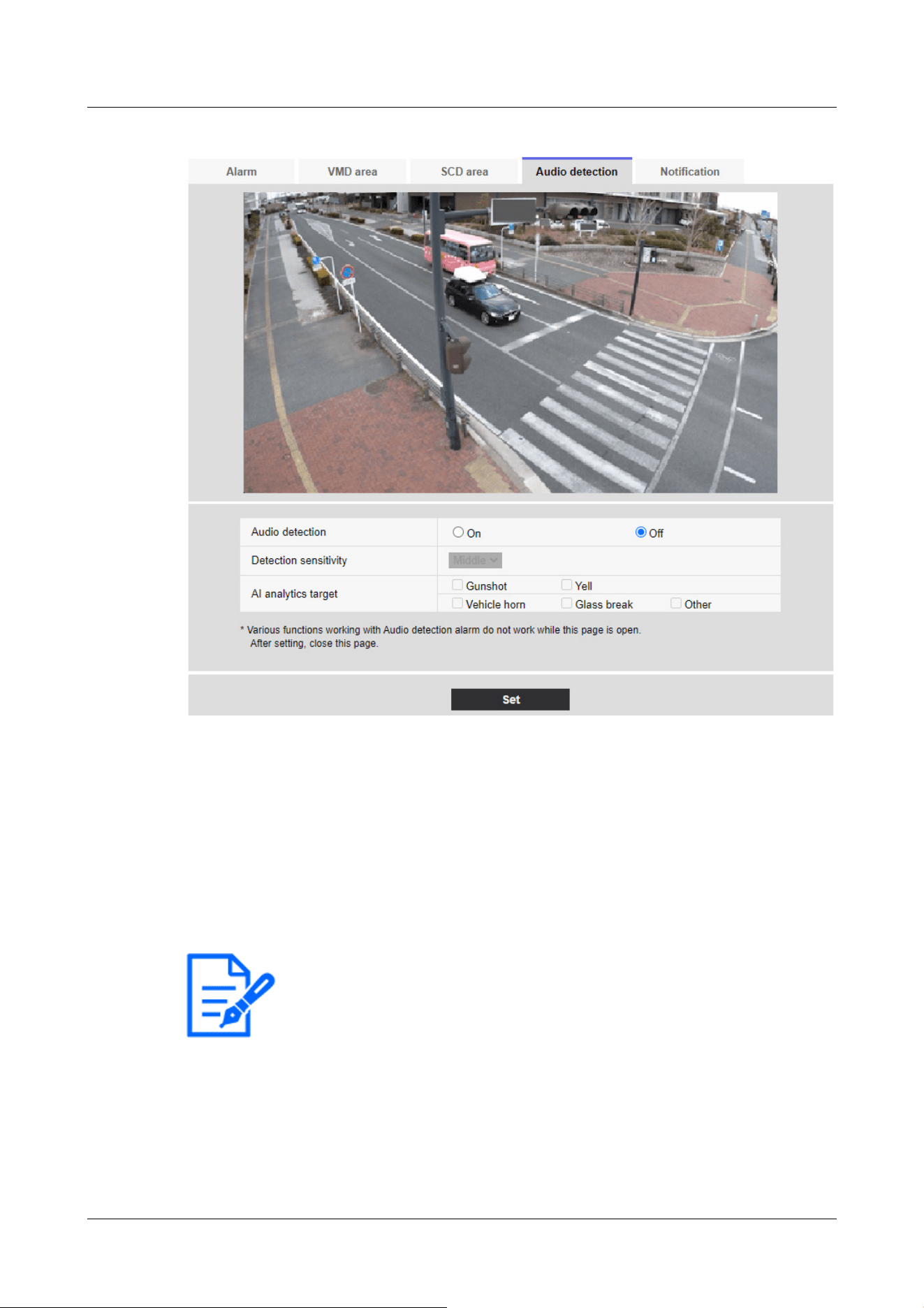
[Note:]
・When installing cameras indoors, it is recommended that [Sense Level] be set to
[Low].
[Audio detection]
ON/OFF is used to specify whether or not to perform sound detection.
[On]:Sound detection is performed.
[Off]:Sound detection is not performed.
[Detection sensitivity]
Select the sensitivity of detection from the [Low] [Middle] [High].
[AI analytics target]
Select the target for detecting AI tone identification.
• [Gunshot]: Detects gunshot, explosive, shock and bursting sounds.
• [Yell]: It detects human screams and crys.
14 [Alarm] to set the alarm
14.9 [Audio detection] for setting sound detection
458

[Note:]
・In the following cases, the target sound may not be detected.
-if the duration of the cry/horn/glass break is shorter than 1 second
When the difference between the noise of interest and ambient noise is less than 6
dB
If the rain hits the camera microphone directly
・When multiple types of target sounds are generated at the same time, only one
type of alarm is notified.
・The message ID of the unique alarm notification for AI sound identification is as
follows.
Used for registering sound identification alarms with a recorder or our video
monitoring software.
BOOK: 70
--a broken glass: 71
-horn: 72
--shriek: 73
Other: 55
・When an alarm notification for AI sound identification is received by a recorder,
etc., the alarm cannot be received by a recorder etc. during the alarm mask
period.
• [Vehicle horn]: Detects the horn of the car.
• [Glass break]: Detects the cracking of windows.
[Other]: Detects other sounds than gunshot, screech, horn, or cracking of glasses.
14.10 [Impact detection] for setting impact detection
Click [Impact detection] on the Alarm page. Refer to the following how to display and operate the
Advanced menu.
→5.1 How to display
→5.2 How to operate
Here, the impact detection setting is performed.
14 [Alarm] to set the alarm
14.10 [Impact detection] for setting impact detection
459

[Note:]
・[Corner] Impact detection can be set only for Corner cameras.
[Important]
・When the impact detection function is used to detect impact, [Alarm generation
notification] is displayed so that the impact detection is confirmed.
・All alarms are not detected while changing settings on the setting screen. Close
the setting screen after completing the setting.
・[Alarm notification] is also displayed when the alarm input is received with the
terminal alarm or when the command alarm is received.
・Depending on the network environment, notification may be delayed.
・The impact detection function is not suitable for applications that require high
reliability at all times (systems designed to prevent problems). We will not be
liable for any accident or damage.
14 [Alarm] to set the alarm
14.10 [Impact detection] for setting impact detection
460
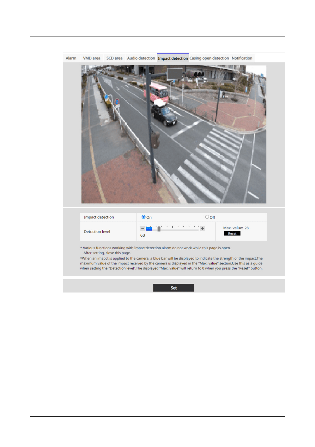
[Impact detection]
Use On/Off to set whether or not to perform impact detection.
[On]:Performs impact detection.
[Off]:Does not perform impact detection.
[Detection level]
Use the slider bar to set the threshold at which the impact is detected.
You can adjust the value from 1 to 255. Moving in the [+] direction weakens the sensitivity for
detecting shocks, allowing you to detect only large shocks. [-] When it is moved in the direction,
the sensitivity to detect the impact becomes stronger, and even small impacts can be detected.
14 [Alarm] to set the alarm
14.10 [Impact detection] for setting impact detection
461

[Note:]
・When an impact is applied to the camera while [Impact detection] is set to [On],
a blue bar indicating the impact intensity is displayed. The maximum impact
received by the camera is displayed in the [Max.value:]. Use this as a guide when
setting the [Detection level]. Press [Reset] to return to 0 for [Max.value:] displayed.
[Note:]
・[Corner] Opening detection can be set only for Corner cameras.
[Important]
・When the opening detection function is used to detect opening, [Alarm
generation notification] is displayed so that the opening detection is confirmed.
・All alarms are not detected while changing settings on the setting screen. Close
the setting screen after completing the setting.
・[Alarm notification] is also displayed when the alarm input is received with the
terminal alarm or when the command alarm is received.
・Depending on the network environment, notification may be delayed.
・The opening detection function is not suitable for applications that require high
reliability at all times (systems designed to prevent problems). We will not be
liable for any accident or damage.
14.11 [Casing open detection] for setting opening detection
Click [Casing open detection] on the Alarm page. Refer to the following how to display and
operate the Advanced menu.
→5.1 How to display
→5.2 How to operate
Here, the opening detection setting is performed.
14 [Alarm] to set the alarm
14.11 [Casing open detection] for setting opening detection
462
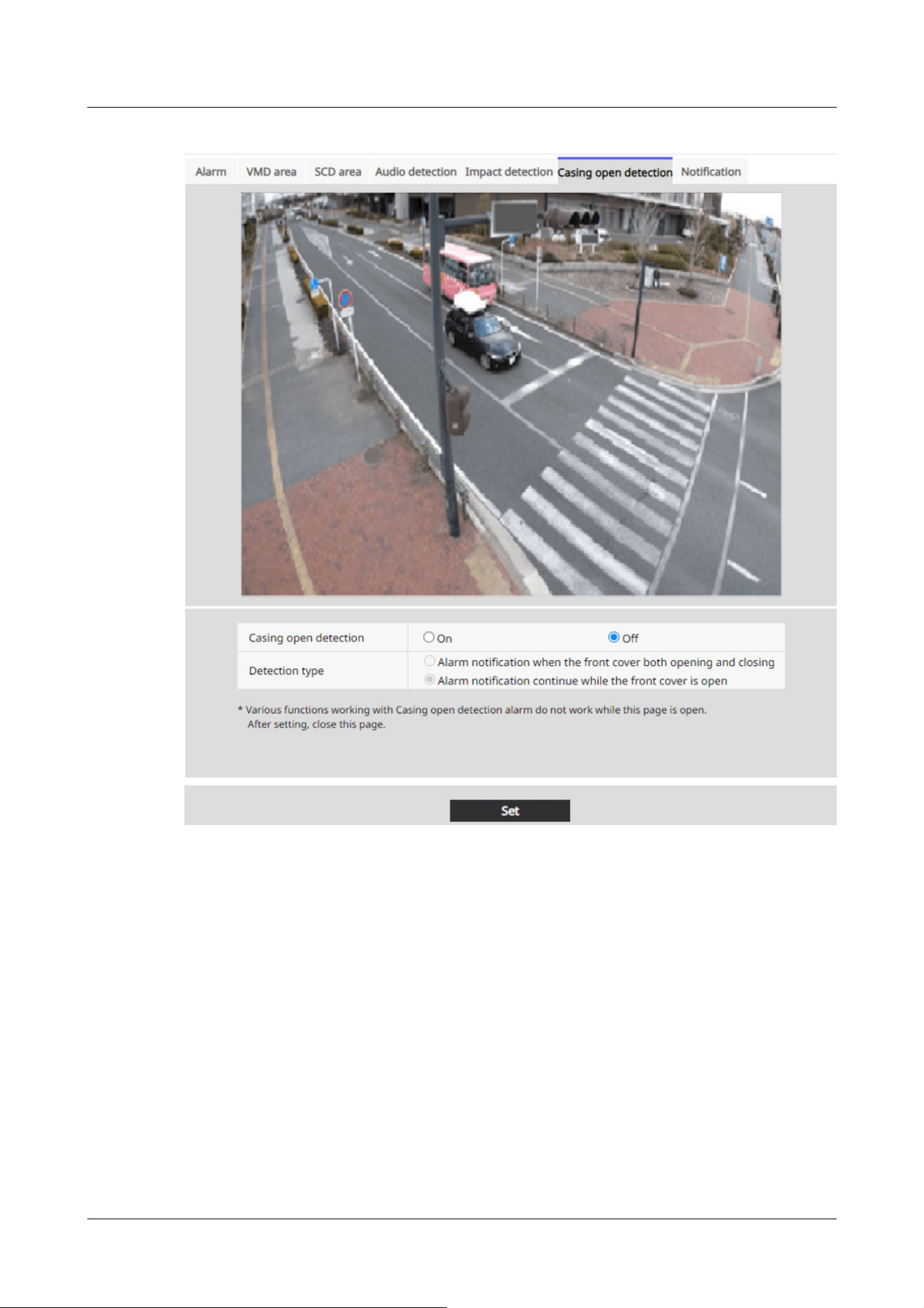
[Casing open detection]
Use On/Off to set whether or not to perform opening detection.
[On]:Performs opening detection.
[Off]:Does not perform opening detection.
[Detection type]
Select an action to notify an alarm.
[Alarm notification when the front cover both opening and closing]:Notifies you of an alarm when
the camera front cover is opened and closed.
[Alarm notification continue while the front cover is open]:Alarm continues while the front cover
of the camera is open.
14 [Alarm] to set the alarm
14.11 [Casing open detection] for setting opening detection
463

[Note:]
・If [Alarm notification when the front cover both opening and closing] is selected,
an alarm is notified every time the front cover of the camera is opened or closed
regardless of the interval of the alarm non-detection time.
・If [Alarm notification continue while the front cover is open] is selected, the
alarm is periodically notified at the interval of the alarm non-detection time if the
front cover of the camera is open.
・If you select [Alarm notification continue while the front cover is open], no alarm
notification is given even if the front cover of the camera is closed.
14.12 [Notification] to set alarm notification
Click [Notification] on the Alarm page. Refer to the following how to display and operate the
Advanced menu.
→5.1 How to display
→5.2 How to operate
This is used to set the unique alarm notification and HTTP alarm notification.
14.12.1 Set unique alarm notification
Unique alarm notification
[TCP alarm notification]
ON/OFF is used to specify whether or not to perform unique alarm notification in the following
cases.
・When an alarm is generated (unique alarm notification destination: [Alarm] field)
・When notifying the remaining capacity of the SD Memory Card (unique alarm notifying
destination: [Diag.] field)
・When there is insufficient space on the SD Memory Card (unique alarm notification destination:
[Diag.] field)
・When recognizing an SD Memory Card error (Original alarm notification destination: [Diag.]
field)
・When writing to SD Memory Card is failed (unique alarm notification destination: [Diag.] field)
・Upon expiration of the trial period of the function extension software (original alarm notification
destination: [Diag.] field)
14 [Alarm] to set the alarm
14.12 [Notification] to set alarm notification
464

[Note:]
・Notification of unique alarms is made in the order from [Notify Party 1] (only when
checked in the [Alarm] or [Diag.] field).
[Note:]
・[MULTI] The port numbers 32768 to 49151 cannot be set.
[Note:]
・Only PTZ cameras are displayed for auto-tracking.
[Additional alarm data]
Sets ON/OFF whether the detection area number of the operation detection alarm is notified by
the unique alarm.
[Destination port]
Set the receiving port number of the unique alarm notification destination.
Settable range:1~65535
The following port numbers cannot be set because they are used by this computer.
20、 21、 22、 23、 25、 42、 53、 67、 68、 69、 80 110、 123、 161、 162、 443、 554、 995、
1883、 8883、 10669、 10670、 59000~61000
[Retry times]
Set the number of retries when the unique alarm notification cannot be performed.
Settable range:0~30
Destination of notification
PTZ camera, Fixed cameras
[Address 1] ~ [Address 8]
Set the unique alarm notification destination with IP address or host name. You can set up to 8
notification destinations.
[Alarm] field:When the checkbox is checked, the alarm will be notified.
[Diag.] field:When checked, notification of the remaining capacity of the SD Memory Card, lack of
free space of the SD Memory Card, SD Memory Card recognition error, SD Memory Card write
error, and expiration of the trial period of the function extension software are notified.
[Destination server address] field:Enter the IP address or host name of the notification destination.
14 [Alarm] to set the alarm
14.12 [Notification] to set alarm notification
465

[Important]
・If you want to enter a hostname for [Destination address], you must configure the
DNS on the [Network] tab of the network page.
→16.1 Networking [Network]
・Make sure that the notification destination is set correctly. If the notification
destination does not exist, a proprietary alarm notification delay or transmission
failure may occur.
Input Characters:One-byte alphanumeric and one-byte symbols: . _ ‑
To delete the specified notification destination, press [Delete] for the notification destination to
be deleted.
[Auto track cooperation]
ON/OFF is used to set whether or not automatic tracking linkage is set.
When [Auto track cooperation] is set to [On], alarm notification is executed only when [Alarm
Area No.] matches the [Alarm area] number set for auto-tracking alarm. Alarm notification other
than the automatic tracking alarm is not performed. When using the Auto Tracking Coordination
function, set the alarm area condition in Auto Tracking to [On].
[Alarm area No.]
Settable range:1~4
Multi-directional camera
[Address 1] ~ [Address 48]
Set the unique alarm notification destination with IP address or host name. You can set up to 48
notifications.
[Alarm] field:When the checkbox is checked, the alarm will be notified.
[Diag.] field:When checked, notification of the remaining capacity of the SD Memory Card, lack of
free space of the SD Memory Card, SD Memory Card recognition error, SD Memory Card write
error, and expiration of the trial period of the function extension software are notified.
[Destination server address] field:Enter the IP address or host name of the notification destination.
Input Characters:One-byte alphanumeric and one-byte symbols: . _ ‑
To delete the specified notification destination, press [Delete] for the notification destination to
be deleted.
[Notification per Camera]
ON/OFF is used to specify whether or not to execute the transmission setting by camera.
When [Notification per Camera] is set to [On], [Camera No.] is notified when [Camera No.]
matches the number of the camera that generated the operation detection alarm or when [Camera
No.] matches the camera number of the clicked live display.
14 [Alarm] to set the alarm
14.12 [Notification] to set alarm notification
466

[Note:]
・[MULTI] This item is not displayed when [Image capture mode] is in Quad/Dual
mode.
[Note:]
・[MULTI] This item is not displayed when [Image capture mode] is in Quad/Dual
mode.
[Important]
・If you want to enter a hostname for [Destination address], you must configure the
DNS on the [Network] tab of the network page.
→16.1 Networking [Network]
・Make sure that the notification destination is set correctly. If the notification
destination does not exist, a proprietary alarm notification delay or transmission
failure may occur.
[camera No.]
Settable range: 1 to 4
[Notification per VMD area]
ON/OFF is used to set whether the VMD area-specific transmission is set.
When [Notification per VMD area] is set to [On], alarm notification is executed only when [Alarm
Area No.] matches the [Alarm area] number set for the operation detection alarm. Alarm
notification other than the operation detection alarm is not performed. When using the VMD
area-specific transmission function, set the alarm area status for operation detection to [On].
[Alarm area No.]
Settable range:1~8
14.12.2 Set the HTTP alarm notification
HTTP alarm notification
[Address 1] ~ [Address 5]
Set the IP address or host name of the HTTP server that notifies the HTTP alarm. You can set up
to 5 notification destinations.
Input Characters:One-byte alphanumeric and one-byte symbols: . _ ‑
Example of entry:
14 [Alarm] to set the alarm
14.12 [Notification] to set alarm notification
467

[Note:]
・[MULTI_PTZ] Multi-directional camera with integrated Multi-directional/PTZ
can be set up to Notification Destination 4.
[Note:]
・Basic or Digest authentication is performed by an HTTP server authentication
request.
Http://IP address: port number or http://host name: port number
Https://IP address: port number or https://host name: port number
[Alarm] field
When an alarm is generated, the HTTP alarm notification is executed.
[Diag.] filed
Select this to issue HTTP alarm notifications when the amount of free space remaining on the SD
memory card is running low, when there is not enough free space on the SD memory card, when an
SD memory card recognition error occurs, when an SD memory card write error occurs, and when
the trial period for the function extension software will expire.
[Delete] buttons
When this button is clicked, all notifications, user names, password, notification data, and
Detailed setting set for the item are deleted.
[User name]
Enter the user name that accesses the HTTP server.
Number of characters that can be entered:0 to 63 characters
Characters that cannot be entered:Double-byte and single-byte symbols " & : ; ¥
[Password]
Enter the password to access the HTTP server.
Number of characters that can be entered:0 to 63 characters
Characters that cannot be entered:Double-byte and single-byte symbols " &
[Notification data]
Set the notification content to be added after the HTTP server set to [Address 1] ~ [Address 5].
Input Characters:Half mark alphanumeric characters and marks
14 [Alarm] to set the alarm
14.12 [Notification] to set alarm notification
468

[Note:]
・If the HTTP alarm function is enabled, the authentication information (user name,
password) of the HTTP server may be leaked on the network when the alarm is
notified to the HTTP server.
・The number of characters to be notified (including [http://]) and [Notification
data] is limited to 256 characters.
・Be sure to enter the [Notification data] from the slash (/).
・If an HTTP alarm notification fails, it is listed in the system log.
・If [Notification data] is blank and [Set] is pressed, [/cgi-bin/comarm.cgi?
CMD=01] is also set.
[Note:]
・[MULTI_PTZ] [PTZ interlocked operation] can be set only for Multi-directional
cameras with a Multi-directional/PTZ integrated camera.
Example:
If [/cgi-bin/comalarms.cgi?CMD=01] is set as the notification destination and [/cgi-bin/
comalarms.cgi?CMD=01] is set to the notification destination, the HTTP alarm notification with
http://192.168.0.100/cg i-bin/commalm.cgi?CMD=01 is executed.
[PTZ linkage operation]
This is the setting to perform the operation in cooperation with the PTZ camera. The HTTPS URL
of the PTZ camera is automatically displayed.
[Alarm] field
When checked, the PTZ camera works in conjunction with the camera.
[User name]
The Multi-directional camera administrator user name is automatically displayed.
[Password]
The Multi-directional camera administrator password is automatically displayed.
[Notification data]
It is displayed as blank.
[Detailed setting]
You can set detailed notification content for each notification address. Click the [+] button
to display the [HTTP request method], [Alarm type to be linked], and [Alarm test] buttons.
[HTTP request method]
Set the HTTP request method for HTTP alarm notifications.
14 [Alarm] to set the alarm
14.12 [Notification] to set alarm notification
469

GET: Sends HTTP alarm notifications using GET.
POST: Sends HTTP alarm notifications using POST.
[HTTP request body]
Set the notification content for HTTP alarms. This setting is available when "POST" is
selected as the [HTTP request method].
Available characters: 1-byte alphanumeric characters, and 1-byte symbols
[Alarm type to be linked]
Set the alarm types to be linked.
All: Sends HTTP alarm notifications for all alarm triggers.
Terminal 1: Sends HTTP alarm notifications when an alarm occurs on terminal 1.
Terminal 2: Sends HTTP alarm notifications when an alarm occurs on terminal 2.
Terminal 3: Sends HTTP alarm notifications when an alarm occurs on terminal 3.
Command alarm: Sends HTTP alarm notifications when a command alarm is input.
VMD: Sends HTTP alarm notifications when motion detection occurs.
Auto track: Sends HTTP alarm notifications when auto tracking occurs.
Scene Change: Sends HTTP alarm notifications when a scene change occurs.
Audio detection: Sends HTTP alarm notifications when audio detection occurs.
Impact detection: Sends HTTP alarm notifications when Impact detection occurs.
Casing open detection: Sends HTTP alarm notifications when Casing open detection occurs.
<AI-VMD>: Sends HTTP alarm notifications when AI-VMD detection occurs. When <AI-VMD>
is selected, an additional detailed settings pull-down menu for notification conditions is displayed.
<AI-VMD and AI People Counting>: Sends HTTP alarm notifications when AI-VMD and AI
People Counting occurs. When <AI-VMD and AI People Counting> is selected, an additional
detailed settings pull-down menu for notification conditions is displayed.
<AI People detection>: Sends HTTP alarm notifications when AI people detection occurs. When <A
I People detection> is selected, an additional detailed settings pull-down menu for notification
conditions is displayed.
<AI Vehicle detection>: Sends HTTP alarm notifications when AI vehicle detection occurs. When
<AI Vehicle detection> is selected, an additional detailed settings pull-down menu for notification
conditions is displayed.
<AI Occupancy detection>: Sends HTTP alarm notifications when AI occupancy detection occurs.
When <AI Occupancy detection> is selected, an additional detailed settings pull-down menu for
notification conditions is displayed.
<AI Scene change detection>: Sends HTTP alarm notifications when AI Scene change detection
occurs. When <AI Scene change detection> is selected, an additional detailed settings pull-down
menu for notification conditions is displayed.
14 [Alarm] to set the alarm
14.12 [Notification] to set alarm notification
470

[Note]
・Settings displayed vary by model. Check by comparing with your model.
・For alarms corresponding to the message ID (hexadecimal), refer to our support
website below.
For Ext. software alarms (refer to the "TCP alarm notification" section in each
guide):
https://i-pro.com/products_and_solutions/en/surveillance/learning-and-
support/ device-integration/extension-software
[Note:]
・[MULTI_PTZ] [PTZ interlocked operation] can be set only for Multi-directional
cameras with a Multi-directional/PTZ integrated camera.
[Note:]
・The Area No. that can be set varies depending on the alarm types to be linked.
[Note:]
・When the test alarm function is executed, the device sends HTTP alarm
notifications. This can be used to check the settings of the external device set as
the notification destination.
・The test alarm function cannot be executed multiple times during the alarm
deactivation time.
--Free entry of message ID (hexadecimal)--: Sends HTTP alarm notifications when an alarm
corresponding to the message ID (hexadecimal) occurs.
[Camera No.]
Set the camera number to be linked.
Available range: All, 1 to 4
[Alarm Area No.]
Set the area number of the alarm to be linked.
Available range: All, 1 to 16
[Alarm test]
Click the [Execute] button to execute the alarm test function.
14 [Alarm] to set the alarm
14.12 [Notification] to set alarm notification
471

[Copy settings to other notifications]
Click the [Copy] button to copy all settings to the selected notification destination.
14 [Alarm] to set the alarm
14.12 [Notification] to set alarm notification
472

[Note:]
・The items that can be set differ depending on the function of the model.
・Refer to the catalog specifications for the functions installed in each model.
[Note:]
・If you fail user authentication (authentication error) five or more times in 10
seconds from a PC with the same IP address, you will not be able to access the
machine for 30 seconds.
・You can change the conditions and period when the machine becomes inaccessible.
→15.6 [Security] to configure security
15 [User mng.] to set authentication
On the user management page, authentication registration is performed to restrict users and PCs
(IP addresses) that can be accessed from a PC, mobile terminal, or tablet terminal.
User-managed pages consist of the [User auth.], [Host auth.], [IEEE 802.1X], and [Data
encryption] tabs.
15.1 [User auth.] to configure user-authentication
On the Users Administration page, press the [User auth.] tab. Refer to the following how to
display and operate the Advanced menu.
→5.1 How to display
→5.2 How to operate
Here, authentication settings are made to restrict users who can access the computer from a PC,
mobile terminal, or tablet terminal. Up to 24 users can be registered.
[User auth.]
Use [On] and [Off] to set whether to authenticate users.
[Guest User]
Select whether to set unregistered users. Selecting [Use] enables you to configure both available
and unavailable features for non-user-authenticated users.
[Authentication]
15 [User mng.] to set authentication
15.1 [User auth.] to configure user-authentication
473

[Note:]
・To ensure security, [Digest] is recommended for [Authentication]. If you use
[Digest or Basic] or [Basic], [User name] and [Password] may leak.
・If you change the [Authentication] setting, close the web browser and re-access
it.
[Note:]
・Enter the registered user name and press [Register] to overwrite the user
information.
[Note:]
・Enter case-sensitive data.
・Use at least three of the following passwords: uppercase alphabetic characters,
lowercase alphabetic characters, numbers, and symbols.
・Configure the password so that it does not contain the user name.
Set the authentication method to use for user authentication.
Digest or Basic:Use digest or basic authentication.
Digest:Use digest authentication.
Basic:Use basic authentication.
[User name registration]
At the time of new registration, a new username is registered in [User name]. By clicking [▼] on
the [User name registration], you can check the registered users. Registered users are displayed
in [Registered Username [Access level]]. (e.g., admin [1])
Clicking Change on the right-hand side displays the selected user [User name] and allows the user
to change the password. You can delete the selected users by clicking [Delete].
[User name (1 to 32 characters)]
Provide User Name
Number of characters that can be entered:1 to 32 characters
Characters that cannot be entered:Double-byte and single-byte symbols " & : ; ¥
[Password]/[Password (8 to 32 characters)]
Type a password.
Number of characters that can be entered:8 to 32 characters
Characters that cannot be entered:Double-byte and single-byte symbols " &
[Access level]
15 [User mng.] to set authentication
15.1 [User auth.] to configure user-authentication
474

Live image
selection
Right to select the image to be displayed in live
picture
Listen to Setting authority of earpiece voice (heard on PC)
Speak to Setting authority for voice transmission (speaking
from PC)
Image update
interval
Right to set the interval for updating the JPEG image
Snapshot Snapshot operation privileges
Recording and
playback (Log
display)
Log display operation privileges
Manual
recording/
deletion
SD Memory Card saving/deletion privilege
Preset Operation privileges for the preset position
movement
Pan/tilt
operation
Pan/tilt operation authority
Set the user access level from the following.
1. [Administrator]You can perform all of the operations of this product.
2. [Camera control]:Set the access level to camera control. The functions selected in [Access
Level] can be operated.
3. [Live only]:Set the access level to live image display. The functions selected in [Access Level]
can be operated.
[Access Level]
Select a function that can be used according to the user's access level (camera control, live image
display, unregistered user).
・If [User auth.] is set to [Off] and [Guest User] is set to [Not use]:
[Access Level] items cannot be set. In addition, all buttons are displayed in the live picture, but
authentication is required for the [Set] button.
・If [User auth.] is set to [Off] and [Guest User] is set to [Use]:
You can set the [Guest User] items.
・If [User auth.] is set to [On]:
[Guest User] items cannot be set.
Configure these features:
15 [User mng.] to set authentication
15.1 [User auth.] to configure user-authentication
475

Zoom
operation
Zoom operation authority
Focus
operation
Focus operation privileges
Automatic
mode
Auto mode operation privileges
Brightness Authority to set brightness
AUX Aux setting authority
Preset
position
setting
Operation authority of preset position setting
Wiper Wiper operation privileges
[Note:]
・The items that can be set differ depending on the function of the model.
・Refer to the catalog specifications for the functions installed in each model.
[Note:]
・Register the IP addresses of the PCs, and then set [Host auth.] to [On].
・User authentication is required when user authentication is [On], regardless of
how hosted authentication is configured.
15.2 [Host auth.] to configure host-authentication
On the Users Administration page, press the [Host auth.] tab. Refer to the following how to
display and operate the Advanced menu.
→5.1 How to display
→5.2 How to operate
Here, the host authentication setting that restricts the PC (IP address) to which the computer can
be accessed is performed.
[Host auth.]
On/Off is used to specify whether or not to perform host authentication.
[IP address]
Enter the IP address of the PC to allow access to the computer. You cannot enter a host name as
15 [User mng.] to set authentication
15.2 [Host auth.] to configure host-authentication
476

[Note:]
・If you enter IP Address/Mask Length for the subnet, you can restrict the PC that
can be accessed for each subnet. For example, if you enter [192.168.0.1/24] and
select [2. Camera control] as the access level, PCs [192.168.0.1] through
[192.168.0.254] can access the computer at the [2. Camera control] access level.
・Enter the registered IP address and press [Register] to overwrite the host
information.
・If the error message [Set Address] is displayed, the IP address of the PC may not
be set correctly. Check the IP address of the PC.
・If you receive an error message [Register the [IP address] of the PC used for
setting and then set [Host auth.] to [On]], the IP address of the PC may not be
set correctly. Reaffirm the IP address setting of the PC.
[Note:]
・[MULTI] The priority stream can be selected only for Multi-directional cameras.
an IP address.
[Access level]
Select the host access level from the following.
[1. Administrator]/[2. Camera control]/[3. Live only]
Please refer to the following for the access level.
→15.1 [User auth.] to configure user-authentication
[Host check]
Click [▼] on the [Host check] to check the IP addresses of registered hosts.
Hosts are displayed as Registered IP Addresses [Access level]. (e.g. 192.168.0.21 [1])
You can delete the selected hosts (IP addresses) by clicking [Delete].
15.3 [System] to set preference streams
On the Users Administration page, press the [System] tab.
→5.1 How to display
→5.2 How to operate
Here, you can configure a priority stream that delivers images without reducing image quality or
15 [User mng.] to set authentication
15.3 [System] to set preference streams
477
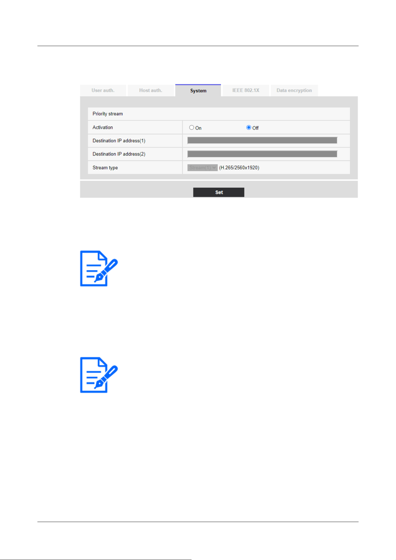
[Note:]
・If [Activation] is set to [On], the number of accessible users might be limited.
[Note:]
・[MULTI2U] Only [Destination IP address(1)] can be set.
image update speed, even if multiple users have access to it at the same time.
Priority stream
[Activation]
On/Off determines whether to use priority stream delivery.
[Destination IP address(1)]
Enter the IP address of the first destination.
[Destination IP address(2)]
Enter the IP address of the second destination.
[Stream type]
Select either [Stream(1)] or [Stream(2)].
[Stream (1)]:The stream (1) image is delivered.
[Stream (2)]:The stream (2) image is delivered.
15 [User mng.] to set authentication
15.3 [System] to set preference streams
478
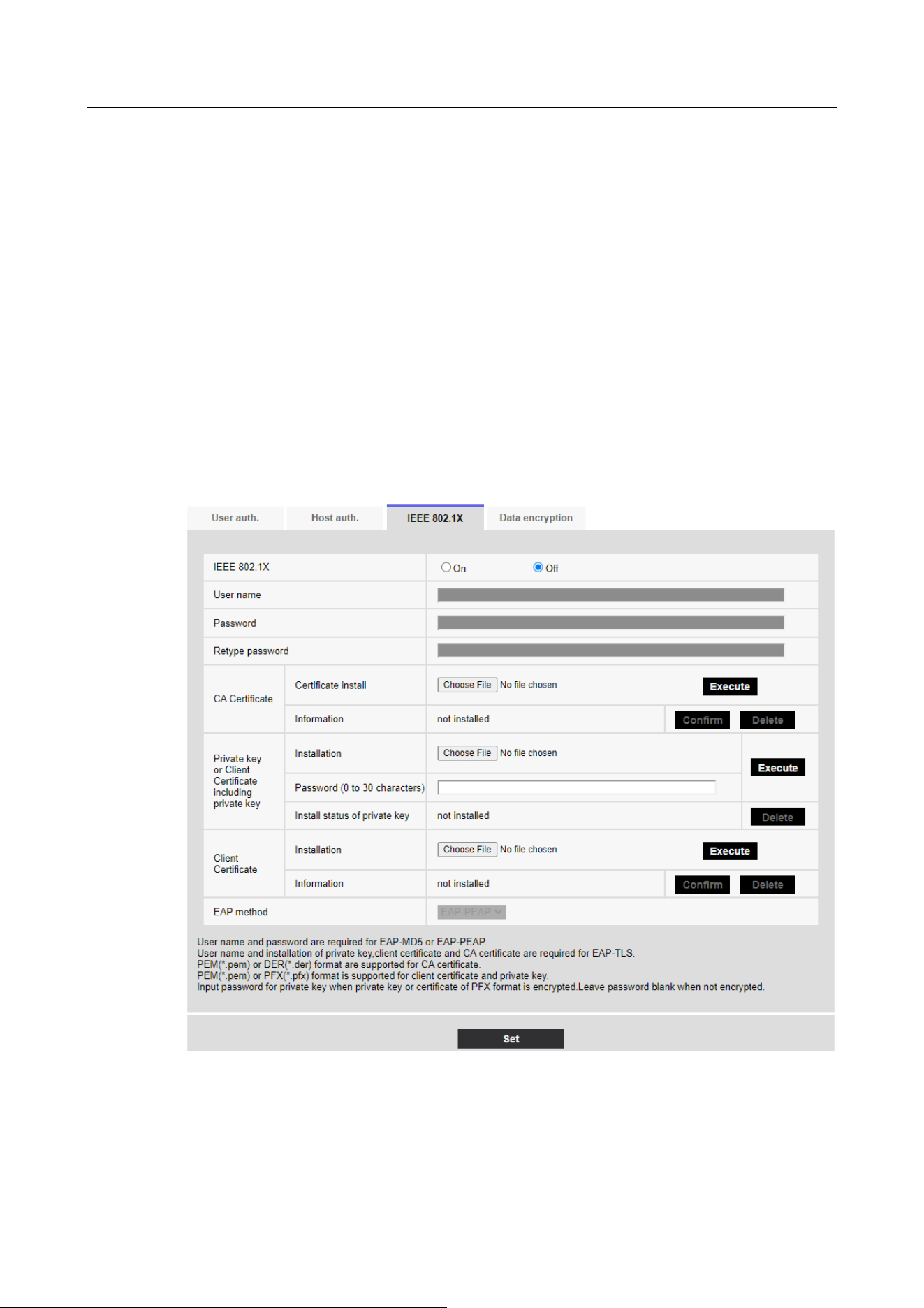
15.4 [IEEE 802.1X] to configure IEEE 802.1X
On the Users Admin page, press [IEEE 802.1X]. Refer to the following how to display and operate
the Advanced menu.
→5.1 How to display
→5.2 How to operate
Here, settings are made for IEEE 802.1X.
This function can be used to build a secure network environment using the authentication LAN
switch. For authentication LAN switches, contact your network administrator. The procedure
varies depending on the [EAP method]. Follow the procedure below. If [IEEE 802.1X] is [On],
start the setting with [IEEE 802.1X] set to [Off].
[IEEE 802.1X]
Configure on/off whether to perform port authentication by IEEE 802.1X.
[User name]
Enter the user name that accesses the authentication LAN switch or the user name registered
15 [User mng.] to set authentication
15.4 [IEEE 802.1X] to configure IEEE 802.1X
479

■CA Certificate Specifications
Item Specifications Remarks
Data format PEM format or DER
format
Extension pem or der
Maximum number of
certificates included in
the PEM format
1 piece
Maximum certificate size About 10 kB
[Note:]
・Verify that the CA certificate has not expired. If you use an expired certificate,
you may not be able to connect to the authentication LAN switch.
with the server.
Enter any username if it is not registered on the server.
Number of characters that can be entered:1 to 32 characters
Characters that cannot be entered:Full-pitch and half-pitch alphanumeric characters " & : ; ¥
[Password] [Retype password]
Enter the password to access the authentication LAN switch.
Number of characters that can be entered:4 to 32 characters
Characters that cannot be entered:Full-pitch and half-pitch alphanumeric characters " &
[CA Certificate] ‑ [Certificate install]
Install the root CA certificate. Do not include intermediate CA certificates.
Only when [IEEE 802.1X] is [Off] can you install it.
[CA Certificate] ‑ [Information]
Not installed:Have no certificates installed
[CA certificate host name]:Displayed when installed
[Expired]:Certificate expired
The [Execute] buttons enable you to view more information about CA certificates.
You can delete a CA certificate by using the [Delete] buttons.
[Private key or Client Certificate including private key]-[Installation]
Install a client certificate that contains a private key or private key.
Only when [IEEE 802.1X] is [Off] can you install it.
15 [User mng.] to set authentication
15.4 [IEEE 802.1X] to configure IEEE 802.1X
480

■Specification of Client Certificate with Private Key or Private Key
Item Specifications Remarks
Data format PEM format or PFX
format
Extension pem or pfx
Key length [bit] 1024/ 1536/ 2048/
3072/ 4096
Maximum number of
certificates included in the
PEM format
6 pieces
Maximum certificate size
(including intermediate CA
certificates)
About 10 kB
■ Client Certificate Specifications
Item Specifications Remarks
Data format PEM format Extension pem
Maximum number of
certificates included in the
PEM format
6 pieces
Maximum certificate size
(including intermediate CA
certificates)
About 10 kB
・[Private key or Client Certificate including private key]-[Password(0 to 30 characters)]
Enter the password if the private key is encrypted or if the password is set on a PFX client
certificate. If it is not encrypted, leave it blank.
Number of characters that can be entered:0 to 30 characters
・[Private key or Client Certificate including private key]-[Install status of private key]
Not installed:If not installed
Installed:If installed
The [Delete] buttons allow you to delete private keys.
・[Client Certificate] ‑ [Installation]
Install the client certificate.
If it is signed by an intermediate CA, install it with the intermediate CA certificate on the client
certificate.
Only when [IEEE 802.1X] is [Off] can you install it.
15 [User mng.] to set authentication
15.4 [IEEE 802.1X] to configure IEEE 802.1X
481

[Note:]
・Make sure the client certificate has not expired. If you use an expired certificate,
you may not be able to connect to the authentication LAN switch.
[Note:]
・If you upgrade while [EAP-MD5] is set in [EAP method], the [EAP method]
operates using [EAP-MD5]. Click the [Set] button to change [EAP method] to
the selected EAP method.
[Client Certificate] ‑ [Information]
Not installed:Have no certificates installed
[Host name of the certificate]:Displayed when installed
[Expired]:Certificate expired
The [Execute] buttons enable you to view more information about client certificates.
You can delete client certificates by using the [Delete] buttons.
[EAP method]
Select the authentication method from [EAP-PEAP], and [EAP-TLS].
EAP‑PEAP
1 Select [On] in [IEEE 802.1X].
2 Select [EAP-PEAP] in [EAP method].
3 Enter [User name] and [Password]/[Retype password] and press [Set].
EAP‑TLS
1 In the [CA Certificate] [Certificate install], click the Select Files button, select the CA
certificate, and then click the [Execute] button.
[Information] displays the host name (Common Name) you specified when creating certificates.
2 Click the File button on the Client Certificate that contains the private key or private key
and select the client certificate that contains the private key or private key.
3 Enter [Password] if the private key is encrypted or if the password is set to a PFX-based
client certificate. If it is not encrypted, leave it blank.
4 You install by clicking [Execute].
[Installed] is displayed on the [Install status of private key].
For Client Certificates containing private keys, the [Client Certificate] [Information] also
displays [Installed].
5 If you installed a private key in step 2, click the Select Files button on the [Client
Certificate], select the client certificate, and then click the [Execute] button.
15 [User mng.] to set authentication
15.4 [IEEE 802.1X] to configure IEEE 802.1X
482
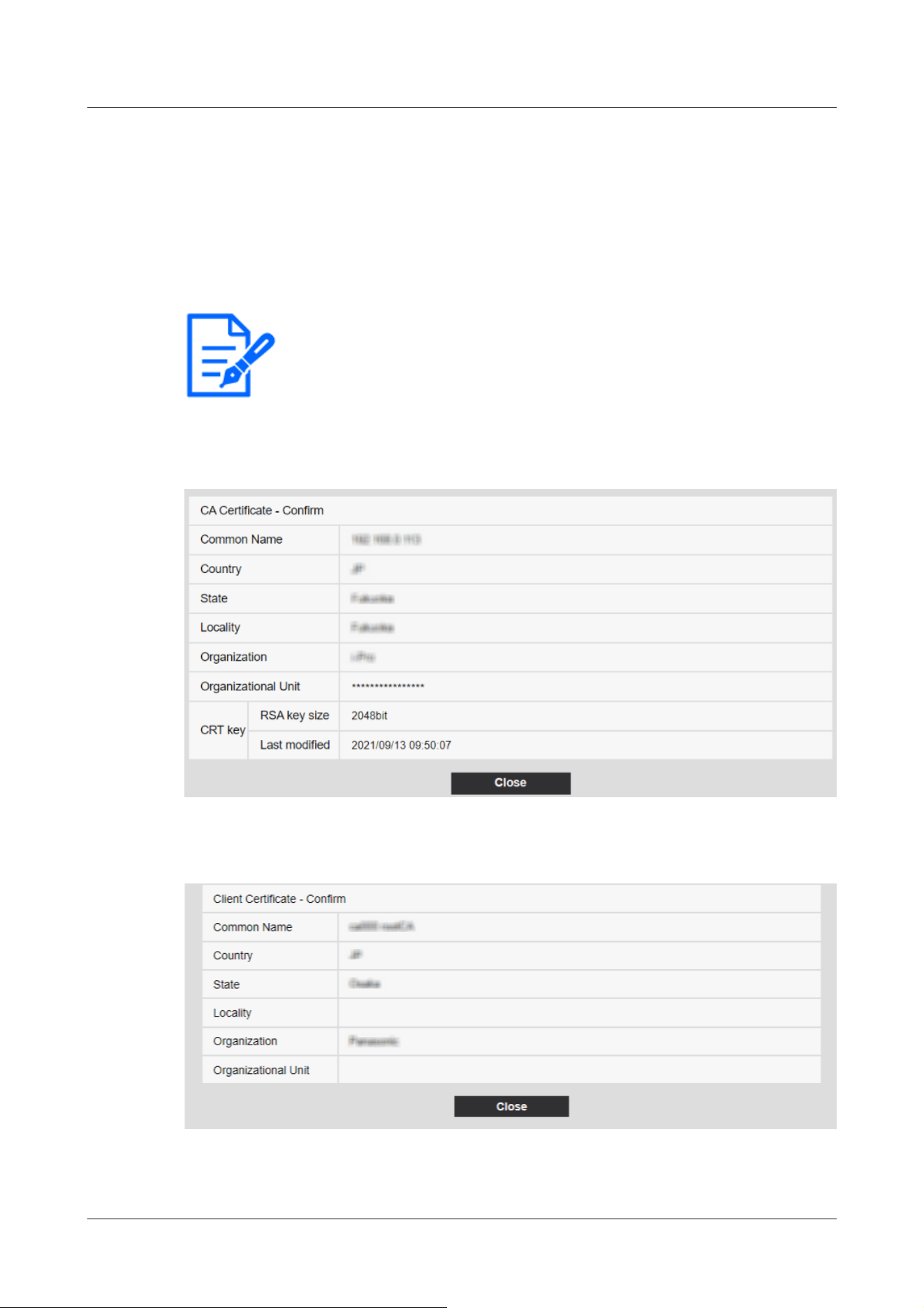
[Note:]
・To delete individual certificates, set [IEEE 802.1X] to [Off].
・Confirm that the CA and client certificates have not expired. The port
authentication feature may not be available if it is expired.
[Information] displays the host name (Common Name) you specified when creating certificates.
6 Select [On] in [IEEE 802.1X] and select [EAP-TLS] in [EAP method].
7 Enter the user name registered with the server in [User name] and press [Set].
Enter any username if it is not registered on the server.
You do not need to enter [Password]/[Retype password].
Example of [CA Certificate Confirmation] window
[Client Certificate Confirmation Screen] example
15 [User mng.] to set authentication
15.4 [IEEE 802.1X] to configure IEEE 802.1X
483

[Important]
・If the camera cannot be accessed for some reason after the camera is set to [On]
by [IEEE 802.1X], connect the camera to an unauthenticated switch or port.
IEEE802.1X will be disabled and the camera will be accessible.
・If the client certificate contains an intermediate CA certificate, the client
certificate must be first followed by the order of the intermediate CA certificate.
・When a certificate exceeding 10 kB is installed, no error is displayed during
installation, but error may occur during connection.
15.5 [Data encryption] for setting up data encryption
On the Users Admin page, press [Data encryption]. Refer to the following how to display and
operate the Advanced menu.
→5.1 How to display
→5.2 How to operate
Here, the data encryption settings are made.
The data encryption settings for each camera are described below.
PTZ camera, Fixed cameras
Click + on the left side of the setting screen to expand the item and display the detailed setting.
Click-> on the left of each expanded item to return to the previous window.
[Data encryption (Batch change)]Use [On]/[Off] to enable/disable encryption.
[On]:Enable data encryption. Encrypt all streams, all JPEG, and audio [AAC-LC].
[Off]:Disables data encryption.
[Stream], [JPEG]
[On] and [Off] individually configure whether to enable data encryption for each stream and each
JPEG.
[Encryption password], [Retype encryption password]
Set the data encryption password.
Number of characters that can be entered:4 to 16 characters
Characters that cannot be entered:Double-byte and single-byte symbols " &
15 [User mng.] to set authentication
15.5 [Data encryption] for setting up data encryption
484

[Important]
・When setting data encryption to [On], it is recommended that the total bit rate
of the streams be set to 16 Mbps or less.
・When data encryption is set to [On], images cannot be viewed by browsers. To
view the encrypted video, use our compatible equipment.
・Data-encrypted MP4 files and JPEG images cannot be viewed on the browser
playback page. Download to the PC and check with the decoding tool. For
decoding tools, please refer to our technical information website<Control No.
C0310>.
[Note:]
・If [Data encryption (Batch change)] is [On], the audio [AAC-LC] is encrypted
([G.726] [G.711] is not encrypted). To encrypt both video and audio, set [Data
encryption (Batch change)] to [On] and set the audio [Audio input encoding
format] to [AAC-LC].
・For encrypted MP4 files and JPEG images, the video can be viewed using a
decoding tool.
・[New X Fixed-8MP][New X Fixed-6MP][New X Fixed-5MP][AI Outdoor IR
BulletX-8M][AI Outdoor IR BulletX-5M]If [Image capture mode] is set to [60fps
Mode] or [50fps Mode], [Encryption] of [Stream(2)] to [Stream(4)] and [JPEG(1)]
[JPEG(2)] cannot be changed to [On].
[Note:]
・The [Multi-sensor + PTZ] is displayed only for Multi-directional + PTZ.
Displaying pull-down menus when data encryption is enabled
For streams with data encryption enabled in both the [Live view] pull-down menu and the
in-screen pull-down menu<Encrypted>The message is displayed.
[Live view] pull-down menu on the live screen
15 [User mng.] to set authentication
15.5 [Data encryption] for setting up data encryption
485
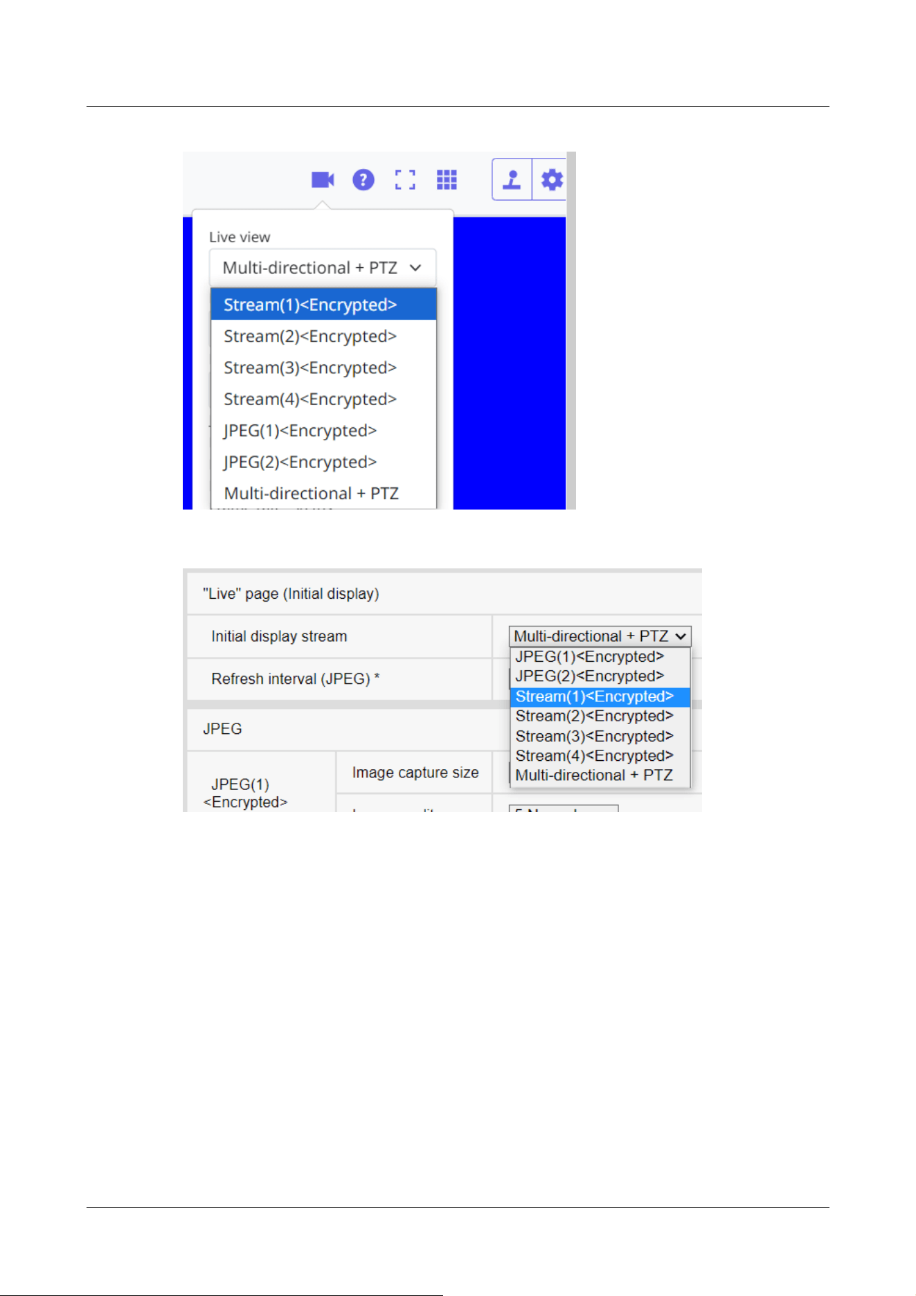
[Live view] pull-down menu in the setting window
Multi-directional camera
Set the data encryption for each stream separately.
15 [User mng.] to set authentication
15.5 [Data encryption] for setting up data encryption
486
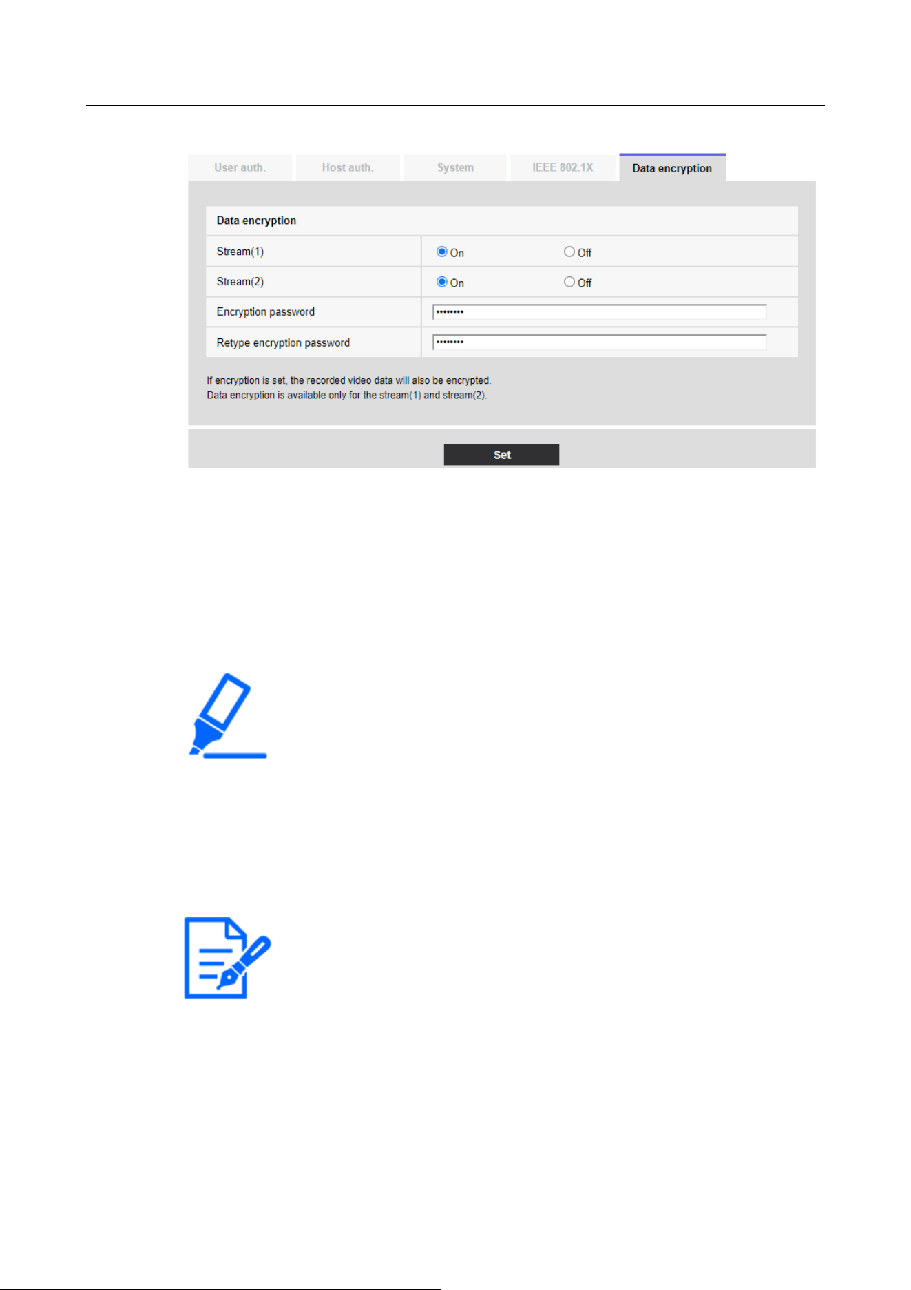
[Important]
・JPEG cannot encrypt data.
・When setting data encryption to [On], it is recommended that the total bit rate
of the streams be set to 64 Mbps or less.
・The data-encrypted MP4 file cannot be viewed on the browser playback page.
Download to the PC and check with the decoding tool. For decoding tools, please
refer to our technical information website<Control No. C0310>.
→2.8 Play back images on the SD Memory Card
[Note:]
・When the [Data encryption] of all streams is set to [On], the audio [AAC-LC] is
encrypted ([G.726] [G.711] is not encrypted). If [AAC-LC] is selected in [Audio
input encoding format], the sound will not be played while JPEG is displayed in
live picture.
・For encrypted MP4 files, the video can be viewed using the decryption tool.
[Stream]
Enable/disable data encryption for each stream separately.
[Encryption password], [Retype encryption password]
Set the data encryption password.
Number of characters that can be entered:4~16
Characters that cannot be entered:Double-byte and single-byte symbols&
Displaying pull-down menus when data encryption is enabled
For streams with data encryption enabled in the [Live view] pull-down menu<Encrypted>The
15 [User mng.] to set authentication
15.5 [Data encryption] for setting up data encryption
487
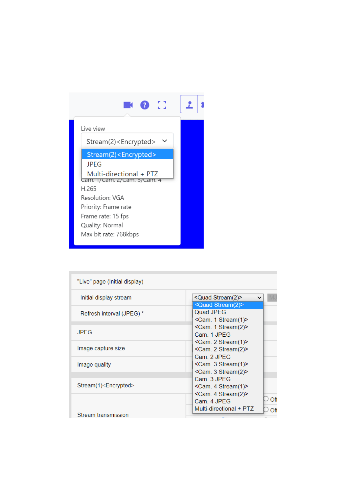
message is displayed. Also, in the pull-down menu in the setting screen, streams with valid data
encryption are displayed in <>.
[Live view] pull-down menu on the live screen
[Live view] pull-down menu in the setting window
15 [User mng.] to set authentication
15.5 [Data encryption] for setting up data encryption
488

15.6 [Security] to configure security
On the Users Admin page, press [Data encryption]. Refer to the following how to display and
operate the Advanced menu.
→5.1 How to display
→5.2 How to operate
Here, the data encryption settings are made.
Brute force attack countermeasures
Configure settings related to brute force attack countermeasures.
If you enter the wrong user name or password the specified number of times and within the time
set in [Blocking conditions], you cannot access your browser or SNMP/FTP for the period set in
[Blocking period].
For example, when using the settings on the screen shown above ([Browser access blocking
period]: 30s, [Browser access blocking conditions] (times): 5 times, [Browser access blocking
conditions] (s): 10s), if your login attempt fails 5 times within 10 seconds, the login page will not be
displayed for 30 seconds.
Browser access blocking period (s)
Set the length of time the browser cannot be accessed.
Input range: 10 to 1000(s)
Browser access blocking conditions - Input range (times)
Set the conditions (number of failed attempts) before access to the browser is prohibited.
Input range: 1 to 5 (times)
Browser access blocking conditions - Input range (s)
Set the conditions (specified length of time) before access to the browser is prohibited.
Input range: 1 to 100 (s)
SNMP/FTP access blocking period (s)
15 [User mng.] to set authentication
15.6 [Security] to configure security
489

[Note:]
・If you want to use the browser access blocking function in [Brute force attack
countermeasures], set [User auth.] to [On] on the [User auth.] tab.
[IMPORTANT]
・If [Browser Access] is set to [Disable], access to live images is disabled.
・To switch [Browser Access] from [Disable] to [Enable], you need to initialize the
setting data.
Refer to the camera's Operating Instructions for details on initializing the settings.
Set the length of time the SNMP/FTP cannot be accessed.
Input range: 10 to 1000(s)
SNMP/FTP access blocking conditions - Input range (times)
Set the conditions (number of failed attempts) before access to the SNMP/FTP is prohibited.
Input range: 1 to 5 (times)
SNMP/FTP access blocking conditions - Input range (s)
Set the conditions (specified length of time) before access to the SNMP/FTP is prohibited.
Input range: 1 to 100(s)
Browser Access
Set whether or not to enable/disable browser access.
15 [User mng.] to set authentication
15.6 [Security] to configure security
490

[Note:]
・The items that can be set differ depending on the function of the model.
・Refer to the catalog specifications for the functions installed in each model.
[Note:]
・Contact your network administrator for the address settings for each server.
・To connect a camera to a router and access the camera via the Internet, you
must configure a separate HTTP port number for each network camera, and use
the router's port forwarding features to translate addresses. For details, refer to
your router's instruction manual.
・Port forwarding functions are used to convert global IP addresses to private IP
addresses, such as Static IP Mascalade and Network Address Translation (NAT).
This feature is configured on the router.
16 Networking configuration [Network]
Network pages configure network settings.
Network pages consist of the [Network] tab and the [Advanced] tab.
16.1 Networking [Network]
On the Network Page, press the [Network] tab. Refer to the following how to display and operate
the Advanced menu.
→5.1 How to display
→5.2 How to operate
The following information is required to configure the network.
Check with your network administrator or Internet service provider.
・IP address
・Subnet Mask
・Default Gateway (with Gateway Server Router)
・HTTP port
・Primary server address for DNS, secondary server address (when DNS is used)
16 Networking configuration [Network]
16.1 Networking [Network]
491
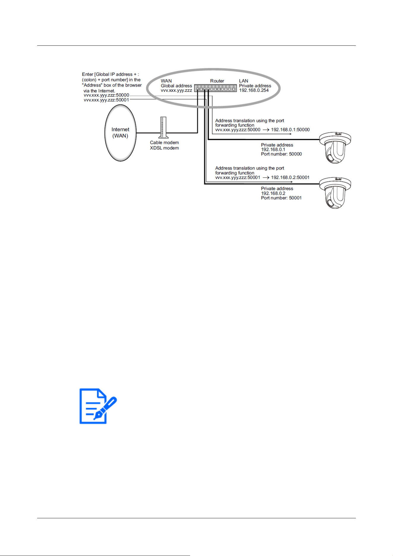
[Note:]
・If the IP address cannot be retrieved from the DHCP server in AutoIP, search for
the IP address that is not used in the same network between 169.254.1.0 and
169.254.254.255 and set the IP address.
・[MULTI_PTZ] In DHCP/Auto setting (Omakase), if the DHCP server is not
found, set the IP address of the PTZ camera to 192.168.0.10 and the IP address o
f
the Multi-directional camera to 192.168.0.11.
IPv4 network
[Network Settings]
Select how to set the IP address.
[Static]:Enter the IP address into the [IP address(IPv4)] to set the IP address.
[DHCP]:Set the IP address using the DHCP function. If you cannot obtain an IP address from the
DHCP server, set the IP address to 192.168.0.10. Subsequently, if you obtain an IP address from
a DHCP server, you change it to the IP address.
[Auto(AutoIP)]:Set the IP address using the DHCP function. If the DHCP server is not found, the
IP address is automatically configured.
[Auto(Advanced)]:Using the DHCP function, refer to the network address information and set the
unused IP address to the camera as the fixed IP address. The camera automatically determines the
set IP address within the range of the subnet mask. If the DHCP server is not found, set the IP
address to 192.168.0.10.
[IP address(IPv4)]
When the DHCP function is not used, enter the IP address of the computer. Do not overlap with
16 Networking configuration [Network]
16.1 Networking [Network]
492

[Note:]
・Multiple IP addresses are not available even when the DHCP function is used.
Contact your network administrator for the DHCP server configuration.
[Note:]
・Multiple IP addresses are not available for the default gateway, even if you use the
DHCP facility. Contact your network administrator for the DHCP server
configuration.
[Important]
・When IPv6 is accessed, the stream image cannot be displayed on the live screen.
If you want to display the stream image on the live screen, please access it via
IPv4.
the IP address set on the PC or other network camera.
[Subnet mask]
When the DHCP function is not used, enter the subnet mask of the computer.
[Default gateway]
If you do not use the DHCP function, enter the default gateway for your computer.
[DNS]
Specify whether the DNS server addresses are automatically acquired ([Auto]) or manually
entered ([Manual]).
When set to [Manual], you need to configure the DNS server IP addresses.
If you use the DHCP function, you can automatically obtain the DNS server address by setting it
to [Auto].
Contact your system administrator for the setting.
[Primary server address], [Secondary server address]
If you use [DNS] with [Manual], enter the IP address of the DNS server.
Contact your system administrator for the IP address of the DNS server.
[Host name]
Enter the host name to be used with the DHCP function.
Available number of characters:1 to 64 characters
Available characters:Alphanumeric characters, the period (.), and the hyphen (-).
IPv6 network
[Manual]
16 Networking configuration [Network]
16.1 Networking [Network]
493

[Note:]
・When connecting over a router with a manually configured IP address, enable the
automatic configuration feature for IPv6 addresses using IPv6-compatible routers.
Configure an IPv6 address that contains prefix information provided by
IPv6-compatible routers. For details, refer to your router's instruction manual.
[Note:]
・Some ports may not be accessed by some browsers. If access is lost, use HTTPS
or the i-PRO Setup Tool (iCT) to change the port number.
・[MULTI] The port numbers 32768 to 49151 cannot be set.
Configure [On] and [Off] to manually configure IPv6 addresses.
[On]:Manually enter the IPv6 address.
[Off]:IPv6 address cannot be entered manually.
[IP address(IPv6)]
If [Manual] is set to [On], IPv6 addresses must be entered manually.
Enter to avoid duplication with other devices.
[Default gateway]
Enter the default gateway for the IPv6 network when the IPv6 network [Manual] is [On].
[DHCPv6]
You can configure [On]/[Off] to use the IPv6 DHCP feature.
Configure the DHCP server so that the PC and other network cameras that do not use the DHCP
function do not have the same IP address. Contact your network administrator for server
configuration.
[Primary DNS server address], [Secondary DNS server address]
Enter the IPv6 address of the DNS server. Contact your system administrator for the IPv6 address
of the DNS server.
Common
[HTTP port]
Assign individual port numbers.
Configurable port number:1~65535
The following port numbers cannot be set because they are used by this computer.
20、 21、 22、 23、 25、 42、 53、 67、 68、 69、 80、 110、 123、 161、 162、 443、 554、 995、 1883、
8883、 10669、 10670、 59000~61000
[Line speed]
Select the data communication speed from the following. Normally, it is recommended to use the
16 Networking configuration [Network]
16.1 Networking [Network]
494

[Note:]
・Refer to the catalog specifications for the functions installed in each model.
・If [64 kbps] is selected, set the [Audio transmission mode] on the [Audio] tab to
[Off].
.
]
default [Auto].
[Auto]:The communication speed is set automatically.
[100 M‑Full]:100 Mbps full duplex
[100 M‑Half]:100 Mbps half duplex
[10 M‑Full]:10 Mbps full duplex
[10 M‑Half]:10 Mbps half duplex
[Max RTP packet size]
Set whether to limit the size of RTP packets sent from the camera when viewing camera images
using RTP. Normally, it is recommended to use the [1,500 bytes] option.
If the packet size of the communication line is limited, select [Restricted (1280 bytes)]. Contact
the network administrator for the maximum packet size of the communication line.
[HTTP max segment size(MSS)]
Set whether to limit the maximum segment size (MSS) sent from the camera when viewing the
camera image using HTTP. Usually, it is recommended to use the default settings.
If the maximum segment size (MSS) of the communication line to be used is limited, select [1024
Byte]/[Restricted (1280 Byte)]. Contact your network administrator for the maximum segment
size (MSS) of the communication line.
[Bandwidth control(bit rate)]
Select the amount of data delivered from the following.
[MULTI4][MULTI3][MULTI2S]
[Unlimited]/4096kbps/ 6144kbps/ 8192kbps/ 10240kbps/ 12288kbps/ 15360kbps/ 20480kbps/
25600kbps/ 30720kbps/ 35840kbps/ 40960kbps/ 51200kbps/ 61440kbps/ 81920kbps/
102400kbps/ 153600kbps
[PTZ][CompactX][CompactS][New X Fixed][AI Outdoor IR Bullet][U-series AI]
[Unlimited]/64kbps/ 128kbps/ 256kbps/ 384kbps/ 512kbps/ 768kbps/ 1024kbps/ 2048kbps/
4096kbps/ 6144kbps/ 8192kbps/ 10240kbps/ 15360kbps/ 20480kbps/ 25600kbps/ 30720kbps/
35840kbps/ 40960kbps/ 51200kbps
[MULTI2U]
[Unlimited]/128kbps/ 256kbps/ 384kbps/ 512kbps/ 768kbps/ 1024kbps/ 2048kbps/ 4096kbps/
6144kbps/ 8192kbps/ 10240kbps/ 15360kbps/ 20480kbps/ 25600kbps/ 30720kbps/ 35840kbps/
40960kbps/ 51200kbps/ 61440kbps
16 Networking configuration [Network]
16.1 Networking [Network]
495

→10.5 [Audio] for setting sound
・If [Bandwidth control(bit rate)] is set low, the snapshot button may not work
depending on the operating environment. If so, select [JPEG] on the live page and
run the snapshot with the smallest resolution delivered.
・[MULTI] When playing back images stored on the SD Memory Card, the
[Bandwidth control(bit rate)] must be set to [Unlimited] or above [51200 kbps].
[Note:]
・Camera display with the IP easy setting software is always enabled and the camera
screen can be opened.
[Important]
・If you allow FTP access to the camera, there is a possibility that authentication
information (user names, passwords, etc.) will be leaked when accessing the
camera from a PC.
[Easy IP Setup accommodate period]
Set the time to enable Network Settings from IP-based Simple Configuration Software to either
[20min] or [Unlimited] after the computer starts.
[20 minutes]:The camera setting operation using the IP easy setting software is enabled only for
20 minutes after starting the machine.
[Unlimited]:The camera setting operation in the IP easy setting software is always enabled.
[FTP access to camera]
Use [Allow] or [Forbid] to set whether or not to allow FTP access to the cameras.
[Permission]:Allow FTP access to the camera.
[Prohibition]:FTP access to the camera is prohibited.
[ONVIF®]
Use [On]/[Off] to set whether to use the ONVIF function.
[Enable]:You can use the ONVIF function.
[Disabled]:The ONVIF function cannot be used.
16.2 [Advanced] for advanced networking settings
On the Network Page, press the [Advanced] tab. Refer to the following how to display and operate
16 Networking configuration [Network]
16.2 [Advanced] for advanced networking settings
496
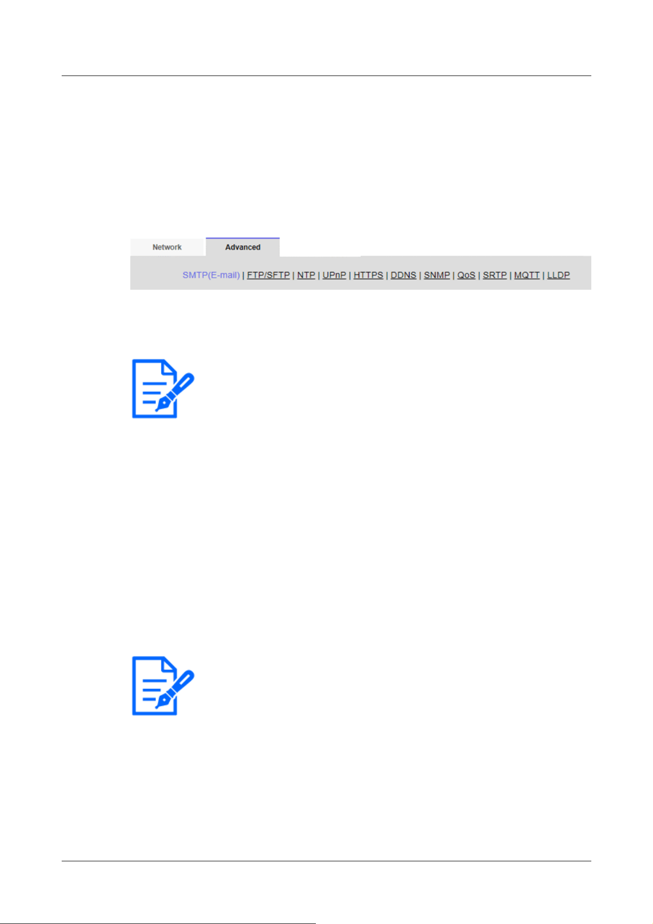
[Note:]
・The items that can be set differ depending on the function of the model.
・Refer to the catalog specifications for the functions installed in each model.
[Note:]
・[New X Fixed-8MP][New X Fixed-6MP][New X Fixed-5MP][AI Outdoor IR
BulletX-8M][AI Outdoor IR BulletX-5M][Alarm image attachment] is not
available when [Image capture mode] is set to [60fps Mode] or [50fps Mode].
the Advanced menu.
→5.1 How to display
→5.2 How to operate
Here, the SMTP (mail), FTP/SFTP, NTP, UPnP, HTTPS, DDNS, SNMP, QoS, SRTP, MQTT,
and LLDP functions are set.
Click the link to each item to navigate to each setting page.
16.2.1 Set mail sending
[E-mail notification]
On/Off is used to specify whether to send mail in the following cases.
When an alarm is activated (e-mail to [Alarm] field)
When notifying the remaining capacity of the SD Memory Card (mail notifying destination: [Diag.]
field)
When the free space of the SD Memory Card is insufficient (mail to send message to: [Diag.] field)
SD Memory Card recognition errors (mail notification destination: [Diag.] field)
When writing to SD Memory Card is failed (unique alarm notification destination: [Diag.] field)
[Alarm image attachment]
On/Off sets whether or not to attach images when sending mail by alarm detection.
[Image capture size]
Select the resolution of the image to be attached to the alarm mail from the following.
JPEG(1)/ JPEG(2)
[SMTP server address]
16 Networking configuration [Network]
16.2 [Advanced] for advanced networking settings
497

[Important]
・To enter a hostname for [SMTP server address] [POP server address], you must
configure the DNS on the [Network] tab of the network page.
→16.1 Networking [Network]
・[MULTI] The port numbers 32768 to 49151 cannot be set.
[Note:]
・If you do not know how to authenticate e-mail, contact your network administrator.
Enter the IP address or host name of the SMTP server to send e-mail.
Number of characters that can be entered:1 to 128 characters
Input Characters:One-byte alphanumeric and one-byte symbols : . _ ‑
[SMTP port]
Enter the port number to send mail.
Configurable port number:1~65535
The following port numbers cannot be set because they are used by this computer.
20、 21、 22、 23、 42、 53、 67、 68、 69、 80、 110、 123、 161、 162、 443、 554、 995、 1883、
8883、 10669、 10670、 59000~61000
[POP server address]
If you selected [POP before SMTP] in [Type], enter the IP address or hostname of the POP
server.
Number of characters that can be entered:1 to 128 characters
Input Characters:One-byte alphanumeric and one-byte symbols : . _ ‑
Authentication
[Type]
Select the authentication method for sending mail from the list below.
None:Without authentication
POP before SMTP:Prior to sending e-mail, authenticate the POP server that receives the e-mail.
SMTP:Authenticate the SMTP server.
[User name]
Enter the username that you want to access the server.
Number of characters that can be entered:0 to 32 characters
Characters that cannot be entered:Double-byte and single-byte symbols " & : ; ¥
[Password]
16 Networking configuration [Network]
16.2 [Advanced] for advanced networking settings
498

[Note:]
・Some SMTP servers may not support SSL.
・The SMTP over SSL method is supported. STARTTLS is not supported.
・If set to [On], you might need to set the SMTP port number to 465. Check with
your provider for details.
Enter the password to access the server.
Number of characters that can be entered:0 to 128 characters
Characters that cannot be entered:Double-byte and single-byte symbols " &
[Sender's E-mail address]
Enter the sender's mail address.
The entered mail address is displayed in the From field of the received mail.
Number of characters that can be entered:3 to 128 characters
Input Characters:Half-pitch alphanumeric and half-pitch symbols @ . _ ‑
[SSL]
When sending [Alarm Notification] or [Diag.] mail notification in SSL-encrypted format, set it to
[On]. When set to [On], the authentication method is set to [SMTP]. Configure the [User name]
and [Password] for authentication.
[Address 1] through [Address 4]
Set the mail address of the notification destination. You can set up to 4 notification destinations.
Number of characters that can be entered:3 to 128 characters
Input Characters:Half-pitch alphanumeric and half-pitch symbols @ . _ ‑
To delete a set e-mail address, press [Delete] for the e-mail address to delete.
[Terminal 1]:Mail is notified when an alarm is generated at terminal 1.
[Terminal 2]:Mail is notified when an alarm is generated at terminal 2.
[Terminal 3]:Mail is notified when an alarm is generated at terminal 3.
[VMD]:Mail is notified when operation is detected.
[SCD]:Notifies by e-mail when undesired detection occurs.
[Command Alarm]:Mail notification is executed when a command alarm is entered.
[Audio detection]:Mail is notified when sound is detected.
[Impact detection]:Mail is notified when impact detection is detected.
[Casing open detection]:Mail is notified when opening detection is detected.
[Diag.]:
-SD Memory Card Remaining capacity notification
-SD Memory Card with insufficient free space
-SD Memory Card recognition error
16 Networking configuration [Network]
16.2 [Advanced] for advanced networking settings
499

[Note:]
・Message recipient The diagnostic mail notified when the [Diag.] field is checked
does not reflect the [E-mail subject] and [E-mail body] settings set below.
[Auto track]:Mail is notified when an automatic tracking alarm is generated.
[E-mail subject(Alarm)]
Enter the subject of the alarm mail.
Number of characters that can be entered:0 to 50 characters
Use the camera title:The camera title is displayed in the mail subject line.
Cause of alarm:Add an alarm factor to the email subject.
[E-mail subject(Diag.)]
Enter the subject of the diagnosis mail.
Number of characters that can be entered:0 to 50 characters
Use the camera title:The camera title is displayed in the mail subject line.
[E-mail body(Alarm)]
Enter the body of the alarm message.
Number of characters that can be entered:0 to 200 characters
Cause of alarm:The alarm cause %p% is added to the message body. The %p% is sent in place of the
cause of the alarm.
For operation detection alarm: "VMD"
For undesired detection alarm: "SCD"
For auto-tracking alarm: "AT"
For intrusion alarm by AI-VMD: "INT"
For residence alarm by AI-VMD: "LOI"
For direction alarm by AI-VMD: "DIR"
For line cross alarm by AI-VMD: CLD
For the terminal alarm: The terminal names set in [Terminal 1], [Terminal 2], and [Terminal 3] of
the [Terminal name]. (For example, if the name of terminal 1 is [Terminal 1], "Terminal 1")
For command alarm: "CMD"
In the case of the sound detection alarm (AI sound identification target: gunshot): "Audio
detection gunshot"
In the case of the sound detection alarm (AI sound identification target: screaming): "Audio
detection yell"
In the case of the sound detection alarm (AI sound identification target: horn): "Audio detection
Vehicle Horn"
16 Networking configuration [Network]
16.2 [Advanced] for advanced networking settings
500

[Note:]
・[MULTI] In the case of an operation detection alarm and disturbance detection
alarm, information to identify the camera is given by the detected camera.
For the operation detection alarm of camera 1: "VMD(CH1)"
For the operation detection alarm of camera 2: "VMD(CH2)"
For the operation detection alarm of camera 3: "VMD(CH3)"
For the operation detection alarm of camera 4: "VMD(CH4)"
For undesired detection alarm of camera 1: "SCD (CH1)"
For undesired detection alarm of camera 2: "SCD(CH2)"
For the disturbance detection alarm of camera 3: "SCD(CH3)"
For the disturbance detection alarm of camera 4: "SCD(CH4)"
[Note:]
・If the SD Memory Card has no free space, [SD Memory Card is FULL] or [SD
Memory Card cannot be recognized] is sent.
・By describing the substitute characters in the message text, the cause type and
the time of alarm can be automatically assigned.
Alternate character alarm factor: %p%, occurrence time: %t%
(Example of Use)
When the operation detection alarm is generated at 19:13:24 after setting the
following character string in the mail body.
Set mail text: %p%alarm occurred at %t%.
In the case of the sound detection alarm (AI sound identification target: cracking of glass): "Audio
detection Glass break"
In the case of sound detection alarm (AI sound identification target: Others): "Audio detection"
For impact detection alarm: "Impact detection"
For opening detection alarm:
When the detection operation is [Alarm notification when the front cover both opening and
closing]:
If the camera front cover has been opened: "Casing open detection Open"
If the camera front cover is closed: "Casing open detection Close"
When the detection operation is [Alarm notification continue while the front cover is open]:
If the camera front cover has been opened: "Casing open detection Open"
Occurrence time:The occurrence time %t% is added to the message text. The %t% is replaced by
the time the alarm occurred (hour: minute: second).
16 Networking configuration [Network]
16.2 [Advanced] for advanced networking settings
501
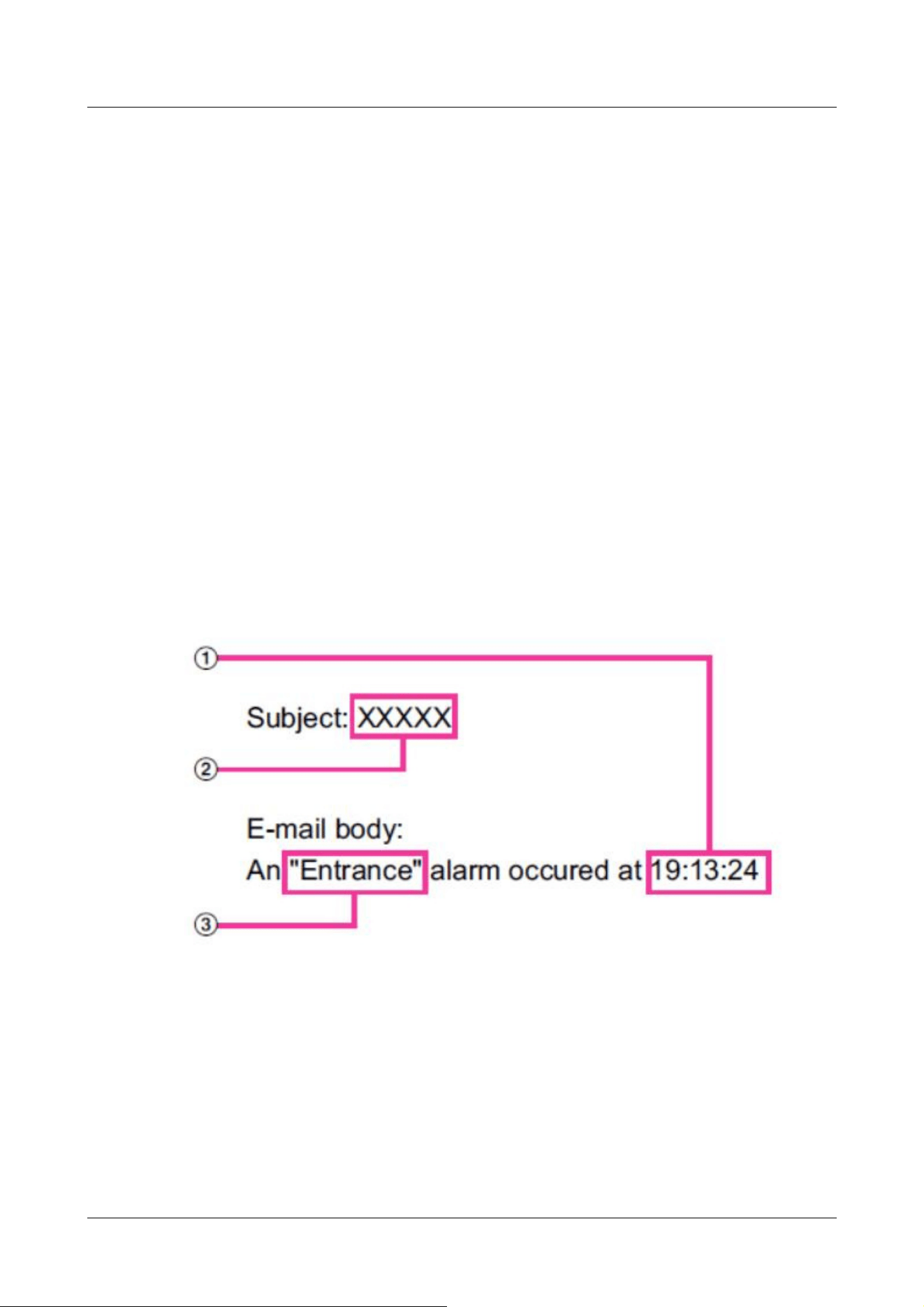
Message text: ["VMD" alarm was generated at 19:13:24].
If the body is blank, the email languages that are sent are determined by the
[Menu language] of the [Basic].
Specifying [Japanese] sends e-mail in Japanese or in other languages.
[Terminal 1 (Up to 10 characters)]
Enter the name of Terminal 1 used for alarm factors in the mail body.
Characters that cannot be entered:Single-byte characters " &
[Terminal 2 (Up to 10 characters)]
Enter the name of terminal 2 used for alarm factors in the mail body.
Characters that cannot be entered:Single-byte characters " &
[Terminal 3 (Up to 10 characters)]
Enter the name of terminal 3 used for alarm cause in the mail body.
Characters that cannot be entered:Single-byte characters " &
Mail notification example
Mail format when checkbox for camera title is specified in mail subject and check box for alarm
factor/occurrence time is specified in mail body
① The alarm time is assigned.
② The camera title is used for the e-mail subject.
③ The name specified by terminal names 1 to 3, which are alarm factors, is given.
16.2.2 Configuring FTP/SFTP transmission function
FTP (File Transfer Protocol) and SFTP (SSH File Transfer Protocol) are file transfer protocols
16 Networking configuration [Network]
16.2 [Advanced] for advanced networking settings
502

[Note:]
・The factors displayed differ depending on the function of the model.
・Refer to the catalog specifications for the functions installed in each model.
used to send images to servers.
SFTP can safely send images to the server using an SSH (Secure Shell) encrypted data stream.
The following two transmission functions are available.
・Image sent when alarm is generated
・Transmit images periodically
16 Networking configuration [Network]
16.2 [Advanced] for advanced networking settings
503
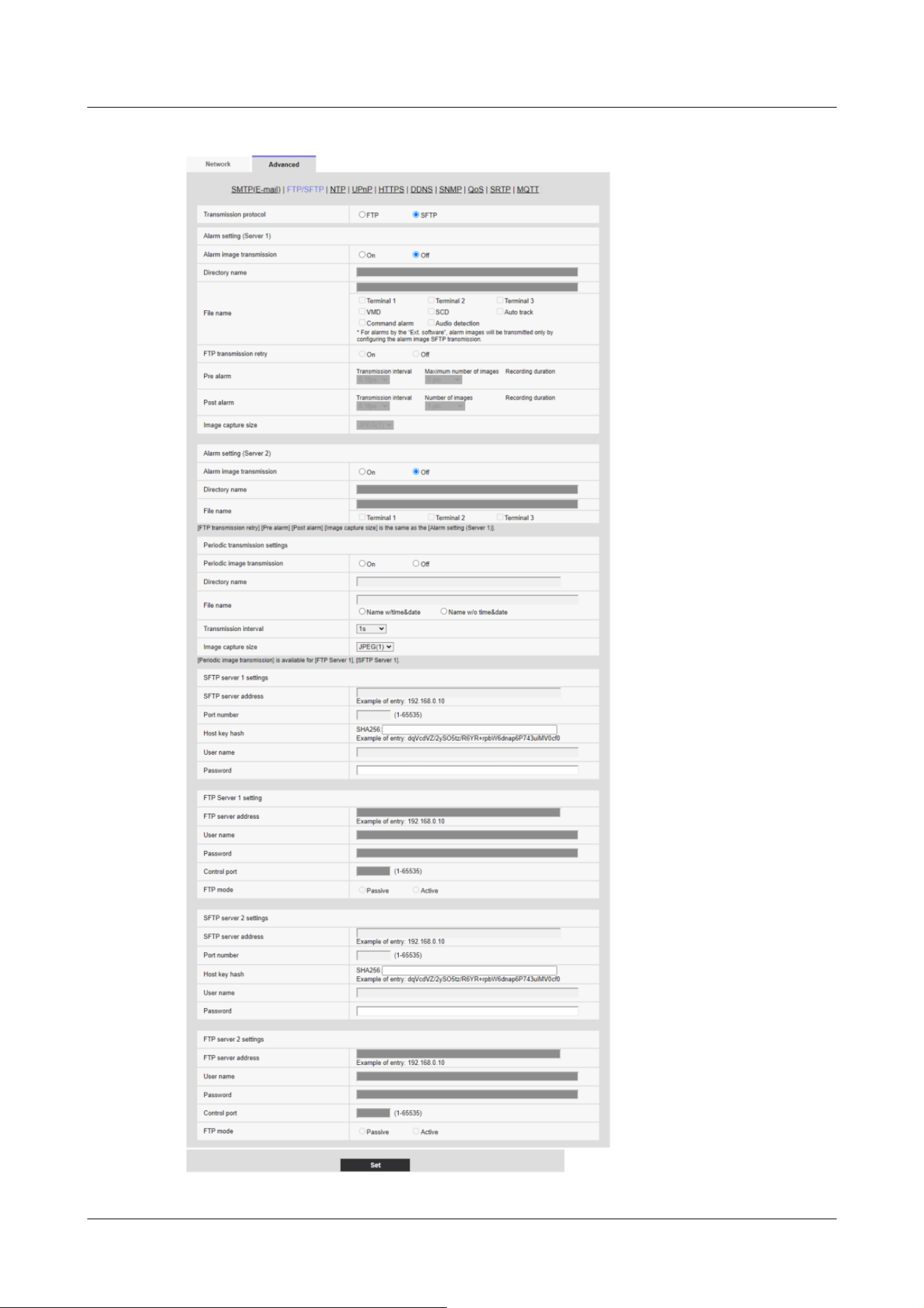
16 Networking configuration [Network]
16.2 [Advanced] for advanced networking settings
504

[Important]
・If FTP is selected in the protocol setting, FTP server authentication information
(user name, password) may be leaked on the network when sending images to the
FTP server. Use of SFTP is recommended.
[Note:]
・[New X Fixed-8MP][New X Fixed-6MP][New X Fixed-5MP][AI Outdoor IR
BulletX-8M][AI Outdoor IR BulletX-5M][Alarm image transmission] is not
available when [Image capture mode] is set to [60fps Mode] or [50fps Mode].
[Transmission protocol]
Configure the protocol with the destination server by selecting it from FTP/SFTP.
SFTP:Use SFTP as the protocol for communicating with the server.
FTP:Use FTP as the protocol to communicate with the server.
Alarm settingFixed
Alarm setting (server 1)
[Alarm image transmission]
Select [On] or [Off] to determine whether or not to transmit images when an alarm is detected.
[On]:Transmits an image to the server when an alarm has occurred.
[Off]:Does not transmit an image to the server when an alarm has occurred.
[Directory name]
Enter the directory name where the alarm images are to be saved.
For example, enter [/ALARM] to designate the directory [ALARM] under the root directory of
the server.
Number of characters that can be entered:1 to 256 characters
Characters that cannot be entered:Double-byte and single-byte symbols " & ;
[File name]
Enter the file name used for the alarm image to be transmitted to the server. The file name will be
as follows.
File name:File name entered + Date and time (year, month, day, minute, second) + Sequence
number
Number of characters that can be entered:1 to 32 characters
Characters that cannot be entered:Double-byte and single-byte symbols " & * / : ; < > ? ¥ ¦
When [On] is selected for [Alarm image FTP transmission], you can select the alarm type from the
following.
[Terminal 1]:Transmit the image to the server when an alarm occurs in Terminal 1.
16 Networking configuration [Network]
16.2 [Advanced] for advanced networking settings
505

[Note:]
・The items that can be set differ depending on the function of the model.
・Refer to the catalog specifications for the functions installed in each model.
[Note:]
・When SFTP is selected in [Transmission protocol] settings, FTP transmission
retry is unavailable.
・When 2fps or 3fps is selected in [Refresh interval], FTP transmission retry is
unavailable.
[Terminal 2]:Transmit the image to the server when an alarm occurs in Terminal 2.
[Terminal 3]:Transmit the image to the server when an alarm occurs in Terminal 3.
[VMD]:Transmit the image to the server when motion is detected.
[SCD]:Transmit the image to the server when SCD (scene change detection) occurs.
[Auto track]:Transmit the image to the server when an auto track occurs.
[Audio detection]:Transmit the image to the server when audio detection occurs.
[Impact detection]:Transmit the image to the server when impact detection occurs.
[Casing open detection]:Transmit the image to the server when opening detection occurs.
[Command alarm]:Transmit the image to the server when a command alarm is entered.
[FTP transmission retry]
Select [On] or [Off] to determine whether or not to resend failed FTP transmissions.
[On]:If transmission fails, transmissions are resent until they are successfully sent.
[Off]:If transmission fails, the image that failed to be sent is discarded and the next image is sent.
[Pre alarm]
[Transmission interval]
Select the transmission interval of images before an alarm occurs from the following.
When 60fps mode, 30fps mode or 15fps mode is selected for [Image capture mode]:
0.1fps/ 0.2fps/ 0.33fps/ 0.5fps/ 1fps/ 2fps/ 3fps
When 50fps mode, 25fps mode or 12.5fps mode is selected for [Image capture mode]:
0.08fps/ 0.17fps/ 0.28fps/ 0.42fps/ 1fps/ 2.1fps/ 3.1fps
[Maximum number of images]
Select the number of images to be transmitted from the following.
[0 pic]/[1 pic]/[2 pics]/[3 pics]/[4 pics]/[5 pics]/[6 *]/[7 *]/[8 *]/[9 *]/[10 *]/[20 *]/[30
*]/[40 *]/[50 *]
16 Networking configuration [Network]
16.2 [Advanced] for advanced networking settings
506

[Note:]
・When [JPEG(1)] is selected for the capture size of the image to be transmitted,
pre alarm is unavailable if the image capture size of [JPEG(1)] is larger than
[1920x1080].
・When “On” is selected for [Image compression rate upon alarm detection], only
post alarm recordedimages are compressed. Compression is not applied to pre
alarm recorded images.
・When a selection with an asterisk (*) on the right of it is selected for [Maximum
number of images] of [Pre alarm], the specified number of images may not be able
to be sent depending on the image capturesize and image quality. The following
table shows the maximum number of images that can be sentfor pre alarm.
・If the refresh interval is higher than 1fps, the maximum number of pre-alarm
images is 10.
Image quality
0 1 2 3 4 5 6 7 8 9
Image
capture
size
1920
x1080
9 9 9 9 10 10 10 20 30 40
1280
x960
5 6 7 8 10 10 10 20 30 40
1280
x720
7 8 10 10 10 20 20 30 40 50
VGA 10 20 20 30 30 40 50 50 40 50
640x360
20 30 40 50 50 50 50 50 50 50
QVGA 40 50 50 50 50 50 50 50 50 50
320x180
50 50 50 50 50 50 50 50 50 50
[Recording duration]
Approximate time to be taken to save the set [Maximum number of images] with the set
[Transmission interval] will be displayed.
[Post alarm]
[Transmission interval]
Select the transmission interval for the alarm image transmission from the following.
When 60fps mode, 30fps mode or 15fps mode is selected for [Image capture mode]:
0.1fps/ 0.2fps/ 0.33fps/ 0.5fps/ 1fps/ 2fps/ 3fps
When 50fps mode, 25fps mode or 12.5fps mode is selected for [Image capture mode]:
0.08fps/ 0.17fps/ 0.28fps/ 0.42fps/ 1fps/ 2fps/ 3fps
16 Networking configuration [Network]
16.2 [Advanced] for advanced networking settings
507

[Note:]
・If the resolution of the image to be transmitted is set to JPEG(1), and the
JPEG(1) resolution is larger than [1920×1080], the maximum refresh interval will
be 1fps.
・If the refresh interval is higher than 1fps, the maximum number of pre-alarm
images is 10.
[Note:]
・[New X Fixed-8MP][New X Fixed-6MP][New X Fixed-5MP][AI Outdoor IR
BulletX-8M][AI Outdoor IR BulletX-5M][Alarm image transmission] is not
available when [Image capture mode] is set to [60fps Mode] or [50fps Mode].
[Number of images]
Select the number of images to be transmitted from the following.
[1 pic]/[2 pics]/[3 pics]/[4 pics]/[5 pics]/[6 pics]/[7 pics]/[8 pics]/[9 pics]/[10 pics]/[20
pics]/[30 pics]/[50 pics]/[100 pics]/[200 pics]/[300 pics]/[500 pics]/[1000 pics]/[1500
pics]/[2000 pics]/[3000 pics]
[Recording duration]
Approximate time to be taken to save the set [Number of images] with the set [Transmission
interval] willbe displayed.
[Image capture size]
Select the image capture size of images transmitted when an alarm occurs from the following.
JPEG(1)/JPEG(2)
Alarm setting (server 2)
[Alarm image transmission]
Select [On] or [Off] to determine whether or not to transmit images when an alarm is detected.
[On]:Transmits an image to the server when an alarm has occurred.
[Off]:Does not transmit an image to the server when an alarm has occurred.
[Directory name]
Enter the directory name where the alarm images are to be saved.
For example, enter [/ALARM] to designate the directory [ALARM] under the root directory of
the server.
Number of characters that can be entered:1 to 256 characters
Characters that cannot be entered:Double-byte and single-byte symbols " & ;
[File name]
Enter the file name used for the alarm image to be transmitted to the server. The file name will be
16 Networking configuration [Network]
16.2 [Advanced] for advanced networking settings
508

[Note:]
・The items that can be set differ depending on the function of the model.
・Refer to the catalog specifications for the functions installed in each model.
・Terminals 1 to 3 of [Alarm setting (Server 2)] can be selected only when terminals
1 to 3 of [Alarm setting/Alarm setting (Server 1)] are not selected.
・[Alarm setting (Server 2)] uses [FTP transmission retry], [Pre alarm], [Post
alarm], and [Image capture size] of [Alarm setting/Alarm setting (Server 1)].
[Note:]
・[New X Fixed-8MP][New X Fixed-6MP][New X Fixed-5MP][AI Outdoor IR
BulletX-8M][AI Outdoor IR BulletX-5M][Periodic image transmission] is not
available when [Image capture mode] is set to [60fps Mode] or [50fps Mode].
[Important]
・When using periodic image transmission, it is necessary to configure the schedule
settings of FTP/SFTP periodic image transmission on the [Schedule] tab of the
“Schedule” page.
→7.3.9 Schedule: Setting FTP/SFTP Periodic Transmission (FTP/SFTP
Periodic Transmission Setting Screen)
as follows.
File name:File name entered + Date and time (year, month, day, minute, second) + Sequence
number
Number of characters that can be entered:1 to 32 characters
Characters that cannot be entered:Double-byte and single-byte symbols " & * / : ; < > ? ¥ ¦
When [On] is selected for [Alarm image FTP transmission], you can select the alarm type from the
following.
[Terminal 1]:Transmit the image to the server when an alarm occurs in Terminal 1.
[Terminal 2]:Transmit the image to the server when an alarm occurs in Terminal 2.
[Terminal 3]:Transmit the image to the server when an alarm occurs in Terminal 3.
Periodic transmission settings
Periodic image transmission is available only for “Alarm setting/Alarm setting (Server 1)”.
[Periodic image transmission]
Select [On] or [Off] to determine whether or not to transmit images using the periodic image
transmission function.
[On]:Periodic image transmission is performed.
[Off]:Images are not sent regularly.
16 Networking configuration [Network]
16.2 [Advanced] for advanced networking settings
509

[Note:]
・When [Name w/time&date] is selected, the file name will be [[Entered file name]
+ [Time and date (year/ month/ day/ hour/ minute/ second)] + [Serial number
(starting from 00)]] + [s] during summer time.
・If [Alarm setting 1] and [Periodic transmission settings] are set at the same time
when an alarm occurs, [Alarm setting 1] will be performed when an alarm occurs.
・If [Alarm setting 2] and [Periodic transmission settings] are set at the same time
when an alarm occurs, both [Alarm setting 2] and [Periodic transmission settings]
will be performed when an alarm occurs.
[Directory name]
Enter the name of the directory where you want to save the image file to be sent.
For example, if you want to specify the img directory under the root directory of the server, enter
[/img].
Number of characters that can be entered:1 to 256 characters
Characters that cannot be entered:Double-byte and single-byte symbols " & ;
[File name]
Enter the image file name to be sent and select the file name format from the following.
File name + Date and time:[File name + Transmission date and time (year, month, day, minute,
second) + 00] is used as the file name.
File name is fixed:Use the entered file name as it is. When set to [Fix], the transmitted files are
always overwritten.
Number of characters that can be entered:1 to 32 characters
Characters that cannot be entered:Double-byte and single-byte symbols " & ; : / * < > ? ¥ ¦
[Transmission interval]
Select the interval for the periodic image transmission from the following.
[1s]/ [2s]/ [3s]/ [4s]/ [5s]/ [6s]/ [10s]/ [15s]/ [20s]/ [30s]/ [1min]/ [2min]/ [3min]/ [4min]/
[5min]/ [6min]/ [10min]/ [15min]/ [20min]/ [30min]/ [1h]/ [1.5h]/ [2h]/ [3h]/ [4h]/ [6h]/
[12h]/ [24h]
[Image capture size]
Select the image capture size of images to be transmitted from the following.
JPEG(1)/JPEG(2)
SFTP server 1 settings
SFTP server 2 settings
16 Networking configuration [Network]
16.2 [Advanced] for advanced networking settings
510

[Note:]
・If [Transmission protocol] is set to FTP, you cannot configure the SFTP server.
[Important]
・If you want to enter a hostname for [SFTP server address], you must configure
the DNS on the [Network] tab of the network page.
→16.1 Networking [Network]
[Note:]
・[MULTI] The port numbers 32768 to 49151 cannot be set.
[SFTP server address]
Enter the IP address or host name of the SFTP server that sends the image.
Number of characters that can be entered:1 to 128 characters
Input Characters:One-byte alphanumeric and one-byte symbols: . _ ‑
[Port number]
Enter the control port number of the SFTP server.
Configurable port number:1~65535
The following port numbers cannot be set because they are used by this computer.
20、 21、 22、 23、 25、 42、 53、 67、 68、 69、 80、 110、 123、 161、 162、 443、 554、 995、 1883、
8883、 10669、 10670、 59000~61000
[Host key hash]
Enter the hash value for the public key of the SFTP server.
Number of characters that can be entered:43 to 44 characters
Input Characters:Half-pitch alphanumeric and half-pitch symbols + / =
[User name]
Enter the user name (login name) to access the SFTP server.
Number of characters that can be entered:1 to 32 characters
Characters that cannot be entered:Double-byte and single-byte symbols " & : ; ¥
[Password]
Enter the password to access the SFTP server.
Number of characters that can be entered:0 to 32 characters
Characters that cannot be entered:Double-byte and single-byte symbols " &
16 Networking configuration [Network]
16.2 [Advanced] for advanced networking settings
511

[Note:]
・If [Transmission protocol] is set to SFTP, you cannot configure the FTP server.
[Important]
・If you want to enter a hostname for [FTP server address], you must configure the
DNS on the [Network] tab of the network page.
→16.1 Networking [Network]
[Note:]
・[MULTI] The port numbers 32768 to 49151 cannot be set.
FTP server 1 setting
FTP server 2 settings
[FTP server address]
Enter the IP address or host name of the FTP server that sends the image.
Number of characters that can be entered:1 to 128 characters
Input Characters:One-byte alphanumeric and one-byte symbols : . _ -
[User name]
Enter the user name (login name) to access the FTP server.
Number of characters that can be entered:1 to 32 characters
Characters that cannot be entered:Double-byte and single-byte symbols " & : ; ¥
[Password]
Enter the password to access the FTP server.
Number of characters that can be entered:0 to 32 characters
Characters that cannot be entered:Double-byte and single-byte symbols " &
[Control port]
Enter the control port number of the FTP server.
Configurable port number:1~65535
The following port numbers cannot be set because they are used by this computer.
20、 21、 22、 23、 25、 42、 53、 67、 68、 69、 80 110、 123、 161、 162、 443、 554、 995、
1883、 8883、 10669、 10670、 59000~61000
[Recording priority]
16 Networking configuration [Network]
16.2 [Advanced] for advanced networking settings
512

[Important]
・If you need to set the time more accurately in system operation, use the NTP
server.
[Important]
・To obtain [NTP server address] from a DHCP server, you must set [Network
Settings] to DHCP, AutoIP, or Omakase on the [Network] tab of the network
page.
→16.1 Networking [Network]
Select FTP communication mode from Passive mode/Active mode.
Normally, select [Passive]. If you cannot connect with [Passive], switch to [Active].
[Passive]:Sets FTP communication mode to passive mode.
[Active]:Set FTP communication mode to active mode.
16.2.3 Set up an NTP server
This section configures the NTP server, including the address and port number of the NTP server.
[Time adjustment]
Select the time adjustment method from the following. The time adjusted in the selected manner is
used as the standard time of the machine.
[Manual]:The time set in the [Basic] tab on the base page is used as the standard time of the
computer.
[Synchronize to NTP Server]:The time automatically adjusted in synchronization with the NTP
server is used as the standard time of the machine.
[NTP server address setting]
If you selected [Synchronization with NTP server] in [Time adjustment], select how to get the
NTP server address.
[Auto]:Get the NTP server address from the DHCP server.
[Manual]:Enter the NTP server address into the [NTP server address] to configure the NTP
server address.
[NTP server address]
If you selected [Manual] in [NTP server address setting], enter the IP address or hostname of the
NTP server.
Number of characters that can be entered:1 to 128 characters
16 Networking configuration [Network]
16.2 [Advanced] for advanced networking settings
513

[Important]
・To enter a hostname for [NTP server address], you must configure the DNS on
the [Network] tab of the network page.
→16.1 Networking [Network]
[Note:]
・[MULTI] The port numbers 32768 to 49151 cannot be set.
[Note:]
・When the NTP test is successful, the [The NTP time correction completed
successfully.] is displayed.
・If the NTP test fails, the [The NTP time correction failed.] is displayed.
・If [Time adjustment] is set to [Manual], the [Execute] buttons for NTP tests will
be grayed out.
・If [Time adjustment] is set to [Synchronization with NTP server] and the NTP
server address is not set, the [Execute] buttons for the NTP tests are grayed out.
Input Characters:One-byte alphanumeric and one-byte symbols : . _ -
[NTP port]
Enter the port number of the NTP server.
Configurable port number:1~65535
The following port numbers cannot be set because they are used by this computer.
20、 21、 22、 23、 25、 42、 53、 67、 68、 69、 80 110、 123、 161、 162、 443、 554、 995、
1883、 8883、 10669、 10670、 59000~61000
[Time adjustment interval]
Select the interval (in 1-24 hour increments) at which the time is to be acquired from the NTP
server.
[NTP test]
Select [Synchronization with NTP server] for [Time adjustment], set up the NTP server, and then
press [Execute]. You can communicate with the NTP server, perform time synchronization, and
check the NTP operation.
16 Networking configuration [Network]
16.2 [Advanced] for advanced networking settings
514

[Note:]
・[MULTI_PTZ] When UPnP is set to ON and access via the Internet is set to
[Multi-directional + PTZ] by [Live view], only the image of the accessed camera is
displayed.
[Note:]
・Automatic port forwarding may change the port number. If this is changed, the
port number of the camera registered on the PC or recorder must be changed.
・The UPnP feature can be used to connect a camera to an IPv4 network. IPv6 is
not supported.
・To verify that auto-port forwarding has been configured correctly, click on the
[Status] tab on the Maintenance page and make sure that the [UPnP] status is
[On].
→18.3 [Status] for checking the status
If [On] is not displayed, please read [Cannot access cameras from internet] in
"Trouble!?"
→20.2 Trouble!?
・If the live screen or configuration screen is not displayed correctly, such as when
replacing the routers to be used, set [UPnP(Auto port forwarding)] to [Off] once
and then set it to [On] again.
16.2.4 Set UPnP
This machine supports UPnP (Universal Plug and Play). The UPnP function enables you to set the
following settings automatically.
-configure the port forwarding function for routers. However, a UPnP-enabled router is required.
This setting is useful for accessing the camera from the Internet or from a mobile or tablet
terminal.
-Create a shortcut to the camera in the [Network] folder of the PC and update the shortcut
automatically even if the camera has changed IP addresses.
[Auto port forwarding]
Configure on/off whether to use the router's port forwarding function.
To use the Automatic Port Forwarding feature, the router you use must be UPnP-enabled and
UPnP enabled.
[Camera short cut]
Use the [On] and [Off] buttons to specify whether to make shortcuts to the cameras in the
[Network] folder of your computer.
16 Networking configuration [Network]
16.2 [Advanced] for advanced networking settings
515

[Note:]
・You must add a Windows component to view shortcuts to the cameras in the
Windows [Network] folder. Enable UPnP by referring to the following.
Start > [Set] > Network and Internet > Ethernet > Network and Sharing Center >
Enable Network Discovery in Change Shared Advanced Settings > Click Save
Change.
[Note:]
・[MULTI_PTZ] When the HTTPS connection is accessed, only the camera
accessed is protected.
[Note:]
・To connect to HTTPS when HTTP is selected, first configure the HTTPS
connection. The HTTPS connection is enabled even if the setting is changed to
HTTP.
・When accessing the camera with HTTPS, the display speed of the screen and the
frame rate of the movie may decrease.
・When accessing the camera with HTTPS, it may take a long time before the
.
Select [On] to shortcut the cameras.
To use the camera shortcut function, enable the UPnP function on the PC beforehand.
16.2.5 Set up HTTPS
By using the HTTPS function, you can encrypt the access to the camera and increase the security
of communication.
For details on how to configure HTTPS, see below.
→16.3 Setting up HTTPS
[Connection]
Set the connection method to the machine.
[HTTP & HTTPS]:HTTP and HTTPS connections are enabled.
[HTTPS]:Only the HTTPS connection is enabled.
Select the TLS to be used when HTTPS is selected.
[TLS1.1]、 [TLS1.2]:Enable/disable.
[TLS1.3]:It is always valid and cannot be set to invalid.
16 Networking configuration [Network]
16.2 [Advanced] for advanced networking settings
516

image is displayed.
・When you access the camera with HTTPS, the image may be distorted or the
sound may be interrupted.
・If you set the connectivity to [HTTPS], the maximum delivery is limited to 32Mbps.
・It is recommended that TLS 1.1 be disabled for security reasons.
・When TLS1.1 is enabled, TLS1.2 is also enabled.
・When TLS1.2 is disabled, TLS1.1 is also disabled.
・When you change the TLS1.2 setting, you need to reboot the camera. After
rebooting, you cannot perform operations for around 2 minutes, just as when the
camera is turned on.
[Note:]
・[MULTI] The port numbers 32768 to 49151 cannot be set.
[Select Certificate]
Select the certificate to use in HTTPS.
[Pre-installed certificate]:Select the pre-installation certificate.
[Server Certificate]:Select a Server Certificate. This is displayed only if the Server Certificate is
installed.
[HTTPS port]
Set the port number to use for HTTPS.
Configurable port number:1~65535
The following port numbers cannot be set because they are used by this computer.
20、 21、 22、 23、 25、 42、 53、 67、 68、 69、 80 110、 123、 161、 162、 443、 554、 995、
1883、 8883、 10669、 10670、 59000~61000
Pre-installed certificate
[Download root certificate]
Clicking [Execute] downloads the route certificate for the pre-installation certificate. By installing
the root certificate on your PC, you can verify the signature of the pre-installation certificate.
Server Certificate
[CRT key generate]
Generates the CRT key (SSL encryption key) used for the HTTPS protocol.
CRT key generation is performed in [CRT key generation dialog] displayed when [Execute] is
clicked.
16 Networking configuration [Network]
16.2 [Advanced] for advanced networking settings
517

[Note:]
・The server certificate being installed must be in PEM format (*.pem).
・When installing a server certificate that includes a private key, it must be in PFX
form (.pfx or .p12).
[Note:]
・When a server certificate with a Subject Alternative Name that is longer than 65
characters is installed, the [Subject Alternative Name] in the "Server Certificate
Confirmation" dialog will be displayed blank.
[Generate Certificate Signing Request]
This generates a signature request (CSR Certificate Signing Request) to apply to a Certificate
Authority when using a security certificate issued by a CA (Certificate Authority) as a security
certificate to be used in HTTPS.
Create a signature request (CSR) by clicking on the [Execute] button. This is displayed in the
[Create Signature Request (CSR) dialog].
Server certificate or server certificate with private key
[Installation]
Install the Server Certificate (security certificate) issued by the certification authority and display
information about the installed Server Certificate (security certificate).
When [Select File] is clicked, the [Open Dialog] is displayed. Select the Server Certificate
(security certificate) file issued by the authentication authority. Click [Execute] to install the
Server Certificate (security certificate).
If a Server Certificate (security certificate) is installed, the file name of the installed Server
Certificate (security certificate) is displayed.
[Password (0 to 30 characters)]
If a password is set for a server certificate in PFX format, enter the password. If no password is
set, leave the field blank.
Available number of characters:0 to 30 characters
[Server Certificate Information]
The information of the Server Certificate (security certificate) is displayed.
When [Execute] is clicked, the registered contents of the installed Server Certificate (security
certificate) are displayed in the [Server Certificate Confirmation Dialog]. If a Server Certificate
(security certificate) is not installed, the content of the generated signature request (CSR) is
displayed.
Clicking [Delete] deletes the installed Server Certificate (security certificate).
16 Networking configuration [Network]
16.2 [Advanced] for advanced networking settings
518

[Important]
・When deleting a valid Server Certificate (security certificate), make sure that you
have a backup of the Server Certificate (security certificate) on your PC or
recording media. To reinstall, a Server Certificate (security certificate) is required.
・Deleting a server certificate in PFX format will also delete the private key. If you
want to use the same server certificate, reinstall the server certificate in PFX
format.
[Note:]
・If the connection method setting is changed, the connection must be accessed
again after a while using [http://Camera IP address] or [https://Camera IP
address].
・When accessing the camera with HTTPS, the display speed of the screen and the
frame rate of the movie may decrease.
・When accessing the camera with HTTPS, it may take a long time before the
image is displayed.
・When you access the camera with HTTPS, the image may be distorted or the
sound may be interrupted.
・If you set the connectivity to [HTTPS], the maximum delivery is limited to 32Mbps.
[Note:]
・Select [Japan] when using cameras in Japan. The [Viewnetcam.com] services
displayed when [Global] is selected are not accessible from within Japan.
・[Corner][Indoor PTZ][Aero PTZ] [Viewnetcam.com] servicedoes not appear even
if you select [Global].
16.2.6 Set up DDNS
To access the computer via the Internet, you must configure the DDNS function.
See below for instructions on how to configure DDNS.
→16.4 How to configure DDNS
[Area]
Select the region where the camera is installed.
[Japan]/[Global]
[Service]
Select whether or not to use the DDNS service to be used.
16 Networking configuration [Network]
16.2 [Advanced] for advanced networking settings
519

[Note:]
・If you use DNS Update [Dynamic DNS Update (RFC2136)], contact your network
administrator to select DHCP or DHCP linkage.
[Note:]
・If [SNMP setting] is set to [Disable], [SNMP agent setting] and [SNMP trap
setting] cannot be set.
[Off]:Do not use DDNS.
[Viewed Net]:Use [Viewnetcam.com] services.
[Dynamic DNS Update]:[DHCP-NON]Dynamic DNS Update (RFC 2136 compliant) is used
without DHCP linkage.
[Dynamic DNS Update]:[DHCP]Dynamic DNS Update (RFC 2136 compliant) is used for DHCP
linkage.
16.2.7 Set SNMP
Here, the setting for the SNMP function is performed. Connecting using the SNMP Manager
enables you to check the status of your computer. Contact your network administrator if you want
to use the SNMP feature.
SNMP setting
[SNMP setting]
Set whether to Enable/Disable the SNMP function.
SNMP agent setting
[SNMP version]
Select the SNMP version to be used.
[SNMPv1/v2]:SNMPv1/v2 is enabled.
[SNMPv3]:SNMPv3 is enabled.
[SNMPv1/v2/v3]:SNMPv1/v2/v3 is enabled.
SNMPv1/v2 − [Community]
Enter the community name to be monitored.
Number of characters that can be entered:0 to 32 characters
Characters that cannot be entered:Double-byte
Initial setting:Blank space
16 Networking configuration [Network]
16.2 [Advanced] for advanced networking settings
520

[Important]
• When using the SNMP feature on SNMPv1/v2, be sure to enter a community
name. If the community name is blank, you cannot use the SNMP feature. Do not
set a community name that can be easily guessed. (e.g., public)
[Note:]
You can restrict the IP address of the SNMP manager to allow requests per subnet
by entering the IP address/Mask length of the subnet.
For example, if you enter [192.168.0.1/24], SNMP manager requests from
[192.168.0.1] to [192.168.0.254] are allowed.
[Note:]
・If you upgrade while [MD5] is set in [Authentication], the [Authentication]
operates using [MD5]. Click the [Set] button to change [Authentication] to [SHA1].
SNMPv1/v2 − [Manager address]
When the SNMP version is v1 and v2, enter the IP address of the SNMP manager that allows
requests. If blank, allow requests from all IP addresses.
Number of characters that can be entered:1 to 128 characters
Input Characters:One-byte alphanumeric and one-byte symbols : . /
[SNMPv3] − [User name (1 to 32 characters)]
Set the SNMPv3 username.
Number of characters that can be entered:Blank or 1 to 32 characters
Characters that cannot be entered:Double-byte and single-byte symbols " & : ; ¥
[SNMPv3]−[Authentication]
Displays the SNMPv3 authentication method.
[SNMPv3] − [Encryption method]
Select the SNMPv3 encryption method from DES/AES.
[SNMPv3] − [Password]
Set the SNMPv3 password.
Number of characters that can be entered:blank or 8-20 characters
Characters that cannot be entered:Double-byte and single-byte symbols " &
SNMPv2-MIB systemFixed
[System name]
16 Networking configuration [Network]
16.2 [Advanced] for advanced networking settings
521

[Important]
・IPv6 address and hostname cannot be used as the notification destination.
Enter the device name to manage the machine using the SNMP function.
Number of characters that can be entered:0 to 32 characters
Characters that cannot be entered:Double-byte
[Location]
Enter the location where the machine was installed.
Number of characters that can be entered:0 to 32 characters
[Contact]
Enter the administrator's mail address or phone number.
Number of characters that can be entered:0 to 255 characters
Characters that cannot be entered:Double-byte
[SNMP trap settings]
Sets ON/OFF of SNMP trap notification.
[Destination of Trap] − [Address]
SNMP Enter the destination address for the trap notification.
Number of characters that can be entered:1 to 128 characters
Input Characters:One-byte alphanumeric and one-byte symbols : .
[SNMPv2c] − [Community]
Enter the community name of the SNMP trap notification destination.
Number of characters that can be entered:0 to 32 characters
Characters that cannot be entered:Double-byte
Trap notificationFixed
[SNMP Generic trap] − [coldStart] − [Enable/Disable]
If the check box is checked, the trap (SNMPv2-MIB::coldStart) is notified when the camera starts.
[SNMP Generic trap] − [coldStart] − [Trap string]
If you want to extend the trap when the computer starts, you can set the character string.
Number of characters that can be entered:0 to 32 characters
Input Characters:0-9 (half-pitch), A-Z (half-pitch, uppercase, lowercase) and half-pitch symbol !
" # $ % & ' ( ) * + , ‑ . / : ; = ?
[SNMP Generic trap] − [linkUp] − [Enable/Disable]
When the checkbox is checked, the trap (SNMPv2-MIB::linkup) is notified when the machine is
linked up.
16 Networking configuration [Network]
16.2 [Advanced] for advanced networking settings
522

[SNMP Generic trap] −[LinkUp]− [Trap string]
To extend the trap when the computer is linked up and notify, set the character string.
Number of characters that can be entered:0 to 32 characters
Input Characters:0-9 (half-pitch), A-Z (half-pitch, uppercase, lowercase) and half-pitch symbol !
" # $ % & ' ( ) * + , ‑ . / : ; = ?
[SNMP Generic trap] − [authenticationFailure] − [Enable/Disable]
If the check box is checked, a trap (SNMPv2-MIB: authentication failure) is notified when an
SNMP authentication error occurs.
[SNMP Generic trap] − [authenticationFailure] − [Trap string]
If you want to extend the trap when an SNMP authentication error occurs, you can set the string.
Number of characters that can be entered:0 to 32 characters
Input Characters:0-9 (half-pitch), A-Z (half-pitch, uppercase, lowercase) and half-pitch symbol
! " # $ % & ' ( ) * + , ‑ . / : ; = ?
[Alarm]-[Terminal 1]-[Enable/Disable]
When the check box is checked, the trap is notified when an alarm is generated at terminal 1.
[Alarm]-[Terminal 1]-[Trap string]
Set the character string to be used for notifying [Terminal 1] traps.
Number of characters that can be entered:0 to 32 characters
Input Characters:0-9 (half-pitch), A-Z (half-pitch, uppercase, lowercase) and half-pitch symbol !
" # $ % & ' ( ) * + , ‑ . / : ; = ?
[Alarm]-[terminal 2]-[Enable/Disable]
When the check box is checked, the trap is notified when an alarm is generated at terminal 2.
[Alarm]-Terminal 2-[Trap string]
Set the character string to be used for notifying [Terminal 2] traps.
Number of characters that can be entered:0 to 32 characters
Input Characters:0-9 (half-pitch), A-Z (half-pitch, uppercase, lowercase) and half-pitch symbol !
" # $ % & ' ( ) * + , ‑ . / : ; = ?
[Alarm]-Terminal 3-[Enable/Disable]
When the check box is checked, the trap is notified when an alarm is generated at terminal 3.
[Alarm]-Terminal 3-[Trap string]
Set the character string to be used for notifying [Terminal 3] traps.
Number of characters that can be entered:0 to 32 characters
Input Characters:0-9 (half-pitch), A-Z (half-pitch, uppercase, lowercase) and half-pitch symbol !
" # $ % & ' ( ) * + , ‑ . / : ; = ?
[Alarm] − [VMD] − [Enable/Disable]
When the check box is checked, the trap is notified when the operation is detected.
16 Networking configuration [Network]
16.2 [Advanced] for advanced networking settings
523

[Alarm] − [VMD] − [Trap string]
Specify the strings to be used to notify [VMD] traps.
Number of characters that can be entered:0 to 32 characters
Input Characters:0 to 9 (half-pitch), A to Z (half-pitch, uppercase, lowercase), half-pitch symbol
! " # $ % & ' ( ) * + , ‑ . / : ; = ?
[Alarm] − [Auto track] − [Enable/Disable]
When the check box is checked, the trap is notified when automatic tracking occurs.
[Alarm] − [Auto track] − [Trap string]
Specify the strings to be used to notify [Auto track] traps.
Number of characters that can be entered:0 to 32 characters
Input Characters:0-9 (half-pitch), A-Z (half-pitch, uppercase, lowercase) and half-pitch symbol !
" # $ % & ' ( ) * + , ‑ . / : ; = ?
[Alarm] − [Audio detection] − [Enable/Disable]
When the check box is checked, the trap is notified when sound detection occurs.
[Alarm] − [Audio detection] − [Trap string]
Specify the strings to be used to notify [Audio detection] traps.
Number of characters that can be entered:0 to 32 characters
Input Characters:0-9 (half-pitch), A-Z (half-pitch, uppercase, lowercase) and half-pitch symbol !
" # $ % & ' ( ) * + , ‑ . / : ; = ?
[Alarm] − [Command alarm] − [Enable/Disable]
When the check box is checked, the trap is notified when a command alarm occurs.
[Alarm] − [Command alarm] − [Trap string]
Specify the strings to be used to notify [Command alarm] traps.
Number of characters that can be entered:0 to 32 characters
Input Characters:0-9 (half-pitch), A-Z (half-pitch, uppercase, lowercase) and half-pitch symbol !
" # $ % & ' ( ) * + , ‑ . / : ; = ?
[Alarm] − [Impact detection] − [Enable/Disable]
When the check box is checked, the trap is notified when impact detection occurs.
[Alarm] − [Impact detection] − [Trap string]
Specify the strings to be used to notify [Impact detection] traps.
Number of characters that can be entered:0 to 32 characters
Input Characters:0-9 (half-pitch), A-Z (half-pitch, uppercase, lowercase) and half-pitch symbol !
" # $ % & ' ( ) * + , ‑ . / : ; = ?
[Alarm] − [Casing open detection] − [Enable/Disable]
When the check box is checked, the trap is notified when opening detection occurs.
[Alarm] − [Casing open detection] − [Trap string]
16 Networking configuration [Network]
16.2 [Advanced] for advanced networking settings
524

[Note:]
・The items that can be set differ depending on the function of the model.
・Refer to the catalog specifications for the functions installed in each model.
・[PTZ] [Auto track] can be set only for PTZ-cameras.
Specify the strings to be used to notify [Casing open detection] traps.
Number of characters that can be entered:0 to 32 characters
Input Characters:0-9 (half-pitch), A-Z (half-pitch, uppercase, lowercase) and half-pitch symbol !
" # $ % & ' ( ) * + , ‑ . / : ; = ?
SD Memory Card-[Diag.]-[Enable/Disable]
When the check box is checked, the trap is notified in the following cases.
When notifying the remaining capacity of the SD Memory Card
-when the free space on the SD memory card is insufficient
-SD Memory Card recognition error
SD Memory Card-[Diag.]-[Trap string]
Specify the strings to be used to notify [Diag.] traps.
Number of characters that can be entered:0 to 32 characters
Input Characters:0-9 (half-pitch), A-Z (half-pitch, uppercase, lowercase) and half-pitch symbol !
" # $ % & ' ( ) * + , ‑ . / : ; = ?
16.2.8 Set QoS
This section configures the settings for the Diffserv function and the shaping of streams.
Diffserv
The Diffserv feature sets the priority of image/voice data forwarded from the router and other
commands.
The priority you set on your computer must be matched to the DSCP value set on the router.
Contact your network administrator if you want to use the Diffserv function.
[Image DSCP(0-63)]
Enter the packet priority order for the video data.
Configurable values:0~63
[Audio DSCP(0-63)]
Enter the packet priority order for audio distribution.
Configurable values:0~63
TCP alarm notification DSCP (0-63)
16 Networking configuration [Network]
16.2 [Advanced] for advanced networking settings
525

[Note:]
・If you are concerned about the delay of the image to be displayed, set it to Off.
[Note:]
・You can also deliver RTP if SRTP is set to [On].
・For client information that can be connected to the camera using the SRTP
function, please refer to our technical information website<Control No. C0318>.
Enter the packet priority order for the unique alarm notification.
Configurable values:0~63
Shaping of streams
[Shaping of stream]
Use the [On] [Off] to control whether H.265 (or H264) images are not bursted.
It may be effective when network devices divert image data from the camera, etc., but the
displayed image may be delayed.
[Off]:Disables the shaping function of the stream.
[On]:Enables the shaping function of the stream.
16.2.9 Configure SRTP
Here, the settings for the SRTP function are performed.
[SRTP]
Use [On] or [Off] to set whether to use the SRTP function.
[On]:Use the SRTP function.
[Off]:The SRTP function is not used.
16.2.10 Set MQTT
This section configures the MQTT (Message Queuing Telemetry Transport) function. When an
alarm is generated, the MQTT server can be notified of an event caused by the alarm.
[MQTT settings]
Use [On]/[Off] to specify whether the MQTT function is enabled or not.
Connect to the configured server if it is set to [On] or [On] when the cameras are started.
When the set alarm occurs, the setting is notified to the server.
[On]:Use the MQTT function.
16 Networking configuration [Network]
16.2 [Advanced] for advanced networking settings
526

[Note:]
・[MULTI] The port numbers 32768 to 49151 cannot be set.
[Off]:MQTT function is not used.
Server
[Address]
Enter the IP address or host name of the MQTT server to be notified when an alarm is generated.
Number of characters that can be entered:1 to 128 characters
Input Characters:One-byte alphanumeric and one-byte symbols : . _ -
[Port number]
Enter the MQTT server port number.
Configurable port number:1~65535
The following port numbers cannot be set because they are used by this computer.
20、 21、 22、 23、 25、 42、 53、 67、 68、 69、 80 110、 123、 161、 162、 443、 554、 995、
1883、 8883、 10669、 10670、 59000~61000
[Protocol]
Select the protocol to be used for connection with the MQTT server from MQTT over
SSL/MQTT over TCP.
MQTT over SSL:Encrypt communication with the MQTT server with SSL.
MQTT over TCP:Do not encrypt communication with the MQTT server.
[User name]
Enter the user name to access the MQTT server.
Number of characters that can be entered:0 to 32 characters
Characters that cannot be entered:Double-byte and single-byte symbols " & : ; ¥
[Password]
Enter the password to access the MQTT server.
Number of characters that can be entered:0 to 32 characters
Characters that cannot be entered:Double-byte and single-byte symbols " &
Root CA certificationBook
[Installation]
Install the root CA certificate issued by the certification authority.
When [Select File] is clicked, the [Open File Dialog] is displayed. Select the root CA certificate
file issued by the authentication authority. Click [Execute] to install the root CA certificate.
The data format of the root CA certificate can be PEM or DER.
16 Networking configuration [Network]
16.2 [Advanced] for advanced networking settings
527

[Note:]
If the [Server certificate verification] is [On], install the root CA certificate.
[Information]
The root CA certificate information is displayed.
[Off]:Root CA certificate is not installed.
Root CA Certificate Host Name:Displayed when installed.
You can view the root CA certificate in detail by clicking [Execute].
Clicking [Delete] deletes the installed root CA certificate.
[Server certificate verification]
Select [MQTT over SSL] for [Protocol] and, if [Server certificate verification] is [On], verify the
server certificate using the root CA certificate registered when connecting to SSL.
Provision of noticeFixed
[Alarm]
Check the alarm event to notify the MQTT server.
[Terminal 1]:The MQTT server is notified when an alarm is generated at terminal 1.
[Terminal 2]:The MQTT server is notified when an alarm is generated at terminal 2.
[Terminal 3]The MQTT server is notified when an alarm is generated at terminal 3.
[VMD]:The MQTT server is notified when an operation detection occurs.
[Auto track]:A notification will be transmitted to the MQTT server when an auto track alarm
occurs.
[Audio detection]:Notifies the MQTT server when sound detection occurs.
[Command alarm]:Notifies the MQTT server when a command alarm is entered.
[Impact detection]:Notifies the MQTT server when impact detection occurs.
[Casing open detection]:Notifies the MQTT server when opening detection occurs.
[Topic]
Specify the name of the MQTT topic to be sent. The topics are hierarchically separated by /.
Number of characters that can be entered:1 to 128 characters
Input Characters:Single-byte alphanumeric and single-byte symbols
Prohibited Characters:One-byte symbol ¥
[Payload]
Set the MQTT message payload.
Number of characters that can be entered:1 to 128 characters
Input Characters:Single-byte alphanumeric and single-byte symbols
16 Networking configuration [Network]
16.2 [Advanced] for advanced networking settings
528
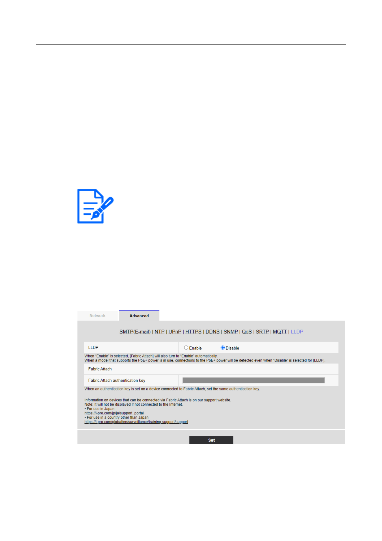
[Note:]
・The items that can be set differ depending on the function of the model.
・Refer to the catalog specifications for the functions installed in each model.
・[PTZ] [Auto track] can be set only for PTZ-cameras.
Prohibited Characters:One-byte symbol ¥
[QoS]
Select the level of QoS from 0, 1, or 2. 0<1<Communication quality is high with 2.
0:QoS0 delivers up to one message. Messages are not guaranteed to reach the server.
1:In QoS1, messages are delivered at least once. Messages are guaranteed to reach the
destination, but may be duplicated.
2:QoS2 delivers the message exactly once. Messages are guaranteed to arrive only once without
excess or deficiency.
[Retain]
Check this box to have the last notified message saved on the MQTT server.
16.2.11 Configure LLDP
This section configures the LLDP (Link Layer Discovery Protocol) function. Interoperation can be
realized by transmitting and receiving the device information of the camera with LLDP-compatible
devices.
[LLDP]
You can configure [On] and [Off] to enable the LLDP function and Fabric Attach.
[Enable]:Use the LLDP function.
16 Networking configuration [Network]
16.2 [Advanced] for advanced networking settings
529
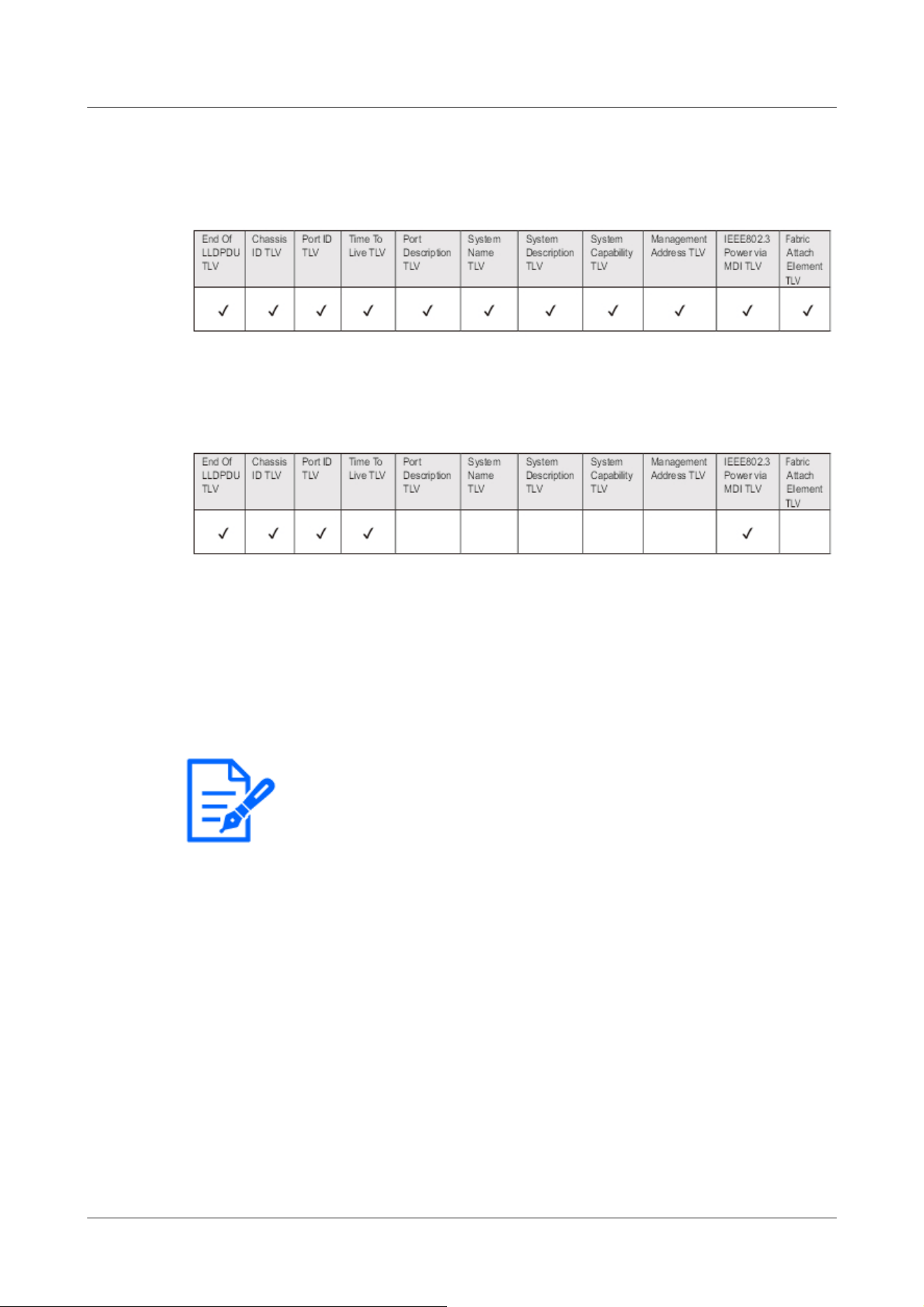
[Note:]
・Press [Set] to restart the computer. After restarting, the product cannot be
operated for about two minutes as it was when the power was turned on.
・Information on devices that can be connected via Fabric Attach can be found on
our technical information website.
[Disabled]:The LLDP function is not used.
When set to [On], LLDP is sent with TLVs checked in the following tables.
For the model supporting *PoE+ power supply, LLDP including TLV with checks in the following
table is sent for PoE+ power supply even if set to [Off].
Fabric Attach authentication key
Enter the key to be used for Fabric Attach authentication. It is valid only when [LLDP] is [On].
Number of characters that can be entered:0 to 32 characters (blank if not Fabric Attach
authentication)
Input Characters:One-byte alphanumeric characters
16.3 Setting up HTTPS
Here, you set up HTTPS to encrypt camera access and enhance communication security.
HTTPS can be configured using pre-installed certificates on the camera body or using CA (CA)
certificates obtained between the customer and the certification authority.
HTTPS setting method (pre-installation) is shown on the support video page of the support site.
<Control No. P0002>. Please refer to configure HTTPS (CA certificate)<Control No. P0003>.
16 Networking configuration [Network]
16.3 Setting up HTTPS
530
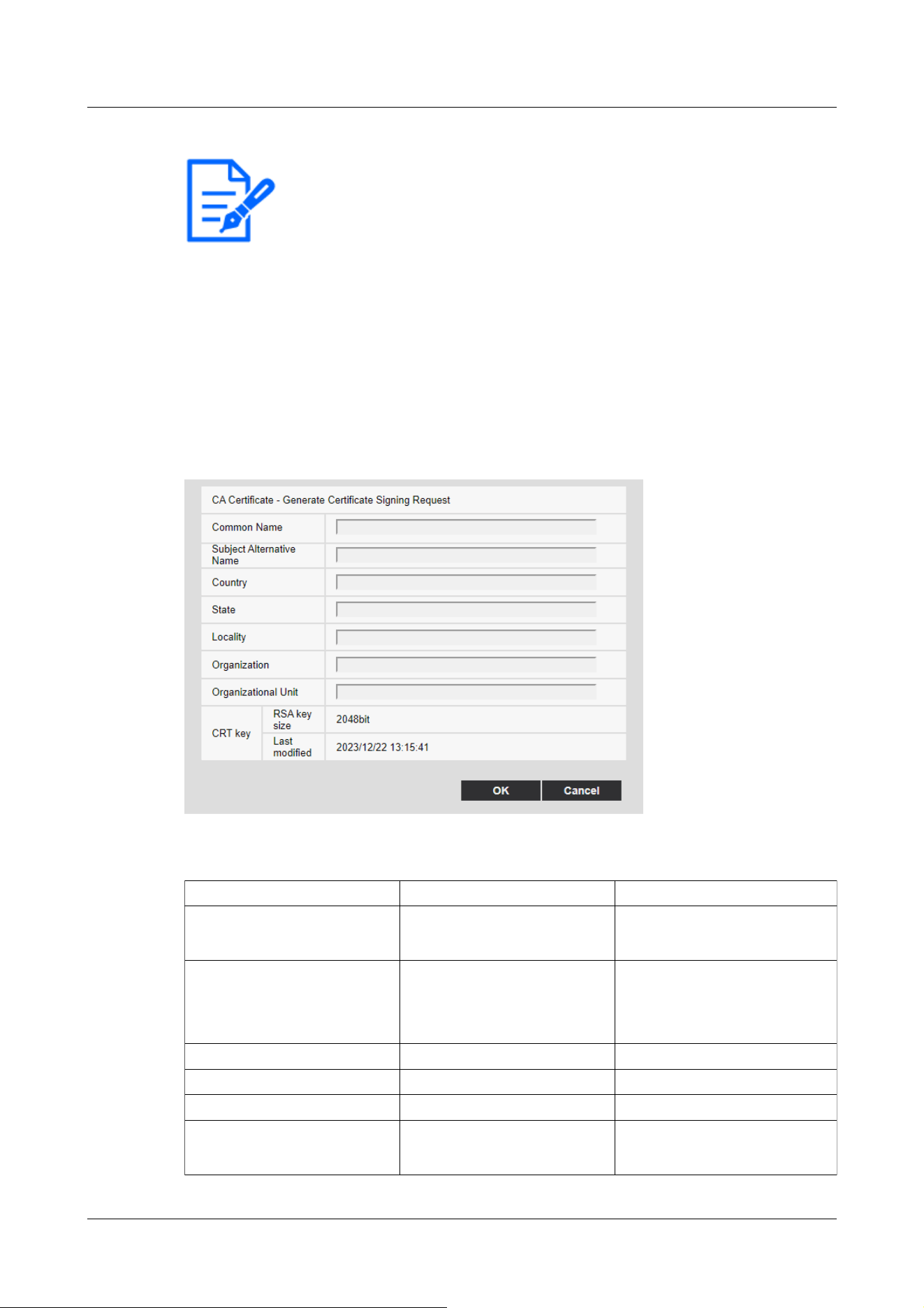
[Note:]
・[MULTI_PTZ] When the HTTPS connection is accessed, only the camera
accessed is protected.
・[Subject Alternative Name] can be set in [Signature Request (CSR) Generation
Dialog] in the software Ver.2.50. For details, please read the following.
→16.3.1 How to generate a signing request (CSR)
Item Explanation Available number of characters
[Host name] Enter the camera address or
the host name.
64 characters
[Subject Alternative Name] Enter the domain name. 64 characters per domain
Available number of domain
registration: 8
[Country] Enter the country code. 2 characters: Country code
[State] Enter the name of the state. 128 characters
[Locality] Enter the name of the locality. 128 characters
[Organization] Enter the name of the
organization.
64 characters
16.3.1 How to generate a signing request (CSR)
1 Click the [Execute] button in [CA Certificate - Generate Certificate Signing Request].
→ The “CA Certificate - Generate Certificate Signing Request” screen is displayed.
2 Enter the information for the certificate to be generated.
16 Networking configuration [Network]
16.3 Setting up HTTPS
531

Item Explanation Available number of characters
[Organizational Unit] Enter the name of the
organizational unit.
64 characters
[CRT key] Displays the key size of the
current CRT key and the
date/time it was generated.
-
[Note:]
・When using a CA certificate, make sure you enter the information that is
required by the certification authority you are applying to.
・For the [Host name], [State], [Locality], [Organization], and [Organizational
Unit], you can enter the following characters:
0 to 9, A to Z, a to z, and the following symbols:
- . _ , + / ( )
・For the [Subject Alternative Name], you can enter the following characters:
0 to 9, A to Z, a to z, and the following symbols:
. : * , -
・When entering multiple domain names in [Subject Alternative Name], separate
them with commas.
[Important]
・You must configure port forwarding for routers before using the DDNS service.
・About [Dynamic DNS (DDNS)] Update (RFC 2136)
We do not guarantee the operation of any DDNS services other than the
[Viewnetcam.com] service. Therefore, you are not liable for any failure or damage
caused by the use of DDNS services other than the [Viewnetcam.com] service.
For selection and configuration of DDNS services other than [Viewnetcam.com]
services, please contact the service provider.
16.4 How to configure DDNS
When using the DDNS function on your computer, you can use one of the following DDNS
services:
[Viewnetcam.com] services
Dynamic DNS Update (RFC 2136)
16 Networking configuration [Network]
16.4 How to configure DDNS
532

・Check the [Viewnetcam.com] service website for browsers supported by the
[Viewnetcam.com] service.
[Note:]
・The [Viewnetcam.com] service (fee-based) is the DDNS service we recommend.
For more information about the [Viewnetcam.com] service, refer to the
[Viewnetcam.com] Service website (http://www.viewnetcam.com/).
About DDNS Services (IPv4/IPv6)
You can view camera images via the Internet by using the DDNS service.
The DDNS service is a service that matches a domain name with a dynamically changing global
address. You can configure the [Viewnetcam.com] service (charged for IPv6, but both IPv4 and
IPv6 connections are required) or dynamic DNS Update (RFC2136 compliant) for DDNS services.
Since many providers provide services that change their global addresses rather than being fixed,
the camera may not be able to access the previous global addresses after a period of time. To
access cameras with non-fixed global addresses from the Internet, you must have one of the
following services:
DDNS services (e.g., [Viewnetcam.com] services)
This service can be accessed with a fixed registered domain name (e.g., ***
**.
miemasu.net) even if
the global address changes. You must also subscribe to domain name services when using IPv6
connections.
For more information about [Viewnetcam.com] Services, see the [Viewnetcam.com] website.
Fixed IP address service (e.g. service of subscription provider)
This service does not change the global address (fixed).
DDNS Service Mechanism (for [Viewnetcam.com] Service)
16 Networking configuration [Network]
16.4 How to configure DDNS
533
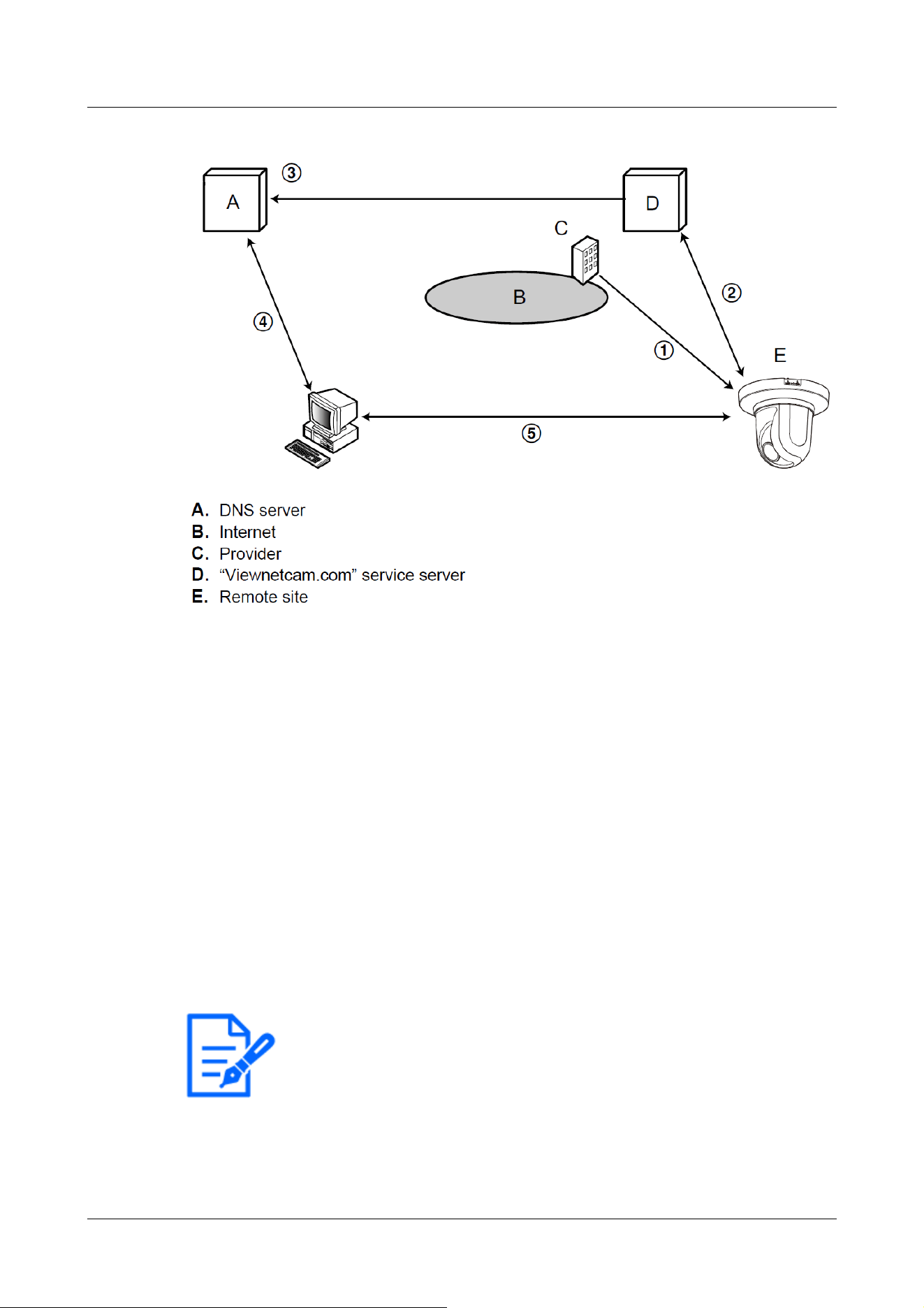
[Note:]
・Contact your provider to determine whether your IP address is fixed.
・Depending on the provider, local addresses may be assigned. In that case, the
DDNS service is not available. Please contact the provider you subscribe to.
① The contracted provider assigns a global address to the router (or camera). The global
address assigned at this time is not a fixed but a changing address.
②If you subscribe to [Viewnetcam.com] services, the cameras are assigned a unique [Domain
Name] (e.g., *****.miemasu.net). The camera manages the camera's domain name and the
global address of the router (or camera) by automatically notifying the [Viewnetcam.com]
service server of the router's (or camera's) global address (the [Viewnetcam.com] service
server).
③ The [Viewnetcam.com] service server registers the global addresses and domain names of
routers (or cameras) with the DNS server.
④ When accessing a camera via the Internet, the DNS server determines the global address of
the registered router (or camera) by entering the URL containing the domain name into the
Web browser.
⑤ You can access routers (or cameras) with an indexed global address to monitor the image.
16 Networking configuration [Network]
16.4 How to configure DDNS
534
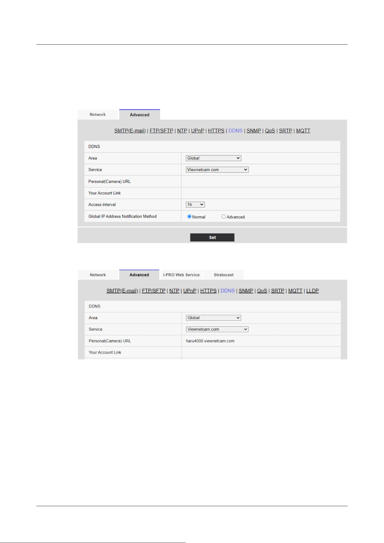
16.4.1 With [Viewnetcam.com] services
1 On the [Advanced] tab of the Network Page, select [DDNS], and then select [Japan] from the
[Area] tab.
2 Select [Viewnetcam.com] and press [Set].
3 Clicking on the URLs displayed on the [Link to MIEMASUNET registration] opens a new
window for registering [Viewnetcam.com] Services.
4 Register [Viewnetcam.com] Services according to the window. If the [Viewnetcam.com]
services registration window is not displayed, check that the PC is connected to the Internet
and press the Update browser button.
16 Networking configuration [Network]
16.4 How to configure DDNS
535
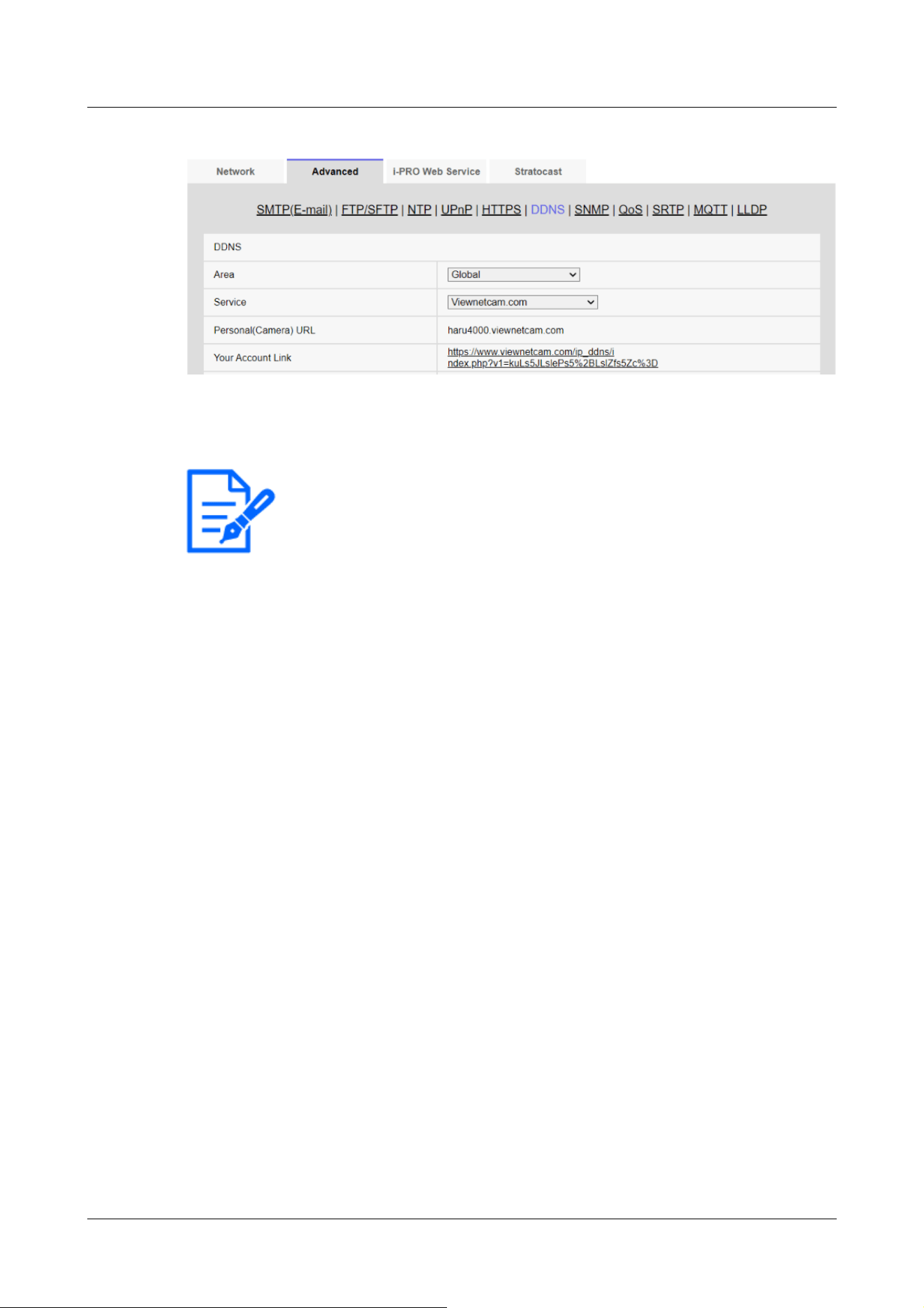
[Note:]
・The URLs of the registered cameras are displayed on the [Personal(Camera)
URL] when registration to the [Viewnetcam.com] services has been completed.
This address is used when accessing the camera via the Internet. It is recommended
that you register this URL as your favorite browser function. The camera's URLs
can also be viewed in the [Status] [Personal(Camera) URL] on the Camera
Maintenance page.
・The URLs of the cameras can be used after they are registered with the
[Viewnetcam.com] services. (It may take up to 30 minutes for the URL of the
registered camera to become valid.)
However, depending on the router, this URL cannot be accessed from a PC
connected to the same network (LAN) as the camera.
・If [Link to MIEMASUNET registration] is not displayed, make sure that you have
registered to [Viewnetcam.com] and that your PC is connected to the Internet,
and then press the Update browser button.
・If [User registered] is displayed in the [Viewnetcam.com] [Status] on the [Status]
tab of the Maintenance page, restart the camera after registering the
[Viewnetcam.com] service.
After restarting, make sure that the URLs registered in the [Viewnetcam.com]
[Personal(Camera) URL] are displayed in the [Status] tab on the Maintenance
page.
・The [Viewnetcam.com] service provides services other than dynamic DNS
services. For more information, refer to the [Viewnetcam.com] services website
(http://www.viewnetcam.com/).
5 Re-display the cameras and ensure that the [Personal(Camera) URL] shows the domains
(xxxx.miemasu.net:xxx) registered with the [Viewnetcam.com] services.
16 Networking configuration [Network]
16.4 How to configure DDNS
536
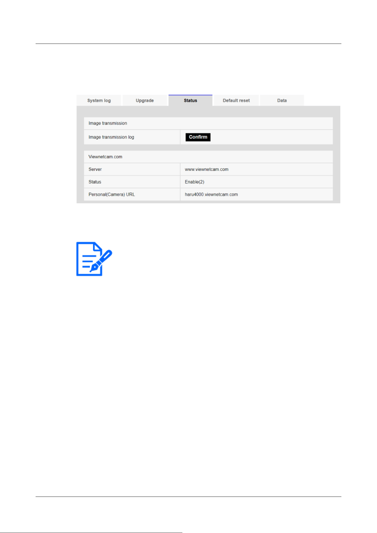
[Note:]
・If you see anything other than [Service contract is already registered.] in the
[Viewnetcam.com] [Status] on the [Status] tab of the Maintenance page, restart
the camera and re-access the screen.
Confirm the [Viewnetcam.com] services be registered
1 Click [Status] in the Maintenance page.
2 Ensure that [Service contract is already registered.] is displayed in the [Status] of the
[Viewnetcam.com] in the [Status] tabs on the Maintenance page.
Configure port forwarding without using UPnP
If you use a router that does not support UPnP, you must manually configure the port forwarding
feature for the router.
1 On the Network Page, press the [Network] tab.
2 In the [Network Settings], select [Static].
3 Check the IP address and port number displayed here, and make corrections if necessary.
(This is required when configuring port forwarding for routers.)
4 Press [Set].
5 Configure the port forwarding by referring to your router's instruction manual.
・Use the IP address and port number you checked in step 3 to configure.
・Port forwarding functions may be described as address translation, static IP mascalade,
virtual server, virtual server, or port mapping, depending on the router.
16 Networking configuration [Network]
16.4 How to configure DDNS
537

[Note:]
・Be sure to set [Auto port forwarding] to [Off] when configuring port forwarding
manually for routers.
[Note:]
・Contact your network administrator for the host name that is available.
[Note:]
・Contact your network administrator for the host name that is available.
16.4.2 Using Dynamic DNS Update (without DHCP)
[Host name]
Enter the host name to use for the dynamic DNS Update service.
Number of characters that can be entered:3 to 250 characters (host name). Enter in (domain
name) format
Input Characters:One-byte alphanumeric and one-byte symbols . ‑
[Access interval]
Select an interval to verify the IP address and host name for the dynamic DNS Update service
server from the following.
[10min]/ [20min]/ [30min]/ [40min]/ [50min]/ [1h]/ [6h]/ [24h]
16.4.3 Using Dynamic DNS Update
[Host name]
Enter the host name to use for the dynamic DNS Update service.
Number of characters that can be entered:3 to 250 characters (host name). Enter in (domain
name) format
Input Characters:One-byte alphanumeric and one-byte symbols . ‑
16 Networking configuration [Network]
16.4 How to configure DDNS
538

[Note:]
・If you use Remote Monitoring, Image capture size for stream (3) and stream (4) is
changed to VGA(640x360).
・Depending on the installed Extension software, internal memory used by Remote
Monitoring may be insufficient. Make sure that the remaining RAM space in
[Software mng.] tab. of Extension software is at least 15MB. If it is less than
15MB, Remote Monitoring does not operate normally.
・If you are using Remote Monitoring and have installed Extension software, make
sure that the remaining RAM is at least 15MB in [Software mng.] section of
Extension software section. If it is less than 15MB, Remote Monitoring does not
operate normally.
・If you plan to use Remote Monitoring and Extension software at the same time,
check to see if Extension software is available at the same time as Remote
Monitoring.
・If [Miemasu.net] servicing is enabled, Remote Monitoring is not available.
・[New X Fixed-8MP][New X Fixed-6M][New X Fixed-5M][AI Outdoor IR
BulletX-8M][AI Outdoor IR BulletX-5M] When [Image capture mode] is set to
[60fps Mode] or [50fps Mode], Remote Monitoring is not available.
16.5 Use Remote Monitoring
On the Network page, select [Remote Monitoring].
→5.1 How to display
→5.2 How to operate
Select this setting when connecting the camera directly to Remote Monitoring.
16 Networking configuration [Network]
16.5 Use Remote Monitoring
539
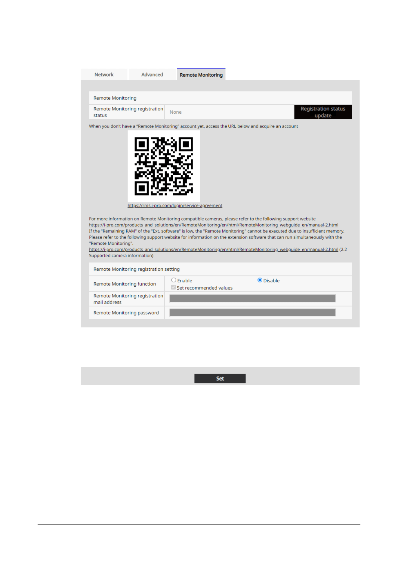
[Remote Monitoring function]
You can set the Remote Monitoring function (direct camera connection function) to Enable or
Disable.
When set to Enable, or if it is already enabled when the camera starts, it will connect to the
Remote Monitoring server (https://rms.i-pro.com).
This allows for video streaming to Remote Monitoring, playback and download of video data stored
on the SD card, and receiving alarm notifications.
16 Networking configuration [Network]
16.5 Use Remote Monitoring
540

[Note:]
・When you select [Set recommended values], the settings will be adjusted to
values suitable for Remote Monitoring connection, depending on the model.
・For details on the settings that will be adjusted when [Set recommended values]
is selected, refer to the following link.
CameraDirect-RemoteMonitoring_webguide_en
[Remote Monitoring registration mail address]
The input field becomes available when you select [Enable] for the [Remote Monitoring function].
Before doing this, you need to access Remote Monitoring (https://rms.i-pro.com) to register
your email address and set a password. Enter the email address here that you registered in
Remote Monitoring.
[Remote Monitoring password]
The input field becomes available when you select [Enable] for the [Remote Monitoring function].
Before doing this, you need to access Remote Monitoring (https://rms.i-pro.com) to register
your email address and set a password. Enter the password here that you registered in Remote
Monitoring.
Setting up a direct camera connection
1 Select [Enable] for the [Remote Monitoring function] and enter your email address and
password.
16 Networking configuration [Network]
16.5 Use Remote Monitoring
541
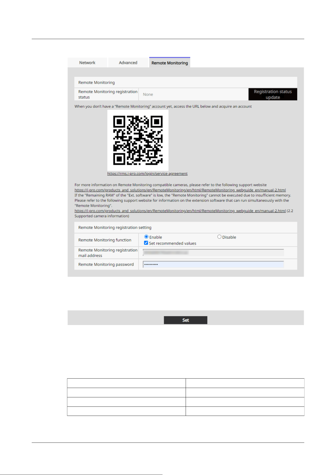
Item Remote Monitoring Enabled
Audio out Audio
SD Memory Card File System Format FAT(FAT16/FAT32/exFAT)
Recording stream Stream(1)
2 Click the [Set] button.
Check the alert message and click the OK button.
When [Remote Monitoring function] is set to [Enable], the settings in the following table will
be adjusted and fixed, regardless or whether or not the checkbox is selected.
16 Networking configuration [Network]
16.5 Use Remote Monitoring
542
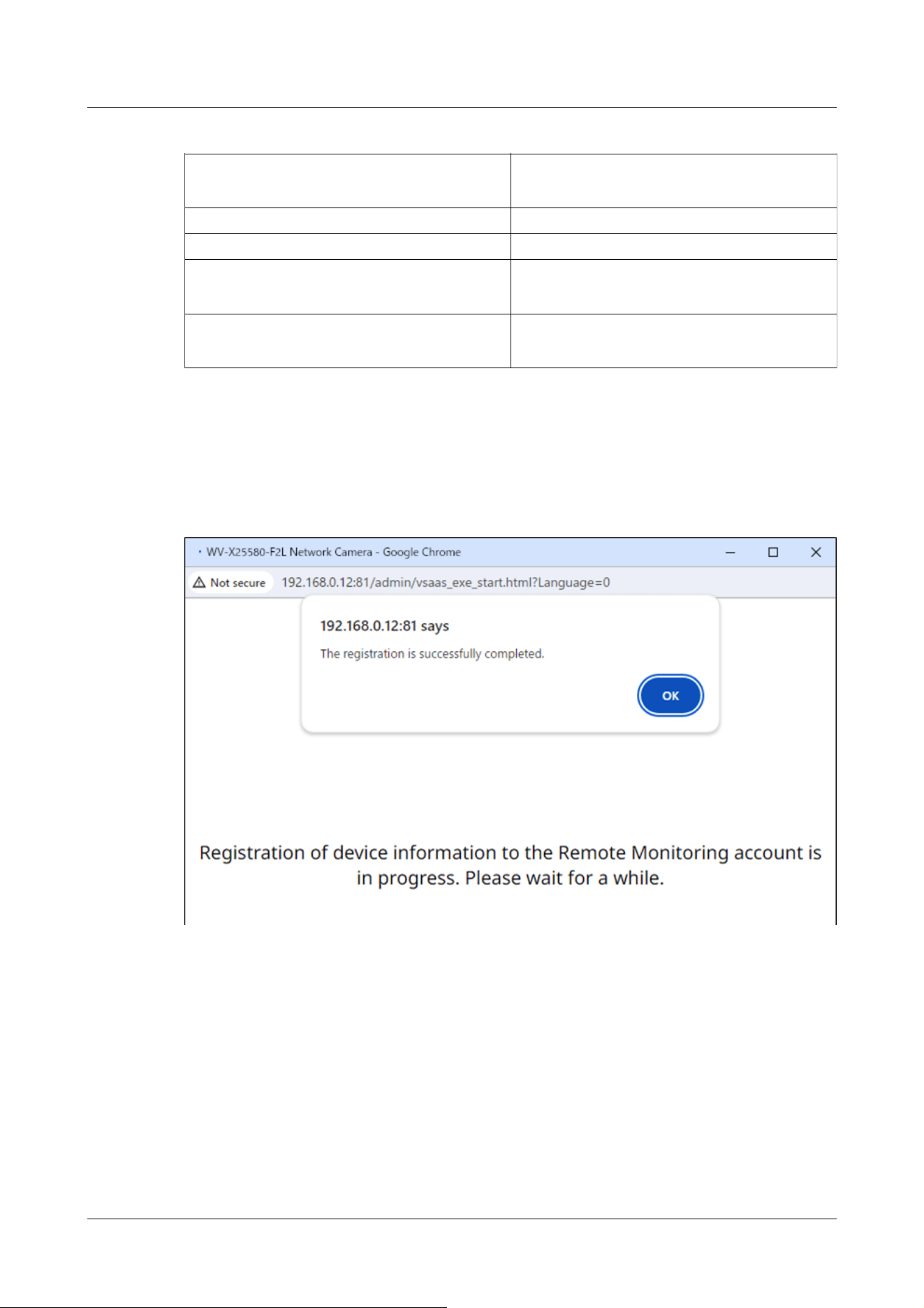
Image capture size of JPEG(1)
If [Image capture mode] is [16:9 mode]: 640x360
If [Image capture mode] is [4:3 mode]: VGA
Stream transmission of Stream(1), Stream(2) On
Stream encoding format of Stream(1), Stream(2) H.265
Image capture size of Stream(4)
If [Image capture mode] is [16:9 mode]: 640x360
If [Image capture mode] is [4:3 mode]: VGA
TCP alarm notification, Additional extended
alarm information
On
3 Registration complete
A popup window is displayed. The registration process takes approximately 20 seconds.
Once registration is complete, [The registration is successfully completed.] is displayed, and
[Remote Monitoring registration status] will show either [Registered (No license is allocated)]
or [Registered (License is allocated)].
If the popup is not displayed
If popups are blocked, a notification is displayed in the address bar indicating that the popup was
blocked. Allow popups to be displayed. Once this is done, set the [Remote Monitoring function] to
[Disable], then switch it back to [Enable], enter your email address and password, and then click
the [Set] button.
16 Networking configuration [Network]
16.5 Use Remote Monitoring
543
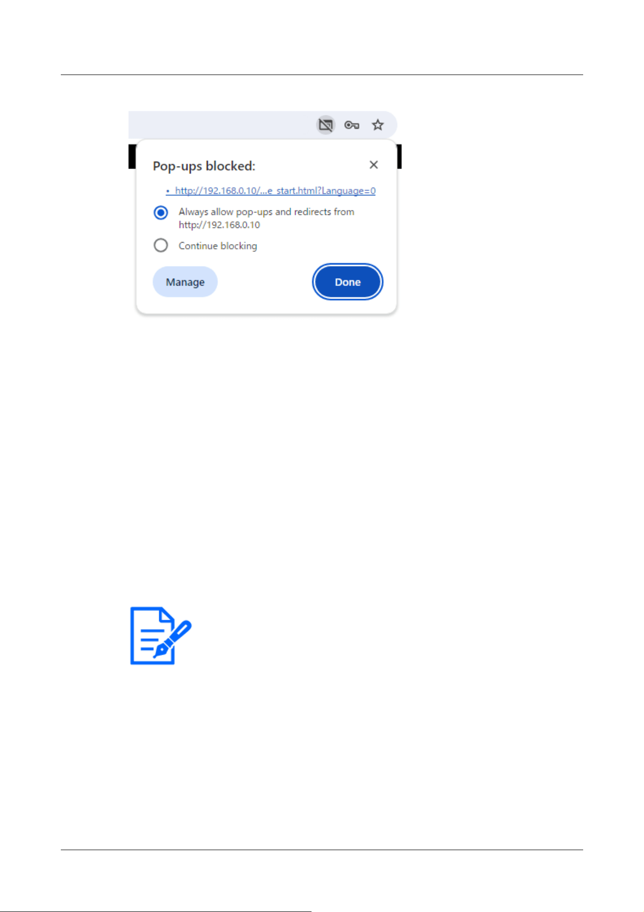
[Note:]
・For more information about the Remote monitoring supported models, refer to
our technical information website <Control No.:C0103>.
When registration is complete, close the popup by clicking the [x] at the top-right. Next, click the
[Registration status update] button to confirm that [Remote Monitoring registration status] shows
either [Registered (License is allocated)] or [Registered (No license is allocated)].
Correcting an incorrectly entered email address or password
Set the [Remote Monitoring function] to [Disable], then switch it back to [Enable], enter the
correct email address and password, and then click the [Set] button.
If registration fails
・Check that the network camera is connected to allows external connections.
・Check that the default gateway is set correctly in the [Network] settings.
・Check that the primary server address is set correctly if DNS is set to Manual in the [Network]
settings.
・Check that the date and time in the [Basic] settings match the local standard time for the
camera's location.
Remote Monitoring supported browser
Use Google Chrome or Microsoft Edge to access the system. Firefox may not operate correctly.
16 Networking configuration [Network]
16.5 Use Remote Monitoring
544

[Note:]
・The items that can be set differ depending on the function of the model.
・Refer to the catalog specifications for the functions installed in each model.
・[PTZ] Only PTZ cameras can be set for position refresh, automatic tracking start
permission, auto pan, patrol, and preset sequence.
17 [Schedule] for scheduling
The Schedule page sets up schedules for the following items:
・Alarm input permission (Terminals 1, 2 and 3)
・Alarm input permission (terminal 1)
・Alarm input permission (terminal 2)
・Alarm input permission (terminal 3)
・Operation detection permission
・Permission to detect disturbance
・Sound detection permission
・Impact detection permission
・Opening detection permission
・Image disclosure permission
・SD recording
・Scene file
・Regular transmission of FTP/SFTP
・Permission to send mail
・Position refresh
・Preset position (1 to 256)
・Auto tracking start permission
・Auto pan
・Patrol
・Preset sequence
・All alarms detection permission (when visible net is set and schedule 8 only)
・<Auto Schedule>Daytime: Image Quality1 / Night: Image Quality 2(Schedule 1 only)
・Restart the camera (Schedule 8 only)
Schedule pages consist of [Schedule] tabs only. Up to 8 schedules can be set.
1 From the [Operation mode], select Scheduling operation.
17 [Schedule] for scheduling
545

The default setting is [Off].
[Off]:Schedule operation is not executed.
[Alarm permission(Terminal alarm 1,2,3)]:Allows the alarm input of the terminal while the
schedule is being set.
[Alarm permission(Terminal alarm 1)]:The alarm input of terminal 1 is enabled while the
schedule is set.
[Alarm permission(Terminal alarm 2)]:Allows alarm input of terminal 2 while schedule is set.
[Alarm permission(Terminal alarm 3)]:Allows alarm input of terminal 3 while schedule is set.
[VMD permission]:Operation detection is enabled while the schedule is set.
[SCD permission]:Permits disturbance detection while scheduled.
[Audio detection permission]:During scheduling, sound detection is enabled.
[Impact detection permission]:During scheduling, impact detection is enabled.
[Casing open detection permission]:During scheduling, opening detection is enabled.
[Access permission]:Images are prohibited from being viewed by users with [2. Camera
control] or [3. Live view] access levels set in the [User auth.] tabs, except when scheduled.
→15.1 [User auth.] to configure user-authentication
[SD memory recording]:When the scheduled time is reached, SD recording set by [Recording
stream] is executed. It is valid only when [Recording format] is streamed.
[All detect permission]:If [DDNS] is set to [Viewnetcam.com], only Schedule 8 can be
selected. All alarm inputs are allowed while the schedule is set. [Sun] and [24h] are
automatically set from [Mon] and cannot be changed.
[Image quality 1]:Scene1 (Scene File 1): When the scheduled time is reached, the image
quality is set to [Scene File 1]. When the scheduled time is over, the [Scene file is not
applied] image quality is set.
[Image quality 2]:Scene2 (Scene File 2): When the scheduled time is reached, the image
quality is set to [Scene File 2]. When the scheduled time is over, the [Scene file is not
applied] image quality is set.
[Image quality 3]:Scene3 (Scene File 3): When the scheduled time is reached, the image
quality is set to [Scene File 3]. When the scheduled time is over, the [Scene file is not
applied] image quality is set.
[Image quality 4]:Scene4 (Scene File 4): When the scheduled time is reached, the image
quality is set to [Scene File 4]. When the scheduled time is over, the [Scene file is not
applied] image quality is set.
[FTP/SFTP periodic image transmission]:When the scheduled time is reached, FTP/SFTP
periodic transmission is executed.
[E-mail permission]:Mail notification is executed when an alarm is generated while the
17 [Schedule] for scheduling
546

[Note:]
・When using [Access permission], set [User auth.] to [On] on the [User auth.] tab
and [Host auth.] to [Off] on the [Host auth.] tab.
→15.1 [User auth.] to configure user-authentication
.
.
]
schedule is set.
[Reboot]:When the scheduled time is reached, the camera restarts. Only available in
Schedule 8.
[Position refresh]:The position is refreshed when the scheduled time is reached.
1~256:When the scheduled time is reached, the preset position is moved from the preset
position registered beforehand to the selected position.
[Auto track permission]:Allows the auto-tracking setting set on the [Auto track setting] tab
while scheduling.
[Auto pan]:When the scheduled time is reached, the auto pan operation set in the [Position]
tab starts.
[Patrol 1]:When the scheduled time is reached, Patrol 1, which is set in the [Position] tab,
starts. It is valid only when [Patrol 1] is set.
[Patrol 2]:When the scheduled time is reached, Patrol 2 set in the [Position] tab starts. It is
valid only when [Patrol 2] is set.
[Patrol 3]:When the scheduled time is reached, Patrol 3, which is set in the [Position] tab,
starts. It is valid only when [Patrol 3] is set.
[Patrol 4]:When the scheduled time is reached, Patrol 4, which is set in the [Position] tab,
starts. It is valid only when [Patrol 4] is set.
[Preset sequence(Preset sequence 1)]:When the scheduled time is reached, preset
Sequence(preset Sequence 1) set in the [Position] tab starts. It is valid only when [Preset
sequence(Preset sequence 1)] is set.
[Preset sequence 2]:When the scheduled time is reached, preset Sequence 2 set in the
[Position] tab starts. It is valid only when [Preset sequence 2] is set.
[Preset sequence 3]:When the scheduled time is reached, the preset sequence 3 set in the
[Position] tab starts operation. It is valid only when [Preset sequence 3] is set.
[<Automatic schedule> Daytime: Image Quality 1 / Night: Image Quality 2]: At sunrise, the
image quality is set to [Scene file 1], and at sunset, the image quality is set to [Scene file 2].
Only schedule 1 can be selected. This cannot be selected if the sunrise/sunset times have
not been set. Please refer to the following for the setting method.
→17.3 How to change the image quality based on the time of sunrise/sunset
2 Checks the Day of the week boxes in which you want to schedule in [Schedule].
17 [Schedule] for scheduling
547

→15.2 [Host auth.] to configure host-authentication
・If you want to use [SD memory recording], set [Recording format] in the [SD
memory card] tabs to streams and set [Save trigger] to [Schedule].
・Schedule 1 [<Automatic schedule> Daytime: Image Quality 1/ Night: Image
Quality 2] and Schedules 2 to 8 [Image Quality 1: Scene 1 (Scene file 1)], [Image
Quality 2: Scene 2 (Scene file 2)], [Image Quality 3: Scene 3 (Scene file 3)], and
[Image Quality 4: Scene 4 (Scene file 4)] cannot be selected at the same time.
[Note:]
・[PTZ] When you configure the [Auto pan] [Patrol] [Preset sequence], make sure
that the times do not overlap.
・If [<Auto Schedule> Daytime: Image Quality 1/ Night: Image Quality 2] is
selected in Schedule 1, the time zone setting will be disabled.
3 To specify the time, click [▼] to set the time. Select [24h] when no time zone is set.
4 When [Set] is clicked after the setting is finished, the settings are displayed at the bottom of
the window.
17 [Schedule] for scheduling
548
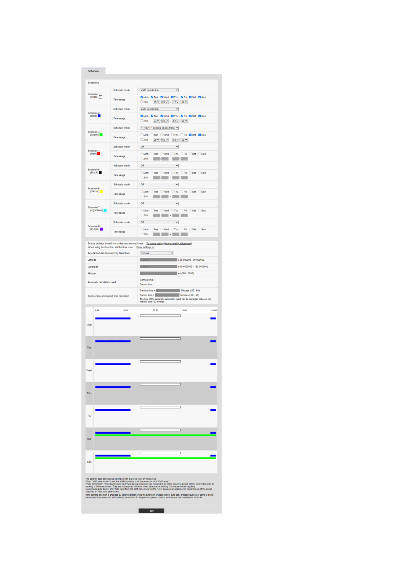
17 [Schedule] for scheduling
549

[Note:]
・The colors displayed on Schedules 1 to 8 represent the colors of the lines
displayed in the Schedule field at the bottom of the screen.
・If position refresh and image quality set time are set at the same time, the image
quality is reflected after position refresh is completed.
・When the operation modes of Schedules 1 to 8 are set to [Off], the following
items are permissible.
Alarm input permission (terminals 1, 2 and 3)
Alarm input permission (terminal 1)
Alarm input permission (terminal 2)
Alarm input permission (terminal 3)
Operation detection permission
Obstruction Detection Permission
-Sound detection permission
-Impact detection permission
-Opening detection permission
-Image disclosure permission
-All alarm detection permission (when visible net is set and schedule 8 only)
17 [Schedule] for scheduling
550
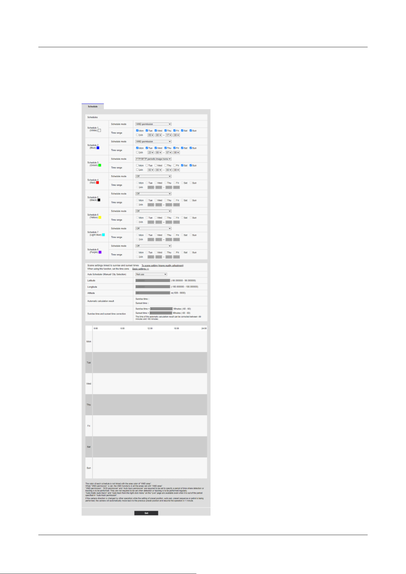
17.1 How to set the schedule
17 [Schedule] for scheduling
17.1 How to set the schedule
551

4 In [Schedule], tick the Day of the week boxes in which you want to schedule.
The day of the week is enabled.
5 To specify the time, click [▼] to specify the time.
If you do not specify a time zone, tick [24h].
6 When you are finished, press [Set].
The contents set at the bottom of the screen are displayed.
17 [Schedule] for scheduling
17.1 How to set the schedule
552

17 [Schedule] for scheduling
17.1 How to set the schedule
553

17.2 How to Delete Schedule
1 Uncheck the Day of the week box in which you want to delete the schedule.
2 When you are finished, press [Set].
The schedule for the selected day of the week is deleted.
17 [Schedule] for scheduling
17.2 How to Delete Schedule
554
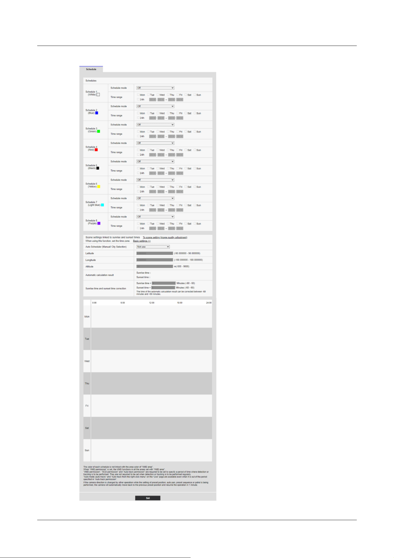
17 [Schedule] for scheduling
17.2 How to Delete Schedule
555

17.3 How to change the image quality based on the time of
sunrise/sunset
1 You can set the time of Sunrise and Sunrise from [Set scenes linked to Sunrise and Sunrise
time].
[To scene setting (image quality adjustment)]
This is a link to the image quality adjustment for scene setting.
[Basic settings]
This is a link to the basic settings for setting the time zone.
[Auto Scheduler (Manual/City Selection)]
Select the input method for [Latitude], [Longitude], and [Altitude].
[Not used]:Disable operation mode [<Auto Schedule> Daytime: Image Quality 1 / Night: Image
Quality 2].
[Manual]:Manually enter [Latitude], [Longitude], and [Altitude].
[(City name)]:Displays a list of cities. The [Latitude], [Longitude], and [Altitude] of the selected
city are entered and used for [Automatic calculation result].
[Latitude]
Enter the latitude of the region of the camera you are using.
Input range: -180 to 180 (valid up to 6 decimal places)
[Longitude]
Enter the longitude of the region of the camera you are using.
Input range: -90 to 90 (valid up to 6 decimal places)
[Altitude]
Enter the altitude of the region of the camera you are using.
If left blank, it will be calculated as “10m”.
Input range: -500 to 9000 (m)
[Automatic calculation result]
The sunrise/sunset time is calculated from [Latitude], [Longitude], and [Altitude].
If you do not click the [Set] button, the calculation result will not be applied.
[Sunrise time and sunset time correction]
Perform time correction on the sunrise/sunset times in [Automatic calculation result] to
determine the time applied for the image quality.
Input range: -60 to 60 (minutes)
2 Click the [Set] button.
17 [Schedule] for scheduling
17.3 How to change the image quality based on the time of sunrise/sunset
556


[Note:]
・The items that can be set differ depending on the function of the model.
・Refer to the catalog specifications for the functions installed in each model.
18 [Maintenance] to maintain the machine
The Maintenance page checks the system log, software upgrades, checks the status, and
initializes the computer.
The Maintenance page consists of the [System log], [Upgrade], [Status], [Default reset], and
[Data] tabs.
18.1 [System log] to check the system logs
Click [System log] in the Maintenance page. Refer to the following how to display and operate the
Advanced menu.
→5.1 How to display
→5.2 How to operate
If [SD memory card] is set to [Use] and an SD Memory Card is installed on your computer, up to
4000 system logs can be saved in the SD Memory Card.
→9.2 [SD memory card] for setting SD Memory Cards
If [SD memory card] is set to [Not use], up to 100 system logs can be saved in the computer's
internal memory.
If the maximum number of system logs that can be saved is exceeded, the log is overwritten from
the old log.
100 system logs are displayed and the logs are saved even if the camera is turned off.
[<<Latest 100 items
Click to display the list of the latest 100 system logs.
Next 100 items>>]
Click to display the following 100 items in the displayed system log list.
18 [Maintenance] to maintain the machine
18.1 [System log] to check the system logs
558

[Note:]
・If [Time display format] is set to [24h], the logging date and time will be displayed
in 24-hour format.
[Page number display]
The currently open page is displayed in the form [Page/Total Page].
[<<Previous 100 items
Click to display 100 items in front of the displayed system log.
[No]
The serial number in the system log is displayed.
[Time & date]
The date and time when the log occurred is displayed.
[Description]
The contents of the system log are displayed.
For details on the contents of each system log, refer to the following.
→20.1 System Log Display
18.2 [Upgrade] to upgrade the software
Click [Upgrade] in the Maintenance page. Refer to the following how to display and operate the
Advanced menu.
→5.1 How to display
→5.2 How to operate
Here, you can review the software version and update the software to the latest version.
Contact your dealer for software for upgrading.
[Model no.], [MAC address], [Serial no.], [Firmware version], [IP address(IPv6)], [Time past from
the date of manufacture]
Individual information on the computer is displayed.
18 [Maintenance] to maintain the machine
18.2 [Upgrade] to upgrade the software
559
[Note:]
・[MULTI_PTZ] [MAC address], [Firmware version], and [IP address(IPv6)] of the
PTZ camera and Multi-directional camera are displayed.
[Important]
・Do not use space or double-byte characters in the save directory.
[Note:]
・The latest version of the software is available on our technical information website.
https://i-pro.com/products_and_solutions/en/surveillance/documentation-
database
[Note:]
・Note that the set data cannot be restored after initialization.
[Important]
・After upgrading, be sure to check the version on this page.
・After upgrading, be sure to delete the temporary Internet file.
→20.2 Trouble!?
・Use a PC on the same subnet as the machine to upgrade the version.
・When using the version upgrade software, be sure to check the precautions at
the dealer where you purchased the software and follow the instructions.
・Use our specified img file for the software to be used to upgrade the version.
Be sure to use [Model name _xxxxx.img] (model name is lowercase and [WV-] is
not required) as the file name of the software to be used for version upgrading.
]
.
1Contact your dealer and download the latest software to the hard disk of your PC.
2Click [Select File] to specify the software that was downloaded.
3Click the radio button to select whether to initialize the data after the version upgrade has been
completed.
4Press [Execute].
The confirmation screen for executing the version upgrade is displayed.
18 [Maintenance] to maintain the machine
18.2 [Upgrade] to upgrade the software
560

*[xxxxxx] contains the software version.
・Do not turn off the computer during version upgrading.
・Do not perform any operation during version upgrading until the version upgrade
is completed.
・The following data will not be initialized even if [Initialize setup data after version
upgrade is completed] is selected.
IPv4 DNS primary server address, secondary server address, IPv6 primary server
address, DNS secondary server address, DHCP On/Off, IP address, subnet mask,
default gateway, HTTP port, HTTPS port, HTTP/HTTPS connection method,
CRT key, CA certificate, UPnP setting, communication rate, delivery rate control
(bit rate), time setting, IEEE802.1X setting, function extension software, and
function extension software setting
[Note:]
・Please refer to our technical information website <Control No. C0111> for the
contents of the status display.
18.3 [Status] for checking the status
Click [Status] in the Maintenance page. Refer to the following how to display and operate the
Advanced menu.
→5.1 How to display
→5.2 How to operate
Here, you can check the status of the machine.
[Viewnetcam.com]
[Server]
The URLs for the [Viewnetcam.com] services server are displayed.
[Status]
This box indicates the registered status of [Viewnetcam.com] services.
[Personal(Camera) URL]
The URLs of cameras registered for the [Viewnetcam.com] services are displayed.
18 [Maintenance] to maintain the machine
18.3 [Status] for checking the status
561

Image transmission
[Image transmission log]
Click the [Confirm] button, to display the image transmission log in a separate window.
If [SD memory card] is set to [Use] and an SD Memory Card is installed on your computer, up to
4000 image transmission logs can be saved in the SD Memory Card.
→9.2 [SD memory card] for setting SD Memory Cards
If [SD memory card] is set to [Not use], up to 200 image transmission logs can be saved in the
computer's internal memory.
If the maximum number of image transmission logs that can be saved is exceeded, the log is
overwritten from the old log.
100 image transmission logs are displayed and the logs are saved even if the camera is turned off.
[<<Latest 100 items
Click to display the list of the latest 100 image transmission logs.
Next 100 items>>]
Click to display the following 100 items in the displayed image transmission log list.
[Page number display]
The currently open page is displayed in the form [Page/Total Page].
[<<Previous 100 items
Click to display 100 items in front of the displayed image transmission log.
[No]
The serial number in the image transmission log is displayed.
[Time]
Time and date at the error occurrence will be displayed.
[Stream type]
The stream type (Stream(*), JPEG(*), SD memory card playback) of the image transmission logs
will be displayed.
(*) displays the number.
[Connected user]
18 [Maintenance] to maintain the machine
18.3 [Status] for checking the status
562

[Note:]
・If [Off] is selected for [User auth.], [-] will be displayed.
[Note:]
・A stop request may not be logged in the following cases.
- When settings related to the stream are changed, such as the image mode,
stream, or resolution
- When moving to the setting screen from the Live image
- When the Live image is closed
- When the network is disconnected
The user of the image transmission will be displayed.
[IP address]
The IP address of the image transmission will be displayed.
[Event]
Start requests, stop requests, and start errors (heavy access) of the image transmission will be
displayed.
Power Usage
[Power Monitor]
Click the [Confirm] button, to display the Power Monitor window.
On the Power Monitor screen, you can see the transition of power consumption on the graph.
[Power supply in use]
The camera's power source is displayed.
[Current Power Usage]
Displays current power usage.
[Average power consumption during the period]
The average value of the power displayed in the graph is displayed.
[Maximum power consumption during the period]
The maximum value of the power displayed in the graph is displayed.
18 [Maintenance] to maintain the machine
18.3 [Status] for checking the status
563

[Note:]
・When you move the cursor to a point in the graph, the measured time and power
used are displayed.
[Note:]
・If you set [Viewnetcam.com] in [DDNS] on the [Advanced] tab of the Network
Page, the Network status is displayed.
[Display period]
Select the time period displayed in the graph from the pull-down menu.
[30min]/ [1h]/ [24h]/ [1week]/ [1month]
Clicking [Update] button refreshes the power monitoring window.
UPnP
Port number (HTTP), port number (HTTPS)
The port number configured for port forwarding in UPnP is displayed.
[Status]
The state of the port forwarding is displayed.
[Router global address]
The global address of the router is displayed.
[Self check]
The hardware self-diagnosis results are displayed.
[Operation information]
[Number of times of pan/tilt operation]
The number of PAN and TILT operations and the last replacement time are displayed.
Press the [Execute] button of the [Reset at the time of replacement] button to change the
operation count to zero and the last replacement time is updated.
[Number of times of zoom/focus operation]
The number of ZOOM and FOCUS operations and the last replacement time are displayed.
Press the [Execute] button of the [Reset at the time of replacement] button to change the
operation count to zero and the last replacement time is updated.
[Status]
The number of starts, energizing time, temperature sensor information, heater information, etc.
are displayed.
18 [Maintenance] to maintain the machine
18.3 [Status] for checking the status
564

[Note:]
・[PTZ] All [Hardware information] are displayed.
・[AI Outdoor IR Bullet] [Hardware information] is displayed only in [Number of
times of zoom/focus operation].
[Note:]
・[Rapid PTZ] [Active ClearSight] will appear only in Rapid PTZ Camera. Images
may be distorted during [Active ClearSight] operation.
[Note:]
・Only the models that the USB adapter can connect to are displayed.
・Refer to the catalog specifications for the functions installed in each model.
Active ClearSight
[Active ClearSight]
Press the [Execute] button to operate the camera at high speed to remove adhered water droplets.
USB interface
[Status]
If you recognize that the Wi-Fi USB adapter for installation is connected to the USB port, the
Wi-Fi USB adapter part number information is displayed. If it is not recognized, [Not use] is
displayed.
[Disable]
To disable the Wi-Fi USB adapter for installation, press [Execute].
If you want to recognize the Wi-Fi USB adapter again, use the INITIAL SET button.
Initialize (refer to the WEB Guide for instructions on how to initialize using the INITIAL SET
button).
SD Memory Card
[Model no.]
Displays the model number of the SD memory card. If the product number data acquisition fails,
[Read error] is displayed. When the SD Memory Card is not used, [Not use] is displayed.
Otherwise, [Unknown] is displayed.
[Serial no.]
Displays the SD Memory Card serial number. If the serial number is not obtained, [Unknown] is
displayed.
[Remaining capacity]
18 [Maintenance] to maintain the machine
18.3 [Status] for checking the status
565

[Note:]
・The number of times of overwriting is an estimate calculated in the computer and
may differ from the actual number of times of overwriting.
・If you use [SD memory card password lock] and the passwords of SD cards do not
match, the above information will not be displayed.
Classificat
ion
Form of label Details of contents
SD
Memory
Card
<SD>Format The SD Memory Card was successfully
formatted.
<SD>Format error An error occurred in the SD Memory Card
format.
<SD>Recognition error The SD Memory Card cannot be recognized
correctly.
<SD>Write error An error occurred during write processing of
the SD memory card.
<SD>Read error An error occurred during read processing of the
SD Memory Card.
<SD>Deletion error An error occurred during deletion processing of
the SD Memory Card.
<SD>Files system error An error occurred in the file system of the SD
Memory Card.
<SD>Other errors Other errors have occurred on the SD Memory
Card.
Displays the remaining capacity and total capacity of the SD Memory Card. The [SD memory
card] tab-SD Memory Card info [Remaining capacity] on the Basic Page and the displayed content
are the same.
[Total use time]
Displays the energizing time of the machine with the SD Memory Card inserted. If it fails to
acquire the operating hours, [Unknown] is displayed. The operating time is updated once an hour.
[Number of overwrite times]
Displays the total capacity of the SD Memory Card, the number of files written to the SD Memory
Card by the camera, and the number of times of overwriting calculated from the file size. If the
overwrite count fails, [Unknown] is displayed.
[No.] [Time & date] [Description] of logs
Displays the SD Memory Card log.
18 [Maintenance] to maintain the machine
18.3 [Status] for checking the status
566

<SD>The SD Memory Card recording
continuity is wrong. Check the
recording bit rate setting on the SD
Memory Card.
Data is missing during write processing on the
SD Memory Card.
<SD>An error occurs in the SD
Memory Card. Check the SD Memory
Card status.
Data is continuously missing during write
processing on the SD Memory Card. Confirm
that the SD Memory Card is correctly
recognized. If not, restart the computer or
unplug the SD Memory Card and insert it again.
[Important]
・To use this function correctly, format the SD Memory Card on your computer
before using the SD Memory Card.
・The correct information may not be displayed on the SD Memory Card used on a
computer other than this unit.
・Up to 30 SD Memory Card logs can be saved in the internal memory of this
computer. If the maximum number of system logs that can be saved is exceeded,
the log is overwritten from the old log.
[Note:]
・The wiper motor and wiper rubber counters are updated once every 2 hours.
Wiper counter
[Wiper motor counter]
The number of Wiper motor operations is displayed.
[Wiper rubber]
The number of Wiper rubber operations, exchange guideline and the last replacement time are
displayed.
Press the [Execute] button of the [Reset at the time of replacement] button to change the
operation count to zero and the last replacement time is updated.
18.4 [Default reset] to initialize and restart the computer
Click [Default reset] in the Maintenance page. Refer to the following how to display and operate
18 [Maintenance] to maintain the machine
18.4 [Default reset] to initialize and restart the computer
567

[Important]
・If you install the camera, the camera may be turned by mistake. When registering
a preset after installation, it is recommended to perform position refresh.
[Note:]
・Please refer to the following for the network settings. Refer to the WEB Guide for
the formatting method.
→16.1 Networking [Network]
the Advanced menu.
→5.1 How to display
→5.2 How to operate
Here, initialize the computer's setup data and restart the computer.
[Reset to the default(Except the network settings)]
When [Execute] is clicked, the computer settings are reset to default settings. However, the
network-related settings are not initialized.
When the initialization operation is performed, the product cannot be operated for approximately
3 minutes.
[Load the default HTML files (setup menu).]
[Execute] returns HTML files to their defaults.
When the initialization operation is performed, the product cannot be operated for approximately
3 minutes.
[Reset to the default and load the default HTML files.]
Press [Execute] to reset the computer settings and HTML files to their default settings. However,
the network-related settings are not initialized.
When the initialization operation is performed, the product cannot be operated for approximately
3 minutes.
[Reboot]
Press [Execute] to restart the computer. After restarting, the product cannot be operated for
about two minutes as it was when the power was turned on.
[Position refresh]
Refresh the machine position. The position can be corrected if the camera is misaligned with the
home position or preset position while the camera is in use or if the camera is misdirected while
the camera is powered on.
When position refresh is performed, operation cannot be performed for approximately 2 minutes.
18 [Maintenance] to maintain the machine
18.4 [Default reset] to initialize and restart the computer
568

・When you select Alarm or Mail Notification function, if the SD Memory Card is
not installed after restarting, you can notify the set [Destination E-mail address]
or [Destination of notification].
→16.2.1 Set mail sending
→14.12 [Notification] to set alarm notification
[Important]
・It takes a long time to create a backup file when backing up configuration data
and logs.
・If the backup operation takes more than 10 minutes, a communication timeout
may occur. At this time, the backup data may not have been obtained completely,
so please complete it within 10 minutes. You can also check whether the correct
data was obtained by restoring the acquired data. (excluding log data)
18.5 [Data] to back up/restore configuration logs
Click [Data] in the Maintenance page. Refer to the following how to display and operate the
Advanced menu.
→5.1 How to display
→5.2 How to operate
Here, you can back up/restore your computer's setup data, scene files, and save your log.
Backup
[Setup data(Setup data(Camera))]
You can back up the computer's settings to your computer by clicking [Execute].
[Setup data(AI-VMD)]
You can back up the AI-VMD's settings to your computer by clicking [Execute].
[Scene file]
By clicking on [Execute], you can back up the scene file settings for your computer.
[Logs]
You can back up your computer's logs by clicking [Execute].
18 [Maintenance] to maintain the machine
18.5 [Data] to back up/restore configuration logs
569

[Important]
・If it takes more than five minutes to restore the setting data, the restore may
have failed due to the disconnection of the communication.
Restore the system again.
[Note:]
・Restore operations for setup data are not applied to IEEE 802.1X related settings.
・Restore operations for setup data are not applied to the following network related
settings.
– [Line speed]
– [Transmission data volume control (Bit rate)]
・Restore operations for setup data are not applied to UPnP related settings.
・Restore operations for setup data are not applied to HTTPS related settings
(including CA Certificate and CRT key).
・Restore operations for setup data are not applied to extension software related
settings.
Restore
[Setup data(Setup data(Camera))]
Press the [Select File] button to select the file of the set data to be restored.
Click the radio button to select whether to restore the network settings at restore time.
When [Execute] is clicked, restores start. After the restore is completed, the system restarts. Do
not operate the screen until the restore is completed.
Be sure to use [Model name.dat] (model name is lowercase and [WV-] is not required) as the file
name of the setting data to be used for restore.
[Setup data(AI-VMD)]
Press the [Select File] button. Select AI-VMD setting data file to be restored.
[Scene file]
Press the [Select File] button to select the file of the scene file setting data to be restored.
When [Execute] is clicked, restores start. Do not operate the screen until the restore is complete.
Be sure to use [Model name.txt] (model name is lowercase and [WV-] is not required) as the file
name of the scene file data to be used for restore.
18 [Maintenance] to maintain the machine
18.5 [Data] to back up/restore configuration logs
570

19 Viewing Our Support Website [Support]
The Support page contains our support information.
The support information is as follows.
Support information for security products can be found on our support website.
Note: If you are not connected to the Internet, it cannot be displayed.
・For use in Japan
https://i-pro.com/products_and_solutions/ja/surveillance/learning-and-support
・For use outside Japan
https://i-pro.com/global/en/surveillance/training-support/support
The [i-PRO Setup Tool (iCT)] provides total support from i-PRO product setup to maintenance,
enabling customers to streamline their operations.
The following URLs can be downloaded free of charge. (Control No. C0133)
Note: If you are not connected to the Internet, it cannot be displayed.
・For use in Japan
https://i-pro.com/products_and_solutions/ja/surveillance/learning-and-support/knowledge-
base/technical-information
・For use outside Japan
https://i-pro.com/global/en/surveillance/training-support/support/technical-information
Click [Refer here for OSS used with this product] to display the OSS license used.
19 Viewing Our Support Website [Support]
571

Classification Form of label Details of error
POP3 server error Authentication
error
・The username and password may be incorrect. Check
the mail settings again.
Without finding a
POP3 server
・The IP address of the server may be incorrect. Reaffirm
the server's IP address setting.
・The POP3 server may be down. Contact your network
administrator.
SMTP server error
SMTP
authentication
error
・The username and password may be incorrect. Check
the mail settings again.
Failure to resolve
mail server
address from DNS
・The DNS server might be specified incorrectly. Check
the DNS settings again.
・The DNS server might be down. Contact your network
administrator.
Without finding
the SMTP server
・The IP address of the server may be incorrect. Reaffirm
the server's IP address setting.
・The SMTP server might be down. Contact your network
administrator.
Internal error Other errors ・There is a problem with the mail function. Check the
mail settings again.
Classification Form of label Details of error
Access test error Access test failed ・The router might not be configured for port forwarding.
Enable the UPnP configuration by referring to your
router's instruction manual.
20 Other
20.1 System Log Display
SMTP error indication
Visual Net Error Indication
20 Other
20.1 System Log Display
572

Visual server error
Net server
address cannot be
resolved from
DNS.
・The DNS server might be specified incorrectly. Check
the DNS settings again.
・The DNS server might be down. Please refer to the
[Viewnetcam.com] website for information on failures.
Connection failure No server
response
・The server may appear to be down. Please refer to the
[Viewnetcam.com] website for information on failures.
Transfer error
Internal error Other errors ・It looks like you have a problem with the Net function.
Reaffirm the setting of the Net.
Classification Form of label Details of error
DDNS server error
Cannot resolve
DDNS server
address from DNS
・The DNS server might be specified incorrectly. Check
the DNS settings again.
・The DNS server might be down. Contact your network
administrator.
Connection failure No server
response
・The DDNS server might be down. Contact the server
administrator.
Host registration
with homonyms
・Hosts with the same name are registered on the DDNS
server. Reaffirm the DDNS Update setting.
Internal error Other errors ・A problem with the DDNS Update function has
occurred. Reaffirm the DDNS Update setting.
Classification Form of label Details of error
Connection failure No server
response
・The IP address of the server may be incorrect. Reaffirm
the server's IP address setting.
・The NTP server may be down. Contact the server
administrator.
Internal error Other errors ・Problems with the NTP function are occurring. Reaffirm
the NTP settings.
Time synchronization
success with NTP
Auto time
correction
・Successful time adjustment.
Classification Form of label Details of contents
Dynamic DNS Update Error Display
NTP error indication
HTTPS logging
20 Other
20.1 System Log Display
573

HTTPS Generated
signature request
・The creation of the signature request was completed.
CA certificate
installed
・The CA certificate installation is completed.
CA certificate
deleted
・The CA certificate has been deleted.
Previous CRT
keys applied
・Previous CRT keys were applied as CRT keys.
CRT key
generated
・CRT key generation completed.
Classification Form of label Details of contents
MQTT Connection failure ・Failure to connect to the server, fail to validate the
certificate, or disconnect (except for disconnection from
the camera due to configuration changes)
Notification error ・If Publish to the server fails
Classification Form of label Details of contents
Login User name or IP
address
・Displays the user name of the user logged in to the
computer when user authentication is configured.
・Displays the IP address of the user logged in to the
computer when host authentication is configured.
Classification Form of label Details of contents
Login failure User name ・Displays the user name of the user who failed to log in to
the computer when user authentication is configured.
・If the user is not registered, the (unregistered user) is
displayed.
・The log for [Login failed] may remain during normal
operation, but this is not an error in the camera.
・If a large number of consecutive logs are retained,
unauthorized access may be obtained. Contact your
network administrator.
MQTT error indication
Display for login
Error indication for login errors
20 Other
20.1 System Log Display
574

Classification Form of label Details of error
Original alarm
notification
destination error
Without notifying ・The IP address of the notification destination may be
incorrect. Confirm the setting of the IP address of the
notification destination.
・The notification destination may be down. Contact your
network administrator.
Notification
address cannot be
resolved from
DNS.
・The DNS server might be specified incorrectly. Check
the DNS settings again.
・The DNS server might be down. Contact your network
administrator.
Classification Form of label Details of error
HTTP alarm
notification
destination error
Without notifying ・The IP address of the notification destination may be
incorrect. Confirm the setting of the IP address of the
notification destination.
・The notification destination may be down. Contact your
network administrator.
Notification
address cannot be
resolved from
DNS.
・The DNS server might be specified incorrectly. Check
the DNS settings again.
・The DNS server might be down. Contact your network
administrator.
Authentication
error
・The username and password may be incorrect. Check
whether the HTTP alarm is set correctly.
Classification Form of label Details of contents
SD card Generated
signature request
・The creation of the signature request was completed.
CA certificate
installed
・The CA certificate installation is completed.
CA certificate
deleted
・The CA certificate has been deleted.
Error indication for unique alarm notification
Error indication for HTTP alarm notification
Display of SD Memory Card Security
20 Other
20.1 System Log Display
575

Previous CRT
keys applied
・Previous CRT keys were applied as CRT keys.
CRT key
generated
・CRT key generation completed.
Classification Form of label Details of contents
Upgrading the
firmware
Successful version
upgrade
・The firmware version is successfully upgraded and the
firmware version (before/after) is logged.
Classification Form of label Details of contents
Upgrading the
firmware
Version upgrading
failed (timeout:
insufficient
communication
bandwidth)
・Farm-up failed due to timeout due to insufficient
communication bandwidth. Confirm the communication
environment and perform the procedure again.
Failed version
upgrading (file
error: Incorrect
firmware file
selection)
・Farm-up failed because the wrong file was uploaded.
Select the firmware of the computer and perform the test
again.
Version upgrading
failure
(Communication
error: File
corrupted)
・Firmup failed due to file corruption during firmware
transfer. Confirm the communication environment and
perform the procedure again.
Upgrade failure
(Signature
verification failure)
・Farm-up failed because Firmware digital signature
verification failed. Check that the firmware to be
uploaded is correct, and try again.
Version upgrade
failure (Other
error)
・Error occurred during firmware version upgrade. Wait
for a while before starting the procedure again.
Displaying firmware upgrades
Error indication for firmware version upgrade
Error indication for installation status
20 Other
20.1 System Log Display
576

Classification Form of label Details of contents
Installation status Installation status
error
・Error in installation was detected. Reaffirm the
installation condition of the machine and turn on the
power again.
Classification Form of label Details of contents
Server error Can't find a server ・The FTP/SFTP server might be down. Contact the
server administrator.
・The IP address of the FTP/SFTP server may be
incorrect. Reaffirm the server's IP address setting.
Failure to resolve
FTP server
address from DNS
Connection failure Username
password error
・The FTP/SFTP server may be configured incorrectly.
Reaffirm the settings.
・Setting of each display may be incorrect. Reaffirm the
settings.
Failed to change
directory
Host key collation
error
Without access
privileges
Image
transmission failed
Transfer error
Error in Passive
mode
Logout failure
Internal error Other errors ・There is a problem with the FTP/SFTP function. Check
the FTP/SFTP settings again.
Phenomenon Causes and countermeasures Reference
FTP/SFTP error indication
20.2 Trouble!?
Check the symptoms on this table before asking for repair.
Contact the dealer from whom you purchased the watch if you do not recover from any of these
problems or if you have symptoms other than those listed in this table.
20 Other
20.2 Trouble!?
577

Cannot be
accessed from a
Web browser
・Are cables of category 5e or higher connected to
the network connector?
Operation Manual
Installation
・Check that the link lamp (LINK) is illuminated. If
it is not illuminated, the connection to the LAN is
not normal or the network to which the
connection is made is not operating normally.
Check the cable for faulty contact and wiring.
Operation Manual
Installation
・Check that the power to the machine is ON and
that the power to the machine is ON.
Operation Manual
Installation
・Are valid IP addresses set for your computer? 16.1 Networking
[Network]
・Are incorrect IP addresses accessed? Confirm
the connection using the following method. In the
Windows command prompt>If Reply is returned
from your computer under ping [IP address set for
your computer], it is operating normally. If Reply
is not returned, check the connection using the
PC connected to the same network as the camera
as shown below. If the firewall setting of the PC is
enabled, temporarily cancel the firewall setting
before setting the camera.
Start the IP Easy Configuration Software, check
the camera IP address, and access the IP address.
If the network configuration (IP address, subnet
mask, default gateway) is incorrect, restart the
camera and change the network configuration
using the IP easy configuration software within 20
minutes.
In an environment without a • DHCP server,
restarting the computer with the Initialization
button sets the IP address to [192.168.0.10(*)].
Then access the computer to reset the IP address
(which initializes all settings).
The IP address of the (*) Multi-directional/PTZ
--
20 Other
20.2 Trouble!?
578

integrated camera is 192.168.0.10 for the PTZ
camera and 192.168.0.11 for the Multi-directional
camera.
・HTTP port numbers other than 20, 21, 22, 23,
25, 42, 53, 67, 68, 68, 69, 80, 110, 123, 161,
162, 443, 554, 995, 1883, 883, 10669, 10670,
59000-61000 should be used for HTTP port
numbers.
16.1 Networking
[Network]
・Is the set IP address overlapping with other
devices? Is the set address and the destination
network subnet conflicting? (If the computer and
the PC are connected in the same subnet)? Is the
set IP address of the computer and PC set to the
same subnet? Also, if [Use Proxy Server] is not
set on the PC, or if you are accessing the
computer within the same subnet, it is
recommended that the [Remove from proxy]
address be set. If the computer is connected to a
different subnet, is the default gateway set for the
computer correct?
--
・Are you accessing the computer with a name that
is different from the one registered in
[Viewnetcam.com] (nickname)? Access the
computer with the registered name.
16.4.1 With
[Viewnetcam.com]
services
・If HTTPS is used, access [http://] while the
HTTPS function is in use. You must also enter the
port number. Please refer to the support video
page of the support site<Control No. P0002>、
<Control No. P0003>.
--
Phenomenon Causes and countermeasures Reference
Camera cannot be
accessed from the
Internet
・Are the network settings for the computer
correct? Configure the default gateway or DNS
server address correctly. When using the DDNS
service, make sure that it is set correctly.
16.1 Networking
[Network]
20 Other
20.2 Trouble!?
579

・In networking, do you configure [Default
gateway]? Or do you configure it correctly? In
IPv4, [Set]-[Network]-[IPv4 network], set
[Default gateway] correctly.
・Does the router have a port forwarding
configuration? If your router does not have UPnP
capability, you must configure the port forwarding
configuration to allow access to the computer
from the Internet. Refer to your router's
Instruction Manual for how to configure.
・Is the UPnP function disabled on the router?
Refer to the router's instruction manual and
enable the UPnP function.
・Does the router have packet filtering or other
settings that prohibit access from the Internet?
Enable your router to access from the Internet.
Refer to your router's instruction manual for how
to configure this function.
16.2.4 Set UPnP
・Do you have access to the IP address (local
address) for use on the local network? Check the
IPv4 network settings, IPv6 network settings, and
DDNS settings, and access the global address (or
URL registered with the DDNS service) as the IP
address of the computer for use on the Internet
with the computer's port number.
16.1 Networking
[Network]
16.4 How to configure
DDNS
Phenomenon Causes and countermeasures Reference
Unaccessible with
[Viewnetcam.com]
services URLs
・Is the global address of the machine (or router)
informed to the [Viewnetcam.com] service
server? Check the registered cameras on the
[Viewnetcam.com] service website. If not, please
go to the computer and [Set]-[Network]-
[Advanced] to complete the [Viewnetcam.com]
services registrations. Also, check the
[Viewnetcam.com] status and system logs for the
[Set]-[Maintenance]-[Status] of the computer.
16.4.1 With
[Viewnetcam.com]
services
18.1 [System log] to
check the system logs
20 Other
20.2 Trouble!?
580

Phenomenon Causes and countermeasures Reference
Display the
authentication
screen
continuously
・If the user name or password has been changed
while the computer is being accessed and the user
name or password being logged in has been
changed in another web browser, the authentication
screen is displayed each time the screen is
switched. Close the Web browser and access the
computer again.
・If you have changed the [Authentication method]
setting, close the web browser and re-access it.
--
Phenomenon Causes and countermeasures Reference
Take longer to
display
・Are you accessing in HTTPS mode? In HTTPS
mode, the display will be slow depending on the
specifications of your PC for decoding processing.
Refer to the web guide of your model for the
recommended specifications of the PC.
--
・Do you have access to your computer on the
same local network via a proxy? Configure the PC
so that it does not go through a proxy.
--
・Are multiple users referring to the camera image
at the same time? If multiple users refer to the
camera image at the same time, the screen
display may take longer or the camera image
updating speed may be slower.
--
Phenomenon Causes and countermeasures Reference
20 Other
20.2 Trouble!?
581

Camera cannot be
accessed from
mobile or tablet
terminal
In the case of mobile devices:
・URL is wrong. Or, is [/cam] not entered at the
end of the URL? Ensure that the URL is entered
correctly. When accessing the computer from a
portable terminal, enter [/cam] at the end of the
URL to be used when accessing the computer
from the PC.
For tablet terminals:
・Check that the URL is correct and that the URL
is entered correctly.
--
・Is the SSL encryption method of the HTTPS of
the mobile terminal or tablet terminal different
from that of this device? Set the [Connection] of
the HTTPS of this device to [HTTP] and
re-access it.
--
・If HTTPS is used, access [http://] while the
HTTPS function is in use. You must also enter the
port number. Please refer to the support video
page of the support site<Control No. P0002>、
<Control No. P0003>.
--
Phenomenon Causes and countermeasures Reference
When registering
with [Viewnetcam.
com] services, an
error is displayed
(e.g. [Error
occurred. Cookie
cannot be used or
expired. Cookie
available browser,
reconnect by
setting.]).
・Is the security setting of the web browser set to
not accept cookies? Check the settings of your
web browser.
--
20 Other
20.2 Trouble!?
582

Fail to register
[Viewnetcam.com]
services
・Is there a possibility that the registered e-mail
address is incorrect? If the e-mail containing the
links to the [Viewnetcam.com] services website is
not sent, the registered e-mail address may be
incorrect? Refer to the [Viewnetcam.com]
services website to register the e-mail address
correctly.
--
Phenomenon Causes and countermeasures Reference
No Picture ・Please refer to the instruction manual for your
mobile terminal/tablet terminal for information
about the limitation of image data size that can be
displayed on the mobile terminal/tablet terminal.
--
Blur the image ・Check that the focus is adjusted correctly. 10.4.5 Adjust the
zoom/focus
The camera is not
focused
immediately after
the power is
turned on.
・Focus and zoom are adjusted after starting the
camera, and the camera is out of focus for a
certain period of time.
--
The image is not
updated
・Depending on the web browser or version, images
may not be updated or other problems may occur.
Web Guide
・Images may stop being displayed due to network
congestion or concentration of access to the
machine. Request the acquisition of images by
pressing the [F5] key on the PC keyboard.
--
The camera image
is not displayed
(dark).
・Is the [Brightness] set to darken? Click [Normal]
for brightness.
2.3.2 About live image
pages
Look whitish ・Is the [Brightness] set to brighten? Click
[Normal] brightness.
When the [Adaptive black stretch] slider bar is
moved in the [-] direction, the image is darkened.
2.3.2 About live image
pages
10.4.1 To adjust the
image quality (image
quality adjustment
screen)
20 Other
20.2 Trouble!?
583

Flicker the image ・If flickering is a concern, set [Light control
mode] to [Indoor scene].
10.4.1 To adjust the
image quality (image
quality adjustment
screen)
Phenomenon Causes and countermeasures Reference
Image not saved
on SD Memory
Card
Failure to write to
or read from SD
Memory Card
・Check that the SD Memory Card is mounted
correctly and correctly.
--
・Is the SD Memory Card formatted? --
・[--------------MB] is displayed on the
[Remaining capacity] of the [SD memory card]
tab. Please format the SD Memory Card.
9.2 [SD memory card]
for setting SD Memory
Cards
・[Remaining capacity] of the [SD memory card]
tabs########MB/########MB is not displayed?
Check the password lock setting.
9.2 [SD memory card]
for setting SD Memory
Cards
・If the mail notification or unique alarm [Diag.]
function is used, has the recognition error of the
SD Memory Card been received?
・In the [Maintenance]-[Status]-[SD memory
card] logs<SD>Is the recognition error displayed?
Format the SD Memory Card.
9.2 [SD memory card]
for setting SD Memory
Cards
14.12 [Notification] to
set alarm notification
16.2.1 Set mail sending
・Is the SD Memory Card faulty? The SD Memory
Card has a limited number of rewrites. Replace
the SD Memory Card with a new one if it is
rewritten frequently because it may last a long
time.
--
Phenomenon Causes and countermeasures Reference
Inability to
communicate voice
・Check that the microphone and speakers are
connected correctly and correctly.
・Transmission voice can only be used when
connected with HTTPS.
Operator's Manual
Installation
20 Other
20.2 Trouble!?
584

Without audio
from our network
disk recorder or
PC software
package
・Some of our network disk recorders and PC
software packages do not support [G.711]. Set
the earpiece speech compression method to
[G.726 (32 kbps)] or [AAC-LC].
10.5 [Audio] for setting
sound
The image on the
live image page is
not displayed.
・Press the [F5] key on the PC keyboard or press
the [Live] button.
2.3 Viewing images
from a PC
The shortcut icon
for the camera is
not displayed on
the [Network].
・Does the UPnP Windows component have been
added? Add the UPnP Windows component to
your PC?
16.2.4 Set UPnP
Phenomenon Causes and countermeasures Reference
Image not updated
or displayed
successfully
・The port of this equipment may have been
filtered by the firewall function of the virus check
software. Change the HTTP port number of your
computer to a port number that is not filtered.
--
The lamps are not
lit.
・In the Advanced menu [Basic], is the lamp
display setting set to [Off]? Set the lamp display
setting to [On].
9.1 [Basic] to perform
basic settings
The H.265 (or
H.264) image does
not appear
smoothly.
・The following may be improved.
Check the [Required PC Environment] in the web
guide.
Web Guide
Clicking the Back
button on the
Web browser will
not display the
correct screen.
・Press the [F5] key on the PC keyboard to update
the screen.
--
[Access is
concentrated. Run
later.] is displayed
on the live picture
page.
・Change the [Bit Rate* per Client] setting of the
stream to a lower value.
・Change the [Initial display stream] setting to the
lower [Max bit rate (per client) *] streams.
10.3 [Image] for setting
up streams
10.2 [Image] for setting
JPEG images
20 Other
20.2 Trouble!?
585

A dialog message,
error message, or
other character in
the message will
break, or a
portion of the
message will not
be displayed.
・This may be canceled by changing the settings of
the PC. Right-click the PC screen and change
the display by clicking [Display Settings] →
[Change the size of text, apps, and other items].
--
Phenomenon Causes and countermeasures Reference
The camera will
continue to move
in the tilt
direction even
after you have
finished working
with the control
pad on [PTZ] tab
of Live image
pages.
・Are you accessing in HTTPS mode?
This may occur if the root certificate is not
installed on PC in the correct step or if you are
using the incorrect certificate.
Use the correct procedure or the correct
certificate to access the camera.
16.3 Setting up HTTPS
Phenomenon Causes and countermeasures Reference
Cannot unmute
earpiece volume in
live video when
accessed in
HTTPS.
・This may occur if the root certificate is not
installed on PC in the correct step or if you are
using the incorrect certificate.
Use the correct procedure or the correct
certificate to access the camera.
16.3 Setting up HTTPS
[Note:]
・The items that can be set differ depending on the function of the model.
・Refer to the catalog specifications for the functions installed in each model.
20.3 Directory structure of SD Memory Card
20 Other
20.3 Directory structure of SD Memory Card
586
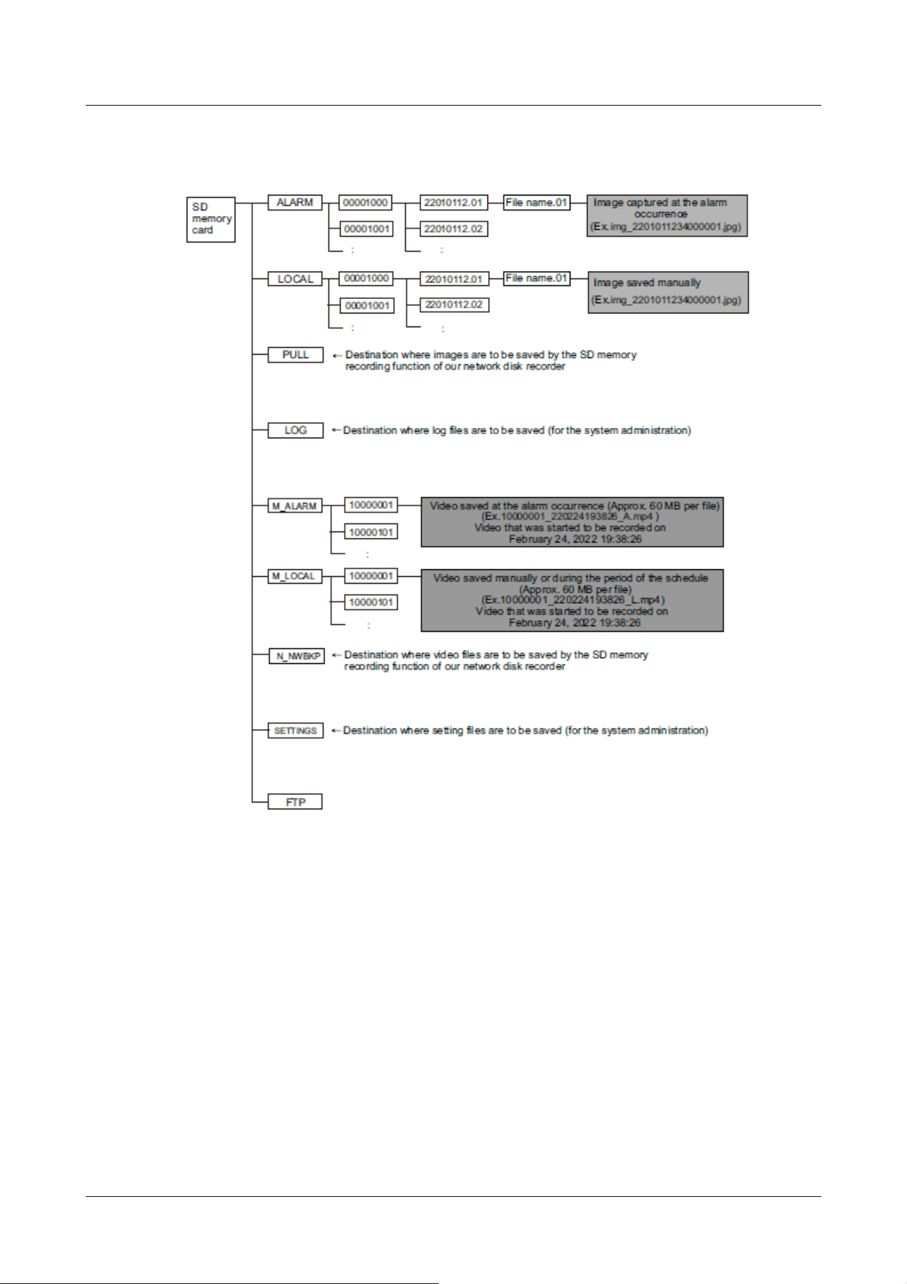
20.3.1 Directories of PTZ Camera, Fixed cameras
20 Other
20.3 Directory structure of SD Memory Card
587
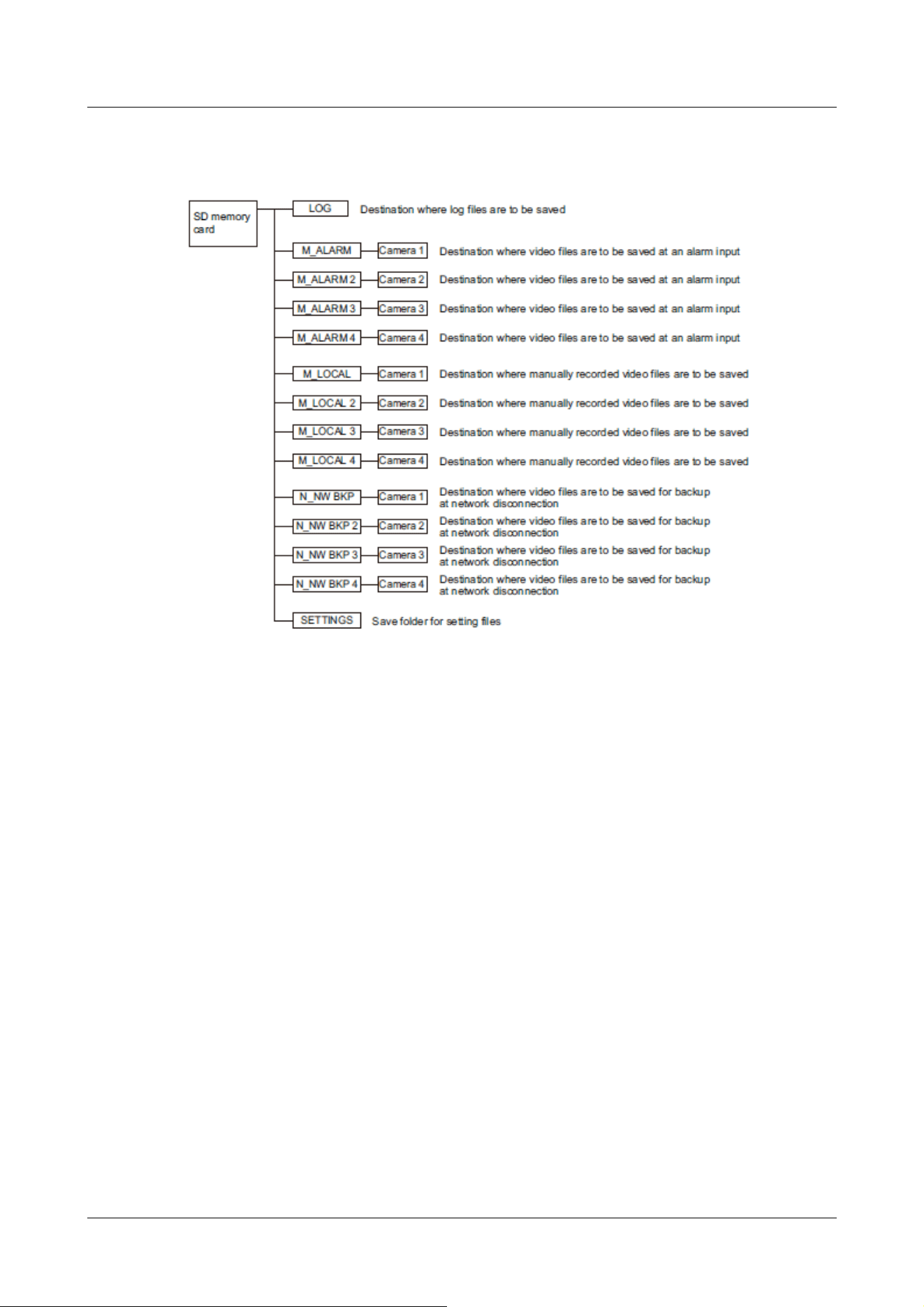
20.3.2 Directory Configuration of Multi-directional Camera
20 Other
20.3 Directory structure of SD Memory Card
588

21 Change history
Ver 1.000.000 (2023.02.15)
Add new product
Multi-directional + PTZ Camera
WV-X86531-Z2, WV-X86530-Z2
Ver 1.001.000 (2023.03.08)
Add new product
Multi-directional dual sensor camera
WV-S85702-F3L, WV-S85402-V2L, WV-U85402-V2L
Ver 1.002.000 (2023.09.12)
Add new product
Mini Box Sphere IR-PTZ
WV-S66700-Z3L, WV-X66700-Z3LS, WV-S66700-Z3, WV-X66700-Z3S
WV-S66600-Z3L, WV-X66600-Z3LS, WV-S66600-Z3, WV-X66600-Z3S
WV-S66300-Z4L, WV-X66300-Z4LS, WV-S66300-Z3L, WV-X66300-Z3LS
WV-S66300-Z4, WV-X66300-Z4S, WV-S66300-Z3, WV-X66300-Z3S
New compact dome
WV-X35402-F2L, WV-X35302-F2L
WV-S35402-F2L, WV-S32402-F2L, WV-S35302-F2L, WV-S32302-F2L
New functions and addendum (Firmware Ver.2.33)
・
The following was added to the communication protocol FTP/SFTP function of the file transfer
function. (→16.2.2 Configuring FTP/SFTP transmission function)
・Add 2fps, 3fps to Image-Update Rate
・Add 1920x1080 to Image capture size for pre-alarm
・Expand image destination server to two locations
21 Change history
589

・
A 0.5s, 1s, 2s, 3s, 4s was added to the alarm absence detection period. (→14.1 [Alarm] to
set alarm operation)
・
The function to change the image quality at the time of sunrise and sunset has been added to
the schedule setting. (→17 [Schedule] for scheduling)
・
Added the [Enable/Disable] setting for [SNMP] in the [Advanced] tab of the Network page. (→
16.2.7 Set SNMP)
・
You can now edit the camera title by adding and clicking the title edit icon next to the camera
title. (→2.3 Viewing images from a PC)
・
You can now select [SD Memory Card File System Format] and [FAT(FAT16/FAT32/exFAT)]
and [ext(ext4] to select the file system format of the SD memory card. (→9.2 [SD memory
card] for setting SD Memory Cards)
Ver 1.003.000 (2023.09.29)
New functions and addendum (Firmware Ver.2.40)
・
Add 1280x720 image capture size for Stream (1) and Stream (2) of the Multi-directional
sensor camera 4MP model.(→10.3 [Image] for setting up streams)
・
The information in the notes has been changed due to the relaxation of frame rate restrictions
during [GOP control].(→10.3 [Image] for setting up streams)
・
The note description has been changed because the tracking performance of the auto track
function may lower depending on the [Maximum shutter] setting.(→11.3 Set auto-tracking
(Auto-tracking screen))
・
A note description has been added regarding function settings that are not applied when
settings data is restored.(→18.5 [Data] to back up/restore configuration logs)
Ver 1.004.000 (2023.12.15)
Add new product
New compact dome
WV-U35401-F2L, WV-U35301-F2L
WV-U31401-F2L, WV-U31301-F2L
21 Change history
590

Ver 1.005.000 (2023.12.26)
Add new product
New X Fixed cameras
WV-X15300-V3L, WV-X15300-V3LN, WV-X22300-V3L, WV-X25300-V3LN
WV-X15600-V2L, WV-X15600-V2LN, WV-X22600-V2L, WV-X25600-V2LN
WV-X15700-V2L, WV-X15700-V2LN, WV-X22700-V2L, WV-X25700-V2LN
Ver 1.006.000 (2024.02.27)
New functions and addendum (Firmware Ver.2.50/[New X Fixed] Ver.3.10)
・
A SAN entry field has been added to the CSR creation screen.(→16.3 Setting up HTTPS)
・
The initial password for data encryption has been changed to blank.(→15.5 [Data
encryption] for setting up data encryption)
・
The names of connection options for HTTP and HTTPS have been changed. [TLS1.2] has been
changed so that it can now be enabled or disabled.(→16.2.5 Set up HTTPS)
・
A "Diag." function has been added to HTTP alarm notifications.(→14.12.2 Set the HTTP
alarm notification)
・
The [Security] settings screen has been added to the [User mng.] menu. Settings related to
security can be configured in this section.(→15.6 [Security] to configure security)
・
"MD5" has been removed from the SNMPv3 [Authentication].(→16.2.7 Set SNMP)
・
"EAP-MD5" has been removed from the [EAP method] for IEEE 802.1X.(→15.4 [IEEE
802.1X] to configure IEEE 802.1X)
Ver 1.007.000 (2024.03.18)
Add new product
New X Fixed cameras
WV-X15500-V3L, WV-X15500-V3LN, WV-X22500-V3L, WV-X25500-V3LN
Ver 1.008.000 (2024.05.27)
New functions and addendum (Firmware Ver.2.60/[New X Fixed] Ver.3.20)
・
In order to change the font of the live image screen and i-PRO logo design, a description has
been added to the announcement.(→2.3.2 About live image pages)
21 Change history
591

Ver 1.009.000 (2024.05.28)
Add new product
Mini Box Sphere IR-PTZ(ClearSight coating model)
WV-S66700-Z3LN, WV-X66700-Z3LK, WV-S66700-Z3N, WV-X66700-Z3K
WV-S66600-Z3LN, WV-X66600-Z3LK, WV-S66600-Z3N, WV-X66600-Z3K
WV-S66300-Z4LN, WV-X66300-Z4LK, WV-S66300-Z3LN, WV-X66300-Z3LK
WV-S66300-Z4N, WV-X66300-Z4K, WV-S66300-Z3N, WV-X66300-Z3K
Ver 1.010.000 (2024.08.06)
Add new product
Corner cameras
WV-X25580-F2LN2
Ver 1.011.000 (2024.10.23)
Add new product
Indoor PTZ cameras
WV-S61702-Z3, WV-S61602-Z3
Ver 1.012.000 (2024.10.25)
New functions and addendum (Firmware Ver.2.70/[New X Fixed] Ver.3.30)
・
Due to the change of icons, the images on the live image screen have been replaced.
(→2.1 Initial Setting)
(→2.2 Initial setting (Multi-directional/PTZ integrated camera))
(→2.3.2.1 Live image pages of Fixed Cameras)
(→2.3.2.2 Live image pages of the PTZ camera)
(→2.3.2.3 Live image pages of Multi-directional Cameras)
(→2.3.2.4 Live image pages of Multi-directional/PTZ integrated cameras)
(→2.3.3 Monitor images from multiple cameras)
(→2.7 Display the log list)
(→2.8.1 When playing JPEG images stored on the SD Memory Card)
(→2.8.2 Play back the image of the stream stored on the SD Memory Card)
(→15.5 [Data encryption] for setting up data encryption)
21 Change history
592

・
The setting window for connecting Remote Monitoring was added to "Remote Monitoring" of
"Network".(→16.5 Use Remote Monitoring)
Ver 1.013.000 (2025.01.21)
Add new product
Aero PTZ cameras
WV-X67700-Z3-3, WV-X67700-Z3L3, WV-X67701-Z3L3, WV-X67710-Z3-1,
WV-X67710-Z3-3, WV-X67710-Z3L1, WV-X67710-Z3L3, WV-X67711-Z3L3,
WV-X67300-Z4-3, WV-X67300-Z4L3, WV-X67301-Z4L3, WV-X67310-Z4-1,
WV-X67310-Z4-3, WV-X67310-Z4L1, WV-X67310-Z4L3, WV-X67311-Z4L3
Ver 1.014.000 (2025.01.31)
New functions and addendum (Firmware Ver.2.80/[New X Fixed] Ver.3.40)
・
Notes on multicast have been added to [Note:] in [Camera Control Panel]-[Audio output
volume (PC to Camera)] and [Camera Control Panel]-[Mic input volume (Camera to PC)].
(→2.3.2.1 Live image pages of Fixed Cameras)
(→2.3.2.2 Live image pages of the PTZ camera)
(→2.3.2.3 Live image pages of Multi-directional Cameras)
(→2.3.2.4 Live image pages of Multi-directional/PTZ integrated cameras)
・
Due to the change of icons on the live screen of Aero PTZ cameras, the images on the live
screen of PTZ cameras listed have been replaced. A single picture of all models of PTZ cameras
is available.
(→2.3.2.2 Live image pages of the PTZ camera)
・
[Detailed setting] key was added to the settings menu on the tablet device screen.
(→2.4.2.1 Viewing images of Fixed cameras from a tablet terminal)
(→2.4.2.2 View PTZ camera images from a tablet terminal)
(→2.4.2.3 Viewing Multi-directional Camera Images from a Tablet Terminal)
(→2.4.2.4 Viewing images of the Multi-directional/PTZ camera from the tablet terminal)
・
About the Camera-specific data table
The size of the [RAM capacity] of the new X fixed camera([Model name]) has been changed
from "450MB" to "1024MB".(→6.1 [Software mng.] for installing, uninstalling, and
upgrading function extension software)
・
Added [Host name] to "IPv4 network".(→16.1 Networking [Network])
21 Change history
593

・
The Server Certificate in PKCS#12 format is now supported.
Accordingly, a field for entering [Password (0 to 30 characters)] was added to change from [CA
Certificate install] to [Server certificate or server certificate with private key].(→16.2.5 Set
up HTTPS)
・
[CA Certificate] has been changed to [Server Certificate] in HTTPS settings window.(→16.2.5
Set up HTTPS)
Revised description
・
Added a note about the "Camera continues to move in the tilt direction even after you have
finished operating it with the control pad on [PTZ] tab of Live image pages."(→20.2 Trouble!?)
Ver 1.015.000 (2025.02.14)
Add new product
AI Outdoor IR Bullet Camera
WV-X15701-Z3L, WV-X15701-Z3LN, WV-X15501-Z3L, WV-X15501-Z3LN
WV-X15501-Z1L, WV-X15501-Z1LN, WV-X15502-Z1L, WV-X15502-Z1LN
WV-X15301-Z1L, WV-X15301-Z1LN, WV-X15302-Z1L, WV-X15302-Z1LN
WV-S15701-Z3L, WV-S15701-Z3LN, WV-S15501-Z3L, WV-S15501-Z3LN
WV-S15501-Z1L, WV-S15501-Z1LN, WV-S15301-Z1L, WV-S15301-Z1LN
Ver 1.016.000 (2025.05.30)
Add new product
U-series camera with edge AI
WV-U25551-V3L, WV-U15550-V3L, WV-U21550-V3L, WV-U11550-V3
WV-U25351-V3L, WV-U15350-V3L, WV-U21350-V3L, WV-U11350-V3
WV-U15750-V3L, WV-U25751-V3L, WV-U22750-F3L, WV-U25550-F3L
WV-U22550-F3L, WV-U25350-F3L, WV-U22350-F3L
New functions and addendum (Firmware Ver.2.85/[New X Fixed][AI Outdoor IR
BulletX] Ver.3.45)
・
The earpiece button and transmission button were added at the top of the live image screen.
In conjunction with the above, the images on the live screen of cameras listed have been
replaced. A single picture of all models of cameras is available.
(→2.3.2.1 Live image pages of Fixed Cameras)
21 Change history
594

(→2.3.2.2 Live image pages of the PTZ camera)
(→2.3.2.3 Live image pages of Multi-directional Cameras)
(→2.3.2.4 Live image pages of Multi-directional/PTZ integrated cameras)
・
Detailed settings have been added for alarm types that link to HTTP alarm notification settings.
(→14.12.2 Set the HTTP alarm notification)
Revised description
・
Added a note about the "Cannot unmute earpiece volume in live video when accessed in
HTTPS."(→20.2 Trouble!?)
Ver 1.017.000 (2025.07.03)
Revision described
・
The description of white LED Light was added for the explanation on [Auto2(IR Light)] in [Day
& Night(IR)].(→10.4.1 To adjust the image quality (image quality adjustment screen))
・
Revision of important descriptions regarding the disturbance detection function.(→14.7
[SCD area] to set up undesired detection)
21 Change history
595