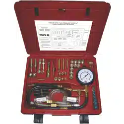
Master Fuel Pressure
Tester Kit
User’s Manual
FIT550

SAFETY GUIDELINES TO FOLLOW WHEN WORKING ON VEHICLES
DO NOT
DO NOT smoke when working on fuel systems.
DO NOT use the Fuel Pressure Tester Kit on diesel or ex fuel engines.
DO NOT connect or disconnect fuel system ttings with the ignition on.
DO NOT lay tools on the vehicle battery. A short may occur, causing damage or personal injury.
DO NOT leave the vehicle unattended with the engine running or while performing tests.
DO NOT allow unauthorized personnel in the test area.
DO NOT allow test hoses or test instrument harnesses to lie near engine cooling fan, exhaust manifolds, etc.
DO NOT work on fuel systems where a ame or spark could be present. This includes furnaces, space heaters,
exposed spark plug wires, etc.
DO NOT allow fuel to spill on hot engine parts. If a leak or spill develops, turn off ignition, disable fuel pump, and
clean up spill immediately. exposed spark plug wires, etc.
1

SAFETY GUIDELINES TO FOLLOW WHEN WORKING ON VEHICLES
DO
Wear approved eye protection.
Refer to the manufacturer’s vehicle service or repair manuals for specic information regarding pressure testing
values, procedures, and test port locations.
Follow all manufacturers’ cautions, warnings, and instructions.
Keep clothing, tools and yourself away from hot or moving engine parts.
Clean fuel system connections before loosening. Dirt in the system could result in damage.
Wrap a cloth around ttings when loosening to prevent spray or spilling of fuel.
Provide proper ventilation of gasoline and exhaust fumes.
Use hose clamps on all hose adapters.
Make sure quick-disconnect couplers snap together fully and there is no fuel leakage.
Make sure the battery is fully charged, and the vehicle has an adequate supply of fuel.
Use two wrenches to loosen or tighten fuel system connections to prevent damage or twisting of fuel lines.
Check the general condition of the engine and fuel system. Check the fuel lines, ignition wires, battery cables,
electrical wiring, and fuses. Check the fuel tank ller cap and the venting system.
Carefully relieve residual fuel pressure per manufacturer’s recommended procedure.
Have a dry chemical re extinguisher on hand, and know how to use it.
2

FUEL INJECTION SYSTEMS - GENERAL INFORMATION
Automotive fuel systems and access points are so varied that it is not possible to list all of the test adapter applications.
Always consult a reliable shop manual, or consult the car manufacturer for the recommended test procedure and connections.
There are two basic types of automotive fuel injection systems:
1. Port Fuel Injection (PFI) - Separate fuel injectors supply fuel to each cylinder.
2.Throttle Body Injection (TBI) – Fuel is injected from a point on the intake manifold above the throttle plate.
Both systems have a supply side, which provides fuel for the injectors, and a return side, which sends excess fuel back to the
fuel tank.
There are three basic ways to check fuel system pressure:
1. Many domestic cars with PFI systems are equipped with a test port. Connect the proper test adapter to the Test Gauge,
couple the adapter to the test port, and perform the test.
2. On some systems, an end-of-hose connection is necessary. Some PFI systems have a exible hose connection. For
this type of system, connect a single barb tting with a hose clamp to perform the test. Other systems have a fuel bolt or
banjo type tting as an access point.
3. The third method of fuel pressure testing is in-line connecting. This method requires separating the fuel line and installing
the Test Gauge and adapters in series.
Most manufacturers require that you relieve the fuel pressure before connecting to or disconnecting from the fuel system.
To relieve the fuel pressure, it may be necessary to disconnect or disable the fuel pump. Some models may have two fuel
pumps, and both must be disabled. After the fuel pump(s) are disabled, run the engine until it stalls, then try to restart it for
three to ve seconds. When the fuel system has been drained of fuel it is ready for testing. Connect the proper test adapters
and the Test Gauge, reconnect the fuel pump and perform the tests. When the tests are nished, repeat the procedure to
relieve the fuel pressure before removing the Test Gauge.
3

CHECKS TO MAKE BEFORE TESTING FUEL SYSTEM
The following items should be checked. Any faults that are found must be corrected before a proper fuel system test
can be performed.
Check for loose or disconnected vacuum lines. Look for coolant or excessive oil leaks. Listen for any audible air leaks,
unusual noises, engine rattles or knocks. Check valve timing and adjustment.
Electrical System
1. If engine won’t start, check for ignition spark. If no spark
is present, service ignition system. The ignition res the
fuel injector on most systems so that if a spark plug is
not ring, that cylinder’s injector will not be ring.
2. Observe Check Engine lamps or other computer fault
indicators.
3. Look for broken, disconnected, or arcing ignition wires.
4. Look for disconnected distributor, or arcing cap or rotor.
5. Check for loose or corroded component grounds.
6. Look for disconnected electrical components.
7. Check battery condition. A weak battery will affect
proper fuel pump delivery or injector triggering. Battery
voltage should be more than 12 volts.
8. Check basic operation of the charging system.
9. Look for loose or corroded battery cables.
Fuel System
1. Make sure fuel tank has sufcient fuel (do not rely on
the fuel gauge).
2. Look for broken, loose, or corroded metal, rubber or
plastic fuel lines.
3. Check for water or other contaminates in fuel.
4. Check condition of fuel system related fuses or
solenoids.
5. Check condition of fuel tank venting systems.
6. Check condition of fuel tank ller cap.
7. On vehicles equipped with inertia switch, check and
make sure switch has not been tripped.
4

1. Do not smoke.
2. Wear approved safety glasses.
3. Have a Class B dry chemical re extinguisher nearby.
4. With ignition off, release fuel tank ller cap.
5. Disable the fuel pump. Follow the manufacturer’s recommended procedure.
a. Some vehicles may have two fuel pumps. Both pumps must be disabled.
b. A common method of disabling the fuel pump is to remove the fuel pump fuse.
c. On some vehicles, removing the fuse also disables the fuel injectors or ignition system, so another method of
disabling the pump must be used.
d. On some vehicles, the fuel pump can be disabled by disconnecting the fuel pump wiring harness.
e. On Ford vehicles equipped with an inertia switch, check that the switch has not been tripped. The inertia switch is
usually located in the trunk.
6. Turn on the ignition and start the engine. If engine will not start, check ignition system for spark. If no spark is present,
refer to the vehicle service manual for No Start Diagnostics.
7. Run the engine until it stalls.
8. Try to restart the engine for 3 to 5 seconds. For some Ford/Mercury/Lincoln vehicles with inertia-switch, engage the
starter for 15 seconds to relieve fuel pressure.
9. Turn ignition off.
TYPICAL PROCEDURE TO RELIEVE FUEL SYSTEM PRESSURE
5

6
This Page Left Blank Intentionally.

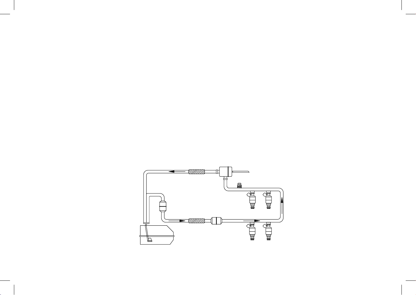
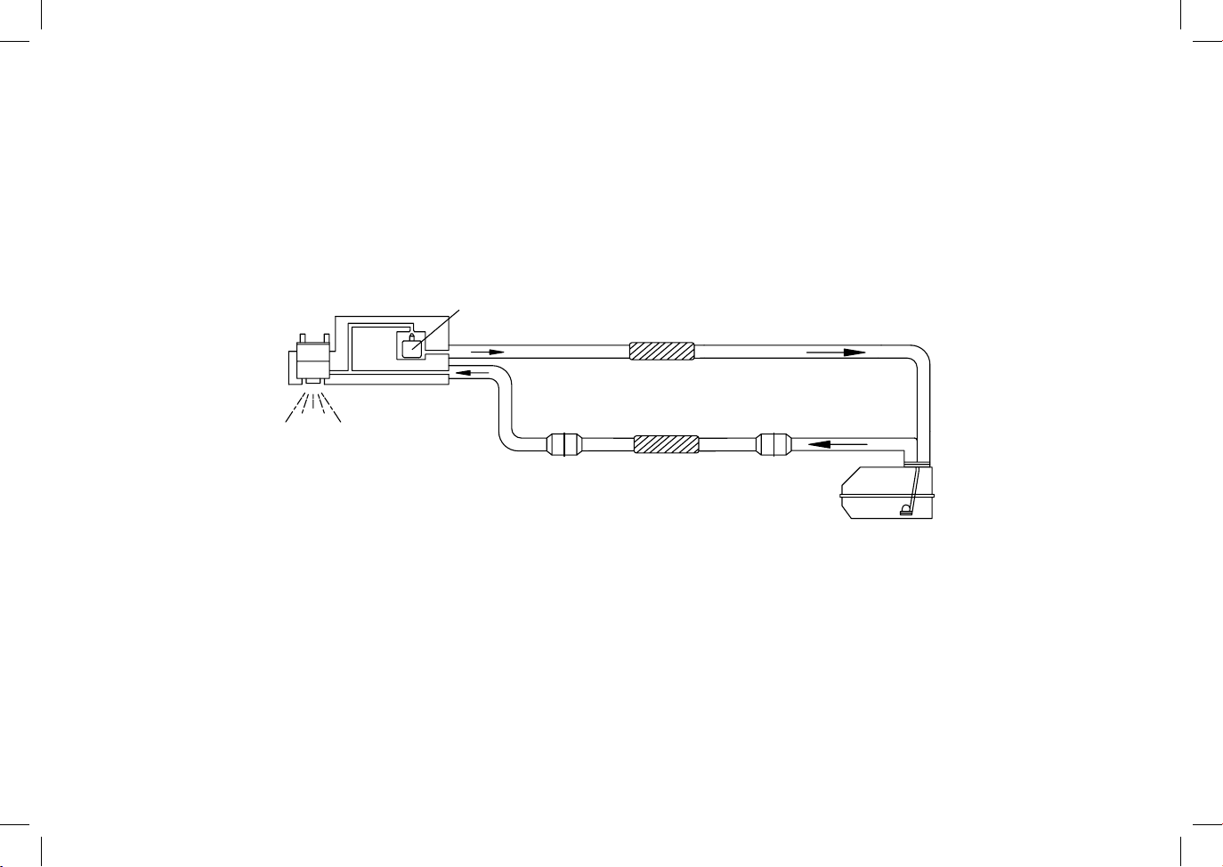
1. Refer to Figure 1, Typical Multi-Port Fuel Injection
System With Test Port. With engine off, locate fuel
pressure test port (Schrader valve) and attach the
Test Gauge. If no Test Port is provided, residual
pressure must be released before fuel system ttings
are loosened. Connect the Test Gauge to the access
point using the correct adapter. Always wrap a shop
towel around the tting before loosening.
2. If the adapter you need is a banjo bolt adapter, ours
are designed for use with standard depth banjos.
If a car manufacturer uses a non-standard banjo,
more than one washer maybe needed on either or
both sides of the banjo. Our M12 x 1.25 banjo bolt
adapter may need one or more thick or thin washers
depending on the application.
3. Connect the Test Gauge into the system. Reactivate
the fuel pump and start the engine.
4. Fuel pressure should rise to slightly above operating
pressure and then stabilize at operating pressure, per
the manufacturer’s’ specications.
5. Check for leaks and repair as required.
6. If engine will not start, check ignition system for spark.
If no ignition spark is present, refer to vehicle service
manual for No Start Diagnostics.
TESTING TYPICAL PORT FUEL INJECTION SYSTEM
7
7. If the system has an adjustable fuel pressure
regulator, it should maintain system pressure while
the engine is running. If a compensating fuel
pressure regulator is used, fuel pressure may vary,
depending on manifold vacuum.
8. Locate a exible hose on the fuel return side and
gently squeeze off return ow briey. Never squeeze
a steel braided or plastic hose. Pressure should
increase rapidly.
CAUTION: Some fuel pumps can be damaged by this
test. This test should not be performed unless
recommended by the manufacturer.
CAUTION: Pressure could exceed 75 psi and may blow
apart any loose ttings or defective lines or
hoses. Observe the condition of fuel system
components before performing this test.
9. If the pressure readings are acceptable, some
manufacturers also require a ow test. If so, open
the fuel system into a graduated plastic container and
measure the ow rate. Consult a service manual for
the acceptable ow rate. Close the fuel system.
10. Turn ignition off and observe the residual pressure.
Some manufacturers specify a minimum holding time.
In some cases, to get the right combination of threads, multiple test adapters may have to be used.
For test pressures specications, consult the vehicle service manual.
and press the bleed valve on the hose to relieve the
system pressure.
13. Remove the Test Gauge and reconnect all the fuel
lines.
14. Start the engine and check for leaks.
15. Remove residual fuel from all Test Gauge hoses.
If fuel remains in the Test Gauge hose, install any
adapter in the test hose quick connect. Put the
Test Gauge hose and bleed-off tube in a disposal
container. Press the bleed valve on the Test Gauge.
The fuel will drain into the container.
FIGURE 1
TYPICAL MULTI-PORT FUEL INJECTION SYSTEM WITH TEST PORT
8
FUEL PRESSURE TEST POINT
MANIFOLD VACUUM
FLEX HOSE
FLEX HOSE
FUEL PRESSURE LINE
IN-TANK FUEL
PUMP
FUEL RETURN LINE
PUMP INLET FILTER
PRESSURE REGULATOR
FILTER
FILTER
FUEL INJECTORS
11. If you have an injector pulse tester you can test
injectors one by one as follows: 1)Turn the ignition on.
2) Observe the fuel pressure. 3) Pulse one injector.
4) Turn ignition off. Move injector pulse tester to next
injector and repeat test sequence. Continue test
procedure on remaining injectors.
CAUTION: Do not repeat this test more than the
manufacturer recommends. The engine
may become ooded, or the oil can become
contaminated.
12. Deactivate the fuel pump. With the ignition off, put
the Test Gauge bleed-off tube in a disposal container

1. Deactivate the fuel pump(s) and relieve fuel
system pressure.
2. Remove the air cleaner assembly.
3. On GM vehicles, temporarily plug the Thermac
vacuum port on the throttle body.
4. Refer to Figure 2, Typical TBI Fuel Injection
System. Using the adapters supplied, install
the Test Gauge in-line somewhere between the
fuel lter and the throttle body. If longer pieces
of 3/8” hose are needed, cut from 3/8” fuel line
hose. Use hose clamps on the hose.
5. If steel tubing is disconnected, use two wrenches
to prevent damage.
6. On some vehicles it may be easier to put the car
on a lift and test from underneath.
7. Reactivate the fuel pump, start the engine, and
check for leaks.
8. When fuel pressure has stabilized, observe Test
Gauge. Consult a service manual for the exact
pressure reading required.
9. Turn ignition off. Deactivate the fuel pump. Put
test gauge bleed-off tube in a disposal container
and press bleed valve button to relieve fuel system
pressure.
10. Remove Test Gauge and reconnect all fuel lines.
11. Start engine and check for leaks.
12. Remove residual fuel from all Test Gauge hoses.
If fuel remains in the Test Gauge hose, install any
adapter in the test hose quick connect. Put the
Test Gauge hose and bleed-off tube in a disposal
container. Press the bleed valve on the Test Gauge.
The fuel will drain into the container.
13. On GM vehicles, remove the plug from the Thermac
vacuum port.
14. Replace air cleaner.
TESTING TYPICAL TBI SYSTEMS
9
In some cases, to get the right combination of threads, multiple test adapters may have to be used.
For TBI test pressures specications, consult the vehicle service manual.
10
FIGURE 2
TYPICAL TBI FUEL INJECTION SYSTEM
INJECTOR
FLEX HOSE
FLEX HOSE
RETURN LINE
PRESSURE LINE
FILTER
FILTER
PUMP INLET FILTER
POSITION AND NUMBER OF FILTERS MAY VARY.
PRESSURE REGULATOR

11
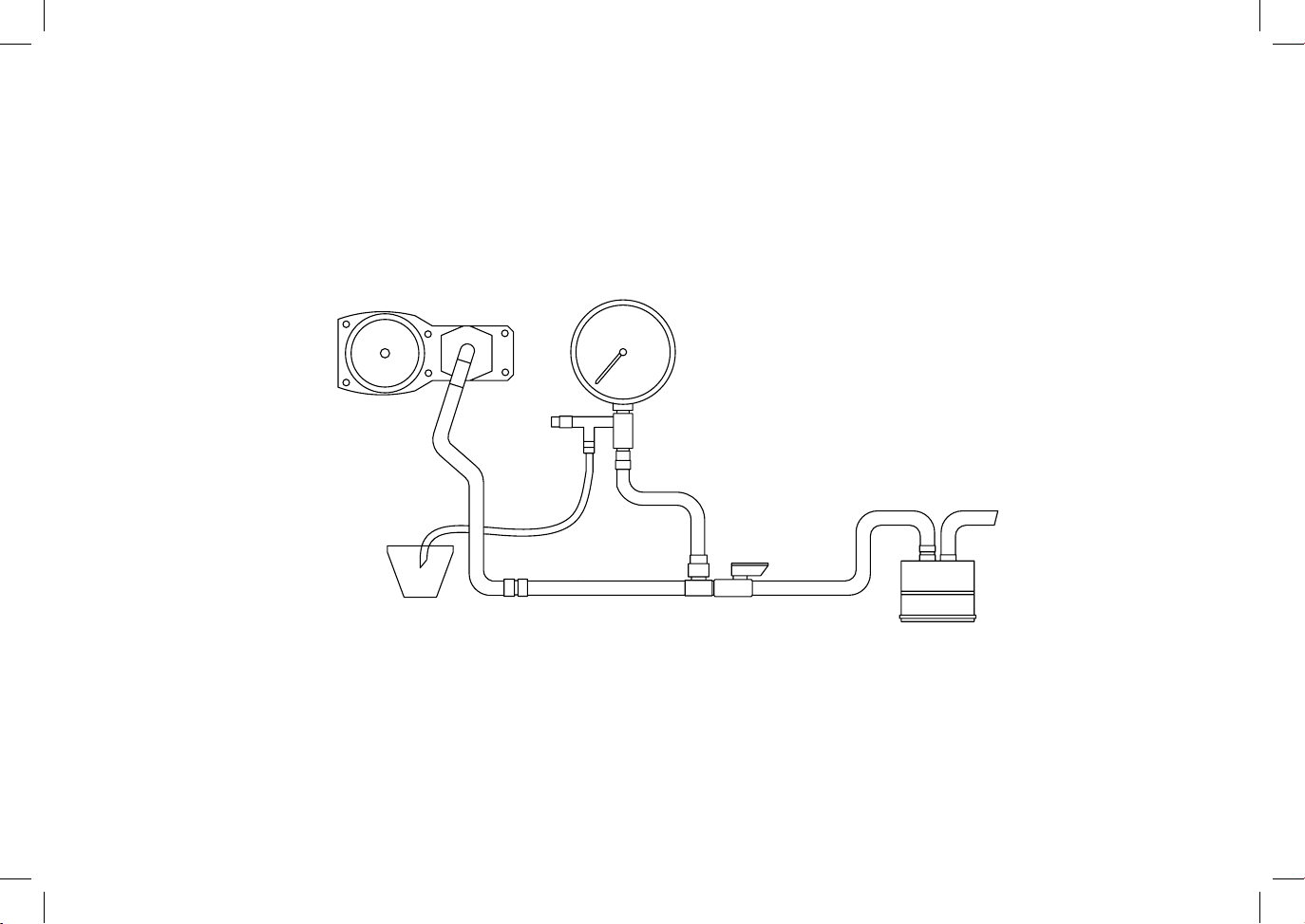
Preparation:
1. Relieve fuel system pressure.
2. Clean any dirt off the top of the fuel distributor.
3. Refer to Figure 3, Typical C.I.S. Fuel Injection
System Test Gauge Connections. Hook up the
Test Gauge between the fuel distributor and the
control pressure regulator. The Test Hose without
the ow control valve should be connected to the
fuel distributor. The hose with the valve should be
connected to the hose that was removed from the
fuel distributor, or connected directly to the control
pressure regulator.
The following C.I.S. tests can be made with this Test Kit:
Cold Control Pressure – engine cold, test valve open
Warm Control Pressure – engine warm, test valve open
System Pressure – engine cold or warm, test valve closed
Rest Pressure – engine warm, test valve open
Fuel Delivery Rate
CAUTION: Adapters with o-rings should be handtightened only.
In some cases, to get the right combination of threads, multiple test adapters may have to be used.
For C.I.S. test pressures specications, consult the vehicle service manual.
TESTING TYPICAL BOSCH C.I.S. SYSTEMS
To Test Cold Control Pressure:
1. The engine should be cold after standing several
hours or overnight.
2. Disconnect electrical connector at warm-up regulator
and auxiliary air valve.
3. Connect Test Gauge and open valve on Test Hose.
4. Remove the air from the system. Put the Test Gauge
bleed-off tube in a disposal container. Activate the fuel
pump, but do not start the engine. With the fuel pump
operating, bleed until air is removed from system.
5. Start the engine and note pressure reading
immediately after starting. Compare to manufacturer’s
specications.
6. If the Cold Control Pressure is not correct, the warm-up
regulator may be at fault.
12
FIGURE 3
TYPICAL C.I.S. FUEL INJECTION SYSTEM TEST GAUGE CONNECTIONS
Tests Continued on Next Page
FUEL DISTRIBUTOR
TEST GAUGE
TEST HOSE
BLEED OFF
BLEED OFF
TUBE
VALVE
FLOW CONTROL
VALVE
CONTROL
PRESSURE
REGULATOR
TO TANK
DISPOSAL CONTAINER

13
To Test Warm Control Pressure:
1. Reconnect wiring to warm-up regulator and auxiliary air
valve.
2. Open valve on Test Hose.
3. Start engine and run for specied time.
4. Compare Warm Control pressure readings with
manufacturer’s specications.
To Test System Pressure:
1. Test can be performed with engine cold or warm.
2. Reconnect wiring to warm-up regulator and auxiliary air
valve.
3. Close valve on Test Hose (closed valve eliminates
control pressure.)
4. Start engine and run for specied time.
5. Compare System Pressure reading with manufacturer’s
specications.
To Test Rest Pressure:
1. Open valve on Test Hose.
2. With engine at normal operating temperature, energize
fuel pump or start engine.
3. Turn engine off or disable pump when pressure reading
stabilizes.
4. Compare pressure readings taken at specied time
intervals with manufacturer’s specications.
5. If the Rest Pressure drops too quickly, check for leaks
at o-ring and fuel line connections.
6. If no external leaks are found, consult the service
manual for causes of low fuel pressure.
To Test Fuel Delivery Rate:
1. If pressure testing nds no problems in the fuel injection
system, the fuel pump should be checked.
2. Consult manufacturer’s specications for the correct
fuel volume and time period to test.
3. Hook up the Test Gauge for a pressure test and put the
bleed-off tube into a graduated container.
4. Start the engine or activate the fuel pump.
5. Collect fuel in the container for the specied period of
time. Compare the volume of fuel collected with the
manufacturer’s specications.
6. Turn off the engine or disconnect the fuel pump.
To Complete Testing:
1. Deactivate fuel pump. With ignition off, put Test
Gauge bleed-off tube in a disposal container and press
bleed valve on the Test Gauge to relieve fuel system
pressure. The fuel will drain into the container.
2. Remove Test Gauge. Reconnect all fuel lines and
any vacuum lines or wiring connectors that were
disconnected.
3. Start engine and check for fuel system leaks.
ENGLISH / METRIC
PRESSURE EQUIVALENTS
PRESSURE
CONVERSION FACTORS
14
0.5 0.034 3.45 0.0352
1 0.069 6.89 0.0703
1.25 0.086 8.62 0.0879
1.5 0.103 10.34 0.1054
1.75 0.12 12.07 0.123
2 0.138 13.79 0.1406
5 0.345 34.47 0.3515
10 0.689 68.95 0.703
15 1.034 103.42 1.0545
20 1.379 137.89 1.406
25 1.724 172.36 1.75
30 2.068 206.84 2.109
35 2.413 241.31 2.4605
40 2.758 275.79 2.812
50 3.447 344.74 3.515
60 4.137 413.68 4.218
70 4.826 482.63 4.921
75 5.167 517.1 5.2725
80 5.516 551.58 5.624
90 6.205 620.52 6.327
100 6.895 689.47 7.03
psi bar kPa kg/cm2
psi kPa 6.8946
psi bar 0.0689
psi
kg/cm
2
0.0703
psi
in. H
2
O
27.68
psi in. mercury 2.0360
psi cm. mercury 5.1715
kPa psi 0.145
kPa bar 0.01
kPa
kg/cm
2
0.0102
bar psi 14.504
bar kPa 100
bar
kg/cm
2
1.02
kg/cm
2
psi 14.22
kg/cm
2
kPa 98.074
kg/cm
2
bar 0.9807
To Convert To Multiply By
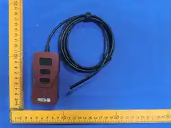
BASIC TESTER
3 1/2”, 0-100 PSI Test Gauge and Hose assembly with
bleed-off valve. Provides a convenient method of purging
air and relieving pressure after testing. Can also be used for
observing volume of fuel.
JC0032-0129
CIS / TBI Test Hose – use when testing CIS or TBI systems
where the in line connections are needed. Includes shut-off
valve for both control & primary system pressure checks.
The gauge hose should be used with CIS testing, to purge
all air from the test gauge when running tests.
15
JC0032-0146
Interchange Hose
JC0032-0145
Interchange Hose
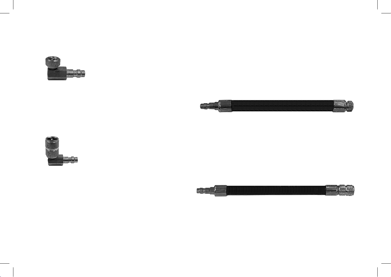
SCHRADER VALVE TEST PORT ADAPTERS
JC0180-1462 -----Small Schrader Valve 90 Degree Adapter
Small Schrader Type Test Hose with .308” X 32 Thread
Common applications – Ford EFI.
JC0180-1463 ---------- Standard Schrader Valve 90 Degree Adapter
JC0032-0128
Large Schrader Type Test Hose with 7/16” X 20 Thread.
Common applications include Chrysler, Jeep, and GM with test
ports.
JC0032-0127
16
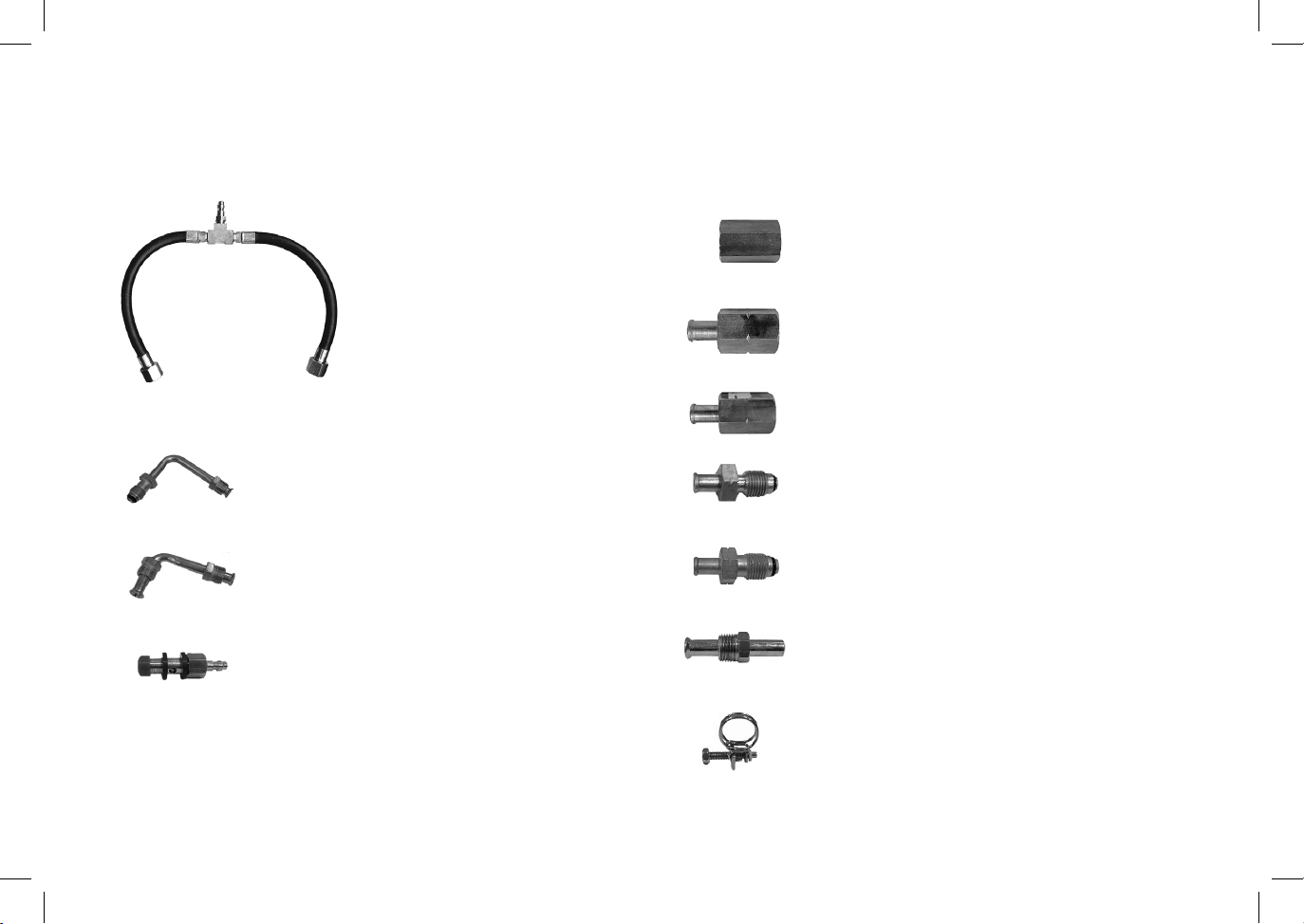
IN-LINE TBI ADAPTERS
JC0180-1453------- Bent Tube with 5/8”
Flare Nut to M16 with
O-ring
JC0180-1441 ----- Bent Tube with 5/8”
Flare Nuts
JC0180-1459 ------ M12 X 1.25 Banjo Bolt
JC0180-1444 ------ 5/8”-18 to M16 Union
JC0180-1443 ------- Female M14 to 3/8” Tube
JC0180-1442 ------ Female M16 to 3/8” Tube
JC0180-1455 ------ M14 with O-Ring to 3/8”
Tube
JC0180-1454 ----- M16 with O-Ring to 3/8”
Tube
JC1000-5061 ----- Straight Flared
Tube with 5/8” Flare Nut
JC1000-5062 ----- Hose Clamp Kit
17
JC0032-0130 ----- Connecting
Hose
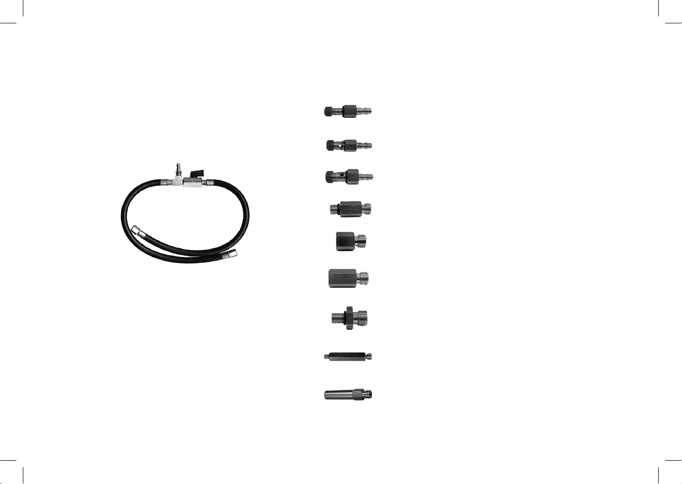
IN-LINE - C.I.S., C.I.S.-E, & K-JETRONIC ADAPTERS
JC0032-0129
Connecting Hose &
Valve Assembly
JC0180-1458 -------- M10 Banjo Bolt with Washer
JC0180-1460 -------- M12 X 1.5 Banjo Bolt
JC0180-1451 -------- M10 Male to M12 Male
JC0180-1445 -------- M8 Female to M12 Male
JC0180-1446 -------- M10 Female to M12 Male
JC0180-1450 -------- M8 Male to M12 Male
JC0180-1452 ------- Long M8 Male to M12 Male
JC0180-1461 ------- Long M8 Female to M12 Male
JC0180-1457 -------- M8 Banjo Bolt with Washer
18
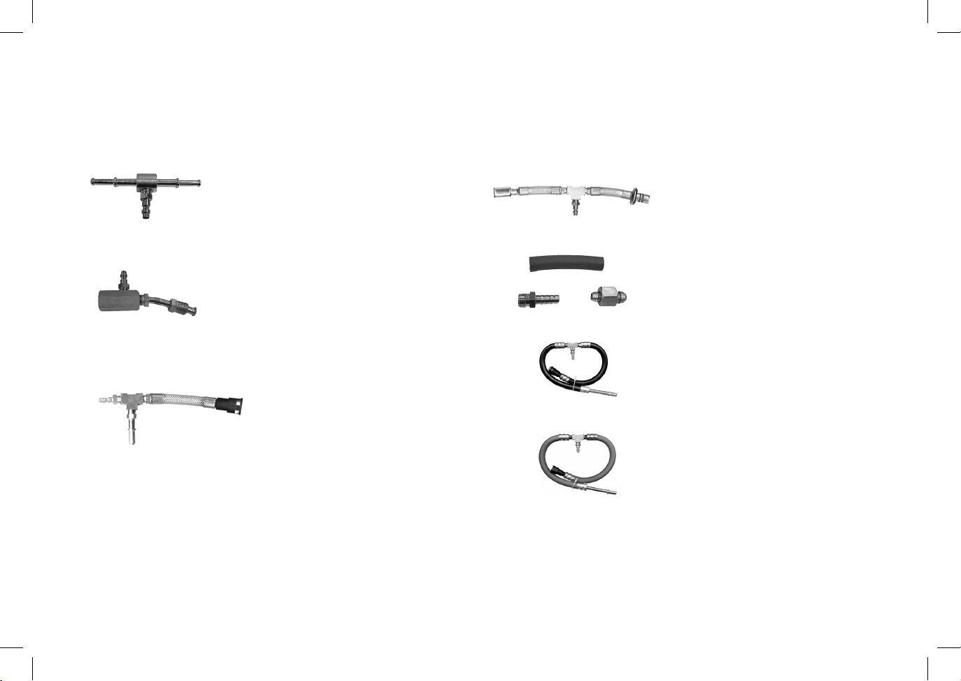
IN-LINE SPECIAL ADAPTERS
JC0180-1449 ----- Manifold with Quick
Connect
JC0180-1448 ----- GEO / Isuzu
Adapter
JC1000-5060 - Ford CFI Hair Pin
Hose Adapter
JC1000-5059 - Ford EFI Spring
Lock Hose
Adapter
JC1000-5058 - Volvo Adapter Set
JC1000 -5063 - 3/8” Hair Pin Hose
Assembly
JC1000-5064 - 5/16” Hair Pin
Hose Assembly
19
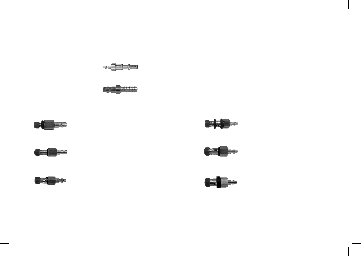
END-OF-LINE AND BANJO BOLT ADAPTERS
JC0180-1456 --- M6 Banjo Bolt
with O-ring
JC0180-1457 --- M8 Banjo Bolt
with Washer
JC0180-1458 --- M10 Banjo Bolt
with Washer
JC0180-1459 -- M12 X 1.25
Banjo Bolt
JC0180-1460 ---- M12 X 1.5
Banjo Bolt
JC0180-1447 ---- M14 X 1.5
Banjo Bolt
JC0180-1464 --- Single End Hose Adapter
20
JC0180-1440 --- Quick Connect Plug to
1/4” Hose

©2007 Matco Tools
Matco P/N
JC0002-3021
Stow, Ohio 44224
www.matcotools.com