
PORTABLE INVERTER GENERATOR
Owner’s Manual
P/N: 32082-07126-00
Model:
Serial:
Date Purchased:
SAVE THIS MANUAL FOR FUTURE REFERENCE
DO NOT RETURN
TO STORE!
CALL US FIRST
855-888-3598
FOR SUPPORT
Model# 1491012 REV00
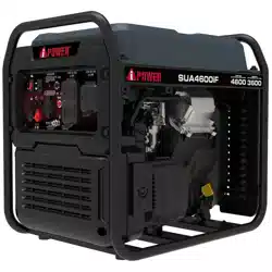
SUA4600iF
Introduction..........................................1
Safety....................................................1
General Safety Precautions....................2
Safety and Dataplate Labels..................8
Unpacking the Generator.......................9
Parts Included........................................9
Controls and Features...........................10
Control Panel Features.........................11
Specifications......................................13
CO WATCH-GUARD..............................14
Add Engine Oil......................................16
Low Oil Shutdown................................16
Add Fuel...............................................15
Operation at High Altitude......................17
Grounding............................................17
Connecting to a Building’s Electrical System...17
Operation.............................................18
Generator Location...............................18
Surge Protection...................................18
Starting the Generator...........................18
Connecting Electrical Loads..................19
Stopping the Engine..............................20
Low Idle Switch....................................20
Low Oil Shutdown................................21
Do Not Overload Generator....................21
Parallel Operation.................................20
Maintenance And Storage....................23
Maintenance Schedule.........................23
Engine Maintenance.............................23
Engine Oil Level Check.........................23
Change Engine Oil................................24
Air Filter Maintenance...........................25
Spark Plug Maintenance.......................25
Valve Clearance...................................25
Cleaning the Spark Arrestor..................26
Generator Maintenance.........................26
Storage................................................26
Trouble Shooting..................................27
Parts Diagram and Parts List................28
Parts Diagram......................................28
Parts List.............................................29
Circuit Diagram....................................33
Warranty..............................................34
Table of Contents
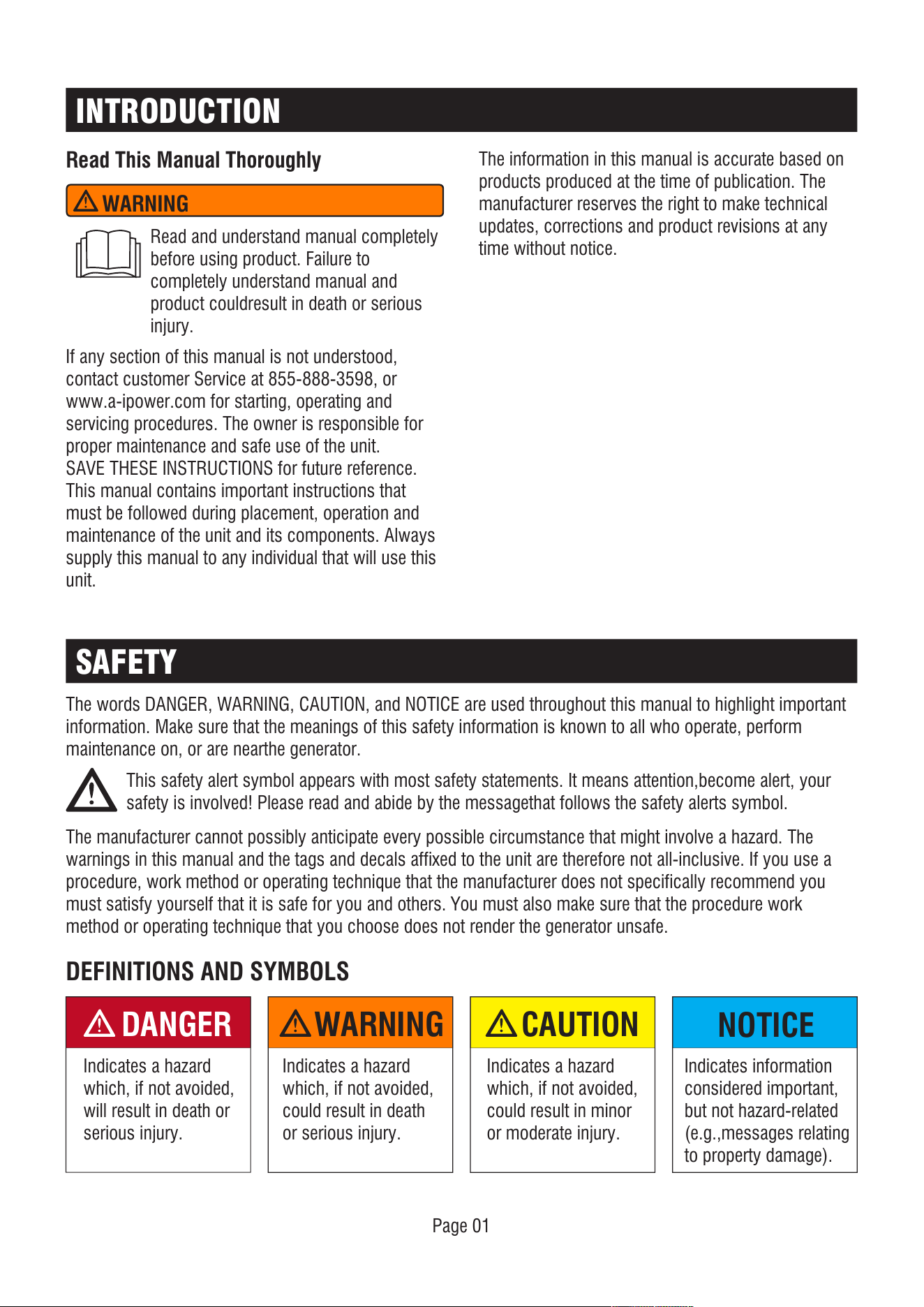
INTRODUCTION
SAFETY
Read This Manual Thoroughly
The manufacturer cannot possibly anticipate every possible circumstance that might involve a hazard. The
warnings in this manual and the tags and decals affixed to the unit are therefore not all-inclusive. If you use a
procedure, work method or operating technique that the manufacturer does not specifically recommend you
must satisfy yourself that it is safe for you and others. You must also make sure that the procedure work
method or operating technique that you choose does not render the generator unsafe.
If any section of this manual is not understood,
contact customer Service at 855-888-3598, or
www.a-ipower.com for starting, operating and
servicing procedures. The owner is responsible for
proper maintenance and safe use of the unit.
SAVE THESE INSTRUCTIONS for future reference.
This manual contains important instructions that
must be followed during placement, operation and
maintenance of the unit and its components. Always
supply this manual to any individual that will use this
unit.
The information in this manual is accurate based on
products produced at the time of publication. The
manufacturer reserves the right to make technical
updates, corrections and product revisions at any
time without notice.
Page 01
DEFINITIONS AND SYMBOLS
DANGER
Indicates a hazard
which, if not avoided,
will result in death or
serious injury.
WARNING
Indicates a hazard
which, if not avoided,
could result in death
or serious injury.
NOTICE
Indicates information
considered important,
but not hazard-related
(e.g.,messages relating
to property damage).
CAUTION
Indicates a hazard
which, if not avoided,
could result in minor
or moderate injury.
WARNING
Read and understand manual completely
before using product. Failure to
completely understand manual and
product couldresult in death or serious
injury.
The words DANGER, WARNING, CAUTION, and NOTICE are used throughout this manual to highlight important
information. Make sure that the meanings of this safety information is known to all who operate, perform
maintenance on, or are nearthe generator.
This safety alert symbol appears with most safety statements. It means attention,become alert, your
safety is involved! Please read and abide by the messagethat follows the safety alerts symbol.
Engine exhaust contains carbon
monoxide, a poisonous gas that could
kill you in minutes. You CANNOT smell
it, see it, or taste it. Even if you do not
smell exhaust fumes, you could still be
exposed to carbon monoxide gas.
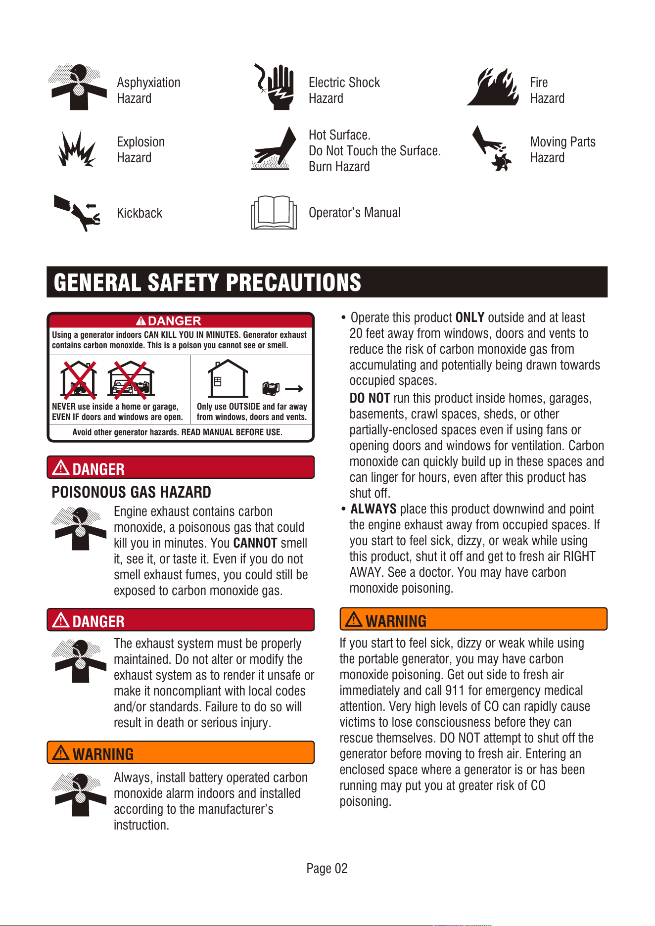
Asphyxiation
Hazard
Fire
Hazard
Hot Surface.
Do Not Touch the Surface.
Burn Hazard
Page 02
Kickback
Electric Shock
Hazard
Explosion
Hazard
Moving Parts
Hazard
Operator’s Manual
GENERAL SAFETY PRECAUTIONS
POISONOUS GAS HAZARD
DANGER
Using a generator indoors CAN KILL YOU IN MINUTES. Generator exhaust
contains carbon monoxide. This is a poison you cannot see or smell.
NEVER use inside a home or garage,
EVEN IF doors and windows are open.
Avoid other generator hazards. READ MANUAL BEFORE USE.
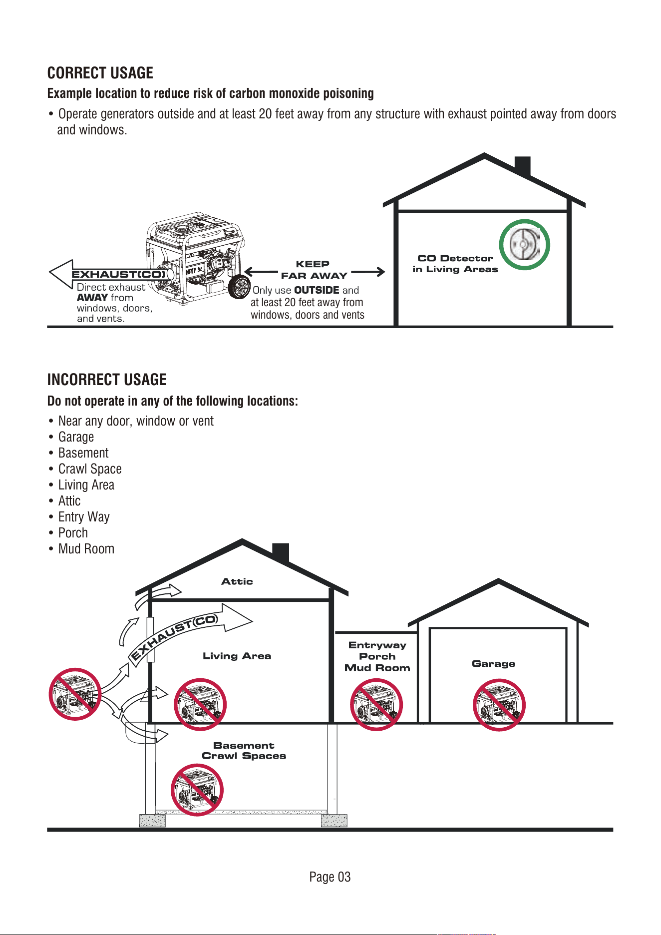
Only use OUTSIDE and far away
from windows, doors and vents.
The exhaust system must be properly
maintained. Do not alter or modify the
exhaust system as to render it unsafe or
make it noncompliant with local codes
and/or standards. Failure to do so will
result in death or serious injury.
DANGER
Always, install battery operated carbon
monoxide alarm indoors and installed
according to the manufacturer’s
instruction.
• Operate this product ONLY outside and at least
20 feet away from windows, doors and vents to
reduce the risk of carbon monoxide gas from
accumulating and potentially being drawn towards
occupied spaces.
DO NOT run this product inside homes, garages,
basements, crawl spaces, sheds, or other
partially-enclosed spaces even if using fans or
opening doors and windows for ventilation. Carbon
monoxide can quickly build up in these spaces and
can linger for hours, even after this product has
shut off.
• ALWAYS place this product downwind and point
the engine exhaust away from occupied spaces. If
you start to feel sick, dizzy, or weak while using
this product, shut it off and get to fresh air RIGHT
AWAY. See a doctor. You may have carbon
monoxide poisoning.
WARNING
If you start to feel sick, dizzy or weak while using
the portable generator, you may have carbon
monoxide poisoning. Get out side to fresh air
immediately and call 911 for emergency medical
attention. Very high levels of CO can rapidly cause
victims to lose consciousness before they can
rescue themselves. DO NOT attempt to shut off the
generator before moving to fresh air. Entering an
enclosed space where a generator is or has been
running may put you at greater risk of CO
poisoning.
WARNING
Page 03
• Operate generators outside and at least 20 feet away from any structure with exhaust pointed away from doors
and windows.
CORRECT USAGE
INCORRECT USAGE
Example location to reduce risk of carbon monoxide poisoning
• Near any door, window or vent
• Garage
• Basement
• Crawl Space
• Living Area
• Attic
• Entry Way
• Porch
• Mud Room
Do not operate in any of the following locations:
at least 20 feet away from
windows, doors and vents
Page 04
• When starting engine, pull cord slowly until
resistance is felt and then pull rapidly to avoid
kickback.
• NEVER start or stop engine with electrical devices
plugged in and turned on.
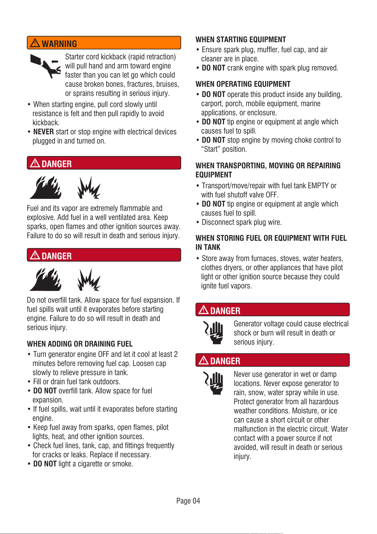
Starter cord kickback (rapid retraction)
will pull hand and arm toward engine
faster than you can let go which could
cause broken bones, fractures, bruises,
or sprains resulting in serious injury.
WARNING
DANGER
WHEN ADDING OR DRAINING FUEL
• Turn generator engine OFF and let it cool at least 2
minutes before removing fuel cap. Loosen cap
slowly to relieve pressure in tank.
• Fill or drain fuel tank outdoors.
• DO NOT overfill tank. Allow space for fuel
expansion.
• If fuel spills, wait until it evaporates before starting
engine.
• Keep fuel away from sparks, open flames, pilot
lights, heat, and other ignition sources.
• Check fuel lines, tank, cap, and fittings frequently
for cracks or leaks. Replace if necessary.
• DO NOT light a cigarette or smoke.
WHEN STARTING EQUIPMENT
• Ensure spark plug, muffler, fuel cap, and air
cleaner are in place.
• DO NOT crank engine with spark plug removed.
WHEN OPERATING EQUIPMENT
• DO NOT operate this product inside any building,
carport, porch, mobile equipment, marine
applications, or enclosure.
• DO NOT tip engine or equipment at angle which
causes fuel to spill.
• DO NOT stop engine by moving choke control to
“Start” position.
Fuel and its vapor are extremely flammable and
explosive. Add fuel in a well ventilated area. Keep
sparks, open flames and other ignition sources away.
Failure to do so will result in death and serious injury.
DANGER
DANGER
Do not overfill tank. Allow space for fuel expansion. If
fuel spills wait until it evaporates before starting
engine. Failure to do so will result in death and
serious injury.
WHEN TRANSPORTING, MOVING OR REPAIRING
EQUIPMENT
• Transport/move/repair with fuel tank EMPTY or
with fuel shutoff valve OFF.
• DO NOT tip engine or equipment at angle which
causes fuel to spill.
• Disconnect spark plug wire.
WHEN STORING FUEL OR EQUIPMENT WITH FUEL
IN TANK
• Store away from furnaces, stoves, water heaters,
clothes dryers, or other appliances that have pilot
light or other ignition source because they could
ignite fuel vapors.
Generator voltage could cause electrical
shock or burn will result in death or
serious injury.
DANGER
Never use generator in wet or damp
locations. Never expose generator to
rain, snow, water spray while in use.
Protect generator from all hazardous
weather conditions. Moisture, or ice
can cause a short circuit or other
malfunction in the electric circuit. Water
contact with a power source if not
avoided, will result in death or serious
injury.
WARNING
WARNING
WARNING
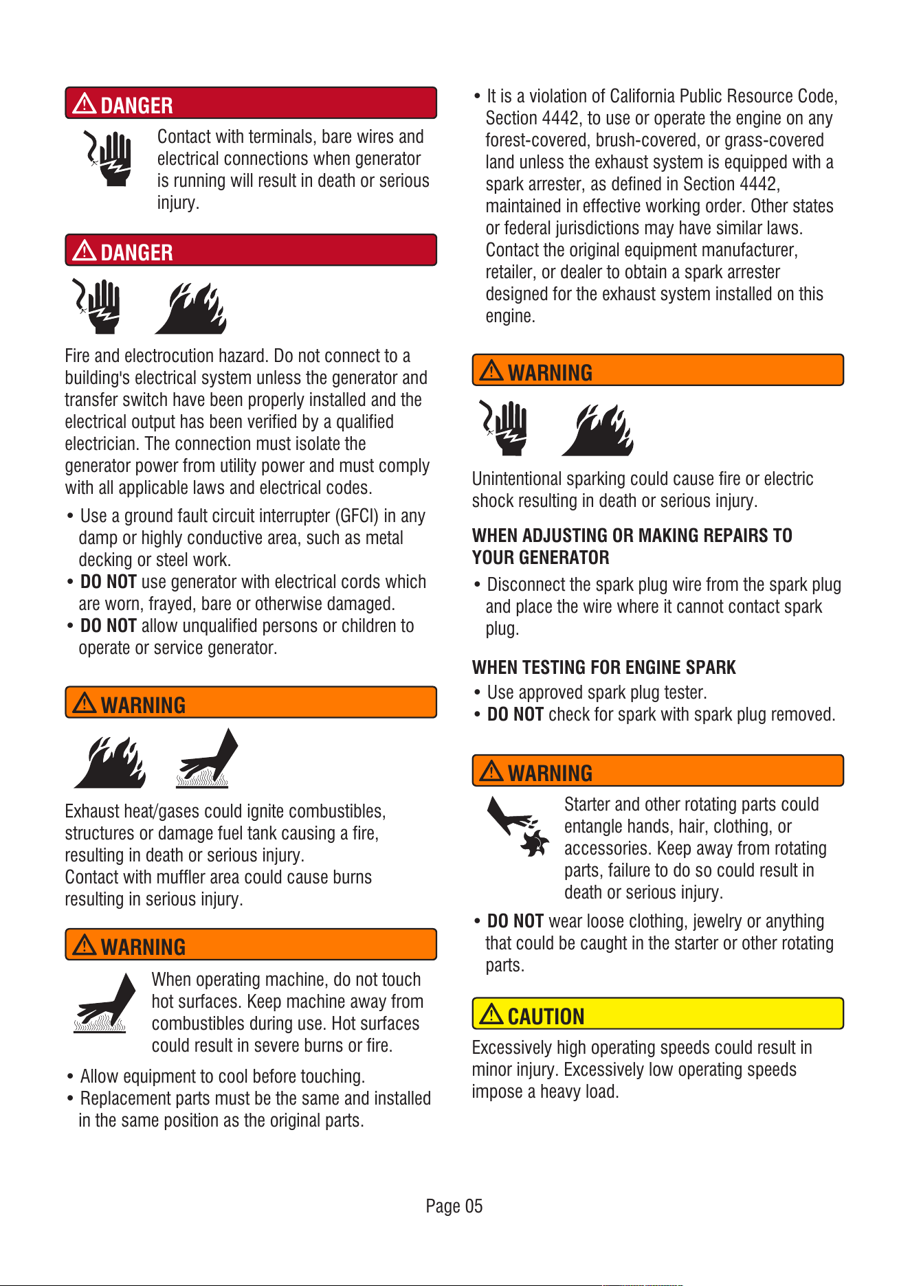
When operating machine, do not touch
hot surfaces. Keep machine away from
combustibles during use. Hot surfaces
could result in severe burns or fire.
WARNING
• Use a ground fault circuit interrupter (GFCI) in any
damp or highly conductive area, such as metal
decking or steel work.
• DO NOT use generator with electrical cords which
are worn, frayed, bare or otherwise damaged.
• DO NOT allow unqualified persons or children to
operate or service generator.
DANGER
Contact with terminals, bare wires and
electrical connections when generator
is running will result in death or serious
injury.
DANGER
WHEN ADJUSTING OR MAKING REPAIRS TO
YOUR GENERATOR
• Disconnect the spark plug wire from the spark plug
and place the wire where it cannot contact spark
plug.
WHEN TESTING FOR ENGINE SPARK
• Use approved spark plug tester.
• DO NOT check for spark with spark plug removed.
Exhaust heat/gases could ignite combustibles,
structures or damage fuel tank causing a fire,
resulting in death or serious injury.
Contact with muffler area could cause burns
resulting in serious injury.
• It is a violation of California Public Resource Code,
Section 4442, to use or operate the engine on any
forest-covered, brush-covered, or grass-covered
land unless the exhaust system is equipped with a
spark arrester, as defined in Section 4442,
maintained in effective working order. Other states
or federal jurisdictions may have similar laws.
Contact the original equipment manufacturer,
retailer, or dealer to obtain a spark arrester
designed for the exhaust system installed on this
engine.
• Allow equipment to cool before touching.
• Replacement parts must be the same and installed
in the same position as the original parts.
• DO NOT wear loose clothing, jewelry or anything
that could be caught in the starter or other rotating
parts.
Starter and other rotating parts could
entangle hands, hair, clothing, or
accessories. Keep away from rotating
parts, failure to do so could result in
death or serious injury.
Unintentional sparking could cause fire or electric
shock resulting in death or serious injury.
Fire and electrocution hazard. Do not connect to a
building's electrical system unless the generator and
transfer switch have been properly installed and the
electrical output has been verified by a qualified
electrician. The connection must isolate the
generator power from utility power and must comply
with all applicable laws and electrical codes.
Excessively high operating speeds could result in
minor injury. Excessively low operating speeds
impose a heavy load.
CAUTION
Page 05
Page 06
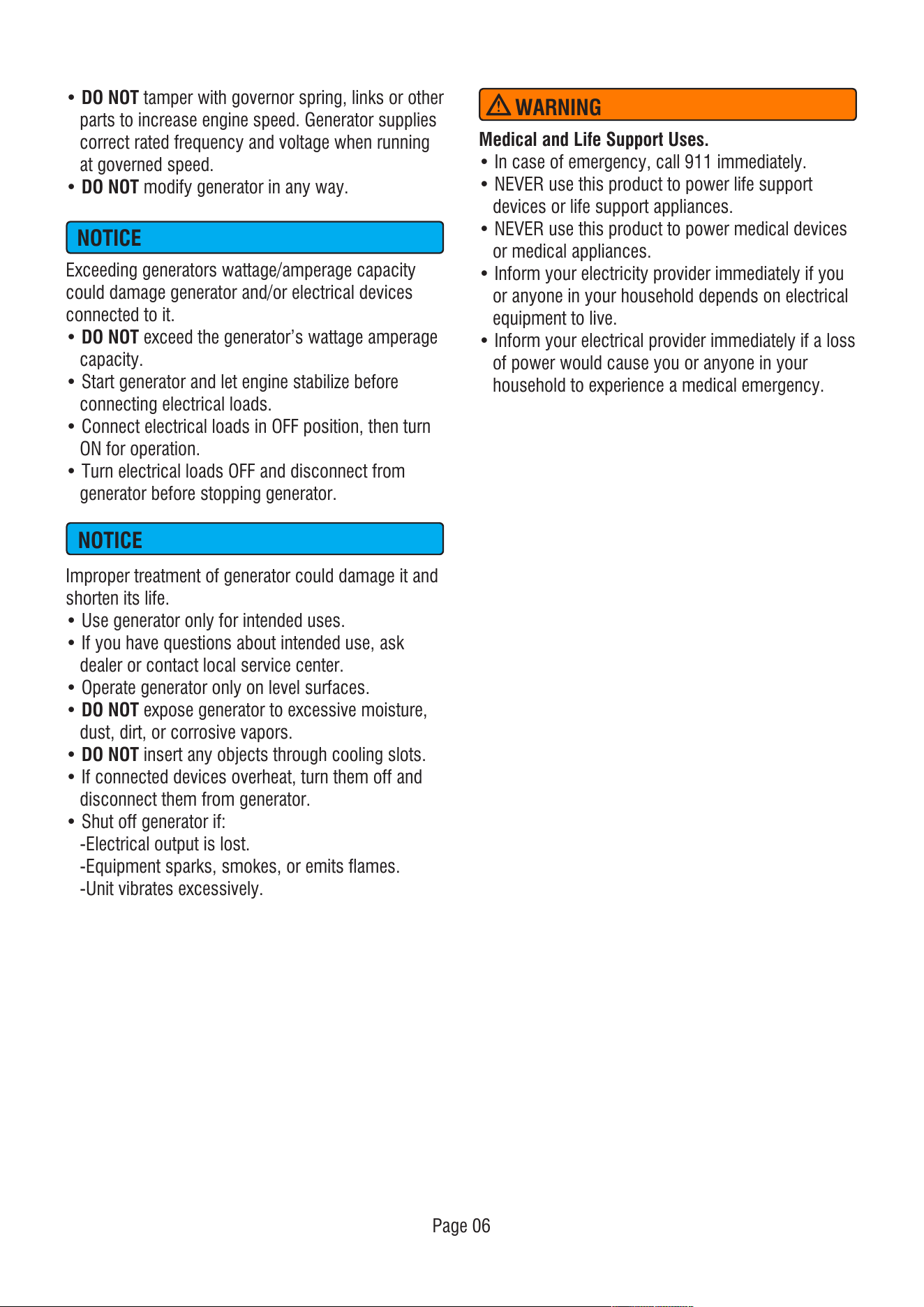
• DO NOT tamper with governor spring, links or other
parts to increase engine speed. Generator supplies
correct rated frequency and voltage when running
at governed speed.
• DO NOT modify generator in any way.
Exceeding generators wattage/amperage capacity
could damage generator and/or electrical devices
connected to it.
• DO NOT exceed the generator’s wattage amperage
capacity.
• Start generator and let engine stabilize before
connecting electrical loads.
• Connect electrical loads in OFF position, then turn
ON for operation.
• Turn electrical loads OFF and disconnect from
generator before stopping generator.
NOTICE
NOTICE
Improper treatment of generator could damage it and
shorten its life.
• Use generator only for intended uses.
• If you have questions about intended use, ask
dealer or contact local service center.
• Operate generator only on level surfaces.
• DO NOT expose generator to excessive moisture,
dust, dirt, or corrosive vapors.
• DO NOT insert any objects through cooling slots.
• If connected devices overheat, turn them off and
disconnect them from generator.
• Shut off generator if:
-Electrical output is lost.
-Equipment sparks, smokes, or emits flames.
-Unit vibrates excessively.
Medical and Life Support Uses.
• In case of emergency, call 911 immediately.
• NEVER use this product to power life support
devices or life support appliances.
• NEVER use this product to power medical devices
or medical appliances.
• Inform your electricity provider immediately if you
or anyone in your household depends on electrical
equipment to live.
• Inform your electrical provider immediately if a loss
of power would cause you or anyone in your
household to experience a medical emergency.
WARNING
Page 07
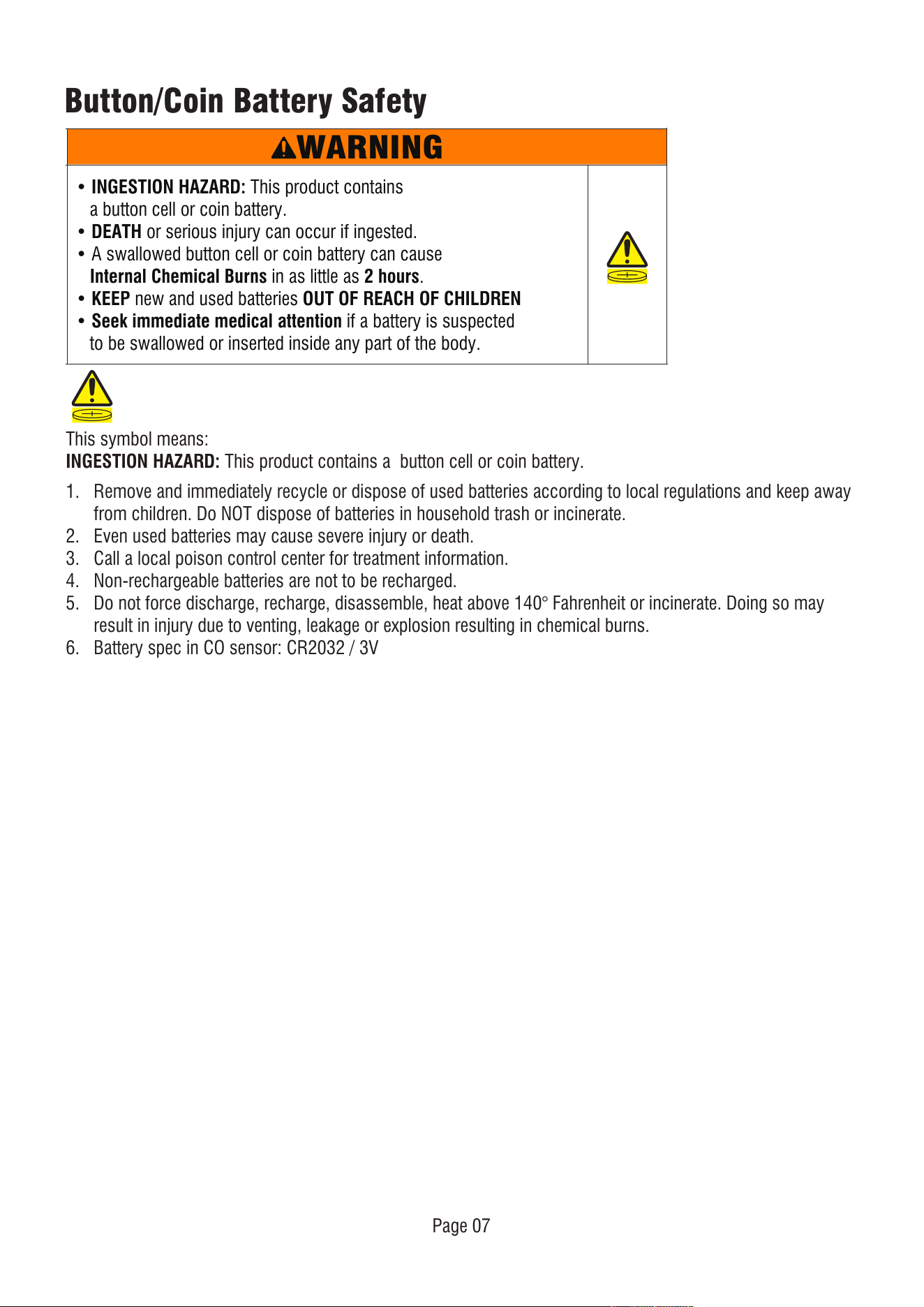
Button/Coin Battery Safety
WARNING
This symbol means:
INGESTION HAZARD: This product contains a button cell or coin battery.
• INGESTION HAZARD: This product contains
a button cell or coin battery.
• DEATH or serious injury can occur if ingested.
• A swallowed button cell or coin battery can cause
Internal Chemical Burns in as little as 2 hours.
• KEEP new and used batteries OUT OF REACH OF CHILDREN
• Seek immediate medical attention if a battery is suspected
to be swallowed or inserted inside any part of the body.
1. Remove and immediately recycle or dispose of used batteries according to local regulations and keep away
from children. Do NOT dispose of batteries in household trash or incinerate.
2. Even used batteries may cause severe injury or death.
3. Call a local poison control center for treatment information.
4. Non-rechargeable batteries are not to be recharged.
5. Do not force discharge, recharge, disassemble, heat above 140° Fahrenheit or incinerate. Doing so may
result in injury due to venting, leakage or explosion resulting in chemical burns.
6. Battery spec in CO sensor: CR2032 / 3V
Page 08
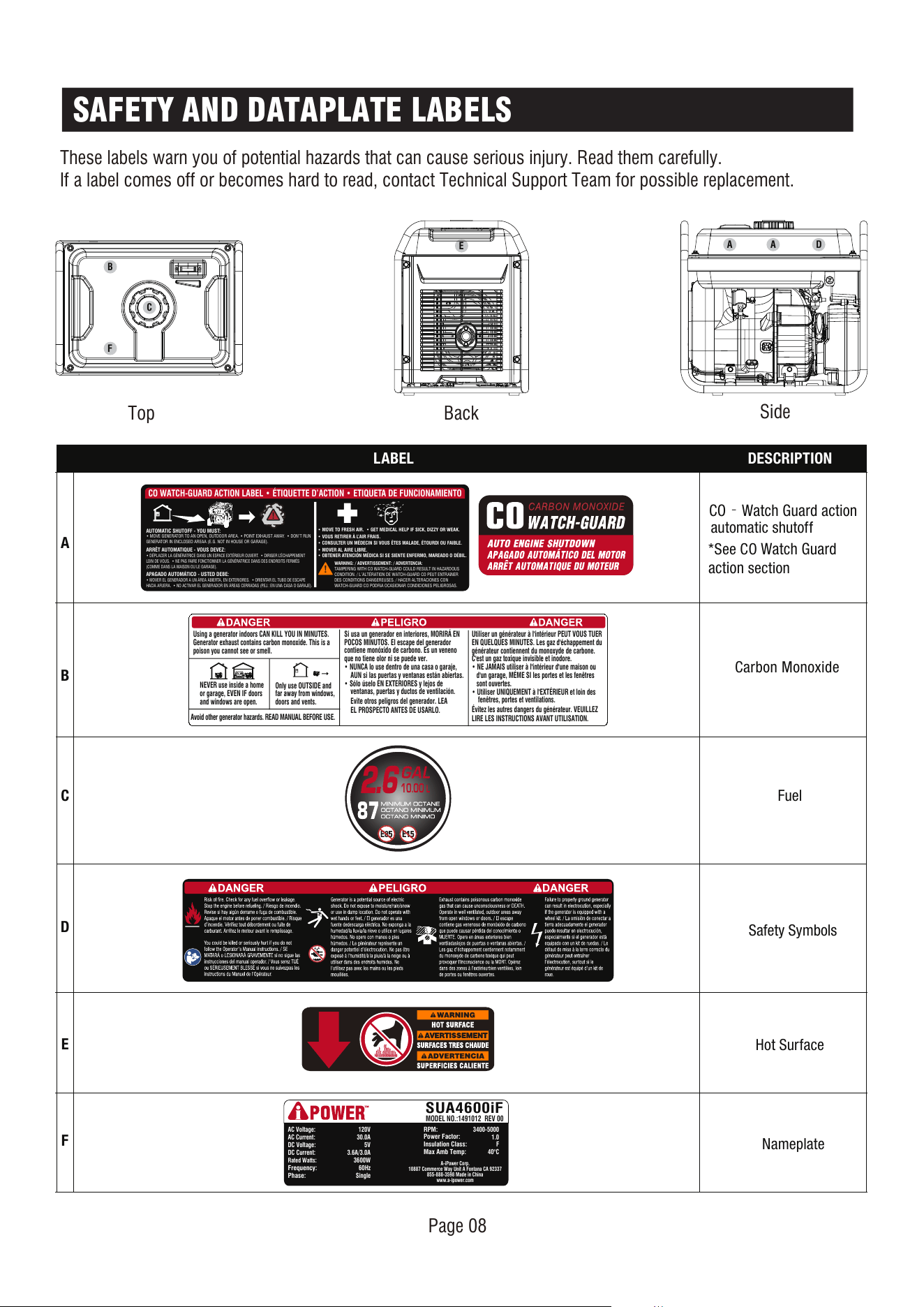
SAFETY AND DATAPLATE LABELS
These labels warn you of potential hazards that can cause serious injury. Read them carefully.
If a label comes off or becomes hard to read, contact Technical Support Team for possible replacement.
LABEL DESCRIPTION
A
B
Carbon Monoxide
C
Fuel
D
Hot Surface
E
F
Nameplate
Safety Symbols
CO‐Watch Guard action
automatic shutoff
*See CO
Watch Guard
action
section
AUTOMATIC SHUTOFF - YOU MUST:
• MOVE GENERATOR TO AN OPEN, OUTDOOR AREA. • POINT EXHAUST AWAY. • DON’T RUN
GENERATOR IN ENCLOSED AREAA (E.G. NOT IN HOUSE OR GARAGE).
CO WATCH-GUARD ACTION LABEL • ÉTIQUETTE D’ACTION • ETIQUETA DE FUNCIONAMIENTO
ARRÊT AUTOMATIQUE - VOUS DEVEZ:
• DÉPLACER LA GÉNÉRATRICE DANS UN ESPACE EXTÉRIEUR OUVERT. • DIRIGER L’ÉCHAPPEMENT
LOIN DE VOUS. • NE PAS FAIRE FONCTIONNER LA GÉNÉRATRICE DANS DES ENDROITS FERMÉS
(COMME DANS LA MAISON OU LE GARAGE).
• MOVE TO FRESH AIR. • GET MEDICAL HELP IF SICK, DIZZY OR WEAK.
WARNING: / ADVERTISSEMENT: / ADVERTENCIA:
TAMPERING WITH CO WATCH-GUARD COULD RESULT IN HAZARDOUS
CONDITION. / L’ALTÉRATION DE WATCH-GUARD CO PEUT ENTRAîNER
DES CONDITIONS DANGEREUSES. / HACER ALTERACIONES CON
WATCH-GUARD CO PODRíA OCASIONAR CONDICIONES PELIGROSAS.
• VOUS RETIRER À L’AIR FRAIS.
• CONSULTER UN MÉDECIN SI VOUS ÊTES MALADE, ÉTOURDI OU FAIBLE.
• MOVER AL AIRE LIBRE.
• OBTENER ATENCIÓN MÉDICA SI SE SIENTE ENFERMO, MAREADO O DÉBIL.
APAGADO AUTOMÁTICO - USTED DEBE:
• MOVER EL GENERADOR A UN ÁREA ABIERTA, EN EXTERIORES. • ORIENTAR EL TUBO DE ESCAPE
HACIA AFUERA. • NO ACTIVAR EL GENERADOR EN ÁREAS CERRADAS (P.EJ.: EN UNA CASA O GARAJE).
Avoid other generator hazards. READ MANUAL BEFORE USE.
Using a generator indoors CAN KILL YOU IN MINUTES.
Generator exhaust contains carbon monoxide. This is a
poison you cannot see or smell.
NEVER use inside a home
or garage, EVEN IF doors
and windows are open.
Only use OUTSIDE and
far away from windows,
doors and vents.
Si usa un generador en interiores, MORIRÁ EN
POCOS MINUTOS. El escape del generador
contiene monóxido de carbono. Es un veneno
que no tiene olor ni se puede ver.
• NUNCA lo use dentro de una casa o garaje,
AUN si las puertas y ventanas están abiertas.
• Sólo úselo EN EXTERIORES y lejos de
ventanas, puertas y ductos de ventilación.
Evite otros peligros del generador. LEA
EL PROSPECTO ANTES DE USARLO.
Utiliser un générateur à l'intérieur PEUT VOUS TUER
EN QUELQUES MINUTES. Les gaz d'échappement du
générateur contiennent du monoxyde de carbone.
C'est un gaz toxique invisible et inodore.
• NE JAMAIS utiliser à l'intérieur d'une maison ou
d'un garage, MÉME SI les portes et les fenêtres
sont ouvertes.
• Utiliser UNIQUEMENT à l'EXTÉRIEUR et loin des
fenêtres, portes et ventilations.
Évitez les autres dangers du générateur. VEUILLEZ
LIRE LES INSTRUCTIONS AVANT UTILISATION.
10.00
L
2.6
B
F
Top Back
Side
C
E
A A D
Frequency:
60Hz
AC Voltage: 120V
AC Current: 30.0A
DC Voltage:
5V
DC Current:
3.6A/3.0A
Rated Watts
:
3600W
Phase:
Single
Insulation Class:
RPM:
Power Factor:
F
3400-5000
1.0
Max Amb Temp:
40°C
A-iPower Corp.
10887 Commerce Way Unit A Fontana CA 92337
855-888-3598 Made in China
www.a-ipower.com
MODEL NO.:1491012 REV 00
SUA4600iF
Page 09
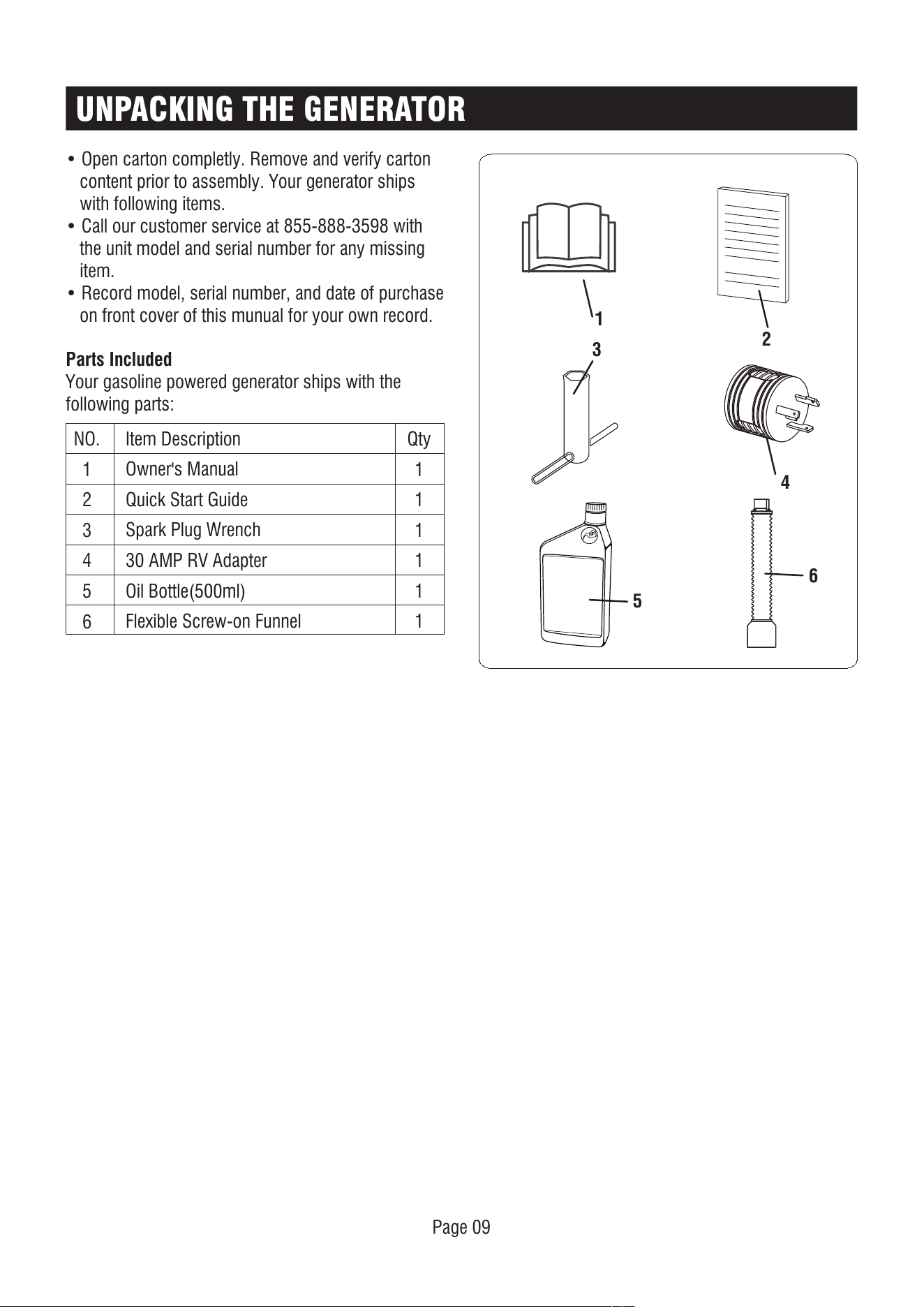
UNPACKING THE GENERATOR
Parts Included
Your gasoline powered generator ships with the
following parts:
• Open carton completly. Remove and verify carton
content prior to assembly. Your generator ships
with following items.
• Call our customer service at 855-888-3598 with
the unit model and serial number for any missing
item.
• Record model, serial number, and date of purchase
on front cover of this munual for your own record.
1
2
6
5
NO.
1
2
3
4
5
6
Qty
1
1
1
1
1
1
Item Description
Owner's Manual
Quick Start Guide
Spark Plug Wrench
30 AMP RV Adapter
Oil Bottle(500ml)
Flexible Screw-on Funnel
4
3
Page 10
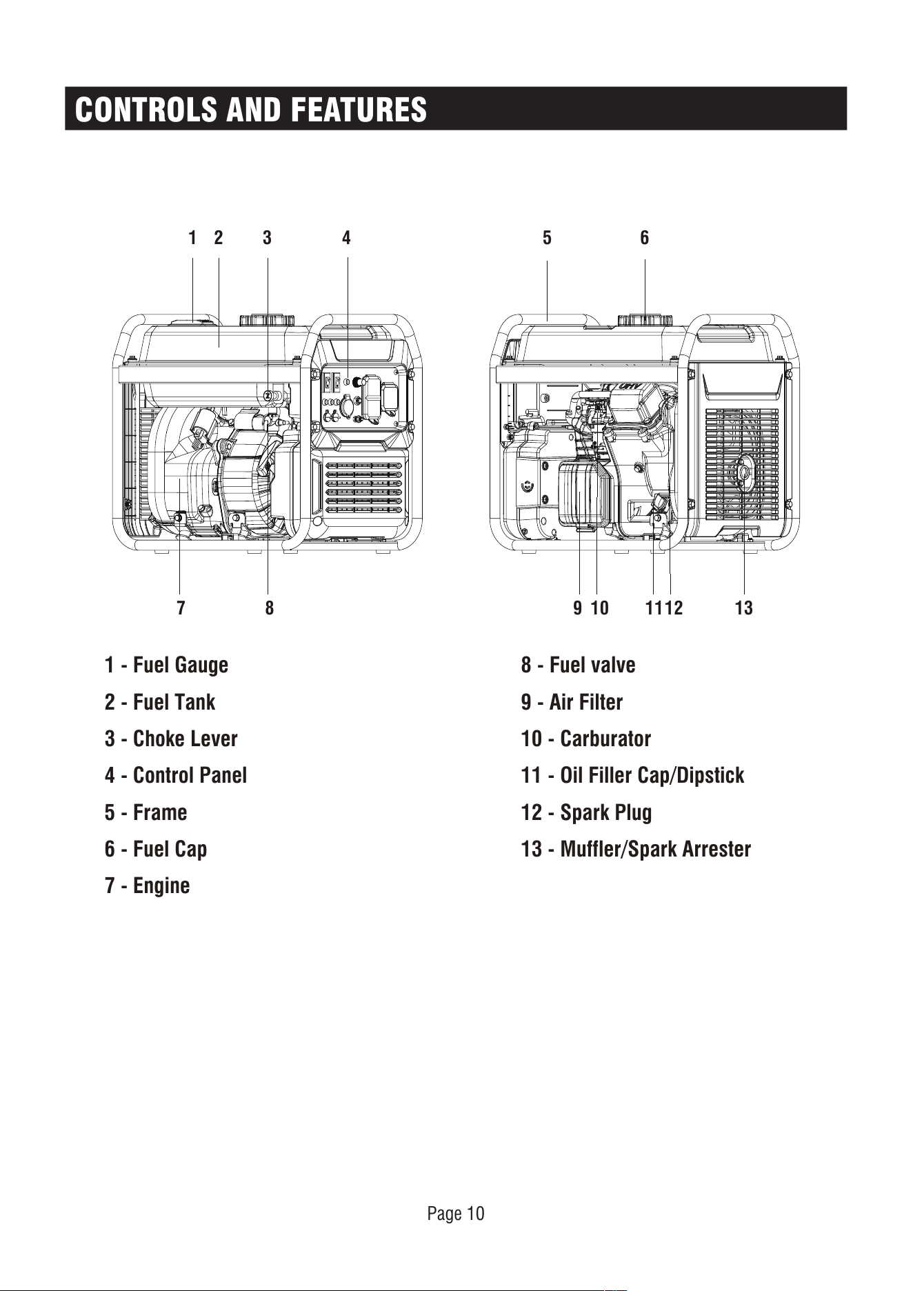
CONTROLS AND FEATURES
1 - Fuel Gauge
2 - Fuel Tank
3 - Choke Lever
4 - Control Panel
5 - Frame
6 - Fuel Cap
7 - Engine
8 - Fuel valve
9 - Air Filter
10 - Carburator
11 - Oil Filler Cap/Dipstick
12 - Spark Plug
13 - Muffler/Spark Arrester
21
139 10 1112
6
87
43 5
Page 11
CONTROL PANEL FEATURES
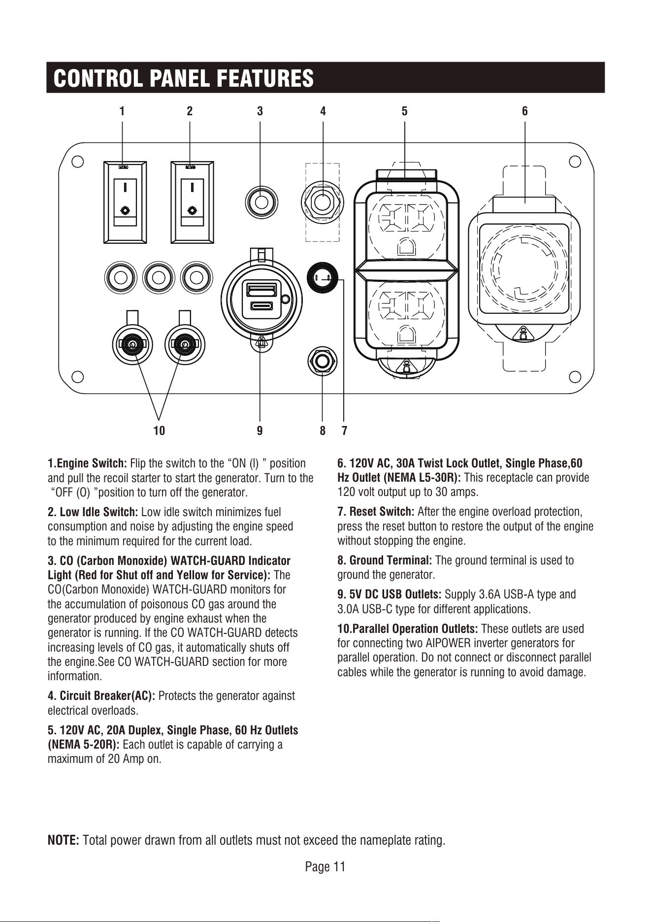
NOTE: Total power drawn from all outlets must not exceed the nameplate rating.
1 2 3 4 5 6
7810 9
DAIMAO DAIMAO
1.Engine Switch: Flip the switch to the “ON (l) ” position
and pull the recoil starter to start the generator. Turn to the
“OFF (O) ”position to turn off the generator.
2. Low Idle Switch: Low idle switch minimizes fuel
consumption and noise by adjusting the engine speed
to the minimum required for the current load.
3. CO (Carbon Monoxide) WATCH-GUARD Indicator
Light (Red for Shut off and Yellow for Service): The
CO(Carbon Monoxide) WATCH-GUARD monitors for
the accumulation of poisonous CO gas around the
generator produced by engine exhaust when the
generator is running. If the CO WATCH-GUARD detects
increasing levels of CO gas, it automatically shuts off
the engine.See CO WATCH-GUARD section for more
information.
4. Circuit Breaker(AC): Protects the generator against
electrical overloads.
5. 120V AC, 20A Duplex, Single Phase, 60 Hz Outlets
(NEMA 5-20R): Each outlet is capable of carrying a
maximum of 20 Amp on.
6. 120V AC, 30A Twist Lock Outlet, Single Phase,60
Hz Outlet (NEMA L5-30R): This receptacle can provide
120 volt output up to 30 amps.
7. Reset Switch: After the engine overload protection,
press the reset button to restore the output of the engine
without stopping the engine.
8. Ground Terminal: The ground terminal is used to
ground the generator.
9. 5V DC USB Outlets: Supply 3.6A USB-A type and
3.0A USB-C type for different applications.
10.Parallel Operation Outlets: These outlets are used
for connecting two AIPOWER inverter generators for
parallel operation. Do not connect or disconnect parallel
cables while the generator is running to avoid damage.
CONTROL PANEL FEATURES
Page 12
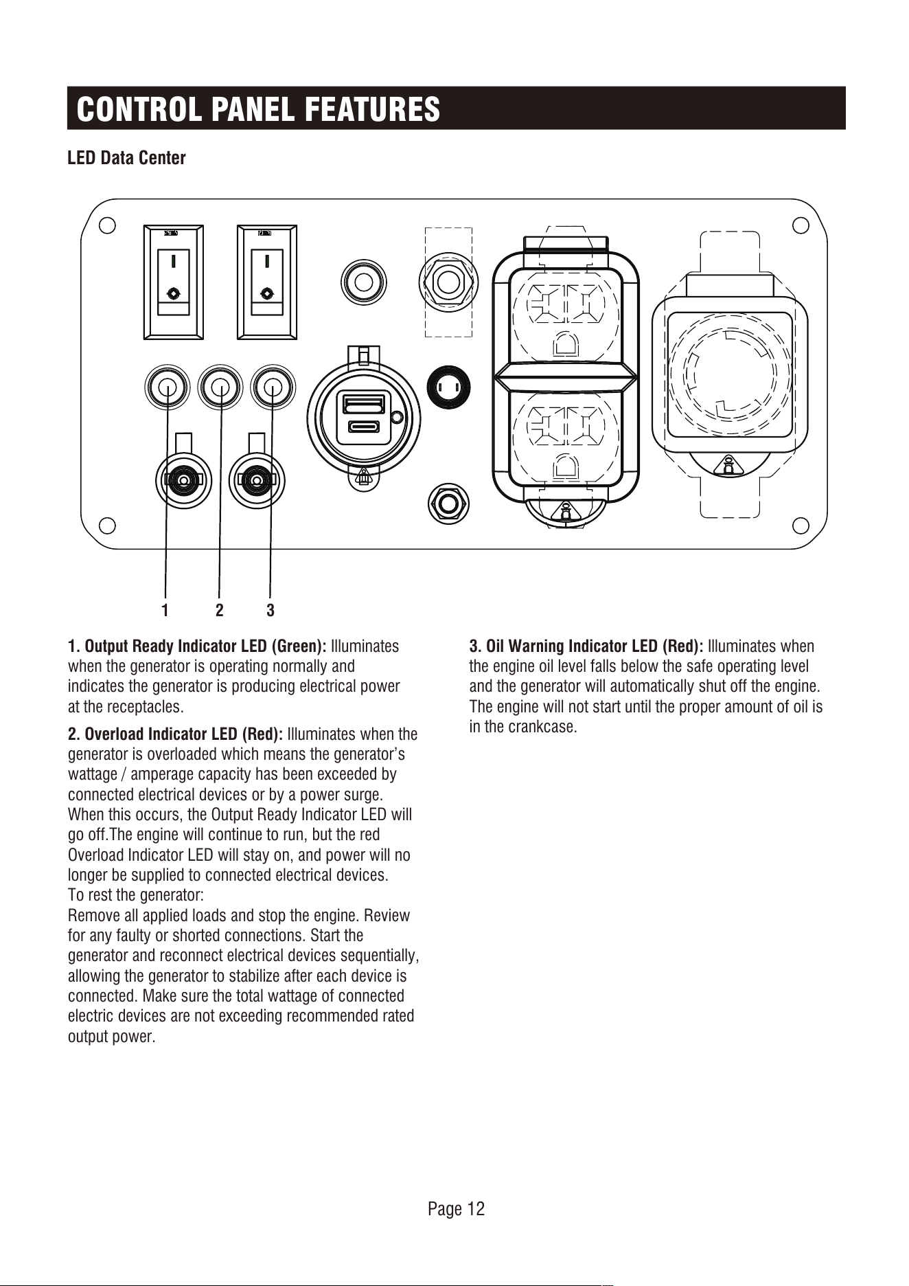
LED Data Center
DAIMAO DAIMAO
1 32
1. Output Ready Indicator LED (Green): Illuminates
when the generator is operating normally and
indicates the generator is producing electrical power
at the receptacles.
2. Overload Indicator LED (Red): Illuminates when the
generator is overloaded which means the generator’s
wattage / amperage capacity has been exceeded by
connected electrical devices or by a power surge.
When this occurs, the Output Ready Indicator LED will
go off.The engine will continue to run, but the red
Overload Indicator LED will stay on, and power will no
longer be supplied to connected electrical devices.
To rest the generator:
Remove all applied loads and stop the engine. Review
for any faulty or shorted connections. Start the
generator and reconnect electrical devices sequentially,
allowing the generator to stabilize after each device is
connected. Make sure the total wattage of connected
electric devices are not exceeding recommended rated
output power.
3. Oil Warning Indicator LED (Red): Illuminates when
the engine oil level falls below the safe operating level
and the generator will automatically shut off the engine.
The engine will not start until the proper amount of oil is
in the crankcase.
Page 13
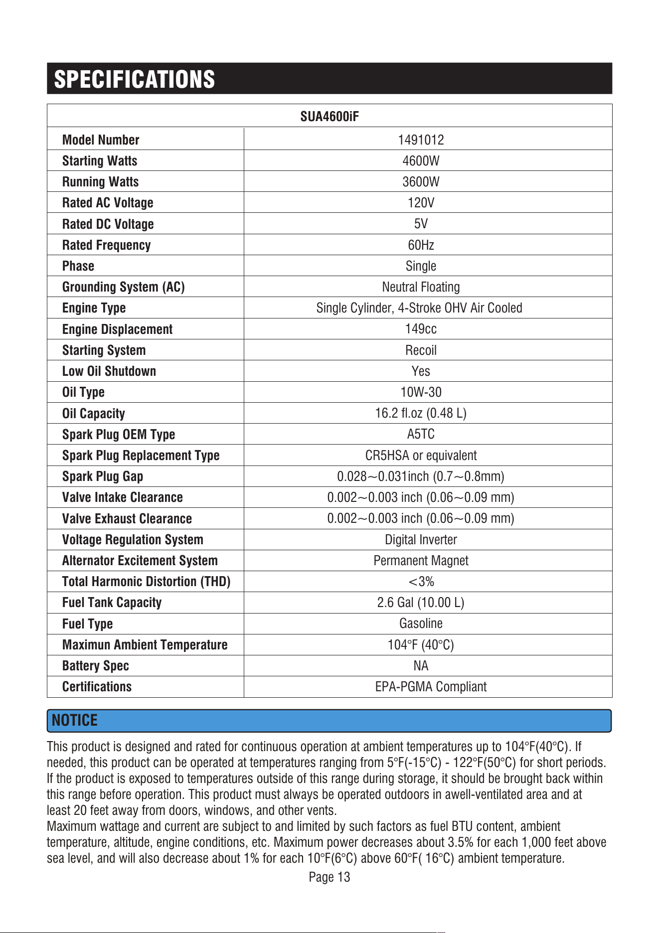
SPECIFICATIONS
SUA4600iF
Model Number
Starting Watts
Running Watts
Rated AC Voltage
Rated DC Voltage
Rated Frequency
Phase
Grounding System (AC)
Engine Type
Engine Displacement
Starting System
Low Oil Shutdown
Oil Type
Oil Capacity
Spark Plug OEM Type
Spark Plug Replacement Type
Spark Plug Gap
Valve Intake Clearance
Valve Exhaust Clearance
Voltage Regulation System
Alternator Excitement System
Total Harmonic Distortion (THD)
Fuel Tank Capacity
Fuel Type
Maximun Ambient Temperature
Battery Spec
Certifications
1491012
4600W
3600W
120V
5V
60Hz
Single
Neutral Floating
Single Cylinder, 4-Stroke OHV Air Cooled
149cc
Recoil
Yes
10W-30
16.2 fl.oz (0.48 L)
A5TC
CR5HSA or equivalent
0.028~0.031inch (0.7~0.8mm)
0.002~0.003 inch (0.06~0.09 mm)
0.002~0.003 inch (0.06~0.09 mm)
Digital Inverter
Permanent Magnet
<3%
2.6 Gal (10.00 L)
Gasoline
104°F (40°C)
NA
EPA-PGMA Compliant
NOTICE
This product is designed and rated for continuous operation at ambient temperatures up to 104°F(40°C). If
needed, this product can be operated at temperatures ranging from 5°F(-15°C) - 122°F(50°C) for short periods.
If the product is exposed to temperatures outside of this range during storage, it should be brought back within
this range before operation. This product must always be operated outdoors in awell-ventilated area and at
least 20 feet away from doors, windows, and other vents.
Maximum wattage and current are subject to and limited by such factors as fuel BTU content, ambient
temperature, altitude, engine conditions, etc. Maximum power decreases about 3.5% for each 1,000 feet above
sea level, and will also decrease about 1% for each 10°F(6°C) above 60°F( 16°C) ambient temperature.
Page 14
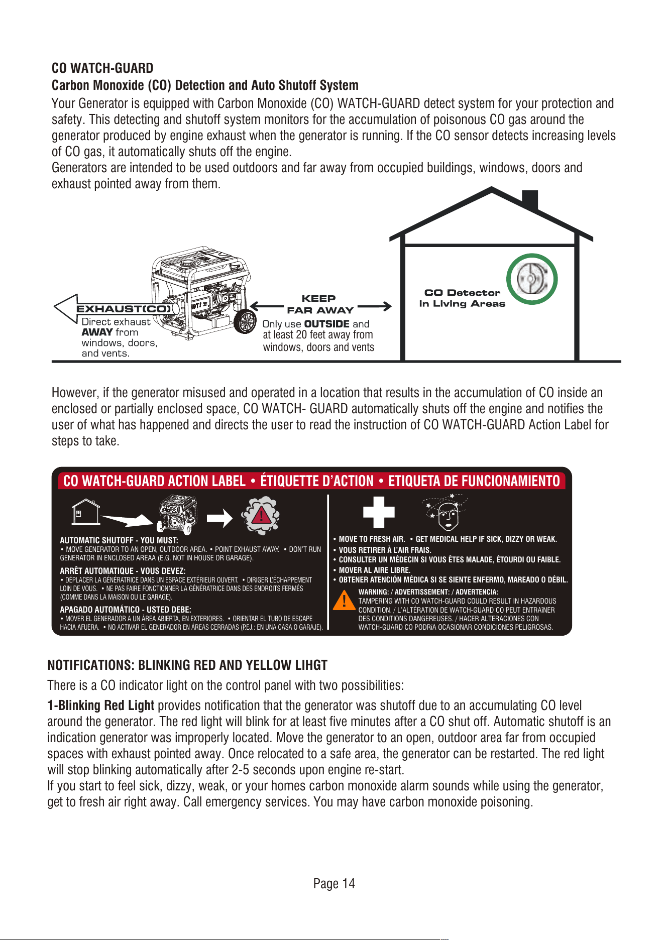
CO WATCH-GUARD
Carbon Monoxide (CO) Detection and Auto Shutoff System
Your Generator is equipped with Carbon Monoxide (CO) WATCH-GUARD detect system for your protection and
safety. This detecting and shutoff system monitors for the accumulation of poisonous CO gas around the
generator produced by engine exhaust when the generator is running. If the CO sensor detects increasing levels
of CO gas, it automatically shuts off the engine.
Generators are intended to be used outdoors and far away from occupied buildings, windows, doors and
exhaust pointed away from them.
However, if the generator misused and operated in a location that results in the accumulation of CO inside an
enclosed or partially enclosed space, CO WATCH- GUARD automatically shuts off the engine and notifies the
user of what has happened and directs the user to read the instruction of CO WATCH-GUARD Action Label for
steps to take.
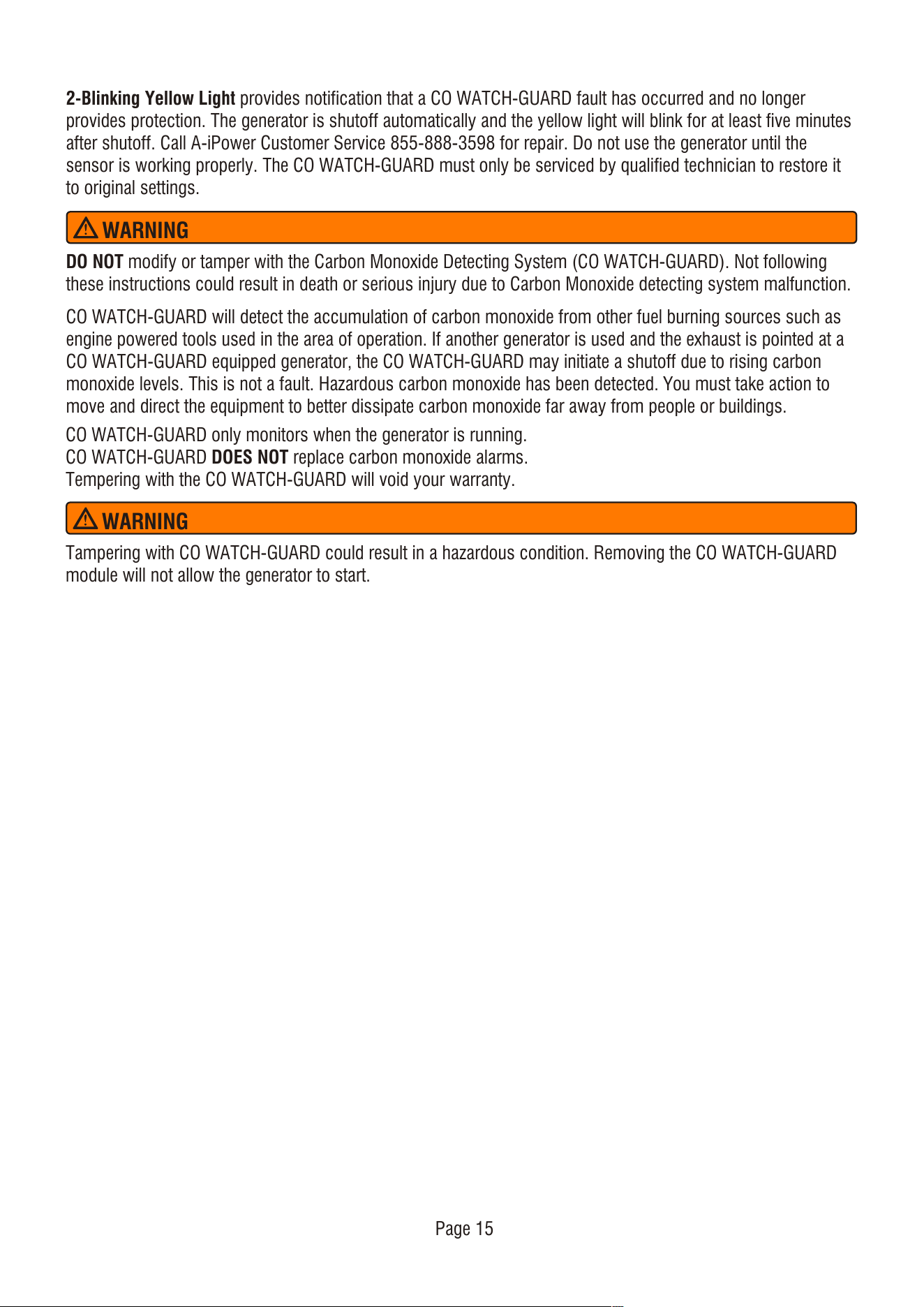
AUTOMATIC SHUTOFF - YOU MUST:
• MOVE GENERATOR TO AN OPEN, OUTDOOR AREA. • POINT EXHAUST AWAY. • DON’T RUN
GENERATOR IN ENCLOSED AREAA (E.G. NOT IN HOUSE OR GARAGE).
CO WATCH-GUARD ACTION LABEL • ÉTIQUETTE D’ACTION • ETIQUETA DE FUNCIONAMIENTO
ARRÊT AUTOMATIQUE - VOUS DEVEZ:
• DÉPLACER LA GÉNÉRATRICE DANS UN ESPACE EXTÉRIEUR OUVERT. • DIRIGER L’ÉCHAPPEMENT
LOIN DE VOUS. • NE PAS FAIRE FONCTIONNER LA GÉNÉRATRICE DANS DES ENDROITS FERMÉS
(COMME DANS LA MAISON OU LE GARAGE).
• MOVE TO FRESH AIR. • GET MEDICAL HELP IF SICK, DIZZY OR WEAK.
WARNING: / ADVERTISSEMENT: / ADVERTENCIA:
TAMPERING WITH CO WATCH-GUARD COULD RESULT IN HAZARDOUS
CONDITION. / L’ALTÉRATION DE WATCH-GUARD CO PEUT ENTRAîNER
DES CONDITIONS DANGEREUSES. / HACER ALTERACIONES CON
WATCH-GUARD CO PODRíA OCASIONAR CONDICIONES PELIGROSAS.
• VOUS RETIRER À L’AIR FRAIS.
• CONSULTER UN MÉDECIN SI VOUS ÊTES MALADE, ÉTOURDI OU FAIBLE.
• MOVER AL AIRE LIBRE.
• OBTENER ATENCIÓN MÉDICA SI SE SIENTE ENFERMO, MAREADO O DÉBIL.
APAGADO AUTOMÁTICO - USTED DEBE:
• MOVER EL GENERADOR A UN ÁREA ABIERTA, EN EXTERIORES. • ORIENTAR EL TUBO DE ESCAPE
HACIA AFUERA. • NO ACTIVAR EL GENERADOR EN ÁREAS CERRADAS (P.EJ.: EN UNA CASA O GARAJE).
NOTIFICATIONS: BLINKING RED AND YELLOW LIHGT
There is a CO indicator light on the control panel with two possibilities:
1-Blinking Red Light provides notification that the generator was shutoff due to an accumulating CO level
around the generator. The red light will blink for at least five minutes after a CO shut off. Automatic shutoff is an
indication generator was improperly located. Move the generator to an open, outdoor area far from occupied
spaces with exhaust pointed away. Once relocated to a safe area, the generator can be restarted. The red light
will stop blinking automatically after 2-5 seconds upon engine re-start.
If you start to feel sick, dizzy, weak, or your homes carbon monoxide alarm sounds while using the generator,
get to fresh air right away. Call emergency services. You may have carbon monoxide poisoning.
at least 20 feet away from
windows, doors and vents
2-Blinking Yellow Light provides notification that a CO WATCH-GUARD fault has occurred and no longer
provides protection. The generator is shutoff automatically and the yellow light will blink for at least five minutes
after shutoff. Call A-iPower Customer Service 855-888-3598 for repair. Do not use the generator until the
sensor is working properly. The CO WATCH-GUARD must only be serviced by qualified technician to restore it
to original settings.
DO NOT modify or tamper with the Carbon Monoxide Detecting System (CO WATCH-GUARD). Not following
these instructions could result in death or serious injury due to Carbon Monoxide detecting system malfunction.
CO WATCH-GUARD will detect the accumulation of carbon monoxide from other fuel burning sources such as
engine powered tools used in the area of operation. If another generator is used and the exhaust is pointed at a
CO WATCH-GUARD equipped generator, the CO WATCH-GUARD may initiate a shutoff due to rising carbon
monoxide levels. This is not a fault. Hazardous carbon monoxide has been detected. You must take action to
move and direct the equipment to better dissipate carbon monoxide far away from people or buildings.
CO WATCH-GUARD only monitors when the generator is running.
CO WATCH-GUARD DOES NOT replace carbon monoxide alarms.
Tempering with the CO WATCH-GUARD will void your warranty.
WARNING
Tampering with CO WATCH-GUARD could result in a hazardous condition. Removing the CO WATCH-GUARD
module will not allow the generator to start.
WARNING
Page 15
Page 16
Do not attempt to crank or start the engine before
it has been properly filled with the recommended
type and amount of oil. Damage due to operation
with no oil will void your warranty.
We consider the first 5 hours of run time to be the
break-in period for the unit. During the break in
period stay at or below 50% of the running watt
rating and vary the load occasionally to allow stator
windings to heat and cool. Adjusting the load will
also cause engine speed to vary and help seat piston
rings.
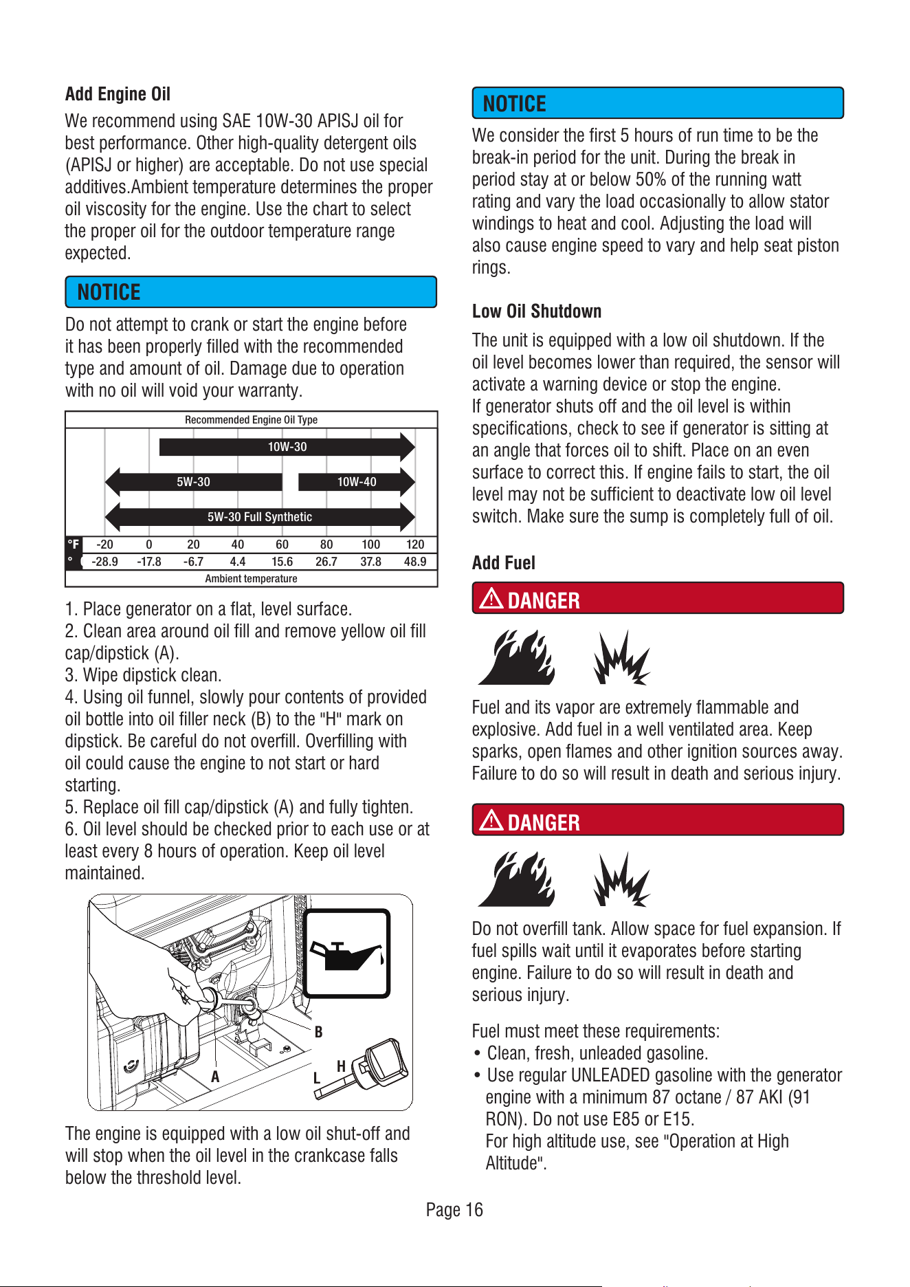
Add Engine Oil
Low Oil Shutdown
The unit is equipped with a low oil shutdown. If the
oil level becomes lower than required, the sensor will
activate a warning device or stop the engine.
If generator shuts off and the oil level is within
specifications, check to see if generator is sitting at
an angle that forces oil to shift. Place on an even
surface to correct this. If engine fails to start, the oil
level may not be sufficient to deactivate low oil level
switch. Make sure the sump is completely full of oil.
Add Fuel
Fuel must meet these requirements:
• Clean, fresh, unleaded gasoline.
• Use regular UNLEADED gasoline with the generator
engine with a minimum 87 octane / 87 AKI (91
RON). Do not use E85 or E15.
For high altitude use, see "Operation at High
Altitude".
The engine is equipped with a low oil shut-off and
will stop when the oil level in the crankcase falls
below the threshold level.
-2 0 0 2 0 4 0 6 0
Ambient temperature
Recommended Engine Oil Type
8 0 1 00 1 2 0
-2 8 .9
°F
° C -1 7 .8 -6 .7 4 .4 1 5 .6 2 6 .7 3 7 .8 4 8 .9
1 0W-3 0
5 W-3 0 Full Synthetic
1 0W-4 05 W-3 0
NOTICE
NOTICE
DANGER
Fuel and its vapor are extremely flammable and
explosive. Add fuel in a well ventilated area. Keep
sparks, open flames and other ignition sources away.
Failure to do so will result in death and serious injury.
DANGER
Do not overfill tank. Allow space for fuel expansion. If
fuel spills wait until it evaporates before starting
engine. Failure to do so will result in death and
serious injury.
1. Place generator on a flat, level surface.
2. Clean area around oil fill and remove yellow oil fill
cap/dipstick (A).
3. Wipe dipstick clean.
4. Using oil funnel, slowly pour contents of provided
oil bottle into oil filler neck (B) to the "H" mark on
dipstick. Be careful do not overfill. Overfilling with
oil could cause the engine to not start or hard
starting.
5. Replace oil fill cap/dipstick (A) and fully tighten.
6. Oil level should be checked prior to each use or at
least every 8 hours of operation. Keep oil level
maintained.
We recommend using SAE 10W-30 APISJ oil for
best performance. Other high-quality detergent oils
(APISJ or higher) are acceptable. Do not use special
additives.Ambient temperature determines the proper
oil viscosity for the engine. Use the chart to select
the proper oil for the outdoor temperature range
expected.
A
B
H
L
• DO NOT mix oil in gasoline.
• DO NOT modify engine to run on alternate fuels.
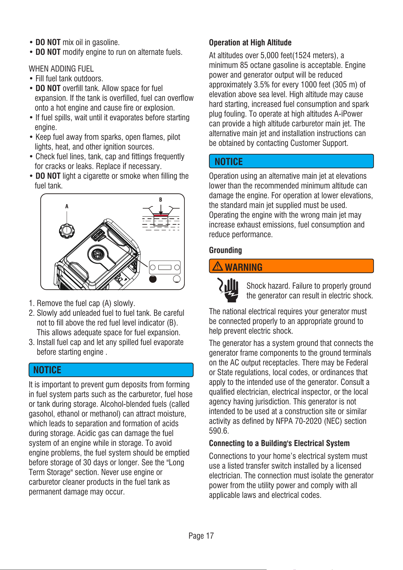
WHEN ADDING FUEL
• Fill fuel tank outdoors.
• DO NOT overfill tank. Allow space for fuel
expansion. If the tank is overfilled, fuel can overflow
onto a hot engine and cause fire or explosion.
• If fuel spills, wait until it evaporates before starting
engine.
• Keep fuel away from sparks, open flames, pilot
lights, heat, and other ignition sources.
• Check fuel lines, tank, cap and fittings frequently
for cracks or leaks. Replace if necessary.
• DO NOT light a cigarette or smoke when filling the
fuel tank.
Operation using an alternative main jet at elevations
lower than the recommended minimum altitude can
damage the engine. For operation at lower elevations,
the standard main jet supplied must be used.
Operating the engine with the wrong main jet may
increase exhaust emissions, fuel consumption and
reduce performance.
It is important to prevent gum deposits from forming
in fuel system parts such as the carburetor, fuel hose
or tank during storage. Alcohol-blended fuels (called
gasohol, ethanol or methanol) can attract moisture,
which leads to separation and formation of acids
during storage. Acidic gas can damage the fuel
system of an engine while in storage. To avoid
engine problems, the fuel system should be emptied
before storage of 30 days or longer. See the "Long
Term Storage" section. Never use engine or
carburetor cleaner products in the fuel tank as
permanent damage may occur.
Operation at High Altitude
At altitudes over 5,000 feet(1524 meters), a
minimum 85 octane gasoline is acceptable. Engine
power and generator output will be reduced
approximately 3.5% for every 1000 feet (305 m) of
elevation above sea level. High altitude may cause
hard starting, increased fuel consumption and spark
plug fouling. To operate at high altitudes A-iPower
can provide a high altitude carburetor main jet. The
alternative main jet and installation instructions can
be obtained by contacting Customer Support.
Grounding
The national electrical requires your generator must
be connected properly to an appropriate ground to
help prevent electric shock.
The generator has a system ground that connects the
generator frame components to the ground terminals
on the AC output receptacles. There may be Federal
or State regulations, local codes, or ordinances that
apply to the intended use of the generator. Consult a
qualified electrician, electrical inspector, or the local
agency having jurisdiction. This generator is not
intended to be used at a construction site or similar
activity as defined by NFPA 70-2020 (NEC) section
590.6.
Connecting to a Building's Electrical System
Connections to your home’s electrical system must
use a listed transfer switch installed by a licensed
electrician. The connection must isolate the generator
power from the utility power and comply with all
applicable laws and electrical codes.
1. Remove the fuel cap (A) slowly.
2. Slowly add unleaded fuel to fuel tank. Be careful
not to fill above the red fuel level indicator (B).
This allows adequate space for fuel expansion.
3. Install fuel cap and let any spilled fuel evaporate
before starting engine .
Page 17
NOTICE
NOTICE
WARNING
Shock hazard. Failure to properly ground
the generator can result in electric shock.
B
A
OPERATION
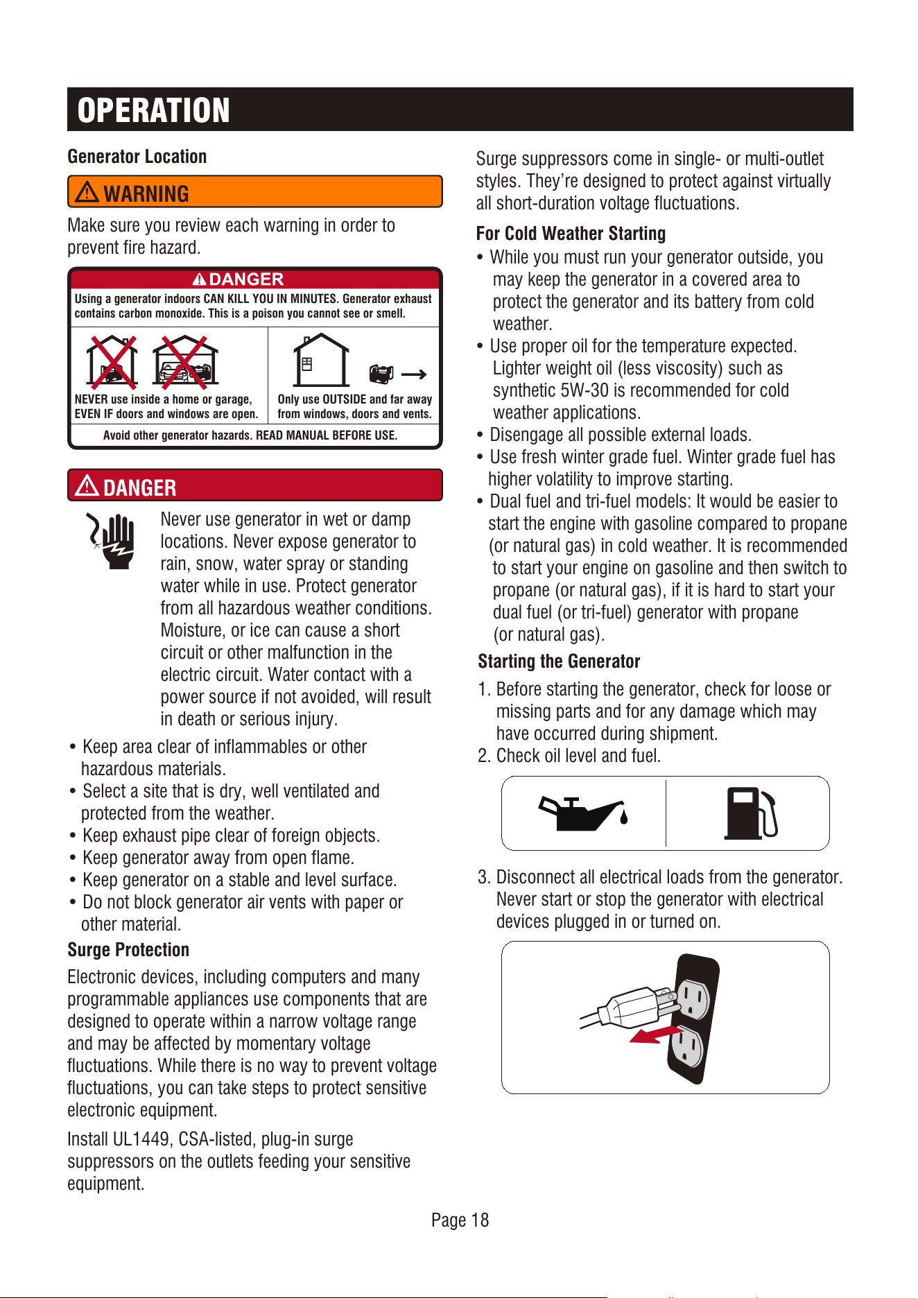
Generator Location
Surge Protection
Starting the Generator
Make sure you review each warning in order to
prevent fire hazard.
• Keep area clear of inflammables or other
hazardous materials.
• Select a site that is dry, well ventilated and
protected from the weather.
• Keep exhaust pipe clear of foreign objects.
• Keep generator away from open flame.
• Keep generator on a stable and level surface.
• Do not block generator air vents with paper or
other material.
Electronic devices, including computers and many
programmable appliances use components that are
designed to operate within a narrow voltage range
and may be affected by momentary voltage
fluctuations. While there is no way to prevent voltage
fluctuations, you can take steps to protect sensitive
electronic equipment.
Install UL1449, CSA-listed, plug-in surge
suppressors on the outlets feeding your sensitive
equipment.
3. Disconnect all electrical loads from the generator.
Never start or stop the generator with electrical
devices plugged in or turned on.
1. Before starting the generator, check for loose or
missing parts and for any damage which may
have occurred during shipment.
2. Check oil level and fuel.
Using a generator indoors CAN KILL YOU IN MINUTES. Generator exhaust
contains carbon monoxide. This is a poison you cannot see or smell.
NEVER use inside a home or garage,
EVEN IF doors and windows are open.
Avoid other generator hazards. READ MANUAL BEFORE USE.
Only use OUTSIDE and far away
from windows, doors and vents.
WARNING
DANGER
Never use generator in wet or damp
locations. Never expose generator to
rain, snow, water spray or standing
water while in use. Protect generator
from all hazardous weather conditions.
Moisture, or ice can cause a short
circuit or other malfunction in the
electric circuit. Water contact with a
power source if not avoided, will result
in death or serious injury.
Page 18
Surge suppressors come in single- or multi-outlet
styles. They’re designed to protect against virtually
all short-duration voltage fluctuations.
For Cold Weather Starting
• While you must run your generator outside, you
may keep the generator in a covered area to
protect the generator and its battery from cold
weather.
• Use proper oil for the temperature expected.
Lighter weight oil (less viscosity) such as
synthetic 5W-30 is recommended for cold
weather applications.
• Disengage all possible external loads.
• Use fresh winter grade fuel. Winter grade fuel has
higher volatility to improve starting.
• Dual fuel and tri-fuel models: It would be easier to
start the engine with gasoline compared to propane
(or natural gas) in cold weather. It is recommended
to start your engine on gasoline and then switch to
propane (or natural gas), if it is hard to start your
dual fuel (or tri-fuel) generator with propane
(or natural gas).
Page 19
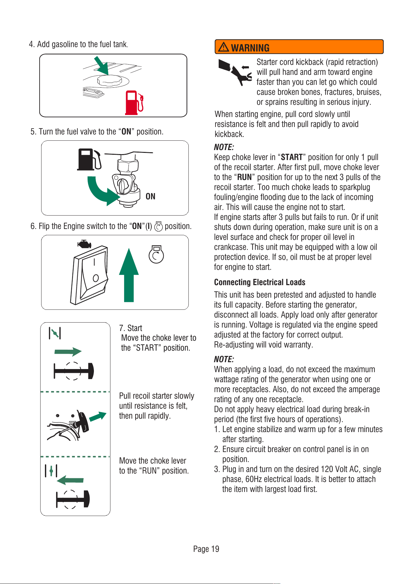
5. Turn the fuel valve to the “ON” position.
6. Flip the Engine switch to the “ON”(l) position.
ON
Connecting Electrical Loads
This unit has been pretested and adjusted to handle
its full capacity. Before starting the generator,
disconnect all loads. Apply load only after generator
is running. Voltage is regulated via the engine speed
adjusted at the factory for correct output.
Re-adjusting will void warranty.
NOTE:
Keep choke lever in “START” position for only 1 pull
of the recoil starter. After first pull, move choke lever
to the “RUN” position for up to the next 3 pulls of the
recoil starter. Too much choke leads to sparkplug
fouling/engine flooding due to the lack of incoming
air. This will cause the engine not to start.
If engine starts after 3 pulls but fails to run. Or if unit
shuts down during operation, make sure unit is on a
level surface and check for proper oil level in
crankcase. This unit may be equipped with a low oil
protection device. If so, oil must be at proper level
for engine to start.
NOTE:
When applying a load, do not exceed the maximum
wattage rating of the generator when using one or
more receptacles. Also, do not exceed the amperage
rating of any one receptacle.
Do not apply heavy electrical load during break-in
period (the first five hours of operations).
1. Let engine stabilize and warm up for a few minutes
after starting.
2. Ensure circuit breaker on control panel is in on
position.
3. Plug in and turn on the desired 120 Volt AC, single
phase, 60Hz electrical loads. It is better to attach
the item with largest load first.
When starting engine, pull cord slowly until
resistance is felt and then pull rapidly to avoid
kickback.
Starter cord kickback (rapid retraction)
will pull hand and arm toward engine
faster than you can let go which could
cause broken bones, fractures, bruises,
or sprains resulting in serious injury.
WARNING
4. Add gasoline to the fuel tank.
7. Start
Move the choke lever to
the “START” position.
Move the choke lever
to the “RUN” position.
Pull recoil starter slowly
until resistance is felt,
then pull rapidly.
Page 20
Stopping the Engine
Low Idle Switch
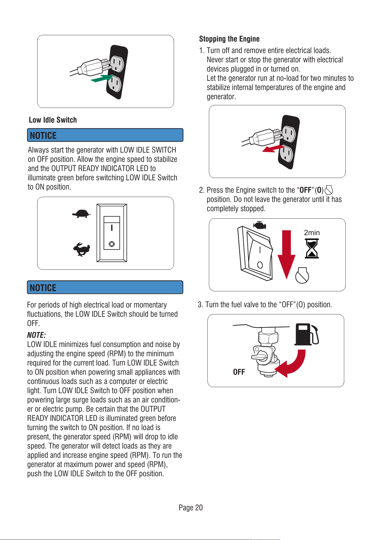
1. Turn off and remove entire electrical loads.
Never start or stop the generator with electrical
devices plugged in or turned on.
Let the generator run at no-load for two minutes to
stabilize internal temperatures of the engine and
generator.
OFF
2. Press the Engine switch to the “OFF”(O)
position. Do not leave the generator until it has
completely stopped.
2min
3. Turn the fuel valve to the “OFF”(O) position.
NOTICE
Always start the generator with LOW IDLE SWITCH
on OFF position. Allow the engine speed to stabilize
and the OUTPUT READY INDICATOR LED to
illuminate green before switching LOW IDLE Switch
to ON position.
NOTE:
LOW IDLE minimizes fuel consumption and noise by
adjusting the engine speed (RPM) to the minimum
required for the current load. Turn LOW IDLE Switch
to ON position when powering small appliances with
continuous loads such as a computer or electric
light. Turn LOW IDLE Switch to OFF position when
powering large surge loads such as an air condition-
er or electric pump. Be certain that the OUTPUT
READY INDICATOR LED is illuminated green before
turning the switch to ON position. If no load is
present, the generator speed (RPM) will drop to idle
speed. The generator will detect loads as they are
applied and increase engine speed (RPM). To run the
generator at maximum power and speed (RPM),
push the LOW IDLE Switch to the OFF position.
NOTICE
For periods of high electrical load or momentary
fluctuations, the LOW IDLE Switch should be turned
OFF.
Page 21
Do Not Overload Generator
Overloading a generator in excess of its rated wattage
capacity can result in damage to the generator and to
connected electrical devices.
To prolong the life of your generator and attached
devices, follow these steps to add electrical load:
1. Start the generator with no electrical load attached.
2. Allow the engine to run for several minutes to
stabilize.
3. Plug in and turn on the first item. It is best to
attach the item with the largest load first.
4. Allow the engine to stabilize.
5. Plug in and turn on the next item.
6. Allow the engine to stabilize.
7. Repeat steps 5-6 for each additional item.
Low Oil Shutdown
If the engine oil drops below a preset level, an oil
switch will stop the engine. Check oil level with
dipstick.
If oil level is between LOW and HIGH mark on
dipstick:
1. DO NOT try to restart the engine.
2. Contact an Authorized Service Dealer.
3. DO NOT operate engine until oil level is corrected.
If oil level is below LOW mark on dipstick:
1. Add oil to bring level to HIGH mark.
2. Restart engine and if the engine stops again a low
oil condition may still exist. DO NOT try to restart
the engine.
3. Contact Customer Service.
4. DO NOT operate engine until oil level is corrected.
NOTE:
Always ensure that the fuel valve is in the “OFF”
position when the engine is not in use.
If the engine will not be used for a period of two
weeks or longer, please see the Storage section for
proper engine and fuel storage.
Fuel and its vapors are extremely flammable and
explosive which could cause burns, fire or explosion
resulting in death or serious injury.
DO NOT stop engine by moving choke control to
“START” position.
WARNING
Parallel Operation (2 x SUA4600iF Models)
Paralleling this generator to a generator that is not
compatible can cause a low voltage output that can
damage tools and appliances powered by the
generator. Do not connect or disconnect parallel
cables while the generator is running to avoid damage.
Parallel operation gives you the ability to link this
generator to a compatible AIPOWER generator for
combined running and starting power output. Use
NOTICE
WARNING
Fire and electrocution hazard. Never connect or
disconnect the parallel cord leads when a generator
is running. Do not parallel more than two generators.
Use only AIPOWER generators for paralleling.
NOTE:
Only connect two identical (same model) generators
together for parallel operation.
only the AIPOWER approved cables for parallel
operation. For single generator operation, the parallel
operation cable must be removed.
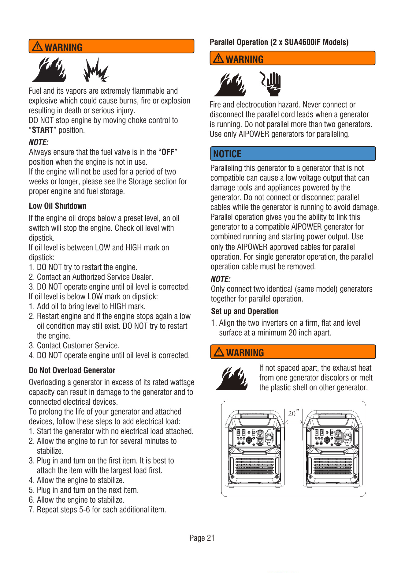
1. Align the two inverters on a firm, flat and level
surface at a minimum 20 inch apart.
Set up and Operation
WARNING
If not spaced apart, the exhaust heat
from one generator discolors or melt
the plastic shell on other generator.
20”
Page 22
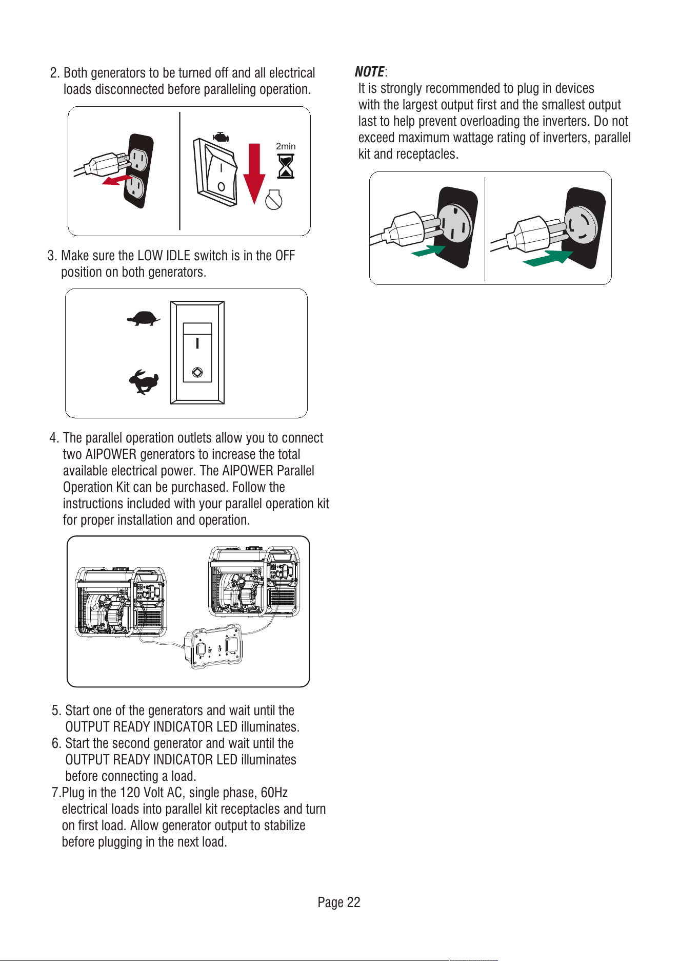
2. Both generators to be turned off and all electrical
loads disconnected before paralleling operation.
4. The parallel operation outlets allow you to connect
two AIPOWER generators to increase the total
available electrical power. The AIPOWER Parallel
Operation Kit can be purchased. Follow the
instructions included with your parallel operation kit
for proper installation and operation.
5. Start one of the generators and wait until the
OUTPUT READY INDICATOR LED illuminates.
6. Start the second generator and wait until the
OUTPUT READY INDICATOR LED illuminates
before connecting a load.
7.Plug in the 120 Volt AC, single phase, 60Hz
electrical loads into parallel kit receptacles and turn
on first load. Allow generator output to stabilize
before plugging in the next load.
3. Make sure the LOW IDLE switch is in the OFF
position on both generators.
NOTE:
It is strongly recommended to plug in devices
with the largest output first and the smallest output
last to help prevent overloading the inverters. Do not
exceed maximum wattage rating of inverters, parallel
kit and receptacles.
2min

MAINTENANCE AND STORAGE
MAINTENANCE SCHEDULE
Regular Maintenance will improve the performance
and extend the life of your generator. Follow
maintenance schedule intervals whichever occurs
first according to use.
Walk-Around Inspection
Before starting the engine perform a visual inspection
of the unit. Look for:
• Proper engine oil level
• Proper fuel level
• Fluid leaks
• Loose clamps and bolts
• Cracked fuel line
• Loose or frayed wiring
• Built up debris
NOTE: Adverse conditions will require more frequent
services.
General Recommendations
NOTE:
Maintenance should be performed more frequently
when generator is used in dusty areas.
When generator has exceeded the maximum figures
specified in the table, maintenance should still be
cycled according tothe intervals of time or hours
stated herein.
NOTE:
Change oil every month when operating under heavy
load or high temperatures. Clean the air filter more
often under dirty or dusty operating conditions.
Replace air filter if they cannot be adequately cleaned.
Regular maintenance will improve the performance
and extend the life of the generator. See any
authorized dealer for service.
The generator's warranty does not cover items that
have been subjected to operator abuse or negligence.
To receive full value from the warranty, the operator
must maintain generator as instructed in this manual.
Some adjustments will need to be made periodically
to properly maintain your generator. All service and
adjustments should be made at least once each
season. Follow the requirements in the Maintenanc
Shedule chart above.
ENGINE MAINTENANCE
CAUTION
To prevent accidental starting, remove and ground
spark plug wire before performing any service.
Engine Oil Level Check
Avoid skin contact with engine oil. Wear protective
clothing and equipment. Wash all exposed skin with
soap and water.
Before Each Use
* To be performed by authorized service center
Check engine oil level
Walk-around inspection
First 5 Hours (Break-In)
Change engine oil
First 25 Hours or First Month
Change engine oil
Every 100 Hours or 6 Months
Change engine oil
Clean Air Filter
Inspect/Adjust/Replace Spark plug
Inspect/Clean/Replace Spark Arrester
Every 200 Hours or 12 Months
Replace Air filter
Replace Spark Plug
Inspect/Adjust Valve Clearance*
Always use the specified engine oil. Failure to use the
specified engine oil can cause accelerated wear
and/or shorten the life of the engine.
When using the generator under extreme, dirty, dusty
conditions or in extremely hot weather, change the
oil more frequently.
Ambient air temperature will affect engine oil
performance. Change the type of engine oil used
based on weather conditions.
NOTICE
Page 23
Page 24
-2 0 0 2 0 4 0 6 0
A mbient tem perature
Recomm end ed Engine O il Type
8 0 1 00 1 2 0
-2 8 .9
°F
°C -1 7 .8 -6 .7 4 .4 1 5 .6 2 6 .7 3 7 .8 4 8 .9
1 0W -3 0
5 W-3 0 Full Synt hetic
1 0W -4 05 W -3 0
CAUTION
Avoid prolonged or repeated skin contact with used
motor oil.
Change Engine Oil
Change engine oil per maintenance schedule.
If you are using your generator under extremely dirty
or dusty conditions, or in extremely hot weather,
change the oil more often.
Risk of burns. Allow engine to cool
before draining oil or coolant. Failure to
do so could result in death of serious
injury.
WARNING
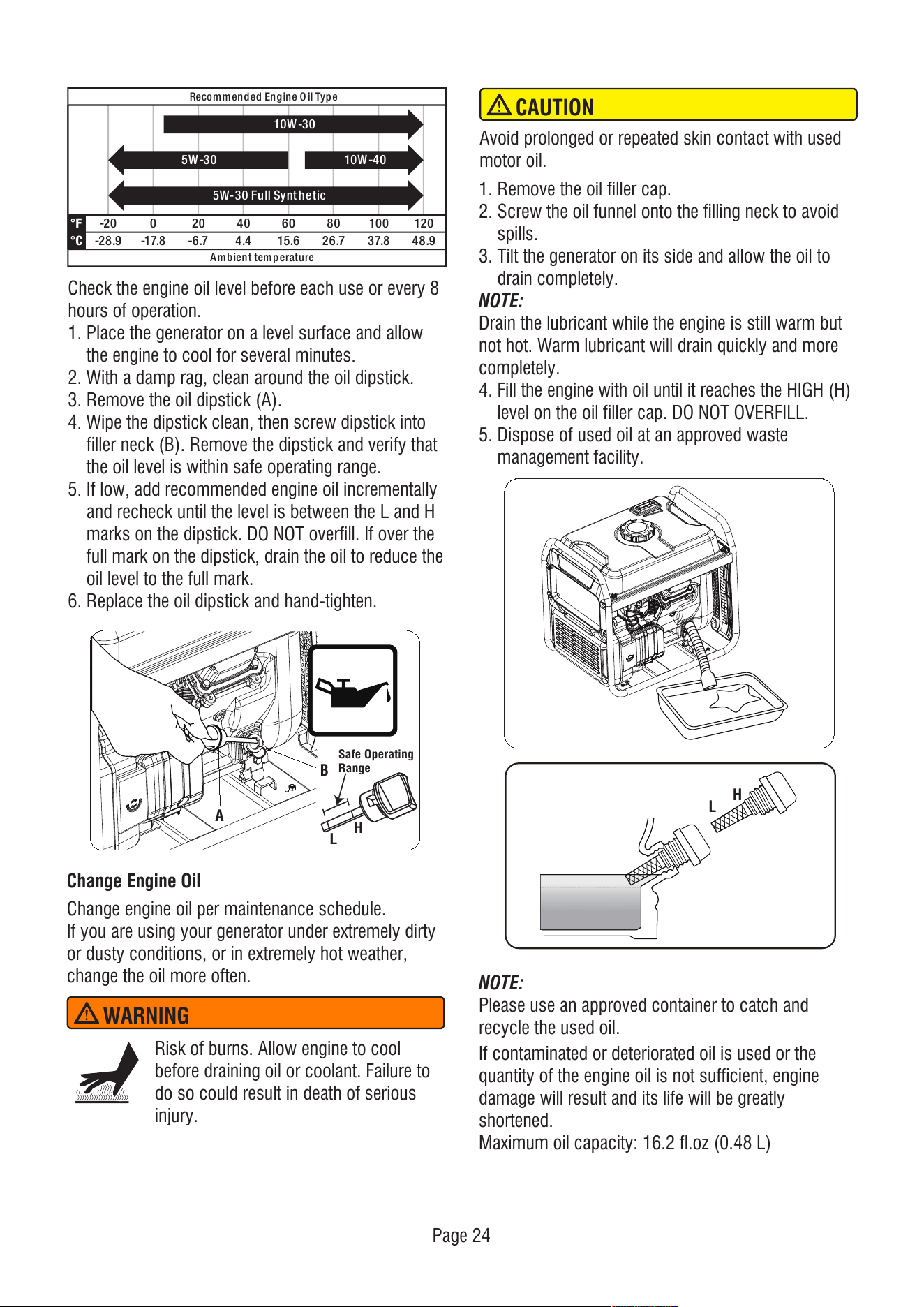
Check the engine oil level before each use or every 8
hours of operation.
1. Place the generator on a level surface and allow
the engine to cool for several minutes.
2. With a damp rag, clean around the oil dipstick.
3. Remove the oil dipstick (A).
4. Wipe the dipstick clean, then screw dipstick into
filler neck (B). Remove the dipstick and verify that
the oil level is within safe operating range.
5. If low, add recommended engine oil incrementally
and recheck until the level is between the L and H
marks on the dipstick. DO NOT overfill. If over the
full mark on the dipstick, drain the oil to reduce the
oil level to the full mark.
6. Replace the oil dipstick and hand-tighten.
H
Safe Operating
Range
L
A
B
1. Remove the oil filler cap.
2. Screw the oil funnel onto the filling neck to avoid
spills.
3. Tilt the generator on its side and allow the oil to
drain completely.
NOTE:
Drain the lubricant while the engine is still warm but
not hot. Warm lubricant will drain quickly and more
completely.
4. Fill the engine with oil until it reaches the HIGH (H)
level on the oil filler cap. DO NOT OVERFILL.
5. Dispose of used oil at an approved waste
management facility.
H
L
NOTE:
Please use an approved container to catch and
recycle the used oil.
If contaminated or deteriorated oil is used or the
quantity of the engine oil is not sufficient, engine
damage will result and its life will be greatly
shortened.
Maximum oil capacity: 16.2 fl.oz (0.48 L)
Page 25
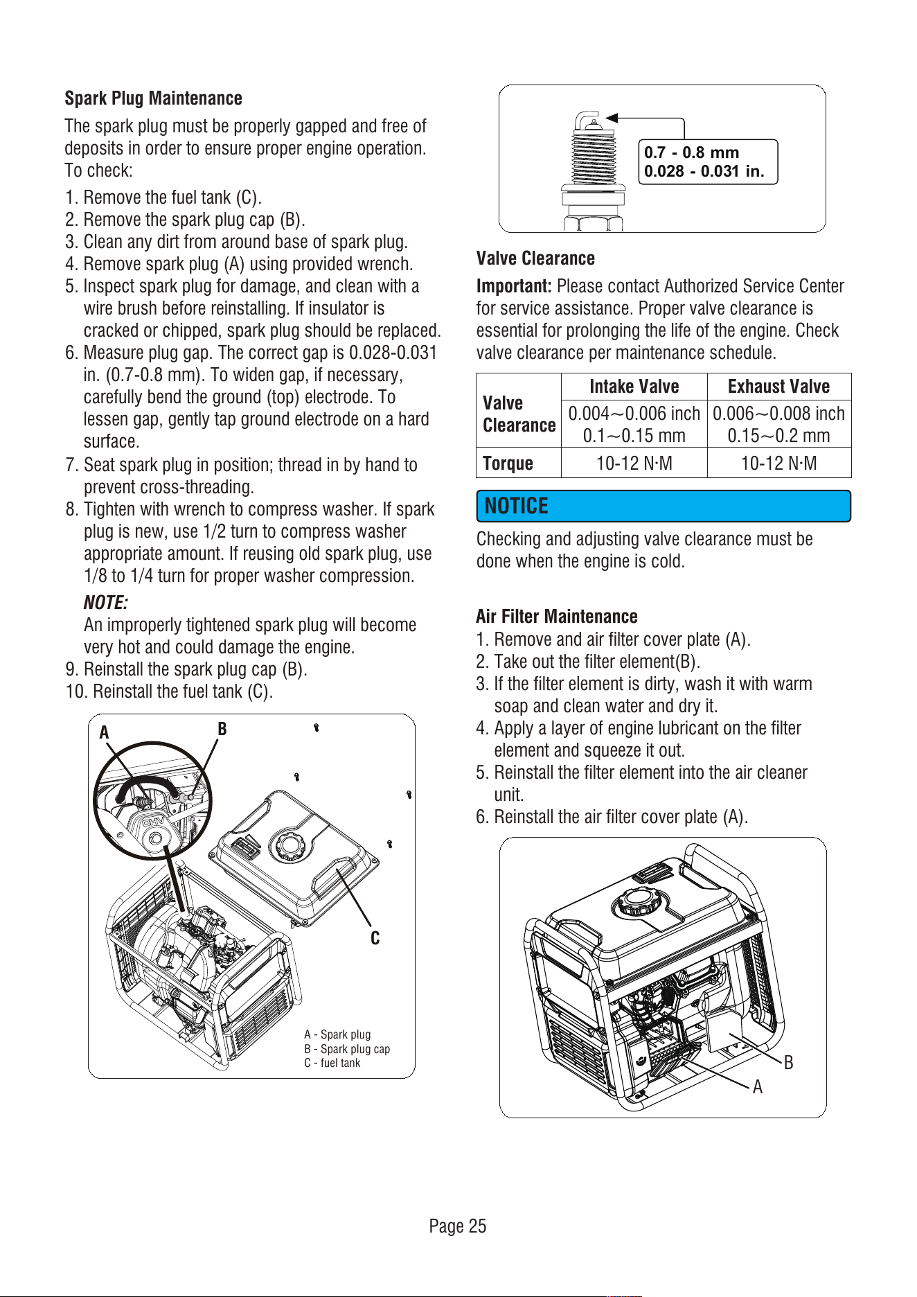
Spark Plug Maintenance
The spark plug must be properly gapped and free of
deposits in order to ensure proper engine operation.
To check:
1. Remove the fuel tank (C).
2. Remove the spark plug cap (B).
3. Clean any dirt from around base of spark plug.
4. Remove spark plug (A) using provided wrench.
5. Inspect spark plug for damage, and clean with a
wire brush before reinstalling. If insulator is
cracked or chipped, spark plug should be replaced.
6. Measure plug gap. The correct gap is 0.028-0.031
in. (0.7-0.8 mm). To widen gap, if necessary,
carefully bend the ground (top) electrode. To
lessen gap, gently tap ground electrode on a hard
surface.
7. Seat spark plug in position; thread in by hand to
prevent cross-threading.
8. Tighten with wrench to compress washer. If spark
plug is new, use 1/2 turn to compress washer
appropriate amount. If reusing old spark plug, use
1/8 to 1/4 turn for proper washer compression.
NOTE:
An improperly tightened spark plug will become
very hot and could damage the engine.
9. Reinstall the spark plug cap (B).
10. Reinstall the fuel tank (C).
Air Filter Maintenance
1. Remove and air filter cover plate (A).
2. Take out the filter element(B).
3. If the filter element is dirty, wash it with warm
soap and clean water and dry it.
4. Apply a layer of engine lubricant on the filter
element and squeeze it out.
5. Reinstall the filter element into the air cleaner
unit.
6. Reinstall the air filter cover plate (A).
B
A
Checking and adjusting valve clearance must be
done when the engine is cold.
NOTICE
0.004~0.006 inch
0.1~0.15 mm
0.006~0.008 inch
0.15~0.2 mm
10-12 N·M 10-12 N·M
Intake Valve Exhaust Valve
Valve Clearance
Valve
Clearance
Torque
Please contact Authorized Service Center
for service assistance. Proper valve clearance is
essential for prolonging the life of the engine. Check
valve clearance per maintenance schedule.
Important:
0.7 - 0.8 mm
0.028 - 0.031 in.
A
B
A - Spark plug
B - Spark plug cap
C - fuel tank
C
Page 26
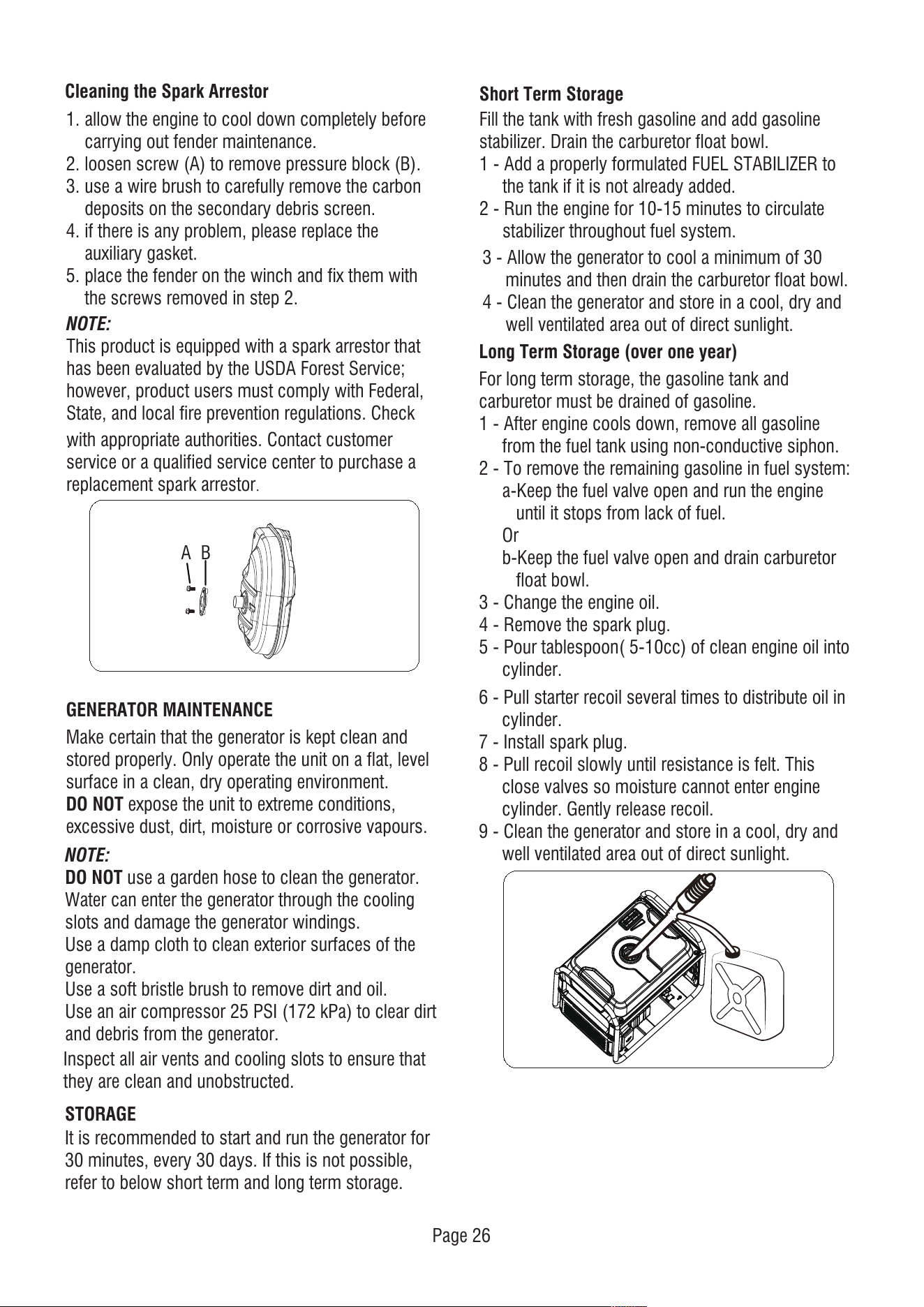
Long Term Storage (over one year)
6 - Pull starter recoil several times to distribute oil in
cylinder.
7 - Install spark plug.
8 - Pull recoil slowly until resistance is felt. This
close valves so moisture cannot enter engine
cylinder. Gently release recoil.
9 - Clean the generator and store in a cool, dry and
well ventilated area out of direct sunlight.
Short Term Storage
Fill the tank with fresh gasoline and add gasoline
stabilizer. Drain the carburetor float bowl.
1 - Add a properly formulated FUEL STABILIZER to
the tank if it is not already added.
2 - Run the engine for 10-15 minutes to circulate
stabilizer throughout fuel system.
3 - Allow the generator to cool a minimum of 30
minutes and then drain the carburetor float bowl.
4 - Clean the generator and store in a cool, dry and
well ventilated area out of direct sunlight.
Cleaning the Spark Arrestor
NOTE:
This product is equipped with a spark arrestor that
has been evaluated by the USDA Forest Service;
however, product users must comply with Federal,
State, and local fire prevention regulations. Check
.
with appropriate authorities. Contact customer
service or a qualified service center to purchase a
replacement spark arrestor.
STORAGE
It is recommended to start and run the generator for
30 minutes, every 30 days. If this is not possible,
refer to below short term and long term storage.
GENERATOR MAINTENANCE
Make certain that the generator is kept clean and
stored properly. Only operate the unit on a flat, level
surface in a clean, dry operating environment.
DO NOT expose the unit to extreme conditions,
excessive dust, dirt, moisture or corrosive vapours.
NOTE:
DO NOT use a garden hose to clean the generator.
Water can enter the generator through the cooling
slots and damage the generator windings.
Use a damp cloth to clean exterior surfaces of the
generator.
Use a soft bristle brush to remove dirt and oil.
Use an air compressor 25 PSI (172 kPa) to clear dirt
and debris from the generator.
Inspect all air vents and cooling slots to ensure that
they are clean and unobstructed.
For long term storage, the gasoline tank and
carburetor must be drained of gasoline.
1 - After engine cools down, remove all gasoline
from the fuel tank using non-conductive siphon.
2 - To remove the remaining gasoline in fuel system:
a-Keep the fuel valve open and run the engine
until it stops from lack of fuel.
Or
b-Keep the fuel valve open and drain carburetor
float bowl.
3 - Change the engine oil.
4 - Remove the spark plug.
5 - Pour tablespoon( 5-10cc) of clean engine oil into
cylinder.
A
B
1. allow the engine to cool down completely before
carrying out fender maintenance.
2. loosen screw (A) to remove pressure block (B).
3. use a wire brush to carefully remove the carbon
deposits on the secondary debris screen.
4. if there is any problem, please replace the
auxiliary gasket.
5. place the fender on the winch and fix them with
the screws removed in step 2.
Page 27
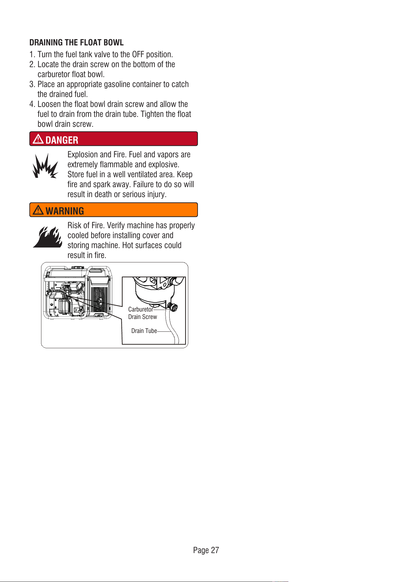
DRAINING THE FLOAT BOWL
1. Turn the fuel tank valve to the OFF position.
2. Locate the drain screw on the bottom of the
carburetor float bowl.
3. Place an appropriate gasoline container to catch
the drained fuel.
4. Loosen the float bowl drain screw and allow the
fuel to drain from the drain tube. Tighten the float
bowl drain screw.
DANGER
Explosion and Fire. Fuel and vapors are
extremely flammable and explosive.
Store fuel in a well ventilated area. Keep
fire and spark away. Failure to do so will
result in death or serious injury.
WARNING
Risk of Fire. Verify machine has properly
cooled before installing cover and
storing machine. Hot surfaces could
result in fire.
Carburetor
Drain Screw
Drain Tube
Page 28
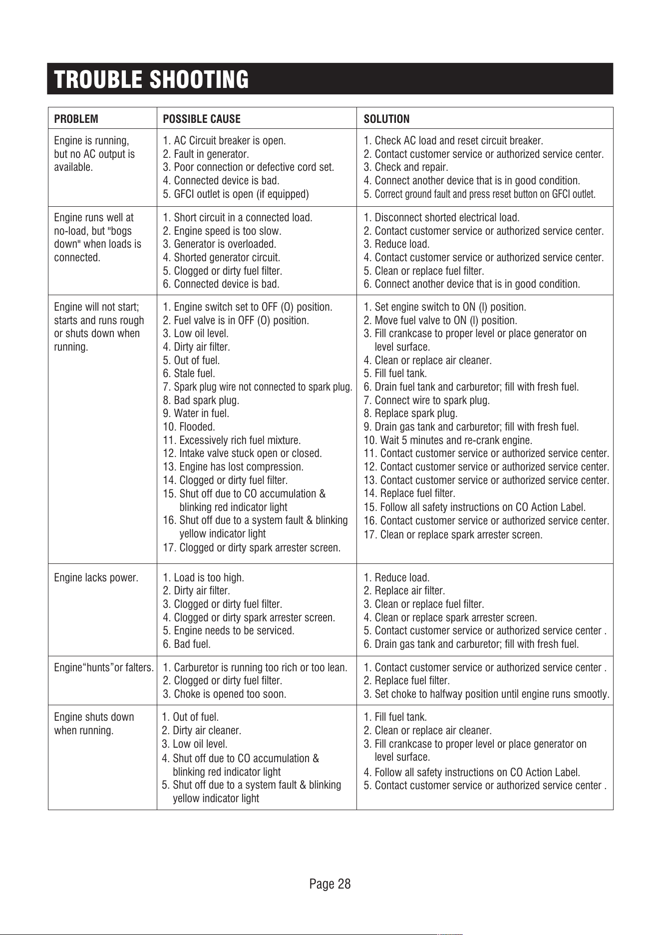
PROBLEM
Engine is running,
but no AC output is
available.
1. AC Circuit breaker is open.
2. Fault in generator.
3. Poor connection or defective cord set.
4. Connected device is bad.
5. GFCI outlet is open (if equipped)
1. Check AC load and reset circuit breaker.
2. Contact customer service or authorized service center.
3. Check and repair.
4. Connect another device that is in good condition.
5.
Correct ground fault and press reset button on GFCI outlet.
Engine runs well at
no-load, but "bogs
down" when loads is
connected.
1. Short circuit in a connected load.
2. Engine speed is too slow.
3. Generator is overloaded.
4. Shorted generator circuit.
5. Clogged or dirty fuel filter.
6. Connected device is bad.
1. Disconnect shorted electrical load.
2. Contact customer service or authorized service center.
3. Reduce load.
4. Contact customer service or authorized service center.
5. Clean or replace fuel filter.
6. Connect another device that is in good condition.
Engine will not start;
starts and runs rough
or shuts down when
running.
1. Engine switch set to OFF (O) position.
2. Fuel valve is in OFF (O) position.
3. Low oil level.
4. Dirty air filter.
5. Out of fuel.
6. Stale fuel.
7.
Spark plug wire not connected to spark plug.
8. Bad spark plug.
9. Water in fuel.
10. Flooded.
11. Excessively rich fuel mixture.
12. Intake valve stuck open or closed.
13. Engine has lost compression.
14. Clogged or dirty fuel filter.
1. Set engine switch to ON (l) position.
2. Move fuel valve to ON (l) position.
3. Fill crankcase to proper level or place generator on
level surface.
4. Clean or replace air cleaner.
5. Fill fuel tank.
6. Drain fuel tank and carburetor; fill with fresh fuel.
7. Connect wire to spark plug.
8. Replace spark plug.
9. Drain gas tank and carburetor; fill with fresh fuel.
10. Wait 5 minutes and re-crank engine.
11. Contact customer service or authorized service center.
12. Contact customer service or authorized service center.
13. Contact customer service or authorized service center.
14. Replace fuel filter.
Engine lacks power. 1. Load is too high.
2. Dirty air filter.
3. Clogged or dirty fuel filter.
4. Clogged or dirty spark arrester screen.
5. Engine needs to be serviced.
6. Bad fuel.
17. Clogged or dirty spark arrester screen.
17. Clean or replace spark arrester screen.
1. Reduce load.
2. Replace air filter.
3. Clean or replace fuel filter.
4. Clean or replace spark arrester screen.
5. Contact customer service or authorized service center .
6. Drain gas tank and carburetor; fill with fresh fuel.
Engine“hunts”or falters. 1. Carburetor is running too rich or too lean.
2. Clogged or dirty fuel filter.
3. Choke is opened too soon.
1. Contact customer service or authorized service center .
2. Replace fuel filter.
3. Set choke to halfway position until engine runs smootly.
Engine shuts down
when running.
1. Out of fuel.
2. Dirty air cleaner.
3. Low oil level.
1. Fill fuel tank.
2. Clean or replace air cleaner.
3. Fill crankcase to proper level or place generator on
level surface.
POSSIBLE CAUSE SOLUTION
TROUBLE SHOOTING
4. Shut off due to CO accumulation &
blinking red indicator light
5. Shut off due to a system fault & blinking
yellow indicator light
4. Follow all safety instructions on CO Action Label.
5. Contact customer service or authorized service center .
15. Shut off due to CO accumulation &
blinking red indicator light
16. Shut off due to a system fault & blinking
yellow indicator light
15. Follow all safety instructions on CO Action Label.
16. Contact customer service or authorized service center.
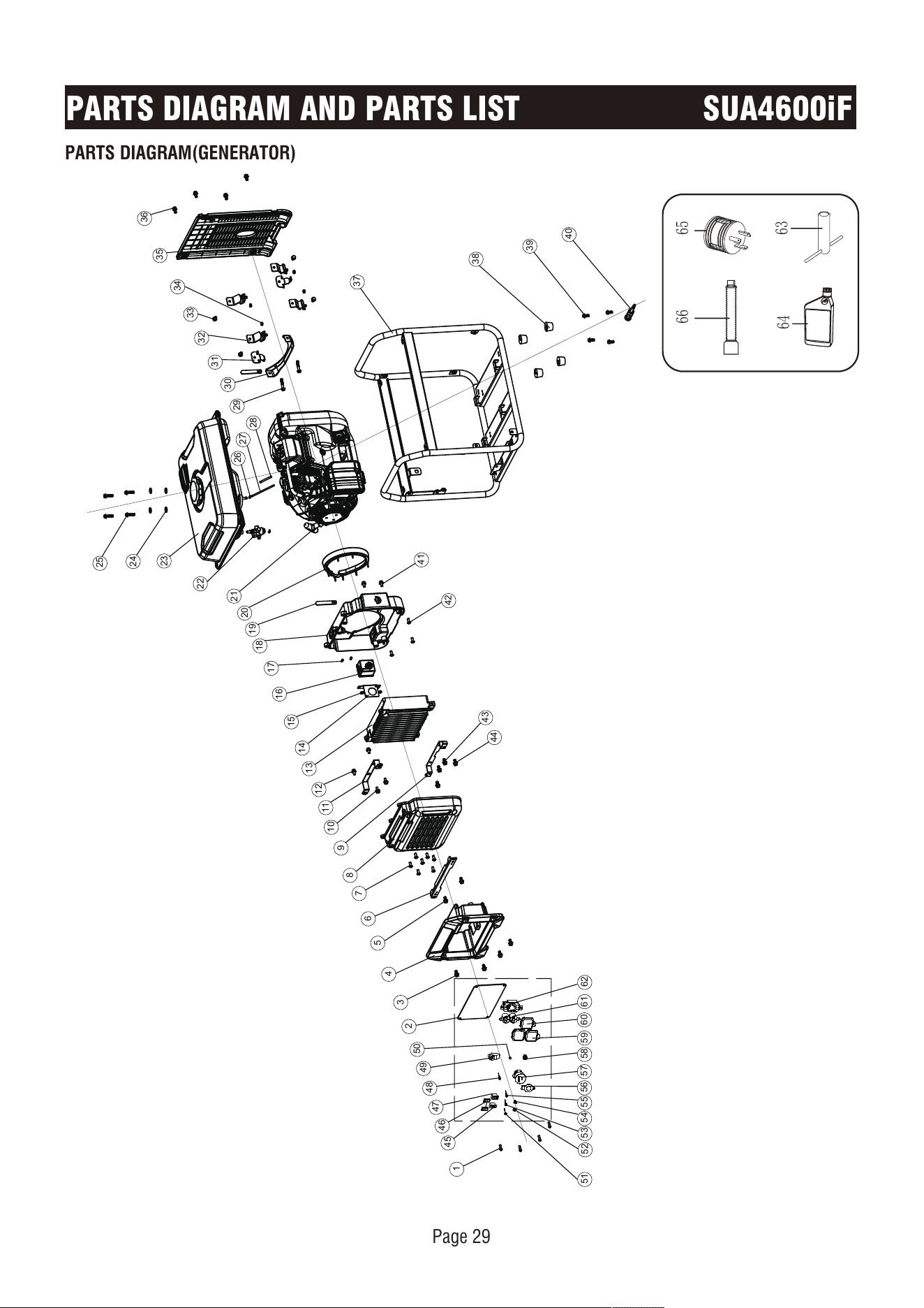
PARTS DIAGRAM(GENERATOR)
PARTS DIAGRAM AND PARTS LIST SUA4600iF
Page 29
1
2
3
4
5
6
7
8
9
11
13
14
15
16
17
18
19
20
23
24
25
31
32
33
35
37
38
39
40
36
21
22
29
30
10
12
34
41
42
44
26
27
28
45
62
46
47
48
49
50
51
52
53
54
55
56 57
58
59
60
61
43
6566
64
63
Page 30
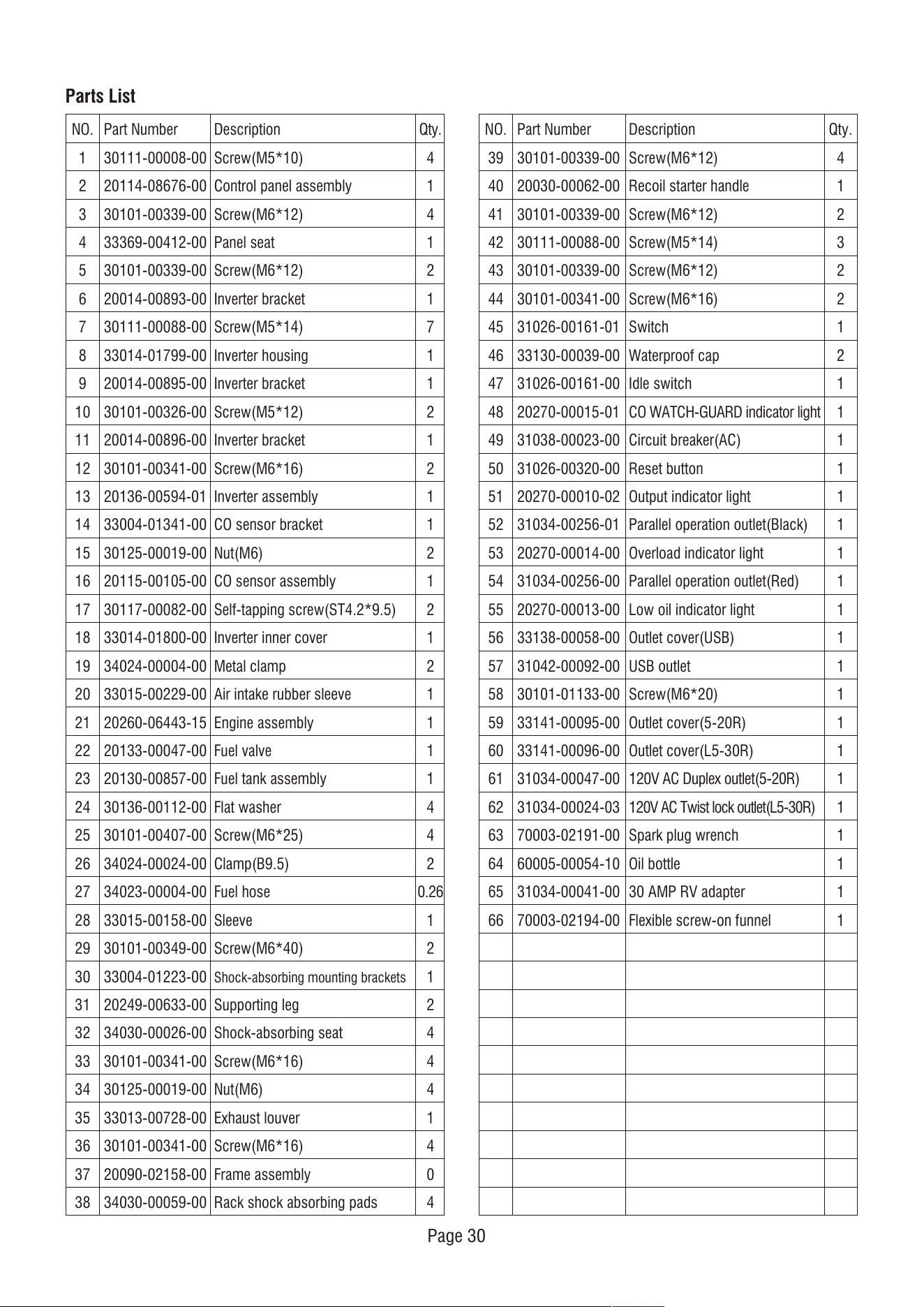
Parts List
NO.
1
2
3
4
5
6
7
8
9
10
11
12
13
14
15
16
17
18
19
20
21
22
23
24
25
26
27
28
29
30
31
32
33
34
35
36
37
38
Qty.
4
1
4
1
2
1
7
1
1
2
1
2
1
1
2
1
2
1
2
1
1
1
1
4
4
2
0.26
1
2
1
2
4
4
4
1
4
0
4
Part Number
30111-00008-00
20114-08676-00
30101-00339-00
33369-00412-00
30101-00339-00
20014-00893-00
30111-00088-00
33014-01799-00
20014-00895-00
30101-00326-00
20014-00896-00
30101-00341-00
20136-00594-01
33004-01341-00
30125-00019-00
20115-00105-00
30117-00082-00
33014-01800-00
34024-00004-00
33015-00229-00
20260-06443-15
20133-00047-00
20130-00857-00
30136-00112-00
30101-00407-00
34024-00024-00
34023-00004-00
33015-00158-00
30101-00349-00
33004-01223-00
20249-00633-00
34030-00026-00
30101-00341-00
30125-00019-00
33013-00728-00
30101-00341-00
20090-02158-00
34030-00059-00
Description
Screw(M5*10)
Control panel assembly
Screw(M6*12)
Panel seat
Screw(M6*12)
Inverter bracket
Screw(M5*14)
Inverter housing
Inverter bracket
Screw(M5*12)
Inverter bracket
Screw(M6*16)
Inverter assembly
CO sensor bracket
Nut(M6)
CO sensor assembly
Self-tapping screw(ST4.2*9.5)
Inverter inner cover
Metal clamp
Air intake rubber sleeve
Engine assembly
Fuel valve
Fuel tank assembly
Flat washer
Screw(M6*25)
Clamp(B9.5)
Fuel hose
Sleeve
Screw(M6*40)
Shock-absorbing mounting brackets
Supporting leg
Shock-absorbing seat
Screw(M6*16)
Nut(M6)
Exhaust louver
Screw(M6*16)
Frame assembly
Rack shock absorbing pads
NO.
39
40
41
42
43
44
45
46
47
48
49
50
51
52
53
54
55
56
57
58
59
60
61
62
63
64
65
66
Qty.
4
1
2
3
2
2
1
2
1
1
1
1
1
1
1
1
1
1
1
1
1
1
1
1
1
1
1
1
Part Number
30101-00339-00
20030-00062-00
30101-00339-00
30111-00088-00
30101-00339-00
30101-00341-00
31026-00161-01
33130-00039-00
31026-00161-00
20270-00015-01
31038-00023-00
31026-00320-00
20270-00010-02
31034-00256-01
20270-00014-00
31034-00256-00
20270-00013-00
33138-00058-00
31042-00092-00
30101-01133-00
33141-00095-00
33141-00096-00
31034-00047-00
31034-00024-03
70003-02191-00
60005-00054-10
31034-00041-00
70003-02194-00
Description
Screw(M6*12)
Recoil starter handle
Screw(M6*12)
Screw(M5*14)
Screw(M6*12)
Screw(M6*16)
Switch
Waterproof cap
Idle switch
CO WATCH-GUARD indicator light
Circuit breaker(AC)
Reset button
Output indicator light
Parallel operation outlet(Black)
Overload indicator light
Parallel operation outlet(Red)
Low oil indicator light
Outlet cover(USB)
USB outlet
Screw(M6*20)
Outlet cover(5-20R)
Outlet cover(L5-30R)
120V AC Duplex outlet(5-20R)
120V AC Twist lock outlet(L5-30R)
Spark plug wrench
Oil bottle
30 AMP RV adapter
Flexible screw-on funnel
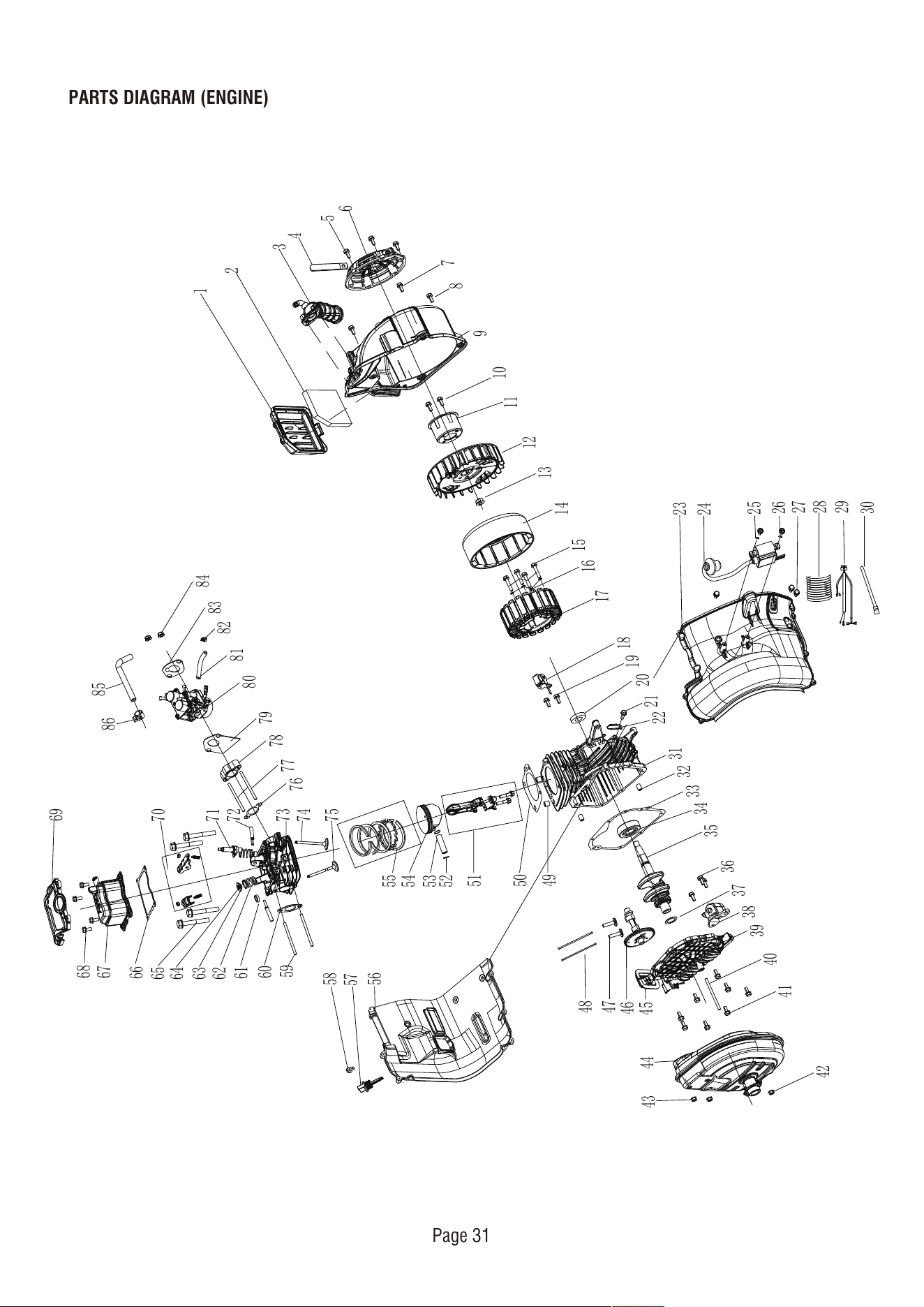
PARTS DIAGRAM (ENGINE)
Page 31
1
2
3
4
5
6
7
8
10
11
12
13
14
15
16
17
18
19
20
21
22
23
24
25
26
27
28
29
30
31
32
33
34
35
36
37
38
39
40
41
42
43
44
45
46
47
48
49
50
51
52
53
54
55
56
57
59
58
60
61
62
63
64
65
66
67
68
69
70
71
72
73
74
75
76
77
78
79
80
81
82
83
84
85
86
9
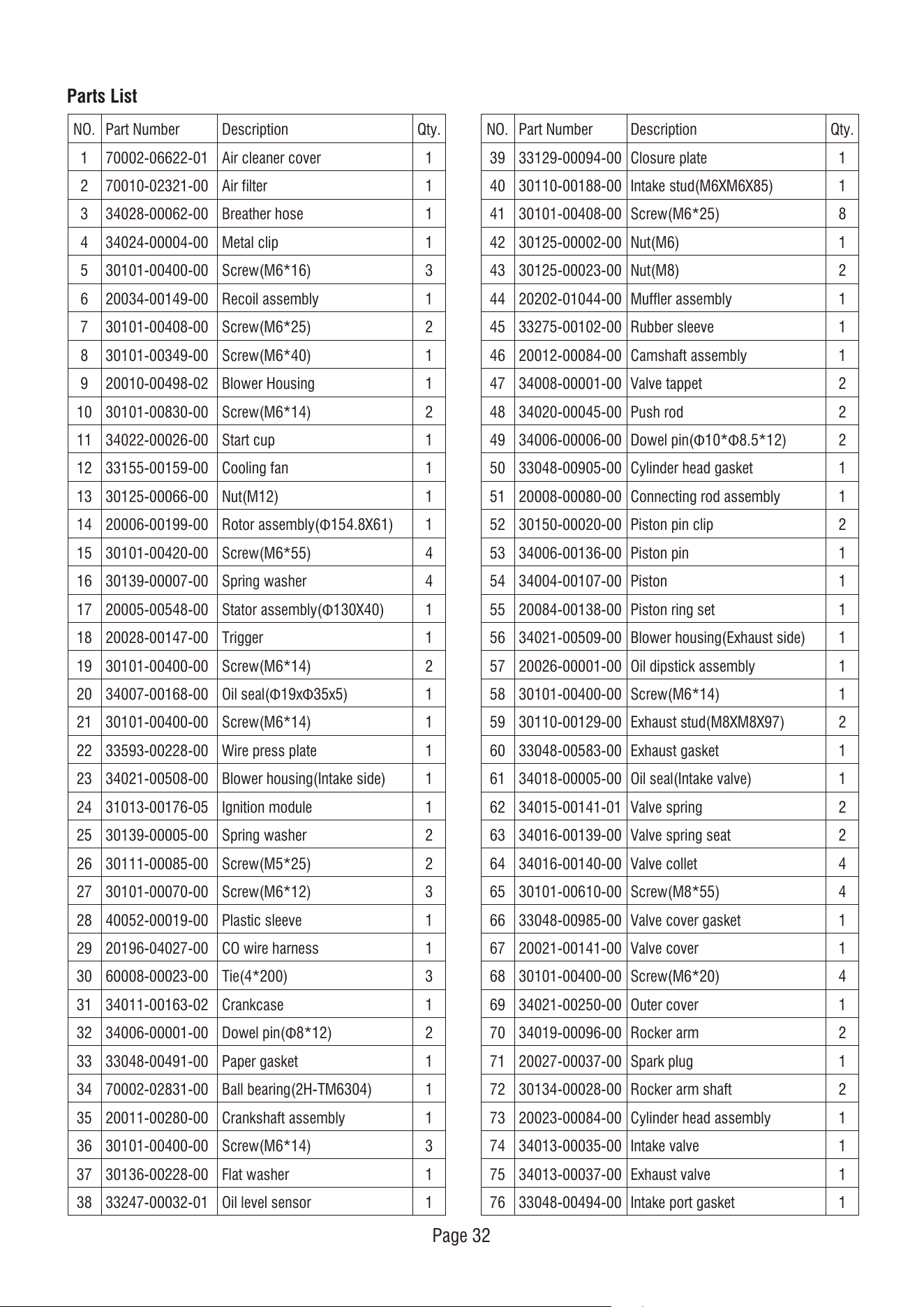
Parts List
NO.
1
2
3
4
5
6
7
8
9
10
11
12
13
14
15
16
17
18
19
20
21
22
23
24
25
26
27
28
29
30
31
32
33
34
35
36
37
38
Qty.
1
1
1
1
3
1
2
1
1
2
1
1
1
1
4
4
1
1
2
1
1
1
1
1
2
2
3
1
1
3
1
2
1
1
1
3
1
1
Part Number
70002-06622-01
70010-02321-00
34028-00062-00
34024-00004-00
30101-00400-00
20034-00149-00
30101-00408-00
30101-00349-00
20010-00498-02
30101-00830-00
34022-00026-00
33155-00159-00
30125-00066-00
20006-00199-00
30101-00420-00
30139-00007-00
20005-00548-00
20028-00147-00
30101-00400-00
34007-00168-00
30101-00400-00
33593-00228-00
34021-00508-00
31013-00176-05
30139-00005-00
30111-00085-00
30101-00070-00
40052-00019-00
20196-04027-00
60008-00023-00
34011-00163-02
34006-00001-00
33048-00491-00
70002-02831-00
20011-00280-00
30101-00400-00
30136-00228-00
33247-00032-01
Description
Air cleaner cover
Air filter
Breather hose
Metal clip
Screw(M6*16)
Recoil assembly
Screw(M6*25)
Screw(M6*40)
Blower Housing
Screw(M6*14)
Start cup
Cooling fan
Nut(M12)
Rotor assembly(Φ154.8X61)
Screw(M6*55)
Spring washer
Stator assembly(Φ130X40)
Trigger
Screw(M6*14)
Oil seal(Φ19xΦ35x5)
Screw(M6*14)
Wire press plate
Blower housing(Intake side)
Ignition module
Spring washer
Screw(M5*25)
Screw(M6*12)
Plastic sleeve
CO wire harness
Tie(4*200)
Crankcase
Dowel pin(Φ8*12)
Paper gasket
Ball bearing(2H-TM6304)
Crankshaft assembly
Screw(M6*14)
Flat washer
Oil level sensor
NO.
39
40
41
42
43
44
45
46
47
48
49
50
51
52
53
54
55
56
57
58
59
60
61
62
63
64
65
66
67
68
69
70
71
72
73
74
75
76
Qty.
1
1
8
1
2
1
1
1
2
2
2
1
1
2
1
1
1
1
1
1
2
1
1
2
2
4
4
1
1
4
1
2
1
2
1
1
1
1
Part Number
33129-00094-00
30110-00188-00
30101-00408-00
30125-00002-00
30125-00023-00
20202-01044-00
33275-00102-00
20012-00084-00
34008-00001-00
34020-00045-00
34006-00006-00
33048-00905-00
20008-00080-00
30150-00020-00
34006-00136-00
34004-00107-00
20084-00138-00
34021-00509-00
20026-00001-00
30101-00400-00
30110-00129-00
33048-00583-00
34018-00005-00
34015-00141-01
34016-00139-00
34016-00140-00
30101-00610-00
33048-00985-00
20021-00141-00
30101-00400-00
34021-00250-00
34019-00096-00
20027-00037-00
30134-00028-00
20023-00084-00
34013-00035-00
34013-00037-00
33048-00494-00
Description
Closure plate
Intake stud(M6XM6X85)
Screw(M6*25)
Nut(M6)
Nut(M8)
Muffler assembly
Rubber sleeve
Camshaft assembly
Valve tappet
Push rod
Dowel pin(Φ10*Φ8.5*12)
Cylinder head gasket
Connecting rod assembly
Piston pin clip
Piston pin
Piston
Piston ring set
Blower housing(Exhaust side)
Oil dipstick assembly
Screw(M6*14)
Exhaust stud(M8XM8X97)
Exhaust gasket
Oil seal(Intake valve)
Valve spring
Valve spring seat
Valve collet
Screw(M8*55)
Valve cover gasket
Valve cover
Screw(M6*20)
Outer cover
Rocker arm
Spark plug
Rocker arm shaft
Cylinder head assembly
Intake valve
Exhaust valve
Intake port gasket
Page 32
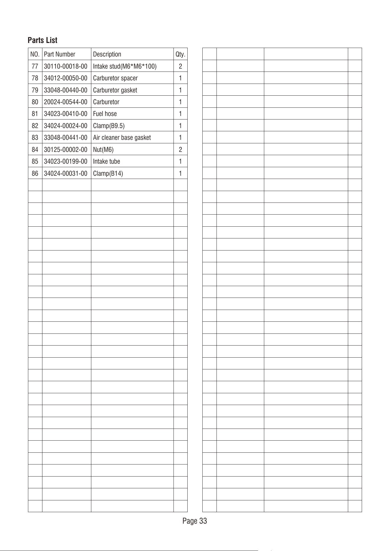
Parts List
NO.
77
78
79
80
81
82
83
84
85
86
Qty.
2
1
1
1
1
1
1
2
1
1
Part Number
30110-00018-00
34012-00050-00
33048-00440-00
20024-00544-00
34023-00410-00
34024-00024-00
33048-00441-00
30125-00002-00
34023-00199-00
34024-00031-00
Description
Intake stud(M6*M6*100)
Carburetor spacer
Carburetor gasket
Carburetor
Fuel hose
Clamp(B9.5)
Air cleaner base gasket
Nut(M6)
Intake tube
Clamp(B14)
Page 33
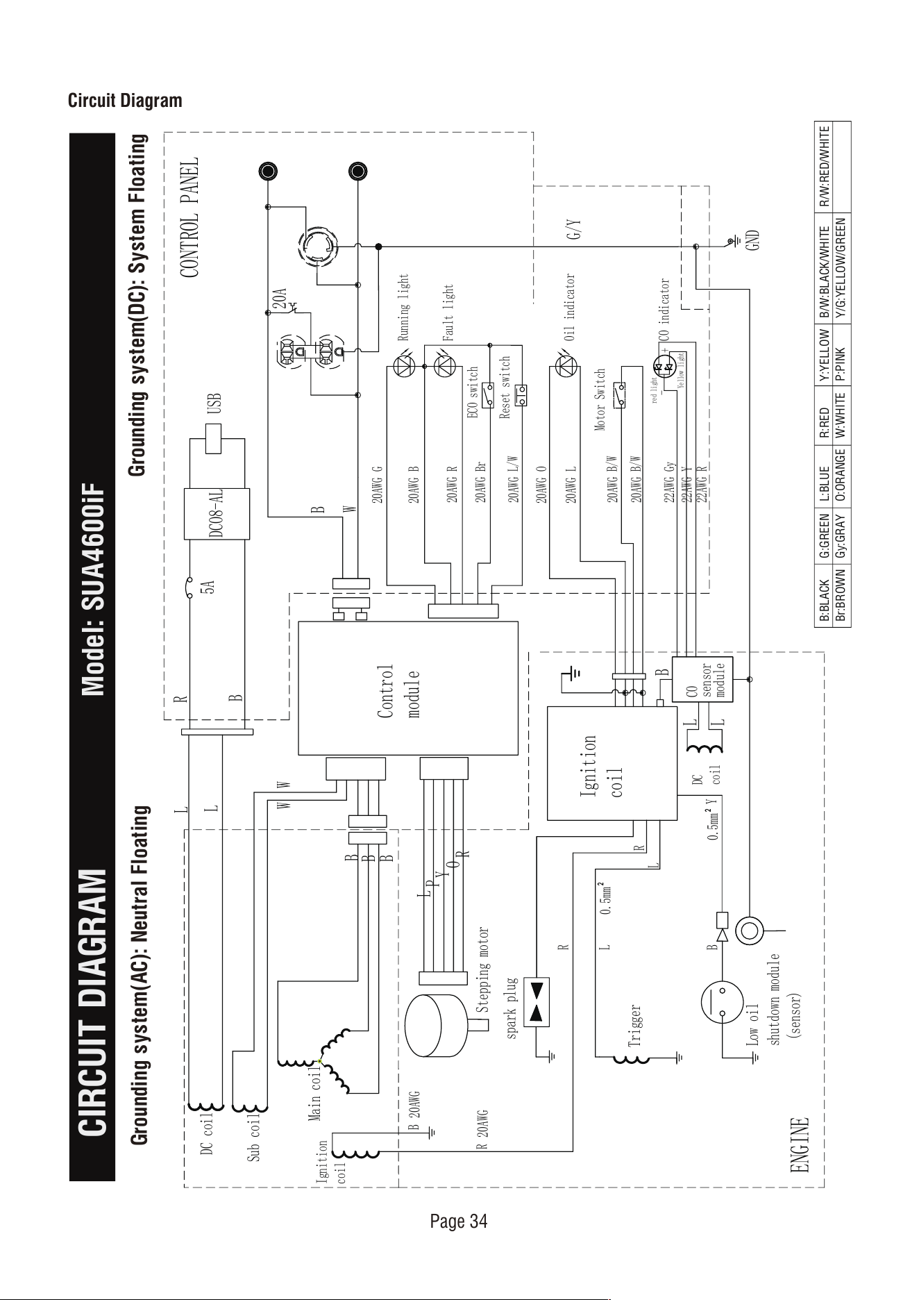
Circuit Diagram
CIRCUIT DIAGRAM
Model: SUA4600iF
Grounding system(AC): Neutral Floating
Grounding system(DC): System Floating
Page 34
B:BLACK
Br:BROWN
G:GREEN
Gy:GRAY
L:BLUE
O:ORANGE
R:RED
W:WHITE
Y:YELLOW
P:PINK
B/W:BLACK/WHITE
Y/G:YELLOW/GREEN
R/W:RED/WHITE
20AWG B
20AWG G
20AWG R
20AWG Br
20AWG O
20AWG L
20AWG
B/W
20AWG
B/W
5A
USB
20A
22AWG Gy
22AWG Y
22AWG R
Reset switch
20AWG
L/W
DCO8-AL
W
W
B
B
B
L
P
Y
R
G/Y
GND
O
B
W
0.5mm²
0.5mm²
20AWG
B
20AWG
R
Ignition
coil
Running light
Fault light
Oil indicator
Motor Switch
L
L
R
B
-
Yellow light
red light
B
+
L
L
CO indicator
Control
module
ECO switch
R
L
B
Y
R
L
Ignition
coil
Trigger
ENGINE
CONTROL PANEL
Sub coil
DC coil
Main coil
Stepping motor
Low oil
shutdown module
(sensor)
CO
sensor
module
spark plug
DC
coil
Page 35
LIMITED WARRANTY
WARRANTY
Warranty Term
WARRANTY
KEEP YOUR RECEIPT. Proof of purchase will be
required to substantiate any warranty claim.
WHAT IS COVERED: A-iPower Corp. warrants to the
original retail purchaser in the United States of
America, or Canada that this product is free of
defects in material and workmanship and agrees, at
A-iPower Corp’s direction, to either repair, provide
replacement parts for, or replace (without charge for
parts or labor) any product or component with a
material defect for a period of 3 years from the date
of purchase, except as limited below. Warranty
service and replacement parts are warranted only for
the duration of the warranty on the original product.
All replaced parts or products become a property of
A-iPower Corp.
This product is also covered by an Emissions Control
System Warranty which is separate from and in
addition to the warranty.
A-iPower Limited Warranty – 3 Years Residential and
1 Year Commercial
3 years Residential warranty applies as follow: 1st
year Parts & Labor / 2nd & 3rd year Parts ONLY
A-iPower will provide warranty for any of its products
purchased through any authorized AiPower dealer in
North America to the original purchaser and will be
warranted against defects in material or workmanship
for a period of three (3) years for Consumer use from
date of purchase, subject to exclusions noted herein.
Commercial and Rental applications are warranted for
a period of one (1) year from date of purchase.
How to Obtain Warranty Service
DO NOT RETURN THE PRODUCT TO THE PLACE
OF PURCHASE
Please call our Customer Service Dept.
855-888-3598
Please have necessary information available - Model
Number, Serial Number, Proof of Purchase
Warranty Exclusions
This warranty does not cover the following:
Regular wear and maintenance - this warranty will
not cover repair when normal use has exhausted the
lifetime of a part(s) or engine.
Installation and Maintenance - this warranty does not
cover improper or unauthorized assembly, alteration,
modification or any other damage resulting from
misuse or neglect.
Normal maintenance parts - this warranty does not
cover spark plugs, air filters, adjustments, or other
related service due to obstructions and other build
ups resulting from improper maintenance.
Additional exclusions - this warranty does not cover
wearable parts such as filers, spark plugs, o-rings,
batteries etc. It does not cover any cosmetic defects
such as scratches to paint, decals etc. It does not
cover any damage resulting from use of non-original
manufacturer’s parts, use of aftermarket parts. It
does not cover any failures due to acts of God and
A-iPower Customer Service Dept will assist with all
product related questions and will help troubleshoot
issues and will send any replacement parts as
necessary while product is within the warranty period
at no charge. If the issue cannot be resolved then
A-iPower Customer Service Dept at its discretion
determine and authorize diagnosis and repair through
one of its authorized Service Centers. A-iPower Corp
at its discretion may choose to provide replace of
part, component, or product.
Service or replacement of parts at any unauthorized
repair facility without prior authorization will not be
covered by this warranty.
“Consumer Use” - residential household use by a
retail consumer
“Commercial Use” - all other use - commercial ,
business, industrial, or rental purpose
Thank you for choosing A-iPower products. To
ensure proper registration of your product warranty,
please submit your warranty registration along with
proof of purchase within 10 days of the date of
purchase, this can be done by
a) Completing the Warranty Registration form at the
back of this manual and mailing to:
A-IPOWER CORP
10887 COMMERCE WAY UNIT A
FONTANA CA 92337 USA
b) Visit us at www.a-ipower.com and click the
product registration icon
Page 36
other force majeure events beyond the control of the
manufacturer.
Warranty limits and Implications and
Consequential Damages
A-iPower is not obligated to cover any loss of time,
use of product, freight cost, or any other incidental
or consequential claim from the use of this product.
This warranty is in Lieu of all other warranties,
express or implied.
This warranty gives you specific legal rights which
vary from state to state.
MERCHANDISE RETURN GUIDELINES
• All products must be returned in original or
equivalent packaging. Improperly packaged returns
will not be accepted.
• Must have adequate packing for transportation.
• Federal Law requires that all machines that utilize
gasoline, oil, or other flammable liquids must be
drained Completely & Thoroughly prior to shipment.
• Gas caps and oil plugs must be left off for 24
hours prior to shipping. Please note: liability for this
violation of the law resides with the sender of the
shipment.
• Return to address provided in return authorization,
using the parcel service required. Units returned
without authorization will not be honored.
• Please Note: Refunds will not be granted for items
that have been modified or damaged by abuse or
usage not in accordance with product instructions.

Fontana, CA 92337 USA
Phone: 855-888-3598
support@a-ipower.com
www.a-ipower.com
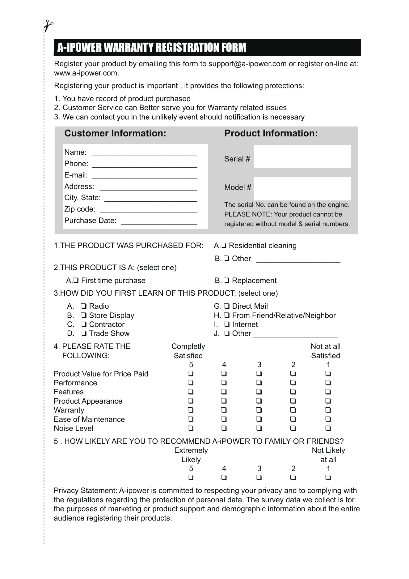
A-iPOWER WARRANTY REGISTRATION FORM
Register your product by emailing this form to support@a-ipower.com or register on-line at:
www.a-ipower.com.
Registering your product is important , it provides the following protections:
1. You have record of product purchased
2. Customer Service can Better serve you for Warranty related issues
3.
1.THE PRODUCT WAS PURCHASED FOR: A. Residential cleaning
B. Other ____________________
2.THIS PRODUCT IS A: (select one)
A. First time purchase B. Replacement
3.HOW DID YOU FIRST LEARN OF THIS PRODUCT: (select one)
A. Radio G. Direct Mail
B. Store Display H. From Friend/Relative/Neighbor
C. Contractor I. Internet
D. Trade Show J. Other ____________________
4. PLEASE RATE THE Completly Not at all
FOLLOWING:
5 4 3 2 1
Product Value for Price Paid
Performance
Features
Product Appearance
Warranty
Ease of Maintenance
Noise Level
5 . HOW LIKELY ARE YOU TO RECOMMEND A-iPOWER TO FAMILY OR FRIENDS?
Extremely Not Likely
Likely at all
5 4 3 2 1
Privacy Statement: A-ipower is committed to respecting your privacy and to complying with
the regulations regarding the protection of personal data. The survey data we collect is for
the purposes of marketing or product support and demographic information about the entire
audience registering their products.
Customer Information:
Name: _________________________
Phone: _________________________
E-mail: _________________________
Address: _______________________
City, State: ______________________
Zip code: _______________________
Purchase Date: __________________
Product Information:
Serial #
Model #
The serial No. can be found on the engine.
PLEASE NOTE: Your product cannot be
registered without model & serial numbers.

Fontana, CA 92337 USA
Phone: 855-888-3598
support@a-ipower.com
www.a-ipower.com