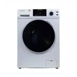
Model: 4800 V
VENTING
1
2
5
6
8
9
10
11
12
14
15
16
17
18
19
20
21
Introduction
Warranty Information
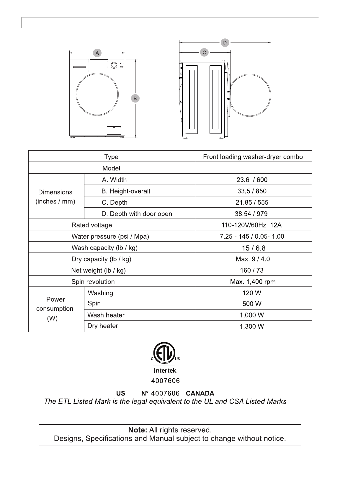
Technical Specifications
Safety
Diagram of the Combo Washer + Dryer
Unpacking and Leveling
Handling and Placement
Electrical and Plumbing
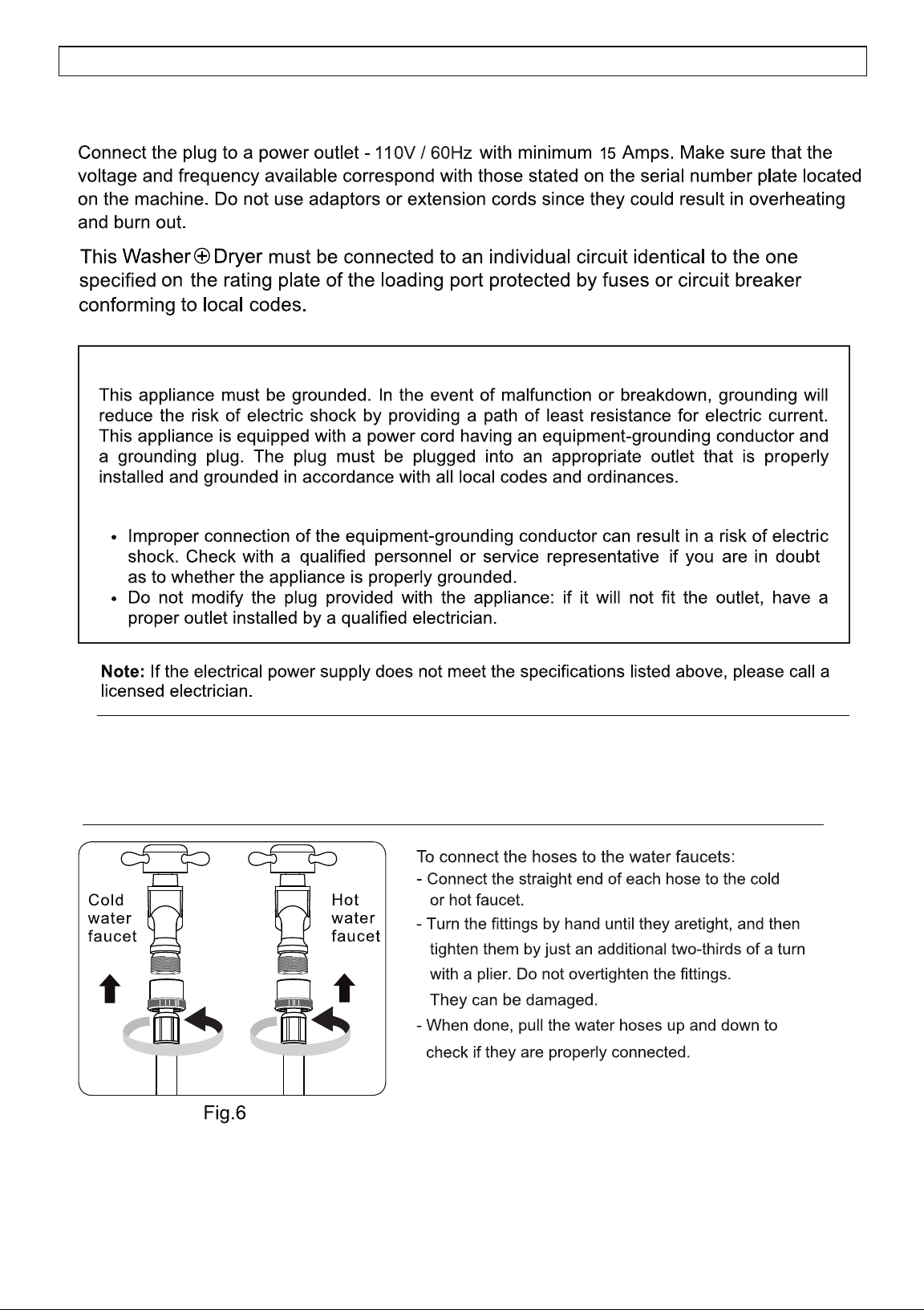
Connecting Hoses
Operating Instructions
Program Selection Chart
Control Panel
Display Panel
Special Features and Programs
Maintenance
Troubleshooting
Error Codes
TABLE OF CONTENTS
attachment
Washer + Dryer
Washer + Dryer!
1
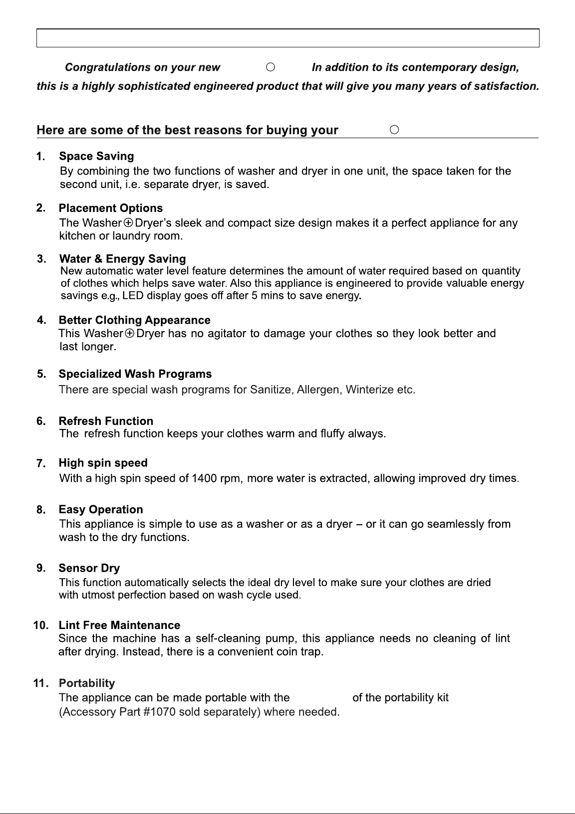
INTRODUCTION
2
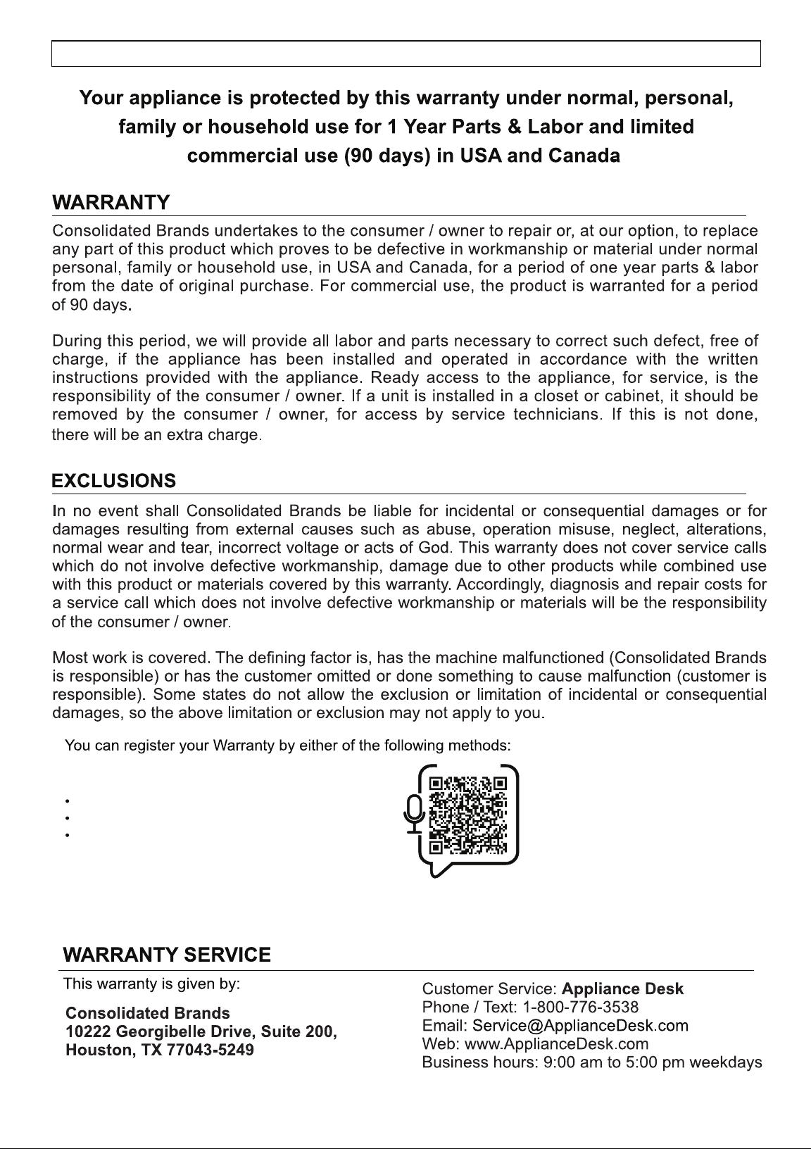
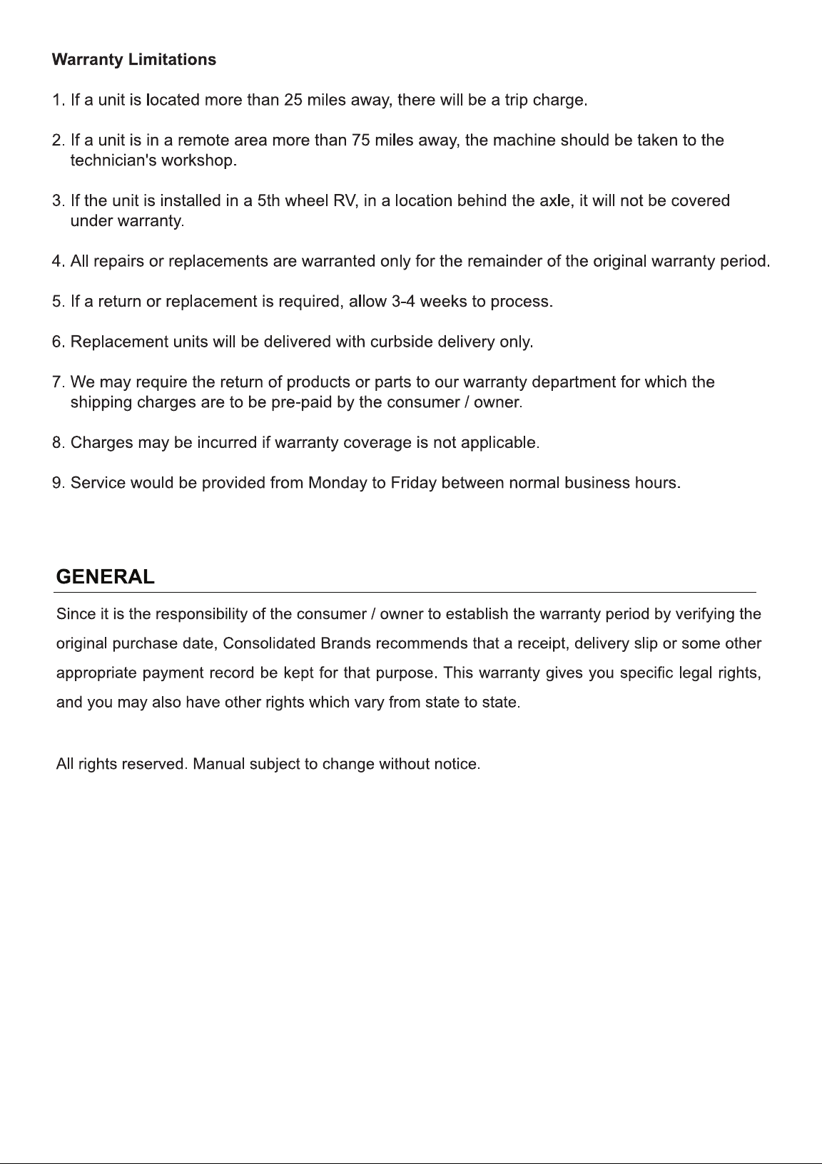
WARRANTY INFORMATION
1. Scan QR Code
Open Smart Phone
Open Camera
Click the Link
2. Register online at ApplianceDesk.com/Warranty
Note: QR Code is also used to obtain Product Information, Manuals and Updates
Chat-AI
Placement
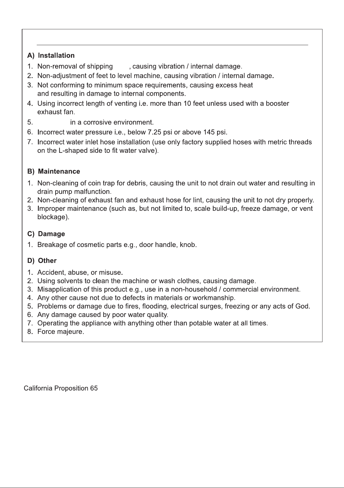
THE FOLLOWING IS NOT COVERED UNDER WARRANTY
WARNING: This product contains chemicals known to the State of California to cause cancer and birth defects or
other reproductive harm.
rods
3
4
4800 V
TECHNICAL SPECIFICATIONS
5
manufactured in compliance with
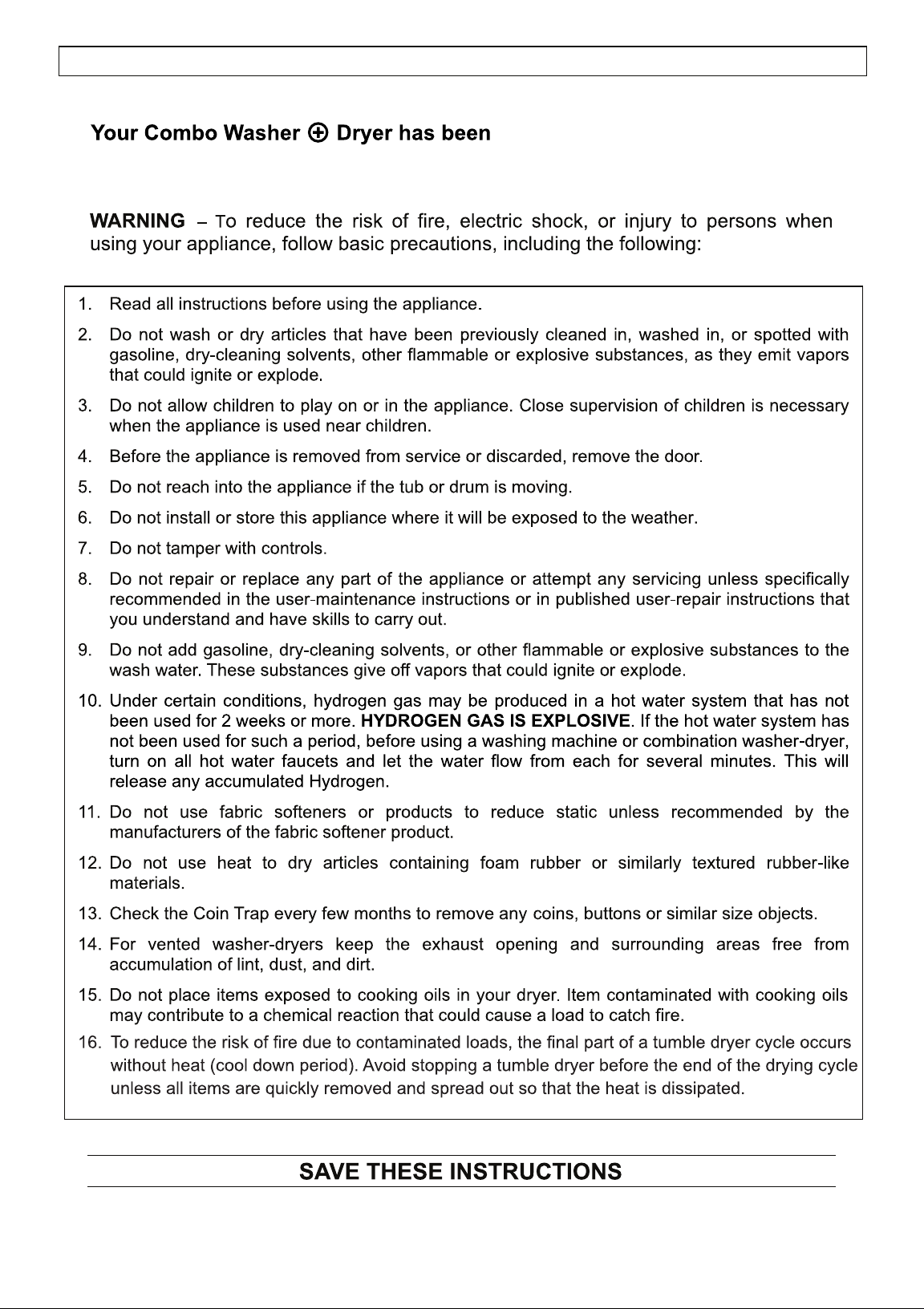
safety regulations to protect you and your family.
6
IMPORTANT SAFETY INSTRUCTIONS
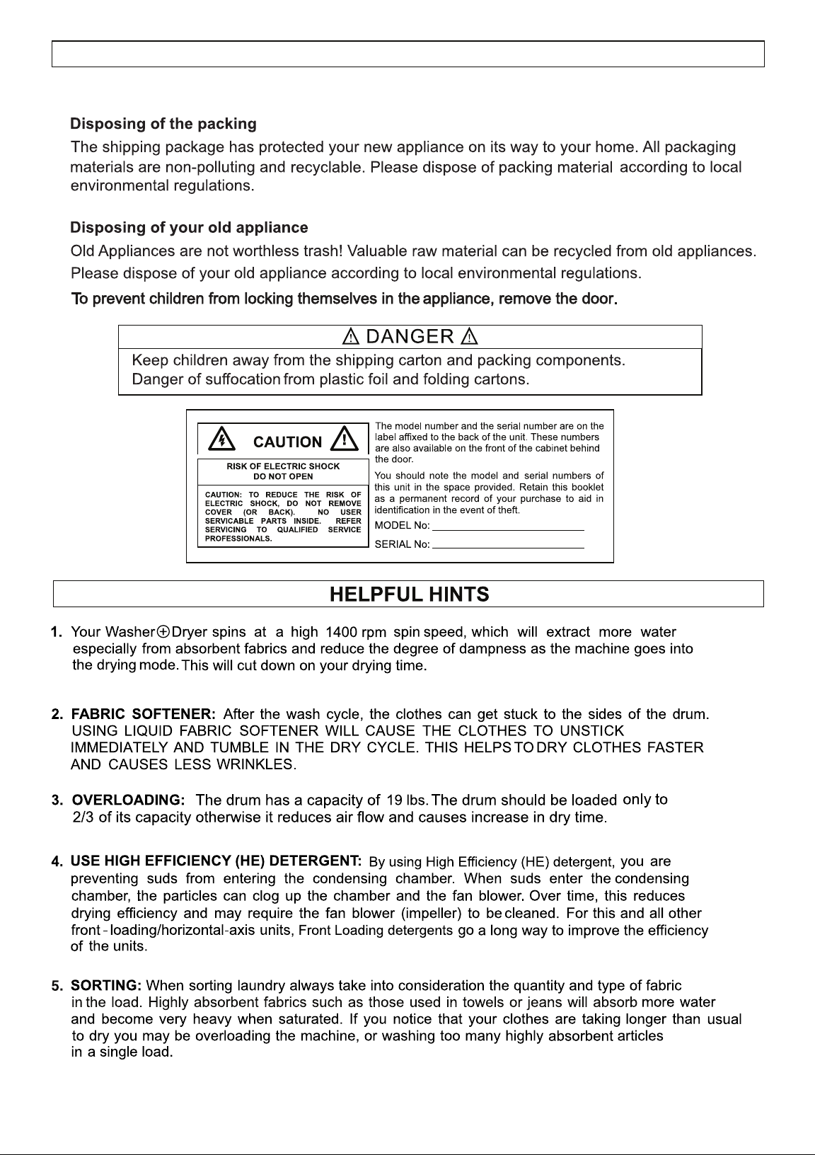
SAFE DISPOSAL
7
Ensure the appliance is placed on a solid and
level surface so that during the spinning, the machine will not move or shake.
SAFETY
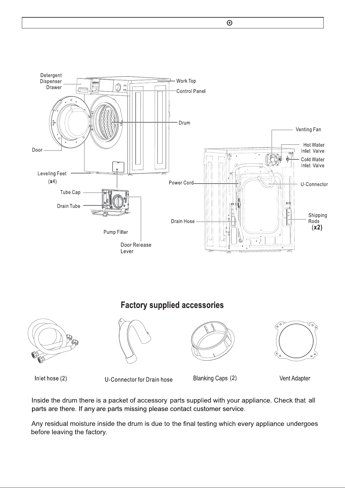
DIAGRAM OF THE COMBO WASHER DRYER
8
Washer + Dryer
Washer + Dryer
rod
rods.
rods
rod
rods
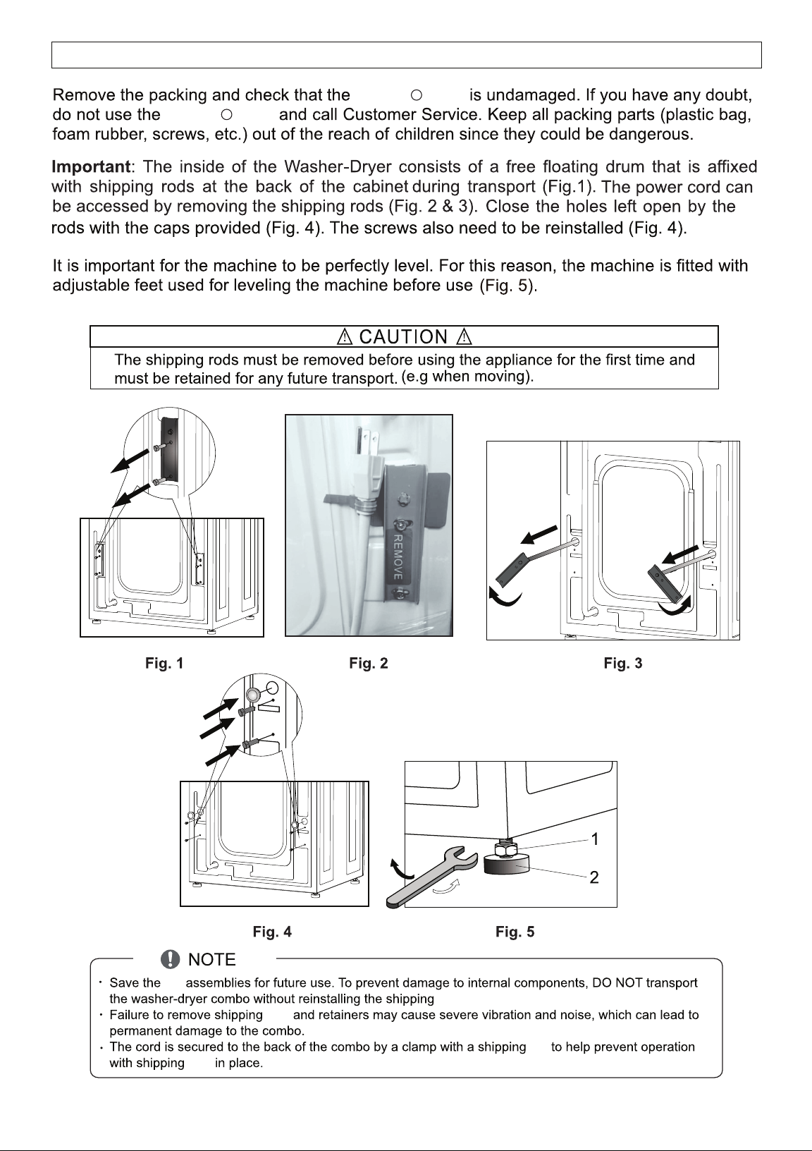
UNPACKING and LEVELING
9
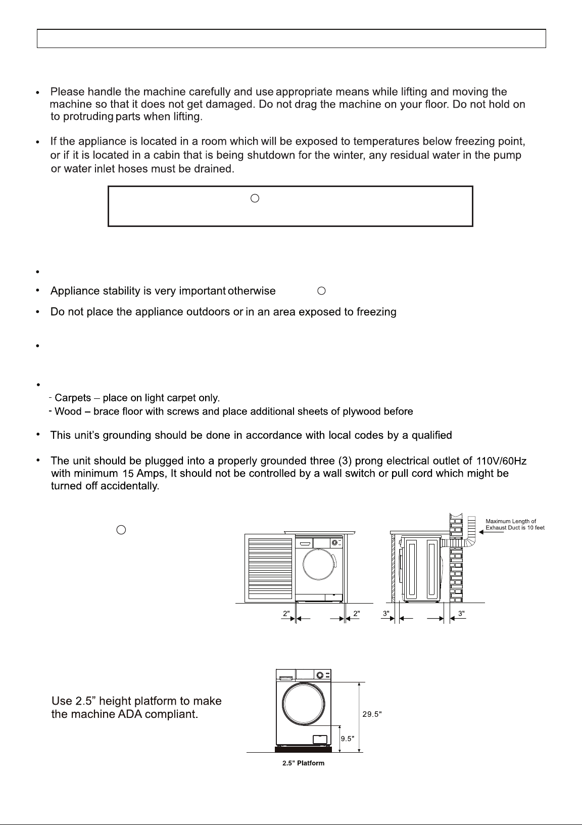
HANDLING and PLACEMENT
Placement
Place the appliance in a protected, dry and well-ventillated area, with a power and water supply of
sufficient capacity and a sufficient outlet in close proximity.
Placement on carpet or wood increases vibrations.
placement of unit.
technician.
Handling
Place the appliance on a hard and flat surface.
The Washer + Dryer is designed
to be Freestanding or Built-in.
Ensure there is minimum
clearance space around the
appliance: 2 inches on either
side and 3 inches at the front
and at the back.
Washer + Dryer is Venting only
Ensure the appliance is placed in an area where it can be vented.
Fig. 7
10
washer + dryer could “wander” during the spin cycles.
conditions.
Frozen hoses can tear / burst.
Fig. 6
GROUNDING
WARNINGS
11
ELECTRICAL and PLUMBING
Electrical Connection
Connecting to the Water Faucet
Plumbing
Connecting to the Appliance
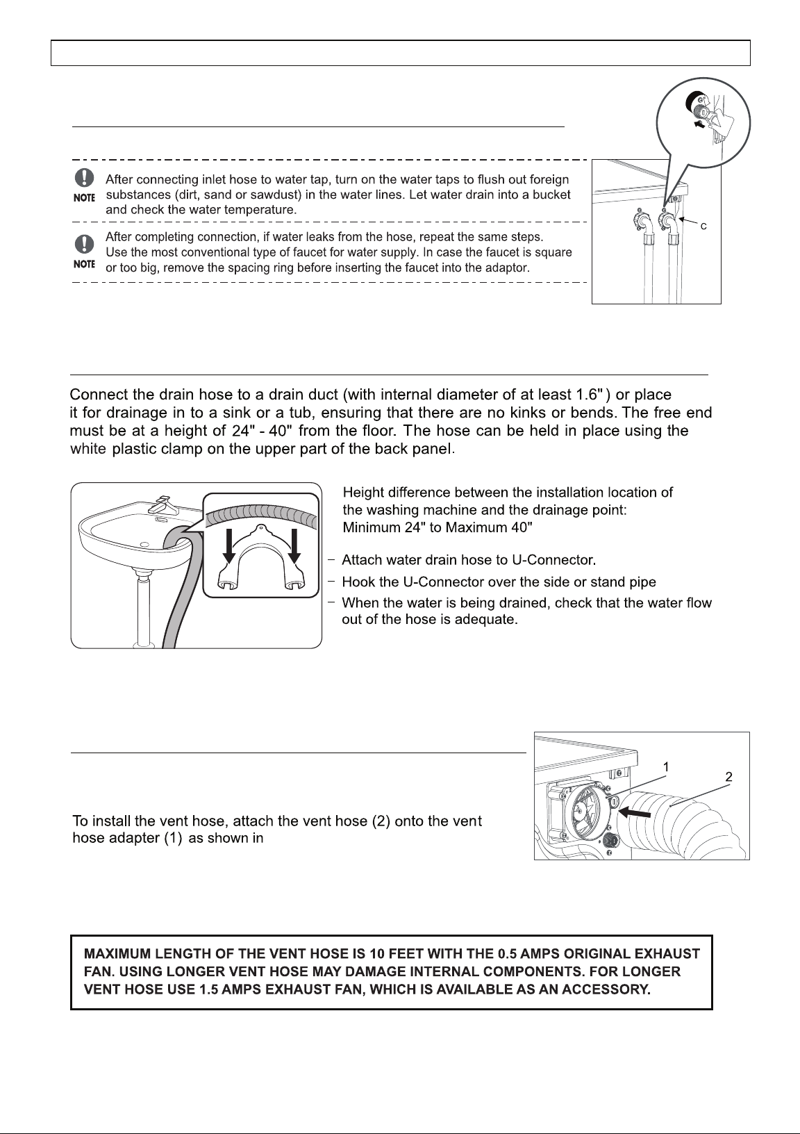
Connecting to the Drain Hose
Fig. 8
Fig. 9
(Fig. 9)
12
CONNECTING HOSES
The Super Combo vents the moist hot air out of the unit and
requires a vent hose (standard 4” diameter) to be installed.
IMPORTANT: Dryer vent connections and services must be performed by a qualified technician.
Fig. 10
Fig. 10.
Connecting the Dryer Vent Duct
Ensure that there are no kinks in the hose and that they are not crushed. (Fig. 8).
Tighten all joints to aviod leaks. The male end of the duct must point away from the machine.
Separate all turns by at least 3 feet(1 meter) of straight duct, including distance between last turn and
dampened wall cap. If two turns must be closer than 3 feet (1 meter) deduct 10 feet (3 meters) from the
maximum length.
WARNINGS: The machine must be exhausted outdoors.
The Exhaust Fan and Exhaust Duct should be cleaned once a year.
13
(Fig.11).
For small items such as socks and children’s clothes, please use a washing net bag.
Fig.11
14
OPERATING INSTRUCTIONS
15
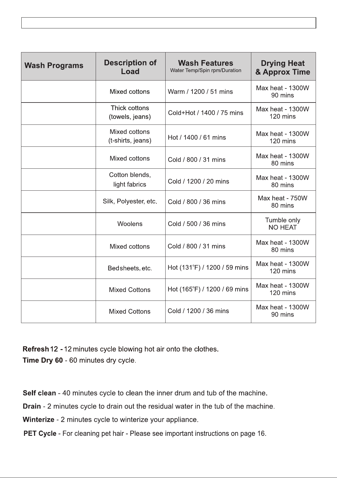
PROGRAM SELECTION CHART
WASH & DRY, WASH ONLY, DRY ONLY
DRY CYCLES
OTHER CYCLES
1 - NORMAL
2 - Prewash + Heavy
3 - Heavy
4 - ECO
5 - Quick 20’
6 - Delicate
7 - Wool
8 - Quiet 60 dB
o
9 - Allergen 131
o
10 - Sanitize 165
11 - PET Cycle
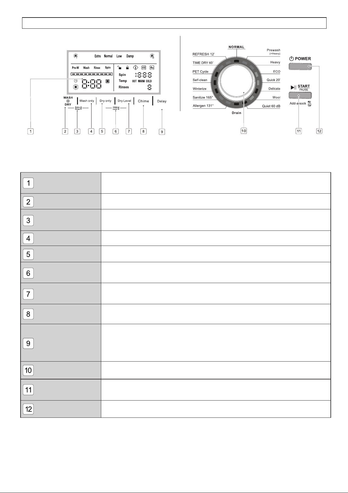
Colored LED Display
Wash + Dry
Extra Rinse
Wash only
Dry only
Child Lock
Dry Level
Chime
Delay
Program Dial Knob
Start / Pause button
Power button
Displays the information of selected program, such as the water temperature,
spin speed, remaining time, rinse times, wash cycles and error messages.
Press to select wash & dry cycles together.
To add an extra rinse to the selected cycle, press Wash + Dry and Wash only
for 3 seconds before starting.
Press to select only the wash cycle.
Press to select only the dry cycle.
To prevent children from playing with your machine, press Dry only and Dry
Level at the same time for 3 seconds when machine is running.
Press to select the dry level for a Sensor Dry cycle.
The default is Normal. You can select Extra, Low or Damp Dry.
Press for 3 seconds to turn the chime on or chime off when your
machine is running.
To delay the start of the wash cycle, press Delay to select the delay time
from 1 to 24 hours, increasing in one-hour increments. To change the delay
time, turn the dial to another program, then back to the desired program and
reset the delay time.
Press this button to turn the machine on. Press and hold down this button
to turn it off.
Turn the dial to point to one of the 16 programs depending on the load.
Press this button to start, or interrupt the selected wash program, or to view the
display during a cycle.
CONTROL PANEL
16
Venting dry mode
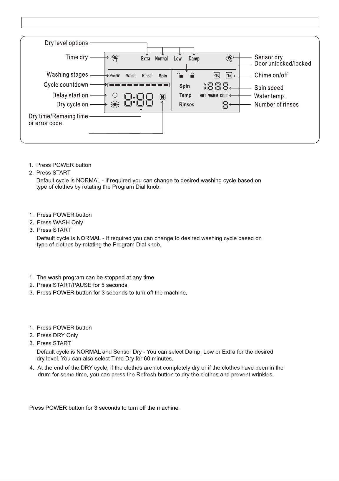
DISPLAY PANEL
How to run Wash + Dry Cycle
How to run Wash Only Cycle
How to run Dry Only Cycle
How to stop the Dry cycle
How to stop the Wash cycle
17
remaining water.
Door Lock Function
How to turn on the display in energy saving mode?
Add-a-sock Feature
Winterizing
Pet Cycle
18
SPECIAL FEATURES AND PROGRAMS
Clean the exhaust fan and exhaust duct at least once a year to prevent lint build-up.
+
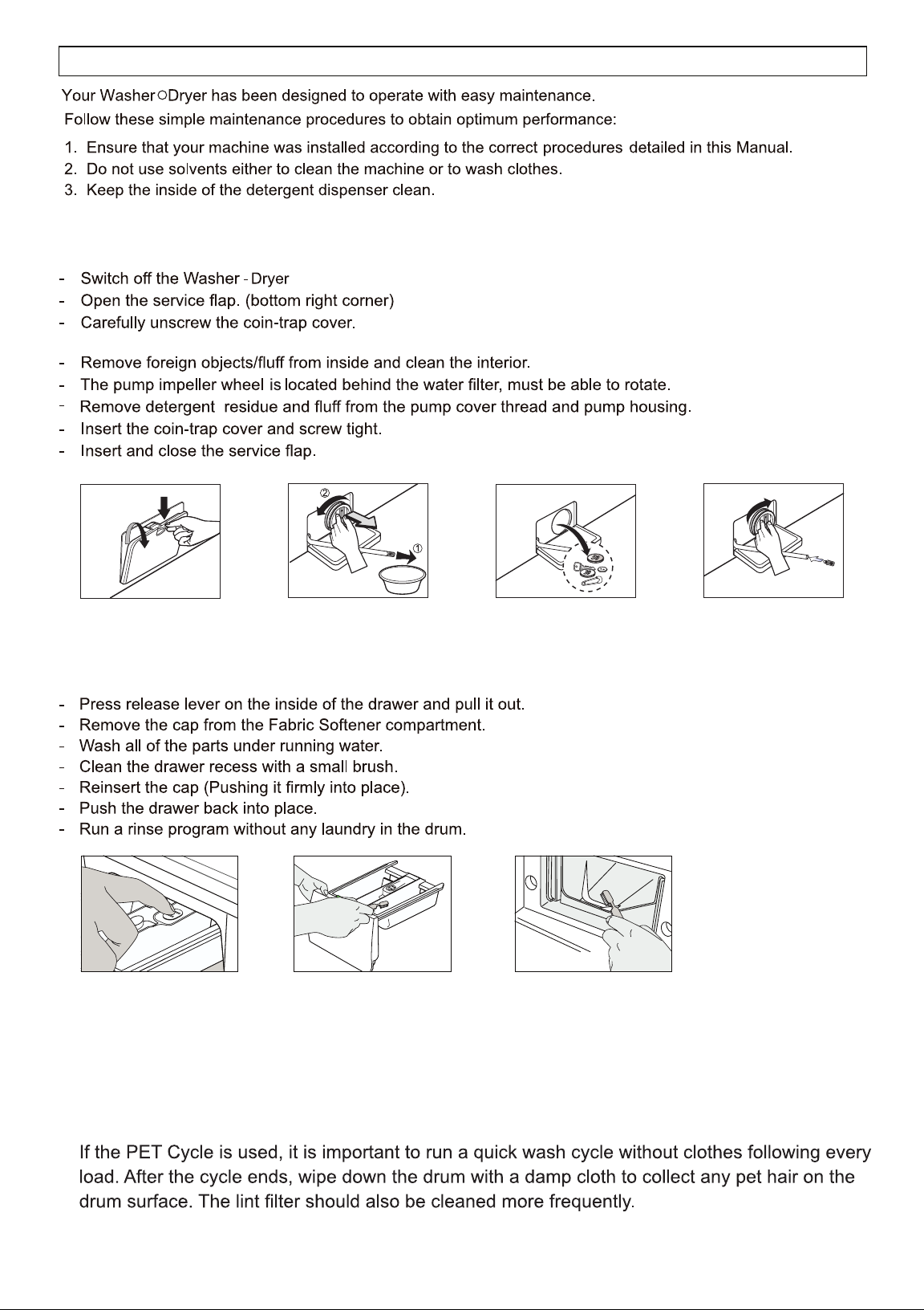
Fig. 12 Fig. 13 Fig. 14 Fig. 15
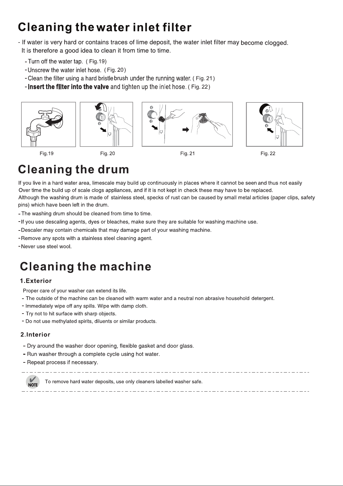
(Fig.17, Fig.18)
MAINTENANCE
Cleaning the Coin Trap
Warning: Some residual water will flow out (approx. 1 cup). Place a pan below the opening.
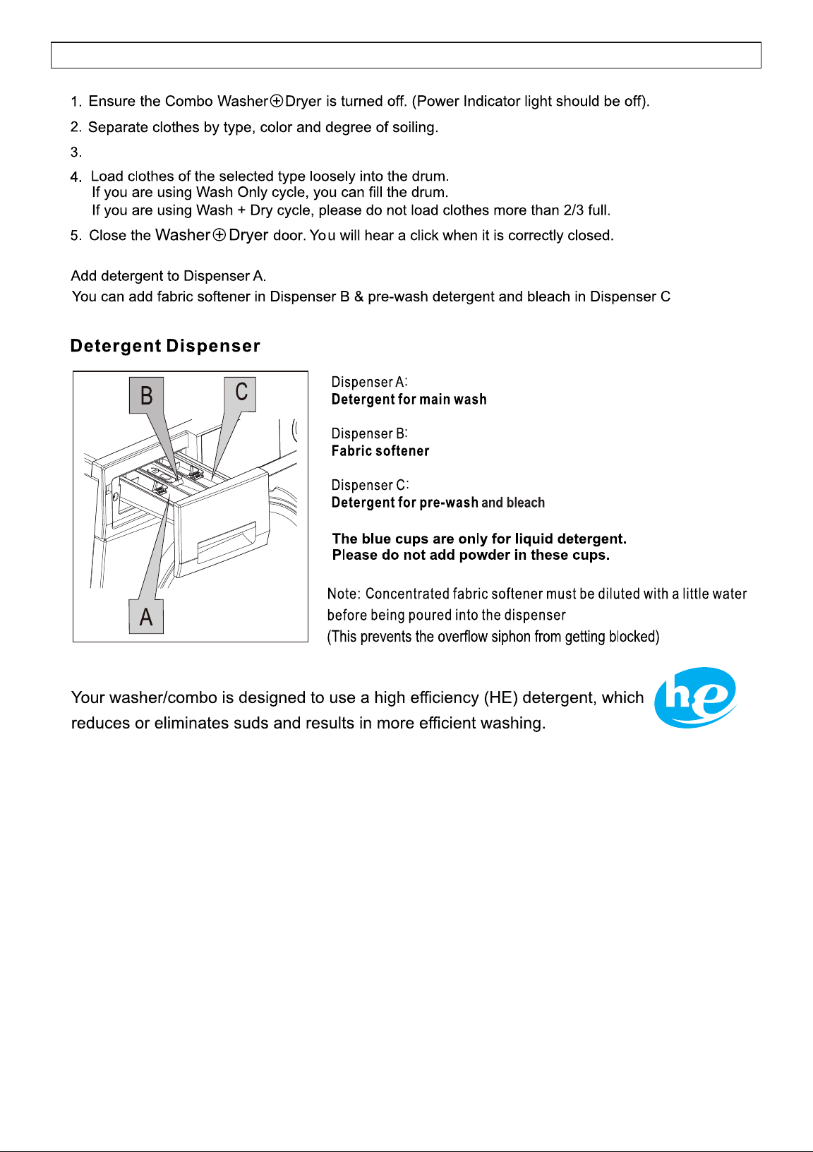
Cleaning the Detergent Drawers
Cleaning the Exhaust Fan and Duct
Pet Cycle - Maintenance
19
(Fig.12)
(Fig.13)
(Fig.14)
(Fig.15)
Fig. 16 Fig. 17 Fig. 18
(Fig.16)
20
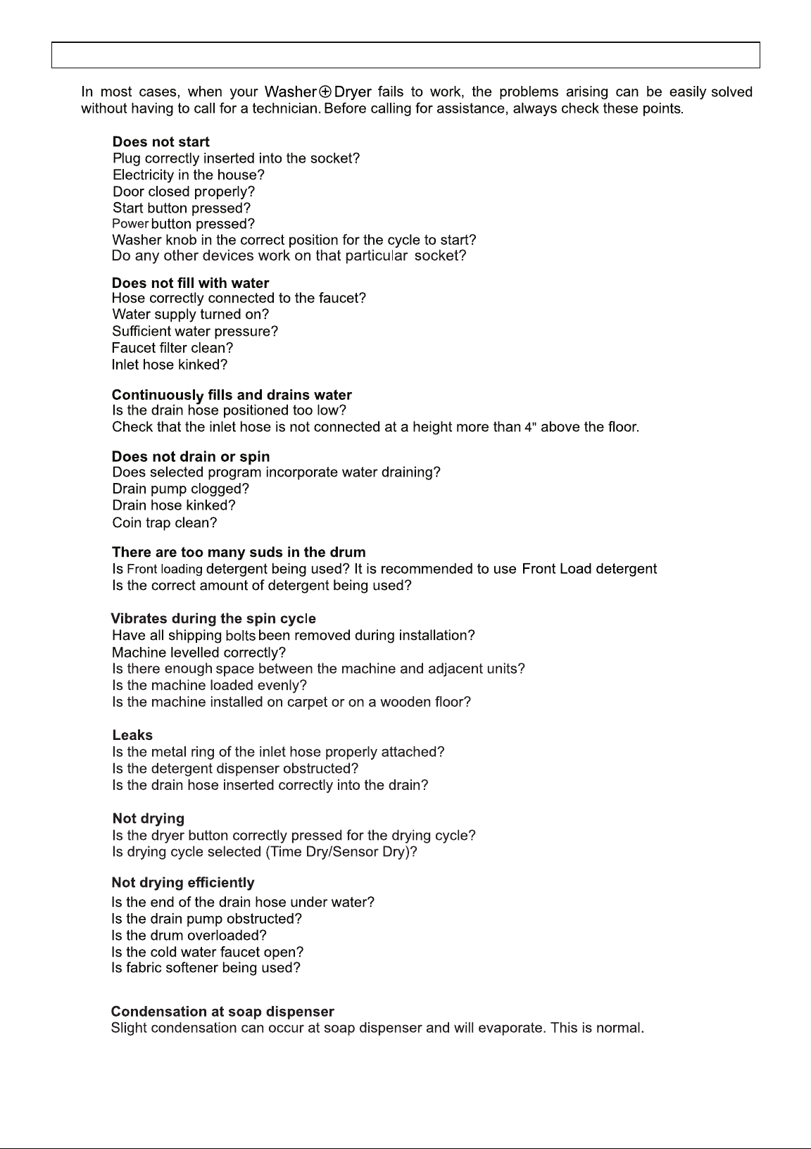
TROUBLESHOOTING
20
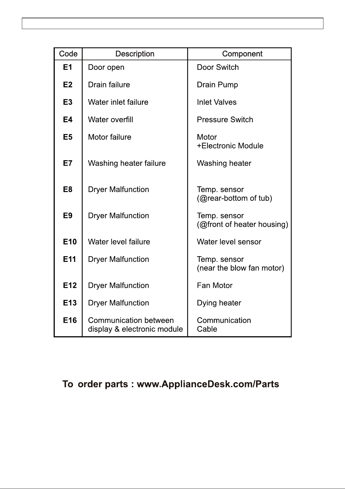
ERROR CODES
21